PSIPSI Power supply Interface for Motornet DC Guida rapida all’installazione Quick installation...
11
PSI Power supply Interface for Motornet DC Guida rapida all’installazione Quick installation guide rev. 0.1 Settembre 2010 September 2010
Transcript of PSIPSI Power supply Interface for Motornet DC Guida rapida all’installazione Quick installation...

PSI Power supply Interface for Motornet DC
Guida rapida all’installazione Quick installation guide
rev. 0.1 Settembre 2010 September 2010

Parker Hannifin SpA PSI Manuale utente – PSI User’s manual
Pagina 2 di 11
ISTRUZIONI PER LA SICUREZZA
Aspetti generali della sicurezza Tutte le attività di trasporto, montaggio, installazione, messa in servizio e manutenzione possono essere eseguite esclusivamente da personale tecnico qualificato ed addestrato che abbia familiarità con il trasporto, il montaggio, l’installazione, la messa in servizio ed il funzionamento del prodotto. E’ inoltre dovere dell’utilizzatore far sì che l’installazione avvenga secondo le vigenti norme di sicurezza sul lavoro. Prima di procedere all’istallazione ed alla messa in servizio, leggere con attenzione il presente manuale e rispettare scrupolosamente tutti i dati tecnici, di sicurezza e di collegamento in esso contenuti, comprese anche le etichette identificative presenti sull’ azionamento stesso (dati di targa). In caso di dubbi contattare il nostro Servizio Assistenza. Gli azionamenti sono da intendersi come componenti destinati ad essere utilizzati all’ interno di macchine o sistemi. Pertanto possono essere utilizzati solamente all’ interno di macchine o sistemi conformi alla direttiva macchine (direttiva bassa tensione 73/23/CEE modificata da 93/68/CEE) e alla direttiva sulla compatibilità elettromagnetica 89/336/CEE. I dispositivi elettronici non sono, in generale, “fail-safe”. Pertanto il costruttore della macchina è tenuto a realizzare un’ analisi dei rischi per l’intera macchina in modo da assicurare che gli organi di movimento (motori) non causino danni a persone o cose anche nell’ eventualità di guasti ai dispositivi elettronici.
Sicurezza per trasporto ed immagazzinamento Rispettare le specifiche ambientali relative all’ immagazzinamento e trasporto presenti in questo manuale (temperatura, umidità, stress meccanici e atmosfera corrosiva). Gli azionamenti contengono parti sensibili alle scariche elettrostatiche che possono essere danneggiate da una manipolazione non appropriata. Pertanto nella manipolazione dell’ azionamento occorre prendere le necessarie precauzioni di sicurezza contro le scariche elettrostatiche (scaricare l’elettricità statica del corpo prima di toccare l’ azionamento, collocare sempre l’ azionamento su supporti conduttivi ed evitarne il contatto con materiali altamente isolanti come fibre sintetiche, materiali plastici etc…) Rischio di gravi lesioni !: Una manipolazione scorretta dell’ azionamento può causare gravi lesioni alle persone. Utilizzare strumenti appropriati per il trasporto, il sollevamento e il montaggio. Utilizzare appropriati abiti antinfortunistici (scarpe, occhiali, guanti, etc...).
Sicurezza per istallazione e messa in servizio Le alte tensioni presenti all’interno del drive e sui terminali di collegamento comportano un elevato rischio di scossa elettrica. Assicurarsi che azionamento e motore siano correttamente messi a terra secondo le norme vigenti. Inoltre l’azionamento, prima di essere alimentato, deve essere chiuso in un armadio (quadro) di protezione per evitare il contatto diretto con le parti in tensione. L’istallazione e la messa in servizio del drive possono essere eseguita solo da personale qualificato. L’istallazione inoltre deve essere eseguita con gli opportuni utensili e con le comuni precauzioni. Le operazioni di istallazione e di cablaggio devono sempre essere svolte in completa assenza di tensione. Il drive può essere allacciato solo a reti elettriche industriali TT, TN aventi una tensione massima di 230V+10% e conformi alla specifica riportata nel presente manuale. Controllare sia i dati tecnici dell’ azionamento, sia le istruzioni di collegamento alla rete. Non utilizzare su reti isolate (IT) o con messa a terra non simmetrica, se non interponendo un trasformatore Dyn con centro stella secondario a terra. I componenti del quadro elettrico in cui è installato il drive (cavi, contattori, induttanze, fusibili, etc.), ed i motori collegati, devono essere conformi alla specifica riportata nel presente manuale e alle norme vigenti. Mantenere all’ interno dei quadri una temperatura inferiore a 45°C (113°F) tramite un opportuno condizionamento. I cavi utilizzati per il collegamento del drive devono avere sezione compatibile con la specifica riportata nel presente manuale e devono essere serrati con le specificate coppie di serraggio. Utilizzare appropriati utensili per fissare i capocorda. Per istallazioni negli USA riferirsi alla norma NEC tabella 310-16. Assicurarsi del corretto abbinamento drive-motore: i valori di targa di corrente e tensione devono essere compatibili. L’ utilizzatore è responsabile per le protezioni di sovracorrente e corto circuito. Leggere attentamente le specifiche di questo manuale.
Sicurezza per il funzionamento Alta tensione ! Rischio di scarica elettrica ! Pericolo di vita ! Tutte le parti in tensione del drive (connessioni) devono essere protette dal contatto accidentale. Il drive, prima di essere alimentato, deve essere chiuso in un armadio di protezione. L’intervento sui terminali di potenza deve essere eseguito con il drive non alimentato. Tensioni pericolose possono rimanere presenti sui terminali anche dopo aver tolto l’alimentazione al drive e con motore fermo. Dopo aver rimosso la tensione di alimentazione di potenza, attendere almeno 6 minuti prima di intervenire sui terminali del drive. Il drive e il motore devono essere permanentemente connessi a terra, anche se alimentati per brevi periodi o durante la fase di messa a punto dell’apparecchiatura. Elevata corrente di fuga ! Rischio di scarica elettrica ! Pericolo di vita ! La corrente di fuga a terra durante il normale funzionamento può essere maggiore di 3,5 mA AC oppure 10 mA DC La connessione alla terra di protezione deve essere fissa (permanente) e deve essere eseguita tramite un conduttore avente sezione ≥10mm2 per tutta la sua lunghezza. Prima di alimentare l’azionamento, verificare che tutti i dispositivi, motore compreso, siano permanentemente collegati a terra, anche se per brevi prove o misure, come indicato nel presente manuale. In caso contrario, l’involucro dell’ azionamento potrebbe trovarsi ad una tensione elevata con conseguente rischio di scarica elettrica. Per la messa a terra riferirsi sempre alle norme vigenti. Per installazioni nella Comunità Europea riferirsi alla norma EN61800-5-1, paragrafo 4.2.5.4.2. Per istallazioni negli USA riferirsi alle norme NEC (National Electric Code) e NEMA (National Electric Manufacturers Association). Superfici estremamente calde ! Pericolo di danno a persone e cose. Alcune superfici esterne dell’ azionamento raggiungono temperature molto elevate. Il contatto con queste superfici può causare danni a persone e cose. Dopo aver spento l’azionamento, attendere almeno 15 minuti che le superfici si raffreddino prima di poterle toccare.
Movimenti pericolosi ! Pericolo di vita ! Per prevenire danni a persone e cose, dovuti ad errati movimenti del motore, occorre avere il massimo grado di attenzione, operando sulla macchina con un sistema in sicurezza qualificato e collaudato.
Compatibilità con interruttori differenziali E’ fortemente sconsigliato l’ utilizzo di interruttori differenziali. Se l’utilizzo di tali dispositivi fosse obbligatorio, utilizzare esclusivamente differenziali di tipo B (per correnti di corto a terra sia AC che DC) tarati ad un livello di 300mA (massimo livello ammissibile per la protezione dal fuoco), o anche maggiore se necessario per l’applicazione. Un livello di taratura a 30mA (massimo livello ammissibile per la protezione delle persone contro il contatto diretto) è possibile solamente se si utilizzano differenziali ritardati e filtri EMC a bassa corrente di fuga, ma comunque non è un livello garantito per questo tipo di apparecchiature industriali.
Quadro normativo: Sicurezza direttiva 73/23/CEE mod. da 93/68/CEE Direttiva bassa tensione EN 60204-1 Safety of machinery – Electrical equipment of machines – Part 1: General requirements EN 61800-2 Adjustable speed electrical power drive systems – Part 2: General requirements – Rating specifications
for low voltage adjustable frequency a.c. power drive systems EN 61800-5-1 Adjustable speed electrical power drive systems – safety requirements, thermal and energy
Quadro normativo: Compatibilità Elettromagnetica (Immunità/Emissione) direttiva 89/336/CEE Direttiva EMC EN 61800-3 Azionamenti elettrici a velocità variabile. Parte 3: Requisiti di compatibilità elettromagnetica e metodi di prova
specifici Gli azionamenti sono da intendersi come componenti per uso nel secondo ambiente (ambiente industriale) in categoria C3, quando accompagnati da specifici filtri anti-disturbo e installati secondo le raccomandazioni fornite nel presente manuale. Se utilizzati nel primo ambiente (ambiente residenziale), possono produrre radio-interferenze pericolose per le altre apparecchiature : l’utilizzatore è tenuto ad adottare misure di filtraggio addizionali.
Materiali impiegati e smaltimento I condensatori contengono soluzione elettrolitica e i circuiti stampati contengono piombo. Entrambe le sostanze sono classificate come pericolose e devono essere rimosse e trattate secondo le norme vigenti. Secondo la normativa EU 2002/96/CE, la società Parker Hannifin Divisione S.B.C., insieme ai distributori locali, si impegna a ritirare i propri prodotti per smaltirli nel pieno rispetto dell’ambiente.

Parker Hannifin SpA PSI Manuale utente – PSI User’s manual
Pagina 3 di 11
SAFETY INSTRUCTIONS General information
Only persons who are qualified and trained for the use and operation of the equipment may work on this equipment or within its proximity. The persons are qualified if they have sufficient knowledge of the assembly, transportation, installation and operation of the equipment as well as an understanding of all warnings and precautionary measures noted in these instructions. The user must also observe local safety regulations. Before installing and commissioning the drive, read carefully this documentation and strictly observe all technical, safety and wiring information, including identifying labels placed on the drive (ratings). In case of doubt contact the Parker Hannifin service centre. Drives are to be intended as components for use in machine or systems. Therefore they can be used only in machine or systems that are in compliance with the low voltage directive 73/23/CEE (modified by 93/68/CEE) and with the electro-magnetic compatibility directive 89/336/CEE. Electronic equipments are generally not “fail-safe” components. Therefore the machine manufacturers should carry out a risk analysis for the whole machine in order to ensure that moving parts (motors) cannot bring personal injury in case of failures of electronic devices.
Safety instructions for transportation and storage The ambient conditions given in the product documentation must be observed for transportation and storage (temperature, humidity, mechanical stress and aggressive atmosphere). Drives contain components sensitive to electrostatic charges which can be damaged by inappropriate handling. Therefore during installation / removal of drives, provide the necessary safety precautions against electrostatic discharges (discharge electrostatic charges of the human body before touching the drive, always place the drive above conductive plates and avoid touching it with insulating material like synthetic fibres, polymeric materials etc…) Risk of injury by incorrect handling ! Incorrect handing of the equipment may cause severe personal injury. Use appropriate tools for transportation, lifting, handling and mounting. Wear appropriate clothing for accident-prevention (safety shoes, safety glasses, safety gloves, etc...).
Safety instructions for commissioning The high voltages inside the drive imply risk of electric shock. Make sure that drive and motor are properly grounded accordingly to national regulations. Furthermore the drive, before switching it on, must be closed in a protective cabinet in order to avoid direct contact with accessible live parts. Only qualified and trained personnel is allowed to perform installation and commissioning, using appropriate tools and following the safety precautions given in this instruction. Make sure that supply voltage has been switched off before installing and wiring. Drives are only allowed to be operated on TT, TN grounded industrial mains having maximum 480V+10% line to line rms voltage, as specified in the user manual. Do not directly install the drive on ungrounded (IT) or asymmetrically grounded mains. In case of ungrounded mains, coupling with Dyn transformer with grounded secondary circuit is necessary. Refer to drive technical data and wiring instruction. All the components used in the cabinet in which the drive is installed, (cables, contactors, inductors and transformers, fuses, etc...), and the connected motor, must be in compliance with the specification given in the product documentation, in addition to national regulations. Make sure that the maximum temperature inside the cabinet does not exceed 45°C (113°F). If necessary, use an appropriate air conditioning. The size and temperature rating of wires and cables used for connecting the drive must be in compliance with the specification given in the instruction manual (see NEC 310-16 for USA). Use also the specified tightening torque. Make sure about the correct drive-motor matching: voltage and current ratings must be compatible. The user is responsible for over-current and short circuit protection of the drive. Read carefully the specification given in the user manual.
Safety instructions for operation High voltage ! Risk of electric shock ! Danger of life ! All live parts must be protected against direct contact. The drive must be closed inside a cabinet before switching it on. Working on power live parts (terminals) must be conducted with the drive switched-off. Dangerous voltages may be present at power terminals even after the supply has been switched off and the motor stopped. Make sure the equipment cannot switched on unintentionally. Wait at least 6 minutes before working on live parts after the unit has been switched-off. The drive and the motor must be permanently connected to earth accordingly to the connection diagram, even for brief measurements or tests. High leakage current ! Risk of electric shock ! Danger of life ! Earth leakage current during operation may exceed 3,5 mA AC or 10mA DC. Earth connection must be permanent : use copper wire having a minimum size of 10mm2 throughout all the length. Before switching the equipment on, make sure that all devices, including the motor, are permanently connected to earth, even for brief test or measurements, as shown in the wiring diagrams. Otherwise high voltages may appear on equipment conductive surfaces with danger of electrical shock. Always refer to current local regulations for grounding. For installation within European Community refer to EN61800-5-1 product standard, section 4.2.5.4.2. For installation in the USA refer to NEC (National Electric Code) and NEMA (National Electric Manufacturers Association). The product installation should always comply with the above said standards. Hot surfaces ! Danger of injury ! Danger of burns ! Some external surfaces of the equipment and same internal part may reach very high temperatures. Danger of burn and injury if touching these parts. After switching the equipment , wait at least 15 minutes to allow it to cool before touching it.
Dangerous movements ! Danger of life ! In order to prevent personal injury due to unintended dangerous motor movements, pay the maximum attention and work on the machine with a qualified and tested safety system.
Compatibility with RCD devices The use of RCD (Residual Current Devices) is strongly not recommended. If the use of RCD is mandatory, use type B only (for DC and AC prospective earth current). Set the trip level at 300mA (fire protection level) or more. Setting the trip level at 30mA (protection level against direct contact) is possible only using time-delayed RCD and low leakage current EMC filters, but in any case the drives are not guaranteed to operate with 30mA trip level.
Applicable standards: Safety 73/23/CEE directive mod. by 93/68/CEE Low voltage directive EN 60204-1 Safety of machinery – Electrical equipment of machines – Part 1: General requirements EN 61800-2 Adjustable speed electrical power drive systems – Part 2: General requirements – Rating specifications for
voltage adjustable frequency a.c. power drive systems EN 61800-5-1 Adjustable speed electrical power drive systems – safety requirements, thermal and energy
Applicable standards: Electromagnetic Compatibility (Immunity/Emission) 89/336/CEE directive EMC directive EN 61800-3 Adjustable speed electrical power drive systems. Part 3 : EMC product standard including specific test method
The drives are to be intended as components to be used in a second environment (industrial environment) and category C3, together with specific EMC filters and installed accordingly to the recommendation given in the user manual. When used in the first environment (residential / commercial environment), drives may produce radio-frequency interference dangerous for other equipments : additional filtering measures must be implemented by the user.
Materials and disposal Electrolytic capacitor contain electrolyte and printed circuit boards contain lead, both of which are classified as hazardous waste and must be removed and handled according to local regulations. The S.B.C. division of the Parker Hannifin Company, together with local distributors and in accordance with EU standard 2002/96/EC, undertakes to withdraw and dispose of its products, fully respecting environmental considerations.

Parker Hannifin SpA PSI Manuale utente – PSI User’s manual
Pagina 4 di 11
INDICE - INDEX
1 DESCRIZIONE DEL PRODOTTO – DESCRIPTION OF THE PRODUCT ....................................................... 4 2 IDENTIFICAZIONE – IDENTIFICATION........................................................................................................... 5
2.1 PSI codice ordine – PSI order code.................................................................................................................... 5 3 DATI TECNICI – TECHNICAL DATA................................................................................................................ 5
3.1 Hardware PSI ..................................................................................................................................................... 5 4 INSTALLAZIONE – MOUNTING........................................................................................................................ 5
4.1 Dimensioni – Dimensions .................................................................................................................................. 5 4.2 Montaggio – Mounting instructions ................................................................................................................... 6
5 CONNESSIONI ELETTRICHE – ELECTRICAL CONNECTIONS.................................................................... 7 5.1 Disposizione connettori – Connector pin-out..................................................................................................... 7 5.2 Connessione moduli – Module connections....................................................................................................... 8
5.2.1 Barre – Rail system.............................................................................................................................. 8 5.2.2 Connessione seriale – Communication connection.............................................................................. 8
5.3 Selezione tensione di alimentazione – Voltage supply selection ....................................................................... 8 5.4 Collegamento di terra (PE) – Grounding (PE) ................................................................................................... 9 5.5 Alimentazione ausiliaria (opzione P) – Auxiliary supply (P option).................................................................. 9 5.6 Alimentazione esterna – External supply ........................................................................................................... 9 5.7 Connessioni Motornet DC – Motornet DC connections................................................................................... 10
Cod 1009021000 1 DESCRIZIONE DEL PRODOTTO – DESCRIPTION OF THE PRODUCT L’unità modulare PSI consente l’interfacciamento dell’alimentatore AC/DC PSU (Power Supply Unit) di Parker con gli apparecchi Motornet DC. Le sue funzioni principali sono:
• Convogliare l’alimentazione di DC-bus e quella ausiliaria verso la rete di Motornet
DC. • Interfacciare la seriale USB presente su PSU con il service BUSdi MotornetDC. • Convogliare il bus di campo, EtherCAT o CANopen, sulla rete di Motornet DC. • Opzionalmente può generare le tensione di alimentazione ausiliaria per Motornet
DC. PSI unit is an interface of the PSU AC/DC supply (Power Supply Unit) of Parker dedicated to the Motornet DC devices. The main functions are:
Carries the DC bus supply and the auxiliary supply to Motornet DC. USB interface between PSU and service bus of Motornet DC. Carries the field bus, EtherCAT or CANopen. Optionally, can generate an auxiliary supply for Motornet DC.

Parker Hannifin SpA PSI Manuale utente – PSI User’s manual
Pagina 5 di 11
2 IDENTIFICAZIONE – IDENTIFICATION 2.1 PSI codice ordine – PSI order code
PSI Alimentatore – Power supply 5, 10, 20 Potenza espressa in kW (P5=5, P10=10, P20=20) – Power in kW (P5=5, P10=10, P20=20)
P Alimentatore interno – Inside power supply
Modello – Model Taglia mecc. – Mec. sizeP5 1 P10 1 P20 1
3 DATI TECNICI – TECHNICAL DATA 3.1 Hardware PSI
Descrizione - Description UdM Valore - Value Modelli – Models - P5 P10 P20 Tensione di alimentazione continua – DC voltage range V= 300 ... 750 Capacità interna – Internal capacitance µF 470 940
Stadio di controllo – Control stage Tensione di alimentazione – Supply voltage V= 24V (±10%) Massima ondulazione di tensione – Max ripple Vpkpk non superare il range – Do not go over the range Corrente – Current A 0,5
Alimentazione Motornet DC stadio di controllo – Motornet DC control stage supply
Tensione di alimentazione – Supply voltage V= 24 o 48 VDC(interno o esterno) – 24 or 48 VDC (internal or external)
V~ 90 … 264 Vac, 47 …63 Hz Tensione di alimentazione (opzione P) – Supply voltage (P version) V= 110 … 370 Vdc
4 INSTALLAZIONE – MOUNTING 4.1 Dimensioni – Dimensions
Dimensioni – Dimensions
TagliaSize
Larghezza Lenght [mm]
Altezza Height [mm]
Profondità Depht (*)
[mm]
1 50 360 (410**) 270
(*) senza connettori – without connectors (**) con flange di fissaggio – with clamps
Peso PSI-P – PSI-P Weight Taglia 1 – Size 1 3,6 kg

Parker Hannifin SpA PSI Manuale utente – PSI User’s manual
Pagina 6 di 11
4.2 Montaggio – Mounting instructions
Non installare in ambiente pericoloso. – Do not install in hazardous environments. La piastra posteriore di sostegno è dotata di appositi fori alesati (vedi figura). – The rear supporting plate features special reamed holes (see illustration).
• L’unità deve essere montato in posizione verticale. – FIT IN VERTICAL POSITION. • Deve essere lasciato uno spazio libero sopra e sotto il convertitore, di almeno 100 mm, per
garantire la quantità d’aria utile al raffreddamento del drive. Inoltre in figura viene evidenziato come deve avvenire il raffreddamento dell’aria calda in
modo da evitare la formazione di condensa che può danneggiare i componenti elettronici: il raffreddamento dell’aria calda deve avvenire in un ambiente esterno o diverso da quello ove si trova il drive. – To ensure drive cooling, leave a free space above, below and in front of at least 100 mm. The illustration shows how hot air cooling must be done in an external environment, to avoid damage caused by the formation of condensation.
• Il flusso d’aria entrante nel convertitore non deve provenire o passare attraverso altri componenti che sono fonte di calore. – The flow of air entering the converter must not come from or pass through other heat source parts.
• Prevedere un’adeguata aerazione all’interno del quadro elettrico. – Fit a suitable ventilation filter inside the switchboard.
IIMMPPOORRTTAANNTT
IIMMPPOORRTTAANNTT
IIMMPPOORRTTAANNTT
IIMMPPOORRTTAANNTT
IIMMPPOORRTTAANNTT
Caratteristiche Characteristics
Descrizione Description
Temperatura di stoccaggio – Storage temperature
-20°C ÷ +65°C (-4°F ÷ 149°F)
Temperatura ambiente Room temperature
0°C ÷ 50°C (32°F ÷ 122°F)
Umidità ambiente Room humidity < 85 %
Altitudine massima di installazione – Max installation altitude
1000 m slm
Grado di protezione Degree of protection IP20
Grado di inquinamento Degree of pollution
Grado 2 od inferiore 2 or below
Misure espresse in mm. Tolleranza ±1,5 mm. Measurements expressed in mm. Tolerance ±1.5 mm.
Taglia 1 – Size 1

Parker Hannifin SpA PSI Manuale utente – PSI User’s manual
Pagina 7 di 11
5 CONNESSIONI ELETTRICHE – ELECTRICAL CONNECTIONS 5.1 Disposizione connettori – Connector pin-out
X50 “Relay connector” DB 9 poli femmina – DB9 poles female X51 CAN
1 N.O. Normally opened contact 1 Motion CAN- CAN input – Motion BUS 2 Common Common terminal 2 Motion CAN- CAN input – Motion BUS 3 N.C. Normally closed contact 3 GND CAN reference GND 4 Optional CAN- Reserved
X52 “AC auxiliary supply Input” 5 PE Connection for shield 1 L Vac or +Vdc 6 GND CAN reference GND 2 N Vac or -Vdc 7 Motion CAN+ CAN input – Motion BUS 3 PE PE 8 Motion CAN+ CAN input – Motion BUS 9 Optional CAN+ Reserved
X53 “DC auxiliary supply Input” 1 +Vcc 24V or 48 VDC input 2 0V Reference
X44 “DC power supply output” (to Motornet DC) 1 +DC BUS Positive of DC power supply X45 “DC auxiliary supply output” (to Motornet DC) 2 PE PE 1 +Vcc 24V or 48VDC output 3 -DC BUS Negative of DC power supply 2 0V Reference
RJ45 X46 “Signal output connector” (to Motornet DC)
RJ45 X47 “EtherCAT input connector” (to Motornet DC)
1 ETH-TX+ EtherCAT TX 1 ETH-TX+ EtherCAT TX 2 ETH-TX- EtherCAT TX 2 ETH-TX- EtherCAT TX 3 ETH-RX+ EtherCAT RX 3 ETH-RX+ EtherCAT RX 4 0V CAN Service CAN GND 4 - - 5 0V CAN Service CAN GND 5 - - 6 ETH-RX- EtherCAT RX 6 ETH-RX- EtherCAT RX 7 SERV CAN + Service CAN 7 - - 8 SERV CAN - Service CAN 8 - -
Address setting
24Vdc external supply
Connessione al PSU PSU connection
Service bus + CAN/EtherCAT
Led STATUS LED green, on left LED green, on rightErrore – Error Lampeggio – Blinking n.u. Ready Accesso – Fixed n.u.
PE
Relay OK
Auxiliary supply
CAN
Motornet DC power supply
Interconnection serial
DC power supply OUT
DC aux. OUT
Signal OUT
EtherCAT IN
Parker Hannifin SpA PSI Manuale utente – PSI User’s manual
Pagina 8 di 11
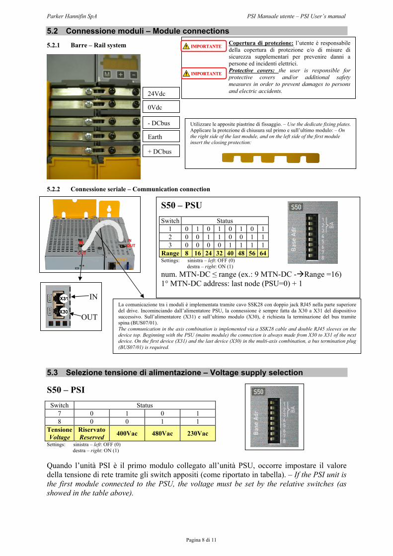
5.2 Connessione moduli – Module connections 5.2.1 Barre – Rail system
5.2.2 Connessione seriale – Communication connection
5.3 Selezione tensione di alimentazione – Voltage supply selection S50 – PSI
Switch Status 7 0 1 0 1 8 0 0 1 1
Tensione Voltage
Riservato Reserved 400Vac 480Vac 230Vac
Settings: sinistra – left: OFF (0) destra – right: ON (1)
Quando l’unità PSI è il primo modulo collegato all’unità PSU, occorre impostare il valore della tensione di rete tramite gli switch appositi (come riportato in tabella). – If the PSI unit is the first module connected to the PSU, the voltage must be set by the relative switches (as showed in the table above).
24Vdc
- DCbus
Earth
+ DCbus
0Vdc
Utilizzare le apposite piastrine di fissaggio. – Use the dedicate fixing plates. Applicare la protezione di chiusura sul primo e sull’ultimo modulo: – On the right side of the last module, and on the left side of the first module insert the closing protection:
INOUT
IN
OUT
Copertura di protezione: l’utente è responsabile della copertura di protezione e/o di misure di sicurezza supplementari per prevenire danni a persone ed incidenti elettrici. Protective covers: the user is responsible for protective covers and/or additional safety measures in order to prevent damages to persons and electric accidents.
IIMMPPOORRTTAANNTTEE
IIMMPPOORRTTAANNTTEE
S50 – PSU Switch Status
1 0 1 0 1 0 1 0 1 2 0 0 1 1 0 0 1 1 3 0 0 0 0 1 1 1 1
Range 8 16 24 32 40 48 56 64Settings: sinistra – left: OFF (0)
destra – right: ON (1) num. MTN-DC ≤ range (ex.: 9 MTN-DC - Range =16) 1° MTN-DC address: last node (PSU=0) + 1
IN
OUT
La comunicazione tra i moduli è implementata tramite cavo SSK28 con doppio jack RJ45 nella parte superiore del drive. Incominciando dall’alimentatore PSU, la connessione è sempre fatta da X30 a X31 del dispositivo successivo. Sull’alimentatore (X31) e sull’ultimo modulo (X30), è richiesta la terminazione del bus tramite spina (BUS07/01). The communication in the axis combination is implemented via a SSK28 cable and double RJ45 sleeves on the device top. Beginning with the PSU (mains module) the connection is always made from X30 to X31 of the next device. On the first device (X31) and the last device (X30) in the multi-axis combination, a bus termination plug (BUS07/01) is required.
Parker Hannifin SpA PSI Manuale utente – PSI User’s manual
Pagina 9 di 11
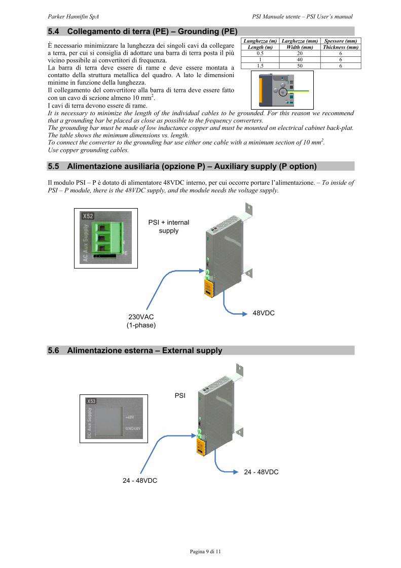
5.4 Collegamento di terra (PE) – Grounding (PE) È necessario minimizzare la lunghezza dei singoli cavi da collegare a terra, per cui si consiglia di adottare una barra di terra posta il più vicino possibile ai convertitori di frequenza. La barra di terra deve essere di rame e deve essere montata a contatto della struttura metallica del quadro. A lato le dimensioni minime in funzione della lunghezza. Il collegamento del convertitore alla barra di terra deve essere fatto con un cavo di sezione almeno 10 mm2. I cavi di terra devono essere di rame. It is necessary to minimize the length of the individual cables to be grounded. For this reason we recommend that a grounding bar be placed as close as possible to the frequency converters. The grounding bar must be made of low inductance copper and must be mounted on electrical cabinet back-plat. The table shows the minimum dimensions vs. length. To connect the converter to the grounding bar use either one cable with a minimum section of 10 mm2. Use copper grounding cables. 5.5 Alimentazione ausiliaria (opzione P) – Auxiliary supply (P option) Il modulo PSI – P è dotato di alimentatore 48VDC interno, per cui occorre portare l’alimentazione. – To inside of PSI – P module, there is the 48VDC supply, and the module needs the voltage supply.
230VAC(1-phase)
48VDC
PSI + internal supply
5.6 Alimentazione esterna – External supply
24 - 48VDC24 - 48VDC
PSI
Lunghezza (m) Larghezza (mm) Spessore (mm) Length (m) Width (mm) Thickness (mm)
0.5 20 6 1 40 6
1.5 50 6

Parker Hannifin SpA PSI Manuale utente – PSI User’s manual
Pagina 10 di 11
5.7 Connessioni Motornet DC – Motornet DC connections
N.B.: l’uso del cavo ibrido limita sia la tensione, a 600VDC, che la corrente, per la sezione applicabile ai connettori. – The Hybrid cable limits the voltage, up to 600VDC, and the current, in according to the max section of the connectors.
+
PS
UPS
I
Collegam
enti tramite cavo ibrido
Hybrid cable version
Cavo ibrido:
Hybrid cable:
Service BUS +
PO
WE
R
24 - 48VD
Cor
230VA
C(1-phase)

MI PSI 0 09/10 IE