BLU 3000.1 PR / MD BLU 4000.1 PR / MD tecniche per...pag.4 A LB 382 BLU 3000.1 - 4000.1 PR/MD CICLO...
60
BLU 3000.1 PR / MD BLU 4000.1 PR / MD LB382 09.05.2006 A BRUCIATORI A GAS PROGRESSIVI E MODULANTI B MODULATING AND PROGRESSIVE GAS BURNERS C BRULEURS GAZ PROGRESSIVES ET MODULANTS D QUEMADOR DE GAS PROGRESIVOS EN MODULANTE
Transcript of BLU 3000.1 PR / MD BLU 4000.1 PR / MD tecniche per...pag.4 A LB 382 BLU 3000.1 - 4000.1 PR/MD CICLO...

BLU 3000.1 PR / MDBLU 4000.1 PR / MD
LB38209.05.2006
A BRUCIATORI A GAS PROGRESSIVI E MODULANTIB MODULATING AND PROGRESSIVE GAS BURNERSC BRULEURS GAZ PROGRESSIVES ET MODULANTSD QUEMADOR DE GAS PROGRESIVOS EN MODULANTE

pag.2
A LB 382 BLU 3000.1 - 4000.1 PR/MD
Caratteristiche tecniche BLU 3000.1PR/MD BLU 4000.1PR/MD
Potenza termica max. kW 3000 3900kcal/h 2.586.000 3.362.000
Potenza termica min. kW 630 875kcal/h 543.100 754.300
Pressione gas metano mbar 40÷300 40÷300Pressione GPL mbar 37÷150 37÷150Tensione di alim. TRIFASE + neutro , 50 Hz V 230 / 400 230 / 400Motore kW 5,5 7,5Giri / minuto del motore N° 2800 2800Combustibile : P.c.i. gas metano = 35,9 Mj / Nm3 = 8.570 kcal / Nm3
P.c.i. GPL 22.260 kcal / Nm3
Con
trop
ress
ione
in c
amer
a di
com
bust
ione
Potenza
CAMPO DI LAVORO DEI BRUCIATORI
MODELS A B C D D1 E F G H I L M N OBlu 3000.1 941 448 493 330 530 780 290 466 280 315 315 M16 195 250Blu 4000.1 941 448 493 365 565 780 320 466 280 315 315 M16 195 250
D= Short head D1= Long head
IM
L
E D - D1
F
CBA
10
23
I
O
GH
N
O
DIMENSIONI DI INGOMBRO
mbar
1500 2000 2500 3000 3500 4000
10
12
14
16
1000
0
2
4
6
8
500
BLU 4000.1
kW
kcal/hx 1000
500 1000 1500 2000 2500 3000 3500
BLU 3000.1

pag.3
LB 382 BLU 3000.1 - 4000.1 PR/MD A
ALLACCIAMENTO ELETTRICOTutti i bruciatori sono collaudati a 400 V 50 Hz trifase per i motori e 230V 50 Hz monofase con neutro per gli ausiliari.Se fosse necessario alimentare il bruciatore a 230 V 50 Hz trifase senza neutro, eseguire le modifiche necessarie riferendosi allo spe-cifico schema elettrico del bruciatore e controllare che il relé termico sia entro il campo di assorbimento del motore.Accertare inoltre il corretto senso di rotazione del motore del ventilatore.
ALLACCIAMENTO ALLA LINEA GASAllacciato il bruciatore alla tubazione del gas è necessario assicurarsi che quest’ultima sia a tenuta perfetta. Assicurarsi pure che ilcamino non sia ostruito. Aperto il rubinetto del gas sfiatare con prudenza la tubazione attraverso l’apposita presa di pressione equindi controllare il valore della pressione con un manometro idoneo. Dare tensione all’impianto e regolare i termostati alla tempe-ratura desiderata. Alla chiusura dei termostati, il dispositivo di controllo fughe gas effettua una prova di tenuta delle valvole; Al ter-mine della prova il bruciatore riceve il consenso per effettuare il ciclo di avviamento.
Prima di accendere il bruciatore, assicurarsi che sia montato correttamente. Controllare i collegamenti elettrici secondo i diagrammie le tubazioni dell’impianto. Prima del collegamento elettrico assicurarsi che il voltaggio corrisponda ai dati indicati nella targhettacaratteristiche.Il diagramma del collegamento elettrico e il ciclo di avviamento sono illustrati separatamente. Per collegare l’apparec-chiatura al bruciatore, vedere lo schema. Prestare particolarmente attenzione al collegamento del neutro e della fase: non scambiarlimai. Controllare il collegamento terra dell’impianto. Nei motori trifase controllare il senso di rotazione del motore (vedere freccia).Sfiatare l’aria e le impurità della tubazione del gas. Controllare che la pressione del gas sia nei limiti indicati nella targhetta. Questocontrollo deve essere effettuato con un manometro gas nell’apposita presa di pressione prevista sul bruciatore. Si avvia il motore edinizia la preventilazione. Il motoriduttore porta la serranda dell’aria alla massima apertura in circa 30 secondi. Quando il motori-duttore é completamente aperto, un segnale all’apparecchiatura elettronica di controllo avvia un ciclo di preventilazione di circa 66secondi. Alla fine di questa preventilazione, il motoriduttore porta la serranda in bassa fiamma permettendo l’accensione del brucia-tore alla minima portata. Contemporaneamente il trasformatore di accensione viene alimentato e dopo tre secondi (pre-accensione)vengono alimentate le valvole del gas. A questo punto la valvola a farfalla regola la portata del gas nella testa di combustione. Duesecondi dopo l’apertura delle valvole, il trasformatore é escluso dal circuito. In caso di mancanza di accensione il bruciatore va inblocco entro due secondi. Il bruciatore si trova acceso alla minima potenza (circa 30% della massima potenza). Lo strumentomodulatore farà aprire il servomotore alla massima potenza o lo fermerà alla potenza intermedia richiesta dall’impianto. L’aperturadel servomotore farà aprire gas ed aria in modo proporzionale per avere sempre a tutte le portate (30%-100%) una combustioneottimale. Al termine del funzionamento il servomotore si porta in posizione di chiusura.
AVVIAMENTO DEL BRUCIATORE
EC
CE
SS
O D
'AR
IA (
%)
FA
TT
OR
E D
'AR
IA
1010 20 30 40 50 60
7080
90100 200 300 400
500600
700800
9001000
1,1
1,15
1,21,2 1,2
1,25
1,3
15
20
25
30
POTENZA UTILE NOMINALE (kW)
2000 30005000
40006000
MetanoCO2 9,6%
CO <100 ppm
REGOLAZIONE DELLA COMBUSTIONEATTENZIONE : per ottenere una corretta regolazione della combustione e della portata termica occorre effettuare l'analisi dei fumi, ser-vendosi degli appositi strumenti. La regolazione della combustione e della portata termica va eseguita contemporaneamente ad una analisidei prodotti della combustione, assicurandosi che i valori riscontrati siano corretti, e, in ogni caso, rispondenti alle normative di sicurezzavigenti. A tal proposito vedere la tabella e la figura sottostanti.TALE OPERAZIONE DEVE ESSERE ESEGUITA DA PERSONALE PROFESSIONALMENTE QUALIFICATO ED AUTO-RIZZATO DALLA ECOFLAM SPA .
VALORI DI RIFERIMENTO CONSIGLIATI
GPLCO2 11,7%
CO <50 ppm

pag.4
A LB 382 BLU 3000.1 - 4000.1 PR/MD
CICLO DI FUNZIONAMENTO DELL’APPARECCHIATURA LANDIS & STAEFA MOD. LFL1.622
Rivelazionedi fiamma
Spia di blocco
Valvola gas
Serranda aria
Farfalla gas
Trasformatoredi accensione
Pressostato aria
Motore ventilatore
Pressostato gas
0min
100%
t1 t2
t4
t3
t6t5 Rif. descrizione
t1 tempo di attesa della conferma della pressione dell'aria 8"
t2 tempo di preventilazione 66" t3 tempo di sicurezza 2" t4 tempo di preaccensione 4" t5 tempo per il consenso di funzionam.
alla minima potenza della valvola di lavoro del combustibile 10"" t6 tempo per il consenso di funzionam.
alla massima potenza della valvola dilavoro del combustibile 10"
Ciclo di funzionamento normaleCiclo di funzionamento
in mancanza di fiamma all'accensionet1 t2
t4
t3
Consensomin./max. potenza
durata
L’apparecchiatura controllo fiamma fa partire il ventilatore del bruciatore per effettuare il prelavaggio della camera di combustione,controllando la presione dell’aria di ventilazione tramite il pressostato aria. Al termine della preventilazione entra in funzione il tra-sformatore di accensione generando una scintilla tra gli elettrodi e contemporaneamente si aprono le valvole del gas (valvole gas disicurezza VS e valvola di lavoro VL). La sicurezza totale in caso di mancata accensione o di spegnimento accidentale viene affidata auna sonda di rivelazione che interviene mandando in blocco l’apparecchiatura entro il tempo di sicurezza. Nel caso di mancanza digas o di un calo notevole di pressione il pressostato gas di minima provvede ad interrompere il funzionamento del bruciatore.
SERVOCOMANDO ARIA LANDIS & STAEFA SQM 50.481A2 Togliere il coperchio per accedere alle camme di regolazione. Lo spostamento delle camme va effettuato con l’ausiliodell’apposita chiavetta in dotazione. Descrizione :
I - Camma di regolazione posizione di apertura in potenza max.II - Camma di regolazione della posizione serranda allo spegnimento.III - Camma di regolazione posizione di apertura in potenza min.IV - Camma di regolazione posizione di apertura in bassa fiamma.V - Camma non usataVI - Camma non usataVII - Camma non usataVIII- Camma non usata
Camma VIII non usata

pag.5
LB 382 BLU 3000.1 - 4000.1 PR/MD A
CALCOLO PORTATA BRUCIATOREPer calcolare la portata in kW del bruciatore, procedere nel modo seguente :Controllare al contatore la portata in litri del gas e il tempo in secondi della lettura.
Procedere al calcolo secondo la formula : e x f = kWsec
e = Litri gassec = Tempo in secondi G20 = 34,02G25 = 29,25G30 = 116G31 = 88
f
REGOLAZIONE DELLA PORTATA ARIA E GAS
+
--
Part. 1
Part. 2
Part. 3
-
+
-COMMUTATORE
0
AUTO
0 = bloccaggio degli apparati per il funzionamento in una posizione intermadia = funzionamento alla massima potenza = funzionamento alla minima potenza AUTO = funzionamento automatico
REGOLAZIONE DELLA POTENZA MINIMA DEL GASPosizionare il commutatore che si trova sulla mostrina in posizione 2 e agire come segue:Per regolare la portata minimo del gas agire con la chiave a brugola sulla vite della camma e modificare l’angolo dellaserranda gas della valvola a farfalla.
REGOLAZIONE DELLA POTENZA MASSIMA DEL GASPosizionare il commutatore che si trova sulla mostrina in posizione 1 e agire come segue:Per regolare la portata massimo del gas agire sull’elettrovalvola di regolazione fino a ottenere il valore corretto per la cal-daia.
REGOLAZIONE DELLA PORTATA MASSIMA DELL’ARIA Svitare la vite di fissaggio dell’asta e mettere la stessa nella posizione corretta.Alla fine della regolazione richiudere la vite dell’asta.
REGOLAZIONE DELLA PORTATA INTERMEDIA DEL GASAzionare il servomotore con il commutatore (aperto/chiuso) e posizionarlo nella posizione 0 per fermarlo. Per la regola-zione, agire come segue. Ripetere i passaggi per gli altri punti delle camme.Regolazione della portata intermediaria del gas (vedere immagine 3):Con una chiave a brugola modificare la posizione della lamina guida della camma, chiudendo la portata aumenta,aprendo la portata diminuisce.

pag.6
A LB 382 BLU 3000.1 - 4000.1 PR/MD
TARATURA DEL PRESSOSTATO GAS DI MINIMA PRESSIONE- svitare le viti I e L e togliere il coperchio M- posizionare il regolatore N ad un valore pari al 60% della pressione nominale di alimentazione gas
(es.: per gas metano press. nominale =20 mbar; regolatore posizionato al valore 12 mbar; perG.P.L. pressione nominale G30-G31 30/37 mbar regolatore posizionato al valore di 18 mbar)
- rimontare il coperchio M e riavvitare le viti I e L
TARATURA DEL PRESSOSTATO ARIA- svitare le viti A e B e togliere il coperchio C- tarare il pressostato aria al minimo, ruotando il regolatore D in posizione 1.- avviare il bruciatore e impostare il funzionamento in 1° stadio (1 fiamma).- verificare la corretta combustione.- con l’ausilio di un cartoncino ostruire progressivamente il condotto di aspirazione dell’aria
fino ad ottenere un aumento del valore di CO2 di circa 0,5÷0,8 %, oppure, se si dispone diun manometro collegato alla presa di pressione E, fino ad ottenere una diminuzione di 0,1mbar (~10 mm C.A.).
- aumentare lentamente il valore di taratura del pressostato, fino a causare lo spegnimento inblocco del bruciatore.
- togliere l’ostruzione al condotto di aspirazione aria e rimontare il coperchio C.- ripristinare il funzionamento del bruciatore agendo sul pulsante di sblocco dell’apparecchiatura.
N.B.) - La pressione misurata alla presa E deve rientrare nel campo di lavoro del pressostato. Se ciònon fosse. allentare il dado dibloccaggio alla base della vite F ed agire gradualmente sulla stessa; in senso orario per diminuire la pressione, antiorario peraumentarla. Al termine della regolazione, ribloccare il dado di bloccaggio.
2,55
10 15
50
25
35
30
4045
20
0,4
0,6 0,9
3,0
1,5
2,1
1,8
2,42,7
1,2
I
L
MN
A
B
CD
E
F
GH
pressostato gas
pressostato aria
REGOLAZIONE DELLA COMBUSTIONEATTENZIONE: Ai fini di una corretta regolazione della combustione e della portata termica, queste vanno eseguitecontemporaneamente ad una analisi dei fumi, da effettuarsi con strumenti appositi, controllamndo che i valori riscon-trati siano corretti e rispondenti alle normative di sicurezza in vigore. Le operazioni di rgolazione debbono essere effet-tuate da personale qualificato ed autorizzato dalla Ecoflam S.p.A.
REGOLAZIONE TESTA DI COMBUSTIONE
4 mm
7 mmElettrodo di accensione
Elettrodo di rivelazione
""
7 mm
POSIZIONE DEGLI ELETTRODI
+-

pag.7
LB 382 BLU 3000.1 - 4000.1 PR/MD A
24
min. 6 µA
LANDIS LFL1.622Microamperometro fondo scala 50 µA
CONTROLLO SISTEMA DI RILEVAZIONE FIAMMAIl controllo della corrente di ionizzazione si effettua inse-rendo un microamperometro con fondo scala di 50 µA(corrente continua) in serie all'elettrodo di rivelazione.Un errato posizionamento dell'elettrodo può comportareuna riduzione della corrente di ionizzazione e determina-re un arresto di sicurezza del bruciatore dovuto a man-canza di rivelazione di fiamma.In tal caso verificare il corretto posizionamento dell'elet-trodo, il collegamento elettrico di questo e la messa aterra del bruciatore. Normalmente il valore della correntedi ionizzazione è >20 µA.
SMONTAGGIO TESTA
ABCD
A- interruttore acceso / spento
B- portafusibile
C- selettore:
0 = bloccaggio degli apparati per il funzionamento
in una posizione intermadia
= funzionamento alla massima potenza
= funzionamento alla minima potenza
AUTO = funzionamento automatico
D- lampada di blocco relé termico
E - lampada di funzionamento F - pulsante di sblocco
E
F
0
AUTO
0I
DESCRIZIONE DEL PANNELLO DI COMANDO DEI BRUCIATORI

pag.8
A LB 382 BLU 3000.1 - 4000.1 PR/MD
REGOLATORE A MICROPROCESSORE RWF 40
Display:ingresso analogico
1 (valore reale)
Display: setpoint SP1
Diminuisce valore
Tasto programmazione
Funzionamento manuale
Contatto ausiliario
Aumenta valore
Tasto USCITA
FunzionamentoBruciatore
Diminuzione potenzaCHIUDI / 1 Stadio
Aumento potenzaAPRI / 2 Stadio
Funzionamento bistadio
Significato del display e dei tasti del regolatore a microprocessore RWF 40Nella figura viene visualizzato il display di base,
che indica il valore reale ed il setpointimpostato, é importante inoltre
il significato di ogni tasto e diogni led di segnalazione
Livello configurazione
Livello utente
Display normale
Livello parametri
PGM
PGM
PGM
PGM PGMPGM
PGM PGM
PGM PGM
min 2s
min 2s
min 2s
Exit
LIVELLI DI PROGRAMMAZIONE

pag.9
LB 382 BLU 3000.1 - 4000.1 PR/MD A
IMPOSTAZIONI PARAMETRIAll’accensione del bruciatore tutti i dislay del regolatore sono accesi, il display del setpoint lampeggerà per circa 10 sec. Il valorevisualizzato nel dislay superiore (rosso) indica il valore reale. Il valore visualizzato nel dislay inferiore (verde) indica il valore del set-point impostato.REGOLAZIONE DEL SETPOINT Per la regolazione del setpoint bisogna agire come segue.: ---- Con il pulsante PGMPGM si accede al livello utente, apparirà nel display dibase SP1*. - Modificare il valore del setpoint SP1 agendo sui tasti �e �. ---- Dopo 2 sec. il valore impostato viene automaticamentememorizzato. ---- Per ritornare nel display di base premere il pulsante EXITEXIT.** Il valore di SP1 dipende dal valore pre impostato nel livello di configurazione C111IMPOSTAZIONE PARAMETRI PIDI parametri PID sono già pre impostati in fabbrica su valori medi standard. E’ possibile adattare il funzionamento del regolatore infunzione dell’impianto, attivando la funzione Autoadattamento “tunE”. Il regolatore provvederà a impostare i parametri PID inautomatico. Per attivare la funzione “tunE” bisogna agire come segue: ---- Con il bruciatore in funzione avviare l’autoadattamentocon il pulsante PGM PGM + �. ---- Nel dislay apparirà la scritta “tunE*” lampeggiante. ---- Quando la scritta “tunE” termina il lampeggiol’autoadattamento è terminato. ---- Confermare i parametri calcolati tenendo premendo per 2 sec il tasto �. ** La funzione “tunE” non è attuabile in funzionamento manuale, o/a bruciatore spento.I parametri PID possono essere coretti manualmente dal livello parametri agendo sulla banda proporzionale Pb1, tempodell’azione derivata dt e il tempo dell’azione integrale rt. Per modificare i parametri Pb1, dt, rt, bisogna agire come segue: ---- Con il pulsante PGMPGM si accede al livello parametri. ---- Si passada un parametro al successivo premendo sempre PGMPGM. ---- Quando nel dislay apparirà la scritta Pb1. ---- Si aumenta o diminuisce ilvalore premendo i pulsanti �e �. ---- Confermare i parametri modificati premendo PGMPGM, se ciò non avviene il valore viene memo-rizzato automaticamente dopo 2 sec. ---- Con il pulsante PGMPGM si accede al successivo parametro. ---- Quando nel display apparirà lascritta dt si ripetono le istruzioni precedenti. ---- Con il pulsante PGMPGM si accede al successivo parametro. ---- Quando nel displayapparirà la scritta rt si ripetono le istruzioni precedenti. ---- Per ritornare nel display di base premere il pulsante EXITEXIT.REGOLAZIONE DIFFERENZIALE DI ACCENSIONE E SPEGNIMENTO.Il regolatore permette di impostare un differenziale di commutazione regolabile che stabilisce i valori di accensione e spegni-mento del bruciatore. Con HYS1 si intende il limite inferiore di accensione sotto tale soglia il regolatore commuta il bruciatorealla massima potenza, con HYS3 si intende il limite superiore di spegnimento superata tale soglia il regolatore spegne il brucia-tore. Per impostare HYS1 e HYS3 bisogna agire come segue: ---- Con il pulsante PGMPGM si accede al livello parametri. ---- Si passa daun parametro al successivo premendo sempre PGMPGM. ---- Quando nel dislay apparirà la scritta HYS1 (differenziale di accensione bru-ciatore II stadio). ---- Si aumenta o diminuisce il valore premendo i pulsanti �e �. ---- Confermare i parametri modificati premendoPGMPGM, se ciò non avviene il valore viene memorizzato automaticamente dopo 2 sec. ---- Con il pulsante PGMPGM si accede al successivoparametro. ---- Quando nel display apparirà la scritta HYS2 (differenziale di spegnimento bruciatore II stadio) si ripetono le istruzio-ni precedenti. ---- Con il pulsante PGMPGM si accede al successivo parametro. ---- Quando nel display apparirà la scritta HYS3 (differen-ziale superiore di spegnimento) si ripetono le istruzioni precedenti.---- Per ritornare nel display di base premere il pulsante EXITEXIT.FUNZIONAMENTO MANUALE / AUTOMATICOPer accedere alla funzionalità di funzionamento”MANUALE” premere il tasto EXIT EXIT per almeno 5 secondi.. Il funzionamentomanuale può essere inserito solamente quando il bruciatore è in funzione, si disattiva automaticamente quando il bruciatore si spe-gne. Quando è acceso il LED sopra il simbolo della mano il regolatore sta lavorando in manuale, si può cosi modificare la posizionedel servocomando con i tasti �e �. I LED accesi sul fronte del regolatore indicano se è attivo il comando APRI o CHIUDI delservocomando. Premendo il tasto � il servocomando si APRE. Premendo il tasto � il servocomando si CHIUDE. Per passare infunzionamento automatico bisogna premere il pulsante EXITEXIT per 5 sec. il LED sopra il simbolo della mano si spegne ed il regola-tore si trova ora in automatico.
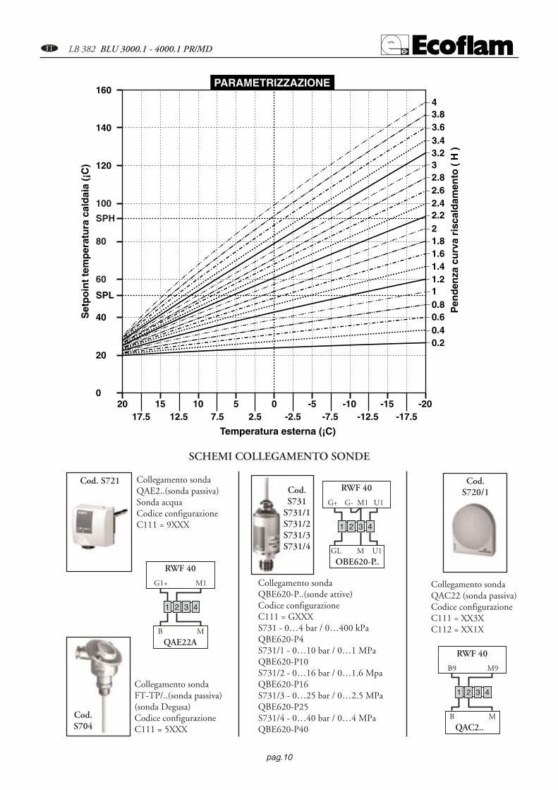
COMPENSAZIONE CLIMATICA. Il regolatore RWF40 può essere configurato con il setpoint dipendente alla sonda esterna. Perché ciò avvenga bisogna impostare ilregolatore come segue: ---- Collegare la sonda desiderata come da schema elettrico. ---- Modificare impostazioni regolatore. Consonda esterna bisogna impostare il regolatore come segue: ---- Con il pulsante PGMPGM si accede al livello configurazione, quando neldislay apparirà la scritta C111 (XXXX), si utilizza il pulsante � finche si accede alla seconda cifra (XXXX), con il tasto � si impo-sta il tipo di sonda(XX3X). ---- Confermare i parametri modificati premendo PGMPGM , se ciò non avviene automaticamente dopo 2sec. il valore viene memorizzato. ---- Con il pulsante PGMPGM si accede al livello configurazione, quando nel dislay apparirà la scrittaC112 (XXXX), si utilizza il pulsante �finche si accede alla seconda cifra (XXXX),con il tasto � si imposta il tipo di sonda(XX1X). ---- Confermare i parametri modificati premendo PGMPGM, se ciò non avviene automaticamente dopo 2 sec. il valore viene memorizza-to. ---- Per ritornare nel display di base premere il pulsante EXITEXIT.Per l’impostazione della curva di riscaldamento il regolatore va impostato come segue:---- Con il pulsante PGMPGM si accede al livello parametri. ---- Si passa da un parametro al successivo premendo sempre PGMPGM.---- Quando nel dislay apparirà la scritta H (pendenza della curva di riscaldamento). ---- Si aumenta o diminuisce il valore premendo ipulsanti � e �. ---- Confermare i parametri modificati premendo PGMPGM, se ciò non avviene automaticamente dopo 2 sec. il valoreviene memorizzato. ---- Per ritornare nel display di base premere il pulsante EXITEXIT.
pag.10
A LB 382 BLU 3000.1 - 4000.1 PR/MD
SPH
60
80
100
0
20
40
SPL
120
140
160
20 15 10 5 0 -20-15-10-517.5 12.5 7.5 2.5 -2.5 -17.5-12.5-7.5
0.20.40.60.811.21.41.61.822.22.42.62.833.23.43.63.84
Temperatura esterna (¡C)
Set
po
int
tem
per
atu
ra c
ald
aia
(¡C
)
Pen
den
za c
urv
a ri
scal
dam
ento
( H
)
PARAMETRIZZAZIONE
Cod.S704
Cod. S721Cod.S731
S731/1S731/2S731/3S731/4
Cod.S720/1
Collegamento sondaQAE2..(sonda passiva)Sonda acquaCodice configurazioneC111 = 9XXX
Collegamento sondaFT-TP/..(sonda passiva)(sonda Degusa)Codice configurazioneC111 = 5XXX
Collegamento sonda QBE620-P..(sonde attive)Codice configurazione C111 = GXXXS731 - 0…4 bar / 0…400 kPa QBE620-P4 S731/1 - 0…10 bar / 0…1 MPa QBE620-P10 S731/2 - 0…16 bar / 0…1.6 Mpa QBE620-P16 S731/3 - 0…25 bar / 0…2.5 MPa QBE620-P25 S731/4 - 0…40 bar / 0…4 MPa QBE620-P40
Collegamento sondaQAC22 (sonda passiva)Codice configurazione C111 = XX3XC112 = XX1X
1 2 3 4
RWF 40
B M
G1+ M1
QAE22A
1 2 3 4
RWF 40
B M
B9 M9
QAC2..
1 2 3 4
RWF 40
GL M
G+ M1
OBE620-P..U1
G- U1
SCHEMI COLLEGAMENTO SONDE

pag.11
LB 382 BLU 3000.1 - 4000.1 PR/MD A
- Comportamento - Nel caso si abbia: nel dislay del valore reale il numero 1999 lampeggiante, e nel dislay del setpoint il valore del setpoint.
- Causa - Il valore reale non viene misurato. Significa che è stato superato verso l’alto o verso il basso il campo di misura dell’ingresso analogico1 (valore reale).
- Rimedio - Verificare i collegamenti elettrici e lo stato della sonda. Nel caso di guastodella sonda, il regolatore non rivela il valore reale della grandezza controllata, ne consegue uno spegnimento automatico di sicurezza, una disattivazione dell’autoadattamento e la disattivazione del funzionamento manuale.Il contatto ausiliario risponde a seconda della configurazione del parametro C113.
- Comportamento - Nel caso si abbia: nel dislay del valore reale il numero 1999 lampeggiante, e nel dislay del setpoint venga indicato tA.
- Causa - La temperatura esterna non viene misurata. Significa che è stato superatoverso l’alto o verso il basso il campo di misura dell’ingresso analogico3 (valore reale).
- Rimedio - Verificare i collegamenti elettrici e lo stato della sonda. Nel caso di guasto della sonda, il regolatore non rivela il valore reale.
- Comportamento - Nel caso si abbia: nel dislay del valore reale il numero1999 lampeggiante, e nel dislay del setpoint venga indicato SP .E
- Causa - Il valore del setpoint esterno non viene misurato. Significa che è stato superato verso l’alto o verso il basso il campo di misura dell’ingresso analogico2 (valore reale).
- Rimedio - Verificare i collegamenti elettrici e il segnale del setpoint esterno.Nel caso di guasto della sonda, il regolatore non rivela il valore reale della grandezzacontrollata, ne consegue uno spegnimento automatico di sicurezza, una disattivazione dell’autoadattamento e la disattivazione del funzionamento manuale.
SEGNALAZIONE GUASTI / ANOMALIELAMPEGGIO DEI NUMERI SUL DISPLAY
Ingresso analogico 1 (valore reale)Pt1000, 2 fili, Landis & Staefa IEC 751
5FT-TP/...(sonda passiva)Ni1000, 2 fili, Landis & Staefa
9QAE2... (sonda passiva - sonda aqua)Segnale standard DC 0...10 V QBE620-P...(sonda attiva-sonda di pressione) G
INDICAZIONI CONFIGURAZIONE INGRESSI C111 - C112
Ingresso analogico 3 (temperatura esterna)Nessuna funzione (sonda non attiva) 0Sonda esterna Pt 1000, 2 fili,
1QAC22 (sonda passiva)
CONTATTO AUSILIARIO, TIPO DI REGOLATORE, SETPOINT “SP1”, BLOCCO C112. Configurazione parametri
Setpoint “SP1”Setpoint SP1 impostazione dati con tasti 0Setpoint SP1 dipendente dalla sonda esterna (configurare 1

pag.12
A LB 382 BLU 3000.1 - 4000.1 PR/MD
A
Inserire il regolatore RWF 40 nell’apposita apertura del cassetto elettrico (A). Inserire nelle fessure i tasselli ad incastro con le viti, quindi bloccarla al pannellodella cassetta per una corretta tenuta (B). Per aprire il regolatore fare pressione sul coperchio come indicato (C) e sollevare.
NEL CASO DI NECESSITÀ DI SOSTITUZIONE PROCEDERE COME INDICATO NELLE SOTTOSTANTI FIGURE A-B-C
B C
MANUTENZIONECONTROLLO ANNUALEIl controllo periodico del bruciatore (testa di combustione, elettrodi,ecc.) deve essere effettuato da personale autorizzato una o due volte all’anno a secondo dell’utilizzo. Prima di procedere al controllo per la manutenzione del bruciatore è consigliabile verificare lo stato generale del bruciatore e seguire le seguenti operazioni : - Togliere tensione al bruciatore (togliere la spina). - Chiudere il rubinetto di intercettazione gas. - Togliere il coperchio del bruciatore, pulire la ventola e l’aspirazione dell’aria. - Pulire la testa di combustione e controllare la posizione degli elettrodi. - Rimontare i pezzi. - Verificare la tenuta dei raccordi gas.- Verificare il camino. - Far ripartire il bruciatore. - Controllare i parametri della combustione.PRIMA DI OGNI INTERVENTO CONTROLLARE :- Che ci sia corrente elettrica nell’impianto e il bruciatore collegato. - Che la pressione del gas sia corretta e il rubinetto di intercettazione del gas aperto. - Che i sistemi di controllo siano regolarmente collegati. Se tutte queste condizioni sono soddisfatte , far partire il bruciatore premendo il pulsante di sblocco. Controllare il ciclo del bruciatore.IL BRUCIATORE NON SI AVVIA : - Controllare l’interruttore, i termostati, il motore, pressione gas.IL BRUCIATORE EFFETTUA LA PREVENTILAZIONE E AL TERMINE DEL CICLO VA IN BLOCCO :- Controllare la pressione dell’aria e la ventola. - Controllare il pressostato aria.IL BRUCIATORE EFFETTUA LA PREVENTILAZIONE E NON ACCENDE :- Verificare il montaggio e la posizione degli elettrodi. - Verificare il cavo di accensione. - Verificare il trasformatore di accensione. - Verificare l’apparecchiatura di sicurezza.IL BRUCIATORE SI ACCENDE E DOPO IL TEMPO DI SICUREZZA VA IN BLOCCO : - Controllare fase e neutro che siano collegati correttamente. - Controllare l’elettrovalvole del gas. - Controllare la posizione dell’elettrodo di rivelazione e la sua connessione. - Controllare l’elettrodo di rivelazione. - Controllare l’apparecchiatura di sicurezza.IL BRUCIATORE SI ACCENDE E DOPO QUALCHE MINUTO DI FUNZIONAMENTO VA IN BLOCCO :- Controllare il regolatore di pressione e il filtro gas. - Controllare la pressione del gas con un manometro. - Controllare il valore di rivelazione (min 6 µA).
pag.13
LB 382 BLU 3000.1 - 4000.1 PR/MD A
Parametro Display Valore impostato Valore impostato Valore impostato(sonda passiva) (sonda passiva) (sonda attiva)
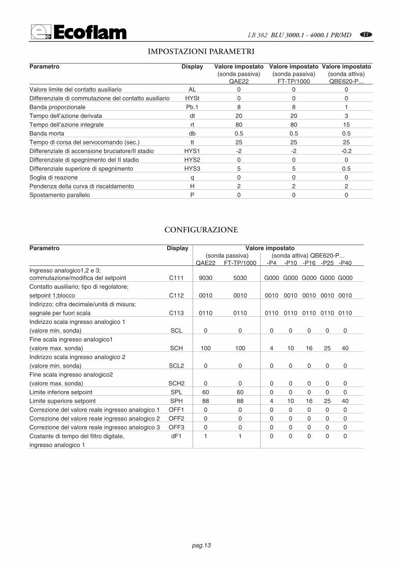
QAE22 FT-TP/1000 QBE620-P...Valore limite del contatto ausiliario AL 0 0 0Differenziale di commutazione del contatto ausiliario HYSt 0 0 0Banda proporzionale Pb.1 8 8 1Tempo dell’azione derivata dt 20 20 3Tempo dell’azione integrale rt 80 80 15Banda morta db 0.5 0.5 0.5Tempo di corsa del servocomando (sec.) tt 25 25 25Differenziale di accensione bruciatore/II stadio HYS1 -2 -2 -0.2Differenziale di spegnimento del II stadio HYS2 0 0 0Differenziale superiore di spegnimento HYS3 5 5 0.5Soglia di reazione q 0 0 0Pendenza della curva di riscaldamento H 2 2 2Spostamento parallelo P 0 0 0
IMPOSTAZIONI PARAMETRI
Parametro Display Valore impostato(sonda passiva) (sonda attiva) QBE620-P...
QAE22 FT-TP/1000 -P4 -P10 -P16 -P25 -P40Ingresso analogico1,2 e 3; commutazione/modifica del setpoint C111 9030 5030 G000 G000 G000 G000 G000Contatto ausiliario; tipo di regolatore;setpoint 1;blocco C112 0010 0010 0010 0010 0010 0010 0010Indirizzo; cifra decimale/unità di misura;segnale per fuori scala C113 0110 0110 0110 0110 0110 0110 0110Indirizzo scala ingresso analogico 1(valore min. sonda) SCL 0 0 0 0 0 0 0Fine scala ingresso analogico1(valore max. sonda) SCH 100 100 4 10 16 25 40Indirizzo scala ingresso analogico 2(valore min. sonda) SCL2 0 0 0 0 0 0 0Fine scala ingresso analogico2(valore max. sonda) SCH2 0 0 0 0 0 0 0Limite inferiore setpoint SPL 60 60 0 0 0 0 0Limite superiore setpoint SPH 88 88 4 10 16 25 40Correzione del valore reale ingresso analogico 1 OFF1 0 0 0 0 0 0 0Correzione del valore reale ingresso analogico 2 OFF2 0 0 0 0 0 0 0Correzione del valore reale ingresso analogico 3 OFF3 0 0 0 0 0 0 0Costante di tempo del filtro digitale, dF1 1 1 0 0 0 0 0ingresso analogico 1
CONFIGURAZIONE

pag.14
B LB 382 BLU 3000.1 - 4000.1 PR/MD
Technical data BLU 3000.1 PR/MD BLU 4000.1 PR/MD
Thermal power max. kW 3000 3900kcal/h 2.586.000 3.362.000
Thermal power min. kW 630 875kcal/h 543.100 754.300
Natural gas pressure mbar 40÷300 40÷300LPG pressure mbar 37÷150 37÷150Voltage , 50 Hz V 230 / 400 230 / 400Motor kW 5,5 7,5Rpm N° 2800 2800Fuel : P.c.i. Natural gas = 35,9 Mj / Nm3 = 8.600 kcal / Nm3
P.c.i. GPL 22.260 kcal / Nm3
MODELS A B C D D1 E F G H I L M N OBlu 3000.1 941 448 493 330 530 780 290 466 280 315 315 M16 195 250Blu 4000.1 941 448 493 365 565 780 320 466 280 315 315 M16 195 250
D= Short head D1= Long head
IM
L
E D - D1
F
CBA
10
23
I
O
GH
N
O
OVERALL DIMENSIONS
com
bu
stio
n c
ham
ber
pre
ssu
re
capacity
OPERATING RANGE OF THE BURNERSmbar
1500 2000 2500 3000 3500 4000
10
12
14
16
1000
0
2
4
6
8
500
BLU 4000.1
kW
kcal/hx 1000
500 1000 1500 2000 2500 3000 3500
BLU 3000.1

pag.15
LB 382 BLU 3000.1 - 4000.1 PR/MD B
ELECTRICAL CONNECTIONSAll burners factory tested at 400 V 50 Hz three-phase for motors and 230 V 50 Hz monophase with neutral for auxiliary equip-ment. If mains supply is 230 V 50 Hz threephase withuot neutral, change position of connectors on burner as in fig. Protect burnersupply line with safety fuses and any other devices required by safety standards obtaining in the country in question.
CONNECTION TO THE GAS PIPELINEOnce connected the burner to the gas pipeline, it is necessary to control that this last is perfectly sealed. Also verify that the chimneyis not obstructed. Open the gas cock and carefully bleed the piping through the pressure gauge connector, then check the pressurevalue trough a suitable gauge. Power on the system and adjust the thermostats to the desired temperature. When thermostats close,the sealing control device runs a seal test of valves; at the end of the test the burner will be enabled to run the start-up sequence.
BURNER START-UPOnce connected the burner to the gas pipe make sure that there are no leakages. Air bleed the pipe through the pressure gaugefixing point and check the pressure with a pressure gauge . Turn the thermostats to the desired temperature. PRELIMINARY CHECKS - Before starting up the boiler check the following: - gas type and feed pressure; - gas valves closed;- the seals in the pipe fittings; - gas pipe breather and input pressure; - that the cable complies with the diagram and the phase andneutral wires correspond; - that the burner shuts down when the boiler thermostat opens;- the seal of the boiler furnace which pre-vents air from entering; - the seal on the flue-boiler pipe fitting; - the condition of the flue (sealed, free from blockage, etc ).If allthese conditions are present, start the burner. The control device starts the motor to carry out prewashing of the combustion cham-ber. During this prewash period (about 30 seconds) the device checks that air pressure is correct via the air pressure switch. At theend, it supplies power to the transformer and opens the gas valves. The flame must be lit and stabilize within 3 seconds, which isthe device's safety time limit. Check to ensure the flame is lit before placing any control instrument in the flue. Adjust and checkthe gas flow necessary for the boiler at the meter. Adjust the air flow according to the gas flow to obtain correct combustion.
ADJUSTING THE COMBUSTION PROCESSIMPORTANT: to obtain the right adjustment of the combustion and thermal capacity it is important to analyze the reducts ofcombustion with the aid of suitable instruments. The combustion and thermal capacity adjustment is done simultaneously,together with the analysis of the products of combustion, making sure that the measured values are suitable and that they complywith current safety standards. On this matter, please refer to the table and figure below.THESE OPERATIONS MUST BE DONE BY PROFESSIONALLY-QUALIFIED TECHNICIANS.
AIR
EX
CE
SS
(%
)
AIR
FA
CT
OR
THERMAL POWER (kW)
1010 20 30 40 50 60
7080
90100 200 300 400
500600
700800
9001000
1,1
1,15
1,21,2 1,2
1,25
1,3
15
20
25
30
2000 30005000
40006000
Natural GasCO2 9,6%CO <50 ppm
LPGCO2 11,7%
CO <50 ppm

pag.16
B LB 382 BLU 3000.1 - 4000.1 PR/MD
LANDIS & STAEFA, Model LFL1.622 OPERATING CYCLE
The control box starts the burnerfan, to carry out the prepurging ofthe combustion chamber, andcheks the vent air pressure throu-gh the air pressure switch. At theend of prepurging, the ignitiontransformer cuts-in and generatesa spark between the electrodes. Atthe same time the two gas valvesopen (Vs safety valve and Vl working valve). The total safety, in case of missed ignition or casual burner's flame-out,is granted by a ionisation probe which cuts-in and sets the burner shutdown within the safety time. In case of gaslack or a major pressure drop, the minimum air pressure switch shuts down the burner.
Ref. Descriptiont1 Duration Waiting time for confirmationt2 of air pressuret3 Preventilation timet4 Safety timet5 Pressurizing time
Time for enabling operation of the main gas valve on minimum capacity
t6 Time for enabling operation of the main gas valve on maximum capacity
Duration
8”66”2”4”
10”
10”
Rivelazionedi fiamma
Spia di blocco
Valvola gas
Serranda aria
Farfalla gas
Trasformatoredi accensione
Pressostato aria
Motore ventilatore
Pressostato gas
0min
100%
t1 t2
t4
t3
t6t5
Ciclo di funzionamento normaleCiclo di funzionamento
in mancanza di fiamma all'accensionet1 t2
t4
t3
Consensomin./max. potenza
Gas manostat
Fan motor
Air Switch
Ignition transformer
Gas valve
Min/max capacity enabling device
Air damper
Gas damper
Flame detector
Cut-out pilot lamp
Normal operating cycleOperating cycle in the event of
ignition failureNormal operating cycle
LANDIS & STAEFA SQM 50.481A2 AIR DAMPER MOTORRemove cover to gain access to the adjusting cams.The cams are to be adjusted through the suitable key provided for. Description:
I - High flame opening position adjusting cam (Air)II - Min. flame opening position adjusting cam (Air).III - Low flame opening position adjusting cam (Air)IV - Not used camV - Not used camVI - Not used camVII - Not used camVIII - Not used cam
Cam VIII is never used

pag.17
LB 382 BLU 3000.1 - 4000.1 PR/MD B
AIR ADJUSTMENT
+
--
Part. 1
Part. 2
Part. 3
-
+
-COMMUTATORE
0
AUTO
0 = bloccaggio degli apparati per il funzionamento in una posizione intermadia = funzionamento alla massima potenza = funzionamento alla minima potenza AUTO = funzionamento automatico
operating elements locked in an intermediatepositionoperation on maximum capacity operation on minimum capacity automatic operation
SELECTOR
ADJUSTING THE MINIMUM CAPACITY OF THE BURNER – AIR and GASPosition the selector placed on the control panel on position 2 and proceed as follows: Adjust the minimum gas flow rate using a suitable wrench, turn the butterfly valve until you reach the correct gas flow,as established by analyzing the combustion process.
ADJUSTING THE MAXIMUM CAPACITY OF THE GASPosition the selector, situated on the control panel, on position 1 and proceed as follows:Adjusting the maximum gas flow rate (see figure on solenoid valve adjustments) or adjust the gas pressure in the gover-nor.
ADJUSTING THE MAXIMUM AIR FLOW RATE Adjusting the maximum air flow rate (see figure, detail 2). Loosen the nut holding the air damper transmission rod;The correct air flow as established by analyzing the combustion process.
ADJUSTING THE INTERMEDIATE BURNER CAPACITY Using the selector, start the servomotor (closing or opening) and position on 0 to stop the stroke; the adjustment ismade as outlined below. Repeat the operation for the other cam points.Adjustment the intermediate gas flow rates (see figure, detail 3): - using a suitable Allen wrench, change the position ofthe cam guide blade; if you screw it down, the flow rate is reduced; if you unscrew it, the flow rate increases.
CALCULATING THE BURNER CAPACITYTo calculate the burner's capacity in kW, proceed as follows: Check the gas flow rate (in liters) onthe counter and the time of the reading in seconds.
Proceed with the calculation using the following : e x f = kWsec
e = Litres gassec = Time in secondG20 = 34,02G30 = 116G31 = 88
f
4 mm
7 mmElettrodo di accensione
Elettrodo di rivelazione
""
7 mm
pag.18
B LB 382 BLU 3000.1 - 4000.1 PR/MD
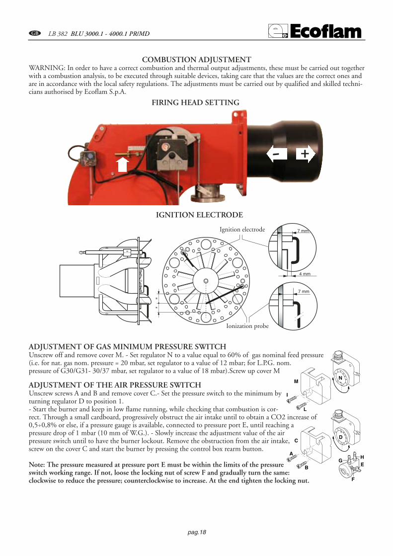
COMBUSTION ADJUSTMENT WARNING: In order to have a correct combustion and thermal output adjustments, these must be carried out togetherwith a combustion analysis, to be executed through suitable devices, taking care that the values are the correct ones andare in accordance with the local safety regulations. The adjustments must be carried out by qualified and skilled techni-cians authorised by Ecoflam S.p.A.
FIRING HEAD SETTING
IGNITION ELECTRODE
Ionization probe
Ignition electrode
ADJUSTMENT OF GAS MINIMUM PRESSURE SWITCHUnscrew off and remove cover M. - Set regulator N to a value equal to 60% of gas nominal feed pressure(i.e. for nat. gas nom. pressure = 20 mbar, set regulator to a value of 12 mbar; for L.P.G. nom.pressure of G30/G31- 30/37 mbar, set regulator to a value of 18 mbar).Screw up cover M
ADJUSTMENT OF THE AIR PRESSURE SWITCHUnscrew screws A and B and remove cover C.- Set the pressure switch to the minimum byturning regulator D to position 1. - Start the burner and keep in low flame running, while checking that combustion is cor-rect. Through a small cardboard, progressively obstruct the air intake until to obtain a CO2 increase of0,5÷0,8% or else, if a pressure gauge is available, connected to pressure port E, until reaching apressure drop of 1 mbar (10 mm of W.G.). - Slowly increase the adjustment value of the airpressure switch until to have the burner lockout. Remove the obstruction from the air intake,screw on the cover C and start the burner by pressing the control box rearm button.
Note: The pressure measured at pressure port E must be within the limits of the pressureswitch working range. If not, loose the locking nut of screw F and gradually turn the same:clockwise to reduce the pressure; counterclockwise to increase. At the end tighten the locking nut.
2,55
10 15
50
25
35
30
4045
20
0,4
0,6 0,9
3,0
1,5
2,1
1,8
2,42,7
1,2
I
L
MN
A
B
CD
E
F
GH
+-

pag.19
LB 382 BLU 3000.1 - 4000.1 PR/MD B
FIRING HEAD DISASSEMBLY
The ionization current is checked by inserting a microam-meter with an end of scale of 50 µA (d.c.) in series with theionization probe. A faulty position of the electrode can leadto a reduction in the ionization current and cause a safetycut-out of the burner due to a flame detection failure. In thiscase, check the position of the electrode, its electric connec-tion and the earthing of the burner.
24
min. 6 µA
LANDIS LFL1.622Microamperometro fondo scala 50 µA
IONIZATION CURRENT
Microammeter50 µA end of scale
ABCD
A- main switch I / O
B- fuse
C- selector :
0 = operating elements locked in an
intermediate position
= operation on maximum capacity
= operation on minimum capacity
AUTO = automatic operation
D- thermal relaylock-out lamp
E - working lamp
F - reset key
E
F
0
AUTO
0I
DESCRIPTION OF THE CONTROL PANEL OF THE BURNER

pag.20
B LB 382 BLU 3000.1 - 4000.1 PR/MD
RWF 40 MICROPROCESSOR REGULATOR
Display:analog input 1(actual value)
Display: Set point SP1
Decrease value
Programming key
Manual operation
Auxiliary contact
Increase value
EXIT key.
Burner operation
Reduce powerCLOSE/1st Stage
Increase powerOPEN/2nd Stage
Two-stage operation
Description of display and keys on the RWF 40 microprocessor regulatorThe figure shows the normal display indicating
the actual value and the programmed setpoint, and equally important,
gives the meaning of thesingle keys and indicator Leds.
Configuration level
User Level
Normal display
Parameters level
PGM
PGM
PGM
PGM PGMPGM
PGM PGM
PGM PGM
min 2s
min 2s
min 2s
Exit
PROGRAMMING LEVELS

pag.21
LB 382 BLU 3000.1 - 4000.1 PR/MD B
SETTING PARAMETERSWhen the burner is ignited all displays of the regulator light up. The set point display will blink for about 10 seconds. The valuein the upper field of the display (red) indicates the actual value. The value in the lower field of the display (green) indicates the setpoint currently programmed. CHANGING THE SET POINTTo change the set point, proceed as follows: ---- Press the PGMPGM button to access the user level. SP1* will appear in the lower display---- Change the value of set point SP1 using the t and s keys.▼e ▲. ---- After a 2 second delay the value set is stored automatically – Toreturn to normal display press EXITEXIT. ** The value of SP1 depends on the value set previously in configuration level C111.SETTING PID PARAMETERSPID parameters are factory set to standard mean values. The operation of the regulator can be self-adapted to suit the system byactivating the “tunE” function. The regulator will set the PID parameters automatically. To activate the “tunE” function proceedas follows: ---- With the burner in operation, press PGM PGM + ▼. ---- the caption “tunE*” will blink in the display. – When “tunE” stopsblinking, the self-adaptation routine has been completed. ---- Confirm the computed parameters by pressing the ▲ key for 2 seconds. ** The “tunE” function cannot be activated in Manual mode, or when the burner is off. The PID parameters can be corrected manually from the parameters level, working on the proportional band Pb1, the derivati-ve action time dt and the integral action time rt. To change parameters Pb1, dt and rt, proceeds as follows: ---- Press the PGMPGM button to access the parameters level. ---- To move fromone parameter to the next, press PGMPGM . ---- When Pb1 is displayed, the value can be increased or decreased using the s and t keys. ----Confirm the changed parameters by pressing PGMPGM. ---- If confirmation is not given within 2 seconds the value will be stored auto-matically. ---- Press PGMPGM to access the next parameter. ---- When dt is displayed, repeat the procedure described above. ---- Press PGMto access the next parameter. ---- When rt is displayed, repeat the procedure above. ---- To return to normal display press EXITEXIT. DIFFERENTIAL SETTING FOR IGNITION AND SHUTOFFThe regulator allows the selection of an adjustable switching differential that establishes burner ignition and shutoff values.HYS1 indicates the lower ignition limit, below which the regulator switches the burner to maximum power. HYS3 indicatesthe upper shutoff limit, above which the regulator switches the burner off. To set HYS1 and HYS3 proceed as follows: ---- Pressthe PGMPGM key to access the parameters level. ---- To move from one parameter to the next, press PGMPGM . ---- When HYS1 is displayed(burner ignition differential-stage II), increase or decrease the value using the ▼ and ▲ keys. ---- Confirm the changed parameters bypressing PGMPGM. ---- If confirmation is not given within 2 seconds the value will be stored automatically. ---- Press PGMPGM to access thenext parameter. ---- When HYS2 is displayed (burner shutoff differential-stage II), repeat the procedure described above. ---- PressPGMPGM to access the next parameter. ---- When HYS3 is displayed (upper shutoff differential) repeat the procedure described above. ---- To return to normal display press EXITEXIT.
MANUAL/AUTOMATIC MODETo access “MANUAL” mode, press and hold EXITEXIT for at least 5 seconds. Manual mode can only be selected when the burner isin operation. It is deactivated automatically when the burner shuts off. When the LED above the hand symbol is alight, the regu-lator is in manual mode and the position of the servocontrol can be changed using the ▼ and ▲ keys. The LEDS on the front ofthe regulator indicate whether the servocontrol OPEN or CLOSE command is currently active. Pressing the ▼ key the servocon-trol OPENS. Pressing the ▲ key the servocontrol CLOSES. To select automatic mode press and hold EXITEXIT for at least 5 seconds.The LED above the hand symbol goes out and the regulator reverts to automatic.
CLIMATIC COMPENSATIONThe RWF 40 regulator can be set with the set point interlocked to the external probe. To select this operating mode, proceed asfollows: ---- Connect the required probe as in the wiring diagram. ---- Change the regulator settings. When using an external probethe regulator must be set as follows: ---- Press the PGMPGM key to access the configuration level. When the caption C111 (XXXX) isdisplayed, use the ▲ key to access the second figure (XXXX). Use the ▼ key to select the type of probe (XX3X). ---- Confirm thechange of parameters by pressing PGMPGM. If this is not done within 2 seconds, the value is stored automatically ---- Press PGMPGM toaccess the configuration level. When the display reads C112 (XXXX), use the ▲ key to access the second figure (XXXX). Press the▼ key to set the type of probe (XX3X). ---- Confirm the changed parameters by pressing PGMPGM. ---- If confirmation is not givenwithin 2 seconds the value will be stored automatically. ---- To return to normal display press EXITEXIT. To establish the heating curve, proceed as follows: ---- Press PGMPGM to access the parameters level. ---- Press PGMPGM to move from one parameter to the next. ---- When the letter H isdisplayed (heating curve gradient), increase or decrease the value using the ▼ and ▲ keys. ---- Confirm the changed parameters bypressing PGMPGM. ---- If confirmation is not given within 2 seconds the value will be stored automatically. ---- To return to normal display press EXITEXIT.

pag.22
B LB 382 BLU 3000.1 - 4000.1 PR/MD
PROBE CONNECTION DIAGRAMS
SPH
60
80
100
0
20
40
SPL
120
140
160
20 15 10 5 0 -20-15-10-517.5 12.5 7.5 2.5 -2.5 -17.5-12.5-7.5
0.20.40.60.811.21.41.61.822.22.42.62.833.23.43.63.84
External temperature (iC)
Hea
tin
g c
urv
e g
rad
ien
t (H
)
PARAMETERIZATIONB
oile
r te
mp
erat
ure
set
po
int
(iC
)
Cod.S704
Cod. S721Cod.S731
S731/1S731/2S731/3S731/4
Cod.S720/1
Connection for probeQAE2..(passive probe)Water probeConfiguration codeC111 = 9XXX
Connection for probeFT-TP/..(passive probe)(Degusa probe)Configuration codeC111 = 5XXX
Connection for probe QBE620-P..(active probes)Configuration code C111 = GXXXS731 - 0…4 bar / 0…400 kPa QBE620-P4 S731/1 - 0…10 bar / 0…1 MPa QBE620-P10 S731/2 - 0…16 bar / 0…1.6 Mpa QBE620-P16 S731/3 - 0…25 bar / 0…2.5 MPa QBE620-P25 S731/4 - 0…40 bar / 0…4 MPa QBE620-P40
Connection for probeQAC22 (passive probe)Configuration code C111 = XX3XC112 = XX1X
1 2 3 4
RWF 40
B M
G1+ M1
QAE22A
1 2 3 4
RWF 40
B M
B9 M9
QAC2..
1 2 3 4
RWF 40
GL M
G+ M1
OBE620-P..U1
G- U1

pag.23
LB 382 BLU 3000.1 - 4000.1 PR/MD B
- Situation - The number 1999 blinks in the display as the actual value, with the set point value displayed normally.
- Cause - The real value is not being measured. This means that the upper or lowerlimit of the measurement range on analog input 1 (real value) has been exceeded.
- Remedy - Check the electrical connections and the state of the probe. If the probeis faulty, the regulator will not indicate the real value of the physical quantity monitored. This will result in automatic shutdown (failsafe), deactivation of theself-adapt function and inhibition of manual operation. The response of the auxiliary contact will depend on the configuration of parameter C113.
- Situation - The number 1999 blinks in the display as the actual value, with tAshowing in the set point field.
- Cause - The external temperature is not being measured. This means that theupper or lower limit of the measurement range on analog input 3 (real value) hasbeen exceeded.
- Remedy - Check the electrical connections and the state of the probe. If the probeis faulty, the regulator will not indicate the real value.
- Situation - The number 1999 blinks in the display as the actual value, with SP .Eshowing in the set point field.
- Cause - The external set point value is not being measured. This means that theupper or lower limit of the measurement range on analog input 2 (real value) hasbeen exceeded.
- Remedy - Check the electrical connections and the external set point signal. If theprobe is faulty, the regulator will not indicate the real value of the physical quantitymonitored. This will result in automatic shutdown (failsafe), deactivation of the self-adapt function and inhibition of manual operation.
ERROR/FAULT INDICATIONNUMBERS BLINKING IN DISPLAY
Analog input 1 (actual value)Pt1000, 2-wire, Landis & Staefa IEC 751
5FT-TP/… (passive probe)
Ni1000, 2-wire, Landis & Staefa9QAE2 … (passive probe - water probe)
Standard Signal DC 0…10 V QBE620P…(active probe - pressure probe) G
C111 – C112 INPUT CONFIGURATION INDICATIONS
Analog Input 3 (external temperature)No function (probe not active) 0External probe Pt 1000, 2-wire,
1QAC22 (passive probe)
AUXILIARY CONTACT, TYPE OF REGULATOR, SET POINT “SP1”BLOCK C112. Parameter configuration
Set point “SP1”Set point SP1 - data input from keys 0Set point SP1 - interlocked to external probe (configure) 1

pag.24
B LB 382 BLU 3000.1 - 4000.1 PR/MD
A
Insert the RWF 40 regulator through the relative opening in the electrical panel (A). Insert the fixing anchors and screws into the slots, and secure the unit to the panel (B). To open the regulator, squeeze the cover from the ends as shown, and lift out (C).
WHEN REPLACEMENT IS NECESSARY, PROCEED AS SHOWN IN FIGURES A-B-C BELOW
B C
MAINTENANCEANNUAL CHECKThe burner (combustion head, electrodes, etc.) must be checked regularly by an authorized technician, once or twicea year, depending on how much it is used. Before proceeding withe the maintenance check-up on the burner, it isadvisable to check the general condition of the burner and take the following steps: Disconnect the burner (removethe plug). - Close the gas shut-off cock. - Remove the cover from the burner, clean the fan and air intake. - Clean the combustion head and check the position of the electrodes. - Re-install the parts. - Check the seal on the gas connectors. - Check the state of the flue. - Start the burner. - Check the combustion parameters
BEFORE TAKING ANY ACTION, CHECK:- that there is power in the circit and the burner is connected; - that the gas pressure is right and the gas shut-off cock is open; - that the control systems are properly connected. If all these conditions have been satisfied, start the burner by pres-sing the reset button. Check the burner cycle.
IF THE BURNER FAILS TO START:check the switch, the thermostats, the motor and the gas pressure.
IF THE BURNER PROCEEDS WITH PREVENTILATION BUT CUTS OUT AT THE END OF THE CYCLE:check the air pressure and the fan. Check the air pressure switch.
IF THE BURNER PROCEEDS WITH PREVENTILATION BUT DOES NOT LIGHT:check the installation and position of the electrodes. Check the ignition cable. Check the ignition transformer. Check the safety device.
IF THE BURNER LIGHTS BUT CUTS OUT AFTER THE SAFETY INTERVAL: check that the phase and neutral wires are connected correctly. Check the gas solenoid valve. Check the position and connection of the detector electrode. Check the detector electrode. Check the safety device.
IF THE BURNER LIGHTS BUT CUTS OUT AFTER OPERATING FOR A FEW MINUTES:check the pressure regulator and gas filter. Check the gas pressure with a pressure gauge. Check the detector value (atleast 6 µA).

pag.25
LB 382 BLU 3000.1 - 4000.1 PR/MD B
Parameter Display Ecoflam setting Ecoflam setting Ecoflam setting (passive probe) (passive probe) (active probe)
QAE22 FT-TP/1000 QBE620-P...Limit value of limit comparator AL 0 0 0Switching differential for limit comparator HYSt 0 0 0Proportional band Pb.1 8 8 1Derivative time dt 20 20 3Integral action time rt 80 80 15Dead band (neutral zone) db 0.5 0.5 0.5Actuator running time (sec.) tt 25 25 25Switch-on threshold burner / stage II HYS1 -2 -2 -0.2Switch-off level stage II HYS2 0 0 0Upper switch-off threshold HYS3 5 5 0.5Response threshold q 0 0 0Heating curve slope H 2 2 2Parallel displacement P 0 0 0
PARAMETERS
Parameter Display Ecoflam setting(passive probe) (active probe) QBE620-P...
QAE22 FT-TP/1000 -P4 -P10 -P16 -P25 -P40Analog input 1, 2 and 3; setpoint changeover / shift C111 9030 5030 G000 G000 G000 G000 G000Limit comparator; controller type; setpoint 1; locking C112 0010 0010 0010 0010 0010 0010 0010Unit address; decimal place / unit, signal for out-of-range C113 0110 0110 0110 0110 0110 0110 0110Measured value range start analog input 1 SCL 0 0 0 0 0 0 0Measured value range analog input 1 SCH 100 100 4 10 16 25 40Measured value range analog input 2 SCL2 0 0 0 0 0 0 0Measured value range analog input 2 SCH2 0 0 0 0 0 0 0Lower setpoint limit SPL 60 60 0 0 0 0 0Upper setpoint limit SPH 88 88 4 10 16 25 40Actual value correction,analog input 1 OFF1 0 0 0 0 0 0 0Actual value correction,analog input 2 OFF2 0 0 0 0 0 0 0Actual value correction,analog input 3 OFF3 0 0 0 0 0 0 0Filter time constant for digital filter, dF1 1 1 0 0 0 0 0analog input 1
CONFIGURATION

pag.26
C LB 382 BLU 3000.1 - 4000.1 PR/MD
Caracteristiques du bruleur BLU 3000.1 PR/MD BLU 4000.1 PR/MD
Puissance termique max. kW 3000 3900kcal/h 2.586.000 3.362.000
Puissance termique min. kW 630 875kcal/h 543.100 754.300
Pression gaz naturel mbar 40÷300 40÷300Pression LPG mbar 37÷150 37÷150Tension d’alimentation 50 Hz V 230 / 400 230 / 400Moteur kW 5,5 7,5Tours par minute N° 2800 2800Combustible : P.c.i. gaz naturel = 35,9 Mj / Nm3 = 8.570 kcal / Nm3
P.c.i. GPL 22.260 kcal / Nm3
MODELE A B C D D1 E F G H I L M N OBlu 3000.1 941 448 493 330 530 780 290 466 280 315 315 M16 195 250Blu 4000.1 941 448 493 365 565 780 320 466 280 315 315 M16 195 250
D= tête courte D1= tête longue
IM
L
E D - D1
F
CBA
10
23
I
O
GH
N
O
DIMENSIONS D'ENCOMBREMENT
Con
trep
ress
ion
en c
ham
bre
de c
ombu
stio
n
Puissance brûleur
COURBE DE TRAVAILmbar
1500 2000 2500 3000 3500 4000
10
12
14
16
1000
0
2
4
6
8
500
BLU 4000.1
kW
kcal/hx 1000
500 1000 1500 2000 2500 3000 3500
BLU 3000.1

pag.27
LB 382 BLU 3000.1 - 4000.1 PR/MD C
CONNEXION ELECTRIQUETous les brûleurs sont essayés à 400 V, 50 Hz triphasé, avec neutre pour les auxiliaires. Dans le cas où il fût nécessaire alimenter lesbrûleurs à 230 V, 50 Hz triphasé sans neutre, effectuer les modifications nécessaires suivant le schéma electrique du brûleur et con-trôler que le relais thermique soit dans la plage d’absorption du moteur. Vérifier, en outre, le sens de rotation du ventilateur.
CONNEXION AU RESEAU GAZUne fois que le brûleur est connecté à la tuyauterie gaz, il faudra s’assurer que cette dernière soit parfaitement étanche, et que lacheminée ne soit pas obstruée. Une fois ouvert le robinet du gaz, purger très soigneusement la tuyauterie par la prise de pression, etcontrôler, ensuite, la valeur de la pression a l'aide d'un manometre. Brancher le système et régler les thermostats à la températuredésirée. A la fermeture des thermostats, le dispositif de contrôle d’étancheité, effectuera un essais des vannes. Au bout de l'essai, lebrûleur obtiendra le consensus pour le démarrage.
Avant de démarrer le brûleur, s`assurer qu`il soit installé correctement. Vérifier les connexions électriques suivant les plans ainsi quela tuyauterie du système. Avant d`effectuer les connexions électriques~ veiller à ce que le voltage corresponde aux données indiquéessur la plaquette des caractéristiques techniques. Le schéma de la connexion électrique, ainsi que le cycle de démarrage~ sont illustrésséparément. Pour connecter l'appareillage au brûleur, suivre le schéma. Veiller soigneusement à la connexion du neutre et la phase:jamais les inverser. Contrôler la connexion à terre du système. Avec les moteurs triphasés, vérifier le sense giratoire (voir la flèche).Purger l'air et les impuretés de la tuyauterie du gaz, et vérifier que la préssion du gaz soit dans les limites indiquées sur la plaquette.Ce contrôle doit être effectué à l'aide d'un manomètre à gaz connecté à la prise de pression correspondante du brûleur. On démarrele moteur et il commence la preventilation. Le motoréducteur porte le volet de l'air à l`ouverture maximale dans 30 secondes. Lorsque le motoréducteur est complètement ouvert, un signal transmis au dispositif de contrôle démarre un cycle de pre-ventilation de60 secondes env. A la fin de cette dernière, le motoréducteur portera le volet en petite allure, ainsi permettant l`allumage du brûleurà la portée minimale. En même tempst on a l`alimentation du transformateur d'allumage et, après 3 secondes (pre-allumage) onaura l’alimentation des vannes du gaz. A ce point, la vanne à papillon règle la portée du gaz dans la tête de combustion. Deuxsecondes après l'ouverture des vannes, le transformateur est exclus du circuit. En cas de faute d`allumage, le brûleur va en blocagedans deux secondes. Le brûleur est allumé à la puissance minimale (env. 30% de la puissance maximale). Le dispositif modulateur(si prévu) fera ouvrir le servomoteur à la puissance maximale, ou bien il l'arrêtera à la puissance intermédiaire requise par le système.L`ouverture du servomoteur fera ouvrir gaz et air en manière proportionnelle, de façon à avoir une combustion optimale à toutesles portées (30% - 100%). A la fin du fonctionnement le servomoteur se porte en position de fermeture.CONSEILS IMPORTANTS:Tous les organes réglables doivent être fixés par l’installateur après les réglages. Contrôler la combustion dans la che-minée à chaque réglage. Les valeurs de CO2 doivent être d’environ 9,7 (G20) - 9,6 (G25) - 11,7 (l3B) - 11,7 (l3P) et le
DEMARRAGE DU BRULEUR
EX
CE
S D
'AIR
(%)
AIR
FA
CT
OR
PUISSANCE NOMINALE (kW)
1010 20 30 40 50 60
7080
90100 200 300 400
500600
700800
9001000
1,1
1,15
1,21,2 1,2
1,25
1,3
15
20
25
30
2000 30005000
40006000
Gaz Nat.CO2 9,6%
CO <100 ppm
REGLAGE DE LA COMBUSTIONATTENTION : por obtenir un réglage correct de la combustion et du débit thermique, il faut effectuer l'analyse des fuméesen utilisant les instruments appropriés. Le réglage de la combustion et du débit thermique doit être fait en même temps qu’uneanalyse des produits de combustion, en veillant à ce que les valeurs relevées soient correctes, et qu’elles répondent toujours auxnormes de sécurité en vigueur. CETTE OPÉRATION DOIT ETRE FAITE PAR DU LA PERSONNEL QUALIFIÉ ET AUTORISÉ PAR LASOCIÉTÉ ECOFLAM SPA .
GPLCO2 11,7%
CO <50 ppm

pag.28
C LB 382 BLU 3000.1 - 4000.1 PR/MD
Le coffret de sécurité démarre laturbine et commence le pre-balaya-ge de la chambre de combustion.Le pressostat air contrôle la pres-sion de l’air de ventilation afin quele fonctionnement soit correct. A lafin du pre-balayage le transforma-teur d’allumage s’enclenche, parune étincelle entre les éléctrodes, suivi par les les vannes gaz (soupape de sécurité VS et soupape de travail VL). En casde faute d’allumage ou coupure accidentelle du brûleur la sonde à ionisation met le brûleur en sécurité dans le temps desécurité. En cas de coupure du gaz ou de baisses de pression, le pressostat du gaz de pression minimum coupe le fonc-tionnement du brûleur.
COFFRETS DE SECURITE LANDIS & STAEFA MOD. LFL1.622
Rivelazionedi fiamma
Spia di blocco
Valvola gas
Serranda aria
Farfalla gas
Trasformatoredi accensione
Pressostato aria
Motore ventilatore
Pressostato gas
0min
100%
t1 t2
t4
t3
t6t5
Ciclo di funzionamento normaleCiclo di funzionamento
in mancanza di fiamma all'accensionet1 t2
t4
t3
Consensomin./max. potenza
Pressostat gaz
Moteur
Pressostat air
Transformateur
Soupape gaz
Consentimiento mín. / máx. potencia
Cierre del aire
Cierre del gaz
Sonde à ionisation
Lampe de mise ensécurité
Cycle de fonctionnement normal Cycle de fonctionnement par manquede flamme d'allumage
Ref. Descriptiont1 Temps de contrôle du pressostat air
t2 Temps de pre-ventilationt3 Temps de securitét4 Temps de pre-allumaget5 tempo per il consenso di funzionam.
alla minima potenza della valvola dilavoro del combustibile.
t6 tempo per il consenso di funzionam. alla massima potenza della valvola di lavoro del combustibile
Temps
8”
66”2”4”
10”
10”
SERVOMOTEUR LANDIS & STAEFA SQM 50.481A2Enlever le couvercle pour avoir accès aux cames de régulation. La régulation des cames doit être faite à l’aide de la clé endotation. Description:
I - Came de régulation de la position d’ouverture en grande Allure.II - Came de régulation de la position du clapet de l’air à la coupure. III - Came de régulation de la position d’ouverture en min. Allure.IV - Came de régulation de la position d’ouverture en petite Allure.V - Came de régulation libre (non utilisé)VI - Came de régulation libre (non utilisé)VII - Came de régulation libre (non utilisé)VIII - Came de régulation libre (non utilisé)
Came VIII non utilisé
pag.29
LB 382 BLU 3000.1 - 4000.1 PR/MD C
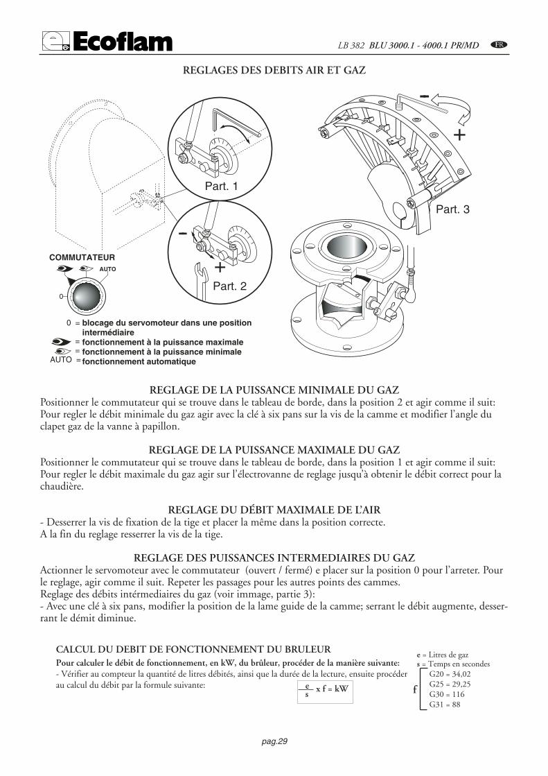
REGLAGE DE LA PUISSANCE MINIMALE DU GAZ Positionner le commutateur qui se trouve dans le tableau de borde, dans la position 2 et agir comme il suit:Pour regler le débit minimale du gaz agir avec la clé à six pans sur la vis de la camme et modifier l’angle duclapet gaz de la vanne à papillon.
REGLAGE DE LA PUISSANCE MAXIMALE DU GAZ Positionner le commutateur qui se trouve dans le tableau de borde, dans la position 1 et agir comme il suit:Pour regler le débit maximale du gaz agir sur l’électrovanne de reglage jusqu’à obtenir le débit correct pour lachaudière.
REGLAGE DU DÉBIT MAXIMALE DE L’AIR- Desserrer la vis de fixation de la tige et placer la même dans la position correcte.A la fin du reglage resserrer la vis de la tige.
REGLAGE DES PUISSANCES INTERMEDIAIRES DU GAZActionner le servomoteur avec le commutateur (ouvert / fermé) e placer sur la position 0 pour l’arreter. Pourle reglage, agir comme il suit. Repeter les passages pour les autres points des cammes.Reglage des débits intérmediaires du gaz (voir immage, partie 3):- Avec une clé à six pans, modifier la position de la lame guide de la camme; serrant le débit augmente, desser-rant le démit diminue.
REGLAGES DES DEBITS AIR ET GAZ
+
--
Part. 1
Part. 2
Part. 3
-
+
-COMMUTATORE
0
AUTO
0 = bloccaggio degli apparati per il funzionamento in una posizione intermadia = funzionamento alla massima potenza = funzionamento alla minima potenza AUTO = funzionamento automatico
blocage du servomoteur dans une positionintermédiaire fonctionnement à la puissance maximale fonctionnement à la puissance minimale fonctionnement automatique
COMMUTATEUR
Pour calculer le débit de fonctionnement, en kW, du brûleur, procéder de la manière suivante:- Vérifier au compteur la quantité de litres débités, ainsi que la durée de la lecture, ensuite procéderau calcul du débit par la formule suivante:
CALCUL DU DEBIT DE FONCTIONNEMENT DU BRULEUR
e x f = kWs
e = Litres de gazs = Temps en secondes
G20 = 34,02G25 = 29,25G30 = 116G31 = 88
f

4 mm
7 mmElettrodo di accensione
Elettrodo di rivelazione
""
7 mm
pag.30
C LB 382 BLU 3000.1 - 4000.1 PR/MD
REGULATION DE LA COMBUSTIONATTENTION: Afin d’obtenir une correcte régulation de la combustion et de la portée thermique, celles-ci doivent êtreeffectuées en même temps à une analyse de la combustion, à se faire par des instruments opportuns, en vérifiant que lesdonnées sont correctes et correspondantes aux normes de sécurité locales. Les opérations de régulations doivent êtreeffectuées par des techniciens experts et qualifiés, autorisés par Ecoflam S.p.A.
REGULATION DE LA TETE DE COMBUSTION
POSITION DES ELECTRODES
Sonde de ionisation
Electrode d’allumage
REGLAGE DU PRESSOSTAT GAZ DE MINIMUMDévisser les vis I et L et enlever le couvercle M. - Positionner le régulateur N à un valeur équivalentau 60% de la pression nominale d’alimentation du gaz(par ex.: pour gaz nat. avec pression nom.de 20 mbar, positionner le régulateur à une valeur de 12 mbar; pour G.L.P. avec pressionnom. G30/G31 30/37 mbar, positionner le régulateur à 18 mbar). - Remonter le couvercleM et visser les vis I et L.
REGULATION DU PRESSOSTAT AIRDévisser les vis A et B et enlever le couvercle. Réguler le pressostat air au minimum en tournant le régula-teur D en position 1. Démarrer le brûleur en 1e allure et effectuer une analyse de la combustion.A l’aide d’un petit carton obstruer progressivement le conduit d’aspiration de l’air jusqu’àobtenir une augmentation de CO2 de 0,5÷0,8% ou bien, si l’on dispose d’un manomètre con-necté à la prise de pression E, jusqu’à obtenir une chute de pression de 1 mbar (10 mmC.E.). Augmenter progressivement la valeur de la régulation du pressostat jusqu’à obtenirl’arrêt en sécurité du brûleur. Enlever l’obstruction du conduit, visser le couvercle C etdémarrer le brûleur en appuyant sur la touche de réarmement du coffret de sécurité.Note: La pression mesurée à la prise de pression E doit être comprise dans les limites de la plage de travaildu pressostat. Sinon, dévisser l’écrou de blocage de la vis F et la tourner graduellement: à droite pour réduire la pres-sion; à gauche pour l’augmenter. Enfin serrer l’écrou de blocage.
2,55
10 15
50
25
35
30
4045
20
0,4
0,6 0,9
3,0
1,5
2,1
1,8
2,42,7
1,2
I
L
MN
A
B
CD
E
F
GH
+-

pag.31
LB 382 BLU 3000.1 - 4000.1 PR/MD C
24
min. 6 µA
LANDIS LFL1.622Microamperometro fondo scala 50 µA
CONTROLE SYSTEME DETECTION DE FLAMME
Avec le brûleur énteint, brancher un microampe-romètre à courante continue scale 50 µA. Si posi-tionè erronéament, l’électrode peut provoquerl’arrêt du brûleur. Il faut bien contrôler la positionde l’electrode, les branchements eletriques et la miseà la masse du brûleur. La valeur doit être stable etjamais inférieure à 20 µA.
ENLEVEMENT DE LA TETE DE COMBUSTION
ABCD
A- Interrupteur
B- fusible
C- commutateur
0 = blocage des dispositifs pour le fonctionnement d'une position intermédiaire
= fonctionnement à la puissance maximale
= fonctionnement à la puissance minimale
AUTO = fonctionnement automatique
D - lampe de securité
E - lampe de fonctionnement
F - touche de réarmement
E
F
0
AUTO
0I
DESCRIPTION DU TABLEAU DE COMMANDE DES BRULEURS

pag.32
C LB 382 BLU 3000.1 - 4000.1 PR/MD
REGULATEUR COMPACT UNIVERSEL RWF40
Affichage à cristaux liquides:
Entrée analogique1 (valeur réelle)
Affichage à cristaux liquides:
consigne SP1
Reduction de la valeur
Touche de programmation (PGM)
Signal commande manuelle « MARCHE/ARRET »
Contact auxiliaire
Augmentation de la valeur
Touche sortie (EXIT)
Fonctionnement du brûleur
Signal de commande« FERMETURE »
du servomoteur
Signal de commande« OUVERTURE »
du servomoteur
Signal du fonctionnement du brûleur à 2 allures
Déscription de l’affichage à cristaux liquides (display) et des touches du regulateur RWF40
Niveau configuration
Niveau utilisateur
Affichage à cristaux liquides ordinaire
Niveau paramètres
PGM
PGM
PGM
PGM PGMPGM
PGM PGM
PGM PGM
min 2s
min 2s
min 2s
Exit
NIVEAUX DE PROGRAMMATION

pag.33
LB 382 BLU 3000.1 - 4000.1 PR/MD C
INTRODUCTION DES PARAMETRES
A l’allumage du brûleur tous les LED sur la façade sont allumés. L’ affichage à cristaux liquides (display) du consigne clignoterapour environ 10sec. L’affichage à cristaux liquides supérieur (rouge) indique la valeur mesurée et pendant le reglage, il indique lesparamètres entrés; celui inférieur (vert) indique la consigne.
REGLAGE DE LA CONSIGNE Pour regler la consigne il faut agir comme il suit.: ---- Avec la touche PGMPGM on joint le niveau utilisateur, sur l’ affichage à cristauxliquides est visualisée SP1*. - Modifier la valeur de la consigne SP1 avec les touches �et �. ---- Après 2sec. La valeur consignée estautomatiquement mise en memoire. ---- Pour retourner dans le premier affichage touche EXITEXIT.** La valeur SP1 dépend de la valeur consignée dans le niveau de configuration C111.
CONSIGNE DES PARAMETRES PIDLes paramètres PID sont déjà reglés pendant l’installation sur le brûleur avec valeurs standards. Il est possible d’adapter le fonction-nement du régulateur selon l’installation activant “auto-adaptation” “tunE” clignotant. Le regulateur calcule lui même les paramè-tres de regulation PID. Pour activer la fonction “tunE” il faut agir comme il suit: ---- démarrer “auto-adaptation” avec la touchePGM PGM + �avec le brûleur en fonction. ---- Sur l’affichage apparaîtra “tunE*” clignotant. ---- Quan elle ne clignotera pas “auto-adapta-tion”sera terminée. ---- Confirmer les paramètres enforçant la touche �pour 2 sec.. ** “tunE” ne peut pas etre actué quand le regulateur est en fonctionnement manuelle ou avec le brûleur arreté.Les paramètres PID peuvent être modifiés manuellement au niveau paramètres agissant sur la bande proportionnelle Pb1,temps de dosage de dérivation dt et temps de dosage d’ intégration rt. Pour modifier les paramètres Pb1, dt, rt il faut agir comme il suit : ---- On accede au niveau paramètres par la touche PGMPGM . ---- Onaccede au paramètres suivant toujours par la touche PGMPGM. ---- Quand l’affichage indique Pb1. ---- On augmente ou diminue lavaleur par les touches �et �. ---- Confirmer les paramètres par la touche PGMPGM, la valeur est quand même memorisée dans 2sec. ----On accede au paramètre suivant par la touche PGMPGM . ---- Quand l’affichage indique dt l’on peut repeter les instructions précédentes---- On accede au paramètre suivant toujour par la touche PGMPGM ---- Quand l’affichage indique rt l’on peut repeter les instructionsprécédentes ---- On retourne au premier affichage par la touche EXITEXIT.
REGLAGE DU DIFFERENTIELLe régulateur permet de afficher une valeur différentielle de commutation reglable qui permet la marche et l’arrêt du brûleur.Avec HYS1 on indique la limite inférieure sous laquelle le brûleur se met en marche.Avec HYS3 on indique la limite supérieure sur laquelle le brûleur s’arrête.Pour afficher des valeurs de consigne à HYS1 et HYS3 il faut agir comme il suit: ---- On accede au niveau paramètres par la touchePGMPGM . ---- On accede au paramètres suivant toujours par la touche PGMPGM. ---- Quand l’affichage indique HYS1 (différentiel d’allu-mage) ---- On augmente ou diminue la valeur par les touches �et �. ---- Confirmer les paramètres par la touche PGMPGM, la valeur estquand même memorisée dans 2sec. ---- On accede au paramètre suivant par la touche PGMPGM . ---- Quand l’affichage indique HYS2(différentiel d’arrêt) l’on peut repeter les instructions précédentes ---- On accede au paramètre suivant toujour par la touche PGMPGM.---- Quand l’affichage indique HYS3 (différentiel supérieur d’arrêt) l’on peut repeter les instructions précédentes---- On retourne au premier affichage par la touche EXITEXIT.
FONCTIONNEMENT MANUEL/AUTOMATIQUE On accede au fonctionnement « MANUEL » appuyant la touche EXIT EXIT pour 5sec. Le fonctionnement manuel peut être mis enroute seulement quand le brûleur est en marche, il est automatiquement mis hors de service quand le brûleur s’arrête. Quand lerégulateur est en fonctionnement manuel (LED sur le symbole de la main allumé) l’on peut modifier la position du servomoteurpar les touches �et �. Les LED allumés sur la façade du régulateur indiquent si la commande OUVRE ou FERME du servomo-teur est activé. Appuyant la touche � le servomoteur ouvre; appuyant la touche � le servomoteur ferme. Appuyant la toucheEXITEXIT pour 5sec. On passe au fonctionnement automatique ; le LED sur le symbole de la main s’éteint et le régulateur est en fonc-tionnement automatique.
COMPENSATION CLIMATIQUELa compensation climatique est utilisée seulement dans le cas où une sonde extérieure soit branchée. Si le brûleur est utilisé avecune chaudière à vapeur, la compensation climatique n’est pas utilisée.

pag.34
C LB 382 BLU 3000.1 - 4000.1 PR/MD
SPH
60
80
100
0
20
40
SPL
120
140
160
20 15 10 5 0 -20-15-10-517.5 12.5 7.5 2.5 -2.5 -17.5-12.5-7.5
0.20.40.60.811.21.41.61.822.22.42.62.833.23.43.63.84
température éxtérieure (°C)
Co
nsi
gn
e te
mp
érat
ure
ch
aud
ière
(°C
)
Pen
te c
ou
rbe
de
chau
ffag
e (
H )
PARAMETRISATION
Cod.S704
Cod. S721Cod.S731
S731/1S731/2S731/3S731/4
Cod.S720/1
Branchement sondeQAE2..(sonde passive)Sonde eau Code C111 = 9XXX
Branchement sondeFT-TP/..(sonde passive)Code C111 = 5XXX
Branchement sonde QBE620-P..(sonde active)Code C111 = GXXXS731 - 0…4 bar / 0…400 kPa QBE620-P4 S731/1 - 0…10 bar / 0…1 MPa QBE620-P10 S731/2 - 0…16 bar / 0…1.6 Mpa QBE620-P16 S731/3 - 0…25 bar / 0…2.5 MPa QBE620-P25 S731/4 - 0…40 bar / 0…4 MPa QBE620-P40
Branchement sondeQAC22 (sonde passive)Code C111 = XX3X
C112 = XX1X1 2 3 4
RWF 40
B M
G1+ M1
QAE22A
1 2 3 4
RWF 40
B M
B9 M9
QAC2..
1 2 3 4
RWF 40
GL M
G+ M1
OBE620-P..U1
G- U1
Schéma de branchement avec les sondes

pag.35
LB 382 BLU 3000.1 - 4000.1 PR/MD C
- Situation - L’affichage de la valeur réelle indique 1999 clignotant et sur l’affichage de consigne il y a la valeur consignée.
- Cause - La valeur réelle n’est pas mesurée. Ça signifie que la valeur du champs de travail de l’entrée analogique 1 (valeur réelle) a étée dépassée (plus haut ou plus bas).
- Remède - Vérifier les branchements éléctriques et l’integrité de la sonde. Dans le cas où la sonde soit détériorée, le régulateur ne revèle pas la valeur réelle à contrôler et il éteint le brûleur automatiquement pour securité; il désactive l’auto-adaptation ainsi que le fonctionnement manuel.Le contact auxiliaire repond sélon la configuration du paramètre C113
- Situation - L’affichage de la valeur réelle indique 1999 clignotant et l’affichage de consigne indique tA.
- Cause - La température éxtérieure n’est pas mesurée. Ça signifie que la valeur du champs de travail de l’entrée analogique 3 (valeur réelle) a étée dépassée (plus haut ou plus bas).
- Remède - Vérifier les branchements éléctriques et l’integrité de la sonde. Dans le cas où la sonde soit détériorée, le régulateur ne revèle pas la valeur réelle.
- Situation - L’affichage de la valeur réelle indique 1999 clignotant et l’affichage de consigne indique SP .E.
- Cause - La valeur de la consigne n’est pas mesurée. Ça signifie que la valeur du champs de travail de l’entrée analogique 2 (valeur réelle) a étée dépassée (plus haut ou plus bas).
- Remède - Vérifier les branchements éléctriques et le signal de la consigne extérieure. Dans le cas où la sonde soit détériorée, le régulateur ne revèle pas la valeur réelle à contrôler et il éteint le brûleur automatiquement pour securité; il désactive l’auto-adaptation ainsi que le fonctionnement manuel.
SIGNALATION DES FAUTES ET D’ ANOMALIES CLIGNOTEMENT DU NUMERO SUR L’AFFICHAGE A’ CRISTAUX LIQUIDES (DISPLAY)
Entrée analogique 1 (valeur réelle)Pt1000, 2 fils, Landis & Staefa IEC 751
5FT-TP/...(sonde passive )Ni1000, 2 fils, Landis & Staefa
9QAE2... (sonde passive sonde eau )Signal standard DC 0...10 V QBE620-P...(sonde active, sonde de préssion) G
INDICATION DE CONFIGURATION ENTREES C111-C112
Entrée analogique 3 (température éxtérieure)Aucune fonction (sonde non active) 0Sonde éxtérieure Pt 1000, 2 fils,
1QAC22 (sonde passive)
CONTACT AUXILIAIRE, TYPE DE REGULATEUR CONSIGNE “SP1” BLOCAGE C112. Configuration des paramètres
Consigne “SP1”Consigne SP1 consigne des données avec touches 0Consigne SP1 configuration avec sonde éxtérieure 1

pag.36
C LB 382 BLU 3000.1 - 4000.1 PR/MD
MAINTENANCECONTROLE ANNUELLe contrôle périodique du brûleur (tête de combustion, électrodes, etc.) doit être effectué, par un technicien autorisé, une ou deuxfois par an, suivant l’utilisation. Avant de procéder au contrôle pour la maintenance du brûleur, il est souhaitable de contrôler l’étatgénéral du brûleur et d’effectuer les opérations suivantes: - Débrancher le brûleur (enlever la prise). - Fermer le robinet d’arrivée du gaz. - Enlever le couvercle du brûleur, nettoyer le ventila-teur et l’aspiration de l’air. - Nettoyer la tête de combustion et contrôler la position des électrodes. - Remonter les pièces. - Contrôler l’étanchéité des raccords gaz. - Contrôler la cheminée. - Faire redémarrer le brûleur. - Contrôler les paramètres de lacombustion (CO2 = 9,7 (G20); 9,6 (G25); 11,7 (G30); 11,7 (G31), (C0 = inférieur à 75 p.p.m.).AVANT CHAQUE INTERVENTION CONTROLER :- Qu’il y ait du courant électrique dans l’installation et que le brûleur soit branché. - Que la pression du gaz soit correcte et que lerobinet d’arrivée du gaz soit ouvert. - Que les systèmes de contrôle soient branchés correctement. - Si toutes ces conditions sontaccomplies, faire démarrer le brûleur en appuyant sur le bouton de déblocage. Contrôle le cycle du brûleur.LE BRULEUR NE DEMARRE PAS :- Contrôler l’interrupteur, les thermostats, le moteur, la pression du gaz.LE BRULEUR EFFECTUE LE PREBALAYAGE ET SE BLOQUE A LA FIN DU CYCLE:- Contrôler la pression de l’air et le ventilateur. - Contrôler le pressostat de l’air.LE BRULEUR EFFECTUE LA PREBALAYAGE ET NE S’ALLUME PAS:- Contrôler le montage et la position des électrodes. - Contrôler le câble d’allumage. - Contrôler le transformateur d’allumage. - Contrôler le coffret de sécurité.LE BRULEUR S’ALLUME ET SE BLOQUE APRES LE TEMPS DE SECURITE- Contrôler que la phase et le neutre soient branchés correctement. - Contrôler l’électrovanne du gaz. - Contrôler la position del’électrode de détection et son branchement. - Contrôler l’électrode de détection. - Contrôler le dispositif de sécurité.LE BRULEUR S’ALLUME ET SE BLOQUE APRES QUELQUES MINUTES DE FONCTIONNEMENT:- Contrôler le régulateur de pression et le filtre du gaz. - Contrôler la pression du gaz avec un manomètre. - Contrôler la valeur dedétection (6 µA min.).
A
Les déscriptions A,B,C indiquent comme l’on doit démonter et remonter le régulateurRWF40.C – Pour enlever le régulateur, exercer une pression sur le couvercle et enléver le même.A – Introduire le régulateur RWF40 dans l’ouverture B – Introduire les vis tamponées dans les fentes et les fixer sur le panneau.
SUBSTITUTION DU REGULATEUR
B C

pag.37
LB 382 BLU 3000.1 - 4000.1 PR/MD C
Parametro Display Valore impostato Valore impostato Valore impostato(sonda passiva) (sonda passiva) (sonda attiva)
QAE22 FT-TP/1000 QBE620-P...Valore limite del contatto ausiliario AL 0 0 0Differenziale di commutazione del contatto ausiliario HYSt 0 0 0Banda proporzionale Pb.1 8 8 1Tempo dell’azione derivata dt 20 20 3Tempo dell’azione integrale rt 80 80 15Banda morta db 0.5 0.5 0.5Tempo di corsa del servocomando (sec.) tt 25 25 25Differenziale di accensione bruciatore/II stadio HYS1 -2 -2 -0.2Differenziale di spegnimento del II stadio HYS2 0 0 0Differenziale superiore di spegnimento HYS3 5 5 0.5Soglia di reazione q 0 0 0Pendenza della curva di riscaldamento H 2 2 2Spostamento parallelo P 0 0 0
PARAMETRES
Parametro Display Valore impostato(sonda passiva) (sonda attiva) QBE620-P...
QAE22 FT-TP/1000 -P4 -P10 -P16 -P25 -P40Ingresso analogico1,2 e 3; commutazione/modifica del setpoint C111 9030 5030 G000 G000 G000 G000 G000Contatto ausiliario; tipo di regolatore;setpoint 1;blocco C112 0010 0010 0010 0010 0010 0010 0010Indirizzo; cifra decimale/unità di misura;segnale per fuori scala C113 0110 0110 0110 0110 0110 0110 0110Indirizzo scala ingresso analogico 1(valore min. sonda) SCL 0 0 0 0 0 0 0Fine scala ingresso analogico1(valore max. sonda) SCH 100 100 4 10 16 25 40Indirizzo scala ingresso analogico 2(valore min. sonda) SCL2 0 0 0 0 0 0 0Fine scala ingresso analogico2(valore max. sonda) SCH2 0 0 0 0 0 0 0Limite inferiore setpoint SPL 60 60 0 0 0 0 0Limite superiore setpoint SPH 88 88 4 10 16 25 40Correzione del valore reale ingresso analogico 1 OFF1 0 0 0 0 0 0 0Correzione del valore reale ingresso analogico 2 OFF2 0 0 0 0 0 0 0Correzione del valore reale ingresso analogico 3 OFF3 0 0 0 0 0 0 0Costante di tempo del filtro digitale, dF1 1 1 0 0 0 0 0ingresso analogico 1
CONFIGURATION

pag.38
D LB 382 BLU 3000.1 - 4000.1 PR/MD
Caracteristicas tecnicas BLU 3000.1 PR/MD BLU 4000.1 PR/MD
Potencia térmica máx. kW 3000 3900kcal/h 2.586.000 3.362.000
Potencia térmica mín. kW 630 875kcal/h 543.100 754.300
Presión gas natural mbar 40÷300 40÷300Presión LPG mbar 37÷150 37÷150Alimentación eléctrica 50Hz V 230 / 400 230 / 400Motore kW 5,5 7,5Velocidad N° 2800 2800Combustible : P.c.i. gas natural = 35,9 Mj / Nm3 = 8.570 kcal / Nm3
P.c.i. LPG 22.260 kcal / Nm3
MODELO A B C D D1 E F G H I L M N OBlu 3000.1 941 448 493 330 530 780 290 466 280 315 315 M16 195 250Blu 4000.1 941 448 493 365 565 780 320 466 280 315 315 M16 195 250
D= cabeza corta D1= cabeza larga
IM
L
E D - D1
F
CBA
10
23
I
O
GH
N
O
DIMENSIONES TOTALES
Con
trop
resi
ón e
n cá
mar
a de
com
bust
ión
Potencia
CAMPO DE TRABAJOmbar
1500 2000 2500 3000 3500 4000
10
12
14
16
1000
0
2
4
6
8
500
BLU 4000.1
kW
kcal/hx 1000
500 1000 1500 2000 2500 3000 3500
BLU 3000.1
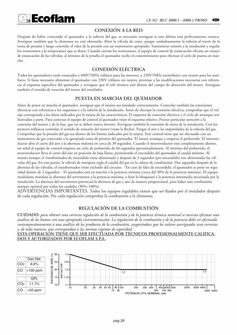
pag.39
LB 382 BLU 3000.1 - 4000.1 PR/MD D
CONEXIÓN ELÉCTRICATodos los quemadores están ensayados a 400V/50Hz trifásico para los motores, y 230V/50Hz monofásico con neutro para los auxi-liares. Si fuese necesario alimentar el quemador con 230V trifásico sin neutro, provéase a las modificaciones necesarias con referen-cia al esquema especifico del quemador y averiguar que el relé térmico esté dentro del campo de absorción del motor. Averiguartambién el sentido de rotación del motor del ventilador.
CONEXIÓN A LA RED Después de haber conectado el quemador a la tubería del gas, es necesario averiguar si esta última está perfectamente estanca.Averiguar también que la chimenea no esté obstruida. Abrir la válvula de corte, purgar cuidadosamente la tubería al través de latoma de presión y luego controlar el valor de la presión con un manometro apropiado. Suministrar tensión a la instalación y regularlos termostatos a la temperatura que se desea. Cuando cierran los termostatos, el equipo de control de estancación efectúa un ensayode estancación de las válvulas; al término de la prueba el quemador recibe el consentimiento para efectuar el ciclo de puesta en mar-cha.
Antes de poner en marcha el quemador, averiguar que el mismo sea instalado correctamente. Controlar también las conexioneseléctricas con referencia a los esquemas y a la tubería de la instalación. Antes de efectuar la conexión eléctrica, comprobar que el vol-taje corresponda a los datos indicados por la tarjeta de las características. El esquema de conexión eléctrica y el ciclo de arranque sonilustrados a parte. Para conectar el equipo de control al quemador véase el esquema relativo. Prestar particular atención a laconexión del neutro y de la fase, que no se deben nunca invertir. Averiguar también la conexión de tierra de la instalación. Con losmotores trifásicos controlar el sentido de rotación del motor (véase la flecha). Purgar el aire y las impuridades de la tubería del gas.Comprobar que la presión del gas sea dentro de los limites indicados por la tarjeta. Este control tiene que ser efectuado con unmanometro de gas conectado a la apropiada toma de presión del quemador. El motor arranque y empieza el prebarrido. El motorre-ductor abre el cierre del aire a la abertura máxima en cerca de 30 segundos. Cuando el motorreductor está completamente abierto,un señal al equipo de control empieza un ciclo de prebarrido de 66 segundos aproximadamente. Al término del prebarrido, elmotorreductor lleva el cierre del aire en posición de baja llama, permitiendo el encendido del quemador al caudal mínimo. Almismo tiempo, el transformador de encendido viene alimentado y después de 3 segundos (pre-encendido) son alimentadas las vál-vulas del gas. En este punto, la válvula de mariposa regla el caudal del gas en la cabeza de combustión. Dos segundos después de laabertura de las válvulas, el transformador viene excluido del circuito. - En caso de falta de encendido, el quemador se pone en segu-ridad dentro de 2 segundos. - El quemador está en marcha a la potencia mínima (cerca del 30% de la potencia máxima). El equipomodulante mandara la abertura del servomotor a la potencia máxima, o bien lo bloqueará a la potencia intermedia necesitada por lainstalación. La abertura del servomotor provocará la abertura de gas y aire de manera proporcional, para haber una combustiónsiempre optimal por todos los caudales (30%÷100%).ADVERTENCIAS IMPORTANTES. Todos los equipos regulables tienen que ser fijados por el instalador despuésde cada regulación. Por cada regulación comprobar la combustión a la chimenea. 9,6 (11,7 inferior 75 ppm.
PUESTA EN MARCHA DEL QUEMADOR
EX
CE
SS
O D
E A
IRE
(%)
AIR
FA
CT
OR
POTENCIA ÚTIL NOMINAL (kW)
1010 20 30 40 50 60
7080
90100 200 300 400
500600
700800
9001000
1,1
1,15
1,21,2 1,2
1,25
1,3
15
20
25
30
2000 30005000
40006000
Gas Nat.CO2 9,6%
CO <100 ppm
REGULACIÓN DE LA COMBUSTIÓNCUIDADO: para obtener una correcta regulación de la combustión y de la potencia térmica nominal se necesita efectuar unaanálisis de los humos con una apropiada instrumentación. La regulación de la combustión y de la potencia debe ser efectuadacontemporáneamente a una análisis de los productos de la combustión, asegurándose que los valores averiguados sean correctosy, de toda manera, que correspondan a las normas vigentes de seguridad. ESTA OPERACION TIENE QUE SER EFECTUADA POR TÉCNICOS PROFESIONALMENTE CALIFICA-DOS Y AUTORIZADOS POR ECOFLAM S.P.A.
GPLCO2 11,7%
CO <50 ppm

pag.40
D LB 382 BLU 3000.1 - 4000.1 PR/MD
El equipo de control de llama poneen marcha el quemador para efec-tuar el prebarrido de la cámara decombustión, controlando la presióndel aire de ventilación por mediodel presóstato del aire. Al términodel prebarrido se activa el transfor-mador de encendido, generandouna chispa entre los electrodos y al mismo tiempo se abren las válvulas del gas (válvula de seguridad VS y válvula de tra-bajo VL). La seguridad total, en caso de falta de encendido o de apagado accidental está confiada à una sonda de detec-ción que activa la puesta en seguridad de la instalación dentro del tiempo de seguridad. En caso de falta de gas o de unanotable bajada de presión, el presóstato gas de mínima provee a cortar el funcionamiento del quemador.
CICLOS DE FUNCIONAMIENTO DEL EQUIPO LANDIS & STAEFA MOD. LFL1.622
Rivelazionedi fiamma
Spia di blocco
Valvola gas
Serranda aria
Farfalla gas
Trasformatoredi accensione
Pressostato aria
Motore ventilatore
Pressostato gas
0min
100%
t1 t2
t4
t3
t6t5
Ciclo di funzionamento normaleCiclo di funzionamento
in mancanza di fiamma all'accensionet1 t2
t4
t3
Consensomin./max. potenza
Presóstato gas
Motor del ventilador
Presóstato aire
Transformadorde encendido
Válvula gas
Consentimiento mín. / máx. potencia
Cierre del aire
Detección de llama
Indicador de bloqueo
Indicador de bloqueo
Ciclo de funcionamiento normalCiclo de funcionamiento con falta
de llama al arranqueRef. Descripciónt1 Tiempo de espera de la confirmación
presión del aire
t2 Tiempo de prebarridot3 Tiempo de seguridadt4 Tiempo de pre-encendidot5 Tiempo para el consentimiento de
funcionamiento de la válvula de trabajodel combustible a la potencia mínima.
t6 Tiempo para el consentimiento de funcionamiento de la válvula de trabajo del combustible a la potencia mínima.
Duración
8”
66”2”4”
10”
10”
SERVOMOTOR DEL CIERRE DEL AIRE LANDIS & STAEFA SQM 50.481A2 Remover la tapa para acceder a las levas de regulación.La regulación de las levas tiene que ser efectuada con su apropiada llave de suministro. Descripción:
I - Leva de regulación abertura del cierre del aire en la potencia máx.II - Leva de regulación de la posición del cierre al apagado (cierre)III - Leva de regulación abertura del cierre del aire en la potencia min.IV - Leva de regulación abertura del cierre del aire en la Baja Llama.V - No utilizarVI - No utilizarVII - No utilizarVIII - No utilizar
Leva VIII no utilizar

pag.41
LB 382 BLU 3000.1 - 4000.1 PR/MD D
REGULACIÓN DEL CAUDAL DE AIRE Y GAS
+
--
Part. 1
Part. 2
Part. 3
-
+
-COMMUTATORE
0
AUTO
0 = bloccaggio degli apparati per il funzionamento in una posizione intermadia = funzionamento alla massima potenza = funzionamento alla minima potenza AUTO = funzionamento automatico
REGULACIÓN DE LA POTENCIA MÍNIMA DEL GASPosicionar el conmutador colocado sobre el cuadro de mandos a la posición 2 y proceder como sigue:Para regular el caudal mínimo de gas proceder con la llave hexagonal sobre el tornillo de la biela y modificar el ángulode la clapeta de gas de la válvula de mariposa
REGULACIÓN DE LA POTENCIA MÁXIMA DE GASPosicionar el conmutador colocado sobre el cuadro de mandos a la posición 1 y proceder como sigue:Para regular el caudal máximo de gas proceder sobre la electroválvula de regulación hasta obtener el valor correcto parala caldera.
REGULACIÓN DEL CAUDAL MÁXIMO DE AIREAflojar el tornillo de fijación del asta y posicionar la misma en la posición correcta.Al final de la regulación volver a cerrar el tornillo del asta.
REGULACIÓN DEL CAUDAL INTERMEDIO DE GASAccionar el servomotor con el conmutador (abierto/cerrado) y ponerlo en la posición 0 para bloquear la carrera. Para la regulación proceder como sigue: Repetir los mismos pasos para los otros puntos del excéntrico.Regulación de los caudales intermedios de gas (véase la ilustración parte 3):Con una llave hexagonal modificar la posición de la hoja de guia del excéntrico, atornillando se aumenta el caudal,destornillando se disminuye
Bloqueo de los equipos parafuncionamiento en una posición intermediaFuncionamiento a la potencia máximaFuncionamiento a la potencia mínimaFuncionamiento automático
CONMUTADOR
Para calcular la potencia de funcionamiento, en kW, del quemador, proceder de lamanera siguiente : Comprobar al contador la cantidad de litros suministrados y la dura-ción, en segundos, de la lectura, luego proceder al calculo de la potencia con la formulasiguiente:vd
CALCULO DE LA POTENCIA DE FUNCIONAMIENTO DEL QUEMADOR
e x f = kWs
G20 = 34,02G25 = 29,25G30 = 116G31 = 88
f
e = Litros de gass = Tiempo en segundos

4 mm
7 mmElettrodo di accensione
Elettrodo di rivelazione
""
7 mm
pag.42
D LB 382 BLU 3000.1 - 4000.1 PR/MD
REGULACIÓN DE LA COMBUSTIÓNCUIDADO: para obtener una correcta regulación de la combustión y del caudal térmico, estos tienen que ser hechosconjuntamente a una análisis de la combustión, a efectuarse por medio de instrumentos apropiados, comprobando quelos datos sean correctos y se conformen a las normas de seguridad locales. Las operaciones de regulación tienen que serefectuadas por técnicos expertos y calificados, autorizados por Ecoflam S.p.A.
REGULACION CABEZA DE COMBUSTION
POSICIÓN DE LOS ELECTRODOS
Electrodo de encendido
Sonda de ionización
REGLAJE DEL PRESOSTATO GAS DE MÍNIMA PRESIÓNDestornillar y quitar la tapa M. - Posicionar el regulador N a un valor igual al 60% de la presiónnominal de alimentación el gas (ej. para gas nat. con pres. nom. de alim. de 20 mbar, regula-dor regulado al valor de 12 mbar; para G.P.L. con pres. nom. de alim. G30-G31 30/37mbar, regulador regulado al valor 18). - Remontar la tapa M y fijarla
REGULACIÓN DEL PRESOSTATO DEL AIREDestornillar los tornillos A y B y quitar la tapa. Regular el presostato del aire al mínimorodando el regulador en la posición 1. Arrancar el quemador en baja llama y comprobar que lacombustión sea correcta. Por medio de una tarjeta, obstruir progresivamente el conducto deaspiración del aire, hasta obtener un aumento de CO2 del 0,5÷0,8% o bien, al disponer deun manometro conectado a la toma de presión E, hasta obtener una caída de presión de 1mbar (10 mm C.A.). Aumentar progresivamente el valor de la regulación del presostatohasta que el quemador se para en seguridad. Quitar la obstrucción y atornillar la tapa,luego arrancar el quemador presionando el botón de rearme del equipo de control.Nota: La presión medida a la toma del aire E debe estar dentro de los limites del campo de trabajo del pre-sostato. En caso contrario, destornillar la tuerca de bloqueo del tornillo F y rodarlo progresivamente: a la dere-cha para disminuir la presión; a la izquierda para aumentarla. Al final atornillar la tuerca de bloqueo.
2,55
10 15
50
25
35
30
4045
20
0,4
0,6 0,9
3,0
1,5
2,1
1,8
2,42,7
1,2
I
L
MN
A
B
CD
E
F
GH
+-

pag.43
LB 382 BLU 3000.1 - 4000.1 PR/MD D
24
min. 6 µA
LANDIS LFL1.622Microamperometro fondo scala 50 µA
CORRIENTE DE IONIZACIÓN
El controle de la corriente de ionización se efectúaconectando un microamperímetro de escala de 50µA (corriente continua)en serie al electrodo de ioni-zación. Una colocación errada del electrodo puedecomportar una reducción de la corriente de ioniza-ción y causar un bloqueo en seguridad del quema-dor, debido a una falta de detección de la llama. Eneste caso, comprobar la correcta colocación del elec-trodo, la conexión eléctrica y la toma a tierra delquemador. Normalmente, el valor de la a corrientede ionización es >20 µA.
DESMONTAJE DELLA CABEZA DE COMBUSTION
Microamperómetroescala de 50 µA.
ABCD
A- Interruptor: en marcha / apagado
B- fusible
C- Conmutador:
0 = bloqueo de los equipos para funcionamiento en posición intermedia
= funcionamiento a la potencia máxima
= funcionamiento a la potencia mínima
AUTO = automatic operation
D- Indicador de bloqueo relé termico
E - Indicador de funcionamiento
F - pulsador de desbloqueo
E
F
0
AUTO
0I
DESCRIPCIÓN DEL CUADRO DE MANDOS DEL QUEMADOR

pag.44
D LB 382 BLU 3000.1 - 4000.1 PR/MD
Nivel de configuración
Nivel de usuario
Display básico
Nivel parámetros
PGM
PGM
PGM
PGM PGMPGM
PGM PGM
PGM PGM
min 2s
min 2s
min 2s
Salir
NIVEL DE PROGRAMACION
Display valor real
Display consigna SP1
Disminuye valor
Botón PMG
Control manual
Comparador de límite
Incrementa valor
Botón SALIR
Liberación del quemador
Unidad de controlCIERRA / 1ª etapa
Unidad de controlABRE/ 2ª etapa
Funcionamento bistadio
Significado del display y de los botones del controlador microprocesador RWF 40La pantalla del RWF40... muestra los valores y símbolos de una
situación tras ser conectado. Esta situación es la del display básico. El valor real y la consigna actual activa aparecen aquí. El funcionamiento manual, autoajuste, los niveles de usuario,parámetros y configuración se activan desde aquí.
CONTROLADOR MICROPROCESADOR RWF 40

pag.45
LB 382 BLU 3000.1 - 4000.1 PR/MD D
MANEJO DE LOS PARAMETROSEn el encendido del quemador todos los displays están iluminados, el display de la consigna parpadea durante unos 10segundostras su conexión. El valor real aparece en el display de valor real (rojo). La consigna aparece en el display de consigna (verde).CAMBIO CONSIGNA Para modificar las consignas hay que proceder como sigue: ---- Con el tras PGMPGM se visualizan el nivel de usuario, aparece en eldisplay básico SP1*. - Modificar la consigna «SP1» con el pulsando �y �. ---- Transcurridos 2 segundos, el valor se consignaautomáticamente. ---- Volver al display básico con EXITEXIT.** El valor SP1 depende da los valor colocados en el nivel de configuración C111MANEJO DE LOS PARAMETROS PIDLos parámetros PID han sido colocados ya en fábrica sobre valores medios standard. Es’ posible adaptar el funcionamiento delregulador. En función de la instalación, activando la función Autoajuste “tunE”. El regulador Se encargará de colocar los paráme-tros PID en automático. Para activar la función“tunE” hay que proceder como sigue: ---- Con el quemador en función arranque delautoajuste con PGM PGM + �. ---- El texto «tunE» parpadea en el display ---- Cuando «tunE » deja de parpadear, el autoajuste se para. ----Aceptar los parámetros que se han seleccionado pulsando (pulsar el botón durante al menos 2 sec.) �. ** No es posible arrancar «tunE » en funcionamiento manual o con función termostato.se pueden corregir manualmente por el nivel parámetros actuando en la banda proporcional Pb1, derivada de tiempo dt enintegrada de tiempo rt. Par modificar los parámetros Pb1, dt, rt, hay que actuar como sigue: ---- Con el tras PGMPGM se puede pasar al nevel parámetros. ----puede pasarse al siguiente parámetro pulsando PGMPGM. ---- Cuando en el dislay aparezca el escrito Pb1. ---- Incrementar o disminuirel valor pulsando �y �. ---- Aceptar los parámetros pulsando PGMPGM, transcurridos 2 segundos, el valor consignado es automática-mente adoptado. ---- Con el tras PGMPGM se puede pasar al siguiente parámetro ---- Cuando en el display aparezca el escrito dt se repitenlas instrucciones. ---- Con el tras PGMPGM se puede pasar al siguiente parámetro ---- Cuando en el display aparezca el escrito rt se repitenlas instrucciones. ---- Volver al display básico con EXITEXIT.REGULACIÓN UMBRAL DE ARRANQUE Y DESCONEXION.
El regulador permite colocar un diferencial de conmutación regulable que establece los valores de encendido y apagadodel quemador. Con HYS1 se entiende el l limite inferior de encendido bajo tal hecho el regulador conmuta el quemadora la máxima potencia, con HYS3 se entiende el limite superior de apagado superado tal hecho el regulador apaga el quemador.Para colocar HYS1 e HYS3 hay que actuar como sigue: ---- Con el tras PGMPGM se puede pasar al nevel parámetros. ---- Con el trasPGMPGM se puede pasar al siguiente parámetro ---- Cuando en el display aparecerà el escrito HYS1 (umbral de arranque para 2ª etapadel quemador). ---- Incrementar o disminuir el valor pulsando �y �. ---- Aceptar los parámetros pulsando PGMPGM, transcurridos 2segundos, el valor consignado es automáticamente adoptado. ---- Con el tras PGMPGM se puede pasar al siguiente parámetro. ---- Cuandoen el display aparecerà el escrito HYS2 (umbral de desconexión de la 2ª etapa del quemador) se repiten las instrucciones preceden-tes. ---- Con el tras PGMPGM se puede pasar al siguiente parámetro. ---- Cuando en el display aparecerà el escrito HYS3 (umbral máximode desconexión) se repiten las instrucciones precedentes---- Volver al display básico con EXITEXIT.FUNCIONAMIENTO MANUAL / AUTOMATICOPara acceder a la funcionalidad de funcionamiento MANUAL pulsando EXIT EXIT durante 5 s. El funcionamiento manual sólopuede activarse si el quemador está en función , se desactiva automáticamente cuando el quemador se apaga. Cuando se iluminael LED que está encima del símbolo manual el regulador esta trabajando en manual, cambiar la posición de la unidad de controlcon �y �. Los LEDs de las unidades de control indican si están activadas las funciones «ABIERTO» o «CERRADO». Pulsandoel tras � la unidad de control abre. Pulsando el tras � la unidad de control CIERRA. Volver a modo automático pulsando EXITEXITdurante 5 s. El LED que está encima del símbolo manual se se apaga Ged el regulador se encuentra ahora en automático.
COMPENSACION EXTERNAS El regulador RWF40 se puede configurar con il setpoint que depende de la sonda exterior. Para que eso ocurra hay que colocar elregulador como sigue: ---- Unir la sonda deseada como el esquema eléctrico. ---- Modificar los parámetros del ordenador . Consonda exterior hay que colocar el regulador como sigue: ---- Con el tras PGMPGM se puede pasar al nevel de configuración, cuandoen el display aparezca el texto C111 (XXXX), se utiliza el boton � hasta que se accede a la segunda cifra (XXXX), con il botón �se pone el tipo de sonda(XX3X). ---- Aceptar los parámetros pulsando PGMPGM, transcurridos 2 segundos, el valor consignado esautomáticamente adoptado. ---- Con el tras PGMPGM se puede pasar al nevel de configuración, cuando en el display aparezca el escritoC112 (XXXX), se utiliza el botón � hasta que se accede a la segunda cifra (XXXX),con el botón � se porne el tipo desonda(XX1X). ---- Aceptar los parámetros pulsando PGMPGM, transcurridos 2 segundos, el valor consignado es automáticamente adoptado. ---- Volveral display básico con EXITEXIT.Par manejo de la curva de calor el regulador se coloca como sigue:---- Con el tras PGMPGM se puede pasar al nevel parámetros. ---- Con el tras PGMPGM se puede pasar al siguiente parámetro.---- Cuando en el display aparezca el escrito H (pendiente de la curva de calor). ---- Incrementar o disminuir el valor pulsando �y �.---- Aceptar los parámetros pulsando PGMPGM, transcurridos 2 segundos, el valor consignado es automáticamente adoptado. ---- Volveral display básico con EXITEXIT.

pag.46
D LB 382 BLU 3000.1 - 4000.1 PR/MD
SPH
60
80
100
0
20
40
SPL
120
140
160
20 15 10 5 0 -20-15-10-517.5 12.5 7.5 2.5 -2.5 -17.5-12.5-7.5
0.20.40.60.811.21.41.61.822.22.42.62.833.23.43.63.84
Temperatura exterior (°C)
Co
nsi
gn
a te
mp
erat
ura
cal
der
a (°
C)
Pen
die
nte
. cu
rva
calo
r (
H )
Parametrización
Cod.S704
Cod. S721Cod.S731
S731/1S731/2S731/3S731/4
Cod.S720/1
Conexión sondaQAE2..(sonda pasiva)Sonda aguaCódigo de configuraciónC111 = 9XXX
Conexión sondaFT-TP/..(sonda pasiva)(sonda Degusa)Código de configuraciónC111 = 5XXX
Conexión sonda QBE620-P..( sonda activo)Código de configuración C111 = GXXXS731 - 0…4 bar / 0…400 kPa QBE620-P4 S731/1 - 0…10 bar / 0…1 MPa QBE620-P10 S731/2 - 0…16 bar / 0…1.6 Mpa QBE620-P16 S731/3 - 0…25 bar / 0…2.5 MPa QBE620-P25 S731/4 - 0…40 bar / 0…4 MPa QBE620-P40
Conexión sonda QAC22 (sonda pasiva)Código de configuración C111 = XX3XC112 = XX1X
1 2 3 4
RWF 40
B M
G1+ M1
QAE22A
1 2 3 4
RWF 40
B M
B9 M9
QAC2..
1 2 3 4
RWF 40
GL M
G+ M1
OBE620-P..U1
G- U1
ESQUEMA DE CONEXION SONDA

pag.47
LB 382 BLU 3000.1 - 4000.1 PR/MD D
- Comportamiento - El display de valor real(rojo) muestra «1999» parpadeando.El display de consigna muestra la consigna.
- Causa - El valor real no está siendo medido. Por encima o por debajo del rango en entrada analógica 1.( valor real).
- Solución - Verificar las conexiones eléctricas parael circuito abierto de la sonda.En caso di avería de la sonda, el regulador no revela el valor real de la grandeza controlada, consigue un apagado automático de seguridad i desactivación de la auto adaptación y la desactivación del funcionamiento manual. El comparador de límite responde a la entrada analógica 1 de acuerdo con la configuración (C113).
- Comportamiento - En caso que se tenga: El display de valor real(rojo) muestra «1999» parpadeando y el display de consigna muestra tA.
- Causa - La temperatura exterior no está siendo medida. Por encima o por debajo del rango en entrada analógica 3.( valor real).
- Solución - Verificar las conexiones eléctricas de la sonda. En caso de avería de la sonda, el regulador non revela el valor real.
- Comportamiento - En caso que se tenga: El display de valor real(rojo) muestra «1999» parpadeando y el display de consigna muestra SP .E
- Causa - La consigna externa no está siendo medida. Por encima o por debajo del rango en entrada analógica 2.( valor real).
- Solución - Verificar las conexiones eléctricas y la señal de consigna exterior.En caso de avería de la sonda, el regulador no revela el valor real del tamaño controlada, consigue un apagado automático de seguridad, una desactivación del auto adaptamiento y la desactivación del funcionamiento manual.
SEÑALIZACIÓN AVERÍAS / ANOMALIASLOS NUMEROS PARPADEAN EN EL DISPLAY
Entrada analógica 1 (valor real)Pt1000, 2 hilos, Landis & Staefa IEC 751
5FT-TP/...(sonda pasiva)Ni1000, 2 hilos, Landis & Staefa
9QAE2... (sonda pasiva - sonda agua)Segnale standard DC 0...10 V QBE620-P...(sonda activa-sonda de presión) G
CONFIGURACION ENTRADAS C111 - C112
Entrada analógica 3 (temperatura exterior)Ninguna función (sonda no activa) 0Sonda exterior Pt 1000, 2 hilos,
1QAC22 (sonda pasiva)
CONTATTO AUSILIARIO, TIPO DE CONTROLADOR, CONSIGNA “SP1”, BLOCCO C112. Configuración parámetros
Consigna “SP1”consigna SP1 puesta de datos con pulsantes 0consigna SP1 dependiente dalla sonda exterior (configurar ) 1

pag.48
D LB 382 BLU 3000.1 - 4000.1 PR/MD
A
Insertar frontalmente el controlador en el cuadro. (A). En la parte posterior del cuadro, acoplar los elementos de fijación en las ranuraslaterales o superiores. Las partes planas de los elementos de fijación deben estar encontacto con la carcasa. (B). Presionar las superficies rugosas (parte superior e inferior) y al mismo tiempoextraer el módulo controlador (C).
EN CASO DE NECESIDAD DI SUSTITUCIÓN PROCEDER COMO ESTA INDICADO EN LAS FIGURAS SUBRAYADAS A-B-C
B C
MANTENIMIENTOCONTROL ANUAL: El control periódico del quemador (cabeza de combustión, electrodos etc.) tiene que ser efectuado por técnicos autorizados una odos veces cada año, según la utilización del quemador. Antes de proceder con las operaciones de mantenimiento, es aconsejablecomprobar el estado general del quemador actuando de la manera siguiente:- Desconectar la clavija del quemador de la red. - Cerrar la válvula de cierre del gas. - Sacar la tapa del quemador y limpiar ventila-
dor y conducto de aspiración del aire. - Limpiar la cabeza de combustión y comprobar la posición de los electrodos. - Remontarel todo. - Comprobar la estanqueidad de las uniones del gas. - Comprobar la chimenea. - Arrancar el quemador y comprobar losparámetros de combustión (CO2 = 9,7% (G 20); 11,7% (G 30); 11,7% (G 31); CO inferior a 75 ppm).
Antes de cada intervención comprobar:- Que hay corriente en la instalación y que el quemador sea conectado. - Que la presión del gas sea la correcta y la válvula de cierre esté abierta. - Que los equipos de control estén debidamente conectados.- Cuando todas estas condiciones se cumplen, arrancar el quemador presionando el botón de bloqueo y comprobar la secuencia de
encendido.
Breve guía de averías:- El quemador no arranca: comprobar el interruptor de arranque, los termostatos, el motor, la presión del gas, el equipo de control
de estanqueidad (si lo hay).- El quemador efectúa el prebarrido pero se pone en seguridad al final del ciclo: comprobar la presión del aire, el ventilador y el pre-
sostato del aire.- El quemador efectúa el prebarrido pero no se enciende: comprobar el montaje y la posición de los electrodos, el cable de encendi-
do, el transformador de encendido, el equipo de control llama y las electroválvulas del gas.- El quemador se enciende pero se pone en seguridad al cumplir del tiempo de seguridad: comprobar que fase y neutro sean conec-
tados correctamente; comprobar posición y conexión de la sonda de ionización; comprobar el equipo de control de llama.- El quemador se enciende normalmente pero se pone en seguridad después unos minutos de funcionamiento: comprobar el regula-
dor de presión y el filtro del gas; controlar la presión del gas; controlar el valor de ionización (mín. 6 µA); comprobar los valoresde la combustión.

pag.49
LB 382 BLU 3000.1 - 4000.1 PR/MD D
Parametro Display Valor impuesto Valor impuesto Valor impuesto(sonda pasiva) (sonda pasiva) (sonda activa)
QAE22 FT-TP/1000 QBE620-P...Valor limite del contacto auxiliar AL 0 0 0Diferencial de conmutación del contacto auxiliar HYSt 0 0 0Banda proporcional Pb.1 8 8 1Tiempo del la accion derivada dt 20 20 3Tiempo de la accion integral rt 80 80 15Banda muerta db 0.5 0.5 0.5Tiempo de carrera del servocomando (seg.) tt 25 25 25Diferencial de accension quemador/II estadio HYS1 -2 -2 -0.2Diferencial de apagado del II estadio HYS2 0 0 0Diferencial superior de apagado HYS3 5 5 0.5Umbral de reaccion q 0 0 0Pendiente de la curva de calentamiento H 2 2 2Desplazamiento paralelo P 0 0 0
IMPOSICION DE PARAMETROS
Parametro Display Valor imuesto(sonda pasiva) (sonda activa) QBE620-P...
QAE22 FT-TP/1000 -P4 -P10 -P16 -P25 -P40Entrada analogico1,2 y 3; conmutacion/alteracion del setpoint C111 9030 5030 G000 G000 G000 G000 G000Contacto auxiliar; tipo de regulador;setpoint 1;boque C112 0010 0010 0010 0010 0010 0010 0010Direccion; cifra decimal/unidad de medida;señal para fuera de escala C113 0110 0110 0110 0110 0110 0110 0110Direccion escala de entrada analogica 1(valor min. sonda) SCL 0 0 0 0 0 0 0Final escala de entrada analogica1(valor max. sonda) SCH 100 100 4 10 16 25 40Direccion escala de ingreso analogico 2(valore min. sonda) SCL2 0 0 0 0 0 0 0Final de escala de ingreso analogico2(valor max. sonda) SCH2 0 0 0 0 0 0 0Limite inferior setpoint SPL 60 60 0 0 0 0 0Limite superior setpoint SPH 88 88 4 10 16 25 40Correcion del valor real entrada analogica 1 OFF1 0 0 0 0 0 0 0Correcion del valor real entrada analogica 2 OFF2 0 0 0 0 0 0 0Correcion del valor real entrada analogica 3 OFF3 0 0 0 0 0 0 0Constante de tiempo del filtro digital, dF1 1 1 0 0 0 0 0entrada analogica 1
CONFIGURACION

pag.50
ABCD LB 382 BLU 3000.1 - 4000.1 PR/MD
1
3
4
5
6
7
8 9
15
35
37
2425
2627
30
29
31
28
32
33
34
10
1112
6
1314
FIND
ERFI
NDER
36
1716
2223
18
1920
21
39Blu
300
0.1
MD
Blu
400
0.1
MD
LAN
DIS
R
WF
40
Blu
300
0.1-
400
0.1
PR
/MD
38

pag.51
LB 382 BLU 3000.1 - 4000.1 PR/MD A
N° DESCRIZIONE BLU 3000.1 PR/MD BLU 4000.1 PR/MDcodice codice
1 - PRESSOSTATO ARIA DUNGS LGW10 A2P Q120 Q1202 - GRUPPO PRESE ARIA GRPA100 GRPA1003 - SPINA WIELAND 6 POLI E226 E2264 - COPERCHIO BFC09254/038 BFC09254/0385 - VETRINO BFC02004 BFC020046 - CORNICE OBLO BFC02006 BFC020067 - MOTORE 5500 W M128/017 -
7500 W - M129/0178 - VENTOLA 320 X 150 BFV10304/001 BFV10304/0019 - SURPRESSORE - BFC08059/00110 - CONVOGLIATORE BFC08254/001 BFC08256/00111 - CASSETTO GRCA320 GRCA32012 - TUBO PER CASSETTO BFS02208/201 BFS02208/20113 - ZOCCOLO LANDIS A401 A40114 - APPARECCHIATURA LANDIS LFL1.622 A113 A11315 - TRASFORMATORE COFI 820 PM T106/4 T106/416 - CONTATTORE BF25.00 R617 -
BF40.00 - R61617 - RELÉ TERMICO Lovato RF25 9-15 A R513 -
Lovato RF25 14-23 A - R513/118 - INTERRUTTORE DI LAVORO cod.40100I1509 R1020 R102019 - COMMUTATORE R1020/5 R1020/520 - LAMPADA EL/N-SC4 Elettrospring E1510 E151021 - PORTAFUSIBILE FUSIT FH-B528 E802/2 E802/222 - ZOCCOLO RELÉ FINDER 5532 R905 R90523 - RELÉ FINDER FINDER 5532 R711 R71124 - CAVO ACCENSIONE25 - CAVO RIVELAZIONE E1102/27 E1102/2726 - ELETTROD0 ACCENSIONE BFE01057/1 BFE01057/127 - ELETTROD0 RIVELAZIONE BFE01057/2 BFE01057/228 - TUBO SUPPORTO TESTA TESTA CORTA BFT14015/101 BFT14015/101
TESTA LUNGA BFT14015/201 BFT14015/20129 - ASTA REGOLAZIONE TESTA TESTA CORTA BFA08020/101 BFA08020/101
TESTA LUNGA BFA08020/201 BFA08020/20130 - TESTA DI COMBUSTIONE BFT14016/001 BFT14016/00131 - DISCO ANTERIORE BFD03020 BFD0302032 - NASELLO METANO BFT12113/2 BFT12113/3
GPL BFT12113/5 BFT12113/533 - GRUPPO TESTA TESTA CORTA
TESTA LUNGA34 - BOCCAGLIO TESTA CORTA BFB07023/103 BFB07026/103
TESTA LUNGA BFB07023/203 BFB07026/20335 - FLANGIA ISOMART BFG04051/1 BFG04051/136 - FILTRO ANTIDISTURBO S132/4 S132/437 - MOTORIDUTTORE SQM50.481A2 M212/91 M212/9138 - SILENZIATORE GRSIL04/01 GRSIL04/01Solo per i bruciatori modulanti : BLU 3000.1 MD BLU 4000.1 MD39 - CENTRALINA MODULANTE LANDIS RWF 40 E1215 E1215

pag.52
B LB 382 BLU 3000.1 - 4000.1 PR/MD
N° DESCRIPTION BLU 3000.1 PR/MD BLU 4000.1 PR/MDcode code
1 - AIR PRESSURE SWITCH DUNGS LGW10 A2P Q120 Q1202 - AIR INTAKE SET GRPA100 GRPA1003 - PLUG WIELAND 6 pin E226 E2264 - COVER BFC09254/038 BFC09254/0385 - GLASS BFC02004 BFC020046 - PEED WINDOM FRAME BFC02006 BFC020067 - MOTOR 5500 W M128/017 -
7500 W - M129/0178 - FAN 320 X 150 BFV10304/001 BFV10304/0019 - FAN SCOOP - BFC08059/00110 - AIR CONVEYOR BFC08254/001 BFC08256/00111 - AIR INTAKE GRCA320 GRCA32012 - AIR INTAKE PIPE BFS02208/201 BFS02208/20113 - CONTROL BOX BASE LANDIS A401 A40114 - CONTROL BOX LANDIS LFL1.622 A113 A11315 - IGNITION TRANSFORMER COFI 820 PM T106/4 T106/416 - REMOTE CONTROL SWITCH BF25.00 R617 -
BF40.00 - R61617 - MOTOR THERMAL RELAY Lovato RF25 9-15 A R513 -
Lovato RF25 14-23 A - R513/118 - MAIN SWITCH cod.40100I1509 R1020 R102019 - MANUAL / AUTOMATIC SELECTOR R1020/5 R1020/520 - LAMP EL/N-SC4 Elettrospring E1510 E151021 - FUSE SUPPORT FUSIT FH-B528 E802/2 E802/222 - RELAY BASE FINDER 5532 R905 R90523 - RELAY FINDER 5532 R711 R71124 - IGNITION CABLE25 - IONIZATION CABLE E1102/27 E1102/2726 - IGNITION ELECTRODE BFE01057/1 BFE01057/127 - IONIZATION PROBE BFE01057/2 BFE01057/228 - PIPE SHORT HEAD BFT14015/101 BFT14015/101
LONG HEAD BFT14015/201 BFT14015/20129 - ROD SHORT HEAD BFA08020/101 BFA08020/101
LONG HEAD BFA08020/201 BFA08020/20130 - FIRING HEAD BFT14016/001 BFT14016/00131 - FRONT DISC BFD03020 BFD0302032 - FRONT PIPE NATURAL GAS BFT12113/2 BFT12113/3
LPG BFT12113/5 BFT12113/533 - INNER ASSEMBLY SHORT HEAD
LONG HEAD34 - BLAST TUBE SHORT HEAD BFB07023/103 BFB07026/103
LONG HEAD BFB07023/203 BFB07026/20335 - GASKET BFG04051/1 BFG04051/136 - ANTIJAMMING FILTER S132/4 S132/437 - AIR DAMPER MOTOR SQM50.481A2 M212/91 M212/9138 - SILENCER GRSIL04/01 GRSIL04/01Only Modulating gas burners : BLU 3000.1 MD BLU 4000.1 MD39 - MODULATING UNIT LANDIS RWF 40 E1215 E1215

pag.53
LB 382 BLU 3000.1 - 4000.1 PR/MD C
N° DESIGNATION BLU 3000.1 PR/MD BLU 4000.1 PR/MDcode code
1 - PRESSOSTAT AIR DUNGS LGW10 A2P Q120 Q1202 - SET DE PRISES D’AIR GRPA100 GRPA1003 - FICHE FEMELE WIELAND 6 POLI E226 E2264 - COUVERCLE DU BRULEUR BFC09254/038 BFC09254/0385 - HUBLOT BFC02004 BFC020046 - PROTECTION HULBOT BFC02006 BFC020067 - MOTEUR 5500 W M128/017 -
7500 W - M129/0178 - VENTILATEUR 320 X 150 BFV10304/001 BFV10304/0019 - SURPRESSEUR - BFC08059/00110 - CONVOYEUR D’AIR BFC08254/001 BFC08256/00111 - BOITE D’AIR GRCA320 GRCA32012 - TUYAU PRISE D’AIR BFS02208/201 BFS02208/20113 - SOCLE LANDIS A401 A40114 - COFFRET DE SECURITE LANDIS LFL1.622 A113 A11315 - TRASFORMATEUR D’ALLUMAGE COFI 820 PM T106/4 T106/416 - TELERUPTEUR BF25.00 R617 -
BF40.00 - R61617 - RELAIS THERMIQUE Lovato RF25 9-15 A R513 -
Lovato RF25 14-23 A - R513/118 - INTERRUPTEUR DE TRAVAIL cod.40100I1509 R1020 R102019 - SELECTOR R1020/5 R1020/520 - LAMPE EL/N-SC4 Elettrospring E1510 E151021 - PORTE FUSIBLE FUSIT FH-B528 E802/2 E802/222 - SOCLE RELAIS FINDER 5532 R905 R90523 - RELAIS FINDER 5532 R711 R71124 - CABLE D’ALLUMAGE25 - CABLE D’IONISATION E1102/27 E1102/2726 - ELECTRODE D’ALLUMAGE BFE01057/1 BFE01057/127 - SONDE D’IONISATION BFE01057/2 BFE01057/228 - TUYAU TETE COURTE BFT14015/101 BFT14015/101
TETE LONGUE BFT14015/201 BFT14015/20129 - SUPPORT TETE COURTE BFA08020/101 BFA08020/101
TETE LONGUE BFA08020/201 BFA08020/20130 - TETE DE COMBUSTION BFT14016/001 BFT14016/00131 - DISQUE ANTERIEUR BFD03020 BFD0302032 - TUYAU ANTERIEUR GAZ NATUREL BFT12113/2 BFT12113/3
LPG BFT12113/5 BFT12113/533 - GROUPE TETE DE COMBUSTION TETE COURTE
TETE LONGUE34 - GUEULARD TETE COURTE BFB07023/103 BFB07026/103
TETE LONGUE BFB07023/203 BFB07026/20335 - BRIDE ISOMART BFG04051/1 BFG04051/136 - FILTRE ANTIPARASITES S132/4 S132/437 - MOTOREDUCTEUR SQM50.481A2 M212/91 M212/9138 - SILENCIEUX GRSIL04/01 GRSIL04/01Seulement pour bruleurs Modulants : BLU 3000.1 MD BLU 4000.1 MD39 - CENTRALINA MODULANTE LANDIS RWF 40 E1215 E1215

pag.54
D LB 382 BLU 3000.1 - 4000.1 PR/MD
N° DESCRIPCION BLU 3000.1 PR/MD BLU 4000.1 PR/MDcódigo código
1 - PRESÓSTATO AIRE DUNGS LGW10 A2P Q120 Q1202 - COJUNTO TOMAS DE AIRE GRPA100 GRPA1003 - ESPIA WIELAND 6 E226 E2264 - TAPA BFC09254/038 BFC09254/0385 - VIDRIOSO BFC02004 BFC020046 - SOPORTE VIDRIOSO BFC02006 BFC020067 - MOTOR 5500 W M128/017 -
7500 W - M129/0178 - VENTILADOR 320 X 150 BFV10304/001 BFV10304/0019 - SURPRESSORE - BFC08059/00110 - CONDUCTO DE AIRE BFC08254/001 BFC08256/00111 - REJILLA DE PROTECCION GRCA320 GRCA32012 - TUBO PARA REJILLA DE PROTECCION BFS02208/201 BFS02208/20113 - BASE DEL EQUIPO LANDIS A401 A40114 - EQUIPO CONTROL LLAMA LANDIS LFL1.622 A113 A11315 - TRANSFORMADOR COFI 820 PM T106/4 T106/416 - EMPALME MOTOR VENTILADOR BF25.00 R617 -
BF40.00 - R61617 - TERMICO Lovato RF25 9-15 A R513 -
Lovato RF25 14-23 A - R513/118 - INTERRUPTOR DE LINEA cod.40100I1509 R1020 R102019 - CONMUTADOR R1020/5 R1020/520 - ESPIA EL/N-SC4 Elettrospring E1510 E151021 - PORTA FUSIBLE FUSIT FH-B528 E802/2 E802/222 - BASE DEL RELÉ FINDER 5532 R905 R90523 - RELÉ FINDER 5532 R711 R71124 - CABLE DE ENCENDIDO25 - CABLE DE CONTROL LLAMA E1102/27 E1102/2726 - ELECTRODO DE ENCENDIDO BFE01057/1 BFE01057/127 - ELECTRODO DE CONTROL LLAMA BFE01057/2 BFE01057/228 - TUBO CABEZA CORTA BFT14015/101 BFT14015/101
CABEZA LARGA BFT14015/201 BFT14015/20129 - SOPORTE CABEZA DE COMBUSTION CABEZA CORTA BFA08020/101 BFA08020/101
CABEZA LARGA BFA08020/201 BFA08020/20130 - CABEZA DE COMBUSTION BFT14016/001 BFT14016/00131 - DISCO ANTERIOR BFD03020 BFD0302032 - TUBO ANTERIOR GAS NATURAL BFT12113/2 BFT12113/3
LPG33 - GRUPO CABEZA DE COMBUSTION CABEZA CORTA
CABEZA LARGA34 - TUBO LLAMA CABEZA CORTA BFB07023/103 BFB07026/103
CABEZA LARGA BFB07023/203 BFB07026/20335 - JUNTA ISOMART BFG04051/1 BFG04051/136 - FILTRO DE PROTECION ANTIDISTURBIO S132/4 S132/437 - MOTORREDUCTOR SQM50.481A2 M212/91 M212/9138 - SILENCIADOR GRSIL04/01 GRSIL04/01Solo per i bruciatori modulanti : BLU 3000.1 MD BLU 4000.1 MD39 - CENTRALINA MODULANTE LANDIS RWF 40 E1215 E1215

pag.55
LB 382 BLU 3000.1 - 4000.1 PR/MD ABCD
IND.
MO
DIFI
CA
SOST
.DA
SOST
.IL
IND.
MO
D.
PROPRIETA' RISERVATA DELLA DITTA ECOFLAM S.p.A.
DATA
-FIR
MA
DATA
FIRMA
CONT
ROLL
ATO
DESC
RIZI
ONE
MO
DIFI
CA
DISE
GNAT
O
DATA
FIRMA
COMUNICARE A TERZI IL CONTENUTO DEL PRESENTE. A TERMINE DI LEGGE E' VIETATO RIPRODURRE O
CONT
ROLL
O D
I TEN
UTA
APPA
RECC
HIAT
URA
UFF.T
ECNI
CO-S
ETTO
RE EL
ETTR
ICO
DENO
MIN
AZIO
NE
SIST
. RIV
ELAZ
.CO
DICE
MOT
ORI
DUTT
ORE
182
1LA
NDIS
LFL 1
.622
104
36
58
79
1412
1113
1615
1732
2220
1921
2423
31
LINE
LOAD
3M
TP
PAGI
NA D
I
S.p.A.
0001
0203
0405
0607
0809
A
0001
0203
0405
0607
0809
B C D E
A B C D E
TP
TP
PT
PT
TV
50 H
z 400
V
BEM
0614
5BL
U 30
00.1
-400
0.1-
5000
.1 P
R N
LAND
IS S
QM
50.
481A
2
LAND
IS L
FL 1
.622
ER
18-0
1-20
05
8
Q
TS
R5
67
N11
910
Z
MV
UV
W
SAL
FU
KMV
RS
TN
O
FMV
FMV
97 98
HLB
T
FMV
95 96
SPA
1/2
BROWN
BLACK
YELLOW-GREEN
P1N
P1
pos 0
: ARR
ESTO
/ ST
OP/
GES
PERR
E
pos 2
: BAS
SA F
IAM
MA/
LOW
FLA
ME/
1e A
LLUR
E/BA
JA L
LAM
A/NI
EDRI
GE F
LAM
E
pos 1
: ALT
A FI
AMM
A/HI
GH F
LAM
E/2e
ALL
URE/
ALTA
LLA
MA/
HOCH
E FL
AMM
E
pos 3
: AUT
OM
ATIC
O/A
UTO
MAT
IC/A
UTO
MAT
IQUE
/AUT
OM
ATIC
O
SAM
A
12
30
NDU
NGS
VPS 5
04
T N
PE
R S
YVG
SYV
G
T8T6
B5T7
BLUE
SPG
min
L1
UMSC
HALT
ER M
ANUE
LL-A
UTO
MAT
ISCH
CONM
UTAD
OR
MAN
UAL-
AUTO
MAT
ICO
COM
MUT
ATO
RE M
ANUA
LE-A
UTO
MAT
ICO
SWIT
CH M
ANUA
L-AU
TOM
ATIC
INTE
RRRU
PTEU
R M
ANUE
L-AU
TOM
ATIQ
UE
24
LAND
IS SQ
M 50
.481A
2
T2T1
L1N
S3
SAM
A 12
30
T2L1
NT1
S3
ER
HLF
KA
21N
111
1M
132
1222
233
144
2716
515
2526
617
7
41
23
STS
STC
STAB
HLB
HLF
12

pag.56
ABCD LB 382 BLU 3000.1 - 4000.1 PR/MD
IND.
MO
DIFI
CA
SOST
.DA
SOST
.IL
IND.
MO
D.
PROPRIETA' RISERVATA DELLA DITTA ECOFLAM S.p.A.
DATA
-FIR
MA
DATA
FIRMA
CONT
ROLL
ATO
DESC
RIZI
ONE
MO
DIFI
CA
DISE
GNAT
O
DATA
FIRMA
COMUNICARE A TERZI IL CONTENUTO DEL PRESENTE. A TERMINE DI LEGGE E' VIETATO RIPRODURRE O
CONT
ROLL
O D
I TEN
UTA
APPA
RECC
HIAT
URA
UFF.T
ECNI
CO-S
ETTO
RE EL
ETTR
ICO
DENO
MIN
AZIO
NE
SIST
. RIV
ELAZ
.CO
DICE
MOT
ORI
DUTT
ORE
CONM
UTAD
OR M
ANUA
L-AU
TOM
ATIC
O
COM
MUT
ATOR
E MAN
UALE
-AUT
OMAT
ICO
SWITC
H (M
ANUA
L-AU
TOM
ATIC
))IN
TERR
UPTE
UR M
ANUE
L-AU
TOM
ATIQ
UE
INTE
RRUP
TOR
DE LI
NEA
INTE
RRUP
TEUR
DE L
IGNE
WOR
KING
SWITC
H
PRES
OSTA
TO A
IRE
PRES
SOST
AT A
IRAI
R PR
ESSU
RE SW
ITCH
TERM
OSTA
TO C
ALDE
RATH
ERM
OSTA
T CHA
UDIE
REBO
ILER
THER
MOS
TAT
TERM
OSTA
TO D
E SEG
URID
ADTH
ERM
OSTA
T DE S
ECUR
ITE
SAFE
TY TH
ERM
OSTA
T
ESPI
A DE
BLO
QUEO
REL
E TER
MIC
OLA
MPE
DE T
HERM
AL D
E SEC
URIT
ETH
ERM
AL LO
CK-O
UT LA
MP
LAM
PADA
DI B
LOCC
O TE
RMIC
O
TERM
OSTA
TO D
I SIC
UREZ
ZA
TERM
OSTA
TO C
ALDA
IA
PRES
SOST
ATO
ARIA
INTE
RRUT
TORE
DI L
INEA
SAM
A
HLBT
STS
STC
SPA
SAL
ELEC
TROD
O DE
IONI
ZACI
ONEL
ECTR
ODE D
'IONI
SATI
ONIO
NISA
TION
PRO
BE
INTE
RRUP
TOR
GENE
RAL C
ON FU
SIBL
EIN
TERR
UPTE
UR G
ENER
AL A
VEC
FUSI
BLE
MAI
N SW
ITCH
WIT
H FU
SE
FILT
RO D
E PRO
TECI
ON A
NTID
ISTU
RBIO
FILT
RE A
NTIPA
RASI
TES
ANTJ
AMM
ING
FILT
ER
FUSI
BLE
FUSI
BLE
MOT
OR V
ENTI
LADO
RM
UTEU
R VE
NTILA
TEUR
MOT
OR FA
N
TRAN
SFOR
MAD
ORTR
ANSF
ORM
ATEU
R D'
ALLU
MAG
EIG
NITI
ON TR
ANSF
ORM
ER
ESPI
A DE
BLO
QUEO
LAM
PE D
E SEC
URIT
ELO
CK-O
UT LA
MP
RELE
' TER
MIC
O M
OTOR
VEN
TILA
DOR
RELA
IS TH
ERM
IQUE
MOT
EUR
VENT
ILATE
URM
OTOR
THER
MAL
REL
AY (F
AN M
OTOR
)
TELE
RRUP
TOR
MOT
OR V
ENTI
LATO
RCO
NTAC
TEUR
MOT
EUR
VENT
ILATE
URRE
MOT
E CON
TROL
SWITC
H (FA
N M
OTOR
)CO
NTAT
TORE
MOT
ORE V
ENTI
LATO
RE
LAM
PADA
DI B
LOCC
O
RELE
' TER
MIC
O M
OTOR
E VEN
TILA
TORE
ELET
TROD
O DI
RIV
ELAZ
IONE
TRAS
FORM
ATOR
E
MOT
ORE V
ENTI
LATO
RE
FUSI
BILE
FILT
RO A
NTID
ISTU
RBO
INTE
RRUT
TORE
GEN
ERAL
E CON
FUSI
BILE
RELE
'
KMV
HLB
FMV
ERTVMV
FU KA
RELA
ISRE
LAY
RELE
'
FUSE
ZQ
ESPI
A DE
FUNC
IONA
MIE
NTO
LAM
PE D
E FON
CTIO
NNEM
ENT
ESPI
A DE
BLO
QUEO
REL
E TER
MIC
OLA
MPE
DE T
HERM
AL D
E SEC
URIT
ETH
ERM
AL LO
CK-O
UT LA
MP
LAM
PADA
DI B
LOCC
O TE
RMIC
O
LAM
PADA
DI F
UNZI
ONAM
ENTO
PRES
OSTA
TO G
AS D
E MIN
IMA
POT.
HLBT
HLF
WOR
KING
LAM
P
GAS P
RESS
URE S
WITC
H M
IN
HIGH
-LOW
FLAM
E THE
RMOS
TAT
PRES
SOST
ATO
GAS D
I MIN
IMA
PRES
SOST
AT G
AZ P
RESS
ION
MIN
ELET
TROV
ALVO
LA G
AS D
I SIC
UREZ
ZAEX
TRA
SAFE
TY G
AS SO
LENO
ID VA
LVE
ELEC
TROV
ANNE
GAZ
DE S
ECUR
ITE
ELEC
TROV
ALVU
LA G
AS D
E SEG
URID
AD
ELET
TROV
ALVO
LA G
AS D
I PRI
MA
FIAM
MA
FIRS
T STA
GE G
AS SO
LENO
ID VA
LVE
ELEC
TROV
ANNE
GAZ
PET
ITE A
LLUR
EEL
ECTR
OVAL
VULA
GAS
DE 1
^ LL
AMA
THER
MOS
TAT G
RAND
E-PE
TIRE
ALL
URE
TERM
OSTA
TO D
E ALT
A-BA
JA LL
AMA
TERM
OSTA
TO D
I ALT
A-BA
SSA
FIAM
MA
YVGS
SPGm
in
YVG1
STAB
PAGI
NA D
I
S.p.A.
0001
0203
0405
0607
0809
A
0001
0203
0405
0607
0809
B C D E
A B C D E
BLUE
YELLOW-GREEN
BLACK
BROWN
CONT
ROLE
D'ET
ANCH
EITI
CONT
ROL D
E EST
ANQU
IDAD
PRED
ISPO
SICI
ON
PREV
U PO
UR LE
PRED
ISPO
SED
LEKA
GE C
ONTR
OL
PRED
ISPO
SIZI
ONE
CONT
ROLL
O DI
TENU
TA
TP
BEM
0614
5BL
U 30
00.1
-400
0.1-
5000
.1 P
R N
LAND
IS S
QM
50.
481A
2
LAND
IS L
FL 1
.622
ER
18-0
1-20
05
NP1
P1
YVG
YVG
SSP
Gm
in
NL1
T2T1
S3
2/2

pag.57
LB 382 BLU 3000.1 - 4000.1 PR/MD ABCD
PER
COLL
EGAM
ENTO
IN 2
30V
TRIF
ASE
BORN
E R D
E LA
CAJA
DE B
ORNE
S
PARA
CON
EXIO
N EN
230
V TR
IFAS
ICA
MOD
IFIC
AR LA
S CON
EXIO
NES D
EL M
OTOR
Y AL
EJAR
EL C
ABLE
DEL
BOR
NE N
AL
A LA
BOR
NE R
DE L
A BO
ITE A
BOR
NES
POUR
CON
NEXI
ON EN
230
V TR
IPHA
SEM
ODIF
IER
LES C
ONNE
XION
S DU
MOT
EUR
ET D
E PLA
CER
LE C
ABLE
DE L
A BO
RNE N
TO TE
RMIN
AL R
OF T
HE TE
RMIN
AL ST
RIP
FOR
230V
THRE
E PHA
SE C
ONNE
CTIO
NCH
ANGE
THE C
ONNE
CTIO
NS O
F THE
MOT
ORAN
D M
OVE T
HE W
IRE O
F TER
MIN
AL N
CAM
BIAR
E I C
OLLE
GAM
ENTI
DEL
MOT
ORE
E SPO
STAR
E IL F
ILO D
AL M
ORSE
TTO
NAL
MOR
SETT
O R
DELL
A M
ORSE
TTIE
RA
QBE6
20-P
GLM
U1
3M
TP
QAE2
..
MB
QAC2
...MB
M1
LAN
DIS
RW
F 40
LN
QQ1
4Y2
Y1Q1
3G+
G-B9
U1G1
+M9
PAGI
NA D
I
TP
IND.
MO
DIFI
CA
SOST
.DA
SOST
.IL
IND.
MO
D.
PROPRIETA' RISERVATA DELLA DITTA ECOFLAM S.p.A.
DATA
-FIR
MA
DATA
FIRMA
CONT
ROLL
ATO
DESC
RIZI
ONE
MO
DIFI
CA
DISE
GNAT
O
DATA
FIRMA
COMUNICARE A TERZI IL CONTENUTO DEL PRESENTE. A TERMINE DI LEGGE E' VIETATO RIPRODURRE O
CONT
ROLL
O D
I TEN
UTA
APPA
RECC
HIAT
URA
UFF.T
ECNI
CO-S
ETTO
RE EL
ETTR
ICO
DENO
MIN
AZIO
NE
SIST
. RIV
ELAZ
.CO
DICE
MO
TORI
DUTT
ORE
S.p.A.
0001
0203
0405
0607
0809
A
0001
0203
0405
0607
0809
B C D E
A B C D E
LINE
LOAD
HLF
BEM
0809
2M
ODU
LAIR
P 3
000.
1-P
4000
.1-P
500
0.1-
P 60
00.1
LAND
IS S
QM
50.
481A
2
LAND
IS L
FL 1
.622
DUNG
S VP
S 50
4ER
10-1
1-20
03BE
M08
081
10-1
1-20
03
400V
230V
9
HLB
Q
NR
ST
76
58
SA
PT
STS
S NTR
PE
50 H
z 400
V
PT
STC
1413
1211
10
FMV
MV
UV
W
KMV
RS
TN
O
Z
FU SAL
FMV
97 98
HLB
T
12
43
5
SPA
FMV
95 96
TV
12LA
NDIS
LFL 1
.622
76
810
911
1514
1317
1618
INTE
RNA
QU
AD
ROM
ORS
ETTI
ERA
pos 2
: BAS
SA F
IAM
MA/
LOW
FLA
ME/
1e A
LLUR
E/BA
JA L
LAM
A
QA
E2...
, FT-
TP/..
.CO
LLEG
AM
ENTO
SO
ND
A P
ASS
IVA
REG
OLA
TORE
RW
F 40
COLL
EGA
MEN
TI A
L
NEL
CA
SO D
I IM
PIEG
O D
ELLA
SO
ND
A A
TTIV
A (Q
BE6
20..)
NEL
CA
SO D
I IM
PIEG
O D
ELLA
SO
ND
A P
ASS
IVA
(QA
E2.,
FT-T
P/..)
EN C
AS
D'U
TILI
SATI
ON
DE
SON
DE
PASS
IVE
(QA
E2.,
FT-T
P/..)
WH
EN U
SIN
GPA
SSIV
E (Q
AE2
., FT
-TP/
..) P
ROB
E C
ARR
Y O
UT
UTI
LIZ
AN
DO
UN
A S
ON
DA
PA
SIV
A (Q
AE2
., FT
-TP/
..) E
FEC
TUR
UTI
LIZ
AN
DO
UN
A S
ON
DA
AC
TIV
A (
QB
E620
..) E
FEC
TUA
R
SP
SE1210
911
1314
EFFE
CTU
ER L
ES C
ON
NEX
ION
S 10
-12
EFFE
CTU
ER L
ES C
ON
NEX
ION
S 9
- 10
- 11
EN C
AS
D'U
TILI
SATI
ON
DE
SON
DE
AC
TIV
E (Q
BE6
20..)
LAS
CO
NEX
ION
ES 1
0-12
LAS
CO
NEX
ION
ES 9
- 10
- 11
ESEG
UIR
E I C
OLL
EGA
MEN
TI 1
0-12
ESEG
UIR
E I C
OLL
EGA
MEN
TI 9
-10-
11.
CO
NN
ECTI
ON
S 9
- 10
- 11
WH
EN U
SIN
GA
CTI
VE
(QB
E620
..) P
ROB
E C
ARR
Y O
UT
pos 3
: AUT
OM
ATIC
O/A
UTO
MAT
IC/A
UTO
MAT
IQUE
CO
NN
ECTI
ON
S 10
-12
pos 1
: ALT
A FI
AMM
A/HI
GH F
LAM
E/2e
ALL
URE/
ALTA
LLA
MA
SWIT
CH M
ANUA
L-AU
TOM
ATIC
pos 0
: ARR
ESTO
/ ST
OP
CONM
UTAD
OR
MAN
UAL-
AUTO
MAT
ICO
COM
MUT
ATO
RE M
ANUA
LE-A
UTO
MAT
ICO
INTE
RRRU
PTEU
R M
ANUE
L-AU
TOM
ATIQ
UE
SAM
A
12
30
ER
SAM
A
12
30
KA
3122
2019
2123
2432
1/2
LAND
IS SQ
M 50
.481A
2
N1M
2111
112
23
1322
2314
2715
244
525
266
1617
7
L1T1
NT2
S3
YELLOW-GREEN
BLACK
BROWN
BLUE
YVG
SYV
G
DUNG
S VP
S 504
T7T8
B5T6
N
SPG
min
L1
L1
P1N
P1
S3N
T1T2

pag.58
ABCD LB 382 BLU 3000.1 - 4000.1 PR/MD
ESPI
A DE
BLO
QUEO
LAM
PE D
E SEC
URIT
ELO
CK-O
UT LA
MP
ESPI
A DE
FUNC
IONA
MIE
NTO
LAM
PE D
E FON
CTIO
NNEM
ENT
WOR
KING
LAM
P
TELE
RRUP
TOR
MOT
OR V
ENTI
LATO
RCO
NTAC
TEUR
MOT
EUR
VENT
ILATE
URRE
MOT
E CON
TROL
SWIT
CH (F
AN M
OTOR
)
INTE
RRUP
TOR
DE LI
NEA
INTE
RRUP
TEUR
DE L
IGNE
WOR
KING
SWIT
CH
PRES
OSTA
TO A
IRE
PRES
SOST
AT A
IRAI
R PR
ESSU
RE SW
ITCH
PRES
SOST
ATO
ARIA
INTE
RRUT
TORE
DI L
INEA
CONT
ATTO
RE M
OTOR
E VEN
TILA
TORE
LAM
PADA
DI F
UNZI
ONAM
ENTO
LAM
PADA
DI B
LOCC
O
SPA
SAL
KMV
HLF
HLB
ELEC
TROD
O DE
IONI
ZACI
ONEL
ECTR
ODE D
'IONI
SATI
ONIO
NISA
TION
PRO
BE
SOND
A PA
SIVA
SOND
E PAS
SIVE
USIN
G PA
SSIV
E
SOND
A EX
TERI
ORSO
NDE E
XTER
IEUR
EOU
TDOO
R PR
OBE
SOND
A ES
TERN
A
SOND
A PA
SSIV
A
SOND
A SC
TIVA
SOND
E SCT
IVE
USIN
GAT
TIVE
SOND
A AT
TIVA
INTE
RRUP
TOR
GENE
RAL C
ON FU
SIBL
EIN
TERR
UPTE
UR G
ENER
AL A
VEC
FUSI
BLE
MAI
N SW
ITCH
WIT
H FU
SE
FILT
RO D
E PRO
TECI
ON A
NTID
ISTU
RBIO
FILT
RE A
NTIP
ARAS
ITES
ANTJ
AMM
ING
FILT
ER
MOT
OR V
ENTI
LADO
RM
UTEU
R VE
NTILA
TEUR
MOT
OR FA
N
TRAN
SFOR
MAD
ORTR
ANSF
ORM
ATEU
R D'
ALLU
MAG
EIG
NITI
ON TR
ANSF
ORM
ER
RELE
' TER
MIC
O M
OTOR
VEN
TILA
DOR
RELA
IS TH
ERM
IQUE
MOT
EUR
VENT
ILATE
URM
OTOR
THER
MAL
REL
AY (F
AN M
OTOR
)RE
LE' T
ERM
ICO
MOT
ORE V
ENTI
LATO
RE
TRAS
FORM
ATOR
E
MOT
ORE V
ENTI
LATO
RE
ELET
TROD
O DI
RIV
ELAZ
IONE
FILT
RO A
NTID
ISTU
RBO
INTE
RRUT
TORE
GEN
ERAL
E CON
FUSI
BILE
FUSI
BLE
FMV
TVSESA SPMV
FUSI
BLE
FUFU
SEFU
SIBI
LE
ERZQ
INTE
RRUP
TEUR
MAN
UEL-
AUTO
MAT
IQUE
ESPI
A DE
BLO
QUEO
REL
E TER
MIC
OLA
MPE
DE T
HERM
AL D
E SEC
URIT
ETH
ERM
AL LO
CK-O
UT LA
MP
LAM
PADA
DI B
LOCC
O TE
RMIC
O
ELET
TROV
ALVO
LA G
AS D
I SIC
UREZ
ZAEX
TRA
SAFE
TY G
AS SO
LENO
ID V
ALVE
ELEC
TROV
ANNE
GAZ
DE S
ECUR
ITE
ELEC
TROV
ALVU
LA G
AS D
E SEG
URID
AD
PRES
SOST
ATO
GAS D
I MIN
IMA
CONM
UTAD
OR M
ANUA
L-AU
TOM
ATIC
O
GAS P
RESS
URE S
WIT
CH M
INPR
ESSO
STAT
GAZ
PRE
SSIO
N M
INPR
ESOS
TATO
GAS
DE M
INIM
A PO
T.
SPGm
in
HLBT
YVGS
ELEC
TROV
ALVU
LA D
E GAS
COM
MUT
ATOR
E MAN
UALE
-AUT
OMAT
ICO
SWIT
CH (M
ANUA
L-AU
TOM
ATIC
))
TERM
OSTA
TO D
E SEG
URID
ADTH
ERM
OSTA
T DE S
ECUR
ITE
TERM
OSTA
TO D
I SIC
UREZ
ZA
ELET
TROV
ALVO
LA G
ASGA
S SOL
ENOI
D VA
LVE
ELEC
TROV
ANNE
GAZ
SAM
A
YVG
TERM
OSTA
TO C
ALDE
RATH
ERM
OSTA
T CHA
UDIE
REBO
ILER
THER
MOS
TAT
SAFE
TY TH
ERM
OSTA
TST
S
TERM
OSTA
TO C
ALDA
IAST
C
BLUE
YELLOW-GREEN
BLACK
BROWN
CONT
ROLE
D'ET
ANCH
EITI
CONT
ROL D
E EST
ANQU
IDAD
PRED
ISPO
SICI
ON
PREV
U PO
UR LE
PRED
ISPO
SED
LEKA
GE C
ONTR
OL
PRED
ISPO
SIZI
ONE
CONT
ROLL
O DI
TENU
TA
TP
TP
PAGI
NA D
I
IND.
MO
DIFI
CA
SOST
.DA
SOST
.IL
IND.
MO
D.
PROPRIETA' RISERVATA DELLA DITTA ECOFLAM S.p.A.
DATA
-FIR
MA
DATA
FIRMA
CONT
ROLL
ATO
DESC
RIZI
ONE
MO
DIFI
CA
DISE
GNAT
O
DATA
FIRMA
COMUNICARE A TERZI IL CONTENUTO DEL PRESENTE. A TERMINE DI LEGGE E' VIETATO RIPRODURRE O
CONT
ROLL
O D
I TEN
UTA
APPA
RECC
HIAT
URA
UFF.T
ECNI
CO-S
ETTO
RE EL
ETTR
ICO
DENO
MIN
AZIO
NE
SIST
. RIV
ELAZ
.CO
DICE
MO
TORI
DUTT
ORE
S.p.A.
0001
0203
0405
0607
0809
A
0001
0203
0405
0607
0809
B C D E
A B C D E
BEM
0809
2M
ODU
LAIR
P 3
000.
1-P
4000
.1-P
500
0.1-
P 60
00.1
LAND
IS S
QM
50.
481A
2
LAND
IS L
FL1.
622
DUNG
S VP
S 50
4ER
10-1
1-20
03
2/2
VI
CAM
MA
NON
UTILI
ZZAT
ACA
MM
A NO
N UT
ILIZZ
ATA
CAM
MA
DI R
EGOL
AZIO
NE A
RIA
ALTA
FIAM
MA
CAM
MA
REGO
LAZI
ONE A
RIA
BASS
A FI
AMM
ACA
MM
A DI
REG
OLAZ
IONE
ARI
A FI
AMM
A DI
ACC
ENSI
ONE
CAM
MA
DI R
EGOL
AZIO
NE A
RIA
CHIU
SURA
TOTA
LE
CAM
MA
NON
UTILI
ZZAT
ACA
MM
A NO
N UT
ILIZZ
ATA
(0∞)
V:
(0∞)
VI:
(0∞)
VIII:
(0∞)
VII:
(0∞)
II:(7
0∞) I
:
(30∞
) IV:
(20∞
) III:
III
00
IVIII
0
V
0
VIII
VII
0
YVG
P1
S3
P1
YVG
SL1T1
N
N
T2
SPG
min
BLACK
YELLOW-GREEN
BLUE
BROWN DUNG
S VD
K 200
-A
YVG
YVG
S
1413
31
SPG
min
P1P1
NT1L1
NS3
T2

pag.59
LB 382 BLU 3000.1 - 4000.1 PR/MD ABCD
NOTE :

ALa ECOFLAM S.p.A si riserva il diritto di apportare ai prodotti quelle modifiche che riterrà necessarie o utili, senza pregiudicarne le caratteristiche principali.
BECOFLAM S.p.A. reserves the right to make any adjustments, without prior notice, which it considers necessary or useful to its products, without affecting their main features.
CLa Maison ECOFLAM S.p.A. se réserve le droit d’apporter les modifications qu’elle jugera nécessaires ou utiles à ses produits sans pour autant nuire à leurs caractéristiques principales.
DECOFLAM S.p.A. se reserva el derecho a introductor en sus productos todas las modificaciones que considere necesarias o utiles, sin prejudicar sus caracteristicas.
GECOFLAM S.p.A. behält sich das Recht vor, ohne Beeinträchtigung der wesentlichen Eigenschaften für notwendig oder sinnvoll erachtete Änderungen an den Produkten vorzunehmen. Ecoflam S.p.A.via Roma, 64 - 31023 RESANA (TV) - Italy - tel. 0423.7160 -fax 0423.716373 http://www.ecoflam.it - e-mail: [email protected]"società soggetta alla direzione e al coordinamento della Merloni Termosanitari S.p.A., via A. Merloni, 45 - 60044 Fabriano (An) CF 01026940427"