SERIE Z | Z SÉRIE Z | SERIE QUADRO ZL150N CAME · 2011-09-22 · -3-GENERAL CHARACTERISTICS...
20
Documentazione Tecnica U37 rev. 0.1 12/2006 © CAME CANCELLI AUTOMATICI 319U37 QUADRO COMANDO CONTROL PANEL ARMOIRE DE COMMANDE SCHALTTAFEL CUADRO DE MANDO SERIE Z | Z SERIES | SÉRIE Z | BAUREIHE Z | SERIE Z ZL150N CARATTERISTICHE GENERALI ITALIANO ITALIANO ITALIANO ITALIANO ITALIANO Descrizione Il quadro comando ZL150N è adatto al comando di automazioni per cancelli a a 2 battenti della serie FLEX alimentate a 24Vd.c., con potenza fino a 48W. Progettato e costruito interamente dalla CAME S.p.A., risponde alle vigenti norme di sicurezza con grado di protezione IP54. Contenitore in ABS. Garantito 24 mesi salvo manomissioni. Il circuito va alimentato con tensione di 230V (a.c.) sui morsetti L1-L2 e protetto in ingresso con un fusibile di linea da 1.6A. I dispositivi di comando sono a bassa tensione e protetti con fusibile da 1.6A, mentre il motoriduttore e l’elettroserratura sono protetti con fusibile da 5A. La potenza complessiva degli accessori (24V) non deve superare i 40W. Sicurezza Le fotocellule possono essere collegate e predisposte per: - Riapertura in fase di chiusura (2-C1), le fotocellule rilevando un ostacolo durante la fase di chiusura del cancello, provocano l'inversione di marcia fino alla completa apertura; - Richiusura in fase di apertura (2-CX, dip 8OFF-10OFF), le fotocellule rilevando un ostacolo durante la fase di apertura del cancello, provocano l'inver- sione di marcia fino alla completa chiusura; - Stop parziale , arresto del cancello se in movimento con conseguente predisposi- zione alla chiusura automati- ca (2-CX, dip 8OFF-10ON); - Stop totale (1-2), arresto del cancello con l'esclusione del ciclo di chiusura automatica; per riprendere il movimento bisogna agire sulla pulsantiera o sul radiocomando; Nota: Se un contatto di sicurezza normal- mente chiuso (2-C1, 2-CX, 1-2) si apre, viene segnalato dal lampeggio del LED segnalazio- ne. 184 254 274 204 133
Transcript of SERIE Z | Z SÉRIE Z | SERIE QUADRO ZL150N CAME · 2011-09-22 · -3-GENERAL CHARACTERISTICS...
DocumentazioneTecnica
U37rev. 0.112/2006
© CAMECANCELLI
AUTOMATICI
319U37
QUADRO COMANDOCONTROL PANELARMOIRE DE COMMANDESCHALTTAFELCUADRO DE MANDO
SERIE Z | Z SERIES | SÉRIE Z | BAUREIHE Z | SERIE Z
ZL150NCARATTERISTICHE GENERALI ITALIANOITALIANOITALIANOITALIANOITALIANO
Descrizione
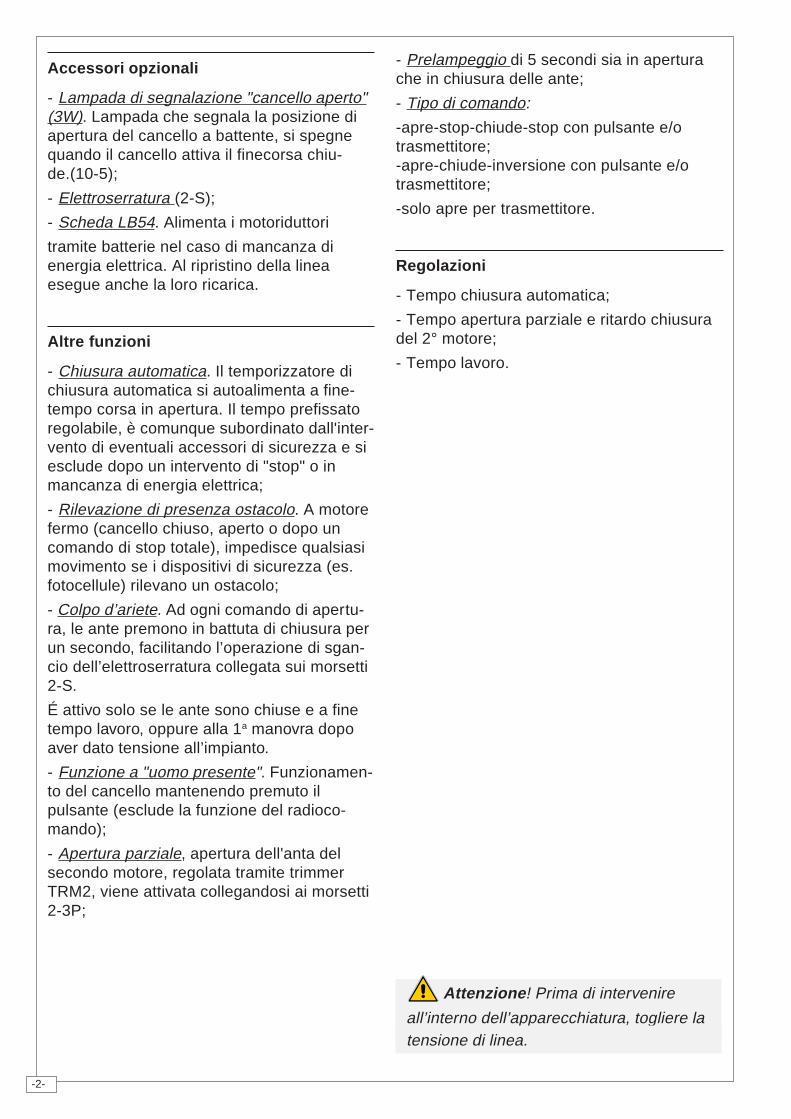
Il quadro comando ZL150N è adatto alcomando di automazioni per cancelli aa 2 battenti della serie FLEX alimentate a 24Vd.c., con potenza fino a 48W.
Progettato e costruito interamente dallaCAME S.p.A., risponde alle vigenti norme disicurezza con grado di protezione IP54.Contenitore in ABS.
Garantito 24 mesi salvo manomissioni.
Il circuito va alimentato con tensione di 230V(a.c.) sui morsetti L1-L2 e protetto in ingressocon un fusibile di linea da 1.6A.
I dispositivi di comando sono a bassatensione e protetti con fusibile da 1.6A,mentre il motoriduttore e l’elettroserraturasono protetti con fusibile da 5A.
La potenza complessiva degli accessori(24V) non deve superare i 40W.
Sicurezza
Le fotocellule possono essere collegate epredisposte per:
- Riapertura in fase di chiusura (2-C1), lefotocellule rilevando un ostacolo durante lafase di chiusura del cancello, provocanol'inversione di marcia fino alla completaapertura;
- Richiusura in fase di apertura (2-CX, dip8OFF-10OFF), le fotocellule rilevando unostacolo durante la fase di apertura delcancello, provocano l'inver-sione di marcia fino allacompleta chiusura;
- Stop parziale, arresto delcancello se in movimentocon conseguente predisposi-zione alla chiusura automati-
ca (2-CX, dip 8OFF-10ON);
- Stop totale (1-2), arresto del cancello conl'esclusione del ciclo di chiusura automatica;per riprendere il movimento bisogna agiresulla pulsantiera o sul radiocomando;
Nota: Se un contatto di sicurezza normal-mente chiuso (2-C1, 2-CX, 1-2) si apre, vienesegnalato dal lampeggio del LED segnalazio-ne.
18425
4
274
204
133
-2-
Accessori opzionali
- Lampada di segnalazione "cancello aperto"(3W). Lampada che segnala la posizione diapertura del cancello a battente, si spegnequando il cancello attiva il finecorsa chiu-de.(10-5);
- Elettroserratura (2-S);
- Scheda LB54. Alimenta i motoriduttori
tramite batterie nel caso di mancanza dienergia elettrica. Al ripristino della lineaesegue anche la loro ricarica.
Altre funzioni
- Chiusura automatica. Il temporizzatore dichiusura automatica si autoalimenta a fine-tempo corsa in apertura. Il tempo prefissatoregolabile, è comunque subordinato dall'inter-vento di eventuali accessori di sicurezza e siesclude dopo un intervento di "stop" o inmancanza di energia elettrica;
- Rilevazione di presenza ostacolo. A motorefermo (cancello chiuso, aperto o dopo uncomando di stop totale), impedisce qualsiasimovimento se i dispositivi di sicurezza (es.fotocellule) rilevano un ostacolo;
- Colpo d’ariete. Ad ogni comando di apertu-ra, le ante premono in battuta di chiusura perun secondo, facilitando l’operazione di sgan-cio dell’elettroserratura collegata sui morsetti2-S.
É attivo solo se le ante sono chiuse e a finetempo lavoro, oppure alla 1a manovra dopoaver dato tensione all’impianto.
- Funzione a "uomo presente". Funzionamen-to del cancello mantenendo premuto ilpulsante (esclude la funzione del radioco-mando);
- Apertura parziale, apertura dell'anta delsecondo motore, regolata tramite trimmerTRM2, viene attivata collegandosi ai morsetti2-3P;
Attenzione! Prima di intervenire
all’interno dell’apparecchiatura, togliere latensione di linea.
- Prelampeggio di 5 secondi sia in aperturache in chiusura delle ante;
- Tipo di comando:
-apre-stop-chiude-stop con pulsante e/otrasmettitore;-apre-chiude-inversione con pulsante e/otrasmettitore;
-solo apre per trasmettitore.
Regolazioni
- Tempo chiusura automatica;
- Tempo apertura parziale e ritardo chiusuradel 2° motore;
- Tempo lavoro.
-3-
GENERAL CHARACTERISTICS ENGLISHENGLISHENGLISHENGLISHENGLISH
Description
The ZL150N control panel is suitable for con-trolling automatic systems for the FLEX seriesswing gates powered by 24V d.c. with capacityup to 48 W.Designed and built entirely by CAME S.p.A. tomeet safety standards at an IP 54 protectionlevel. Housing in ABS.Guaranteed 24 months, unless tampered with.The circuit requires 230V (a.c.) at terminalblocks L1-L2 and the inlet is protected with 1,6Afuse. The command devices are low voltage andprotected by a 1.6A fuse, whereas thegearmotor and electric lock are protected by5A fuses.The accessories’ total wattage (24V) must notexceed 40W.
Safety
Photocells can be connected to obtain:- Re-opening during closure (2-C1), if the pho-tocells identify an obstacle while the gate isclosing, they will reverse the direction of move-ment until the gate is completely open;- Re-closing during opening (2-CX, dip 8OFF-10OFF), if the photocells identify an obstaclewhile the gate is opening, they will reverse thedirection of movement until the gate is com-pletely closed;- Partial stop, shutdown of moving gate, withactivation of an automatic closing cycle (2-CX,dip 8OFF-10ON);- Total stop (1-2), shutdown of gate movementwithout automatic closing; a pushbutton or ra-dio remote control must be actuated to resumemovement.NB: If an NC safety contact (2-C1, 2-CX, 1-2)is opened, the LED will flash to indicate thisfact.
Optional accessories
- Gate open pilot lamp (3W). A lamp that sig-nals the gate’s open position and that goes outwhen the gate is in the closed position. Con-nected to terminals 10-5.- Electric lock (2-S);- LB54 Board. Powers the reduction gearsthrough batteries in case of a power outage.After the power supply is restored, it also re-charges the batteries.
Other functions
- Automatic closing. The automatic closing timeris automatically activated at the end of the open-ing cycle. The preset, adjustable automaticclosing time is automatically interrupted by theactivation of any safety system, and is deacti-vated after a STOP command or in case ofpower failure;- Obstacle presence detection: When the mo-tor is stopped (gate is closed, open or half-openafter an emergency stop command), the trans-mitter and the control pushbutton will be deac-tivated if an obstacle is detected by one of thesafety devices (for example, the photocells);- Hammer movement. At every opening com-mand, the wings press the closing stop-ledgefor a second, thus facilitating the release op-eration of the electric lock connected to termi-nals 2-S.It is only active if the wings are closed and atthe end of the work time or at the 1st manoeu-vre after the system has been powered;- "Operator present" function: Gate operatesonly when the pushbutton is held down (theradio remote control system is deactivated);- Partial opening, second motor door opening,adjusted with TR2M trimmer; it is activated bycollecting to the terminals 2-3P;- Pre-flashing for 5 seconds, while the door isopening and closing;- Type of command:-open-stop-close-stop for pushbutton and ra-dio transmitter;-open-close-reverse for pushbutton and radiotransmitter;-open only for radio transmitter.
Adjustments
- Automatic closure time;- Partial opening time and delay in closing ofthe M2 motor;- Operating time.
Important! Disconnect the unit fromthe main power lines before carrying outany operation inside the unit.
-4-
CARACTÉRISTIQUES GÉNÉRALES FRANÇAISFRANÇAISFRANÇAISFRANÇAISFRANÇAIS
Description
Le armoire de commande ZL150N sert à com-mander les automatismes pour portails à bat-tant de la série FLEX alimentés à 24V c.c. avecune puissance jusqu’à 48W.Conçue et construite entièrement par CAMES.p.A., elle est conforme aux normes en vigueur.Boîtier en ABS avec degré de protection IP54.Garantie 24 mois sauf en cas d’endommage-ment.Le circuit doit être alimentée avec une tensionde 230V (c.a.) aux bornes L1-L2 et doit êtreprotégée à l’entrée par fusible de ligne de 1,6A.Les dispositifs de commande sont à basse ten-sion et sont protégés par un fusible de 1,6A,tandis que le motoréducteur et la serrure élec-trique sont protégés par un fusible de 5A.La puissance totale des accessoires (24V) nedoit pas dépasser 40W.
Sécurité
Il est possible de brancher des photocellules etde les programmer pour:- Réouverture en phase de fermeture (2-C1),les cellules photoélectriques provoquent l'inver-sion de marche jusqu'à l'ouverture complète sielles relèvent un obstacle durant la phase defermeture du portail;- Réfermeture en phase de ouverture (2-CX, dip8OFF-10OFF), les cellules photoélectriquesprovoquent l'inversion de marche jusqu'à la fer-meture complète si elles relèvent un obstacledurant la phase d'ouverture du portail;- Stop partiel, arrêt du portail, si en mouvement,et conséquente programmation pour la ferme-ture automatique (2-CX, dip 8OFF-10ON);- Stop total (1-2), arrêt du portail et désactiva-tion d’un éventuel cycle de fermeture automati-que; pour activer de nouveau le mouvement, ilfaut agir sur les boutons-poussoirs ou sur laradiocommande;Remarque: Le voyant de signalisation qui cli-gnote indique qu'un contact de sécuriténormalment fermé (2-C1, 2-CX, 1-2) s'ouvre.
Accessoires en option
- Lampe témoin portail ouvert (3W). Lampe quisignale la position d’ouverture du portail ets’éteint quand le portail est en position de fer-meture. Elle est branchée sur les bornes 10-5.- Serrure électrique (2-S);- Carte LB54. Elle alimente les motoréducteursà l’aide de batteries en cas de coupure de cou-rant. Elle recharge également les batteriesquand le courant est rétabli.
Autres fonctions
- Fermeture automatique. Le temporisateur defermeture automatique est autoalimenté à la findu temps de la course en ouverture. Le tempsréglable est programmé, cependant, il est su-bordonné à l’intervention d’éventuels accessoi-res de sécurité et il est exclu après une inter-vention de “stop” ou en cas de coupure de cou-rant;- Détection de présence d'obstacle. Quand lemoteur est arrêté (portail fermé, ouvert ou semi-ouvert, cette position est obtenue avec une com-mande de stop total), annule toute fonction del’émetteur ou du bouton-poussoir en cas d’obs-tacle détecté par les dispositifs de sécurité (ex.Photocellules) ;- Coup de bélier. Les vantaux appuient contrela butée de fermeture pendant une seconde àchaque commande d’ouverture en facilitantl’opération de déclenchement de la serrure élec-trique branchée aux bornes 2-S.Il n’est activé qu’à la fin du temps de travail etsi les vantaux sont fermés ou à la 1e manœu-vre après avoir coupé le courant de l’installa-tion;- Fonction “homme mort”. Fonctionnement duportail en maintenant appuyé le bouton-pous-soir (exclut la fonction de la radiocommande);- Ouverture partielle, ouverture de la porte dusecond moteur, réglée à l’aide du compensa-teur TR2M; elle est activée en se branchant auxbornes 2-3P;- Prè-clignotement de 5 secondes en ouverturecomme en fermeture de la porte;- Type de commande:-ouverte-stop-fermée-stop pour bouton-pous-soir et émetteur radio;-ouverture - fermeture - inversion pour bouton-poussoir et émetteur radio;-seulement ouverture pour émetteur radio.
Réglages
- Temps de fermeture automatique;- Temps d’ouverture partielle et retard en fer-meture du moteur M2;- Temps de fonctionnement;
Attention! Avant d’intervenir àl’intérieur de l’appareillage, couper latension de ligne.
-5-
ALLGEMEINE MERKMALE DEUTSCHDEUTSCHDEUTSCHDEUTSCHDEUTSCH
Beschreibung
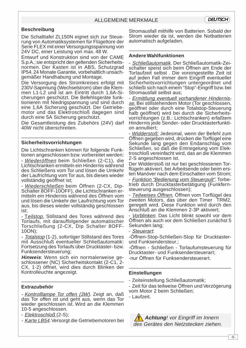
Die Schalttafel ZL150N eignet sich zur Steue-rung von Automatiksystemen für Flügeltore derSerie FLEX mit einer Versorgungsspannung von24V DC, einer Leistung von max. 48 W.Entwurf und Konstruktion sind von der CAMES.p.A.; sie entspricht den geltenden Sicherheits-normen. Der Kasten ist in ABS, SchutzgradIP54. 24 Monate Garantie, vorbehaltlich unsach-gemäßer Handhabung und Montage.Die Versorgung des Stromkreises erfolgt mit230V-Sapnnung (Wechselstrom) über die Klem-men L1-L2 und ist am Eintritt durch 1,6A-Si-cherungen geschützt. Die Befehlsgeräte funk-tionieren mit Niedrigspannung und sind durcheine 1,6A Sicherung geschützt. Der Getriebe-motor und das Elektroschloß dagegen sinddurch eine 5A Sicherung geschützt.Die Gesamtleistung des Zubehörs (24V) darf40W nicht überschreiten.
Sicherheitsvorrichtungen
Die Lichtschranken können für folgende Funk-tionen angeschlossen bzw. vorbereitet werden:- Wiederöffnen beim Schließen (2-C1), dieLichtschranken ermitteln ein Hindernis währenddes Schließens vom Tor und lösen die Umkehrder Laufrichtung vom Tor aus, bis dieses wiedervollständig geöffnet ist;- Wiederschließen beim Öffnen (2-CX, Dip-Schalter 8OFF-10OFF), die Lichtschranken er-mitteln ein Hindernis während des Öffnen vomund lösen die Umkehr der Laufrichtung vom Toraus, bis dieses wieder vollständig geschlossenist;- Teilstop, Stillstand des Tores während desTorlaufs, mit darauffolgender automatischerTorschließung (2-CX, Dip Schalter 8OFF-10ON);- Totalstop (1-2), sofortiger Stillstand des Toresmit Ausschluß eventueller Schließautomatik:Fortsetzung des Torlaufs über Drucktaster- bzw.Funksendersteuerung;Hinweis: Wenn sich ein normalerweise ge-schlossener (NC) Sicherheitskontakt (2-C1, 2-CX, 1-2) öffnet, wird dies durch Blinken derKontrolleuchte angezeigt.
Extrazubehör
- Kontrolllampe Tor offen (3W). Zeigt an, daßdas Tor offen ist und geht aus, wenn das Torwieder geschlossen ist. Wird an die Klemmen10-5 angeschlossen.- Elektroschloß (2-S);- Karte LB54. Versorgt die Getriebemotoren bei
Stromausfall mithilfe von Batterien. Sobald derStrom wieder da ist, werden die Notbatterienautomatisch aufgeladen.
Andere Wahlfunktionen
- Schließautomatik. Der Schließautomatik-Zei-schalter speist sich beim Öffnen am Ende derTorlaufzeit selbst . Die voreingestellte Zeit istauf jeden Fall immer dem Eingriff eventuellerSicherheitsvorrichtungen untergeordnet undschließt sich nach einem “Stop”-Eingriff bzw. beiStromausfall selbst aus;- Ermittlung eventuell vorhandener Hindernis-se. Bei stillstehendem Motor (Tor geschlossen,geöffnet oder durch eine Totalstop-Steuerunghalb geöffnet) wird bei durch die Sicherheits-vorrichtungen (z.B.: Lichtschranken) erfaßtemHindernis jede Sender- oder Drucktasterfunkti-on annulliert;- Widderstoß: Jedesmal, wenn der Befehl zumÖffnen gegeben wird, drücken die Torflügel eineSekunde lang gegen den Endanschlag vomSchließen, so daß die Entriegelung vom Elek-troschloß vereinfacht wird, das an die Klemmen2-S angeschlossen ist.Der Widderstoß ist nur bei geschlossenen Tor-flügeln aktiviert, bei Arbeitsende oder beim ers-ten Manöver nach dem Einschalten vom Strom;- Funktion “Bedienung vom Steuerpult”. Torbe-trieb durch Drucktasterbetätigung (Funkfern-steuerung ausgeschlossen);- Teilweises Öffnen, Öffnen vom Torflügel deszweiten Motors, das über den Timer TRM2,geregelt wird. Diese Funktion wird durch denAnschluß an die Klemmen 2-3P aktiviert;- Vorblinken. Das Licht blinkt sowohl vor demÖffnen als auch vor dem Schließen zunächst 5Sekunden lang;- Steuerart:-Öffnen-Stop-Schließen-Stop für Drucktaster-und Funksendersteur.;-Öffnen - Schließen - Torlaufumsteuerung fürDrucktaster- und Funksendersteuerart;-nur Öffnen für Funksendersteuerart.
Einstellungen
- Zeiteinstellung Schließautomatik;- Zeit für das teilweise Öffnen und Verzögerungvom Motor 2 beim Schließen;- Laufzeit.
Achtung! vor Eingriff im Innerndes Gerätes den Netzstecken ziehen.
-6-
CARACTERISTICAS GENERALES ESPAÑOLESPAÑOLESPAÑOLESPAÑOLESPAÑOL
Descripción
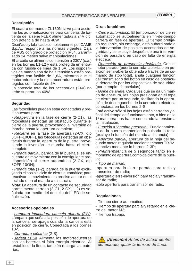
El cuadro de mando ZL150N sirve para accio-nar las automatizaciones para cancelas de ba-tiente de la serie FLEX alimentadas a 24V c.c.con potencia de hasta 48W.Diseñado y fabricado completamente por CAMES.p.A., responde a las normas vigentes. Cajade ABS con grado de protección IP54. Garanti-zado 24 meses salvo manipulaciones.El circuito se alimento con tensión a 230V (c.a.)en los bornes L1-L2 y está protegida en entra-da con fusible de línea de 1,6A. Los dispositi-vos de mando son de baja tensión y están pro-tegidos con fusible de 1,6A, mientras que elmotorreductor y la electrocerradura están pro-tegidos con fusible de 5A.La potencia total de los accesorios (24V) nodebe superar los 40W.
Seguridad
Las fotocélulas pueden estar conectadas y pre-dispuestas para:- Reapertura en la fase de cierre (2-C1), lasfotocélulas detectan un obstáculo durante elcierre de la puerta, provocando la inversión demarcha hasta la apertura completa;- Recierre en la fase de apertura (2-CX, dip8OFF-10OFF), las fotocélulas detectan un obs-táculo durante la apertura de la puerta, provo-cando la inversión de marcha hasta el cierrecompleto;- Parada parcial, parada de la puerta si se en-cuentra en movimiento con la consiguiente pre-disposición al cierre automático (2-CX, dip8OFF-10ON);- Parada total (1-2), parada de la puerta exclu-yendo el posible ciclo de cierre automático; parareactivar el movimiento es preciso actuar en elteclado o en el mando a distancia;Nota: La apertura de un contacto de seguridadnormalmente cerrado (2-C1, 2-CX, 1-2) es se-ñalada por medio del destello del LED de se-ñalización.
Accesorios opcionales
- Lámpara indicadora cancela abierta (3W).Lámpara que señala la posición de apertura dela cancela, se apaga cuando la cancela estáen posición de cierre. Conectada a los bornes10-5.- Cerradura eléctrica (2-S);- Tarjeta LB54. Alimenta los motorreductorescon las baterías si falta energía eléctrica. Alrestablecer la línea, también recarga las bate-rías.
Otras funciónes
- Cierre automático. El temporizador de cierreautomático se autoalimenta en fin-de-tiempocarrera en fase de apertura. El tiempo prefija-do regulable, sin embargo, está subordinado ala intervención de posibles accesorios de se-guridad y se excluye después de una interven-ción de parada o en caso de falta de energíaeléctrica;- Detección de presencia obstáculo. Con elmotor parado (puerta cerrada, abierta o en po-sición semi-abierta obtenida a través de un co-mando de stop total), anula cualquier funcióndel transmisor o del botón en caso de obstácu-lo detectado por los dispositivos de seguridad(por ejemplo: fotocélulas);- Golpe de ariete. Cada vez que se da un man-do de apertura, las hojas presionan en el topede cierre por un segundo, facilitando la opera-ción de desenganche de la cerradura eléctricaconectada en los bornes 2-S.Está activo sólo si las hojas están cerradas y alfinal del tiempo de funcionamiento, o bien en la1a maniobra tras haber conectado la tensión ala instalación;- Función a "hombre presente". Funcionamien-to de la puerta manteniendo pulsada la tecla(excluye la función del mando a distancia);- Apertura parcial, apertura de la hoja del se-gundo motor, regulada mediante trimmer TR2M;se activa mediante lo bornes 2-3P;- Preintermitencia de 5 segundos tanto en elmomento de apertura como de cierre de la puer-ta;- Tipo de mando;-apertura-parada-cierre-parada para tecla ytransmisor de radio;-apertura-cierre-inversión para tecla y transmi-sor de radio;-sólo apertura para transmisor de radio.
Regulaciones
- Tiempo cierre automático;- Tiempo de apertura parcial y retardo en el cie-rre del motor M2;- Tiempo trabajo.
¡Atención! Antes de actuar dentrodel aparato, quitar la tensión de línea.
-7-
QUADRO COMANDO - CONTROL PANEL - ARMOIRE DE COMMANDE - SCHALTTAFEL- CUADRO DE MANDO
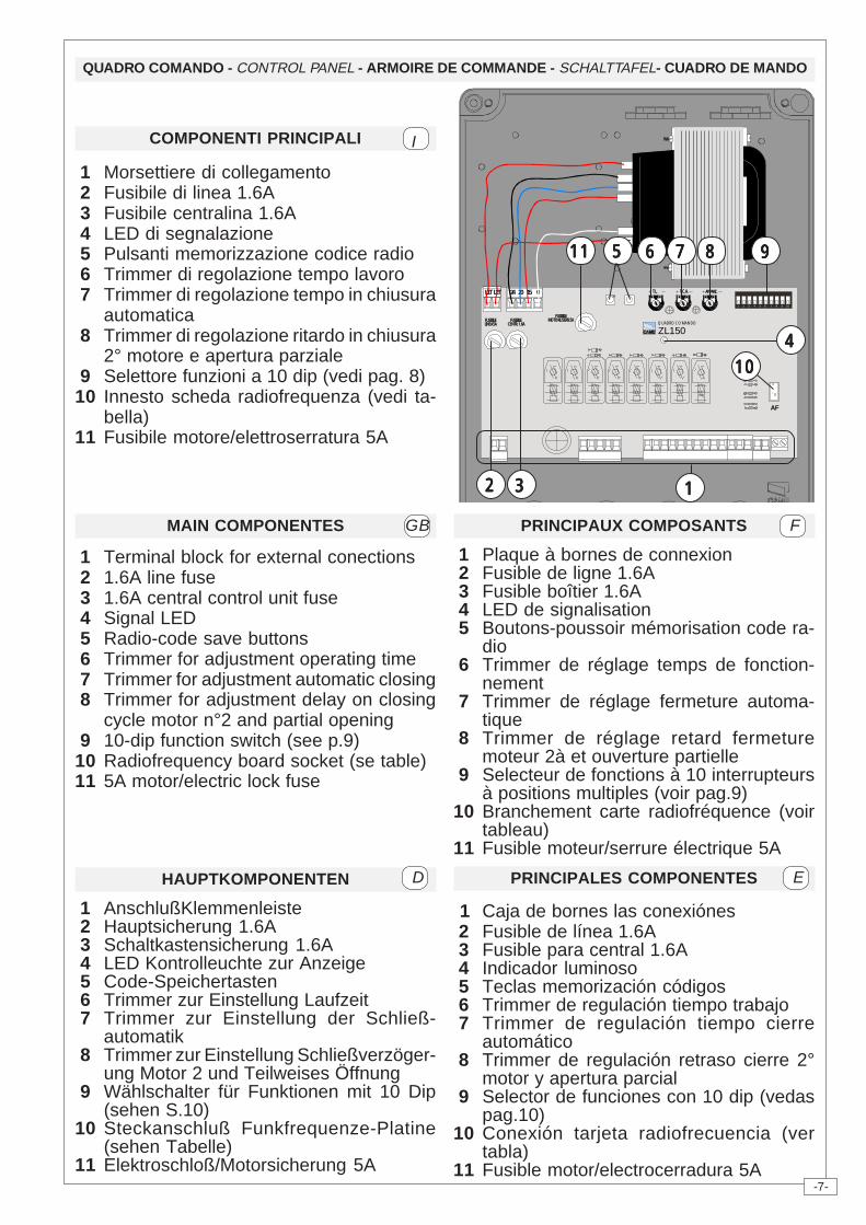
PRINCIPALES COMPONENTES
1 Caja de bornes las conexiónes 2 Fusible de línea 1.6A 3 Fusible para central 1.6A 4 Indicador luminoso 5 Teclas memorización códigos 6 Trimmer de regulación tiempo trabajo 7 Trimmer de regulación tiempo cierre
automático 8 Trimmer de regulación retraso cierre 2°
motor y apertura parcial 9 Selector de funciones con 10 dip (vedas
pag.10)10 Conexión tarjeta radiofrecuencia (ver
tabla)11 Fusible motor/electrocerradura 5A
EHAUPTKOMPONENTEN
1 AnschlußKlemmenleiste 2 Hauptsicherung 1.6A 3 Schaltkastensicherung 1.6A 4 LED Kontrolleuchte zur Anzeige 5 Code-Speichertasten 6 Trimmer zur Einstellung Laufzeit 7 Trimmer zur Einstellung der Schließ-
automatik 8 Trimmer zur Einstellung Schließverzöger-
ung Motor 2 und Teilweises Öffnung 9 Wählschalter für Funktionen mit 10 Dip
(sehen S.10)10 Steckanschluß Funkfrequenze-Platine
(sehen Tabelle)11 Elektroschloß/Motorsicherung 5A
D
PRINCIPAUX COMPOSANTS
1 Plaque à bornes de connexion 2 Fusible de ligne 1.6A 3 Fusible boîtier 1.6A 4 LED de signalisation 5 Boutons-poussoir mémorisation code ra-
dio 6 Trimmer de réglage temps de fonction-
nement 7 Trimmer de réglage fermeture automa-
tique 8 Trimmer de réglage retard fermeture
moteur 2à et ouverture partielle 9 Selecteur de fonctions à 10 interrupteurs
à positions multiples (voir pag.9)10 Branchement carte radiofréquence (voir
tableau)11 Fusible moteur/serrure électrique 5A
FMAIN COMPONENTES
1 Terminal block for external conections 2 1.6A line fuse 3 1.6A central control unit fuse 4 Signal LED 5 Radio-code save buttons 6 Trimmer for adjustment operating time 7 Trimmer for adjustment automatic closing 8 Trimmer for adjustment delay on closing
cycle motor n°2 and partial opening 9 10-dip function switch (see p.9)10 Radiofrequency board socket (se table)11 5A motor/electric lock fuse
GB
COMPONENTI PRINCIPALI
1 Morsettiere di collegamento 2 Fusibile di linea 1.6A 3 Fusibile centralina 1.6A 4 LED di segnalazione 5 Pulsanti memorizzazione codice radio 6 Trimmer di regolazione tempo lavoro 7 Trimmer di regolazione tempo in chiusura
automatica 8 Trimmer di regolazione ritardo in chiusura
2° motore e apertura parziale 9 Selettore funzioni a 10 dip (vedi pag. 8)10 Innesto scheda radiofrequenza (vedi ta-
bella)11 Fusibile motore/elettroserratura 5A
I
AF
ZL150QUADRO COMANDO
T.L. T.C.A. AP.PARZ.
21 3 4 5 6 7 8 9 10
O N
FUSIBILELINEA 5A
FUSIBILECENTR. 1.6A
01524 20L1T L2T
FUSIBILEMOTORE/SERR. 5A
22222 33333 11111
444441010101010
99999888887777766666555551111111111
-8-
AF
ZL150QUADRO COMANDO
T.L. T.C.A. AP.PARZ.
21 3 4 5 6 7 8 9 10
ON
FUSIBILELINEA 5A
FUSIBILECENTR. 3.15A
L1T L2T 01524 20
SELEZIONI FUNZIONI - SELECTION OF FUNCTIONS - SÉLECTION FONCTIONSFUNKTIONSWAHL - SELECCIÓN DE LAS FUNCIONES
DIP-SWITCH 10 VIE
10-WAY DIP-SWITCH
DIP-SWITCH 10 VOIES
ZEHNWEG-DIP-SWITCH
DIP-SWITCH 10 VÍAS
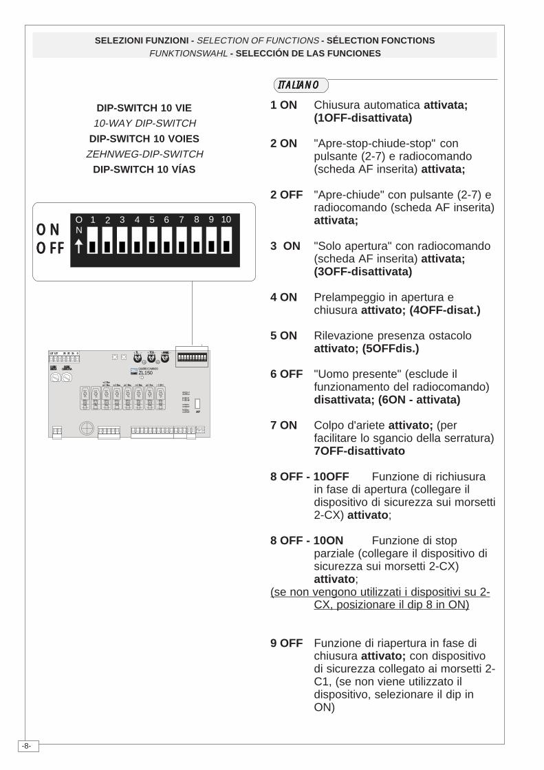
1 ON Chiusura automatica attivata;(1OFF-disattivata)
2 ON "Apre-stop-chiude-stop" conpulsante (2-7) e radiocomando(scheda AF inserita) attivata;
2 OFF "Apre-chiude" con pulsante (2-7) eradiocomando (scheda AF inserita)attivata;
3 ON "Solo apertura" con radiocomando(scheda AF inserita) attivata;(3OFF-disattivata)
4 ON Prelampeggio in apertura echiusura attivato; (4OFF-disat.)
5 ON Rilevazione presenza ostacoloattivato; (5OFFdis.)
6 OFF "Uomo presente" (esclude ilfunzionamento del radiocomando)disattivata; (6ON - attivata)
7 ON Colpo d'ariete attivato; (perfacilitare lo sgancio della serratura)7OFF-disattivato
8 OFF - 10OFF Funzione di richiusurain fase di apertura (collegare ildispositivo di sicurezza sui morsetti2-CX) attivato;
8 OFF - 10ON Funzione di stopparziale (collegare il dispositivo disicurezza sui morsetti 2-CX)attivato;
(se non vengono utilizzati i dispositivi su 2-CX, posizionare il dip 8 in ON)
9 OFF Funzione di riapertura in fase dichiusura attivato; con dispositivodi sicurezza collegato ai morsetti 2-C1, (se non viene utilizzato ildispositivo, selezionare il dip inON)
21 3 4 5 6 7 8 9 10ONONONONONON
OFFOFFOFFOFFOFF
ITALIANOITALIANOITALIANOITALIANOITALIANO
-9-
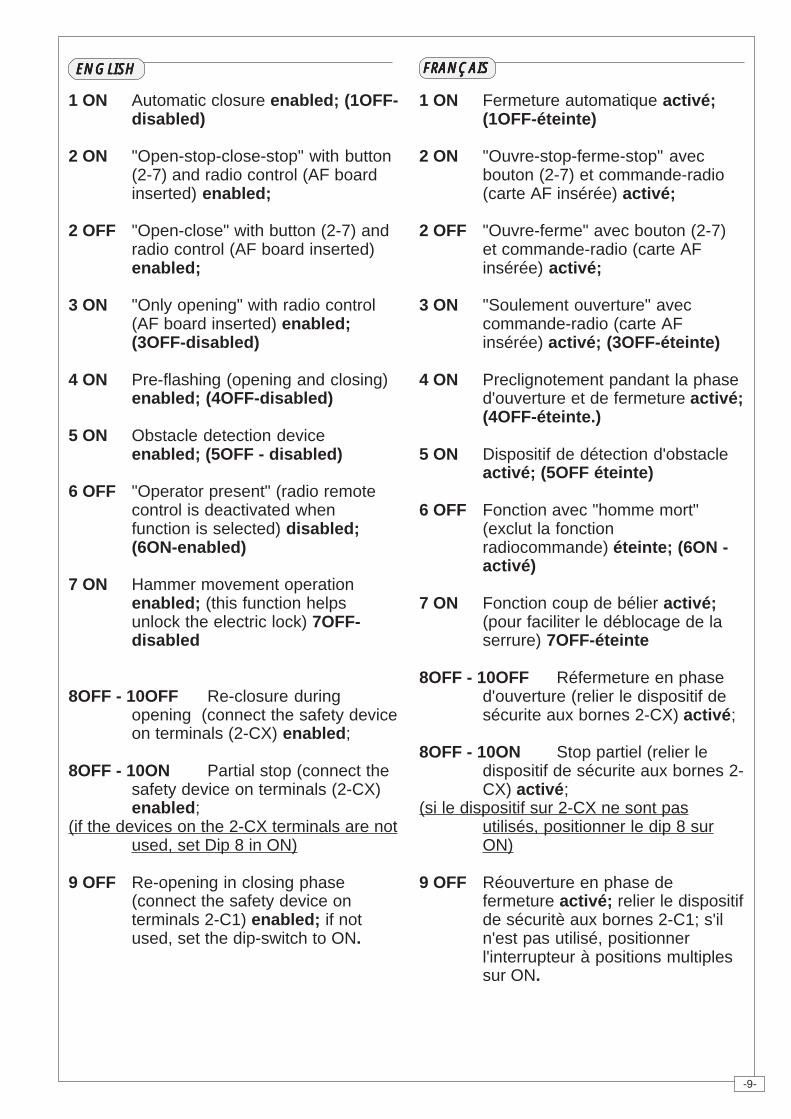
1 ON Automatic closure enabled; (1OFF-disabled)
2 ON "Open-stop-close-stop" with button(2-7) and radio control (AF boardinserted) enabled;
2 OFF "Open-close" with button (2-7) andradio control (AF board inserted)enabled;
3 ON "Only opening" with radio control(AF board inserted) enabled;(3OFF-disabled)
4 ON Pre-flashing (opening and closing)enabled; (4OFF-disabled)
5 ON Obstacle detection deviceenabled; (5OFF - disabled)
6 OFF "Operator present" (radio remotecontrol is deactivated whenfunction is selected) disabled;(6ON-enabled)
7 ON Hammer movement operationenabled; (this function helpsunlock the electric lock) 7OFF-disabled
8OFF - 10OFF Re-closure duringopening (connect the safety deviceon terminals (2-CX) enabled;
8OFF - 10ON Partial stop (connect thesafety device on terminals (2-CX)enabled;
(if the devices on the 2-CX terminals are notused, set Dip 8 in ON)
9 OFF Re-opening in closing phase(connect the safety device onterminals 2-C1) enabled; if notused, set the dip-switch to ON.
1 ON Fermeture automatique activé;(1OFF-éteinte)
2 ON "Ouvre-stop-ferme-stop" avecbouton (2-7) et commande-radio(carte AF insérée) activé;
2 OFF "Ouvre-ferme" avec bouton (2-7)et commande-radio (carte AFinsérée) activé;
3 ON "Soulement ouverture" aveccommande-radio (carte AFinsérée) activé; (3OFF-éteinte)
4 ON Preclignotement pandant la phased'ouverture et de fermeture activé;(4OFF-éteinte.)
5 ON Dispositif de détection d'obstacleactivé; (5OFF éteinte)
6 OFF Fonction avec "homme mort"(exclut la fonctionradiocommande) éteinte; (6ON -activé)
7 ON Fonction coup de bélier activé;(pour faciliter le déblocage de laserrure) 7OFF-éteinte
8OFF - 10OFF Réfermeture en phased'ouverture (relier le dispositif desécurite aux bornes 2-CX) activé;
8OFF - 10ON Stop partiel (relier ledispositif de sécurite aux bornes 2-CX) activé;
(si le dispositif sur 2-CX ne sont pasutilisés, positionner le dip 8 surON)
9 OFF Réouverture en phase defermeture activé; relier le dispositifde sécuritè aux bornes 2-C1; s'iln'est pas utilisé, positionnerl'interrupteur à positions multiplessur ON.
ENGLISHENGLISHENGLISHENGLISHENGLISH FRANÇAISFRANÇAISFRANÇAISFRANÇAISFRANÇAIS
-10-
DEUTSCHDEUTSCHDEUTSCHDEUTSCHDEUTSCH
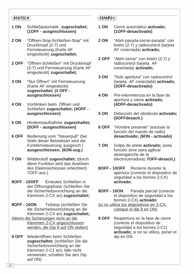
1 ON Schließautomatik zugeschaltet;(1OFF - ausgeschlossen)
2 ON "Öffnen-Stop-Schließen-Stop" mitDruckknopf (2-7) undFernsteuerung (Karte AFeingesteckt) zugeschaltet;
2 OFF "Öffnen-Schließen" mit Druckknopf(2-7) und Fernsteuerung (Karte AFeingesteckt) zugeschaltet;
3 ON "Nur Öffnen" mit Fernsteuerung(Karte AF eingesteckt)zugeschaltet; (3 OFF -ausgeschlossen)
4 ON Vorblinken beim Öffnen undSchließen zugeschaltet; (4OFF -ausgeschlossen)
5 ON Hindemisaufnahme zugeschaltet;(5OFF - ausgeschlossen)
6 OFF Bedienung vom "Steuerpult" (beiWahl dieser Betriebsart wird dieFunkfernsteuerung ausgesch.)ausgeschlossen; (6ON-zug.)
7 ON Widderstoß zugeschaltet; (durchdiese Funktion wird das Auslösendes Elektroschlosses erleichtert)7OFF-aus.)
8OFF - 10OFF Erneutes Schließen inder Öffnungsphase (schließen Siedie Sicherheitsvorrichtung an dieKlemmen 2-CX an) zugeschaltet;
8OFF - 10ON Teilstop (schließen Siedie Sicherheitsvorrichtung an dieKlemmen 2-CX an) zugeschaltet;
(Wenn die Sicherungen nicht an dieKlemmen 2-CX angeschlossenwerden, die Dip 8 auf ON stellen)
9 OFF Wiederöffnen beim Schließenzugeschaltet; (schließen Sie dieSicherheitsvorrichtung an dieKlemmen 2-C1 an); falls nichtverwendet, schalten Sie den Dipauf ON)
ESPAÑOLESPAÑOLESPAÑOLESPAÑOLESPAÑOL
1 ON Cierre automático activado;(1OFF-desactivado)
2 ON "Abrir-parada-cerrar-parada" conbotón (2-7) y radiocontrol (tarjetaAF conectada) activado;
2 OFF "Abrir-cerrar" con botón (2-7) yradiocontrol (tarjeta AFconectada) activado;
3 ON "Solo apertura" con radiocontrol(tarjeta AF conectada) activado;(3OFF-desactivado)
4 ON Pre-intermitencia en la fase deapertura y cierre activado;(4OFF-desactivado)
5 ON Detección del obstáculo activado;(5OFFdesacti.)
6 OFF "Hombre presente" (escluye lafunción del mando de radio)desactivado; (6ON - activado)
7 ON Golpe de ariete activado; (estafunción sirve para agilizardesenganche de laelectrocerradura) 7OFF-desacti.)
8OFF - 10OFF Recierre durante laapertura (conecte el dispositivo deseguridad a los bornes 2-CX)activado;
8OFF - 10ON Parada parcial (conecteel dispositivo de seguridad a losbornes 2-CX) activado;
(si no utiliza los dispositivos en 2-CX,coloque el dip 8 en ON)
9 OFF Reapertura en la fase de cierre(conecte el dispositivo deseguridad a los bornes 2-C1)activado; si no se utiliza, poner eldip en ON
-11-
AF
ZL150QUADRO COMANDO
T.L. T.C.A. AP.PARZ.
21 3 4 5 6 7 8 9 10
ON
FUSIBILELINEA 5A
FUSIBILECENTR. 1.6A
01524 20L1T L2T
FUSIBILEMOTORE/SERR. 5A
REGOLAZIONI - ADJUSTMENTS - RÉGLAGES - EINSTELLUNGEN - REGULACIONES
ITALIANOITALIANOITALIANOITALIANOITALIANO
FRANÇAISFRANÇAISFRANÇAISFRANÇAISFRANÇAIS
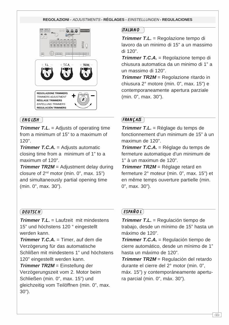
Trimmer T.L. = Regolazione tempo dilavoro da un minimo di 15” a un massimodi 120”.Trimmer T.C.A. = Regolazione tempo dichiusura automatica da un minimo di 1” aun massimo di 120”.Trimmer TR2M = Regolazione ritardo inchiusura 2° motore (min. 0”, max. 15”) econtemporaneamente apertura parziale(min. 0”, max. 30”).
ENGLISHENGLISHENGLISHENGLISHENGLISH
ESPAÑOLESPAÑOLESPAÑOLESPAÑOLESPAÑOLDEUTSCHDEUTSCHDEUTSCHDEUTSCHDEUTSCH
REGULACIÓN TRIMMERSEINTELLUNG TRIMMERS
RÉGLAGE TRIMMERSTRIMMERS ADJUSTMENTREGOLAZIONE TRIMMERS
T.L. T.C.A. TR2M.
Trimmer T.L. = Adjusts of operating timefrom a minimum of 15” to a maximum of120”.Trimmer T.C.A. = Adjusts automaticclosing time from a minimum of 1” to amaximum of 120”.Trimmer TR2M = Adjustment delay duringclosure of 2nd motor (min. 0”, max. 15”)and simultaneously partial opening time(min. 0”, max. 30”).
Trimmer T.L. = Réglage du temps defonctionnement d'un minimum de 15” à unmaximun de 120”.Trimmer T.C.A. = Réglage du temps defermeture automatique d'un minimum de1” à un maximun de 120”.Trimmer TR2M = Réglage retard enfermeture 2° moteur (min. 0”, max. 15”) eten même temps ouverture partielle (min.0”, max. 30”).
Trimmer T.L. = Laufzeit mit mindestens15” und höchstens 120 “ eingestelltwerden kann.Trimmer T.C.A. = Timer, auf dem dieVerzögerung für das automatischeSchlißen mit mindestens 1” und höchstens120” eingestellt werden kann.Trimmer TR2M = Einstellung derVerzögerungszeit vom 2. Motor beimSchließen (min. 0”, max. 15”) undgleichzeitig vom Teilöffnen (min. 0”, max.30”).
Trimmer T.L. = Regulación tiempo detrabajo, desde un mínimo de 15” hasta unmáximo de 120”.Trimmer T.C.A. = Regulación tiempo decierre automático, desde un mínimo de 1”hasta un máximo de 120”.Trimmer TR2M = Regulación del retardodurante el cierre del 2° motor (min. 0”,máx. 15”) y contemporáneamente apertu-ra parcial (min. 0”, máx. 30”).
-12-
1010101010
5 5 5 5 5
COLLEGAMENTI ELETTRICI - ELECTRICAL CONNECTIONS - BRANCHEMENTS ÉLECTRIQUES ELEKRISCHE ANSCHLÜSSE - CONEXIONES ELÉCTRICAS
1010101010
E E E E E
M1M1M1M1M1
N1N1N1N1N1
L1L1L1L1L1
L2L2L2L2L2
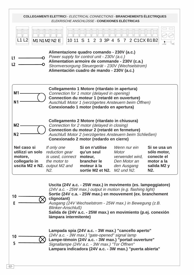
Alimentazione quadro comando - 230V (a.c.)Power supply for control unit - 230V (a.c.)Alimentation armoire de commande - 230V (c.a.)Stromversorgung Steuergerät - 230V (Wechselstrom)Alimentación cuadro de mando - 230V (a.c.)
Collegamento 1 Motore (ritardato in apertura)Connection for 1 motor (delayed in opening)Connection du moteur 1 (retardé en ouverture)Auschluß Motor 1 (verzögertes Ansteuern beim Öffnen)Conexionado 1 motor (redardo en apertura)
Collegamento 2 Motore (ritardato in chiusura)Connection for 2 motor (delayed in closing)Connection du moteur 2 (retardé en fermeture)Auschluß Motor 2 (verzögertes Ansteuern beim Schließen)Conexionado 2 motor (redardo en cierre)
Uscita (24V a.c. - 25W max.) in movimento (es. lampeggiatore)(24V a.c. - 25W max.) output in motion (e.g. flashing light)Sortie (24V c.a. - 25W max.) en mouvement (ex. branchementclignotant)Ausgang (24V Wechselstrom - 25W max.) in Bewegung (z.B.Blinker-Anschluß)Salida de (24V a.c. - 25W max.) en movimiento (p.ej. conexiónlámpara intermitente)
Lampada spia (24V a.c. - 3W max.) "cancello aperto"(24V a.c. - 3W max.) "gate-opened" signal lampLampe-témoin (24V a.c. - 3W max.) "portail ouverture"Signallampe (24V a.c. - 3W max.) "Tor Öffnen"Lampara indicadora (24V a.c. - 3W max.) "puerta abierta"
Nel caso siutilizzi un solomotore,collegarlo inuscita M2 e N2.
If only onereduction gearis used, connectthe motor tooutput M2 andN2.
Si on n’utilisequ’un seulmoteur,brancher lemoteur à lasortie M2 et N2.
Wenn nur einMotorverwendet wird,Den Motor anden AusgangM2 und N2.
Si se usa unsólo motor,conecte elmotor a lasalida M2 yN2.
L1 L2 M1 N1M2 N2 E 10 11 S 1 2 3 3P 4 5 7 2 C1CX B1B2
M2M2M2M2M2
N2N2N2N2N2
-13-
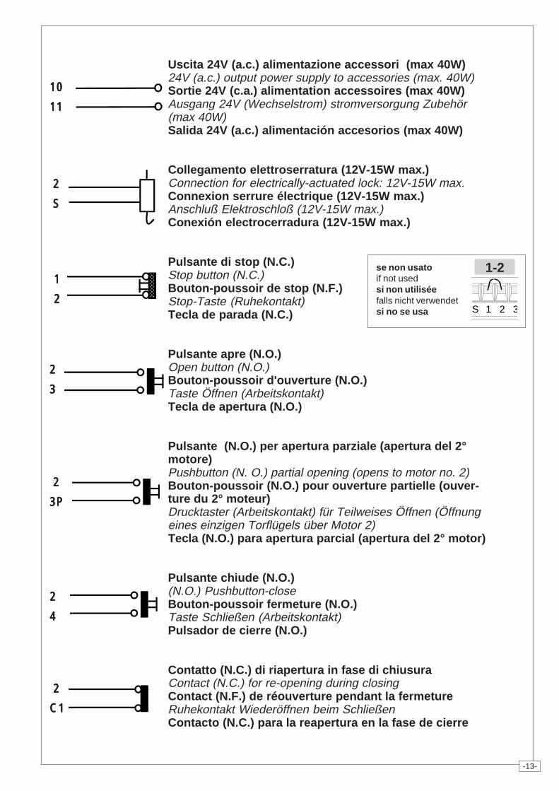
Uscita 24V (a.c.) alimentazione accessori (max 40W)24V (a.c.) output power supply to accessories (max. 40W)Sortie 24V (c.a.) alimentation accessoires (max 40W)Ausgang 24V (Wechselstrom) stromversorgung Zubehör(max 40W)Salida 24V (a.c.) alimentación accesorios (max 40W)
Collegamento elettroserratura (12V-15W max.)Connection for electrically-actuated lock: 12V-15W max.Connexion serrure électrique (12V-15W max.)Anschluß Elektroschloß (12V-15W max.)Conexión electrocerradura (12V-15W max.)
Pulsante di stop (N.C.)Stop button (N.C.)Bouton-poussoir de stop (N.F.)Stop-Taste (Ruhekontakt)Tecla de parada (N.C.)
Pulsante apre (N.O.)Open button (N.O.)Bouton-poussoir d'ouverture (N.O.)Taste Öffnen (Arbeitskontakt)Tecla de apertura (N.O.)
Pulsante (N.O.) per apertura parziale (apertura del 2°motore)Pushbutton (N. O.) partial opening (opens to motor no. 2)Bouton-poussoir (N.O.) pour ouverture partielle (ouver-ture du 2° moteur)Drucktaster (Arbeitskontakt) für Teilweises Öffnen (Öffnungeines einzigen Torflügels über Motor 2)Tecla (N.O.) para apertura parcial (apertura del 2° motor)
Pulsante chiude (N.O.)(N.O.) Pushbutton-closeBouton-poussoir fermeture (N.O.)Taste Schließen (Arbeitskontakt)Pulsador de cierre (N.O.)
Contatto (N.C.) di riapertura in fase di chiusuraContact (N.C.) for re-opening during closingContact (N.F.) de réouverture pendant la fermetureRuhekontakt Wiederöffnen beim SchließenContacto (N.C.) para la reapertura en la fase de cierre
1 1 1 1 1
2 2 2 2 2
���������������
1010101010
1111111111
2 2 2 2 2
S S S S S
22222
33333
2 2 2 2 2
3P3P3P3P3P
22222
44444
2 2 2 2 2
C1C1C1C1C1
S 1 2 3
1-2se non usatoif not usedsi non utiliséefalls nicht verwendetsi no se usa
-14-
���
2 2 2 2 2
CXCXCXCXCX
B1B1B1B1B1
B2B2B2B2B2
22222
77777
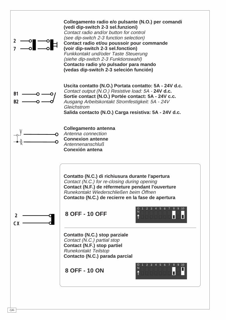
Collegamento radio e/o pulsante (N.O.) per comandi(vedi dip-switch 2-3 sel.funzioni)Contact radio and/or button for control(see dip-switch 2-3 function selection)Contact radio et/ou poussoir pour commande(voir dip-switch 2-3 sel.fonction)Funkkontakt und/oder Taste Steuerung(siehe dip-switch 2-3 Funktionswahl)Contacto radio y/o pulsador para mando(vedas dip-switch 2-3 seleción función)
Uscita contatto (N.O.) Portata contatto: 5A - 24V d.c.Contact output (N.O.) Resistive load: 5A - 24V d.c.Sortie contact (N.O.) Portée contact: 5A - 24V c.c.Ausgang Arbeitskontakt Stromfestigkeit: 5A - 24VGleichstromSalida contacto (N.O.) Carga resistiva: 5A - 24V d.c.
Collegamento antennaAntenna connectionConnexion antenneAntennenanschlußConexión antena
Contatto (N.C.) di richiusura durante l'aperturaContact (N.C.) for re-closing during openingContact (N.F.) de réfermeture pendant l'ouvertureRunekontakt Wiederschließen beim ÖffnenContacto (N.C.) de recierre en la fase de apertura
Contatto (N.C.) stop parzialeContact (N.C.) partial stopContact (N.F.) stop partielRunekontakt TeilstopContacto (N.C.) parada parcial
21 3 4 5 6 7 8 9 10ON
21 3 4 5 6 7 8 9 10ON
8 OFF - 10 OFF
8 OFF - 10 ON
-15-
PAGINA LASCIATA INTENZIONALMENTE BIANCATHIS PAGE LEFT INTENTIONALLY BLANK
NOUS AVONS LAISSÉ EXPRÉS CETTE PAGE BLANCHEDIE SEITE WURDE ABSICHLICH LEER GELASSEN
PÁGINA DEJADA EN BLANCO INTENCIONALMENTE
-16-
PROGRAMMAZIONE DEL RADIOCOMANDO / PROGRAMMING THE REMOTE CONTROLPROGRAMMATION DE LA COMMANDE RADIO
PROGRAMMIERUNG DER FUNKFERNSTEUERUNG / PROGRAMACION DEL MANDO A DISTANCIA
ENGLISH
PROCEDURE
A. insert anAF card.
B. encodetransmitter/s.
C. store codein themotherboard.
FRANCAIS
PROCEDURE
A. placer unecarte AF.
B. codifier le/sémetteur/s.
C. mémoriserlacodificationsur la cartebase.
DEUTSCH
PROZEDUR
A. Stecken Sieeine KarteAF.
B. CodierenSie den/dieSender.
C. SpeichernSie dieCodierungauf derGrundplatine.
ITALIANO
PROCEDURA
A. inserire unascheda AF.
B. codificare il/i trasmettito-re/i.
C. memorizza-re la codificasulla schedabase.
ESPAÑOL
PROCEDIMIENTO
A. introduciruna tarjetaAF.
B. codificar el/lostransmisor/es.
C. memorizarlacodificaciónen la tarjetabase.
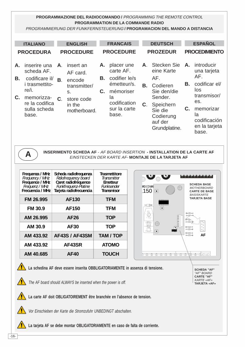
INSERIMENTO SCHEDA AF - AF BOARD INSERTION - INSTALLATION DE LA CARTE AFEINSTECKEN DER KARTE AF- MONTAJE DE LA TARJETA AFA
Frequenza / MHz Frequency / MHz Frequence / MHzFrequenz / MHz
Frecuencia / MHz
Scheda radiofrequenzaRdiofrequency board Caret radiofréquenceFunkfrequenz-Platine
Tarjeta radiofrecuencia
Trasmettitore Transmitter Emetteur
Funksender Transmisor
FM 26.995 AF130 TFM
FM 30.9 AF150 TFM
AM 26.995 AF26 TOP
AM 30.9 AF30 TOP
AM 433.92 AF43S / AF43SM TAM / TOP
AM 433.92 AF43SR ATOMO
AM 40.685 AF40 TOUCH
AF
L150DRO COMANDO
21 3 4 5 6 7 8 9 10
SCHEDA BASEMOTHERBOARDCARTE DE BASEBASISKARTETARJETA BASE
SCHEDA "AF""AF" BOARDCARTE "AF"KARTE «AF»TARJETA «AF»
La schedina AF deve essere inserita OBBLIGATORIAMENTE in assenza di tensione.
The AF board should ALWAYS be inserted when the power is off.
La carte AF doit OBLIGATOIREMENT être branchée en l’absence de tension.
Vor Einschieben der Karte die Stromzufuhr UNBEDINGT abschalten.
La tarjeta AF se debe montar OBLIGATORIAMENTE en caso de falta de corriente.
-17-
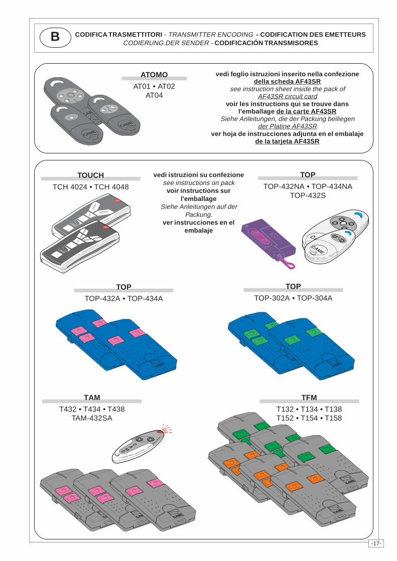
CODIFICA TRASMETTITORI - TRANSMITTER ENCODING - CODIFICATION DES EMETTEURSCODIERUNG DER SENDER - CODIFICACIÓN TRANSMISORES
B
vedi istruzioni su confezionesee instructions on pack
voir instructions surl'emballage
Siehe Anleitungen auf derPackung.
ver instrucciones en elembalaje
CAME
CAMECAME
CAME
CAME
CAME
CAME
CAME
CAME
CAME
vedi foglio istruzioni inserito nella confezionedella scheda AF43SR
see instruction sheet inside the pack ofAF43SR circuit card
voir les instructions qui se trouve dansl'emballage de la carte AF43SR
Siehe Anleitungen, die der Packung beiliegender Platine AF43SR
ver hoja de instrucciones adjunta en el embalajede la tarjeta AF43SR
ATOMO
AT01 • AT02AT04
TOUCH
TCH 4024 • TCH 4048
TOP
TOP-432NA • TOP-434NATOP-432S
TOP
TOP-302A • TOP-304A
TOP
TOP-432A • TOP-434A
TAM
T432 • T434 • T438TAM-432SA
TFM
T132 • T134 • T138T152 • T154 • T158
CAME
CAMECAME
CAMECAME
CAME
-18-
ITALIANO
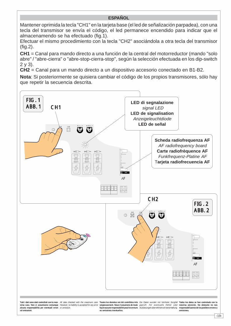
Tenere premuto il tasto "CH1" sulla scheda base (il led di segnalazione lampeggia), con untasto del trasmettitore si invia il codice, il led rimarrà acceso a segnalare l'avvenutamemorizzazione (vedi fig.1, pag.20). Eseguire la stessa procedura con il tasto "CH2"associandolo con un altro tasto del trasmettitore (fig.2).CH1 = Canale per comandi diretti ad una funzione della centralina del motoriduttore (comando"solo apre" / "apre-chiude" oppure "apre-stop-chiude-stop", a seconda della selezioneeffetuata sui dip-switch 2 e 3).CH2 = Canale per comandi diretti ad un dispositivo accessorio collegato su B1-B2.N.B.: Se in seguito si vuol cambiare codice, basta ripetere la sequenza descritta.
DEUTSCH
Die Taste "CH1" gedrückt halten und nach Aufleuchten der Anzeige-Leuchtdiode über denSender-Taster einen Steuerimpuls ausführen: ein kurzes Blinken der Led zeigt die erfolgteSpeicherung an (Abb.1, Seite 20). Gehen Sie ebenso mit Taste "CH2" vor und ordnen sie ihreine andere Taste des Senders zu (Abb.2).CH1 = Kanal für die Direktsteuerung einer Funktion des Getriebemotor-Schaltkastens(Steuerung "nur Öffnen" / "Öffnen-Schließen" bzw. "Öffnen-Stp-Schließen-Stop", je nachüber Dip-Switch 2 und 3 ausgeführter Wahl).CH2 = Kanal für Direktsteuerung eines über B1-B2 angeschlossenen Zubehörs.HINWEIS: bei eventuell erwünschter Sender codeänderung ist der beschriebene Vorgang zuwiederholen.
ENGLISH
Keep the CH1 key pressed on the base card (the signal LED will flash), and with a key on thetransmitter the code is sent, the LED will remain lit to signal the successful saving of the code(figure 1, pag.20).Perform the same procedure with the "CH2" key, associating it with another transmitter key(fig. 2).CH1 = Channel for direct control of one function performed by the control unit on the gear motor("open only" / "open-close" or "open-stop-close-stop", depending on the position of dipswitches 2 and 3).CH2 = Channel for direct control of an accessory connected across B1-B2.N.B. If you wish to change the code on your transmitters in the future, simply repeat theprocedure described above.
FRANCAIS
Appuyer sur la touche "CH1" sur la carte de base (le led de signalisation clignote), avec unetouche du emetteur on envoie le code, le led reste allumé pour signaler que la mémorisations'est effectuèe (fig.1, pag.20).Suivre la même procédure avec la touche "CH2" en l'associant avec une autre touche duemetteur (fig.2).CH1 = Canal pour obtenir la commande directe d'une fonction du boîtier du motoréducteur(commande "uniquement ouverture" / "ouverture-fermeture" ou "ouverte-stop-ferme-stop" enfonction de la sélection effectuée sur les dip-switchs 2 et 3).CH2 = Canal pour obtenir la commande directe d'un dispositif accessoire branché sur B1-B2.N.B.: Si, successivement, on veut changer le code des émetteur, il suffit de répéter laséquence décrite ci-dessus.
MEMORIZZAZIONE CODICE - CODE STORAGE - MEMORISATION DU CODESPEICHERN VOM CODE - MEMORIZACIÓN CÓDIGOC
-19-
FIG. 1FIG. 1FIG. 1FIG. 1FIG. 1ABB. 1ABB. 1ABB. 1ABB. 1ABB. 1
LED di segnalazione signal LED
LED de signalisationAnzeigeleuchtdiode
LED de señal
Scheda radiofrequenza AFAF radiofrequency board
Carte radiofrèquence AFFunkfrequenz-Platine AF
Tarjeta radiofrecuencia AF
ESPAÑOL
Mantener oprimida la tecla "CH1" en la tarjeta base (el led de señalización parpadea), con unatecla del transmisor se envía el código, el led permanece encendido para indicar que elalmacenamendo se ha efectuado (fig.1).Efectuar el mismo procedimiento con la tecla "CH2" asociándola a otra tecla del transmisor(fig.2).CH1 = Canal para mando directo a una función de la central del motorreductor (mando "soloabre" / "abre-cierra" o "abre-stop-cierra-stop", según la selección efectuada en los dip-switch2 y 3).CH2 = Canal para un mando directo a un dispositivo accesorio conectado en B1-B2.Nota: Si posteriormente se quisiera cambiar el código de los propios transmisores, sólo hayque repetir la secuencia descrita.
CH2CH2CH2CH2CH2
CH1CH1CH1CH1CH1
FIG. 2FIG. 2FIG. 2FIG. 2FIG. 2ABB. 2ABB. 2ABB. 2ABB. 2ABB. 2
Tutti i dati sono stati controllati con la mas-sima cura. Non ci assumiamo comunquealcuna responsabilità per eventuali erroriod omissioni.
All data checked with the maximum care.However, no liability is accepted for any erroror omission.
Toutes les données ont été contrôlées trèssoigneusement. Nous n’assumons de toutefaçon aucune responsabilité pour les erreursou omissions éventuelles.
Die Daten wurden mit höchster Sorgfaltgeprüft. Für eventuelle Fehler oderAuslassungen übernehmen wir keine Haftung.
Todos los datos se han controlado con lamáxima atención. No obstante no nosresponsabilizamos de los posibles errores uomisiones.
CAME NORD S.R.L.______COLOGNO M. (MI)(+39) 02 26708293 (+39) 02 25490288
CAME SUD S.R.L. _________________NAPOLI(+39) 081 752445 (+39) 081 7529109
CAME (AMERICA) L.L.C._________MIAMI (FL)(+1) 305 5930227 (+1) 305 5939823
CAME AUTOMATISMOS S.A_________MADRID(+34) 091 5285009 (+34) 091 4685442
CAME BELGIUM____________LESSINES(+32) 068 333014 (+32) 068 338019
CAME CANCELLI AUTOMATICI S.P.A.DOSSON DI CASIER (TREVISO)
(+39) 0422 4940 (+39) 0422 4941
CAME FRANCE S.A.___NANTERRE CEDEX (PARIS)(+33) 01 46130505 (+33) 01 46130500
CAME GMBH____KORNTAL BEI (STUTTGART)(+49) 071 5037830 (+49) 071 50378383
CAME GMBH________SEEFELD BEI (BERLIN)(+49) 03 33988390 (+49) 03 339885508
CAME PL SP.ZO.O_________WARSZAWA(+48) 022 8365076 (+48) 022 8369920
CAME UNITED KINGDOM LTD___NOTTINGHAM(+44) 0115 9210430 (+44) 0115 9210431
ASSISTENZA TECNICA
NUMERO VERDE
800 295830
WEBwww.came.it
SISTEMA QUALITÀCERTIFICATO
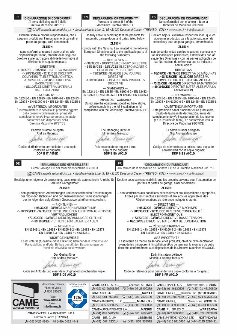
DECLARATION DU FABRICANTAux termes de la disposition de l’Annexe II B de la Directive Machines 98/37/CE
Déclare sous sa responsabilité, que les produits suivants pour l’automation deportails et portes de garage, ainsi dénommés:
ZL150N... sont conformes aux conditions nécessaires et aux dispositions appropriées,
fi xées par les Directives suivantes et aux articles applicables desRèglementations de référence indiqués ci-après.
--- DIRECTIVES ----> 98/37/CE - 98/79/CE DIRECTIVE MACHINES
-> 98/336/CEE - 92/31/CEE DIRECTIVE COMPATIBILITÉELECTROMAGNÉTIQUE
-> 73/23/CEE - 93/68/CE DIRECTIVE BASSE TENSION-> 89/106/CEE DIRECTIVE MATÉRIAUX DE CONSTRUCTION
--- RÈGLEMENTATIONS ---EN 13241-1 • EN 12635 • EN 6100-6-2 • EN 12453 • EN 12978
EN 61000-6-3 • EN 12445 • EN 60335-1AVIS IMPORTANT !
Il est interdit de mettre en service le/les produit/s, objet de cette déclaration,avant de les incorporer à l’installation et/ou de terminer le montage de cettedernière, conformément aux dispositions de la Directive Machines 98/37/CE.
L’administrateur déléguéMonsieur Andrea Menuzzo
Code de référence pour demander une copie conforme à l’original :DDF B FR A001D
ERKLÄRUNG DES HERSTELLERSGemäß Anlage II B der Maschinenrichtlinie 98/37/EU
Bestätigt unter eigener Verantwortung, dass folgende automatische Antriebe fürTore und Garagentore:
ZL150N… den grundlegenden Anforderungen und entsprechenden Bestimmungen
der folgenden Richtlinien und der anzuwendenden Teilbestimmungender im folgenden aufgeführten Gesetzesvorschriften entsprechen.
--- RICHTLINIEN ----> 98/37/CE - 98/79/CE MASCHINENRICHTLINIE
-> 98/336/CEE - 92/31/CEE RICHTLINIE ÜBER ELEKTROMAGNETISCHEVERTRÄGLICHKEIT
->73/23/CEE - 93/68/CE NIEDERSPANNUNGSRICHTLINIE-> 89/106/CEE RICHTLINIE FÜR BAUMATERIALIEN
--- NORMEN ---EN 13241-1 • EN 12635 • EN 6100-6-2 • EN 12453 • EN 12978
EN 61000-6-3 • EN 12445 • EN 60335-1WICHTIGE HINWEISE!
Es ist untersagt, das/die diese Erklärung betreffende/n Produkt/e vorFertigstellung und/oder Einbau gemäß den Bestimmungen der
Richtlinie 98/37/EU zu verwenden.
Der GeshaftfürerHerr Andrea Menuzzo
Code zur Anforderung einer dem Original entsprechenden Kopie:DDF B DE A001D
DE FR
CAME cancelli automatici s.p.a. • Via Martiri della Libertà, 15 • 31030 Dosson di Casier • TREVISO - ITALY • www.came.it • [email protected]
IT DICHIARAZIONE DI CONFORMITÀAi sensi dell’allegato II B dellaDirettiva Macchine 98/37/CE
Dichiara sotto la propria responsabilità, che iseguenti prodotti per l’automazione di cancelli e
porte da garage, così denominati:
ZL150Nsono conformi ai requisiti essenziali ed alle
disposizioni pertinenti, stabilite dalle seguentiDirettive e alle parti applicabili delle Normative di
riferimento in seguito elencate:
--- DIRETTIVE ----> 98/37/CE - 98/79/CE DIRETTIVA MACCHINE
-> 98/336/CEE - 92/31/CEE DIRETTIVACOMPATIBILITÀ ELETTROMAGNETICA
-> 73/23/CEE - 93/68/CE DIRETTIVABASSA TENSIONE
-> 89/106/CEE DIRETTIVA MATERIALIDA COSTRUZIONE
--- NORMATIVE ---EN 13241-1 • EN 12635 • EN 6100-6-2 • EN 12453 •EN 12978 • EN 61000-6-3 • EN 12445 • EN 60335-1
AVVERTENZA IMPORTANTE!È vietato mettere in servizio il/i prodotto/i oggetto
della presente dichiarazione, prima delcompletamento e/o incorporamento, in totale
conformità alle disposizioni dellaDirettiva Macchine 98/37/CE
L’amministratore delegatoAndrea Menuzzo
Codice di riferimento per richiedere una copiaconforme all’originale:
DDF B IT A001D
DECLARATION OF CONFORMITYPursuant to annex II B of the
Machinery Directive 98/37/EC
Is fully liable in declaring that the products forautomatic garage doors and gates listed below:
ZL150Ncomply with the National Law related to the followingEuropean Directives and to the applicable parts of
the following Standards:
— DIRECTIVES —-> 98/37/CE - 98/79/CE MACHINERY DIRECTIVE-> 98/336/CEE - 92/31/CEE ELECTROMAGNETIC
COMPATIBILITY DIRECTIVE-> 73/23/CEE - 93/68/CE LOW VOLTAGE
DIRECTIVE-> 89/106/CEE CONSTRUCTION PRODUCTS
DIRECTIVE
--- STANDARDS ---EN 13241-1 • EN 12635 • EN 6100-6-2 • EN 12453 •EN 12978 • EN 61000-6-3 • EN 12445 • EN 60335-1
IMPORTANT WARNING!Do not use the equipment specifi ed here above,
before completing the full installation In fullcompliance with the Machinery Directive 98/37/EC
The Managing DirectorMr. Andrea Menuzzo
Reference code to request a truecopy of the original:DDF B EN A001D
DECLARACIÓN DE CONFORMIDADDe conformidad con el anexo II B de la
Directiva de Máquinas 98/37/CE
Declara bajo su exclusiva responsabilidad, que lossiguientes productos para la automatización decancelas y puertas para garajes, denominados:
ZL150Nson de conformidad con los requisitos esenciales ylas disposiciones pertinentes, establecidos por lassiguientes Directivas y con las partes aplicables de
las Normativas de referencia que se indican acontinuación:
--- DIRECTIVAS ----> 98/37/CE - 98/79/CE DIRECTIVA DE MÁQUINAS
-> 98/336/CEE - 92/31/CEE DIRECTIVACOMPATIBILIDAD ELECTROMAGNÉTICA
-> 73/23/CEE - 93/68/CE DIRECTIVA BAJA TENSIÓN-> 89/106/CEE DIRECTIVA MATERIALES PARA LA
FABRICACIÓN
--- NORMATIVAS ---EN 13241-1 • EN 12635 • EN 6100-6-2 • EN 12453 •EN 12978 • EN 61000-6-3 • EN 12445 • EN 60335-1
ADVERTENCIA IMPORTANTE!Está prohibido hacer funcionar el/los producto/s,
objeto de la presente declaración, antes delcompletamiento y/o incorporación de los mismos(en la instalación fi nal), de conformidad con la
Directiva de Máquinas 98/37/CE
El administrador delegado:Sig. Andrea Menuzzo
Código de referencia para solicitar una copia deconformidad con la copia original:
DDF B ES A001D
CAME cancelli automatici s.p.a. • Via Martiri della Libertà, 15 • 31030 Dosson di Casier • TREVISO - ITALY • www.came.it • [email protected]
EN ES