SERIE Z | Z SÉRIE Z | SERIE Z QUADRO COMANDO S77 … · - Lampada spia per segnalazione "cancello...
22
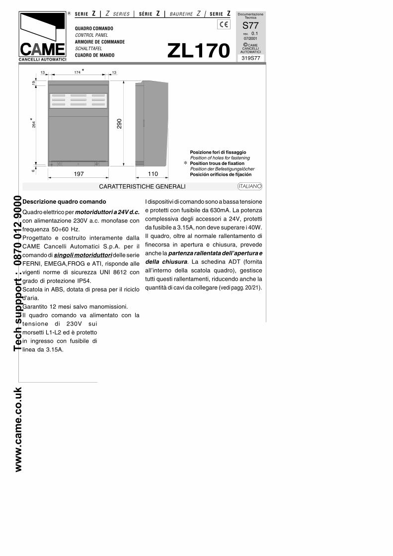
www.came.co.uk Tech suppport : 0870 012 9000 Documentazione Tecnica S77 rev. 0.1 07/2001 © CAME CANCELLI AUTOMATICI 319S77 QUADRO COMANDO CONTROL PANEL ARMOIRE DE COMMANDE SCHALTTAFEL CUADRO DE MANDO SERIE Z | Z SERIES | SÉRIE Z | BAUREIHE Z | SERIE Z ZL170 CANCELLI AUTOMATICI CARATTERISTICHE GENERALI ITALIANO Descrizione quadro comando Quadro elettrico per motoriduttori a 24V d.c. con alimentazione 230V a.c. monofase con frequenza 50÷60 Hz. Progettato e costruito interamente dalla CAME Cancelli Automatici S.p.A. per il comando di singoli motoriduttori delle serie FERNI, EMEGA,FROG e ATI, risponde alle vigenti norme di sicurezza UNI 8612 con grado di protezione IP54. Scatola in ABS, dotata di presa per il riciclo d'aria. Garantito 12 mesi salvo manomissioni. Il quadro comando va alimentato con la tensione di 230V sui morsetti L1-L2 ed è protetto in ingresso con fusibile di linea da 3.15A. I dispositivi di comando sono a bassa tensione e protetti con fusibile da 630mA. La potenza complessiva degli accessori a 24V, protetti da fusibile a 3.15A, non deve superare i 40W. Il quadro, oltre al normale rallentamento di finecorsa in apertura e chiusura, prevede anche la partenza rallentata dell’apertura e della chiusura. La schedina ADT (fornita all’interno della scatola quadro), gestisce tutti questi rallentamenti, riducendo anche la quantità di cavi da collegare (vedi pagg. 20/21). 197 110 290 174 * 264 * 13 13 19 6 Posizione fori di fissaggio Position of holes for fastening Position trous de fixation Position der Befestigungslöcher Posición orificios de fijación *
Transcript of SERIE Z | Z SÉRIE Z | SERIE Z QUADRO COMANDO S77 … · - Lampada spia per segnalazione "cancello...
ww
w.c
am
e.c
o.u
k
T
ec
h s
up
pp
ort
:
08
70
01
2 9
00
0Documentazione
Tecnica
S77rev. 0.107/2001
© CAMECANCELLI
AUTOMATICI
319S77
QUADRO COMANDOCONTROL PANELARMOIRE DE COMMANDESCHALTTAFELCUADRO DE MANDO
SERIE Z | Z SERIES | SÉRIE Z | BAUREIHE Z | SERIE Z
ZL170CANCELLI AUTOMATICI
CARATTERISTICHE GENERALI ��������
Descrizione quadro comando
Quadro elettrico per motoriduttori a 24V d.c.con alimentazione 230V a.c. monofase con
frequenza 50÷60 Hz.Progettato e costruito interamente dallaCAME Cancelli Automatici S.p.A. per il
comando di singoli motoriduttori delle serieFERNI, EMEGA,FROG e ATI, risponde allevigenti norme di sicurezza UNI 8612 con
grado di protezione IP54.Scatola in ABS, dotata di presa per il riciclod'aria.
Garantito 12 mesi salvo manomissioni.Il quadro comando va alimentato con latensione di 230V sui
morsetti L1-L2 ed è protettoin ingresso con fusibile dilinea da 3.15A.
I dispositivi di comando sono a bassa tensionee protetti con fusibile da 630mA. La potenza
complessiva degli accessori a 24V, protettida fusibile a 3.15A, non deve superare i 40W.Il quadro, oltre al normale rallentamento di
finecorsa in apertura e chiusura, prevedeanche la partenza rallentata dell’apertura edella chiusura. La schedina ADT (fornita
all’interno della scatola quadro), gestiscetutti questi rallentamenti, riducendo anche laquantità di cavi da collegare (vedi pagg. 20/21).
197 110
290
174 *
264 *
13 13
196
Posizione fori di fissaggioPosition of holes for fasteningPosition trous de fixationPosition der BefestigungslöcherPosición orificios de fijación
*
ww
w.c
am
e.c
o.u
k
T
ec
h s
up
pp
ort
:
08
70
01
2 9
00
0
-2-
Sicurezza
Le fotocellule possono essere collegate e
predisposte per:- Riapertura in fase di chiusura (2-C1), lefotocellule rilevando un ostacolo durante la
fase di chiusura del cancello, provocanol’inversione di marcia fino alla completaapertura;
- Stop parziale (2-C3), arresto del cancello sein movimento con conseguentepredisposizione alla chiusura automatica;
- Stop totale (1-2), arresto del cancello conl'esclusione del ciclo di chiusura automatica;per riprendere il movimento bisogna agire
sulla pulsantiera o sul radiocomando.
- Il quadro elettrico include un sensoreamperometrico del motore che intervienequando un ostacolo blocca il movimento inapertura o in chiusura. Se in marcia, esso
inverte il movimento. Se in rallentamento, ilmotore si blocca. La sensibilità del dispositivoè regolabile mediante trimmers (pag. 19).
- Il trasformatore è dotato di una protezioneche in caso di sovraccarico termico mantiene
l’anta aperta. La richiusura avviene solo dopoche la temperatura è scesa sotto la soglia diemergenza.
Accessori collegabili
- Lampada spia per segnalazione "cancelloaperto" (10-5);- Lampada ciclo per illuminare la zona di
manovra: rimane accesa dal momento in cuile ante iniziano l'apertura fino alla completachiusura (compreso il tempo di chiusura
automatica). Nel caso non venga inserita lachiusura automatica, rimane accesa solodurante il movimento.
Collegarla sui morsetti 10-E3 e selezionarlatramite jumper. E’ alternativa al 2° canale
radio (vedi pag. 16);- Lampeggiatore di movimento, conpossibilità di selezionare il prelampeggiodello stesso (dip 4 selettore funzioni);- Elettroserratura;- Scheda LB18 per alimentazione mediante
batterie che, in caso di mancanza di energiaelettrica, interviene automaticamente. Alripristino della tensione di linea, provvede
alla ricarica delle batterie stesse;- Scheda radiofrequenza AF, (vedi tabellapag. 23);
Inoltre è previsto un contatto ausiliario, suimorsetti A1-A2, per qualsiasi dispositivo da
attivare contemporaneamente al comandodi apertura.
Altre funzioni selezionabili
- Chiusura automatica. Il temporizzatore dichiusura automatica si autoalimenta a fine-tempo corsa in apertura. Il tempo prefissato
regolabile, è comunque subordinatodall'intervento di eventuali accessori disicurezza e si esclude dopo un intervento di
"stop" o in mancanza di energia elettrica;- Rilevazione ostacolo. A motore fermo(cancello chiuso, aperto o dopo un comando
di stop totale), impedisce qualsiasimovimento se i dispositivi di sicurezza (es.fotocellule) rilevano un ostacolo;
- Colpo d'ariete. Funzione che facilita losganciamento della serratura; a ognicomando di apertura, le ante premono in
battuta di chiusura per un secondo, facilitandol'operazione di sgancio dell'elettroserratura;- Funzione a "uomo presente".
Funzionamento del cancello mantenendo
ww
w.c
am
e.c
o.u
k
T
ec
h s
up
pp
ort
:
08
70
01
2 9
00
0
-3-
Attenzione! Prima di intervenire
all’interno dell’apparecchiatura, toglierela tensione di linea e scollegare lebatterie (se inserite).
premuto il pulsante (esclude la funzione delradiocomando);- Selezione motoriduttore da comandare,
tramite selettore funzioni;- Selezione tipo di comando:
- «apre-stop-chiude-stop» per pulsante
e/o trasmettitore;- «apre-chiude-inversione» per pulsante
e/o trasmettitore;
- «solo apre» per trasmettitore.
Regolazioni
- Trimmer SENS/VEL = Regolazionesensibilità amperometrica durante la marcia:
min/max;- Trimmer SENS/RALL = Regolazionesensibil ità amperometrica durante il
rallentamento: min/max;- Trimmer TCA = Regolazione tempo chiusuraautomatica: da 1" a 120";
- Trimmer TL = Regolazione tempo di lavoro:da 13" a 120";- Regolazione velocità di marcia e dirallentamento mediante connettori faston sultrasformatore.
ww
w.c
am
e.c
o.u
k
T
ec
h s
up
pp
ort
:
08
70
01
2 9
00
0
-4-
GENERAL CHARACTERISTICS �����
Description of control panel
Control panel for 24V d.c. gear motors,
powered by 230V a.c. at 50-60 Hz (single-phase).Designed to control single FERNI, EMEGA,
FROG and ATI gear motors.Designed and built entirely by CAMECANCELLI AUTOMATICI S.p.A. to meet UNI
8612 safety standards at an IP 54 protectionlevel.Housing in ABS is equipped with vents to
provide internal air circulation.Guaranteed 12 months, unless tamperedwith.
This control panel is powered by 230V a.c.across terminals L1 and L2, and is protectedby a 3.15A fuse on the main power line.
Control systems are powered by low voltageand protected by a 630mA fuse.The total power consumption of 24V
accessories (which are protected by a 3.15Afuse) must not exceed 40 W.In addition to normal endstop slowing when
closing and opening, the control panel alsoallows slowed-down initial opening andclosing movements. The ADT card (supplied
in the control panel box) manages theseslower movements, also decreasing theamount of connection cables (see pages 20/
21).
Safety
Photocells can be connected to obtain:- Re-opening during the closing cycle (2-
C1), if the photocells identify an obstaclewhile the gate is closing, they will reversethe direction of movement until the gate is
completely open;
- Partial stop, shutdown of moving gate, with
activation of an automatic closing cycle (2-C3);- Total stop (1-2), shutdown of gate movement
without automatic closing; a pushbutton orradio remote control must be actuated toresume movement).
- The electrical panel includes anamperometric sensor for the motor which is
triggered whenever an obstacle blocksmovement during opening or closing. Ifoperating speed, the sensor inverts the
movement direction. If it is slowing down, themotor stops. The sensor's sensitivity can beadjusted using the trimmers.
- The transformers are equipped with a guardthat will keep the doors open in case ofthermal overload. They are closed again only
after the temperature falls below theemergency threshold.
Accessories which can be connected tothis unit
- “Gate open” signal light (10-5);- Cycle lamp to light the passage area: it
remains on from the moment the doors beginto open until they are fully closed (includingthe automatic closing time). If automatic
closing is not activated, the lamp remains ononly during movement.Connect it to terminals 10-E3 and select it
with a jumper. It is an alternative to thesecond radio channel (see page 16);- Movement flashing lamp with pre-flashingoption (dip 4 function selector);- Electric lock;
ww
w.c
am
e.c
o.u
k
T
ec
h s
up
pp
ort
:
08
70
01
2 9
00
0
-5-
- LB18 circuit card for battery operation,which is automatically connected in case ofpower failure. Battery is recharged when line
voltage is restored.- Radiofrequency AF board (see table pag.23).
An auxiliary contact is also provided onterminals A1-A2 for any device that should be
activated at the same time as the openingcommand.
Other functions available
- Automatic closing. The automatic closing
timer is automatically activated at the end ofthe opening cycle. The preset, adjustableautomatic closing time is automatically
interrupted by the activation of any safetysystem, and is deactivated after a STOPcommand or in case of power failure;
- Obstacle detection. When the motor isstopped (gate is closed, open or half-openafter an emergency stop command), the
transmitter and the control pushbutton willbe deactivated if an obstacle is detected byone of the safety devices (for example, the
photocells);- Hammer movement. This feature makes iteasy for the lock to release (the door wings
momentarily press against the closure stopswhen the open command is given, whichfacilitates release of the electric lock);
- "Operator present" function. Gate operatesonly when the pushbutton is held down (theradio remote control system is deactivated);
- Gear motor selection to be operated via afunction selector;- Type of command:
- «open-stop-close-stop» for pushbutton
and radio transmitter;- «open-close-reverse» for pushbutton
and radio transmitter;
- «open only» for radio transmitter.
Adjustments
- Trimmer SENS/VEL = Adjustment ofamperometric sensitivity during operating:
min/max;- Trimmer SENS/RALL = Adjustment ofamperometric sensitivity during slowdown:
min/max;- Trimmer TCA = Adjustment of automaticclosing time: 1" to 120";
- Trimmer TL = Adjustment of operating time:13" to 120";- Faston connectors on the transformer are
used to select normal operating andslowdown speeds;
Caution! Shut off the mains power
and disconnect the batteries beforeservicing the inside of the unit.
ww
w.c
am
e.c
o.u
k
T
ec
h s
up
pp
ort
:
08
70
01
2 9
00
0
-6-
Description armoire de commande
Armoire électrique pour motoréducteurs à24V c.c. avec alimentation 230Vmonophasée; fréquence 50÷60 Hz.
Entièrement conçue et fabriquée par CAMECancelli Automatici S.p.A. pour commanderles différents motoréducteurs de la série
FERNI, EMEGA, FROG et ATI, l'armoire estconforme aux normes de sécurité en vigueurUNI 8612 avec un degré de protection IP
54.Boîtier en ABS muni de prise de circulationd’air. Garantie 12 mois sauf en cas
d’endommagement.L’armoire de commande doit être alimentéeavec une tension de 230V sur les bornes L1
et L2 et elle est protégée en entrée par unfusible de ligne de 3.15A. Les dispositifs decommande sont à basse tension et protégés
avec un fusible de 630mA. La puissancetotale des accessoires en 24V, protégés parun fusible de 3.15A, ne doit pas dépasser
40W.Mis à part le ralentissement normal de fin decourse en ouverture et en fermeture,
l'armoire prévoit également le départ ralentide l'ouverture et de la fermeture. La carteADT (fournie à l'intérieur de l'armoire) gère
tous ces ralentissements, en réduisantégalement la quantité de câbles à brancher(voir pages 20/21).
Sécurité
Il est possible de brancher des photocelluleset de les programmer pour:
- Réouverture en phase de fermeture (2-C1),les cellules photoélectriques provoquentl’inversion de marche jusqu’à l’ouverture
complète si elles relèvent un obstacle durant
la phase de fermeture du portail;- Stop partiel (2-C3), arrêt du portail etfermeture automatique;
- Stop total (1-2), arrêt du portail etdésactivation d’un éventuel cycle defermeture automatique; pour activer de
nouveau le mouvement, il faut agir sur lesboutons-poussoirs ou sur laradiocommande);
- Le tableau électrique contient un capteurampèremétrique du moteur qui
intervient quand un obstacle bloque lemouvement durant la phase d’ouvertureou de fermeture.
Le capteur inverse le mouvement lorsquecela se produit. S’il s’agit de laphase de ralentissement, le moteur
concerné se bloque alors que l’autrecomplète le mouvement.Des compensateurs permettent de régler la
sensibilitédu dispositif (page 19).- Le transformateur est équipé d'une
protection qui permet au vantail de resterouvert en cas de surcharge thermique.Celui-ci ne peut se refermer que quand la
température est descendue en dessous duseuil d'urgence.
Accessoires pouvant être branchés
- Lampe pour signalisation de “portail ouvert”(10-5);- Lampe cycle pour éclairer la zone de
manœuvre: elle reste allumée à partir dumoment où les vantaux commencent às'ouvrir jusqu'à la fermeture complète (y
compris le temps de fermeture automatique).Elle ne reste allumée que durant le
CARACTÉRISTIQUES GÉNÉRALES ���� ��
ww
w.c
am
e.c
o.u
k
T
ec
h s
up
pp
ort
:
08
70
01
2 9
00
0
-7-
mouvement si la fermeture automatique n'est
pas activée.La brancher aux bornes 10-E3 et lasélectionner à l'aide du cavalier. Elle peut
être utilisée à la place du 2ème canal radio(voir page 16);- Clignotant indiquant le mouvement, avec
possibil ité d'en sélectionner le pré-clignotement (interrupteur 4 sélecteur defonctions);
- Serrure électrique;- Carte LB18 pour l'alimentation par batteriesqui intervient automatiquement en cas de
coupure de courant. Elle recharge lesbatteries quand le courant est rétabli;- Carte radiofréquence AF (voir tableau pag.
23);
Un contact auxiliaire est également prévu,
sur les bornes A1-A2, pour n'importe queldispositif à activer en même temps que lacommande d'ouverture.
Autres fonctions pouvantêtre sélectionnées
- Fermeture automatique. Le temporisateurde fermeture automatique est autoalimentéà la fin du temps de la course en ouverture.
Le temps réglable est programmé,cependant, il est subordonné à l’interventiond’éventuels accessoires de sécurité et il est
exclu après une intervention de “stop” ou encas de coupure de courant;- Détection obstacle. Quand le moteur est
arrêté (portail fermé, ouvert ou semi-ouvert,cette position est obtenue avec unecommande de stop total), annule toute
fonction de l’émetteur ou du bouton-poussoiren cas d’obstacle détecté par les dispositifsde sécurité (ex. Photocellules) ;
- Coup de bélier. Fonction qui facilite le
déblocage de la serrure (à chaque
commande d’ouverture, les vantaux seportent en butée de fermeture pendant uneseconde, facilitant ainsi l’opération de
déblocage de la serrure électrique);- Fonction “homme mort”. Fonctionnementdu portail en maintenant appuyé le bouton-
poussoir (exclut la fonction de laradiocommande);- Sélection du motoréducteur à commander
à l'aide du sélecteur de fonctions;- Type de commande:
- «ouverte-stop-fermée-stop» pour
bouton-poussoir et émetteur radio;- «ouverture - fermeture - inversion» pour
bouton-poussoir et émetteur radio;
- «seulement ouverture» pour émetteurradio.
Réglages
- Trimmer SENS/VEL = Réglage sensibilitéampèrométrique pendant le mouvement :
min./max;- Trimmer SENS/RALL = Réglage sensibilitéampèrométrique pendant le ralentissement
: min./max;- Trimmer T.C.A. = Temps de fermetureautomatique: de 1 à 120";
- Trimmer T.L. = Réglage temps defonctionnement: de 13" à 120";- Réglage vitesse de mouvement et deralentissement à l'aide de connecteursrapides placés sur le transformateur.
Attention! Avant d’intervenir à
l’intérieur de l’appareillage, couper latension de ligne et débrancher lesbatteries (si branchées).
ww
w.c
am
e.c
o.u
k
T
ec
h s
up
pp
ort
:
08
70
01
2 9
00
0
-8-
ALLGEMEINE MERKMALE �����
Beschreibung des Steuergeräts
Schalttafel für 24-V-Gleichstrom-Getriebemotoren mit 230-V-
Einphasenstromversorgung; Frequenz:50-60 Hz.Vollkommen von der CAME Cancelli
Automatici S.p.A. zur Steuerung voneinzelnen Getriebemotoren der SerieFERNI, EMEGA, FROG und ATI
entsprechend den geltendenSicherheitsnormen UNI 8612 mit SchutzgradIP54 entwickelt und hergestellt.
ABS-Gehäuse mit Luftklappe. 12 MonateGarantie, vorbehaltlich unsachgemäßerHandhabung und Montage.
Die Schalttafel wird mit einer Spannung von230V über die Klemmen L1 und L2 gespeistund ist am Eingang mit einer 3.15-A-
Hauptsicherung. Die Steuerungen erfolgenmit Niederspannung und geschützen enie630mA-Sicherung. Die Gesamtleistung des
durch eine 3.15-A-Sicherung geschützten24-V-Zubehörs darf 40W nichtüberschreiten.
Auf der Schalttafel ist außer dem normalenBremsvermögen des Anschlags auch derverlangsamte Öffnungs- undSchließungsbeginn vorgesehen. Die ADT-Karte (im Inneren des Schalttafelgehäuses)verwaltet alle diese Verlangsamungen , bei
gleichzeitiger Verminderung der Anzahlanzuschließender Kabel. (siehe Seiten 20/21)
Sicherheitsvorrichtungen
Die Lichtschranken können für folgendeFunktionen angeschlossen bzw. vorbereitetwerden:
- Wiederöffnen beim Schließen (2-C1), die
Lichtschranken ermitteln ein Hinderniswährend des schließens vom Tor und lösen
die Umkehr der Laufrichtung vom Tor aus,bis dieses wieder vollständig geöffnet ist;- Teilstop (2-C3), Stillstand des Tores
während des Torlaufs, mit darauffolgenderautomatischer Torschließung;- Totalstop (1-2), sofortiger Stillstand des
Tores mit Ausschluß eventuellerSchließautomatik: Fortsetzung des Torlaufsüber Drucktaster- bzw.
Funksendersteuerung;
- Auf der Schalttafel befindet sich ebenfalls
ein Motor-Stromsensor, welcher eingreift,wenn die Bewegung beim Öffnen undSchließen durch ein Hindernis blockiert wird.
Bei Normallauf wird die Bewegung somitumgesteuert. Beim Bremsen wird ein Motorblockiert, während der andere seineBewegung vollendet.
Die Empfindlichkeit der Vorrichtung ist durchTrimmer einstellbar (seite. 19).- Der Transformator Ist mit einer Sicherungausgestattet, die bei Wärmestau dafür sorgt,daß der Türflügel offen bleibt.Das erneute Schließen erfolgt erst dann,
wenn die Temperatur unter den Wert, derdie Notsituation auslöst hat, gefallen ist..
Anschließbares Zubehör
- Anzeigeleuchte für “Tor offen” (10-5);- Lampe zur Beleuchtung derSteuerungszone: bleibt vom Beginn der
Öffnung der Türflügel bis zum vollständigenSchließen (einschließlich die Zeit für dasautomatische Schließen) eingeschaltet.
Ohne Aktivierung der automatischenSchließung, bleibt sie nur während der
ww
w.c
am
e.c
o.u
k
T
ec
h s
up
pp
ort
:
08
70
01
2 9
00
0
-9-
Bewegung eingeschaltet.An den Klemmen 10-E3 anschließen und
mittels Funktionswählschalter wählen.Alternativ zum 2° Radiokanal (siehe Seite16)
- Bewegungsblinker mit der Wahlmöglichkeitvon vorherigem Blinken (dip 4
Funktionswählschalter);- Elektroschloß;- Karte LB18 für Stromversorgung über
Notbatterien, die sich bei Stromausfallautomatisch zuschalten. Bei erneuterNetzstromversorgung lädt dieselbe die
Batterien erneut aut.- Funkfrequenz-Platine AF (siehe TabelleSeite 23);
Es ist ferner ein Zusatzkontakt auf denKlemmen A1-A2 für jede beliebige
Vorrichtung, die gleichzeitig mit derÖffnungssteuerung zu aktivieren ist,vorgesehen.
Andere Wahlfunktionen
- Schließautomatik. Der Schließautomatik-Zeischalter speist sich beim Öffnen am Endeder Torlaufzeit selbst . Die voreingestellte Zeit
ist auf jeden Fall immer dem Eingriffeventueller Sicherheitsvorrichtungenuntergeordnet und schließt sich nach einem
“Stop”-Eingriff bzw. bei Stromausfall selbstaus;- Hinderniserfassung. Bei stillstehendem
Motor (Tor geschlossen, geöffnet oder durcheine Totalstop-Steuerung halb geöffnet) wirdbei durch die Sicherheitsvorrichtungen (z.B.:
Lichtschranken) erfaßtem Hindernis jedeSender- oder Drucktasterfunktion annulliert;- Widderstoß. Funktion, die das Auslösen des
Elektroschlosses erleichtert; (bei jeder
Öffnungssteuerung üben die Torflügel eineSekunde lang einen leichten Druck auf denSchließungsendanschlag aus und
erleichtern dadurch die Entriegelung desElektroschlosses);- Funktion “Bedienung vom Steuerpult”.Torbetr ieb durch Drucktasterbetätigung(Funkfernsteuerung ausgeschlossen);- Wahl Getriebemotor durch
Funktionswählschalter;- Steuerart:
- «Öffnen-Stop-Schließen-Stop» für
Drucktaster- und Funksendersteuerart;- « Ö f f n e n - S c h l i e ß e n -
Torlaufumsteuerung» für Drucktaster
und Funksendersteuerart;- «nur Öffnen» für Funksendersteuerart.
Einstellungen
- Trimmer SENS/VEL = Einstellung deramperemetrischen Empfindlichk eitwährend Laufgeschwindigkeit: min/max;
- Trimmer SENS/RALL = Einstellung deramperemetrischen Empfindlichk währendLaufverlangsamung: min/max;
- Tr immer TCA = ZeiteinstellungSchließautomatik: von 1" bis 120",- Trimmer TL = Einstellung Laufzeit: von 13"
bis 120";- Einstellung der Laufgeschwindigkeit undder Laufver langsamung über Faston-
Verbinder am Transformator.
Achtung! Das Gerät vor Eingriffen
im inneren spannungsfrei schalten unddie Stromzufuhr mittels Batterien (fallszugeschaltet) unterbrechen.
ww
w.c
am
e.c
o.u
k
T
ec
h s
up
pp
ort
:
08
70
01
2 9
00
0
-10-
CARACTERISTICAS GENERALES ������
Descripción cuadro de mando
Cuadro eléctrico para motorreductores a24V d.c. con alimentación 230V monofase:frecuencia 50÷60 Hz.Diseñado y fabricado enteramente por
CAME CANCELLI AUTOMATICI S.p.A. parael accionamiento de motorreductoresindependientes serie FERNI, EMEGA,
FROG y ATI, cumple con las normas deseguridad vigentes UNI 8612, con grado deprotección IP 54.
Caja de ABS, dotada de toma para larecirculación de aire. Garantizado 12 mesessalvo manipulaciones.
El cuadro de mando se alimenta con unatensión de 230V en los bornes L1 y L2 yestá protegido en entrada con fusible de
línea de 3.15A. Los dispositivos de mandoson a baja tensión y està protegidos porfusible a 630mA. La potencia total de los
accesorios a 24V, protegidos por fusible a3.15A, no debe superar los 40W.Además de la deceleración normal en fin
de carrera en apertura y cierre, el cuadrotambién prevé el arranque lento de laapertura y del cierre. La tarjeta ADT
(suministrada dentro de la caja del cuadro),gestiona todas las deceleraciones,reduciendo la cantidad de cables que se
han de conectar (véanse págs. 20/21).
Seguridad
Las fotocélulas pueden estar conectadas ypredispuestas para:- Reapertura en la fase de cierre (2-C1), las
fotocélulas detectan un obstàculo duranteel cierre de la puerta, provocando lainversión de marcha hasta la apertura
completa;
- Parada parcial (2-C3), parada de la puertasi se encuentra en movimiento con laconsiguiente predisposición al cierre
automático;- Parada total (1-2), parada de la puertaexcluyendo el posible ciclo de cierre
automático; para reactivar el movimiento espreciso actuar en el teclado o en el mando adistancia);
- El cuadro eléctrico incluye un sensoramperimétrico del motor que se activa
cuando un obstáculo bloquea el movimientodurante la apertura o cierre. Si el motor estáfuncionando, el sensor invierte el
movimiento. Si un motor estádesacelerando, éste se detiene, mientrasque el otro motor completa su movimiento.
La sensibilidad del dispositivo se ajusta conlos trimmers (pág.19).- El transformador está equipado con una
protección que ante una sobrecarga térmicamantiene abiertas las hojas.El cierre se produce sólo después de que la
temperatura ha descendido por debajo delumbral de emergencia.
Accesorios conectables
- Lámpara por señal de “puerta abierta” (10-
5);- Lámpara ciclo para iluminar la zona demaniobra: queda encendida desde cuando
las hojas comienzan a abrirse hasta que secierran por completo (incluido el tiempo decierre automático). Si no se conectara el
cierre automático, queda encendida sólodurante el movimiento.
ww
w.c
am
e.c
o.u
k
T
ec
h s
up
pp
ort
:
08
70
01
2 9
00
0
-11-
Conéctela a los bornes 10-E3 y selecciónelacon el jumper. Es alternativa al 2° canal radio
(véase pág. 16);-Luz intermitente de movimiento conposibilidad de seleccionar la intermitenciaprevia (dip 4 selector funciones);
- Cerradura eléctrica;
- Tarjeta LB18 para la alimentaciónmediante baterías que, en caso de falta deenergía eléctrica, interviene
automáticamente. Una vez conectada denuevo la tensión de línea, se ocupa decargar las baterías;
- Tarjeta radiofrecuencia AF (ver tablapág.23);
También se ha previsto un contacto auxiliar,en los bornes A1-A2, para cualquier
dispositivo que se haya de activarsimultáneamente al mando de apertura.
Otras funciones seleccionables
- Cierre automático. El temporizador decierre automático se autoalimenta en fin-de-
tiempo carrera en fase de apertura. El tiempoprefijado regulable, sin embargo, estásubordinado a la intervención de posibles
accesorios de seguridad y se excluyedespués de una intervención de parada oen caso de falta de energía eléctrica;
- Detección obstáculo. Con el motor parado(puerta cerrada, abierta o en posición semi-abierta obtenida a través de un comando
de stop total), anula cualquier función deltransmisor o del botón en caso de obstáculodetectado por los dispositivos de seguridad
(por ejemplo: fotocélulas);
- Golpe de ariete. Función que facilita el
desenganche de la cerradura (en cadacomando de apertura las puertas presionanel tope del cierre durante un segundo,
facilitando la operación de desenganche dela electrocerradura);- Función a "hombre presente".
Funcionamiento de la puerta manteniendopulsada la tecla (excluye la función delmando a distancia);
-Selección del motorreductor que se ha deaccionar con el selector de funciones;- Tipo de mando;
- «apertura-parada-cierre-parada» paratecla y transmisor de radio;
- «apertura-cierre-inversión» para tecla
y transmisor de radio;- «sólo apertura» para transmisor de
radio.
Regulaciones
- Trimer SENS/VEL = Regulaciónsensibilidad amperimétrica durante lamarcha: mín/máx;
- Trimer SENS/RALL = Regulaciónsensibilidad amperimétrica durante elralentamiento: mín/máx;
- Trimer TCA = Tiempo cierre automático: de1" a 120”;- Trimer TL = Regulación tiempo trabajo: de
13" a 120";- Regulación velocidad de marcha y dedeceleración por medio de conectores faston
en el transformador
¡Atención! Antes de actuar dentro
del aparato, quitar la tensión de línea ydesecnectar las baterías (si estuvieranconectadas).
ww
w.c
am
e.c
o.u
k
T
ec
h s
up
pp
ort
:
08
70
01
2 9
00
0
-12-
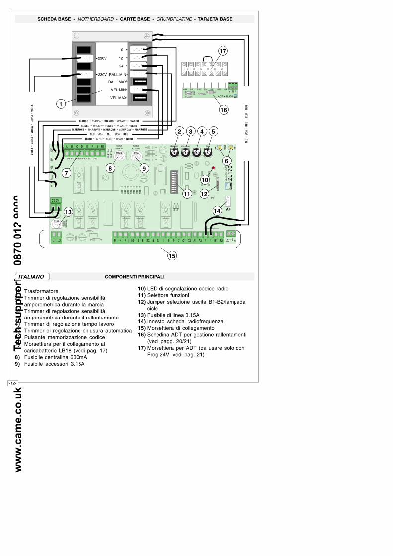
SCHEDA BASE - MOTHERBOARD - CARTE BASE - GRUNDPLATINE - TARJETA BASE
1) Trasformatore2) Trimmer di regolazione sensibilità
amperometrica durante la marcia3) Trimmer di regolazione sensibilità
amperometrica durante il rallentamento4) Trimmer di regolazione tempo lavoro5) Trimmer di regolazione chiusura automatica6) Pulsante memorizzazione codice7) Morsettiera per il collegamento al
caricabatterie LB18 (vedi pag. 17)8) Fusibile centralina 630mA9) Fusibile accessori 3.15A
10) LED di segnalazione codice radio11) Selettore funzioni12) Jumper selezione uscita B1-B2/lampada
ciclo13) Fusibile di linea 3.15A14) Innesto scheda radiofrequenza15) Morsettiera di collegamento16) Schedina ADT per gestione rallentamenti
(vedi pagg. 20/21)17) Morsettiera per ADT (da usare solo con
Frog 24V, vedi pag. 21)
COMPONENTI PRINCIPALIITALIANO
230V
230V
0
12
24
RALL.MIN
RALL.MAX
VEL.MIN
VEL.MAX
AF
ZL1
70������������
����SENS VEL T LSENS RALL T C A� � � � �
��� �������������������
�� � �����
���������
�������
� �����
��� ���
�������
����
� �����
���������
�������2
13
45
67
89
10
��
21
�����
��
���
���
J2
�� �� � � � �� �� � � � � � � �� �� �� � �� ���� �
78 9
32 4 5
10
14
11
13
15
12
�� � �� � � �
� � �
ADT x ZL170
161
NERO - NERO - NERO - NERO - NERO
BLU - BLU - BLU - BLU - BLU
MARRONE - MARRONE - MARRONE - MARRONE - MARRONEROSSO - ROSSO - ROSSO - ROSSO - ROSSO
BIANCO - BIANCO - BIANCO - BIANCO - BIANCO
BLU
-BL
U-
BLU
-BL
U-
BLU
VIO
LA-
VIOL
A-
VIO
LA-
VIOL
A-
VIO
LA
17
6
12
ww
w.c
am
e.c
o.u
k
T
ec
h s
up
pp
ort
:
08
70
01
2 9
00
0
-13-
MAIN COMPONENTES
1) Transformer2) Trimmer for adjustment of amperometric
sensitivity during operation3) Trimmer for adjustment of amperometric
sensitivity during slowdown4) Trimmer for adjustment of operating time5) Trimmer for adjustment of automatic closing6) Button for memorizing code7) Terminal board for connectiong battery
charger LB18 (vedi pag. 16))8) Fuse on central control unit, 630 mA9) Fuse on accessory power line, 3.15A10) Radio code signal LED11) Functions switch12) Jumper which selects output B1-B2/
operating cycle indicador light13) Line fuse, 3.15A14) Radiofrequency board socket15) Terminal block for external connections16) ADT card for slowdown control (see pages
21/21)17) ADT terminal board (to be used only with
Frog 24V. See page 21).
ENGLISH PRINCIPAUX COMPOSANTS
1) Transformateur2) Trimmer de réglage sensibilité
ampèremétrique pendant le mouvement3) Trimmer de réglage sensibilité
ampèremétrique pendant le ralentissement4) Trimmer de réglage temps de
fonctionnement5) Trimmer de réglage fermeture automatique6) Bouton-poussoir mémorisation code7) Plaque à bornes pour le branchement au
chargeur de batteries LB18 (vedi pag. 16)8) Fusible boîtier 630mA9) Fusible accessoires 3.15A10) LED de signalisation code radio11) Selecteur de fonctions12) Pontet sélection sortie B1-B2/lampe cycle13) Fusible de ligne 3.15A14) Branchement carte radiofréquence15) Plaque à bornes de connexion16) Carte ADT pour gérer les ralentissements
(voir pages 20/21)17) Plaque à bornes pour ADT (à n'utiliser
qu'avec Frog 24V, voir page 21)
FRANÇAIS
HAUPTKOMPONENTEN
1) Transformatoren2) Trimmer zur Einstellung amperemetrischen
Empfindlichkeit währendLaufgeschwindigkeit
3) Trimmer zur Einstellung amperemetrischenEmpfindlichkeit währendLaufverlangsamung
4) Trimmer zur Einstellung Laufzeit5) Trimmer zur Einstellung der
Schließautomatik6) Code-Speichertasten7) Klemmleiste für den Anschluß an das
Batterieladegerät LB18 (vedi pag. 16)8) Schaltkastensicherung 630mA9) Zubehör-Sicherung 3.15A10) Anzeige LED-Funkcode11) Wählschalter für Funktionen12) Jumper zur Wahl des Ausgangs B1-B2/
Betriebszyklus Anzeigeleuchte13) Hauptsicherung 3.15A14) Steckanschluß Funkfrequenz-Platine15) AnschlußKlemmenleiste16) Karte ADT zur Verwaltung der
Verlangsamungen (siehe Seiten 20/21)17) Klemmenbrett ADT (nur mit Frog 24V zu
benutzen, siehe Seite 21).
DEUTSCH PRINCIPALES COMPONENTES
1) Transformadores2) Trimer de regulación sensibilidad
amperimétrica durante la marcha3) Trimer de regulación sensibilidad
amperimétrica durante el ralentamiento4) Trimer de regulación tiempo trabajo5) Trimer de regulación tiempo cierre
automático6) Teclas memorización códigos7) Caja de bornes para la conexión del
cargador de batería LB18 (vedi pag. 16)8) Fusible para central 630mA9) Fusible accesorios 3.15A10) LED de señal código radio11) Selector de funciones12) Jumper selección salida B1-B2/lámpara
ciclo13) Fusible de línea 3.15A14) Conexión tarjeta radiofrecuencia15) Caja de bornes para las conexiónes16)Tarjeta ADT para gestión de deceleraciones (véanse págs. 20/21)17)Caja de conexiones para ADT (se usa sólo con Frog 24V, véase pág. 21)
ESPANOL
ww
w.c
am
e.c
o.u
k
T
ec
h s
up
pp
ort
:
08
70
01
2 9
00
0
-14-
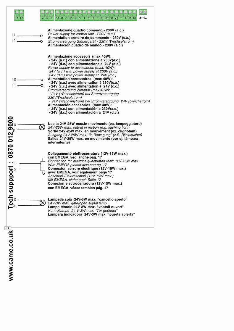
��
��
��
��
��
��
���
���
��
��
Alimentazione quadro comando - 230V (a.c.)Power supply for control unit - 230V (a.c.)Alimentation armoire de commande - 230V (c.a.)Stromversorgung Steuergerät - 230V (Wechselstrom)Alimentación cuadro de mando - 230V (a.c.)
Alimentazione accessori (max 40W): - 24V (a.c.) con alimentazione a 230V(a.c.) - 24V (d.c.) con alimentazione a 24V (d.c.)Power supply to accessories (max. 40W): 24V (a.c.) with power supply at 230V (a.c.) 24V (d.c.) with power supply at 24V (d.c.)Alimentation accessoires (max 40W): - 24V (c.a.) avec alimentation à 230V(c.a.) - 24V (c.c.) avec alimentation à 24V (c.c.)Stromversorgung Zubehör (max 40W): - 24V (Wechselstrom) bei Stromversorgung230V(Wechselstrom) - 24V (Wechselstrom) bei Stromversorgung 24V (Gleichstrom)Alimentación accesorios (max 40W): - 24V (a.c.) con alimentación a 230V(a.c.) - 24V (d.c.) con alimentación a 24V (d.c.)
Uscita 24V-25W max.in movimento (es. lampeggiatore)24V-25W max. output in motion (e.g. flashing light)Sortie 24V-25W max. en mouvement (ex. clignotant)Ausgang 24V-25W max. "in Bewegung" (z.B. Blinkleuchte)Salida 24V-25W max. en movimiento (por ej. lámparaintermitente)
Collegamento elettroserratura (12V-15W max.)con EMEGA, vedi anche pag. 17Connection for electrically-actuated lock: 12V-15W max.With EMEGA please also see pg. 17Connexion serrure électrique (12V-15W max.)avec EMEGA, voir également page 17Anschluß Elektroschloß (12V-15W max.)Mit EMEGA, siehe auch Seite 17Conexión electrocerradura (12V-15W max.)con EMEGA, véase también pág. 17
Lampada spia 24V-3W max. “cancello aperto”24V-3W max. gate-open signal lampLampe-témoin 24V-3W max. "vantail ouvert"Kontrollampe 24 V-3W max. “Tor geöffnet”Lámpara indicadora 24V-3W max. “puerta abierta”
�� �� � � � �� �� � � � � � � �� �� �� � �� ���� �
ww
w.c
am
e.c
o.u
k
T
ec
h s
up
pp
ort
:
08
70
01
2 9
00
0
-15-
1
2
2
7
2
3
2
C1
2
C3
�� �� � � � �� �� � � � � � � �� �� �� � �� ���� �
Collegamento antennaAntenna connectionConnexion antenneAntennenanschlußConexión antena
Pulsante di stop (N.C.)Stop button (N.C.)Bouton-poussoir de stop (N.F.)Stop-Taste (Ruhekontakt)Tecla de parada (N.C.)
Pulsante apre (N.O.)Open button (N.O.)Bouton-poussoir d'ouverture (N.O.)Taste Öffnen (Arbeitskontakt)Tecla de apertura (N.O.)
Collegamento radio e/o pulsante (N.O.)Connector (N.O.) radio and/or pushbuttonConnection radio et/ou bouton-poussoir (N.O.)Anschluß Funkfernsteuerung und/oder Drucktaster (N.O.)Conexión radio y/o pulsador (N.O.)
Contatto (N.C.) di riapertura in fase di chiusura(da cortocircuitare se non viene utilizzato)Contact (N.C.) for re-opening during closure(should be short circuited if not used)Contact (N.F.) de réouverture pendant la fermeture(à court-circuiter s'il n'est pas utilisé)Ruhekontakt Wiederöffnen beim Schließen(bei Nichtbenutzung kurzzuschließen)Contacto (N.C.) para la apertura en la fase de cierre(se cortocircuita si no se utiliza)
Contatto (N.C.) di Stop parzialePartial stop contact (N.C.)Contact (N.F.) d'arrêt partielRuhekontakt Partial-StopContacto (N.C.) de parada parcial
ww
w.c
am
e.c
o.u
k
T
ec
h s
up
pp
ort
:
08
70
01
2 9
00
0
-16-
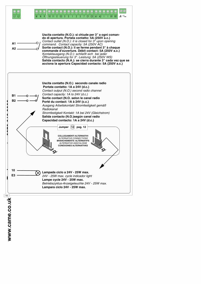
Uscita contatto (N.O.): si chiude per 3” a ogni coman-do di apertura. Portata contatto: 5A (250V a.c.)Contact outlet (N.O.): it is closed for 3" upon openingcommand. Contact capacity: 5A (250V AC)Sortie contact (N.O.): il se ferme pendant 3'' à chaquecommande d'ouverture. Débit contact: 5A (250V a.c.)Kontaktausgang (N.O.): schließt sich bei jederÖffnungssteuerung für 3". Leistung: 5A (250V WS)Salida contacto (N.A.): se cierra durante 3” cada vez que seacciona la apertura Capacidad contacto: 5A (250V a.c.)
Uscita contatto (N.O.) secondo canale radio Portata contatto: 1A a 24V (d.c.)Contact output (N.O.) second radio channelContact capacity: 1A to 24V (d.c.)Sortie contact (N.O. selon le canal radioPorté du contact: 1A à 24V (c.c.)Ausgang Arbeitskontakt Stromfestigkeit gemäßRadiokanalStromfestigkeit Kontakt: 1A bei 24V (Gleichstrom)Salida contacto (N.O.)según canal radioCapacidad contacto: 1A a 24V (d.c.)
Lampada ciclo a 24V - 25W max.24V - 25W max. cycle indicador lightLampe cycle 24V - 25W max.Betriebszyklus-Anzeigeleuchte 24V - 25W max.Lampara ciclo 24V - 25W max.
B1
B2
10
E3
�� �� � � � �� �� � � � � � � �� �� �� � �� ���� �
A1
A2
Jumper 12 pag. 12
COLLEGAMENTI ALTERNATIVIALTERNATIVE CONNECTIONS
BRANCHEMENTS ALTERNATIFSALTERNATIVE ANSCHLÜSSE
CONEXIONES ALTERNATIVAS
ww
w.c
am
e.c
o.u
k
T
ec
h s
up
pp
ort
:
08
70
01
2 9
00
0
-17-
CONFIGURAZIONE MORSETTIERA PER LB18 - TERMINAL BOARD CONFIGURATION FOR LB18 - CONFIGURATION DE LA PLAQUE À BORNES POUR
LB18 - KLEMMENBRETTKONFIGURATION FÜR LB 18 - CONFIGURACIÓN CAJA DE CONEXIONES PARA LB18
Nel caso di utilizzo della scheda caricabatterie LB18, toglieretutti i ponticelli e collegare la scheda come indicato nellarelativa documentazione.
In case the LB18 battery charger card is used, remove alljumpers and connect the card as indicated in the card'srelevant documentation.
En cas d'utilisation de la carte LB18 pour charger les batteries,enlever tous les fils de liaison et brancher la carte commeindiqué dans la documentation correspondante.
Bei Benutzung der Batterielade-Karte LB18 alleÜberbrückungen entfernen und die Karte nach den Angabenin der entsprechenden Anleitung anschließen.
Si se utiliza la tarjeta cargador de baterías LB18, elimine todaslas conexiones puente y conecte la tarjeta tal como indicado enla documentación respectiva.
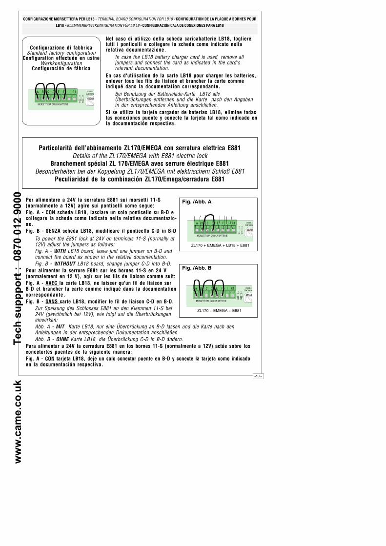
Configurazione di fabbricaStandard factory configuration
Configuration effectuée en usineWerkkonfiguration
Configuración de fábrica
� � � � �
��� �������������������
�� � �����
���������
�������
Particolarità dell’abbinamento ZL170/EMEGA con serratura elettrica E881Details of the ZL170/EMEGA with E881 electric lock
Branchement spécial ZL 170/EMEGA avec serrure électrique E881Besonderheiten bei der Koppelung ZL170/EMEGA mit elektrischem Schloß E881
Peculiaridad de la combinación ZL170/Emega/cerradura E881
Per alimentare a 24V la serratura E881 sui morsetti 11-S(normalmente a 12V) agire sui ponticelli come segue:Fig. A - CON scheda LB18, lasciare un solo ponticello su B-D ecollegare la scheda come indicato nella relativa documentazio-ne.Fig. B - SENZA scheda LB18, modificare il ponticello C-D in B-D
To power the E881 lock at 24V on terminals 11-S (normally at12V) adjust the jumpers as follows:Fig. A - WITH LB18 board, leave just one jumper on B-D andconnect the board as shown in the relative documentation.Fig. B - WITHOUT LB18 board, change jumper C-D into B-D.
Pour alimenter la serrure E881 sur les bornes 11-S en 24 V(normalement en 12 V), agir sur les fils de liaison comme suit:Fig. A - AVEC la carte LB18, ne laisser qu'un fil de liaison surB-D et brancher la carte comme indiqué dans la documentationcorrespondante.Fig. B - SANS carte LB18, modifier le fil de liaison C-D en B-D.
Zur Speisung des Schlosses E881 an den Klemmen 11-S bei24V (gewöhnlich bei 12V), wie folgt auf die Überbrückungeneinwirken:Abb. A - MIT Karte LB18, nur eine Überbrückung an B-D lassen und die Karte nach denAnleitungen in der entsprechenden Dokumentation anschließen.Abb. B - OHNE Karte LB18, die Überbrückung C-D in B-D ändern.
Para alimentar a 24V la cerradura E881 en los bornes 11-S (normalmente a 12V) actúe sobre losconectortes puentes de la siguiente manera:Fig. A - CON tarjeta LB18, deje un solo conector puente en B-D y conecte la tarjeta como indicadoen la documentación respectiva.
� � � � �
��� �������������������
�� � �����
���������
�������
Fig. /Abb. A
ZL170 + EMEGA + LB18 + E881
� � � � �
��� �������������������
�� � �����
���������
�������
Fig. /Abb. B
ZL170 + EMEGA + E881
ww
w.c
am
e.c
o.u
k
T
ec
h s
up
pp
ort
:
08
70
01
2 9
00
0
-18-
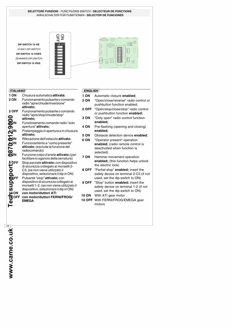
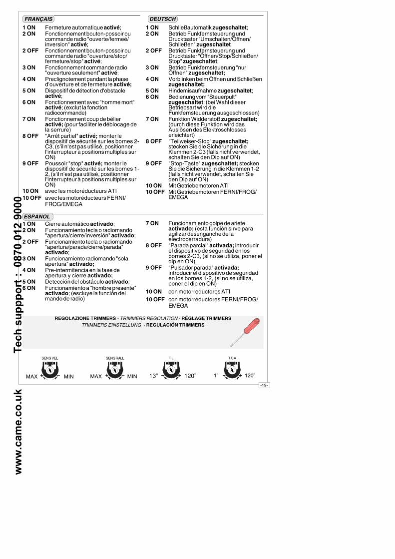
1 ON Chiusura automatica attivata;2 ON Funzionamento pulsante o comando
radio "apre/chiude/inversione"attivato;
2 OFF Funzionamento pulsante o comandoradio "apre/stop/chiude/stop"attivato;
3 ON Funzionamento comando radio "soloapertura" attivato;
4 ON Prelampeggio in apertura e in chiusuraattivato;
5 ON Rilevazione dell'ostacolo attivato;6 ON Funzionamento a "uomo presente"
attivato; (esclude la funzione delradiocomando)
7 ON Funzione colpo d'ariete attivato; (perfacilitare lo sgancio della serratura)
8 OFF Stop parziale attivato; con dispositivodi sicurezza collegato ai morsetti 2-C3, (se non viene utilizzato ildispositivo, selezionare il dip in ON)
9 OFF Pulsante "stop" attivato; condispositivo di sicurezza collegato aimorsetti 1-2, (se non viene utilizzato ildispositivo, selezionare il dip in ON)
10 ON con motoriduttori ATI10 OFF con motoriduttori FERNI/FROG/
EMEGA
ITALIANO
1 ON Automatic closure enabled; 2 ON "Open/close/reverse" radio control or
pushbutton function enabled; 2 OFF "Open/stop/close/stop" radio control
or pushbutton function enabled; 3 ON "Only open" radio control function
enabled; 4 ON Pre-flashing (opening and closing)
enabled; 5 ON Obstacle detection device enabled; 6 ON "Operator present" operation
enabled; (radio remote control isdeactivated when function isselected)
7 ON Hammer movement operationenabled; (this function helps unlockthe electric lock)
8 OFF "Partial-stop" enabled; insert thesafety device on terminal 2-C3 (if notused, set the dip-switch to ON)
9 OFF "Stop" button enabled; insert thesafety device on terminal 1-2 (if notused, set the dip-switch to ON)
10 ON With ATI gear motor10 OFF With FERNI/FROG/EMEGA gear
motors
ENGLISH
21
34
56
78
91
0
��
DIP-SWITCH 10 VIE
10-WAY DIP-SWITCH
DIP-SWITCH 10 VOIES
ZEHNWEG-DIP-SWITCH
DIP-SWITCH 10 VÍAS
21
34
56
78
910
ONO
NO
FF
SELETTORE FUNZIONI - FUNCTIUONS SWITCH - SELECTEUR DE FONCTIONS WÄHLSCHALTER FÜR FUNKTIONEN - SELECTOR DE FUNCIONES
ww
w.c
am
e.c
o.u
k
T
ec
h s
up
pp
ort
:
08
70
01
2 9
00
0
-19-
1 ON Cierre automático activado;2 ON Funcionamiento tecla o radiomando
"apertura/cierre/inversión" activado;2 OFF Funcionamiento tecla o radiomando
"apertura/parada/cierre/parada"activado;
3 ON Funcionamiento radiomando "solaapertura" activado;
4 ON Pre-intermitencia en la fase deapertura y cierre activado;
5 ON Detección del obstáculo activado;6 ON Funcionamiento a "hombre presente"
activado; (escluye la función delmando de radio)
7 ON Funcionamiento golpe de arieteactivado; (esta función sirve paraagilizar desenganche de laelectrocerradura)
8 OFF "Parada parcial" activada; introducirel dispositivo de seguridad en losbornes 2-C3, (si no se utiliza, poner eldip en ON)
9 OFF "Pulsador parada" activada;introducir el dispositivo de seguridaden los bornes 1-2, (si no se utiliza,poner el dip en ON)
10 ON con motorreductores ATI10 OFF con motorreductores FERNI/FROG/
EMEGA
ESPANOL
1 ON Fermeture automatique activé;2 ON Fonctionnement bouton-possoir ou
commande radio "ouverte/fermeé/inversion" activé;
2 OFF Fonctionnement bouton-possoir oucommande radio "ouverture/stop/fermeture/stop" activé;
3 ON Fonctionnement commande radio"ouverture seulement" activé;
4 ON Preclignotement pandant la phased'ouverture et de fermeture activé;
5 ON Dispositif de détection d'obstacleactivé;
6 ON Fonctionnement avec "homme mort"activé; (exclut la fonctionradiocommande)
7 ON Fonctionnement coup de bélieractivé; (pour faciliter le déblocage dela serrure)
8 OFF "Arrêt partiel" activé; monter ledispositif de sécurité sur les bornes 2-C3, (s'il n'est pas utilisé, positionnerl'interrupteur à positions multiples surON)
9 OFF Poussoir "stop" activé; monter ledispositif de sécurité sur les bornes 1-2, (s'il n'est pas utilisé, positionnerl'interrupteur à positions multiples surON)
10 ON avec les motoréducteurs ATI10 OFF avec les motoréducteurs FERNI/
FROG/EMEGA
FRANÇAIS
1 ON Schließautomatik zugeschaltet;2 ON Betrieb Funkfernsteuerung und
Drucktaster "Umschalten/Öffnen/Schließen" zugeschaltet
2 OFF Betrieb Funkfernsteuerung undDrucktaster "Öffnen/Stop/Schließen/Stop" zugeschaltet;
3 ON Betrieb Funkfernsteuerung "nurÖffnen" zugeschaltet;
4 ON Vorblinken beim Öffnen und Schließenzugeschaltet;
5 ON Hindemisaufnahme zugeschaltet;6 ON Bedienung vom "Steuerpult"
zugeschaltet; (bei Wahl dieserBetriebsart wird dieFunkfernsteuerung ausgeschlossen)
7 ON Funktion Widderstoß zugeschaltet;(durch diese Funktion wird dasAuslösen des Elektroschlosseserleichtert)
8 OFF "Teilweiser-Stop" zugeschaltet;stecken Sie die Sicherung in dieKlemmen 2-C3 (falls nicht verwendet,schalten Sie den Dip auf ON)
9 OFF "Stop-Taste" zugeschaltet; steckenSie die Sicherung in die Klemmen 1-2(falls nicht verwendet, schalten Sieden Dip auf ON)
10 ON Mit Getriebemotoren ATI10 OFF Mit Getriebemotoren FERNI/FROG/
EMEGA
DEUTSCH
REGOLAZIONE TRIMMERS - TRIMMERS REGOLATION - RÉGLAGE TRIMMERSTRIMMERS EINSTELLUNG - REGULACIÓN TRIMMERS
MAX MIN
SENS RALL
MAX MIN
T C A
1” 120”
T L
13” 120”
SENS VEL
ww
w.c
am
e.c
o.u
k
T
ec
h s
up
pp
ort
:
08
70
01
2 9
00
0
-20-
� � � �� �� �
ZL170
COLLEGAMENTI QUADRO/MOTORIDUTTORE - CONTROL PANEL/GEAR MOTOR CONNECTIONSBRANCHEMENTS ARMOIRE/ MOTORÉDUCTEUR
ANSCHLÜSSE SCHALTTAFEL/GETRIEBEMOTOR - CONEXIONES CUADRO/MOTORREDUCTOR
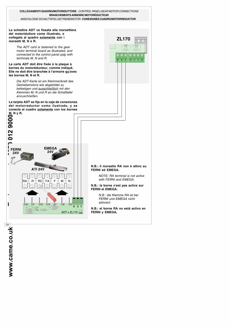
La schedina ADT va fissata alla morsettieradel motoriduttore come illustrato, ecollegata al quadro solamente con imorsetti M, N e R.
The ADT card is fastened to the gearmotor terminal board as illustrated, andconnected to the control panel only withterminals M, N and R.
La carte ADT doit être fixée à la plaque àbornes du motoréducteur, comme indiqué.Elle ne doit être branchée à l'armoire qu'avecles bornes M, N et R.
Die ADT-Karte ist am Klemmenbrett desGetriebemotors wie abgebildet zubefestigen und ausschließlich mit denKlemmen M, N und R an die Schalttafelanzuschließen.
La tarjeta ADT se fija en la caja de conexionesdel motorreductor como ilustrado, y seconecta al cuadro solamente con los bornesM, N y R.
N.B.: il morsetto RA non è attivo suFERNI ed EMEGA.
NOTE: RA terminal is not activewith FERNI and EMEGA.
N.B.: la borne n'est pas active surFERNI et EMEGA.
N.B.: die Klemme RA ist beiFERNI und EMEGA nichtaktiviert.
N.B.: el borne RA no está activo enFERNI y EMEGA,
ATI 24V
12
�� � �� � � �� � �
ADT x ZL170
FERNI24V
EMEGA24V
RA R RC FA F M N
ww
w.c
am
e.c
o.u
k
T
ec
h s
up
pp
ort
:
08
70
01
2 9
00
0
-21-
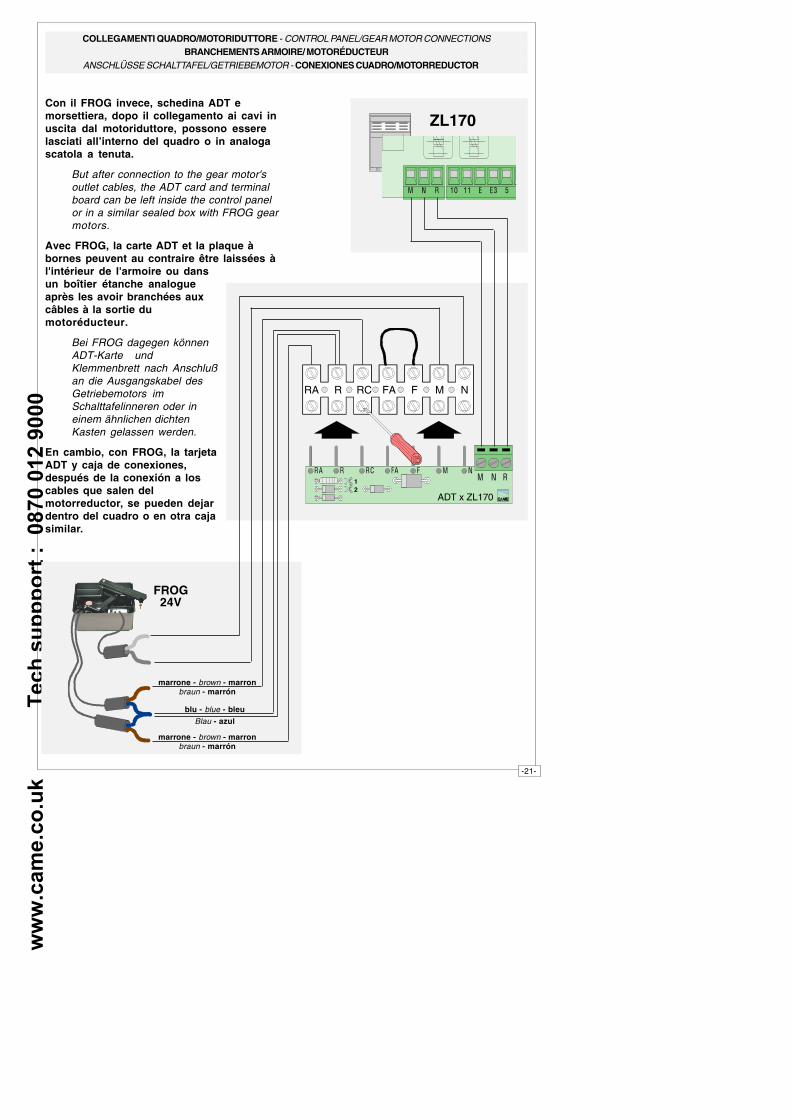
� � � �� �� � �
ZL170
FROG24V
marrone - brown - marronbraun - marrón
blu - blue - bleuBlau - azul
marrone - brown - marronbraun - marrón
Con il FROG invece, schedina ADT emorsettiera, dopo il collegamento ai cavi inuscita dal motoriduttore, possono esserelasciati all’interno del quadro o in analogascatola a tenuta.
But after connection to the gear motor'soutlet cables, the ADT card and terminalboard can be left inside the control panelor in a similar sealed box with FROG gearmotors.
Avec FROG, la carte ADT et la plaque àbornes peuvent au contraire être laissées àl'intérieur de l'armoire ou dansun boîtier étanche analogueaprès les avoir branchées auxcâbles à la sortie dumotoréducteur.
Bei FROG dagegen könnenADT-Karte undKlemmenbrett nach Anschlußan die Ausgangskabel desGetriebemotors imSchalttafelinneren oder ineinem ähnlichen dichtenKasten gelassen werden.
En cambio, con FROG, la tarjetaADT y caja de conexiones,después de la conexión a loscables que salen delmotorreductor, se pueden dejardentro del cuadro o en otra cajasimilar.
RA R RC FA F M N
12
�� � �� � � �� � �
ADT x ZL170
COLLEGAMENTI QUADRO/MOTORIDUTTORE - CONTROL PANEL/GEAR MOTOR CONNECTIONSBRANCHEMENTS ARMOIRE/ MOTORÉDUCTEUR
ANSCHLÜSSE SCHALTTAFEL/GETRIEBEMOTOR - CONEXIONES CUADRO/MOTORREDUCTOR
ww
w.c
am
e.c
o.u
k
T
ec
h s
up
pp
ort
:
08
70
01
2 9
00
0
-22-
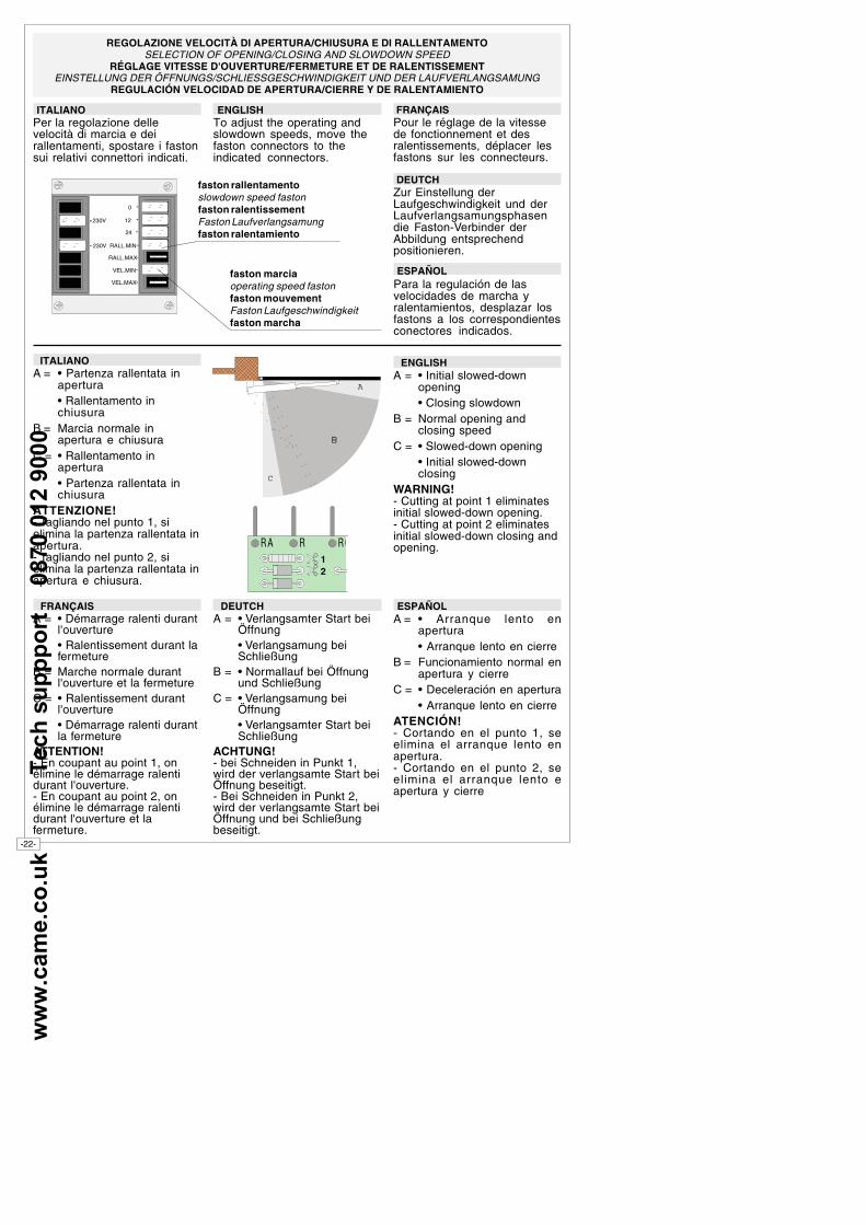
ITALIANOPer la regolazione dellevelocità di marcia e deirallentamenti, spostare i fastonsui relativi connettori indicati.
REGOLAZIONE VELOCITÀ DI APERTURA/CHIUSURA E DI RALLENTAMENTOSELECTION OF OPENING/CLOSING AND SLOWDOWN SPEED
RÉGLAGE VITESSE D'OUVERTURE/FERMETURE ET DE RALENTISSEMENTEINSTELLUNG DER ÖFFNUNGS/SCHLIESSGESCHWINDIGKEIT UND DER LAUFVERLANGSAMUNG
REGULACIÓN VELOCIDAD DE APERTURA/CIERRE Y DE RALENTAMIENTO
ENGLISHTo adjust the operating andslowdown speeds, move thefaston connectors to theindicated connectors.
FRANÇAISPour le réglage de la vitessede fonctionnement et desralentissements, déplacer lesfastons sur les connecteurs.
DEUTCHZur Einstellung derLaufgeschwindigkeit und derLaufverlangsamungsphasendie Faston-Verbinder derAbbildung entsprechendpositionieren.
230V
230V
0
12
24
RALL.MIN
RALL.MAX
VEL.MIN
VEL.MAX
faston rallentamentoslowdown speed fastonfaston ralentissementFaston Laufverlangsamungfaston ralentamiento
faston marciaoperating speed fastonfaston mouvementFaston Laufgeschwindigkeitfaston marcha
C
A
ITALIANOA = • Partenza rallentata in
apertura• Rallentamento inchiusura
B = Marcia normale inapertura e chiusura
C = • Rallentamento inapertura• Partenza rallentata inchiusura
ATTENZIONE!- Tagliando nel punto 1, sielimina la partenza rallentata inapertura.- Tagliando nel punto 2, sielimina la partenza rallentata inapertura e chiusura.
ENGLISHA = • Initial slowed-down
opening• Closing slowdown
B = Normal opening andclosing speed
C = • Slowed-down opening• Initial slowed-downclosing
WARNING!- Cutting at point 1 eliminatesinitial slowed-down opening.- Cutting at point 2 eliminatesinitial slowed-down closing andopening.
FRANÇAISA = • Démarrage ralenti durant
l'ouverture• Ralentissement durant lafermeture
B = Marche normale durantl'ouverture et la fermeture
C = • Ralentissement durantl'ouverture• Démarrage ralenti durantla fermeture
ATTENTION!- En coupant au point 1, onélimine le démarrage ralentidurant l'ouverture.- En coupant au point 2, onélimine le démarrage ralentidurant l'ouverture et lafermeture.
DEUTCHA = • Verlangsamter Start bei
Öffnung• Verlangsamung beiSchließung
B = • Normallauf bei Öffnungund Schließung
C = • Verlangsamung beiÖffnung• Verlangsamter Start beiSchließung
ACHTUNG!- bei Schneiden in Punkt 1,wird der verlangsamte Start beiÖffnung beseitigt.- Bei Schneiden in Punkt 2,wird der verlangsamte Start beiÖffnung und bei Schließungbeseitigt.
ESPAÑOLA = • Arranque lento en
apertura• Arranque lento en cierre
B = Funcionamiento normal enapertura y cierre
C = • Deceleración en apertura• Arranque lento en cierre
ATENCIÓN!- Cortando en el punto 1, seelimina el arranque lento enapertura.- Cortando en el punto 2, seelimina el arranque lento eapertura y cierre
ESPAÑOLPara la regulación de lasvelocidades de marcha yralentamientos, desplazar losfastons a los correspondientesconectores indicados.
12
�� � ��