MANUALE DI MONTAGGIO DEL REGOLAT ORE “NC+PI” PER POMPE … · manuale di montaggio del regolat...
16
MANUALE DI MONTAGGIO DEL REGOLATORE “NC+PI” PER POMPE H1V “NC+PI” CONTROL FOR H1V PUMPS ASSEMBLY PROCEDURE MANUAL
Transcript of MANUALE DI MONTAGGIO DEL REGOLAT ORE “NC+PI” PER POMPE … · manuale di montaggio del regolat...
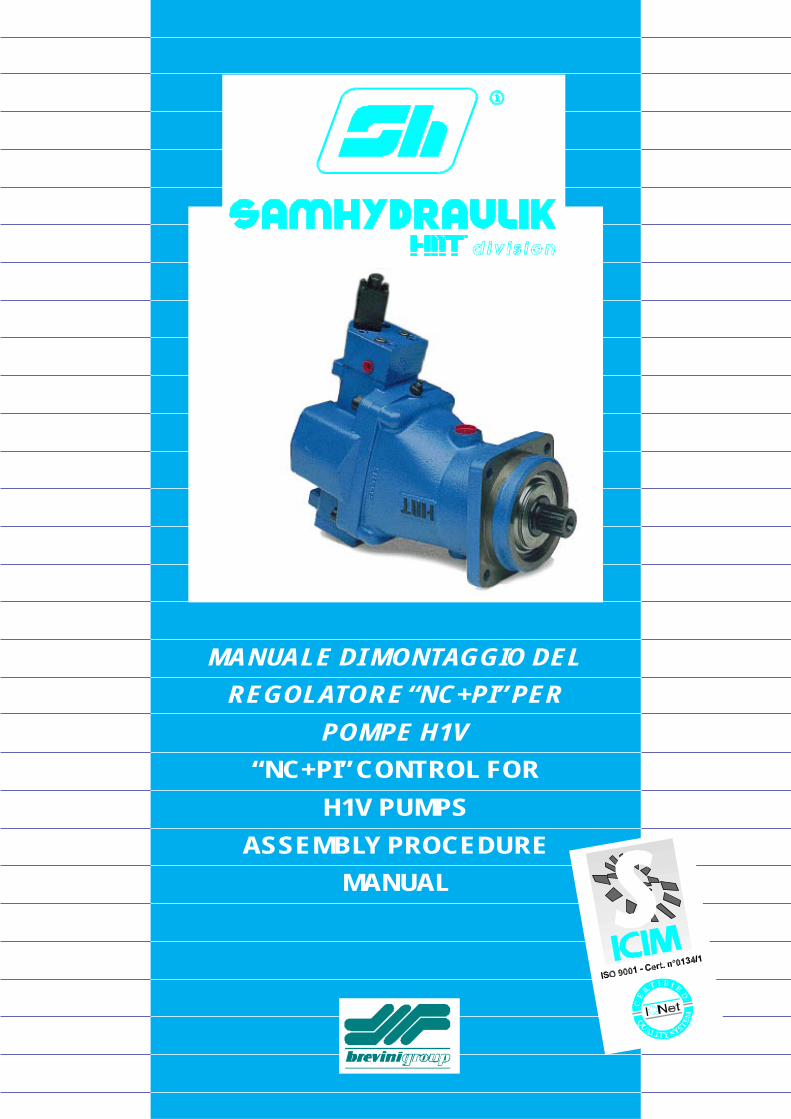
MANUALE DI MONTAGGIO DEL
REGOLATORE “NC+PI” PER
POMPE H1V
“NC+PI” CONTROL FOR
H1V PUMPS
ASSEMBLY PROCEDURE
MANUAL
2
INDICECONTENTS
SMONTAGGIO E MONTAGGIO .................................. 3
1 - PREMESSA .......................................................... 3 2 - SMONTAGGIO REGOLATORE ............................ 3 3 - VERIFICA REGOLATORE .................................... 4 4 - RIMONTAGGIO REGOLATORE .......................... 5
ATTREZZI RICHIESTI .................................................. 9
DISTINTA BASE ......................................................... 10
ASSIEMATO REGOLATORE ......................................11
COPPIE DI SERRAGGIO ........................................... 12
COMBINAZIONI PILOTA - MOLLE - PORTAPILOTA..... 14
DISASSEMBLY AND ASSEMBLY ............................... 3
1 - INTRODUCTION .................................................. 3 2 - CONTROL DISASSEMBLY .................................. 3 3 - CHECKING THE CONTROL ................................ 4 4 - CONTROL REASSEMBLY ................................... 5
REQUIRED TOOLS ...................................................... 9
SPARE PARTS LIST .................................................. 10
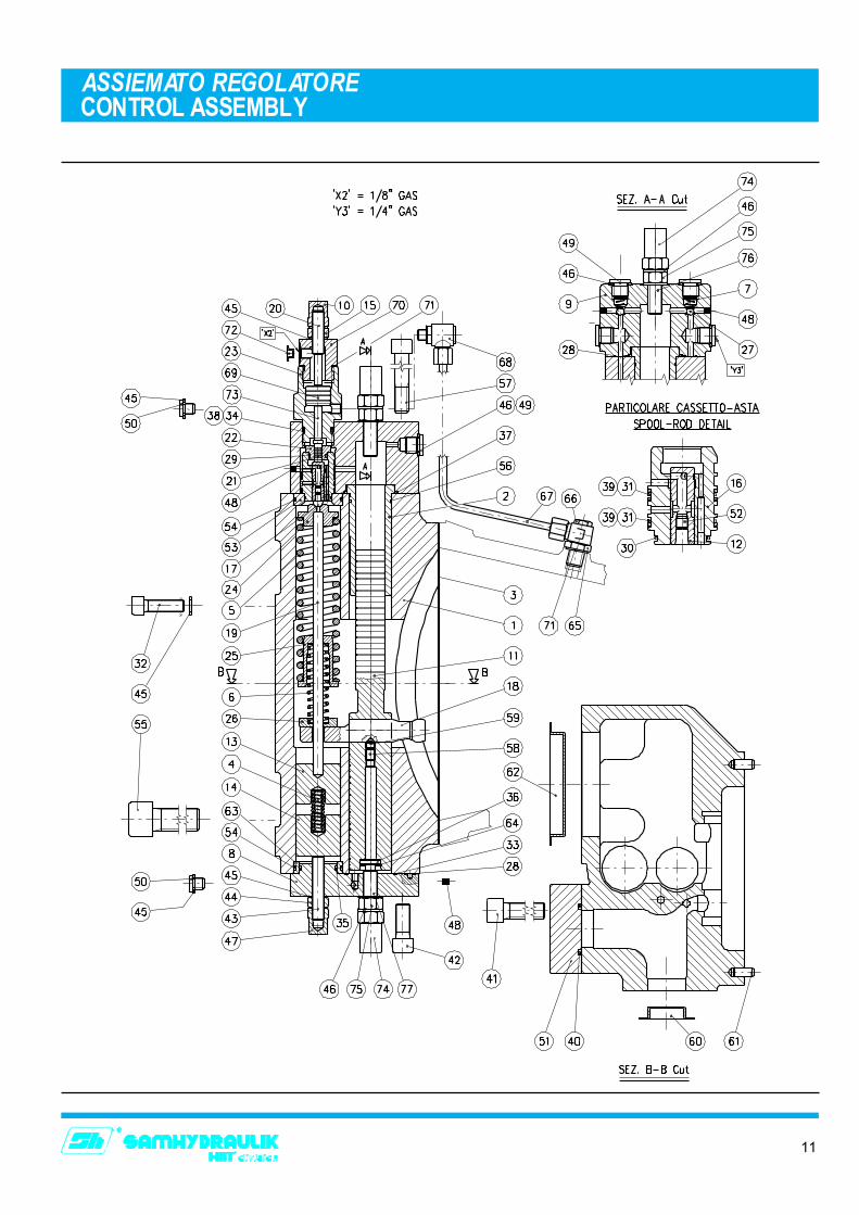
CONTROL ASSEMBLY...............................................11
TIGHTENING TORQUES ........................................... 12
PILOT - PILOT HOUSING - SPRINGS COMBINATIONS .. 14
3
SMONTAGGIO E MONTAGGIO DISASSEMBLY AND ASSEMBLY
1 - PREMESSA
Le procedure passo-passo di smontaggio e rimontaggiodescritte di seguito riguardano le unità tipo H1V �NC+PI�.Per procedere allo smontaggio e rimontaggio dell�unità ènecessario disporre di un piano di lavoro pulito e sufficien-temente illuminato, di utensili adeguati (vedi a pagina 9 delpresente manuale), di una chiave dinamometrica, di strac-ci non sfilacciabili, di detergenti sgrassanti e di grasso edolio per la lubrificazione. Ogni altro materiale necessarioverrà citato di volta in volta.
2 - SMONTAGGIO REGOLATORE
Per le operazioni descritte di seguito, se non diversamenterichiesto, fare riferimento al disegno sezionato regolatore apagina 11 del presente manuale.
2.1 Rimuovere il tubo di raccordo 67 tra il corpo pompae il regolatore svitando il raccordo orientabile da 1/8� 68 ed il raccordo orientabile da 1/4� 66.
2.2 Svitare le quattro viti 55 che fissano il coperchiodistributore 1 al corpo pompa (solo su H1V 160 eH1V 226: svitare anche le due viti 32). Rimuoverel�assiemato comando dal corpo pompa facendo at-tenzione a non far cadere il distributore .
2.3 Rimuovere il dado cieco 10, il dado 15 e le rondellein rame 45. Svitare il grano 20, il tappo di registroper comando NC+PI 70 ed estrarre il pistone perNC+PI 69 e la spina 73. Rimuovere il cappellottoper NC+PI 23, l�O-Ring 34 e l�anello antiestrusione38. Estrarre il pilota 21.
2.4 Svitare le 4 viti 57 che fissano il cappellotto supe-riore 9 al coperchio distributore. Rimuovere il cap-pellotto superiore 9. Rimuovere gli O-Ring 37 e 28.Estrarre dal cappellotto superiore 9 il cassetto pro-porzionale 16. Rimuovere il portapilota 22, gli O-Ring 29, 30, 31 e gli anelli antiestrusione 39. Ri-muovere l�asta proporzionale 12 e lo snodo di cen-traggio 17.
2.5 Solo per le cilindrate 160 e 226 rimuovere l�anello53 e l�O-Ring 54. Capovolgendo il coperchio estrarreil guidamolla superiore 24, le molle 5 e 6, il porta-molle 25, il guidamolla 26 e la prolunga 19.
2.6 Svitare le quattro viti 42 che fissano il cappellottoinferiore 8 al coperchio distributore 1. Rimuovere ilcappellotto inferiore 8. Rimuovere gli O-Ring 28 e
1 - INTRODUCTION
The step by step disassembly and reassembly proceduredescribed below concerns the H1V �NC+PI� pumps. In orderto perform the disassembly and assembly of the namedunits, it is recommended to work on a clean and properlyilluminated bench with proper tools (see at page 9 of thismanual), a torque wrench, non threading cleaning rags,de-greasing detergent, oil and grease for lubrication. Anyother required material will be described later. All sealsand O-Rings must be replaced every time they aredisassembled, even if they seem in good conditions.
2 - CONTROL DISASSEMBLY
For the following procedure, if not otherwise required, referto the control cutaway drawing at page 11 of this manual.
2.1 Remove the pipe 67 between the pump casing andthe control unscrewing the 1/8� inch swivel fitting68 and the 1/4� inch swivel fitting 66.
2.2 Unscrew the four screws 55 which fix the distributorcover 1 to the pump�s casing (H1V 160 and H1V226 only: unscrew the two screws 32, too). Removethe control assembly from the pump casingassembly. Take care not to let the valve plate fall.
2.3 Remove the cap nut 10, the screw nut 15 and thewasher 45. Unscrew the grub screw 20 and theadjustment plug for NC+Pi control 70. Extract theNC+PI control�s piston 69 and the pin 73. Removethe NC+PI control�s adjustment plug 23, the O-Ring34 and the anti-extrusion ring 38. Extract the pilot21.
2.4 Unscrew the four screws 57 which fix the uppercap 9 to the distributor cover 1. Remove the uppercap 9. Remove the O-Rings 37 and 28. Extract theproportional spool 16 from the upper cap 9. Removethe pilot housing 22, the O-Rings 29, 30, 31 andthe anti-extrusion rings 39. Remove the proportionalrod 12 and the centering joint 17.
2.5 Only for H1V 160 and H1V 226 remove the ring 53and the O-Ring 54. Turning upside down thedistributor cover extract the spring guide 24, thesprings 5 and 6, the spring guide 24, the springguide 25 and the extension 19.
2.6 Unscrew the four screws 42 which fix the lower cap8 to the distributor cover 1. Remove the lower cap8. Remove the O-Rings 28 and 33. (H1V 226 only:
4
SMONTAGGIO E MONTAGGIODISASSEMBLY AND ASSEMBLY
33. (Solo su H1V 160 e H1V 226: rimuovere anchel�O-Ring 35. Solo su H1V 226 sfilare l�anello 63 erimuovere l�O-Ring 54).
2.7 Sfilare, nell�ordine, il tappo di registro 14, la molla 4e il tappo di registro 13 dal loro alloggiamento nelcoperchio distributore 1.
2.8 Rimuovere l�anello elastico 64 dalla sua sede nelpistone di comando 11 ed estrarre il distanziale dibattuta 36. Svitare i grani 58 e 59 che vincolano losnodo di comando 18 al pistone di comando 11.Sfilare lo snodo di comando 18 e, fatto ciò, sfilare ilpistone di comando 11 dal suo alloggiamento nelcoperchio distributore 1. Rimuovere la bussola percappellotto 2 dal suo alloggiamento nel coperchiodistributore 1 e rimuovere l�O-Ring 56.
2.9 Verificare le condizioni dei singoli componenti se-guendo le fasi del ciclo di verifica descritte nel pa-ragrafo 3 del presente manuale.
3 - VERIFICA REGOLATORE
3.1 Con riferimento al punto 2.2 del ciclo di smontag-gio, verificare le piste di scorrimento del distributo-re e del coperchio distributore 1: Esse non devonopresentare scalini o rigature eccessive; essi sonocausate dalla presenza di impurità nel fluido idrau-lico. Controllare la sporgenza del distributore dalcoperchio distributore. Se i componenti suddetti sipresentassero eccessivamente usurati, essi andran-no sostituiti.
3.2 Con riferimento al punto 2.3 del ciclo di smontag-gio, smontare il pistone 69 e la spina 73 e verificar-ne le condizioni e la scorrevolezza. I componentinon devono presentare rigature e non devono im-puntarsi nelle loro sedi. Se i componenti sono dan-neggiati, sostituire i componenti danneggiati. In casocontrario, pulire i componenti, lubrificarli e rimon-tarli.
3.3 Con riferimento al punto 2.4 del ciclo di smontag-gio, smontare il cassetto e l�asta proporzionale everificare le condizioni del cassetto, dell�asta e del-le molle: i componenti non devono presentare riga-ture o scheggiature evidenti e mentre le molle de-vono essere integre; se i componenti appaiono dan-neggiati, questo è dovuto alla presenza di impuritànel fluido idraulico, per cui andranno verificate lecondizioni di filtraggio. Se i componenti sono dan-neggiati, sostituire i componenti danneggiati. In casocontrario, pulire i componenti, lubrificarli e rimon-tarli.
3.4 Controllare con attenzione che i condotti di passag-gio del fluido idraulico, presenti nel cassetto, nel-l�asta, nei cappellotti superiore ed inferiore e nel
extract the ring 63 and remove the O-Ring 54. H1V160 and H1V 226 only: remove O-Ring 35, too).
2.7 Remove the adjustment plug 14, the spring 4 andthe adjustment plug 13 from their housing indistributor cover 1.
2.8 Remove the circlip 64 from its groove in the controlpiston 11 and extract the spacer 36. Unscrew thetwo grub screws 58 and 59 which dowel the controljoint 18 to the control piston 11. Extract the controljoint 18 from the control piston 11 and, after this,remove the control piston 11 from the distributorcover 1. Extract the cap�s bushing 2 from thedistributor cover 1 and remove the O-Ring 56.
2.9 Check all the components, carefully following theprocedures described in chapter 3 of this manual.
3 - CHECKING THE CONTROL
3.1 With reference to point 2.2 of the disassemblingprocedure, check the valve plate and distributorcover 1 sliding tracks: they must not be scored ordented; this is caused by the presence of foreignparticles in the hydraulic fluid. Check the valve plateprotrusion out of the distributor cover 1. If the namedcomponents are too much worn out, replace them.
3.2 With reference to point 2.3 of the disassemblingprocedure, check the piston 69 and the pin 73: theymust not be scored or dented and they must movesmoothly into their seat. If components aredamaged, replace them. Otherwise, clean thecomponents, oil them and reassemble them.
3.3 With reference to point 2.4 of the disassemblingprocedure, check the control rod 12, the controlspool 16 and the springs: they must not be scoredor dented and the springs must be undamaged. Ifthe components are damaged, this would be causedby the presence of foreign particles or dirt in thehydraulic fluid; check the filtration of the hydraulicfluid. If components are damaged, replace them.Otherwise, clean the components, oil them andreassemble them.
3.4 Look carefully at the holes into the proportionalspool, into the proportional rod, into the lower andupper caps and into the distributor cover. They must
5
SMONTAGGIO E MONTAGGIODISASSEMBLY AND ASSEMBLY
coperchio distributore, non siano ostruiti da impuri-tà. Se risultassero ostruiti pulire tali condotti atten-tamente.
3.5 Con riferimento al punto 2.8 del ciclo di smontag-gio, smontare il pistone di comando cilindrata 11 everificare che esso non sia rigato o scheggiato;questo è causato dalla presenza di impurità nel fluidoidraulico. Verificare le tolleranze di accoppiamentofra pistone di comando 11 ed alloggiamento. Se ilcomponente risultasse eccessivamente danneggia-to sostituirlo.
4 - RIMONTAGGIO REGOLATORE
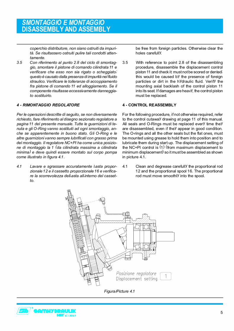
Per le operazioni descritte di seguito, se non diversamenterichiesto, fare riferimento al disegno sezionato regolatore apagina 11 del presente manuale. Tutte le guarnizioni di te-nuta e gli O-Ring vanno sostituiti ad ogni smontaggio, an-che se apparentemente in buono stato. Gli O-Ring e lealtre guarnizioni vanno sempre lubrificati con grasso primadel montaggio. Il regolatore NC+PI ha come unica posizio-ne di montaggio la 1 (da cilindrata massima a cilindrataminima) e deve quindi essere montato sul corpo pompacome illustrato in figura 4.1.
4.1 Lavare e sgrassare accuratamente l�asta propor-zionale 12 e il cassetto proporzionale 16 e verifica-re la scorrevolezza dell�asta all�interno del casset-to.
be free from foreign particles. Otherwise clear theholes carefully.
3.5 With reference to point 2.8 of the disassemblingprocedure, disassemble the displacement controlpiston 11 and check it: must not be scored or dented;this would be caused by the presence of foreignparticles or dirt in the hydraulic fluid. Verify themounting axial backlash of the control piston 11into its seat. If damages are heavy, the control pistonmust be replaced.
4 - CONTROL REASSEMBLY
For the following procedure, if not otherwise required, referto the control cutaway drawing at page 11 of this manual.All seals and O-Rings must be replaced every time theyare disassembled, even if they appear in good condition.The O-rings and all the other seals but the flat ones, mustbe mounted using grease to hold them into position and tolubricate them during start up. The displacement setting ofthe NC+PI control is (1) (from maximum displacement tominimum displacement) so it must be assembled as shownin picture 4.1.
4.1 Clean and degrease carefully the proportional rod12 and the proportional spool 16. The proportionalrod must move smoothly into the spool.
Figura/Picture 4.1
6
SMONTAGGIO E MONTAGGIO DISASSEMBLY AND ASSEMBLY
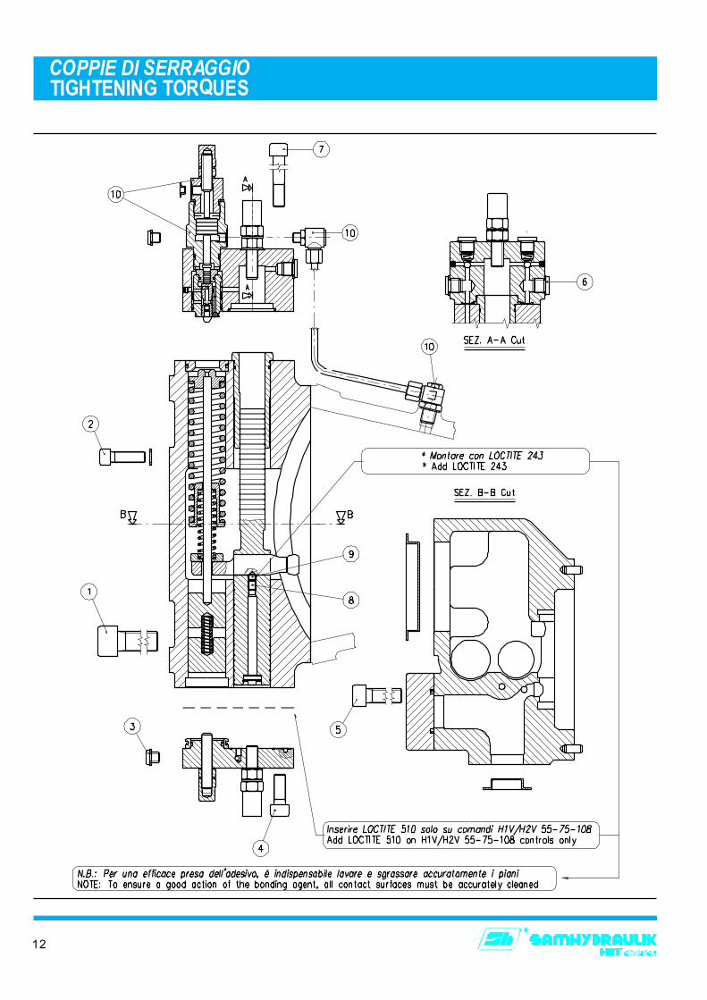
4.2 Avvitare a fondo il grano 52 nell�asta proporzionale12 e bloccarlo con LOCTITE 243. Inserire lo snododi centraggio 17 nella sua sede sull�asta 12 ferman-dolo con del grasso.
4.3 Montare l�O-Ring 30 e i due O-Ring 31 corredati dianelli antiestrusione 39 sul cassetto proporzionale16 e inserire l�asta proporzionale 12 precedente-mente preparata.
4.4 Se assenti montare i 5 expander 48 sul cappellottosuperiore 9 (per un corretto montaggio degli expan-der utilizzare un�apposito punzone e assicurarsi chela cima della sfera rientri di 0.4±0.2 mm rispetto albordo della bussola). Montare le due sfere di rite-gno 27, le due molle 7 ed i 5 tappi 49 corredati dirondelle in rame 46. Se il cappellotto non è maistato utilizzato mediante un punzone ed un martel-lo battere le sfere 27 nella loro sede per creare unatenuta adeguata nel cappellotto. Fermandoli con delgrasso montare i 4 O-Ring 28 nelle loro sedi rica-vate sulla base del cappellotto (per le cilindrate 160e 226 montare anche l�O-Ring 37). Terminare lapreparazione del cappellotto 9 montando il grano76, il dado 75, il dado cieco 74 e le rondelle 46.
4.5 Montare il grano 77, il dado 75, il dado cieco 74 e lerondelle 46 sul cappellotto inferiore 8. Se assentemontare anche l�espander 48 utilizzando la stessaprocedura del punto 4.4. Fermandoli con del gras-so montare i 4 O-Ring 28 e l� O-Ring 33 (per lecilindrate 160 e 226 montare anche l�O-Ring 35 eper la sola cilindrata 226 montare anche l�anello 63e l�O-Ring 54). Terminare la preparazione del cap-pellotto 8 montando i due tappi 50 con le rondelle inrame 45.
4.2 screw the grub screw 52 into the proportional rod12 and lock it using some LOCTITE 243. Usingsome grease insert the centering joint 17 into hisseat on the proportional rod 12.
4.3 Mount the O-Ring 30, the two O-Rings 31 and theanti-extrusion rings 39 onto the proportional spool16 and insert into the spool the proportional rod 12.
4.4 If they are absent, mount the five expander plugs48 into the upper cap 9 (for a correct mounting ofthe expander you must use a proper heading punchand you must be sure that the top of the balldisappears 0.4±0.2 mm below the edge of thesleeve). Insert the two balls 27, the two springs 7and the five plugs 49 with their soft copper washers46. If you use the upper cap for the first time youmust use a proper heading punch and an hammerto hit the balls 27 to create the valve seat. Usinggrease put the four O-Rings 28 into their seats onthe cap (H1V 160 and H1V 226 only: mount the O-Ring 37, too). On the upper cap 9 screw the grubscrew 76, the nut 75 and the cap nuts 74 with theirwashers 46.
4.5 Screw the grub screw 77, the nut 75 and the capnut 74 with their washers 46 into the lower cap 8. Ifit is absent, mount the expander 48 using the sameprocedure explained in point 4.4. Using somegrease fit the four O-Rings 28 and the O-Ring 33into their seats in the caps (H1V 160 and H1V 226only: mount the O-Ring 35. H1V 226 only: mountthe ring 63 and the O-Ring 54). On the lower cap 8screw the two cap nuts 50 with their washers 45.
Figura/Picture 4.2
7
SMONTAGGIO E MONTAGGIO DISASSEMBLY AND ASSEMBLY
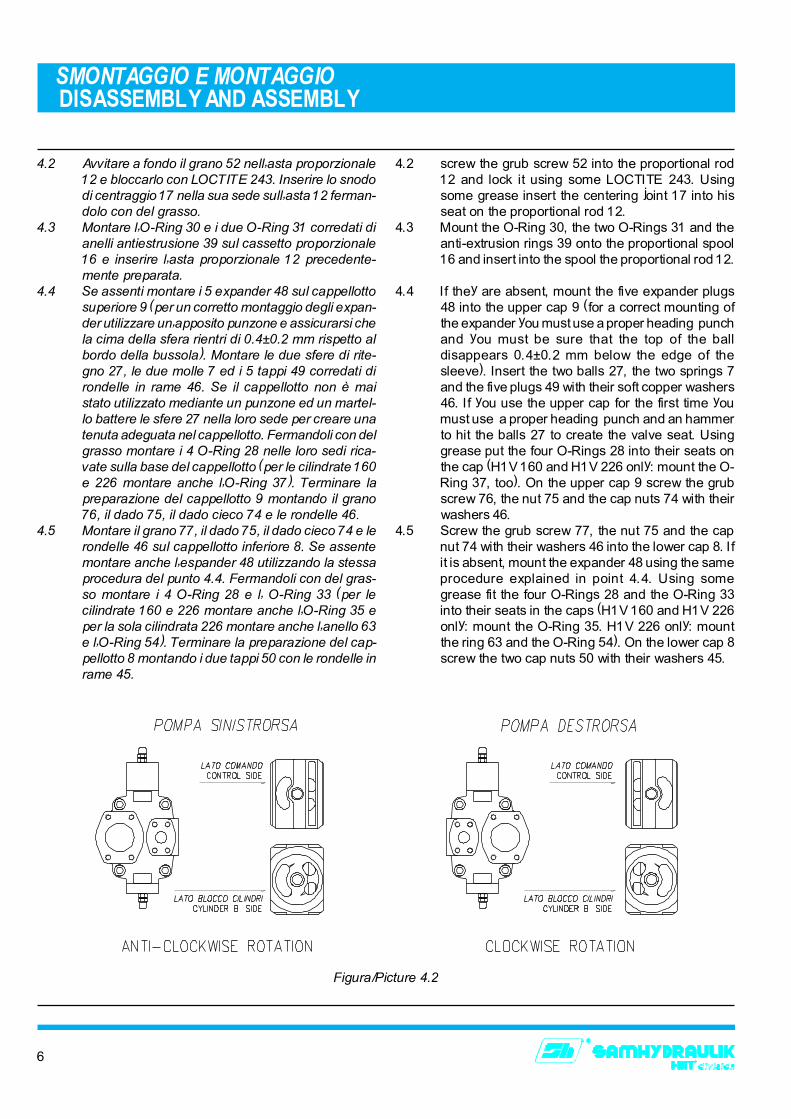
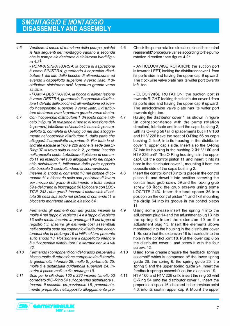
4.6 Verificare il senso di rotazione della pompa, poichéle fasi seguenti del montaggio variano a secondache la pompa sia destrorsa o sinistrorsa (vedi figu-ra 4.2):- POMPA SINISTRORSA: la bocca di aspirazioneè verso SINISTRA, guardando il coperchio distri-butore 1 dal lato delle bocche di alimentazione edavendo il cappellotto superiore 9 verso l�alto. Il di-stributore sinistrorso avrà l�apertura grande versosinistra.- POMPA DESTRORSA: la bocca di alimentazioneè verso DESTRA, guardando il coperchio distribu-tore 1 dal lato delle bocche di alimentazione ed aven-do il cappellotto superiore 9 verso l�alto. Il distribu-tore destrorso avrà l�apertura grande verso destra.
4.7 Con il coperchio distributore 1 disposto come indi-cato in figura (in relazione al senso di rotazione del-la pompa), lubrificare ed inserire la bussola per cap-pellotto 2, completa di O-Ring 56 nel suo alloggia-mento nel coperchio distributore 1, dalla parte chealloggerà il cappellotto superiore 9. Per tutte le ci-lindrate escluse le 160 e 226 anche la sede dell�O-Ring 37 si trova sulla bussola 2, pertanto inserirlonell�apposita sede. Lubrificare il pistone di coman-do 11 ed inserirlo nel suo alloggiamento nel coper-chio distributore 1, infilandolo dalla parte oppostaalla bussola 2 controllandone la scorrevolezza.
4.8 Inserire lo snodo di comando 18 nel pistone di co-mando 11 e bloccarlo nella sua posizione di lavoroper mezzo del grano di riferimento a testa conica59 e del grano di bloccaggio 58 (bloccare con LOC-TITE 243 i due grani). Inserire il distanziale di bat-tuta 36 nella sua sede nel pistone di comando 11 ebloccarlo montando l�anello elastico 64.
4.9 Fermando gli elementi con del grasso inserire lamolla 4 nel tappo di registro 14 e il tappo di registro13 sulla molla. Inserire la prolunga 19 sul tappo diregistro 13. Inserire gli elementi così assemblatinell�apposita sede sul coperchio distributore accer-tandosi che la prolunga 19 si infili nel foro presentesullo snodo 18. Posizionare il cappellotto inferiore8 sul coperchio distributore 1 e serrarlo con le 4 viti42.
4.10 Fermando i componenti con del grasso preparare ilblocco molle di retroazione composto da distanzia-le guidamolla inferiore 26, molla 6, portamolle 25,molla 5 e distanziala guidamolla superiore 24. In-serire il pacco molle sulla prolunga 19.
4.11 Solo per le cilindrate 160 e 226 inserire l�anello 53corredato di O-Ring 54 sul coperchio distributore 1.Inserire Il cassetto proporzionale 16, precedente-mente preparato, nell�apposito alloggiamento pre-
4.6 Check the pump rotation direction, since the controlreassembly procedure varies according to the pumprotation direction (see figure 4.2):
- ANTICLOCKWISE ROTATION: the suction portis towards LEFT, looking the distributor cover 1 fromits ports side and having the upper cap 9 upward.The clockwise valve plate has its wider port towardsleft, too.
- CLOCKWISE ROTATION: the suction port istowards RIGHT, looking the distributor cover 1 fromits ports side and having the upper cap 9 upward.The anticlockwise valve plate has its wider porttowards right, too.
4.7 Having the distributor cover 1 as shown in figure(in correspondence with the pump rotationdirection), lubricate and insert the cap�s bushing 2,with its O-Ring 56 (all displacements but H1V 160and H1V 226 have the seat of O-Ring 56 on cap�sbushing 2, too), into its housing in the distributorcover 1, upper cap�s side. Insert also the O-Ring37 into its housing in the bushing 2 (H1V 160 andH1V 226 only: The O-Ring housing is in the uppercap). Oil the control piston 11 and insert it into itsbore in the distributor cover 1, mounting it from theopposite side of the cap�s bushing 2.
4.8 Insert the control joint 18 into its place in the controlpiston 11 and dowel it into position screwing theconical head grub screw 59 and the locking grubscrew 58 (lock the grub screws using someLOCTITE 243). Insert the beat spacer 36 intoposition on the control piston 11 and fix it mountingthe circlip 64 into its groove in the control piston11.
4.9 Using some grease insert the spring 4 into theadjustment plug 14 and the adjustment plug 13 intothe spring 4. Insert the extension 19 on theadjustment plug 13. Insert the elements abovementioned into the housing in the distributor cover1. Be sure that the extension 19 is inserted into thehole in the control joint 18. Put the lower cap 8 onthe distributor cover 1 and screw it with the fourscrews 42.
4.10 Using some grease prepare the feedback springsassembly which is composed by the lower springguide 26, the spring 6, the spring guide 25, thespring 5 and the upper spring guide 24. Insert thefeedback springs assembly on the extension 19.
4.11 H1V 160 and H1V 226 only: insert the ring 53 whitO-Ring 54 onto the distributor cover 1. Insert theproportional spool 16, obtained in the previous point4.3, into its seat in upper cap 9. Mount the upper
8
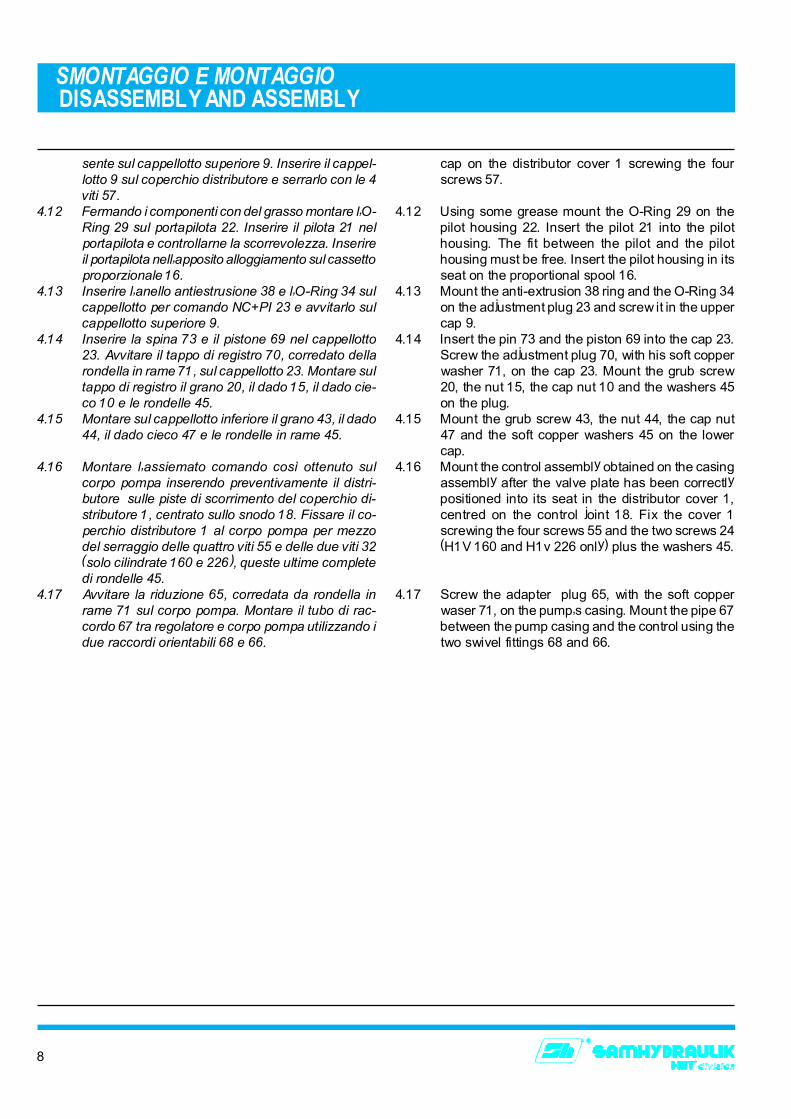
sente sul cappellotto superiore 9. Inserire il cappel-lotto 9 sul coperchio distributore e serrarlo con le 4viti 57.
4.12 Fermando i componenti con del grasso montare l�O-Ring 29 sul portapilota 22. Inserire il pilota 21 nelportapilota e controllarne la scorrevolezza. Inserireil portapilota nell�apposito alloggiamento sul cassettoproporzionale 16.
4.13 Inserire l�anello antiestrusione 38 e l�O-Ring 34 sulcappellotto per comando NC+PI 23 e avvitarlo sulcappellotto superiore 9.
4.14 Inserire la spina 73 e il pistone 69 nel cappellotto23. Avvitare il tappo di registro 70, corredato dellarondella in rame 71, sul cappellotto 23. Montare sultappo di registro il grano 20, il dado 15, il dado cie-co 10 e le rondelle 45.
4.15 Montare sul cappellotto inferiore il grano 43, il dado44, il dado cieco 47 e le rondelle in rame 45.
4.16 Montare l�assiemato comando così ottenuto sulcorpo pompa inserendo preventivamente il distri-butore sulle piste di scorrimento del coperchio di-stributore 1, centrato sullo snodo 18. Fissare il co-perchio distributore 1 al corpo pompa per mezzodel serraggio delle quattro viti 55 e delle due viti 32(solo cilindrate 160 e 226), queste ultime completedi rondelle 45.
4.17 Avvitare la riduzione 65, corredata da rondella inrame 71 sul corpo pompa. Montare il tubo di rac-cordo 67 tra regolatore e corpo pompa utilizzando idue raccordi orientabili 68 e 66.
SMONTAGGIO E MONTAGGIO DISASSEMBLY AND ASSEMBLY
cap on the distributor cover 1 screwing the fourscrews 57.
4.12 Using some grease mount the O-Ring 29 on thepilot housing 22. Insert the pilot 21 into the pilothousing. The fit between the pilot and the pilothousing must be free. Insert the pilot housing in itsseat on the proportional spool 16.
4.13 Mount the anti-extrusion 38 ring and the O-Ring 34on the adjustment plug 23 and screw it in the uppercap 9.
4.14 Insert the pin 73 and the piston 69 into the cap 23.Screw the adjustment plug 70, with his soft copperwasher 71, on the cap 23. Mount the grub screw20, the nut 15, the cap nut 10 and the washers 45on the plug.
4.15 Mount the grub screw 43, the nut 44, the cap nut47 and the soft copper washers 45 on the lowercap.
4.16 Mount the control assembly obtained on the casingassembly after the valve plate has been correctlypositioned into its seat in the distributor cover 1,centred on the control joint 18. Fix the cover 1screwing the four screws 55 and the two screws 24(H1V 160 and H1v 226 only) plus the washers 45.
4.17 Screw the adapter plug 65, with the soft copperwaser 71, on the pump�s casing. Mount the pipe 67between the pump casing and the control using thetwo swivel fittings 68 and 66.
9
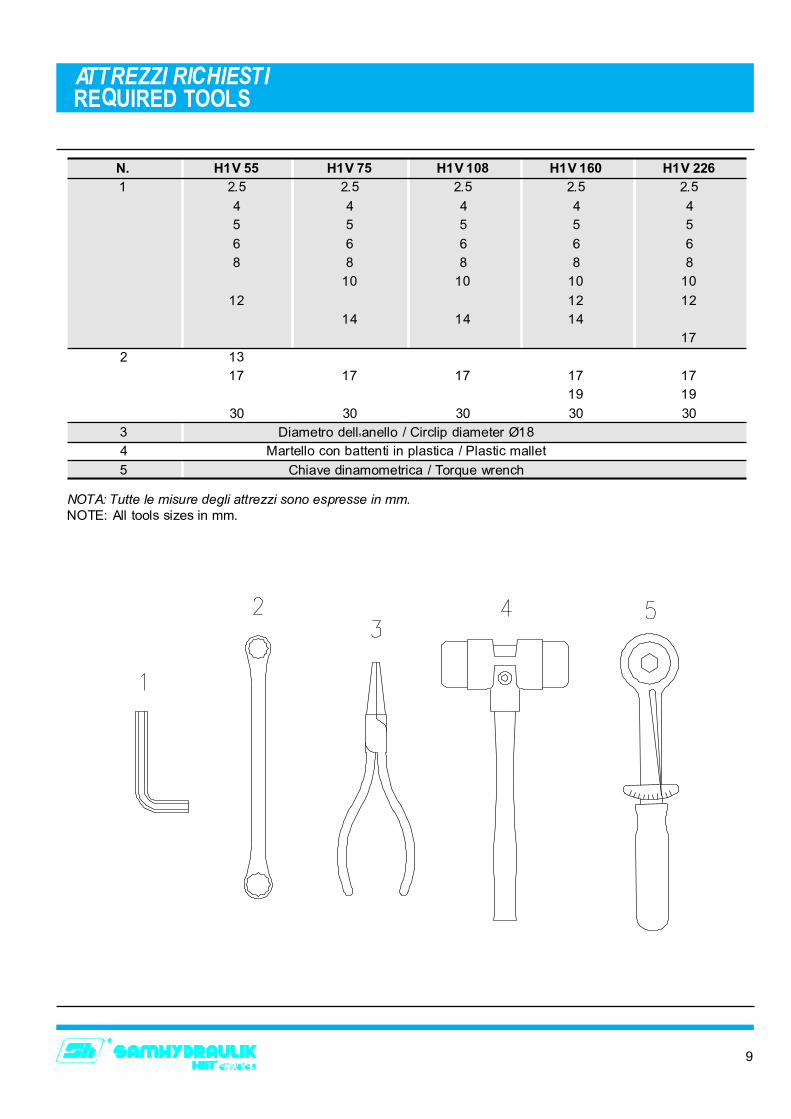
ATTREZZI RICHIESTIREQUIRED TOOLS
5 Chiave dinamometrica / Torque wrench
N. H1V 55 H1V 75 H1V 108 H1V 160 H1V 226
1 2.5 2.5 2.5 2.5 2.5
4 4 4 4 4
10 10 10 10
8 8 8 8 8
6 6 6 6 6
14 14 14
12 12 12
2 13
17
19 19
17 17 17 17 17
30 30 30 30 30
3 Diametro dell�anello / Circlip diameter Ø18
5 5 5 5 5
4 Martello con battenti in plastica / Plastic mallet
NOTA: Tutte le misure degli attrezzi sono espresse in mm.NOTE: All tools sizes in mm.
10
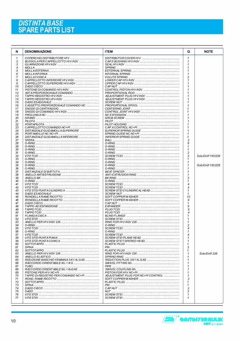
DISTINTA BASE SPARE PARTS LIST
N DENOMINAZIONE ITEM Q NOTE
1 COPERCHIO DISTRIBUTORE H1V ..................................... DISTRIBUTOR COVER H1V ................................................ 12 BUSSOLA PER CAPPELLOTTO H1V/H2V .......................... CAP�S BUSHING H1V/H2V ................................................... 13 GUARNIZIONE H1V/H2V ..................................................... SEAL H1V/H2V ..................................................................... 14 MOLLA ................................................................................. SPRING ................................................................................ 15 MOLLA ESTERNA ................................................................ ESTERNAL SPRING ............................................................. 16 MOLLA INTERNA ................................................................. INTERNAL SPRING .............................................................. 17 MOLLA CONICA ................................................................... VOLUTE SPRING ................................................................. 28 CAPPELLOTTO INFERIORE H1V/H2V ................................ LOWER CAP H1V/H2V ......................................................... 19 CAPPELLOTTO SUPERIORE H1V/H2V .............................. UPPER CAP H1V/H2V .......................................................... 1
10 DADO CIECO ....................................................................... CAP NUT .............................................................................. 111 PISTONE DI COMANDO H1V/H2V ...................................... CONTROL PISTON H1V/H2V .............................................. 112 ASTA PROPORZIONALE COMANDO ................................. PROPORTIONAL ROD ......................................................... 113 TAPPO REGISTRO H1V/H2V .............................................. ADJUSTMENT PLUG H1V/H2V ........................................... 114 TAPPO REGISTRO H1V/H2V .............................................. ADJUSTMENT PLUG H1V/H2V ........................................... 115 DADO ESAGONALE ............................................................ SCREW NUT ........................................................................ 116 CASSETTO PROPORZIONALE COMANDO NC ................. PROPORTIONAL SPOOL .................................................... 117 SNODO DI CENTRAGGIO ................................................... CENTERING JOINT .............................................................. 118 SNODO DI COMANDO H1V/H2V ......................................... CONTROL JOINT H1V/H2V ................................................. 119 PROLUNGA NC ................................................................... NC EXTENSION ................................................................... 120 GRANO ................................................................................ GRUB SCREW ..................................................................... 121 PILOTA ................................................................................. PILOT .................................................................................... 122 PORTAPILOTA ..................................................................... PILOT HOUSING .................................................................. 123 CAPPELLOTTO COMANDO NC+PI ..................................... CAP X CONTROL NC+PI ..................................................... 124 DISTANZIALE GUIDAMOLLA SUPERIORE ......................... SUPERIOR SPRING GUIDE ................................................. 125 PORTAMOLLE NC NC+PI .................................................... SPRING GUIDE NC NC+PI .................................................. 126 DISTANZIALE GUIDAMOLLA INFERIORE ........................... INFERIOR SPRING GUIDE .................................................. 127 SFERA .................................................................................. BALL ..................................................................................... 228 O-RING ................................................................................. O-RING ................................................................................. 829 O-RING ................................................................................. O-RING ................................................................................. 130 O-RING ................................................................................. O-RING ................................................................................. 131 O-RING ................................................................................. O-RING ................................................................................. 232 VITE TCEI ............................................................................. SCREW TCEI ........................................................................ 2 Solo/Only 160/22633 O-RING ................................................................................. O-RING ................................................................................. 134 O-RING ................................................................................. O-RING ................................................................................. 135 O-RING ................................................................................. O-RING ................................................................................. 1 Solo/Only 160/22636 O-RING ................................................................................. O-RING ................................................................................. 137 DISTANZIALE DI BATTUTA .................................................. BEAT SPACER ...................................................................... 138 ANELLO ANTIESTRUSIONE ................................................ ANTI EXTRUSION RING ...................................................... 139 ANELLO BK .......................................................................... BK RING ............................................................................... 340 O-RING ................................................................................. O-RING ................................................................................. 141 VITE TCEI ............................................................................. SCREW TCEI ........................................................................ 442 VITE TCEI ............................................................................. SCREW TCEI ........................................................................ 443 VITE STEI PUNTA CILINDRICA ........................................... SCREW STEI CYLINDRICAL HEAD ..................................... 144 DADO ESAGONALE ............................................................ SCREW NUT ........................................................................ 145 RONDELLA RAME RICOTTO .............................................. SOFT COPPER WASHER .................................................... 1046 RONDELLA RAME RICOTTO .............................................. SOFT COPPER WASHER .................................................... 947 DADO CIECO ....................................................................... CAP NUT .............................................................................. 148 TAPPO AD ESPANSIONE .................................................... EXPANDER ........................................................................... 649 TAPPO TCEI ......................................................................... PLUG TCEI ........................................................................... 550 TAPPO TCEI ......................................................................... PLUG TCEI ........................................................................... 451 FLANGIA CIECA ................................................................... BLIND FLANGE .................................................................... 152 VITE STEI ............................................................................. SCREW STEI ........................................................................ 153 ANELLO PER H1V/H2V 226 ................................................. RING FOR H1V/H2V 226 ...................................................... 154 O-RING ................................................................................. O-RING ................................................................................. 255 VITE TCEI ............................................................................. SCREW TCEI ........................................................................ 456 O-RING ................................................................................. O-RING ................................................................................. 157 VITE TCEI ............................................................................. SCREW TCEI ........................................................................ 458 VITE STEI PUNTA PIANA ..................................................... SCREW STEI PLANE HEAD ................................................ 159 VITE STEI PUNTA CONICA .................................................. SCREW STEI TAPERED HEAD ............................................ 160 SOTTOTAPPO ...................................................................... PLASTIC PLUG .................................................................... 161 SPINA ................................................................................... PIN ........................................................................................ 262 SOTTOTAPPO ...................................................................... PLASTIC PLUG .................................................................... 163 ANELLO PER H1V/H2V 226 ................................................. RING FOR H1V/H2V 226 ...................................................... 1 Solo/Only 22664 ANELLO ELASTICO ............................................................. SPRING RING ...................................................................... 165 RIDUZIONE MASCHIO FEMMINA 3/4 1/4" GAS .................. RIDUCTION PLUG 3/4 1/4" GAS .......................................... 166 RACCORDO ORIENTABILE 90° 1/4 G ................................. SWIVEL FITTING 90° ........................................................... 167 TUBO .................................................................................... PIPE ...................................................................................... 168 RACCORDO ORIENTABILE 90° 1/8"GAS ............................ SWIVEL COUPLING 90° ....................................................... 169 PISTONE PER H1V NC+PI ................................................... PISTON FOR H1V NC+PI ..................................................... 170 TAPPO DI REGISTRO PER COMANDO NC+PI .................. ADJUSTMENT PLUG FOR NC+PI CONTROL .................... 171 ROND. RAME RICOTTO ...................................................... SOFT COPPER WASHER .................................................... 272 SOTTOTAPPO ...................................................................... PLASTIC PLUG .................................................................... 173 SPINA ................................................................................... PIN ........................................................................................ 174 DADO CIECO ....................................................................... CAP NUT .............................................................................. 275 DADO ................................................................................... NUT ...................................................................................... 276 VITE STEI ............................................................................. SCREW STEI ........................................................................ 177 VITE STEI ............................................................................. SCREW STEI ........................................................................ 1
11
ASSIEMATO REGOLATORECONTROL ASSEMBLY
12
COPPIE DI SERRAGGIOTIGHTENING TORQUES
13
COPPIE DI SERRAGGIOTIGHTENING TORQUES
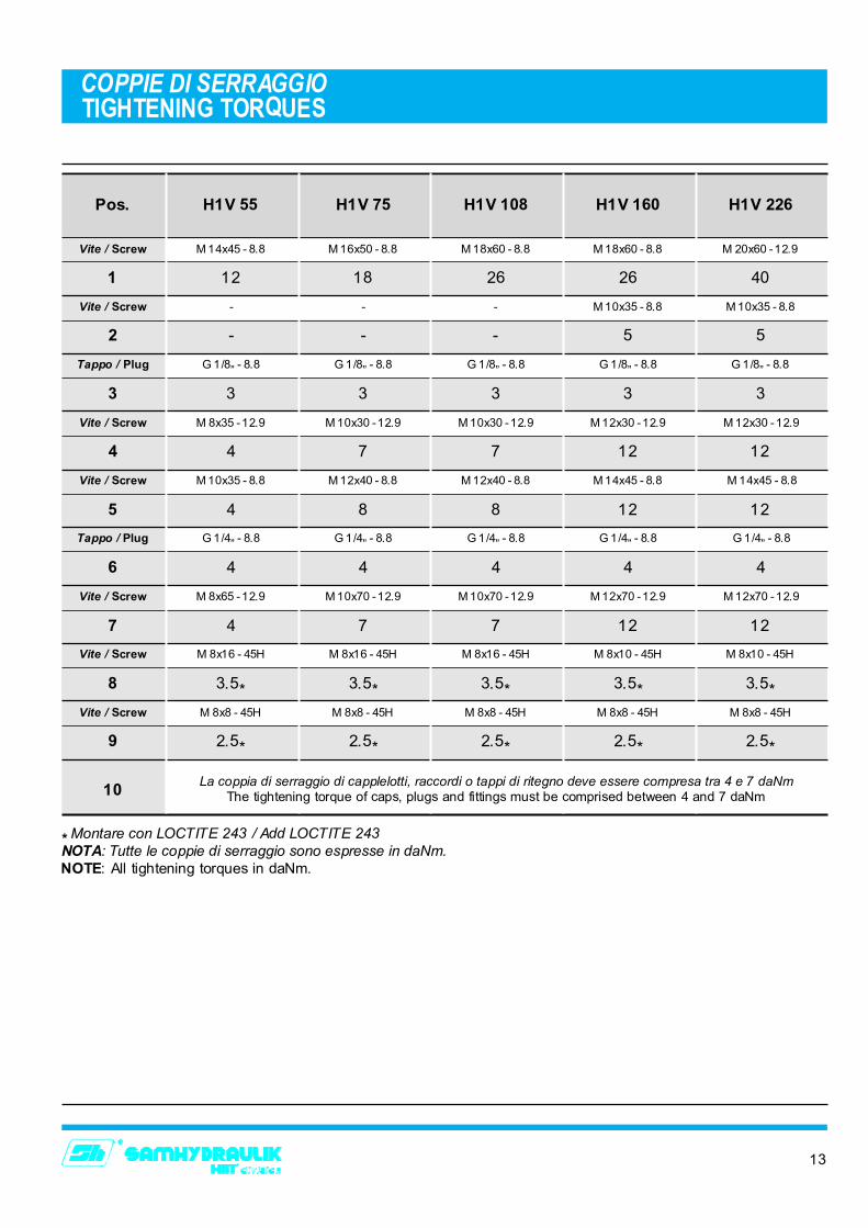
M 14x45 - 8.8
12
M 16x50 - 8.8
18
M 18x60 - 8.8
26
M 18x60 - 8.8
26
M 20x60 - 12.9
40
Vite / Screw
1
-
-
-
-
-
-
M 10x35 - 8.8
5
M 10x35 - 8.8
5
Vite / Screw
2
G 1/8� - 8.8
3
G 1/8� - 8.8
3
G 1/8� - 8.8
3
G 1/8� - 8.8
3
G 1/8� - 8.8
3
Tappo / Plug
3
M 8x35 - 12.9
4
M 10x30 - 12.9
7
M 10x30 - 12.9
7
M 12x30 - 12.9
12
M 12x30 - 12.9
12
Vite / Screw
4
M 10x35 - 8.8
4
M 12x40 - 8.8
8
M 12x40 - 8.8
8
M 14x45 - 8.8
12
M 14x45 - 8.8
12
Vite / Screw
5
G 1/4� - 8.8
4
G 1/4� - 8.8
4
G 1/4� - 8.8
4
G 1/4� - 8.8
4
G 1/4� - 8.8
4
Tappo / Plug
6
M 8x65 - 12.9
4
M 10x70 - 12.9
7
M 10x70 - 12.9
7
M 12x70 - 12.9
12
M 12x70 - 12.9
12
Vite / Screw
7
M 8x16 - 45H
3.5*
M 8x16 - 45H
3.5*
M 8x16 - 45H
3.5*
M 8x10 - 45H
3.5*
M 8x10 - 45H
3.5*
Vite / Screw
8
M 8x8 - 45H
2.5*
M 8x8 - 45H
2.5*
M 8x8 - 45H
2.5*
M 8x8 - 45H
2.5*
M 8x8 - 45H
2.5*
Vite / Screw
9
10
Pos. H1V 55 H1V 75 H1V 108 H1V 160 H1V 226
* Montare con LOCTITE 243 / Add LOCTITE 243NOTA: Tutte le coppie di serraggio sono espresse in daNm.NOTE: All tightening torques in daNm.
La coppia di serraggio di capplelotti, raccordi o tappi di ritegno deve essere compresa tra 4 e 7 daNmThe tightening torque of caps, plugs and fittings must be comprised between 4 and 7 daNm
14
COMBINAZIONI PILOTA - MOLLE - PORTAPILOTAPILOT - PILOT HOUSING - SPRINGS COMBINATIONS
15
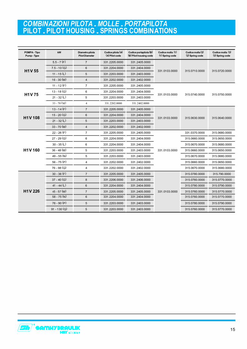
COMBINAZIONI PILOTA - MOLLE - PORTAPILOTAPILOT - PILOT HOUSING - SPRINGS COMBINATIONS
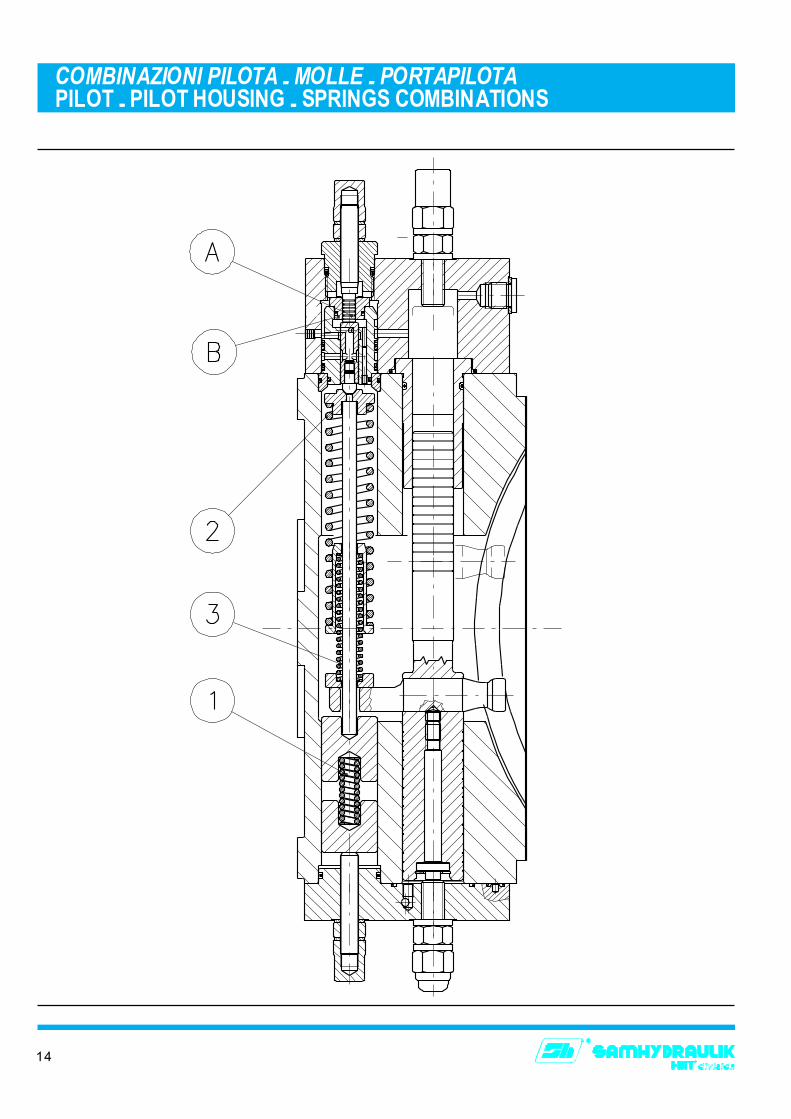
POMPA - Tipo kW Diametro pilota Codice pilota (A) Codice portapilota (B) Codice molla (1) Codice molla (2) Codice molla (3)Pump - Type Pilot Diameter (A) Pilot code (B) Pilot housing code (1) Spring code (2) Spring code (3) Spring code
5.5 - 7 (F) 7 331.2205.0000 331.2405.0000
331.0103.0000 315.0710.0000 315.0720.00007.5 - 10 (G) 6 331.2204.0000 331.2404.0000
11 - 15 (L) 5 331.2203.0000 331.2403.0000
16 - 30 (M) 4 331.2202.0000 331.2402.0000
11 - 12 (F) 7 331.2205.0000 331.2405.0000
331.0103.0000 315.0740.0000 315.0750.000013 - 18 (G) 6 331.2204.0000 331.2404.0000
21 - 32 (L) 5 331.2203.0000 331.2403.0000
33 - 70 (M) 4 331.2202.0000 331.2402.0000
13 - 14 (F) 7 331.2205.0000 331.2405.0000
331.0103.0000 315.0630.0000 315.0640.000015 - 20 (G) 6 331.2204.0000 331.2404.0000
21 - 32 (L) 5 331.2203.0000 331.2403.0000
33 - 70 (M) 4 331.2202.0000 331.2402.0000
30 - 36 (F) 7 331.2205.0000 331.2405.0000 315.0780.0000 315.790.0000
22 - 26 (F) 7 331.2205.0000 331.2405.0000 331.0370.0000 315.0680.0000
27 - 29 (G) 6 331.2204.0000 331.2404.0000 315.0660.0000 315.0650.0000
30 - 35 (L) 6 331.2204.0000 331.2404.0000 315.0670.0000 315.0680.0000
36 - 48 (M) 5 331.2203.0000 331.2403.0000 331.0103.0000 315.0660.0000 315.0650.0000
49 - 55 (N) 5 331.2203.0000 331.2403.0000 315.0670.0000 315.0680.0000
56 - 75 (P) 4 331.2202.0000 331.2402.0000 315.0660.0000 315.0650.0000
76 - 98 (Q) 4 331.2202.0000 331.2402.0000 315.0670.0000 315.0680.0000
37 - 40 (G) 8 331.2206.0000 331.2406.0000 315.0760.0000 315.0770.0000
41 - 44 (L) 6 331.2204.0000 331.2404.0000 315.0780.0000 315.0790.0000
45 - 57 (M) 7 331.2205.0000 331.2405.0000 331.0103.0000 315.0760.0000 315.0770.0000
58 - 75 (N) 6 331.2204.0000 331.2404.0000 315.0760.0000 315.0770.0000
76 - 90 (P) 5 331.2203.0000 331.2403.0000 315.0780.0000 315.0790.0000
91 - 130 (Q) 5 331.2203.0000 331.2403.0000 315.0760.0000 315.0770.0000
H1V 55
H1V 75
H1V 108
H1V 160
H1V 226
S.A.M. HYDRAULIK S.p.A.Via Moscova, 10 - 42100 REGGIO EMILIA (Italy)Tel. +39 (0)522 270511 - Fax +39 (0)522 270460
E-mail: [email protected]://www.samhydraulik.com
Distribuito da:Represented by:
CMU.0997.A000