LIA - LISA - hornbach.de · A+B + n curve = 4 m max. ... o “DIN 18895”. - La lunghezza totale...
32
Il libretto istruzioni è parte integrante del prodotto. - The instruction manual is an integral part of the product. - Le mode d’emploi est partie intégrante du produit. - Die Anleitung ist Bestandteil des Produktes. Deze handleiding maakt een wezenlijk deel uit van het product. - El manual de instrucciones forma parte integrante del producto. - O Manual de Instruções faz parte integrante do produto. Set canalizzazione Ducting set Set de canalisation Kanalisations-Set Kanaliseringskit Kit de canalización Conjunto de canalização LIA - LISA ISTRUZIONI PER L’INSTALLATORE INSTALLER INSTRUCTIONS INSTRUCTIONS POUR L’INSTALLATEUR INSTALLATIONSANLEITUNG INSTRUCTIES VOOR DE MONTEUR INSTRUCCIONES PARA EL INSTALADOR INSTRUÇÕES DE INSTALAÇÃO Italiano English Français Nederlands Deutsch Español Português
Transcript of LIA - LISA - hornbach.de · A+B + n curve = 4 m max. ... o “DIN 18895”. - La lunghezza totale...

Il lib
retto
istru
zioni
è p
arte
inte
gran
te d
el p
rodo
tto. -
The
inst
ruct
ion
man
ual i
s an
inte
gral
par
t of t
he p
rodu
ct. -
Le
mod
e d’
empl
oi e
st p
artie
inté
gran
te d
u pr
odui
t. - D
ie A
nlei
tung
ist B
esta
ndte
il de
s Pr
oduk
tes.
Deze
han
dlei
ding
maa
kt e
en w
ezen
lijk
deel
uit
van
het p
rodu
ct. -
El m
anua
l de
inst
rucc
ione
s fo
rma
parte
inte
gran
te d
el p
rodu
cto.
- O
Man
ual d
e In
stru
ções
faz
parte
inte
gran
te d
o pr
odut
o.
Set canalizzazioneDucting set
Set de canalisationKanalisations-SetKanaliseringskit
Kit de canalizaciónConjunto de canalização
LIA - LISA
ISTRUZIONI PER L’INSTALLATOREINSTALLER INSTRUCTIONS
INSTRUCTIONS POUR L’INSTALLATEURINSTALLATIONSANLEITUNG
INSTRUCTIES VOOR DE MONTEURINSTRUCCIONES PARA EL INSTALADOR
INSTRUÇÕES DE INSTALAÇÃO
Italia
noEn
glis
hFr
ança
isNe
derla
nds
Deut
sch
Espa
ñol
Port
uguê
s

ITALIANO ENGLISH FRANÇAIS DEUTSCHNr. Descrizione Description Description Beschreibung Qty.1 Ventilatore Fan Ventilateur Ventilator 12 Chiusura superiore stufa Top stove seal Fermeture supérieure poêle Obere Abdeckung des Ofens 13 Protezione Protection Protection Schutzabdeckung 14 Cavo cablato Cable Câble de connexion Verkabeltes Kabel 15 Vite M5 M5 screw Vis M5 Schraube M5 126 Laccio con aggancio Latch fastener Attache omega encliquetable Schlinge mit Haken 67 Fascetta Clamp Collier de serrage Kabelbinder 58 Vite M5x35 M5x35 Screw Vis M5x35 Schraube M5x35 19 Morsetto ponte Clamp Borne à boucle Brückenklemme 1
NEDERLANDS ESPAÑOL PORTUGUÊSNr. Beschrijving Descripción Descrição Qty.1 Ventilator Ventilador Ventilador 1
2 Afsluiting aan de bovenkant van de kachel Cierre superior de la estufa Fecho superior da salamandra 1
3 Bescherming Protección Proteção 14 Kabel Cable cableado Cabo cablado 15 Schroef M5 Tornillo M5 Parafuso M5 126 Haak met koppeling Lazo con enganche Cordão com engate 67 Klemmetje Abrazadera Abraçadeira 58 Schroef M5x35 Tornillo M5x35 Parafuso M5x35 19 Brückenklemme Borne puente Terminal ponte 1
8
5
9
6
7
x 12
x 6
x 5
x 1
x 1
3
1
2
4
2
DT2034059-01
H07031720 / DT2002253 – 01
Gentile Cliente,La ringraziamo per aver preferito uno dei nostri prodotti, frutto di lunga esperienza e di una continua ricerca per un prodotto superiore in termini di sicurezza, affidabilità e prestazioni.In questo manuale troverà tutte le informazioni ed i consigli utili per poter utilizzare il suo prodotto nel massimo della sicurezza ed efficienza.
INDICAZIONI IMPORTANTI• Questo libretto istruzioni è stato redatto dal costruttore e costituisce
parte integrante del prodotto.Le informazioni in esso contenute sono indirizzate all’acquirente, e a tutte quelle persone che a vario titolo concorrono all’installazione, all’uso e alla manutenzione del prodotto.
• Leggete con attenzione le istruzioni e le informazioni tecniche contenute in questo manuale, prima di procedere all’installazione, all’utilizzo e a qualsiasi intervento sul prodotto.
• L’osservanza delle indicazioni contenute nel presente libretto istruzioni garantisce la sicurezza alle persone e cose; assicura l’economia di esercizio ed una più lunga durata di funzionamento.
• Il costruttore declina ogni responsabilità per danni causati dalla inosservanza alle norme di installazione uso e manutenzione indicate nel libretto di istruzioni, per modifiche del prodotto non autorizzate o ricambi non originali.
• L’attenta progettazione e l’analisi dei rischi fatti dal costruttore hanno permesso la realizzazione di un prodotto sicuro; tuttavia prima di effettuare qualsiasi operazione, si raccomanda di attenersi scrupolosamente alle istruzioni riportate nel seguente documento, e di tenerlo sempre a disposizione.
• L’installazione e l’utilizzo del prodotto devono essere fatti in conformità con le istruzioni del fabbricante, e nel rispetto delle normative europee, nazionali e dei regolamenti locali.
• L’installazione, il collegamento elettrico, la verifica del funzionamento, la manutenzione e le riparazioni, sono operazioni che devono essere eseguite esclusivamente da personale qualificato, autorizzato e in possesso di adeguata conoscenza del prodotto.
• Le immagini riportate nel presente libretto sono a titolo esplicativo e talvolta possono non rappresentare esattamente il prodotto.
Per i termini, limiti ed esclusioni fare riferimento al certificato di garanzia allegato al prodotto.Il costruttore nell’intento di perseguire una politica di costante sviluppo e rinnovamento del prodotto può apportare, senza preavviso alcuno, le modifiche che riterrà opportune.Questo documento è di proprietà del costruttore; non può essere divulgato totalmente o in parte a terzi senza autorizzazione scritta del costruttore. Il costruttore si riserva i diritti a rigore di legge.
ESEMPI DI ALLACCIAMENTO TUBI FLESSIBILIIl set canalizzazione aria calda permette di prelevare il flusso d’aria nella parte superiore della stufa e canalizzarlo in altri ambienti con tubi flessibili Ø 75 mm.Forniamo alcuni esempi a titolo dimostrativo di canalizzazione dell’aria calda per il riscaldamento di locali attigui.
a L’ottimale rendimento della stufa si ottiene con tubi flessibili Ø 75. La lunghezza massima della canalizzazione dipende dalla configurazione adottata (vedi in seguito).
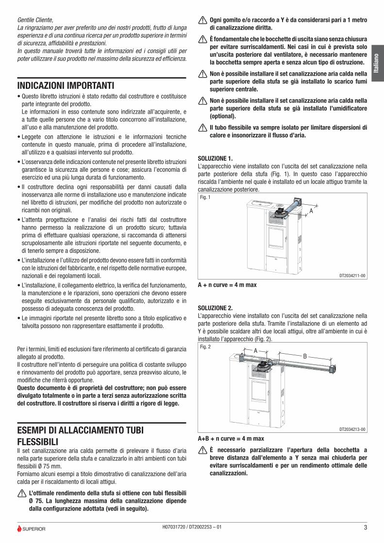
a Ogni gomito e/o raccordo a Y è da considerarsi pari a 1 metro di canalizzazione diritta.
a È fondamentale che le bocchette di uscita siano senza chiusura per evitare surriscaldamenti. Nei casi in cui è prevista solo un’uscita posteriore dal ventilatore, è necessario mantenere la bocchetta sempre aperta e senza alcun tipo di ostruzione.
a Non è possibile installare il set canalizzazione aria calda nella parte superiore della stufa se già installato lo scarico fumi superiore centrale.
a Non è possibile installare il set canalizzazione aria calda nella parte superiore della stufa se già installato l’umidificatore (optional).
a Il tubo flessibile va sempre isolato per limitare dispersioni di calore e insonorizzare il flusso d’aria.
SOLUZIONE 1.L’apparecchio viene installato con l’uscita del set canalizzazione nella parte posteriore della stufa (Fig. 1). In questo caso l’apparecchio riscalda l’ambiente nel quale è installato ed un locale attiguo tramite la canalizzazione posteriore.
A
Fig. 1
DT2034211-00
A + n curve = 4 m max
SOLUZIONE 2.L’apparecchio viene installato con l’uscita del set canalizzazione nella parte posteriore della stufa. Tramite l’installazione di un elemento ad Y è possibile scaldare altri due locali attigui, oltre all’ambiente in cui è installato l’apparecchio (Fig. 2).
AB
Fig. 2
DT2034213-00
A+B + n curve = 4 m max
a È necessario parzializzare l’apertura della bocchetta a breve distanza dall’elemento a Y senza mai chiuderla per evitare surriscaldamenti e per un rendimento ottimale delle canalizzazioni.
3
Italia
no
H07031720 / DT2002253 – 01

SOLUZIONE 3.L’apparecchio viene installato con l’uscita del set canalizzazione nella parte posteriore della stufa (Fig. 3). In questo caso l’apparecchio riscalda l’ambiente nel quale è installato ed un locale attiguo tramite la canalizzazione superiore.
A
BFig. 3
DT2034214-00
A+B + n curve = 4 m max.
SOLUZIONE 4.L’apparecchio viene installato con l’uscita del set canalizzazione nella parte laterale destra (Fig. 4). È possibile installare un elemento ad Y per scaldare due ambienti attigui, oltre all’ambiente in cui è installato l’apparecchio.
A
Fig. 4
A+B + n curve = 4 m max.
Canalizzazione a parete.Per una distribuzione efficace del calore canalizzato è obbligatorio: - Rivestire il tubo con guaina isolante dello spessore di 2 cm (es. fibra minerale, fibra ceramica, fibra di roccia) in modo da limitare le dispersioni e garantire una temperatura dell’aria sufficientemente alta.
- La guaina isolante deve avere peso specifico uguale o superiore a 50 kg/m³ con una temperatura limite d’utilizzo di almeno 250°C. Conducibilità termica (100°C) ≤ 0,050 W/mK.
- Per l’isolamento termico è ammesso materiale codificato “AGI Q132” o “DIN 18895”.
- La lunghezza totale massima del tubo flessibile in uscita dal ventilatore non deve superare i 4 metri.
a Se il materiale isolante non è all’interno della pavimentazione o di pareti è necessario fissarlo sulla superficie con dei punti di ancoraggio ogni 30 cm.
A lato alcuni esempi di sistemazione del tubo flessibile a parete (Fig. 5-6).Fig. 5 Fig. 6
Zona d’irraggiamento bocchetta uscita aria calda.Attorno alla bocchetta di uscita aria calda è necessario mantenere una zona all’interno della quale è vietata la presenza di oggetti infiammabili (mobili, tappeti, tende, ecc.) o sensibili al calore (legno, plastica, ecc.).Nella figura 7 sono riportate le misure in mm della zona di sicurezza, tale zona comprende i 600 mm considerati partendo dal bordo superiore della bocchetta.
R600
600
600600
BOCCHETTA USCITA ARIA CALDAFig. 7
DT2030172-00
a In presenza di pavimento infiammabile, le bocchette di uscita dell’aria calda devono essere poste ad una distanza di almeno 200 mm dal pavimento.
INSTALLAZIONE a Se installato il SET CANALIZZAZIONE ARIA CALDA non è possibile attivare la MODALITÀ NOTTE.
MODELLO LIA. - Rimuovere il rivestimento seguendo le istruzioni riportate nel paragrafo “RIMOZIONE RIVESTIMENTO” del libretto istruzioni allegato al prodotto.
MODELLO LISA. - Rimuovere il rivestimento in ceramica seguendo le istruzioni indicate nel capitolo “INSTALLAZIONE” del libretto istruzioni del rivestimento.
4
Italia
no
H07031720 / DT2002253 – 01

INSTALLAZIONE CON USCITA POSTERIORE. - Con l’ausilio di una pinza togliere il semitrancio (B) posto sul pannello posteriore della stufa. (Fig. 8)
C
B
GFig. 8
DT2034063-00
INSTALLAZIONE CON USCITA LATERALE. - Togliere il semitrancio sul pannello laterale (C). (Fig. 9)
Procedere come segue: - Con l’ausilio di una pinza togliere i due supporti umidificatore (G). (Fig. 8)
a I due supporti (G) sono a perdere.
- Fissare la chiusura superiore (2) con 4 viti M5 in dotazione. Posizionare le frecce presenti nel pezzo come rappresentato a lato. (Fig. 9)
2Fig. 9
DT2034064-00
USCITA POSTERIORE (D). - Fissare il ventilatore (1) con 3 viti M5 in dotazione. (Fig. 10) - Collegare l’uscita del ventilatore con il tubo flessibile Ø 75 mm non fornito in dotazione.
USCITA LATERALE DESTRA (E). - Fissare il ventilatore (1) con 3 viti M5 in dotazione. (Fig. 10) - Collegare l’uscita del ventilatore con il tubo flessibile Ø 75 mm non fornito in dotazione.
D
E
1
1
Fig. 10
DT2034065-00
- Piegare con una pinza la linguetta laterale presente nella protezione (3) come indicato a lato. (Fig. 11)
3Fig. 11
DT2034066-00
a Per installazione con uscita laterale destra (E) togliere, con l’ausilio di una pinza, il semitrancio (F) che si trova nella parte destra della protezione (3).
- Far passare il cavo cablato (4) attraverso la fessura nella protezione (3) e collegare i terminali del cavo cablato sul ventilatore (1) come indicato nello schema elettrico della stufa. (Fig. 12)
1 3
4
Fig. 12
DT2034067-00
- Fissare la protezione (3) con le viti M5 in dotazione. (Fig. 13)
3Fig. 13
DT2034068-00
5
Italia
no
H07031720 / DT2002253 – 01
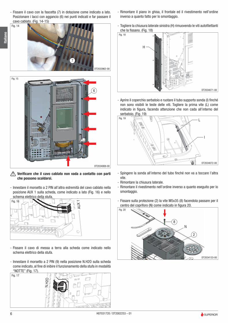
- Fissare il cavo con la fascetta (7) in dotazione come indicato a lato. Posizionare i lacci con aggancio (6) nei punti indicati e far passare il cavo cablato. (Fig. 14-15)
7
Fig. 14
DT2033962-00
6
Fig. 15
DT2034069-00
a Verificare che il cavo cablato non vada a contatto con parti che possono scaldarsi.
- Innestare il morsetto a 2 PIN all’altra estremità del cavo cablato nella posizione AUX 1 sulla scheda, come indicato a lato (Fig. 16) e nello schema elettrico della stufa.
AU
X 1Fig. 16
- Fissare il cavo di messa a terra alla scheda come indicato nello schema elettrico della stufa.
- Innestare il morsetto a 2 PIN (9) nella posizione N.H2O sulla scheda come indicato, al fine di inibire il funzionamento della stufa in modalità “NOTTE” (Fig. 17).
N.H
2O
Fig. 17
- Rimontare il piano in ghisa, il frontale ed il rivestimento nell’ordine inverso a quanto fatto per lo smontaggio.
- Togliere la chiusura laterale sinistra (H) rimuovendo le viti autofilettanti che la fissano. (Fig. 18)
H
Fig. 18
DT2034071-00
- Aprire il coperchio serbatoio e ruotare il tubo supporto sonda (I) finché non sono visibili le teste delle viti. Togliere la prima vite (L) come indicato in figura, facendo attenzione che non cada all’interno del serbatoio. (Fig. 19)
L
I
Fig. 19
DT2034072-00
- Spingere la sonda all’interno del tubo finché non va a toccare l’altra vite.
- Rimontare la chiusura laterale. - Rimontare il rivestimento nell’ordine inverso a quanto eseguito per lo smontaggio.
- Fissare sulla protezione (2) la vite M5x35 (8) facendola passare per il centro del copriforo (N) come indicato in figura 20.
8
2
N
Fig. 20
DT2034133-00
6
Italia
no
H07031720 / DT2002253 – 01

Dear Customer,We thank you for having chosen one of our products, the fruit of extensive and continuous research for a superior product in terms of safety, reliability and performance.In this manual you will find all the information and advice you need to use your product as safely and efficiently as possible.
ESSENTIAL INSTRUCTIONS• This instruction booklet has been prepared by the manufacturer and
is an integral part of the product.Its instructions are intended for the buyer and all individuals involved in the installation, use and maintenance of the product.
• Read the instructions and the technical information contained in this manual carefully, before proceeding with installation, use or any repairs.
• Compliance with the instructions in this booklet guarantees the safety of persons and of property; it also ensures more efficient operation and an increased lifespan.
• The manufacturer declines all responsibility for damage caused by failure to observe the installation, use and maintenance instructions in this manual, for unauthorized product modifications or for use of unoriginal aftermarket parts.
• Careful planning and risk analysis made by the manufacturer have allowed for a safe product; however, before performing any operation, it is recommended to carefully follow the instructions in this document and keep it available at all times.
• The installation and use of the product must be made in accordance with the manufacturer’s instructions and in compliance with European, national and local regulations.
• The installation, electrical connection, operational check, maintenance and repairs are operations that must be performed by qualified and licensed technicians that have appropriate knowledge of the product.
• The images shown in this manual are for explanatory purposes and at times may not accurately depict the product.
For the restrictions, limitations and exclusions please refer to the warranty included with the product.In line with its policy of constant product improvement and renewal, the manufacturer may make changes without notice.This document is the property of the manufacturer; no part of it may be disclosed to third parties without the written permission thereof. All rights reserved by the manufacturer.
EXAMPLES OF FLEXIBLE PIPE CONNECTIONThe hot air ducting set draws airflow from the top part of the stove and channels it to other rooms with 0.75 mm flexible pipes. Below are some examples on how hot air is channelled into adjacent rooms.
a Top stove performance is obtained by using Ø 75 flexible pipes. Maximum ducting length depends on the configuration installed (see later in manual).
a Every bend and/or Y connector is comparable to 1 metre of straight ducting.
a The outlets must not be closed in order to avoid overheating. The outlet must always be kept open and free of clogs in cases where there is only one rear outlet from the fan.
a The hot air ducting set cannot be installed on the top part of the stove if the mid-top smoke flue is already installed.
a The hot air ducting set cannot be installed on the top part of the stove if the humidifier is already installed (optional).
a The flexible pipe must always be insulated to avoid heat dispersion and provide sound cladding for the air flow.
SOLUTION 1.The appliance is installed with the ducting set output at the rear of the stove (Fig. 1). In this case, the appliance heats the environment where it is installed as well as the adjacent room via the rear ducting.
A
Fig. 1
DT2034211-00
A + n bends = 4 m max
SOLUTION 2.The appliance is installed with the ducting set output at the rear of the stove. Installation of a Y connector makes it possible to heat two other adjacent rooms aside from the room of installation (Fig. 2).
AB
Fig. 2
DT2034213-00
A+B + n bends = 4 m max
a Outlet aperture must be partialised at short distance from the Y coupling without ever closing it in order to avoid overheating and achieve optimal ducting yield.
7
Engl
ish
H07031720 / DT2002253 – 01

SOLUTION 3.The appliance is installed with the ducting set output at the rear of the stove (Fig. 3). In this case, the appliance heats the environment where it is installed as well as the adjacent room via the top ducting.
A
BFig. 3
DT2034214-00
A+B + n bends = 4 m max
SOLUTION 4.The stove is installed with the ducting set output on the right side (Fig. 4). A Y connector can be installed to heat to adjacent rooms as well as the room that contains the stove.
A
Fig. 4
A+B + no. bends = 4 m max.
Wall ducting.For effective channelled heat distribution, you must: - Coat the pipe with insulating sheath 2 cm thick (e.g. mineral fibre, ceramic fibre, rock fibre) in order to limit dispersions and to ensure an adequately high air temperature.
- The insulating sheath must have a specific weight equal to or greater than 50 kg/m³ with a minimum operational temperature limit of at least 250°C. Thermal conductivity (100°C) ≤ 0.050 W/mK.
- The thermal insulation materials must have “AGI Q132” or “DIN 18895” labels.
- The total maximum length of the fan outflow flexible pipe must not exceed 4 metres.
a If the insulation material does not form part of flooring or walls, it will be necessary to fix it to the surface using fixing points spaced out at 30 cm intervals.
Opposite are some flexible pipe wall arrangement examples (Fig. 5-6).Fig. 5 Fig. 6
Hot air outlet heating areaAn area where the presence of flammable objects (furniture, carpets, curtains, etc.) or those affected by heat (wood, plastic,...) are forbidden is to be provided around the hot air outlet.Figure 7 displays the measurements relative to the safety area; this area includes the 600 mm taken into account starting at the upper edge of the outlet.
R600
600
600600
HOT AIR OUTLET VENTFig. 7
DT2030172-00
a Where there is flammable flooring, the hot air outlets must be placed at a distance of at least 200 mm from the floor.
INSTALLATION a NIGHT MODE cannot be activated if the HOT AIR DUCTING SET has been installed.
LIA MODEL. - Remove the casing by following the instructions in the section “CASING REMOVAL” of the instruction booklet included with the product.
LISA MODEL. - Remove the ceramic casing by following the instructions in the chapter “INSTALLATION” of the casing instruction booklet.
8
Engl
ish
H07031720 / DT2002253 – 01

INSTALLATION WITH REAR OUTLET - Use a set of pliers to remove the knockout (B) on the rear panel of the stove. (Fig. 8)
C
B
GFig. 8
DT2034063-00
INSTALLATION WITH SIDE OUTLET. - Remove the knockout on the side panel (C). (Fig. 8)
Proceed as follows: - Use a set of pliers to remove the two air humidifier supports (G). (Fig. 8)
a The two supports (G) are disposable.
- Fix the top closure (2) with the 4 x M5 screws supplied. Face the piece arrows as shown opposite. (Fig. 9)
2Fig. 9
DT2034064-00
REAR OUTLET (D). - Fix the fan (1) with the 3 x M5 screws supplied. (Fig. 11) - Connect the fan outlet with the Ø 75 mm flexible pipe that is not included with the supply.
RIGHT SIDE OUTLET (E). - Fix the fan (1) with the 3 x M5 screws supplied. (Fig. 10) - Connect the fan outlet with the Ø 75 mm flexible pipe that is not included with the supply.
D
E
1
1
Fig. 10
DT2034065-00
- Use a set of pliers to bend the side tab on the guard (3) as indicated opposite. (Fig. 11)
3Fig. 11
DT2034066-00
a For installation with right side outlet (E), use a set of pliers to remove the knockout (F) on the right side of the guard (3).
- Thread the cable (4) through the guard (3) hole and connect its terminals to the fan (1) as shown in the stove wiring diagram. (Fig. 12)
1 3
4
Fig. 12
DT2034067-00
- Fix the guard (3) with the M5 screws supplied. (Fig. 13)
3Fig. 13
DT2034068-00
9
Engl
ish
H07031720 / DT2002253 – 01
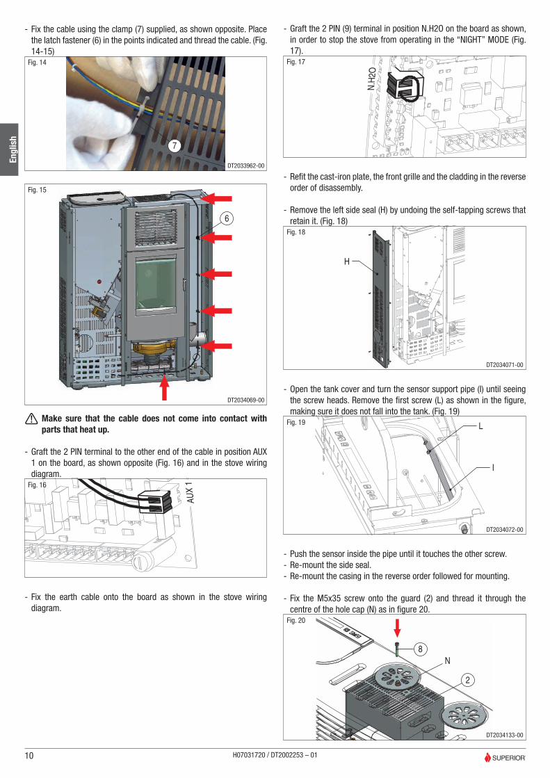
- Fix the cable using the clamp (7) supplied, as shown opposite. Place the latch fastener (6) in the points indicated and thread the cable. (Fig. 14-15)
7
Fig. 14
DT2033962-00
6
Fig. 15
DT2034069-00
a Make sure that the cable does not come into contact with parts that heat up.
- Graft the 2 PIN terminal to the other end of the cable in position AUX 1 on the board, as shown opposite (Fig. 16) and in the stove wiring diagram.
AU
X 1Fig. 16
- Fix the earth cable onto the board as shown in the stove wiring diagram.
- Graft the 2 PIN (9) terminal in position N.H2O on the board as shown, in order to stop the stove from operating in the “NIGHT” MODE (Fig. 17).
N.H
2O
Fig. 17
- Refit the cast-iron plate, the front grille and the cladding in the reverse order of disassembly.
- Remove the left side seal (H) by undoing the self-tapping screws that retain it. (Fig. 18)
H
Fig. 18
DT2034071-00
- Open the tank cover and turn the sensor support pipe (I) until seeing the screw heads. Remove the first screw (L) as shown in the figure, making sure it does not fall into the tank. (Fig. 19)
L
I
Fig. 19
DT2034072-00
- Push the sensor inside the pipe until it touches the other screw. - Re-mount the side seal. - Re-mount the casing in the reverse order followed for mounting.
- Fix the M5x35 screw onto the guard (2) and thread it through the centre of the hole cap (N) as in figure 20.
8
2
N
Fig. 20
DT2034133-00
10
Engl
ish
H07031720 / DT2002253 – 01

Cher Client,Nous vous remercions d’avoir choisi l’un de nos produits, fruit d’une longue expérience et d’une recherche continue afin d’obtenir un produit supérieur en matière de sécurité, fiabilité et performances.Dans ce manuel, vous trouverez toutes les informations et les conseils nécessaires pour utiliser votre produit en toute sécurité et avec la meilleure efficacité.
INDICATIONS IMPORTANTES• Ce mode d’emploi a été rédigé par le fabricant et constitue partie
intégrante du produit.Les informations y étant contenues s’adressent à l’acheteur et à toutes les personnes chargées de l’installation, l’utilisation et l’entretien du produit.
• Lisez avec attention les instructions et les informations techniques contenues dans ce manuel, avant de procéder à l’installation,à l’utilisation et à toute intervention sur le produit.
• Le respect des indications contenues dans le présent mode d’emploi garantit la sécurité des personnes et des choses ; il assure une économie d’exercice et une plus longue durée de fonctionnement.
• Le fabricant décline toute responsabilité pour les dommages causés par le non-respect des normes d’installation, d’utilisation et d’entretien indiquées dans le mode d’emploi, par des modifications du produit non autorisées ou par des pièces de rechange autres que celles d’origine.
• La minutieuse conception et l’analyse des risques effectuées par le constructeur ont permis la réalisation d’un produit fiable ; il est toutefois conseillé, avant d’effectuer toute opération, de suivre scrupuleusement les instructions indiquées dans ce document et de l’avoir toujours à disposition.
• L’installation et l’utilisation du produit doivent être réalisées conformément aux instructions du fabricant, et dans le respect des normes européennes, nationales et des règlements locaux.
• L’installation, le branchement électrique, la vérification du fonctionnement, l’entretien et les réparations, sont des opérations qui doivent être effectuées exclusivement par un personnel qualifié, autorisé et possédant une connaissance adaptée du produit.
• Les images présentes dans ce livret sont à titre indicatif et ne représentent pas toujours avec exactitude le produit proposé.
Pour les délais, limites et exclusions, consultez le certificat de garantie joint au produit.Afin de poursuivre une politique de développement et de renouvellement constants du produit, le fabricant peut apporter, sans aucun préavis, les modifications qu’il considèrera nécessaires.Ce document appartient au fabricant et ne peut être divulgué totalement ou en partie à des tiers sans son autorisation écrite. Le fabricant se réserve tous les droits conformément à la loi.
EXEMPLES DE RACCORDEMENT DES TUYAUX FLEXIBLESLe set de canalisation d’air chaud permet de prélever le flux de l’air dans la partie haute du poêle et de le canaliser dans d’autres pièces au moyen de tuyaux flexibles de Ø 75 mm.Nous vous proposons quelques exemples à titre illustratif de canalisation de l’air chaud pour le chauffage de lieux contigus.
a Le meilleur rendement du poêle s’obtient avec des tuyaux de
75 mm de diamètre. La longueur maximum du gainage dépend de la configuration adoptée (voir ci-dessous).
a Chaque coude et/ou raccord en Y doit être considéré égal à 1 mètre de gainage droit.
a Il est fondamental que les bouches de diffusion d’air soient dépourvue de volet de fermeture afin d’éviter tout risque de surchauffe. Si une seule sortie est prévue à l’arrière du ventilateur , il est nécessaire de maintenir la bouche de diffusion toujours ouverte, sans qu’elle ne soit obstruée.
a Il n’est pas possible d’installer le set de canalisation d’air chaud dans la partie haute du poêle si le conduit d’évacuation central supérieur de la fumée est déjà installé.
a Il n’est pas possible d’installer le set de canalisation d’air chaud dans la partie haute du poêle si l’humidificateur est déjà installé (en option).
a Le tuyau flexible doit toujours être isolé pour limiter les déperditions de chaleur et insonoriser le flux d’air.
SOLUTION 1.L’appareil est installé avec la sortie du set de canalisation situé dans la partie arrière du poêle (Fig. 1). Dans ce cas, l’appareil réchauffe la pièce dans laquelle il est installé et le local contigu à travers la canalisation arrière.
A
Fig. 1
DT2034211-00
A + n° coudes = 4 m max
SOLUTION 2.L’appareil est installé avec la sortie du set de canalisation situé à l’arrière du poêle. En installant un élément en Y, il est possible de chauffer deux autres locaux contigus, outre à la pièce dans laquelle se trouve l’appareil (Fig. 2).
AB
Fig. 2
DT2034213-00
A+B + n° coudes = 4 m max
a Il est nécessaire réduire l’ouverture de la bouche de diffusion située à une courte distance de l’élément en Y, sans pour autant ne jamais la fermer afin d’éviter des surchauffes et de favoriser un rendement optimal des canalisations.
11
Fran
çais
H07031720 / DT2002253 – 01

SOLUTION 3.L’appareil est installé avec la sortie du set de canalisation dans la partie arrière du poêle (Fig. 3). Dans ce cas, l’appareil réchauffe la pièce dans la quelle il est installé et le local contigu à travers la canalisation supérieure.
A
BFig. 3
DT2034214-00
A+B + n° coudes = 4 m max
SOLUTION 4.L’appareil est installé avec la sortie du set de canalisation situé dans la partie latérale droite (Fig. 4). Il est possible d’installer un élément en Y pour chauffer deux pièces contiguës, outre à celle dans laquelle se trouve l’appareil.
A
Fig. 4
A+B + n° coudes = 4 m max.
Canalisation murale.Pour une distribution efficace de la chaleur canalisée, il faut : - Rhabiller le tuyau avec un manchon isolant d’une épaisseur de 2 cm (ex. fibre minérale, fibre céramique, fibre de roche) de façon à limiter les déperditions de chaleur et garantir une température de l’air suffisamment élevée.
- Le manchon isolant doit avoir un poids spécifique égal ou supérieur à 50 kg/m³ et un seuil de tolérance thermique d’au moins 250°C. Conductibilité thermique (100°C) ≤ 0,050 W/mK.
- Pour l’isolation thermique, le matériel portant le code « AGI Q132 » ou « DIN 18895 » est admissible.
- La longueur totale maximale du tuyau flexible depuis l’orifice de sortie au ventilateur ne doit pas être supérieure à 4 mètres.
a Si l’isolant thermique ne se trouve pas dans le sol ou dans les murs, il est nécessaire de le fixer sur la surface avec des points de fixation tous les 30 cm.
Ci-après quelques exemples de mise en place du tuyau flexible dans la paroi (Fig. 5-6).Fig. 5 Fig. 6
Zone de rayonnement de la bouche de diffusion d’air chaud.Il convient de ménager autour de la bouche de diffusion d’air chaud une zone de sécurité à l’intérieur de laquelle aucun objet inflammable (meubles, tapis, rideaux, etc.) ou matériau sensible à la chaleur (bois, plastique, etc.) ne doit se trouver.Sur la figure 7 sont indiquées les dimensions en mm de cette zone de sécurité ; celle-ci s’étend sur 600 mm à partir du bord supérieur de la bouche de diffusion.
R600
600
600600
BOUCHE DE DIFFUSION AIR CHAUDFig. 7
DT2030172-00
a En cas de sol inflammable, les bouches de diffusion d’air chaud doivent être situées à une distance minimale de 200 mm du sol.
INSTALLATION a Si vous installez le SET CANALISATION DE L’AIR CHAUD il ne vous sera pas possible d’activer la fonction MODE NUIT.
MODÈLE LIA. - Retirez le revêtement en suivant les instructions fournies au paragraphe « RETRAIT DU REVÊTEMENT » du mode d’emploi joint au produit.
MODÈLE LISA. - Retirez le revêtement en céramique en suivant les instructions indiquées au chapitre « INSTALLATION » du mode d’emploi du revêtement.
12
Fran
çais
H07031720 / DT2002253 – 01

INSTALLATION AVEC SORTIE ARRIÈRE - À l’aide d’une pince, désoperculez le trou central (B) situé sur le panneau arrière du poêle. (Fig. 8)
C
B
GFig. 8
DT2034063-00
INSTALLATION AVEC SORTIE LATÉRALE - Désoperculez le trou sur le panneau latéral (C). (Fig. 8)
Procédez ainsi : - À l’aide d’une pince, retirez les deux supports prévus pour l’humidificateur (G). (Fig. 8)
a Les deux supports (G) peuvent être éliminés.
- Fixez la fermeture supérieure (2) avec les 4 vis M5 fournies. Positionnez les flèches présentes sur la pièce comme l’indique la figure ci-contre. (Fig. 9)
2Fig. 9
DT2034064-00
SORTIE ARRIÈRE (D) - Fixez le ventilateur (1) avec les 3 vis M5 fournies. (Fig. 10) - Reliez la sortie du ventilateur avec le tuyau flexible Ø 75 mm non fourni.
SORTIE LATÉRALE DROITE (E) - Fixez le ventilateur (1) avec les 3 vis M5 fournies. (Fig. 10) - Reliez la sortie du ventilateur avec le tuyau flexible Ø 75 mm non fourni.
D
E
1
1
Fig. 10
DT2034065-00
- Pliez avec une pince la languette latérale présente dans la protection (3) comme il est indiqué ci-contre. (Fig. 11)
3Fig. 11
DT2034066-00
a Pour l’installation avec sortie latérale droite (E), désoperculez, à l’aide d’une pince, le trou (F) qui se trouve dans la partie droite de la protection (3).
- Faites passer le câble de connexion (4) à travers la fente de la protection (3) et reliez les embouts du câble de connexion au ventilateur (1) comme il est indiqué dans le schéma électrique du poêle. (Fig. 12)
1 3
4
Fig. 12
DT2034067-00
- Fixez la protection (3) avec les vis M5 fournies. (Fig. 13)
3Fig. 13
DT2034068-00
13
Fran
çais
H07031720 / DT2002253 – 01

- Fixez le câble avec le collier de serrage (7) fourni comme il est indiqué ci-contre. Placez les attaches oméga encliquetables (6) sur les points indiqués et faîtes passer le câble de connexion. (Fig. 14-15)
7
Fig. 14
DT2033962-00
6
Fig. 15
DT2034069-00
a Vérifiez que le câble de connexion n’entre pas en contact avec des parties qui peuvent devenir chaudes.
- Insérez la borne à 2 Broches sur l’autre extrémité du câble dans la position AUX 1 sur la carte, comme il est indiqué ci-contre (Fig. 16) et sur le schéma électrique du poêle.
AU
X 1Fig. 16
- Fixez le câble de mise à la terre à la carte comme l’indique le schéma électrique du poêle.
- Insérez la borne à 2 Broches (9) dans la position N.H20 sur la carte comme il est indiqué, afin d’inhiber le fonctionnement du poêle en modalité « NUIT » (Fig. 17).
N.H
2O
Fig. 17
- Remontez le plan en fonte, la façade et l’habillage dans le sens inverse de celui prévu pour le montage.
- Enlevez la fermeture latérale gauche (H) en retirant les vis autotaraudeuses de fixation. (Fig. 18)
H
Fig. 18
DT2034071-00
- Ouvrez le couvercle du réservoir et tournez le tube de support de la sonde (I) jusqu’à ce que les têtes des vis ne soient plus visibles. Retirez la première vis (L) comme l’indique la figure, en faisant attention qu’elle ne tombe pas à l’intérieur du réservoir. (Fig. 19)
L
I
Fig. 19
DT2034072-00
- Poussez la sonde à l’intérieur du tube jusqu’à ce qu’elle aille toucher l’autre vis.
- Remontez la fermeture latérale.
- Remontez le revêtement dans l’ordre inverse à celui suivi pour le démontage.
- Fixez sur la protection (2) la vis M5x35 (8) en la faisant passer au centre du cache-trou (N) comme il est indiqué sur la figure 20.
8
2
N
Fig. 20
DT2034133-00
14
Fran
çais
H07031720 / DT2002253 – 01

Sehr geehrte Kundin, sehr geehrter Kunde,Wir möchten uns bei Ihnen dafür bedanken, dass Sie sich für unsere Produkte entschieden haben, die aus langjähriger Erfahrung und einer kontinuierlichen Forschung im Bereich der Sicherheit, Zuverlässigkeit und Leistungsfähigkeit entstehen.In dieser Anleitung finden Sie alle Informationen sowie nützliche Hinweise für die Nutzung Ihres Produktes mit höchster Sicherheit und Effizienz.
WICHTIGE HINWEISE• Diese Anleitung wurde vom Hersteller verfasst und stellt einen wesentlichen
Bestandteil des Produktes dar.Die darin enthaltenen Informationen sind für den Käufer und alle diejenigen bestimmt, die für die Installation, den Gebrauch und die Wartung der Anleitung zuständig sind.
• Lesen Sie die enthaltenen Anweisungen und technischen Informationen aufmerksam, bevor Sie mit der Installation, dem Gebrauch und sonstigen Arbeiten am Produkt beginnen.
• Die Beachtung der Anweisungen der vorliegenden Anleitung garantiert die Sicherheit von Personen und Gegenständen; sie sichert die Wirtschaftlichkeit des Betriebs sowie eine lange Lebensdauer des Produktes.
• Der Hersteller weist jegliche Verantwortung für Schäden von sich, die durch die Nichtbeachtung der Installations-, Gebrauchs- und Wartungsanweisungen, nicht genehmigte Änderungen am Produkt oder nicht originale Ersatzteile verursacht werden.
• Die sorgfältige Planung und Analyse der Risiken durch den Hersteller haben die Herstellung eines sicheren Produktes ermöglicht; trotzdem müssen bei der Ausführung jeglicher Arbeiten strikt die Anweisungen der vorliegenden Anleitung beachtet werden und stets griffbereit sein.
• Die Installation und der Gebrauch des Produktes müssen gemäß den Anweisungen des Herstellers sowie den europäischen, nationalen und lokalen Normen und Vorschriften vorgenommen werden.
• Installation, elektrischer Anschluss, Betriebsprüfungen, Wartung und Reparaturen dürfen ausschließlich durch autorisiertes Fachpersonal durchgeführt werden, das eine ausreichende Kenntnis des Produktes besitzt.
• Die Bilder der vorliegenden Anleitung haben reinen Beispielcharakter und können unter Umständen nicht genau das Produkt darstellen.
Für die Bedingungen, Beschränkungen und Ausschlüsse verweisen wir auf die Garantiebescheinigung, die dem Produkt beiliegt.Zum Zweck der kontinuierlichen Weiterentwicklung und Erneuerung des Produktes kann der Hersteller ohne vorherige Ankündigung die Änderungen am Produkt vornehmen, die er für angemessen hält.Dieses Dokument ist Eigentum des Herstellers; seine Verbreitung und Vervielfältigung, auch in Teilen, ist ohne die schriftliche Genehmigung durch den Hersteller untersagt. Der Hersteller behält sich alle Rechte vor.
BEISPIEL FÜR DEN ANSCHLUSS DER SCHLÄUCHEDer Kanalisierungs-Set für warme Luft ermöglicht es, den Luftstrom im oberen Bereich des Ofens zu entnehmen und mithilfe eines Schlauchs Ø 75 mm in andere Räume zu leiten.Es folgen einige Beispiele, die zeigen, wie die Kanalisierung der warmen Luft für die Beheizung der Nebenräume genutzt werden kann.
a Die optimale Leistung des Ofens erhält man mit Schläuchen mit Ø 75. Die Höchstlänge der Kanalisierung hängt von der angewandten Konfiguration ab (siehe im Folgenden).
a Für jedes Eckstück bzw. Y-Element muss 1 Meter gerade Kanalisierung berücksichtigt werden.
a Es ist sehr wichtig, dass die Ausgangsöffnungen nicht verschlossen sind, um Überhitzungen zu vermeiden. In den Fällen, in denen nur der hintere Ausgang des Ventilators vorgesehen ist, muss die Öffnung immer offen und nicht verstopft sein.
a Der Kanalisations-Set für die warme Luft kann nicht im oberen Bereich des Ofens installiert werden, wenn bereits der Rauchablass oben in der Mitte installiert ist.
a Der Kanalisations-Set für die warme Luft kann nicht im oberen Bereich des Ofens installiert werden, wenn bereits der Befeuchter (Sonderzubehör) installiert ist.
a Der Schlauch muss immer isoliert werden, um Wärmeverluste zu vermeiden und den Luftstrom schallzuisolieren.
LÖSUNG 1.Der Ofen wird so installiert, dass sich der Auslass des Kanalisations-Sets im rückwärtigen Bereich des Ofens befindet (Abb. 1). In diesem Fall beheizt der Ofen den Raum, in dem er installiert ist, sowie einen Nebenraum über die rückwärtige Kanalisation.
A
Abb. 1
DT2034211-00
A + Anz. Rohrbögen = max. 4 m
LÖSUNG 2.Der Ofen wird so installiert, dass sich der Auslass des Kanalisations-Sets im rückwärtigen Bereich des Ofens befindet. Mithilfe der Installation eines Y-Elementes können neben dem Raum, in dem der Ofen installiert ist, zwei weitere angrenzende Räume beheizt werden (Abb. 2).
AB
Abb. 2
DT2034213-00
A+B + Anz. Rohrbögen = max. 4 m
a Die Öffnung in der Nähe des Y-Elements muss gedrosselt, darf aber nie ganz geschlossen werden, um eine Überhitzung zu vermeiden und eine optimale Leistungsfähigkeit der Kanäle zu garantieren.
15
Deut
sch
H07031720 / DT2002253 – 01

LÖSUNG 3.Der Ofen wird so installiert, dass sich der Auslass des Kanalisations-Sets im hinteren Bereich des Ofens befindet (Abb. 3). In diesem Fall beheizt der Ofen den Raum, in dem er installiert ist, sowie einen Nebenraum über die obere Kanalisation.
A
BAbb. 3
DT2034214-00
A+B + Anz. Rohrbögen = max. 4 m
LÖSUNG 4.Der Ofen wird so installiert, dass sich der Auslass des Kanalisations-Sets an der rechten Seite des Ofens befindet (Abb. 4). Es kann ein Y-Element installiert werden, um neben dem Raum, in dem der Ofen steht, auch zwei angrenzende Räume zu beheizen.
A
Abb. 4
A+B + Anz. Rohrbögen = max. 4.
Kanalisierung an der Wand.Für eine effiziente Verteilung der kanalisierten Wärme müssen folgende Bedingungen erfüllt sein: - Der Schlauch muss mit einer 2 cm starken Isolierhülle (z. B. Mineralfaser, Keramikfaser, Gesteinsfaser) verkleidet sein, um die Wärmestreuung zu begrenzen und eine ausreichend hohe Lufttemperatur zu garantieren.
- Die Isolierhülle muss eine relative Dichte von mindestens 50 kg/m³ und eine Höchsttemperatur für die Nutzung von mindestens 250°C haben. Wärmeleitfähigkeit (100°C) ≤ 0,050 W/mK.
- Für die Wärmeisolation ist ein Material gemäß „AGI Q132“ oder „DIN 18895“ zugelassen.
- Die Gesamtlänge des Ausgangsschlauchs des Ventilators darf 4 Meter nicht überschreiten.
a Wenn sich das Isoliermaterial nicht im Boden oder in Wänden befindet, muss es alle 30 cm mit Verankerungspunkten auf der Oberfläche befestigt werden.
Nebenstehend werden einige Beispiele für die Verlegung des Schlauchs an der Wand gezeigt (Abb. 5-6).Abb. 5 Abb. 6
Strahlungsbereich der Austrittsöffnung der WarmluftUm die Austrittsöffnung der Warmluft muss ein Sicherheitsabstand eingehalten werden, innerhalb dessen sich keine entflammbaren (Möbel, Teppiche, Gardinen etc.) oder hitzeempfindlichen (Holz, Plastik usw.) Gegenstände bzw. Materialien befinden dürfen. In der Abbildung 7 sind die Maße in mm des Sicherheitsbereichs angegeben; dieser Bereich umfasst 600 mm ab dem oberen Rand der Öffnung.
R600
600
600600
AUSTRITTSÖFFNUNG FÜR WARMLUFTAbb. 7
DT2030172-00
a Bei Vorhandensein eines entflammbaren Fußbodenbelags müssen sich die Austrittsöffnungen der Warmluft mindestens 200 mm über dem Boden befinden.
INSTALLATION a Wenn das KANALISIERUNGS-SET FÜR WARME LUFT installiert ist,
kann der NACHTMODUS nicht aktiviert werden.
MODELL LIA. - Die Verkleidung entfernen, wie im Abschnitt „ENTFERNEN DER VERKLEIDUNG“ der Anleitung, die dem Produkt beiliegt, beschrieben.
MODELL LISA. - Die Keramikverkleidung entfernen, wie im Kapitel „INSTALLATION“ der Anleitung der Verkleidung beschrieben.
16
Deut
sch
H07031720 / DT2002253 – 01

INSTALLATION MIT RÜCKWÄRTIGEM AUSLASS - Mithilfe einer Zange den Abgasstutzen (B) am rückwärtigen Paneel des Ofens entfernen. (Abb. 8)
C
B
GAbb. 8
DT2034063-00
INSTALLATION MIT SEITLICHEM AUSLASS - Den Abgasstutzen am seitlichen Paneel (C) entfernen. (Abb. 8)
Wie folgt vorgehen: - Mithilfe einer Zange die beiden Halterungen des Entfeuchters entfernen (G). (Abb. 8)
a Die beiden Halterungen (G) werden nicht mehr benötigt.
- Den oberen Verschluss (2) mit den 4 mitgelieferten Schrauben M5 befestigen. Die am Teil vorhandenen Pfeile wie nebenstehend gezeigt positionieren. (Abb. 9)
2Abb. 9
DT2034064-00
RÜCKWÄRTIGER AUSLASS (D). - Den Ventilator (1) mit den 3 mitgelieferten Schrauben M5 befestigen. (Abb. 10) - Den Auslass des Ventilators mit dem Schlauch Ø 75 mm verbinden, der nicht mitgeliefert wird.
SEITLICHER AUSLASS RECHTS (E). - Den Ventilator (1) mit den 3 mitgelieferten Schrauben M5 befestigen. (Abb. 10) - Den Auslass des Ventilators mit dem Schlauch Ø 75 mm verbinden, der nicht mitgeliefert wird.
D
E
1
1
Abb. 10
DT2034065-00
- Mit einer Zange die seitliche Lasche in der Schutzabdeckung (3) wie nebenstehend gezeigt biegen. (Abb. 11)
3Abb. 11
DT2034066-00
a Für die Installation mit seitlichem Auslass rechts (E) mithilfe einer Zange den Abgasstutzen (F) entfernen, der sich rechts an der Schutzabdeckung (3) befindet.
- Das verkabelte Kabel (4) durch die Öffnung in der Schutzabdeckung (3) führen und seine Enden den Ventilator (1) anschließen, wie im Schaltplan des Ofens gezeigt. (Abb. 12)
1 3
4
Abb. 12
DT2034067-00
- Die Schutzabdeckung (3) mit den mitgelieferten Schrauben M5 befestigen. (Abb. 13)
3Abb. 13
DT2034068-00
17
Deut
sch
H07031720 / DT2002253 – 01

- Das Kabel mit dem mitgelieferten Kabelbinder (7) sichern, wie nebenstehend gezeigt. Die Schlinge mit Haken (6) an den angegebenen Stellen anbringen und das verkabelte Kabel durchführen. (Abb. 14-15)
7
Abb. 14
DT2033962-00
6
Abb. 15
DT2034069-00
a Prüfen, dass das verkabelte Kabel nicht mit den Teilen in Berührung kommt, die sich erhitzen können.
- Stecken Sie die Klemme mit 2 STIFTEN am anderen Ende des Kabels in der Position AUX 1 an der Platine, wie auf der Seite (Abb. 16) und im elektrischen Schaltplan des Ofens angegeben, ein.
AU
X 1Abb. 16
- Das Erdungskabel an der Platine befestigen, wie im Schaltplan des Ofens gezeigt.
- Stecken Sie die Klemme mit 2 STIFTEN (9) in die Position N.H2O an der Platine wie angegeben ein, um die Funktion des Ofens im „NACHT“-Modus (Abb. 17) zu verhindern.
N.H
2O
Abb. 17
- Die Platte aus Gusseisen und die Verkleidung wieder montieren, dazu die für den Abbau beschriebenen Schritte in umgekehrter Reihenfolge ausführen.
- Den Verschluss auf der linken Seite (H) entfernen, dazu die selbstschneidenden Schrauben lösen, die sie sichern. (Abb. 18)
H
Abb. 18
DT2034071-00
- Die Abdeckung des Tanks öffnen und die Halterung des Sondenschlauchs (I) drehen, bis die Schraubenköpfe sichtbar sind. Die erste Schraube (L) entfernen, wie in der Abbildung gezeigt, und dabei Acht geben, dass sie nicht in den Tank fällt. (Abb. 19)
L
I
Abb. 19
DT2034072-00
- Die Sonde in den Schlauch schieben, damit sie nicht die andere Schraube berührt.
- Den seitlichen Verschluss wieder anbringen. - Die Verkleidung anbringen; dazu die Schritte für ihren Abbau in umgekehrter Reihenfolge ausführen.
- An der Schutzabdeckung (2) die Schraube M5x35 (8) befestigen; sie dazu durch die Mitte der Lochabdeckung (N) führen, wie in Abbildung 20 gezeigt.
8
2
N
Abb. 20
DT2034133-00
18
Deut
sch
H07031720 / DT2002253 – 01

Beste klant,Wij danken u dat u gekozen heeft voor één van onze producten, die het resultaat zijn van jarenlange ervaring en continu onderzoek, bedoeld om voor wat betreft veiligheid, betrouwbaarheid en prestaties een superieur product te kunnen bieden.Dit boekje bevat informatie en advies voor een veilig en efficiënt gebruik van uw kachel.
BELANGRIJKE AANWIJZINGEN• Dit boekje is opgesteld door de fabrikant en maakt een wezenlijk deel uit
van het product.De informatie in dit boekje is bestemd voor de koper en alle personen die betrokken zijn bij de installatie, het gebruik en het onderhoud van het product.
• Lees de aanwijzingen en de technische informatie die dit boekje bevat aandachtig voordat de kachel geïnstalleerd wordt, er gebruik van gemaakt wordt en eventuele reparaties eraan uitgevoerd worden.
• Het in acht nemen van de aanwijzingen die in dit boekje staan garandeert de veiligheid van personen en eigendommen en verzekert eveneens van een efficiëntere werking en langere levensduur van de kachel.
• De fabrikant kan op geen enkele manier aansprakelijk gesteld worden voor schade die veroorzaakt is doordat de installatie-, gebruiks- en onderhoudsvoorschriften die in dit boekje zijn vermeld niet opgevolgd zijn. Dit geldt ook voor veranderingen aan de kachel waar u geen toestemming voor heeft of het gebruik van niet originele onderdelen.
• Dankzij het nauwkeurige ontwerp en de risicoanalyse van de fabrikant wordt er een veilig product gerealiseerd; voordat u om het even welke handeling uitvoert, is het echter raadzaam u zorgvuldig te houden aan de voorschriften in deze handleiding en deze altijd binnen bereik te houden.
• Het installeren en het gebruik van het product moet gebeuren in overeenstemming met de aanwijzingen van de fabrikant en met inachtneming van de Europese en landelijke normen en de plaatselijke voorschriften.
• Het installeren, de elektrische aansluiting, het testen van de werking, het onderhoud en reparaties zijn werkzaamheden die uitsluitend door erkende vakmensen uitgevoerd mogen worden, die daartoe bevoegd zijn en over de nodige kennis van het product beschikken.
• De afbeeldingen die in dit boekje staan zijn bedoeld ter verduidelijking, maar het kan soms gebeuren dat deze niet exact kloppen met uw product.
Voor wat betreft de termijnen, de beperkingen en de uitsluitingen van de garantie, zie het garantiebewijs dat bij het product gevoegd is.In lijn met de bedrijfsfilosofie, waarbij naar constante verbetering en vernieuwing gestreefd wordt, kan de fabrikant, zonder voorafgaande kennisgeving, de wijzigingen doorvoeren die hij noodzakelijk vindt.Dit document is eigendom van de fabrikant; niets uit dit document mag, noch geheel noch gedeeltelijk, bekend gemaakt worden aan derden zonder schriftelijke toestemming van de fabrikant. Alle volgens de wet bepaalde rechten zijn voorbehouden aan de fabrikant.
VOORBEELDEN VOOR HET AANSLUITEN VAN DE FLEXIBELE PIJPENDe kit voor het kanaliseren van de warme lucht neemt de luchtstroom op aan de bovenkant van de kachel en kanaliseert deze in andere vertrekken met behulp van flexibele pijpen van Ø 75 mm.Hier volgen enkele voorbeelden voor het kanaliseren van warme lucht om aangrenzende vertrekken te verwarmen.
a Het optimale rendement van de kachel wordt bereikt met flexibele
slangen van Ø 75 mm. De maximale lengte van de kanalisering is afhankelijk van de gebruikte configuratie (zie verder).
a Elke gebogen buis en/of elk Y-element dient beschouwd te worden als een rechte kanalisering van 1 meter.
a Het is van essentieel belang dat de luchtuitstroomopeningen niet afgesloten zijn, om oververhitting te vermijden. Als er achteraan slechts één opening voorzien is door de ventilator, dan moet deze opening altijd geopend zijn en op geen enkele manier bedekt of verstopt worden.
a De kanaliseringskit voor warme lucht kan niet in het bovenste gedeelte van de kachel worden geïnstalleerd wanneer het bovenste centrale rookgaskanaal reeds is geïnstalleerd.
a De kanaliseringskit voor warme lucht kan niet in het bovenste gedeelte van de kachel worden geïnstalleerd wanneer de bevochtiger (optioneel) reeds is geïnstalleerd.
a De flexibele pijp moet altijd geïsoleerd worden om warmteverspilling te beperken en de luchtstroom minder luidruchtig te maken.
OPLOSSING 1Het toestel wordt geïnstalleerd met de opening van de kanaliseringskit aan de achterkant van de kachel (Fig. 1). In dit geval verwarmt het toestel de ruimte waarin het geïnstalleerd is en een aangrenzend vertrek met behulp van de kanalisering aan de achterkant.
A
Fig. 1
DT2034211-00
A+B + n bochten = 4 m max.
OPLOSSING 2Het toestel wordt geïnstalleerd met de opening van de kanaliseringskit aan de achterkant van de kachel. Dankzij de installatie van een Y-element kunnen twee bijkomende aangrenzende vertrekken verwarmd worden, naast de ruimte waarin het toestel is geïnstalleerd (Fig. 2).
AB
Fig. 2
DT2034213-00
A+B + n bochten = 4 m max.
a De opening van de uitstroomopening die zich op korte afstand van het Y-element bevindt moet gesmoord worden. Ze mag echter nooit helemaal afgesloten worden om oververhitting te voorkomen en om ervoor te zorgen dat de kanaliseringen een optimaal rendement bereikt.
19
Nede
rland
s
H07031720 / DT2002253 – 01
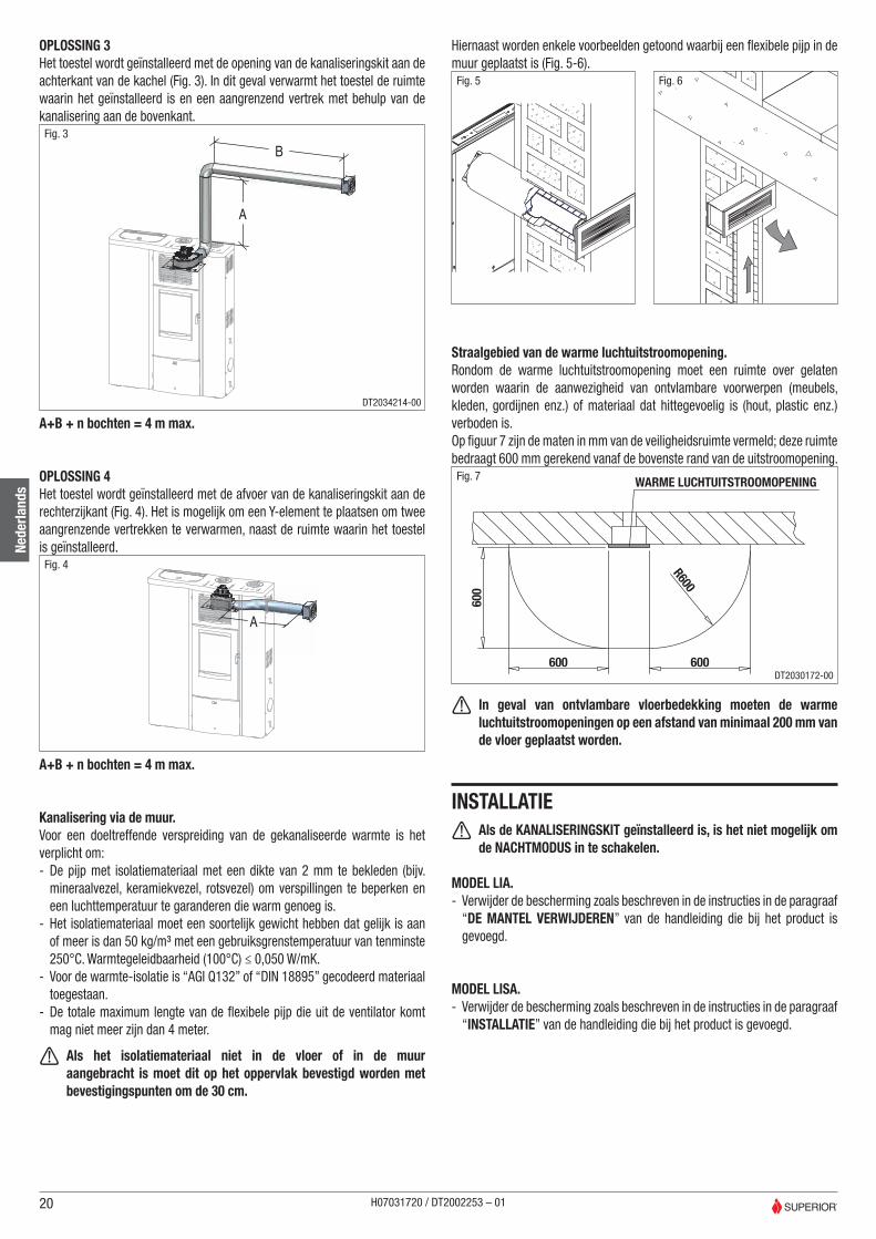
OPLOSSING 3Het toestel wordt geïnstalleerd met de opening van de kanaliseringskit aan de achterkant van de kachel (Fig. 3). In dit geval verwarmt het toestel de ruimte waarin het geïnstalleerd is en een aangrenzend vertrek met behulp van de kanalisering aan de bovenkant.
A
BFig. 3
DT2034214-00
A+B + n bochten = 4 m max.
OPLOSSING 4Het toestel wordt geïnstalleerd met de afvoer van de kanaliseringskit aan de rechterzijkant (Fig. 4). Het is mogelijk om een Y-element te plaatsen om twee aangrenzende vertrekken te verwarmen, naast de ruimte waarin het toestel is geïnstalleerd.
A
Fig. 4
A+B + n bochten = 4 m max.
Kanalisering via de muur.Voor een doeltreffende verspreiding van de gekanaliseerde warmte is het verplicht om: - De pijp met isolatiemateriaal met een dikte van 2 mm te bekleden (bijv. mineraalvezel, keramiekvezel, rotsvezel) om verspillingen te beperken en een luchttemperatuur te garanderen die warm genoeg is.
- Het isolatiemateriaal moet een soortelijk gewicht hebben dat gelijk is aan of meer is dan 50 kg/m³ met een gebruiksgrenstemperatuur van tenminste 250°C. Warmtegeleidbaarheid (100°C) ≤ 0,050 W/mK.
- Voor de warmte-isolatie is “AGI Q132” of “DIN 18895” gecodeerd materiaal toegestaan.
- De totale maximum lengte van de flexibele pijp die uit de ventilator komt mag niet meer zijn dan 4 meter.
a Als het isolatiemateriaal niet in de vloer of in de muur aangebracht is moet dit op het oppervlak bevestigd worden met bevestigingspunten om de 30 cm.
Hiernaast worden enkele voorbeelden getoond waarbij een flexibele pijp in de muur geplaatst is (Fig. 5-6).Fig. 5 Fig. 6
Straalgebied van de warme luchtuitstroomopening.Rondom de warme luchtuitstroomopening moet een ruimte over gelaten worden waarin de aanwezigheid van ontvlambare voorwerpen (meubels, kleden, gordijnen enz.) of materiaal dat hittegevoelig is (hout, plastic enz.) verboden is.Op figuur 7 zijn de maten in mm van de veiligheidsruimte vermeld; deze ruimte bedraagt 600 mm gerekend vanaf de bovenste rand van de uitstroomopening.
R600
600
600600
WARME LUCHTUITSTROOMOPENINGFig. 7
DT2030172-00
a In geval van ontvlambare vloerbedekking moeten de warme luchtuitstroomopeningen op een afstand van minimaal 200 mm van de vloer geplaatst worden.
INSTALLATIE a Als de KANALISERINGSKIT geïnstalleerd is, is het niet mogelijk om
de NACHTMODUS in te schakelen.
MODEL LIA. - Verwijder de bescherming zoals beschreven in de instructies in de paragraaf “DE MANTEL VERWIJDEREN” van de handleiding die bij het product is gevoegd.
MODEL LISA. - Verwijder de bescherming zoals beschreven in de instructies in de paragraaf “INSTALLATIE” van de handleiding die bij het product is gevoegd.
20
Nede
rland
s
H07031720 / DT2002253 – 01
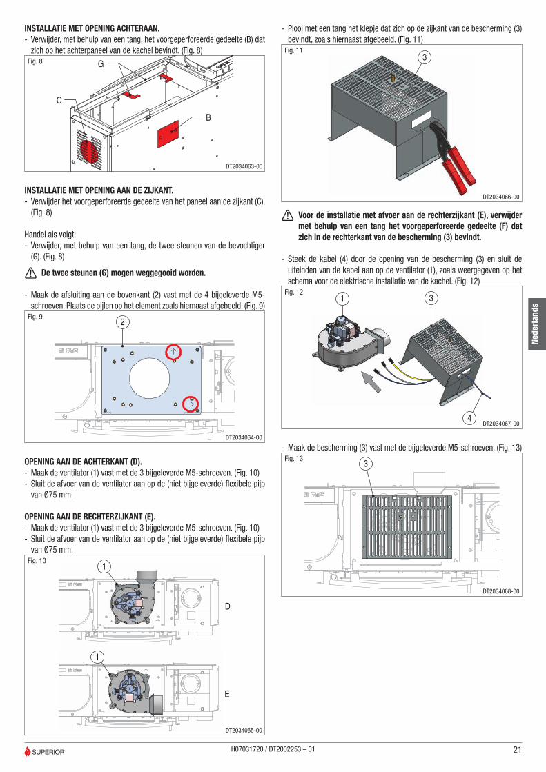
INSTALLATIE MET OPENING ACHTERAAN. - Verwijder, met behulp van een tang, het voorgeperforeerde gedeelte (B) dat zich op het achterpaneel van de kachel bevindt. (Fig. 8)
C
B
GFig. 8
DT2034063-00
INSTALLATIE MET OPENING AAN DE ZIJKANT. - Verwijder het voorgeperforeerde gedeelte van het paneel aan de zijkant (C). (Fig. 8)
Handel als volgt: - Verwijder, met behulp van een tang, de twee steunen van de bevochtiger (G). (Fig. 8)
a De twee steunen (G) mogen weggegooid worden.
- Maak de afsluiting aan de bovenkant (2) vast met de 4 bijgeleverde M5-schroeven. Plaats de pijlen op het element zoals hiernaast afgebeeld. (Fig. 9)
2Fig. 9
DT2034064-00
OPENING AAN DE ACHTERKANT (D). - Maak de ventilator (1) vast met de 3 bijgeleverde M5-schroeven. (Fig. 10) - Sluit de afvoer van de ventilator aan op de (niet bijgeleverde) flexibele pijp van Ø75 mm.
OPENING AAN DE RECHTERZIJKANT (E). - Maak de ventilator (1) vast met de 3 bijgeleverde M5-schroeven. (Fig. 10) - Sluit de afvoer van de ventilator aan op de (niet bijgeleverde) flexibele pijp van Ø75 mm.
D
E
1
1
Fig. 10
DT2034065-00
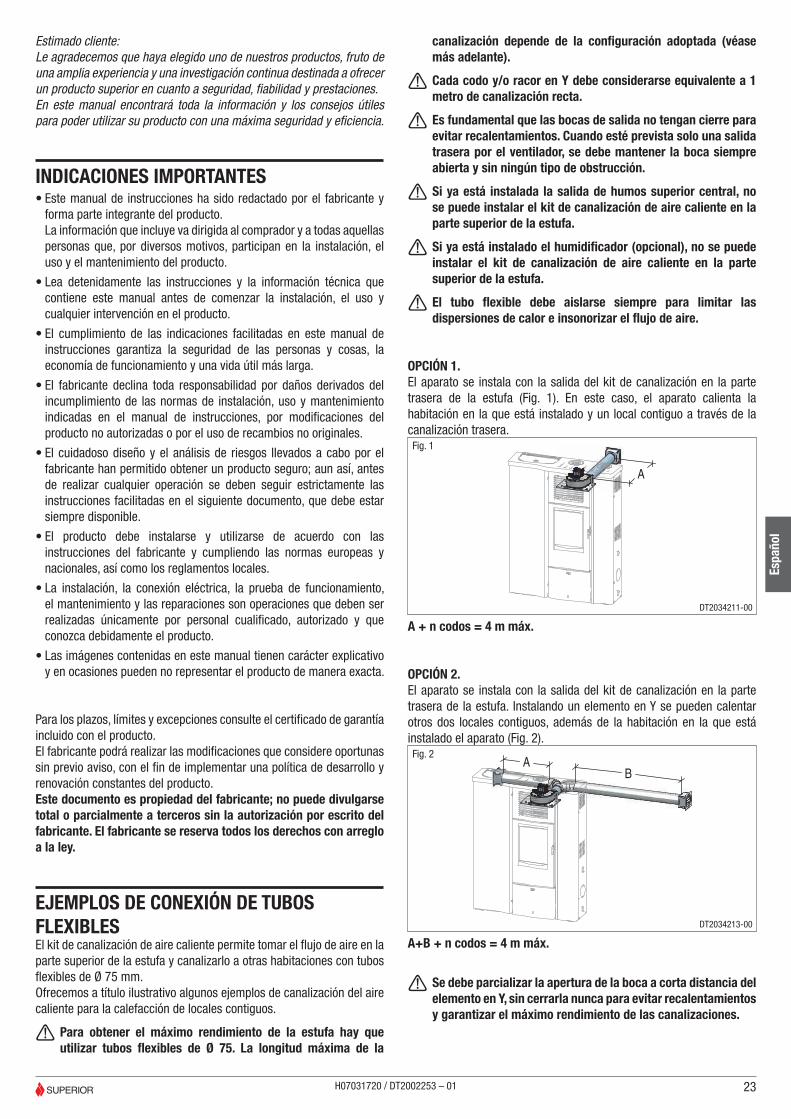
- Plooi met een tang het klepje dat zich op de zijkant van de bescherming (3) bevindt, zoals hiernaast afgebeeld. (Fig. 11)
3Fig. 11
DT2034066-00
a Voor de installatie met afvoer aan de rechterzijkant (E), verwijder met behulp van een tang het voorgeperforeerde gedeelte (F) dat zich in de rechterkant van de bescherming (3) bevindt.
- Steek de kabel (4) door de opening van de bescherming (3) en sluit de uiteinden van de kabel aan op de ventilator (1), zoals weergegeven op het schema voor de elektrische installatie van de kachel. (Fig. 12)
1 3
4
Fig. 12
DT2034067-00
- Maak de bescherming (3) vast met de bijgeleverde M5-schroeven. (Fig. 13)
3Fig. 13
DT2034068-00
21
Nede
rland
s
H07031720 / DT2002253 – 01

- Maak de kabel vast met het bijgeleverde klemmetje (7), zoals hiernaast afgebeeld. Plaats de haken met de koppeling (6) in de aangegeven punten en schuif de kabel erdoor. (Fig. 14-15)
7
Fig. 14
DT2033962-00
6
Fig. 15
DT2034069-00
a Controleer of de kabel niet in aanraking kan komen met onderdelen die warm kunnen worden.
- Maak de 2-pins klem vast aan het andere uiteinde van de kabel in de positie AUX 1 op de kaart, zoals hiernaast weergegeven (Fig. 16) en op het schema voor de elektrische installatie van de kachel.
AU
X 1Fig. 16
- Maak de aarddraad vast op de kaart zoals afgebeeld op het schema voor de elektrische installatie van de kachel.
- Maak de 2-pins klem (9) vast in de positie N.H20 op de kaart zoals afgebeeld, om de werking van de kachel te vermijden in de modaliteit “NACHT” (Fig.17).
N.H
2O
Fig. 17
- Monteer de gietijzeren plaat, het voorpaneel en de mantel opnieuw in omgekeerde volgorde.
- Verwijder de afsluiting aan de linkerzijkant (H) door de zelftappers te verwijderen. (Fig. 18)
H
Fig. 18
DT2034071-00
- Open het deksel van het reservoir en draai de pijp die de sonde ondersteunt (I) totdat de bovenkant van de schroeven zichtbaar is. Verwijder de eerste schroef (L) zoals afgebeeld. Let erop dat deze niet in het reservoir valt. (Fig. 19)
L
I
Fig. 19
DT2034072-00
- Steek de sonde in de pijp totdat ze in contact komt met de andere schroef. - Breng de afsluiting aan de zijkant weer aan. - Monteer de mantel opnieuw in omgekeerde volgorde.
- Maak op de bescherming (2) de schroef M5x35 (8) vast. Steek ze door het midden van de afdekking (N), zoals afgebeeld op figuur 20.
8
2
N
Fig. 20
DT2034133-00
22
Nede
rland
s
H07031720 / DT2002253 – 01
Estimado cliente:Le agradecemos que haya elegido uno de nuestros productos, fruto de una amplia experiencia y una investigación continua destinada a ofrecer un producto superior en cuanto a seguridad, fiabilidad y prestaciones.En este manual encontrará toda la información y los consejos útiles para poder utilizar su producto con una máxima seguridad y eficiencia.
INDICACIONES IMPORTANTES• Este manual de instrucciones ha sido redactado por el fabricante y
forma parte integrante del producto.La información que incluye va dirigida al comprador y a todas aquellas personas que, por diversos motivos, participan en la instalación, el uso y el mantenimiento del producto.
• Lea detenidamente las instrucciones y la información técnica que contiene este manual antes de comenzar la instalación, el uso y cualquier intervención en el producto.
• El cumplimiento de las indicaciones facilitadas en este manual de instrucciones garantiza la seguridad de las personas y cosas, la economía de funcionamiento y una vida útil más larga.
• El fabricante declina toda responsabilidad por daños derivados del incumplimiento de las normas de instalación, uso y mantenimiento indicadas en el manual de instrucciones, por modificaciones del producto no autorizadas o por el uso de recambios no originales.
• El cuidadoso diseño y el análisis de riesgos llevados a cabo por el fabricante han permitido obtener un producto seguro; aun así, antes de realizar cualquier operación se deben seguir estrictamente las instrucciones facilitadas en el siguiente documento, que debe estar siempre disponible.
• El producto debe instalarse y utilizarse de acuerdo con las instrucciones del fabricante y cumpliendo las normas europeas y nacionales, así como los reglamentos locales.
• La instalación, la conexión eléctrica, la prueba de funcionamiento, el mantenimiento y las reparaciones son operaciones que deben ser realizadas únicamente por personal cualificado, autorizado y que conozca debidamente el producto.
• Las imágenes contenidas en este manual tienen carácter explicativo y en ocasiones pueden no representar el producto de manera exacta.
Para los plazos, límites y excepciones consulte el certificado de garantía incluido con el producto.El fabricante podrá realizar las modificaciones que considere oportunas sin previo aviso, con el fin de implementar una política de desarrollo y renovación constantes del producto.Este documento es propiedad del fabricante; no puede divulgarse total o parcialmente a terceros sin la autorización por escrito del fabricante. El fabricante se reserva todos los derechos con arreglo a la ley.
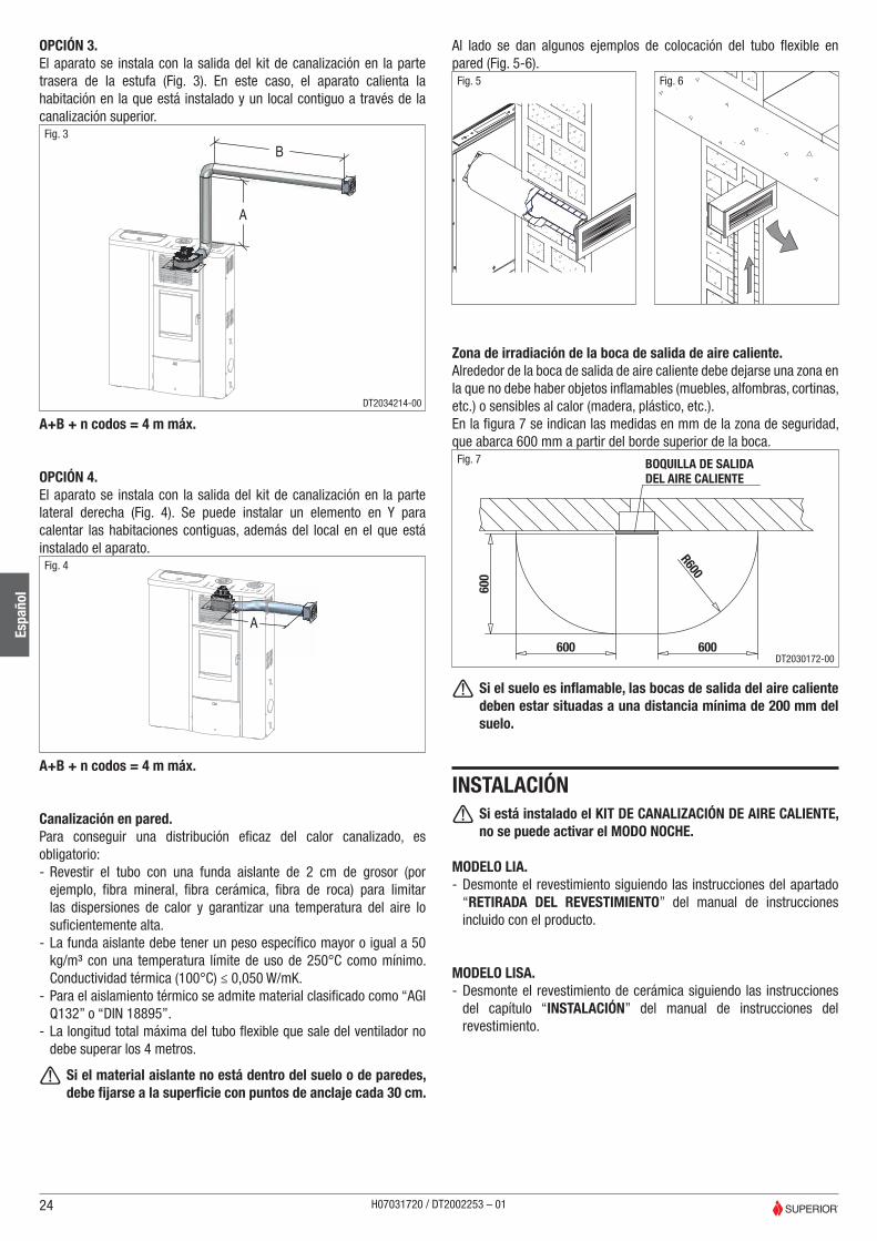
EJEMPLOS DE CONEXIÓN DE TUBOS FLEXIBLESEl kit de canalización de aire caliente permite tomar el flujo de aire en la parte superior de la estufa y canalizarlo a otras habitaciones con tubos flexibles de Ø 75 mm.Ofrecemos a título ilustrativo algunos ejemplos de canalización del aire caliente para la calefacción de locales contiguos.
a Para obtener el máximo rendimiento de la estufa hay que utilizar tubos flexibles de Ø 75. La longitud máxima de la
canalización depende de la configuración adoptada (véase más adelante).
a Cada codo y/o racor en Y debe considerarse equivalente a 1 metro de canalización recta.
a Es fundamental que las bocas de salida no tengan cierre para evitar recalentamientos. Cuando esté prevista solo una salida trasera por el ventilador, se debe mantener la boca siempre abierta y sin ningún tipo de obstrucción.
a Si ya está instalada la salida de humos superior central, no se puede instalar el kit de canalización de aire caliente en la parte superior de la estufa.
a Si ya está instalado el humidificador (opcional), no se puede instalar el kit de canalización de aire caliente en la parte superior de la estufa.
a El tubo flexible debe aislarse siempre para limitar las dispersiones de calor e insonorizar el flujo de aire.
OPCIÓN 1.El aparato se instala con la salida del kit de canalización en la parte trasera de la estufa (Fig. 1). En este caso, el aparato calienta la habitación en la que está instalado y un local contiguo a través de la canalización trasera.
A
Fig. 1
DT2034211-00
A + n codos = 4 m máx.
OPCIÓN 2.El aparato se instala con la salida del kit de canalización en la parte trasera de la estufa. Instalando un elemento en Y se pueden calentar otros dos locales contiguos, además de la habitación en la que está instalado el aparato (Fig. 2).
AB
Fig. 2
DT2034213-00
A+B + n codos = 4 m máx.
a Se debe parcializar la apertura de la boca a corta distancia del elemento en Y, sin cerrarla nunca para evitar recalentamientos y garantizar el máximo rendimiento de las canalizaciones.
23
Espa
ñol
H07031720 / DT2002253 – 01
OPCIÓN 3.El aparato se instala con la salida del kit de canalización en la parte trasera de la estufa (Fig. 3). En este caso, el aparato calienta la habitación en la que está instalado y un local contiguo a través de la canalización superior.
A
BFig. 3
DT2034214-00
A+B + n codos = 4 m máx.
OPCIÓN 4.El aparato se instala con la salida del kit de canalización en la parte lateral derecha (Fig. 4). Se puede instalar un elemento en Y para calentar las habitaciones contiguas, además del local en el que está instalado el aparato.
A
Fig. 4
A+B + n codos = 4 m máx.
Canalización en pared.Para conseguir una distribución eficaz del calor canalizado, es obligatorio: - Revestir el tubo con una funda aislante de 2 cm de grosor (por ejemplo, fibra mineral, fibra cerámica, fibra de roca) para limitar las dispersiones de calor y garantizar una temperatura del aire lo suficientemente alta.
- La funda aislante debe tener un peso específico mayor o igual a 50 kg/m³ con una temperatura límite de uso de 250°C como mínimo. Conductividad térmica (100°C) ≤ 0,050 W/mK.
- Para el aislamiento térmico se admite material clasificado como “AGI Q132” o “DIN 18895”.
- La longitud total máxima del tubo flexible que sale del ventilador no debe superar los 4 metros.
a Si el material aislante no está dentro del suelo o de paredes, debe fijarse a la superficie con puntos de anclaje cada 30 cm.
Al lado se dan algunos ejemplos de colocación del tubo flexible en pared (Fig. 5-6).Fig. 5 Fig. 6
Zona de irradiación de la boca de salida de aire caliente.Alrededor de la boca de salida de aire caliente debe dejarse una zona en la que no debe haber objetos inflamables (muebles, alfombras, cortinas, etc.) o sensibles al calor (madera, plástico, etc.).En la figura 7 se indican las medidas en mm de la zona de seguridad, que abarca 600 mm a partir del borde superior de la boca.
R600
600
600600
BOQUILLA DE SALIDADEL AIRE CALIENTE
Fig. 7
DT2030172-00
a Si el suelo es inflamable, las bocas de salida del aire caliente deben estar situadas a una distancia mínima de 200 mm del suelo.
INSTALACIÓN a Si está instalado el KIT DE CANALIZACIÓN DE AIRE CALIENTE, no se puede activar el MODO NOCHE.
MODELO LIA. - Desmonte el revestimiento siguiendo las instrucciones del apartado “RETIRADA DEL REVESTIMIENTO” del manual de instrucciones incluido con el producto.
MODELO LISA. - Desmonte el revestimiento de cerámica siguiendo las instrucciones del capítulo “INSTALACIÓN” del manual de instrucciones del revestimiento.
24
Espa
ñol
H07031720 / DT2002253 – 01

INSTALACIÓN CON SALIDA TRASERA. - Quite la parte precortada (B) situada en la parte trasera de la estufa utilizando un alicate. (Fig. 8)
C
B
GFig. 8
DT2034063-00
INSTALACIÓN CON SALIDA LATERAL. - Quite la parte precortada del panel lateral (C). (Fig. 8)
Siga estos pasos: - Desmonte los dos soportes del humidificador (G) utilizando un alicate. (Fig. 8)
a Los dos soportes (G) son desechables.
- Fije el cierre superior (2) con 4 de los tornillos M5 incluidos. Las flechas marcadas en la pieza deben quedar orientadas de la manera indicada al lado (Fig. 9)
2Fig. 9
DT2034064-00
SALIDA TRASERA (D). - Fije el ventilador (1) con 3 de los tornillos M5 incluidos. (Fig. 10) - Conecte la salida del ventilador con el tubo flexible Ø 75 mm no incluido.
SALIDA LATERAL DERECHA (E). - Fije el ventilador (1) con 3 de los tornillos M5 incluidos. (Fig. 10) - Conecte la salida del ventilador con el tubo flexible Ø 75 mm no incluido.
D
E
1
1
Fig. 10
DT2034065-00
- Doble con un alicate la lengüeta lateral de la protección (3) tal y como se indica al lado. (Fig. 11)
3Fig. 11
DT2034066-00
a Para la instalación con salida lateral derecha (E) quite la parte precortada (F) que se encuentra en la parte derecha de la protección (3) utilizando un alicate.
- Pase el cable cableado (4) por la ranura de la protección (3) y conecte los terminales del cable cableado al ventilador (1) tal y como se indica en el esquema eléctrico de la estufa. (Fig. 12)
1 3
4
Fig. 12
DT2034067-00
- Fije la protección (3) con los tornillos M5 incluidos. (Fig. 13)
3Fig. 13
DT2034068-00
25
Espa
ñol
H07031720 / DT2002253 – 01

- Sujete el cable con la abrazadera (7) incluida, de la manera que se indica al lado. Coloque los lazos con enganche (6) en los puntos indicados y pase el cable cableado. (Fig. 14-15)
7
Fig. 14
DT2033962-00
6
Fig. 15
DT2034069-00
a Compruebe que el cable cableado no entre en contacto con partes que puedan calentarse.
- Acople el borne de 2 PINS al otro extremo del cable cableado en la posición AUX 1 de la tarjeta, tal y como se indica al lado (Fig. 16) y en el esquema eléctrico de la estufa.
AU
X 1Fig. 16
- Fije el cable de puesta a tierra a la tarjeta de la manera indicada en el esquema eléctrico de la estufa.
- Acople el borne de 2 PINS (9) en la posición N.H2O de la tarjeta, tal y como se indica, para deshabilitar el funcionamiento de la estufa en modo “NOCHE” (Fig. 17).
N.H
2O
Fig. 17
- Vuelva a montar la placa de hierro fundido, el frontal y el revestimiento siguiendo los pasos de desmontaje en orden inverso.
- Quite el cierre lateral izquierdo (H) extrayendo los tornillos autorroscantes que lo sujetan. (Fig. 18)
H
Fig. 18
DT2034071-00
- Abra la tapa del depósito y gire el tubo de soporte de la sonda (I) hasta que se vean las cabezas de los tornillos. Quite el primer tornillo (L) de la manera indicada en la figura, con cuidado para que no caiga dentro del depósito. (Fig. 19)
L
I
Fig. 19
DT2034072-00
- Empuje la sonda hacia el interior del tubo hasta que toque el otro tornillo.
- Vuelva a montar el cierre lateral. - Vuelva a montar el revestimiento siguiendo los pasos de desmontaje en orden inverso.
- Fije en la protección (2) el tornillo M5x35 (8) haciéndolo pasar por el centro del embellecedor (N) de la manera indicada en la figura 20.
8
2
N
Fig. 20
DT2034133-00
26
Espa
ñol
H07031720 / DT2002253 – 01

Prezado Cliente,Agradecemos por ter escolhido um dos nossos produtos, fruto de uma longa experiência e de uma contínua investigação para obter um produto superior em termos de segurança, fiabilidade e desempenho.Neste manual encontrará todas as informações e conselhos úteis para poder utilizar o seu produto com a máxima segurança e eficiência.
INFORMAÇÕES IMPORTANTES• Este manual de instruções foi redigido pelo fabricante e faz parte
integrante do produto.As informações referidas no mesmo são endereçadas ao comprador e a todas aquelas pessoas que a vário título participam na instalação, no uso e na manutenção do produto.
• Leia com atenção as instruções e as informações técnicas constantes neste manual, antes de efetuar a instalação, utilização ou qualquer intervenção no produto.
• O cumprimento das indicações constantes neste manual garante a segurança de pessoas e bens; assegura um funcionamento económico e uma maior durabilidade.
• O fabricante não pode ser considerado responsável por danos derivados da inobservância das normas de instalação, utilização e manutenção constantes no manual de instruções, por modificações do produto não autorizadas ou pela utilização de peças não originais.
• O atento concebimento e a análise dos riscos feitos pelo fabricante permitiram a realização de um produto seguro; todavia antes de efetuar qualquer operação, se recomenda de respeitar escrupulosamente as instruções apresentadas no seguinte documento, e de o ter sempre à disposição.
• A instalação e utilização do aparelho devem ser feitas de acordo com as instruções do fabricante, respeitando as disposições legislativas europeias, nacionais e regulamentos locais.
• A instalação, a ligação elétrica, o controlo do funcionamento, a manutenção e as reparações são operações que devem ser realizadas apenas por pessoal qualificado, autorizado e que possua o conhecimento necessário do produto.
• As figuras deste manual são a título explicativo e podem não representar com exatidão o produto.
Para os termos, limites e exclusões consulte o certificado de garantia anexado ao produto.Com o objetivo de aplicar uma política de constante desenvolvimento e renovação do produto, o fabricante pode fazer as modificações que considerar oportunas sem aviso prévio.Este manual é de propriedade do fabricante, não pode ser divulgado total ou parcialmente a terceiros sem autorização escrita do mesmo. O fabricante reserva-se todos os direitos ao abrigo da lei.
EXEMPLOS DE LIGAÇÃO COM TUBOS FLEXÍVEISO conjunto de canalização para o ar quente permite extrair o fluxo do ar na parte superior da salamandra e canalizá-lo noutros ambientes com tubos flexíveis Ø 75 mm.Fornecemos alguns exemplos a título demonstrativo de canalização do ar quente para o aquecimento de locais adjacentes.
a O ótimo rendimento da salamandra obtém-se com tubos flexíveis Ø 75. O comprimento máximo da canalização depende da configuração adotada (veja a seguir).
a Cada curva e/ou união a Y deve ser considerada igual a 1 metro de canalização direita.
a É fundamental que as grelhas de saída sejam sem fecho para evitar sobreaquecimentos. Nos casos em que estiver presente uma única saída traseira do ventilador, é necessário manter a mesma saída sempre aberta e sem nenhum tipo de obstrução.
a Não é possível instalar o conjunto de canalização do ar quente na parte superior da salamandra se já estiver instalada a chaminé superior central.
a Não é possível instalar o conjunto de canalização do ar quente na parte superior da salamandra se já estiver instalado o humidificador (opcional).
a O tubo flexível deve estar sempre isolado para limitar dispersões de calor e insonorizar o fluxo do ar.
SOLUÇÃO 1.O aparelho instala-se com a saída do conjunto de canalização na parte posterior da salamandra (Fig. 1). Neste caso o aparelho aquece o local onde estiver instalado e um local adjacente através da canalização traseira.
A
Fig. 1
DT2034211-00
A + n curvas = 4 m máx
SOLUÇÃO 2.O aparelho instala-se com a saída do conjunto de canalização na parte traseira da salamandra. Através da instalação de um elemento a Y é possível aquecer outros dois locais adjacentes, para além do ambiente no qual estiver instalado o aparelho (Fig. 2).
AB
Fig. 2
DT2034213-00
A+B + n curve = 4 m máx
a É necessário parcializar a abertura de saída a breve distância do elemento a Y sem nunca a fechar para evitar sobreaquecimentos e para um ótimo rendimento das canalizações.
27
Port
uguê
s
H07031720 / DT2002253 – 01

SOLUÇÃO 3.O aparelho instala-se com a saída do conjunto de canalização na parte posterior da salamandra (Fig. 3). Neste caso o aparelho aquece o ambiente no qual estiver instalado e um local adjacente através da canalização superior.
A
BFig. 3
DT2034214-00
A+B + n curvas = 4 m máx.
SOLUÇÃO 4.O aparelho instala-se com a saída do conjunto de canalização na parte lateral direita (Fig. 4). É possível instalar um elemento a Y para aquecer dois ambientes adjacentes, para além do ambiente no qual o aparelho estiver instalado.
A
Fig. 4
A+B + n curvas = 4 m máx.
Canalização na parede.Para uma distribuição eficaz do calor canalizado é obrigatório: - Revestir o tubo com manga isolante com 2 cm de espessura (ex. fibra mineral, fibra cerâmica, fibra de rocha) de modo a limitar as dispersões e para garantir uma temperatura do ar suficientemente alta;
- A manga isolante deve ter peso específico igual ou superior a 50 kg/m³ com uma temperatura limite de utilização de pelo menos 250°C. Condutividade térmica (100°C) ≤ 0,050 W/mK.
- Para o isolamento térmico é permitido material codificado “AGI Q132” ou “DIN 18895”;
- O comprimento total máximo do tubo flexível que sai do ventilador não deve superar 4 metros.
a Se o material isolante não estiver dentro do piso ou de paredes é necessário fixá-lo à superfície com pontos de fixação a cada 30 cm.
Ao lado alguns exemplos de disposição do tubo flexível na parede (Fig. 5-6).Fig. 5 Fig. 6
Zona de radiação da saída de ar quente.À volta da saída de ar quente é necessário manter uma zona dentro da qual é proibida a presença de objetos inflamáveis (móveis, tapetes, cortinas, etc.) ou sensíveis ao calor (madeira, plástico, etc.).Na figura 7 estão indicadas as medidas em mm da zona de segurança, tal zona inclui os 600 mm considerados partindo da borda superior da saída.
R600
600
600600
SAÍDA DE AR QUENTEFig. 7
DT2030172-00
a Se presente um piso inflamável, as saídas de ar quente têm de ser instaladas a uma distância de pelo menos 200 mm do chão.
1.0 INSTALAÇÃO a Se o CONJUNTO DE CANALIZAÇÃO AR QUENTE estiver instalado, não é possível activar a FUNÇÃO NOCTURNA.
MODELO LIA. - Tire o revestimento seguindo as instruções referidas no parágrafo “REMOÇÃO REVESTIMENTO” do manual de instruções anexado ao produto.
MODELO LISA. - Remova o revestimento em cerâmica seguindo as instruções indicadas no capítulo “INSTALAÇÃO” do manual de instruções do revestimento.
28
Port
uguê
s
H07031720 / DT2002253 – 01

INSTALAÇÃO COM SAÍDA TRASEIRA. - Com o auxílio de uma pinça tire o semi-corte (B) colocado no painel traseiro da salamandra. (Fig. 8)
C
B
GFig. 8
DT2034063-00
INSTALAÇÃO COM SAÍDA LATERAL. - Tire o semi-corte no painel lateral (C). (Fig. 8)
Proceda como a seguir: - Com o auxílio de uma pinça tire os dois suportes do humidificador (G). (Fig. 8)
a Os dois suportes (G) são irrecuperáveis.
- Fixe o fecho superior (2) com 4 parafusos M5 em dotação. Posicione as setas presentes na peça como representado ao lado. (Fig. 9)
2Fig. 9
DT2034064-00
SAÍDA TRASEIRA (D). - Fixe o ventilador (1) com 3 parafusos M5 em dotação. (Fig. 10) - Ligue a saída do ventilador com o tubo flexível Ø 75 mm não fornecido em dotação.
SAÍDA LATERAL DIREITA (E). - Fixe o ventilador (1) com 3 parafusos M5 em dotação. (Fig. 10) - Ligue a saída do ventilador com o tubo flexível Ø 75 mm não fornecido em dotação.
D
E
1
1
Fig. 10
DT2034065-00
- Dobre com uma pinça a lingueta lateral presente na proteção (3) como indicado ao lado. (Fig. 11)
3Fig. 11
DT2034066-00
a Para a instalação com saída lateral direita (E) tire, com o auxílio de uma pinça, o semi-corte (F) que se encontra na parte direita da proteção (3).
- Faça passar o cabo cablado (4) através da abertura na proteção (3) e ligue os terminais do cabo cablado no ventilador (1) como indicado no esquema elétrico da salamandra. (Fig. 12)
1 3
4
Fig. 12
DT2034067-00
- Fixe a proteção (3) com os parafusos M5 em dotação. (Fig. 13)
3Fig. 13
DT2034068-00
29
Port
uguê
s
H07031720 / DT2002253 – 01

- Fixe o cabo com a abraçadeira (7) em dotação como indicado ao lado. Posicione os cordões com engate (6) nos pontos indicados e faça passar o cabo cablado. (Fig. 14-15).
7
Fig. 14
DT2033962-00
6
Fig. 15
DT2034069-00
a Verifique que o cabo cablado não entre em contacto com as partes que se podem esquentar.
- Ligue o terminal de 2 PINOS na outra extremidade do cabo cablado na posição AUX 1 na placa, como indicado ao lado (Fig. 16) e no esquema elétrico da salamandra.
AU
X 1Fig. 16
- Fixe o cabo de ligação à terra na placa, como indicado no esquema elétrico da salamandra.
- Ligue o terminal de 2 PINOS (9) na posição N.H2O na placa, como indicado, a fim de inibir o funcionamento da salamandra no modo “NOITE” (Fig. 17).
N.H
2O
Fig. 17
- Volte a montar o plano em ferro fundido, o painel frontal e o revestimento pela ordem inversa à de desmontagem.
- Tire o fecho lateral esquerdo (H) removendo os parafusos autorroscantes que a fixam. (Fig. 18)
H
Fig. 18
DT2034071-00
- Abra a tampa do depósito e rode o tubo suporte sonda (I) até se verem as cabeças dos parafusos. Tire o primeiro parafuso (L) como indicado na figura, prestando atenção que não caia dentro do depósito. (Fig. 19)
L
I
Fig. 19
DT2034072-00
- Empurre a sonda para dentro do tubo de maneira que não toque o outro parafuso.
- Volte a montar o fecho lateral. - Volte a montar o revestimento na ordem inversa a quanto executado para a desmontagem.
- Fixe sobre a proteção (2) o parafuso M5x35 (8) fazendo-a passar pelo centro do cobre-furo (N) como indicado na figura 20.
8
2
N
Fig. 20
DT2034133-00
30
Port
uguê
s
H07031720 / DT2002253 – 01
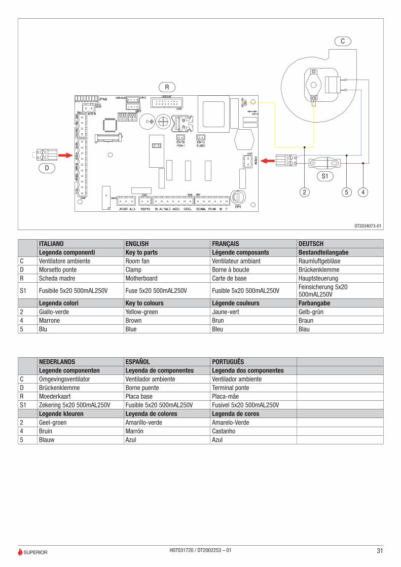
NEDERLANDS ESPAÑOL PORTUGUÊSLegende componenten Leyenda de componentes Legenda dos componentes
C Omgevingsventilator Ventilador ambiente Ventilador ambienteD Brückenklemme Borne puente Terminal ponteR Moederkaart Placa base Placa-mãeS1 Zekering 5x20 500mAL250V Fusible 5x20 500mAL250V Fusível 5x20 500mAL250V
Legende kleuren Leyenda de colores Legenda de cores2 Geel-groen Amarillo-verde Amarelo-Verde4 Bruin Marrón Castanho5 Blauw Azul Azul
DS1
C
R
2 5 4
ITALIANO ENGLISH FRANÇAIS DEUTSCHLegenda componenti Key to parts Légende composants Bestandteilangabe
C Ventilatore ambiente Room fan Ventilateur ambiant RaumluftgebläseD Morsetto ponte Clamp Borne à boucle BrückenklemmeR Scheda madre Motherboard Carte de base Hauptsteuerung
S1 Fusibile 5x20 500mAL250V Fuse 5x20 500mAL250V Fusible 5x20 500mAL250V Feinsicherung 5x20 500mAL250V
Legenda colori Key to colours Légende couleurs Farbangabe2 Giallo-verde Yellow-green Jaune-vert Gelb-grün4 Marrone Brown Brun Braun5 Blu Blue Bleu Blau
31
DT2034073-01
H07031720 / DT2002253 – 01
Via Montello, 2231011 Casella d’Asolo (TV) - ITALY
Tel. +39.04235271 - Fax +39.042355178www.superiorstufe.com
e-mail:[email protected]
H070
3172
0 / D
T200
2253
- R
ev. 0
1 -
(11/
2013
)