
Alta 2005 Sx Fires
32
1 ALTA 2005 - SX FIRE SUMMIT ENGINEERING DESIGN FOR LOWERING FIRE RISK Graeme Miller Miller Metallurgical Services [email protected] INDEX 1 SUMMARY 2 2 INTRODUCTION 3 3 SX FIRE EXPERIENCES 4 4 THE FIRE PROCESS 7 5 INITIATION FACTORS 13 6 CONTROL OF STATIC ELECTRICITY 16 7 FUEL CONTROL FACTORS 20 8 FIRE PLUME AND RADIANT HEAT ISSUES 22 9 EXTINGUISHMENT 24 10 ESCALATION SCENARIOS ANALYSIS 25 11 MINIMISING BUSINESS INTERRUPTION 27 12 CONCLUSIONS 29 13 REFERENCES 30 14 APPENDIX 31
Transcript of Alta 2005 Sx Fires

1
ALTA 2005 - SX FIRE SUMMIT
ENGINEERING DESIGN FOR LOWERING FIRE RISK
Graeme Miller
Miller Metallurgical Services
INDEX
1 SUMMARY
2
2 INTRODUCTION
3
3 SX FIRE EXPERIENCES
4
4 THE FIRE PROCESS
7
5 INITIATION FACTORS
13
6 CONTROL OF STATIC ELECTRICITY
16
7 FUEL CONTROL FACTORS
20
8 FIRE PLUME AND RADIANT HEAT ISSUES
22
9 EXTINGUISHMENT
24
10 ESCALATION SCENARIOS ANALYSIS
25
11 MINIMISING BUSINESS INTERRUPTION
27
12 CONCLUSIONS
29
13 REFERENCES 30
14 APPENDIX 31

2
1 SUMMARY
The fire risk profile for solvent extraction plants (SX) has been raised recently due to two fire events at the Olympic Dam Operation (ODO) in South Australia and two other recent large fire events. Investigation of the first of the ODO events in 1999 did not result in any public domain information being made available. However the second event in 2001 has been made public via an edited internal report of the South Australian Metropolitan Fire Service
Many new and existing SX plants recognise that a fire risk identification and reduction activity needs to be undertaken to allow proper risk assessment of the alternate approaches available. This paper provides some historical perspective on SX fires; as well as interpretation of the SAMFS report as it relates to design aspects of SX plants.
The main SX fires have highlighted a number of failures of engineering and procedural controls. All these are well known in the hydrocarbon industries and need to be better appreciated in the mineral processing industries.
Fire prevention should be a paramount focus of SX plant design. This needs to include all the aspects of fuel supply, generation of flammable atmospheres, minimisation of static electricity and elimination of other ignition sources.
Many engineering companies have failed to ensure that all the available tools, standards and knowledge have been utilised in the design process. Some plants have been built without reference to even the most basic standards that should be in the toolkit of all designers.
Fire plume analysis and escalation scenario development are key tools in the understanding and minimisation of fire risk for SX plants. Both can provide significant benefits in eliminating risks (such as uncontrolled running pool fires) and involvement of other assets in a fire.
Business interruption planning needs to be made an integral part of the engineering control process. This ensures that the physical plant can be used after a fire event to maximise production and minimise the loss of cash flow.
Engineering controls are not enough for fire risk management. A strict system of risk management procedures and work descriptions needs to be in place and their use enforced and built into the site culture.
A significant number of SX plant fires can be traced to one or more failures of the operational management controls. Mostly this is related to a culture that is not focused on risk identification and removal but rather adherence to set protocols that become burdensome and observed more in the breach.
3
2 INTRODUCTION
The fire risk profile for solvent extraction plants (SX) has been raised recently due to two fire events at the Olympic Dam Operation (ODO) in South Australia and two other recent large fire events. Investigation of the first of the ODO events in 1999 did not result in any public domain information being made available. However the second event in 2001 has been made public via an edited internal report of the South Australian Metropolitan Fire Service (SAMFS) [1].
Many new and existing SX plants recognise that a fire risk identification and reduction activity needs to be undertaken to allow proper risk assessment of the alternate approaches available. This paper provides some historical perspective on SX fires; as well as interpretation of the SAMFS report as it relates to design aspects of SX plants. Further information on large hydrocarbon fires has been extracted from the literature along with significant input from the fire sciences. Particular attention is given to the aspects of:
Minimisation of fire occurrences
Minimisation of fire propagation
Assessment of fire fighting effectiveness
Recommendations for overall approach to the fire risk as well as detailed engineering aspects of implementation to ensure that the approach is properly implemented.
The author has been involved with the remediation of the ODO SX facility after the second fire event. No information that he has obtained under confidentiality with Western Mining has been divulged in this paper. Reliance is made only on the public domain information for the fire and on specific knowledge of general solvent extraction plant design and operation.
Much of the information in this paper is available in standard texts on the subjects of:
Fires,
Hydrocarbon storage and handling,
Fire initiation risk minimisation,
Fire escalation
Fire fighting, and
Management of hazardous areas.
All of the recommendations made are consistent with ‘good engineering practice’; particularly with regard to elimination of static electricity and protection of other assets in a fire event scenario.

4
3 SX FIRE EXPERIENCES
Introduction The experiences with SX fires have been sporadic over the last thirty to forty years. However in the recent past a number of large fires have occurred, that has focused the industry on fire safety and fire prevention. This section will quickly cover some of the more significant fires. Due to the limited space the treatment will be high level with the key points brought out. A more detailed analysis has been prepared for presentation to groups undertaking risk assessments of SX facilities (Miller [2]). Only the more significant fires involving large proportions of the SX organic have been addressed here. Other smaller fires have been reported that have involved only limited volumes of organic (Bateman [3]). In many cases there has been a knee-jerk reaction; to implement almost anything that could be construed as appearing to the decrease the risk of an SX fire. Many of the decisions have been made on the basis of limited technical knowledge. There is however a great deal of information that can be gained from the integrated knowledge base that exists outside of the mining and minerals processing industries. Kristainsand (1970’s) Not a lot of information is available regarding this event other than that it used a tertiary ammine extractant in a diluent similar to Rossing (McKenzie [4]). The fire was in the cobalt refinery and was reported to have been initiated from welding operations taking place during maintenance. Rossing (early 1980’s) The Rossing fire is the first that has been widely reported and has some significant anecdotal evidence still available (McKenzie [5], Sylvester [6], Kessler [7]). The plant used a tertiary ammine in a high flash point diluent to reconcentrate uranium after a primary ion exchange (IX) extraction. The plant had two trains of SX separated by a common tank farm, spillage handling and services area. The SX was supported off the ground by columns and beams as was the case with most SX plants built during that period. The fire started in a spillage sump in the central area and initiated the automatic fire sprinkler system. Being a hydrocarbon fire the sprinklers did not extinguish the fire. The sump filled with fire-water and the fire spread on the surface of the water until it was under the SX mixer-settlers. The vessels eventually failed from the fire underneath and contributed to the fuel load and the spread of the fire. The initiation of the fire is subject to some differences in recollection. However the consensus is that a leaking temporary hose delivered organic on to the drive of a sump pump, which subsequently ignited. The exact initiation scenario has not been recollected. Eventually one entire train of the SX was consumed by the fire incident. Production interruption was minimised since a second SX train was available. This decision to split the trains into two was a conscious one by the client and engineering company at the time (Bert Viljoen and Western Knapp). Gulf Chemicals (1980’s)

5
There is little independent evidence for this fire other than some anecdotal recollections (at least one remove from the operation (Goodman [8])). It appears that the general industry approach of referring to diluent as kerosene was taken one step further when kerosene was actually purchased for use in the plant. The plant was not designed or operated to cope with such a low flash point carrier; and a fire ensued that destroyed the SX facility. Olympic Dam 1999 No cause for this fire was published outside of Western Mining Corp. However some idea of the extent of the damage can be gauged from the SAMFS report [1] on the second fire. The fire involved the tank farm of the copper SX plant. The diluent was the industry standard with a high flash point. The fire began somewhere near the loaded organic tank and involved this tank and other nearby tanks storing organic. Fire fighting apparently managed to limit the damage to the loaded organic tank and local environs. There was no damage to the uranium circuit, nor to the copper mixer-settlers. Olympic Dam 2001 The 2001 Olympic Dam fire has been subject to significant reporting that has been made available through the SAMFS [1]. Not only has the level of damage been well documented but a likely ignition scenario proposed and tested. From this outcome it can be inferred that the ignition of the first fire is likely to be the same (or very similar) as the second fire. The fire started in the copper SX tankfarm and was of very significant size by the time that fire fighting appliances were able to reach the site. A significant quantity of water and foam was used in the extinguishment attempts that followed. The fire burnt for at least 36 hours in total; suffering many flare ups and re-escalation during this period. With the accumulation of fire-water in the below-ground tank farm, the fire spread to the uranium SX when the intermediate bund overflowed. This prolonged the fire and increased the number of assets involved. The fire was eventually extinguished when the fuel was consumed. Other near-by assets were preserved by the use of enclosure and cooling sprays. The copper SX mixer-settlers used a combination of metal sheeting and cooling sprays to prevent their involvement. Similar cooling sprays prevented the involvement of the large FRP pulsed columns at the edge of the fire area. Metcalf 2003 There has been very little public domain information made available on this incident by the owner. It is hoped that this situation will improve in the near future. Mariquita 2003 The Mariquita fire was witnessed from off the site. Further anecdotal information has been circulated in the industry that suggests the fire was started by welding or grinding activities near the SX vessels. The subsequent fire consumed the whole SX plant. No fire fighting activities were undertaken. No other assets were involved and there was no escalation of the fire outside of the SX area. The fire burnt all the available fuel and reduced the HDPE lined vessels to the aqueous water line.

6
The physical separation of the SX plant from the other assets was the prime reason for the lack of involvement of the other assets. The lack of any fire fighting did not introduce any excess fluids into the SX bunded area. As a result there were no running pool fires and the fire was contained within the SX bund. Asset separation and prevention of running pool fires were the prime factors behind the lack of escalation to other assets. Confidential Pilot Plant 2004 An SX pilot plant suffered a fire in an organic storage tank [9]. The fire appears to have started with the direct electric heating element in the tank. Escalation was prevented by the ability of the plant operators to extinguish the fire with local fire extinguishers. Lessons from the SX fires. It is evident that there are a number of common threads running through the initiation, escalation, and extinguishment activities that need to be considered when assessing the fire risk reduction protocols. In all cases there was some form of breakdown in procedural controls. These are not only the operational procedures but include a wide range of control failures: Site procedures for control of fuel escape
Site procedures for elimination of ignition
Site procurement procedures
Corporate procedures for risk reduction (escalation scenario development etc)
Engineering procedures for risk reduction (inclusion of expertise in hydrocarbon handling)
Detailed engineering procedures for compliance with Codes and Standards
It is not just the site operating procedures that need to be audited but also all the procedures used in the project development, implementation, operation and modification of the project. In all cases appropriate review of the procedures available and the actual practices adopted should have identified the increased risk profiles.
Another common thread is the realisation of the poor outcomes from positive fire fighting activities. Many of the fires were actively spread by the attempt to extinguish them. This is one of the corporate procedural failures in not considering the effects of actions in fire events. Scenario analysis is now a key aspect of more recent risk assessment tools. A key observation from all the fires is the speed with which they spread. The development from a small fire (that could be approached with a hand held extinguisher) to a very large fire was very rapid. A number of anecdotal reports indicate that many SX plants have small fires that are extinguished with appropriate hand held units. These do not normally involve the organic but the other combustibles in such plants – electrical cables, greases and oil accumulations, waste and trash accumulations.
7
4 THE FIRE PROCESS
The fire process itself is an interesting area of very intense and extensive study by a large number of organisations. When one delves into the process a little deeper it is easy to see that the fire process can be modelled theoretically for only small constrained volumes. Outside of this the fire tends to a combination of so many site and material specific factors that modelling usefulness is limited.
However the fire can be considered on a larger scale where (like hydrodynamics) the effects of turbulence and macro scale factors can be modelled without the need for more fundamental process models to be available. There is a large body of knowledge on fire processes with the most accessible being Drysdale [10], NFPA [11] and NFPA [12]. These are weighty volumes and form the basis of much of the discussion in this section.
The usual three factor triangular cause analysis for fires is relevant requiring:
A source of fuel (the SX organic)
Presence and access to air (oxygen)
A source of ignition for a sufficient period of time to generate a self perpetuating flame
The liquid fuel to be ignited needs to have a flammable atmosphere for the ignition source to be effective. In some cases the energy content of the ignitions source is sufficient to create this local flammable atmosphere.
Some of the engineering characteristics of liquid pool fires are discussed in this section.
Liquid Characteristics
Flash Point
The flash point (that determines the susceptibly to ignition) has minimal influence on the liquid burning characteristics once it has burned for a short period of time. [11 ch 6, p8-87]. However the flash point is a good indicator of the ability of the liquid to withstand low energy initiation processes for short periods of time.
Fire Point
The hydrocarbon liquid, if at its flash point, will flash with an ignition source but then self extinguish. The Fire Point is the temperature at which the flame will not merely flash but also self sustain and continue to burn at the liquid surface. The fire point consistently exceeds the flash point by between 200C and 400C.
Auto-ignition Temperature
The auto-ignition temperature is that point at which the total energy input via the heating process is such that the flammable atmosphere will spontaneously combust. The auto-ignition temperature for most hydrocarbon liquids with a carbon chain length of above eight is approximately 210 0C. [11 ch 6, p8-91]. Auto-ignition is important when considering the permitted surface temperature of internally heated apparatus such as electric motors, shorted electrical and instrument equipment and heaters and heat exchangers.
Effect of Temperature
The Figure 4.1 illustrates that the higher the temperature the wider is the range of the flammable mixtures

8
Figure 4.1: Temperature relationship with Vapour and Mist Flammability Properties
Also indicated on Figure 5.1 are the smaller ranges for the aerosol flammable mixtures and the area where auto ignition can be expected.
Most fire prevention systems tend to focus on the ignition source and do not consider deeply enough the creating and sustaining of the flammable atmosphere. Many of the following sections cover these topics in more detail to allow the engineering designer to properly evaluate the fire prevention measures to be included in the project.
Flammable Gas Atmosphere
In order to ignite a pool of (the usual high flash point) diluent, a flammable gas atmosphere needs to be created and sustained for a period of time. This time is required for the local energy release from the fire to sustain the local high temperature to prolong the flammable atmosphere. Once this auto thermal process has established it will spread quickly to involve the total surface of the organic. The rate of spread is extremely fast once established.
Assuming that the plant is using a high flash point (>700C), narrow cut diluent; and that the temperature is close to ambient, (<400C) there is no flammable gas atmosphere formed by the vapour above any free surface of the organic. Theoretically then there is no hazardous atmosphere, requiring specific procedures or electrical apparatus. However there are a significant number of other factors that need to be taken into account in consideration of the fire initiation process.
The factors that can sustain the flammable atmosphere for sufficient time to reach the auto-thermal stage include:
Presence of a wick that allows a very local auto-thermal reaction to be sustained until the
larger surface becomes involved
Creation of a flammable atmosphere from the presence of aerosols caused by turbulence or other energy inputs. This is the path that is used in designing oil burners and diesel engines
Presence of a local source of energy that raises the organic above its flash point which is then ignited. This is the typical scenario with welding and grinding sparks and sustained electrical sparks in and around a small pool of organic. A lightning strike would also fall into this category if it struck onto an organic vessel.

9
Raising the organic above its auto-ignition temperature. Once at this temperature the flammable atmosphere auto-ignites due to the excess energy levels present.
The presence of wicks can lower the effective fire point considerably. The large surface area of the wick provides the local conditions to sustain a flame even if the fuel source is not in itself flammable. This is the reason that candles burn. The local flame radiant energy melts the wax and this in turn is transported to the flame by capillary movement in the wick. It is for these reasons that all wick type materials need to be eliminated from the SX plant area.
The presence of aerosols in the plant atmosphere can also create a flammable atmosphere. This fire scenario is very close to those involving dusts. The lower flammability limit for gaseous hydrocarbons is typically 48 g/m3. [11, chap 5, p2-89]. This is also illustrated in Figure 4.2.
Figure 4.2: Upper and Lower Flammability Limits for Hydrocarbons
The concentration flammability limits for aerosols can be calculated by subtracting the vapour concentration from the 45 mg/L lower flammability limit. If the total hydrocarbon load was just aerosol (like a dust) then it would be sufficiently dense that it would be nearly opaque. In any plant where a visible aerosol is present it likely that a local high risk exists that a flammable atmosphere is present.
However the coarser droplets will tend to fall into an upward propagating flame and thus increase the local concentration. As a result the lower flammability limit decreases as the droplet diameter increases as indicated in Figure 4.3.

10
Figure 4.3: Reduction in Lower Flammability Limit of Aerosols with Droplet Diameter
Thus it is important to eliminate all sources of mists and aerosols particularly those that do not have a well defined size distribution. These can be created in spindle sump pumps, free falling streams (such as settler organic weirs and tank entries) and above poorly baffled mixer boxes.
Other high risks are associated with froths and foams. These also create situations where ignition could be initiated at temperatures below the flash point. Particular risk areas are the tops of mixers and settlers and the organic collection launder and entry to tanks. In fact almost anywhere that energy is being dissipated into the organic.
Burning Rate of Liquids
The burning rate of hydrocarbon liquids (regression rate) tends to a constant as the pool fire diameter increases and as the boiling point increases. The rate is proportional to the ratio of the net heat of combustion to the sensible heat of vaporisation. [11 ch 6, p 8-96]. This is illustrated in the Figure 4.4 which indicates a regression rate of four mm per minute for pool fires the size of typical settlers.

11
Figure 4.4: Regression Rate of Pool Fires
The right hand axis also indicates the flame height / pool diameter (l/D). For typical settler sizes (of 10m or more) the l/D tends towards a value of between 1.0 and 2.0. This is consistent with the flame heights that were inferred from the photographs of the ODO, Morenci and Mariquita fires.
This information would indicate that a settler fire should last about one hour for a depth of 300 mm. The Mariquita fire would appear to have burnt for approximately this length of time before consuming all the fuel.
Flame Temperatures
The theoretical minimum flame temperature is in the order of 1500 to 1600 K(1300 C). although flame temperatures of over 1500 C can exist for most gaseous and liquid fuels [ 11, p82]. These temperatures are well above the melting point of steel. As a result a large flame (from a settler pool fire) with little immediate radiant cooling will have sufficient temperature to melt the steel container in which it is contained. The time to failure in these circumstances is of the order of five to ten minutes.
Escalation
Over the surface of the settler Once initiated flame spreads over the surface of the settler by a continuous process with a number of steps [11, p 235]: Behind the flame front steady pool burning will develop
Under steady conditions a flow of air will be set up against the direction of the flame advance; as air is entrained into the base of the flame plume.
The flame spreads by raising the local temperature to a level that creates a flammable atmosphere. The flame flashes over the flammable atmosphere just created and spreads to begin the process anew
As the bulk liquid temperature is raised so the rate of flame spread increases
12
As the size of the pool increases so the flame spread rate increases to a limit set by the expulsion of unburnt gases ahead of the flame. [11, p237]. This limit is of the order of 2 m/s. for a commercial settler of say 15 m x 15 m the escalation time from initiation to full involvement of the settler is of the order of 5 to 10 seconds. The implication from this is that any fire detection system needs to be accurate and very responsive to be efective.
To other Vessels
Once a vessel (settler) is alight a large fire plume is formed which radiates large quantities of energy. From the radiant energy effect tables in the Appendix it can be seen that an unprotected pool of Diluent will ignite at energy levels of around 10 kW/m2. This radiant energy level occurs up to 55 m from the edge of the fire. Thus any near by settler (one or two meters away) will almost immediately become involved with the fire and catch alight itself.
The near by settler can be protected for a period from this direct impingement by providing a roof with cooling sprays. The roof reflects much of the incident radiation while the water provides a heat sink for the majority of the energy directed at the other vessel.
13
5 INITIATION FACTORS
The initiation of any fire needs the usual factors of fuel, oxygen and an ignition source. Within an SX plant there is plenty of fuel and oxygen and the main control mechanism is the prevention of the ignition process.
Ignition Source.
Once a flammable atmosphere has been created then any of the low energy ignition sources discussed later can cause a fire to begin. In many cases this can be an explosive initiation if the conditions are correct. The ignition sources under these conditions can be quite ‘modest’ in their intensity.
The ignition energy necessary to ignite a flammable gas atmosphere is low. Within the flammable range it can vary from a low of 0.3 mJ to a maximum of approximately 2.0 mJ. [10, p78]. The lowest energy is around midway between the upper and lower flammability limits.
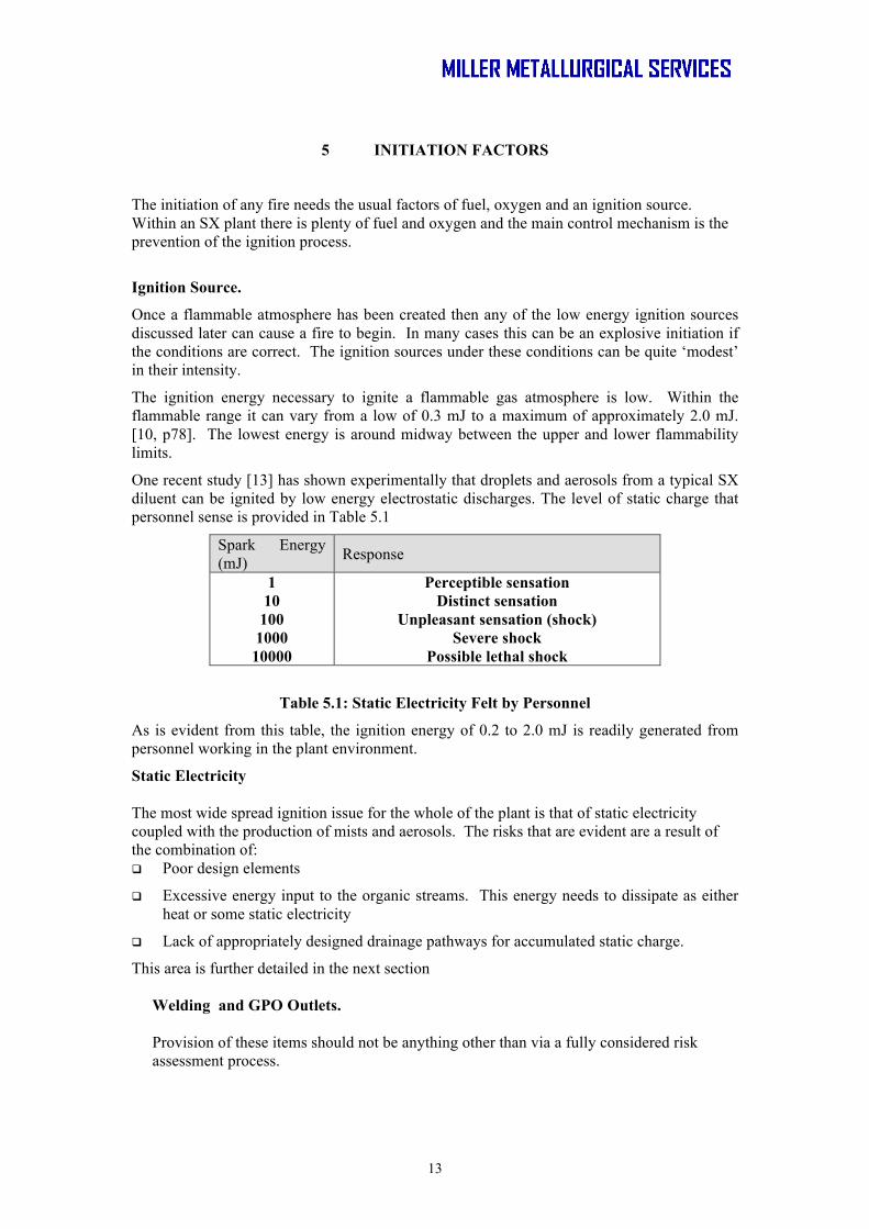
One recent study [13] has shown experimentally that droplets and aerosols from a typical SX diluent can be ignited by low energy electrostatic discharges. The level of static charge that personnel sense is provided in Table 5.1
Spark Energy (mJ) Response
1 Perceptible sensation 10 Distinct sensation
100 Unpleasant sensation (shock) 1000 Severe shock
10000 Possible lethal shock
Table 5.1: Static Electricity Felt by Personnel
As is evident from this table, the ignition energy of 0.2 to 2.0 mJ is readily generated from personnel working in the plant environment.
Static Electricity
The most wide spread ignition issue for the whole of the plant is that of static electricity coupled with the production of mists and aerosols. The risks that are evident are a result of the combination of: Poor design elements
Excessive energy input to the organic streams. This energy needs to dissipate as either heat or some static electricity
Lack of appropriately designed drainage pathways for accumulated static charge.
This area is further detailed in the next section
Welding and GPO Outlets. Provision of these items should not be anything other than via a fully considered risk assessment process.
14
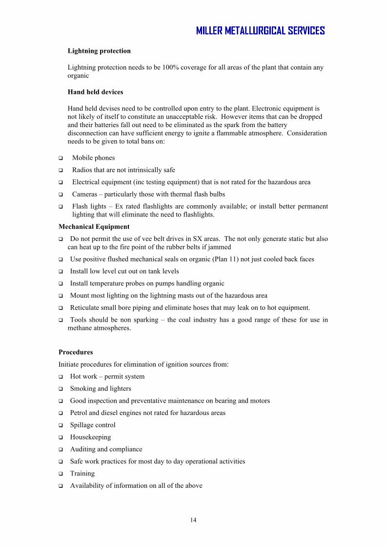
Lightning protection Lightning protection needs to be 100% coverage for all areas of the plant that contain any organic Hand held devices Hand held devises need to be controlled upon entry to the plant. Electronic equipment is not likely of itself to constitute an unacceptable risk. However items that can be dropped and their batteries fall out need to be eliminated as the spark from the battery disconnection can have sufficient energy to ignite a flammable atmosphere. Consideration needs to be given to total bans on:
Mobile phones
Radios that are not intrinsically safe
Electrical equipment (inc testing equipment) that is not rated for the hazardous area
Cameras – particularly those with thermal flash bulbs
Flash lights – Ex rated flashlights are commonly available; or install better permanent lighting that will eliminate the need to flashlights.
Mechanical Equipment
Do not permit the use of vee belt drives in SX areas. The not only generate static but also can heat up to the fire point of the rubber belts if jammed
Use positive flushed mechanical seals on organic (Plan 11) not just cooled back faces
Install low level cut out on tank levels
Install temperature probes on pumps handling organic
Mount most lighting on the lightning masts out of the hazardous area
Reticulate small bore piping and eliminate hoses that may leak on to hot equipment.
Tools should be non sparking – the coal industry has a good range of these for use in methane atmospheres.
Procedures
Initiate procedures for elimination of ignition sources from:
Hot work – permit system
Smoking and lighters
Good inspection and preventative maintenance on bearing and motors
Petrol and diesel engines not rated for hazardous areas
Spillage control
Housekeeping
Auditing and compliance
Safe work practices for most day to day operational activities
Training
Availability of information on all of the above

15
6 CONTROL OF STATIC ELECTRICITY
Static Generation
The static electricity issues are significant for plants handling hydrocarbon liquids. There are relevant Australian and international standards [14] for designing process plants to eliminate or minimise the generation of static charge. Mechanisms also need to be included to dissipate (drain or earth) any static charge that is created. Recommendations for grounding are contained in all the standards.
One important factor that is not generally considered is the generation of static in the separation process occurring in a settler. As the particles separate they can form static charge as they slip past each other. The presence of aqueous entrainment in the hydrocarbons is also a high generator of static charge as these droplets can create significant charge through their movement within the non conducting hydrocarbon. The lower the conductivity of the aqueous the greater is the generation of static electricity. The use of demineralised water for washing/scrubbing operations should not be contemplated; unless its conductivity is increased with the addition of acid or electrolyte.
Other charge generation occurs when any relative movement takes place. The higher the velocity and the greater the turbulence; the greater the charge generation. Activities that can generate static include:
Mixing of droplets
Mixing or settling of solids
Disruption of an interface
Atomisation
Splashing
Flow past a fixed boundary eg pipe or vessel wall
Conductivity enhancement chemicals are available; particularly for the aeroplane fuels. These increase the conductivity of the hydrocarbon to levels where the static generation is minimised and dissipation is faster [13]. However there have been no plant trials as there appears to be significant adverse effects on the phase separation process in the SX process.
The range of liquid conductivities, over which static charge generation is experienced, is 10-1 to 105 pS/m. The maximum occurs with liquid conductivity of the order of 10 pS/m. the higher the conductivity the faster the generated charge flows to earth. It is unlikely that electrostatic discharge will occur for metal containers or pipes with liquid conductivities greater than 200 pS/m [13].
Some typical plant results for liquid conductivities are: New diluent 1.0 pS/m
Extractant (copper) 25 – 50 pS/m
In circuit organic 80 – 200 pS/m
In circuit organic (high metal loading) >1 000 pS/m
Simple spark discharge is common from conductive surfaces once an accumulated charge is grounded. However non conductive surfaces can discharge multiple times (brush discharge) as the charges on the non conducting surface have no mobility to the grounding point.

16
Removal of Static Charge
Conductive surfaces when grounded do not accumulate charge as the conduction allows the charge to be removed. There has been a move recently to provide conductive surfaces on FRP pipes and vessels to allow this charge removal to occur. ODO has led the way in this regard. However where lower grade stainless steel (316/316L) can be utilised for vessel fabrication, there is much greater opportunity for static charge grounding. In chemical environments where metal is not an economic option the use of conductivity enhanced FRP is a viable option adding only 10% to 15% to the overall cost of the FRP.
However ungrounded (isolated) conductors (such as valves or instruments) can cause very high potentials to accumulate (up to tens of kilovolts). This can cause a brush discharge if the pipe or local volume is not full of liquid.
Charge dissipation in tanks is a function of whether the tank bottom can be grounded. If this is achieved then charge relaxation times (time to reach 1/e = 37% of its starting value) of less than one second can be achieved.
Minimisation of Static Generation
Poor design elements are departures from the code of practice for control of static electricity. The major issues are:
High level entries into tanks (loaded and/or stripped organic tanks)
Free fall of organic from inlets to final levels with fall through surfaces (organic tanks and settler organic launders, coalescer overflow weirs etc)
Excessive pipe velocities in organic lines from either/or/both pipe size too small or excessive available gravity head.
Entrainment of air into the mixers and subsequent separation in the settlers
Entrainment of low conductivity aqueous in organic streams from washing and scrubbing settlers
Most of these can be addressed to a greater or lesser extent with alternate equipment design:
Tank entries at a lower level to keep the entry submerged
Operation of weirs and discharge launders at high levels to minimise free fall heights.
In order to keep the incident vertical velocity to <1 m/s the free fall height in organic collection launders needs to be less than 50 mm.
Provision of control valves to dissipate the available head in a controlled manner.
The excess energy input to the organic has some limited opportunities for redress.
The free fall into the tank farm area needs to minimised as illustrated in Figure 6.1

17
Figure 6.1: Low Head Difference Between SX and Tank-Farm
Extra energy added from any low hydraulic efficiency pump mixer and axial flow impellors. Modern high efficiency units should be used. This is also an issue with aerosol production .
Any design feature that may induce energy dissipation needs to be redesigned and removed.
High pressure cleaning using > 1 MPa should not be used at it constitutes a risk of introducing static electricity via the high velocity nozzles used in the water blaster.
Other sources of static charge are from personnel wearing PPE that can generate such charges. Non conductive artificial fibres are good for acid resistance but are also good generators of static electricity. Serious considerations should be given to changing the PPE requirement for the SX plant to cotton rather than polyester.
Drainage of the static charge needs to be integrated into the plant and vessel design.
Relaxation (dissipation) of the static requires both extended times and large areas of contact to achieve low voltages. This is best achieved with conductive vessels (and vessel internals). In all cases the conductive elements are to be earthed to dissipate the static charge.
Loaded organic and coalescers tanks:
− Line coalescers with conductive FRP veils − Line loaded organic tank with conductive FRP − Pipes to and from coalescers to be conductive FRP − Locate the tank feed to the bottom and select appropriate size − Add an aqueous entrainment transfer pump to remove de-entrained aqueous from
the organic tank − Use of graphite conductive valves for flow control and energy dissipation.
SX intra plant organic pipes – use conductive FRP
SX settlers:
− Fit feed distributor vanes in conductive FRP − Use picket fences with non spouting design in conductive FRP

18
− Organic weir use curved smooth flow weir in conductive FRP − Line with conductive FRP
SX mixers:
− Line with conductive FRP − Use high efficiency mixers
All of these elements are simply application of the relevant standards on minimisation and dissipation of static electricity. It is not rocket science and it is easy to do correctly. So often the plant layout is driven by other factors that are perceived to be more important. However the incidents at Olympic Dam have shown that static electricity is probably the most important ignition source that must be addressed by the design engineers.

19
7 FUEL CONTROL FACTORS
There are two fuel requirements for a fire. That needed in the initiation process to form the flammable atmosphere; and that required to sustain the fire in the longer term. Elimination of either or both of these fuel sources will break the fire scenario.
Fuel for initiation
The fuel for initiation needs to be in a form that can be readily ignited, and then maintained long enough for the local fire to escalate to involve the large settler pools. The presence of mists and vapours is a major source of potential ignitable fuel that can maintain a fire for the requisite period.
One of the easiest fuel control steps is to eliminate the atmosphere of droplets and aerosols that can form in partially full pipes. By keeping the pipes full there is no opportunity for an explosive atmosphere to form and minimal risk of ignition from any static charge generated.
All points where mists, vapours and aerosols are produced should be eliminated or minimised. Some of these aerosols are produced in prodigious amounts from:
Stripped and loaded organic tanks if not fed correctly at the bottom
Organic feed siphon break tanks
Settler feed systems that induce turbulence
Settler organic discharge launders
Entrainment of air into mixers and subsequent release with entrained aerosols
Priority activities need to be directed towards the elimination and minimisation of aerosols in the plant. This will minimise the continuous availability of the ignition fuel sources. Limiting fire time.
The fuel supply for any initiated fire is very large. Experience from other SX and large hydrocarbon fires is that removal of the fuel is a good method of limiting the time that the fire is able to damage assets. A fuel dump system from the process vessels could be integrated with a bund overflow handling system; with storage in a modified environmental containment structure.
Vessel dump systems were an integral part of SX plants in the 70’s and early 80’s but have not been incorporated in recent times. Other operations with dump systems include Olympic Dam (retro-fitted) and Ranger Uranium (original design). New projects have included these systems as part of the overall risk management process.
Fire escalation scenario development planning is required to fully assess the effectiveness and timing required for a vessel dump system. This should be undertaken as a matter of course so that appropriate planning and design can be put in place. A fire plume analysis will be required to allow assessment of the time required to involve a near by settler from spontaneous ignition.
An integrated dump system with the bund overflow control system will minimise the cost impacts from separate systems.
Once decisions regarding the inclusion of dump system are made the implementation can become part of the larger issues of production continuity planning, settler long term maintenance, static electricity dissipation and operational performance. By integrating all of

20
these functions a single coherent plan can be put in place with only one set of required outcomes.

21
8 FIRE PLUME AND RADIANT HEAT ISSUES
The fire plume and radiant heat release are important factors in analysing:
The other assets that are at risk of being included in the fire
The placement of control facilities (valves, foam tanks etc) so that they are serviceable in a fire event
The distance that personnel can get to the seat of the fire for extinguishment activities.
A typical heat flux for a pool fire of 10 m diameter is shown in the Figure 8.1 for gasoline [12]. The lines represent different models used for fire plume.
(a) point source
(b) flame as a vertical rectangle
(c) from a correlation of Shokri and Beyler of experimental data. They recommend a factor of safety of x2 to ensure that all data points are included. This indicates that the simple point source model can be used with some accuracy for first round approximations of heat flux from medium sized pool fires.
Figure 8.1: Heat Flux Models for Larger Pool Fires
The presence of a wind can severely distort the fire plume and extend the radiant zone down wind for a significant distance. A wind of 2 m/s (7.2 km/h) will distort the fire plume to 45 degrees. For open areas such as a settler fire the fire will tend to hug the ground for a distance of 0.5D down wind as well. [11, p145]. Both effects increase the exposure of down wind assets to the radiant heat flux.
In general the surface of the burning liquid is close to but just below its boiling point. For liquid mixtures the lower boiling fractions will tend to burn off first. The use of a tight boiling range diluent also has the benefit of limiting the liquid surface temperature as the fire progresses.
22
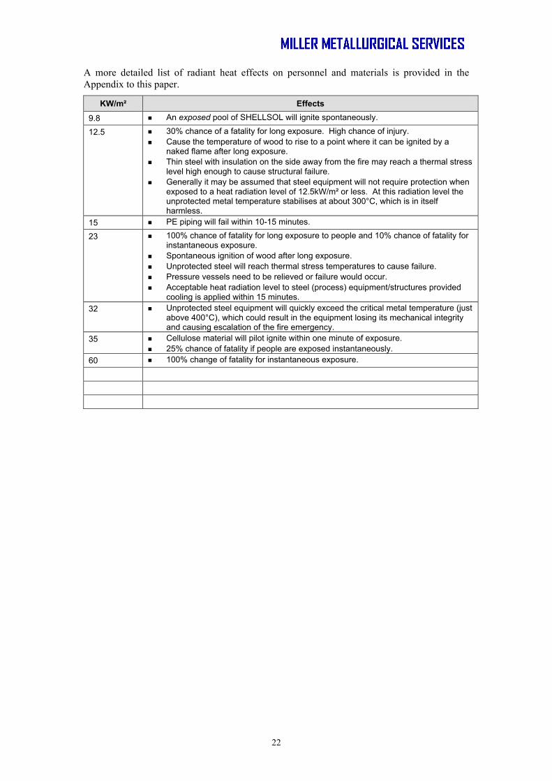
A more detailed list of radiant heat effects on personnel and materials is provided in the Appendix to this paper.
KW/m² Effects
9.8 An exposed pool of SHELLSOL will ignite spontaneously.
12.5 30% chance of a fatality for long exposure. High chance of injury. Cause the temperature of wood to rise to a point where it can be ignited by a
naked flame after long exposure. Thin steel with insulation on the side away from the fire may reach a thermal stress
level high enough to cause structural failure. Generally it may be assumed that steel equipment will not require protection when
exposed to a heat radiation level of 12.5kW/m² or less. At this radiation level the unprotected metal temperature stabilises at about 300°C, which is in itself harmless.
15 PE piping will fail within 10-15 minutes.
23 100% chance of fatality for long exposure to people and 10% chance of fatality for instantaneous exposure.
Spontaneous ignition of wood after long exposure. Unprotected steel will reach thermal stress temperatures to cause failure. Pressure vessels need to be relieved or failure would occur. Acceptable heat radiation level to steel (process) equipment/structures provided
cooling is applied within 15 minutes. 32 Unprotected steel equipment will quickly exceed the critical metal temperature (just
above 400°C), which could result in the equipment losing its mechanical integrity and causing escalation of the fire emergency.
35 Cellulose material will pilot ignite within one minute of exposure. 25% chance of fatality if people are exposed instantaneously.
60 100% change of fatality for instantaneous exposure.

23
9 EXTINGUISHMENT
Liquid hydrocarbon fires can be extinguished with foam, dry chemical agents, carbon dioxide, hologenated agents or water (with special fine mist applicators) [ 11 ch 6, p8-1].
The typical foam is an Aqueous Film Forming Foam (AFFF) which spreads across the liquid surface excluding the air; and preventing the vapour from mixing with the air. As such it needs to cover the entire surface of the liquid until the fire is extinguished. There is no current theory for the performance of foams and their characteristics need to be measured under standard conditions.
The point to keep in mind with foams is that they do drain and collapse both by film drainage and from evaporation of the film from the heat of the fire. Further foam loss can occur from entrainment in turbulent air or violent up-rising combustion gases. As a result foam needs to be replenished if the foam application does not immediately extinguish the flame. The drainage characteristic also implies that the foam will in time drain and expose the surface of the liquid to further possible ignition. This ‘burn back’ is also measured as a foam characteristic; and is generally in the region of 10 to 15 minutes, after the initial 5 minute application has ceased. [12, p 4-89]. The efficacy of foam is greater the sooner it is applied (especially to larger areas) a rapid-response detection system is recommended for initiation of a foam application. The aim is for liquid hydrocarbon fires to achieve a fire control time of 30 s and an extinguishment time of 60 s. For this reason alone the use of thermally activated systems can not be recommended for SX plants.
The foam application rate can be tailored to suit the particular solvent being considered. Lower applications are possible with higher flash point fuels.. However control and extinguishment times increase as a result. Typical application rates range from 1.6 L/min/m2 to 6.6 L/min/m2. The lower rates being more applicable to smaller spill fires in open locations such as air craft carrier flight decks. [12, ch 4, p 4-109].
If a foam system is selected for use then it needs to be of such a size and capacity that it can blanket the vessel in as short a time as possible – and maintain it for the required time to ensure extinguishment. For this reason multiple applicators are used on large settlers where the area is substantial. It is often possible to foam blanket a modest settler (less than 200 m2) within a few seconds.
As was evident from the ODO experience once a fire is set in a very large area there is little that can be done to extinguish it until the fuel has been consumed. The foam blanketing used did limit the active area of the fire (and thus helped to preserve some of the assets) but did little to actually extinguish it.
Much of the focus of conventional fire control is on the extinguishment step in the overall process. Using the sorts of analysis tools that are now available it is possible to review this focus and replace it with one based on a combination of:
Fuel reduction
Cooling and protection of other assets
Prevention of escalation by bunding, enclosure (and cooling)
Fast response knock down systems (foam or water mist sprays)
Escalation scenario development and identification of high priority outcomes.
This latter tool is more fully explored in the next section
24
10 ESCALATION SCENARIOS ANALYSIS
Steel containers exposed to a liquid pool fire (without sprinkler protection) can fail structurally between two and eight minutes [x12, chap 4, p 4-115]. This period is very short in terms of getting external fire extinguishment systems initiated. The consequences of this are alarming and require significant ability to react quickly:
Use of fast response detection systems
Use of fuel minimisation strategies (ie dump system to a remote storage)
Short fire life even of steel vessels and tanks
The need for automatic systems that can respond rapidly to all the actions required – foam/water application, fuel dump, cooling of other local assets.
As a result of the short time periods, it is important to explore the various scenarios that can develop during a fire event.
A fire plume analysis will indicate which other assets may be at risk from the radiant energy from the very large fire plume. It is likely that the following assets can be at significant radiation risk. Adjacent settlers
All the above ground fire water reticulation
All near by foam addition systems
Manual monitor stations
Pipe rack between the SX and tank farms
Further information from a fire plume analysis will indicate if cooling water spray / curtains would be effective (and for how long) for protection of near by settlers and other assets. From this analysis will arise an alternate asset protection / preservation plan that takes into account the very large fire plume likely to result from an SX fire. Some of the more ‘normal’ systems may be found to be of little value including: Manual monitor stations
Over the settler deluge spray systems
Total foam storage volume (in the light of experience from other fires)
The use of fire suppression and cooling water will place a significant load on the process bunding system. As such the disposal of the fire water becomes an integral part of the bund design and selection process. Without adequate bund overflow and containment systems uncontrolled overflow can occur with resultant running pool fires. These were responsible to a large degree in the escalation of the fires at ODO and Rossing. A similar situation did not seem to rise at Morenci and further information would be welcome as to the reasons.
Systems Failure Risks There are a number of risks of systems failures for operation of an SX plant. An in depth review of the systems in place needs to be undertaken to assess their effectiveness and the internal control and QA audit mechanisms in place.

25
Other potential issues are: Need of an emergency response team coordinator
Need for operationally experienced personnel on the emergency response team
Need for fluid isolation valve location information
Need for known and easy access to the emergency response plan
Need for emergency scenario developments and related response plans (the fight or flight decisions)
All of these items form an integral part of the systems needed to minimise risk and respond adequately to an incident.

26
11 MINIMISING BUSINESS INTERRUPTION
One of the largest consequences of an SX plant fire is the resultant business interruption. There is both the cost of replacing the facility and the lost production. This latter can be an order of magnitude more than the plant physical capital. As a result one of the more effective management tools available is to integrate a business interruption plan with the plant design process. Alternatively for an existing operation the interruption planning process can identify investment opportunities that will minimise the business interruption.
As was evident from the experiences of the known significant SX fires the ability to get back into production quickly is a key part of the minimisation strategy. This was achieved by: Rossing - having the SX split into two separate trains. One of which could
be preserved and maintain a high level of production.
Morenci - preserving part of the SX plant and being able to reconfigure it to maximise production.
Olympic Dam - having a second SX circuit that could be reconfigured to maximise production
This is in stark contrast to Mariquita and Gulf Chemicals where production loss was 100% until the plant was rebuilt.
A number of new projects have considered the business interruption (BI) planning process as an integral part of the engineering design of the plant. The BI analysis has highlighted the benefits of:
Use of multiple SX trains to preserve a production capability
Ability to reconfigure the remaining SX assets to maximise production
Preservation of as many assets as possible both internal and external to the SX plant.
Provision of plant separations
Primary: - SX train to SX train,
- SX area to EW and other plant sections,
- Electrolyte and crud treatment areas separate to SX tank-farms
Secondary: - Mixer-settlers to tank farm within a train.
Fire break spools in all plastic piping crossing separation areas.
Automatic cooling of nearby assets – especially other mixer-settlers. This requires that the fire be prevented from spreading by an ability to cool other assets within the fire plume
Fire hydrants or monitors for cooling near by assets.
Systems to handle the fire fighting and cooling water applied, to prevent creating running pool fires.
Provision of a remote emergency dump area where a running pool fire could be directed.
Provision of a remote dump area where vessel contents could be stored / removed from immediate fire danger.
Implementation of these measures has been included in three or four recent projects without major capital cost impact. By using the BI planning process the plant layout was changed to include these facilities without incurring extra costs.

27
The biggest impact on fire development is the physical separation of the SX plant and the trains with it. All this needs is some extra piping.
The provision of remote dump and fire water control ponds can be integrated with the overall site drainage and environmental management structures. There is no reason why the environmental dam can not do double duty.
The targeted provision of cooling systems is no more than is generally required for the fire fighting system in any case. Once again the fire system can perform two functions from the same reticulation. The only cost increase is a few more control valves to be able to more easily service the appropriate target.
Another recent project has included these aspects into a brown fields upgrade of their SX plants. The additional provisions on the site were:
the dump ponds and
the improved and targeted fire/cooling water reticulation.

28
12 CONCLUSIONS
The main SX fires have highlighted a number of failures of engineering and procedural controls. All these are well known in the hydrocarbon industries and need to be better appreciated in the mineral processing industries.
Fire prevention should be a paramount focus of SX plant design. This needs to include all the aspects of fuel supply, generation of flammable atmospheres, minimisation of static electricity and elimination of other ignition sources.
Many engineering companies have failed to ensure that all the available tools, standards and knowledge have been utilised in the design process. Some plants have been built without reference to even the most basic standards that should be in the toolkit of all designers.
Fire plume analysis and escalation scenario development are key tools in the understanding and minimisation of fire risk for SX plants. Both can provide significant benefits in eliminating risks (such as uncontrolled running pool fires) and involvement of other assets in a fire.
Business interruption planning needs to be made an integral part of the engineering control process. This ensures that the physical plant can be used after a fire event to maximise production and minimise the loss of cash flow.
Engineering controls are not enough for fire risk management. A strict system of risk management procedures and work descriptions needs to be in place and their use enforced and built into the site culture.
A significant number of SX plant fires can be traced to one or more failures of the operational management controls. Mostly this is related to a culture that is not focused on risk identification and removal but rather adherence to set protocols that become burdensome and observed more in the breach.

29
13 REFERENCES
1.0 South Australian Metropolitan Fire Service, 2002?, ‘Investigation into a fire which occurred at Copper and Uranium Plant SX, 21st October 2001, Olympic Dam Copper/Uranium Mine, Roxby Downs , South Australia”, undated.
2.0 Miller GM, ‘Presentation on Solvent Extraction Fires’, Miller Metallurgical Services, Brisbane, 2005.
3.0 Bateman Engineering LIX Users conference
4.0 McKenzie M, 2004, Private Communication
5.0 McKenzie M, 2004, Private Communication
6.0 Sylvester C, 2003, Private Communication
7.0 Kessler S, 2004, Private Communications.
8.0 Goodman D, 1990, Private Communication
9.0 Alexander D, 2004, Private Communication
10.0 Drysdale D “ An Introduction to Fire Dynamics”, 2nd Ed, John Wiley & Sons.
11.0 NFPA Fire Protection Handbook Nineteenth Edition Vol 1
12.0 NFPA Fire Protection Handbook Nineteenth Edition Vol 2
13.0 Wolfson Electrostatics, 2004, ‘ Electrostatic Ignition Hazards in Copper Solvent Extraction (SX) Processes at Cerro Colorado and Escondida Oxide’, Report No. 374/GLH, 22/10/2004.
14.0 AS/NZS 1020: The Control of Undesirable Static Electricity, Australian Standards, 1995

30
14 APPENDIX
Heat and Thermal Radiation Consequences
Consequences of Heat Radiation
KW/m² Effects
1.2 Received from the sun at noon in summer.
2.1 Minimum to cause pain in one minute.
4.7 Will cause pain in 15-20 seconds and injury after 30 seconds exposure (at least second degree burns will occur).
9.8 An exposed pool of SHELLSOL will ignite spontaneously.
12.5 30% chance of a fatality for long exposure. High chance of injury. Cause the temperature of wood to rise to a point where it can be ignited by a
naked flame after long exposure. Thin steel with insulation on the side away from the fire may reach a thermal stress
level high enough to cause structural failure. Generally it may be assumed that steel equipment will not require protection when
exposed to a heat radiation level of 12.5kW/m² or less. At this radiation level the unprotected metal temperature stabilises at about 300°C, which is in itself harmless.
15 PE piping will fail within 10-15 minutes.
23 100% change of fatality for long exposure to people and 10% change of fatality for instantaneous exposure.
Spontaneous ignition of wood after long exposure. Unprotected steel will reach thermal stress temperatures to cause failure. Pressure vessels need to be relieved or failure would occur. Acceptable heat radiation level to steel (process) equipment/structures provided
cooling is applied within 15 minutes. 32 Unprotected steel equipment will quickly exceed the critical metal temperature (just
above 400°C), which could result in the equipment losing its mechanical integrity and causing escalation of the fire emergency.
35 Cellulose material will pilot ignite within one minute of exposure. 25% change of fatality if people are exposes instantaneously.
60 100% change of fatality for instantaneous exposure.

31
Thermal Radiation Hazard to People How long can a worker continue to operate in an emergency situation whilst exposed to a given level of heat radiation?
API-521. Values for time to pain for exposed bare skin
Radiation Level (kW/m²)
Time to pain (seconds)
1.74 60 2.33 40 2.9 30
4.73 16 6.94 9 9.46 6
11.67 4 19.87 2
API-521. Worker appropriately dressed and will not remain static during a task
Radiation Level (kW/m²) Conditions
1.58 Design flare heat release at any location where personnel are continuously exposed.
4.73 Heat intensity in areas where emergency actions lasting several minutes may be required by personnel without shielding but with appropriate clothing.
6.31 Heat intensity in areas where emergency actions lasting up to 1 minute may be required by personnel without shielding but with appropriate clothing.
9.46 Design flare heat release at any location to which people have access (eg. at grade below the flare or a service platform of a nearby tower).
15.77 Heat intensity on structures and in areas where operators are likely to be performing duties and where shelter from radiant heat is available (for eg. behind equipment).
Shell Research maximum design thermal radiation levels. Worker
appropriately dressed and will not remain static during a task.
Radiation Level (kW/m²) Exposure time limit
<1.5 Indefinite 1.5-1.8 Indefinite 2.2-3.0 15 minutes 3.0-4.0 5 minutes 4.0-6.3 1 minute 6.3-9.5 30 seconds
>9.5 Immediate
32
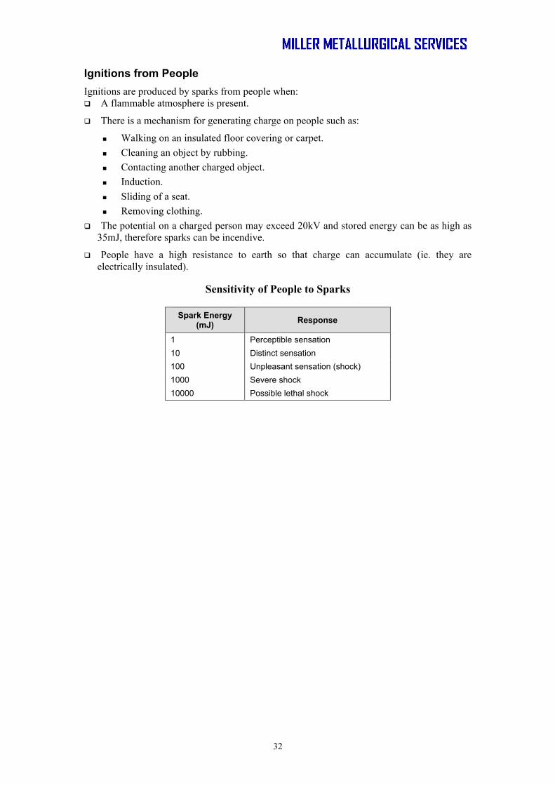
Ignitions from People Ignitions are produced by sparks from people when: A flammable atmosphere is present.
There is a mechanism for generating charge on people such as:
Walking on an insulated floor covering or carpet. Cleaning an object by rubbing. Contacting another charged object. Induction. Sliding of a seat. Removing clothing.
The potential on a charged person may exceed 20kV and stored energy can be as high as 35mJ, therefore sparks can be incendive.
People have a high resistance to earth so that charge can accumulate (ie. they are electrically insulated).
Sensitivity of People to Sparks
Spark Energy (mJ) Response
1 Perceptible sensation 10 Distinct sensation 100 Unpleasant sensation (shock) 1000 Severe shock 10000 Possible lethal shock