RIDUTTORE A VITE H HE LI CAL WORM GEAR - SENZA FINE …...RAL5010, whe re as tho se in alu mi nium...
19
57 57 57 4.0 RIDUTTORE A VITE SENZA FINE CON PRECOPPIA H H HELICAL WORM GEAR- BOXES STIRNRAD- SCHNECKENGETRIEBE H 4.1 Caratteristiche Characteristics Merkmale 58 4.2 Designazione Designation Bezeichnung 59 4.3 Lubrificazione e posizioni di montaggio Lubrication and mounting position Schmierung und Einbaulage 59 4.4 Posizione morsettiera Terminal board positions Lage der Klemmenkaste 60 4.5 Dati tecnici Technical data Technische Daten 61 4.6 Momenti d'inerzia Moments of inertia Trägheitsmoment 67 4.7 Dimensioni Dimensions Abmessungen 68 4.8 Esecuzione con vite bisporgente Double extended worm shaft design Versionen mit doppelseitig herausragender Schneckenwelle 72 4.9 Limitatore di coppia cavo passante Torque limiter with through hollow shaft Drehmomentbegrenzer mit durchgehender Hohlwelle 72 4.10 Accessori Accessories Zubehör 74 4.11 Lista parti di ricambio Spare parts list Ersatzteilliste 75
Transcript of RIDUTTORE A VITE H HE LI CAL WORM GEAR - SENZA FINE …...RAL5010, whe re as tho se in alu mi nium...
575757
4.0RIDUTTORE A VITE SENZA FINE CONPRECOPPIA H
H HE LI CAL WORM GEAR -BOXES
STIRNRAD-SCHNECKENGETRIEBE H
4.1 Caratteristiche Char ac ter is tics Merk male 58
4.2 Designazione Des ig na tion Bezeichnung 59
4.3 Lubrificazione e posizioni di montaggio
Lu bri ca tion andmount ing po si tion
Schmierung und Einbaulage
59
4.4 Posizione morsettiera Ter mi nal board po si tions Lage der Klemmenkaste 60
4.5 Dati tecnici Tech ni cal data Technische Daten 61
4.6 Momenti d'inerzia Mo ments of in er tia Trägheitsmoment 67
4.7 Dimensioni Di men sions Abmessungen 68
4.8 Esecuzione con vitebisporgente
Dou ble ex tended worm shaft de sign
Versionen mit doppelseitigherausragender Schneckenwelle
72
4.9 Limitatore di coppia cavo passante
Torque lim iter with through hol low shaft
Drehmomentbegrenzermit durchgehender Hohlwelle
72
4.10 Accessori Ac ces so ries Zubehör 74
4.11 Lista parti di ricambio Spare parts list Ersatzteilliste 75
585858
4.1 Characteristics 4.1 Merkmale4.1 Caratteristiche
• La se rie H pre sen ta le stes se ca rat te ri -sti che del la se rie X, ma la pre sen zadel la pre cop pia ci lin dri ca in en tra tacon sen te la re a liz za zio ne di rap por tipiù ele va ti o, a pa ri tà di rap por to, ren di -men ti mi glio ri.
• La strut tu ra è com po sta dal la car cas samo no bloc co del ri dut to re a vite serie XAsul l'en tra ta del qua le è fis sa to il cor pocon te nen te il pri mo sta dio di ri du zio ne.
• La vite sen za fine è in ac cia io le ga tocementato-tem pra to ed è ret ti fi ca ta.
• Gli in gra nag gi del la pri ma ri du zio nehan no den ta tu ra eli co i da le con pro fi loret ti fi ca to.
• La co ro na ha il moz zo in ghi sa con ri por -to di fu sio ne del l'a nel lo in bron zo.
• Vie ne for ni to l'al be ro usci ta cavo di se -rie ed esi ste un 'am pia di spo ni bi li tà diac ces so ri:se con da en tra ta, cu sci net ti co ni ci sul laco ro na, flan gia usci ta, al be ro len to con1 o 2 spor gen ze, li mi ta to re di cop piacon cavo pas san te, brac cio di re a zio -ne.
• Le car cas se in ghi sa sono ver ni cia teBLU RAL5010 men tre quel le in al lu mi -nio sono sab bia te.
• The H se ries has the same char ac ter is -tics as the X se ries with the ad di tion of aspur gear pre-stage at in put which pro -vides higher ra tios or better ef fi ciencyun der the same ra tios.
• The struc ture is com posed of a sin glepiece hous ing for the XA gear box , atthe in put side of this gear box is fit ted the hous ing con tain ing the first stage re duc -tion.
• The worm shaft is gro und and in case -and quenchhar de ned al loy ste el.
• The gears of the first re duc tion have ahe li cal toothing with ground pro file.
• The worm wheel has a cast-iron hubpro vided with in serted cast-bronze ring.
• Hol low out put shaft is sup plied as stan -dard. A bro ad ran ge of ac ces so ries isava i la ble: se cond in put, ta pe red rol ler be a rings onthe worm whe el, out put flan ge, sin gle ordo u ble ex tended out put shaft, tor que li -mi ter with thro ugh hol low shaft.
• Ho u sings in cast-iron are pa in ted BLUERAL5010, whe re as tho se in alu mi niumare sandbla sted.
• Die Se rie H bie tet die glei chen Ei gen -schaf ten wie die Se rie X. Auf grund derStirn rad-Vor stu fe bei der Se rie H sindje doch hö he re Un ter set zun gen mög lichoder man er hält bei glei chen Un ter set -zun gen ei nen bes se ren Wir kungs grad.
• Die se Aus füh rung be steht aus demBloc kge häu se des Schne cken ge trie -bes der Se rie XA und ei nem an den an -triebs sei tig an ge bau ten Ge häu se,wel ches die Stirn rad vor stu fe ent hält.
• Die Schnec ke ist aus ein sat zgehärt-etem/ab geschrec ktem und da ra uf hingeschlif fe nen Le gie rungsstahl.
• Die Zahn rä der der Vor stu fe be sit zen ein schräg ver zahn tes Stirn rad pro fil.
• Das Schne cken rad be steht aus ei nerNabe aus Guss ei sen und ei nem auf ge -schleu der ten Guss bron ze-Ring.
• Zah lre i ches Zu be hör ist lie fer bar: zwe i te Antrieb, Ke gel rol len la ger aufSchnec ken rad, Abtrieb sflansch, stan -dard oder dop pel se i tig he ra u sra gen deAbtrieb swel le, Drehmo men tbe gren zermit durchge hen der Wel le, Dreh mo -mentstütze.
• Geh äu se aus Gus se i sen wer den mitBLAU RAL5010 lac kiert, Geh äu se ausAlu mi nium wer den san dge strahlt.

595959
.to
m.tta.
so
psi
der
Pg
nilp
uo
c rot
oM
ss
ulh
cs
nar
oto
M
erott
udi
Rx
obr
ae
Ge
beirt
eG
atart
ne
opi
T Ie
pyt t
up
ntr
as
beirt
nA
a
zz
ed
nar
Gezi
Se
ßör
G
.tn
om i
d e
noi
zis
oP
noiti
so
p g
nitn
uo
Me
gal
ua
bni
E
.ai
pp
oc i
d er
otati
miL
reti
mil e
uqr
oT
-tn
em
om
her
Dr
ez
ner
ge
b
.dir
otro
pp
aR
oita
Rg
nu
zte
sret
nU
atic
su
ore
blA
fa
hs t
upt
uO
t elle
ws
beirt
bA
.ati
cs
u ni
aig
nal
Fe
gn
alf tu
ptu
Oh
cs
nalf
sb
eirtb
A
en
oiz
aer i
d oi
cc
arB
mra
eu
qro
Te
ztüt
stn
e m
o m
her
D
atart
ne
ad
no
ce
St
up
ni d
no
ce
Sb
eirtn
A reti
ew
Z
H A 50 30/1 P.A.M B3 F1S LD SeA H BR
4050637590
110
30406080
100 120 160 200 260 320 400
5663718090
100 112
B3, B6
B7, B8
V5, V6
F1D-F2D-F3D
F1S-F2S-F3S
F12-F22-F32
LD
LS
SeA
H
SD
SS
DD
BR
aip
po
cer
p n
oc
enif
az
ne
s eti
v a
erott
udi
Re
gat
s-er
p hti
w x
obr
ae
g mr
oW
efut
sro
V tim
eb
eirte
gn
ek
ce
nh
cS
F
A
4.2 Designation 4.2 Bezeichnung4.2 Designazione
4.3 Lubrication andmounting position
4.3 Schmierung undEinbaulage
4.3 Lubrificazione eposizioni di montaggio
FLS
LS
LD
FLD
FLS
LS
LD
LD
FLD
FLD
FLSFLS
FLS
LS
LS
LS
LD
FLD FLSLS
FLDFLD
LD
LD
B3 B6 B7 B8 V5 V6
I ridut to ri a vite sen za fine H sono for ni ticom ple ti di lu bri fi can te sin te ti co.Si rac co man da di pre ci sa re sem pre infase di or di ne, la po si zio ne di lavorodesiderata.
H se ries worm gear boxes are sup pliedwith syn thetic lu bri cant.Al ways spec ify the re quired mount ing po -si tion when or der ing.
Schne cken ge trie be Se rie H wer den mitsyn the ti schem Schmier mit tel ge lie fert.Im Auf trag bit te im mer die ge wünsch teEin bau la ge an ge ben.
Carico e sfiato / Filling and breather
Einfüll und Entlüftung
Livello / Level / Ölstand
Scarico / Drain / Ablass
Nei corpi in alluminio 40, 50, 63,75 è presente un solotappo di riempimento olio.
Aluminium housings size 40, 50, 63 and 75 have onefilling plug only.
Aluminiumgehäuse in den Größen 40, 50, 63 und 75haben nur eine Einfüllengsschraube
Tipo entrata Input type Antriebstyp
H ..A H ..F
606060
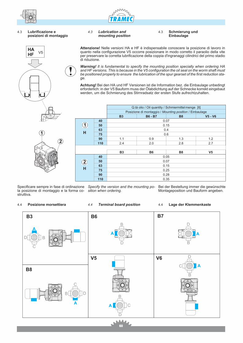
War ning! It is fun da men tal to spe cify the mo un ting po si tion spe cially when or de ring HAand HF ver sions. This is be ca u se in the V5 con fi gu ra tion the oil seal on the worm shaft must be po si tio ned pro perly to en su re the lu bri ca tion of the spur gearset of the first re duc tion sta -ge.
Achtung! Bei den HA und HF Ver sio nen ist die Infor ma tion bez. die Ein ba u la ge un be dingter for der lich: in der V5 Ba u form muss der Ölab dic htung auf der Schnec ke kor rekt ein ge ba utwer den, um die Schmie rung des Stir nradsatz der er sten Stu fe au frechtzu hal ten.
Atten zio ne! Nel le ver sio ni HA e HF è in di spen sa bi le co no sce re la po si zio ne di la vo ro inquan to nel la con fi gu ra zio ne V5 oc cor re po si zio na re in modo cor ret to il pa ra o lio del la viteper pre ser va re la cor ret ta lu bri fi ca zio ne del la cop pia d'in gra nag gi ci lin dri ci del pri mo sta diodi riduzione.
HAHF
V5
Q.tà olio / Oil quantity / Schmiermittel menge [lt]
Posizione di montaggio / Mounting position / Einbaulage
B3 B6 - B7 B8 V5 - V6
H
40 0.07
50 0.15
63 0.4
75 0.6
90 1.1 0.9 1.3 1.2
110 2.4 2.0 2.8 2.7
B3 B6 B8 V5
H
40 0.05
50 0.07
63 0.15
75 0.25
90 0.28
110 0.35
1
2
Spe ci fi ca re sem pre in fase di or di na zio nela po si zio ne di mon tag gio e la for ma co -strut ti va.
Bei der Be stel lung im mer die gewünschteMon ta ge po si tion und Ba u form an ge ben.
Spe cify the ver sion and the mo un ting po -si tion when or de ring.
1
2
AA
A
BB
B
C
C
C
D
A
B
C
D
D
D
B3
B8
B6 B7
V5 V6
A
B
C
D
A
B
D
C
4.4 Terminal board position 4.4 Lage der Klemmenkaste4.4 Posizione morsettiera
4.3 Lubrication andmounting position
4.3 Schmierung undEinbaulage
4.3 Lubrificazione eposizioni di montaggio
616161
40
n1 = 900 HF HA
inn2 T2 P1
FS'Input - IEC T2M P
Rd Pt0[min-1] [Nm] [kW] [Nm] [kW]B5 B14
30 30 31 0.13 2.1
— 63 56 — 63 56
66 0.27 0.76
—
40 23 40 0.13 1.6 66 0.21 0.7360 15 56 0.13 1.2 66 0.15 0.6780 11 49 0.09 1.3 66 0.12 0.64
100 9 58 0.09 1.0 58 0.09 0.59120 8 62 0.09 1.1 66 0.10 0.54160 6 51 0.06 1.3 66 0.08 0.50200 5 57 0.06 1.1 61 0.06 0.44
2.9 260 4 33 0.03 1.6 54 0.05 0.40320 3 39 0.03 1.2 46 0.03 0.39400 2 46* 0.03 0.7* 34 0.02 0.36
40
n1 = 2800 HF HA
inn2 T2 P1
FS'Input - IEC T2M P
Rd Pt0[min-1] [Nm] [kW] [Nm] [kW]B5 B14
30 93 30 0.37 1.7
— 63 56 — 63 56
52 0.64 0.80
—
40 70 39 0.37 1.4 53 0.50 0.7760 47 37 0.25 1.4 53 0.36 0.7280 35 47 0.25 1.1 50 0.26 0.70
100 28 40 0.18 1.1 44 0.20 0.65120 23 45 0.18 1.2 55 0.22 0.61160 18 40 0.13 1.3 52 0.17 0.57200 14 47 0.13 1.0 47 0.13 0.51
2.9 260 11 38 0.09 1.1 42 0.10 0.47320 9 44 0.09 0.9 39 0.08 0.45400 7 52* 0.09 0.6* 31 0.05 0.42
40
n1 = 1400 HF HA
inn2 T2 P1
FS'Input - IEC T2M P
Rd Pt0[min-1] [Nm] [kW] [Nm] [kW]B5 B14
30 47 35 0.22 1.9
— 63 56 — 63 56
65 0.41 0.77 0.6040 35 45 0.22 1.5 65 0.32 0.75 0.6060 23 62 0.22 1.0 62 0.23 0.69 0.5080 18 47 0.13 1.3 60 0.17 0.66 0.40
100 14 46 0.11 1.1 52 0.12 0.61 0.40120 12 60 0.13 1.1 66 0.14 0.57 0.30160 9 62 0.11 1.0 62 0.11 0.52 0.30200 7 58 0.09 1.0 58 0.09 0.47 0.30
2.9 260 5 46 0.06 1.1 46 0.06 0.43 0.20320 4 53 0.06 0.8 44 0.05 0.41 0.20400 3 64* 0.06 0.5* 33 0.03 0.38 0.20
40
n1 = 500 HF HA
inn2 T2 P1
FS'Input - IEC T2M P
Rd Pt0[min-1] [Nm] [kW] [Nm] [kW]B5 B14
30 17 — — —
— 63 56 — 63 56
66 0.15 0.74
—
40 13 — — — 66 0.12 0.7160 8 — — — 66 0.09 0.6680 6 — — — 66 0.07 0.62
100 5 — — — 66 0.06 0.57120 4 — — — 66 0.06 0.52160 3 — — — 66 0.04 0.48200 2.5 — — — 66 0.04 0.42
2.9 260 2 — — — 60 0.03 0.38320 1.5 — — — 48 0.02 0.36400 1 — — — 35 0.01 0.34
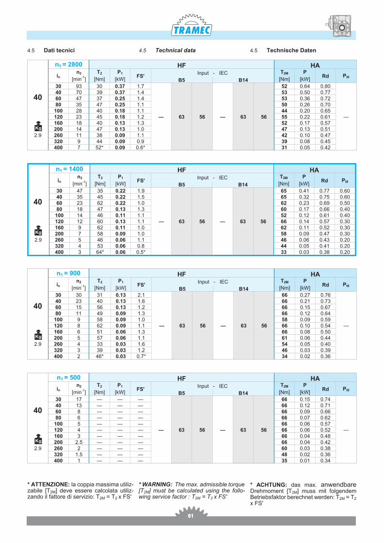
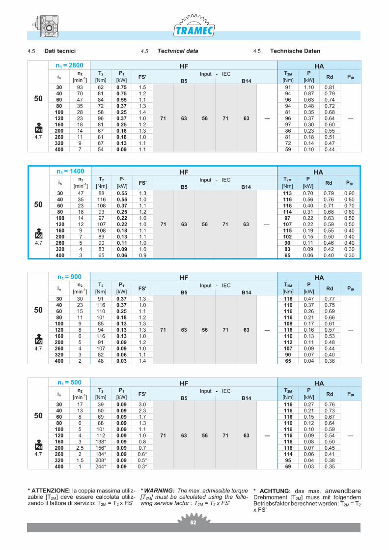
4.5 Technical data 4.5 Technische Daten4.5 Dati tecnici
* ATTENZIONE: la cop pia mas si ma uti liz -za bi le [T2M] deve es se re cal co la ta uti liz -zan do il fat to re di ser vi zio: T2M = T2 x FS'
* WARNING: The max. ad mis si ble tor que [T2M] must be cal cu la ted using the fol lo -wing ser vi ce fac tor : T2M = T2 x FS'
* ACHTUNG: das max. an wen dba reDreh mo ment [T2M] muss mit fol gen demBe trieb sfak tor be rec hnet wer den: T2M = T2
x FS'
Kg
Kg
Kg
Kg
626262
50
n1 = 900 HF HA
inn2 T2 P1
FS'Input - IEC T2M P
Rd Pt0[min-1] [Nm] [kW] [Nm] [kW]B5 B14
30 30 91 0.37 1.3
71 63 56 71 63 —
116 0.47 0.77
—
40 23 116 0.37 1.0 116 0.37 0.7560 15 110 0.25 1.1 116 0.26 0.6980 11 101 0.18 1.2 116 0.21 0.66
100 9 85 0.13 1.3 108 0.17 0.61120 8 94 0.13 1.3 116 0.16 0.57160 6 116 0.13 1.0 116 0.13 0.53200 5 91 0.09 1.2 112 0.11 0.48
4.7 260 4 107 0.09 1.0 107 0.09 0.44320 3 82 0.06 1.1 90 0.07 0.40400 2 48 0.03 1.4 65 0.04 0.38
50
n1 = 2800 HF HA
inn2 T2 P1
FS'Input - IEC T2M P
Rd Pt0[min-1] [Nm] [kW] [Nm] [kW]B5 B14
30 93 62 0.75 1.5
71 63 56 71 63 —
91 1.10 0.81
—
40 70 81 0.75 1.2 94 0.87 0.7960 47 84 0.55 1.1 96 0.63 0.7480 35 72 0.37 1.3 94 0.48 0.72
100 28 58 0.25 1.4 81 0.35 0.68120 23 96 0.37 1.0 96 0.37 0.64160 18 81 0.25 1.2 97 0.30 0.60200 14 67 0.18 1.3 86 0.23 0.55
4.7 260 11 81 0.18 1.0 81 0.18 0.51320 9 67 0.13 1.1 72 0.14 0.47400 7 54 0.09 1.1 59 0.10 0.44
50
n1 = 1400 HF HA
inn2 T2 P1
FS'Input - IEC T2M P
Rd Pt0[min-1] [Nm] [kW] [Nm] [kW]B5 B14
30 47 88 0.55 1.3
71 63 56 71 63 —
113 0.70 0.79 0.9040 35 116 0.55 1.0 116 0.56 0.76 0.8060 23 108 0.37 1.1 116 0.40 0.71 0.7080 18 93 0.25 1.2 114 0.31 0.68 0.60
100 14 97 0.22 1.0 97 0.22 0.63 0.50120 12 107 0.22 1.0 107 0.22 0.59 0.50160 9 108 0.18 1.1 115 0.19 0.55 0.40200 7 89 0.13 1.1 102 0.15 0.50 0.40
4.7 260 5 90 0.11 1.0 90 0.11 0.46 0.40320 4 83 0.09 1.0 83 0.09 0.42 0.30400 3 65 0.06 0.9 65 0.06 0.40 0.30
50
n1 = 500 HF HA
inn2 T2 P1
FS'Input - IEC T2M P
Rd Pt0[min-1] [Nm] [kW] [Nm] [kW]B5 B14
30 17 39 0.09 3.0
71 63 56 71 63 —
116 0.27 0.76
—
40 13 50 0.09 2.3 116 0.21 0.7360 8 69 0.09 1.7 116 0.15 0.6780 6 88 0.09 1.3 116 0.12 0.64
100 5 101 0.09 1.1 116 0.10 0.59120 4 112 0.09 1.0 116 0.09 0.54160 3 138* 0.09 0.8 116 0.08 0.50200 2.5 156* 0.09 0.7 116 0.07 0.45
4.7 260 2 184* 0.09 0.6* 114 0.06 0.41320 1.5 208* 0.09 0.5* 95 0.04 0.38400 1 244* 0.09 0.3* 69 0.03 0.35
* ATTENZIONE: la cop pia mas si ma uti liz -za bi le [T2M] deve es se re cal co la ta uti liz -zan do il fat to re di ser vi zio: T2M = T2 x FS'
* WARNING: The max. ad mis si ble tor que [T2M] must be cal cu la ted using the fol lo -wing ser vi ce fac tor : T2M = T2 x FS'
* ACHTUNG: das max. an wen dba reDreh mo ment [T2M] muss mit fol gen demBe trieb sfak tor be rec hnet wer den: T2M = T2
x FS'
4.5 Technical data 4.5 Technische Daten4.5 Dati tecnici
Kg
Kg
Kg
Kg

636363
63
n1 = 900 HF HA
inn2 T2 P1
FS'Input - IEC T2M P
Rd Pt0[min-1] [Nm] [kW] [Nm] [kW]B5 B14
30 30 186 0.75 1.2
80 71 63 80 71 —
220 0.89 0.78
—
40 23 177 0.55 1.2 220 0.69 0.7660 15 166 0.37 1.3 220 0.49 0.7080 11 220 0.37 1.0 220 0.37 0.68
100 9 172 0.25 1.2 201 0.29 0.65120 8 187 0.25 1.2 220 0.29 0.59160 6 168 0.18 1.3 220 0.24 0.55200 5 196 0.18 1.0 196 0.18 0.50
7.9 260 4 162 0.13 1.2 192 0.15 0.46320 3 133 0.09 1.3 175 0.12 0.43400 2 148 0.09 0.9 131 0.08 0.39
63
n1 = 1400 HF HA
inn2 T2 P1
FS'Input - IEC T2M P
Rd Pt0[min-1] [Nm] [kW] [Nm] [kW]B5 B14
30 47 146 0.9 1.4
80 71 63 80 71 —
198 1.22 0.79 1.340 35 190 0.9 1.1 203 0.96 0.77 1.260 23 163 0.55 1.2 203 0.69 0.72 1.080 18 211 0.55 1.0 211 0.55 0.70 0.90
100 14 169 0.37 1.1 181 0.40 0.67 0.80120 12 185 0.37 1.1 213 0.43 0.61 0.70160 9 156 0.25 1.4 220 0.35 0.57 0.60200 7 177 0.25 1.0 177 0.25 0.52 0.60
7.9 260 5 154 0.18 1.1 175 0.20 0.48 0.50320 4 130 0.13 1.2 160 0.16 0.46 0.50400 3 150 0.13 0.8 126 0.11 0.41 0.50
63
n1 = 2800 HF HA
inn2 T2 P1
FS'Input - IEC T2M P
Rd Pt0[min-1] [Nm] [kW] [Nm] [kW]B5 B14
30 93 126 1.5 1.3
80 71 63 80 71 —
158 1.89 0.82
—
40 70 164 1.5 1.0 164 1.50 0.8060 47 170 1.1 1.0 170 1.10 0.7680 35 151 0.75 1.2 181 0.90 0.74
100 28 133 0.55 1.1 150 0.62 0.71120 23 148 0.55 1.2 177 0.66 0.66160 18 186 0.55 1.0 186 0.55 0.62200 14 147 0.37 1.0 147 0.37 0.57
7.9 260 11 118 0.25 1.2 142 0.30 0.53320 9 138 0.25 1.0 138 0.25 0.51400 7 115 0.18 1.0 115 0.18 0.46
63
n1 = 500 HF HA
inn2 T2 P1
FS'Input - IEC T2M P
Rd Pt0[min-1] [Nm] [kW] [Nm] [kW]B5 B14
30 17 79 0.18 2.8
80 71 63 80 71 —
220 0.50 0.76
—
40 13 101 0.18 2.2 220 0.39 0.7460 8 140 0.18 1.6 220 0.28 0.6880 6 182 0.18 1.2 220 0.22 0.66
100 5 220 0.18 1.0 220 0.18 0.62120 4 115 0.09 1.9 220 0.17 0.56160 3 143 0.09 1.5 220 0.14 0.52200 2.5 161 0.09 1.4 220 0.12 0.47
7.9 260 2 193 0.09 1.1 215 0.10 0.43320 1.5 225 0.09 0.8 188 0.08 0.41400 1 250* 0.09 0.6* 138 0.05 0.36
* ATTENZIONE: la cop pia mas si ma uti liz -za bi le [T2M] deve es se re cal co la ta uti liz -zan do il fat to re di ser vi zio: T2M = T2 x FS'
* WARNING: The max. ad mis si ble tor que [T2M] must be cal cu la ted using the fol lo -wing ser vi ce fac tor : T2M = T2 x FS'
* ACHTUNG: das max. an wen dba reDreh mo ment [T2M] muss mit fol gen demBe trieb sfak tor be rec hnet wer den: T2M = T2
x FS'
4.5 Technical data 4.5 Technische Daten4.5 Dati tecnici
Kg
Kg
Kg
Kg

646464
75
n1 = 2800 HF HA
inn2 T2 P1
FS'Input - IEC T2M P
Rd Pt0[min-1] [Nm] [kW] [Nm] [kW]B5 B14
30 93 185 2.2 1.3
90 80 71 90 80 —
236 2.81 0.82
—
40 70 242 2.2 1.0 242 2.20 0.8060 47 235 1.5 1.1 258 1.65 0.7780 35 223 1.1 1.3 285 1.40 0.74
100 28 184 0.75 1.4 252 1.03 0.72120 23 205 0.75 1.3 275 1.01 0.67160 18 259 0.75 1.1 290 0.84 0.63200 14 224 0.55 1.2 258 0.63 0.60
13.3 260 11 181 0.37 1.3 236 0.48 0.55320 9 214 0.37 1.0 214 0.37 0.52400 7 241 0.37 0.8 195 0.30 0.48
75
n1 = 1400 HF HA
inn2 T2 P1
FS'Input - IEC T2M P
Rd Pt0[min-1] [Nm] [kW] [Nm] [kW]B5 B14
30 47 295 1.8 1.0
90 80 71 90 80 —
295 1.80 0.80 1.940 35 319 1.5 1.0 319 1.50 0.78 1.760 23 329 1.1 1.0 329 1.10 0.73 1.480 18 350 0.9 1.0 350 0.90 0.71 1.3
100 14 255 0.55 1.2 305 0.66 0.68 1.2120 12 280 0.55 1.2 331 0.65 0.62 1.0160 9 348 0.55 1.0 348 0.55 0.58 0.90200 7 277 0.37 1.1 307 0.41 0.55 0.80
13.3 260 5 223 0.25 1.3 279 0.31 0.50 0.80320 4 256 0.25 1.0 256 0.25 0.47 0.70400 3 300* 0.25 0.7* 213 0.18 0.43 0.70
75
n1 = 900 HF HA
inn2 T2 P1
FS'Input - IEC T2M P
Rd Pt0[min-1] [Nm] [kW] [Nm] [kW]B5 B14
30 30 275 1.1 1.2
90 80 71 90 80 —
338 1.35 0.78
—
40 23 350 1.1 1.0 350 1.10 0.7660 15 343 0.75 1.0 343 0.75 0.7180 11 321 0.55 1.1 350 0.60 0.69
100 9 258 0.37 1.3 339 0.49 0.66120 8 281 0.37 1.2 350 0.46 0.60160 6 350 0.37 1.0 350 0.37 0.56200 5 277 0.25 1.2 339 0.31 0.52
13.3 260 4 233 0.18 1.3 307 0.24 0.48320 3 282 0.18 1.0 282 0.18 0.45400 2 307* 0.18 0.7* 221 0.13 0.40
75
n1 = 500 HF HA
inn2 T2 P1
FS'Input - IEC T2M P
Rd Pt0[min-1] [Nm] [kW] [Nm] [kW]B5 B14
30 17 110 0.25 3.2
90 80 71 90 80 —
350 0.80 0.77
—
40 13 142 0.25 2.5 350 0.62 0.7460 8 198 0.25 1.8 350 0.44 0.6980 6 254 0.25 1.4 350 0.34 0.67
100 5 303 0.25 1.2 350 0.29 0.63120 4 325 0.25 1.1 350 0.27 0.57160 3 291 0.18 1.2 350 0.22 0.53200 2.5 348 0.18 1.0 350 0.19 0.49
13.3 260 2 200 0.09 1.7 345 0.16 0.45320 1.5 231 0.09 1.3 303 0.12 0.42400 1 258 0.09 0.9 232 0.08 0.38
* ATTENZIONE: la cop pia mas si ma uti liz -za bi le [T2M] deve es se re cal co la ta uti liz -zan do il fat to re di ser vi zio: T2M = T2 x FS'
* WARNING: The max. ad mis si ble tor que [T2M] must be cal cu la ted using the fol lo -wing ser vi ce fac tor : T2M = T2 x FS'
* ACHTUNG: das max. an wen dba reDreh mo ment [T2M] muss mit fol gen demBe trieb sfak tor be rec hnet wer den: T2M = T2
x FS'
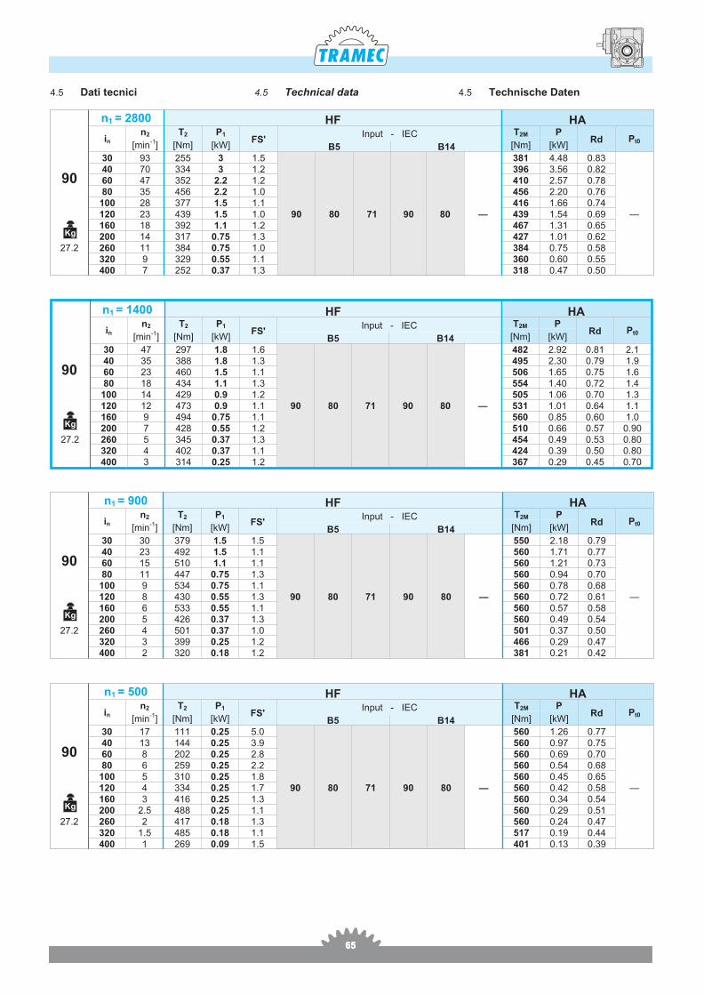
4.5 Technical data 4.5 Technische Daten4.5 Dati tecnici
Kg
Kg
Kg
Kg
656565
90
n1 = 2800 HF HA
inn2 T2 P1
FS'Input - IEC T2M P
Rd Pt0[min-1] [Nm] [kW] [Nm] [kW]B5 B14
30 93 255 3 1.5
90 80 71 90 80 —
381 4.48 0.83
—
40 70 334 3 1.2 396 3.56 0.8260 47 352 2.2 1.2 410 2.57 0.7880 35 456 2.2 1.0 456 2.20 0.76
100 28 377 1.5 1.1 416 1.66 0.74120 23 439 1.5 1.0 439 1.54 0.69160 18 392 1.1 1.2 467 1.31 0.65200 14 317 0.75 1.3 427 1.01 0.62
27.2 260 11 384 0.75 1.0 384 0.75 0.58320 9 329 0.55 1.1 360 0.60 0.55400 7 252 0.37 1.3 318 0.47 0.50
90
n1 = 900 HF HA
inn2 T2 P1
FS'Input - IEC T2M P
Rd Pt0[min-1] [Nm] [kW] [Nm] [kW]B5 B14
30 30 379 1.5 1.5
90 80 71 90 80 —
550 2.18 0.79
—
40 23 492 1.5 1.1 560 1.71 0.7760 15 510 1.1 1.1 560 1.21 0.7380 11 447 0.75 1.3 560 0.94 0.70
100 9 534 0.75 1.1 560 0.78 0.68120 8 430 0.55 1.3 560 0.72 0.61160 6 533 0.55 1.1 560 0.57 0.58200 5 426 0.37 1.3 560 0.49 0.54
27.2 260 4 501 0.37 1.0 501 0.37 0.50320 3 399 0.25 1.2 466 0.29 0.47400 2 320 0.18 1.2 381 0.21 0.42
90
n1 = 1400 HF HA
inn2 T2 P1
FS'Input - IEC T2M P
Rd Pt0[min-1] [Nm] [kW] [Nm] [kW]B5 B14
30 47 297 1.8 1.6
90 80 71 90 80 —
482 2.92 0.81 2.140 35 388 1.8 1.3 495 2.30 0.79 1.960 23 460 1.5 1.1 506 1.65 0.75 1.680 18 434 1.1 1.3 554 1.40 0.72 1.4
100 14 429 0.9 1.2 505 1.06 0.70 1.3120 12 473 0.9 1.1 531 1.01 0.64 1.1160 9 494 0.75 1.1 560 0.85 0.60 1.0200 7 428 0.55 1.2 510 0.66 0.57 0.90
27.2 260 5 345 0.37 1.3 454 0.49 0.53 0.80320 4 402 0.37 1.1 424 0.39 0.50 0.80400 3 314 0.25 1.2 367 0.29 0.45 0.70
90
n1 = 500 HF HA
inn2 T2 P1
FS'Input - IEC T2M P
Rd Pt0[min-1] [Nm] [kW] [Nm] [kW]B5 B14
30 17 111 0.25 5.0
90 80 71 90 80 —
560 1.26 0.77
—
40 13 144 0.25 3.9 560 0.97 0.7560 8 202 0.25 2.8 560 0.69 0.7080 6 259 0.25 2.2 560 0.54 0.68
100 5 310 0.25 1.8 560 0.45 0.65120 4 334 0.25 1.7 560 0.42 0.58160 3 416 0.25 1.3 560 0.34 0.54200 2.5 488 0.25 1.1 560 0.29 0.51
27.2 260 2 417 0.18 1.3 560 0.24 0.47320 1.5 485 0.18 1.1 517 0.19 0.44400 1 269 0.09 1.5 401 0.13 0.39
4.5 Technical data 4.5 Technische Daten4.5 Dati tecnici
Kg
Kg
Kg
Kg
666666
110
n1 = 900 HF HA
inn2 T2 P1
FS'Input - IEC T2M P
Rd Pt0[min-1] [Nm] [kW] [Nm] [kW]B5 B14
30 30 766 3 1.2
112100
90 80112100
90 —
922 3.61 0.80
—
40 23 732 2.2 1.3 937 2.82 0.7860 15 849 1.8 1.1 970 2.06 0.7480 11 912 1.5 1.1 970 1.59 0.72
100 9 811 1.1 1.2 970 1.32 0.69120 8 884 1.1 1.1 970 1.21 0.63160 6 758 0.75 1.3 970 0.96 0.60200 5 902 0.75 1.1 970 0.81 0.57
48.8 260 4 779 0.55 1.1 846 0.60 0.52320 3 616 0.37 1.3 794 0.48 0.49400 2 700 0.37 1.0 700 0.37 0.45
110
n1 = 2800 HF HA
inn2 T2 P1
FS'Input - IEC T2M P
Rd Pt0[min-1] [Nm] [kW] [Nm] [kW]B5 B14
30 93 641 7.5 1.0
112100
90 80112100
90 —
641 7.50 0.84
—
40 70 619 5.5 1.1 658 5.85 0.8260 47 649 4 1.1 698 4.30 0.7980 35 632 3 1.2 782 3.71 0.77
100 28 566 2.2 1.3 727 2.83 0.75120 23 634 2.2 1.2 754 2.61 0.70160 18 807 2.2 1.0 807 2.20 0.67200 14 661 1.5 1.1 749 1.70 0.65
48.8 260 11 589 1.1 1.1 646 1.21 0.60320 9 469 0.75 1.3 611 0.98 0.57400 7 545 0.75 1.0 545 0.75 0.53
110
n1 = 1400 HF HA
inn2 T2 P1
FS'Input - IEC T2M P
Rd Pt0[min-1] [Nm] [kW] [Nm] [kW]B5 B14
30 47 668 4 1.2
112100
90 80112100
90 —
807 4.83 0.82 3.240 35 655 3 1.3 825 3.78 0.80 2.960 23 689 2.2 1.3 864 2.76 0.76 2.480 18 887 2.2 1.1 957 2.37 0.74 2.2
100 14 884 1.8 1.0 884 1.80 0.72 2.1120 12 809 1.5 1.1 916 1.70 0.66 1.7160 9 749 1.1 1.3 970 1.42 0.62 1.5200 7 896 1.1 1.0 896 1.10 0.60 1.5
48.8 260 5 743 0.75 1.0 743 0.75 0.55 1.3320 4 624 0.55 1.2 722 0.64 0.52 1.2400 3 705 0.55 0.9 644 0.48 0.47 1.1
110
n1 = 500 HF HA
inn2 T2 P1
FS'Input - IEC T2M P
Rd Pt0[min-1] [Nm] [kW] [Nm] [kW]B5 B14
30 17 336 0.75 2.9
112100
90 80112100
90 —
970 2.16 0.78
—
40 13 437 0.75 2.2 970 1.67 0.7660 8 616 0.75 1.6 970 1.18 0.7280 6 792 0.75 1.2 970 0.92 0.69
100 5 970 0.75 1.0 970 0.75 0.67120 4 754 0.55 1.3 970 0.71 0.60160 3 933 0.55 1.1 970 0.57 0.56200 2.5 754 0.37 1.3 970 0.48 0.53
48.8 260 2 900 0.37 1.1 955 0.39 0.49320 1.5 700 0.25 1.3 889 0.32 0.46400 1 568 0.18 1.3 727 0.23 0.41
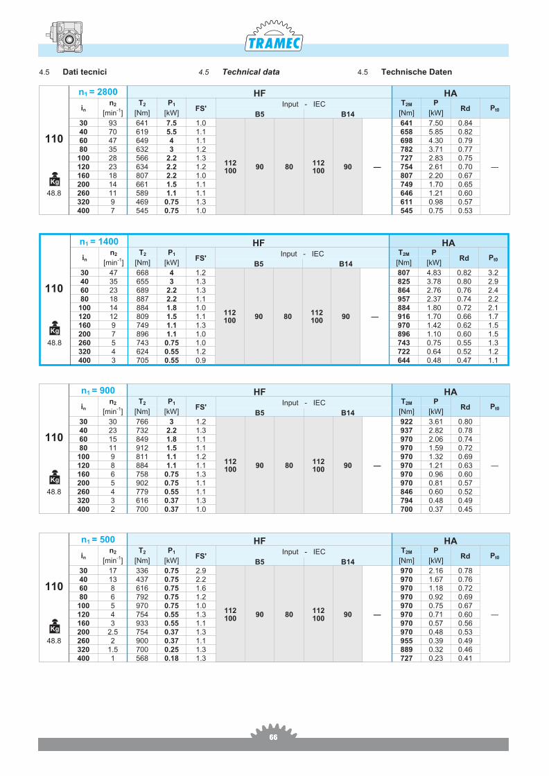
4.5 Technical data 4.5 Technische Daten4.5 Dati tecnici
Kg
Kg
Kg
Kg
676767
H40
in HA HF
B5 - B14IEC 56 IEC 63
30 0.080 0.125 0.12540 0.079 0.123 0.12460 0.077 0.122 0.12380 0.076 0.120 0.121
100 0.075 0.120 0.120120 0.077 0.121 0.122160 0.075 0.120 0.120200 0.075 0.120 0.120260 0.074 0.119 0.119320 0.074 0.119 0.119400 0.074 0.119 0.119
H50
in HA HF
B5 B5 - B14IEC 56 IEC 63 IEC 71
30 0.161 0.208 0.366 0.38340 0.156 0.203 0.361 0.37760 0.152 0.199 0.357 0.37480 0.148 0.194 0.352 0.369
100 0.147 0.194 0.352 0.368120 0.150 0.197 0.355 0.372160 0.146 0.193 0.351 0.368200 0.141 0.188 0.346 0.363260 0.138 0.185 0.343 0.360320 0.138 0.185 0.343 0.360400 0.138 0.185 0.343 0.360
H63
in HA HF
B5 B5 - B14IEC 63 IEC 71 IEC 80
30 0.405 0.639 0.656 1.21940 0.392 0.626 0.643 1.20660 0.383 0.617 0.634 1.19780 0.364 0.598 0.615 1.178
100 0.362 0.596 0.613 1.176120 0.377 0.612 0.628 1.191160 0.361 0.595 0.612 1.175200 0.360 0.595 0.611 1.175260 0.354 0.588 0.605 1.168320 0.354 0.588 0.605 1.168400 0.354 0.588 0.605 1.168
H75
in HA HF
B5 B5 - B14IEC 71 IEC 80 IEC 90
30 0.865 1.643 1.778 2.85540 0.835 1.613 1.748 2.82560 0.813 1.592 1.726 2.80480 0.777 1.556 1.690 2.768
100 0.773 1.551 1.686 2.764120 0.801 1.579 1.714 2.791160 0.770 1.548 1.683 2.760200 0.769 1.547 1.682 2.759260 0.751 1.530 1.664 2.742320 0.751 1.530 1.664 2.742400 0.751 1.529 1.664 2.742
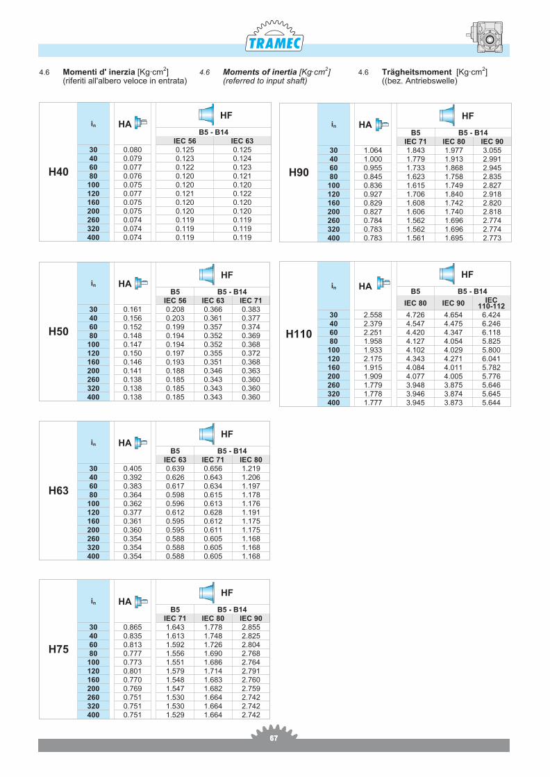
4.6 Momenti d' inerzia [Kg.cm2](riferiti all'albero veloce in entrata)
4.6 Moments of inertia [Kg.cm2](referred to input shaft)
4.6 Trägheitsmoment [Kg.cm2]((bez. Antriebswelle)
H90
in HA HF
B5 B5 - B14IEC 71 IEC 80 IEC 90
30 1.064 1.843 1.977 3.05540 1.000 1.779 1.913 2.99160 0.955 1.733 1.868 2.94580 0.845 1.623 1.758 2.835
100 0.836 1.615 1.749 2.827120 0.927 1.706 1.840 2.918160 0.829 1.608 1.742 2.820200 0.827 1.606 1.740 2.818260 0.784 1.562 1.696 2.774320 0.783 1.562 1.696 2.774400 0.783 1.561 1.695 2.773
H110
in HA
HF
B5 B5 - B14
IEC 80 IEC 90 IEC110-112
30 2.558 4.726 4.654 6.42440 2.379 4.547 4.475 6.24660 2.251 4.420 4.347 6.11880 1.958 4.127 4.054 5.825
100 1.933 4.102 4.029 5.800120 2.175 4.343 4.271 6.041160 1.915 4.084 4.011 5.782200 1.909 4.077 4.005 5.776260 1.779 3.948 3.875 5.646320 1.778 3.946 3.874 5.645400 1.777 3.945 3.873 5.644
686868
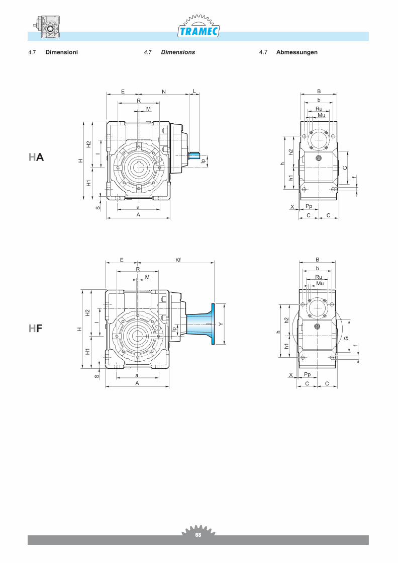
4.7 Dimensions 4.7 Abmessungen4.7 Dimensioni
HA
HF
E
R
N
M
a
L
H Ip
I
H1
H2
A
S X
C
Pp
f
G
MuRu
b
B
h1
h2
h
C
E
R
Kf
M
a
H Ip
I
H1
H2
A
S X
C
Pp
f
G
MuRu
b
B
h1
h2
h
Y
C
696969
4.7 Dimensions 4.7 Abmessungen4.7 Dimensioni
90°
90
°
90
°
45° 45°
45°45°
40 - 50 63 - 75 - 90 - 110
4 Fori / Holes / Bohrungen 8 Fori / Holes / Bohrungen
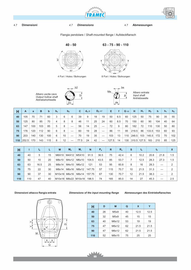
Flan gia pen do la re / Shaft-mo un ted flan ge / Auf steckflansch
H I Ip L M Me Mu N Pp R Ru S te t2 X
40 40 5 15 M6X10 M4X12 M5X10 91.5 36.5 75 42.4 6 10.2 20.8 21.8 1.5
50 50 10 20 M8x10 M4x12 M6x10 104.5 43.5 85 53.7 7 12.5 28.3 27.3 1.5
63 63 16.5 25 M8x14 M4x10 M6x12 121 53 95 60.8 8 16 28.3 — 2
75 75 22 30 M8x14 M6x16 M8x12 147.75 57 115 70.7 10 21.5 31.3 — 2
90 90 37 30 M10x18 M6x16 M8x14 157.75 67 130 70.7 12 21.5 38.3 — 2
110 110 47 40 M10x18 M8x22 M10x18 196.5 74 165 85.0 14 27 45.3 — 2.5
H A a B b be b2 C de j6 D2 H7 E f G h8 H H1 H2 h h1 h2
40 105 70 71 60 3 6 6 39 9 18 19 50 6.5 60 125 50 75 90 35 55
50 125 80 85 70 4 8 8 46 11 25 24 60 8.5 70 150 60 90 104 40 64
63 147 100 103 85 5 8 — 56 14 25 — 72 9 80 182 72 110 130 50 80
75 176 120 112 90 6 8 — 60 19 28 — 86 11 95 219.5 86 133.5 153 60 93
90 203 140 130 100 6 10 — 70 19 35 — 103 13 110 248.5 103 145.5 172 70 102
110 252.5 170 143 115 8 12 — 77.5 24 42 — 127.5 14 130 310.5 127.5 183 210 85 125
Albero uscita cavoOutput hollow shaftAbtriebshohlwelle
Albero entrataInput shaftAntriebswelle
D2 de
Me
t2 te
b2 be
Dimensioni attacco flangia entrata Dimensions of the input mounting flange Abmessungen des Eintriebsflansches
X
M
X
D
Y
Q
Y
H D M Q X Y
40 26 M5x9 40 12.5 12.5
50 32 M5x9 45 15 15
63 40 M6x12 53 19 19
75 47 M6x12 62 21.5 21.5
90 47 M6x12 62 21.5 21.5
110 52 M8x15 75 25 25
707070
F..S F..2F..DStandard
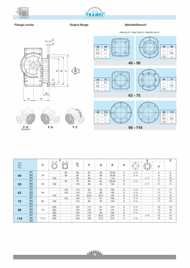
TipoTypeTyp
C
FG H8 P Q R U
V Z
Ø
40F1
39
85 60 67 28 75-90 4 n* 4 9 8F2 85 60 97 58 75-90 4 n* 4 9 8F3 140 95 80 41 115 5 n* 7 9 10
50F1
46
94 70 90 44 85-95 5 n* 4 11 10F2 160 110 89 43 130 5 n* 7 11 11F3
63F1
56
142 115 82 26 150 5 n* 4 11 11F2 142 115 112 56 150 5 n* 4 11 11F3 160 110 80.5 24.5 130 5 n* 4 11 12
75F1
60
160 130 111 51 165 5 n* 4 13 12F2 160 110 90 30 130 6 n* 4 11 13F3
90F1
70
200 152 111 41 175 5 n* 4 13 12F2 200 152 151 81 175 5 n* 4 13 13F3 200 130 110 40 165 6 n* 4 11 11
110F1
77.5
260 170 131 53.5 230 6 n* 8 13 15F2 250 180 150 72.5 215 5 n* 4 15 16F3
Flan gia uscita Output flange Abtriebsflansch
G R
V
U
Z
F
C
Q
P
90 - 110
63 - 75
40 - 50
90 110
F1 —
F2 F2
F3 —
63 75
— —
— F2
F3 —
40 50
— —
— F2
F3 —
90 110
— F1
— —
— —
63 75
F1 F1
F2 —
— —
40 50
F1 F1
F2 —
— —
A
Vista da A / View from A / Ansicht von A
717171
Z1
U1
KF
YR1
G1
V1
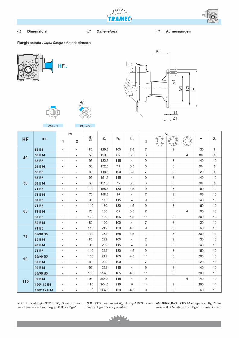
Flan gia en tra ta / Input flan ge / Antrieb sflansch
HF IEC
PMG1H7
KF R1 U1
V1
Y Z11 2 ∅
40
56 B5 • • 80 129.5 100 3.5 7 8 120 8
56 B14 • 50 129.5 65 3.5 6 4 80 8
63 B5 • • 95 132.5 115 4 9 8 140 10
63 B14 • • 60 132.5 75 3.5 6 8 90 8
50
56 B5 • • 80 148.5 100 3.5 7 8 120 8
63 B5 • • 95 151.5 115 4 9 8 140 10
63 B14 • • 60 151.5 75 3.5 6 8 90 8
71 B5 • • 110 158.5 130 4.5 9 8 160 10
71 B14 • • 70 158.5 85 4 7 8 105 10
63
63 B5 • • 95 173 115 4 9 8 140 10
71 B5 • • 110 180 130 4.5 9 8 160 10
71 B14 • 70 180 85 3.5 7 4 105 10
80 B5 • • 130 190 165 4.5 11 8 200 10
80 B14 • • 80 190 100 4 7 8 120 10
75
71 B5 • • 110 212 130 4.5 9 8 160 10
80/90 B5 • • 130 232 165 4.5 11 8 200 10
80 B14 • • 80 222 100 4 7 8 120 10
90 B14 • • 95 232 115 4 9 8 140 10
90
71 B5 • • 110 222 130 4.5 9 8 160 10
80/90 B5 •· • 130 242 165 4.5 11 8 200 10
80 B14 • • 80 232 100 4 7 8 120 10
90 B14 • • 95 242 115 4 9 8 140 10
110
80/90 B5 • • 130 294.5 165 4.5 11 8 200 10
90 B14 • 95 294.5 115 4 9 4 140 10
100/112 B5 • • 180 304.5 215 5 14 8 250 14
100/112 B14 • • 110 304.5 130 4.5 9 8 160 10
4.7 Dimensions 4.7 Abmessungen4.7 Dimensioni
N.B.: Il mon tag gio STD di PM=2 solo quan donon è pos si bi le il mon tag gio STD di PM=1.
PM = 1 PM = 2
45°
N.B.: STD mo un ting of PM=2 only if STD mo un -ting of PM=1 is not pos si ble.
ANMERKUNG: STD Mon ta ge von PM=2 nurwenn STD Mon ta ge von PM=1 un mö glich ist.
H ..F
727272
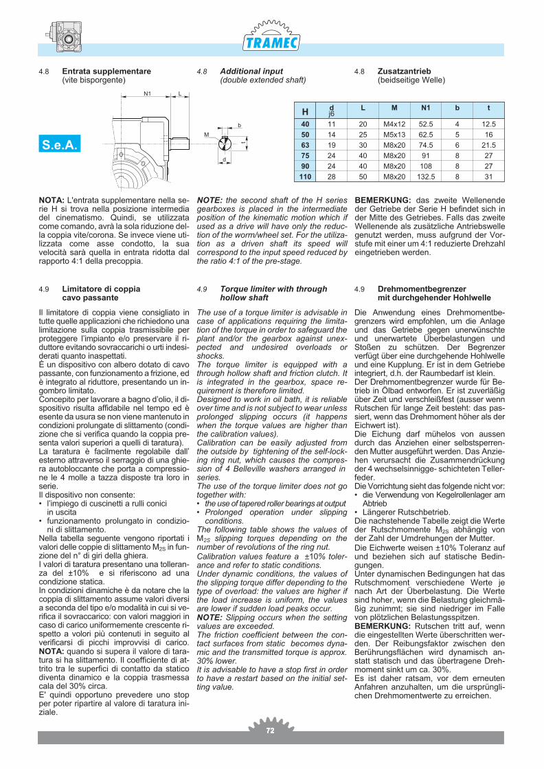
4.8 Additional input(double extended shaft)
4.8 Zusatzantrieb(beidseitige Welle)
4.8 Entrata supplementare(vite bisporgente)
Hdj6
L M N1 b t
40 11 20 M4x12 52.5 4 12.5
50 14 25 M5x13 62.5 5 16
63 19 30 M8x20 74.5 6 21.5
75 24 40 M8x20 91 8 27
90 24 40 M8x20 108 8 27
110 28 50 M8x20 132.5 8 31
N1 L
d
M
t
b
NOTA: L'en tra ta sup ple men ta re nel la se -rie H si tro va nel la po si zio ne in ter me diadel ci ne ma ti smo. Quin di, se uti liz za tacome co man do, avrà la sola ri du zio ne del -la cop pia vite/co ro na. Se in ve ce vie ne uti -liz za ta come asse con dot to, la suave lo ci tà sarà quel la in en tra ta ri dot ta dalrap por to 4:1 del la pre cop pia.
The use of a torque lim iter is ad vis able incase of ap pli ca tions re quir ing the lim i ta -tion of the torque in or der to safe guard theplant and/or the gear box against un ex -pected and un de sired over loads orshocks. The torque lim iter is equipped with athrough hol low shaft and fric tion clutch. Itis in te grated in the gear box, space re -quire ment is there fore lim ited.De signed to work in oil bath, it is re li ableover time and is not sub ject to wear un less pro longed slip ping oc curs (it hap penswhen the torque val ues are higher thanthe cal i bra tion val ues). Cal i bra tion can be eas ily ad justed fromthe out side by tight en ing of the self-lock -ing ring nut, which causes the com pres -sion of 4 Belleville wash ers ar ranged in se ries.The use of the torque lim iter does not goto gether with:• the use of ta pered roller bear ings at out put• Pro longed op er a tion un der slip ping
con di tions.The fol low ing ta ble shows the val ues ofM2S slip ping torques de pend ing on thenum ber of rev o lu tions of the ring nut. Cal i bra tion val ues fea ture a ±10% tol er -ance and re fer to static con di tions.Un der dy namic con di tions, the val ues ofthe slip ping torque dif fer de pend ing to thetype of over load: the val ues are higher ifthe load in crease is uni form, the val uesare lower if sud den load peaks oc cur. NOTE: Slip ping oc curs when the set tingval ues are ex ceeded. The fric tion co ef fi cient bet we en the con -tact sur fa ces from sta tic be co mes dyna -mic and the tran smit ted tor que is ap prox.30% lo wer. It is ad vi sa ble to have a stop first in or derto have a re start ba sed on the ini tial set -ting va lue.
Die Anwen dung ei nes Dreh mo men tbe -gren zers wird em pfoh len, um die Anla geund das Ge trie be ge gen unerwünschteund uner war te te Über be la stun gen undSto ßen zu schüt zen. Der Be gren zerverfügt über eine durchge hen de Hoh lwel leund eine Kup plung. Er ist in dem Ge trie bein te griert, d.h. der Ra um be darf ist kle in.Der Dreh mo ment be gren zer wur de für Be -trieb in Öl bad ent wor fen. Er ist zu ver lä ßigüber Zeit und ver schleiß fest (aus ser wennRut schen für lan ge Zeit be steht: das pas -siert, wenn das Dreh mo ment hö her als derEich wert ist). Die Ei chung darf mü he los von aus sendurch das An zie hen ei ner selbst sper ren -den Mut ter aus ge führt wer den. Das An zie -hen ver ur sacht die Zu sam men drü ckungder 4 wech sel sin nig ge- schich te ten Tel ler -fe der. Die Vor ric htung sieht das fol gen de nicht vor:• die Ver wen dung von Ke gel rol len la ger am
Abtrieb• Län ge rer Rutsch be trieb.Die nach ste hen de Ta bel le zeigt die Wer teder Rut schmo men te M2S ab hän gig vonder Zahl der Um dre hun gen der Mut ter. Die Eich wer te wei sen ±10% To le ranz aufund be zie hen sich auf sta ti sche Be din -gun gen.Un ter dy na mi schen Be din gun gen hat dasRut schmo ment ver schie de ne Wer te jenach Art der Über be la stung. Die Wer tesind ho her, wenn die Be la stung gleich mä -ßig zu nimmt; sie sind nied ri ger im Fal levon plötz li chen Be la stungs spit zen.BEMERKUNG: Rut schen tritt auf, wenndie ein ge stel lten Wer te überschrit ten wer -den. Der Re i bungsfak tor zwi schen denBerührungsflächen wird dyna misch an -statt sta tisch und das über tra ge ne Dreh -mo ment sinkt um ca. 30%. Es ist da her rat sam, vor dem er ne u tenAnfah ren an zu hal ten, um die ursprüngli -chen Dreh mo men twer te zu er re i chen.
Il li mi ta to re di cop pia vie ne con si glia to intut te quel le ap pli ca zio ni che ri chie do no una li mi ta zio ne sul la cop pia tra smis si bi le perpro teg ge re l’im pian to e/o pre ser va re il ri -dut to re evi tan do so vrac ca ri chi o urti in de si -de ra ti quan to ina spet ta ti.È un di spo si ti vo con al be ro do ta to di cavopas san te, con fun zio na men to a fri zio ne, ed è in te gra to al ri dut to re, pre sen tan do un in -gom bro li mi ta to.Con ce pi to per la vo ra re a ba gno d’o lio, il di -spo si ti vo ri sul ta af fi da bi le nel tem po ed èesen te da usu ra se non vie ne man te nu to in con di zio ni pro lun ga te di slit ta men to (con di -zio ne che si ve ri fi ca quan do la cop pia pre -sen ta va lo ri su pe rio ri a quel li di ta ra tu ra).La ta ra tu ra è fa cil men te re go la bi le dall’ester no at tra ver so il ser rag gio di una ghie -ra au to bloc can te che por ta a com pres sio -ne le 4 mol le a taz za di spo ste tra loro inse rie.Il di spo si ti vo non con sen te:• l’im pie go di cu sci net ti a rul li co ni ci
in usci ta• fun zio na men to pro lun ga to in con di zio -
ni di slit ta men to.Nel la ta bel la se guen te ven go no ri por ta ti iva lo ri del le cop pie di slit ta men to M2S in fun -zio ne del n° di giri del la ghie ra.I va lo ri di ta ra tu ra pre sen ta no una tol le ran -za del ±10% e si ri fe ri sco no ad unacon di zio ne sta ti ca.In con di zio ni di na mi che è da no ta re che lacop pia di slit ta men to as su me va lo ri di ver sia se con da del tipo e/o mo da li tà in cui si ve -ri fi ca il so vrac ca ri co: con va lo ri mag gio ri incaso di ca ri co uni for me men te cre scen te ri -spet to a vo lo ri più con te nu ti in se gui to alve ri fi car si di pic chi im prov vi si di ca ri co.NOTA: quan do si su pe ra il va lo re di ta ra -tu ra si ha slit ta men to. Il co ef fi cien te di at -tri to tra le su per fi ci di con tat to da sta ti codi ven ta di na mi co e la cop pia tra smes sacala del 30% cir ca.E' quin di op por tu no pre ve de re uno stopper po ter ri par ti re al va lo re di ta ra tu ra ini -zia le.
NOTE: the sec ond shaft of the H se riesgear boxes is placed in the in ter me di atepo si tion of the ki ne matic mo tion which ifused as a drive will have only the re duc -tion of the worm/wheel set. For the uti li za -tion as a driven shaft its speed willcor re spond to the in put speed re duced bythe ra tio 4:1 of the pre-stage.
BEMERKUNG: das zwei te Wel len en deder Ge trie be der Se rie H be fin det sich inder Mit te des Ge trie bes. Falls das zwei teWel len en de als zu sätz li che An triebs wel lege nutzt wer den, muss auf grund der Vor -stu fe mit ei ner um 4:1 re du zier te Drehzahleingetrieben werden.
4.9 Limitatore di coppiacavo passante
4.9 Torque limiter with throughhollow shaft
4.9 Drehmomentbegrenzer mit durchgehender Hohlwelle
S.e.A.
737373
( ) A richiesta / On request / Auf Anfrage
CtCt
CLCL
MM
GG
DD
CC
LD LS
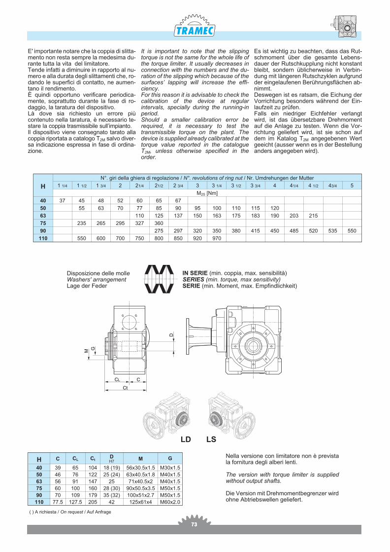
Di spo si zio ne del le molleWa shers' ar ran ge mentLage der Fe der
IN SERIE (min. cop pia, max. sen si bi li tà)SERIES (min. tor que, max sen si ti vity)SERIE (min. Mo ment, max. Empfin dlic hke it)
E' im por tan te no ta re che la cop pia di slit ta -men to non re sta sem pre la me de si ma du -ran te tut ta la vita del li mi ta to re.Ten de in fat ti a di mi nu i re in rap por to al nu -me ro e alla du ra ta de gli slit ta men ti che, ro -dan do le su per fi ci di con tat to, ne au men-tano il ren di men to.È quin di op por tu no ve ri fi ca re pe rio di ca -men te, so prat tut to du ran te la fase di ro -dag gio, la ta ra tu ra del di spo si ti vo.Là dove sia ri chie sto un er ro re piùcon te nuto nel la ta ra tu ra, è ne ces sa rio te -sta re la cop pia tra smis si bi le sul l’im pian to.Il di spo si ti vo vie ne con se gna to ta ra to allacop pia ri por ta ta a ca ta lo go T2M sal vo di ver -sa in di ca zio ne espres sa in fase di or di na -zio ne.
It is im por tant to note that the slip pingtorque is not the same for the whole life ofthe torque lim iter. It usu ally de creases incon nec tion with the num bers and the du -ra tion of the slip ping which be cause of thesur faces’ lap ping will in crease the ef fi -ciency.For this rea son it is ad vis able to check thecal i bra tion of the de vice at reg u larin ter vals, spe cially dur ing the run ning-inpe riod. Should a smaller cal i bra tion er ror bere quired, it is nec es sary to test thetrans mis si ble torque on the plant. Thede vice is sup plied al ready cal i brated at the torque value re ported in the cat a logueT2M, un less oth er wise spec i fied in theor der.
Es ist wich tig zu be ach ten, dass das Rut -schmo ment über die ge sam te Le bens -dau er der Rutsch kupp lung nicht kon stantbleibt, son dern üb li cher wei se in Ver bin -dung mit län ge ren Rutsch zyk len auf grundder ein ge lau fe nen Be rüh rungsflä chen ab -nimmt.Des we gen ist es rat sam, die Ei chung derVor rich tung be son ders wäh rend der Ein -lauf zeit zu prü fen.Falls ein nied ri ger Eich feh ler ver langtwird, ist das über setz ba re Dreh mo mentauf die An la ge zu tes ten. Wenn die Vor -rich tung ge lie fert wird, ist sie schon aufdem im Ka ta log T2M an ge ge be nen Wertge eicht (aus ser wenn es in der Be stel lungan ders an ge ge ben wird).
H C CL CtDH7
M G
40 39 65 104 18 (19) 56x30.5x1.5 M30x1.5
50 46 76 122 25 (24) 63x40.5x1.8 M40x1.5
63 56 91 147 25 71x40.5x2 M40x1.5
75 60 100 160 28 (30) 90x50.5x3.5 M50x1.5
90 70 109 179 35 (32) 100x51x2.7 M50x1.5
110 77.5 127.5 205 42 125x61x4 M60x2.0
Nel la ver sio ne con li mi ta to re non è pre vi stala for ni tu ra de gli al be ri len ti.
The ver sion with tor que li mi ter is sup pliedwit ho ut out put shafts.
Die Ver sion mit Dreh mo men tbe gren zer wird ohne Abtrieb swel len ge lie fert.
H
N°. giri della ghiera di regolazione / N°. revolutions of ring nut / Nr. Umdrehungen der Mutter
1 1/4 1 1/2 1 3/4 2 21/4 21/2 2 3/4 3 3 1/4 3 1/2 3 3/4 4 41/4 4 1/2 43/4 5
M2S [Nm]
40 37 45 48 52 60 65 67
50 55 63 70 77 85 90 95 100 110 115 120
63 110 125 137 150 163 175 183 190 203 215
75 235 265 295 327 360
90 275 297 320 350 380 415 450 485 520 535 550
110 550 600 700 750 800 850 920 970
747474
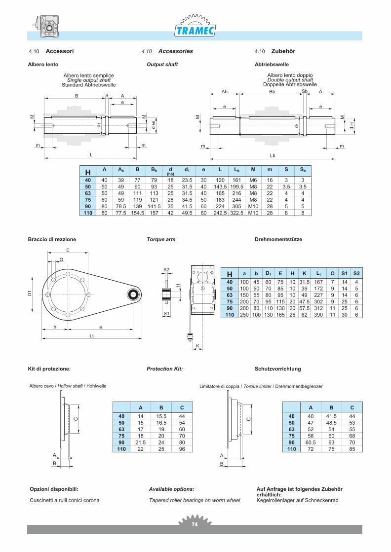
4.10 Accessories 4.10 Zubehör4.10 Accessori
Albe ro len to dop pioDo u ble out put shaft
Dop pel te Abtrieb swel le
L
mMM
d h
6
e
ASB
m
d1
Lb
m
Ab
m
M M
d h
6
ABb
ee
Sb
d1
H
S2
O
E
S1
K
D1
b a
Lt
Albe ro len to sem pli ceSin gle out put shaft
Stan dard Abtrieb swel le
HA Ab B Bb d
(h6)d1 e L Lb M m S Sb
40 40 39 77 79 18 23.5 30 120 161 M6 16 3 350 50 49 90 93 25 31.5 40 143.5 199.5 M8 22 3.5 3.563 50 49 111 113 25 31.5 40 165 216 M8 22 4 475 60 59 119 121 28 34.5 50 183 244 M8 22 4 490 80 78.5 139 141.5 35 41.5 60 224 305 M10 28 5 5
110 80 77.5 154.5 157 42 49.5 60 242.5 322.5 M10 28 8 8
H a b D1 E H K Lt O S1 S2
40 100 45 60 75 10 31.5 167 7 14 450 100 50 70 85 10 39 172 9 14 563 150 55 80 95 10 49 227 9 14 675 200 70 95 115 20 47.5 302 9 25 690 200 80 110 130 20 57.5 312 11 25 6
110 250 100 130 165 25 62 390 11 30 6
Ava i la ble op tions:
Ta pe red rol ler be a rings on worm whe el
Auf Anfra ge ist fol gen des Zu be hörerhältlich:Ke gel rol len la ger auf Schnec ken rad
Opzio ni di spo ni bi li:
Cu sci net ti a rul li co ni ci co ro na
Albero lento Output shaft Abtriebswelle
Brac cio di re a zio ne Tor que arm Dreh mo mentstütze
Kit di protezione: Protection Kit: Schutzvorrichtung
A
C
B
Albero cavo / Hollow shaft / Hohlwelle
A B C
40 14 15.5 4450 15 16.5 5463 17 19 6075 18 20 7090 21.5 24 80
110 22 25 96A
B
C
Limitatore di coppia / Torque limiter / Drehmomentbegrenzer
A B C
40 40 41.5 4450 47 48.5 5363 52 54 5575 58 60 6890 60.5 63 70
110 72 75 85
757575
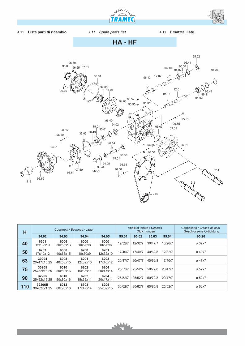
4.11 Spare parts list 4.11 Er satz teil liste4.11 Lista parti di ricambio
HCuscinetti / Bearings / Lager
Anelli di tenuta / Oilseals Öldichtungen
Cappellotto / Closed oil seal Geschlossene Öldichtung
94.02 94.03 94.04 94.05 95.01 95.02 95.03 95.04 95.26
406201
12x32x106006
30x55x136000
10x26x86000
10x26x812/32/7 12/32/7 30/47/7 10/26/7 ø 32x7
506203
17x40x126008
40x68x156200
10x30x96201
12x32x1017/40/7 17/40/7 40/62/8 12/32/7 ø 40x7
6330204
20x47x15.256008
40x68x156201
12x32x106203
17x40x1220/47/7 20/47/7 40/62/8 17/40/7 ø 47x7
7530205
25x52x16.256010
50x80x166202
15x35x116204
20x47x1425/52/7 25/52/7 50/72/8 20/47/7 ø 52x7
9032205
25x52x19.256010
50x80x166202
15x35x116204
20x47x1425/52/7 25/52/7 50/72/8 20/47/7 ø 52x7
11032206B
30x62x21.256012
60x95x186303
17x47x146205
25x52x1530/62/7 30/62/7 60/85/8 25/52/7 ø 62x7
HA - HF
214
215
213
96.61
95.51
94.0296.31
96.41
96.55
09.0195.03
96.13
96.13
12.01
96.55
96.55
96.52
01.01
11.0194.03
33.01
96.60
07.01
96.5095.03
96.55 96.1094.02
96.31
96.41
95.02
95.26
12.02
94.03
96.5094.04
96.55
96.5095.04
96.6407.50
96.62212
96.4494.05
15.01
94.02
96.40
18.0195.01
96.43
96.14
33.0296.55
96.50
04.01


![L’interpretazione dei sogni [Die traumdeutung]](https://static.fdocumenti.com/doc/165x107/62d6129e02ded467141fb7cd/linterpretazione-dei-sogni-die-traumdeutung.jpg)