
MANUALE DI ISTRUZIONI INSTRUCTION MANUAL …...STAGE LIGHT 300 HTI 300W/DX HTI 300W/DEL ® 1 AGE...
19
STAGE LIGHT 300 HTI 300W/DX HTI 300W/DEL ® 1 STAGE LIGHT 300 I GB D E F Complimenti per aver scelto un prodotto Clay Paky! La ringraziamo per la preferenza e La informiamo che anche questo prodotto, come tutti gli altri della ricca gamma Clay Paky, è stato progettato e realizzato nel segno della qualità, per garantirLe sempre l’eccellenza delle prestazioni e rispondere meglio alle Sue aspettative ed esigenze. Leggere attentamente in tutte le sue parti il presente manuale d’istruzioni e conservarlo accuratamente per riferimenti futuri. La conoscenza delle informazioni ed il rispetto delle prescrizioni contenute in questa pubblicazione sono essenziali per garantire la correttezza e la sicurezza delle operazioni di installazione, uso e manutenzione dell’apparecchio. CLAY PAKY S.p.A. declina ogni responsabilità per danni all’apparecchio o ad altre cose o persone, derivanti da installazione, uso e manutenzione effettuate non in conformità con quanto riportato sul presente manuale di istruzioni, che deve sempre accompagnare l’apparecchio. CLAY PAKY S.p.A. si riserva la facoltà di modificare, in qualunque momento e senza preavviso, le caratteristiche menzionate nel presente manuale di istruzioni. Congratulations on choosing a Clay Paky product! We thank you for your custom. Please note that this product, as all the others in the rich Clay Paky range, has been designed and made with total quality to ensure excellent performance and best meet your expectations and requirements. Carefully read this instruction manual in its entirety and keep it safe for future reference. It is essential to know the information and comply with the instructions given in this manual to ensure the fitting is installed, used and serviced correctly and safely. CLAY PAKY S.p.A. disclaims all liability for damage to the fitting or to other property or persons deriving from installation, use and maintenance that have not been carried out in conformity with this instruction manual, which must always accompany the fitting. CLAY PAKY S.p.A. reserves the right to modify the characteristics stated in this instruction manual at any time and without prior notice. Félicitations, vous venez de choisir un produit Clay Paky! Nous vous remercions de votre préférence et vous informons que comme tous les autres produits de la vaste gamme Clay Paky, ce produit a lui aussi été conçu et réalisé sous le signe de la qualité, afin de vous garantir en toutes occasions l'excellence des performances, et d'apporter une réponse plus précise à vos attentes et exigences. Lire attentivement et entièrement le présent manuel d'instructions, et le conserver soigneusement pour toutes références futures. La connaissance des informations et le respect des prescriptions contenues dans la présente publication sont essentiels afin de garantir la correction et la sécurité des opérations d'installation, d'utilisation et d'entretien de l'appareil. CLAY PAKY S.p.A. décline toute responsabilité en cas de dommages causés à l'appareil, à des personnes ou à des choses par une installation, une utilisation ou un entretien n'ayant pas été réalisés conformément aux indications fournies dans le présent manuel d'instructions, qui doit toujours accompagner l'appareil. CLAY PAKY S.p.A. se réserve la faculté de modifier, à tout moment et sans préavis, les caractéristiques mentionnées dans le présent manuel d'instructions. Kompliment für Ihre Wahl eines Produkts von Clay Paky! Wir danken Ihnen für das entgegengebrachte Vertrauen und möchten Sie daran erinnern, dass bei der Herstellung auch dieses Produkts - wie bei allen Produkten des großen Sortiments von Clay Paky - auf erste Qualität Wert gelegt wurde, um Ihnen immer hervorragende Leistungen garantieren, und Ihre Erwartungen und Anforderungen stets bestens erfüllen zu können. Lesen Sie diese Bedienungsanleitung bitte vollständig durch und bewahren Sie sie für späteres Nachschlagen sorgfältig auf. Die Kenntnis der darin enthaltenen Informationen und die strikte Befolgung der Anweisungen ist die Voraussetzung für eine korrekte und sichere Installation, Benutzung und Wartung des Geräts. Die Firma CLAY PAKY S.p.A. lehnt jede Haftung für Schäden an dem Gerät bzw. sonstige Sach- und Personenschäden ab, die durch eine nicht mit den Anweisungen dieser Bedienungsanleitung konforme Installation, Benutzung und Wartung verursacht werden. Die Bedienungsanleitung muss immer bei dem Gerät bleiben. Die Firma CLAY PAKY S.p.A. behält sich das Recht vor, die in der vorliegenden Bedienungsanleitung enthaltenen Daten jederzeit und ohne vorherige Benachrichtigung zu ändern. Enhorabuena por haber elegido un artículo Clay Paky y gracias por honrarnos con su preferencia. Este producto, como todos los demás de esta marca, ha sido proyectado y realizado con los más elevados criterios de calidad para garantizarle siempre unas prestaciones excelentes y satisfacer mejor sus expectativas y exigencias. Lea atentamente todo el manual de instrucciones y guárdelo para futuras consultas. Las informaciones e indicaciones que figuran en esta publicación son esenciales para efectuar de modo correcto y seguro las operaciones de instalación, uso y mantenimiento del aparato. CLAY PAKY S.p.A. declina toda responsabilidad ante daños sufridos por el proyector, por personas u objetos, que puedan atribuirse a operaciones de instalación, uso o mantenimiento no conformes a lo indicado en este manual, el cual debe guardarse siempre junto con el aparato. CLAY PAKY S.p.A. se reserva el derecho de modificar, en cualquier momento y sin aviso previo, las características mencionadas en el presente manual de instrucciones. MANUALE DI ISTRUZIONI INSTRUCTION MANUAL MANUEL D'INSTRUCTIONS BEDIENUNGSANLEITUNG MANUAL DE INSTRUCCIONES I F GB D E INDICE INDEX SOMMAIRE INHALT INDICE I GB D E F 2 4 7 10 14 17 18 20 22 24 Informazioni di sicurezza - Safety information Informations de sécurité - Informationen über Sicherheit - Información de seguridad Installazione e messa in funzione - Installation and start-up Installation et mise en fonction - Installation und Inbetriebnahme - Instalación y puesta en función Funzioni canali ed opzioni - Channel functions and options - Fonctions canaux et options Funktionen der Kanäle und Optionen - Funciones de los canales y opciones Manutenzione - Maintenance - Entretien - Wartung - Mantenimiento Dati Tecnici - Technical data - Données techniques - Technische Daten - Datos técnicos Causa e soluzione dei problemi - Cause and solution of problems - Cause et solution des problèmes Ursachen und Abhilfe bei Betriebsstörungen - Causas y soluciones de problemas Diagrammi fotometrici - Photometric diagrams - Diagrammes photométriques Fotometrische Diagramme - Diagramos fotométricos Schemi elettrici - Wiring diagrams - Schémas électriques Elektrische Schaltpläne - Esquemas eléctricos Ricambi - Spare parts - Pièces de rechange - Ersatzteile - Recambios Page Contenuto - Contents - Contenu - Inhalt - Contenido Disimballo e predisposizione - Unpacking and preparation Déballage et préparation - Auspacken und Vorbereiten - Desembalaje y preparación
Transcript of MANUALE DI ISTRUZIONI INSTRUCTION MANUAL …...STAGE LIGHT 300 HTI 300W/DX HTI 300W/DEL ® 1 AGE...
STAGE LIGHT 300 HTI 300W/DXHTI 300W/DEL
®
1
STAG
E LIG
HT 3
00
I
GB
D
E
F
Complimenti per aver scelto un prodotto Clay Paky! La ringraziamo per la preferenza e La informiamo che anche questo prodotto, come tutti gli altri della ricca gammaClay Paky, è stato progettato e realizzato nel segno della qualità, per garantirLe sempre l’eccellenza delle prestazioni e rispondere meglio alle Sue aspettative ed esigenze.
Leggere attentamente in tutte le sue parti il presente manuale d’istruzioni e conservarlo accuratamente per riferimenti futuri. La conoscenza delle informazioni ed il rispettodelle prescrizioni contenute in questa pubblicazione sono essenziali per garantire la correttezza e la sicurezza delle operazioni di installazione, uso e manutenzionedell’apparecchio.CLAY PAKY S.p.A. declina ogni responsabilità per danni all’apparecchio o ad altre cose o persone, derivanti da installazione, uso e manutenzione effettuate non inconformità con quanto riportato sul presente manuale di istruzioni, che deve sempre accompagnare l’apparecchio. CLAY PAKY S.p.A. si riserva la facoltà di modificare, in qualunque momento e senza preavviso, le caratteristiche menzionate nel presente manuale di istruzioni.
Congratulations on choosing a Clay Paky product! We thank you for your custom. Please note that this product, as all the others in the rich Clay Paky range, has beendesigned and made with total quality to ensure excellent performance and best meet your expectations and requirements.
Carefully read this instruction manual in its entirety and keep it safe for future reference. It is essential to know the information and comply with the instructions given in thismanual to ensure the fitting is installed, used and serviced correctly and safely.CLAY PAKY S.p.A. disclaims all liability for damage to the fitting or to other property or persons deriving from installation, use and maintenance that have not been carriedout in conformity with this instruction manual, which must always accompany the fitting.CLAY PAKY S.p.A. reserves the right to modify the characteristics stated in this instruction manual at any time and without prior notice.
Félicitations, vous venez de choisir un produit Clay Paky! Nous vous remercions de votre préférence et vous informons que comme tous les autres produits de la vastegamme Clay Paky, ce produit a lui aussi été conçu et réalisé sous le signe de la qualité, afin de vous garantir en toutes occasions l'excellence des performances, etd'apporter une réponse plus précise à vos attentes et exigences.
Lire attentivement et entièrement le présent manuel d'instructions, et le conserver soigneusement pour toutes références futures. La connaissance des informations et lerespect des prescriptions contenues dans la présente publication sont essentiels afin de garantir la correction et la sécurité des opérations d'installation, d'utilisation etd'entretien de l'appareil.CLAY PAKY S.p.A. décline toute responsabilité en cas de dommages causés à l'appareil, à des personnes ou à des choses par une installation, une utilisation ou unentretien n'ayant pas été réalisés conformément aux indications fournies dans le présent manuel d'instructions, qui doit toujours accompagner l'appareil.CLAY PAKY S.p.A. se réserve la faculté de modifier, à tout moment et sans préavis, les caractéristiques mentionnées dans le présent manuel d'instructions.
Kompliment für Ihre Wahl eines Produkts von Clay Paky! Wir danken Ihnen für das entgegengebrachte Vertrauen und möchten Sie daran erinnern, dass bei der Herstellungauch dieses Produkts - wie bei allen Produkten des großen Sortiments von Clay Paky - auf erste Qualität Wert gelegt wurde, um Ihnen immer hervorragende Leistungengarantieren, und Ihre Erwartungen und Anforderungen stets bestens erfüllen zu können.
Lesen Sie diese Bedienungsanleitung bitte vollständig durch und bewahren Sie sie für späteres Nachschlagen sorgfältig auf. Die Kenntnis der darin enthaltenenInformationen und die strikte Befolgung der Anweisungen ist die Voraussetzung für eine korrekte und sichere Installation, Benutzung und Wartung des Geräts.Die Firma CLAY PAKY S.p.A. lehnt jede Haftung für Schäden an dem Gerät bzw. sonstige Sach- und Personenschäden ab, die durch eine nicht mit den Anweisungendieser Bedienungsanleitung konforme Installation, Benutzung und Wartung verursacht werden. Die Bedienungsanleitung muss immer bei dem Gerät bleiben.Die Firma CLAY PAKY S.p.A. behält sich das Recht vor, die in der vorliegenden Bedienungsanleitung enthaltenen Daten jederzeit und ohne vorherige Benachrichtigung zuändern.
Enhorabuena por haber elegido un artículo Clay Paky y gracias por honrarnos con su preferencia. Este producto, como todos los demás de esta marca, ha sido proyectadoy realizado con los más elevados criterios de calidad para garantizarle siempre unas prestaciones excelentes y satisfacer mejor sus expectativas y exigencias.
Lea atentamente todo el manual de instrucciones y guárdelo para futuras consultas. Las informaciones e indicaciones que figuran en esta publicación son esenciales paraefectuar de modo correcto y seguro las operaciones de instalación, uso y mantenimiento del aparato.CLAY PAKY S.p.A. declina toda responsabilidad ante daños sufridos por el proyector, por personas u objetos, que puedan atribuirse a operaciones de instalación, uso omantenimiento no conformes a lo indicado en este manual, el cual debe guardarse siempre junto con el aparato.CLAY PAKY S.p.A. se reserva el derecho de modificar, en cualquier momento y sin aviso previo, las características mencionadas en el presente manual de instrucciones.
MANUALE DI ISTRUZIONI INSTRUCTION MANUAL
MANUEL D'INSTRUCTIONS BEDIENUNGSANLEITUNG MANUAL DE INSTRUCCIONES
I
F
GB
D E
INDICE INDEXSOMMAIRE INHALT INDICE
I GB
D EF
2
4
7
10
14
17
18
20
22
24
Informazioni di sicurezza - Safety informationInformations de sécurité - Informationen über Sicherheit - Información de seguridad
Installazione e messa in funzione - Installation and start-upInstallation et mise en fonction - Installation und Inbetriebnahme - Instalación y puesta en funciónFunzioni canali ed opzioni - Channel functions and options - Fonctions canaux et optionsFunktionen der Kanäle und Optionen - Funciones de los canales y opciones
Manutenzione - Maintenance - Entretien - Wartung - Mantenimiento
Dati Tecnici - Technical data - Données techniques - Technische Daten - Datos técnicos
Causa e soluzione dei problemi - Cause and solution of problems - Cause et solution des problèmesUrsachen und Abhilfe bei Betriebsstörungen - Causas y soluciones de problemas
Diagrammi fotometrici - Photometric diagrams - Diagrammes photométriquesFotometrische Diagramme - Diagramos fotométricosSchemi elettrici - Wiring diagrams - Schémas électriquesElektrische Schaltpläne - Esquemas eléctricos
Ricambi - Spare parts - Pièces de rechange - Ersatzteile - Recambios
Page Contenuto - Contents - Contenu - Inhalt - Contenido
Disimballo e predisposizione - Unpacking and preparationDéballage et préparation - Auspacken und Vorbereiten - Desembalaje y preparación

2
• InstallazioneAssicurarsi che tutte le parti per il fissaggio del proiettore sianoin buona condizione. Assicurarsi della stabilità del punto diancoraggio prima di posizionare il proiettore. La fune di sicurezza, debitamente agganciata all’apparecchio efissata alla struttura di sostegno, deve essere installata in modoche, in caso di cedimento del sistema di supporto primario, siabbia la minor caduta possibile dell’apparecchio. Dopo uneventuale intervento la fune di sicurezza deve essere sostituitacon il ricambio originale.
• Distanza minima degli oggetti illuminatiIl proiettore deve essere posizionato in modo tale che gli oggetticolpiti dal fascio luminoso siano distanti almeno 1,2 metridall’obiettivo del proiettore stesso.
• Distanza minima dei materiali infiammabiliIl proiettore deve essere posizionato in modo tale che i materialiinfiammabili siano distanti almeno 0,20 metri da ogni puntodella superficie dell’apparecchio.
• Superficie di montaggioÈ consentito il montaggio dell’apparecchio su superficinormalmente infiammabili.
• Massima temperatura ambientePer un migliore e affidabile funzionamento dell’apparecchio, latemperatura ambiente non deve superare i 35°C.
• Grado di protezione IP20L’apparecchio è protetto contro la penetrazione di corpi solidi didimensione superiore a 12mm (prima cifra 2), mentre teme lostillicidio, la pioggia, gli spruzzi e i getti d’acqua (seconda cifra 0).
• Protezione contro la scossa elettricaÈ obbligatorio effettuare il collegamento ad un impianto dialimentazione dotato di un’eff iciente messa a terra(apparecchio di Classe I secondo la norma EN 60598-1).Si raccomanda, inoltre, di proteggere le linee di alimentazionedei proiettori dai contatti indiretti e/o cortocircuiti verso massatramite l’uso di interruttori differenziali opportunamentedimensionati.
• Collegamento alla rete di alimentazioneLe operazioni di collegamento alla rete di distribuzionedell’energia elettrica devono essere effettuate da un installatoreelettrico qualificato.Verificare che frequenza e tensione della rete corrispondanoalla frequenza ed alla tensione per cui i l proiettore èpredisposto ed indicate sulla targhetta dei dati elettrici.Sulla medesima targhetta è pure indicata la potenza assorbita.Fare riferimento a quest’ultima per valutare il numero massimodi apparecchi da collegare alla linea elettrica, al fine di evitaresovraccarichi.
• Temperatura della superficie esternaLa temperatura massima raggiungibile sulla superficie esternadell’apparecchio, in condizioni di regime termico, è di 120°C .
• ManutenzionePrima di iniziare qualsiasi operazione di manutenzione o puliziasul proiettore togliere la tensione dalla rete di alimentazione.Dopo lo spegnimento non rimuovere alcuna partedell’apparecchio per 10 minuti. Trascorso tale tempo laprobabilità di esplosione della lampada è praticamente nulla.Se è necessario sostituire la lampada, aspettare ulteriori 15minuti per evitare scottature.L’apparecchio è progettato in modo da trattenere le scheggeprodotte dall’eventuale scoppio della lampada. Le lenti devonoessere obbligatoriamente montate; devono inoltre, sevisibilmente danneggiate, essere sostituite con ricambi originali.
• LampadaL’apparecchio monta una lampada ad alta pressione cherichiede un accenditore esterno. Tale accenditore è incorporatonell’apparecchio.- Leggere attentamente le “istruzioni d’uso” fornite dal
costruttore della lampada.- Sostituire immediatamente la lampada se danneggiata o
deformata dal calore.
• InstallationMake sure all parts for fixing the projector are in a goodstate of repair.Make sure the point of anchorage is stable beforepositioning the projector.The safety chain must be properly hooked onto the fittingand secured to the framework, so that, if the primarysupport system fails, the fitting falls as little as possible. Ifthe safety chain gets used, it needs to be replaced with agenuine spare.
• Minimum distance of illuminated objectsThe projector needs to be positioned so that the objects hitby the beam of light are at least 1,2 metres (3’ 11”) from thelens of the projector.
• Minimum distance from flammable materialsThe projector must be positioned so that any flammablematerials are at least 0.20 metres (8") from every point on thesurface of the fitting.
• Mounting surfacesIt is permissible to mount the fitting on normally flammablesurfaces.
• Maximum ambient temperatureFor the fitting to operate well and reliably, the ambienttemperature should not exceed 35°C (95°F).
• IP20 protection ratingThe fitting is protected against penetration by solid bodies ofover 12mm (0.47”) in diameter (first digit 2), but not againstdripping water, rain, splashes or jets of water (second digit 0).
• Protection against electrical shockConnection must be made to a power supply system fittedwith efficient earthing (Class I appliance according tostandard EN 60598-1).It is, moreover, recommended to protect the supply lines of theprojectors from indirect contact and/or shorting to earth byusing appropriately sized residual current devices.
• Hooking up to the supply mainsConnection to the electricity mains must be carried out by aqualified electrical installer.Check that the mains frequency and voltage correspond tothose for which the projector is designed as given on theelectrical data label. This label also gives the input power towhich you need to refer to evaluate the maximum number offittings to connect to the electricity line, in order to avoidoverloading.
• Temperature of the external surfaceThe maximum temperature that can be reached on the externalsurface of the fitting, in a thermally steady state, is 120°C (248°F).
• MaintenanceBefore starting any maintenance work or cleaning the projector,cut off power from the mains supply.After switching off, do not remove any parts of the fitting for atleast 10 minutes. After this time the likelihood of the lampexploding is virtually nill. If it is necessary to replace the lamp,wait for another 15 minutes to avoid getting burnt.The fitting is designed to hold in any splinters produced by alamp exploding. The lenses must be mounted and, if visiblydamaged, they have to be replaced with genuine spares.
• LampThe fitting mounts a high-pressure lamp that needs an externaligniter. This igniter is fitted onto the apparatus.- Carefully read the "operating instructions" provided by the
lamp manufacturer.- Immediately replace the lamp if damaged or deformed by
heat.
INFORMAZIONI DI SICUREZZA SAFETY INFORMATION
I prodotti a cui questo manuale si riferisce sono conformi alleDirettive della Comunità Europea di cui sono oggetto:• Bassa Tensione 73/23 • Compatibilità Elettromagnetica 89/336
The products referred to in this manual conform to theEuropean Community Directives to which they are subject:• Low Voltage 73/23• Electromagnetic Compatibility 89/336
!
1,2HTI 300W/DXHTI 300W/DEL
I GB
0,2
ta 35°C
tc 120°C
IP20

• InstallationSicherstellen, dass alle Teile für die Befestigung des Projektorsin einwandfreiem Zustand sind.Vor der Installation des Projektors die Stabil i tät derVerankerungsstelle überprüfen.Das korrekt am Gerät eingehakte und an der Haltestrukturbefestigte Fangseil muss so installiert werden, dass bei einemNachgeben der Haupthalterung die Fallhöhe des Gerätes sogering wie möglich ist. Nach einem eventuellen Einsatz mussdas Sicherheitsseil durch ein Originalersatzteil ersetzt werden.
• Mindestabstand zu beleuchteten ObjektenDer Projektor muss so installiert werden dass der Abstandzwischen den vom Lichtstrahl beleuchteten Objekten und demObjektiv des Projektors mindestens 1,2 Meter beträgt.
• Mindestabstand zu entzündbaren MaterialienDer Projektor muss so installiert werden, dass entzündbareMaterialien mindestens 0,20 Meter von jedem Punkt derGeräteoberfläche entfernt sind.
• MontageoberflächeDie Montage des Geräts auf normal entzündbaren Oberflächenist zulässig.
• Max. RaumtemperaturFür einen optimalen und zuverlässigen Betrieb des Geräts darfdie Raumtemperatur 35°C nicht überschreiten.
• Schutzklasse IP20Das Gerät ist gegen das Eindringen von festen Fremdkörpernmit Durchmesser über 12 mm (erste Kennziffer 2) geschützt,während es gegen Tropf,- Regen- und Spritzwasser sowieWasserstrahlen (zweite Kennziffer 0) empfindlich ist.
• Schutz gegen StromschlagEs ist Pflicht, das Gerät an eine Stromversorgungsanlageanzuschließen, die mit einer leistungsfähigen Erdung ausgestattetist (Gerät der Klasse I gemäß Richtlinie EN 60598-1).Darüber hinaus wird empfohlen, die Zuleitungen der Projektorenmit korrekt bemessenen Fehlerstromschutzschaltern vorindirekten Kontakten und/oder Erdschlüssen zu schützen.
• NetzanschlussDer Anschluss an das Stromnetz muss von einem kompetentenElektroinstallateur ausgeführt werden.Vergewissern Sie sich, dass Spannung und Frequenz derNetzversorgung mit den Werten übereinstimmen, für die derProjektor ausgelegt ist, und die auf dem Typenschildangegeben sind.Ebenfalls auf dem Typenschild ist die Leistungsaufnahmeangegeben. Um zu beurteilen, wie viele Geräte maximal an dieStromleitung angeschlossen werden können, ist auf dieseAngaben Bezug zu nehmen, um Überlastungen zu vermeiden.
• Temperatur der AußenflächeDie Außenfläche des Geräts kann im Wärmebetrieb eineHöchsttemperatur von 120°C erreichen.
• WartungVor Beginn von Wartungs- oder Reinigungsarbeiten amProjektor stets die Stromversorgung abschalten.Nach dem Abschalten 10 Minuten lang keine Geräteteileabnehmen. Nach Ablauf dieser Zeit besteht praktisch keineGefahr mehr, dass die Lampe birst. Falls die Lampe ersetztwerden muss, weitere 15 Minuten warten, umVerbrennungsgefahr zu vermeiden.Das Gerät wurde so konzipiert, dass es die Splitter bei einemeventuellen Bersten der Lampe zurückhält. Die Montage derLinsen ist obligatorisch vorgeschrieben; des Weiteren müssensie bei sichtbarer Beschädigung durch Originalersatzteileersetzt werden.
• LampeDas Gerät ist mit einer Hochdrucklampe bestückt, die eineexterne Zündeinheit verlangt. Diese Zündeinheit ist in dasGerät eingebaut.- Lesen Sie die vom Lampenhersteller gelieferte
"Bedienungsanleitung" aufmerksam durch.- Eine beschädigte oder von der Hitze verformte Lampe muss
sofort ersetzt werden.
• InstalaciónControle que todos los elementos de fijación del proyectorestén en buenas condiciones.Compruebe la estabilidad del punto de anclaje antes de instalarel proyector.La cuerda de seguridad, correctamente enganchada al aparatoy fijada a la estructura de soporte, debe colocarse de modoque, si el soporte principal cede, el aparato sufra la menorcaída posible. En caso de desgaste de la cuerda de seguridad,sustitúyala con el recambio original.
• Distancia mínima de los objetos iluminadosEl proyector debe ubicarse de modo tal que ningún punto de susuperficie quede a menos de 1,2 metros del objetivo.
• Distancia mínima de materiales inflamablesEl proyector debe ubicarse de manera que ningún punto de susuperficie quede a menos de 0,20 metros de cualquier materialinflamable.
• Superficie de montajeEl aparato puede montarse sobre superficies normalmenteinflamables.
• Temperatura ambiente máximaPara asegurar un funcionamiento óptimo y fiable del aparato, latemperatura ambiente no debe superar los 35°C.
• Grado de protección IP20El aparato está protegido contra la penetración de objetossólidos de dimensiones superiores a 12mm (primer dígito "2"),mientras que debe ser resguardado de goteo, l luvia,salpicaduras y chorros de agua (segundo dígito "0").
• Protección contra descargas eléctricasEs obligatorio efectuar la conexión a una instalación eléctricadotada de eficiente puesta a tierra (aparato de Clase I según lanorma EN 60598-1).Además es aconsejable proteger las líneas de alimentación delos proyectores contra contactos indirectos y cortocircuitoshacia masa, mediante el uso de interruptores diferencialescorrectamente dimensionados.
• Conexión a la red de alimentaciónEl conexionado a la red de distribución de la energía eléctricadebe ser efectuado por un instalador electricista cualificado.Constate que los valores de frecuencia y tensión de la red seaniguales a los que figuran en la etiqueta de datos eléctricos delproyector.En la misma etiqueta se indica la potencia absorbida. Tenga encuenta este dato para calcular el número máximo de aparatosque puede conectar a la línea sin provocar sobrecargas.
• Temperatura de la superficie exteriorLa temperatura máxima que puede alcanzar la superficie exteriordel aparato, en condiciones de régimen térmico, es de 120° C.
• MantenimientoAntes de comenzar cualquier operación de mantenimiento olimpieza, desconecte el aparato de la alimentación eléctrica.Después del apagado, no quite ninguna parte del aparatodurante 10 minutos. Transcurrido dicho tiempo, la probabilidadde que la lámpara explote es prácticamente nula. Si debesustituir la lámpara, espere 15 minutos más para evitarquemarse.El aparato está diseñado de manera tal que retenga las astillasproducidas por un eventual estallido de la lámpara. Las lentesdeben montarse obligatoriamente; además, si estánvisiblemente dañadas se las debe sustituir utilizando recambiosoriginales.
• LámparaEl aparato utiliza una lámpara de alta presión que requiere unarrancador externo, incorporado en el aparato.- Lea atentamente las instrucciones suministradas por el
fabricante de la lámpara.- Sustituya inmediatamente la lámpara si está dañada o
deformada por el calor.
• InstallationS'assurer que tous les éléments concernés par la fixation duprojecteur sont en bon état.Avant d'installer le projecteur, s'assurer de la stabilité du pointd'ancrage.Le câble de sécurité, dûment fixé à l'appareil et à la structurede soutien, doit être installé de façon à limiter au maximum lachute de l'appareil si le système de support principal devaitcéder. Après tout incident éventuel, remplacer le câble desécurité en utilisant une pièce d'origine.
• Distance minimum des objets éclairésInstaller le projecteur de façon à ce que son objectif se trouve àau moins 1,2 m des objets que devra atteindre le faisceaulumineux.
• Distance minimum des matériaux inflammablesInstaller le projecteur de façon à ce que les matériauxinflammables se trouvent à une distance d'au moins 0,20 parrapport à un point quelconque de la surface de l'appareil.
• Surface de montageIl est permis de monter l'appareil sur des surfaces normalementinflammables.
• Température ambiante maximalePour assurer le fonctionnement et la fiabilité de l'appareil, latempérature ambiante ne doit pas dépasser 35°C.
• Degré de protection IP20L'appareil est protégé contre la pénétration de corps solides deplus de 12 mm de diamètre (premier chiffre 2), il craint enrevanche les suintements, la pluie, les éclaboussures et les jetsd'eau (deuxième chiffre 0).
• Protection contre les décharges électriquesIl est obligatoire d’effectuer le branchement à une installationd’alimentation équipée d’une mise à la terre efficace (appareilde Classe I, conformément à la norme EN 60598-1).De plus, i l est recommandé de protéger les l ignesd’alimentation des projecteurs contre les contacts indirectset/ou les courts-circuits vers la masse au moyen dedisjoncteurs différentiels correctement dimensionnés.
• Branchement au réseau d'alimentationLes opérations de branchement au réseau de distribution del'énergie électrique doivent être effectuées par un installateurélectricien qualifié. Vérifier que la fréquence et la tension duréseau correspondent à la fréquence et à la tension pourlesquelles le projecteur est prévu et qui sont indiquées sur laplaquette des données électriques.Cette même plaquette reporte également la puissanceabsorbée. Faire référence à cette indication pour évaluer lenombre maximum d'appareils à brancher sur la ligne électrique,afin d'éviter les surcharges.
• Température de la surface externeLa température maximale de la surface externe de l'appareil,en conditions de régime thermique, est de 120°C.
• EntretienAvant toute opération d'entretien ou de nettoyage sur leprojecteur, couper la tension du réseau.Après avoir éteint le projecteur, ne démonter aucun élément del'appareil pendant les 10 minutes qui suivent. Au-delà de ce lapsde temps, la probabilité d'explosion de la lampe est pratiquementnulle. S'il s'avère nécessaire de remplacer la lampe, attendreencore 15 minutes pour éviter tout risque de brûlures.L'appareil a été conçu de façon à retenir les éclats produits encas d'explosion de l 'ampoule. Les lenti l les doiventobligatoirement être montées sur l'appareil et doivent êtreremplacées par des pièces d'origine dès qu'elles sontvisiblement endommagées.
• LampeL'appareil fonctionne avec une lampe haute pression avecallumeur externe. Ce dernier est incorporé dans l’appareil.- Lire attentivement les "instructions d'utilisation" fournies par
le fabricant de la lampe.- Remplacer la lampe dès qu'elle est endommagée ou
déformée par la chaleur.
3
INFORMATIONEN ZUR SICHERHEIT INFORMACIONES DE SEGURIDAD
Die Produkte dieser Bedienungsanleitung entsprechenfolgenden EU-Richtlinien:• Niederspannungsrichtlinie 73/23 • EMV 89/336
INFORMATIONS RELATIVES A LA SECURITE
Les produits mentionnés dans ce manuel sont conformes auxDirectives de la Communauté Européenne:• Basse Tension 73/23 • Compatibilité Électromagnétique 89/336
Los productos a los cuales se refiere este manual cumplenlas directivas pertinentes de la Comunidad Europea:• Baja tension 73/23 •Compatibilidad electromagnética 89/336
D EF

4
1
2
TOP
3
2
4
STAG
E LIG
HT 3
00
STAGE LIGHT 300HTI 300W/DX
HTI 300W/DEL
®
1
STAG
E LIG
HT 3
00
I
GB
D
E
F
Complimenti per aver scelto un prodotto Clay Paky! La ringraziamo per la preferenza e La informiamo che anche questo prodotto, come tutti gli altri della ricca gamma
Clay Paky, è stato progettato e realizzato nel segno della qualità, per garantirLe sempre l’eccellenza delle prestazioni e rispondere meglio alle Sue aspettative ed esigenze.
Leggere attentamente in tutte le sue parti il presente manuale d’istruzioni e conservarlo accuratamente per riferimenti futuri. La conoscenza delle informazioni ed il rispetto
delle prescrizioni contenute in questa pubblicazione sono essenziali per garantire la correttezza e la sicurezza delle operazioni di installazione, uso e manutenzione
dell’apparecchio.
CLAY PAKY S.p.A. declina ogni responsabilità per danni all’apparecchio o ad altre cose o persone, derivanti da installazione, uso e manutenzione effettuate non in
conformità con quanto riportato sul presente manuale di istruzioni, che deve sempre accompagnare l’apparecchio.
CLAY PAKY S.p.A. si riserva la facoltà di modificare, in qualunque momento e senza preavviso, le caratteristiche menzionate nel presente manuale di istruzioni.
Congratulations on choosing a Clay Paky product! We thank you for your custom. Please note that this product, as all the others in the rich Clay Paky range, has been
designed and made with total quality to ensure excellent performance and best meet your expectations and requirements.
Carefully read this instruction manual in its entirety and keep it safe for future reference. It is essential to know the information and comply with the instructions given in this
manual to ensure the fitting is installed, used and serviced correctly and safely.
CLAY PAKY S.p.A. disclaims all liability for damage to the fitting or to other property or persons deriving from installation, use and maintenance that have not been carried
out in conformity with this instruction manual, which must always accompany the fitting.
CLAY PAKY S.p.A. reserves the right to modify the characteristics stated in this instruction manual at any time and without prior notice.
Félicitations, vous venez de choisir un produit Clay Paky! Nous vous remercions de votre préférence et vous informons que comme tous les autres produits de la vaste
gamme Clay Paky, ce produit a lui aussi été conçu et réalisé sous le signe de la qualité, afin de vous garantir en toutes occasions l'excellence des performances, et
d'apporter une réponse plus précise à vos attentes et exigences.
Lire attentivement et entièrement le présent manuel d'instructions, et le conserver soigneusement pour toutes références futures. La connaissance des informations et le
respect des prescriptions contenues dans la présente publication sont essentiels afin de garantir la correction et la sécurité des opérations d'installation, d'utilisation et
d'entretien de l'appareil.
CLAY PAKY S.p.A. décline toute responsabilité en cas de dommages causés à l'appareil, à des personnes ou à des choses par une installation, une utilisation ou un
entretien n'ayant pas été réalisés conformément aux indications fournies dans le présent manuel d'instructions, qui doit toujours accompagner l'appareil.
CLAY PAKY S.p.A. se réserve la faculté de modifier, à tout moment et sans préavis, les caractéristiques mentionnées dans le présent manuel d'instructions.
Kompliment für Ihre Wahl eines Produkts von Clay Paky! Wir danken Ihnen für das entgegengebrachte Vertrauen und möchten Sie daran erinnern, dass bei der Herstellung
auch dieses Produkts - wie bei allen Produkten des großen Sortiments von Clay Paky - auf erste Qualität Wert gelegt wurde, um Ihnen immer hervorragende Leistungen
garantieren, und Ihre Erwartungen und Anforderungen stets bestens erfüllen zu können.
Lesen Sie diese Bedienungsanleitung bitte vollständig durch und bewahren Sie sie für späteres Nachschlagen sorgfältig auf. Die Kenntnis der darin enthaltenen
Informationen und die strikte Befolgung der Anweisungen ist die Voraussetzung für eine korrekte und sichere Installation, Benutzung und Wartung des Geräts.
Die Firma CLAY PAKY S.p.A. lehnt jede Haftung für Schäden an dem Gerät bzw. sonstige Sach- und Personenschäden ab, die durch eine nicht mit den Anweisungen
dieser Bedienungsanleitung konforme Installation, Benutzung und Wartung verursacht werden. Die Bedienungsanleitung muss immer bei dem Gerät bleiben.
Die Firma CLAY PAKY S.p.A. behält sich das Recht vor, die in der vorliegenden Bedienungsanleitung enthaltenen Daten jederzeit und ohne vorherige Benachrichtigung zu
ändern.
Enhorabuena por haber elegido un artículo Clay Paky y gracias por honrarnos con su preferencia. Este producto, como todos los demás de esta marca, ha sido proyectado
y realizado con los más elevados criterios de calidad para garantizarle siempre unas prestaciones excelentes y satisfacer mejor sus expectativas y exigencias.
Lea atentamente todo el manual de instrucciones y guárdelo para futuras consultas. Las informaciones e indicaciones que figuran en esta publicación son esenciales para
efectuar de modo correcto y seguro las operaciones de instalación, uso y mantenimiento del aparato.
CLAY PAKY S.p.A. declina toda responsabilidad ante daños sufridos por el proyector, por personas u objetos, que puedan atribuirse a operaciones de instalación, uso o
mantenimiento no conformes a lo indicado en este manual, el cual debe guardarse siempre junto con el aparato.
CLAY PAKY S.p.A. se reserva el derecho de modificar, en cualquier momento y sin aviso previo, las características mencionadas en el presente manual de instrucciones.
MANUALE DI ISTRUZIONIINSTRUCTION MANUAL
MANUEL D'INSTRUCTIONS BEDIENUNGSANLEITUNGMANUAL DE INSTRUCCIONES
I
F
GB
D
E
INDICEINDEX
SOMMAIREINHALT
INDICE
I
GB
D
E
F
2
4
7
10
14
17
18
20
21
22
Informazioni di sicurezza - Safety information
Informations de sécurité - Informationen über Sicherheit - Información de seguridad
Installazione e messa in funzione - Installation and start-up
Installation et mise en fonction - Installation und Inbetriebnahme - Instalación y puesta en función
Funzioni canali ed opzioni - Channel functions and options - Fonctions canaux et options
Funktionen der Kanäle und Optionen - Funciones de los canales y opciones
Manutenzione - Maintenance - Entretien - Wartung - Mantenimiento
Dati Tecnici - Technical data - Données techniques - Technische Daten - Datos técnicos
Causa e soluzione dei problemi - Cause and solution of problems - Cause et solution des problèmes
Ursachen und Abhilfe bei Betriebsstörungen - Causas y soluciones de problemas
Diagrammi fotometrici - Photometric diagrams - Diagrammes photométriques
Fotometrische Diagramme - Diagramos fotométricos
Accessori opzionali - Optional accessories - Accessoires en option
Optionales Zubehör - Accesorios opcionales
Schemi elettrici - Wiring diagrams - Schémas électriques
Elektrische Schaltpläne - Esquemas eléctricos
Ricambi - Spare parts - Pièces de rechange - Ersatzteile - Recambios
Page Contenuto - Contents - Contenu - Inhalt - Contenido
Disimballo e predisposizione - Unpacking and preparation
Déballage et préparation - Auspacken und Vorbereiten - Desembalaje y preparación
099545
105041/003
081962/001
I
GB
D
E
F
Disimballo - Figura 1Aprire la scatola di cartone, sfilare l’involucro di polistirolo e separarlo liberando il proiettore. Sfilare il sacchetto in plastica dal proiettore e posizionare quest’ultimo su un piano diappoggio orizzontale. Contenuto dell’imballo - Figura 2Oltre al proiettore, nell’imballo sono contenuti gli accessori illustrati.
Unpacking - Fig. 1Open the box, take out the projector together with its polystyrene packing, and separate the packing. Remove the plastic bag from the projector, and set the base on a flat horizontal surface.
Packing contents - Fig. 2As well as the projector the pack contains the accessories illustrated.
Déballage - Figure 1Ouvrir la boîte en carton, retirer l’enveloppe de polystyrène pour dégager le projecteur. Extraire le projecteur du sachet en plastique et le poser sur un support horizontal.
Contenu de l'emballage - Figure 2En plus du projecteur l’emballage contient les accessoires illustrés.
Auspacken - Abb. 1Die Kartonschachtel öffnen, die Styroporhülle herausnehmen, und den Projektor freilegen. Den Projektor aus dem Plastikbeutel nehmen und das Gerät auf eine ebene Fläche stellen.
Packungsinhalt - Abb. 2Außer dem Projektor sind in der Verpackung die abgebildeten Zubehörteile enthalten.
Desembalaje - Figura 1Abra la caja de cartón y saque la protección de poliestireno. Extraiga el proyector de la bolsa de plástico y apóyelo en una superficie horizontal estable.
Contenido del embalaje - Figura 2Además del proyector el embalaje contiene los accesorios ilustrados.
1 2
DISIMBALLO E PREDISPOSIZIONE UNPACKING AND PREPARATION
DEBALLAGE ET PREPARATION AUSPACKEN UND VORBEREITEN DESEMBALAJE Y PREPARACION
I GB
D EF
Continua / Continue
5
UNLOCKED LOCKED
I
GB
D
E
F
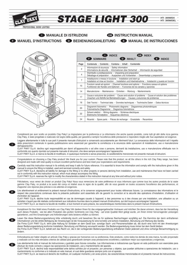
Blocco e sblocco movimento PAN - Figura 3Blocco e sblocco movimento TILT - Figura 4Apertura e chiusura proiettore - Figura 5ATTENZIONE: Il coperchio è montato su una parte mobile dell’apparecchio, è pertanto necessario effettuare con la massima attenzione il montaggio dello stesso perevitare un distacco accidentale. Appoggiare il coperchio facendolo ben combaciare con la parte non asportabile, serrare a fondo entrambe le viti, verificare la perfettatenuta dei filetti.
PAN Mechanism Lock and Release - Fig. 3TILT Mechanism Lock and Release - Fig. 4Opening/closing the projector - Fig. 5WARNING: as the cover is fitted to a moving part of the fixture, maximum care must be taken when refitting to ensure that no accidental separation will occursubsequently. Offer the cover to the non-removable parts, checking for a clean fit, then proceed to tighten both screws, making certain the threads are securely seated.
Blocage et Déblocage mouvement PAN - Figure 3Blocage et Déblocage mouvement TILT - Figure 4Ouverture et fermeture du projecteur - Figure 5ATTENTION : Le couvercle est monté sur une partie mobile de l’appareil. Il est par conséquent nécessaire de procéder à son montage avec la plus grande attention afind’éviter un détachement accidentel. Poser le couvercle en le faisant bien correspondre avec la partie non démontable, serrer à fond les deux vis, vérifier la tenue parfaitedes filets.
Blockierung und Freigabe der PAN-Bewegung - Abb. 3Blockieren und Freigabe der TILT-Bewegung - Abb. 4Öffnen und Schließen des Projektors - Abb. 5ACHTUNG: Der Deckel ist an einem beweglichen Teil des Geräts montiert, deshalb muss bei der Montage besonders sorgfältig vorgegangen werden, damit er sich nichtversehentlich lösen kann. Den Deckel aufsetzen, dabei mit dem nicht abnehmbaren Teil in Übereinstimmung bringen, beide Schrauben fest anziehen und den perfektenHalt der Gewinde überprüfen.
Bloqueo y desbloqueo del movimiento de GIRO - Figura 3Bloqueo y desbloqueo del movimiento de INCLINACIÓN - Figura 4Apertura y cierre del proyector - Figura 5ATENCIÓN: la tapa va montada en una parte móvil del aparato, por lo cual es necesario colocarla con mucho cuidado para evitar que se suelte. Coloque la tapa de maneraque coincida exactamente con su apoyo y apriete a fondo los dos tornillos, verificando la retención de las tuercas.
Continua / Continue
3
STAG
E LIG
HT 3
00
UN
LOCK
ED
LOCK
ED
4
STAG
E LIG
HT 3
00
5
6
STAG
E LIG
HT 3
00
I
GB
D
E
F
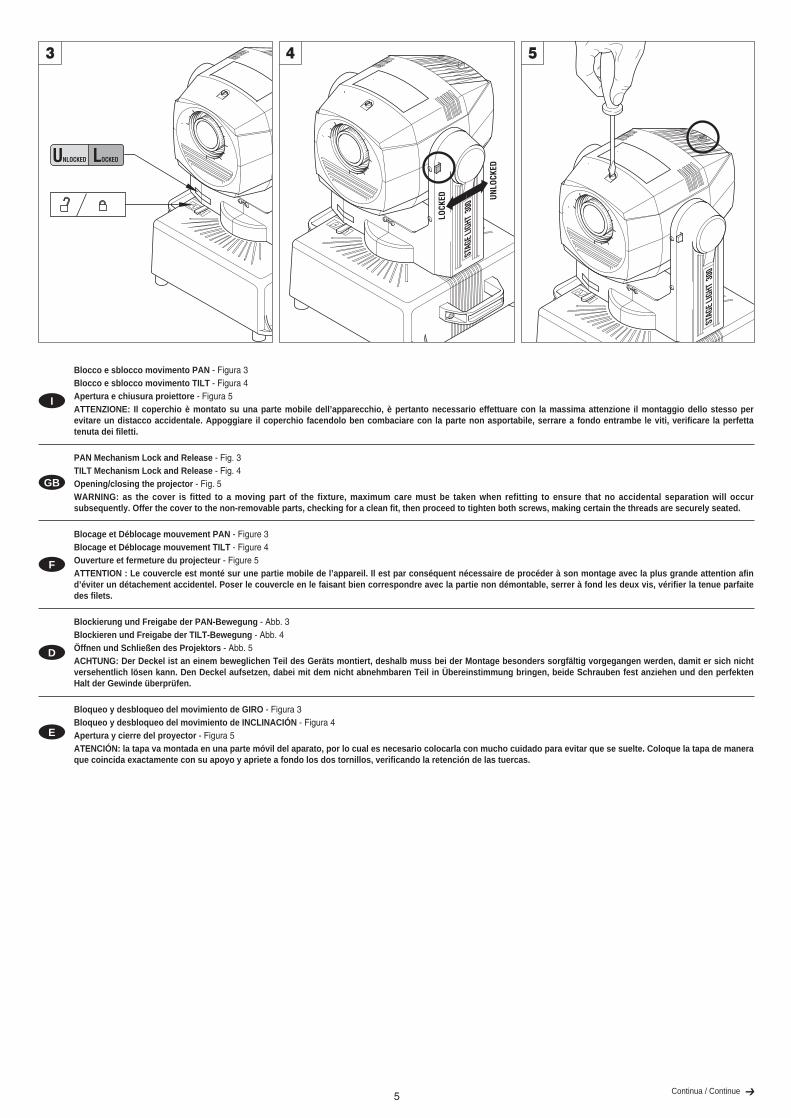
Predisposizione etichetta avvertenze - Figura 6Individuare sul coperchio del corpo mobile l’etichetta cambio lampada e, se necessario, sostituirla con una delle etichette opzionali multilingua poste nel vano lampada del proiettore.ATTENZIONE: Leggere con attenzione ed applicare con scrupolo quanto riportato sull’etichetta in oggetto. Accertarsi inoltre che essa non venga mai rimossa poiché con-tiene importanti informazioni di sicurezza.
Montaggio lampada - Figura 7Togliere la lampada nuova dalla confezione, allentare le due ghiere laterali ed inserire la lampada negli appositi supporti. Infine riavvitare le ghiere.IMPORTANTE: : per avere una distribuzione uniforme del fascio di luce, la lampada deve essere posizionata con la protuberanza, visibile sul bulbo, al di fuori dell’asse ottico delproiettore. A tal fine si consiglia di rivolgere detta protuberanza verso il coperchio superiore del proiettore.ATTENZIONE: il bulbo della lampada non deve essere toccato a mani nude. Se ciò tuttavia dovesse verificarsi, pulire il bulbo stesso con un panno imbevuto d’alcool edasciugarlo con un panno pulito e asciutto.
Preparing the warning label - Fig. 6Find the relamping label on the cover of the movable body and, if necessary, replace it with one of the optional multilingual labels located in the projector lamp compartment.WARNING: Read carefully and meticulously apply the information and instructions given on this label. In addition, check it is never removed as it contains importantsafety information.
Fitting the lamp - Fig. 7Take the new lamp out of its package, loosen the two side ring nuts and insert the lamp in its mountings. Finally, screw on the ring nuts.IMPORTANT: for uniform distribution of the light beam, the lamp must be positioned so that the glass pip on the bulb does not coincide with the optical axis of the projector. With this inmind, locate the pip as high up as possible.WARNING: do not touch the lamp’s envelope with bare hands. Should this happen, clean the bulb with a cloth soaked in alcohol and dry it with a clean, dry cloth.
Prédisposition de l'étiquette de recommandations - Figure 6Identifier sur le couvercle du corps mobile l'étiquette relative au remplacement de la lampe et, si nécessaire, la remplacer par une des étiquettes en plusieurs langues en option situéesdans le logement de la lampe du projecteur.ATTENTION: Lire attentivement et appliquer scrupuleusement les indications fournies sur l'étiquette. En outre, s'assurer que cette étiquette est toujours présente sur l'ap-pareil, car elle fournit d'importantes informations en matière de sécurité.
Montage de la lampe - Figure 7Extraire la lampee neuve de la boîte, desserrer les deux colliers latéraux et introduire la lampe dans les supports. Pour terminer, revisser les colliers.IMPORTANT: pour que le faisceau lumineux soit uniforme, placer l’ampoule de sorte que la protubérance, visible sur le bulbe dépasse l’axe optique du projecteur. À ces fins, il estconseillé de tourner cette protubérance vers le couvercle supérieur du projecteur.ATTENTION: ne pas toucher le bulbe de la lampe avec les doigts. Si cela se produit, nettoyer le bulbe avec un chiffon imbibé d’alcool et le sécher avec un chiffon sec etpropre.
Anbringung der Hinweisschilder - Abb. 6Am Gerätedeckel das Schild des Lampenwechsels ausfindig machen und gegebenenfalls durch eines der in mehreren Sprachen verfügbaren Etiketten ersetzen, die im Lampenfachdes Projektors mitgeliefert werden.ACHTUNG: Lesen Sie die Angaben auf dem fraglichen Etikett aufmerksam durch und halten Sie sich strikt daran. Stellen Sie außerdem sicher, dass es unter keinenUmständen entfernt wird, da es wichtige Sicherheitsinformationen enthält.
Montage der Lampe - Abb. 7Die neue Lampe aus der Verpackung nehmen, die beiden seitlichen Nutmuttern lockern und die Lampe in die Halterungen einsetzen. Dann die Nutmuttern wieder festschrauben.WICHTIG: für einen gleichmäßigen Lichtstrahl muss die Lampe so positioniert werden, dass der auf dem Glaskolben sichtbare Vorsprung außerhalb der optischen Achse desProjektors liegt, d.h. gegen den oberen Projektordeckel gerichtet ist.ACHTUNG: Der Lampenkolben darf nicht mit bloßen Händen berührt werden. Wenn dies dennoch passieren sollte, den Lampenkolben mit einem mit Alkohol getränktenTuch reinigen und ihn mit einem sauberen und trockenen Tuch abtrocknen.
Sustitución de la etiqueta de advertencias - Figura 6Localice en la tapa del cuerpo móvil la etiqueta de cambio de la lámpara y, si es necesario, sustitúyala por una de las etiquetas opcionales en otros idiomas que están en el comparti-miento de la lámpara del proyector.ATENCIÓN: lea con detenimiento las indicaciones de la etiqueta y respételas. Cerciórese de que la etiqueta no se desprenda nunca, porque contiene importantes informa-ciones sobre la seguridad.
Montaje de la lámpara - Figura 7Saque la lámpara nueva del embalaje, afloje las dos virolas laterales y monte la lámpara en los soportes. Vuelva a apretar las virolas.IMPORTANTE: para conseguir una distribución uniforme del haz de luz, la lámpara debe ubicarse con la protuberancia del bulbo fuera del eje óptico del proyector. Se aconseja orien-tarla hacia la tapa superior del proyector.ATENCIÓN: el bulbo de la lámpara no se debe tocar con las manos desnudas. En este caso, limpie el bulbo con un paño humedecido en alcohol y séquela con un pañolimpio yseco.
6
1
2
3
7
7
STAGE LIGHT 300
STAG
E LIG
HT 30
0
STAGE LIGHT 300
I
GB
D
E
F
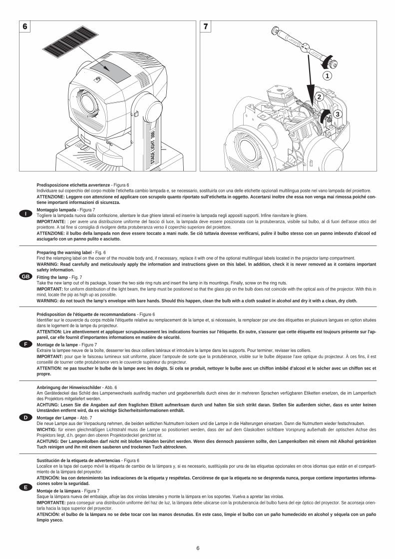
Installazione proiettore - Figura 8Il proiettore può essere installato a pavimento in appoggio sugli appositi gommini, su truss, a soffitto o a parete. Per l’installazione su truss è inoltre disponibile a richiesta la piastra (cod. C61110) con i morsetti ad aggancio/sgancio rapido.ATTENZIONE: Sfruttare tutti e 4 i fori filettati presenti sulla base dell’apparecchio, controllando nel contempo la perfetta tenuta dei filetti.Fissaggio funi di sicurezza - Figura 9.Ad eccezione di quando il proiettore è appoggiato a pavimento, il montaggio delle funi di sicurezza è obbligatorio. Queste devono essere assicurate alla struttura di sostegno delproiettore e quindi agganciate agli anelli presenti sulla base del proiettore stesso.
Installing the projector - Fig. 8The projector can be positioned at loor level standing on the special rubber, on truss, on ceiling or on the wall.A plate (code C61110) with quick-release clamps can also be supplied, on request, for truss mounting.WARNING: use all four holes in the base, checking that the threads are perfectly tight.Fitting the safety wire - Fig. 9The projector must never be erected without the safety wire. The only exception to this rule is when the base stands directly on the floor. The wire is secured to the truss or otherstructure, then anchored to the lugs on the projector itself.
Installation du projecteur - Figure 8Le projecteur peut être monté au sol en appui sur des éléments en caoutchouc antichoc, sur truss, au plafond ou au mur.En outre, la plaque (code C61110) avec les bornes à enclenchement / déclenchement rapide pour l’installation sur truss est disponible sur demande.ATTENTION : Utiliser les 4 trous filetés présents sur la base de l’appareil, et contrôler en même temps la tenue parfaite des filets.Fixation des câbles de sécurité - Figure 9L’installation des câbles de sécurité est obligatoire, sauf lorsque le projecteur est installé au sol. Les fixer sur la structure de soutien du projecteur puis aux anneaux présents sur labase du projecteur.
Installation des Projektors - Abb. 8Der Projektor kann direkt auf dem Fußboden auf den hierzu vorgesehenen stoßfesten Gummifüßen, auf Traversen, an der Decke oder an der Wand installiert werden. Für die Installation auf Rohrträgern ist auf Anfrage außerdem die Platte (Art. Nr. C61110) mit den Klemmen zur schnellen Befestigung/Abnahme erhältlich.ACHTUNG: Alle 4 Gewindebohrungen an der Geräteunterseite nutzen und gleichzeitig den perfekten Halt der Gewinde kontrollieren.Befestigung der Fangseile - Abb. 9Sofern der Projektor nicht auf dem Fußboden installiert ist, ist die Montage der Fangseile zwingend vorgeschrieben. Diese müssen an der Haltestruktur des Projektors befestigt, undanschließend an den Ringen an der Unterseite des Projektors eingehakt werden.
Instalación del proyector - Figura 8El proyector puede instalarse en el suelo apoyado en los tacos de goma, en el truss, al techo o a la pared.Para el montaje en el truss está disponible la placa optional (cód. C61110) con las grapas de sujeción y desenganche rápido.ATENCIÓN: utilice todos los agujeros roscados de la base del aparato y controle que las roscas ejerzan una buena retención.Fijación de las cuerdas de seguridad - Figura 9Salvo cuando el proyector se apoya en el suelo, el montaje de las cuerdas de seguridad es obligatorio. Asegure la cuerda a la estructura de soporte del proyector y engánchela enlos anillos que hay en la base del aparato.
8
STAGE LIGHT 300
9
Continua / Continue
INSTALLAZIONE E MESSA IN FUNZIONE INSTALLATION AND START-UP
INSTALLATION ET MISE EN FONCTION INSTALLATION UND INBETRIEBNAHME INSTALACION Y PUESTA EN FUNCION
I GB
D EF
8
I
GB
D
E
F
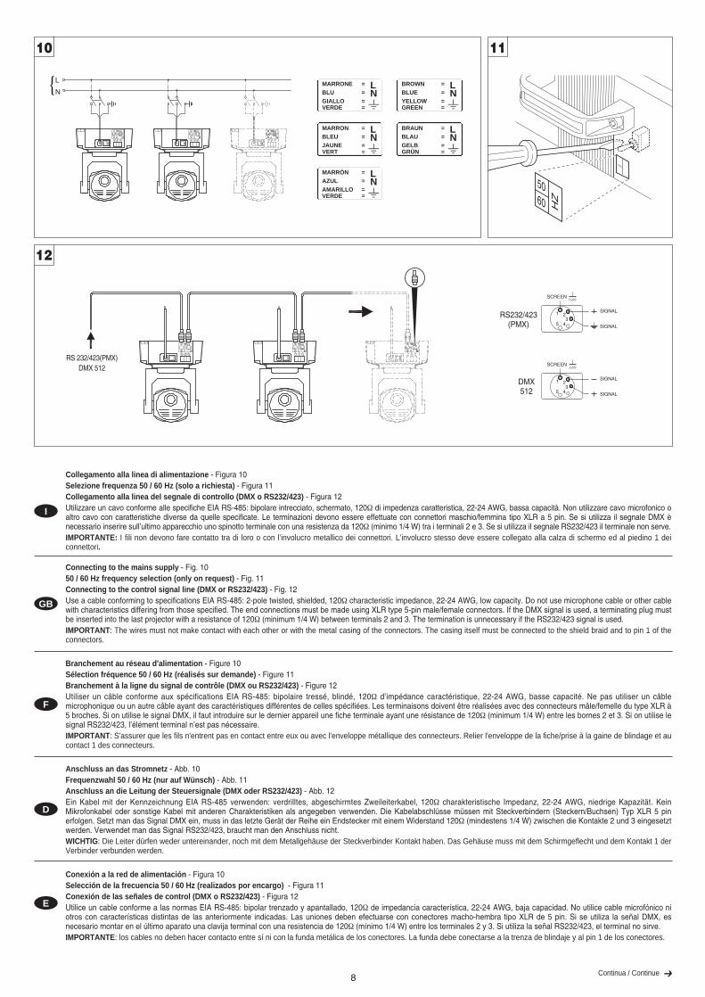
Collegamento alla linea di alimentazione - Figura 10Selezione frequenza 50 / 60 Hz (solo a richiesta) - Figura 11Collegamento alla linea del segnale di controllo (DMX o RS232/423) - Figura 12Utilizzare un cavo conforme alle specifiche EIA RS-485: bipolare intrecciato, schermato, 120Ω di impedenza caratteristica, 22-24 AWG, bassa capacità. Non utilizzare cavo microfonico oaltro cavo con caratteristiche diverse da quelle specificate. Le terminazioni devono essere effettuate con connettori maschio/femmina tipo XLR a 5 pin. Se si utilizza il segnale DMX ènecessario inserire sull’ultimo apparecchio uno spinotto terminale con una resistenza da 120Ω (minimo 1/4 W) tra i terminali 2 e 3. Se si utilizza il segnale RS232/423 il terminale non serve.IMPORTANTE: I fili non devono fare contatto tra di loro o con l’involucro metallico dei connettori. L’involucro stesso deve essere collegato alla calza di schermo ed al piedino 1 deiconnettori.
Connecting to the mains supply - Fig. 1050 / 60 Hz frequency selection (only on request) - Fig. 11Connecting to the control signal line (DMX or RS232/423) - Fig. 12Use a cable conforming to specifications EIA RS-485: 2-pole twisted, shielded, 120Ω characteristic impedance, 22-24 AWG, low capacity. Do not use microphone cable or other cablewith characteristics differing from those specified. The end connections must be made using XLR type 5-pin male/female connectors. If the DMX signal is used, a terminating plug mustbe inserted into the last projector with a resistance of 120Ω (minimum 1/4 W) between terminals 2 and 3. The termination is unnecessary if the RS232/423 signal is used.IMPORTANT: The wires must not make contact with each other or with the metal casing of the connectors. The casing itself must be connected to the shield braid and to pin 1 of theconnectors.
Branchement au réseau d'alimentation - Figure 10Sélection fréquence 50 / 60 Hz (réalisés sur demande) - Figure 11Branchement à la ligne du signal de contrôle (DMX ou RS232/423) - Figure 12Utiliser un câble conforme aux spécifications EIA RS-485: bipolaire tressé, blindé, 120Ω d’impédance caractéristique, 22-24 AWG, basse capacité. Ne pas utiliser un câblemicrophonique ou un autre câble ayant des caractéristiques différentes de celles spécifiées. Les terminaisons doivent être réalisées avec des connecteurs mâle/femelle du type XLR à5 broches. Si on utilise le signal DMX, il faut introduire sur le dernier appareil une fiche terminale ayant une résistance de 120Ω (minimum 1/4 W) entre les bornes 2 et 3. Si on utilise lesignal RS232/423, l’élément terminal n’est pas nécessaire.IMPORTANT: S'assurer que les fils n'entrent pas en contact entre eux ou avec l'enveloppe métallique des connecteurs. Relier l'enveloppe de la fiche/prise à la gaine de blindage et aucontact 1 des connecteurs.
Anschluss an das Stromnetz - Abb. 10Frequenzwahl 50 / 60 Hz (nur auf Wünsch) - Abb. 11Anschluss an die Leitung der Steuersignale (DMX oder RS232/423) - Abb. 12Ein Kabel mit der Kennzeichnung EIA RS-485 verwenden: verdrilltes, abgeschirmtes Zweileiterkabel, 120Ω charakteristische Impedanz, 22-24 AWG, niedrige Kapazität. KeinMikrofonkabel oder sonstige Kabel mit anderen Charakteristiken als angegeben verwenden. Die Kabelabschlüsse müssen mit Steckverbindern (Steckern/Buchsen) Typ XLR 5 pinerfolgen. Setzt man das Signal DMX ein, muss in das letzte Gerät der Reihe ein Endstecker mit einem Widerstand 120Ω (mindestens 1/4 W) zwischen die Kontakte 2 und 3 eingesetztwerden. Verwendet man das Signal RS232/423, braucht man den Anschluss nicht.WICHTIG: Die Leiter dürfen weder untereinander, noch mit dem Metallgehäuse der Steckverbinder Kontakt haben. Das Gehäuse muss mit dem Schirmgeflecht und dem Kontakt 1 derVerbinder verbunden werden.
Conexión a la red de alimentación - Figura 10Selección de la frecuencia 50 / 60 Hz (realizados por encargo) - Figura 11Conexión de las señales de control (DMX o RS232/423) - Figura 12Utilice un cable conforme a las normas EIA RS-485: bipolar trenzado y apantallado, 120Ω de impedancia característica, 22-24 AWG, baja capacidad. No utilice cable microfónico niotros con características distintas de las anteriormente indicadas. Las uniones deben efectuarse con conectores macho-hembra tipo XLR de 5 pin. Si se utiliza la señal DMX, esnecesario montar en el último aparato una clavija terminal con una resistencia de 120Ω (mínimo 1/4 W) entre los terminales 2 y 3. Si utiliza la señal RS232/423, el terminal no sirve.IMPORTANTE: los cables no deben hacer contacto entre sí ni con la funda metálica de los conectores. La funda debe conectarse a la trenza de blindaje y al pin 1 de los conectores.
Continua / Continue
10
HZ
5060
11
SIGNAL
SCREEN
SIGNAL
RS232/423(PMX)
1 23
45
SIGNAL
SCREEN
SIGNAL
5 43
21DMX512
12
L
N
RS 232/423(PMX)DMX 512
MARRONE =BLU =GIALLO =VERDE =
LN
=
BROWN =BLUE =YELLOW =GREEN =
LN
=MARRON =BLEU =JAUNE =VERT =
LN
=
BRAUN =BLAU =GELB =GRÜN =
LN
=MARRÒN =AZUL =AMARILLO =VERDE =
LN
=
9
®
CLAY PAKY spa - Via Pastrengo, 3/b24068 Seriate (BG) - Italy
Tel. +39-035-654311 - www.claypaky.it
ELECTRONICS & SOFTWARE BY PULSAR LIGHT LTD, HENLEY ROAD, CAMBRIDGE, CB1 3EA, UK, EUROPE, PATENTED IN USA, UK, EU
0
12
345
67
8 9
100 10 1
01
234
56
7 8 9
012
34 5 67
89
ADRESS = 000 OR TEST = ON OR
(RE) CALIBRATE SCROLLS:
TOTAL HOURSBULB HOURSBULB STRIKESADRESS
DIGITAL STARTADRESS SELECT
DIGITAL INPUT
LVSERRORDMXPMX
ADRESS / HOURS
PMXRS 232/423
1 = SCREEN2 = SIGNAL3 = SIGNAL4 = NOT USED5 = LVS 18-25 VDC
(MALE ONLY)
DMX1 = SCREEN2 = DATA –3 = DATA +4 = NOT USED5 = LVS 18-25 VDC
(MALE ONLY)
O –
CHANNELASSIGNMENTS
STAGE LIGHT 300
CHANNELASSIGNMENTS
STAGE LIGHT 300
1 2 3 4 5 6 7 8 9 10 11 12
ON
CO
LC
OL
PAN
& T
ILT
8PA
NT
ILT
GO
BO
8
DIS
PLA
Y
16 B
IT
DIS
PLAY
TE
ST
LVS
16 B
IT
+ 1 COLOUR DISC2 GOBO ROTATION3 GOBO CHANGE4 DIMMER/STOPPER/STROBE5 PAN6 TILT7 COLOUR & EFFECTS8 FOCUS9 PAN FINE (OPTION 4 ON)
10 TILT FINE (OPTION 4 ON)11 GOBO FINE (OPTION 7 ON)
01
23
4 5 6
78
9
100 10 001
23
4 5 6
78
9 012
34
5 6 7
89
11
23
4 5 6
78
9
100 10 001
23
4 5 6
78
9
0 1
23416
78 9
0
123
45
6 78
9
100 10 001
23
4 5 6
78
9 012
34 5 6 7
89
01
234
56 7 8 9
100 10 001
23
4 5 6
78
9 012
34
5 6 7
89
I
GB
D
E
F
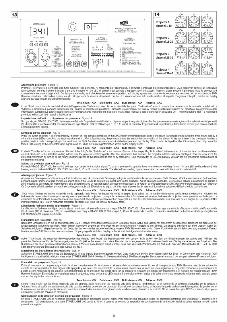
Accensione proiettore - Figura 13Premere l’interruttore e verificare che tutto funzioni regolarmente. Al momento dell’accensione, il software contenuto nel microprocessore DMX Receiver compie un checksum(autocontrollo) durante il quale il display a tre cifre è spento e i tre LED di controllo del segnale d’ingresso sono tutti accesi. Trascorsi alcuni secondi il proiettore inizia la procedura diazzeramento meccanico degli effetti. Contemporaneamente, se il checksum ha avuto esito positivo, sul display appare un codice corrispondente alla versione del microprocessore DMXReceiver installato. Tale codice rimane visualizzato per circa 5 secondi, dopodiché, dei tre LED rimane acceso solo quello relativo al segnale d’ingresso collegato, mentre sul displayscorrono per una volta le seguenti informazioni:
Total hours - XXX Bulb hours - XXX Bulb strikes - XXX Address - XXXin cui “Total hours” sono le ore totali di vita dell’apparecchio, “Bulb hours” sono le ore di vita della lampada, “Bulb strikes” sono il numero di accensioni che la lampada ha effettuato e“Address” è l’indirizzo di partenza selezionato per i segnali di controllo del proiettore. Terminato lo scorrimento, sul display rimane visualizzato l’indirizzo del proiettore. Lo scorrimento delleinformazioni suddette può anche essere generato volontariamente mettendo tutti i selettori rotativi degli indirizzi a zero o ponendo in posizione ON il microinterruttore TEST o mettendo ilproiettore in blackout (tutti i canali a livello zero).Impostazione dell’indirizzo di partenza del proiettore - Figura 14Su ogni singolo STAGE LIGHT 300, deve essere effettuata l’impostazione dell’indirizzo di partenza per il segnale digitale. Per far questo è necessario agire sui tre selettori rotativi per unità(1), decine (10) e centinaia (100) considerando che ogni STAGE LIGHT 300 occupa 8, 10 o 11 canali di controllo. L’operazione di impostazione dell’indirizzo iniziale può essere effettuataanche a proiettore spento.
Switching on the projector - Fig. 13Press the switch checking it all works properly.At switch on, the software contained in the DMX Receiver microprocessor does a checksum (automatic check) while the three figure display isoff and the three LEDs controlling the input signal are all on. After a few seconds, the projector starts the mechanical zero setting of the effects. At the same time, if the checksum has had apositive result, a code corresponding to the version of the DMX Receiver microprocessor (installed) appears on the display. This code is displayed for about 5 seconds, then only one of thethree LEDs relating to the connected input signal stays on, while the following information scrolls on the display once:
Total hours - XXX Bulb hours - XXX Bulb strikes - XXX Address - XXXin which “Total hours” is the total number of hours of the fitting’s life, “Bulb hours” is the number of hours of the lamp’s life, “Bulb strikes” is the number of times the lamp has been switchedon and “Address” is the selected starting address for the projector control signals. After the information has scrolled, the projector address will stay displayed. You can also scroll theaforesaid information by turning all the rotary selector switches of the addresses to zero or by setting the TEST microswitch to ON. Alternatively you can set the projector to blackout (with allthe channels on zero).Setting the projector start address - Fig. 14For each STAGE LIGHT 300, the starting address must be set for the digital signal. To do this, you need to operate three rotary selector switches for unit (1), tens (10) and hundereds (100),bearing in mind that each STAGE LIGHT 300 occupies 8, 10 or 11 control channels. The start address setting operation can also be done with the projector switched off.
Allumage projecteur - Figure 13Appuyer sur l'interrupteur et s'assurer que tout fonctionne bien. Au moment de l'allumage, le logiciel contenu dans le microprocesseur DMX Receiver effectue un checksum (autocontrôle)pendant lequel l'afficheur à trois chiffres est éteint et les trois LEDS de contrôle du signal sont toutes allumées. Après quelques secondes, le projecteur débute la procédure de remise àzéro mécanique des effets. En même temps, si le checksum a eu un résultat positif, un code correspondant à la version du microprocesseur DMX Receiver installé apparaît sur l'afficheur.Ce Code reste affiché pendant environ 5 secondes, puis seule la LED relative au signal d’entrée reste allumée, tandis que les informations suivantes défilent une fois sur l'afficheur:
Total hours - XXX Bulb hours - XXX Bulb strikes - XXX Address - XXX“Total hours” indique les heures totales de vie de l'appareil, “Bulb hours” les heures de vie de la lampe, “Bulb strikes” est le nombre d’allumages que la lampe a effectué et “Address” estl'adresse de départ sélectionnée pour les signaux de contrôle du projecteur. Lorsque le défilement des informations est terminé, l'adresse du projecteur reste présente sur l'afficheur. Ledéfilement des informations susmentionnées peut également être obtenu volontairement en déplaçant sur zéro tous les sélecteurs rotatifs des adresses ou en plaçant sur la position ON lemicrointerrupteur TEST ou en mettant le projecteur en "black-out" (tous les canaux au niveau zéro).Sélection de l’adresse initiale du projecteur - Figure 14La sélection de l’adresse de départ pour le signal numérique doit être effectuée sur chaque STAGE LIGHT 300 . Pour ce faire, il faut agir sur les trois sélecteurs rotatifs relatifs aux unités(1), dizaines (10) et centaines (100), en considérant que chaque STAGE LIGHT 300 occupe 8, 10 ou 11 canaux de contrôle. L’opération desélection de l’adresse initiale peut égalementêtre effectuée avec le projecteur éteint.
Einschalten des Projektors - Abb. 13Nach dem Einschalten führt die im Mikroprozessor DMX Receiver enthaltene Software einen Selbsttest durch, wobei das Display mit drei Ziffern ausgeschaltet bleibt und die drei LEDs derEingangssignal-Steuerung leuchten. Nach einigen Sekunden beginnt der Projektor mit der mechanischen Nullstellung der Effekte. Gleichzeitig erscheint auf dem Display, wenn derSelbsttest erfolgreich abgeschlossen ist, ein Code, der der Version des installierten Mikroprozessor DMX Receivers entspricht. Dieser Code bleibt etwa 5 Sekunden lang angezeigt. Danachleuchtet von den 3 LEDs nur das des verbundenen Eingangssignals. Auf dem Display laufen einmal die folgenden Informationen ab:
Total hours - XXX Bulb hours - XXX Bulb strikes - XXX Address - XXXwobei "Total hours" die gesamten Betriebsstunden des Geräts, "Bulb hours" die Betriebsstunden der Lampe, "Bulb strikes" die Zahl der Einschaltungen der Lampe und "Address" diegewählte Startadresse für die Steuerungssignale des Projektors bedeuten. Nach dem Ablaufen der obengenannten Informationen bleibt am Display die Adresse des Projektors. DasDurchlaufen der oben genannte Informationen kann auf Wunsch auch dadurch erzielt werden, dass man alle Dreh-Wählschalter auf Null stellt, oder den Mikroschalter TEST auf ON stellt,oder den Projektor auf blackout stellt (alle Kanäle auf Null).Einstellung der Startadresse des Projektors - Abb. 14Auf jedem STAGE LIGHT 300 muss die Startadresse für das digitale Signale eingestellt werden. Dazu muss man die drei Dreh-Wählschalter für Einer (1), Zehner (10) und Hunderter (100)betätigen und dabei berücksichtigen, dass jeder STAGE LIGHT 300 8, 10 oder 11 Steuerkanäle belegt. Die Einstellung der Startadresse kann auch bei ausgeschaltetem Projektor erfolgen.
Encendido del proyector - Figura 13Pulse el interruptor y compruebe que todo funcione correctamente. En el momento del encendido, el software contenido en el microprocesador DMX Receiver ejecuta un autocontroldurante el cual la pantalla de tres dígitos está apagada y los tres LEDs de control de la señal están encendidos. Al cabo de unos segundos, el proyector comienza el procedimiento depuesta a cero mecánica de los efectos. Simultáneamente, si el checksum ha tenido éxito, en la pantalla se visualiza un código correspondiente a la versión del microprocesador DMXReceiver instalado. Este código se visualizará unos 5 segundos, luego de los tres LEDs quedará encendido sólo el relativo a la señal de entrada conectada, mientras en la pantalla pasanuna vez las siguientes informaciones:
Total hours - XXX Bulb hours - XXX Bulb strikes - XXX Address - XXXdonde: "Total hours" son las horas totales de vida del aparato, "Bulb hours" son las horas de vida de la lámpara, “Bulb strikes” es el número de encendidos efectuados por la lámpara y"Address" es la dirección de partida seleccionada para las señales de control del proyector. Concluido el desplazamiento, en la pantalla queda la dirección del proyector. Es posible correrla información mencionada poniendo a cero intencionalmente todos los selectores giratorios de las direcciones, llevando a la posición ON el microinterruptor TEST o poniendo el proyectoren blackout (todos los canales en nivel cero).Configuración de la dirección de inicio del proyector - Figura 14En cada STAGE LIGHT 300 es necesario configurar la dirección inicial para la señal digital. Para realizar esta operación, utilice los selectores giratorios para unidades (1), decenas (10) ycentenares (100) considerando que cada STAGE LIGHT 300 ocupa 8, 10 o 11 canales de control. La operación de configuración de la dirección inicial se puede realizar también con elproyector apagado.
13 14
Projector 1channel 1-10
Projector 2channel 11-20
Projector 3channel 21-30
Projector 4channel 31-40
10
CHANNEL EFFECT
1 2 3 4 5 6 7 8 9 10 11 12
ON
CO
L
CO
L
PAN
& T
ILT
8PA
N
TIL
T
GO
BO
8
DIS
PLA
Y
16 B
IT
DIS
PLAY
TE
ST
LVS
16 B
IT
+
Continua / Continue
FUNZIONE CANALI ED OPZIONI CHANNEL FUNCTION AND OPTIONS
FONCTION DES CANAUX ET OPTIONS KANALFUNKTIONEN UND-OPTIONEN FUNCION DE LOS CANALES Y OPCIONES
I GB
D EF
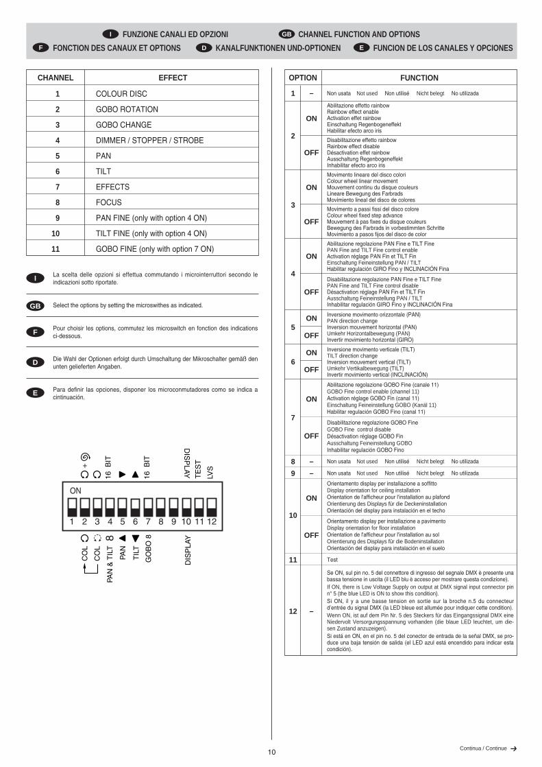
La scelta delle opzioni si effettua commutando i microinterruttori secondo leindicazioni sotto riportate.
Select the options by setting the microswithes as indicated.
Pour choisir les options, commutez les microswitch en fonction des indicationsci-dessous.
Die Wahl der Optionen erfolgt durch Umschaltung der Mikroschalter gemäß denunten gelieferten Angaben.
Para definir las opciones, disponer los microconmutadores como se indica acintinuación.
I
GB
D
E
F
OPTION FUNCTION
2
ON
OFF
Abilitazione effetto rainbowRainbow effect enableActivation effet rainbowEinschaltung RegenbogeneffektHabilitar efecto arco iris
5ON
OFF
6ON
OFF
Inversione movimento orizzontale (PAN)PAN direction changeInversion mouvement horizontal (PAN)Umkehr Horizontalbewegung (PAN)Invertir movimiento horizontal (GIRO)
Inversione movimento verticale (TILT)TILT direction changeInversion mouvement vertical (TILT)Umkehr Vertikalbewegung (TILT)Invertir movimiento vertical (INCLINACIÓN)
Disabilitazione effetto rainbowRainbow effect disableDésactivation effet rainbowAusschaltung RegenbogeneffektInhabilitar efecto arco iris
3
ON
OFF
Movimento lineare del disco coloriColour wheel linear movementMouvement continu du disque couleursLineare Bewegung des FarbradsMovimiento lineal del disco de colores
Movimento a passi fissi del disco coloreColour wheel fixed step advanceMouvement à pas fixes du disque couleursBewegung des Farbrads in vorbestimmten SchritteMovimiento a pasos fijos del disco de color
4
ON
OFF
Abilitazione regolazione PAN Fine e TILT FinePAN Fine and TILT Fine control enableActivation réglage PAN Fin et TILT FinEinschaltung Feineinstellung PAN / TILTHabilitar regulación GIRO Fino y INCLINACIÓN Fina
Disabilitazione regolazione PAN Fine e TILT FinePAN Fine and TILT Fine control disableDésactivation réglage PAN Fin et TILT FinAusschaltung Feineinstellung PAN / TILTInhabilitar regulación GIRO Fino y INCLINACIÓN Fina
COLOUR DISC
GOBO ROTATION
GOBO CHANGE
DIMMER / STOPPER / STROBE
PAN
TILT
EFFECTS
FOCUS
PAN FINE (only with option 4 ON)
TILT FINE (only with option 4 ON)
GOBO FINE (only with option 7 ON)
1
2
3
4
5
6
7
8
9
10
11
7
ON
OFF
Abilitazione regolazione GOBO Fine (canale 11)GOBO Fine control enable (channel 11)Activation réglage GOBO Fin (canal 11)Einschaltung Feineinstellung GOBO (Kanäl 11)Habilitar regulación GOBO Fino (canal 11)
Disabilitazione regolazione GOBO FineGOBO Fine control disableDésactivation réglage GOBO FinAusschaltung Feineinstellung GOBOInhabilitar regulación GOBO Fino
10
12
11
ON
OFF
–
Orientamento display per installazione a soffittoDisplay orientation for ceiling installationOrientation de l'afficheur pour l'installation au plafondOrientierung des Displays für die DeckeninstallationOrientación del display para instalación en el techo
Orientamento display per installazione a pavimentoDisplay orientation for floor installationOrientation de l'afficheur pour l'installation au solOrientierung des Displays für die BodeninstallationOrientación del display para instalación en el suelo
Se ON, sul pin no. 5 del connettore di ingresso del segnale DMX è presente unabassa tensione in uscita (il LED blu è acceso per mostrare questa condizione).If ON, there is Low Voltage Supply on output at DMX signal input connector pinn° 5 (the blue LED is ON to show this condition).Si ON, il y a une basse tension en sortie sur la broche n.5 du connecteurd’entrée du signal DMX (la LED bleue est allumée pour indiquer cette condition).Wenn ON, ist auf dem Pin Nr. 5 des Steckers für das Eingangssignal DMX eineNiedervolt Versorgungsspannung vorhanden (die blaue LED leuchtet, um die-sen Zustand anzuzeigen).Si está en ON, en el pin no. 5 del conector de entrada de la señal DMX, se pro-duce una baja tensión de salida (el LED azul está encendido para indicar estacondición).
8 – Non usata Not used Non utilisé Nicht belegt No utilizada
9 – Non usata Not used Non utilisé Nicht belegt No utilizada
Test
1 – Non usata Not used Non utilisé Nicht belegt No utilizada

11Continua / Continue
• COLOUR DISC - channel 1
Operation with options 2 and 3 OFF
0
1
2
3
4
5
6
7
8
9
10BIT % EFFECT
255 100
128 50.0120 - 127 47.0 - 49.7112 - 119 44.0 - 46.7104 - 111 41.0 - 43.796 - 103 37.5 - 40.588 - 95 34.2 - 37.080 - 87 31.2 - 34.072 - 79 28.2 - 31.064 - 71 25.0 - 28.056 - 63 22.0 - 24.748 - 55 18.7 - 21.740 - 47 15.5 - 18.232 - 39 12.5 - 15.024 - 31 9.5 - 12.016 - 23 6.2 - 9.08 - 15 3.2 - 6.00 - 7 0.0 - 3.0
FAST RAINBOW (300 rpm)
WHITE + REDRED
YELLOW + VIOLET
VIOLET + GREEN
GREEN + ORANGE
ORANGE + BLUE
BLUE + PINK
PINK + WHITE
WHITE
RED + YELLOWYELLOW
VIOLET
GREEN
ORANGE
BLUE
PINK
SLOW RAINBOW (10 rph)
+
OFFON
1 2 3 4 5 6 7 8 9 10 1112
Operation with option 2 ON
0
1
2
3
4
5
6
7
8
9
10BIT % EFFECT
160 - 175 63.0 - 68.7 ORANGE
176 - 191 69.0 - 74.7 ORANGE + BLUE
192 - 207 75.0 - 81.2 BLUE
208 - 223 81.7 - 87.5 BLUE + PINK
224 - 239 88.0 - 93.7 PINK
240 - 255 94.0 - 100 PINK + WHITE
144 - 159 56.2 - 62.5 GREEN + ORANGE
128 - 143 50.0 - 56.0 GREEN
112 - 127 44.0 - 49.7 VIOLET + GREEN
96 - 111 37.5 - 43.7 VIOLET
80 - 95 31.2 - 37 YELLOW + VIOLET
64 - 79 25.0 - 31.0 YELLOW
48 - 63 18.7 - 24.7 RED + YELLOW
32 - 47 12.5 - 18.2 RED
16 - 31 6.2 - 12.0 WHITE + RED
0 - 15 0.0 - 6.0 WHITE
OFFON
1 2 3 4 5 6 7 8 9 10 1112
Operation with option 3 ON
0
1
2
3
4
5
6
7
8
9
10BIT % EFFECT
255 100 WHITE
0 0.0 WHITE
228 89.5 PINK
195 76.2 BLUE
162 63.7 ORANGE
128 50.0 GREEN
97 38.0 VIOLET
63 24.7 YELLOW
31 12.0 RED
OFFON
1 2 3 4 5 6 7 8 9 10 1112
Operation with option 2 and 3 ON
0
1
2
3
4
5
6
7
8
9
10BIT % EFFECT
255
128
113
97
81
64
48
32
16
0
100
50.0
44.2
38.0
31.7
25.0
18.7
12.5
6.2
0.0
RED
WHITE
YELLOW
VIOLET
GREEN
ORANGE
BLUE
PINK
SLOW RAINBOW (10 rph)
FAST RAINBOW (300 rpm)
+
OFFON
1 2 3 4 5 6 7 8 9 10 1112
• GOBO ROTATION - channel 2
0
1
2
3
4
5
6
7
8
9
10
STOP
540°
360°
0°
STOP
FAST (120 rpm)
SLOW (2 rph)
SLOW (2 rph)
FAST (120 rpm)
BIT % EFFECT
191 - 192 74.7 - 75.0
255 100
193 75.5
190 74.2
128 50.0
0 0.0
• GOBO CHANGE - channel 3
0
1
2
3
4
5
6
7
8
9
10 222 - 255 87.0 - 100 GOBO 6
185 - 221 72.5 - 86.7 GOBO 5
148 - 184 58.0 - 72.0 GOBO 4
111 - 147 43.7 - 57.5 GOBO 3
74 - 110 29.0 - 43.2 GOBO 2*
37 - 73 14.2 - 28.7 GOBO 1*
BIT % EFFECT
0 - 36 0.0 - 14 NO GOBO
* Dichroic glass gobo
• DIMMER / STOPPER / STROBE - channel 4
0
1
2
3
4
5
6
7
8
9
10BIT % EFFECT
244 - 255 95.5 - 100 OPEN
0 0.0 CLOSED
128 - 139 50.0 - 54.2 OPEN
243 95.0 FAST STROBE (11 flash/sec.)
140 54.7 SLOW STROBE (1 flash/sec.)

12
Operation with option 5 ON
0
1
2
3
4
5
6
7
8
9
10BIT %
255 100
0 0.0
OFFON
1 2 3 4 5 6 7 8 9 10 1112
• PAN - channel 5
Operation with option 5 OFF
0
1
2
3
4
5
6
7
8
9
10BIT %
255 100
0 0.0
OFFON
1 2 3 4 5 6 7 8 9 10 1112
Operation with option 6 ON
0
1
2
3
4
5
6
7
8
9
10BIT %
255 100
128 50.0
0 0.0
OFFON
1 2 3 4 5 6 7 8 9 10 1112
TILT - channel 6
Operation with option 6 OFF
0
1
2
3
4
5
6
7
8
9
10BIT %
255 100
128 50.0
0 0.0
OFFON
1 2 3 4 5 6 7 8 9 10 1112
• EFFECTS - channel 7
0
1
2
3
4
5
6
7
8
9
10 255 100 LIGHT BLUE
219 86.0 ULTRA VIOLET
184 72.0 PRISM 3 FACE
147 57.5 HEAVY FROST
112 44.0 LIGHT FROST
75 29.5 COLD FILTER
37 14.2 WARM FILTER
BIT % EFFECT
0 0.0 WHITE
• FOCUS - channel 8
BIT % EFFECT
255
00
1
2
3
4
5
6
7
8
9
10 100
0.0
FAR
NEAR
• PAN FINE (only with option 4 ON) - channel 9
Operation with option 5 OFF
0
1
2
3
4
5
6
7
8
9
10BIT %
255 100
0 0.0
OFFON
1 2 3 4 5 6 7 8 9 10 1112
Operation with option 5 ON
0
1
2
3
4
5
6
7
8
9
10BIT %
255 100
0 0.0
OFFON
1 2 3 4 5 6 7 8 9 10 1112

13
• TILT FINE (only with option 4 ON) - channel 10
Operation with option 6 OFF
0
1
2
3
4
5
6
7
8
9
10BIT %
255 100
0 0.0
OFFON
1 2 3 4 5 6 7 8 9 10 1112
Operation with option 6 ON
0
1
2
3
4
5
6
7
8
9
10BIT %
255 100
0 0.0
OFFON
1 2 3 4 5 6 7 8 9 10 1112
Mettendo tutti i canali a livello 0 (blackout), dopo un intervallo di circa 5 secondi,inizia una procedura di ricalibratura degli effetti (tutti eccetto il dimmer cherimane chiuso) grazie alla quale è possibile, dalla centralina di comando,riportare in posizione corretta eventuali effetti motorizzati che durante ilfunzionamento avessero accidentalmente “perso il passo”.L’intero ciclo di ricalibratura ha una durata di circa 40 secondi, e può essereinterrotto in qualsiasi momento, semplicemente impostando un canale a livellosuperiore a 0. Si consiglia tuttavia di non interrompere la ricalibratura, ma dilasciarla terminare regolarmente, una volta trascorsi più di 15 secondi dal suoinizio.
By setting all channels to 0 (blackout), after an interval of about 4 seconds, alleffects (except the dimmer which remains closed) are re-calibrated. It is thenpossible, from the control unit, to reset any motorized effects that duringoperation had accidentally "lost step". The entire re-calibration cycle lasts approximately 40 seconds and can bestopped at any time by simply setting a channel at a level above 0. It isrecommended not to interrupt re-calibration, but to let it end regularly, once 15seconds have elapsed from its start.
En sélectionnant tous les canaux au niveau 0 (blackout), après un intervalled’environ 5 secondes, une procédure de réglage des effets débute (tous leseffets sauf le gradateur, qui reste fermé). Grâce à cette procédure, il estpossible, depuis l’unité de commande, de reporter en position corrected’éventuels effets motorisés qui ont "perdu la synchronisation" pendant lefonctionnement.Le cycle de réglage complet dure environ 40 secondes et il peut être interrompuà tout moment en sélectionnant un canal de niveau supérieur à 0.Il est conseillé de ne pas interrompre le calibrage, mais de le laisser finirrégulièrement, lorsque plus de 15 secondes se sont écoulées depuis le début dela procédure relative.
Stellt man alle Kanäle auf das Niveau 0 (blackout), beginnt nach etwa 5Sekunden ein Nachkalibrierungszyklus der Effekte (alle, ausgenommen der desDimmers, der geschlossen bleibt), dank welcher es möglich ist, von derSteuereinheit aus die motorisierten Effekte, die im Betrieb eventuell ihren„Rhythmus“ verloren haben, in ihre korrekte Position zurückzustellen.Der gesamte Nachkalibrierungszyklus dauert etwa 40 Sekunden und kann injedem Moment ganz einfach unterbrochen werden, indem ein Kanal über 0eingestellt wird. Nach Ablauf von mehr als 15 Sekunden nach Beginn desVorgangs sollte die Nachkalibrierung jedoch möglichst nicht unterbrochen,sondern ordnungsgemäß zu Ende geführt werden.
Configurando todas los canales en nivel 0 (blackout), después de un intervaloaproximado de 5 segundos, inicia un ciclo de recalibración de los efectos (todosa excepción del obscurecedor que permanece cerrado) gracias al cual esposible, por medio de la central de mando, restablecer la correcta posición deposibles efectos motorizados que durante el funcionamiento se hubieran“desajustado”.El ciclo de recalibración dura unos 40 segundos y puede interrumpirse encualquier momento, simplemente definiendo un canal en un nivel superior a 0.Se aconseja no interrumpirlo, y esperar a que termine regularmente, si hanpasado más de 15 segundos desde su inicio.
GB
I
D
E
F
• GOBO FINE (only with option 7 ON) - channel 11
0
1
2
3
4
5
6
7
8
9
10BIT %
255 100
128 50.0
0 0.0
OFFON
1 2 3 4 5 6 7 8 9 10 1112

Blocco e sblocco movimenti Pan e Tilt - Consultare le istruzioni al paragrafo DISIMBALLO E PREDISPOSIZIONE.Apertura e chiusura proiettore - Consultare le istruzioni al paragrafo DISIMBALLO E PREDISPOSIZIONE.Sostituzione lampada - Consultare le istruzioni al paragrafo DISIMBALLO E PREDISPOSIZIONE.Azzeramento ore di funzionamento e numero di accensioni della lampada - Figura 15Per azzerare le ore di vita (Bulb Hours) ed il numero di accensioni (Bulb strikes) della lampada, memorizzate nel microprocessore DMX Receveir, occorre seguire la seguenteprocedura:1. Porre il microinterruttore TEST in posizione ON.2. Spostare il microinterruttore DISPLAY da ON a OFF (o da OFF a ON) e viceversa per tre volte entro un tempo di 6 secondi. Se la procedura è stata eseguita correttamente i tre
LED di controllo del segnale si accendono contemporaneamente mentre il display si spegne. Tale situazione permane per un intervallo di circa 5 secondi.3. Riportare il microinterruttore TEST in posizione OFF.
Locking and releasing Pan and Tilt movements - Refer to the instructions in the UNPACKING AND PREPARATION section.Opening/closing the projector - Refer to the instructions in the UNPACKING AND PREPARATION section.Lamp change - Refer to the instructions in the UNPACKING AND PREPARATION section.Zero setting the working hours and number of times the lamp is switched on - Fig. 15To zero the hours of the lamp’s life (“Bulb hours”) and the number of times it is switched on (“Bulb strikes”) which are stored in the DMX Receiver microprocessor, proceed as follows:1. Set the TEST microswitch to the ON position.2. Shift the DISPLAY microswitch from ON to OFF (or from OFF to ON) and vice versa 3 times within a time of 6 seconds. If the procedure has been carried out correctly, the three
signal control LEDs will light up simultaneously, while the display will go completely blank. This situation lasts for approximately 5 seconds.3. Return the TEST microswitch to the OFF position.
Blocage et déblocage mouvements Pan et Tilt - Consulter les instructions reportées dans le paragraphe DÉBALLAGE ET PRÉPARATION.Ouverture et fermeture du projecteur - Consulter les instructions reportées dans le paragraphe DÉBALLAGE ET PRÉPARATION.Remplacement lampe - Consulter les instructions reportées dans le paragraphe DÉBALLAGE ET PRÉPARATION.Remise à zéro heure de fonctionnement et nombre d’allumages de la lampe - Figure 15Pour remettre à zéro les heures de vie ("Bulb hours") et le nombre d’allumages ("Bulb strikes") de la lampe, mémorisés dans le microprocesseur DMX Receiver, exécuter la procéduresuivante:1. Mettre le micro-interrupteur TEST sur la position ON.2. Faire passer le micro-interrupteur DISPLAY de ON à OFF (ou de OFF à ON) et vice-versa 3 fois en 6 secondes. Si ces opérations ont été effectuées correctement, les trois LEDS
de contrôle du signal s'allument simultanément, tandis que l'afficheur s'éteint complètement. Cette situation dure environ 5 secondes.3. Remettre le micro-interrupteur TEST sur la position OFF.
Sperren und Entsperren der Bewegungen Pan und Tilt - Siehe die Anweisungen im Abschnitt AUSPACKEN UND VORBEREITEN. Öffnen und Schließen des Projektors - Siehe die Anweisungen im Abschnitt AUSPACKEN UND VORBEREITEN. Lampenwechsel - Siehe die Anweisungen im Abschnitt AUSPACKEN UND VORBEREITEN. Nullstellung der Betriebsstunden und der Zahl der Einschaltungen der Lampe - Abb. 15Um die Betriebsstunden ("Bulb hours") und die Zahl der Einschaltungen der Lampe ("Bulb strikes"), die im Mikroprozessor DMX Receiver gespeichert sind, auf Null zu stellen, mussman wie folgt vorgehen:1. Den Mikroschalter TEST auf ON stellen.2. Den Mikroschalter DISPLAY innerhalb 6 Sekunden 3 Mal von ON auf OFF (bzw. von OFF auf ON) stellen und umgekehrt. Wenn der Vorgang korrekt ausgeführt wurde, leuchten
die drei LEDs der Signalkontrolle gleichzeitig auf und das Display wird vollständig ausgeschaltet. Diese Situation bleibt etwa 5 Sekunden lang bestehen.3. Den Mikroschalter TEST wieder auf OFF stellen.
Bloqueo y desbloqueo de los movimientos Pan y Tilt - Consulte las instrucciones el punto DESEMBALAJE Y PREPARACION.Apertura y cierre del proyector - Consulte las instrucciones el punto DESEMBALAJE Y PREPARACION.Cambio de la lámpara - Consulte las instrucciones el punto DESEMBALAJE Y PREPARACION.Puesta a cero de las horas de funcionamiento y número de encendidos de la lámpara - Figura 15Para poner a cero las horas de funcionamiento ("Bulb hours") y el número de encendidos ("Bulb strikes") de la lámpara, almacenados en el microprocesador DMX Receiver, esnecesario seguir este procedimiento:1. Coloque el microinterruptor TEST en la posición ON.2. Conmute el microinterruptor DISPLAY de ON a OFF (o de OFF a ON) y viceversa, tres veces en el término de 6 segundos. Si la operación se ha efectuado correctamente, los tres
LEDs de control de la señal se encienden al mismo tiempo y la pantalla se apaga por completo. Esta situación permanece durante unos 5 segundos.3. Vuelva a situar el microinterruptor TEST en la posición OFF.
14
ELECTRONICS & SOFTWARE BY PULSAR LIGHT LTD, HENLEY ROAD, CAMBRIDGE, CB1 3EA, UK, EUROPE, PATENTED IN USA, UK, EU
ADRESS = 000 OR TEST = ON OR
(RE) CALIBRATE SCROLLS:
TOTAL HOURSBULB HOURSBULB STRIKESADRESS
DIGITAL STARTADRESS SELECT
DIGITAL INPUT
LVSERRORDMXPMX
ADRESS / HOURS
PMXRS 232/423
1 = SCREEN2 = SIGNAL3 = SIGNAL4 = NOT USED5 = LVS 18-25 VDC
(MALE ONLY)
DMX1 = SCREEN2 = DATA –3 = DATA +4 = NOT USED5 = LVS 18-25 VDC
(MALE ONLY)
O –
CHANNELASSIGNMENTS
STAGE LIGHT 300
CHANNELASSIGNMENTS
STAGE LIGHT 300
1 2 3 4 5 6 7 8 9 10 11 12
ON
CO
LC
OL
PAN
& T
ILT
8PA
NT
ILT
GO
BO
8
DIS
PLA
Y
16 B
IT
DIS
PLAY
TE
ST
LVS
16 B
IT
+ 1 COLOUR DISC2 GOBO ROTATION3 GOBO CHANGE4 DIMMER/STOPPER/STROBE5 PAN6 TILT7 COLOUR & EFFECTS8 FOCUS9 PAN FINE (OPTION 4 ON)
10 TILT FINE (OPTION 4 ON)11 GOBO FINE (OPTION 7 ON)
100 10 1
01
234
56
7 8 9 0
12
345
67
8 9
012
34 5 67
89
®
CLAY PAKY spa - Via Pastrengo, 3/b24068 Seriate (BG) - Italy
Tel. +39-035-654311 - www.claypaky.it
I
GB
D
E
F
Continua / Continue
15
MANUTENZIONE MAINTENANCE
ENTRETIEN WARTUNG MANTENIMIENTO
I GB
D EF

15 Continua / Continue
I
GB
D
E
F
Sostituzione filtri colore - Figura 16
Sostituzione gobos - Figura 17
Replacing colour filters - Fig. 16
Replacing gobos - Fig. 17
Remplacement des filtres couleur - Figure 16
Remplacement des gobos - Figure 17
Ersatz der Farbfilter - Abb. 16
Ersatz der gobos - Abb. 17
Sustitución de los filtros de color - Figura 16
Sustitución de los gobos - Figura 17
16
17
Colour Disc
Rosso Red Rouge Rot Rojo 080384/005 Giallo Yellow Jaune Gelb Amarillo 080384/002 Viola Violet Violet Violett Violeta 080384/004 Verde Green Vert Grün Verde 080384/003 Arancio Orange Orange Orange Anaranjado 080384/007 Blu Blue Bleu Blau Azul 080384/001 Rosa Pink Rose Rosa Rosa 080384/006
Effects
Filtro caldo Warm Chaud Warm Caliente 080303/035Filtro freddo Cold Froid Kalt Frío 080384/008Frost leggero Light Frost Frost legér Licht Frost Frost luz 080327/001Frost pesante Heavy Frost Frost laurd Schwerer Frost Frost pesado 080328/001Prisma 3F Prism 3F Prisme 3F Prisma 3F Prisma 081817/001Filtro UV UV filter Filtre UV UV Filter Filtro UV 080303/038Azzurro Light blue Bleu-clair Lichtblau Azul 080384/009
Metal Gobos
Dichroic Gobos
083219/001
083102/001
083213/001
083105/001
083218/001083225/001

STAG
E LIG
HT 3
00
16
I
GB
D
E
F
Pulizia periodica - Figura 18Per mantenere funzionalità e rendimento ottimali per lungo tempo è indispensabile effettuare una pulizia periodica delle parti soggette all’accumulo di polveri e grassi. La frequenzacon la quale effettuare le operazioni sotto indicate dipende da diversi fattori, quali la quantità di movimenti degli effetti e la qualità dell’ambiente di lavoro (umidità dell’aria, presenza dipolvere, salsedine, ecc.).Per rimuovere lo sporco dal riflettore e dai filtri usare un panno morbido inumidito di un qualsiasi liquido detergente per la pulizia del vetro.Annualmente si consiglia di sottoporre il proiettore a personale tecnico qualificato per una manutenzione straordinaria consistente almeno nelle seguenti operazioni:• Controllo visivo e verifica dell’efficacia delle guarnizioni e dei componenti di importanti al fine del mantenimento del grado di protezione IP.• Controllo visivo generale di componenti interni, cablaggio, parti meccaniche, ecc.• Controlli elettrici, fotometrici e funzionali.• Riparazioni eventuali.
Periodical cleaning - Fig. 18To ensure optimal operation and performance for a long time it is essential to periodically clean the parts subject to dust and grease deposits. The frequency with which the followingoperations are to be carried out depends on various factors, such as the amount of the effects and the quality of the working environment (air humidity, presence of dust, salinity, etc.).Use a soft cloth dampened with any detergent liquid for cleaning glass to remove the dirt from the reflectors and filters.It is recommended that the projector undergoes an annual service by a qualified technician for special maintenance involving at least the following operations:• Visual check and verification of the efficiency of the gaskets and the components essential for maintaining the IP protection rating.• General visual check of the internal components, cabling, mechanical parts, etc.• Electrical, photometric and functional checks.• Eventual repairs.
Nettoyage périodique - Figure 18Pour ne pas compromettre le bon fonctionnement et le rendement de l'appareil, nettoyer régulièrement les parties sur lesquelles la poussière et la graisse ont tendance à s'accumuler.La fréquence avec laquelle il faut effectuer les opérations indiquées ci-après dépend de plusieurs facteurs comme la quantité de mouvements des effets et la qualité du lieud’installation (humidité de l’air, présence de poussière, salinité, etc.).Pour enlever la saleté du réflecteur et des filtres, utiliser un chiffon doux imbibé d’un liquide détergent pour le nettoyage des vitres.Il est conseillé de confier une fois par an le projecteur à du personnel technique qualifié pour un entretien extraordinaire qui devra comporter au moins les opérations suivantes:• Contrôle visuel et contrôle de l’efficacité des joints et des composants importants pour assurer le degré de protection IP.• Contrôle visuel général des composants internes, du câblage, des pièces mécaniques, etc..• Contrôles électriques, photométriques et fonctionnels.• Éventuelles réparations.
Regelmäßige Reinigung - Abb. 18Um die optimale Funktionalität und Leistung des Geräts für lange Zeit zu bewahren, ist eine regelmäßige Reinigung der Teile, an denen sich leicht Staub und Fett ansammeln,unverzichtbar. Die Häufigkeit, mit der die nachstehenden Vorgänge durchzuführen sind, hängt von verschiedenen Faktoren ab, wie die Menge Bewegungen der Effektmodule und dieBeschaffenheit der Arbeitsumgebung (Luftfeuchtigkeit, Staub- und Salzhaltigkeit usw.).Zum Reinigen des Reflektors und der Filter ein weiches Tuch verwenden, das mit einem gängigen Glasreinigungsmittel angefeuchtet ist.Einmal jährlich sollte der Projektor außerdem qualifiziertem Fachpersonal übergeben werden, um ihn einer außerordentlichen Wartung zu unterziehen, die mindestens folgendeArbeiten umfasst:• Sichtprüfung und Prüfung der Leistungsfähigkeit der Dichtungen und der wichtigen Bauteile zu dem Zweck, den Schutzgrad IP zu erhalten.• Allgemeine Sichtkontrolle der inneren Bauteile, Verdrahtungen, mechanischen Teile usw.• Elektrische, fotometrische und funktionelle Kontrollen.• Eventuelle Reparaturen.
Limpieza periódica - Figura 18Para conservar las prestaciones y el rendimiento del proyector durante mucho tiempo, es indispensable limpiar periódicamente las partes donde se depositan polvos y grasas. Lafrecuencia de la limpieza depende de varios factores, como la cantidad de movimientos de los efectos y las características del ambiente de trabajo (humedad del aire, presencia depolvo, salinidad, etc.).Para limpiar el reflector y los filtros, utilice un paño suave humedecido en cualquier limpiacristales no corrosivo.Se aconseja hacer revisar el proyector una vez al año par personal técnico cualificado para que realice un mantenimiento extraordinario consistente, como mínimo, en las siguientesoperaciones:• Control visual y comprobación de la eficiencia de las guarniciones y componentes principales para mantener el grado de protección IP.• Control visual general de componentes internos, cableado, partes mecánicas, etc.• Controles eléctricos, fotométricos y de funcionamiento.• Posibles reparaciones.
18
Parti che necessitano di una pulizia frequente.Parts requiring frequent cleaning.Pièces qui doivent être nettoyées fréquemment.Teile, die häufig gereinigt werden müssen.Partes que necesitan limpieza frecuente.
Parti che necessitano di una pulizia mensile.Parts requiring monthly cleaning.Pièces qui doivent être nettoyées mensuellement.Teile, die einmal monatlich gereinigt werden müssen.Partes que necesitan limpieza mensual.
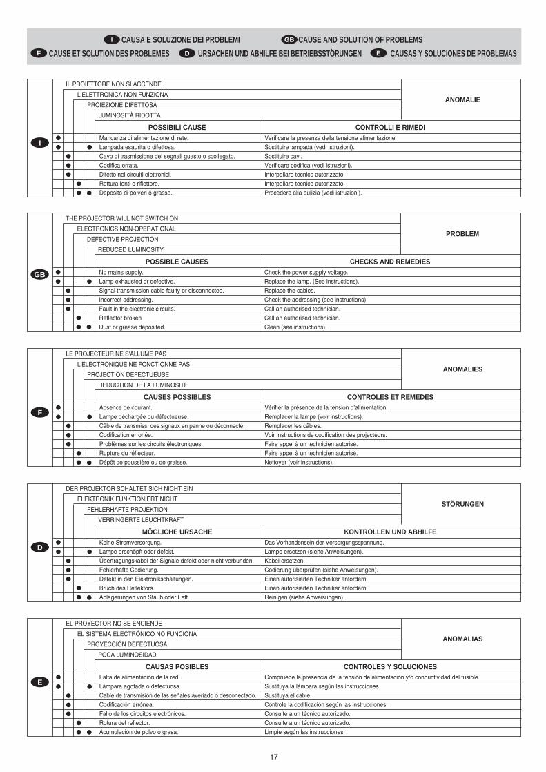
17
IL PROIETTORE NON SI ACCENDE
ANOMALIEL’ELETTRONICA NON FUNZIONA
PROIEZIONE DIFETTOSA
LUMINOSITÀ RIDOTTA
POSSIBILI CAUSE CONTROLLI E RIMEDIMancanza di alimentazione di rete.Lampada esaurita o difettosa.Cavo di trasmissione dei segnali guasto o scollegato.Codifica errata.Difetto nei circuiti elettronici.Rottura lenti o riflettore.Deposito di polveri o grasso.
Verificare la presenza della tensione alimentazione. Sostituire lampada (vedi istruzioni).Sostituire cavi.Verificare codifica (vedi istruzioni).Interpellare tecnico autorizzato.Interpellare tecnico autorizzato.Procedere alla pulizia (vedi istruzioni).
I
LE PROJECTEUR NE S'ALLUME PAS
ANOMALIESL'ELECTRONIQUE NE FONCTIONNE PAS
PROJECTION DEFECTUEUSE
REDUCTION DE LA LUMINOSITE
CAUSES POSSIBLES CONTROLES ET REMEDESAbsence de courant.Lampe déchargée ou défectueuse.Câble de transmiss. des signaux en panne ou déconnecté.Codification erronée.Problèmes sur les circuits électroniques.Rupture du réflecteur.Dépôt de poussière ou de graisse.
Vérifier la présence de la tension d’alimentation.Remplacer la lampe (voir instructions).Remplacer les câbles.Voir instructions de codification des projecteurs.Faire appel à un technicien autorisé.Faire appel à un technicien autorisé.Nettoyer (voir instructions).
F
DER PROJEKTOR SCHALTET SICH NICHT EIN
STÖRUNGENELEKTRONIK FUNKTIONIERT NICHT
FEHLERHAFTE PROJEKTION
VERRINGERTE LEUCHTKRAFT
MÖGLICHE URSACHE KONTROLLEN UND ABHILFEKeine Stromversorgung.Lampe erschöpft oder defekt.Übertragungskabel der Signale defekt oder nicht verbunden.Fehlerhafte Codierung.Defekt in den Elektronikschaltungen.Bruch des Reflektors.Ablagerungen von Staub oder Fett.
Das Vorhandensein der Versorgungsspannung.Lampe ersetzen (siehe Anweisungen).Kabel ersetzen.Codierung überprüfen (siehe Anweisungen).Einen autorisierten Techniker anfordern.Einen autorisierten Techniker anfordern.Reinigen (siehe Anweisungen).
D
EL PROYECTOR NO SE ENCIENDE
ANOMALIASEL SISTEMA ELECTRÓNICO NO FUNCIONA
PROYECCIÓN DEFECTUOSA
POCA LUMINOSIDAD
CAUSAS POSIBLES CONTROLES Y SOLUCIONESFalta de alimentación de la red.Lámpara agotada o defectuosa.Cable de transmisión de las señales averiado o desconectado.Codificación errónea.Fallo de los circuitos electrónicos.Rotura del reflector.Acumulación de polvo o grasa.
Compruebe la presencia de la tensión de alimentación y/o conductividad del fusible.Sustituya la lámpara según las instrucciones.Sustituya el cable.Controle la codificación según las instrucciones.Consulte a un técnico autorizado.Consulte a un técnico autorizado.Limpie según las instrucciones.
E
CAUSA E SOLUZIONE DEI PROBLEMI CAUSE AND SOLUTION OF PROBLEMS
CAUSE ET SOLUTION DES PROBLEMES URSACHEN UND ABHILFE BEI BETRIEBSSTÖRUNGEN CAUSAS Y SOLUCIONES DE PROBLEMAS
I GB
D EF
THE PROJECTOR WILL NOT SWITCH ON
PROBLEMELECTRONICS NON-OPERATIONAL
DEFECTIVE PROJECTION
REDUCED LUMINOSITY
POSSIBLE CAUSES CHECKS AND REMEDIESNo mains supply.Lamp exhausted or defective.Signal transmission cable faulty or disconnected.Incorrect addressing.Fault in the electronic circuits.Reflector brokenDust or grease deposited.
Check the power supply voltage.Replace the lamp. (See instructions).Replace the cables.Check the addressing (see instructions)Call an authorised technician.Call an authorised technician.Clean (see instructions).
GB

18
Alimentazione- 230V 50Hz - 120V 60Hz- 240V 50Hz - 100V 50Hz- 208V 60Hz - 100V 60Hz- 200V 50Hz- 200V 60Hz
Il proiettore è predisposto per il funzionamento a tensione e frequen-za indicate sull’etichetta dei dati elettrici posta sulla base dell’appa-recchio.
Potenza assorbita• Versioni 200-240V 50/60Hz: 600VA a 230V 50Hz (Rifasamento
35µF Standard)• Versioni 100-120V 50/60Hz: 900VA a 120V 60Hz
LampadaA ioduri metallici alimentata tramite speciale alimentatore incorpora-to.• Tipo HTI 300W/DX
- Attacco SFc 10-4- Temperatura colore 6500 K- Flusso luminoso 22000 lm- Vita media 750 h- Posizione di lavoro qualsiasi
• Tipo HTI 300W/DEL- Attacco SFc 10-4- Temperatura colore 5700 K- Flusso luminoso 20000 lm- Vita media 3000 h- Posizione di lavoro qualsiasi (per proiettori a corpo mobile)
MotoriN. 9 motori passo-passo, funzionanti a micropassi, totalmente con-trollati da microprocessore.
Gruppo ottico• Base in alluminio pressofuso.• Condensatore a doppia lente.• Riflettore sferico ad elevata resa luminosa.
Obiettivi• Standard: Zoom 75-115 mm (17,6°-23,8°)• Opzionale: Zoom 115-170 mm (11,6°-16,2°)
CanaliN. 8, 10 o 11 canali di controllo.
Ingressi• RS232/423(PMX)• DMX 512
Corpo mobile• Movimento tramite due motori a micropassi, controllati da micro-
processore.• Riposizionamento automatico di PAN e TILT in seguito a sposta-
menti accidentali non comandati da centralina.• Escursione:
- PAN = 450°- TILT = 252°
• Velocità massime:- PAN = 2.4 sec (360°)- TILT = 2.0 sec (252°)
• Risoluzione:- PAN = ±1.76°- PAN FINE = ±0.007°- TILT = ±0.98°- TILT FINE = ±0.004°
Grado di protezione IP20• Protetto contro la penetrazione di corpi solidi di dimensione supe-
riore a 12mm.• Nessuna protezione contro la penetrazione di liquidi.
Marcatura CEConforme alle Direttive dell’Unione Europea di Bassa Tensione73/23 e Compatibilità Elettromagnetica 89/336.
Dispositivi di sicurezza• Interruttore automatico bipolare a protezione termica.• Interruzione automatica dell’alimentazione in caso di surriscalda-
mento o di mancato funzionamento del sistema di raffreddamento.• Disinserimento automatico dell’alimentazione all’apertura del
coperchio.• Due punti di fissaggio per fune di sicurezza.
RaffreddamentoA ventilazione forzata tramite ventole assiali.
Corpo• In alluminio pressofuso ed acciaio.• Verniciatura a polveri epossidiche.• Due maniglie laterali per il trasporto.• Dispositivo di bloccaggio dei movimenti PAN e TILT per trasporto
e manutenzione.
Posizione di lavoroFunzionamento in qualsiasi posizione.
Pesi e dimensioni• Versioni 200-240V: 22,5 kg.• Versioni 100-120V: 23,6 kg
Power supplies available- 230V 50Hz - 120V 60Hz- 240V 50Hz - 100V 50Hz- 208V 60Hz - 100V 60Hz- 200V 50Hz- 200V 60Hz
The projector is designed to operate at the mains frequency andvoltage given on the electrical data label on the base of theappliance.
Input power• 200-240V 50/60Hz versions: 600VA a 230V 50Hz
(p.f. correction 35µF standard).• 100-120V 50/60Hz versions: 900VA a 120V 60Hz
LampMetal halide type with special built-in power supply unit.
• Type of lamp HTI 300W/DX- fitting SFc 10-4- colour temperature 6500 K- luminous flux 22000 lm- average life 750 h- Operation in any position
• Type of lamp HMD 300W/DEL- fitting SFc 10-4- colour temperature 5700 K- luminous flux 20000 lm- average life 3000 h- Operation in any position (moving body projectors)
Motors9 stepper motors, operating with microsteps, totally microproces-sor controlled.
Optical unit• Main unit in diecast aluminium.• Twin lens condenser.• Spherical reflector with high luminous efficiency.
Lenses• Standard: Zoom 75-115 mm (17,6°-23,8°)• Option: Zoom 115-170 mm (11,6°-16,2°)
Channels8, 10 or 11 control channels.
Inputs• RS232/423(PMX)• DMX 512
Movable body• Movement by means two stepper motors, controlled by micro-
processor.• Automatic repositioning of PAN and TILT following accidental
movements not piloted by controller.• Travel:
- PAN = 450°- TILT = 252°
• Maximum speeds:- PAN = 2.4 sec (360°)- TILT = 2.0 sec (252°)
• Resolution:- PAN = ±1.76°- PAN FINE = ±0.007°- TILT = ±0.98°- TILT FINE = ±0.004°
IP20 protection rating• Protected against the entry of solid bodies larger than 12mm
(0.47”).• No protection against the entry of liquids.
CE MarkingIn conformity with the European Union Low Voltage Directive73/23 and Electromagnetic compatibility Directive 89/336.
Safety Devices• Automatic two pole thermal cutout.• Automatic break in power supply in case of overheating or fai-
led operation of cooling system• Power supply cut off automatically on opening the cover.• Two fixing points for safety wire.
CoolingForced ventilation cooling system using axial flow fans.
Body• In die-cast aluminium and steel.• Epoxy powder painting.• Two side handles for transportation.• Device locking PAN and TILT mechanisms for transportation
and maintenance.
Working positionFunctioning in any position.
Weights and dimensions• 200-240V versions: 22,5 kg (49 lbs 8 ozs).• 100-120V versions: 23,6 kg (51 lbs 15 ozs).
DATI TECNICI TECHNICAL INFORMATIONI GB
(11.89'')300
(20.47'')520
STAG
E LIG
HT 3
00
(15.75'')400
(11.89'')300
(18.90'')480
(15.75'')400
STAG
E LIG
HT 3
00
230V 50Hz
240V 50Hz
208V 60Hz
200V 50Hz
200V 60Hz
120V 60Hz
100V 50Hz
100V 60Hz

19
Vorhandene Netzversorgung- 230V 50Hz - 120V 60Hz- 240V 50Hz - 100V 50Hz- 208V 60Hz - 100V 60Hz- 200V 50Hz- 200V 60Hz
Der Projektor ist für den Betrieb bei der auf dem Typenschild andem Gerätesockel angegebenen Spannung und Frequenzausgelegt.
Leistungsaufnahme• Versionen 200-240V 50/60Hz: 600VA bei 230V 50Hz
(Blindstromkompensation 35µF Standard)• Versionen 100-120V 50/60Hz: 900VA bei 120V 60Hz.
LampeJodid-Metalldampflampen, Versorgung mit speziellem, in dasGerät eingebautem orschaltgerät.• Typ HTI 300W/DX
- Sockel SFc 10-4- Farbtemperatur 6500 K- Lichtfluss 22000 lm- Durchschnittliche Lebensdauer 750 h- Beliebige Einbauposition
• Typ HTI 300W/DEL- Sockel SFc 10-4- Farbtemperatur 5700 K- Lichtfluss 20000 lm- Durchschnittliche Lebensdauer 3000 h- Beliebige Einbauposition
Motoren9 Mikro-Schrittmotoren, vollständig mikroprozessorgesteuert.
Optikgruppe• Basis aus Aluminiumdruckguß• DoppellinsenKondensor.• Kugelreflektor mit hoher Lichtausbeute.
Objektive• Standard: Zoom 75-115 mm (17,6°-23,8°).• Optional: Zoom 115-170 mm (11,6°-16,2°).
Kanäle 8, 10 oder 11 Steuerkanäle.
Eingänge• RS232/423 (PMX)• DMX 512
Beweglicher Kopf• Bewegung durch zwei mikroprozes-sorgesteuerte Mikro-
Schrittmotoren.• Automatische Rückpositionierung von PAN und TILT nach
unbeabsichtigten, nicht vom Regiepult betätigten Bewegungen.• Aktionsradius:
- PAN = 450°- TILT = 252°
• Höchstgeschwindigkeit:- PAN = 2.4 sec (360°)- TILT = 2.0 sec (252°)
• Auflösung:- PAN = ±1.76°- PAN FINE = ±0.007°- TILT = ±0.98°- TILT FINE = ±0.004°
Schutzklasse IP20• Schutz gegen das Eindringen fester Körper, die größer sind als
12mm.• Kein Schutz gegen das Eindringen von Flüssigkeiten.
CE-KennzeichnungEntspricht den Richtl inien der Europäischen Union(Niederspannungsrichtl inie 73/23; elektromagnetischeVerträglichkeit 89/336).
Sicherheitsvorrichtungen• Zweipoliger Wärmeschutz-Sicherheitsschalter.• Automatische Abschaltung der Stromzufuhr bei Überhitzung
oder Ausfall des Kühlsystems.• Automatische Abschaltung bei Öffnung der Serviceluke.• Zwei Befestigungsösen für Fangseil.
KühlungKühlsystem mit Zwangslüftung durch Axiallüfter.
Gehäuse• Druckgussaluminium und Stahl.• Epoxydpulverbeschichtung.• Zwei seitliche Tragegriffe.• PAN- und TILT-Arretierung für Transport und Wartung.
EinbaupositionBeliebige Einbauposition, Einschrän-kung je nachCharakteristiken der verwendeten Lampe.
Maße und Gewichte• Versionen 200-240V: 22,5 kg.• Versionen 100-120V: 23,6 kg.
Alimentaciones disponibles- 230V 50Hz - 120V 60Hz- 240V 50Hz - 100V 50Hz- 208V 60Hz - 100V 60Hz- 200V 50Hz- 200V 60Hz
El proyector está preparado para funcionar a la tensión yfrecuencia indicadas la base del aparato.
Potencia absorbida• Versión 200-240V 50/60Hz: 600VA a 230V 50Hz
(ajuste de fase 35µF de serie)• Versión 100-120V 50/60Hz: 900VA a 120V 60Hz.
LámparaDe yoduros metálicos, abastecida por un alimentador especialincorporado en el aparato.• Tipo HTI 300W/DX
- Casquillo SFc 10-4- Temperatura de color 6500 K- Flujo luminoso 22000 lm- Vida media 750 h- Posición de trabajo: cualquiera
• Tipo HTI 300W/DEL- Casquillo SFc 10-4- Temperatura de color 5700 K- Flujo luminoso 20000 lm- Vida media 3000 h- Posición de trabajo: cualquiera
MotoresN. 9 motores de micropasos totalmente controlados pormicroprocesador.
Grupo óptic• Base de aluminio inyectado• Condensador de doble lente.• Reflector esférico de elevado rendimiento lumínico.
Objetivos• De serie: Zoom 75-115 mm (17,6°-23,8°).• Opcional: Zoom 115-170 mm (11,6°-16,2°)
Canales8, 10 ó 11 canales de control
Entradas• RS232/423(PMX)• DMX 512
Cuerpo móvil• Movimiento mediante dos motores de micropasos controlados
por microprocesador.• Reposicionamiento automático de giro e inclinación tras
desplazamientos accidentales no accionados desde la consola.• Excursión:
- GIRO = 450°- INCLINACIÓN = 252°
• Velocidades máximas:- GIRO = 2.4 sec (360°)- INCLINACIÓN = 2.0 sec (252°)
• Resolución:- GIRO = ±1.76°- GIRO FINO = ±0.007°- INCLINACIÓN = ±0.98°- INCLINACIÓN FINA = ±0.004°
Grado de protección IP20• Protegido contra la entrada de cuerpos sólidos de dimensiones
superiores a 12 mm.• Ninguna protección contra la entrada de agua..
Marcado CEConforme a las Directrices de la Unión Europea de Baja Tensión73/23 y Compatibilidad Electromagnética 89/336.
Dispositivos de seguridad• Interruptor automático bipolar con protección térmica.• Desconexión automática de la alimentación en caso de
recalentamiento o de fallo del sistema de enfriamiento.• Desconexión automática de la alimentación al abrirse la tapa.• Dos puntos de fijación para cuerda de seguridad.
EnfriamientoPor ventilación forzada con ventiladores axiales.
Cuerpo• De aluminio moldeado a presión y extrusionado.• Pintado con resina epoxi en polvo.• Dos asas laterales para el transporte.• Bloqueo de los movimientos de giro e inclinación para
transporte y mantenimiento.
Posición de trabajoFunciona en cualquier posición.
Pesos y medidas• Versiones 200-240V: 22,5 kg.• Versiónes 100-120V: 23,6 kg.
TECHNISCHE DATEN DATOS TÉCNICOS
Alimentations disponibles- 230V 50Hz - 120V 60Hz- 240V 50Hz - 100V 50Hz- 208V 60Hz - 100V 60Hz- 200V 50Hz- 200V 60Hz
Le projecteur est prédisposé pour le fonctionnement aux valeursde tension et de fréquence indiquées sur l'étiquette des donnéesélectriques située sur la base de l'appareil.
Puissance absorbée• Versions 200-240V 50/60Hz: 600VA à 230V 50Hz (Rephasage
35µF en standard).• Versions 100-120V 50/60Hz: 900VA à 120V 60Hz.
LampeA iodures métalliques, alimentée par un dispositif spécialincorporé dans l'appareil.• Type HTI 300W/DX
- Culot SFc 10-4- Température couleur 6500 K- Flux lumineux 22000 lm- Durée de Vie moyenne 750 h- Toutes les positions de travail
• Type HTI 300W/DEL- Culot SFc 10-4- Température couleur 5700 K- Flux lumineux 20000 lm- Durée de Vie moyenne 3000 h- Toutes les positions de travail
MoteursN. 9 moteurs pas-à-pas, fonctionnant par micropas, totalementcontrôlés par microprocesseur.
Groupe optique• Base en aluminium moulé sous pression.• Condensateur à double lentille.• Réflecteur sphérique à haut rendement lumineux.
Objectifs• Standard: Zoom 75-115 mm (17,6° - 23,8°).• Option: Zoom 115-70 mm (11,6° - 16,2°).
Canaux 8, 10 ou 11 canaux de contrôle
Entrées• RS232/423 (PMX)• DMX 512
Corps mobile• Mouvement fourni par deux moteurs à micropas commandés
par micro-processeur.• Remise en position automatique de PAN et TILT après des
déplacements accidentels non commandés par la centrale.• Excursion:
- PAN = 450°- TILT = 252°
• Vitesses maximum:- PAN = 2.4 sec (360°)- TILT = 2.0 sec (252°)
• Résolution:- PAN = ±1.76°- PAN FINE = ±0.007°- TILT = ±0.98°- TILT FINE = ±0.004°
Degré de protection IP20• Protégé contre la pénétration de corps solides ayant une
dimension supérieure à 12mm.• Aucune protection contre la pénétration de liquides.
Marquage CEConforme aux Directives de l’Union Européenne Basse Tension73/23 et Compatibilité Electromagnétique 89/336.
Dispositifs de sécurité• Interrupteur automatique bipolaire à protection thermique.• Coupure automatique de l'alimentation en cas de surchauffe
ou de panne du système de refroidissement.• Coupure automatique de l'alimentation lorsque le couvercle s’ ouvre.• Deux points de fixation pour câble de sécurité.
RefroidissementA ventilation forcée par ventilateurs axiaux.
Corps• En aluminium moulé sous pression et acier.• Peint aux poudres époxy.• Deux poignées latérales pour le transport.• Dispositif de blocage des mouvements PAN et TILT pour
transport et entretien.
Position de travailFonctionne dans toutes les positions.
Poids et dimensions• Versions 200-240V: 22,5 kg.• Versions 100-120V: 23,6 kg.
DONNEES TECHNIQUES D EF