GENERATORE D'ARIA CALDA A GAS NATURALE/G.P.L. … · l-l 166.00-bm manuale d’uso e manutenzione...
40
GENERATORE D'ARIA CALDA A GAS NATURALE/G.P.L. GENERATEUR D'AIR CHAUD AU GAS NATUREL/G.P.L. WARMLUFTERZEUGER MIT ERDGAS-/FLÜSSIGGASBETRIEB NATURAL GAS /L.P.G. SPACE HEATER GENERADOR DE AIRE CALIENTE A GAS NATURAL/G.P.L. ТЕПЛОВОЙ ГЕНЕРАТОР НА ПРИРОДНОМ ГАЗЕ / СНГ 0694BU2235 GA/N 45C L-L 166.00-BM MANUALE D’USO E MANUTENZIONE MANUEL D'INSTRUCTIONS BETRIEBSANLEITUNG INSTRUCTIONS MANUAL MANUAL DE INSTRUCCIONES РУКОВОДСТВО ПО ЭКСПЛУАТАЦИИ И ТЕХОБСЛУЖИВАНИЮ
-
Upload
phungtuong -
Category
Documents
-
view
219 -
download
0
Transcript of GENERATORE D'ARIA CALDA A GAS NATURALE/G.P.L. … · l-l 166.00-bm manuale d’uso e manutenzione...
GENERATORE D'ARIA CALDA A GAS NATURALE/G.P.L. GENERATEUR D'AIR CHAUD AU GAS NATUREL/G.P.L. WARMLUFTERZEUGER MIT ERDGAS-/FLÜSSIGGASBETRIEB NATURAL GAS /L.P.G. SPACE HEATER GENERADOR DE AIRE CALIENTE A GAS NATURAL/G.P.L. ТЕПЛОВОЙ ГЕНЕРАТОР НА ПРИРОДНОМ ГАЗЕ / СНГ
0694BU2235
GA/N 45C
L-L 166.00-BM
MANUALE D’USO E MANUTENZIONE MANUEL D'INSTRUCTIONS BETRIEBSANLEITUNG INSTRUCTIONS MANUAL MANUAL DE INSTRUCCIONES РУКОВОДСТВО ПО ЭКСПЛУАТАЦИИ И ТЕХОБСЛУЖИВАНИЮ

3
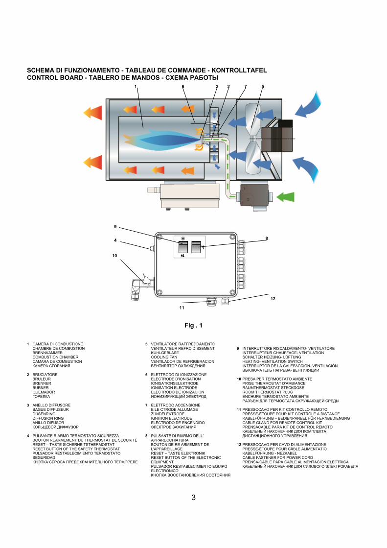
SCHEMA DI FUNZIONAMENTO - TABLEAU DE COMMANDE - KONTROLLTAFEL CONTROL BOARD - TABLERO DE MANDOS - СХЕМА РАБОТЫ
Fig . 1
1 CAMERA DI COMBUSTIONE
CHAMBRE DE COMBUSTION BRENNKAMMER COMBUSTION CHAMBER CAMARA DE COMBUSTION КАМЕРА СГОРАНИЯ
2 BRUCIATORE
BRULEUR BRENNER BURNER QUEMADOR ГОРЕЛКА
3 ANELLO DIFFUSORE
BAGUE DIFFUSEUR DÜSENRING DIFFUSION RING ANILLO DIFUSOR КОЛЬЦЕВОЙ ДИФФУЗОР
4 PULSANTE RIARMO TERMOSTATO SICUREZZA
BOUTON RÉARMEMENT DU THERMOSTAT DE SÉCURITÉ RESET – TASTE SICHERHEITSTHERMOSTAT RESET BUTTON OF THE SAFETY THERMOSTAT PULSADOR RESTABLECIMIENTO TERMOSTATO SEGURIDAD КНОПКА СБРОСА ПРЕДОХРАНИТЕЛЬНОГО ТЕРМОРЕЛЕ
5 VENTILATORE RAFFREDDAMENTO VENTILATEUR REFROIDISSEMENT KUHLGEBLASE COOLING FAN VENTILADOR DE REFRIGERACION ВЕНТИЛЯТОР ОХЛАЖДЕНИЯ
6 ELETTRODO DI IONIZZAZIONE
ELECTRODE D'IONISATION IONISATIONSELEKTRODE IONISATION ELECTRODE ELECTRODO DE IONIZACION ИОНИЗИРУЮЩИЙ ЭЛЕКТРОД
7 ELETTRODO ACCENSIONE
E LE CTRODE ALLUMAGE ZÜNDELEKTRODE IGNITION ELECTRODE ELECTRODO DE ENCENDIDO ЭЛЕКТРОД ЗАЖИГАНИЯ
8 PULSANTE DI RIARMO DELL’
APPARECCHIATURA BOUTON DE RE ARMEMENT DE L'APPAREILLAGE RESET – TASTE ELEKTRONIK RESET BUTTON OF THE ELECTRONIC EQUIPMENT PULSADOR RESTABLECIMIENTO EQUIPO ELECTRÓNICO КНОПКА ВОССТАНОВЛЕНИЯ СОСТОЯНИЯ
9 INTERRUTTORE RISCALDAMENTO- VENTILATORE
INTERRUPTEUR CHAUFFAGE- VENTILATION SCHALTER HEIZUNG- LÜFTUNG HEATING- VENTILATION SWITCH INTERRUPTOR DE LA CALEFACCIÓN- VENTILACIÓN ВЫКЛЮЧАТЕЛЬ НАГРЕВА- ВЕНТИЛЯЦИИ
10 PRESA PER TERMOSTATO AMBIENTE
PRISE THERMOSTAT D’AMBIANCE RAUMTHERMOSTAT STECKDOSE ROOM THERMOSTAT PLUG ENCHUFE TERMOSTATO AMBIENTE РАЗЪЕМ ДЛЯ ТЕРМОСТАТА ОКРУЖАЮЩЕЙ СРЕДЫ
11 PRESSOCAVO PER KIT CONTROLLO REMOTO
PRESSE-ÉTOUPE POUR KIT CONTRÔLE À DISTANCE KABELFÜHRUNG – BEDIENPANEEL FÜR FERNBEDIENUNG CABLE GLAND FOR REMOTE CONTROL KIT PRENSACABLE PARA KIT DE CONTROL REMOTO КАБЕЛЬНЫЙ НАКОНЕЧНИК ДЛЯ КОМПЛЕКТА ДИСТАНЦИОННОГО УПРАВЛЕНИЯ
12 PRESSOCAVO PER CAVO DI ALIMENTAZIONE
PRESSE-ÉTOUPE POUR CÂBLE ALIMENTATIO KABELFÜHRUNG - NEZKABEL CABLE FASTENER FOR POWER CORD PRENSA-CABLE PARA CABLE ALIMENTACIÒN ELÉCTRICA КАБЕЛЬНЫЙ НАКОНЕЧНИК ДЛЯ СИЛОВОГО ЭЛЕКТРОКАБЕЛЯ
1 6 3 2 7 5
10
9
8
12
11
4

IT
4
IMPORTANTE Prima di usare il generatore, si prega di leggere con attenzione tutte le istruzioni d’uso riportate di seguito e di seguirne scrupolosamente le indicazioni. Il costruttore non è responsabile per danni a cose e/o persone derivanti da uso improprio dell’apparecchio. Questo libretto di uso e manutenzione costituisce parte integrante dell’apparecchio e deve quindi essere conservato con cura e accompagnare l’apparecchio in caso di passaggio di proprietà. DESCRIZIONE
I generatori d’aria calda sono destinati al riscaldamento non domestico di locali ventilati di medie o grandi dimensioni, per i quali si richiede un sistema di riscaldamento mobile e portatile, in accordo alla norma EN 1596:2008 oppure destinati al riscaldamento di serre , per le quali si richiede un sistema di riscaldamento fisso in accordo alla norma EN 12669:2003.
I generatori d’aria calda possono funzionare con gas naturale (G20, G25) o g.p.l. (butano G30 e propano G31) secondo diverse pressioni di alimentazione del gas. Nella Tab. I sono indicati per ciascun paese della Comunità Europea i gas utilizzabili e le pressioni di alimentazione, la categoria corrispondente (che indica le due informazioni precedenti, ossia il tipo di gas e la pressione di alimentazione), la regolazione del gruppo valvole gas e la predisposizione dell’anello diffusore (3).
Il generatore è predisposto per una delle categorie di funzionamento della Tab. I: l’etichetta adesiva applicata sul gruppo valvole gas (4) indica quale sia la categoria di funzionamento. Per la trasformazione ad altra categoria e, quindi, ad altro tipo di gas, si devono eseguire le operazioni specifiche del paragrafo “TRASFORMAZIONE AD ALTRO TIPO DI GAS”.
I generatori d’aria calda sono del tipo a combustione diretta. L’aria è riscaldata utilizzando l’energia termica sviluppata durante la combustione ed è in seguito inviata all’ambiente da riscaldare con i prodotti della combustione: l’ambiente dovrà comunque essere opportunamente ventilato al fine di assicurare un ricambio di aria sufficiente.
Diversi dispositivi di sicurezza (apparecchiatura elettronica di controllo, termostato di sovratemperatura LI, pressostato dell’aria, pressostato del gas) intervengono in caso di grave malfunzionamento.
L’apparecchiatura elettronica di controllo del bruciatore interviene quando la fiamma è irregolare o si spegne. Il termostato di sovratemperatura LI interviene quando la temperatura della camera di combustione supera il valore limite di sicurezza. Il pressostato dell’aria e quello del gas intervengono rispettivamente se la portata d’aria è insufficiente o se la pressione di alimentazione del gas è troppo bassa. In ciascuno dei casi descritti il funzionamento del generatore d’aria calda si arresta e la lampada del pulsante di riarmo (8) si illumina (fatta eccezione per il caso di bassa pressione del gas). Il funzionamento riprende automaticamente solo quando la causa sia stata bassa pressione del gas, al ripristinarsi della condizione mancante. Negli altri casi il funzionamento può riprendere solo premendo il pulsante di riarmo (8) oppure (4), secondo quanto descritto nel paragrafo “INCONVENIENTI DI FUNZIONAMENTO, CAUSE E RIMEDI”.
Si deve comunque sempre ricercare la causa che ha prodotto l’intervento del dispositivo di sicurezza ed eliminarla prima di riavviare il generatore (cfr. “INCONVENIENTI DI FUNZIONAMENTO, CAUSE E RIMEDI”).
I generatori d’aria calda possono essere completati con una serie di accessori: a) orologio programmatore o termostato ambiente o altro dispositivo
elettromeccanico per il comando automatico di avviamento espegnimento
b) kit per controllo remoto da personal computer c) kit per il controllo da pannello remoto (distanza max 3 m), utile
quando l’installazione a soffitto o in ambienti ridotti impedisce o limita l’accesso al pannello di comando
d) kit antincondensa, indispensabile nelle applicazioni in ambienti ad elevata umidità (serre, allevamenti, etc.) per risolvere il problema delle mancate accensioni.
Attenzione Il pulsante (8) dell’apparecchiatura elettronica (modelli A) può avere diversi tipi di illuminazione: • luce spenta: la macchina è in regolare
funzionamento. • lampeggio rapido: la macchina sta svolgendo il ciclo
di avviamento. • lampeggio lento: la macchina è in pausa o “stand-
by”, in attesa della richiesta di riscaldamento. • luce fissa: la macchina è in stato di “blocco”.
RACCOMANDAZIONI GENERALI L’installazione, la regolazione e l’uso del generatore d’aria calda
devono essere eseguiti rispettando le regolamentazioni e le leggi nazionali e locali in vigore relative all’utilizzazione della macchina.
Il generatore d’aria calda può essere installato sospendolo al soffitto per mezzo di funi e/o catene di opportune dimensioni e lunghezza da fissare ai 4 ganci di sospensione.
Attenzione
Accertarsi che le funi e/o catene formino un angolo massimo di 5° con la verticale al soffitto.
La distanza minima da pareti circostanti, pavimento e/o soffitto
deve essere di almeno 1 m e la distanza dal pavimento di almeno 500 mm.
La distanza minima di oggetti, cose, persone e/o animali da mantenere in corrispondenza dell’uscita dell’aria distribuita deve essere di almeno 1,5 m, previa verifica che possano sopportare la temperatura massima, ricavabile dalla somma della temperatura ambiente + ∆T @ 1,5 m (come indicato nell’ etichetta dati applicata al generatore d’aria calda stesso)
Assicurarsi che: • Le istruzioni contenute nel presente manuale siano seguite
scrupolosamente; • Il generatore non sia installato nelle aree a maggiore rischio di
incendio o di esplosione; • Materiali infiammabili non siano depositati nelle vicinanze
dell’apparecchio (la distanza minima deve essere di almeno 3 m)
• Sia controllato che non si verichino surriscaldamenti di eventuali pareti, soffitti o pavimenti realizzati con materiali infiammabili
• Siano state adottate le misure necessarie per prevenire gli incendi;
• L'aerazione del locale nel quale si trova il generatore sia garantita e sia sufficiente al fabbisogno del bruciatore; in particolare devono essere rispettati i limiti relativi alla qualità dell’aria nell’ambiente da riscaldare come indicato dalle norme e dalle leggi nazionali o locali in materia. In assenza di norme e/o indicazioni, l’aerazione del locale può essere stabilita secondo la destinazione d’uso, in particolare: • riscaldamento non domestico di locali ventilati di medie o
grandi dimensioni come indicato in EN 1596:2008: • il volume della stanza da riscaldare deve essere
dimensionato con portata termica maggiore di 100 W/m3. In nessun caso il volume della stanza deve essere inferiore a 100 m3;
• deve essere garantita una ventilazione minima di 25 cm2 per kW di potenza termica, essendo il minimo 250 cm2, equamente divisa fra parte superiore e parte inferiore.
• riscaldamento di serre come indicato in EN 12669:2003.
IT
5
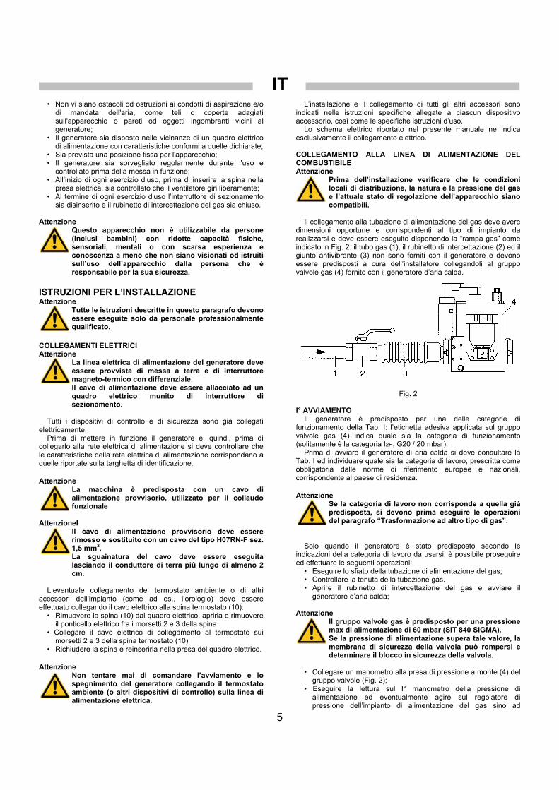
• Non vi siano ostacoli od ostruzioni ai condotti di aspirazione e/o di mandata dell'aria, come teli o coperte adagiati sull'apparecchio o pareti od oggetti ingombranti vicini al generatore;
• Il generatore sia disposto nelle vicinanze di un quadro elettrico di alimentazione con caratteristiche conformi a quelle dichiarate;
• Sia prevista una posizione fissa per l'apparecchio; • Il generatore sia sorvegliato regolarmente durante l'uso e
controllato prima della messa in funzione; • All’inizio di ogni esercizio d’uso, prima di inserire la spina nella
presa elettrica, sia controllato che il ventilatore giri liberamente; • Al termine di ogni esercizio d'uso l’interruttore di sezionamento
sia disinserito e il rubinetto di intercettazione del gas sia chiuso. Attenzione
Questo apparecchio non è utilizzabile da persone (inclusi bambini) con ridotte capacità fisiche, sensoriali, mentali o con scarsa esperienza e conoscenza a meno che non siano visionati od istruiti sull’uso dell’apparecchio dalla persona che è responsabile per la sua sicurezza.
ISTRUZIONI PER L’INSTALLAZIONE Attenzione
Tutte le istruzioni descritte in questo paragrafo devono essere eseguite solo da personale professionalmente qualificato.
COLLEGAMENTI ELETTRICI Attenzione
La linea elettrica di alimentazione del generatore deve essere provvista di messa a terra e di interruttore magneto-termico con differenziale. Il cavo di alimentazione deve essere allacciato ad un quadro elettrico munito di interruttore di sezionamento.
Tutti i dispositivi di controllo e di sicurezza sono già collegati
elettricamente. Prima di mettere in funzione il generatore e, quindi, prima di
collegarlo alla rete elettrica di alimentazione si deve controllare che le caratteristiche della rete elettrica di alimentazione corrispondano a quelle riportate sulla targhetta di identificazione. Attenzione
La macchina è predisposta con un cavo di alimentazione provvisorio, utilizzato per il collaudo funzionale
AttenzioneI
ll cavo di alimentazione provvisorio deve essere rimosso e sostituito con un cavo del tipo H07RN-F sez. 1,5 mm2. La sguainatura del cavo deve essere eseguita lasciando il conduttore di terra più lungo di almeno 2 cm.
L’eventuale collegamento del termostato ambiente o di altri
accessori dell’impianto (come ad es., l’orologio) deve essere effettuato collegando il cavo elettrico alla spina termostato (10):
• Rimuovere la spina (10) dal quadro elettrico, aprirla e rimuovere il ponticello elettrico fra i morsetti 2 e 3 della spina.
• Collegare il cavo elettrico di collegamento al termostato sui morsetti 2 e 3 della spina termostato (10)
• Richiudere la spina e reinserirla nella presa del quadro elettrico. Attenzione
Non tentare mai di comandare l’avviamento e lo spegnimento del generatore collegando il termostato ambiente (o altri dispositivi di controllo) sulla linea di alimentazione elettrica.
L’installazione e il collegamento di tutti gli altri accessori sono indicati nelle istruzioni specifiche allegate a ciascun dispositivo accessorio, così come le specifiche istruzioni d’uso.
Lo schema elettrico riportato nel presente manuale ne indica esclusivamente il collegamento elettrico.
COLLEGAMENTO ALLA LINEA DI ALIMENTAZIONE DEL COMBUSTIBILE Attenzione
Prima dell’installazione verificare che le condizioni locali di distribuzione, la natura e la pressione del gas e l’attuale stato di regolazione dell’apparecchio siano compatibili.
Il collegamento alla tubazione di alimentazione del gas deve avere
dimensioni opportune e corrispondenti al tipo di impianto da realizzarsi e deve essere eseguito disponendo la “rampa gas” come indicato in Fig. 2: il tubo gas (1), il rubinetto di intercettazione (2) ed il giunto antivibrante (3) non sono forniti con il generatore e devono essere predisposti a cura dell’installatore collegandoli al gruppo valvole gas (4) fornito con il generatore d’aria calda.
Fig. 2 I° AVVIAMENTO
Il generatore è predisposto per una delle categorie di funzionamento della Tab. I: l’etichetta adesiva applicata sul gruppo valvole gas (4) indica quale sia la categoria di funzionamento (solitamente è la categoria I2H, G20 / 20 mbar).
Prima di avviare il generatore di aria calda si deve consultare la Tab. I ed individuare quale sia la categoria di lavoro, prescritta come obbligatoria dalle norme di riferimento europee e nazionali, corrispondente al paese di residenza. Attenzione
Se la categoria di lavoro non corrisponde a quella già predisposta, si devono prima eseguire le operazioni del paragrafo “Trasformazione ad altro tipo di gas”.
Solo quando il generatore è stato predisposto secondo le
indicazioni della categoria di lavoro da usarsi, è possibile proseguire ed effettuare le seguenti operazioni:
• Eseguire lo sfiato della tubazione di alimentazione del gas; • Controllare la tenuta della tubazione gas. • Aprire il rubinetto di intercettazione del gas e avviare il
generatore d’aria calda;
Attenzione ll gruppo valvole gas è predisposto per una pressione max di alimentazione di 60 mbar (SIT 840 SIGMA). Se la pressione di alimentazione supera tale valore, la membrana di sicurezza della valvola può rompersi e determinare il blocco in sicurezza della valvola.
• Collegare un manometro alla presa di pressione a monte (4) del
gruppo valvole (Fig. 2); • Eseguire la lettura sul I° manometro della pressione di
alimentazione ed eventualmente agire sul regolatore di pressione dell’impianto di alimentazione del gas sino ad

IT
6
ottenere il corretto valore della pressione di alimentazione indicato in Tab. I;
• Se necessario, è possibile modificare la velocità di apertura della valvola per i modelli equipaggiati con gruppo valvola gas Honeywell o Dungs, agendo, dopo aver rimosso il coperchio di protezione, sulla vite di regolazione: ruotando in senso antiorario la velocità di apertura aumenta, ruotando in senso orario la velocità diminuisce.
TRASFORMAZIONE AD ALTRO TIPO DI GAS
Questa operazione può essere svolta più volte durante la vita operativa della macchina e non solo alla prima accensione. Si deve innanzitutto consultare la Tab. I ed individuare la categoria di riferimento per gas naturale o gas liquido in base al paese di residenza. Per ciascuna categoria sono indicate la pressione di alimentazione, la pressione di lavoro e la predisposizione dell’anello diffusore (3).
Per la trasformazione da un tipo di gas ad un altro si deve: • Se indicato in Tab.I, sostituire l’anello diffusore (3):
• Rimuovere la scocca superiore del generatore; • Svitare e togliere l’elettrodo di ionizzazione (6); • Svitare le viti che fissano la testa di combustione (3) alla
camera di combustione (1). • Togliere le tre viti sul piattello della testa del bruciatore e
sostituire l’anello diffusore bloccandolo poi in modo che l’elettrodo di accensione sia equidistante tra due fori successivi;
• Eseguire la taratura del pressostato gas prediposto sul gruppo valvole gas (Fig. 3)
• Regolare il pressostato gas ad un valore pari a 80% della pressione di alimentazione;
• Regolare il regolatore di pressione del gruppo valvole gas (Fig. 3) alla pressione bruciatore indicata in Tab. I.
• Collegare un manometro alla presa di pressione (1) a monte e un secondo manometro alla presa di pressione a valle (2) del gruppo valvole;
• Avviare il generatore ed eseguire la lettura sul I° manometro della pressione di alimentazione ed eventualmente agire sul regolatore di pressione (3) dell’impianto di alimentazione del gas sino ad ottenere il corretto valore della pressione di alimentazione indicato in Tab. I;
• Eseguire la lettura sul II° manometro della pressione di lavoro ed eventualmente agire con un cacciavite sul regolatore di pressione del gruppo valvole gas (4) per ristabilire la pressione di lavoro al valore indicato in Tab. I
• Applicare sul gruppo valvole gas l’etichetta adesiva con la scritta “PREDISPOSTO PER …” corrispondente al tipo di combustibile e alla categoria prescelta.
ISTRUZIONI PER L’UTILIZZAZIONE AVVIAMENTO
Il generatore può funzionare in modalità “riscaldamento” disponendo l’interruttore (9) in posizione
Per avviare il generatore (Fig. 1): • Assicurarsi che l’interruttore (9) sia sulla posizione “0”; • Alimentare elettricamente il generatore agendo sull’interruttore
di sezionamento posto sul quadro elettrico di alimentazione; • Spostare il commutatore (9) nella posizione ; • Il funzionamento è automatico solo se un termostato o altro
dispositivo di controllo è collegato alla spina termostato (10). • Se dopo tali operazioni il generatore non funziona, si deve
consultare il paragrafo “INCONVENIENTI DI FUNZIONAMENTO, CAUSE E RIMEDI” e scoprire la causa del mancato funzionamento.
ARRESTO
Per arrestare il funzionamento dell’apparecchio si deve agire sul commutatore (9), spostandolo nella posizione “0”, se il funzionamento è manuale, o sul termostato ambiente se il funzionamento è automatico.
Infine si deve chiudere il rubinetto di alimentazione del gas e disinserire l’interruttore di sezionamento.
La fiamma si spegne e il motore ventilatore continua a funzionare secondo la modalità preimpostata (postventilazione temporizzata o postventilazione continua). VENTILAZIONE
Il generatore può funzionare in modalità “ventilazione” disponendo l’interrutore (9) nella posizione : il motore ventilatore si avvia, mentre il bruciatore rimane spento.
TRASPORTO E MOVIMENTAZIONE
Il generatore d’aria calda può essere sollevato e sospeso utilizzando i quattro ganci di ancoraggio predisposti sulla carrozzeria. Attenzione
Prima di spostare l'apparecchio si deve: • Arrestare la macchina secondo le indicazioni del
paragrafo “ARRESTO”; • Disinserire l'alimentazione elettrica estraendo la
spina dalla presa elettrica; • Svitare completamente il raccordo che collega il
tubo per gas al generatore; • Attendere che il generatore si raffreddi.
Attenzione Durante il trasporto e/o il deposito, assicurasi che il gruppo valvola gas e tubi di collegamento gas non sia esposto a possibili urti o danneggiamenti di sorta.
MANUTENZIONE
Per il regolare funzionamento dell’apparecchio è necessario pulire periodicamente i ventilatori, la camera di combustione e il bruciatore. Attenzione
Prima di iniziare qualsiasi operazione di manutenzione si deve: • Arrestare la macchina secondo le indicazioni del
paragrafom “ARRESTO”; • Disinserire l'alimentazione elettrica estraendo la
spina dalla presa elettrica; • Chiudere il rubinetto di intercettazione del gas; • Attendere che il generatore si raffreddi.
Il generatore può essere pulito e lavato con acqua. E’ tuttavia
necessario assicurarsi che: • il cavo di alimentazione elettrica sia stato scollegato e rimosso
dalla presa di alimentazione • tutti i pannelli di accesso siano stati chiusi completamente • non siano utilizzati getti d’acqua a distanza inferiore a 2 m • sia completamente asciugato in ogni sua parte prima di
collegare nuovamente il cavo di alimentazione elettrica Attenzione
Modalità improprie di pulizia del generatore possono causare danni a cose e/o persone.
La pulizia deve essere svolta asportando eventuali corpi estranei
depositati sulle griglie di aspirazione dei ventilatori.

IT
7
Controllare il modello di valvola in dotazione e fare riferimento alla figura corrispondente e alle istruzioni contenute in questo libretto per la regolazione.
SIT 840 SIGMA
1 PRESA DI PRESSIONE IN ENTRATA 2 PRESA DI PRESSIONE IN USCITA 3 REGOLAZIONE STABILIZZATORE DI PRESSIONE
4 GRUPPO VALVOLE 5 PRESSOSTATO GAS
Fig . 3
3 1
2
4
5

IT
8
INCONVENIENTI DI FUNZIONAMENTO, CAUSE E RIMEDI
INCONVENIENTI DI FUNZIONAMENTO
CAUSE RIMEDI
• Verificare le caratteristiche dell’alimentazione elettrica
• Verificare i collegamenti elettrici • Alimentazione elettrica mancante
• Verificare l’integrità del fusibile
• Posizione errata dell’interruttore generale • Selezionare la posizione corretta
• Verificare la posizione del termostato • Funzionamento irregolare del termostato ambiente • Verificare la funzionalità del termostato
• Controllare che la tubazione di alimentazione del gas sia stata spurgata • Intervento del pressostato gas per mancanza di
gas • Controllare la pressione di alimentazione del gas
• Controllare che le griglie di aspirazione e quelle di mandata siano libere
• Controllare che il ventilatore giri liberamente • Intervento del pressostato aria per malfunzionamento del ventilatore
• Controllare il motore elettrico e il condensatore e, se difettosi, sostituirli
• Il generatore non si avvia
• Intervento del pressostato aria per malfunzionamento del pressostato
• Sostituire il pressostato
• L'elettrodo di ionizzazione non rileva presenza fiamma
• Estrarre il sensore di fiamma e pulirlo
• Controllare che le griglie di aspirazione e di mandata non siano ostruite
• Controllare che l'ambiente sia ben aerato
• Controllare che l'aria calda possa uscire liberamente
• Intervento del termostato di sicurezza per sovrariscaldamento della camera di combustione
• Controllare che la portata o la pressione del gas non siano eccessive
• Intervento dell’apparecchiatura di controllo per funzionamento irregolare del bruciatore
• Rivolgersi al Servizio di Assistenza Tecnica
• Apparecchiatura elettronica di controllo difettosa • Controllare l’apparecchiatura e sostituirla, se necessario
• Il generatore si arresta e la lampada spia (8) si illumina con led rosso
• Termostato difettoso • Controllare il termostato e sostituirlo, se necessario
• Intervento del termostato bruciatore • Canali di distribuzione dell'aria eccessivamente lunghi o di piccolo diametro • Il generatore si arresta e riparte e
la lampada spia (8) non si illumina • Intervento del pressostato gas per improvvisi abbassamenti della pressione di alimentazione
• Controllare la pressione di alimentazione del gas
• Corpi estranei depositati sulle pale del ventilatore • Asportare le parti estranee • Rumorosità o vibrazioni del ventilatore • Scarsa circolazione d’aria
• Eliminare ogni possibile ostacolo al passaggio dell’aria
Se con i controlli e i rimedi descritti non è stata individuata la causa del malfunzionamento, si prega di contattare il più vicino centro vendita o assistenza autorizzato.

FR
9
IMPORTANT Avant toute utilisation du générateur, nous vous prions de lire attentivement toutes les instructions pour l'emploi mentionnées ciaprès et d'en suivre scrupuleusement les indications. Le constructeur n'est pas responsable pour les dommages aux personnes et/ou aux biens dus à une utilisation impropre de l'appareil. Ce livret d'utilisation et d'entretien est partie intégrante de l'appareil. Il doit donc être conservé soigneusement et accompagner l'appareil en cas de revente. DESCRIPTION
Les générateurs d'air chaud sont conçus pour le chauffage de locaux non résidentiels, aérés, de moyenne ou grande dimension nécessitant d'un système de chauffage mobile et portatif, selon norme EN 1596:2008, ou pour le chauffage de serres nécessitant d'un chauffage fixe, selon norme EN 12669:2003.
Les générateurs d'air chaud peuvent fonctionner au gaz naturel (G20, G25) ou G.P.L. (butane G30 et propane G31) à différentes pressions d'alimentation en gaz. Le Tab. I indique, pour chaque pays de la Communauté européenne, les gaz pouvant être utilisés et les pressions d'alimentation, la catégorie correspondante (qui indique les deux informations précédentes, à savoir le type de gaz et la pression d'alimentation), le réglage du groupe des soupapes gaz et le type de bague diffuseur (3).
Le générateur est réglé pour l'une des catégories de fonctionnement du Tab. I: l'étiquette adhésive collée sur le groupe soupapes gaz (4) indique la catégorie de fonctionnement de l'appareil.
Pour passer à une autre catégorie, donc à un autre type de gaz, il est nécessaire d'exécuter les opérations expressément prévues au paragraphe "PASSAGE À UN AUTRE TYPE DE GAZ".
Les générateurs d'air chaud sont du type à combustion directe. L'air est réchauffé par l'énergie thermique développée pendant la combustion et il est ensuite envoyé au local à chauffer avec les produits de la combustion: le local devra toujours être correctement aéré afin d'assurer un recyclage d'air suffisant.
Différents dispositifs de sécurité (appareillage électronique de contrôle, thermostat de température excessive L1, pressostat de l'air, pressostat du gaz) interviennent en cas de dysfonctionnement grave.
L'appareillage électronique de contrôle du brûleur intervient lorsque la flamme est irrégulière. Le thermostat de température excessive L1 intervient lorsque la température de la chambre de combustion franchit le seuil de sécurité. Les pressostats de l'air et du gaz, interviennent respectivement si le débit d'air est insuffisant ou si la pression d'alimentation du gaz est trop faible.
Dans chacun de ces cas, le fonctionnement du générateur d'air chaud s'arrête et le témoin du bouton de réarmement (8) s'allume (sauf en cas de faible pression de gaz).
Le fonctionnement ne reprend automatiquement que lorsque l'interruption a été causée par la faible pression du gaz, lors du rétablissement de la conditions normale.
Dans les autres cas, le fonctionnement ne reprend qu'après pression du bouton de réarmement (8) ou (4) selon la description fournie au paragraphe "ANOMALIES DE FONCTIONNEMENT, CAUSES et SOLUTIONS".
Néanmoins, il faut toujours rechercher la cause ayant provoqué l'intervention du dispositif de sécurité et la supprimer avant de remettre le générateur en marche (voir "ANOMALIES DE FONCTIONNEMENT, CAUSES ET SOLUTIONS").
Les générateurs d'air chaud de la série GA/N peuvent être complétés par toute une série d'accessoires:
a) Horloge programmateur ou thermostat d'ambiance ou autre dispositif électromécanique pour la commande aut matique de mise en marche et d'arrêt.
b) Kit pour le contrôle à distance par PC. c) Kit pour le contrôle à distance par tableau (distance maxi 3
mètres), très utile lorsque l'installation au plafond ou dans un local exigu empêche ou limite l'accès au tableau de commande.
d) Kit anti-condensation, indispensable pour les install tions dans les locaux à fort taux d'humidité (serres, élev ges etc.) pour supprimer les risques de défaut d'allumage.
Attention Le témoin du bouton (8) de l'équipement électronique peut s'allumer de différentes manières : • témoin éteint : l'appareil fonctionne correctement. • clignotement rapide : le cycle de démarrage de la
machine est en cours. • clignotement lent : éteint : l'appareil est en veille
(“stand-by”), en attendant une demande de chauffage.
• lumière fixe : l'appareil est en état de “blocage”.
CONSEILS D'ORDRE GÉNÉRAL L'installation, le réglage et l'utilisation du générateur d'air chaud
doivent être accomplis dans le respect de toutes les normes, lois nationales et locales en vigueur concernant l'utilisation de la machine.
Le générateur d'air chaud peut être installé suspendu au plafond à l'aide d'élingues et/ou de chaînes de dimension et longueur appropriées, à fixer aux 4 crochets de suspension. Attention
S'assurer que les élingues et/ou chaînes forment un angle maximum de 5° par rapport à la verticale au plafond.
La distance minimum de toute cloison, sol et/ou plafond doit être
d'au moins 1 mètre et au moins 500 mm du sol. La distance minimum des sorties d'air de tout objet, personne
et/ou animal doit être d'au moins 1,5 mètre. Avant l'installation il est toutefois indispensable de vérifier que lesdits objet, personne et animal sont en mesure de supporter la température maximale de sortie, qui peut être calculée à partir du total de la température ambiante + ∆T @ 1,5 m (comme indiqué sur l'étiquette appliquée sur le générateur d'air chaud).
Il convient de toujours s'assurer que: • Les instructions du présent livret sont scrupuleusement
respectées; • Le générateur n'est pas installé dans des zones à fort risque
d'incendie ou d'explosion; • Aucun matériau inflammable n'est déposé à proximité de
l'appareil (la distance minimum doit être de 3 mètres); • Tout risque de surchauffe des cloisons, plafond ou sol réalisé
dans des matériaux inflammable a été analysé et écarté; • Toutes les mesures aptes à prévenir les incendies ont été
adoptées; • L'aération du local dans lequel est installé le générateur est
garantie et suffit aux besoins du brûleur ; en particulier les limites relatives à la qualité de l'air du local à chauffer doivent respecter les réglementations nationales ou locales en vigueur. A défaut de normes et/ou indications, l'aération du local peut être réalisée en fonction de sa destination, en particulier : • chauffage de locaux non résidentiels, aérés, de moyenne ou
grande dimension selon norme EN 1596: 2008 : • Le volume minimum du local à chauffer doit être déterminé
selon un rapport puissance thermique / volume égal à 100 W/m3. Le volume du local à chauffer ne doit en aucun cas être inférieur à 100 m3.;
• une aération minimum avec l'extérieur de 25 cm2 par kW de puissance thermique doit être garantie, avec un minimum de 250 cm2, correctement réparti entre partie haute et partie basse.
• chauffage de serres selon norme EN 12669:2003.
FR
10
• Il n’existe aucun obstacle ni obstruction aux conduits d'admission et/ou d'évacuation de l'air, tels que bâches ou couvertures posées sur l'appareil ou parois ou objets encombrants placés trop près du générateur;
• Le générateur est installé à proximité d'un coffret électrique d'alimentation possédant des caractéristiques conformes à celles déclarées;
• Une position fixe a été prévue pour l'appareil; • Le générateur est régulièrement surveillé pendant son
fonctionnement et contrôlé avant sa mise en marche; • Au début de chaque période de fonctionnement, aucun obstacle
n'entrave la rotation du ventilateur avant de brancher la fiche dans la prise du réseau;
• À la fin de chaque période de fonctionnement, le sectionneur principal est désactivé et la vanne d'arrêt du gaz est fermée.
Attention
Cet appareil ne doit pas être utilisé par des personnes ou des enfants présentant un handicap physique, sensoriel, mental ou ne possédant pas l'expérience et les connaissances suffisantes à moins qu'ils aient été formés sur son fonctionnement par une personne responsable de la sécurité.
INSTRUCTIONS D'INSTALLATION Attention
Toutes les instructions fournies dans ce paragraphe ne doivent être exécutées que par un personnel qualifié.
BRANCHEMENTS ÉLECTRIQUES Attention
La ligne d'alimentation électrique doit être équipée d'une mise à la terre et d'un disjoncteur magnétothermique avec différentiel. Le câble d'alimentation doit être branché à un coffret électrique muni d'un sectionneur.
Tous les dispositifs de surveillance et de sécurité sont déjà
électriquement connectés. Avant la mise en fonction du générateur donc avant de le brancher
au réseau électrique, il est indispensable de vérifier que les caractéristiques du réseau d'alimentation électrique correspondent à celles reportées sur la plaquette d'identification. Attention
La machine est dotée d'un câble d'alimentation provisoire, utilisé pour le contrôle du fonctionnement.
Attention
Le câble d'alimentation provisoire doit être remplacé par un câble de type H07RN-F d'une section de 1,5 mm2. Retirer la gaine de protection du câble en veillant à ce que la longueur du conducteur de terre soit supérieure de 2 cm à celle des autres.
Le branchement éventuel du thermostat d'ambiance ou d'autres
accessoires de l'installation (ex. horloge) doit être effectué en connectant le câble électrique à la fiche du thermostat (10):
• Débrancher la fiche (10) du coffret électrique, l'ouvrir et retirer le pontet électrique entre les bornes 2 et 3 de la fiche.
• Brancher le câble électrique au thermostat sur les bornes 2 et 3 de la fiche du thermostat (10).
• Refermer la fiche et la rebrancher dans la prise du coffret électrique.
Attention
Ne jamais essayer de mettre en marche ou d'arrêter le générateur en branchant le thermostat d'ambiance (ni aucun autre dispositif de contrôle) sur la ligne d'alimentation électrique.
L'installation et le branchement de tous les autres accessoires sont indiqués dans les instructions spécifiques annexées à chaque dispositif accessoire, à l'instar des instructions d'utilisation spécifiques.
Le schéma électrique fourni dans ce manuel en indique uniquement le branchement électrique. BRANCHEMENT À LA LIGNE D'ALIMENTATION DU COMBUSTIBLE Attention
Avant l'installation, vérifier que les conditions locales de distribution, la nature et la pression du gaz ainsi que le réglage actuel de l'appareil sont compatibles.
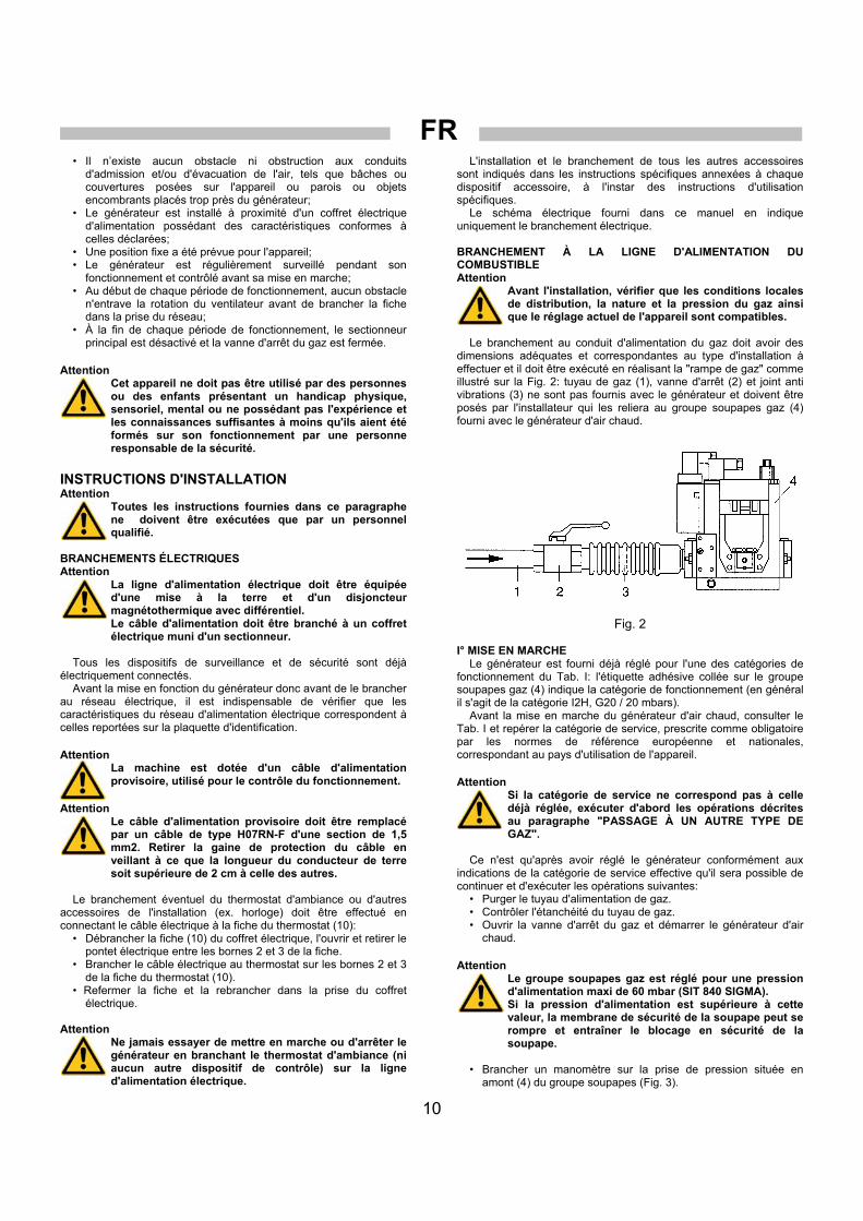
Le branchement au conduit d'alimentation du gaz doit avoir des
dimensions adéquates et correspondantes au type d'installation à effectuer et il doit être exécuté en réalisant la "rampe de gaz" comme illustré sur la Fig. 2: tuyau de gaz (1), vanne d'arrêt (2) et joint anti vibrations (3) ne sont pas fournis avec le générateur et doivent être posés par l'installateur qui les reliera au groupe soupapes gaz (4) fourni avec le générateur d'air chaud.
Fig. 2 I° MISE EN MARCHE
Le générateur est fourni déjà réglé pour l'une des catégories de fonctionnement du Tab. I: l'étiquette adhésive collée sur le groupe soupapes gaz (4) indique la catégorie de fonctionnement (en général il s'agit de la catégorie I2H, G20 / 20 mbars).
Avant la mise en marche du générateur d'air chaud, consulter le Tab. I et repérer la catégorie de service, prescrite comme obligatoire par les normes de référence européenne et nationales, correspondant au pays d'utilisation de l'appareil. Attention
Si la catégorie de service ne correspond pas à celle déjà réglée, exécuter d'abord les opérations décrites au paragraphe "PASSAGE À UN AUTRE TYPE DE GAZ".
Ce n'est qu'après avoir réglé le générateur conformément aux
indications de la catégorie de service effective qu'il sera possible de continuer et d'exécuter les opérations suivantes:
• Purger le tuyau d'alimentation de gaz. • Contrôler l'étanchéité du tuyau de gaz. • Ouvrir la vanne d'arrêt du gaz et démarrer le générateur d'air
chaud. Attention
Le groupe soupapes gaz est réglé pour une pression d'alimentation maxi de 60 mbar (SIT 840 SIGMA). Si la pression d'alimentation est supérieure à cette valeur, la membrane de sécurité de la soupape peut se rompre et entraîner le blocage en sécurité de la soupape.
• Brancher un manomètre sur la prise de pression située en
amont (4) du groupe soupapes (Fig. 3).
FR
11
• Lire la valeur de pression d'alimentation sur le I° manomètre et éventuellement intervenir sur le régulateur de pression du circuit d'alimentation en gaz jusqu'à obtention de la valeur de pression d'alimentation correcte indiquée dans le Tab. I.
• En cas de besoin, (sur les modèles équipés d'un groupe soupapes gaz Honeywell ou Dungs), il est possible de modifier la vitesse d'ouverture de la soupape en agissant sur la vis de réglage, après avoir retiré le couvercle de protection : en tournant vers la gauche (sens antihoraire) on augmente la vitesse d'ouverture, en tournant vers la droite (sens horaire), on diminue la vitesse.
PASSAGE À UN AUTRE TYPE DE GAZ
Cette commutation peut être effectuée plusieurs fois au cours de la vie de la machine et pas uniquement à la première mise en marche. Commencer par contrôler le Tab. I et repérer la catégorie de référence pour gaz naturel ou gaz liquide en fonction du pays d'utilisation de l'appareil. Pour chaque catégorie sont indiquées la pression d'alimentation, la pression de service, et le réglage de la bague diffuseur (3, Fig. 1).
Pour passer d'un type de gaz à un autre, opérer comme suit: • Si indiqué dans le Tab. I, remplacer la bague diffuseur (3);
• Retirer le carter supérieur du générateur; • Dévisser et retirer l'électrode d'ionisation (6); • Dévisser les vis fixant la tête de combustion (3) à la
chambre de combustion (1); • Retirer les trois vis sur le plateau de la tête du brûleur et
remplacer la bague diffuseur en la bloquant de sorte que l'électrode d'allumage se trouve à égale distance entre deux trous consécutifs;
• Procéder au réglage du pressostat de gaz (4) monté sur le groupe soupapes gaz (Fig. 3);
• Régler le pressostat du gaz à une valeur égale à 80% de la pression d'alimentation;
• Régler le régulateur de pression du groupe soupapes gaz (Fig. 3) à la pression du brûleur indiquée dans le Tab. I;
• Brancher un manomètre à la prise de pression en amont (1) et un second manomètre à la prise de pression en aval (2) du groupe soupapes;
• Mettre le générateur en marche et lire la valeur de pression d'alimentation sur le I° manomètre et éventuellement intervenir sur le régulateur de pression (3) du circuit d'alimentation en gaz jusqu'à obtention de la valeur de pression d'alimentation correcte indiquée dans le Tab. I;
• Procéder à la lecture de la pression de service sur le II° manomètre et éventuellement intervenir sur le régulateur de pression du groupe soupapes gaz (4) à l'aide d'un tournevis pour rétablir la pression de service à la valeur indiquée dans le Tab. I;
• Sur le groupe soupapes gaz, coller l'étiquette autocollante portant la mention "PREDISPOSTO PER.../ RÉGLÉ POUR..." correspondant au type de combustible et à la catégorie choisie.
INSTRUCTIONS D'UTILISATION MISE EN MARCHE
Le générateur peut fonctionner en mode “chauffage” en plaçant l'interrupteur (9) sur la position :
Pour mettre le générateur en marche (Fig. 1): • Vérifier que l'interrupteur (9) est bien sur la position "0". • Alimenter l'appareil en agissant sur l'interrupteur général du
coffret électrique d'alimentation. • Placer le commutateur (9) sur la position ; • Le fonctionnement est automatique uniquement si un
thermostat ou un autre dispositif de contrôle est branché à la fiche du thermostat (10).
• Si au terme de ces opérations le générateur ne fonctionne pas, consulter le paragraphe "ANOMALIES DE FONCTIONNEMENT, CAUSES ET SOLUTIONS" et rechercher la raison du dysfonctionnement.
ARRÊT Pour interrompre le fonctionnement de l'appareil, agir sur le
commutateur (9) en le plaçant sur la position "0" en fonctionnement manuel ou sur le thermostat d'ambiance en fonctionnement automatique.
Fermer la vanne d'arrêt du gaz et sectionner l'alimentation. La flamme s'éteint et le moteur du ventilateur continue de
fonctionner selon le mode programmé (post-ventilation temporisée ou post-ventilation continue). VENTILATION
Le générateur peut fonctionner en mode “ventilation” en plaçant l'interrupteur (14) sur la positon : le moteur du ventilateur se met en marche mais le brûleur reste éteint. TRANSPORT ET MANUTENTION
Le générateur d'air chaud peut être soulevé et suspendu à l'aide des quatre crochets d'ancrage aménagés sur son bâti. Attention
Avant tout déplacement: • Arrêter le générateur en suivant les consignes
fournies au paragraphe "ARRÊT"; • Débrancher l'alimentation électrique en retirant la
fiche de la prise; • Dévisser complètement le raccord qui relie le tuyau
du gaz au générateur; • Attendre que le générateur soit froid.
Attention Au cours du transport et/ou du stockage, s'assurer que le groupe soupape gaz et tuyau de liaison gaz ne sont exposé à aucun risque de choc ou d'endommagement.
MAINTENANCE
Afin que l'appareil fonctionne correctement, il est nécessaire de nettoyer régulièrement les ventilateurs, la chambre de combustion et le brûleur. Attention
Avant toute opération d'entretien il est impératif de : • Arrêter le générateur en suivant les consignes
fournies au paragraphe "ARRÊT"; • Débrancher l'alimentation électrique en retirant la
fiche de la prise; • Fermer la vanne d'arrêt du gaz ; • Attendre que le générateur soit froid.
Le générateur peut être nettoyé et lavé à l'eau. Il est alors nécessaire de s'assurer que:
• le câble d'alimentation électrique a été débranché et retiré de la prise d'alimentation
• tous les carters d'accès ont été complètement fermés • le jet d'eau utilisé pour le nettoyage se trouve à une distance
minimum de 2 m • chacun des éléments du générateur est parfaitement sec avant
de rebrancher le câble d'alimentation électrique Attention
Toute modalité impropre de nettoyage du générateur peut causer des dommages aux biens et/ou aux personnes.
Le nettoyage devra être fait en enlevant tout corps étranger éventuel des grilles d'aspiration des ventilateurs

FR
12
Contrôler le modèle de soupape livré avec l'appareil et se reporter à la figure correspondante et aux instructions fournies dans ce livret pour le réglage.
1 PRISE DE PRESSION ENTRÉE 2 PRISE DE PRESSION SORTIE 3 RÉGLAGE STABILISATEUR DE PRESSION
4 GROUPE ÉLECTROVALVE GAZ 5 PRESSOSTAT GAZ
Fig. 3
SIT 840 SIGMA
3 1
2
4
5
FR
13
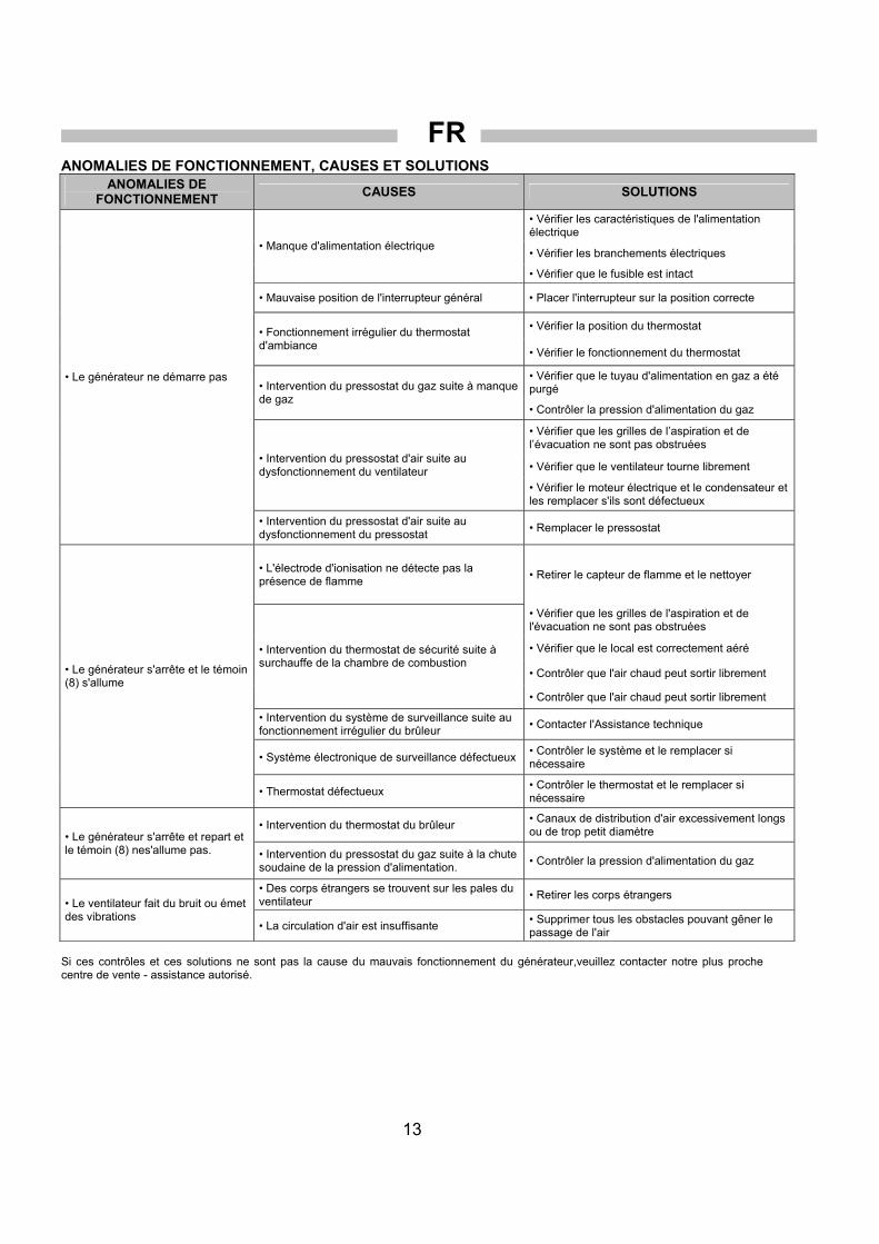
ANOMALIES DE FONCTIONNEMENT, CAUSES ET SOLUTIONS ANOMALIES DE
FONCTIONNEMENT CAUSES SOLUTIONS
• Vérifier les caractéristiques de l'alimentation électrique
• Vérifier les branchements électriques • Manque d'alimentation électrique
• Vérifier que le fusible est intact
• Mauvaise position de l'interrupteur général • Placer l'interrupteur sur la position correcte
• Vérifier la position du thermostat • Fonctionnement irrégulier du thermostat d'ambiance
• Vérifier le fonctionnement du thermostat
• Vérifier que le tuyau d'alimentation en gaz a été purgé • Intervention du pressostat du gaz suite à manque
de gaz • Contrôler la pression d'alimentation du gaz
• Vérifier que les grilles de l’aspiration et de l’évacuation ne sont pas obstruées
• Vérifier que le ventilateur tourne librement • Intervention du pressostat d'air suite au dysfonctionnement du ventilateur
• Vérifier le moteur électrique et le condensateur et les remplacer s'ils sont défectueux
• Le générateur ne démarre pas
• Intervention du pressostat d'air suite au dysfonctionnement du pressostat
• Remplacer le pressostat
• L'électrode d'ionisation ne détecte pas la présence de flamme • Retirer le capteur de flamme et le nettoyer
• Vérifier que les grilles de l'aspiration et de l'évacuation ne sont pas obstruées
• Vérifier que le local est correctement aéré
• Contrôler que l'air chaud peut sortir librement
• Intervention du thermostat de sécurité suite à surchauffe de la chambre de combustion
• Contrôler que l'air chaud peut sortir librement
• Intervention du système de surveillance suite au fonctionnement irrégulier du brûleur
• Contacter l'Assistance technique
• Système électronique de surveillance défectueux • Contrôler le système et le remplacer si nécessaire
• Le générateur s'arrête et le témoin (8) s'allume
• Thermostat défectueux • Contrôler le thermostat et le remplacer si nécessaire
• Intervention du thermostat du brûleur • Canaux de distribution d'air excessivement longs ou de trop petit diamètre • Le générateur s'arrête et repart et
le témoin (8) nes'allume pas. • Intervention du pressostat du gaz suite à la chute soudaine de la pression d'alimentation.
• Contrôler la pression d'alimentation du gaz
• Des corps étrangers se trouvent sur les pales du ventilateur
• Retirer les corps étrangers • Le ventilateur fait du bruit ou émet des vibrations
• La circulation d'air est insuffisante • Supprimer tous les obstacles pouvant gêner le passage de l'air
Si ces contrôles et ces solutions ne sont pas la cause du mauvais fonctionnement du générateur,veuillez contacter notre plus proche centre de vente - assistance autorisé.

DE
14
WICHTIG Vor Benutzung des Warmlufterzeugers ist die Bedienungsanleitung durchzulesen. Die Benutzungsanweisungen sind streng zu beachten. Der Hersteller haftet nicht für Sach- und Personenschäden infolge unsachgemäßen Gebrauchs des Gerätes. Diese Betriebsanleitung ist fester Bestandteil des Gerätes. Sie ist daher sorgfältig aufzubewahren und muss das Gerät im Fall eines Eigentumswechsels begleiten. BESCHREIBUNG
Die Warmlufterzeuger sind für die Industrie-/Gewerbeheizung von mittelgroßen bis großen belüfteten Räumen, für die ein ortsfestes oder mobiles Heizsystem gemäß EN 1596:2008 erforderlich ist, oder für die Gewächshausheizung bestimmt, für die ein ortsfestes Heizsystem gemäß EN 12669:2003 erforderlich ist.
Die Warmlufterzeuger können mit Erdgas (G20, G25) oder mit Flüssiggas (Butan G30 und Propan G31) unter Verwendung unterschiedlicher Gasversorgungsdrücke betrieben werden. In Tab. I sind für jedes EU-Land die verwendbaren Gase und Versorgungsdrücke, die entsprechende Klasse (Angabe der beiden vorausgegangenen Informationen, und zwar Gassorte und Versorgungsdruck), die Einstellung der Gasventileinheit und die Voreinstellung des Düsenrings (3) angegeben.
Der Warmlufterzeuger ist für eine Betriebsklasse aus Tab. I voreingestellt. Diese Betriebsklasse wird vom Klebeetikett auf der Gasventileinheit (4) angegeben.
Für die Umstellung auf eine andere Klasse und folglich auf eine andere Gassorte sind spezifische Maßnahmen erforderlich, die im Abschnitt „UMSTELLUNG AUF EINE ANDERE GASSORTE“ angegeben sind.
Die Warmlufterzeuger arbeiten mit direkter Verbrennung. Die Luft wird unter Ausnutzung der während der Verbrennung erzeugten Wärmeenergie erhitzt und anschließend, gemeinsam mit den Verbrennungsgasen, in den zu beheizenden Raum geleitet. Der Raum muss stets belüftet sein, um einen ausreichenden Luftaustausch zu gewährleisten.
Verschiedene Sicherheitsvorrichtungen (elektronische Kontrollvorrichtung, Sicherheitsthermostat LI, Luftpressostat und Gaspressostat) sprechen bei schweren Betriebsstörungen an.
Die elektronische Kontrollvorrichtung des Brenners greift ein, wenn die Flamme unregelmäßig ist oder cht. Der Sicherheitsthermostat LI spricht an, wenn die Brennkammertemperatur den Sicherheitsgrenzwert überschreitet. Der Luft- und der Gaspressostat sprechen jeweils an, wenn die Luftfördermenge bzw. der Gasversorgungsdruck zu niedrig ist.
In den genannten Fällen wird der Betrieb des Warmlufterzeugers ausgesetzt und es altet sich die Lampe der Reset-Taste (8) ein (außer bei zu niedrigem Gasdruck).
Der Betrieb wird im Fall des niedrigen Gasdrucks wieder aufgenommen, wenn die erforderliche Bedingung erneut eingetreten ist.
In allen anderen Fällen kann der Betrieb erst wieder aufgenommen werden, nachdem die Reset-Taste (8) oder (4) gedrückt wurde, siehe Abschnitt „STÖRUNGEN, URSACHEN UND ABHILFEN”.
Vor erneuter Ingangsetzung des Warmlufterzeugers ist stets die Ursache für die Auslösung der Sicherheitsvorrichtung zu suchen und zu beseitigen (vgl. „STÖRUNGEN, URSACHEN UND ABHILFEN“).
Für die Warmlufterzeuger ist das folgende Zubehör erhältlich: a) Programmieruhr oder Raumthermostat oder eine anderweitige
elektromechanische Vorrichtung für die automatische Start- und Stoppregelung
b) Set für die Fernbedienung über einen PC c) Set für die Fernbedienung über ein externes Bedienpaneel
(Entfernung max. 3 m), empfehlenswert bei behindertem/begrenztem Zugang zur Bedienblende infolge von Deckenmontage oder beengten Platzverhältnissen
d) Set für den Kondensatschutz, unerlässlich in Räumen mit hohem Feuchtigkeitsgehalt (Treibhäuser, Zuchtbetriebe etc.) zur Vermeidung von Startausfällen.
Achtung Die Lampe der Taste (8) der Elektronik kann auf unterschiedliche Weise leuchten: • Ausgeschaltet: ordnungemäßer Betrieb des Geräts; • Schnelles Blinken: das Gerät führt den Startzyklus
aus; • Langsames Blinken: das Gerät befindet sich im
Pausen- oder Bereitschaftszustand in Erwartung der Anforderung des Heizbetriebs;
• Ständig eingeschaltet: das Gerät befindet sich im Zustand “Blockierung”.
ALLGEMEINE HINWEISE
Die Installation, die Einstellung und die Benutzung des Warmlufterzeugers müssen den geltenden nationalen und örtlichen Vorschriften und Gesetzen in Hinsicht auf den Gebrauch des Gerätes entsprechen.
Der Warmlufterzeuger kann, unter Verwendung von Seilen bzw. Ketten entsprechender Größe und Länge, die an den 4 Aufhängehaken zu befestigen sind, in Hängemontage an der Decke angebracht werden.
Achtung
Sicherstellen, dass die Seile bzw. Ketten einen maximalen Winkel von 5° gegen die Deckensenkrechte bilden.
Der Mindestabstand von Wänden, Fußboden bzw. Decke soll
mindestens 1 m und der Bodenabstand soll mindestens 500 mm betragen.
Der Mindestabstand von Gegenständen, Personen bzw. Tieren am Austritt der aufbereiteten Luft soll mindestens 1,5 m betragen. Es ist eine vorherige Prüfung erforderlich, welche die Verträglichkeit der maximalen Temperatur ermittelt. Sie entspricht der Raumtemperatur + ∆T @ 1,5 m (siehe Klebeetikett am Warmlufterzeuger).
Es ist Folgendes sicherzustellen: • Die Anweisungen der vorliegenden Anleitung sind streng zu
beachten; • Der Warmlufterzeuger darf nicht in feuer- oder
explosionsgefährdeten Bereichen aufgestellt werden; • In Gerätenähe dürfen keine feuergefährlichen Materialien
aufbewahrt werden (Abstand mindestens 3 m); • Etwaige Wände, Decken und Fußböden aus entflammbarem
Material dürfen sich nicht zu stark erhitzen; • Es sind die notwendigen Brandschutzmaßnahmen zu ergreifen; • Die Belüftung des Aufstellungsraumes des Warmlufterzeugers
muss stets gewährleistet sein und dem Bedarf des Brenners entsprechen; insbesondere sind die Grenzwerte für die Luftqualität in dem zu beheizenden Raum gemäß der nationalen oder lokalen Vorschriften zu beachten. In Ermangelung von Vorschriften und/oder Angaben kann die Belüftung des Raums gemäß seiner Zweckbestimmung festgelegt werden: • Industrie-/Gewerbeheizung von mittelgroßen bis großen
belüfteten Räumen gemäß EN 1596:2008: • Das Mindestvolumen des Raums muss mit einem
Verhältnis Wärmeleistung/Volumen von 100 W/m3 bestimmt werden. Das Raumvolumen darf keinesfalls weniger als 100 m3 betragen.;
• Es muss eine Lüftungsöffnung mit einer Fläche von mindestens 25 cm2 pro kW Wärmeleistung garantiert sein, wobei die Mindestfläche von 250 cm2 zu gleichen Teilen zwischen oben und unten aufgeteilt sein muss.

DE
15
• Gewächshausheizung gemäß EN 12669:2003. • Die Luftansaug- bzw. Luftförderkanäle dürfen nicht verdeckt
oder verstellt werden z.B. durch abgelegte Planen oder Abdeckungen auf dem Gerät, Wände oder Gegenstände;
• Der Warmlufterzeuger soll in der Nähe einer Schaltanlage aufgestellt werden, deren Stromwerte den deklarierten Anschlusswerten entsprechen;
• Für das Gerät soll ein fester Aufstellungsplatz vorgesehen sein; • Das Gerät soll während des Betriebs regelmäßig überwacht und
vor der Inbetriebsetzung kontrolliert werden; • Bei Beginn jedes Gebrauchs ist vor Anschluss des Netzsteckers
zu überprüfen, dass der Ventilator ungehindert dreht; • Nach dem Betrieb müssen stets der Trennschalter abgeschaltet
und der Gasabsperrhahn geschlossen werden. Achtung
Dieses Gerät darf nicht von Personen (einschließlich Kindern) mit verminderten physischen, sensorischen und geistigen Fähigkeiten oder mit unzureichender Erfahrung und Kenntnis benutzt werden, sofern sie nicht über den Gebrauch des Gerätes von der aufsichtspflichtigen Person eingewiesen und belehrt wurden.
INSTALLATION Achtung
Alle in diesem Abschnitt aufgeführten Arbeiten dürfen nur vom Fachmann ausgeführt werden.
ELEKTRISCHE ANSCHLÜSSE Achtung
Die Stromversorgungsleitung des Warmlufterzeugers muss mit einer Erdung und einem FI-Schutzschalter versehen sein. Der Netzstecker ist an eine Schaltanlage mit Trennschalter anzuschließen.
Sämtliche Kontroll- und Sicherheitseinrichtungen sind bereits
angeschlossen. Vor Inbetriebnahme des Warmlufterzeugers und folglich vor
Anschluss des Gerätes an das Stromversorgungsnetz ist zu kontrollieren, dass die Stromwerte des Stromversorgungsnetzes mit den Angaben auf dem Kennschild übereinstimmen. Achtung
Das Gerät ist mit einem provisorischen Netzkabel für die Funktionsprüfung ausgestattet.
Achtung
Das provisorische Netzkabel ist zu entfernen und gegen ein Kabel Typ H07RN-F Querschn. 1,5 mm2 auszuwechseln. Bei der Abmantelung des Kabels soll der Erdungsleiter mindestens 2 cm länger belassen werden.
Der eventuelle Anschluss des Raumluftthermostats oder anderweitigen Anlagenzubehörs (z.B. Uhr) ist unter Verbindung des Kabels mit dem Thermostatstecker (10) auszuführen: • Den Stecker (10) von der Schaltanlage abziehen, öffnen und
die Brücke zwischen den Klemmen 2 und 3 des Steckers entfernen.
• Das Verbindungskabel zum Thermostat an die Klemmen 2 und 3 des Thermostatsteckers (10) anschließen.
• Den Stecker erneut schließen und an die Steckdose der Schaltanlage anschließen.
Achtung Die Ingangsetzung oder Ausschaltung des Warmlufterzeugers darf niemals durch den Anschluss des Raumluftthermostats (oder anderer Kontrollvorrichtungen) an die Netzleitung geschaltet werden.
ANSCHLUSS AN DIE BRENNSTOFFLEITUNG Achtung
Vor der Installation ist zu überprüfen, dass die örtlichen Verteilungsbedingungen, die Gassorte, der Gasdruck und der aktuelle Regelzustand des Gerätes kompatibel sind.
Der Anschluss an die Gasleitung soll angemessen dimensioniert
sein und dem vorgesehenen Anlagentyp entsprechen. Die „Gasrampe“ soll gemäß Abb. 2 ausgeführt sein: Die Gasleitung (1), der Absperrhahn (2) und die schwingungsdämpfende Kupplung (3) sind nicht im Lieferumfang des Warmlufterzeugers enthalten. Sie sind vom Installateur an die Gasventileinheit (4) anzuschließen, die mit dem Warmlufterzeuger mitgeliefert wird.
Abb. 2
ERSTINBETRIEBNAHME Der Warmlufterzeuger ist für eine Betriebsklasse aus Tab. I
voreingestellt. Das Klebeetikett auf der Gasventileinheit (4) gibt die entsprechende Betriebsklasse an (in der Regel I2H, G20 / 20 mbar).
Vor Ingangsetzung des Warmlufterzeugers ist anhand von Tab. I die Betriebsklasse zu bestimmen, die von den europäischen und nationalen Vorschriften vorgeschrieben ist und dem Nutzerland entspricht. Achtung
Sollte die Betriebsklasse nicht der voreingestellten Klasse entsprechen, sind zuerst die Maßnahmen aus dem Abschnitt „UMSTELLUNG AUF EINE ANDERE GASSORTE“ auszuführen
Erst nach der Einstellung des Warmlufterzeugers auf die
entsprechende Betriebsklasse können die nachstehenden Schritte durchgeführt werden:
• Die Gasversorgungsleitung entlüften. • Die Dichtigkeit der Gasleitung überprüfen. • Den Gasabsperrhahn öffnen und den Warmlufterzeuger starten.
Achtung
Die Gasventileinheit ist für einen Versorgungsdruck von maximal 60 mbar ausgelegt (SIT 840 SIGMA). Wenn der Versorgungsdruck diesen Wert überschreitet, kann die Sicherheitsmembran des Ventils reißen und die Sicherungssperrung des Ventils auslösen.
• Ein Manometer an den zustromseitigen Druckanschluss (4) der Ventileinheit anschließen (Abb. 2);
• Den Druckwert am ersten Versorgungsdruckmanometer ablesen und ggf. den Druckregler der Gasversorgungsanlage verstellen, bis der korrekte Versorgungsdruckwert gemäß Tab. I erzielt ist;

DE
16
• Sofern erforderlich, kann die Öffnungsgeschwindigkeit des Ventils für die Modelle mit Honeywell oder Dungs Gasventileinheit reguliert werden. Hierzu ist nach Entfernung des Schutzdeckels die Stellschraube zu verdrehen, entgegen dem Uhrzeigersinn wird die Öffnungsgeschwindigkeit erhöht, im Uhrzeigersinn wird sie verringert.
UMSTELLUNG AUF EINE ANDERE GASSORTE
Das Gerät kann über seinen gesamten Lebenszyklus und nicht nur bei Erstinbetriebnahme umgestellt werden.
Anhand von Tab. I ist die Betriebsklasse für Erdgas oder Flüssiggas auf der Grundlage des Anwenderlandes zu ermitteln. Für jede Klasse werden der Versorgungsdruck, der Arbeitsdruck und die Voreinstellung des Düsenringes (3, Abb. 1) angegeben.
Gasumstellung: • Sofern in Tab. I angegeben, ist der Düsenring (3)
auszuwechseln: • Das obere Gerätegehäuse entfernen; • Die Ionisationselektrode (6) abschrauben und entfernen; • Die Befestigungsschraube des Brennerkopfes (3) an der
Brennkammer (1) lösen. • Die drei Schrauben am Brennerkopfteller entfernen und den
Düsenring auswechseln. Der Düsenring ist so zu blockieren, dass sich die Zündungselektrode genau in der Mitte zwischen zwei aufeinanderfolgenden Löchern befindet;
• Den Gaspressostat (4) an der Gasventileinheit tarieren (Abb. 3). • Den Gaspressostat auf einen Wert einstellen, der 80% des
Versorgungsdrucks beträgt. • Den Druckregler der Gasventileinheit (Abb. 3) auf den in Tab. I
angegebenen Brennerdruck einstellen. • Ein Manometer an den zustromseitigen Druckanschluss (1)
und ein zweites Manometer an den abstromseitigen Druckanschluss (2) der Ventileinheit anschließen.
• Den Warmlufterzeuger starten. Den Druckwert am ersten Versorgungsdruckmanometer ablesen und ggf. den Druckregler (3) der Gasversorgungsanlage verstellen, bis der korrekte Versorgungsdruckwert gemäß Tab. I erzielt ist.
• Den Druckwert am zweiten Arbeitsdruckmanometer ablesen und ggf. der Druckregler der Gasventileinheit (4) mit einem Schraubendreher verstellen, um den Arbeitsdruck auf den Wert gemäß Tab. I einzustellen.
• An der Gasventileinheit das Klebeetikett mit der Aufschrift „EINGESTELLT FÜR …“ entsprechend der Brennstoffsorte und der gewählten Klasse anbringen.
BENUTZUNG INGANGSETZUNG
Der Warmlufterzeuger kann in der Betriebsart “Heizen” arbeiten. Hierzu ist der Schalter (9) in die Stellung zu schalten.
Starten des Warmlufterzeugers (siehe Abb. 1): • Überprüfen, dass sich der Schalter (9) in der Position „0“
befindet. • Den Warmlufterzeuger über den Trennschalter an der
Schaltanlage mit Strom versorgen. • Schalter (9) in die Position verstellen; • Der Betrieb ist nur dann automatisch, wenn ein Thermostat oder
eine andere Kontrolleinrichtung an den Thermostatstecker (10) angeschlossen ist.
• Wenn das Gerät nach diesen Maßnahmen nicht funktioniert, ist anhand des Abschnitts "STÖRUNGEN, URSACHEN UND ABHILFEN" nach der Ursache für den Funktionsausfall zu suchen.
STILLSETZUNG
Zur Stillsetzung des Gerätes ist im manuellen Betrieb der Schalter (9) in die Position (0) zu schalten bzw. im automatischen Betrieb der Raumluftthermostat zu betätigen.
Danach ist der Gasabsperrhahn zu schließen und der Trennschalter auszuschalten.
Der Brenner wird ausgeschaltet und der Ventilator arbeitet im voreingestellten Betrieb weiter (zeitgeschaltete Nachbelüftung oder kontinuierliche Nachbelüftung).
LÜFTUNG Der Warmlufterzeuger kann in der Betriebsart “ Lüften” arbeiten.
Hierzu ist der Schalter (9) in die Stellung zu schalten. Der Ventilatormotor und der Brennermotor werden gestartet und wenige Sekunden später beginnt der Verbrennungsbetrieb.
TRANSPORT UND HANDHABUNG Der Warmlufterzeuger kann an den vier Ankerhaken am Gehäuse
angehoben werden. Achtung
Vor dem Ortswechsel des Gerätes sind die folgenden Maßnahmen zu ergreifen: • Das Gerät gemäß den Anweisungen aus dem
Abschnitt „STILLSETZUNG“ stoppen. • Die elektrische Versorgung durch Abziehen des
Netzsteckers abschalten. • Das Fitting, das die Gasleitung mit dem Gerät
verbindet, vollständig abschrauben. • Abkühlung des Warmlufterzeugers abwarten.
Achtung
Während des Transports und/oder der Ablage ist darauf zu achten, dass die Gasventileinheit und die Gasanschlussleitungen vor etwaigen Stößen und Beschädigungen geschützt sind.
WARTUNG Für einen einwandfreien Gerätebetrieb sind die Gebläse, die
Brennkammer und der Brenner regelmäßig zu reinigen. Achtung
Vor Wartungsarbeiten sind die folgenden Maßnahmen zu ergreifen: • Das Gerät gemäß den Anweisungen aus dem
Abschnitt „STILLSETZUNG“ stoppen. • Die elektrische Versorgung durch Abziehen des
Netzsteckers abschalten. • Den Gasabsperrhahn schließen. • Abkühlung des Warmlufterzeugers abwarten.
Der Warmlufterzeuger kann mit Wasser gereinigt werden. Bei
Reinigungsarbeiten ist stets Folgendes sicherzustellen: • Das Netzkabel ist vom Netzstecker abgezogen • Alle Zugangspaneele sind vollständig geschlossen • Die Wasserstrahlen sollen einen Abstand von mindestens 2 m
haben • Vor erneutem Anschluss des Netzkabels muss das Gerät
vollkommen trocken sein
Achtung Eine unsachgemäße Reinigung kann zu Sach- und/oder Personenschäden führen.
Bei der Reinigung sind etwaige Fremdkörperablagerungen an den
Luftansauggittern der Gebläse zu entfernen.

DE
17
Das Modell des in der Ausstattung enthaltenen Ventils kontrollieren und für die Regelung die entsprechende Abbildung und die Anweisungen aus diesem Handbuch beachten.
1 DRUCKMESSPUNKT EINLASS 2 DRUCKMESSPUNKT AUSLASS 3 EINSTELLUNG DRUCKSTABILISATOR
4 GASVENTILEINHEIT 5 GASPRESSOSTAT
Abb. 3
SIT 840 SIGMA
3 1
2
4
5
DE
18
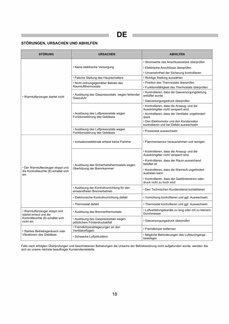
STÖRUNGEN, URSACHEN UND ABHILFEN
STÖRUNG URSACHEN ABHILFEN
• Stromwerte des Anschlussnetzes überprüfen
• Elektrische Anschlüsse überprüfen • Keine elektrische Versorgung
• Unversehrtheit der Sicherung kontrollieren
• Falsche Stellung des Hauptschalters • Richtige Stellung auswählen
• Position des Thermostats überprüfen • Nicht ordnungsgemäßer Betrieb des Raumluftthermostats • Funktionsfähigkeit des Thermostats überprüfen
• Kontrollieren, dass die Gasversorgungsleitung entlüftet wurde • Auslösung des Gaspressostats wegen fehlender
Gaszufuhr • Gasversorgungsdruck überprüfen
• Kontrollieren, dass die Ansaug- und die Ausströmgitter nicht versperrt sind
• Kontrollieren, dass der Ventilator ungehindert dreht
• Auslösung des Luftpressostats wegen Funktionsstörung des Gebläses
• Den Elektromotor und den Kondensator kontrollieren und bei Defekt auswechseln
• Warmlufterzeuger startet nicht
• Auslösung des Luftpressostats wegen Funktionsstörung des Gebläses
• Pressostat auswechseln
• Ionisationselektrode erfasst keine Flamme • Flammensensor herausnehmen und reinigen
• Kontrollieren, dass die Ansaug- und die Ausströmgitter nicht versperrt sind
• Kontrollieren, dass der Raum ausreichend belüftet ist
• Kontrollieren, dass die Warmluft ungehindert austreten kann
• Auslösung des Sicherheitsthermostats wegen Überhitzung der Brennkammer
• Kontrollieren, dass der Gasförderstrom oder-druck nicht zu hoch sind
• Auslösung der Kontrollvorrichtung für den einwandfreien Brennerbetrieb
• Den Technischen Kundendienst kontaktieren
• Elektronische Kontrollvorrichtung defekt • Vorrichtung kontrollieren und ggf. Auswechseln
• Der Warmlufterzeuger stoppt und die Kontrollleuchte (8) schaltet sich ein
• Thermostat defekt • Thermostat kontrollieren und ggf. Auswechseln
• Auslösung des Brennerthermostats • Luftverteilungskanäle zu lang oder mit zu kleinem Durchmesser
• Warmlufterzeuger stoppt und startet erneut und die Kontrollleuchte (8) schaltet sich nicht ein
• Auslösung des Gaspressostats wegen plötzlichem Förderdruckabfall
• Gasversorgungsdruck überprüfen
• Fremdkörperablagerungen an den Ventilatorflügeln
• Fremdkörper entfernen • Starkes Betriebsgeräusch oder Vibrationen des Gebläses
• Schwache Luftzirkulation • Mögliche Behinderungen des Luftdurchgangs beseitigen
Falls nach erfolgten Überprüfungen und beschriebenen Behebungen die Ursache der Betriebsstörung nicht aufgefunden wurde, wenden Sie sich an unsere nächste beauftragte Kundendienststelle.

EN
19
IMPORTANT Before using the space heater, please read carefully all the instructions for use described below and follow the indications scrupulously. The manufacturer cannot be held responsible for damage to persons and/or property caused by improper use of the equipment. This instruction manual is an integral part of the equipment and must therefore be kept carefully and passed on with the unit in the event of a change of ownership. DESCRIPTION
The space heaters are designed for non-domestic heating of medium or large ventilated rooms, which require a mobile and portable heating system in compliance with standard EN 1596:2008, or for heating greenhouses, which require a fixed heating system in compliance with standard EN 12669:2003.
The space heaters can be run on natural gas (G20, G25) or L.P.G. (butane G30 and propane G31) according to different gas supply pressures. Table l shows the useable gases and supply pressures for each country in the European Union, plus the corresponding category (which specifies gas type and supply pressure), the setting of the gas valve unit, and the setting of the diffusion ring (3).
Space heater is set up for one of the operating categories in Tab. I: the adhesive label applied to the gas valve group (4) indicates the operating category.
To convert to a different category and, therefore, to another type of gas, follow the detailed instructions given in the section “CHANGING TYPE OF GAS”.
Space heaters are of the direct combustion type. The air is heated by the thermal energy generated during combustion and is then conveyed to the room to be heated with the products of combustion: the room must in any case be suitably ventilated in order to ensure adequate air circulation.
Various safety devices (electronic control unit, overheating thermostat LI, air pressure switch, gas pressure switch) trip in the event of serious malfunction.
The electronic burner control unit trips if the flame is irregular or goes out. The overheating thermostat LI trips when the temperature of the combustion chamber exceeds the safety limit. The air pressure switch and gas pressure switch trip respectively if the air flow is insufficient or if the gas supply pressure is too low. In each of the cases described above, the space heater stops working and the reset button light (8) comes on (except in the event of low gas pressure). Working resumes automatically only if the cause has been low gas pressure, when the missing supply has been restored.
In other cases working operation can only be resumed by pressing the reset button (8) or (4), as described in the paragraph “FAULTS, CAUSES AND REMEDIES”.
Nonetheless, the cause that triggered the safety device should always be sought and remedied before restarting the heater (see “FAULTS, CAUSES AND REMEDIES”).
Space heaters can be completed with a series of accessories: a) clock timer or room thermostat or a similar
electromechanical device for automatic switching on and off b) kit for remote control from a Personal Computer c) kit for control from the remote panel (max distance 3 m),
useful for ceiling-mounted installations or in restricted situations where access to the control panel is limited
d) anti-condensation kit, indispensable for installations under very humid conditions (greenhouses, battery farming, etc.) to solve the problem of ignition failure.
Warning
The reset button (8) may have different light types: • light off: unit is working normally, flame is
regular. • fast flashing: unit is running on starting cycle. • slow flashing: unit is in stand-by status, waiting
for heating request.
• steady light: lock-out status.
GENERAL ADVICE Installation, setting up and use of the hot air generator must be
effected in accordance with the applicable regulations and laws relating to the use of such equipment.
The space heater can be installed suspended from the ceiling by means of cables and/or chains of suitable size and length to fix to the 4 suspension hooks. Warning
Make sure that the cables and/or chains form a maximum angle of 5° off vertical on the ceiling.
The minimum distance from surrounding walls, floor and/or
ceiling must be at least 1 m and the distance from the floor of at least 500 mm.
The minimum proximity of objects, property, persons and/or animals to be kept in front of the air distribution area must be at least 1,5 m, having checked that they can support the maximum temperature, which can be found by adding the room temperature + ∆T @ 1.5 m (as shown on the identification label affixed to the space heater itself).
Make sure that: • The instructions in this manual are carefully followed; • The generator is not installed in an area where there is a
high risk of fire or explosions; • No flammable materials are stored in the vicinity of the
heater (the minimum distance must be at least 3 m) • A check is made that there is no overheating of walls,
ceilings or floors made of flammable materials • All precautions have been taken to prevent fires; • Ventilation in the room where the heater is installed must be
guaranteed and sufficient for correct burner operation. Specifically, limits concerning air quality in the room to be heated must be complied with, as prescribed by national or local standards and laws. In the absence of standards and/or instructions, room ventilation may be determined according to intended use: • non-domestic heating of medium or large ventilated
rooms, as specified in EN 1596:2008; • minimum room volume must be measured with
thermal power/volume ratio equal to 100 W/m3. Room volume must NEVER be less than 100 m3;
• a minimum ventilation area of 25 cm2 per kW of thermal power must be provided, the minimum being 250 cm2, divided equally between the upper and lower part;
• heating of greenhouses, as specified in EN 12669:2003. • The air suction and/or supply hoses are not blocked in any
way, there are not sheets or covers resting on the machine or walls and bulky objects near the generator;
• The generator is placed near a power switchboard having specifications that conform to those declared;
• The unit is placed in a fixed position; • The heater is regularly monitored during operation and
checked before being started up; • At the beginning of each working period, before plugging it
into the electrical power supply, a check is made that the fan moves freely;

EN
20
• At the end of each working period the main switch is disengaged and the gas stopcock is closed.
Warning
This unit may not be used by persons (including children) with reduced physical, sensorial or mental capacities or with limited experience and familiarity unless they are under supervision or instructed on how to use the equipment by the person responsible for its safety.
INSTALLATION INSTRUCTIONS Warning
All the operations described in this section must only be performed by professional and skilled personnel.
POWER CONNECTIONS Warning
The power line of the generator must be fitted with an earth lead and a residual current circuit breaker. The supply cable must be connected to a switchboard that has an isolation switch.
All the control and safety devices are already electrically
connected. Before switching on the heater, and therefore, before plugging
it into the electrical power supply, a check must be made that the power supply specifications are the same as those stated on the identification plate. Warning
The equipment is fitted with a temporary power cable, used for the working test.
Warning
The temporary power cable must be removed and replaced with a H07RN-F cable having a 1.5 mm2 diameter. The cable must be stripped leaving the earth conductor at least 2 cm longer.
If any room thermostat or other accessories are connected to
the system (such as the timer for example) this must be done by connecting the electrical cable to the thermostat plug (10):
• Take the plug (10) out of the power switchboard, open it and remove the electrical jumper between terminals 2 and 3 of the plug.
• Connect the thermostat electrical cable to terminals 2 and 3 of the thermostat plug (10).
• Close the plug again and plug it back into the power switchboard.
Warning
Never attempt to switch the heater on or off by connecting the room thermostat (or other control devices) to the electrical power line.
Installation and connection of all the other accessories are
given in the specific instructions enclosed with each accessory, like the specific user instructions.
The electrical wiring diagram shown in this manual only shows the electrical connection. FUEL LINE CONNECTIONS Warning
Before installation check that the local gas distribution conditions, the gas type and pressure and the current unit regulation status are compatible.
The gas supply hose connection must be of suitable size and adequate for the type of system to be set up and must be effected by arranging the “gas ramp” as shown in Fig. 2: the gas pipe (1), the cut-off valve (2) and the antivibration coupling (3) are not supplied with the heater and so must be provided by the installer connecting them to the al gas valve group (4) supplied with the space heater.
Fig. 2 1st START UP
The heater is set up for one of the operating categories in Tab. I: the adhesive label applied on the gas valve group (4) indicates the appliance category (usually category I2H, G20 / 20 mbar).
Before starting the generator it is necessary to consult the Tab. I to establish the original appliance category, fixed compulsory from the referring European and national rules, relating to the country of residence. Warning
If the appliance category is not the one the unit is set up for, follow the detailed instructions in the section “CHANGING TYPE OF GAS”.
Only when the heater has been prearranged according to its
proper appliance category will it be possible to carry out the following operations:
• Leak away some gas from the feed pipe; • Check that the gas pipe has no leaks. • Open the gas stopcock and start the space heater;
Warning The gas valve group is set up for a maximum supply pressure of 60 mbar (SIT 840 SIGMA). If the supply pressure is greater than this value, the valve safety membrane could break and cause the valve safety stop to be triggered.
• Connect a gauge to the upstream pressure intake (4) of the
valve group (Fig. 2); • Read the supply pressure off the 1st gauge and if necessary
adjust the gas supply system pressure regulator until the correct supply pressure shown in Tab. I is reached;
• If necessary, the valve opening speed can be varied for models fitted with a Honeywell or Dungs gas valve group, by removing the protective cover and then turning the screw adjuster: turning counter clockwise increases the opening speed while turning it clockwise decreases the speed.
CHANGING TYPE OF GAS
This operation may be carried out several times during the working life of the heater and not only at initial start-up.
First of all refer to Tab. I to identify the reference category for natural gas or liquid gas according to the country of residence. For each category the supply pressure, the working pressure and the arrangement of the diffusion ring (3) are stated.
To convert from one type of gas to another proceed as follows: • If stated in Tab.I, change the diffusion ring (3 Fig. 1):
• Remove the upper body of the heater;

EN
21
• Unscrew and remove the ionisation electrode (6); • Undo the screws that secure the combustion head (3)
to the combustion chamber (1); • Remove the three screws on the burner head plate
and change the diffusion ring securing it in such a way that the ignition electrode is equidistant between the two subsequent holes;
• Calibrate the gas pressure switch (4) on the gas valve group (Fig.3):
• Regulate the gas pressure switch to a value equal to 80% the supply pressure;
• Regulate the pressure regulator for the gas valve group (Fig.3); to the burner pressure stated in Tab. I.:
• Connect a gauge to the pressure intake (1) upstream and a second gauge to the pressure intake downstream (2) of the valve group;
• Start the heater and take the reading off the 1st supply pressure gauge and if necessary adjust the pressure regulator (3) for the gas supply system until the correct supply pressure shown in Tab. I is reached;
• Take a reading off the 2nd working pressure gauge and if necessary use a screwdriver to adjust the pressure of the gas valve group (4) to restore the working pressure shown in Tab. I
• Apply the adhesive label with the words “SET UP FOR …” corresponding to the type of fuel and the category chosen on the gas valve group.
OPERATING INSTRUCTIONS START-UP
The heater works in “heating” mode, turning the switch (9) to . To start the space heater (Fig. 1): • Make sure the switch (9) is set to “0”; • Switch on power to the heater by means of the isolation
switch on the power switchboard; • Move the switch (9) to position ; • Operation will only be automatic if a thermostat or another
control device is connected to the thermostat plug (10). • If after these operations, the generator does not work, refer
to the “FAULTS, CAUSES AND REMEDIES” section and find the cause.
STOP To stop operation turn the switch (9) to “0” if operation is
manual, or to room thermostat if operation is automatic. Lastly, close the gas supply stopcock and turn off the isolation
switch. The flame goes out and the fan motor will continue to run until
the combustion chamber has cooled down completely. The flame goes out and the fan motor continues to work
according to the preset mode (timed post-ventilation or continuous post-ventilation).
VENTILATION The heater can work in “ventilation” mode turning the switch
(14) to : the fan motor starts, while the burner is off.
TRANSPORT AND HANDLING The space heater can be lifted up and suspended using the
four anchor hooks provided in the casing. Warning
Before moving the unit: • Stop the machine as indicated in the “STOP”
paragraph; • Disengage the power supply by removing the
plug from the power socket; • Fully unscrew the fitting that connects the gas
pipe to the heater; • Wait until the heater has cooled down.
Warning During transportation and/or storage, make sure the gas valve group and gas connection pipes are not knocked or damaged in any way.
MAINTENANCE
For proper working efficiency the fans, the combustion chamber and the burner must be cleaned periodically. Warning
Before performing any maintenance operations: • Stop the machine as indicated in the “STOP”
paragraph; • Disengage the power supply by removing the
plug from the power socket; • Close the gas supply stopcock; • Wait until the heater has cooled down.
The heater can be cleaned and washed with water. It is
however necessary to ensure that: • the power lead is disconnected and unplugged from the power supply socket • all access panels have been completely closed • no water jets are used at a distance of less than 2 m • all parts of it are completely dry before plugging in the power lead again.
Warning
Cleaning the heater by the wrong procedures can cause damage to things and/or persons.
Cleaning must be carried out by removing any foreign bodies
from the fan suction grills.
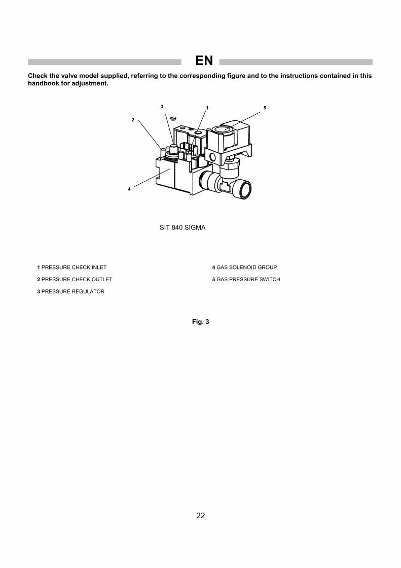
EN
22
Check the valve model supplied, referring to the corresponding figure and to the instructions contained in this handbook for adjustment.
1 PRESSURE CHECK INLET 2 PRESSURE CHECK OUTLET 3 PRESSURE REGULATOR
4 GAS SOLENOID GROUP 5 GAS PRESSURE SWITCH
Fig. 3
SIT 840 SIGMA
3 1
2
4
5

EN
23
FAULTS, CAUSES AND REMEDIES
FAULTS CAUSES REMEDIES
• Check power specifications
• Check power connections • No power supply
• Check fuse
• Main switch in wrong position • Select correct position
• Check thermostat position • Faulty operation of room thermostat
• Check thermostat operation
• Check that the gas supply hose has been bled • Gas pressure switch tripped due to no gas
• Check the gas supply pressure
• Check that the suction and the flow grills are unobstructed
• Check that the fan is running freely • Air pressure switch tripped due to fan malfunction
• Check the electric motor and the condenser and, if faulty, replace them
• The heater fails to start
• Air pressure switch tripped due to pressure switch malfunction
• Replace the pressure switch
• The ionisation electrode does not detect a flame • Remove the flame sensor and clean it
• Check that the suction and the flow grills are unobstructed
• Check that the room is well ventilated
• Check that the hot air can escape freely • Safety thermostat tripped due to the combustion chamber overheating
• Check that the gas flow or pressure are not excessive
• Control unit tripped due to irregular burner operation
• Contact Service Assistance
• Faulty electronic control unit • Check the unit and if necessary replace it
• The heater stops and the warning light (8) comes on
• Faulty thermostat • Check the thermostat and if necessary replace it
• Burner thermostat tripped • Air distribution ducts too long or with insufficient diameter • the heater stops and then starts
again but the warning light (8) does not come on • Gas pressure switch tripped due to sudden drop
in gas supply pressure • Check the gas supply pressure
• Foreign bodies on fan blades • Remove foreign bodies
• Fan noise or vibrations • Little air circulation • Eliminate all possible obstacles to proper air flow
If heater still not working properly, please revert to nearest authorized dealer.

ES
24
IMPORTANTE Antes de usar el generador, se recomienda leer con atención todas las instrucciones de uso que se presentan a
continuación y seguir escrupulosamente sus indicaciones. El fabricante declina toda responsabilidad por lesiones a las personas y daños a las cosas provocados por un uso inadecuado del aparato. El presente manual de uso y
mantenimiento constituye parte integrante del aparato por lo que debe conservarse con cuidado y debe acompañar al aparato en caso de traspaso de propiedad.
DESCRIPCIÓN
Los generadores de aire caliente pueden estar destinados a la calefacción de locales de uso no doméstico ventilados de medianas o grandes dimensiones, para los que se requiere un sistema de calefacción móvil y portátil de acuerdo con la norma EN 1596:2008, o bien a la calefacción de invernaderos, para los que se requiere un sistema de calefacción fijo de acuerdo con la norma EN 12669:2003.
Los generadores de aire caliente pueden funcionar con gas natural (G20, G25) o g.l.p. (butano G30 y propano G31), según las diferentes presiones de alimentación del gas. En la Tabla I se señalan, para cada país de la Unión Europea, cuáles son los gases utilizables y las presiones de alimentación, la categoría correspondiente (que indica las dos informaciones anteriores, esto es, el tipo de gas y la presión de alimentación), la regulación del grupo válvulas de gas y la predisposición del anillo difusor (3).
El generador está predispuesto para una de las categorías de funcionamiento de la Tabla I: la etiqueta adhesiva aplicada en el grupo válvulas de gas (4) indica cuál es la categoría de funcionamiento. Para la trasformación a otra categoría y, por lo tanto, a otro tipo de gas, deben efectuarse las operaciones específicas indicadas en el apartado “TRANSFORMACIÓN A OTRO TIPO DE GAS”.
Los generadores de aire caliente son del tipo de combustión directa. El aire se calienta utilizando la energía térmica desarrollada durante la combustión y luego es enviado al ambiente a calentar junto con los produco de la combustión: el ambiente deberá estar adecuadamente ventilado a fin de garantizar un recambio de aire suficiente.
En caso de producirse un mal funcionamiento grave, intervienen diferentes dispositivos de seguridad (equipo electrónico de control, termostato de sobretemperatura LI, presostato del aire, presostato del gas).
El equipo electrónico de control del quemador interviene cuando la llama es irregular o se apaga. El termostato de sobretemperatura. LI interviene cuando la temperatura de la cámara de combustión supera el valor límite de seguridad. El presostato del aire y el del gas intervienen respectivamente si el caudal del aire es insuficiente o si la presión de alimentación del gas es demasiado baja. En cada uno de los casos descritos el generador de aire caliente deja de funcionar y la lámpara del pulsador de restablecimiento (8) se enciende (excepto en el caso de baja presión del gas).
El funcionamiento se reanuda automáticamente sólo si la causa ha sido baja presión del gas, al restablecerse la condición faltante. En los otros casos el funcionamiento sólo puede reanudarse presionando el pulsador de restablecimiento (8) o (4), según lo descrito en el apartado “INCONVENIENTES DE FUNCIONAMIENTO, CAUSAS Y SOLUCIONES”.
En cualquier caso, antes de reactivar el generador se deberá localizar la causa que ha provocado la intervención del dispositivo de seguridad y eliminarla (ver “INCONVENIENTES DE FUNCIONAMIENTO, CAUSAS Y SOLUCIONES”).
Los generadores de aire caliente pueden ser equipados con una serie de accesorios:
a) reloj programador o termostato ambiente u otro dispositivo electromecánico para el mando automático de arranque y apagado;
b) kit para el control remoto desde ordenador personal;
c) kit para el control remoto desde panel (distancia máx. 3 m), útil cuando la instalación de techo o en ambientes reducidos impide o limita el acceso al panel de mando;
d) kit anticondensación, indispensable en las aplicaciones en ambientes de elevada humedad (invernaderos, criaderos, etc.) para resolver el problema de fallos de encendido.
Atención
El pulsador (8) del equipo electrónico puede presentar diversos estados de iluminación: • luz apagada: la máquina está funcionando
regularmente; • parpadeo rápido: la máquina está realizando el
ciclo de arranque; • parpadeo lento: la máquina está en pausa o
“stand-by”, en espera de la petición de calefacción;
• luz fija: la máquina se encuentra en estado de “bloqueo”.
RECOMENDACIONES GENERALES
La instalación, la regulación y el uso del generador de aire caliente deben respetar las reglas y las leyes nacionales y locales vigentes relativas a la utilización del aparato.
El generador de aire caliente puede instalarse suspendido del techo mediante cables y/o cadenas, de dimensiones y longitud adecuadas, fijándolos a los 4 ganchos de suspensión. Atención
Verificar que los cables y/o cadenas formen un ángulo máximo de 5° con la perpendicular al techo.
La distancia mínima respecto de las paredes circundantes, del
piso y/o del techo debe ser de al menos 1 m y la altura desde el piso de al menos 500 mm.
La distancia mínima que han de mantener personas, objetos y/o animales respecto a la salida del aire distribuido debe ser de al menos 1,5 m, previa verificación de que puedan soportar la temperatura máxima, que se calcula sumando la temperatura ambiente + ∆T @ 1,5 m (tal como se indica en la etiqueta de datos aplicada al generador de aire caliente mismo).
Asegurarse de que: • Se sigan estrictamente las instrucciones contenidas en el
presente manual. • No se instale el generador en las áreas de mayor riesgo de
incendio o de explosión. • No se depositen materiales fácilmente inflamables en
proximidad del aparato (la distancia mínima debe ser de 3 m);
• No se produzcan recalentamientos de paredes, techos o pisos realizados con materiales inflamables;
• Hayan sido adoptadas las medidas necesarias para prevenir incendios;
• Esté garantizada la ventilación del local en el que se halla el generador y que dicha ventilación sea suficiente para las necesidades del quemador; en particular deben respetarse los límites relativos a la calidad del aire en el ambiente a calentar establecidos por las normas y leyes nacionales o locales sobre la materia. En ausencia de normas y/o

ES
25
indicaciones, la ventilación del local puede establecerse en función del destino de uso, en particular: • calefacción de locales de uso no doméstico ventilados de
medianas o grandes dimensiones tal como se indica en EN 1596:2008: • el volumen mínimo de la habitación se calcula
mediante la relación entre potencia térmica y volumen, que debe ser igual a 100 W/m3. En ningún caso el volumen de la habitación debe ser inferior a 100 m3;
• debe estar prevista un área mínima de ventilación hacia el exterior de 25 cm2 por kW de potencia térmica, siendo el mínimo de 250 cm2, equitativamente dividida entre la parte superior y la parte inferior.
• calefacción de invernaderos tal como se indica en EN 12669:2003.
• No existan obstáculos ni obstrucciones para los conductos de aspiración y/o de impulsión del aire, tales como lonas o cubiertas colocadas sobre el aparato o paredes u objetos voluminosos situados cerca del generador;
• El generador esté colocado cerca de un cuadro eléctrico de alimentación cuyas características sean conformes con las declaradas;
• Esté prevista una posición fija para el aparato; • El generador sea controlado antes de ser puesto en
funcionamiento y sea vigilado regularmente durante el uso; • Al inicio de cada utilización y antes de introducir el enchufe
en la toma eléctrica, el ventilador gire libremente; • El interruptor de seccionamiento sea desenchufado y la
llave de interceptación del gas sea cerrada al finalizar cada utilización.
Atención
Este aparato no puede ser utilizado por personas (niños incluidos) con capacidades físicas, sensoriales y/o mentales reducidas o que carezcan de suficiente experiencia y conocimiento, a menos que sean supervisadas o capacitadas sobre el uso del aparato por la persona responsabile de su seguridad.
INSTRUCCIONES PARA LA INSTALACIÓN Atención
Todas las instrucciones del presente apartado deben ser ejecutadas únicamente por personal professionalmente cualificado.
CONEXIONES ELÉCTRICAS Atención
La línea eléctrica de alimentación del generador debe estar equipada con puesta a tierra e interruptor magnetotérmico con diferencial. El cable de alimentación debe ser conectado a un cuadro eléctrico provisto de interruptor de seccionamiento.
Todos los dispositivos de control y de seguridad ya están
conectados eléctricamente. Antes de poner en funcionamiento el generador y, por lo tanto,
antes de conectarlo a la red eléctrica de alimentación, se debe controlar que las características de la red eléctrica de alimentación se correspondan con las indicadas en la placa de identificación. Atención
La máquina dispone de un cable de alimentación provisorio, utilizado para la prueba de funcionamiento.
Atención
El cable de alimentación provisorio debe sustituirse con un cable del tipo H07RN-F de 1,5
mm² de sección. El desenvainado del cable debe efectuarse dejando el conductor de tierra al menos 2 cm más largo.
Para efectuar la conexión del termostato ambiente u otros accesorios del equipo (como por ejemplo el reloj) se deberá conectar el cable eléctrico al enchufe termostato (10):
• Quitar el enchufe (10) del cuadro eléctrico, abrirlo y quitar el puente eléctrico entre los bornes 2 y 3 del enchufe; • Conectar el cable eléctrico de conexión al termostato a los bornes 2 y 3 del enchufe del termostato (10); • Cerrar el enchufe e insertarlo en la toma del cuadro eléctrico.
Atención
No intentar nunca poner en marcha o apagar el generador conectando el termostato ambiente (u otros dispositivos de control) a la línea de alimentación eléctrica.
La instalación y la conexión de todos los otros accesorios se
indican en las instrucciones específicas que se adjuntan a cada dispositivo accesorio, así como las específicas instrucciones de uso.
El esquema eléctrico incluido en el presente manual indica exclusivamente su conexión eléctrica. CONEXIÓN A LA LÍNEA DE ALIMENTACIÓN DEL COMBUSTIBLE Atención
Antes de efectuar la instalación se deberá verificar que las condiciones locales de distribución, el tipo y la presión del gas sean compatibles con el estado de regulación del aparato.
ILa conexión a la tubería de alimentación del gas debe ser de
dimensiones adecuadas y correspondientes al tipo de instalación que se ha de realizar y debe efectuarse disponiendo la “rampa de gas” de la manera indicada en Fig. 2: el tubo de gas (1), la llave de interceptación (2) y la junta anti-vibraciones (3) no se suministran junto con el generador y deberán ser predispuestos por el instalador, que los conectará al grupo válvulas de gas (4) suministrado con el generador de aire caliente.
Fig. 2
PRIMERA PUESTA EN MARCHA
El generador está predispuesto para una de las categorías de funcionamiento indicadas en la Tabla I: la etiqueta adhesiva aplicada en el grupo válvulas de gas (4) indica cuál es la categoría de funcionamiento (generalmente es la categoría I2H, G20 / 20 mbares).
Antes de poner en marcha el generador de aire caliente se debe consultar la Tabla I para identificar cuál es la categoría de trabajo, prescrita como obligatoria por las normas de referencia europeas y nacionales, correspondiente al país de residencia.

ES
26
Atención Si la categoría de trabajo no se corresponde con la que se encuentra predispuesta, deberán efectuarse ante todo las operaciones indicadas en el apartado “TRANSFORMACIÓN A OTRO TIPO DE GAS”.
Sólo una vez que el generador haya sido predispuesto según
las indicaciones de la categoría de trabajo a utilizar será posible proseguir y efectuar las siguientes operaciones:
• Purgar la tubería de alimentación del gas; • Controlar la estanqueidad de la tubería de gas; • Abrir la llave de interceptación del gas y poner en marcha el
generador de aire caliente; Atención
IEl grupo válvulas de gas está predispuesto para una presión máx. de alimentación de 60 mbares (SIT 840 SIGMA). Si la presión de alimentación supera dicho valor, la membrana de seguridad de la válvula puede romperse y provocar el bloqueo de seguridad de la válvula.
• Conectar un manómetro a la toma de presión línea arriba (4) del grupo válvulas (Fig. 2);
• Leer la presión de alimentación en el Ier. manómetro y, de ser necesario, intervenir en el regulador de presión de la instalación de alimentación del gas hasta obtener el valor correcto de presión de alimentación indicado en Tabla I;
• De ser necesario, es posible modificar la velocidad de apertura de la válvula en los modelos equipados con grupo válvula de gas Honeywell o Dungs mediante el tornillo de regulación, después de haber quitado la tapa de protección. Girando el tornillo en sentido antihorario la velocidad de apertura aumenta, rientra que girándolo en sentido horario la velocidad disminuye.
TRANSFORMACIÓN A OTRO TIPO DE GAS
Esta operación puede efectuarse varias veces durante la vida operativa del aparato y no sólo en la primera puesta en funcionamiento.
Ante todo es necesario consultar la Tabla I e identificar la categoría de referencia para gas natural o gas líquido para el país de residencia. Para cada categoría se indican la presión de alimentación, la presión de trabajo y la predisposición del anillo difusor (3, Fig. 1). Para la trasformación de uno a otro tipo de gas se debe deberán efectuarse las intervenciones que se ilustran a continuación.
• Si está indicado en Tabla I, sustituir el anillo difusor (3): • Desmontar el bastidor superior del generador; • Aflojar y quitar el electrodo de ionización (6); • Aflojar los tornillos que fijan la cabeza de combustión (3)
a la cámara de combustión (1); • Quitar los tres tornillos presentes en el platillo de la
cabeza del quemador, sustituir el anillo difusor y bloquearlo de forma que el electrodo de encendido esté equidistante entre dos agujeros sucesivos.
• Efectuar la calibración del presostato gas (4) predispuesto en el grupo válvulas de gas (Fig. 4): • Regular el presostato gas a un valor igual a 80% de la
presión de alimentación. • Regular el regulador de presión del grupo válvulas de gas
(Fig. 3); a la presión del quemador indicada en Tabla I: • Conectar un manómetro a la toma de presión (1) línea
arriba y un segundo manómetro a la toma de presión línea abajo (2) del grupo válvulas;
• Poner en marcha el generador, leer la presión de alimentación en el Ier. manómetro y, de ser necesario, intervenir en el regulador de presión (3) de la instalación
de alimentación del gas hasta obtener el valor correcto de presión de alimentación indicado en Tabla I;
• Leer la presión de trabajo en el II° manómetro y, de ser necesario, intervenir con un destornillador en el regulador de presión del grupo válvulas de gas (4) para restablecer el valor de presión de trabajo indicado en Tabla I.
• Aplicar en el grupo válvulas de gas la etiqueta adhesiva con la leyenda “PREDISPUESTO PARA …” correspondiente al tipo de combustible y a la categoría escogida.
INSTRUCCIONES DE USO PUESTA EN MARCHA
Para hacer funcionar el generador en modalidad “calefacción”, situar el interruptor en posición .
Para poner en marcha el generador (Fig. 1): • Asegurarse de que el conmutador (9) esté en posición “0”; • Alimentar eléctricamente el generador mediante el
interruptor de seccionamiento situado en el cuadro eléctrico de alimentación;
• Poner el conmutador (9) en la posición ; • El funcionamiento es automático sólo si un termostato u
otro dispositivo de control está conectado al enchufe termostato (10);
• Si después de efectuar dichas operaciones el generador no funciona, se debe consultar el apartado “INCONVENIENTES DE FUNCIONAMIENTO, CAUSAS Y SOLUCIONES” para descubrir la causa de la falta de funcionamiento.
PARADA
Para detener el aparato se debe intervenir en el conmutador (9), poniéndolo en posición “0”, en caso de funcionamiento en manual, o en el termostato ambiente en caso de funcionamiento en automático.
Por último se debe cerrar la llave de alimentación del gas y desconectar el interruptor de seccionamiento.
La llama se apaga y el motor ventilador continúa funzionando según la modalidad programada (post ventilación temporizada o post ventilación continua). VENTILACIÓN
Para hacer funcionar el generador en modalidad “ventilación”, situar el interruptor (9) en posición : el motor ventilador arranca, rientra que el quemador permanece apagado. TRANSPORTE Y DESPLAZAMIENTO
El generador de aire caliente puede ser levantado y suspendido utilizando los cuatro ganchos de anclaje predispuestos en la carrocería. Atención
Antes de desplazar el aparato es necesario: • Detener el aparato según las indicaciones del
apartado “PARADA”. • Desconectar la alimentación eléctrica
extrayendo el enchufe de la toma eléctrica. • Aflojar completamente el racor que conecta el
tubo de gas al generador. • Esperar a que el generador se enfríe.
Atención Durante el transporte y/o el depósito, asegurarse de que el grupo válvula de gas y tubos de conexión gas no esté expuesto a posibles golpes ni a daños de ningún tipo.
MANTENIMIENTO
Para el regular funcionamiento del aparato es necesario limpiar periódicamente los ventiladores, la cámara de combustión y el quemador.

ES
27
Atención Antes de iniciar cualquier operación de mantenimiento se debe: • Detener el aparato según las indicaciones del
apartado “PARADA”. • Desconectar la alimentación eléctrica
extrayendo el enchufe de la toma eléctrica. • Cerrar la llave de interceptación del gas. • Esperar a que el generador se enfríe.
El generador puede limpiarse y lavarse con agua. Sin embargo es necesario verificar que:
• el cable de alimentación eléctrica haya sido desconectado y desenchufado de la toma de alimentación;
• todos los paneles de acceso hayan sido completamente cerrados;
• no se hayan utilizado chorros de agua desde una distancia inferior a 2 m;
• esté completamente seco, en todas sus partes, antes de volver a conectar el cable de alimentación eléctrica.
Atención
Limpiar el generador de modo inapropiado puede causar daños a las personas y/o a las cosas.
La limpieza debe efectuarse eliminando todo cuerpo extraño que se haya depositado en las rejillas de aspiración de los ventiladores.
Controlar el modelo de la válvula suministrada y efectuar la regulación tomando como referencia la figura correspondiente y las instrucciones del presente manual.
1 PRESSURE CHECK INLET 2 PRESSURE CHECK OUTLET 3 PRESSURE REGULATOR
4 GAS SOLENOID GROUP 5 GAS PRESSURE SWITCH
Fig. 4
SIT 840 SIGMA
3 1
2
4
5

ES
28
INCONVENIENTES DE FUNCIONAMIENTO, CAUSAS Y SOLUCIONES
INCONVENIENTES DE FUNCIONAMIENTO
CAUSAS SOLUCIONES
• Verificar las características de la alimentación eléctrica
• Controlar las conexiones eléctricas • Ausencia de alimentación eléctrica
• Comprobar la integridad del fusible
• Posición errónea del interruptor general • Seleccionar la posición correcta
• Verificar la posición del termostato • Funcionamiento irregular del termostato ambiente • Verificar la funcionalidad del termostato
• Controlar que la tubería de alimentación del gas haya sido purgada • Intervención del presostato por falta de gas
• Controlar la presión de alimentación del gas
• Controlar que las rejillas de aspiración y de impulsión estén libres
• Controlar que el ventilador gire libremente • Intervención del presostato aire por mal funcionamiento del ventilador
• Controlar el motor eléctrico y el condensador y sustituirlos si están averiados
• El generador no se pone en marcha
• Intervención del presostato aire por mal funcionamiento del presostato
• Sustituir el presostato
• El electrodo de ionización no detecta la presencia de llamas • Extraer el sensor de llama y limpiarlo
• Controlar que las rejillas de aspiración y de impulsión no estén obstruidas
• Controlar que el ambiente esté adecuadamente ventilado
• Controlar que el aire caliente pueda salir libremente
• Intervención del termostato de seguridad por sobrecalentamiento de la cámara de combustión
• Controlar que el caudal y la presión de los gases no sean excesivos
• Intervención del equipo de control por funcionamiento irregular del quemador
• Dirigirse al Servicio de Asistencia Técnica
• Avería en el equipo electrónico de control • Controlar el equipo y sustituirlo en caso de ser necesario
• El generador se detiene y el testigo luminoso (8) se enciende
• Avería en el termostato • Controlar el termostato y sustituirlo en caso de ser necesario
• Intervención del termostato quemador • Canales de distribución del aire excesivamente largos o de pequeño diámetro • El generador se detiene y vuelve
a arrancar y la lámpara testigo (8) no se enciende • Intervención del presostato gas por repentino
descenso • de la presión de alimentación • Controlar la presión de alimentación del gas
• Cuerpos extraños depositados en las palas del ventilador
• Quitar los cuerpos extraños • Ruidosidad o vibraciones del ventilador
• Escasa circulación de aire • Eliminar cualquier posible obstáculo al paso del aire
Si con los controles y solucciones describidos no se individua la causa del problema de funcionamiento dirigirse al más cercano centro venta y asistencia técnica autorizado.
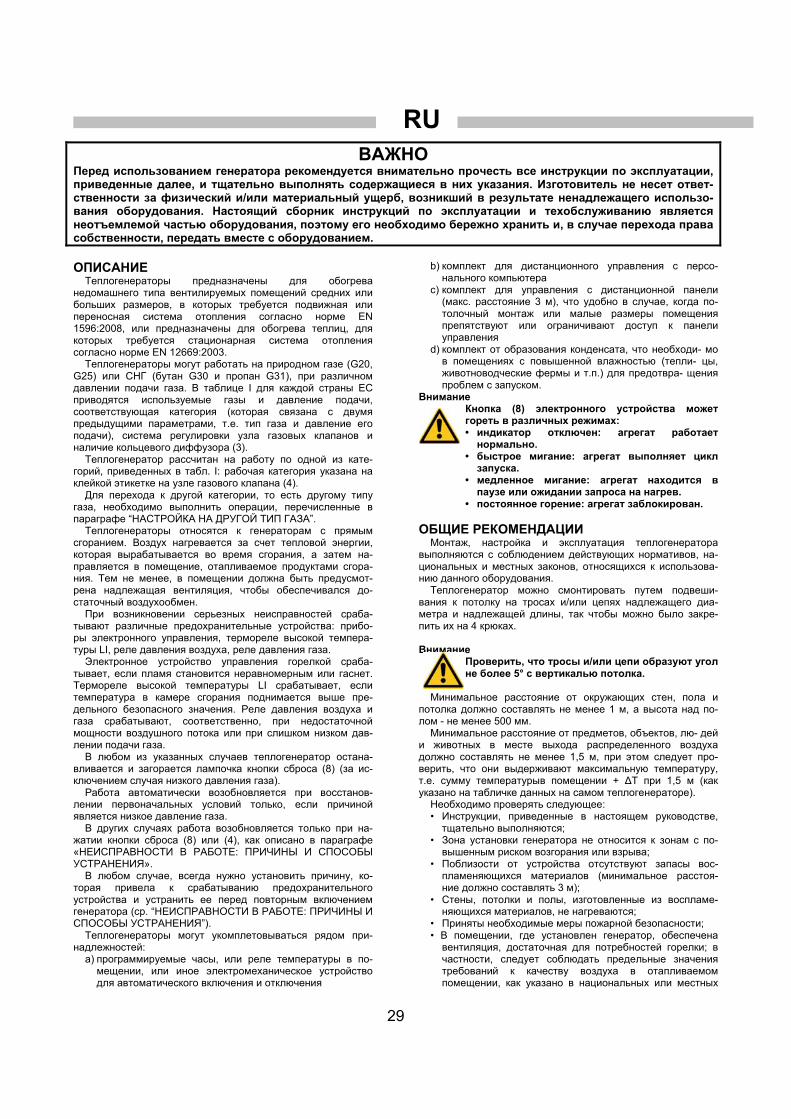
RU
29
ВАЖНО Перед использованием генератора рекомендуется внимательно прочесть все инструкции по эксплуатации, приведенные далее, и тщательно выполнять содержащиеся в них указания. Изготовитель не несет ответ- ственности за физический и/или материальный ущерб, возникший в результате ненадлежащего использо- вания оборудования. Настоящий сборник инструкций по эксплуатации и техобслуживанию является неотъемлемой частью оборудования, поэтому его необходимо бережно хранить и, в случае перехода права собственности, передать вместе с оборудованием. ОПИСАНИЕ Теплогенераторы предназначены для обогрева
недомашнего типа вентилируемых помещений средних или больших размеров, в которых требуется подвижная или переносная система отопления согласно норме EN 1596:2008, или предназначены для обогрева теплиц, для которых требуется стационарная система отопления согласно норме EN 12669:2003. Теплогенераторы могут работать на природном газе (G20,
G25) или СНГ (бутан G30 и пропан G31), при различном давлении подачи газа. В таблице I для каждой страны ЕС приводятся используемые газы и давление подачи, соответствующая категория (которая связана с двумя предыдущими параметрами, т.е. тип газа и давление его подачи), система регулировки узла газовых клапанов и наличие кольцевого диффузора (3). Теплогенератор рассчитан на работу по одной из кате-
горий, приведенных в табл. I: рабочая категория указана на клейкой этикетке на узле газового клапана (4). Для перехода к другой категории, то есть другому типу
газа, необходимо выполнить операции, перечисленные в параграфе “НАСТРОЙКА НА ДРУГОЙ ТИП ГАЗА”. Теплогенераторы относятся к генераторам с прямым
сгоранием. Воздух нагревается за счет тепловой энергии, которая вырабатывается во время сгорания, а затем на-правляется в помещение, отапливаемое продуктами сгора- ния. Тем не менее, в помещении должна быть предусмот- рена надлежащая вентиляция, чтобы обеспечивался до- статочный воздухообмен. При возникновении серьезных неисправностей сраба-
тывают различные предохранительные устройства: прибо- ры электронного управления, термореле высокой темпера- туры LI, реле давления воздуха, реле давления газа. Электронное устройство управления горелкой сраба-
тывает, если пламя становится неравномерным или гаснет. Термореле высокой температуры LI срабатывает, если температура в камере сгорания поднимается выше пре- дельного безопасного значения. Реле давления воздуха и газа срабатывают, соответственно, при недостаточной мощности воздушного потока или при слишком низком дав- лении подачи газа. В любом из указанных случаев теплогенератор остана-
вливается и загорается лампочка кнопки сброса (8) (за ис- ключением случая низкого давления газа). Работа автоматически возобновляется при восстанов-
лении первоначальных условий только, если причиной является низкое давление газа. В других случаях работа возобновляется только при на-
жатии кнопки сброса (8) или (4), как описано в параграфе «НЕИСПРАВНОСТИ В РАБОТЕ: ПРИЧИНЫ И СПОСОБЫ УСТРАНЕНИЯ». В любом случае, всегда нужно установить причину, ко-
торая привела к срабатыванию предохранительного устройства и устранить ее перед повторным включением генератора (ср. “НЕИСПРАВНОСТИ В РАБОТЕ: ПРИЧИНЫ И СПОСОБЫ УСТРАНЕНИЯ”). Теплогенераторы могут укомплетовываться рядом при-
надлежностей: а) программируемые часы, или реле температуры в по- мещении, или иное электромеханическое устройство для автоматического включения и отключения
b) комплект для дистанционного управления с персо- нального компьютера
c) комплект для управления с дистанционной панели (макс. расстояние 3 м), что удобно в случае, когда по- толочный монтаж или малые размеры помещения препятствуют или ограничивают доступ к панели управления
d) комплект от образования конденсата, что необходи- мо в помещениях с повышенной влажностью (тепли- цы, животноводческие фермы и т.п.) для предотвра- щения проблем с запуском.
Внимание Кнопка (8) электронного устройства может гореть в различных режимах: • индикатор отключен: агрегат работает нормально.
• быстрое мигание: агрегат выполняет цикл запуска.
• медленное мигание: агрегат находится в паузе или ожидании запроса на нагрев.
• постоянное горение: агрегат заблокирован. ОБЩИЕ РЕКОМЕНДАЦИИ Монтаж, настройка и эксплуатация теплогенератора
выполняются с соблюдением действующих нормативов, на- циональных и местных законов, относящихся к использова- нию данного оборудования. Теплогенератор можно смонтировать путем подвеши-
вания к потолку на тросах и/или цепях надлежащего диа- метра и надлежащей длины, так чтобы можно было закре- пить их на 4 крюках. Внимание
Проверить, что тросы и/или цепи образуют угол не более 5° с вертикалью потолка.
Минимальное расстояние от окружающих стен, пола и
потолка должно составлять не менее 1 м, а высота над по- лом - не менее 500 мм. Минимальное расстояние от предметов, объектов, лю- дей
и животных в месте выхода распределенного воздуха должно составлять не менее 1,5 м, при этом следует про- верить, что они выдерживают максимальную температуру, т.е. сумму температурыв помещении + ∆T при 1,5 м (как указано на табличке данных на самом теплогенераторе). Необходимо проверять следующее: • Инструкции, приведенные в настоящем руководстве, тщательно выполняются;
• Зона установки генератора не относится к зонам с по- вышенным риском возгорания или взрыва;
• Поблизости от устройства отсутствуют запасы вос- пламеняющихся материалов (минимальное расстоя- ние должно составлять 3 м);
• Стены, потолки и полы, изготовленные из воспламе- няющихся материалов, не нагреваются;
• Приняты необходимые меры пожарной безопасности; • В помещении, где установлен генератор, обеспечена вентиляция, достаточная для потребностей горелки; в частности, следует соблюдать предельные значения требований к качеству воздуха в отапливаемом помещении, как указано в национальных или местных

RU
30
отраслевых нормах и законодательствах. В случае отсутствия норм и/или указаний, вентиляция помещения может быть определена в зависимости от назначения применения, в частности: • обогрев недомашнего типа вентилируемых помещений средних или больших размеров, как указано в норме EN 1596:2008: • минимальный объем отапливаемого помещения следует рассчитывать по уравнению тепловая мощность / объем = 100 Вт/м3. Объем помещения ни в коем случае не должен быть менее 100 м3;
• следует предусмотреть площадь воздухообмена с внешней средой не менее 25 см2 на кВт тепловой мощности, но не менее 250 см2, причем она должна распределяться поровну между верхней и нижней частью.
• обогрев теплиц, как указано в норме EN 12669:2003. • Отсутствуют препятствия или закупорка в воздухово- дах всасывания и/или подачи (пленка или крышки, установленные на устройстве или на стенах; крупно- габаритные предметы вблизи генератора);
• Генератор расположен вблизи от шкафа электропита- ния, характеристики которого соответствуют требуе- мым;
• Для машины предусмотрено неподвижное положение; • Обеспечивается регулярный присмотр за работаю- щим генератором и проверка перед включением;
• В начале каждого сеанса работы, перед включением вилки в розетку, проверяется свободное вращение вентилятора;
• По окончании каждого сеанса работы отключается отсекающий выключатель и закрывается отсечной mкран газа.
Внимание
Не допускается эксплуатация устройства людьми с ограниченными физическими, сен- сорными, умственными способностями (включая детей) или людьми, не обладающи- ми достаточным опытом и знаниями, за ис- ключением ситуаций, когда они действуют под присмотром или по инструкциям по экс- плутации прибора со стороны лица, отвечаю- щего за его безопасность.
ИНСТРУКЦИИ ПО МОНТАЖУ Внимание
Все инструкции, приведенные в данном пара- графе, должны выполняться только квали- фицированным персоналом.
ЭЛЕКТРИЧЕСКИЕ СОЕДИНЕНИЯ Внимание
Линию электропитания генератора необходи- мо оснастить системой заземления и тепло- магнитным выключателем с дифференциаль- ным устройством. Кабель электропитания подсоединяется к электрическому шкафу, оборудованному от- сечным выключателем.
Для всех управляющих и предохранительных устройств
электрические соединения выполнены на заводе-изготови- теле. Перед включением генератора, то есть перед подсое-
динением его к сети электропитания необходимо прове- рить, что характеристики сети электропитания соответ- ствуют данным, приведенным на идентификационной таб- личке.
Внимание Прибор оснащен временным кабелем питания, используемым для рабочего испытания.
Внимание
Временный кабель электропитания следует демонтировать и заменить на кабель типа H07RN-F сечением 1,5 мм2. Зачистка кабеля выполняется так, чтобы провод заземления был длиннее минимум на 2 см.
Подсоединение реле температуры в помещении или
других приспособлений (например, часов) выполняется пу- тем подключения электрического кабеля к разъему тер- мореле (10):
• Извлечь разъем (10) из электрического шкафа, от- крыть его и удалить электрическую перемычку меж- ду выводами 2 и 3;
• Подвести кабель соединения с термореле к выводам 2 и 3 разъема термореле (10);
• Вновь закрыть разъем и установить его в электриче- ский шкаф.
Внимание
Никогда не пытаться управлять включением и отключением генератора, соединяя реле температуры в помещении (или другие устройства управления) с линией электропи- тания.
Монтаж и присоединениевсех принадлежностей расс-
матриваются в отдельных инструкциях, приложенных к каждому дополнительному устройству вместе с инструк- циями по эксплуатации. На электросхеме в настоящем руководстве указано только
электрическое соединение. ПОДСОЕДИНЕНИЕ К ЛИНИИ ПОДАЧИ ТОПЛИВА Внимание
Перед началом монтажа проверить, что ло- кальные условия распределения, тип и дав- ление газа совместимы с текущим состоянием настройки оборудования.
Патрубок подсоединения к трубе подачи газа должен
иметь надлежащие размеры, соответствующие типу мон- тируемой системы. Подсоединение необходимо выполнить через газораспределительное устройство, как показано на рис. 2: газовая труба (1), отсечной кран (2) и антивибра- ционная муфта (3) не входят в комплект поставки и предо- ставляются монтажным предприятием; они подсоединяют- ся к узлу газовых клапанов (4), входящему в комплект по- ставки теплогенератора.
Рис. 2
ПЕРВОЕ ВКЛЮЧЕНИЕ Генератор предназначен для работы по одной из кате-
горий, приведенных в табл. I: клейкая этикетка на узле га-
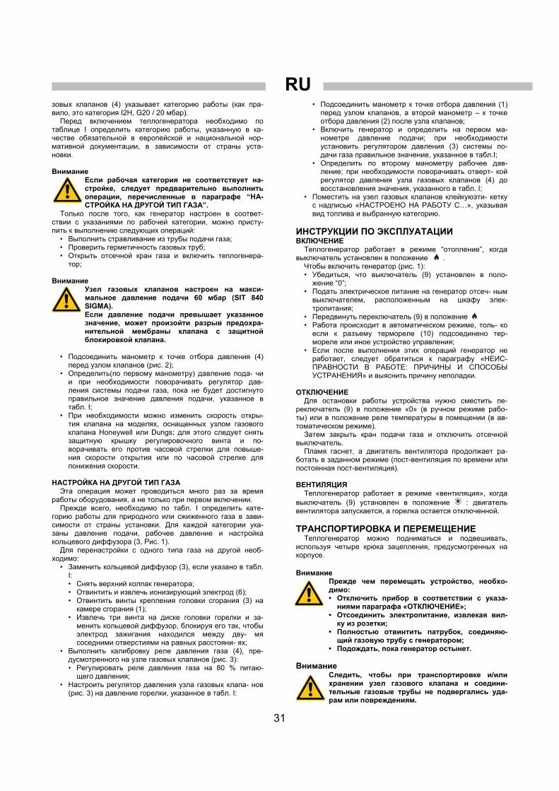
RU
31
зовых клапанов (4) указывает категорию работы (как пра- вило, это категория I2H, G20 / 20 мбар). Перед включением теплогенератора необходимо по
таблице I определить категорию работы, указанную в ка- честве обязательной в европейской и национальной нор- мативной документации, в зависимости от страны уста- новки. Внимание
Если рабочая категория не соответствует на- стройке, следует предварительно выполнить операции, перечисленные в параграфе “НА- СТРОЙКА НА ДРУГОЙ ТИП ГАЗА”.
Только после того, как генератор настроен в соответ- ствии с указаниями по рабочей категории, можно присту- пить к выполнению следующих операций:
• Bыполнить стравливание из трубы подачи газа; • Проверить герметичность газовых труб; • Открыть отсечной кран газа и включить теплогенера- тор;
Внимание
Узел газовых клапанов настроен на макси- мальное давление подачи 60 мбар (SIT 840 SIGMA). Если давление подачи превышает указанное значение, может произойти разрыв предохра- нительной мембраны клапана с защитной блокировкой клапана.
• Подсоединить манометр к точке отбора давления (4) перед узлом клапанов (рис. 2);
• Определить(по первому манометру) давление пода- чи и при необходимости поворачивать регулятор дав- ления системы подачи газа, пока не будет достигнуто правильное значение давления подачи, указанное в табл. I;
• При необходимости можно изменить скорость откры- тия клапана на моделях, оснащенных узлом газового клапана Honeywell или Dungs; для этого следует снять защитную крышку регулировочного винта и по- ворачивать его против часовой стрелки для повыше- ния скорости открытия или по часовой стрелке для понижения скорости.
НАСТРОЙКА НА ДРУГОЙ ТИП ГАЗА Эта операция может проводиться много раз за время
работы оборудования, а не только при первом включении. Прежде всего, необходимо по табл. I определить кате-
горию работы для природного или сжиженного газа в зави- симости от страны установки. Для каждой категории ука- заны давление подачи, рабочее давление и настройка кольцевого диффузора (3, Рис. 1). Для перенастройки с одного типа газа на другой необ-
ходимо: • Заменить кольцевой диффузор (3), если указано в табл.
I: • Снять верхний колпак генератора; • Отвинтить и извлечь ионизирующий электрод (6); • Отвинтить винты крепления головки сгорания (3) на камере сгорания (1);
• Извлечь три винта на диске головки горелки и за- менить кольцевой диффузор, блокируя его так, чтобы электрод зажигания находился между дву- мя соседними отверстиями на равных расстояни- ях;
• Выполнить калибровку реле давления газа (4), пре- дусмотренного на узле газовых клапанов (рис. 3): • Регулировать реле давления газа на 80 % питаю- щего давления;
• Настроить регулятор давления узла газовых клапа- нов (рис. 3) на давление горелки, указанное в табл. I:
• Подсоединить манометр к точке отбора давления (1) перед узлом клапанов, а второй манометр – к точке отбора давления (2) после узла клапанов;
• Включить генератор и определить на первом ма- нометре давление подачи; при необходимости установить регулятором давления (3) системы по- дачи газа правильное значение, указанное в табл.I;
• Определить по второму манометру рабочее дав- ление; при необходимости поворачивать отверт- кой регулятор давления узла газовых клапанов (4) до восстановления значения, указанного в табл. I;
• Поместить на узел газовых клапанов клейкуюэти- кетку с надписью «НАСТРОЕНО НА РАБОТУ С…», указывая вид топлива и выбранную категорию.
ИНСТРУКЦИИ ПО ЭКСПЛУАТАЦИИ ВКЛЮЧЕНИЕ Теплогенератор работает в режиме “отопление”, когда
выключатель установлен в положение . Чтобы включить генератор (рис. 1): • Убедиться, что выключатель (9) установлен в поло- жение “0”;
• Подать электрическое питание на генератор отсеч- ным выключателем, расположенным на шкафу элек- тропитания;
• Передвинуть переключатель (9) в положение • Работа происходит в автоматическом режиме, толь- ко если к разъему термореле (10) подсоединено тер- мореле или иное устройство управления;
• Если после выполнения этих операций генератор не работает, следует обратиться к параграфу «НЕИС- ПРАВНОСТИ В РАБОТЕ: ПРИЧИНЫ И СПОСОБЫ УСТРАНЕНИЯ» и выяснить причину неполадки.
ОТКЛЮЧЕНИЕ Для остановки работы устройства нужно сместить пе-
реключатель (9) в положение «0» (в ручном режиме рабо- ты) или в положение реле температуры в помещении (в ав-томатическом режиме). Затем закрыть кран подачи газа и отключить отсечной
выключатель. Пламя гаснет, а двигатель вентилятора продолжает ра-
ботать в заданном режиме (пост-вентиляция по времени или постоянная пост-вентиляция).
ВЕНТИЛЯЦИЯ Теплогенератор работает в режиме «вентиляция», когда
выключатель (9) установлен в положение : двигатель вентилятора запускается, а горелка остается отключенной.
ТРАНСПОРТИРОВКА И ПЕРЕМЕЩЕНИЕ Теплогенератор можно подниматься и подвешивать,
используя четыре крюка зацепления, предусмотренных на корпусе. Внимание
Прежде чем перемещать устройство, необхо- димо: • Отключить прибор в соответствии с указа- ниями параграфа «ОТКЛЮЧЕНИЕ»;
• Отсоединить электропитание, извлекая вил- ку из розетки;
• Полностью отвинтить патрубок, соединяю- щий газовую трубу с генератором;
• Подождать, пока генератор остынет.
Внимание Следить, чтобы при транспортировке и/или хранении узел газового клапана и соедини- тельные газовые трубы не подвергались уда- рам или повреждениям.

RU
32
ТЕХОБСЛУЖИВАНИЕ Для нормальной работы оборудования необходимо пе-
риодически очищать вентиляторы, камеру сгорания и го- релку.
Внимание
Перед началом какой-либо операции по те- хобслуживанию необходимо: • Отключить прибор в соответствии с указа- ниями параграфа «ОТКЛЮЧЕНИЕ»;
• Отсоединить электропитание, извлекая вил- ку из розетки;
• Закрыть отсечной кран газа; • Подождать, пока генератор остынет.
Обогреватель воздуха требует периодического
технического обслуживания. Периодичность технического обслуживания может меняться. Все работы по переодичекому техническому
обслуживанию должны заносятся в специальный журнал «Технического обслуживания» аттестованным
обслуживающим персоналом с указанием даты проведения работ. Генератор можно очищать и мыть водой. Тем не ме- нее,
следует проверить, что: • кабель электропитания отсоединен и вынут из розет- ки питания
• все ппанели доступа полностью закрыты • струи воды не применяются на расстоянии ближе 2 м • генератор полностью высушен до того, как кабель электропитания снова подсоединяют
Внимание
Ненадлежащие способы очистки генератора могут привести к материальному ущербу и травмам.
Очистка выполняется путем удаления посторонних
предметов, оставшихся на решетках всасывания вентиля- торов.
Периодичность технического обслуживания Наименование работ по техническому обслуживанию
ежедневно 2 недели 6 месяцев годовой
Проверьте теплогенератор X
Проверьте монтаж газового шланга X
Очистите машины X
Прочистите газовый фильтр X
Прочистите вентилятор, двигатель и внутренние оболочки X
Проверьте и почистите реле давления воздуха X
Очистить и проверить / отрегулировать настройки электрода зажигания и электрода ионизации
X
Проверьте и прочистите камеру сгорания X
Проверьте электрические компоненты X
Проверьте и прочистите газовое сопло X
Проверьте давление газа на выходе газового клапана X
Проверьте термостат безопасности X
Проверьте и протестируйте газовую горелку X
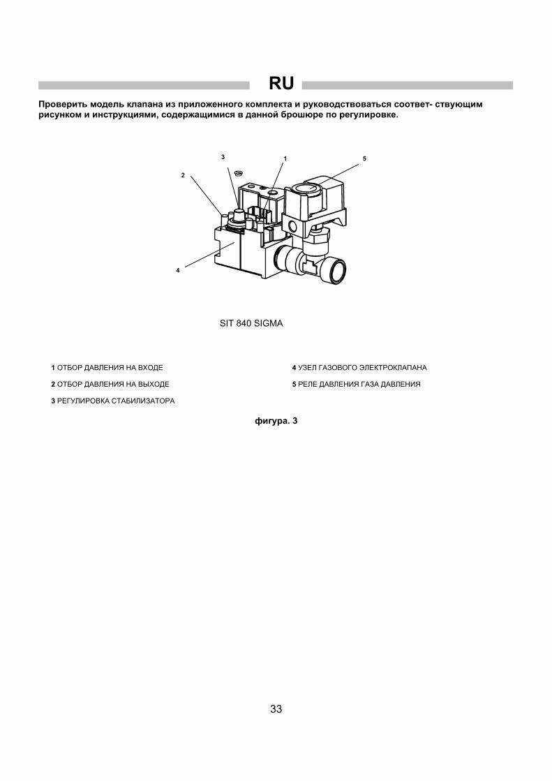
RU
33
Проверить модель клапана из приложенного комплекта и руководствоваться соответ- ствующим рисунком и инструкциями, содержащимися в данной брошюре по регулировке.
1 ОТБОР ДАВЛЕНИЯ НА ВХОДЕ 2 ОТБОР ДАВЛЕНИЯ НА ВЫХОДЕ 3 РЕГУЛИРОВКА СТАБИЛИЗАТОРА
4 УЗЕЛ ГАЗОВОГО ЭЛЕКТРОКЛАПАНА 5 РЕЛЕ ДАВЛЕНИЯ ГАЗА ДАВЛЕНИЯ
фигура. 3
SIT 840 SIGMA
3 1
2
4
5

RU
34
НЕИСПРАВНОСТИ В РАБОТЕ, ПРИЧИНЫ, СПОСОБЫ УСТРАНЕНИЯ
НЕИСПРАВНОСТИ В РАБОТЕ ПРИЧИНЫ СПОСОБЫ УСТРАНЕНИЯ
• Проверить характеристики сети электропитания • Проверить электрические соединения • Нет электропитания
• Проверить целостность предохранителя • Неправильное положение главного выключателя
• Выбрать правильное положение
• Проверить положение термореле • Неправильная работа реле температуры в помещении • Проверить исправность термореле
• Проверить, что была выполнена продувка трубы подачи газа • Сработал выключатель по давлению газа по
причине отсутствия газа • Проверить давление подачи газа
• Проверить отсутствие засорений на решетках всасывания и подачи
• Проверить свободное вращение вентилятора • Сработало реле давления воздуха из-за неисправности вентилятора
• Проверить электродвигатель и конденсатор;в случае неисправности заменить
• Генератор не включается
• Сработало реле давления воздуха из-за неисправности реле давления
• Заменить реле давления
• Ионизирующий электрод не определяет наличия пламени • Извлечь датчик пламени и очистить его
• Проверить, что решетки всасывания и подачи не засорены
• Проверить хорошую вентиляцию в помещении
• Проверить, что горячий воздух выходит свободно
• Сработало защитное термореле из-за высокой температуры в камере сгорания
• Проверить, что мощность расхода или давление газа не слишком высоки
• Срабатывает устройство управления из-за неравномерной работы горелки
• Обратиться в службу техпомощи
• Неисправность электронного устройства управления
• Проверить устройство, при необходимости заменить
• Генератор останавливается и зажигается индикатор (8)
• Неисправность термореле • Проверить термореле, при необходимости заменить
• Срабатывает термореле горелки • Распределительные воздушные каналы имеют чрезмерную длину или слишком маленький диаметр
• Генератор останавливается и снова запускается, а сигнальная лампочка (8) не загорается
• Сработал выключатель по давлению газа по причине внезапного падения давления подачи
• Проверить давление подачи газа
• Посторонние предметы на лопастях вентилятора
• Удалить посторонние предметы • Повышенный уровень шума или вибраций вентилятора
• Недостаточная циркуляция воздуха • Убрать все возможные препятствия для прохода воздуха
Если используя приведенные выше проверки и способы устранения не была обнаружена причина неисправности, просим вас обратиться в ближайший официальный центр продаж и сервисного обслуживания.

35

36
SCHEMA ELETTRICO - SCHEMA ELECTRIQUE – SCHALTSCHEMA WIRING DIAGRAM - ESQUEMA ELETRICO - ЭЛЕКТРИЧЕСКАЯ СХЕМА
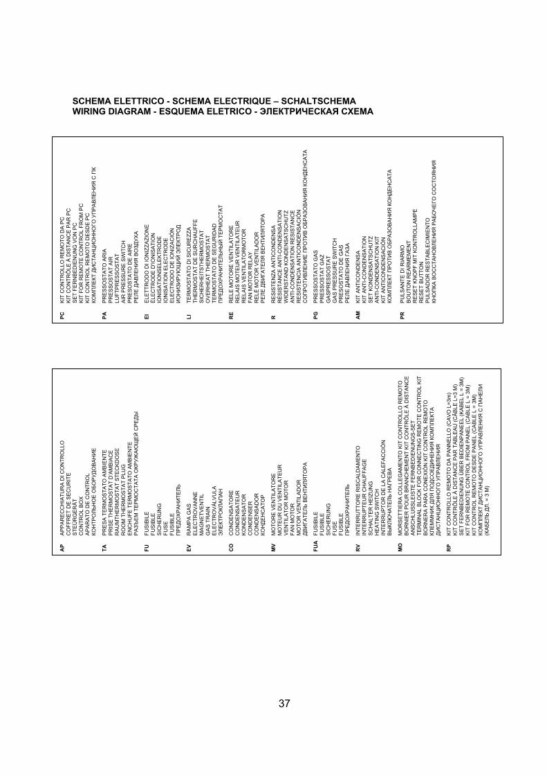
37
SCHEMA ELETTRICO - SCHEMA ELECTRIQUE – SCHALTSCHEMA WIRING DIAGRAM - ESQUEMA ELETRICO - ЭЛЕКТРИЧЕСКАЯ СХЕМА
AP
A
PP
AR
EC
CH
IAT
UR
A D
I CO
NT
RO
LLO
C
OF
FR
ET
DE
SE
CU
RIT
E
ST
EÜ
RG
ER
ÄT
C
ON
TR
OL
BO
X
AP
AR
AT
O D
E C
ON
TR
OL
КОНТРОЛЬНОЕ
ОБОРУДОВАНИЕ
T
A
PR
ES
A T
ER
MO
ST
AT
O A
MB
IEN
TE
P
RIS
E T
HE
RM
OS
TA
T D
’AM
BIA
CE
R
AU
MT
HE
RM
OS
TA
T S
TE
CK
DO
SE
R
OO
M T
HE
RM
OS
TA
T P
LUG
E
NC
HU
FE
TE
RM
OS
TA
TO
AM
BIE
NT
E
РАЗЪЕМ
ТЕРМОСТАТА
ОКРУЖАЮЩЕЙ
СРЕДЫ
F
U
FU
SIB
ILE
F
US
IBL
E
SIC
HE
RU
NG
F
US
E
FU
SIB
LE
ПРЕДОХРАНИТЕЛЬ
E
V
RA
MP
A G
AS
E
LEC
TR
OV
AN
NE
M
AG
NE
TV
EN
TIL
G
AS
TR
AIN
E
LEC
TR
OV
ÁLV
UL
A
ЭЛЕКТРОКЛАПАН
C
O
CO
ND
EN
SA
TO
RE
C
ON
DE
NS
AT
EU
R
KO
ND
EN
SA
TO
R
CO
ND
EN
SE
R
CO
ND
EN
SA
DO
R
КОНДЕНСАТОР
MV
M
OT
OR
E V
EN
TIL
AT
OR
E
MO
TE
UR
DU
VE
NT
ILA
TE
UR
V
EN
TIL
AT
OR
MO
TO
R
FA
N M
OT
OR
M
OT
OR
VE
NT
ILA
DO
R
ДВИГА
ТЕЛЬ
ВЕНТИЛЯТОРА
FU
A
FU
SIB
ILE
F
US
IBL
E
SIC
HE
RU
NG
F
US
E
FU
SIB
LE
ПРЕДОХРАНИТЕЛЬ
R
V
INT
ER
RU
TT
OR
E R
ISC
ALD
AM
EN
TO
IN
TE
RR
UP
TE
UR
CH
AU
FF
AG
E
SC
HA
LTE
R H
EIZ
UN
G
HE
AT
ING
SW
ITC
H
INT
ER
RU
PT
OR
DE
LA
CA
LE
FA
CC
IÓN
ВЫКЛЮЧАТЕЛЬ
НАГР
ЕВА
MO
M
OR
SE
TT
IER
A C
OLL
EG
AM
EN
TO
KIT
CO
NT
RO
LLO
RE
MO
TO
B
OR
NIE
R P
OU
R B
RA
NC
HE
ME
NT
KIT
CO
NT
RÔ
LE À
DIS
TA
NC
E
AN
SC
HLU
SS
LEIS
TE
FE
RN
BE
DIE
NU
NG
S-S
ET
T
ER
MIN
AL
BLO
CK
FO
R C
ON
NE
CT
ING
RE
MO
TE
CO
NT
RO
L K
IT
BO
RN
ER
A P
AR
A C
ON
EX
IÓN
KIT
CO
NT
RO
L R
EM
OT
O
КЛЕММНИК
ДЛЯ
ПОДСОЕДИНЕНИЯ
КОМПЛЕКТА
ДИСТАНЦИОННОГО
УПРАВЛЕНИЯ
RP
K
IT C
ON
TR
OLL
O R
EM
OT
O D
A P
AN
NE
LLO
(C
AV
O L
=3
m)
KIT
CO
NT
RÔ
LE À
DIS
TA
NC
E P
AR
TA
BL
EA
U (
CÂ
BLE
L=
3 M
) S
ET
FE
RN
BE
DIE
NU
NG
ÜB
ER
BE
DIE
NP
AN
EE
L (K
AB
EL
L =
3M
) K
IT F
OR
RE
MO
TE
CO
NT
RO
L F
RO
M P
AN
EL
(CA
BLE
L =
3M
) K
IT C
ON
TR
OL
RE
MO
TO
DE
SD
E P
AN
EL
(CA
BLE
L =
3M
) КОМПЛЕКТ
ДИСТАНЦИОННОГО
УПРАВЛЕНИЯ
С ПАНЕЛИ
(КАБЕЛЬ
ДЛ
. = 3
М)
PC
K
IT C
ON
TR
OLL
O R
EM
OT
O D
A P
C
KIT
CO
NT
RÔ
LE À
DIS
TA
NC
E P
AR
PC
S
ET
FE
RN
BE
DIE
NU
NG
VO
N P
C
KIT
FO
R R
EM
OT
E C
ON
TR
OL
FR
OM
PC
K
IT C
ON
TR
OL
RE
MO
TO
DE
SD
E P
C
КОМПЛЕКТ
ДИСТАНЦИОННОГО
УПРАВЛЕНИЯ
С ПК
PA
P
RE
SS
OS
TA
TO
AR
IA
PR
ES
SO
ST
AT
AIR
LU
FT
PR
ES
SO
ST
AT
A
IR P
RE
SS
UR
E S
WIT
CH
P
RE
SO
ST
AT
O D
E A
IRE
РЕЛЕ
ДАВЛЕНИЯ
ВОЗДУХА
EI
ELE
TT
RO
DO
DI I
ON
IZZ
AZ
ION
E
ÉLE
CT
RO
DE
D'IO
NIS
AT
ION
IO
NIS
AT
ION
SE
LEK
TR
OD
E
ION
ISA
TIO
N E
LE
CT
RO
DE
E
LEC
TR
OD
O D
E IO
NIZ
AC
IÓN
ИОНИЗИРУЮЩИЙ
ЭЛЕКТРОД
LI
T
ER
MO
ST
AT
O D
I SIC
UR
EZ
ZA
T
HE
RM
OS
TA
T D
E S
UR
CH
AU
FF
E
SIC
HE
RH
EIT
ST
HE
RM
OS
TA
T
OV
ER
HE
AT
TH
ER
MO
ST
AT
T
ER
MO
ST
AT
O D
E S
EG
UR
IDA
D
ПРЕДОХРАНИТЕЛЬНЫЙ
ТЕРМОСТАТ
RE
R
ELE
MO
TO
RE
VE
NT
ILA
TO
RE
R
ELA
IS M
OT
EU
R V
EN
TIL
AT
EU
R
RE
LAIS
VE
NT
ILA
TO
RM
OT
OR
F
AN
MO
TO
R R
ELA
Y
RE
LÉ M
OT
OR
VE
NT
ILA
DO
R
РЕЛЕ
ДВИГА
ТЕЛЯ
ВЕНТИЛЯТОРА
R
RE
SIS
TE
NZ
A A
NT
ICO
ND
EN
SA
R
ÉS
IST
AN
CE
AN
TI-
CO
ND
EN
SA
TIO
N
WID
ER
ST
AN
D K
ON
DE
NS
AT
SC
HU
TZ
A
NT
I-C
ON
DE
NS
AT
ION
RE
SIS
TA
NC
E
RE
SIS
TE
NC
IA A
NT
ICO
ND
EN
SA
CIÓ
N
СОПРОТИВЛЕНИЕ
ПРОТИВ
ОБРАЗОВАНИЯ
КОНДЕНСАТА
PG
P
RE
SS
OS
TA
TO
GA
S
PR
ES
SO
ST
AT
GA
Z
GA
SP
RE
SS
OS
TA
T
GA
S P
RE
SS
UR
E S
WIT
CH
P
RE
SO
ST
AT
O D
E G
AS
РЕЛЕ
ДАВЛЕНИЯ
ГАЗА
AM
K
IT A
NT
ICO
ND
EN
SA
K
IT A
NT
I-C
ON
DE
NS
AT
ION
S
ET
KO
ND
EN
SA
TS
CH
UT
Z
AN
TI-
CO
ND
EN
SA
TIO
N K
IT
KIT
AN
TIC
ON
DE
NS
AC
IÓN
КОМПЛЕКТ
ПРОТИВ
ОБРАЗОВАНИЯ
КОНДЕНСАТА
P
R
PU
LSA
NT
E D
I RIA
RM
O
BO
UT
ON
RE
AR
ME
ME
NT
R
ES
ET
KN
OP
F M
IT K
ON
TR
OL
LAM
PE
R
ES
ET
BU
TT
ON
P
ULS
AD
OR
RE
ST
AB
LEC
IMIE
NT
O
КНОПКА
ВОССТАНОВЛЕНИЯ
РАБОЧЕГО
СОСТОЯНИЯ

38
45 kW
Tab. I

39
ETICHETTA IDENTIFICAZIONE PRODOTTO – PLAQUETTE IDENTIFICATION PRODUIT TYPENSCHILD - PRODUCT IDENTIFICATION PLATE ETIQUETA DE IDENTIFICACIÓN DEL PRODUCTO – ПАСПОРТНАЯ ТАБЛИЧКА ИЗДЕЛИЯ 1 COSTRUTTORE
CONSTRUCTEUR HERSTELLER MANUFACTURER FABRICANTE ИЗГОТОВИТЕЛЬ FABRIKANT PRODUCENT
2 MODELLO
MODÈLE MODELL MODEL MODELO МОДЕЛЬ MODEL MODEL
3 TIPO
TYPE TYP TYPE TIPO ТИП TYPE TYP
4 GRADO DI PROTEZIONE
INDICE DE PROTECTION SCHUTZART PROTECTION LEVEL GRADO DE PROTECCIÓN СТЕПЕНЬ ЗАЩИТЫ BESCHERMINGSGRAAD STOPIEŃ OCHRONY
5 NUMERO DI SERIE
NUMÉRO DE SÉRIE SERIENNUMMER SERIAL NUMBER NÚMERO DE SERIE ПАСПОРТНЫЙ НОМЕР SERIENUMMER NUMER SERYJNY
6 PORTATA DI ARIA DÉBIT D'AIR LUFTFÖRDERMENGE AIR OUTPUT CAUDAL DE AIRE РАСХОД ВОЗДУХА LUCHTDEBIET NATĘŻENIE PRZEPŁYWU POWIETRZA
7 INCREMENTO DI TEMPERATURA AUGMENTATION DE TEMPÉRATURE TEMPERATURANSTIEG TEMPERATURE RISE INCREMENTO DE TEMPERATURA ПОВЫШЕНИЕ ТЕМПЕРАТУРЫ TEMPERATUURTOENAME ZWIĘKSZENIE TEMPERATURY
8 POTENZA TERMICA NOMINALE
PUISSANCE THERMIQUE NOMINALE WÄRMELEISTUNG BEWERTET NOMINAL HEATING OUTPUT POTENCIA TÉRMICA NOMINAL ТЕПЛОВОЙ НОМИНАЛЬНАЯ МОЩНОСТЬ NOMINAAL THERMISCH VERMOGEN: MOC CIEPLNA ZNAMIONOWA
9 POTENZA TERMICA MISURATA
PUISSANCE THERMIQUE MESURE GEMESSENEN WÄRMELEISTUNG MEASURED HEATING OUTPUT POTENCIA TÉRMICA MEDIDO ТЕПЛОВАЯ МОЩНОСТЬ ИЗМЕРЕНИЯ GEMETEN THERMISCH VERMOGEN MOC CIEPLNA ZMIERZONA
10 CONSUMO GAS MISURATO
CONSOMMATION GAZ MESURE GEMESSENEN GASVERBRAUCH MEASURED GAS CONSUMPTION CONSUMO GAS MEDIDO РАСХОД ГАЗА ИЗМЕРЕНИЯ GEMETEN GASVERBRUIK ZUŻYCIE GAZU ZMIERZONA
11 ALIMENTAZIONE ELETTRICA ALIMENTATION ÉLECTRIQUE STROMVERSORGUNG ELECTRICAL SUPPLY ALIMENTACIÓN ELÉCTRICA ЭЛЕКТРОПИТАНИЕ ELEKTRISCHE VOEDING ZASILANIE ELEKTRYCZNE
12 CORRENTE ASSORBITA COURANT ABSORBÉ STROMAUFNAHME AMPERAGE CORRIENTE ABSORBIDA ПОТРЕБЛЯЕМЫЙ ТОК STROOMVERBRUIK POBÓR PRĄDU
13 SIGLA CERTIFICAZIONE (PIN)
SIGLE CERTIFICATION (PIN) CE-PRÜFNUMMER (PIN) CERTIFICATION INITIALS (PIN) SIGLA CERTIFICACIÓN (PIN) СИМВОЛ СЕРТИФИКАТА (ПИН-КОД) CERTIFICATIECODE (PIN) OZNACZENIE CERTYFIKACJI (PIN)
7
1
3
2
5
129
10
11
8
4
13
6
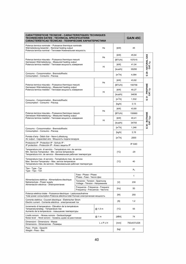
40
CARATTERISTICHE TECNICHE - CARACTERISTIQUES TECHNIQUES TECHNISCHEN DATEN - TECHNICAL SPECIFICATIONS CARACTERÍSTICAS TÉCNICAS - ТЕХНИЧЕСКИЕ ХАРАКТЕРИСТИКИ
GA/N 45C
Potenza termica nominale – Puissance thermique nominale Wärmeleistung bewertet – Nominal heating output Potencia termica nominal - Тепловая Номинальная мощность
Hs [kW] 45
[kW] 45,64 Hs
[BTU/h] 157015
[kW] 41,04
Potenza termica misurata – Puissance thermique mesurè Gemessen Wärmeleistung – Measured heating output Potencia termica medidol - Тепловая мощность измерения
Hi [kcal/h] 35295
Consumo - Consommation - Brennstoffverbr. Consumption - Consumo - Расход
[m3/h] 4,084 G 2
0 -
NA
TU
RA
L G
AS
C
AT
. I2
H
[kW] 43,82 Hs
[BTU/h] 150756
[kW] 40,27
Potenza termica misurata – Puissance thermique mesurè Gemessen Wärmeleistung – Measured heating output Potencia termica medidol - Тепловая мощность измерения
Hi [kcal/h] 34636
[m3/h] 1,532 Consumo - Consommation - Brennstoffverbr. Consumption - Consumo - Расход
[kg/h] 3,13
G 3
1 -
PR
OP
AN
E
CA
T. I
3P
[kW] 43,80 Hs
[BTU/h] 150660
[kW] 40,41
Potenza termica misurata – Puissance thermique mesurè Gemessen Wärmeleistung – Measured heating output Potencia termica medidol - Тепловая мощность измерения
Hi [kcal/h] 34755
[m3/h] 1,246 Consumo - Consommation - Brennstoffverbr. Consumption - Consumo - Расход
[kg/h] 3,19
G 3
0 -
BU
TH
AN
E
CA
T. I
3B
/P
Portata d'aria - Débit d'air - Nenn-Lufleistung Air output - Capacidad aire - Мощность подачи воздуха
[m3/h] 2500
Protezione IP - Protection IP - Schutz IP - IP protection - Protección IP - Класс защиты IP
IP X4D
Temperatura min. di servizio - Température min. de service Min. Service-Temperatur - Min. service temperature Temperatura mín. de servicio - Минимальная рабочая температура
[°C] -20
Temperatura max. di servizio - Température max. de service Max. Service-Temperatur - Max. service temperature Temperatura máx. de servicio - Максимальная рабочая температура
[°C] 40
Tipo - Type - Typ Type - Tipo - Тип
A3
Fase - Phase - Phase Phase - Fase - Число фаз
1
Tensione - Tension - Spannung Voltage - Ténsion - Напряжение
[V] 230 Alimentazione elettrica - Alimentatione électrique Netzanscluss - Power supply Alimentación eléctrica - Электропитание
Frequenza - Fréquence - Frequenz Frequency - Frecuencia - Частота
[Hz] 50
Potenza elettrica totale - Puissance électrique - Leistunsaufnahme Total power consumption-Potencia eléctrica total-Полная электрическая мощность
[W] 250
Corrente elettrica - Courant électrique - Elektrischer Strom Electric current - Corriente eléctrica - электрический ток
[A] 1,2
Incremento di temperatura - Elévation de la température Temperaturanstieg - Temperature rise Aumento de la temperatura - повышение температуры
@ 1,5 m [°C] 55
Livello sonoro - Niveau sonore - Geräuschpegel Noise level - Nivel sonoro - Уровень шума на расстоянии
@ 1 m [dBA] 74
Dimensioni - Dimensions - Masse Dimensions - Dimensiones - Размеры
L x P x H [mm] 792x437x326
Peso - Poids - Gewicht Weight - Peso - Вес
[kg] 21