CILINDRI ANTIROTAZIONE CON STELI GEMELLATI - TWIN … · Seals: piston rod of poliurethane, others...
6
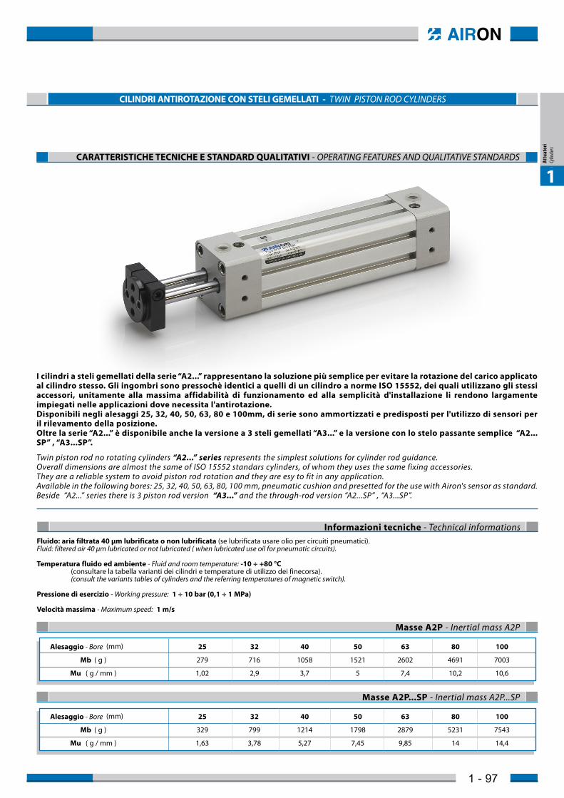
1 - 97 1 1 Attuatori Cylinders CILINDRI ANTIROTAZIONE CON STELI GEMELLATI - TWIN PISTON ROD CYLINDERS CARATTERISTICHE TECNICHE E STANDARD QUALITATIVI - OPERATING FEATURES AND QUALITATIVE STANDARDS I cilindri a steli gemellati della serie “A2...” rappresentano la soluzione più semplice per evitare la rotazione del carico applicato al cilindro stesso. Gli ingombri sono pressochè identici a quelli di un cilindro a norme ISO 15552, dei quali utilizzano gli stessi accessori, unitamente alla massima affidabilità di funzionamento ed alla semplicità d'installazione li rendono largamente impiegati nelle applicazioni dove necessita l'antirotazione. Disponibili negli alesaggi 25, 32, 40, 50, 63, 80 e 100mm, di serie sono ammortizzati e predisposti per l'utilizzo di sensori per il rilevamento della posizione. Oltre la serie “A2...” è disponibile anche la versione a 3 steli gemellati “A3...” e la versione con lo stelo passante semplice “A2... SP” , “A3...SP”. Twin piston rod no rotating cylinders “A2...” series represents the simplest solutions for cylinder rod guidance. Overall dimensions are almost the same of ISO 15552 standars cylinders, of whom they uses the same fixing accessories. They are a reliable system to avoid piston rod rotation and they are esy to fit in any application. Available in the following bores: 25, 32, 40, 50, 63, 80, 100 mm, pneumatic cushion and presetted for the use with Airon's sensor as standard. Beside “A2...” series there is 3 piston rod version “A3...” and the through-rod version “A2...SP” , “A3...SP”. Informazioni tecniche - Technical informations Fluido: aria filtrata 40 µm lubrificata o non lubrificata (se lubrificata usare olio per circuiti pneumatici). Fluid: filtered air 40 µm lubricated or not lubricated ( when lubricated use oil for pneumatic circuits). Temperatura fluido ed ambiente - Fluid and room temperature: -10 ÷ +80 °C (consultare la tabella varianti dei cilindri e temperature di utilizzo dei finecorsa). (consult the variants tables of cylinders and the referring temperatures of magnetic switch). Pressione di esercizio - Working pressure: 1 ÷ 10 bar (0,1 ÷ 1 MPa) Velocità massima - Maximum speed: 1 m/s Alesaggio - Bore (mm) 25 32 40 50 63 80 100 Mb ( g ) 279 716 1058 1521 2602 4691 7003 Mu ( g / mm ) 1,02 2,9 3,7 5 7,4 10,2 10,6 Alesaggio - Bore (mm) 25 32 40 50 63 80 100 Mb ( g ) 329 799 1214 1798 2879 5231 7543 Mu ( g / mm ) 1,63 3,78 5,27 7,45 9,85 14 14,4 Masse A2P - Inertial mass A2P Masse A2P...SP - Inertial mass A2P...SP
Transcript of CILINDRI ANTIROTAZIONE CON STELI GEMELLATI - TWIN … · Seals: piston rod of poliurethane, others...
1 - 97
1
Att
uato
ri
Cylin
ders
1
Attu
ator
i Cy
linde
rs
CILINDRI ANTIROTAZIONE CON STELI GEMELLATI - TWIN PISTON ROD CYLINDERS
CARATTERISTICHE TECNICHE E STANDARD QUALITATIVI - OPERATING FEATURES AND QUALITATIVE STANDARDS
I cilindri a steli gemellati della serie “A2...” rappresentano la soluzione più semplice per evitare la rotazione del carico applicato al cilindro stesso. Gli ingombri sono pressochè identici a quelli di un cilindro a norme ISO 15552, dei quali utilizzano gli stessi accessori, unitamente alla massima affidabilità di funzionamento ed alla semplicità d'installazione li rendono largamente impiegati nelle applicazioni dove necessita l'antirotazione. Disponibili negli alesaggi 25, 32, 40, 50, 63, 80 e 100mm, di serie sono ammortizzati e predisposti per l'utilizzo di sensori per il rilevamento della posizione. Oltre la serie “A2...” è disponibile anche la versione a 3 steli gemellati “A3...” e la versione con lo stelo passante semplice “A2...SP” , “A3...SP”.
Twin piston rod no rotating cylinders “A2...” series represents the simplest solutions for cylinder rod guidance. Overall dimensions are almost the same of ISO 15552 standars cylinders, of whom they uses the same fixing accessories. They are a reliable system to avoid piston rod rotation and they are esy to fit in any application. Available in the following bores: 25, 32, 40, 50, 63, 80, 100 mm, pneumatic cushion and presetted for the use with Airon's sensor as standard.Beside “A2...” series there is 3 piston rod version “A3...” and the through-rod version “A2...SP” , “A3...SP”.
Informazioni tecniche - Technical informationsFluido: aria filtrata 40 µm lubrificata o non lubrificata (se lubrificata usare olio per circuiti pneumatici).Fluid: filtered air 40 µm lubricated or not lubricated ( when lubricated use oil for pneumatic circuits).
Temperatura fluido ed ambiente - Fluid and room temperature: -10 ÷ +80 °C (consultare la tabella varianti dei cilindri e temperature di utilizzo dei finecorsa). (consult the variants tables of cylinders and the referring temperatures of magnetic switch).
Pressione di esercizio - Working pressure: 1 ÷ 10 bar (0,1 ÷ 1 MPa)
Velocità massima - Maximum speed: 1 m/s
Alesaggio - Bore (mm) 25 32 40 50 63 80 100
Mb ( g ) 279 716 1058 1521 2602 4691 7003
Mu ( g / mm ) 1,02 2,9 3,7 5 7,4 10,2 10,6
Alesaggio - Bore (mm) 25 32 40 50 63 80 100
Mb ( g ) 329 799 1214 1798 2879 5231 7543
Mu ( g / mm ) 1,63 3,78 5,27 7,45 9,85 14 14,4
Masse A2P - Inertial mass A2P
Masse A2P...SP - Inertial mass A2P...SP

1 - 98
MASSIMO CARICO AMMISSIBILE - MAXIMUM ALLOWABLE LOAD
Diagramma di flessione e torsione - Deflection and torque diagram
Mt
MtCorsa - StrokeCorsa - Stroke
Ft Ø25Ø25Ø32Ø40Ø50Ø63Ø80Ø100
Ø32Ø40Ø50Ø63Ø80Ø100
0 100 200 300 400 500Corsa - Stroke (mm)
Mass
imo
caric
o am
miss
ibile
- M
ax a
llowa
ble lo
ad(N
)
123456789
10111213141516
0 100 200 300 400 500Corsa - Stroke (mm)
Mass
imo
caric
o am
miss
ibile
- M
ax a
llowa
ble lo
ad(N
)
102030405060708090
100110120130140150160
Flessione - Deflection
Flessione - Deflection
Momento Torcente - Torque
Momento Torcente - Torque
Diagramma di flessione e torsione - Deflection and torque diagram
Corsa - Stroke
Mt
MtCorsa - Stroke
Ft
0 100 200 300 400 500Corsa - Stroke (mm)
0 100 200 300 400 500Corsa - Stroke (mm)
2468
10121416182022
Mass
imo
caric
o am
miss
ibile
Max
allo
wable
load
(N)
Mass
imo
caric
o am
miss
ibile
Max
allo
wable
load
(N)
102030405060708090
100110
Ø32Ø40Ø50Ø63
Ø32Ø40Ø50Ø63
Per il calcolo della massa dei cilindri si utilizza la seguente formula:To evaluate the inertial mass of cylinders please use the following formula:
NB: Le differenze tra le masse, per le versioni magnetiche e non magnetiche, sono trascurabili.NB: The differences between the masses from magnetic and non-magnetic versions, are negligible.
Mt = Massa totale (g) - total massMb = Massa cilindro corsa 0 (g) - Cylinder mass stroke 0Mu = Massa per millimetro di corsa (g / mm) -Mass per millimeter of strokeC = Corsa del cilindro (mm) - Stroke of cylinder
M t = M b + ( M u • C )
Alesaggio - Bore (mm) 32 40 50 63
Mb ( g ) 752 1128 1597 2730
Mu ( g / mm ) 3,4 5,14 5,88 8,98
Alesaggio - Bore (mm) 32 40 50 63
Mb ( g ) 835 1284 1874 3007
Mu ( g / mm ) 4,28 6,7 8,33 11,4
Masse A3P - Inertial mass A3P
Masse A3P...SP - Inertial mass A3P...SP
A2 ... SP
A3 ... SP
A2 ...
A3 ...
Materiali standard - Standard materialTestate: alluminio anodizzatoStelo: acciaio C 45 cromato rettificatoCamicia: alluminio profilato estruso ed anodizzatoTenute: steli in poliuretano, altre in gomma NBRAmmortizzo: pneumatico (eccetto A2N 25)Piastra: acciaio FE 370 brunito
Covers: anodized aluminiumPiston rod: C45 cromium plated steel retifiedBarrel: anodized profiled aluminiumSeals: piston rod of poliurethane, others of NBRCushioning: pneumatic (except A2N 25)Plate: FE 370 black galvanized
1 - 99
1
Att
uato
ri
Cylin
ders
1
Attu
ator
i Cy
linde
rs
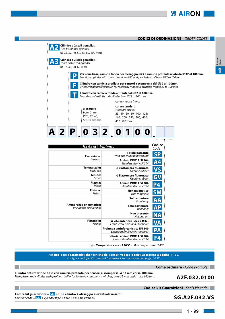
CODICI DI ORDINAZIONE - ORDER CODES
Codice kit guarnizioni = SG + tipo cilindro + alesaggio + eventuali varianti.Seals kit code = SG + cylinder type + bore + possible versions. SG.A2F.032.VS
Codice kit Guarnizioni - Seals kit code
Cilindro antirotazione base con camicia profilata per sensori a scomparsa, ø 32 mm corsa 100 mm.Twin piston rod cylinder with profiled baller for foldaway magnetic switches, bore 32 mm and stroke 100 mm. A2F.032.0100
Come ordinare - Code example
alesaggiobore (mm)Ø25; 32; 40;50; 63; 80; 100.
corsa - stroke (mm):
corse standard:standard stroke:25; 40; 50; 80; 100; 125; 160; 200; 250; 300; 400; 450; 500 mm.
P Versione base, camicia tonda per alesaggio Ø25 e camicia profilata a lobi dal Ø32 al 100mm.Standard cylinder with round barrel for Ø25 and profiled barrel from Ø32 to 100 mm.
F Cilindro con camicia profilata per sensori a scomparsa dal Ø32 al 100mm.Cylinder with profiled barrel for foldaway magnetic switches from Ø32 to 100 mm.
T Cilindro con camicia tonda e tiranti dal Ø32 al 100mm.Round barrel with tie rod cylinder from Ø32 to 100 mm.
(Ø 25, 32, 40, 50, 63, 80, 100 mm)
(Ø 32, 40, 50, 63 mm)
A 2 0 3 2 0 1 0 0P
Per tipologie e caratteristiche tecniche dei sensori vedere la relativa sezione a pagina 1-139.For types and specifications of the sensors see the section on page 1-139.
Codice Code
SP A4 VS GV P4 SM AA AP NA VA PA F4
1 stelo passanteWith one through piston rod
Acciaio INOX AISI 304Stainless steel AISI 304
*) Elastomero fluoruratoFluorine rubber
*) Elastomero fluoruratoFluorine rubber
Acciaio INOX AISI 304Stainless steel AISI 304
Non magneticoNon magnetic
Solo anterioreFront only
Solo posterioreRear only
Non presenteNot present
A vite anteriore (Ø25 e Ø32)Front screw (Ø25 and Ø32 bore)
Prolunga antinfortunistica EN 349Extension for EN 349 standards
Viteria: acciaio INOX AISI 304Screws: stainless steel AISI 304
Esecuzione: Version:
Tenuta stelo:Rod seal:Tenute:
Seals:Piastra:
Plate:
Pistone:Piston:
Ammortizzo pneumatico:Pneumatic cushioning:
Fissaggio:Fixing:
Varianti -Variants
Cilindro a 2 steli gemellati.Two piston rod cylinder.
Cilindro a 3 steli gemellati.Three piston rod cylinder.
A2
A3
*) = Temperatura max 150°C - Max temperature 150°C

1 - 100
A2P.025 ... SP Ø25 DIMENSIONI DI INGOMBRO - OVERALL DIMENSIONS
25.3 56
12 1013(25)
3 Ø6
32
27
Ø 2
512
(100) 88 + CORSA / STROKE
32
62,6 + CORSA / STROKE 28 + CORSA / STROKE 2220 7.57.5
27
35 2735
Ø 5.2
Ø 5.2G1/8
G1/8
M5
M5
M4
M5
M22x1,5
Ø 10 f7
M10
1730
17
CH32
CH17
Il cilindro è corredato di dado testata e dado stelo.The cylinder is supplied with head nut and piston-rod nut.
Le quote tra parentesi sono riferite alla versione con prolunga antinfortunistica.Dimensions in brackets are related to the accident prevention version.
A2P.025 Ø25 DIMENSIONI DI INGOMBRO - OVERALL DIMENSIONS
1730
25.3 2010
(132) 120 + CORSA / STROKE
12 13(25) 1312
95 + CORSA / STROKE
3
Ø6
M22
x1.5
Ø8H9
2532 Ø 2
512
62.5 + CORSA / STROKE
16-0
.05
-0.0
1
7.5
7.5 27 35
2735
Ø 5.2
Ø 5.2
Ø 5.2
Ø 5.2G1/8 G1/8
M5M5 M4
M5
Le quote tra parentesi sono riferite alla versione con prolunga antinfortunistica.Dimensions in brackets are related to the accident prevention version.
Alesaggio Bore (mm)
25 32
A B C ØE F H ØH I L M N T1 S V W K KW Z1 P R FF T ZZ G U ØD Z Z2 Z3 KV
28 (37) 79.7 12 6 3 30 25 M5 M4 38 10 8 22 30 M30x1.5 16 (25) 7 62.6 G1/8 7.5 7.5 M4 32.5 32 12 34 130 (139) 3.5 4.8 42 31 (40) 111 15 8 4 32 32 M6 - 50 10 8 30 36 M36x2 16 (25) 8 92 G1/8 9.5 13 M4 36.5 40 18 38 172 (181) - - 55
A2P ... VA Ø25÷32 DIMENSIONI DI INGOMBRO - OVERALL DIMENSIONS
G GØ
H
RR RR
IH H
SAZ + CORSA / STROKE
B + CORSA / STROKE
Z1 + CORSA / STROKE FFZZM KW
KCF
G ØH U
ØE
W
T1
NNØ
D
ØKVT
T
Z2
Z3
P
PV
L
III
I
I
Ø 25 Ø 32
Il cilindro è corredato di dado testata.The cylinder is supplied with head nut.
Le quote tra parentesi sono riferite alla versione con prolunga antinfortunistica.Dimensions in brackets are related to the accident prevention version.
Alesaggio / Bore
Ø25
Alesaggio / Bore
Ø25
Alesaggio / Bore
Ø25 ÷ 32
A2P.025
A2P.025
A2P
....
.......
SP
VA
Tolleranze nominali sulla corsa - nominal tolerances of strokeLe tolleranze sulla corsa nominale sono di 0 / +1,5 mm per tutte le corse.Nominal tolerances of stroke are 0 / +1,5 mm for all strokes.
1 - 101
1
Att
uato
ri
Cylin
ders
1
Attu
ator
i Cy
linde
rs
Alesaggio Bore (mm)
32 40 50 63 80 100
A B C ØD ØE F G H ØH I L M N O P Q R S T T1 U K X Y Z Z1
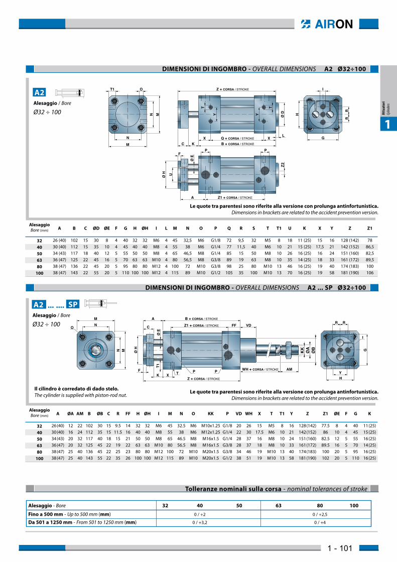
26 (40) 102 15 30 8 4 40 32 32 M6 4 45 32,5 M6 G1/8 72 9,5 32 M5 8 18 11 (25) 15 16 128 (142) 78 30 (40) 112 15 35 10 4 45 40 40 M8 4 55 38 M6 G1/4 77 11,5 40 M6 10 21 15 (25) 17,5 21 142 (152) 86,5 34 (43) 117 18 40 12 5 55 50 50 M8 4 65 46,5 M8 G1/4 85 15 50 M8 10 26 16 (25) 16 24 151 (160) 82,5 36 (47) 125 22 45 16 5 70 63 63 M10 4 80 56,5 M8 G3/8 89 19 63 M8 10 35 14 (25) 18 33 161 (172) 89,5 38 (47) 136 22 45 20 5 95 80 80 M12 4 100 72 M10 G3/8 98 25 80 M10 13 46 16 (25) 19 40 174 (183) 100 38 (47) 143 22 55 20 5 110 100 100 M12 4 115 89 M10 G1/2 105 35 100 M10 13 70 16 (25) 19 58 181 (190) 106
DIMENSIONI DI INGOMBRO - OVERALL DIMENSIONS A2 Ø32÷100
OT1
MN Y Y Ø D
RR
T T
Z + CORSA / STROKE
C KX Q + CORSA / STROKE
B + CORSA / STROKE
XL
I
Ø H
H
U
F
Ø E
Z1 + CORSA / STROKEA
P
Z2
PM
N G
Le quote tra parentesi sono riferite alla versione con prolunga antinfortunistica.Dimensions in brackets are related to the accident prevention version.
Ø H G
H
T1
C
A
XKF WH + CORSA / STROKE AM
Ø E
Z1 + CORSA / STROKE FF VD
B + CORSA / STROKE
Z + CORSA / STROKE
T
NM
O
N M
P Y
RR
I
KK
ØA
ØB
P
DIMENSIONI DI INGOMBRO - OVERALL DIMENSIONS A2 ... SP Ø32÷100
Alesaggio Bore (mm)
32 40 50 63 80 100
A ØA AM B ØB C R FF H ØH I M N O KK P VD WH X T T1 Y Z Z1 ØE F G K
26 (40) 12 22 102 30 15 9.5 14 32 32 M6 45 32.5 M6 M10x1.25 G1/8 20 26 15 M5 8 16 128 (142) 77.5 8 4 40 11 (25) 30 (40) 16 24 112 35 15 11.5 16 40 40 M8 55 38 M6 M12x1.25 G1/4 22 30 17.5 M6 10 21 142 (152) 86 10 4 45 15 (25) 34 (43) 20 32 117 40 18 15 21 50 50 M8 65 46.5 M8 M16x1.5 G1/4 28 37 16 M8 10 24 151 (160) 82.5 12 5 55 16 (25) 36 (47) 20 32 125 45 22 19 22 63 63 M10 80 56.5 M8 M16x1.5 G3/8 28 37 18 M8 10 33 161 (172) 89.5 16 5 70 14 (25) 38 (47) 25 40 136 45 22 25 23 80 80 M12 100 72 M10 M20x1.5 G3/8 34 46 19 M10 13 40 174 (183) 100 20 5 95 16 (25) 38 (47) 25 40 143 55 22 35 26 100 100 M12 115 89 M10 M20x1.5 G1/2 38 51 19 M10 13 58 181 (190) 102 20 5 110 16 (25)
Le quote tra parentesi sono riferite alla versione con prolunga antinfortunistica.Dimensions in brackets are related to the accident prevention version.
Il cilindro è corredato di dado stelo.The cylinder is supplied with piston-rod nut.
Alesaggio / Bore
Ø32 ÷ 100
A2
Alesaggio / Bore
Ø32 ÷ 100
A2 ....... SP
Alesaggio - Bore 32 40 50 63 80 100
Fino a 500 mm - Up to 500 mm (mm) 0 / +2 0 / +2,5
Da 501 a 1250 mm - From 501 to 1250 mm (mm) 0 / +3,2 0 / +4
Tolleranze nominali sulla corsa - nominal tolerances of stroke

1 - 102
Tutti gli accessori che possono essere montati su questi attuatori sono gli stessi dei cilindri a norma ISO 15552 (con lo stesso codice di ordinazione) ad eccezione di quelli riportati nella seguente tabella.All the accessories that you can utilize on this cylinder are the same of ISO 15552 version (they have the same order code). The accessories into the table below are different to ISO 15552 accessories., so they have a different order code.
Nota: Non è previsto il montaggio della cerniera femmina CA...Note: CA... front female hinge is not available for cylinders series A2, A3
Ø 63
Ø 80
Ø 100
Ø 50
Ø 63
FV.063.A2
FV.080.A2
FV.100.A2
FV.050.A3
FV.063.A3
FV ...
PB.063.A2
PB.080.A2
PB.100.A2
PB.050.A3
PB.063.A3
PB ...
Alesaggio Bore (mm)
A3
A2
ACCESSORI CILINDRI A2 ed A3 - A2 AND A3 CYLINDERS ACCESSORIES
A3 Ø32÷63 DIMENSIONI DI INGOMBRO - OVERALL DIMENSIONS
R2
30° R1
T1
C
A
LX
Ø E Q + CORSA / STROKE
Z1 + CORSA / STROKE FFB + CORSA / STROKE
Z + CORSA / STROKE
T
P
Y
NM
O
N MP
I
RRØ
H G
HXK
F
Alesaggio Bore (mm)
32 40 50 63
A B C H ØH I L M N O P Q R R1 R2 T T1 X Y Z ØE G K Z1 FF F
26 (40) 102 15 32 32 M6 4 45 32.5 M6 G1/8 72 8.7 10 5 M6 8 15 16 128 (142) 8 40 11 (25) 69.6 14 4 30 (40) 112 15 40 40 M6 4 55 38 M6 G1/4 77 10.8 12.5 6.3 M6 8 17.5 21 142 (152) 12 45 15 (25) 81 15.5 4 34 (43) 122 18 50 50 M8 4 65 46.5 M8 G1/4 90 13.4 15.5 7.8 M8 8 16 24 156 (165) 12 55 16 (25) 82 21 5 36 (47) 125 22 63 63 M10 4 80 56.5 M8 G3/8 89 15.2 19 9.5 M10 10 18 33 161 (172) 16 70 14 (25) 79.5 22 5
Le quote tra parentesi sono riferite alla versione con prolunga antinfortunistica.Dimensions in brackets are related to the accident prevention version.
Alesaggio Bore (mm)
32 40 50 63
A ØA AM B ØB C FF H ØH I M N O KK P Q R R1 R2 VD WH X T T1 Y Z Z1 ØE F G K
26 (40) 12 22 102 30 15 14 32 32 M6 45 32.5 M6 M10x1.25 G1/8 72 8.7 10 5 20 26 15 M6 8 16 128 (142) 69.6 8 4 40 11 (25) 30 (40) 16 24 112 35 15 15,5 40 40 M8 55 38 M6 M12x1.25 G1/4 77 10.8 12.5 6.3 22 30 17.5 M6 8 21 142 (152) 81 12 4 45 15 (25) 34 (43) 20 32 122 40 18 21 50 50 M8 65 46.5 M8 M16x1.5 G1/4 90 13.4 15.5 7.8 28 37 16 M8 8 24 151 (160) 82 12 5 55 16 (25) 36 (47) 20 32 125 45 22 22 63 63 M10 80 56.5 M8 M16x1.5 G3/8 89 15.2 19 9.5 28 37 18 M8 10 33 161 (172) 79.5 16 5 70 14 (25)
A3 ... SP Ø32÷63 DIMENSIONI DI INGOMBRO - OVERALL DIMENSIONS
WH + CORSA / STROKE AMK
KØ
AØ
BR2
30° R1C
A
Ø E Q + CORSA / STROKE
Z1 + CORSA / STROKE FF VDB + CORSA / STROKE
Z + CORSA / STROKE
P
P
I
RRØ
H
XKF
Y
NM
O
N M
T T1 XT
G
H
Le quote tra parentesi sono riferite alla versione con prolunga antinfortunistica.Dimensions in brackets are related to the accident prevention version.
Il cilindro è corredato di dado stelo.The cylinder is supplied with piston-rod nut.
Alesaggio / Bore
Ø32 ÷ 63
A3 ....... SP
Alesaggio / Bore
Ø32 ÷ 63
A3
Alesaggio - Bore 32 40 50 63
Fino a 500 mm - Up to 500 mm (mm) 0 / +2 0 / +2,5
Da 501 a 1250 mm - From 501 to 1250 mm (mm) 0 / +3,2 0 / +4
Tolleranze nominali sulla corsa - nominal tolerances of stroke