
Sistemi di protezione e monitoraggio Protection ... - Wattsud · [email protected] Tel.:...
36
Sistemi di protezione e monitoraggio Protection and monitoring systems
Transcript of Sistemi di protezione e monitoraggio Protection ... - Wattsud · [email protected] Tel.:...

Sistemi di protezione e monitoraggioProtection and monitoring systems

Il presente catalogo è il risultato di un accordo commerciale della WATTSUD Lavorazioni Elettromeccaniche di Precisione S.p.A. con la CPT Engineering S.r.l., azienda leader nella progettazione, produzione e assistenza di sistemi di misura e controllo per l’automazione industriale.Tale accordo di partnership prevede che la Wattsud commercializzi sia sul territorio nazionale che sui mercati esteri i prodotti progettati e prodotti dalla CPT Engineering e pubblicati sul presente catalogo.Eventuali richieste di offerta potranno essere inviate ai seguenti indirizzi di posta elettronica:
[email protected].: +39.081.7050311Fax.: +39-081.7050327Ed. dic. 2009
The following catalogue is the result of a commercial agreement between WATTSUD Lavorazioni Elettromeccaniche di Precisione S.p.A. and CPT Engine-ering S.r.l., a company leader in the design, production and assistence of con-trol and measure systems for the industrial automation.Such partnership agreement establishes that Wattsud commercialises on the National territory as well as abroad the products designed and produced by CPT Engineering and published on this catalogue.Some eventual offer requests could be sent to the following email addresses:
[email protected].: +39.081.7050311Fax.: +39-081.7050327Ed. dec. 2009
4
INDEX
Protection relay for MV lines DPL-M01
Protection and monitoring panel for MV lines DV901
Directional fault and voltage loss detector RGDAT-I
Overcurrent earth fault relay DV926
Protection and monitoring panel for MV phasing DV910
Protection and monitoring panel for Transformer HV side DV920
Protection and monitoring panel for neutral forming transformer DV922
Protection and monitoring panel for Transformer MV side DV925
Protection and monitoring panel for voltage control DV933
Protection and monitoring panel for HV line control DV945
Primary substation monitoring device DV928
Data fault recorder for primary substation DV947
Current data logger for LV lines µRECORDER CM/CT
Voltage data logger for LV lines µRECORDER TM/TT
Remote terminal unit for control and automation with RTU functions UC360
5
INDICE
Relè di protezione per reti MT DPL-M01
Pannello di protezione e controllo linea MT DV901
Dispositivo rilevatore di guasto direzionale e di presenza tensione RGDAT-I
Relè di massima corrente omopolare DV926
Pannello di protezione e controllo rifasamento MT DV910
Pannello di protezione e controllo trasformatore lato AT DV920
Pannello di protezione e controllo trasformatore formatore di neutro DV922
Pannello di protezione e controllo trasformatore lato MT DV925
Pannello di protezione e controllo regolazione della tensione DV933
Pannello di protezione e controllo regolazione linea AT DV945
Dispositivo di monitoraggio di cabina primaria DV928
Oscilloperturbografo per cabina primaria DV947
Datalogger di corrente per rete BT μRECORDER CM/CT
Datalogger di tensione per rete BT μRECORDER TM/TT
Unità periferica di controllo e automazione con funzioni RTU UC360
6
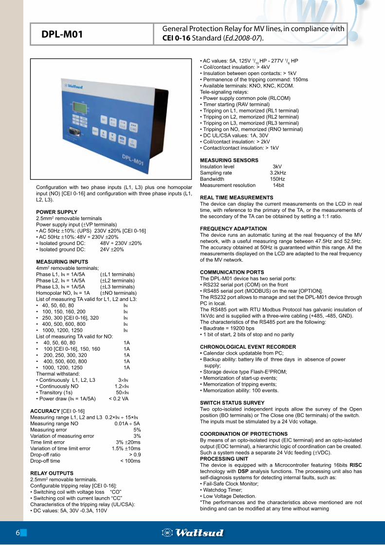
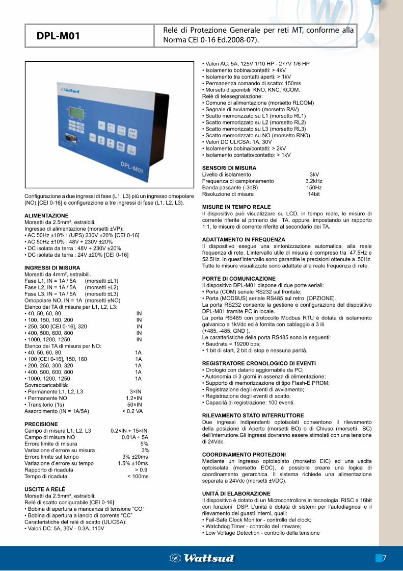
DPL-M01General Protection Relay for MV lines, in compliance with CEI 0-16 Standard (Ed.2008-07).
Configuration with two phase inputs (L1, L3) plus one homopolar input (NO) [CEI 0-16] and configuration with three phase inputs (L1, L2, L3).
POWER SUPPLY2.5mm2 removable terminalsPower supply input (±VP terminals)• AC 50Hz ±10%: (UPS) 230V ±20% [CEI 0-16]• AC 50Hz ±10%: 48V ÷ 230V ±20%• Isolated ground DC: 48V ÷ 230V ±20%• Isolated ground DC: 24V ±20%
MEASURING INPUTS4mm2 removable terminals;Phase L1, In = 1A/5A (±L1 terminals)Phase L2, In = 1A/5A (±L2 terminals)Phase L3, In = 1A/5A (±L3 terminals)Homopolar NO, In = 1A (±NO terminals)List of measuring TA valid for L1, L2 and L3:• 40, 50, 60, 80 In• 100, 150, 160, 200 In• 250, 300 [CEI 0-16], 320 In• 400, 500, 600, 800 In• 1000, 1200, 1250 InList of measuring TA valid for NO:• 40, 50, 60, 80 1A• 100 [CEI 0-16], 150, 160 1A• 200, 250, 300, 320 1A• 400, 500, 600, 800 1A• 1000, 1200, 1250 1AThermal withstand:• Continuously L1, L2, L3 3×In• Continuously NO 1.2×In• Transitory (1s) 50×In• Power draw (In = 1A/5A) < 0.2 VA
ACCURACY [CEI 0-16]Measuring range L1, L2 and L3 0.2×In ÷ 15×In Measuring range NO 0.01A ÷ 5AMeasuring error 5% Variation of measuring error 3%Time limit error 3% ±20msVariation of time limit error 1.5% ±10msDrop-off ratio > 0.9Drop-off time < 100ms
RELAY OUTPUTS2.5mm2 removable terminals.Configurable tripping relay [CEI 0-16]:• Switching coil with voltage loss “CO”• Switching coil with current launch “CC”Characteristics of the tripping relay (UL/CSA):• DC values: 5A, 30V -0.3A, 110V
• AC values: 5A, 125V 1/10
HP - 277V 1/6 HP
• Coil/contact insulation: > 4kV• Insulation between open contacts: > 1kV• Permanence of the tripping command: 150ms• Available terminals: KNO, KNC, KCOM.Tele-signaling relays:• Power supply common pole (RLCOM)• Timer starting (RAV terminal)• Tripping on L1, memorized (RL1 terminal)• Tripping on L2, memorized (RL2 terminal)• Tripping on L3, memorized (RL3 terminal)• Tripping on NO, memorized (RNO terminal)• DC UL/CSA values: 1A, 30V• Coil/contact insulation: > 2kV• Contact/contact insulation: > 1kV
MEASURING SENSORSInsulation level 3kVSampling rate 3.2kHzBandwidth 150HzMeasurement resolution 14bit
REAL TIME MEASUREMENTSThe device can display the current measurements on the LCD in real time, with reference to the primary of the TA, or the measurements of the secondary of the TA can be obtained by setting a 1:1 ratio.
FREQUENCY ADAPTATIONThe device runs an automatic tuning at the real frequency of the MV network, with a useful measuring range between 47.5Hz and 52.5Hz. The accuracy obtained at 50Hz is guaranteed within this range. All the measurements displayed on the LCD are adapted to the real frequency of the MV network.
COMMUNICATION PORTSThe DPL-M01 device has two serial ports:• RS232 serial port (COM) on the front• RS485 serial port (MODBUS) on the rear [OPTION].The RS232 port allows to manage and set the DPL-M01 device through PC in local.The RS485 port with RTU Modbus Protocol has galvanic insulation of 1kVdc and is supplied with a three-wire cabling (+485, -485, GND). The characteristics of the RS485 port are the following:• Baudrate = 19200 bps• 1 bit of start, 2 bits of stop and no parity
CHRONOLOGICAL EVENT RECORDER• Calendar clock updatable from PC;• Backup ability: battery life of three days in absence of power supply;• Storage device type Flash-E2PROM;• Memorization of start-up events;• Memorization of tripping events;• Memorization ability: 100 events.
SWITCH STATUS SURVEYTwo opto-isolated independent inputs allow the survey of the Open position (BO terminals) or The Close one (BC terminals) of the switch.The inputs must be stimulated by a 24 Vdc voltage.
COORDINATION OF PROTECTIONSBy means of an opto-isolated input (EIC terminal) and an opto-isolated output (EOC terminal), a hierarchic logic of coordination can be created. Such a system needs a separate 24 Vdc feeding (±VDC).PROCESSING UNITThe device is equipped with a Microcontroller featuring 16bits RISC technology with DSP analysis functions. The processing unit also has self-diagnosis systems for detecting internal faults, such as:• Fail-Safe Clock Monitor;• Watchdog Timer; • Low Voltage Detection.*The performances and the characteristics above mentioned are not binding and can be modified at any time without warning
Configurazione a due ingressi di fase (L1, L3) più un ingresso omopolare (NO) [CEI 0-16] e configurazione a tre ingressi di fase (L1, L2, L3).
ALIMENTAZIONEMorsetti da 2.5mm², estraibili.Ingresso di alimentazione (morsetti ±VP):• AC 50Hz ±10% : (UPS) 230V ±20% [CEI 0-16]• AC 50Hz ±10% : 48V ÷ 230V ±20%• DC isolata da terra : 48V ÷ 230V ±20%• DC isolata da terra : 24V ±20% [CEI 0-16]
INGRESSI DI MISURAMorsetti da 4mm², estraibili.Fase L1, IN = 1A / 5A (morsetti ±L1)Fase L2, IN = 1A / 5A (morsetti ±L2)Fase L3, IN = 1A / 5A (morsetti ±L3)Omopolare NO, IN = 1A (morsetti ±NO)Elenco dei TA di misura per L1, L2, L3:• 40, 50, 60, 80 IN• 100, 150, 160, 200 IN• 250, 300 [CEI 0-16], 320 IN• 400, 500, 600, 800 IN• 1000, 1200, 1250 INElenco dei TA di misura per NO:• 40, 50, 60, 80 1A• 100 [CEI 0-16], 150, 160 1A• 200, 250, 300, 320 1A• 400, 500, 600, 800 1A• 1000, 1200, 1250 1ASovraccaricabilità:• Permanente L1, L2, L3 3×IN• Permanente NO 1.2×IN• Transitorio (1s) 50×INAssorbimento (IN = 1A/5A) < 0.2 VA
PRECISIONE Campo di misura L1, L2, L3 0.2×IN ÷ 15×INCampo di misura NO 0.01A ÷ 5AErrore limite di misura 5%Variazione d’errore su misura 3%Errore limite sul tempo 3% ±20msVariazione d’errore su tempo 1.5% ±10msRapporto di ricaduta > 0.9Tempo di ricaduta < 100ms
USCITE A RELÉMorsetti da 2.5mm², estraibili.Relé di scatto conigurabile [CEI 0-16]:• Bobina di apertura a mancanza di tensione “CO”• Bobina di apertura a lancio di corrente “CC”Caratteristiche del relé di scatto (UL/CSA):• Valori DC: 5A, 30V - 0.3A, 110V
• Valori AC: 5A, 125V 1/10 HP - 277V 1/6 HP• Isolamento bobina/contatti: > 4kV• Isolamento tra contatti aperti: > 1kV• Permanenza comando di scatto: 150ms• Morsetti disponibili: KNO, KNC, KCOM.Relé di telesegnalazione:• Comune di alimentazione (morsetto RLCOM)• Segnale di avviamento (morsetto RAV)• Scatto memorizzato su L1 (morsetto RL1)• Scatto memorizzato su L2 (morsetto RL2)• Scatto memorizzato su L3 (morsetto RL3)• Scatto memorizzato su NO (morsetto RNO)• Valori DC UL/CSA: 1A, 30V• Isolamento bobina/contatti: > 2kV• Isolamento contatto/contatto: > 1kV
SENSORI DI MISURALivello di isolamento 3kVFrequenza di campionamento 3.2kHzBanda passante (-3dB) 150HzRisoluzione di misura 14bit
MISURE IN TEMPO REALEIl dispositivo può visualizzare su LCD, in tempo reale, le misure di corrente riferite al primario dei TA, oppure, impostando un rapporto 1:1, le misure di corrente riferite al secondario dei TA.
ADATTAMENTO IN FREQUENZAIl dispositivo esegue una sintonizzazione automatica, alla reale frequenza di rete. L’intervallo utile di misura è compreso tra 47.5Hz e 52.5Hz. In quest’intervallo sono garantite le precisioni ottenute a 50Hz.Tutte le misure visualizzate sono adattate alla reale frequenza di rete.
PORTE DI COMUNICAZIONEIl dispositivo DPL-M01 dispone di due porte seriali: • Porta (COM) seriale RS232 sul frontale;• Porta (MODBUS) seriale RS485 sul retro [OPZIONE].La porta RS232 consente la gestione e configurazione del dispositivo DPL-M01 tramite PC in locale.La porta RS485 con protocollo Modbus RTU è dotata di isolamento galvanico a 1kVdc ed è fornita con cablaggio a 3 ili(+485, -485, GND ).Le caratteristiche della porta RS485 sono le seguenti:• Baudrate = 19200 bps; • 1 bit di start, 2 bit di stop e nessuna parità.
REGISTRATORE CRONOLOGICO DI EVENTI• Orologio con datario aggiornabile da PC;• Autonomia di 3 giorni in assenza di alimentazione;• Supporto di memorizzazione di tipo Flash-E PROM;• Registrazione degli eventi di avviamento;• Registrazione degli eventi di scatto;• Capacità di registrazione: 100 eventi.
RILEVAMENTO STATO INTERRUTTOREDue ingressi indipendenti optoisolati consentono il rilevamento della posizione di Aperto (morsetti BO) o di Chiuso (morsetti BC) dell’interruttore.Gli ingressi dovranno essere stimolati con una tensione di 24Vdc.
COORDINAMENTO PROTEZIONIMediante un ingresso optoisolato (morsetto EIC) ed una uscita optoisolata (morsetto EOC), è possibile creare una logica di coordinamento gerarchica. Il sistema richiede una alimentazione separata a 24Vdc (morsetti ±VDC).
UNITÁ DI ELABORAZIONEIl dispositivo è dotato di un Microcontrollore in tecnologia RISC a 16bit con funzioni DSP. L’unità è dotata di sistemi per l’autodiagnosi e il rilevamento dei guasti interni, quali:• Fail-Safe Clock Monitor - controllo del clock;• Watchdog Timer - controllo del irmware;• Low Voltage Detection - controllo della tensione
DPL-M01Relé di Protezione Generale per reti MT, conforme alla Norma CEI 0-16 Ed.2008-07).
7
8
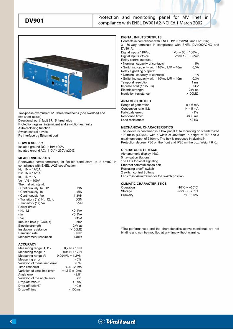
Two-phase overcurrent 51, three thresholds (one overload and two short-circuit)Directional earth fault 67, 5 thresholdsProtection against intermittent and evolutionary faultsAuto-reclosing functionSwitch control devicePc interface by Ethernet port
POWER SUPPLYIsolated ground DC: 110V ±20%Isolated ground AC: 110V ÷ 230V ±20%.
MEASURING INPUTSRemovable screw terminals, for flexible conductors up to 4mm2, in compliance with ENEL LV27 specification.I4, IN = 1A/5AI12, IN = 1A/5AIo, IN = 1AVo VN = 100VThermal withstand:• Continuously I4, I12 3IN• Continuously Io 5IN• Continuously Vo 1,3VN• Transitory (1s) I4, I12, Io 50IN• Transitory (1s) Vo 2VNPower draw:• I4, I12 <0,1VA• Io <0,1VA• Vo <1VAImpulse hold (1,2/50µs) 5kVElectric strength 2kV acInsulation resistance >100MΩSampling rate 8kHzMeasurement resolution 14bits
ACCURACYMeasuring range I4, I12 0,2IN ÷ 18INMeasuring range Io 0,005IN ÷ 12INMeasuring range Vo 0,004VN ÷ 1,2VNMeasuring error <5% Variation of measuring error <3%Time limit error <3% ±20msVariation of time limit error <1.5% ±10msAngle error <2,5°Variation of the angle error <5°Drop-off ratio 51 >0,95Drop-off ratio 67 >0,9Drop-off time <100ms
DIGITAL INPUTS/OUTPUTSContacts in compliance with ENEL DV1002A2NC and DV801A;3 50-way terminals in compliance with ENEL DV1002A2NC and DV801A;Digital inputs 110Vcc Von= 80 ÷ 160VccDigital inputs 24Vcc Von= 19 ÷ 35VccRelay control outputs:• Nominal capacity of contacts 5A• Switching capacity with 110Vcc L/R = 40m 0,5ARelay signalling outputs:• Nominal capacity of contacts 1A• Switching capacity with 110Vcc L/R = 40m 0,3ATemporal resolution 1 msImpulse hold (1,2/50µs) 5kVElectric strength 2kV acInsulation resistance >100MΩ
ANALOGIC OUTPUTRange of generation: 0 ÷ 6 mAConversion ratio I12: IN = 5 mAFull-scale error: <1%Response time: <300 msLoad resistance: <2 kΩ
MECHANICAL CHARACTERISTICS The device is contained in a box panel fit to mounting on standardized 19’’ racks (CEI/48), with a width of 482.6mm, a height of 3U, and a maximum depth of 310mm. The box is produced in aluzinc®. Protection degree IP30 on the front and IP20 on the box. Weight 6 Kg.
OPERATOR INTERFACEAlphanumeric display 16x25 navigation Buttons15 LEDs for local signalingEthernet communication portReclosing on/off switch 2 switch control ButtonsLed cross visualization for the switch position
CLIMATIC CHARACTERISTICSOperation -10°C ÷ +55°CStorage -25°C ÷ +70°CHumidity 5% ÷ 95%
*The performances and the characteristics above mentioned are not binding and can be modified at any time without warning.
DV901Protection and monitoring panel for MV lines in compliance with ENEL DV901A2-NCI Ed.1 March 2002.
9
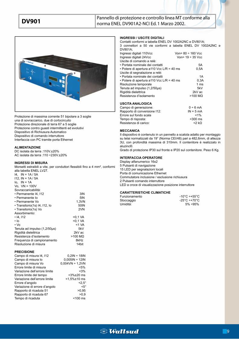
Protezione di massima corrente 51 bipolare a 3 soglie una di sovraccarico, due di cortocircuitoProtezione direzionale di terra 67 a 5 soglieProtezione contro guasti intermittenti ed evolutiviDispositivo di Richiusura AutomaticoDispositivo di comando interruttoreInterfaccia con PC tramite porta Ethernet
ALIMENTAZIONEDC isolata da terra :110V.±20%AC isolata da terra :110 ÷230V.±20%
INGRESSI DI MISURAMorsetti estraibili a vite, per conduttori flessibili fino a 4 mm², conformi alla tabella ENEL LV27.I4, IN = 1A / 5A I12, IN = 1A / 5AIo, IN = 1A Vo, VN = 100V Sovraccaricabilità:• Permanente I4, I12 3IN• Permanente Io 5IN• Permanente Vo 1,3VN• Transitorio(1s) I4, I12, Io 50IN• Transitorio(1s) Vo 2VNAssorbimento:• I4, I12 <0,1 VA• Io <0,1 VA• Vo <1 VATenuta ad impulso (1,2/50µs) 5kVRigidità dielettrica 2kV acResistenza d’isolamento >100 MΩFrequenza di campionamento 8kHzRisoluzione di misura 14bit
PRECISIONE Campo di misura I4, I12 0,2IN ÷ 18INCampo di misura Io 0,005IN ÷ 12INCampo di misura Vo 0,004VN ÷ 1,2VNErrore limite di misura <5%Variazione dell’errore limite <3%Errore limite del tempo <3%±20 msVariazione dell’errore limite <1,5%±10 msErrore d’angolo <2,5°Variazione di errore d’angolo <5°Rapporto di ricaduta 51 >0,95Rapporto di ricaduta 67 >0,9Tempo di ricaduta <100 ms
INGRESSI / USCITE DIGITALIContatti conformi a tabella ENEL DV 1002A2NC e DV801A;3 connettori a 50 vie conformi a tabella ENEL DV 1002A2NC e DV801A;Ingressi digitali 110Vcc Von= 80 ÷ 160 VccIngressi digitali 24Vcc Von= 19 ÷ 35 VccUscite di comando a relè: • Portata nominale dei contatti 5A• Potere di apertura a110 Vcc L/R = 40 ms 0,5AUscite di segnalazione a relè:• Portata nominale dei contatti 1A• Potere di apertura a110 Vcc L/R = 40 ms 0,3ARisoluzione temporale 1 msTenuta ad impulso (1,2/50µs) 5kVRigidità dielettrica 2kV acResistenza d’isolamento >100 MΩ
USCITA ANALOGICACampo di generazione: 0 ÷ 6 mARapporto di conversione I12: IN = 5 mAErrore sul fondo scala <1%Tempo di risposta: <300 msResistenza di carico: <2 kΩ
MECCANICAIl dispositivo è contenuto in un pannello a scatola adatto per montaggio su telai normalizzati da 19” (Norma CEI/48) pari a 482,6mm, di altezza 3U, con profondità massima di 310mm. Il contenitore è realizzato in aluzinc®.Grado di protezione IP30 sul fronte e IP20 sul contenitore. Peso 6 Kg.
INTERFACCIA OPERATOREDisplay alfanumerico 16x25 Pulsanti di navigazione15 LED per segnalazioni localiPorta di comunicazione EthernetCommutatore inclusione / esclusione richiusura2 Pulsanti comando interruttoreLED a croce di visualizzazione posizione interruttore
CARATTERISTICHE CLIMATICHEFunzionamento -10°C ÷+55°CStoccaggio -25°C ÷+70°CUmidità: 5% ÷95%
DV901Pannello di protezione e controllo linea MT conforme alla norma ENEL DV901A2-NCI Ed. 1 Marzo 2002.
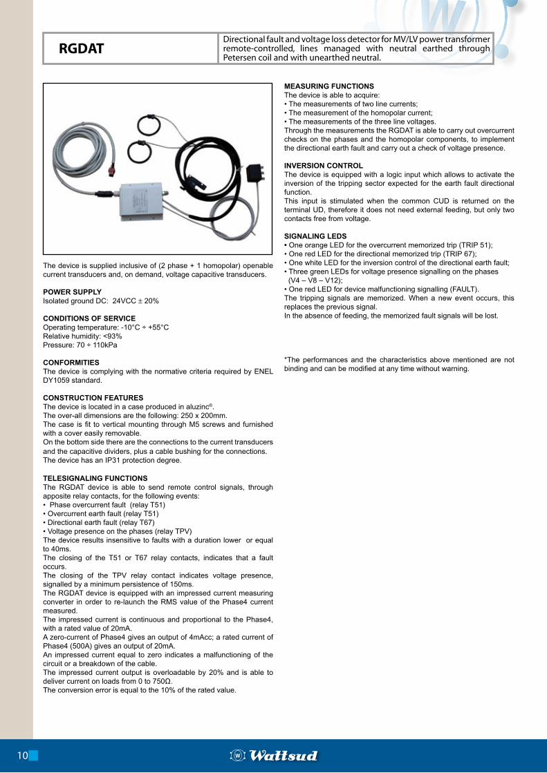
The device is supplied inclusive of (2 phase + 1 homopolar) openable current transducers and, on demand, voltage capacitive transducers.
POWER SUPPLYIsolated ground DC: 24VCC ± 20%
CONDITIONS OF SERVICEOperating temperature: -10°C ÷ +55°CRelative humidity: <93%Pressure: 70 ÷ 110kPa
CONFORMITIESThe device is complying with the normative criteria required by ENEL DY1059 standard.
CONSTRUCTION FEATURESThe device is located in a case produced in aluzinc®.The over-all dimensions are the following: 250 x 200mm.The case is fit to vertical mounting through M5 screws and furnished with a cover easily removable.On the bottom side there are the connections to the current transducers and the capacitive dividers, plus a cable bushing for the connections.The device has an IP31 protection degree.
TELESIGNALING FUNCTIONSThe RGDAT device is able to send remote control signals, through apposite relay contacts, for the following events:• Phase overcurrent fault (relay T51)• Overcurrent earth fault (relay T51)• Directional earth fault (relay T67)• Voltage presence on the phases (relay TPV)The device results insensitive to faults with a duration lower or equal to 40ms.The closing of the T51 or T67 relay contacts, indicates that a fault occurs.The closing of the TPV relay contact indicates voltage presence, signalled by a minimum persistence of 150ms.The RGDAT device is equipped with an impressed current measuring converter in order to re-launch the RMS value of the Phase4 current measured.The impressed current is continuous and proportional to the Phase4, with a rated value of 20mA.A zero-current of Phase4 gives an output of 4mAcc; a rated current of Phase4 (500A) gives an output of 20mA.An impressed current equal to zero indicates a malfunctioning of the circuit or a breakdown of the cable.The impressed current output is overloadable by 20% and is able to deliver current on loads from 0 to 750Ω.The conversion error is equal to the 10% of the rated value.
MEASURING FUNCTIONSThe device is able to acquire:• The measurements of two line currents;• The measurement of the homopolar current;• The measurements of the three line voltages.Through the measurements the RGDAT is able to carry out overcurrent checks on the phases and the homopolar components, to implement the directional earth fault and carry out a check of voltage presence.
INVERSION CONTROLThe device is equipped with a logic input which allows to activate the inversion of the tripping sector expected for the earth fault directional function. This input is stimulated when the common CUD is returned on the terminal UD, therefore it does not need external feeding, but only two contacts free from voltage.
SIGNALING LEDS• One orange LED for the overcurrent memorized trip (TRIP 51);• One red LED for the directional memorized trip (TRIP 67);• One white LED for the inversion control of the directional earth fault;• Three green LEDs for voltage presence signalling on the phases (V4 – V8 – V12);• One red LED for device malfunctioning signalling (FAULT).The tripping signals are memorized. When a new event occurs, this replaces the previous signal.In the absence of feeding, the memorized fault signals will be lost.
*The performances and the characteristics above mentioned are not binding and can be modified at any time without warning.
10
RGDATDirectional fault and voltage loss detector for MV/LV power transformer remote-controlled, lines managed with neutral earthed through Petersen coil and with unearthed neutral.

Il dispositivo viene fornito completo di trasduttori di corrente apribili (2 di fase + 1 omopolare) e a richiesta di trasduttori capacitivi di tensione.
ALIMENTAZIONEDC isolata da terra : 24Vcc ± 20%
CONDIZIONI DI SERVIZIOTemperatura di funzionamento: -10 °C ÷ +55 °CUmidità relativa : < 93%.Pressione atmosferica: 70 ÷ 110 kPa.
CONFORMITÁIl dispositivo è conforme ai criteri normativi richiesti dalla Tabella Unifi-cata ENEL DY1059.
CARATTERISTICHE COSTRUTTIVEIl dispositivo è alloggiato in un contenitore realizzato in lamiera ALUZINC.Le dimensioni di ingombro sono le seguenti: 250 x 200mm.Il contenitore è adatto al fissaggio verticale mediante viti M5 ed è munito di coperchio facilmente asportabile.Sul lato inferiore sono presenti le connessioni verso i trasduttori di corrente e i partitori capacitivi, più un passacavo per le connessioni.Il dispositivo è dotato di un grado di protezione IP31.
FUNZIONI DI TELESEGNALAZIONEIl dispositivo RGDAT è in grado di segnalare in remoto, mediante opportuni contatti a relé, i seguenti eventi:• guasto per massima corrente di fase (relé T51);• guasto per massima corrente di terra (relé T51);• guasto direzionale di terra (relé T67);• presenza tensione sulle fasi (relé TPV).Il dispositivo risulta insensibile ai guasti con durata inferiore o uguale a 40ms.La chiusura dei contatti a relé T51 o T67 indica il verificarsi di un guasto.La chiusura del contatto a relé TPV indica la presenza tensione, segnalata con una persistenza minima di 150ms.Il dispositivo RGDAT è dotato di un convertitore di misura a corrente impressa per rilanciare il valore RMS della corrente di Fase4 misurata.La corrente impressa è continua e proporzionale alla Fase4, con valore nominale di 20mA.Per corrente di Fase4 nulla, si hanno 4mAcc di uscita; per corrente di Fase4 nominale (500A) si hanno 20mA.Una corrente impressa pari a zero indica un malfunzionamento del circuito o un’interruzione del cavo.L’uscita a corrente impressa è sovraccaricabile del 20% e può erogare corrente su carichi che vanno da zero a 750Ω.L’errore di conversione è pari al 10% sul valore nominale.
FUNZIONI DI MISURAIl dispositivo è in grado di acquisire:• le misure di due correnti di linea;• la misura della corrente omopolare;• le misure delle tre tensioni di linea.Attraverso le misure il modulo RGDAT è in grado di eseguire controlli di massima corrente sulle fasi e sulle componenti omopolari, di imple-mentare la protezione direzionale di terra e di eseguire in controllo di presenza tensione.
COMANDO DI INVERSIONEIl dispositivo è dotato di un ingresso logico che consente di attivare l’inversione del settore d’intervento previsto per la funzione direzionale di terra.Questo ingresso è stimolato quando il comune CUD viene riportato su morsetto UD, dunque non necessita di alimentazione esterna, ma solo di due contatti liberi da tensione.
LED DI SEGNALAZIONE• un LED di colore arancio per la segnalazione di intervento memoriz-zato a massima corrente (SCATTO 51);• un LED di colore rosso per la segnalazione di intervento memorizza-to di tipo direzionale (SCATTO 67);• un LED di colore bianco per segnalare il comando di inversione della protezione direzionale di terra;• tre LED di colore verde per la segnalazione della presenza di tensio-ne sulle fasi (V4 - V8 - V12);• un LED di colore rosso per segnalare il malfunzionamento del dispo-sitivo (ANOMALIA).Le segnalazioni d’intervento vengono memorizzate.Quando si verifica un nuovo evento, questo sostituisce la precedente segnalazione.
In assenza di alimentazione, le segnalazioni memorizzate di guasto andranno perse.
Dispositivo rilevatore di guasto direzionale e di assenza tensione, per cabina secondaria MT/BT telecontrollata, e reti esercite con neutro a terra tramite bobina di Petersen e con neutro isolato.
11
RGDAT
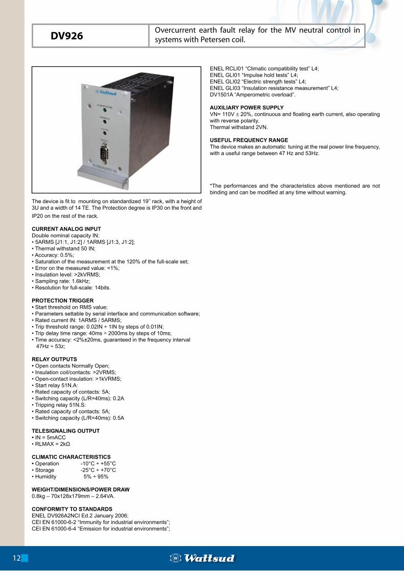
The device is fit to mounting on standardized 19’’ rack, with a height of 3U and a width of 14 TE. The Protection degree is IP30 on the front and
IP20 on the rest of the rack.
CURRENT ANALOG INPUT Double nominal capacity IN:• 5ARMS [J1:1, J1:2] / 1ARMS [J1:3, J1:2];• Thermal withstand 50 IN;• Accuracy: 0.5%;• Saturation of the measurement at the 120% of the full-scale set;• Error on the measured value: <1%;• Insulation level: >2kVRMS;• Sampling rate: 1.6kHz; • Resolution for full-scale: 14bits.
PROTECTION TRIGGER• Start threshold on RMS value;• Parameters settable by serial interface and communication software;• Rated current IN: 1ARMS / 5ARMS;• Trip threshold range: 0.02IN ÷ 1IN by steps of 0.01IN;• Trip delay time range: 40ms ÷ 2000ms by steps of 10ms;• Time accuracy: <2%±20ms, guaranteed in the frequency interval 47Hz ÷ 53z;
RELAY OUTPUTS• Open contacts Normally Open;• Insulation coil/contacts: >2VRMS;• Open-contact insulation: >1kVRMS;• Start relay 51N.A:• Rated capacity of contacts: 5A;• Switching capacity (L/R=40ms): 0.2A• Tripping relay 51N.S:• Rated capacity of contacts: 5A;• Switching capacity (L/R=40ms): 0.5A
TELESIGNALING OUTPUT• IN = 5mACC• RLMAX = 2kΩ
CLIMATIC CHARACTERISTICS• Operation -10°C ÷ +55°C• Storage -25°C ÷ +70°C• Humidity 5% ÷ 95%
WEIGHT/DIMENSIONS/POWER DRAW0.8kg – 70x128x179mm – 2.64VA.
CONFORMITY TO STANDARDSENEL DV926A2NCI Ed.2 January 2006;CEI EN 61000-6-2 “Immunity for industrial environments”;CEI EN 61000-6-4 “Emission for industrial environments”;
ENEL RCLI01 “Climatic compatibility test” L4;ENEL GLI01 “Impulse hold tests” L4;ENEL GLI02 “Electric strength tests” L4;ENEL GLI03 “Insulation resistance measurement” L4;DV1501A “Amperometric overload”.
AUXILIARY POWER SUPPLYVN= 110V ± 20%, continuous and floating earth current, also operating with reverse polarity.Thermal withstand 2VN.
USEFUL FREQUENCY RANGEThe device makes an automatic tuning at the real power line frequency, with a useful range between 47 Hz and 53Hz.
*The performances and the characteristics above mentioned are not binding and can be modified at any time without warning.
12
DV926Overcurrent earth fault relay for the MV neutral control in systems with Petersen coil.
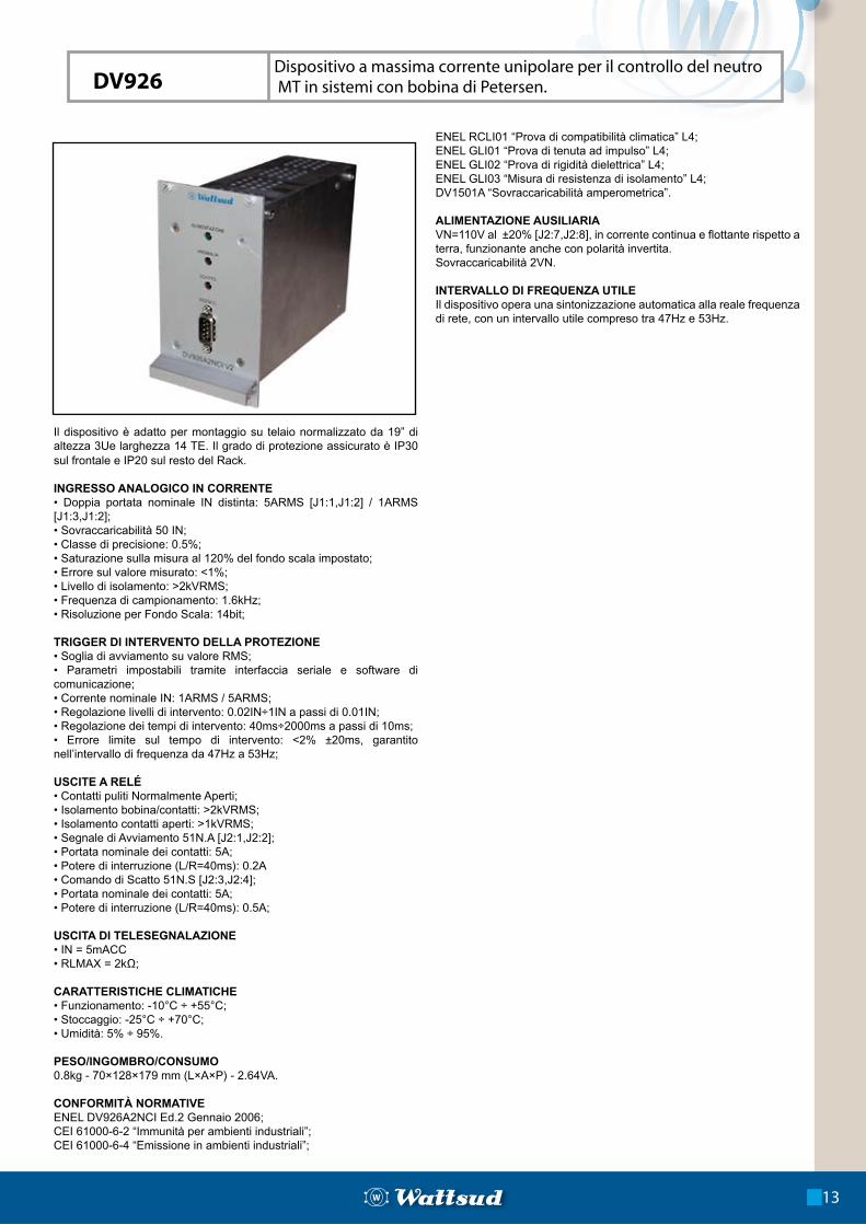
Il dispositivo è adatto per montaggio su telaio normalizzato da 19” di altezza 3Ue larghezza 14 TE. Il grado di protezione assicurato è IP30 sul frontale e IP20 sul resto del Rack. INGRESSO ANALOGICO IN CORRENTE• Doppia portata nominale IN distinta: 5ARMS [J1:1,J1:2] / 1ARMS [J1:3,J1:2];• Sovraccaricabilità 50 IN;• Classe di precisione: 0.5%;• Saturazione sulla misura al 120% del fondo scala impostato;• Errore sul valore misurato: <1%;• Livello di isolamento: >2kVRMS;• Frequenza di campionamento: 1.6kHz;• Risoluzione per Fondo Scala: 14bit;
TRIGGER DI INTERVENTO DELLA PROTEZIONE• Soglia di avviamento su valore RMS;• Parametri impostabili tramite interfaccia seriale e software di comunicazione;• Corrente nominale IN: 1ARMS / 5ARMS;• Regolazione livelli di intervento: 0.02IN÷1IN a passi di 0.01IN;• Regolazione dei tempi di intervento: 40ms÷2000ms a passi di 10ms;• Errore limite sul tempo di intervento: <2% ±20ms, garantito nell’intervallo di frequenza da 47Hz a 53Hz;
USCITE A RELÉ• Contatti puliti Normalmente Aperti;• Isolamento bobina/contatti: >2kVRMS;• Isolamento contatti aperti: >1kVRMS;• Segnale di Avviamento 51N.A [J2:1,J2:2];• Portata nominale dei contatti: 5A;• Potere di interruzione (L/R=40ms): 0.2A• Comando di Scatto 51N.S [J2:3,J2:4];• Portata nominale dei contatti: 5A;• Potere di interruzione (L/R=40ms): 0.5A;
USCITA DI TELESEGNALAZIONE• IN = 5mACC• RLMAX = 2kΩ;
CARATTERISTICHE CLIMATICHE• Funzionamento: -10°C ÷ +55°C;• Stoccaggio: -25°C ÷ +70°C;• Umidità: 5% ÷ 95%.
PESO/INGOMBRO/CONSUMO0.8kg - 70×128×179 mm (L×A×P) - 2.64VA.
CONFORMITÀ NORMATIVEENEL DV926A2NCI Ed.2 Gennaio 2006;CEI 61000-6-2 “Immunità per ambienti industriali”;CEI 61000-6-4 “Emissione in ambienti industriali”;
ENEL RCLI01 “Prova di compatibilità climatica” L4;ENEL GLI01 “Prova di tenuta ad impulso” L4;ENEL GLI02 “Prova di rigidità dielettrica” L4;ENEL GLI03 “Misura di resistenza di isolamento” L4;DV1501A “Sovraccaricabilità amperometrica”.
ALIMENTAZIONE AUSILIARIAVN=110V al ±20% [J2:7,J2:8], in corrente continua e flottante rispetto a terra, funzionante anche con polarità invertita.Sovraccaricabilità 2VN.
INTERVALLO DI FREQUENZA UTILEIl dispositivo opera una sintonizzazione automatica alla reale frequenza di rete, con un intervallo utile compreso tra 47Hz e 53Hz.
Dispositivo a massima corrente unipolare per il controllo del neutro MT in sistemi con bobina di Petersen.
13
DV926
Two-phase overcurrent 51, one thresholdDirectional earth fault 67, two thresholdsMaximum voltage protection 59VDifferential one-phase overcurrent 87PC interface via Ethernet port
POWER SUPPLYIsolated ground DC: 110V ±20%;Isolated ground AC: 110V ÷ 230V ±20%.
MEASURING INPUTSRemovable screw terminals, for flexible conductors up to 4mm2, in compliance with ENEL LV27 specification.I4, IN = 1A/5AI12, IN = 1A/5AIo, IN = 1AVo VN = 100VV 4-8, VN = 100VId, IN = 1AThermal withstand:• Continuously I4, I12, Id 3IN• Continuously Io 5IN• Continuously Vo 4-8 1 ,3VN• Transitory (1s) I4, I12, Io 50IN• Transitory (1s) Vo, V 4-8 2VNPower draw:• I4, I12 <0,1VA• Io, Id <0,1VA• Vo, V 4-8 <1VAImpulse hold (1,2/50µs) 5kVElectric strength 2kV acInsulation resistance >100MΩSampling rate 8kHzMeasurement resolution 14bits
ACCURACYMeasuring range I4, I12 0,2IN ÷ 18INMeasuring range Io 0,005IN ÷ 12INMeasuring range Vo 0,004VN ÷ 1,2VNMeasuring range V 4-8 0,8VN ÷ 1,8VN Measuring range Id 0,008IN ÷ 2,4INMeasuring error <5% Variation of measuring error <3%Time limit error <3% ±20msVariation of time limit error <1.5% ±10msAngle error <2,5°Variation of the angle error <5°Drop-off ratio 51, 87 >0,95Drop-off ratio 67 >0,9Drop-off ratio 59V >0,9Drop-off time <100ms
DIGITAL INPUTS / OUTPUTSContacts in compliance with ENEL DV1002A2NC and DV801A;3 50-way terminals in compliance with ENEL DV1002A2NC and DV801A;Digital inputs 110Vcc Von= 80 ÷ 160VccRelay control outputs:- Nominal capacity of contacts 5A- Switching capacity at 110Vcc L/R = 40m 0,5ARelay signalling outputs:- Nominal capacity of contacts 1A- Switching capacity at 110Vcc L/R = 40m 0,3ATemporal resolution 1 msImpulse hold (1,2/50µs) 5kVElectric strength 2kV acInsulation resistance >100MΩ
ANALOGIC OUTPUTSContacts in compliance with ENEL DV1002A2NC and DV801A; Range of generation: 0 ÷ 6 mAConversion ratio I12: IN = 5 mAFull-scale error: ≤1%Response time: ≤300 msLoad resistance: ≤2 kΩ
MECHANICAL CHARACTERISTICS The device is contained in a box panel fit to mounting on standardized 19’’ racks (CEI/48), with a width of 482.6mm, a height of 3U, and a maximum depth of 310mm. The box is produced in aluzinc®. Protection degree IP30 on the front and IP20 on the box. Weight 6 Kg.
OPERATOR INTERFACEAlphanumeric display 16x25 navigation Buttons15 LEDs for local signalingEthernet communication port2 switch control ButtonsLed cross visualization for switch position
CLIMATIC CHARACTERISTICSOperation -10°C ÷ +55°CStorage -25°C ÷ +70°CHumidity 5% ÷ 95%
*The performances and the characteristics above mentioned are not binding and can be modified at any time without warning.
14
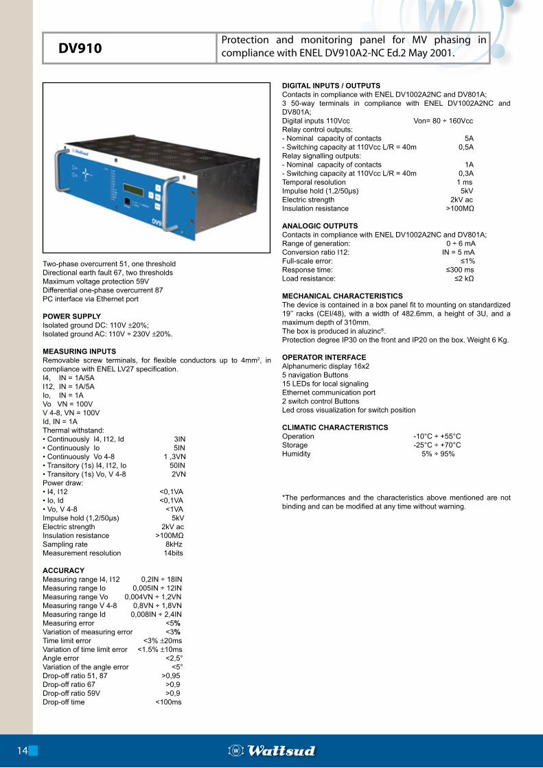
DV910Protection and monitoring panel for MV phasing in compliance with ENEL DV910A2-NC Ed.2 May 2001.
Protezione di massima corrente 51 bipolare ad una sogliaProtezione direzionale di terra 67 a 2 soglieProtezione di massima tensione 59VProtezione di massima corrente unipolare differenziale 87Interfaccia con PC tramite porta Ethernet
ALIMENTAZIONEDC isolata da terra :110V.±20%.AC isolata da terra :110 ÷230V.±20%;
INGRESSI DI MISURAMorsetti estraibili a vite, per conduttori flessibili fino a 4 mm2 conformi alla tabella ENEL LV27.I4, IN = 1A / 5A I12, IN = 1A / 5A Io, IN = 1A Vo, VN = 100V V 4-8, VN = 100V Id, IN = 1A Sovraccaricabilità:• Permanente I4, I12, Id 3IN• Permanente Io 5IN• Permanente Vo, V 4-8 1,3VN• Transitorio(1s) I4, I12, Io, Id 50IN• Transitorio(1s) Vo, V 4-8 2VNAssorbimento:• I4, I12 <0,1 VA• Io, Id <0,1 VA• Vo, V 4-8, <1 VATenuta ad impulso (1,2/50 µs) 5kVRigidità dielettrica 2kV acResistenza d’isolamento >100 MΩFrequenza di campionamento 8kHzRisoluzione di misura 14bit
PRECISIONECampo di misura I4, I12 0,2IN ÷ 18INCampo di misura Io 0,005IN ÷ 1,2INCampo di misura Vo 0,004VN ÷ 1,2VNCampo di misura V 4-8 0,8VN ÷ 1,8VNCampo di misura Id 0,008IN ÷ 2,4INErrore limite di misura <5%Variazione dell’errore limite <3%Errore limite del tempo <3%±20 msVariazione dell’errore limite <1,5%±10 msErrore d’angolo <2,5°Variazione di errore d’angolo <5°Rapporto di ricaduta 51, 87 >0,95Rapporto di ricaduta 67 >0,9Rapporto di ricaduta 59V <0,9Tempo di ricaduta <100 ms
INGRESSI / USCITE DIGITALIContatti conformi a tabella ENEL DV 1002A2NC e DV801A;3 connettori a 50 vie conformi a tabella ENEL DV 1002A2NC e DV801A;Ingressi digitali 110Vcc Von= 80 ÷ 160 VccUscite di comando a relè:• Portata nominale dei contatti 5A• Potere di apertura a110 Vcc L/R = 40 ms 0,5AUscite di segnalazione a relè:• Portata nominale dei contatti 1A• Potere di apertura a110 Vcc L/R = 40 ms 0,3ARisoluzione temporale 1 msTenuta ad impulso (1,2/50 µs) 5kVRigidità dielettrica 2kV acResistenza d’isolamento >100 MΩ
USCITE ANALOGICHEContatti conformi a tabella ENEL DV 1002A2NC e DV801A;Campo di generazione 0 ÷ 6 mARapporto di conversione I12 IN = 5 mAErrore sul fondo scala ≤1%Tempo di risposta ≤300 msResistenza di carico ≤2 kΩ
MECCANICAIl dispositivo è contenuto in un pannello a scatola adatto per montaggio su telai normalizzati da 19” (Norma CEI/48) pari a 482,6mm, di altezza 3U, con profondità massima di 310mm.Il contenitore è realizzato in in aluzinc ®.Grado di protezione IP30 sul fronte e IP20 sul contenitore. Peso 6 Kg.
INTERFACCIA OPERATOREDisplay alfanumerico 16x25 Pulsanti di navigazione16 LED per segnalazioni localiPorta di comunicazione Ethernet2 Pulsanti per comando interruttoreLED a croce di visualizzazione posizione interruttore
CARATTERISTICHE CLIMATICHEFunzionamento -10°C ÷ +55°CStoccaggio -25°C ÷ +70°CUmidità 5% ÷ 95%
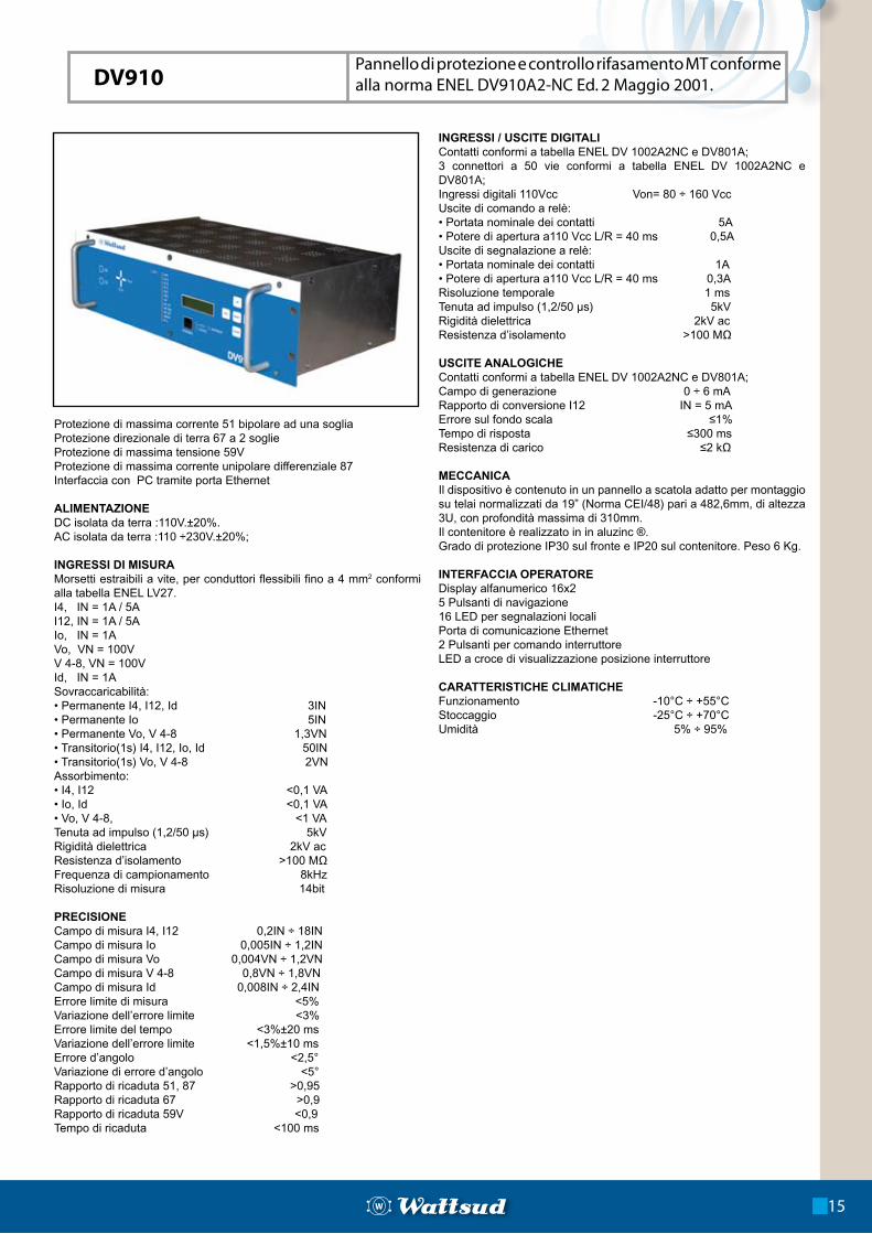
Pannello di protezione e controllo rifasamento MT conforme alla norma ENEL DV910A2-NC Ed. 2 Maggio 2001.
15
DV910
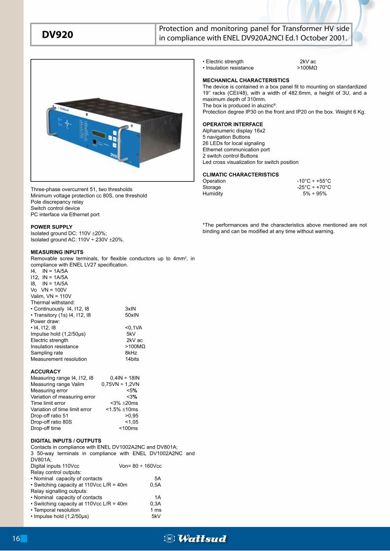
Three-phase overcurrent 51, two thresholdsMinimum voltage protection cc 80S, one thresholdPole discrepancy relaySwitch control devicePC interface via Ethernet port
POWER SUPPLYIsolated ground DC: 110V ±20%;Isolated ground AC: 110V ÷ 230V ±20%.
MEASURING INPUTSRemovable screw terminals, for flexible conductors up to 4mm2, in compliance with ENEL LV27 specification.I4, IN = 1A/5AI12, IN = 1A/5AI8, IN = 1A/5AVo VN = 100VValim, VN = 110VThermal withstand:• Continuously I4, I12, I8 3xIN• Transitory (1s) I4, I12, I8 50xINPower draw:• I4, I12, I8 <0,1VAImpulse hold (1,2/50µs) 5kVElectric strength 2kV acInsulation resistance >100MΩSampling rate 8kHzMeasurement resolution 14bits
ACCURACYMeasuring range I4, I12, I8 0,4IN ÷ 18INMeasuring range Valim 0,75VN ÷ 1,2VNMeasuring error <5% Variation of measuring error <3%Time limit error <3% ±20msVariation of time limit error <1.5% ±10msDrop-off ratio 51 >0,95Drop-off ratio 80S <1,05Drop-off time <100ms
DIGITAL INPUTS / OUTPUTSContacts in compliance with ENEL DV1002A2NC and DV801A;3 50-way terminals in compliance with ENEL DV1002A2NC and DV801A;Digital inputs 110Vcc Von= 80 ÷ 160VccRelay control outputs:• Nominal capacity of contacts 5A• Switching capacity at 110Vcc L/R = 40m 0,5ARelay signalling outputs:• Nominal capacity of contacts 1A• Switching capacity at 110Vcc L/R = 40m 0,3A• Temporal resolution 1 ms• Impulse hold (1,2/50µs) 5kV
• Electric strength 2kV ac• Insulation resistance >100MΩ
MECHANICAL CHARACTERISTICS The device is contained in a box panel fit to mounting on standardized 19’’ racks (CEI/48), with a width of 482.6mm, a height of 3U, and a maximum depth of 310mm. The box is produced in aluzinc®. Protection degree IP30 on the front and IP20 on the box. Weight 6 Kg.
OPERATOR INTERFACEAlphanumeric display 16x25 navigation Buttons26 LEDs for local signalingEthernet communication port2 switch control ButtonsLed cross visualization for switch position
CLIMATIC CHARACTERISTICSOperation -10°C ÷ +55°CStorage -25°C ÷ +70°CHumidity 5% ÷ 95%
*The performances and the characteristics above mentioned are not binding and can be modified at any time without warning.
16
DV920Protection and monitoring panel for Transformer HV side in compliance with ENEL DV920A2NCI Ed.1 October 2001.
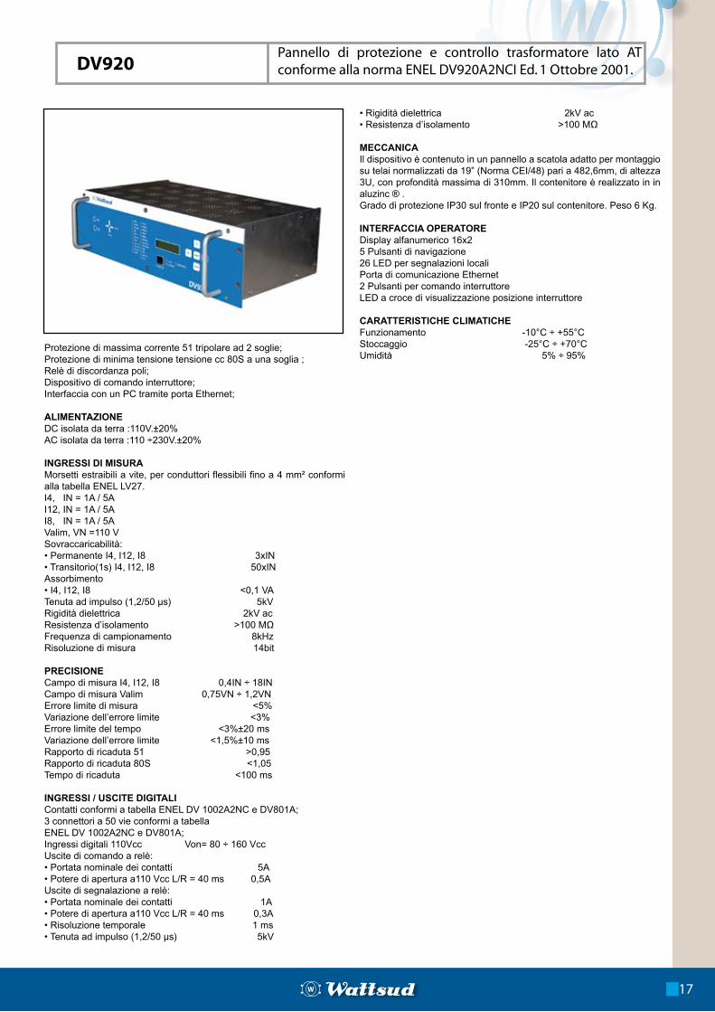
Protezione di massima corrente 51 tripolare ad 2 soglie;Protezione di minima tensione tensione cc 80S a una soglia ;Relè di discordanza poli;Dispositivo di comando interruttore;Interfaccia con un PC tramite porta Ethernet;
ALIMENTAZIONEDC isolata da terra :110V.±20%AC isolata da terra :110 ÷230V.±20%
INGRESSI DI MISURAMorsetti estraibili a vite, per conduttori flessibili fino a 4 mm² conformi alla tabella ENEL LV27.I4, IN = 1A / 5A I12, IN = 1A / 5A I8, IN = 1A / 5A Valim, VN =110 V Sovraccaricabilità:• Permanente I4, I12, I8 3xIN• Transitorio(1s) I4, I12, I8 50xINAssorbimento • I4, I12, I8 <0,1 VATenuta ad impulso (1,2/50 µs) 5kVRigidità dielettrica 2kV acResistenza d’isolamento >100 MΩFrequenza di campionamento 8kHzRisoluzione di misura 14bit
PRECISIONECampo di misura I4, I12, I8 0,4IN ÷ 18INCampo di misura Valim 0,75VN ÷ 1,2VNErrore limite di misura <5%Variazione dell’errore limite <3%Errore limite del tempo <3%±20 msVariazione dell’errore limite <1,5%±10 msRapporto di ricaduta 51 >0,95Rapporto di ricaduta 80S <1,05Tempo di ricaduta <100 ms
INGRESSI / USCITE DIGITALIContatti conformi a tabella ENEL DV 1002A2NC e DV801A;3 connettori a 50 vie conformi a tabella ENEL DV 1002A2NC e DV801A;Ingressi digitali 110Vcc Von= 80 ÷ 160 VccUscite di comando a relè:• Portata nominale dei contatti 5A• Potere di apertura a110 Vcc L/R = 40 ms 0,5AUscite di segnalazione a relè:• Portata nominale dei contatti 1A• Potere di apertura a110 Vcc L/R = 40 ms 0,3A• Risoluzione temporale 1 ms• Tenuta ad impulso (1,2/50 µs) 5kV
• Rigidità dielettrica 2kV ac• Resistenza d’isolamento >100 MΩ
MECCANICAIl dispositivo è contenuto in un pannello a scatola adatto per montaggio su telai normalizzati da 19” (Norma CEI/48) pari a 482,6mm, di altezza 3U, con profondità massima di 310mm. Il contenitore è realizzato in in aluzinc ® .Grado di protezione IP30 sul fronte e IP20 sul contenitore. Peso 6 Kg.
INTERFACCIA OPERATOREDisplay alfanumerico 16x25 Pulsanti di navigazione26 LED per segnalazioni localiPorta di comunicazione Ethernet2 Pulsanti per comando interruttoreLED a croce di visualizzazione posizione interruttore
CARATTERISTICHE CLIMATICHEFunzionamento -10°C ÷ +55°CStoccaggio -25°C ÷ +70°CUmidità 5% ÷ 95%
Pannello di protezione e controllo trasformatore lato AT conforme alla norma ENEL DV920A2NCI Ed. 1 Ottobre 2001.
17
DV920
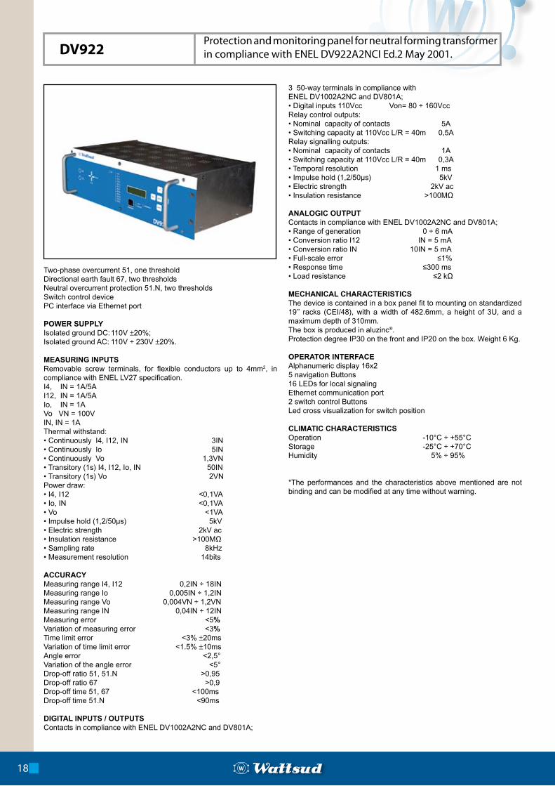
Two-phase overcurrent 51, one thresholdDirectional earth fault 67, two thresholdsNeutral overcurrent protection 51.N, two thresholdsSwitch control devicePC interface via Ethernet port
POWER SUPPLYIsolated ground DC: 110V ±20%;Isolated ground AC: 110V ÷ 230V ±20%.
MEASURING INPUTSRemovable screw terminals, for flexible conductors up to 4mm2, in compliance with ENEL LV27 specification.I4, IN = 1A/5AI12, IN = 1A/5AIo, IN = 1AVo VN = 100VIN, IN = 1AThermal withstand:• Continuously I4, I12, IN 3IN• Continuously Io 5IN• Continuously Vo 1,3VN• Transitory (1s) I4, I12, Io, IN 50IN• Transitory (1s) Vo 2VNPower draw:• I4, I12 <0,1VA• Io, IN <0,1VA• Vo <1VA• Impulse hold (1,2/50µs) 5kV• Electric strength 2kV ac• Insulation resistance >100MΩ• Sampling rate 8kHz• Measurement resolution 14bits
ACCURACYMeasuring range I4, I12 0,2IN ÷ 18INMeasuring range Io 0,005IN ÷ 1,2INMeasuring range Vo 0,004VN ÷ 1,2VNMeasuring range IN 0,04IN ÷ 12INMeasuring error <5%Variation of measuring error <3%Time limit error <3% ±20msVariation of time limit error <1.5% ±10msAngle error <2,5°Variation of the angle error <5°Drop-off ratio 51, 51.N >0,95Drop-off ratio 67 >0,9Drop-off time 51, 67 <100msDrop-off time 51.N <90ms
DIGITAL INPUTS / OUTPUTSContacts in compliance with ENEL DV1002A2NC and DV801A;
3 50-way terminals in compliance with ENEL DV1002A2NC and DV801A;• Digital inputs 110Vcc Von= 80 ÷ 160VccRelay control outputs:• Nominal capacity of contacts 5A• Switching capacity at 110Vcc L/R = 40m 0,5ARelay signalling outputs:• Nominal capacity of contacts 1A• Switching capacity at 110Vcc L/R = 40m 0,3A• Temporal resolution 1 ms• Impulse hold (1,2/50µs) 5kV• Electric strength 2kV ac• Insulation resistance >100MΩ
ANALOGIC OUTPUTContacts in compliance with ENEL DV1002A2NC and DV801A; • Range of generation 0 ÷ 6 mA• Conversion ratio I12 IN = 5 mA• Conversion ratio IN 10IN = 5 mA• Full-scale error ≤1%• Response time ≤300 ms• Load resistance ≤2 kΩ
MECHANICAL CHARACTERISTICS The device is contained in a box panel fit to mounting on standardized 19’’ racks (CEI/48), with a width of 482.6mm, a height of 3U, and a maximum depth of 310mm. The box is produced in aluzinc®. Protection degree IP30 on the front and IP20 on the box. Weight 6 Kg.
OPERATOR INTERFACEAlphanumeric display 16x25 navigation Buttons16 LEDs for local signalingEthernet communication port2 switch control ButtonsLed cross visualization for switch position
CLIMATIC CHARACTERISTICSOperation -10°C ÷ +55°CStorage -25°C ÷ +70°CHumidity 5% ÷ 95%
*The performances and the characteristics above mentioned are not binding and can be modified at any time without warning.
18
DV922Protection and monitoring panel for neutral forming transformer in compliance with ENEL DV922A2NCI Ed.2 May 2001.
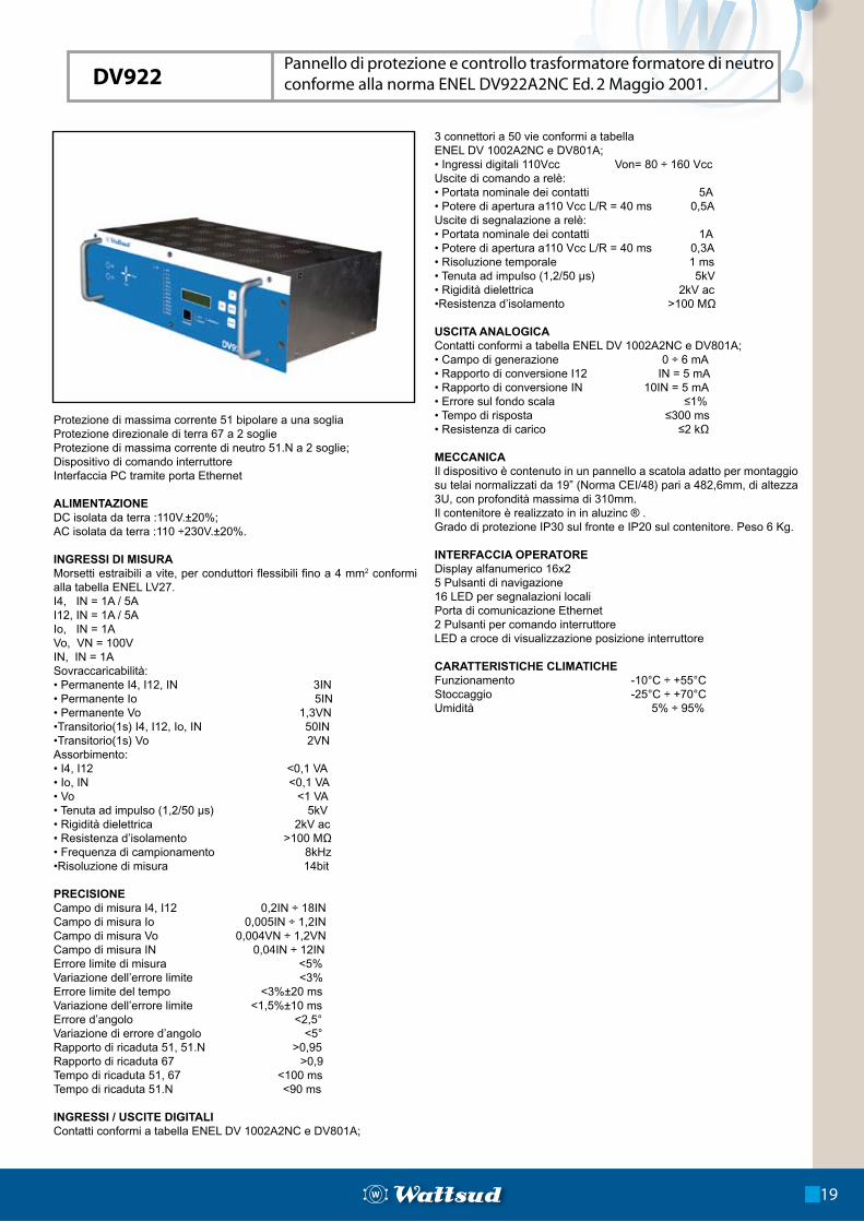
Protezione di massima corrente 51 bipolare a una sogliaProtezione direzionale di terra 67 a 2 soglieProtezione di massima corrente di neutro 51.N a 2 soglie;Dispositivo di comando interruttoreInterfaccia PC tramite porta Ethernet
ALIMENTAZIONEDC isolata da terra :110V.±20%;AC isolata da terra :110 ÷230V.±20%.
INGRESSI DI MISURAMorsetti estraibili a vite, per conduttori flessibili fino a 4 mm2 conformi alla tabella ENEL LV27.I4, IN = 1A / 5A I12, IN = 1A / 5A Io, IN = 1A Vo, VN = 100V IN, IN = 1A Sovraccaricabilità:• Permanente I4, I12, IN 3IN• Permanente Io 5IN• Permanente Vo 1,3VN•Transitorio(1s) I4, I12, Io, IN 50IN•Transitorio(1s) Vo 2VNAssorbimento:• I4, I12 <0,1 VA• Io, IN <0,1 VA• Vo <1 VA• Tenuta ad impulso (1,2/50 µs) 5kV• Rigidità dielettrica 2kV ac• Resistenza d’isolamento >100 MΩ• Frequenza di campionamento 8kHz•Risoluzione di misura 14bit
PRECISIONE Campo di misura I4, I12 0,2IN ÷ 18INCampo di misura Io 0,005IN ÷ 1,2INCampo di misura Vo 0,004VN ÷ 1,2VNCampo di misura IN 0,04IN ÷ 12INErrore limite di misura <5%Variazione dell’errore limite <3%Errore limite del tempo <3%±20 msVariazione dell’errore limite <1,5%±10 msErrore d’angolo <2,5°Variazione di errore d’angolo <5°Rapporto di ricaduta 51, 51.N >0,95Rapporto di ricaduta 67 >0,9Tempo di ricaduta 51, 67 <100 msTempo di ricaduta 51.N <90 ms
INGRESSI / USCITE DIGITALIContatti conformi a tabella ENEL DV 1002A2NC e DV801A;
3 connettori a 50 vie conformi a tabellaENEL DV 1002A2NC e DV801A;• Ingressi digitali 110Vcc Von= 80 ÷ 160 VccUscite di comando a relè:• Portata nominale dei contatti 5A• Potere di apertura a110 Vcc L/R = 40 ms 0,5AUscite di segnalazione a relè:• Portata nominale dei contatti 1A• Potere di apertura a110 Vcc L/R = 40 ms 0,3A• Risoluzione temporale 1 ms• Tenuta ad impulso (1,2/50 µs) 5kV• Rigidità dielettrica 2kV ac•Resistenza d’isolamento >100 MΩ
USCITA ANALOGICAContatti conformi a tabella ENEL DV 1002A2NC e DV801A;• Campo di generazione 0 ÷ 6 mA• Rapporto di conversione I12 IN = 5 mA• Rapporto di conversione IN 10IN = 5 mA• Errore sul fondo scala ≤1%• Tempo di risposta ≤300 ms• Resistenza di carico ≤2 kΩ
MECCANICAIl dispositivo è contenuto in un pannello a scatola adatto per montaggio su telai normalizzati da 19” (Norma CEI/48) pari a 482,6mm, di altezza 3U, con profondità massima di 310mm.Il contenitore è realizzato in in aluzinc ® .Grado di protezione IP30 sul fronte e IP20 sul contenitore. Peso 6 Kg.
INTERFACCIA OPERATOREDisplay alfanumerico 16x25 Pulsanti di navigazione16 LED per segnalazioni localiPorta di comunicazione Ethernet2 Pulsanti per comando interruttoreLED a croce di visualizzazione posizione interruttore
CARATTERISTICHE CLIMATICHEFunzionamento -10°C ÷ +55°CStoccaggio -25°C ÷ +70°CUmidità 5% ÷ 95%
Pannello di protezione e controllo trasformatore formatore di neutro conforme alla norma ENEL DV922A2NC Ed. 2 Maggio 2001.
19
DV922
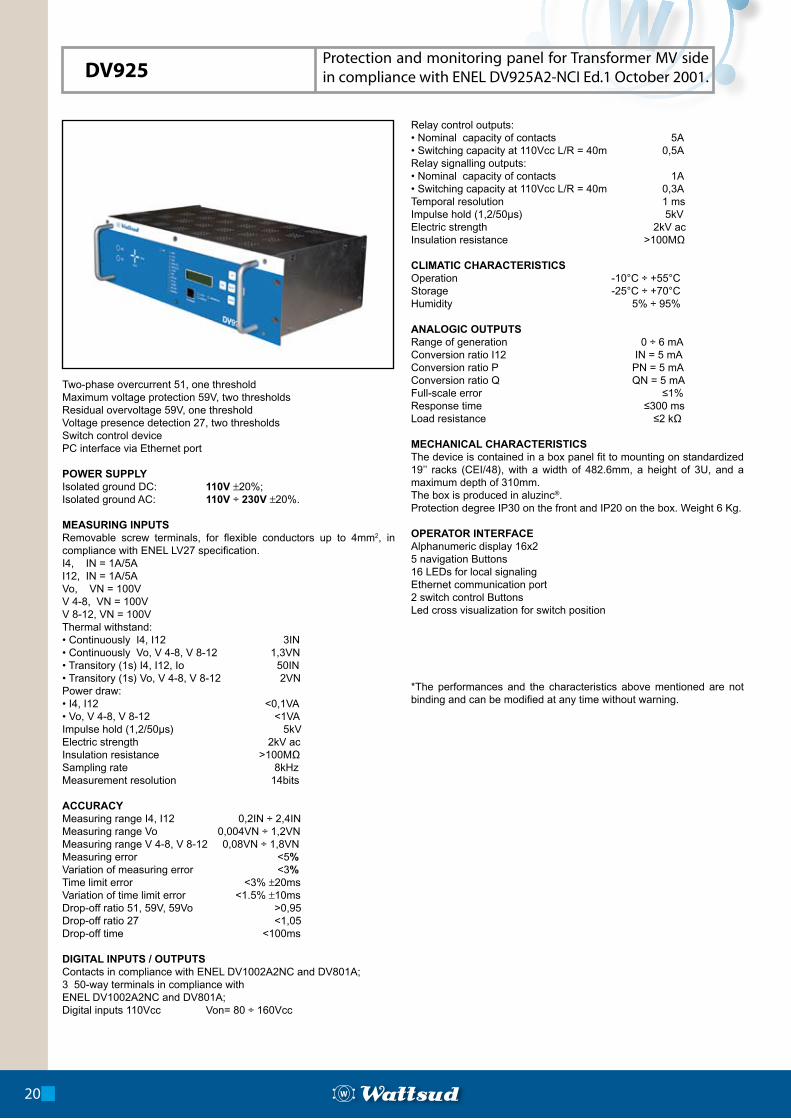
Two-phase overcurrent 51, one thresholdMaximum voltage protection 59V, two thresholdsResidual overvoltage 59V, one thresholdVoltage presence detection 27, two thresholds Switch control devicePC interface via Ethernet port
POWER SUPPLYIsolated ground DC: 110V ±20%;Isolated ground AC: 110V ÷ 230V ±20%.
MEASURING INPUTSRemovable screw terminals, for flexible conductors up to 4mm2, in compliance with ENEL LV27 specification.I4, IN = 1A/5AI12, IN = 1A/5AVo, VN = 100VV 4-8, VN = 100VV 8-12, VN = 100VThermal withstand:• Continuously I4, I12 3IN• Continuously Vo, V 4-8, V 8-12 1,3VN• Transitory (1s) I4, I12, Io 50IN• Transitory (1s) Vo, V 4-8, V 8-12 2VNPower draw:• I4, I12 <0,1VA • Vo, V 4-8, V 8-12 <1VAImpulse hold (1,2/50µs) 5kVElectric strength 2kV acInsulation resistance >100MΩSampling rate 8kHzMeasurement resolution 14bits
ACCURACYMeasuring range I4, I12 0,2IN ÷ 2,4INMeasuring range Vo 0,004VN ÷ 1,2VNMeasuring range V 4-8, V 8-12 0,08VN ÷ 1,8VNMeasuring error <5%Variation of measuring error <3%Time limit error <3% ±20msVariation of time limit error <1.5% ±10msDrop-off ratio 51, 59V, 59Vo >0,95Drop-off ratio 27 <1,05Drop-off time <100ms
DIGITAL INPUTS / OUTPUTSContacts in compliance with ENEL DV1002A2NC and DV801A;3 50-way terminals in compliance with ENEL DV1002A2NC and DV801A;Digital inputs 110Vcc Von= 80 ÷ 160Vcc
Relay control outputs:• Nominal capacity of contacts 5A• Switching capacity at 110Vcc L/R = 40m 0,5ARelay signalling outputs:• Nominal capacity of contacts 1A• Switching capacity at 110Vcc L/R = 40m 0,3ATemporal resolution 1 msImpulse hold (1,2/50µs) 5kVElectric strength 2kV acInsulation resistance >100MΩ
CLIMATIC CHARACTERISTICSOperation -10°C ÷ +55°CStorage -25°C ÷ +70°CHumidity 5% ÷ 95%
ANALOGIC OUTPUTSRange of generation 0 ÷ 6 mAConversion ratio I12 IN = 5 mAConversion ratio P PN = 5 mAConversion ratio Q QN = 5 mAFull-scale error ≤1%Response time ≤300 msLoad resistance ≤2 kΩ
MECHANICAL CHARACTERISTICS The device is contained in a box panel fit to mounting on standardized 19’’ racks (CEI/48), with a width of 482.6mm, a height of 3U, and a maximum depth of 310mm. The box is produced in aluzinc®. Protection degree IP30 on the front and IP20 on the box. Weight 6 Kg.
OPERATOR INTERFACEAlphanumeric display 16x25 navigation Buttons16 LEDs for local signalingEthernet communication port2 switch control ButtonsLed cross visualization for switch position
*The performances and the characteristics above mentioned are not binding and can be modified at any time without warning.
20
DV925Protection and monitoring panel for Transformer MV side in compliance with ENEL DV925A2-NCI Ed.1 October 2001.
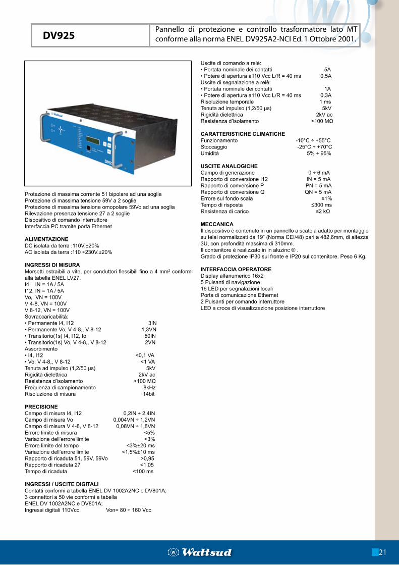
Protezione di massima corrente 51 bipolare ad una sogliaProtezione di massima tensione 59V a 2 soglieProtezione di massima tensione omopolare 59Vo ad una sogliaRilevazione presenza tensione 27 a 2 soglieDispositivo di comando interruttoreInterfaccia PC tramite porta Ethernet
ALIMENTAZIONEDC isolata da terra :110V.±20%AC isolata da terra :110 ÷230V.±20%
INGRESSI DI MISURAMorsetti estraibili a vite, per conduttori flessibili fino a 4 mm2 conformi alla tabella ENEL LV27.I4, IN = 1A / 5A I12, IN = 1A / 5A Vo, VN = 100V V 4-8, VN = 100V V 8-12, VN = 100V Sovraccaricabilità:• Permanente I4, I12 3IN• Permanente Vo, V 4-8,, V 8-12 1,3VN• Transitorio(1s) I4, I12, Io 50IN• Transitorio(1s) Vo, V 4-8,, V 8-12 2VNAssorbimento • I4, I12 <0,1 VA• Vo, V 4-8,, V 8-12 <1 VATenuta ad impulso (1,2/50 µs) 5kVRigidità dielettrica 2kV acResistenza d’isolamento >100 MΩFrequenza di campionamento 8kHzRisoluzione di misura 14bit
PRECISIONECampo di misura I4, I12 0,2IN ÷ 2,4INCampo di misura Vo 0,004VN ÷ 1,2VNCampo di misura V 4-8, V 8-12 0,08VN ÷ 1,8VNErrore limite di misura <5%Variazione dell’errore limite <3%Errore limite del tempo <3%±20 msVariazione dell’errore limite <1,5%±10 msRapporto di ricaduta 51, 59V, 59Vo >0,95Rapporto di ricaduta 27 <1,05Tempo di ricaduta <100 ms
INGRESSI / USCITE DIGITALIContatti conformi a tabella ENEL DV 1002A2NC e DV801A;3 connettori a 50 vie conformi a tabellaENEL DV 1002A2NC e DV801A;Ingressi digitali 110Vcc Von= 80 ÷ 160 Vcc
Uscite di comando a relè:• Portata nominale dei contatti 5A• Potere di apertura a110 Vcc L/R = 40 ms 0,5AUscite di segnalazione a relè:• Portata nominale dei contatti 1A• Potere di apertura a110 Vcc L/R = 40 ms 0,3ARisoluzione temporale 1 msTenuta ad impulso (1,2/50 µs) 5kVRigidità dielettrica 2kV acResistenza d’isolamento >100 MΩ
CARATTERISTICHE CLIMATICHEFunzionamento -10°C ÷ +55°CStoccaggio -25°C ÷ +70°CUmidità 5% ÷ 95%
USCITE ANALOGICHECampo di generazione 0 ÷ 6 mARapporto di conversione I12 IN = 5 mARapporto di conversione P PN = 5 mARapporto di conversione Q QN = 5 mAErrore sul fondo scala ≤1%Tempo di risposta ≤300 msResistenza di carico ≤2 kΩ
MECCANICAIl dispositivo è contenuto in un pannello a scatola adatto per montaggio su telai normalizzati da 19” (Norma CEI/48) pari a 482,6mm, di altezza 3U, con profondità massima di 310mm.Il contenitore è realizzato in in aluzinc ® .Grado di protezione IP30 sul fronte e IP20 sul contenitore. Peso 6 Kg.
INTERFACCIA OPERATOREDisplay alfanumerico 16x25 Pulsanti di navigazione16 LED per segnalazioni localiPorta di comunicazione Ethernet2 Pulsanti per comando interruttoreLED a croce di visualizzazione posizione interruttore
Pannello di protezione e controllo trasformatore lato MT conforme alla norma ENEL DV925A2-NCI Ed. 1 Ottobre 2001.
21
DV925
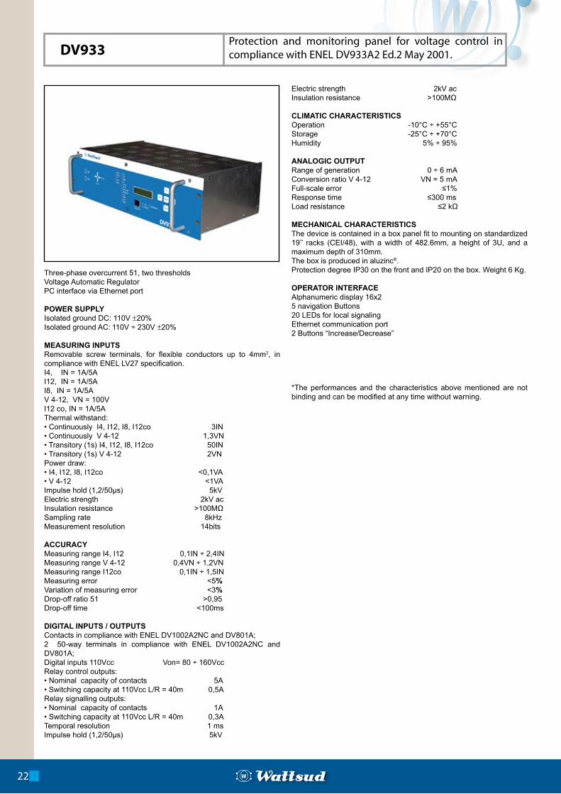
Three-phase overcurrent 51, two thresholdsVoltage Automatic Regulator PC interface via Ethernet port
POWER SUPPLYIsolated ground DC: 110V ±20%Isolated ground AC: 110V ÷ 230V ±20%
MEASURING INPUTSRemovable screw terminals, for flexible conductors up to 4mm2, in compliance with ENEL LV27 specification.I4, IN = 1A/5AI12, IN = 1A/5AI8, IN = 1A/5AV 4-12, VN = 100VI12 co, IN = 1A/5A Thermal withstand:• Continuously I4, I12, I8, I12co 3IN• Continuously V 4-12 1,3VN• Transitory (1s) I4, I12, I8, I12co 50IN• Transitory (1s) V 4-12 2VNPower draw:• I4, I12, I8, I12co <0,1VA• V 4-12 <1VAImpulse hold (1,2/50µs) 5kVElectric strength 2kV acInsulation resistance >100MΩSampling rate 8kHzMeasurement resolution 14bits
ACCURACYMeasuring range I4, I12 0,1IN ÷ 2,4INMeasuring range V 4-12 0,4VN ÷ 1,2VNMeasuring range I12co 0,1IN ÷ 1,5INMeasuring error <5%Variation of measuring error <3%Drop-off ratio 51 >0,95Drop-off time <100ms
DIGITAL INPUTS / OUTPUTSContacts in compliance with ENEL DV1002A2NC and DV801A;2 50-way terminals in compliance with ENEL DV1002A2NC and DV801A;Digital inputs 110Vcc Von= 80 ÷ 160VccRelay control outputs:• Nominal capacity of contacts 5A• Switching capacity at 110Vcc L/R = 40m 0,5ARelay signalling outputs:• Nominal capacity of contacts 1A• Switching capacity at 110Vcc L/R = 40m 0,3ATemporal resolution 1 msImpulse hold (1,2/50µs) 5kV
Electric strength 2kV acInsulation resistance >100MΩ
CLIMATIC CHARACTERISTICSOperation -10°C ÷ +55°CStorage -25°C ÷ +70°CHumidity 5% ÷ 95%
ANALOGIC OUTPUTRange of generation 0 ÷ 6 mAConversion ratio V 4-12 VN = 5 mAFull-scale error ≤1%Response time ≤300 msLoad resistance ≤2 kΩ
MECHANICAL CHARACTERISTICS The device is contained in a box panel fit to mounting on standardized 19’’ racks (CEI/48), with a width of 482.6mm, a height of 3U, and a maximum depth of 310mm. The box is produced in aluzinc®. Protection degree IP30 on the front and IP20 on the box. Weight 6 Kg.
OPERATOR INTERFACEAlphanumeric display 16x25 navigation Buttons20 LEDs for local signalingEthernet communication port2 Buttons “Increase/Decrease”
*The performances and the characteristics above mentioned are not binding and can be modified at any time without warning.
22
DV933Protection and monitoring panel for voltage control in compliance with ENEL DV933A2 Ed.2 May 2001.
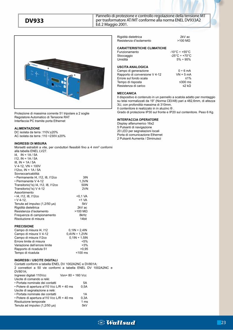
Protezione di massima corrente 51 tripolare a 2 soglieRegolatore Automatico di Tensione RATInterfaccia PC tramite porta Ethernet
ALIMENTAZIONEDC isolata da terra :110V.±20%AC isolata da terra :110 ÷230V.±20%
INGRESSI DI MISURAMorsetti estraibili a vite, per conduttori flessibili fino a 4 mm² conformi alla tabella ENEL LV27.I4, IN = 1A / 5A I12, IN = 1A / 5A I8, IN = 1A / 5A V 4-12, VN = 100V I12co, IN = 1A / 5A Sovraccaricabilità:• Permanente I4, I12, I8, I12co 3IN• Permanente V 4-12 1,3VNTransitorio(1s) I4, I12, I8, I12co 50INTransitorio(1s) V 4-12 2VNAssorbimento • I4, I12, I8, I12co <0,1 VA• V 4-12, <1 VATenuta ad impulso (1,2/50 µs) 5kVRigidità dielettrica 2kV acResistenza d’isolamento >100 MΩFrequenza di campionamento 8kHzRisoluzione di misura 14bit
PRECISIONECampo di misura I4, I12 0,1IN ÷ 2,4INCampo di misura V 4-12 0,4VN ÷ 1,2VNCampo di misura I12co 0,1IN ÷ 1,5INErrore limite di misura <5%Variazione dell’errore limite <3%Rapporto di ricaduta 51 >0,95Tempo di ricaduta <100 ms
INGRESSI / USCITE DIGITALIContatti conformi a tabella ENEL DV 1002A2NC e DV801A;2 connettori a 50 vie conformi a tabella ENEL DV 1002A2NC e DV801A;Ingressi digitali 110Vcc Von= 80 ÷ 160 VccUscite di comando a relè:• Portata nominale dei contatti 5A• Potere di apertura a110 Vcc L/R = 40 ms 0,5AUscite di segnalazione a relè:• Portata nominale dei contatti 1A• Potere di apertura a110 Vcc L/R = 40 ms 0,3ARisoluzione temporale 1 msTenuta ad impulso (1,2/50 µs) 5kV
Rigidità dielettrica 2kV acResistenza d’isolamento >100 MΩ
CARATTERISTICHE CLIMATICHEFunzionamento -10°C ÷ +55°CStoccaggio -25°C ÷ +70°CUmidità 5% ÷ 95%
USCITA ANALOGICACampo di generazione 0 ÷ 6 mARapporto di conversione V 4-12 VN = 5 mAErrore sul fondo scala ≤1%Tempo di risposta ≤300 msResistenza di carico ≤2 kΩ
MECCANICAIl dispositivo è contenuto in un pannello a scatola adatto per montaggio su telai normalizzati da 19” (Norma CEI/48) pari a 482,6mm, di altezza 3U, con profondità massima di 310mm.Il contenitore è realizzato in in aluzinc ® .Grado di protezione IP30 sul fronte e IP20 sul contenitore. Peso 6 Kg.
INTERFACCIA OPERATOREDisplay alfanumerico 16x25 Pulsanti di navigazione20 LED per segnalazioni localiPorta di comunicazione Ethernet2 Pulsanti Aumenta / Diminuisci
Pannello di protezione e controllo regolazione della tensione MT per trasformatore AT/MT conforme alla norma ENEL DV933A2 Ed. 2 Maggio 2001.
23
DV933
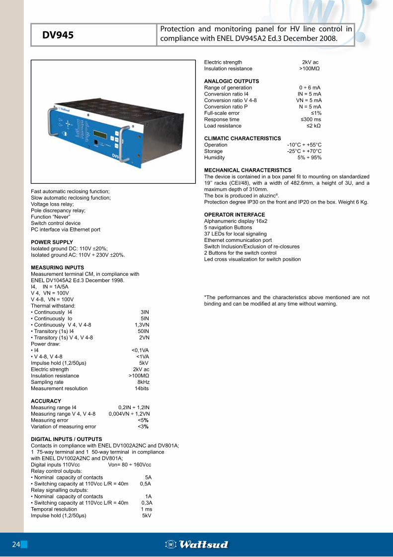
Fast automatic reclosing function;Slow automatic reclosing function; Voltage loss relay;Pole discrepancy relay;Function “Never”Switch control devicePC interface via Ethernet port
POWER SUPPLYIsolated ground DC: 110V ±20%;Isolated ground AC: 110V ÷ 230V ±20%.
MEASURING INPUTSMeasurement terminal CM, in compliance withENEL DV1045A2 Ed.3 December 1998.I4, IN = 1A/5AV 4, VN = 100VV 4-8, VN = 100VThermal withstand:• Continuously I4 3IN• Continuously Io 5IN• Continuously V 4, V 4-8 1,3VN• Transitory (1s) I4 50IN• Transitory (1s) V 4, V 4-8 2VNPower draw: • I4 <0,1VA• V 4-8, V 4-8 <1VAImpulse hold (1,2/50µs) 5kVElectric strength 2kV acInsulation resistance >100MΩSampling rate 8kHzMeasurement resolution 14bits
ACCURACYMeasuring range I4 0,2IN ÷ 1,2INMeasuring range V 4, V 4-8 0,004VN ÷ 1,2VNMeasuring error <5% Variation of measuring error <3%
DIGITAL INPUTS / OUTPUTSContacts in compliance with ENEL DV1002A2NC and DV801A;1 75-way terminal and 1 50-way terminal in compliancewith ENEL DV1002A2NC and DV801A;Digital inputs 110Vcc Von= 80 ÷ 160VccRelay control outputs:• Nominal capacity of contacts 5A• Switching capacity at 110Vcc L/R = 40m 0,5ARelay signalling outputs:• Nominal capacity of contacts 1A• Switching capacity at 110Vcc L/R = 40m 0,3ATemporal resolution 1 msImpulse hold (1,2/50µs) 5kV
Electric strength 2kV acInsulation resistance >100MΩ
ANALOGIC OUTPUTS Range of generation 0 ÷ 6 mAConversion ratio I4 IN = 5 mAConversion ratio V 4-8 VN = 5 mAConversion ratio P N = 5 mAFull-scale error ≤1%Response time ≤300 msLoad resistance ≤2 kΩ
CLIMATIC CHARACTERISTICSOperation -10°C ÷ +55°CStorage -25°C ÷ +70°CHumidity 5% ÷ 95%
MECHANICAL CHARACTERISTICS The device is contained in a box panel fit to mounting on standardized 19’’ racks (CEI/48), with a width of 482.6mm, a height of 3U, and a maximum depth of 310mm. The box is produced in aluzinc®. Protection degree IP30 on the front and IP20 on the box. Weight 6 Kg.
OPERATOR INTERFACEAlphanumeric display 16x25 navigation Buttons37 LEDs for local signalingEthernet communication portSwitch Inclusion/Exclusion of re-closures 2 Buttons for the switch controlLed cross visualization for switch position
*The performances and the characteristics above mentioned are not binding and can be modified at any time without warning.
24
DV945Protection and monitoring panel for HV line control in compliance with ENEL DV945A2 Ed.3 December 2008.
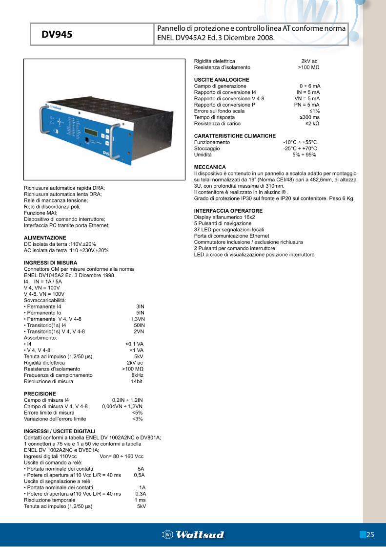
Richiusura automatica rapida DRA;Richiusura automatica lenta DRA;Relè di mancanza tensione;Relè di discordanza poli;Funzione MAI;Dispositivo di comando interruttore;Interfaccia PC tramite porta Ethernet;
ALIMENTAZIONEDC isolata da terra :110V.±20%AC isolata da terra :110 ÷230V.±20%
INGRESSI DI MISURAConnettore CM per misure conforme alla normaENEL DV1045A2 Ed. 3 Dicembre 1998.I4, IN = 1A / 5AV 4, VN = 100VV 4-8, VN = 100VSovraccaricabilità:• Permanente I4 3IN• Permanente Io 5IN• Permanente V 4, V 4-8 1,3VN• Transitorio(1s) I4 50IN• Transitorio(1s) V 4, V 4-8 2VNAssorbimento:• I4 <0,1 VA• V 4, V 4-8, <1 VATenuta ad impulso (1,2/50 µs) 5kVRigidità dielettrica 2kV acResistenza d’isolamento >100 MΩFrequenza di campionamento 8kHzRisoluzione di misura 14bit
PRECISIONECampo di misura I4 0,2IN ÷ 1,2INCampo di misura V 4, V 4-8 0,004VN ÷ 1,2VNErrore limite di misura <5%Variazione dell’errore limite <3%
INGRESSI / USCITE DIGITALIContatti conformi a tabella ENEL DV 1002A2NC e DV801A;1 connettori a 75 vie e 1 a 50 vie conformi a tabella ENEL DV 1002A2NC e DV801A;Ingressi digitali 110Vcc Von= 80 ÷ 160 VccUscite di comando a relè:• Portata nominale dei contatti 5A• Potere di apertura a110 Vcc L/R = 40 ms 0,5AUscite di segnalazione a relè:• Portata nominale dei contatti 1A• Potere di apertura a110 Vcc L/R = 40 ms 0,3ARisoluzione temporale 1 msTenuta ad impulso (1,2/50 µs) 5kV
Rigidità dielettrica 2kV acResistenza d’isolamento >100 MΩ
USCITE ANALOGICHECampo di generazione 0 ÷ 6 mARapporto di conversione I4 IN = 5 mARapporto di conversione V 4-8 VN = 5 mARapporto di conversione P PN = 5 mAErrore sul fondo scala ≤1%Tempo di risposta ≤300 msResistenza di carico ≤2 kΩ
CARATTERISTICHE CLIMATICHEFunzionamento -10°C ÷ +55°CStoccaggio -25°C ÷ +70°CUmidità 5% ÷ 95%
MECCANICAIl dispositivo è contenuto in un pannello a scatola adatto per montaggio su telai normalizzati da 19” (Norma CEI/48) pari a 482,6mm, di altezza 3U, con profondità massima di 310mm.Il contenitore è realizzato in in aluzinc ® .Grado di protezione IP30 sul fronte e IP20 sul contenitore. Peso 6 Kg.
INTERFACCIA OPERATOREDisplay alfanumerico 16x25 Pulsanti di navigazione37 LED per segnalazioni localiPorta di comunicazione EthernetCommutatore inclusione / esclusione richiusura2 Pulsanti per comando interruttoreLED a croce di visualizzazione posizione interruttore
Pannello di protezione e controllo linea AT conforme norma ENEL DV945A2 Ed. 3 Dicembre 2008.
25
DV945
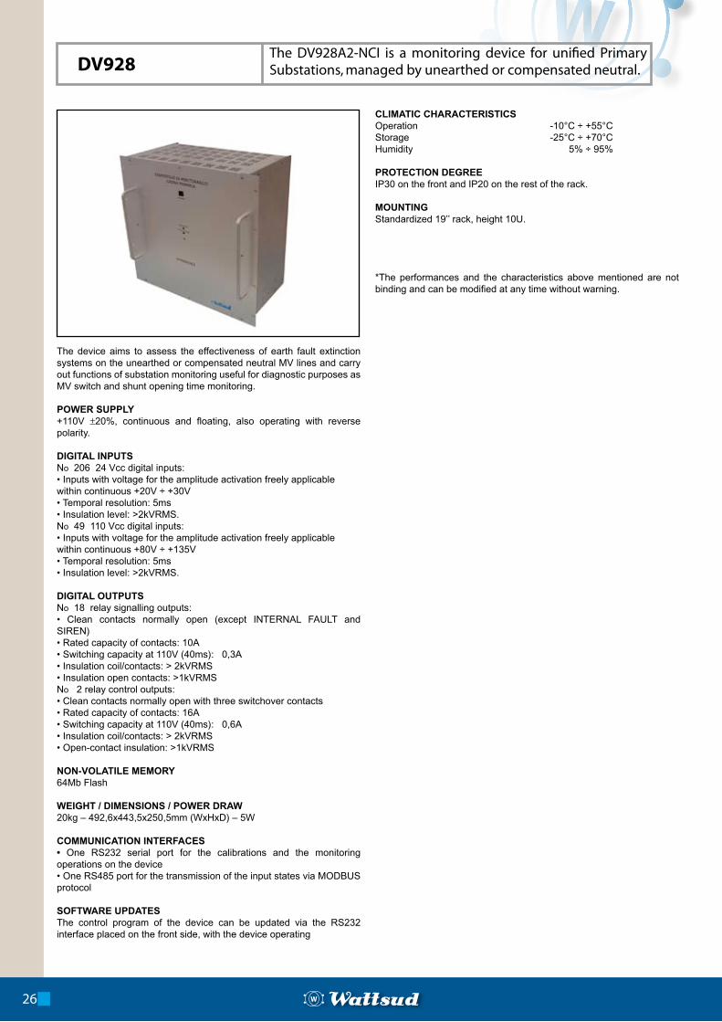
The device aims to assess the effectiveness of earth fault extinction systems on the unearthed or compensated neutral MV lines and carry out functions of substation monitoring useful for diagnostic purposes as MV switch and shunt opening time monitoring.
POWER SUPPLY+110V ±20%, continuous and floating, also operating with reverse polarity.
DIGITAL INPUTSNo 206 24 Vcc digital inputs:• Inputs with voltage for the amplitude activation freely applicablewithin continuous +20V ÷ +30V• Temporal resolution: 5ms• Insulation level: >2kVRMS.No 49 110 Vcc digital inputs:• Inputs with voltage for the amplitude activation freely applicablewithin continuous +80V ÷ +135V• Temporal resolution: 5ms• Insulation level: >2kVRMS.
DIGITAL OUTPUTSNo 18 relay signalling outputs: • Clean contacts normally open (except INTERNAL FAULT and SIREN)• Rated capacity of contacts: 10A• Switching capacity at 110V (40ms): 0,3A• Insulation coil/contacts: > 2kVRMS• Insulation open contacts: >1kVRMSNo 2 relay control outputs:• Clean contacts normally open with three switchover contacts• Rated capacity of contacts: 16A• Switching capacity at 110V (40ms): 0,6A• Insulation coil/contacts: > 2kVRMS• Open-contact insulation: >1kVRMS
NON-VOLATILE MEMORY64Mb Flash
WEIGHT / DIMENSIONS / POWER DRAW20kg – 492,6x443,5x250,5mm (WxHxD) – 5W
COMMUNICATION INTERFACES• One RS232 serial port for the calibrations and the monitoring operations on the device• One RS485 port for the transmission of the input states via MODBUS protocol
SOFTWARE UPDATESThe control program of the device can be updated via the RS232 interface placed on the front side, with the device operating
CLIMATIC CHARACTERISTICSOperation -10°C ÷ +55°CStorage -25°C ÷ +70°CHumidity 5% ÷ 95%
PROTECTION DEGREEIP30 on the front and IP20 on the rest of the rack.
MOUNTINGStandardized 19’’ rack, height 10U.
*The performances and the characteristics above mentioned are not binding and can be modified at any time without warning.
26
DV928The DV928A2-NCI is a monitoring device for unified Primary Substations, managed by unearthed or compensated neutral.
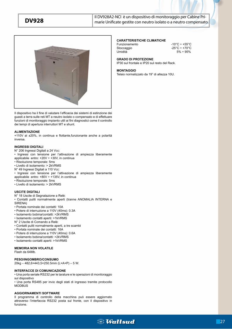
Il dispositivo ha il fine di valutare l’efficacia dei sistemi di estinzione dei guasti a terra sulle reti MT a neutro isolato o compensato e di effettuare funzioni di monitoraggio impianto utili ai fini diagnostici come il controllo dei tempi di apertura interruttori MT e shunt.
ALIMENTAZIONE+110V al ±20%, in continua e flottante,funzionante anche a polarità inversa.
INGRESSI DIGITALIN° 206 Ingressi Digitali a 24 Vcc:• Ingressi con tensione per l’attivazione di ampiezza liberamente applicabile entro: +20V ÷ +30V, in continua• Risoluzione temporale: 5ms• Livello di isolamento: > 2kVRMSN° 49 Ingressi Digitali a 110 Vcc:• Ingressi con tensione per l’attivazione di ampiezza liberamente applicabile entro: +80V ÷ +135V, in continua• Risoluzione temporale: 5ms• Livello di isolamento: > 2kVRMS
USCITE DIGITALIN° 18 Uscite di Segnalazione a Relè:• Contatti puliti normalmente aperti (tranne ANOMALIA INTERNA e SIRENA)• Portata nominale dei contatti: 10A• Potere di interruzione a 110V (40ms): 0.3A• Isolamento bobina/contatti: >2kVRMS• Isolamento contatti aperti: >1kVRMSN° 2 Uscite di Comando a Relè:• Contatti puliti normalmente aperti, a tre scambi• Portata nominale dei contatti: 16A• Potere di interruzione a 110V (40ms): 0.6A• Isolamento bobina/contatti: >2kVRMS• Isolamento contatti aperti: >1kVRMS
MEMORIA NON VOLATILEFlash da 64Mb.
PESO/INGOMBRO/CONSUMO20kg – 482,6×443,5×250.5mm (L×A×P) – 5 W.
INTERFACCE DI COMUNICAZIONE• Una porta seriale RS232 per le tarature e le operazioni di monitoraggio sul dispositivo• Una porta RS485 per invio degli stati di ingresso tramite protocollo MODBUS
AGGIORNAMENTI SOFTWAREIl programma di controllo della macchina può essere aggiornato attraverso l’interfaccia RS232 posta sul fronte, con il dispositivo in funzione.
CARATTERISTICHE CLIMATICHEFunzionamento -10°C ÷ +55°CStoccaggio -25°C ÷ +70°CUmidità 5% ÷ 95%
GRADO DI PROTEZIONEIP30 sul frontale e IP20 sul resto del Rack.
MONTAGGIOTelaio normalizzato da 19” di altezza 10U.
Il DV928A2-NCI è un dispositivo di monitoraggio per Cabine Pri-marie Unificate gestite con neutro isolato o a neutro compensato.
27
DV928
POWER SUPPLY110Vcc ±20%
MECHANICAL CHARACTERISTICS Standardized 19’’/9U rack.
CLIMATIC CHARACTERISTICSOperation -10°C ÷ +55°CStorage -25°C ÷ +70°CHumidity 5% ÷ 95%
ANALOGIC INPUTSNo 8 voltage channels• Rated capacity 400VRMS• Rated accuracy 0.2%• Useful interval 4VRMS ÷ 700VRMS• Max. error on the useful interval 1%• Full-scale 800VRMS• Differential resolution 16bits• Insulation 2kVRMS ÷ Impulse: 5kV- Bandwidth 3.25kHzNo 24 current channels• Rated capacities 1ARMS/5ARMS• Rated accuracy 0.2%• Useful interval 1ARMS 0.04ARMS ÷ 30ARMS• Useful interval 5ARMS 0.2ARMS ÷ 150ARMS• Max. error on the useful interval 2.5%• Full-scale on 1ARMS 36ARMS• Full-scale on 5ARMS 180ARMS• Differential resolution 16bits• Insulation 2kVRMS ÷ Impulse: 5kV• Bandwidth 3.25kHz
DIGITAL INPUTSNo 128 digital channels:• DC inputs, not polarized, with voltage freely applicable from a minimum of 18V to a maximum of 135V• Temporal resolution: 400 µs• Insulation: 2kVRMS ÷ Impulse: 5kV
SYNCHRONISMEvery record is connected with the reference of date and time, synchronized by the satellite reception system GPS, integrated or settable by the user through a synchronization with date and time of Windows®.
SAMPLING• Synchronous sampling rate for the 32 analogic and the 128 digital channels.• Analogic sampling rates:1. 12.5kHz “ 250 samples x 20ms
2. 10.0kHz “ 200 samples x 20m3. 5.0kHz “ 100 samples x 20ms4. 2.5kHz “ 50 samples x 20ms• Digital sampling rate: 2.5kHz “ 50 samples x 20ms
MEMORY CAPACITY512Mb which determine the following capacities:• 8 minutes – 12.5kHz• 10minutes – 10.0kHz• 18 minutes – 5.0kHz• 32 minutes – 2.5kHz• Up to 999 independent memories• Full-fill or Circular Memory
POWER DRAWNominal: 42VA – Maximum: 55VA
START OF THE RECORDSAnalogic channels:• Minimum RMS threshold;• Maximum RMS threshold;• Gradient threshold;• Independent trigger enabling on each channel and on each of the three available thresholds;• Trigger automatic disabling for threshold exceeding, till the reset of values within thresholds;Digital channels:• Falling edge;• Raising edge;• State changes;• Trigger enabling settable in independent way on each channel, using one of the three modes of intervention.Start-up combinations:With three selectors the combinations AND or OR can be set among the groups of signals enabled to the trigger, obtaining 8 possible logic combinations of start-up between the analogic and digital signals.Manual trigger:Thanks to the software provided, a manual record can be started, with no need of an active trigger on the inputs.
DURATION OF RECORDS• Pre-fault memory: 40ms ÷ 1s, by intervals of 40ms;• Fault memory: 80ms ÷ 60s, by intervals of 40ms;• Post- fault memory: 80ms ÷ 1s, by intervals of 40ms;
SPECIAL FUNCTIONSReal time monitoring of acquisitions:• ANALOGIC MONITOR;• DIGITAL MONITOR.RELAY TEST function to check the outputs, with software management of contacts.The Firmware can be updated in-circuit via the Ethernet port.
COMMUNICATION PORTS • Ethernet port 10/100Mbps with TCP/IP protocol and automatic download function, download interruption and resumption. • Two RS232C ports from 9.6kbps to 57.6kbps, with automatic download function, download interruption and resumption.
WEIGHT AND DIMENSIONS16.8kg – 482x4000x246mm (WxHxD)
*The performances and the characteristics above mentioned are not binding and can be modified at any time without warning.
28
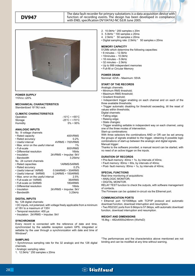
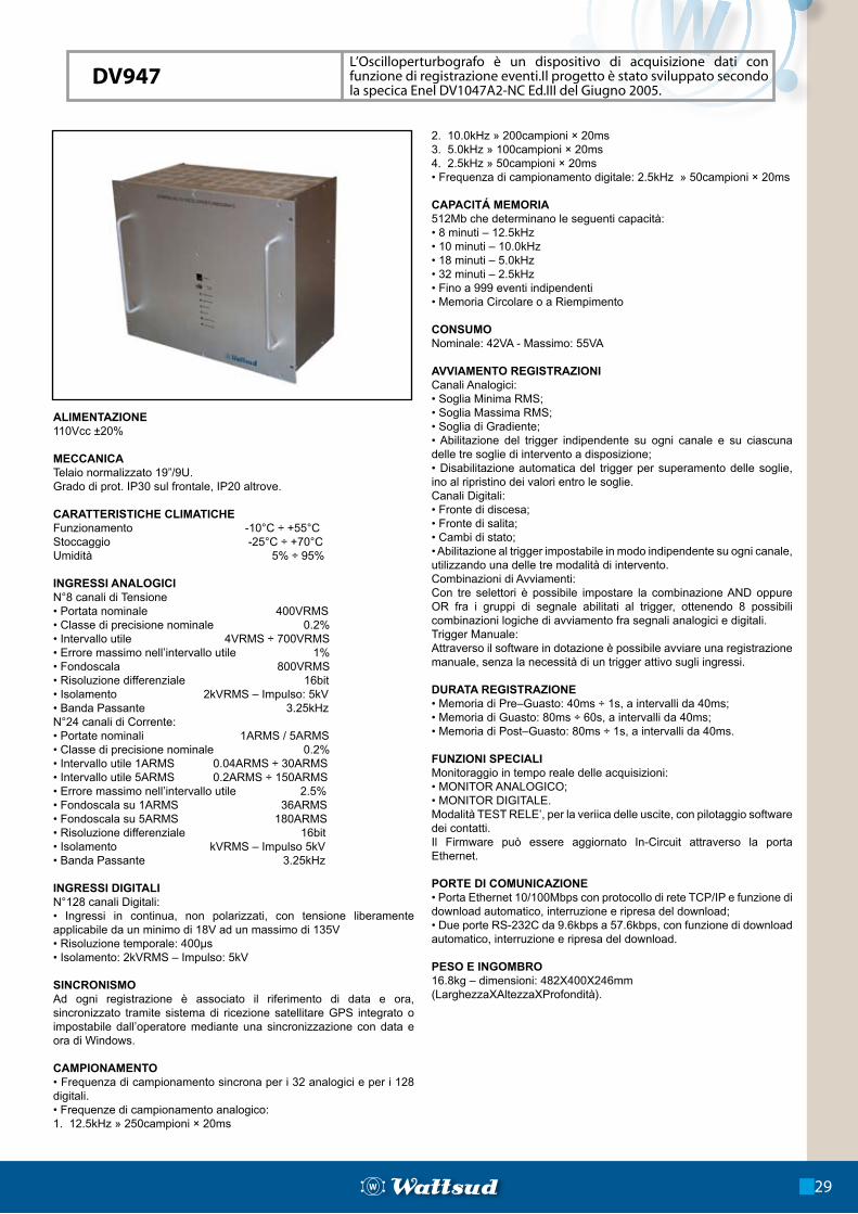
DV947The data fault recorder for primary substations is a data acquisition device with function of recording events. The design has been developed in compliance with ENEL specification DV1047A2-NC Ed.III June 2005.
ALIMENTAZIONE110Vcc ±20%
MECCANICATelaio normalizzato 19”/9U.Grado di prot. IP30 sul frontale, IP20 altrove.
CARATTERISTICHE CLIMATICHEFunzionamento -10°C ÷ +55°CStoccaggio -25°C ÷ +70°CUmidità 5% ÷ 95%
INGRESSI ANALOGICIN°8 canali di Tensione• Portata nominale 400VRMS• Classe di precisione nominale 0.2%• Intervallo utile 4VRMS ÷ 700VRMS• Errore massimo nell’intervallo utile 1%• Fondoscala 800VRMS• Risoluzione differenziale 16bit• Isolamento 2kVRMS – Impulso: 5kV• Banda Passante 3.25kHzN°24 canali di Corrente:• Portate nominali 1ARMS / 5ARMS• Classe di precisione nominale 0.2%• Intervallo utile 1ARMS 0.04ARMS ÷ 30ARMS• Intervallo utile 5ARMS 0.2ARMS ÷ 150ARMS• Errore massimo nell’intervallo utile 2.5%• Fondoscala su 1ARMS 36ARMS• Fondoscala su 5ARMS 180ARMS• Risoluzione differenziale 16bit• Isolamento kVRMS – Impulso 5kV• Banda Passante 3.25kHz
INGRESSI DIGITALIN°128 canali Digitali:• Ingressi in continua, non polarizzati, con tensione liberamente applicabile da un minimo di 18V ad un massimo di 135V• Risoluzione temporale: 400µs• Isolamento: 2kVRMS – Impulso: 5kV
SINCRONISMOAd ogni registrazione è associato il riferimento di data e ora, sincronizzato tramite sistema di ricezione satellitare GPS integrato o impostabile dall’operatore mediante una sincronizzazione con data e ora di Windows.
CAMPIONAMENTO• Frequenza di campionamento sincrona per i 32 analogici e per i 128 digitali.• Frequenze di campionamento analogico:1. 12.5kHz » 250campioni × 20ms
2. 10.0kHz » 200campioni × 20ms3. 5.0kHz » 100campioni × 20ms4. 2.5kHz » 50campioni × 20ms• Frequenza di campionamento digitale: 2.5kHz » 50campioni × 20ms
CAPACITÁ MEMORIA512Mb che determinano le seguenti capacità:• 8 minuti – 12.5kHz• 10 minuti – 10.0kHz• 18 minuti – 5.0kHz• 32 minuti – 2.5kHz• Fino a 999 eventi indipendenti• Memoria Circolare o a Riempimento
CONSUMONominale: 42VA - Massimo: 55VA
AVVIAMENTO REGISTRAZIONI Canali Analogici:• Soglia Minima RMS;• Soglia Massima RMS;• Soglia di Gradiente;• Abilitazione del trigger indipendente su ogni canale e su ciascuna delle tre soglie di intervento a disposizione;• Disabilitazione automatica del trigger per superamento delle soglie, ino al ripristino dei valori entro le soglie.Canali Digitali:• Fronte di discesa;• Fronte di salita;• Cambi di stato;• Abilitazione al trigger impostabile in modo indipendente su ogni canale, utilizzando una delle tre modalità di intervento.Combinazioni di Avviamenti:Con tre selettori è possibile impostare la combinazione AND oppure OR fra i gruppi di segnale abilitati al trigger, ottenendo 8 possibili combinazioni logiche di avviamento fra segnali analogici e digitali.Trigger Manuale:Attraverso il software in dotazione è possibile avviare una registrazione manuale, senza la necessità di un trigger attivo sugli ingressi.
DURATA REGISTRAZIONE• Memoria di Pre–Guasto: 40ms ÷ 1s, a intervalli da 40ms;• Memoria di Guasto: 80ms ÷ 60s, a intervalli da 40ms;• Memoria di Post–Guasto: 80ms ÷ 1s, a intervalli da 40ms.
FUNZIONI SPECIALIMonitoraggio in tempo reale delle acquisizioni:• MONITOR ANALOGICO;• MONITOR DIGITALE.Modalità TEST RELE’, per la veriica delle uscite, con pilotaggio software dei contatti.Il Firmware può essere aggiornato In-Circuit attraverso la porta Ethernet.
PORTE DI COMUNICAZIONE• Porta Ethernet 10/100Mbps con protocollo di rete TCP/IP e funzione di download automatico, interruzione e ripresa del download;• Due porte RS-232C da 9.6kbps a 57.6kbps, con funzione di download automatico, interruzione e ripresa del download.
PESO E INGOMBRO16.8kg – dimensioni: 482X400X246mm (LarghezzaXAltezzaXProfondità).
L’Oscilloperturbografo è un dispositivo di acquisizione dati con funzione di registrazione eventi.Il progetto è stato sviluppato secondo la speci ca Enel DV1047A2-NC Ed.III del Giugno 2005.
29
DV947
POWER SUPPLY9V alkaline batteries, type PP3, model MN1604 in compliance with IEC 6LR61 standard. The battery compartment has degree of protection IP20 for circuits with dangerous voltage. The provided battery assures a recording duration longer than 4 months, when a 6 s measurement interval has been set. Data preservation is limitless since it is based on Flash type non-volatile memories.
SERVICE CONDITIONSOperating temperature: -10 °C ÷ +60 °C.Altitude: from 0 m to 2000 m sea-levelRelative humidity: from 0% to 90%.Environment exposed to saltness and industrial powder.Pollution degree: 2 according to CEI EN 61010-1.
SAFETY REQUIREMENTSIn compliance with Directive 93/68 CEEOvervoltage CAT III 600 V, insulation class 2.
ELECTROMAGNETIC COMPATIBILITYThe device meets the requirements specified in the standards CEI EN 61000-6-3, 61000-6-2, 61326-1.
MEASUREMENT FEATURESThe data logger is provided with one/three current measurement inputs. The calculus of the true root-mean-square (TRMS) is within the following measurement range: 0 A ÷ 2500 A
RMS. The acquisition system
automatically determines the true power line frequency, fitting with it from 47.5 Hz to 52.5 Hz.The device needs about 20 minutes for the warm-up.The error on the measured value is less than or equal to the 0.8% added to the assumed resolution level, which is equal to 2 A
RMS.
The measurement interval is the waiting time between one measure and the next. It can be set by software at a value included between 1 s and 60 s, with a regulation step of 1 s.The device assures recording data memorization for a continuous period of 410 hours, when a 6 s measurement interval has been set.The measurement is accomplished with a sampling rate equal to 1.6 kHz.
MEMORY SETUPMemory setup can be set by software with two options: the circular one and the full-fill one.In the circular option an algorithm is enabled: when the memory is saturated, it partially eliminates the memorized data, replacing them with the data measured at multiple time intervals compared to the previous value. Such management continues until it is manually stopped or until the reaching of the maximum limit for the measurement interval.
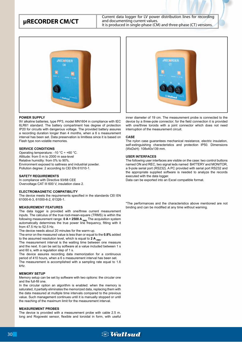
MEASUREMENT PROBESThe device is provided with a measurement probe with cable 2.5 m. long and Rogowski sensor, flexible and toroidal in form, with useful
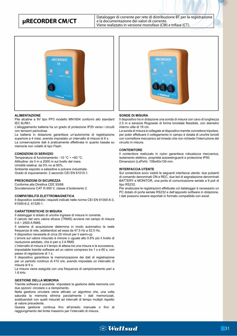
inner diameter of 19 cm. The measurement probe is connected to the device by a three-pole connector; for the field connection it is provided with one/three toroids with a joint connector which does not need interruption of the measurement circuit.
CASEThe nylon case guarantees mechanical resistance, electric insulation, self-extinguishing characteristics and protection IP50. Dimensions (WxDxH): 108x40x139 mm.
USER INTERFACESThe following user interfaces are visible on the case: two control buttons named ON and REC, two signal leds named BATTERY and MONITOR, a 9-pole serial port (RS232). A PC provided with serial port RS232 and the appropriate supplied software is needed to analyze the records executed with the data logger.Data can be exported into an Excel compatible format.
*The performances and the characteristics above mentioned are not binding and can be modified at any time without warning.
30
µRECORDER CM/CTCurrent data logger for LV power distribution lines for recording and documenting current values.It is produced in single-phase (CM) and three-phase (CT) versions.
µRECORDER CM/CT
ALIMENTAZIONEPile alcaline a 9V tipo PP3 modello MN1604 conformi allo standard IEC 6LR61.L’alloggiamento batteria ha un grado di protezione IP20 verso i circuiti con tensioni pericolose.La batteria in dotazione garantisce un’autonomia di registrazione superiore a 4 mesi, avendo impostato un intervallo di misura di 6 s.La conservazione dati è praticamente effettivata in quanto basata su memorie non volatili di tipo Flash.
CONDIZIONI DI SERVIZIOTemperatura di funzionamento: -10 °C ÷ +60 °C.Altitudine: da 0 m a 2000 m sul livello del mare.Umidità relativa: da 0% no al 90%.Ambiente esposto a salsedine e polvere industriale.Grado di inquinamento: 2 secondo CEI EN 61010-1.
PRESCRIZIONI DI SICUREZZAConforme alla Direttiva CEE 93/68.Sovratensione CAT III 600 V, classe d’isolamento 2.
COMPATIBILITÁ ELETTROMAGNETICAIl dispositivo soddisfa i requisiti indicati nelle norme CEI EN 61000-6-3, 61000-6-2, 61326-1.
CARATTERISTICHE DI MISURAIl datalogger è dotato di uno/tre ingressi di misura in corrente.Il calcolo del vero valore ef cace (TRMS) avviene nel campo di misura 0 A ÷ 2500 A RMS.Il sistema di acquisizione determina in modo automatico la reale frequenza di rete, adattandosi ad essa da 47.5 Hz a 52.5 Hz.Il dispositivo necessita di circa 20 minuti per il warm-up.L’errore sul valore misurato è minore o uguale allo 0.8% più il livello di risoluzione adottato, che è pari a 2 A RMS.L’intervallo di misura è il tempo di attesa tra una misura e la successiva, impostabile tramite software ad un valore compreso tra 1 s e 60 s, con passo di regolazione di 1 s.Il dispositivo garantisce la memorizzazione dei dati di registrazione per un periodo continuo di 410 ore, avendo impostato un intervallo di misura di 6 s.La misura viene eseguita con una frequenza di campionamento pari a 1.6 kHz.
GESTIONE DELLA MEMORIATramite software è possibile impostare la gestione della memoria con due opzioni: circolare o a riempimento.Nella gestione circolare viene attivato un algoritmo che, una volta saturata la memoria elimina parzialmente i dati memorizzati, sostituendoli con quelli misurati ad intervalli di tempo multipli rispetto al valore precedente.Questa gestione continua fino all’arresto manuale o fino al raggiungimento del limite massimo per l’intervallo di misura.
SONDE DI MISURAIl dispositivo ha in dotazione una sonda di misura con cavo di lunghezza 2.5 m e sensore Rogowski di forma toroidale flessibile, con diametro interno utile di 19 cm.La sonda di misura è collegate al dispositivo tramite connettore tripolare, per poter effettuare il collegamento in campo è dotata di uno/tre toroidi con connettore meccanico ad innesto che non richiede l’interruzione del circuito in misura.
CONTENITOREIl contenitore realizzato in nylon garantisce robustezza meccanica, isolamento elettrico, proprietà autoestinguenti e protezione IP50.Dimensioni (LxPxH): 108x40x139 mm.
INTERFACCIA UTENTESul contenitore sono visibili le seguenti interfacce utente: due pulsanti di comando denominati ON e REC, due led di segnalazione denominati BATTERY e MONITOR, una porta di comunicazione seriale a 9 poli di tipo RS232.Per analizzare le registrazioni effettuate col datalogger è necessario un PC dotato di porta seriale RS232 e dell’apposito software in dotazione.I dati possono essere esportati in formato compatibile con excel.
Datalogger di corrente per rete di distribuzione BT per la registrazione e la documentazione dei valori di corrente.Viene realizzato in versione monofase (CM) e trifase (CT).
31
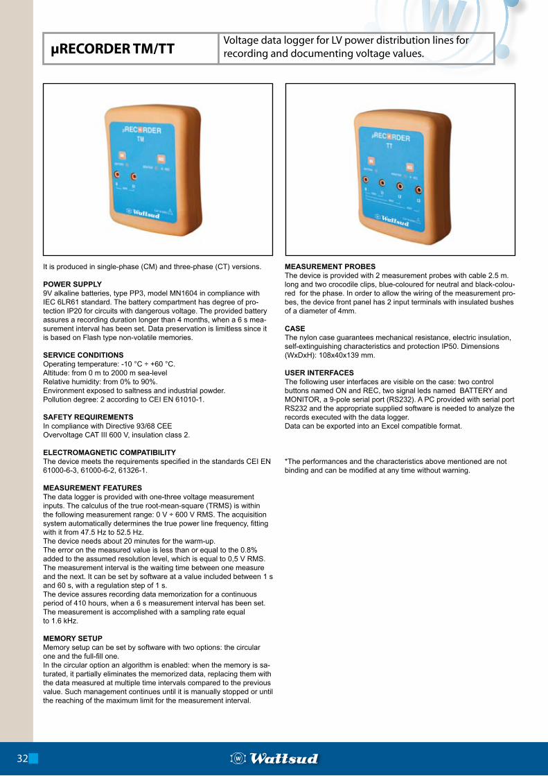
It is produced in single-phase (CM) and three-phase (CT) versions.
POWER SUPPLY9V alkaline batteries, type PP3, model MN1604 in compliance with IEC 6LR61 standard. The battery compartment has degree of pro-tection IP20 for circuits with dangerous voltage. The provided battery assures a recording duration longer than 4 months, when a 6 s mea-surement interval has been set. Data preservation is limitless since it is based on Flash type non-volatile memories.
SERVICE CONDITIONSOperating temperature: -10 °C ÷ +60 °C.Altitude: from 0 m to 2000 m sea-levelRelative humidity: from 0% to 90%.Environment exposed to saltness and industrial powder.Pollution degree: 2 according to CEI EN 61010-1.
SAFETY REQUIREMENTSIn compliance with Directive 93/68 CEEOvervoltage CAT III 600 V, insulation class 2.
ELECTROMAGNETIC COMPATIBILITYThe device meets the requirements specified in the standards CEI EN 61000-6-3, 61000-6-2, 61326-1.
MEASUREMENT FEATURESThe data logger is provided with one-three voltage measurement inputs. The calculus of the true root-mean-square (TRMS) is within the following measurement range: 0 V ÷ 600 V RMS. The acquisition system automatically determines the true power line frequency, fitting with it from 47.5 Hz to 52.5 Hz.The device needs about 20 minutes for the warm-up.The error on the measured value is less than or equal to the 0.8% added to the assumed resolution level, which is equal to 0,5 V RMS.The measurement interval is the waiting time between one measure and the next. It can be set by software at a value included between 1 s and 60 s, with a regulation step of 1 s.The device assures recording data memorization for a continuous period of 410 hours, when a 6 s measurement interval has been set.The measurement is accomplished with a sampling rate equalto 1.6 kHz.
MEMORY SETUPMemory setup can be set by software with two options: the circular one and the full-fill one. In the circular option an algorithm is enabled: when the memory is sa-turated, it partially eliminates the memorized data, replacing them with the data measured at multiple time intervals compared to the previous value. Such management continues until it is manually stopped or until the reaching of the maximum limit for the measurement interval.
MEASUREMENT PROBESThe device is provided with 2 measurement probes with cable 2.5 m. long and two crocodile clips, blue-coloured for neutral and black-colou-red for the phase. In order to allow the wiring of the measurement pro-bes, the device front panel has 2 input terminals with insulated bushes of a diameter of 4mm.
CASEThe nylon case guarantees mechanical resistance, electric insulation, self-extinguishing characteristics and protection IP50. Dimensions (WxDxH): 108x40x139 mm.
USER INTERFACESThe following user interfaces are visible on the case: two control buttons named ON and REC, two signal leds named BATTERY and MONITOR, a 9-pole serial port (RS232). A PC provided with serial port RS232 and the appropriate supplied software is needed to analyze the records executed with the data logger.Data can be exported into an Excel compatible format.
*The performances and the characteristics above mentioned are not binding and can be modified at any time without warning.
32
µRECORDER TM/TTVoltage data logger for LV power distribution lines for recording and documenting voltage values.
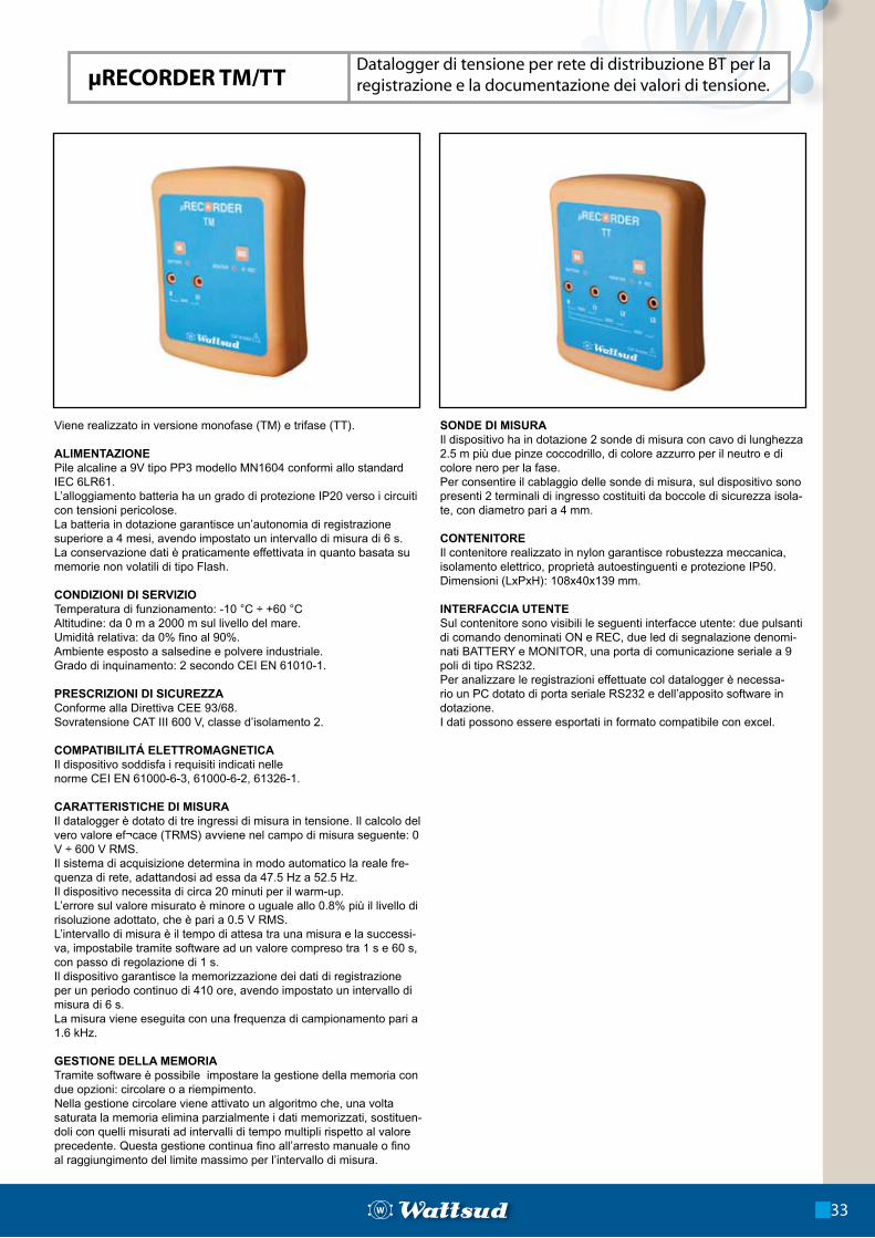
Viene realizzato in versione monofase (TM) e trifase (TT).
ALIMENTAZIONEPile alcaline a 9V tipo PP3 modello MN1604 conformi allo standard IEC 6LR61.L’alloggiamento batteria ha un grado di protezione IP20 verso i circuiti con tensioni pericolose.La batteria in dotazione garantisce un’autonomia di registrazione superiore a 4 mesi, avendo impostato un intervallo di misura di 6 s.La conservazione dati è praticamente effettivata in quanto basata su memorie non volatili di tipo Flash.
CONDIZIONI DI SERVIZIOTemperatura di funzionamento: -10 °C ÷ +60 °CAltitudine: da 0 m a 2000 m sul livello del mare.Umidità relativa: da 0% fino al 90%.Ambiente esposto a salsedine e polvere industriale.Grado di inquinamento: 2 secondo CEI EN 61010-1.
PRESCRIZIONI DI SICUREZZAConforme alla Direttiva CEE 93/68.Sovratensione CAT III 600 V, classe d’isolamento 2.
COMPATIBILITÁ ELETTROMAGNETICAIl dispositivo soddisfa i requisiti indicati nellenorme CEI EN 61000-6-3, 61000-6-2, 61326-1.
CARATTERISTICHE DI MISURAIl datalogger è dotato di tre ingressi di misura in tensione. Il calcolo del vero valore ef¬cace (TRMS) avviene nel campo di misura seguente: 0 V ÷ 600 V RMS.Il sistema di acquisizione determina in modo automatico la reale fre-quenza di rete, adattandosi ad essa da 47.5 Hz a 52.5 Hz.Il dispositivo necessita di circa 20 minuti per il warm-up.L’errore sul valore misurato è minore o uguale allo 0.8% più il livello di risoluzione adottato, che è pari a 0.5 V RMS.L’intervallo di misura è il tempo di attesa tra una misura e la successi-va, impostabile tramite software ad un valore compreso tra 1 s e 60 s, con passo di regolazione di 1 s.Il dispositivo garantisce la memorizzazione dei dati di registrazione per un periodo continuo di 410 ore, avendo impostato un intervallo di misura di 6 s.La misura viene eseguita con una frequenza di campionamento pari a 1.6 kHz.
GESTIONE DELLA MEMORIATramite software è possibile impostare la gestione della memoria con due opzioni: circolare o a riempimento.Nella gestione circolare viene attivato un algoritmo che, una volta saturata la memoria elimina parzialmente i dati memorizzati, sostituen-doli con quelli misurati ad intervalli di tempo multipli rispetto al valore precedente. Questa gestione continua fino all’arresto manuale o fino al raggiungimento del limite massimo per l’intervallo di misura.
SONDE DI MISURAIl dispositivo ha in dotazione 2 sonde di misura con cavo di lunghezza 2.5 m più due pinze coccodrillo, di colore azzurro per il neutro e di colore nero per la fase.Per consentire il cablaggio delle sonde di misura, sul dispositivo sono presenti 2 terminali di ingresso costituiti da boccole di sicurezza isola-te, con diametro pari a 4 mm.
CONTENITOREIl contenitore realizzato in nylon garantisce robustezza meccanica, isolamento elettrico, proprietà autoestinguenti e protezione IP50.Dimensioni (LxPxH): 108x40x139 mm.
INTERFACCIA UTENTESul contenitore sono visibili le seguenti interfacce utente: due pulsanti di comando denominati ON e REC, due led di segnalazione denomi-nati BATTERY e MONITOR, una porta di comunicazione seriale a 9 poli di tipo RS232.Per analizzare le registrazioni effettuate col datalogger è necessa-rio un PC dotato di porta seriale RS232 e dell’apposito software in dotazione.I dati possono essere esportati in formato compatibile con excel.
Datalogger di tensione per rete di distribuzione BT per la registrazione e la documentazione dei valori di tensione.
33
µRECORDER TM/TT
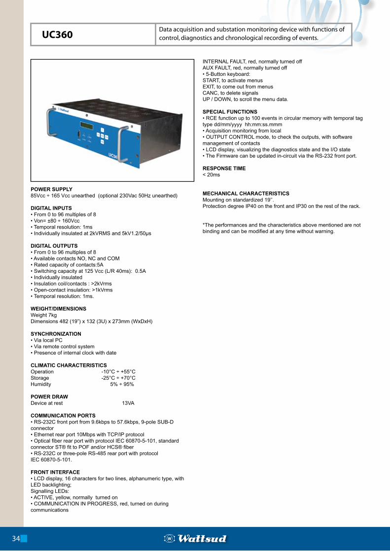
POWER SUPPLY85Vcc ÷ 165 Vcc unearthed (optional 230Vac 50Hz unearthed)
DIGITAL INPUTS• From 0 to 96 multiples of 8• Von= ±80 ÷ 160Vcc• Temporal resolution: 1ms• Individually insulated at 2kVRMS and 5kV1.2/50µs
DIGITAL OUTPUTS• From 0 to 96 multiples of 8• Available contacts NO, NC and COM• Rated capacity of contacts:5A• Switching capacity at 125 Vcc (L/R 40ms): 0.5A• Individually insulated• Insulation coil/contacts : >2kVrms• Open-contact insulation: >1kVrms• Temporal resolution: 1ms.
WEIGHT/DIMENSIONSWeight 7kgDimensions 482 (19”) x 132 (3U) x 273mm (WxDxH)
SYNCHRONIZATION• Via local PC• Via remote control system• Presence of internal clock with date
CLIMATIC CHARACTERISTICSOperation -10°C ÷ +55°CStorage -25°C ÷ +70°CHumidity 5% ÷ 95%
POWER DRAWDevice at rest 13VA
COMMUNICATION PORTS• RS-232C front port from 9.6kbps to 57.6kbps, 9-pole SUB-D connector• Ethernet rear port 10Mbps with TCP/IP protocol• Optical fiber rear port with protocol IEC 60870-5-101, standardconnector ST® fit to POF and/or HCS® fiber• RS-232C or three-pole RS-485 rear port with protocolIEC 60870-5-101.
FRONT INTERFACE• LCD display, 16 characters for two lines, alphanumeric type, with LED backlighting;Signalling LEDs:• ACTIVE, yellow, normally turned on• COMMUNICATION IN PROGRESS, red, turned on during communications
INTERNAL FAULT, red, normally turned offAUX FAULT, red, normally turned off• 5-Button keyboard:START, to activate menusEXIT, to come out from menusCANC, to delete signalsUP / DOWN, to scroll the menu data.
SPECIAL FUNCTIONS • RCE function up to 100 events in circular memory with temporal tag type dd/mm/yyyy hh:mm:ss.mmm• Acquisition monitoring from local• OUTPUT CONTROL mode, to check the outputs, with software management of contacts• LCD display, visualizing the diagnostics state and the I/O state• The Firmware can be updated in-circuit via the RS-232 front port.
RESPONSE TIME< 20ms
MECHANICAL CHARACTERISTICS Mounting on standardized 19’’.Protection degree IP40 on the front and IP30 on the rest of the rack.
*The performances and the characteristics above mentioned are not binding and can be modified at any time without warning.
34
UC360Data acquisition and substation monitoring device with functions of control, diagnostics and chronological recording of events.
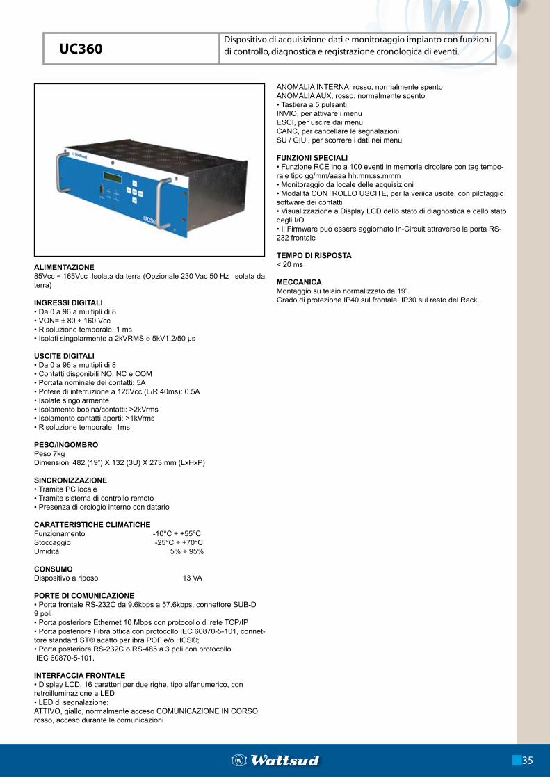
ALIMENTAZIONE85Vcc ÷ 165Vcc Isolata da terra (Opzionale 230 Vac 50 Hz Isolata da terra)
INGRESSI DIGITALI• Da 0 a 96 a multipli di 8• VON= ± 80 ÷ 160 Vcc• Risoluzione temporale: 1 ms• Isolati singolarmente a 2kVRMS e 5kV1.2/50 µs
USCITE DIGITALI• Da 0 a 96 a multipli di 8• Contatti disponibili NO, NC e COM• Portata nominale dei contatti: 5A• Potere di interruzione a 125Vcc (L/R 40ms): 0.5A• Isolate singolarmente• Isolamento bobina/contatti: >2kVrms• Isolamento contatti aperti: >1kVrms• Risoluzione temporale: 1ms.
PESO/INGOMBROPeso 7kgDimensioni 482 (19”) X 132 (3U) X 273 mm (LxHxP)
SINCRONIZZAZIONE• Tramite PC locale• Tramite sistema di controllo remoto• Presenza di orologio interno con datario
CARATTERISTICHE CLIMATICHEFunzionamento -10°C ÷ +55°CStoccaggio -25°C ÷ +70°CUmidità 5% ÷ 95%
CONSUMODispositivo a riposo 13 VA
PORTE DI COMUNICAZIONE• Porta frontale RS-232C da 9.6kbps a 57.6kbps, connettore SUB-D 9 poli• Porta posteriore Ethernet 10 Mbps con protocollo di rete TCP/IP• Porta posteriore Fibra ottica con protocollo IEC 60870-5-101, connet-tore standard ST® adatto per ibra POF e/o HCS®;• Porta posteriore RS-232C o RS-485 a 3 poli con protocollo IEC 60870-5-101.
INTERFACCIA FRONTALE• Display LCD, 16 caratteri per due righe, tipo alfanumerico, con retroilluminazione a LED• LED di segnalazione:ATTIVO, giallo, normalmente acceso COMUNICAZIONE IN CORSO, rosso, acceso durante le comunicazioni
ANOMALIA INTERNA, rosso, normalmente spentoANOMALIA AUX, rosso, normalmente spento• Tastiera a 5 pulsanti:INVIO, per attivare i menuESCI, per uscire dai menuCANC, per cancellare le segnalazioniSU / GIU’, per scorrere i dati nei menu
FUNZIONI SPECIALI• Funzione RCE ino a 100 eventi in memoria circolare con tag tempo-rale tipo gg/mm/aaaa hh:mm:ss.mmm• Monitoraggio da locale delle acquisizioni• Modalità CONTROLLO USCITE, per la veriica uscite, con pilotaggio software dei contatti• Visualizzazione a Display LCD dello stato di diagnostica e dello stato degli I/O• Il Firmware può essere aggiornato In-Circuit attraverso la porta RS-232 frontale
TEMPO DI RISPOSTA< 20 ms
MECCANICAMontaggio su telaio normalizzato da 19”.Grado di protezione IP40 sul frontale, IP30 sul resto del Rack.
Dispositivo di acquisizione dati e monitoraggio impianto con funzioni di controllo, diagnostica e registrazione cronologica di eventi.
35
UC360

WATTSUD - Lavorazioni Elettromeccaniche di Precisione S.p.A.80020 Casavatore ( Napoli) Italy - Viale G. Marconi, 191/C tel. +39 081 7050311 fax +39 081 7050327
[email protected] - www.wattsud.it
CE
R T I F I E
D
Q
UA L I T Y S Y S TEM
CE
R T I F I E
D
Q
UA L I T Y S Y S TEM