HRA DOMO - Innova Energie€¦ · 9 N420230A_ManualHRA DOMO_Rev3.EN.docx 1.1.9 DESCRIPTION OF...
52
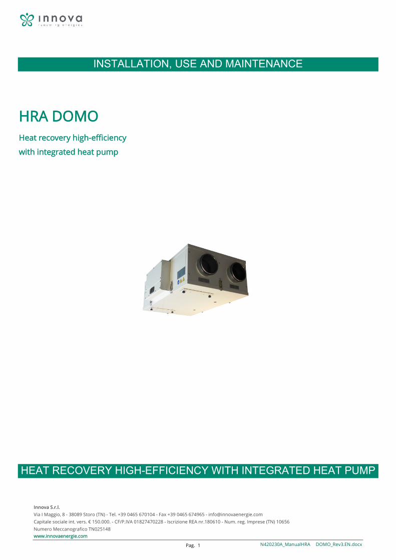
Innova S.r.l. Via I Maggio, 8 - 38089 Storo (TN) - Tel. +39 0465 670104 - Fax +39 0465 674965 - [email protected] Capitale sociale int. vers. € 150.000. - CF/P.IVA 01827470228 - Iscrizione REA nr.180610 - Num. reg. Imprese (TN) 10656 Numero Meccanografico TN025148 www.innovaenergie.com Pag. 1 N420230A_ManualHRA DOMO_Rev3.EN.docx INSTALLATION, USE AND MAINTENANCE HRA DOMO Heat recovery high-efficiency with integrated heat pump HEAT RECOVERY HIGH-EFFICIENCY WITH INTEGRATED HEAT PUMP
Transcript of HRA DOMO - Innova Energie€¦ · 9 N420230A_ManualHRA DOMO_Rev3.EN.docx 1.1.9 DESCRIPTION OF...
Innova S.r.l. Via I Maggio, 8 - 38089 Storo (TN) - Tel. +39 0465 670104 - Fax +39 0465 674965 - [email protected] Capitale sociale int. vers. € 150.000. - CF/P.IVA 01827470228 - Iscrizione REA nr.180610 - Num. reg. Imprese (TN) 10656 Numero Meccanografico TN025148 www.innovaenergie.com Pag. 1 N420230A_ManualHRA DOMO_Rev3.EN.docx
INSTALLATION, USE AND MAINTENANCE
HRA DOMO Heat recovery high-efficiency
with integrated heat pump
HEAT RECOVERY HIGH-EFFICIENCY WITH INTEGRATED HEAT PUMP
Innova S.r.l. Pag. 2 N420230A_ManualHRA DOMO_Rev3.EN.docx
INDEX
1 GENERALITY ...................................................................................................................................................................................... 4
1.1.1 INTRODUCTION ................................................................................................................................................................... 4
1.1.2 SAFETY RULES ..................................................................................................................................................... 4
1.1.3 SYMBOLOGY ........................................................................................................................................................................ 5
1.1.4 WARNINGS .......................................................................................................................................................................... 6
1.1.5 CONFORMITY ...................................................................................................................................................................... 7
1.1.6 RANGE ................................................................................................................................................................................. 7
1.1.7 IDENTIFICATION .......................................................................................................................................................... 7
1.1.8 CONSTRUCTION FEATURES ................................................................................................................................................. 8
1.1.9 DESCRIPTION OF OPERATION ............................................................................................................................................. 9
1.1.10 DELIVERY STATE .............................................................................................................................................................. 9
1.1.11 REQUIREMENTS FOR STARTING ........................................................................................................................ 9
1.1.12 REMOVAL AND DISPOSAL ................................................................................................................................ 9
2 INSTALLATION ................................................................................................................................................................................. 10
2.1.1 INSTALLATION CONDITIONS ................................................................................................................................. 10
2.1.2 POSITIONING UNIT ................................................................................................................................................. 11
2.1.3 DRAIN CONNECTION .......................................................................................................................................... 11
3 AREAULICI CONNECTIONS ............................................................................................................................................................... 12
3.1.1 GUIDELINES AREAULICI ........................................................................................................................................ 12
4 ELECTRICAL CONNECTIONS ............................................................................................................................................................. 13
4.1.1 GENERALITY .......................................................................................................................................................... 13
4.1.2 WIRING UNIT ..................................................................................................................................................................... 14
4.1.3 ELECTRICAL CONNECTIONS VERSION -E- ............................................................................................................ 17
5 INSTALLATION EXTERNAL BATTERY ................................................................................................................................................ 20
Innova S.r.l. Pag. 3 N420230A_ManualHRA DOMO_Rev3.EN.docx
5.1.1 ELECTRIC BATTERY ....................................................................................................................................... 20
5.1.2 HYDRONIC BATTERIES .................................................................................................................................. 21
6 COMMISSIONING AND METHOD FOR USE ..................................................................................................................................... 22
6.1.1 GENERALITY ........................................................................................................................................................ 22
6.1.2 WORKING VERSION -E- PANEL THIS REMOTE ................................................................................................................... 22
6.1.3 WORKING VERSION -E- REMOTE PANEL VISIOGRAPH TGF ............................................................................................... 26
6.1.4 CONTROL PANEL - DISPLAY PROBE ................................................................................................................................... 28
6.1.5 CONTROL PANEL - CHANGE SET POINT ............................................................................................................................. 28
6.1.6 WORKING VERSION -E- REMOTE PANEL VISIOGRAPH TNF ............................................................................................... 36
7 MAINTENANCE ................................................................................................................................................................................ 47
7.1.1 CLEANING OR REPLACING FILTERS .................................................................................................................................... 47
7.1.2 CLEANING THE COOLER ..................................................................................................................................................... 47
7.1.3 GENERAL CLEANING UNIT ' ............................................................................................................................................... 48
8 ALARMS ........................................................................................................................................................................................... 49
8.1.1 GENERALITY' ...................................................................................................................................................................... 49
8.1.2 PROBLEMS WITHOUT ERROR INDICATION ON DISPLAY ................................................................................................... 49
8.1.3 TABLE ALARMS REPORTED TO DISPLAY ............................................................................................................................ 50
9 NOTES AND INFORMATION SERVICE .............................................................................................................................................. 51
NOTE ............................................................................................................................................................................................... 51
Innova S.r.l. Pag. 4 N420230A_ManualHRA DOMO_Rev3.EN.docx
1 GENERALITY
1.1.1 INTRODUCTION
This manual has been designed with the aim to make it as easy as possible the installation and management of your plant.
By reading and applying the tips in this manual, you can get the best performance of the product purchased.
We would like to thank you for your choice with the purchase of our product.
Please read this file before making any operation on 'units.
You should not install the unit, perform on it any work, if haven’t not thoroughly read and understood this manual in
all its parts. In particular, you must take all the precautions listed in the manual.
The documentation supplied must be delivered to the person responsible who should keep it carefully (at least 10 years) for future assistance, maintenance and repairs.
The installation of the unit must take into account both the purely technical requirements for the proper functioning, as well as any local legislation
force that the requirements specifications.
Ensure the delivery of the unit, there are no obvious signs of damage in transit. In this case, indicate on the delivery note.
This manual reflects the state of the art at the time of commercialization of the machine and can not be considered inadequate because later updated according to new experiences. The Manufacturer reserves the right to update products and manuals, without any obligation to the previous update, except in exceptional cases.
Contact the Sales Department of the manufacturer for further information or technical documentation updates and to suggest any improvements in this manual. All reports received will be strictly scrutinized.
1.1.2 SAFETY RULES
Recall that the use of products that use electricity and water requires the observance of some fundamental safety rules:
• The use of equipment to disabled people and non-assisted is prohibited
• It is forbidden to touch the appliance barefoot or with wet or damp body
• It is prohibited any operation of cleaning, before disconnecting the appliance from the power supply by placing the mains switch in the off
• It is forbidden to modify the safety or adjustment devices without authorization and instructions from the manufacturer
• Do not pull, detach or twist the electrical cables coming from the unit, even when disconnected from the power network.
• It is forbidden to introduce objects and substances through the intake grilles and air flow.
• It is forbidden to open the doors of access to the internal parts of the appliance, without having first placed the main switch of' plant on off.
• It is forbidden to disperse and leave within reach of children of the' packing material as it can be potentially dangerous.
• Observe the safety distances between the machine and other equipment or structures to ensure a sufficient drive access space for maintenance and service operations as described in this booklet.
Innova S.r.l. Pag. 5 N420230A_ManualHRA DOMO_Rev3.EN.docx
• The unit power supply must be made with electrical cables with a suitable section of the power unit. The voltage and frequency values must correspond to those indicated for the respective machines; All units must be earthed in compliance with current legislation in the different countries.
• -Do not enter R134 in the atmosphere: the R134A is a fluorinated greenhouse gas, called the Kyoto Protocol, with a Global Warming Potential (GWP)
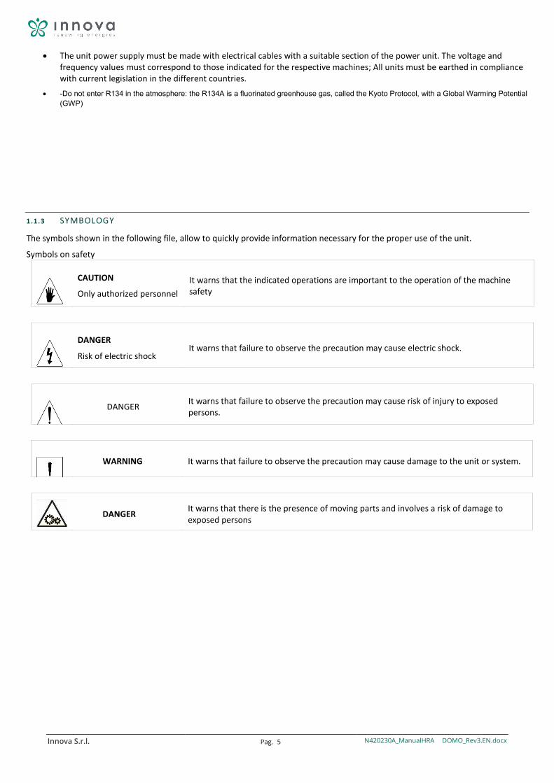
1.1.3 SYMBOLOGY
The symbols shown in the following file, allow to quickly provide information necessary for the proper use of the unit.
Symbols on safety
CAUTION
Only authorized personnel It warns that the indicated operations are important to the operation of the machine safety
DANGER
Risk of electric shock It warns that failure to observe the precaution may cause electric shock.
DANGER It warns that failure to observe the precaution may cause risk of injury to exposed persons.
WARNING It warns that failure to observe the precaution may cause damage to the unit or system.
DANGER It warns that there is the presence of moving parts and involves a risk of damage to
exposed persons
Innova S.r.l. Pag. 6 N420230A_ManualHRA DOMO_Rev3.EN.docx
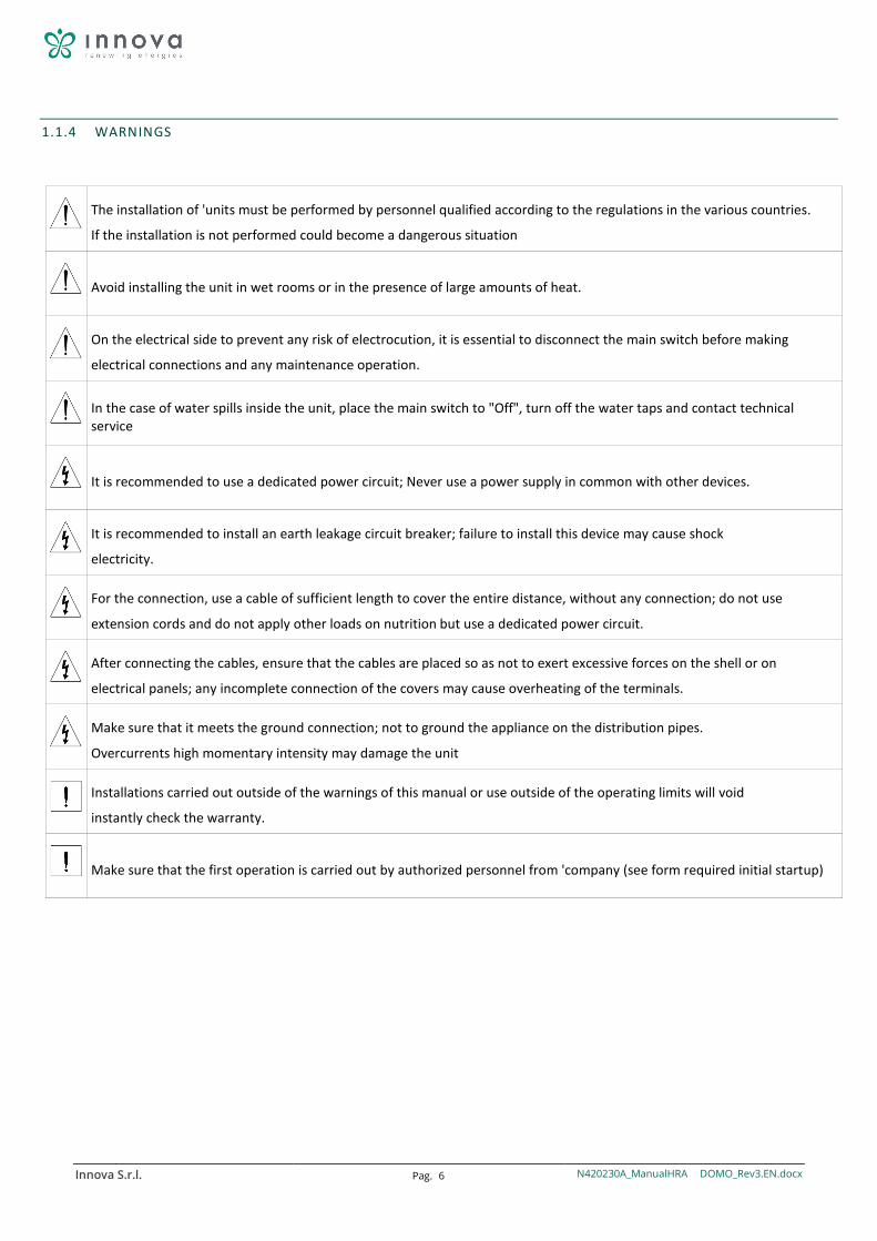
1.1.4 WARNINGS
The installation of 'units must be performed by personnel qualified according to the regulations in the various countries.
If the installation is not performed could become a dangerous situation
Avoid installing the unit in wet rooms or in the presence of large amounts of heat.
On the electrical side to prevent any risk of electrocution, it is essential to disconnect the main switch before making
electrical connections and any maintenance operation.
In the case of water spills inside the unit, place the main switch to "Off", turn off the water taps and contact technical service
It is recommended to use a dedicated power circuit; Never use a power supply in common with other devices.
It is recommended to install an earth leakage circuit breaker; failure to install this device may cause shock
electricity.
For the connection, use a cable of sufficient length to cover the entire distance, without any connection; do not use
extension cords and do not apply other loads on nutrition but use a dedicated power circuit.
After connecting the cables, ensure that the cables are placed so as not to exert excessive forces on the shell or on
electrical panels; any incomplete connection of the covers may cause overheating of the terminals.
Make sure that it meets the ground connection; not to ground the appliance on the distribution pipes.
Overcurrents high momentary intensity may damage the unit
Installations carried out outside of the warnings of this manual or use outside of the operating limits will void
instantly check the warranty.
Make sure that the first operation is carried out by authorized personnel from 'company (see form required initial startup)
Innova S.r.l. Pag. 7 N420230A_ManualHRA DOMO_Rev3.EN.docx
1.1.5 CONFORMITY
The CE marking (present on every machine) attesting conformity with the following European standards:
• machinery Directive 2006/42 / EC
• Low Voltage Directive 2014/35 / EC
• Electromagnetic Compatibility Directive 2014/30 / EC
• Ecodesign 2009/125 / EC
1.1.6 RANGE
-1- -2-
80 S
(1) Defines the maximum flow rate
Models: 80 Mc / 300 Mc / h
2) Type of installation
S: Heating / Cooling
W: With Heat Recovery ACS
1.1.7 IDENTIFICATION
-The unit is identifiable through the label on the front panel of the same lower.
-On the package will be an additional nameplate with the unit's model and shipping references.
The plaque on the ackaging has no significance for the traceability of the product in the years following the sale.
The excision, the deterioration and the illegibility of the nameplate on the unit, involves great problems in the identification of the machine, in the availability of spare parts, and then in all its future maintenance.
Innova S.r.l. Pag. 8 N420230A_ManualHRA DOMO_Rev3.EN.docx
1.1.8 CONSTRUCTION FEATURES
ALL IN ONE: Complete unit capable of changing the air and incorporate thermal cooling requirements in the areas served. The unit is complete with all parts for its operation and ready for use.
SECTION OF RECOVERY: Exchanger polypropylene cross-flow counter-current with high efficiency.
Low freezing and operating temperatures up to -25 °.
Very high transfer efficiency
VENTILATION: Centrifugal fans with backward curved blades, with directly brushless
directly coupled.
ACTIVE THERMODYNAMIC RECOVERY: The unit allows passive and active recovery exhaust air energy. The thermodynamic recovery allows thanks to its refrigerant circuit to provide energy to the environment in higher quantities than subtracted from the ventilation.
FILTER: Upstream of the recuperator is present a F7 on the air filter inlet and a filter F7
on the air of a low pressure drop ejection.
STRUCTURE: sheet metal self-supporting frame
Sandwich panels of galvanized sheet metal, painted externally, with interposed polystyrene insulation, interior rear-end collisions in thick galvanized sheet metal.
COOLING CIRCUIT: Made of copper brazed complete: High-efficiency compressor, dehydrator filter,
finned coils, solenoids, valves, electronic expansion valve, liquid receiver, pressure transducers and safety devices.
SETTING: Electric panel on board unit with microprocessor and dedicated adjustment. Management of the fans, viewing of internal machine temperature probes, management dirty filters timed.
Management defrost algorithm optimized for operation with low internal temperatures.
Large graphic interface with configuration menus and multi-language user menu.
Prepared for MODBUS RTU RS 485 with a wide variety of home automation systems.
Innova S.r.l. Pag. 9 N420230A_ManualHRA DOMO_Rev3.EN.docx
1.1.9 DESCRIPTION OF OPERATION
The unit is a ventilation system with heat recovery by the following characteristics and features:
It promotes a healthy ventilation inside of the housing, allowing the correct air change of the environments and extracting excess moisture and odors;
allows a considerable energy saving for heating thanks to the efficiency of the heat recovery greater than 90%;
The class F7 filters, low pressure loss, guarantee the outside air filtering, fundamental for people with allergies;
the electronic speed control motors, guarantee a low consumption of electricity;
thermal and acoustic insulation;
Inspection and maintenance of easy access by panel fasteners;
antifreeze protection;
control unit with display;
predisposition for easy connection to the network and the remote control;
Also available with integrated bypass
1.1.10 DELIVERY STATE
The supply includes:
Full recovery unit of fans installed inside the unit
countercurrent heat exchanger in polypropylene pre-inserted inside the unit;
2 F7 class filters pre-inserted inside the unit;
Electrical box with predisposition connection terminal;
4 ceiling mounting brackets
exhaust kit condensate composed by siphon and internal threaded pipe;
labels / stickers (safety pictograms, identification air attacks, CE marking ...) already positioned on the unit.
Installation, use and maintenance
1.1.11 REQUIREMENTS FOR STARTING
Before starting make sure there are no foreign objects inside the unit.
Check the hardware of the closing panels and doors of inspections.
If there are no channels installed on one of the aeraulic 4 outlets, provide adequate protection to install a network.
Check the power supply and the grounding of the unit.
1.1.12 REMOVAL AND DISPOSAL
Do not disassemble or dispose of the product yourself. The disassembly, demolition, disposal of the product must be performed by authorized personnel in accordance with local regulations.
Innova S.r.l. Pag. 10 N420230A_ManualHRA DOMO_Rev3.EN.docx
2 INSTALLATION
2.1.1 INSTALLATION CONDITIONS
The unit must be installed according to national and local rules governing the use of electrical devices and according to the following guidelines:
- install the unit within residential buildings with ambient temperature between 0 ° C and 45 ° C;
- avoid areas in close proximity to sources of heat, steam, flammable and / or explosive and particularly dusty areas;
- install the unit in a place not subject to frost (the condensation water must be discharged not frozen, at a certain inclination, using a siphon);
- not install the unit in areas with a high relative humidity (such as the bathroom or toilet) to avoid condensation on the outer surface;
- choose an installation place where there is enough space around the unit for the air ducts and connections in order to perform maintenance;
- the consistency of the ceiling / wall / floor where the unit will be installed must be adapted to the weight of the unit and does not cause vibrations.
In the environment chosen for the installation must be present:
- connections of the air ducts;
- single-phase electrical connection 230V
- connection for the condensate discharge.
The unit is an integral part of a balanced ventilation system, with which the contaminated air is extracted from the kitchen, bathroom or any other local and introducing the same volume of fresh air in the living room or in the bedrooms. Gaps under the doors ensure a good circulation of air flow inside the home: make sure these gaps are never obstructed, such as para drafts or carpets, otherwise the system will not work optimally.
The simultaneous operation of the unit and a natural draft boiler (for example, Open fireplace) may cause a depression in the environment, which may occur due to a backflow of exhaust gas into the environment.
Innova S.r.l. Pag. 11 N420230A_ManualHRA DOMO_Rev3.EN.docx
2.1.2 POSITIONING UNIT
VERSION H - Ceiling mount
For ceiling mounting unit, you must:
Place the 4 mounting brackets on the rear side of the unit and fix it with the screws supplied, after having carried out the holes with a drill (the holes must be drilled on the frame);
Attach to the ceiling unit, via the brackets, using appropriate anchoring systems (dowels, threaded rods, chains ...) and check the leveling with the aid of a spirit level.
Ensuring sufficient space for the performance of maintenance tasks: it must be guaranteed the opening of the cover of the unit (from the bottom).
Not mount the unit with the hips in direct contact with the walls to avoid possible noises from contact, insert strips of rubber or neoprene in this case.
Ceiling mount Brackets for ceiling mounting
2.1.3 DRAIN CONNECTION
Because of the heat recovery system (the hot exhaust air is cooled by placing inside the heat exchanger), the moisture contained in the indoor air will condense inside the unit.
For the proper functioning of the heat exchanger, it is therefore necessary to connect a condensate drain to the hydraulic system (exhaust) of the house. In addition, to enable the correct outflow of the condensate water, and avoid air eddies, the condensate drain must always be provided OF THE SPECIAL siphon supplied (on version V) units; on the H versions the installer to install a siphon;
To install the exhaust condensation adhere to the following standards:
• give a slope of at least 2% to the exhaust pipe;
• provide for the possibility to disconnect the drain pipe for maintenance (in particular in the case of ceiling installation);
• make sure that the discharge end of the tube is at least below the water level of the siphon;
• make sure that the siphon is always full of water.
Install the siphon condensate discharge of the unit ejection to avoid unpleasant odors in ambient air
Innova S.r.l. Pag. 12 N420230A_ManualHRA DOMO_Rev3.EN.docx
3 AREAULICI CONNECTIONS
3.1.1 GUIDELINES AREAULICI
The unit is equipped with 4 male circulated attacks of different diameter depending on the size: for optimum operation.
For the correct connection of the air ducts, refer to the following diagram and the places adhesives unit.
Table diameters aeraulici connections units
Size 080 140 200 300
Ø mm 125 125 160 160
We recommend installing at least 500mm of flexible tubing to avoid dragging the vibration or noise caused by installation.
According to the plant in which the unit must be installed, it will be possible to suitably orient the four aeraulici attacks.
Below any possible configurations:
Innova S.r.l. Pag. 13 N420230A_ManualHRA DOMO_Rev3.EN.docx
CONFIGURATION VERSION HORIZONTAL H
Unit view from above
4 ELECTRICAL CONNECTIONS
4.1.1 GENERALITY
-First starting any operation to make the electrical connection to make sure that the unit is not electrically supplied
-Perform electrical connections required exclusively by consulting the wiring diagram attached to this manual.
-Install a suitable interrupt and protection device to exclusive service differential unit.
-it is essential that the unit is connected to an efficient earth plug. The manufacturer refuses all responsibility for the non-observance of this
precaution.
-Make that the electrical components selected for the installation (main switch, circuit breakers, cables and terminal section) are suitable for
installed unit electrical power and which take account of the compressor inrush currents as well as the maximum attainable load.
The related data are indicated on the wiring diagram and on the unit nameplate
-E 'forbidden to enter the electrical wiring in the unit except where specified in this booklet.
-Use cables and electrical conductors of appropriate sections and comply with current regulations of the various countries.
-Avoid absolutely to pass the electric cables in direct contact with pipes or components within the unit
-Verify after the first moments of operation the tightening of the screws of the power terminals
Innova S.r.l. Pag. 14 N420230A_ManualHRA DOMO_Rev3.EN.docx
Table for the dimensioning of the power line
Size 080 140 200 300
Maximum current absorbed TO 0.26 0.34 0.5 0.91
4.1.2 WIRING UNIT
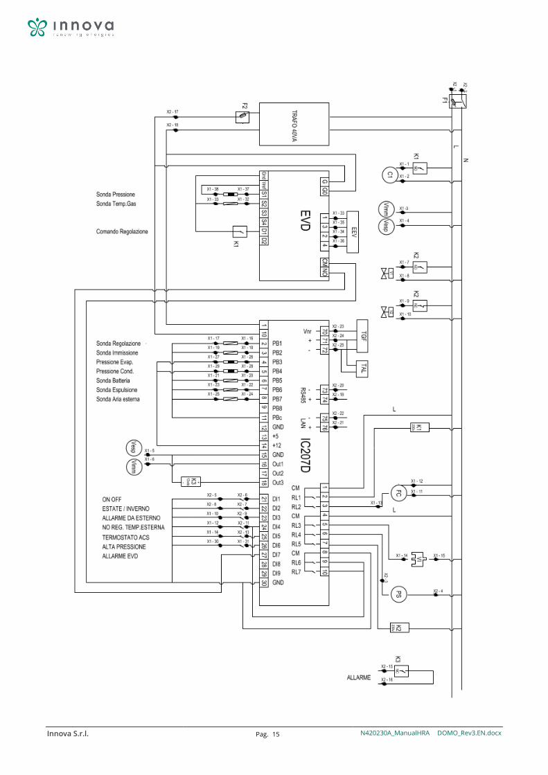
Innova S.r.l. Pag. 15 N420230A_ManualHRA DOMO_Rev3.EN.docx
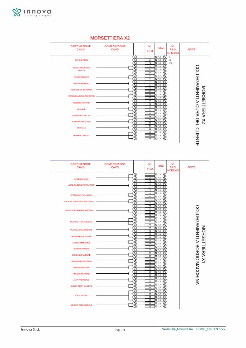
Innova S.r.l. Pag. 16 N420230A_ManualHRA DOMO_Rev3.EN.docx
Innova S.r.l. Pag. 17 N420230A_ManualHRA DOMO_Rev3.EN.docx
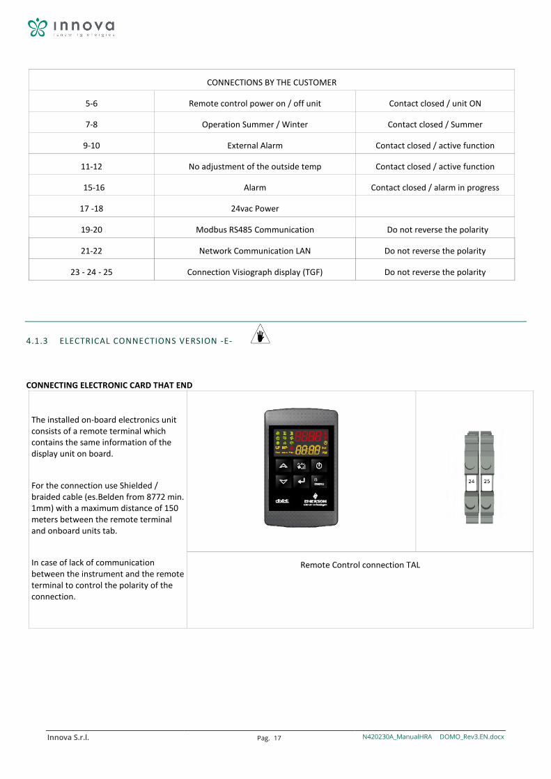
CONNECTIONS BY THE CUSTOMER
5-6 Remote control power on / off unit Contact closed / unit ON
7-8 Operation Summer / Winter Contact closed / Summer
9-10 External Alarm Contact closed / active function
11-12 No adjustment of the outside temp Contact closed / active function
15-16 Alarm Contact closed / alarm in progress
17 -18 24vac Power
19-20 Modbus RS485 Communication Do not reverse the polarity
21-22 Network Communication LAN Do not reverse the polarity
23 - 24 - 25 Connection Visiograph display (TGF) Do not reverse the polarity
4.1.3 ELECTRICAL CONNECTIONS VERSION -E-
CONNECTING ELECTRONIC CARD THAT END
The installed on-board electronics unit consists of a remote terminal which contains the same information of the display unit on board.
For the connection use Shielded / braided cable (es.Belden from 8772 min. 1mm) with a maximum distance of 150 meters between the remote terminal and onboard units tab.
In case of lack of communication between the instrument and the remote terminal to control the polarity of the connection.
Remote Control connection TAL
Innova S.r.l. Pag. 18 N420230A_ManualHRA DOMO_Rev3.EN.docx
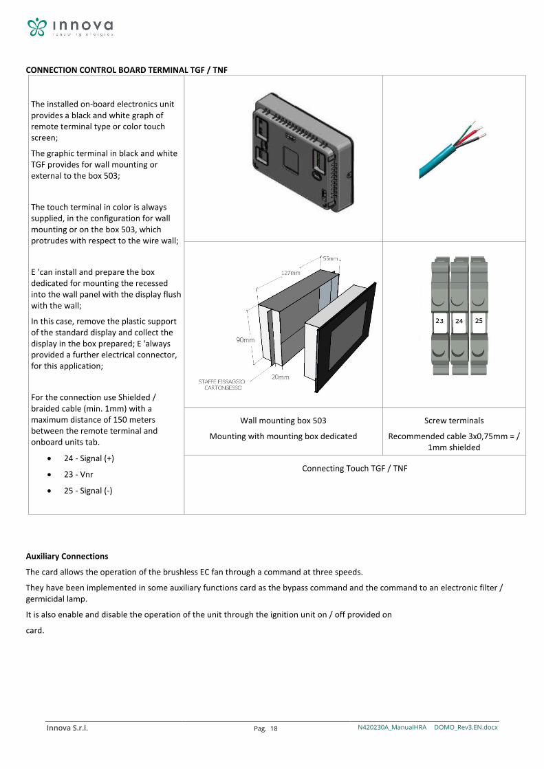
CONNECTION CONTROL BOARD TERMINAL TGF / TNF
The installed on-board electronics unit provides a black and white graph of remote terminal type or color touch screen;
The graphic terminal in black and white TGF provides for wall mounting or external to the box 503;
The touch terminal in color is always supplied, in the configuration for wall mounting or on the box 503, which protrudes with respect to the wire wall;
E 'can install and prepare the box dedicated for mounting the recessed into the wall panel with the display flush with the wall;
In this case, remove the plastic support of the standard display and collect the display in the box prepared; E 'always provided a further electrical connector, for this application;
For the connection use Shielded / braided cable (min. 1mm) with a maximum distance of 150 meters between the remote terminal and onboard units tab.
• 24 - Signal (+)
• 23 - Vnr
• 25 - Signal (-)
Wall mounting box 503
Mounting with mounting box dedicated
Screw terminals
Recommended cable 3x0,75mm = / 1mm shielded
Connecting Touch TGF / TNF
Auxiliary Connections
The card allows the operation of the brushless EC fan through a command at three speeds.
They have been implemented in some auxiliary functions card as the bypass command and the command to an electronic filter / germicidal lamp.
It is also enable and disable the operation of the unit through the ignition unit on / off provided on
card.
Innova S.r.l. Pag. 19 N420230A_ManualHRA DOMO_Rev3.EN.docx
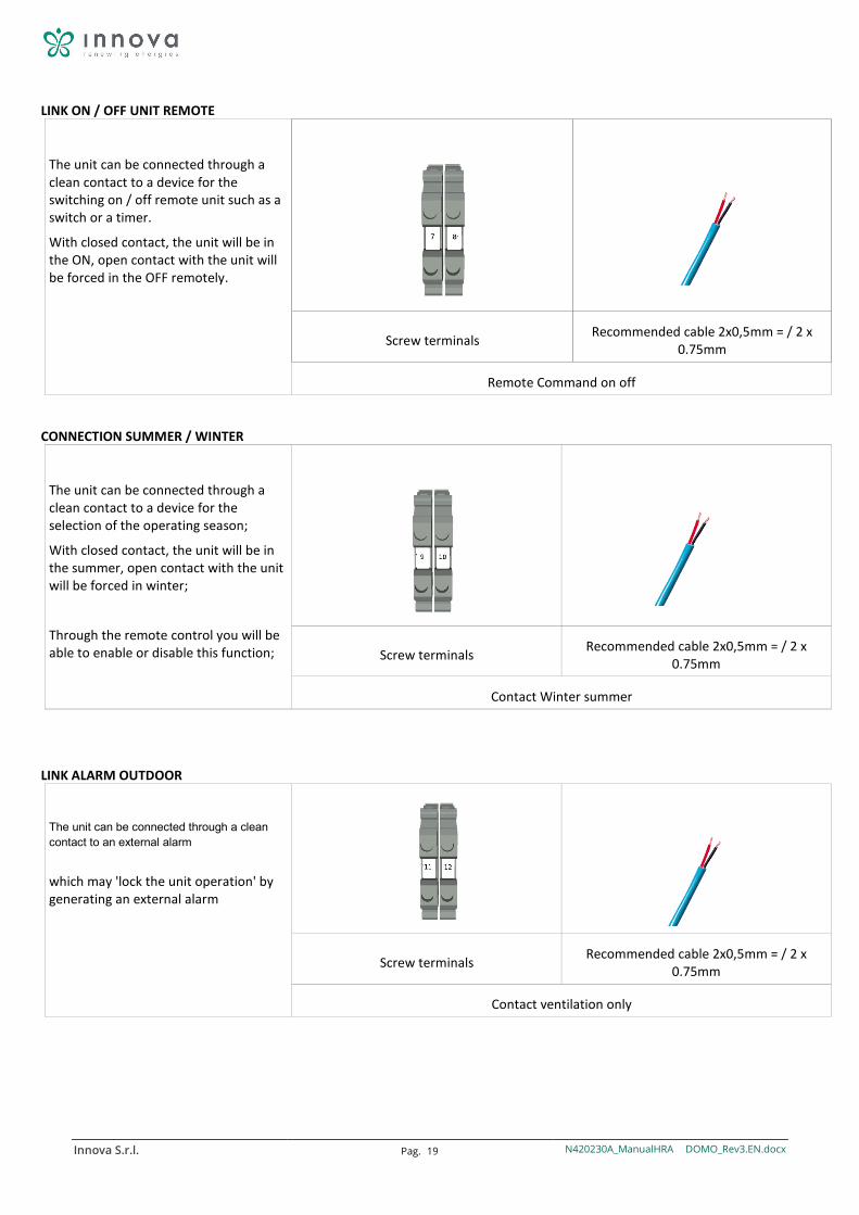
LINK ON / OFF UNIT REMOTE
The unit can be connected through a clean contact to a device for the switching on / off remote unit such as a switch or a timer.
With closed contact, the unit will be in the ON, open contact with the unit will be forced in the OFF remotely.
Screw terminals Recommended cable 2x0,5mm = / 2 x 0.75mm
Remote Command on off
CONNECTION SUMMER / WINTER
The unit can be connected through a clean contact to a device for the selection of the operating season;
With closed contact, the unit will be in the summer, open contact with the unit will be forced in winter;
Through the remote control you will be able to enable or disable this function;
Screw terminals Recommended cable 2x0,5mm = / 2 x 0.75mm
Contact Winter summer
LINK ALARM OUTDOOR
The unit can be connected through a clean contact to an external alarm
which may 'lock the unit operation' by generating an external alarm
Screw terminals Recommended cable 2x0,5mm = / 2 x 0.75mm
Contact ventilation only
Innova S.r.l. Pag. 20 N420230A_ManualHRA DOMO_Rev3.EN.docx
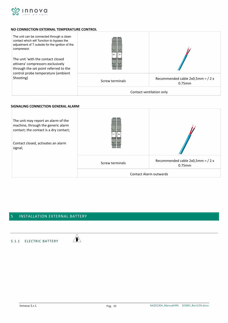
NO CONNECTION EXTERNAL TEMPERATURE CONTROL
The unit can be connected through a clean contact which will 'function to bypass the adjustment of T.outside for the ignition of the compressor.
The unit 'with the contact closed attivera' compressors exclusively through the set point referred to the control probe temperature (ambient Shooting)
Screw terminals Recommended cable 2x0,5mm = / 2 x 0.75mm
Contact ventilation only
SIGNALING CONNECTION GENERAL ALARM
The unit may report an alarm of the machine, through the generic alarm contact; the contact is a dry contact;
Contact closed, activates an alarm signal;
Screw terminals Recommended cable 2x0,5mm = / 2 x 0.75mm
Contact Alarm outwards
5 INSTALLATION EXTERNAL BATTERY
5.1.1 ELECTRIC BATTERY
Innova S.r.l. Pag. 21 N420230A_ManualHRA DOMO_Rev3.EN.docx
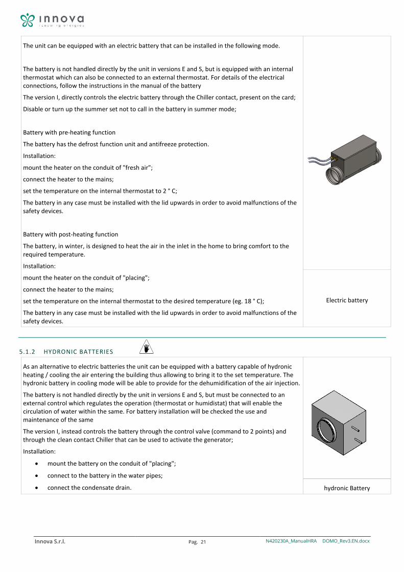
The unit can be equipped with an electric battery that can be installed in the following mode.
The battery is not handled directly by the unit in versions E and S, but is equipped with an internal thermostat which can also be connected to an external thermostat. For details of the electrical connections, follow the instructions in the manual of the battery
The version I, directly controls the electric battery through the Chiller contact, present on the card;
Disable or turn up the summer set not to call in the battery in summer mode;
Battery with pre-heating function
The battery has the defrost function unit and antifreeze protection.
Installation:
mount the heater on the conduit of "fresh air";
connect the heater to the mains;
set the temperature on the internal thermostat to 2 ° C;
The battery in any case must be installed with the lid upwards in order to avoid malfunctions of the safety devices.
Battery with post-heating function
The battery, in winter, is designed to heat the air in the inlet in the home to bring comfort to the required temperature.
Installation:
mount the heater on the conduit of "placing";
connect the heater to the mains;
set the temperature on the internal thermostat to the desired temperature (eg. 18 ° C);
The battery in any case must be installed with the lid upwards in order to avoid malfunctions of the safety devices.
Electric battery
5.1.2 HYDRONIC BATTERIES
As an alternative to electric batteries the unit can be equipped with a battery capable of hydronic heating / cooling the air entering the building thus allowing to bring it to the set temperature. The hydronic battery in cooling mode will be able to provide for the dehumidification of the air injection.
The battery is not handled directly by the unit in versions E and S, but must be connected to an external control which regulates the operation (thermostat or humidistat) that will enable the circulation of water within the same. For battery installation will be checked the use and maintenance of the same
The version I, instead controls the battery through the control valve (command to 2 points) and through the clean contact Chiller that can be used to activate the generator;
Installation:
• mount the battery on the conduit of "placing";
• connect to the battery in the water pipes;
• connect the condensate drain.
hydronic Battery
Innova S.r.l. Pag. 22 N420230A_ManualHRA DOMO_Rev3.EN.docx
6 COMMISSIONING AND METHOD FOR USE
6.1.1 GENERALITY
To ensure the "discharge" moisture that is created naturally within the dwelling, the unit must operate continuously at least at a reduced speed (speed 1). If you turn off the ventilation unit, you might encounter condensation inside the machine and inside the building with possible damage due to moisture.
The operation of the unit and the possible changing of the factory settings must be carried out only by qualified personnel (authorized installer).
6.1.2 WORKING VERSION -E- PANEL THIS REMOTE
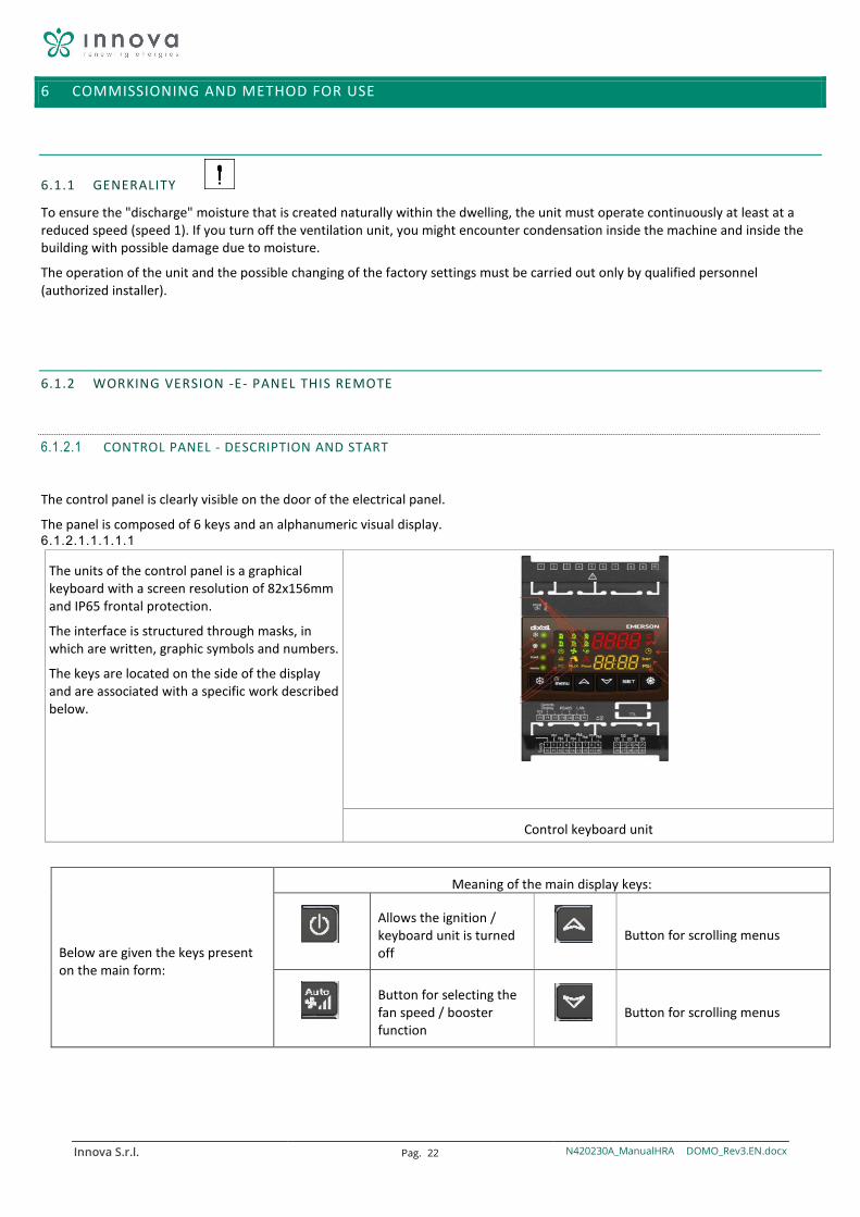
6.1.2.1 CONTROL PANEL - DESCRIPTION AND START
The control panel is clearly visible on the door of the electrical panel.
The panel is composed of 6 keys and an alphanumeric visual display. 6.1.2.1.1.1.1.1
The units of the control panel is a graphical keyboard with a screen resolution of 82x156mm and IP65 frontal protection.
The interface is structured through masks, in which are written, graphic symbols and numbers.
The keys are located on the side of the display and are associated with a specific work described below.
Control keyboard unit
Below are given the keys present on the main form:
Meaning of the main display keys:
Allows the ignition / keyboard unit is turned off
Button for scrolling menus
Button for selecting the fan speed / booster function
Button for scrolling menus
Innova S.r.l. Pag. 23 N420230A_ManualHRA DOMO_Rev3.EN.docx
Send key to confirm
the choices
Button to access the menu functions
Viewing the main mask keys
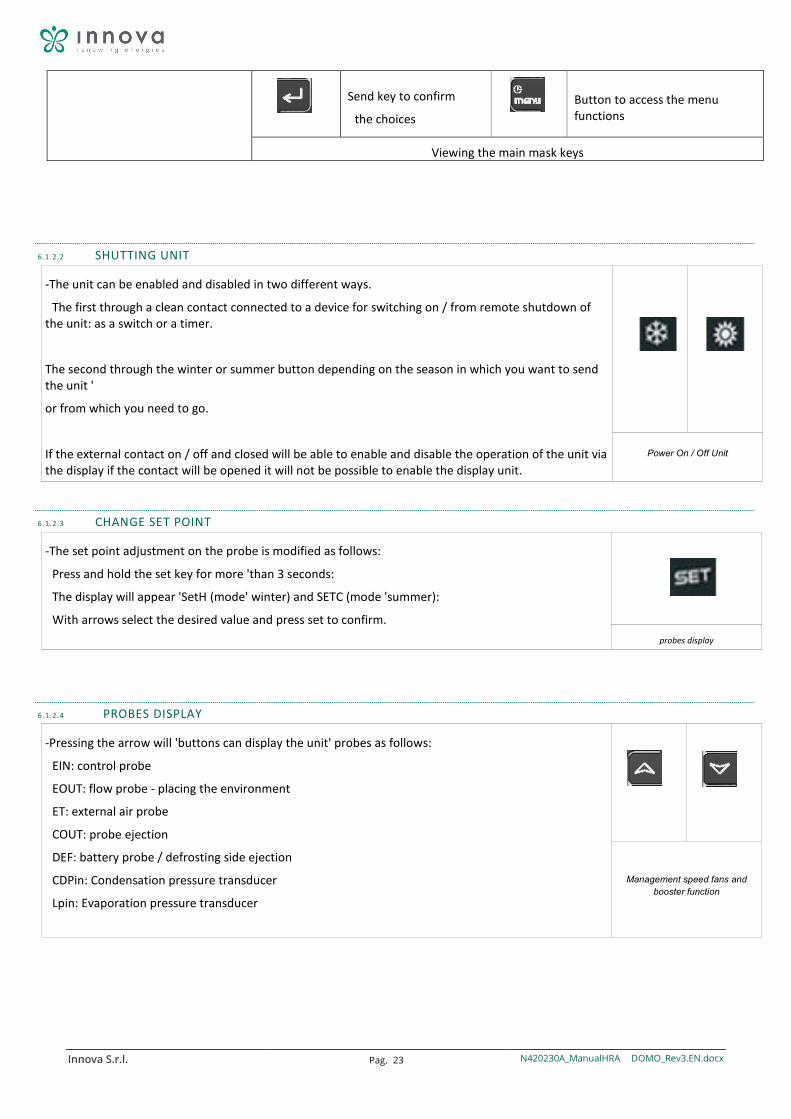
6.1.2.2 SHUTTING UNIT
-The unit can be enabled and disabled in two different ways.
The first through a clean contact connected to a device for switching on / from remote shutdown of the unit: as a switch or a timer.
The second through the winter or summer button depending on the season in which you want to send the unit '
or from which you need to go.
If the external contact on / off and closed will be able to enable and disable the operation of the unit via the display if the contact will be opened it will not be possible to enable the display unit.
Power On / Off Unit
6.1.2.3 CHANGE SET POINT
-The set point adjustment on the probe is modified as follows:
Press and hold the set key for more 'than 3 seconds:
The display will appear 'SetH (mode' winter) and SETC (mode 'summer):
With arrows select the desired value and press set to confirm.
probes display
6.1.2.4 PROBES DISPLAY
-Pressing the arrow will 'buttons can display the unit' probes as follows:
EIN: control probe
EOUT: flow probe - placing the environment
ET: external air probe
COUT: probe ejection
DEF: battery probe / defrosting side ejection
CDPin: Condensation pressure transducer
Lpin: Evaporation pressure transducer
Management speed fans and booster function
Innova S.r.l. Pag. 24 N420230A_ManualHRA DOMO_Rev3.EN.docx
6.1.2.5 MENU 'FUNCTIONS (UNITED DISPLAY, ALARM, ALARM LOG ETC.)
Enter into the function menu (press "menu" key) as the ability to: • Select the work mode (ModE) • Display sensor values (Pb) • Show and reset the alarms (ALrM) • Display and clear the alarm history (ALOG) • Load the instrument on key parameters (UPL) • Display the percentage of proportional operation of the outputs for controlling the speed of renewal fans and ejection
(OUT)
were viewing
6.1.2.6 ALARMS IN PROGRESS - MENU 'FUNCTIONS
Once in the function menu with the arrow up or down Alrm display the sub-menu and confirm with enter:
- With the UP or DOWN keys to select the function ALrM - Press the Enter key (if not the enter key pressure no alarm is present is not enabled) - The lower display shows the label with the alarm code, the upper display the rSt label if the alarm can be
reset, NO label if it is not resettable - Scroll all alarms UP or DOWN - Pressing the enter key in correspondence with the label rSt allows the alarm is reset and the transition to
the next; even if this is resettable by pressing the enter key, the alarm is reset and the next alarm is displayed. Pressing the enter key in the presence of a non-resettable alarm (NO label) does not allow resetting the same.
- To exit ALrM press the MENU button or wait the time time -out
Visualizzaione alarms in progress
6.1.2.7 DISPLAY FAULT - MENU 'FUNCTIONS
If an alarm occurs the device records the alarm code; the last recorded alarm is stored with progressive index higher. Once in the function menu with the arrow up or down alog display the sub-menu and confirm with enter:
1. the lower display shows the alarm label and the upper display shows the label "n" followed by sequential number from 00 to 99
2. if more alarms pressing the UP and DOWN buttons have occurred to view them
The exit from ALOG menu you by pressing the MENU button or time - out.
Visualizzaione historical alarms
6.1.2.8 CLEAR FAULT - MENU 'FUNCTIONS
The procedure to delete the alarm log is as follows. Once in the function menu with the arrow up or down alog display the sub-menu and confirm with enter:
1. scroll through the alarms with the UP or DOWN keys until you see the label "ArSt" lower display; the upper display shows the label "PAS"
2. Press the Enter key; the lower display shows the label "PAS" and the upper display the digit "0" flashing. Enter the password value using the "UP" and "DOWN"; if the value of the password is correct, the label "ArSt" flashes for 5 sec, and the historian is deleted, if the value of the password is not correct you will see the label "PAS" in the lower display and the digit "0" in the upper display
The exit from ALOG menu you by pressing the MENU button or time - out.
The alarms are stored in memory 100; each additional alarm that will be detected at above this number, automatically delete the oldest alarm in memory.
Erase Fault List
Innova S.r.l. Pag. 25 N420230A_ManualHRA DOMO_Rev3.EN.docx
6.1.2.9 DISPLAY OF FANS WORK PERCENTAGE - MENU FUNCTIONS
The procedure to display in the menu functions of the proportional outputs work percentages is as follows. Once in the function menu with the arrow up or down display the sub-menu and confirm with enter Out
fans work percentage Displaying
6.1.2.10 EDIT MODE FANS
The procedure for changing the speed 'of ventilation are: -Keep pressing for more' than 3/2 set and arrow with downward direction: -on the display will appear 'Pr1 - PAS Enter the password using the arrow keys (default value 1)
Scroll with the arrows to the family of parameters US: US 51 - speed fans in the summer with compressor ON US 57 - fan speed in winter with compressor ON US 59 - fan speed in free cooling US 60 - fan speed in ventilation only
To change the values press set, select the value with the arrow keys and confirm with SET. To exit the 'PR1 parameter menu press menu' until it reaches the insertion password, and then simultaneously press and arrow set with the upward direction.
fans work percentage Displaying
6.1.2.11 CHANGE SET POINT AND FUNCTION SETTING WITH FRESH AIR
The standard unit is configured with dual adjustment function for compressor activation.
The adjustment will be as follows: The unit activates the compressors only if they are in demand - the set point referred to the adjustment as indicated in the previous paragraph - the set point referred to the external air probe as described below
If both will not be in the adjustment request, the unit is going to operate in ventilation only. - Press and hold for more than 3 seconds set and DOWN arrow: - Pr1 – PAS will appear on the display
- Enter the password with the arrows (standard value 1) Scroll with the arrows up to the US parameter family: US 8 – Set Point Outdoor winter air US 15 – Outdoor summer air Set point
For example: If in winter the adjustment set point is at 20 ° the probe reads 16 °, the Unit should be activated with the compressor. But if the outside temperature is not below the US8 value the unit will still go in ventilation only. To exit the menu parameters PR1 Press Menu until the password insertion is reached and then press set and arrow with upward direction at the same time.
fans work percentage Displaying
Innova S.r.l. Pag. 26 N420230A_ManualHRA DOMO_Rev3.EN.docx
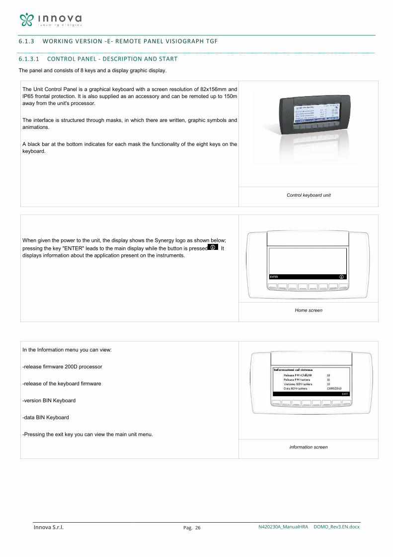
6.1.3 WORKING VERSION -E- REMOTE PANEL VISIOGRAPH TGF
6.1.3.1 CONTROL PANEL - DESCRIPTION AND START
The panel and consists of 8 keys and a display graphic display.
The Unit Control Panel is a graphical keyboard with a screen resolution of 82x156mm and IP65 frontal protection. It is also supplied as an accessory and can be remoted up to 150m away from the unit's processor.
The interface is structured through masks, in which there are written, graphic symbols and animations.
A black bar at the bottom indicates for each mask the functionality of the eight keys on the keyboard.
Control keyboard unit
When given the power to the unit, the display shows the Synergy logo as shown below; pressing the key "ENTER" leads to the main display while the button is pressed It displays information about the application present on the instruments.
Home screen
In the Information menu you can view:
-release firmware 200D processor
-release of the keyboard firmware
-version BIN Keyboard
-data BIN Keyboard
-Pressing the exit key you can view the main unit menu.
information screen
Innova S.r.l. Pag. 27 N420230A_ManualHRA DOMO_Rev3.EN.docx
6.1.3.2 CONTROL PANEL - MASK HOME
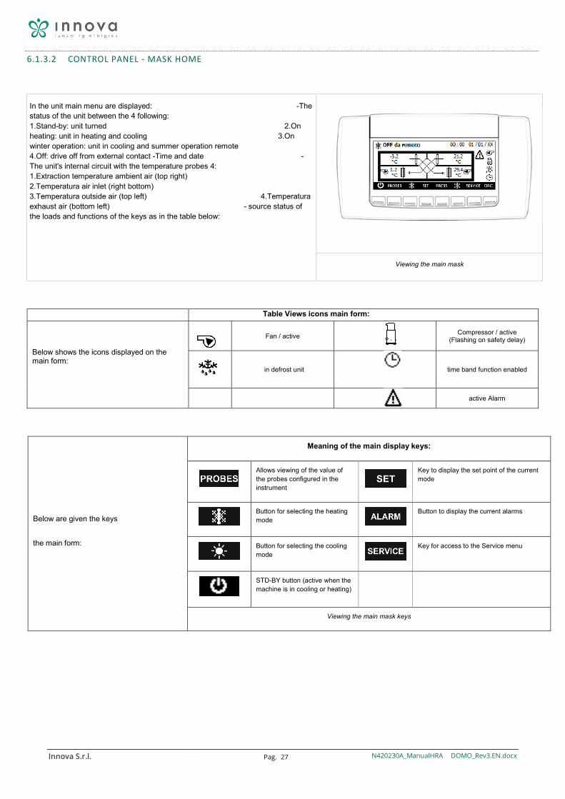
In the unit main menu are displayed: -The status of the unit between the 4 following: 1.Stand-by: unit turned 2.On heating: unit in heating and cooling 3.On winter operation: unit in cooling and summer operation remote 4.Off: drive off from external contact -Time and date -The unit's internal circuit with the temperature probes 4: 1.Extraction temperature ambient air (top right) 2.Temperatura air inlet (right bottom) 3.Temperatura outside air (top left) 4.Temperatura exhaust air (bottom left) - source status of the loads and functions of the keys as in the table below:
Viewing the main mask
Table Views icons main form: Below shows the icons displayed on the main form:
Fan / active
Compressor / active
(Flashing on safety delay)
in defrost unit time band function enabled
active Alarm
Below are given the keys
the main form:
Meaning of the main display keys:
Allows viewing of the value of the probes configured in the instrument
Key to display the set point of the current mode
Button for selecting the heating mode
Button to display the current alarms
Button for selecting the cooling mode
Key for access to the Service menu
STD-BY button (active when the machine is in cooling or heating)
Viewing the main mask keys
Innova S.r.l. Pag. 28 N420230A_ManualHRA DOMO_Rev3.EN.docx
6.1.4 CONTROL PANEL - DISPLAY PROBE
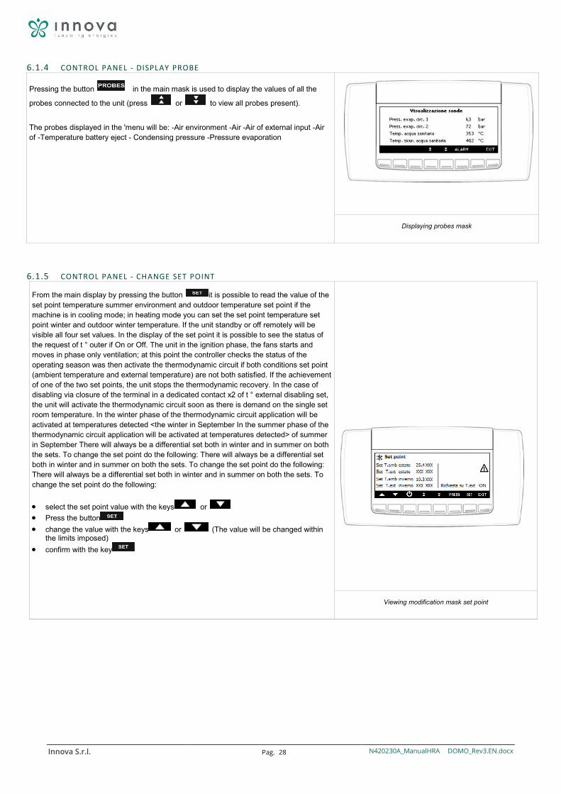
Pressing the button in the main mask is used to display the values of all the
probes connected to the unit (press or to view all probes present).
The probes displayed in the 'menu will be: -Air environment -Air -Air of external input -Air of -Temperature battery eject - Condensing pressure -Pressure evaporation
Displaying probes mask
6.1.5 CONTROL PANEL - CHANGE SET POINT
From the main display by pressing the button it is possible to read the value of the set point temperature summer environment and outdoor temperature set point if the machine is in cooling mode; in heating mode you can set the set point temperature set point winter and outdoor winter temperature. If the unit standby or off remotely will be visible all four set values. In the display of the set point it is possible to see the status of the request of t ° outer if On or Off. The unit in the ignition phase, the fans starts and moves in phase only ventilation; at this point the controller checks the status of the operating season was then activate the thermodynamic circuit if both conditions set point (ambient temperature and external temperature) are not both satisfied. If the achievement of one of the two set points, the unit stops the thermodynamic recovery. In the case of disabling via closure of the terminal in a dedicated contact x2 of t ° external disabling set, the unit will activate the thermodynamic circuit soon as there is demand on the single set room temperature. In the winter phase of the thermodynamic circuit application will be activated at temperatures detected <the winter in September In the summer phase of the thermodynamic circuit application will be activated at temperatures detected> of summer in September There will always be a differential set both in winter and in summer on both the sets. To change the set point do the following: There will always be a differential set both in winter and in summer on both the sets. To change the set point do the following: There will always be a differential set both in winter and in summer on both the sets. To change the set point do the following:
• select the set point value with the keys or • Press the button • change the value with the keys or (The value will be changed within
the limits imposed) • confirm with the key
Viewing modification mask set point
Innova S.r.l. Pag. 29 N420230A_ManualHRA DOMO_Rev3.EN.docx
6.1.5.1 CONTROL PANEL - DISPLAY AND ALARM RESET
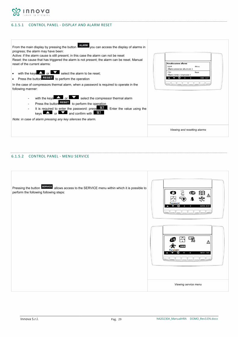
From the main display by pressing the button you can access the display of alarms in progress; the alarm may have been: Active: if the alarm cause is still present; in this case the alarm can not be reset Reset: the cause that has triggered the alarm is not present; the alarm can be reset. Manual reset of the current alarms:
• with the keys or select the alarm to be reset; • Press the button to perform the operation
In the case of compressors thermal alarm, when a password is required to operate in the following manner:
- with the keys or select the compressor thermal alarm - Press the button to perform the operation - It is required to enter the password: press , Enter the value using the
keys or and confirm with
Note: in case of alarm pressing any key silences the alarm.
Viewing and resetting alarms
6.1.5.2 CONTROL PANEL - MENU SERVICE
Pressing the button allows access to the SERVICE menu within which it is possible to perform the following following steps:
Viewing service menu
Innova S.r.l. Pag. 30 N420230A_ManualHRA DOMO_Rev3.EN.docx
Table service menu icons Views: Below shows the icons displayed on the main form:
Factory Menu
Alarm history Menu
Clock Menu
Defrost Menu
Compressor Menu
Inputs / outputs Menu
Fans Menu
Menu time slots
Circuits Menu
Menu Upload and Download software
Current alarms Menu
Input Menu and Display
installation menu
6.1.5.3 CONTROL PANEL - MENU FACTORY
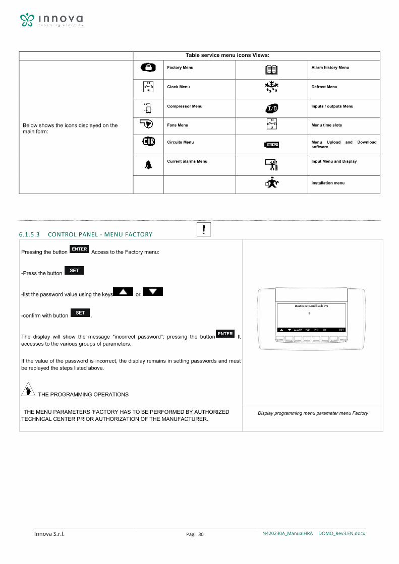
Pressing the button Access to the Factory menu:
-Press the button
-list the password value using the keys or
-confirm with button .
The display will show the message "incorrect password"; pressing the button It accesses to the various groups of parameters.
If the value of the password is incorrect, the display remains in setting passwords and must be replayed the steps listed above.
THE PROGRAMMING OPERATIONS
THE MENU PARAMETERS 'FACTORY HAS TO BE PERFORMED BY AUTHORIZED TECHNICAL CENTER PRIOR AUTHORIZATION OF THE MANUFACTURER.
Display programming menu parameter menu Factory
Innova S.r.l. Pag. 31 N420230A_ManualHRA DOMO_Rev3.EN.docx
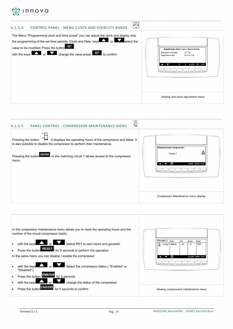
6.1.5.4 CONTROL PANEL - MENU CLOCK AND VISIBILITY BANDS
The Menu "Programming clock and time zones" you can adjust the clock and display only
the programming of the set time periods. Clock and Date: keys or select the
value to be modified; Press the button
with the keys or change the value press to confirm
Viewing and clock adjustment menu
6.1.5.5 PANEL CONTROL - COMPRESSOR MAINTENANCE MENU
Pressing the button It displays the operating hours of the compressor and ideas. It is also possible to disable the compressor to perform their maintenance.
Pressing the button in the matching circuit 1 allows access to the compressor menu.
Compressor Maintenance menu display
In the compressor maintenance menu allows you to reset the operating hours and the number of the circuit compressor starts:
• with the keys or Select RST to zero hours and goodwill;
• Press the button for 5 seconds to perform the operation In the same menu you can disable / enable the compressor:
• with the keys or Select the compressor status ( "Enabled" or "Disabled");
• Press the button for 5 seconds
• with the keys or change the status of the compressor
• Press the button for 5 seconds to confirm
Viewing compressors maintenance menu
Innova S.r.l. Pag. 32 N420230A_ManualHRA DOMO_Rev3.EN.docx
6.1.5.6 CONTROL PANEL - MAINTENANCE MENU FANS
In compressors maintenance menu allows you to reset the operating hours and the number of ignitions of each of the circuit fan:
• with the keys or select RTD in correspondence with the value of which you want to reset the hours of operation;
• Press the button for 5 seconds to perform the operation
fans maintenance menu display
6.1.5.7 CONTROL PANEL - MENU COOLING CIRCUITS
Through circuits menu you can view the interior cooling circuit state with ability to disable it for maintenance.
with the keys or select the value to be modified;
Press the button
with the keys or change the value press to confirm
cooling circuits menu display
6.1.5.8 CONTROL PANEL - MENU ALARMS IN PROGRESS
By using the buttons or you can view all the alarms in progress; the alarm may have been: Active: if the alarm cause is still present; in this case the alarm can not be reset Reset: the cause that has triggered the alarm is not present; the alarm can be reset. Manual
reset of all alarms in progress (only those that can be reset): Press to
perform the operation manually reset an alarm: keys or select the
alarm to be reset; Press the button to perform the operation
Display alarms display menus in progress
Innova S.r.l. Pag. 33 N420230A_ManualHRA DOMO_Rev3.EN.docx
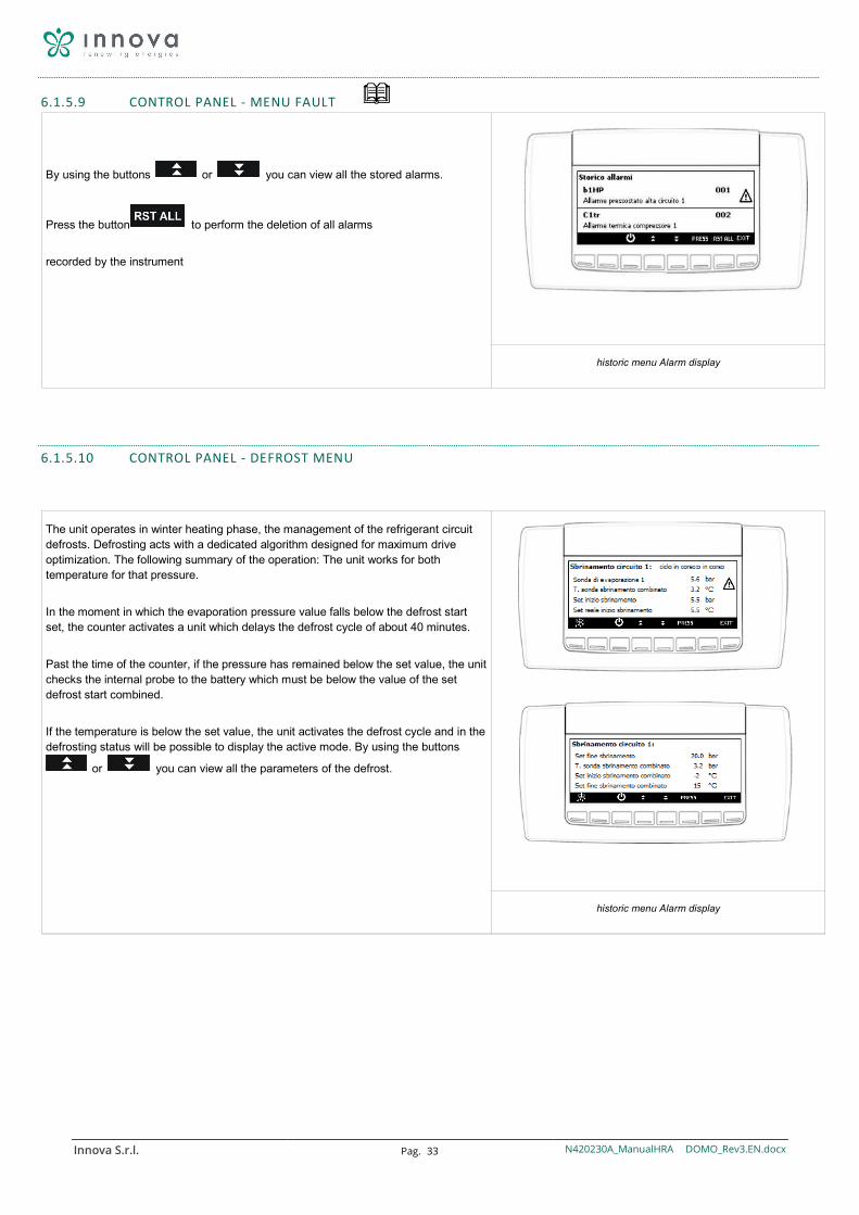
6.1.5.9 CONTROL PANEL - MENU FAULT
By using the buttons or you can view all the stored alarms.
Press the button to perform the deletion of all alarms
recorded by the instrument
historic menu Alarm display
6.1.5.10 CONTROL PANEL - DEFROST MENU
The unit operates in winter heating phase, the management of the refrigerant circuit defrosts. Defrosting acts with a dedicated algorithm designed for maximum drive optimization. The following summary of the operation: The unit works for both temperature for that pressure.
In the moment in which the evaporation pressure value falls below the defrost start set, the counter activates a unit which delays the defrost cycle of about 40 minutes.
Past the time of the counter, if the pressure has remained below the set value, the unit checks the internal probe to the battery which must be below the value of the set defrost start combined.
If the temperature is below the set value, the unit activates the defrost cycle and in the defrosting status will be possible to display the active mode. By using the buttons
or you can view all the parameters of the defrost.
historic menu Alarm display
Innova S.r.l. Pag. 34 N420230A_ManualHRA DOMO_Rev3.EN.docx
6.1.5.11 CONTROL PANEL - MENU STATES INPUT / OUTPUT
By using the buttons or select the measures you want to view,
then press to access.
E 'can view:
Analog inputs - Analog outputs
Digital inputs - Digital outputs
menu display states inputs / outputs
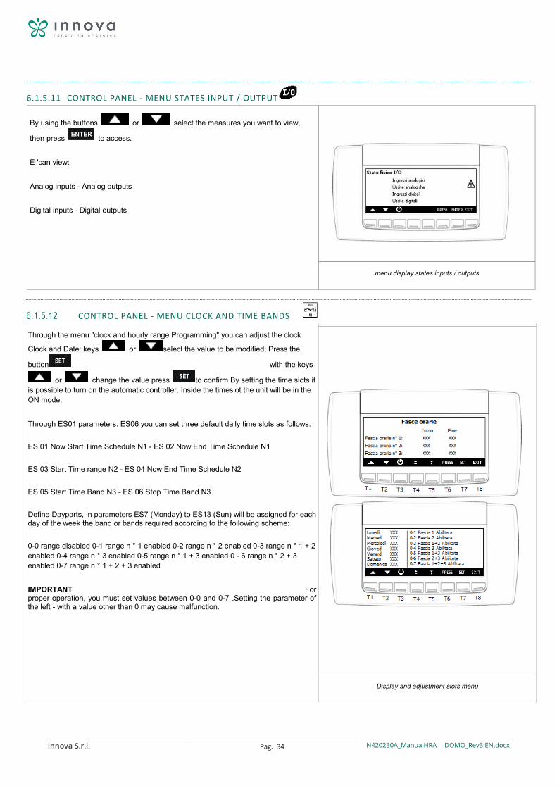
6.1.5.12 CONTROL PANEL - MENU CLOCK AND TIME BANDS
Through the menu "clock and hourly range Programming" you can adjust the clock
Clock and Date: keys or select the value to be modified; Press the
button with the keys
or change the value press to confirm By setting the time slots it is possible to turn on the automatic controller. Inside the timeslot the unit will be in the ON mode;
Through ES01 parameters: ES06 you can set three default daily time slots as follows:
ES 01 Now Start Time Schedule N1 - ES 02 Now End Time Schedule N1
ES 03 Start Time range N2 - ES 04 Now End Time Schedule N2
ES 05 Start Time Band N3 - ES 06 Stop Time Band N3
Define Dayparts, in parameters ES7 (Monday) to ES13 (Sun) will be assigned for each day of the week the band or bands required according to the following scheme:
0-0 range disabled 0-1 range n ° 1 enabled 0-2 range n ° 2 enabled 0-3 range n ° 1 + 2 enabled 0-4 range n ° 3 enabled 0-5 range n ° 1 + 3 enabled 0 - 6 range n ° 2 + 3 enabled 0-7 range n ° 1 + 2 + 3 enabled
IMPORTANT For proper operation, you must set values between 0-0 and 0-7 .Setting the parameter of the left - with a value other than 0 may cause malfunction.
Display and adjustment slots menu
Innova S.r.l. Pag. 35 N420230A_ManualHRA DOMO_Rev3.EN.docx
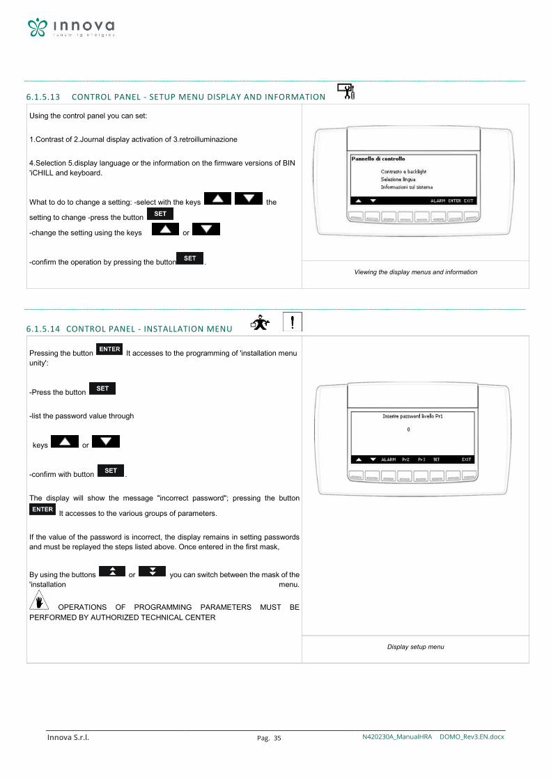
6.1.5.13 CONTROL PANEL - SETUP MENU DISPLAY AND INFORMATION
Using the control panel you can set:
1.Contrast of 2.Journal display activation of 3.retroilluminazione
4.Selection 5.display language or the information on the firmware versions of BIN 'iCHILL and keyboard.
What to do to change a setting: -select with the keys the
setting to change -press the button
-change the setting using the keys or
-confirm the operation by pressing the button .
Viewing the display menus and information
6.1.5.14 CONTROL PANEL - INSTALLATION MENU
Pressing the button It accesses to the programming of 'installation menu unity':
-Press the button
-list the password value through
keys or
-confirm with button .
The display will show the message "incorrect password"; pressing the button
It accesses to the various groups of parameters.
If the value of the password is incorrect, the display remains in setting passwords and must be replayed the steps listed above. Once entered in the first mask,
By using the buttons or you can switch between the mask of the 'installation menu.
OPERATIONS OF PROGRAMMING PARAMETERS MUST BE PERFORMED BY AUTHORIZED TECHNICAL CENTER
Display setup menu
Innova S.r.l. Pag. 36 N420230A_ManualHRA DOMO_Rev3.EN.docx
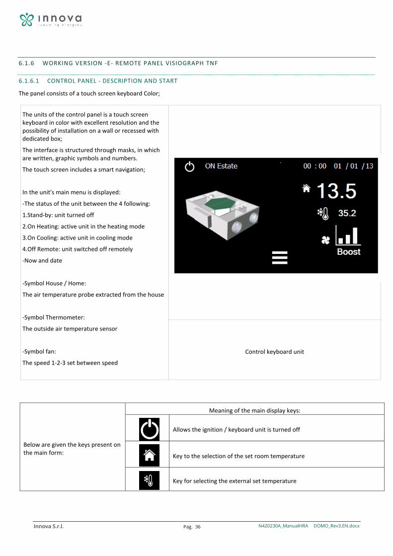
6.1.6 WORKING VERSION -E- REMOTE PANEL VISIOGRAPH TNF
6.1.6.1 CONTROL PANEL - DESCRIPTION AND START
The panel consists of a touch screen keyboard Color;
The units of the control panel is a touch screen keyboard in color with excellent resolution and the possibility of installation on a wall or recessed with dedicated box;
The interface is structured through masks, in which are written, graphic symbols and numbers.
The touch screen includes a smart navigation;
In the unit's main menu is displayed:
-The status of the unit between the 4 following:
1.Stand-by: unit turned off
2.On Heating: active unit in the heating mode
3.On Cooling: active unit in cooling mode
4.Off Remote: unit switched off remotely
-Now and date
-Symbol House / Home:
The air temperature probe extracted from the house
-Symbol Thermometer:
The outside air temperature sensor
-Symbol fan:
The speed 1-2-3 set between speed
Control keyboard unit
Below are given the keys present on the main form:
Meaning of the main display keys:
Allows the ignition / keyboard unit is turned off
Key to the selection of the set room temperature
Key for selecting the external set temperature
Innova S.r.l. Pag. 37 N420230A_ManualHRA DOMO_Rev3.EN.docx
Button for selecting the fan speed / booster function
It lets get into the icon menu for navigation of advanced features and drive menu
Viewing the main mask keys
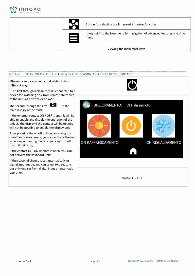
6.1.6.2 TURNING ON THE UNIT POWER OFF 'SEASON AND SELECTION KEYBOARD
-The unit can be enabled and disabled in two different ways.
The first through a clean contact connected to a device for switching on / from remote shutdown of the unit: as a switch or a timer.
The second through the key in the main display of the mask.
If the external contact ON / OFF is open it will be able to enable and disable the operation of the unit via the display if the contact will be opened will not be possible to enable the display unit.
After pressing the on off button, accessing the on-off and season mask, you can activate the unit in cooling or heating mode or you can turn off the unit if it is on;
If the contact OFF ON Remote is open, you can not activate the keyboard unit;
If the seasonal change is set automatically or digital input mode, you can select two seasons but only one set from digital input or automatic operation;
Button ON OFF
Innova S.r.l. Pag. 38 N420230A_ManualHRA DOMO_Rev3.EN.docx
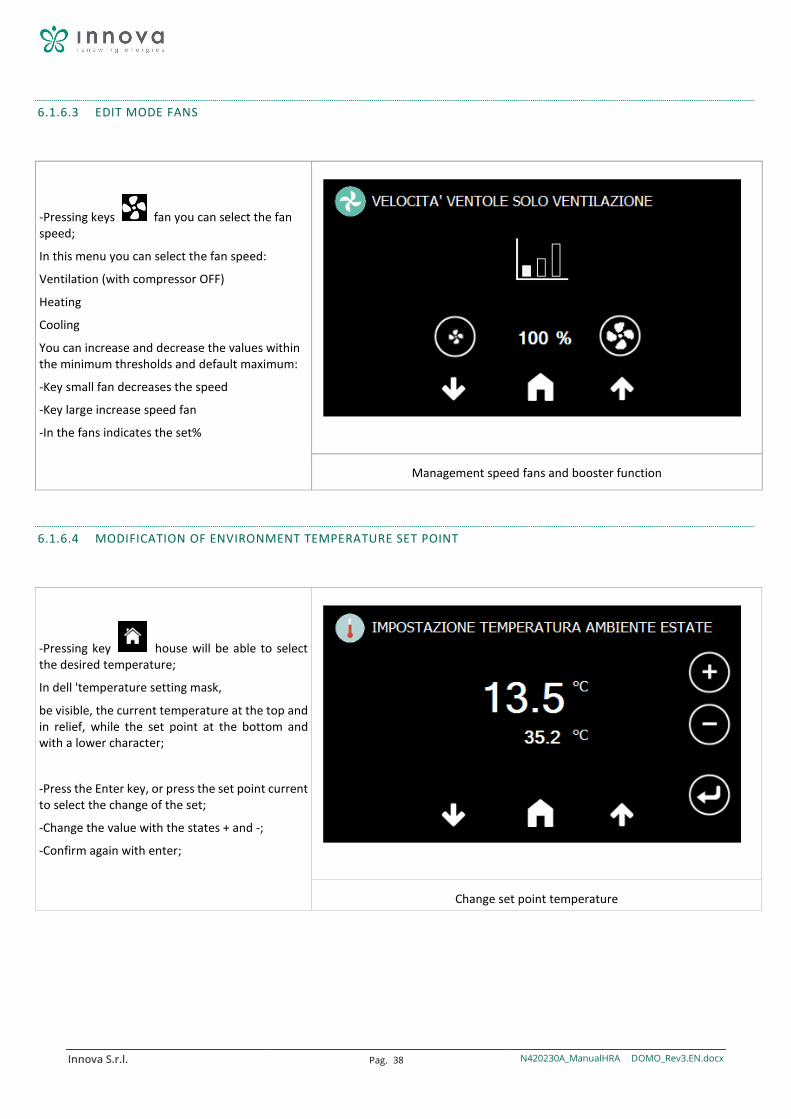
6.1.6.3 EDIT MODE FANS
-Pressing keys fan you can select the fan speed;
In this menu you can select the fan speed:
Ventilation (with compressor OFF)
Heating
Cooling
You can increase and decrease the values within the minimum thresholds and default maximum:
-Key small fan decreases the speed
-Key large increase speed fan
-In the fans indicates the set%
Management speed fans and booster function
6.1.6.4 MODIFICATION OF ENVIRONMENT TEMPERATURE SET POINT
-Pressing key house will be able to select the desired temperature;
In dell 'temperature setting mask,
be visible, the current temperature at the top and in relief, while the set point at the bottom and with a lower character;
-Press the Enter key, or press the set point current to select the change of the set;
-Change the value with the states + and -;
-Confirm again with enter;
Change set point temperature
Innova S.r.l. Pag. 39 N420230A_ManualHRA DOMO_Rev3.EN.docx
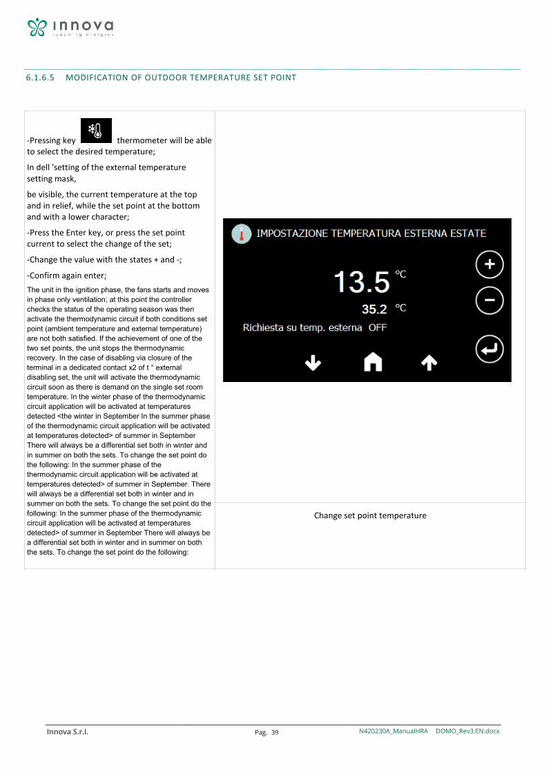
6.1.6.5 MODIFICATION OF OUTDOOR TEMPERATURE SET POINT
-Pressing key thermometer will be able to select the desired temperature;
In dell 'setting of the external temperature setting mask,
be visible, the current temperature at the top and in relief, while the set point at the bottom and with a lower character;
-Press the Enter key, or press the set point current to select the change of the set;
-Change the value with the states + and -;
-Confirm again enter; The unit in the ignition phase, the fans starts and moves in phase only ventilation; at this point the controller checks the status of the operating season was then activate the thermodynamic circuit if both conditions set point (ambient temperature and external temperature) are not both satisfied. If the achievement of one of the two set points, the unit stops the thermodynamic recovery. In the case of disabling via closure of the terminal in a dedicated contact x2 of t ° external disabling set, the unit will activate the thermodynamic circuit soon as there is demand on the single set room temperature. In the winter phase of the thermodynamic circuit application will be activated at temperatures detected <the winter in September In the summer phase of the thermodynamic circuit application will be activated at temperatures detected> of summer in September There will always be a differential set both in winter and in summer on both the sets. To change the set point do the following: In the summer phase of the thermodynamic circuit application will be activated at temperatures detected> of summer in September. There will always be a differential set both in winter and in summer on both the sets. To change the set point do the following: In the summer phase of the thermodynamic circuit application will be activated at temperatures detected> of summer in September There will always be a differential set both in winter and in summer on both the sets. To change the set point do the following:
Change set point temperature
Innova S.r.l. Pag. 40 N420230A_ManualHRA DOMO_Rev3.EN.docx
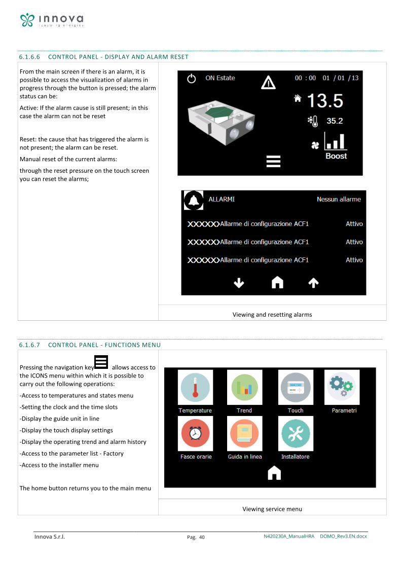
6.1.6.6 CONTROL PANEL - DISPLAY AND ALARM RESET
From the main screen if there is an alarm, it is possible to access the visualization of alarms in progress through the button is pressed; the alarm status can be:
Active: If the alarm cause is still present; in this case the alarm can not be reset
Reset: the cause that has triggered the alarm is not present; the alarm can be reset.
Manual reset of the current alarms:
through the reset pressure on the touch screen you can reset the alarms;
Viewing and resetting alarms
6.1.6.7 CONTROL PANEL - FUNCTIONS MENU
Pressing the navigation key allows access to the ICONS menu within which it is possible to carry out the following operations:
-Access to temperatures and states menu
-Setting the clock and the time slots
-Display the guide unit in line
-Display the touch display settings
-Display the operating trend and alarm history
-Access to the parameter list - Factory
-Access to the installer menu
The home button returns you to the main menu
Viewing service menu
Innova S.r.l. Pag. 41 N420230A_ManualHRA DOMO_Rev3.EN.docx
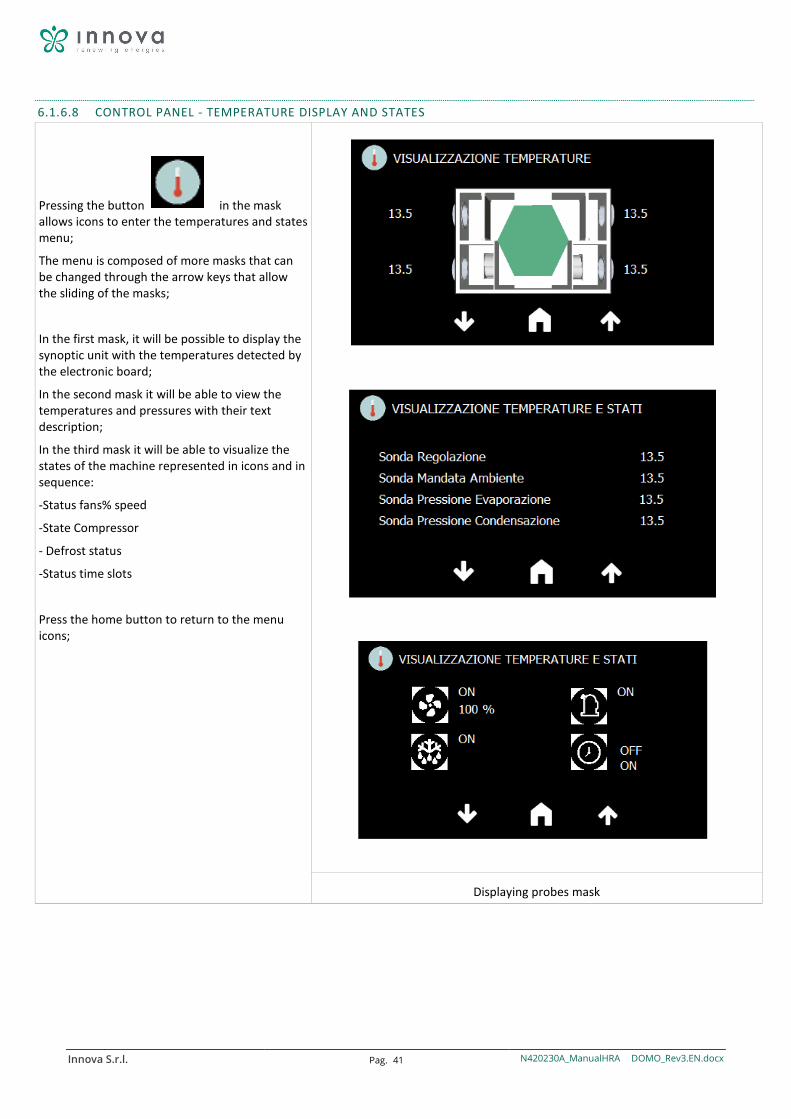
6.1.6.8 CONTROL PANEL - TEMPERATURE DISPLAY AND STATES
Pressing the button in the mask allows icons to enter the temperatures and states menu;
The menu is composed of more masks that can be changed through the arrow keys that allow the sliding of the masks;
In the first mask, it will be possible to display the synoptic unit with the temperatures detected by the electronic board;
In the second mask it will be able to view the temperatures and pressures with their text description;
In the third mask it will be able to visualize the states of the machine represented in icons and in sequence:
-Status fans% speed
-State Compressor
- Defrost status
-Status time slots
Press the home button to return to the menu icons;
Displaying probes mask
Innova S.r.l. Pag. 42 N420230A_ManualHRA DOMO_Rev3.EN.docx
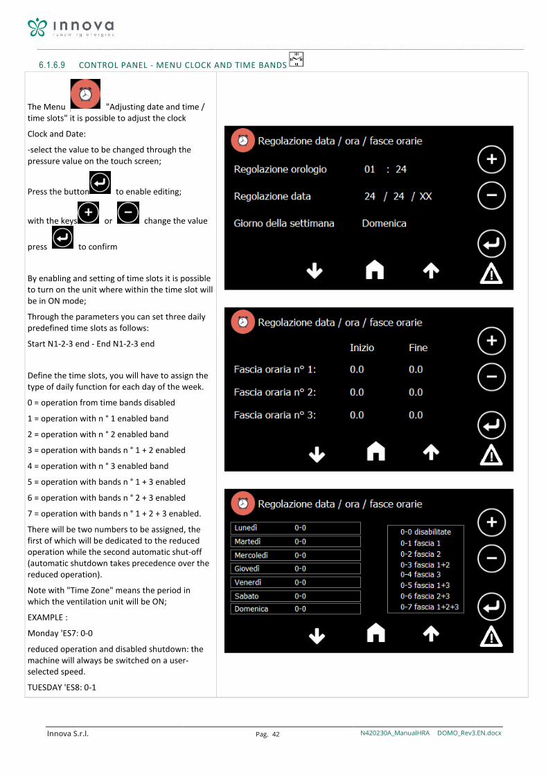
6.1.6.9 CONTROL PANEL - MENU CLOCK AND TIME BANDS
The Menu "Adjusting date and time / time slots" it is possible to adjust the clock
Clock and Date:
-select the value to be changed through the pressure value on the touch screen;
Press the button to enable editing;
with the keys or change the value
press to confirm
By enabling and setting of time slots it is possible to turn on the unit where within the time slot will be in ON mode;
Through the parameters you can set three daily predefined time slots as follows:
Start N1-2-3 end - End N1-2-3 end
Define the time slots, you will have to assign the type of daily function for each day of the week.
0 = operation from time bands disabled
1 = operation with n ° 1 enabled band
2 = operation with n ° 2 enabled band
3 = operation with bands n ° 1 + 2 enabled
4 = operation with n ° 3 enabled band
5 = operation with bands n ° 1 + 3 enabled
6 = operation with bands n ° 2 + 3 enabled
7 = operation with bands n ° 1 + 2 + 3 enabled.
There will be two numbers to be assigned, the first of which will be dedicated to the reduced operation while the second automatic shut-off (automatic shutdown takes precedence over the reduced operation).
Note with "Time Zone" means the period in which the ventilation unit will be ON;
EXAMPLE :
Monday 'ES7: 0-0
reduced operation and disabled shutdown: the machine will always be switched on a user-selected speed.
TUESDAY 'ES8: 0-1
Innova S.r.l. Pag. 43 N420230A_ManualHRA DOMO_Rev3.EN.docx
reduced operation disabled, shutdown function unit with wing n ° 1 enabled: the machine will be switched off while the band 1 and will be turned on during the rest of the day a user-selected speed.
THURSDAY 'ES10 = 3-7
reduced operation with bands n ° 1 + 2 enabled, shutdown function unit with bands n ° 1 + 2 + 3 enabled: the machine will be switched off during the bands 1 2 3 and will be turned on during the rest of the day a user-selected speed.
Viewing and clock adjustment menu
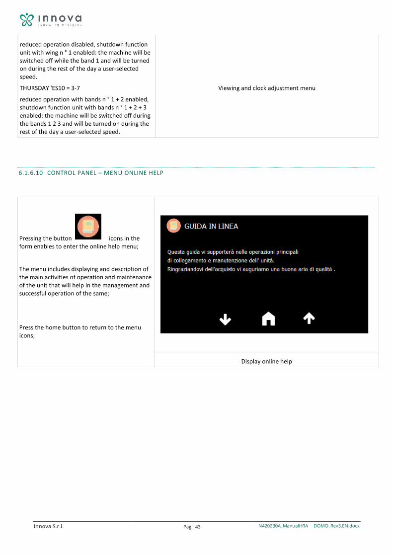
6.1.6.10 CONTROL PANEL – MENU ONLINE HELP
Pressing the button icons in the form enables to enter the online help menu;
The menu includes displaying and description of the main activities of operation and maintenance of the unit that will help in the management and successful operation of the same;
Press the home button to return to the menu icons;
Display online help
Innova S.r.l. Pag. 44 N420230A_ManualHRA DOMO_Rev3.EN.docx
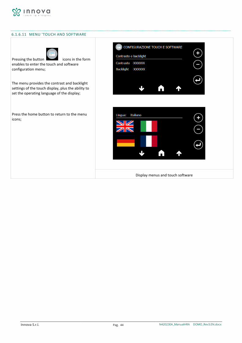
6.1.6.11 MENU 'TOUCH AND SOFTWARE
Pressing the button icons in the form enables to enter the touch and software configuration menu;
The menu provides the contrast and backlight settings of the touch display, plus the ability to set the operating language of the display;
Press the home button to return to the menu icons;
Display menus and touch software
Innova S.r.l. Pag. 45 N420230A_ManualHRA DOMO_Rev3.EN.docx
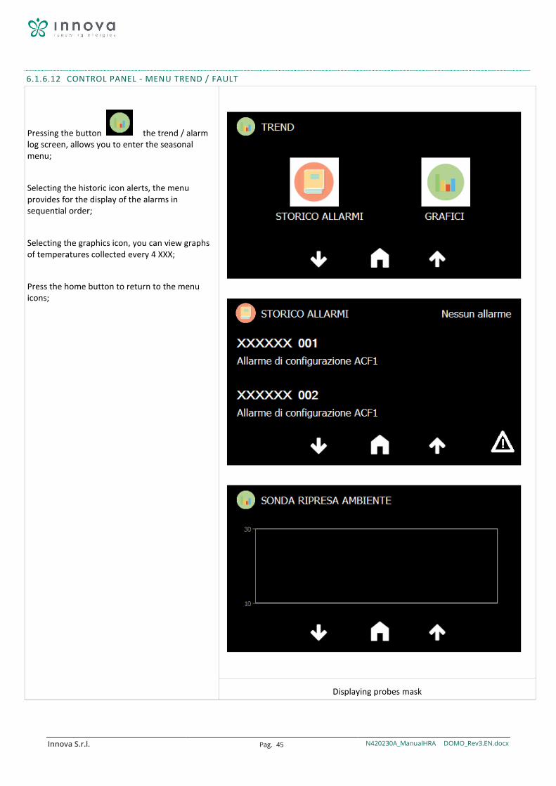
6.1.6.12 CONTROL PANEL - MENU TREND / FAULT
Pressing the button the trend / alarm log screen, allows you to enter the seasonal menu;
Selecting the historic icon alerts, the menu provides for the display of the alarms in sequential order;
Selecting the graphics icon, you can view graphs of temperatures collected every 4 XXX;
Press the home button to return to the menu icons;
Displaying probes mask

Innova S.r.l. Pag. 46 N420230A_ManualHRA DOMO_Rev3.EN.docx
6.1.6.13 CONTROL PANEL - MENU INSTALLER
keypress It allows you to enter the installer menu;
The installer menu entry involves the insertion of a password:
-the installer password
-press touch on the input value password
- with the keys or change the value
- to press to confirm
The display will show the message "incorrect
password"; pressing the button allow access to installer menu;
If the value of the password is incorrect, the display remains in setting passwords and must be replayed the steps listed above.
THE PROGRAMMING OPERATIONS
THE MENU PARAMETERS 'INSTALLER MAY MODIFY SOME FEATURES AND LOGIC UNIT'; PAY ATTENTION TO CHANGES;
THE MANUFACTURER WILL NOT MAKE RESPONSIBLE FOR ANY CHANGES THAT DO NOT GUARANTEE THE PERFORMANCE FROM TECHNICAL DECLARED ';
Installer menu display
Innova S.r.l. Pag. 47 N420230A_ManualHRA DOMO_Rev3.EN.docx
7 MAINTENANCE
To always ensure the proper and optimal operation of the unit, it is necessary to periodically perform all maintenance interventions.
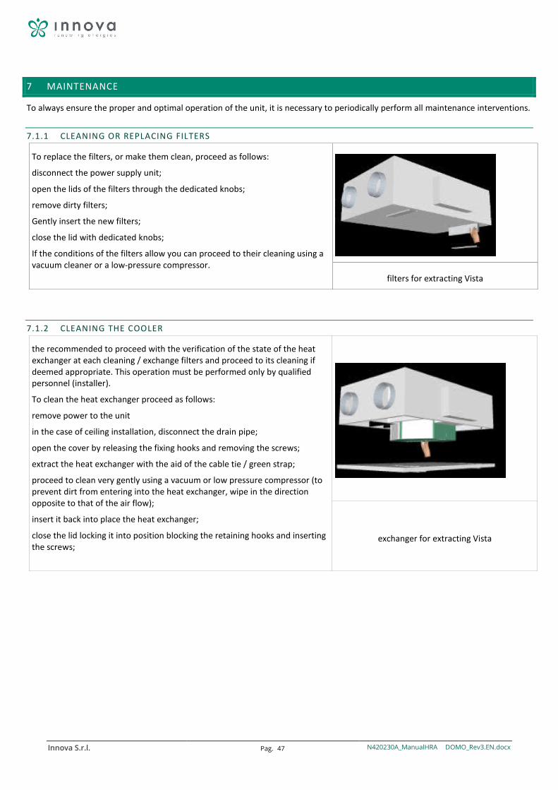
7.1.1 CLEANING OR REPLACING FILTERS
To replace the filters, or make them clean, proceed as follows:
disconnect the power supply unit;
open the lids of the filters through the dedicated knobs;
remove dirty filters;
Gently insert the new filters;
close the lid with dedicated knobs;
If the conditions of the filters allow you can proceed to their cleaning using a vacuum cleaner or a low-pressure compressor.
filters for extracting Vista
7.1.2 CLEANING THE COOLER
the recommended to proceed with the verification of the state of the heat exchanger at each cleaning / exchange filters and proceed to its cleaning if deemed appropriate. This operation must be performed only by qualified personnel (installer).
To clean the heat exchanger proceed as follows:
remove power to the unit
in the case of ceiling installation, disconnect the drain pipe;
open the cover by releasing the fixing hooks and removing the screws;
extract the heat exchanger with the aid of the cable tie / green strap;
proceed to clean very gently using a vacuum or low pressure compressor (to prevent dirt from entering into the heat exchanger, wipe in the direction opposite to that of the air flow);
insert it back into place the heat exchanger;
close the lid locking it into position blocking the retaining hooks and inserting the screws;
exchanger for extracting Vista
Innova S.r.l. Pag. 48 N420230A_ManualHRA DOMO_Rev3.EN.docx
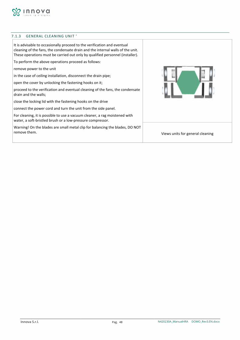
7.1.3 GENERAL CLEANING UNIT '
It is advisable to occasionally proceed to the verification and eventual cleaning of the fans, the condensate drain and the internal walls of the unit. These operations must be carried out only by qualified personnel (installer).
To perform the above operations proceed as follows:
remove power to the unit
in the case of ceiling installation, disconnect the drain pipe;
open the cover by unlocking the fastening hooks on it;
proceed to the verification and eventual cleaning of the fans, the condensate drain and the walls;
close the locking lid with the fastening hooks on the drive
connect the power cord and turn the unit from the side panel.
For cleaning, it is possible to use a vacuum cleaner, a rag moistened with water, a soft-bristled brush or a low-pressure compressor.
Warning! On the blades are small metal clip for balancing the blades, DO NOT remove them.
Views units for general cleaning
Innova S.r.l. Pag. 49 N420230A_ManualHRA DOMO_Rev3.EN.docx
8 ALARMS
8.1.1 GENERALITY'
In case of problems or failures, take note of any error code appeared on the display of the electronic control unit or the remote control, make a note of the model and the serial number of unit you have (present on the nameplate attached on the side of 'units) and contact your installer.
8.1.2 PROBLEMS WITHOUT ERROR INDICATION ON DISPLAY
PROBLEM CAUSE REMEDIES
The fans are not active
-Power supply is not inserted
-Not works of the fan speed control device
incorrect electrical -Links
-Ventilatori in thermal protection
-Make the power supply on the fan
-Verify of the fan speed control device
-Check that the fan is not
overheated and thermal protection
Air flow rate or pressure insufficient helpful
-Filters clogged
-Speed Insufficient rotation
-Tubazioni or clogged exchanger
-Clean the filters
-Increase the speed of rotation
-Clean pipes or heat exchanger
Insufficient exchanger Yield -Alette exchanger clogged -Clean the surfaces of the exchanger
Excessive vibration and noise
-Installation incorrect unit
-Installation incorrect piping
-Squilibrio of fan impeller
-Check brackets and hardware unit
-Verify brackets and hardware piping
-Verify status of fan impellers
Water leakage from the unit
-Drain clogged condensation
-Sifone not properly installed
-Clean the condensate drain
-Check the correct installation of the siphon
difficult start -Voltage of too low
-Pair insufficient motor
-Make sure that the supply voltage is not below the 10% of the rated voltage
-Food the unit with partially closed shutters so as to reduce the engine torque. In case of departure correct, replace the motor with a plus.
Innova S.r.l. Pag. 50 N420230A_ManualHRA DOMO_Rev3.EN.docx
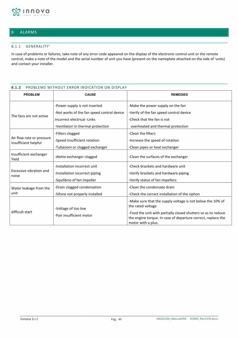
8.1.3 TABLE ALARMS REPORTED TO DISPLAY
Below is a table of reported unit malfunctions, in electronic versions, from the display on the machine or from remote controls.
B1HP Alarm high pressure switch -Excessive refrigerant
charge -Low flow side condensation -High air temperature in the condensation side output
-Make the pressure of the refrigerant circuit -Check the air temperature on the condensation side (winter-user estate- dissipation) -Verify the air flow on the side of condensation (winter-user estate- dissipation) -Verify the operating limits
B1hP High pressure alarm from pressure transducer
-Excessive refrigerant charge -Low air flow condensing side -High temperature of the air in the condensation side output
-Make the pressure and the refrigerant circuit charge -Check the air temperature on the condensation side (winter-user estate- dissipation) -Verify the air flow on the side of condensation (winter-user estate- dissipation) -Verify the limits of operation
B1lP Low pressure alarm from pressure transducer
-Low refrigerant charge -Low air flow evaporation side -Low air temperature at the outlet side refrigerant evaporation -Filter clogged -Block not recognized electronic expansion valve
-Make the pressure and charging of the refrigerant circuit -Verify air temperatures on the evaporation side (winter-dissipation estate- catchment) -Verify the air flow on the side of condensation (winter-dissipation estate- catchment) -Verify if there is temperature difference between the filter inlet and the outlet refrigerant -Verify if the command of the electronic valve driver has an alarm condition
B1LP Alarm electronic thermostatic valve
-Faulty driver operation or electronic valve
-Make the connections and the connectors of the electronic valve and its temperature and pressure probes
ARTC Alarm clock -Wrong internal clock of the instrument time and date set not real
-Try to change the time and date in the menu '
Art1 Remote Terminal alarm TAL
-Wrong operation or non-connection of the remote terminal TAL
-Try check the connection
Avis visiograph terminal Alarm -Wrong operation or non-connection of the remote terminal VISIOGRAPH
-Try check the connection
Nol communication alarm -No communication with the terminal
-Check if respected connections
AP 1/10
temperature probe Alarm -No reading or reading probe incorrect value of ntc temperature
-Make the probe connections -Make sure that the probe resistance omnica is within the limit values
AP 3/4 Pressure probe alarm -No reading or reading probe incorrect value pressure
-Check the transducer connections -Make sure that the current / voltage transducer is within limits
Nol remote terminal Alarm -Lack of communication with the controller (fault in the + pole of the keyboard)
-Check that links the terminal Remote are correct
ARTC Alarm clock -Clock to adjust -Setting the time and the current date ARTF Alarm clock -Clock failure -Replace the unit control board EEE EPROM Alarm -The instrument can not
store alerts or state machine; the causes may be a failure, or of disorders that have caused the "fouling" of the registration memory
-Replace the unit control board
Innova S.r.l. Pag. 51 N420230A_ManualHRA DOMO_Rev3.EN.docx
9 NOTES AND INFORMATION SERVICE
NOTE
-------------------------------------------------- -------------------------------------------------- -------------------------------------------------- -------------------------------------------------- -------------------------------------------------- -------------------------------------------------- ----------------------
-------------------------------------------------- -------------------------------------------------- -------------------------------------------------- -------------------------------------------------- -------------------------------------------------- -------------------------------------------------- ----------------------
-------------------------------------------------- -------------------------------------------------- -------------------------------------------------- -------------------------------------------------- -------------------------------------------------- -------------------------------------------------- ----------------------
-------------------------------------------------- -------------------------------------------------- -------------------------------------------------- -------------------------------------------------- -------------------------------------------------- -------------------------------------------------- ----------------------
-------------------------------------------------- -------------------------------------------------- -------------------------------------------------- -------------------------------------------------- -------------------------------------------------- -------------------------------------------------- ----------------------
-------------------------------------------------- -------------------------------------------------- -------------------------------------------------- -------------------------------------------------- -------------------------------------------------- -------------------------------------------------- ----------------------
-------------------------------------------------- -------------------------------------------------- -------------------------------------------------- -------------------------------------------------- -------------------------------------------------- -------------------------------------------------- ----------------------
-------------------------------------------------- -------------------------------------------------- -------------------------------------------------- -------------------------------------------------- -------------------------------------------------- -------------------------------------------------- ----------------------
-------------------------------------------------- -------------------------------------------------- -------------------------------------------------- -------------------------------------------------- -------------------------------------------------- -------------------------------------------------- ----------------------
-------------------------------------------------- -------------------------------------------------- -------------------------------------------------- -------------------------------------------------- -------------------------------------------------- -------------------------------------------------- ----------------------
-------------------------------------------------- -------------------------------------------------- -------------------------------------------------- -------------------------------------------------- -------------------------------------------------- -------------------------------------------------- ----------------------
-------------------------------------------------- -------------------------------------------------- -------------------------------------------------- -------------------------------------------------- -------------------------------------------------- -------------------------------------------------- ----------------------
-------------------------------------------------- -------------------------------------------------- -------------------------------------------------- -------------------------------------------------- -------------------------------------------------- -------------------------------------------------- ----------------------
-------------------------------------------------- -------------------------------------------------- -------------------------------------------------- -------------------------------------------------- -------------------------------------------------- -------------------------------------------------- ----------------------
-------------------------------------------------- -------------------------------------------------- -------------------------------------------------- -------------------------------------------------- -------------------------------------------------- -------------------------------------------------- ----------------------
-------------------------------------------------- -------------------------------------------------- -------------------------------------------------- -------------------------------------------------- -------------------------------------------------- -------------------------------------------------- ----------------------
-------------------------------------------------- -------------------------------------------------- -------------------------------------------------- -------------------------------------------------- -------------------------------------------------- -------------------------------------------------- ----------------------
-------------------------------------------------- -------------------------------------------------- -------------------------------------------------- -------------------------------------------------- -------------------------------------------------- -------------------------------------------------- ----------------------
Innova S.r.l. Pag. 52 N420230A_ManualHRA DOMO_Rev3.EN.docx
-------------------------------------------------- -------------------------------------------------- -------------------------------------------------- -------------------------------------------------- -------------------------------------------------- -------------------------------------------------- ----------------------
-------------------------------------------------- -------------------------------------------------- -------------------------------------------------- -------------------------------------------------- -------------------------------------------------- -------------------------------------------------- ----------------------
-------------------------------------------------- -------------------------------------------------- -------------------------------------------------- -------------------------------------------------- -------------------------------------------------- -------------------------------------------------- ----------------------
-------------------------------------------------- -------------------------------------------------- -------------------------------------------------- -------------------------------------------------- -------------------------------------------------- -------------------------------------------------- ----------------------
-------------------------------------------------- -------------------------------------------------- -------------------------------------------------- -------------------------------------------------- -------------------------------------------------- -------------------------------------------------- ----------------------
-------------------------------------------------- -------------------------------------------------- -------------------------------------------------- -------------------------------------------------- -------------------------------------------------- -------------------------------------------------- ----------------------
-------------------------------------------------- -------------------------------------------------- -------------------------------------------------- -------------------------------------------------- -------------------------------------------------- -------------------------------------------------- ----------------------
-------------------------------------------------- -------------------------------------------------- -------------------------------------------------- -------------------------------------------------- -------------------------------------------------- -------------------------------------------------- ----------------------
1 2018 Rev.03
Technical Assistance Center
The data contained herein may be modified by the manufacturer without notice.