SERVODRIVE - · PDF file1 Modifiche al Manuale e al Drive DGM 25/10/2006 DGM02 REV 2_04 Laux...
90
SERVODRIVE - DGM
-
Upload
dinhkhuong -
Category
Documents
-
view
214 -
download
1
Transcript of SERVODRIVE - · PDF file1 Modifiche al Manuale e al Drive DGM 25/10/2006 DGM02 REV 2_04 Laux...

SERVODRIVE - DGM

1
Modifiche al Manuale e al Drive DGM
25/10/2006 DGM02 REV 2_04 Laux
26/10/2006 DGM02 REV 2_05 Posizionatore: azzeramento origine; Rampa normale ccontinua (RNC)
06/04/2007 DGM02 REV 2_07 Aggiunto colonna taglie; Modificato secondi in minuti su i2t motore
23/01/2008 DGM03 REV 3_00 Adeguamento alla versione 3.xx del firmware dei DGM.Aggiunto parametri di scelta del tipo di
riferimento; Aggiunto possibilità di ripristino automatico I2t; Aggiunta possibilità di disabilitazione allarme F11(mancanza +24); Aggiunto parametro P5003 (tempo anticipo quota raggiunta).
13/11/2008 DGM03 REV 3_01 Aggiunto parametro P4104
25/01/2010 DGM03 REV 3_02 Aggiunto nota su allarme F15; Aggiunto taglia 75A
DGM03 REV 3_03
11/04/2011 DGM03 REV 3_04 Aggiunta spiegazione parametri C000,P000,A000,S4007-8,P5003,S5002,S5003,S7202,S7203,S7300.
Adeguamento spiegazione parametri P4101,A3002.Aggiunto applicativo camma elettronica:E. Aggiunte
spiegazioni allarmi SPD (Secure Power Disable). Aggiunto connettore J7
21/06/2011 DGM03 Rev 6_00 Sistemato conn.J5
19/04/2012 DGM06 REV 6_01 Corretto errore “pin 3 at gnd” con “pin2 at gnd” pag.62 e 72.
04/09/2012 DGM06 REV 6_02 Corretto pag.44 spostato di una riga i commenti dei parametri U.2400 fino a U.3006
27/02/2014 DGM06 REV 6_03 • The voltage Laux for DGM240 is essential and you do not need the isolation transformer. (P.
9,10,18)
• On DGM with Hardware Version V = 1, the pin 14 of connector J3 is no longer a common 0B; it
becomes RTS signal and is used for the firmware update. (P.24)
• Added function of CW CCW frequency input mode in electronic gear box mode
• Added torque limit input function on out2 parameter S.5004 ((firmware version 6.15)
• Added limit torque 2, Parameter S.5005 ((firmware version 6.16)
• Removed parameter U1103, and replace it with U.5000 (firmware version 6.23)
• Added resolver reverse parameter S.3005 (firmware version 6.26)
• Increased up to +-3200.0 the offset values of the analog speed reference (firmware version 6.38)
• Moved parameter from A.4003 to A.3003 (firmware version 6.39)
• Added description J6 connector
• Added the digital functions of the aux analog inputs
• Added function torque limit 2 by input I9
• Added parameters H.1003 (firmware version 6.32)
• Added parameters H.1004 (firmware version 6.39)
11/06/2014 DGM06 REV 6_04 • Removed parameter H.1004 (Firmware Version 6:39)
• Added description of function digital inputs
• Correct p.57 input for JOG

2
Doc.N. ATIVA
Rev.N. 1
Data 28/10/2014

3
WARNINGS
Read carefully this manual before the use of the converter.
Take care of this handbook and keep it at hand for later reference.
Please make sure that this handbook is delivered to the final customer and user.
ATTENTION
This drive contains high voltage circuits that may be fatal to humans. Electric shock may accur if the following points are not observed: Maintenance must be performed by qualified technicals. Before any maintenance, power supply must be disconnected. The capacitors inside the drive can keep a charge for about 8 minutes after turning off
the power. So wait at least 8 minutes, after turning off the power, before any maintenance operation inside the drive.Teh high voltage in teh capacitors is also present between the terminals DC- and DC+
Always ground the drive case. The grounding method must comply with the laws of the
Country where the inverter is being installed. The machine operator must receive an adapt preparation.
The drive may be destroyed if the following points are not observed:
Observe the drive specifiations and the warnings contained in this manual. Always provide an adequate ventilation and keep clean the drive Avoid water or other liquid penetration inside the drive. Connect adequate cable to the imput/output terminals The drive may be source of radio-frequency noise if unprovided of the adequate mains filter.
4
Precaution for safety Here are described the rules to follow in several stage of manipulation of the drive to the aim to avoid damages to persons or things because of a wrong use of the drive. The safety precautions are ranked as DANGER and ATTENTION in this instruction manual:
Note that some items described as "ATTENTION" may lead to major results depending on the situations. Therefore it is important to carefully follow the instruction indicated.
1.Transportation and installation
DANGER
• Not overlap too many pieces one on the other. Below pieces could be damaged.
• Not transport by hand more than a drive according to the drive weight. Failure to observe this could lead to injuries.
• Install the drive on not-combustible stuff (metal) and far away from inflammable products. Failure to observe this could lead to fires.
• Install the drive in a place that can withstand the weight of the product and follow the instruction manual.
It exists the risk of injury owing to the fall of the drive.
• Not obstruct the entry and the escape of the air and not introduce stranger object. Fire danger exists.
• Observe the installation conditions described in the present manual in order not to commit errors.
ATTENTION
• Always turn the device’s input off before starting wiring. Failure to observe this could lead to fires or electrical shocks.
• Carry out the earth connections according to the standards of the country where the drive is installed.
Failure to observe this could lead to fires and electrical shocks.
• Qualified electrical staff must execute the installation. Failure to observe this could lead to fires and electrical shocks.
• Always fix the drive before executing the wiring. Failure to observe this could lead to injuries and electrical shocks.
• Install a protection circuit (fuses or magnetic switch) on the drive supply. Failure to observe this could lead to fires.
DANGER When a dangerous situation may accur for an incorrect use of the drive and this could cause fatal or a serious injury.
ATTENTION When a dangerous situation may accur for an incorrect use of the drive and this could cause a medium or minor injury, or physical damage to things.
5
ATTENTION
• Do not connect any source of three-phase power supply on the terminals U , V, W . Failure to observe this could lead to fires and to electrical shocks.
• Ensure that the drive voltage and the supply frequency of the drive correspond to the voltage and to the frequency of the line.
Failure to observe this could lead to fires and injury.
• Do not connect directly any resistor between the DC clamps of the drive. Failure to observe this could lead to fires.
• Fix the screw of the clamps with an adapted driving torque. Failure to observe this could lead to fires.
• Correct connect the output side (U,V,W). Failure to do so could cause the motor to rotate in reverse and the machine to be damage.
2.Start up
DANGER
• Never supply the drive without the cover and never remove the cover while supply is on. It exists danger of electrical shocks.
• Do not manipulate the drive with wet hands. Failure to observe this could lead to electrical shocks • Do not touch the terminals of the drive while the power is on. Failure to observe this could lead to electrical shocks
• Never touch the possible external braking resistor. Failure to observe this could lead to electrical shocks
• Keep a safety distance from the motor and the machine when the power is on and never touch the rotary parts of the motor when it is in function.
It exists the risk of injury.
• When reset the alarms make sure that the signal of running is enabled in order to avoid unexpected start of the motor. Fix up a separate emergency stop device.
It exists the risk of injury.
ATTENTION
• Never touch the drive, the motor and the possible external braking resistor as they can overtake high temperatures.
Failure to observe this could lead to electrical shocks and burns.
• Do not block the ventilation lits of the drive. Failure to observe this could lead to burns.
• Make sure of the functionality of the motor as single unit before connecting it mechanically to the machine and verify that the max speed of the motor are accepted from the machine.
It exists the danger to hurt and to damage the machine.
6
3.Maintenance, inspection and part replacement.
DANGER
• Always wait at least 8 minutes after turning off the input power before starting inspections. Make sure that the display has been erased and that the voltage between terminals DC+ and DC- is less than 15V.
Failure to observe this could lead to electrical shock.
• The maintenance, the inspection and part replacement must be done by a designated person. (Remove all the metal accessories like watches, bracelets etc before beginning the job.)
Failure to observe this could lead to electrical shocks and injuries.
• Always turn the power off before inspecting the motor or machine. A potential is applied on the motor terminal even when the motor is stopped.
Failure to observe this could lead to electrical shock.
ATTENTION
• Never modify the product. Failure to observe this could lead to electrical shock and injury.
• Vacuum the drive with a vacuum cleaner to clean it. Do not use organic solvents. Failure to observe this could lead to burns or damage.
• For your safe it is very important that any software update have to be done by our company.
• When you have to throw away the drive dispose of this product as industrial waste.

7
INDEX
1 DELIVERY INSPECTION AND STORAGE pag.9
1.1 Delivery inspection and storage
1.2 Label details.
2 DESCRIPTION
2.1 Description pag.10
2.2 Models
3 TECHNICAL INFORMATIONS pag.11
3.1 Electrical features pag.11
3.2 Technical features pag.11
3.3 Front view Pag.12
4 MECHANICAL INSTALLATION AND DIMENSIONS pag.15
4.1 Installation Environment
4.2 Dimensions
5 WIRING HARNESS AND DESCRIPTION OF CONNECTIONS pag.18
5.1 Connector or power terminal board J1 and J2 pag.18
5.1.1 Description of the motor power connector J1 pag.19
5.2 Power supply connector J2 pag.19
5.2.1 Description of the DGM power supply connector J2 pag.21
5.2.2 Description of the connector Safe Torque Off (STO) J6 pag.21
5.3 Resolver connector J4 pag.22
5.4 Simulated encoder connection on J5 connector pag.23
5.4.1 Wiring diagram of RS485 on J3 connector pag.24
5.4.2 Wiring diagram for CANOPEN on J3 connector pag.24
5.4.3 Wiring diagram of RS232 pag.25
5.5 Connection for frequency speed reference on connector J5 pag.24
5.6 J5 connector Inputs pag.26
5.7 J5 connector Outputs pag.27
5.8 J5 Description pag.29
6 OPERATOR PANEL pag.31
6.1 Keyboard description
7 PARAMETERS pag.35
7.1 General diagrams parameters pag.35
7.2 Explanation of the parameters pag.45
7.2.1 Monitor Data pag.45

8
7.2.2 Data Motor pag.46
7.2.3 Type of control pag.47
7.2.4 Speed control pag.48
7.2.5 Torque control pag.55
7.2.6 Position control pag.56
7.2.7 Electronic gearbox (Electric axes) pag.63
7.2.8 Electronic CAM pag.66
7.2.9 Analog Outputs pag.78
7.2.10 Digital Inputs pag.78
7.2.11 Advanced setup pag.79
7.2.12 Reserved parameters area pag.84
8 START UP AND ADJUSTMENT pag.86
8.1 Preliminary controls
8.2 Automatic resolver phasing
9 DIAGNOSTIC pag.87
9.1 List of the alarms stored
10 ELECTROMAGNETIC COMPLIANCE EMC pag.89
9
1. DELIVERY INSPECTION AND STORAGE
1.1 Delivery inspection and storage
1. Remove drive from the packaging and check details on the label that confirm the drive correspond to the one ordered. The rating nameplate is on the left side of the unit.
2. Make sure that the product has not been damaged 3. If the drive is not to be used for a while after purchasing, it has to be stored, possibly with its shipment
covering, in a place with no humidity, absence of vibrations and far from water sprays. 4. Always inspect the inverter before using after a long period storage.

10
2. Description
2.1 Description
The DGM series drives allow controlling Brushless servomotors equipped with resolver for the feedback of the position and the speed.It’s requested a 220V single-phase power supply to feed the logic command board and a threephase or single phase voltage supply to feed the DC power bus. The feeding in alternated current is rectified and levelled in order to supply a DC voltage to DC bus that feeds an IGBT power stage. An internal switching feeder generates all the auxiliary insulated voltages used to supply the electronic circuits. A 32 bit microprocessor, processing different signals, generates the commands to drive the final stage to obtain, using a technique of modulation of the impulse duration (PWM), a sinusoidal alternated current to drive the motor. All the functions and settings are obtained using a data entry keyboard composed by a light red 5 digits display and 4 push buttons. All settings are memorized in an Eeprom. A display moreover allows the possible alarms happened, allowing a fast diagnostic of the fault. All settings can be settled using a Modbus protocol via RS485. A software interface called ACCORD is available to download in our website ( www.ativa-automacao.com.br
This software allows to set up,save and monitoring the DGM datas.
2.2 Models The power available is covered by 4 sizes for model type 240 and 8 types for model type 460. For updated information on our range please visit our web site: www.ativa-automacao.com.br
Output current Input voltage
Rated Max Minim Max Model type
Arms Arms V rms Vrms
Taglia
DGM240 1,5/3 1,5 2,6 150 260 T0
DGM240 3/6 3 6 150
260 T0
DGM240 4/8 4 8 150
260 T1
DGM240 10/20 10 20 150
260 T2
DGM460 1,3/2,6 1,3 2,6 300
480 T0
DGM460 2,5/5 2,5 5 300 480 T1
DGM460 6/12 6 12 300
480 T2
DGM460 10/20 10 20 300
480 T3
DGM460 20/40 20 40 300
480 T3
DGM460 35/70 35 70 300
480 T4
DGM460 45/90 45 90 300
480 T4
DGM460 75/150 75 150 300 480 T5
).
11
3. Technical Information
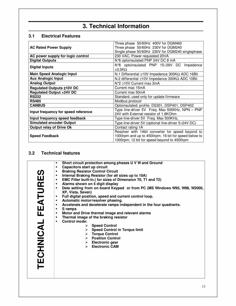
3.1 Electrical Features
AC Rated Power Supply Three phase 50/60Hz 400V for DGM460 Three phase 50/60Hz 230V for DGM240 Single phase 50/60Hz 230V for DGM240 singlephase
AC power supply for logic control 230 VAC. Power requested 20VA Digital Outputs N°6 optoinsulated PNP 24V DC 8 mA
Digital Inputs N°8 optoinsulated PNP 15÷29V DC Impedence
≅3,5KΩ Main Speed Analogic Input N.1 Differential ±10V Impedence 300KΩ ADC 16Bit Aux Analogic Input N.2 differential ±10V Impedance 300KΩ ADC 10Bit Analog Output N°2 ±10V Current max 3mA
Regulated Outputs ±±±±10V DC Current max 15mA
Regulated Output +24V DC Current max 50mA RS232 Standard, used only for update firmware RS485 Modbus protocol CANBUS Optoinsulated; profile: DS301, DSP401, DSP402
Input frequency for speed reference Type line-driver 5V Freq. Max 500KHz, NPN – PNP 24V with External resistor of 1.8KOhm
Input frequency speed feedback Type line-driver 5V Freq. Max 500KHz,
Simulated encoder Output Type line-driver 5V (optional line-driver 5÷24V DC) Output relay of Drive Ok Contact rating 1A
Speed Feedback Resolver with 14bit converter for speed beyond to 1000rpm and up to 4500rpm; 16 bit for speed below to 1000rpm; 12 bit for speed beyond to 4500rpm
3.2 Technical features
TE
CH
NIC
AL
FE
AT
UR
ES
Short circuit protection among phases U V W and Ground Capacitors start up circuit Braking Resistor Control Circuit Internal Braking Resistor (for all sizes up to 10A) EMC Filter built-in.( for sizes of Dimension T0, T1 and T2) Alarms shown on 5 digit display Data setting from on board Keypad or from PC (MS Windows W95, W98, W2000,
XP, Vista, Seven) Full digital position, speed and current control loop. Automatic motor/resolver phasing. Accelerate and decelerate ramps independent in the four quadrants. S ramps Motor and Drive thermal image and relevant alarms Thermal image of the braking resistor Control mode:
Speed Control Speed Control in Torque limit Torque Control Position Control Electronic gear Electronic CAM

12
3.3 FRONT VIEW
L3
L1
L2
+DC BUS
INT B.R.
EXT B.R.
J2J5
U
L AUX 1
L AUX 2
-DC BUS
W
VJ1
J4
J3
ESC ENTER
DGM
-DC BUS
MOTOR POWER
CONNECTOR
V
W
U
J1
L2
L1
J2
L3
EXT B.R.
J5
INT B.R.
+DC BUS
J4
L AUX 2
L AUX 1
J3
ENTERESC
DGM 460
Figura 1 : SIZE T0,T1,T2
Figura 2 : SIZE T3
ATIVA
ATIVAATIVA

13
Figura 1 DGM SIZE T4
J5
DGM 460
J4
J3
ESC ENTER
ATIVA
14
J5
J4
ESC
J3
ENTER
DGM 460
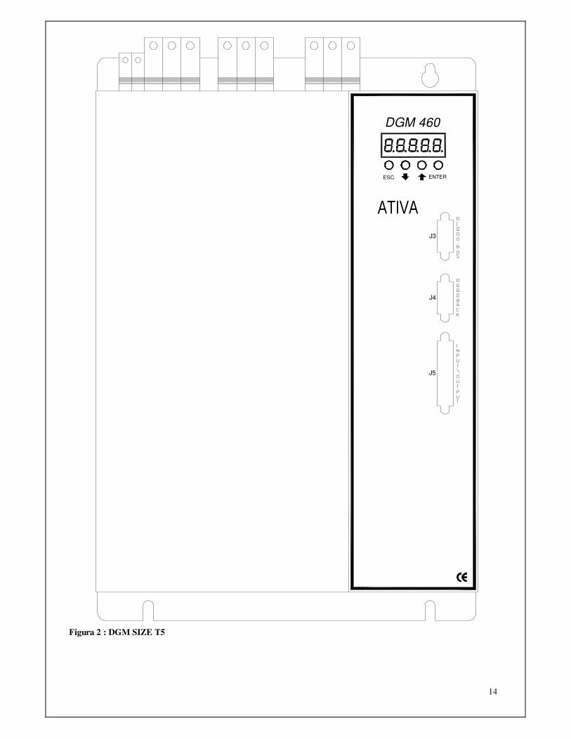
Figura 2 : DGM SIZE T5
ATIVA

15
4. Mechanical installation and dimensions
4.1 Installation environment
Please follow the following instruction during the installation: 1) Install the drive in a vertical and perpendicular position regarding the floor 2) Insure yourself that the environment temperature is comprised between 0 and 45° Celsius 3) Avoid the following conditions:
• Direct exposure to the solar light
• Assemble in places with presence of powders, soil, particles of iron. • Assemble in places with corrosive gas, explosive gas or high grade of humidity.
• Assemble in proximity of machines that generate vibrations.
• Assemble in proximity or on inflammable matter (as wood) or not resistant to the heat. 4) Insure yourself that the driver will be assembled in a position that guarantee a correct ventilation
as you can see in the figure below:
L3
L1
L2
+DC BUS
INT B.R.
EXT B.R.
J2J5
U
L AUX 1
L AUX 2
-DC BUS
W
VJ1
J4
J3
ESC ENTER
DGM
EXT B.R.
L1
L3 J5
L2
L AUX 1
INT B.R.
J2
+DC BUS
-DC BUS
L AUX 2
J4
W
J1V
U
ENTER
J3
ESC
DGM
EXT B.R.
L1
J5L3
L2
L AUX 1
INT B.R.
J2
+DC BUS
-DC BUS
L AUX 2
J4
W
J1V
U
J3
ENTERESC
DGM
-DC BUS
MOTOR POWER
CONNECTOR
V
W
U
J1
L2
L1
J2
L3
EXT B.R.
J5
INT B.R.
+DC BUS
J4
L AUX 2
L AUX 1
J3
ENTERESC
DGM 460
J5
DGM 460
J4
J3
ESC ENTER
DGM T0 DGM T1 DGMT2
DGM T0 DGM T4
ATIVA ATIVA ATIVA
ATIVAATIVA

16
DGM T0
DGM T1
DGM T2
DGM
J3
ENTERESC
J4
J5
J1
J2
L1
L2
L3
W
EXT B.R.
INT B.R.
+DC BUS
-DC BUS
L AUX 2
L AUX 1
U
V
DGM
J3
ENTERESC
J4
J5
J1
J2
L1
L2
L3
W
EXT B.R.
INT B.R.
+DC BUS
-DC BUS
L AUX 2
L AUX 1
U
V
L3 J5
L1
L2
U
J1
L AUX 2
EXT B.R.
INT B.R.
J2
+DC BUS
-DC BUS
L AUX 1J4
W
V
J3
ENTERESC
DGM
ATIVA
ATIVA
ATIVA
17
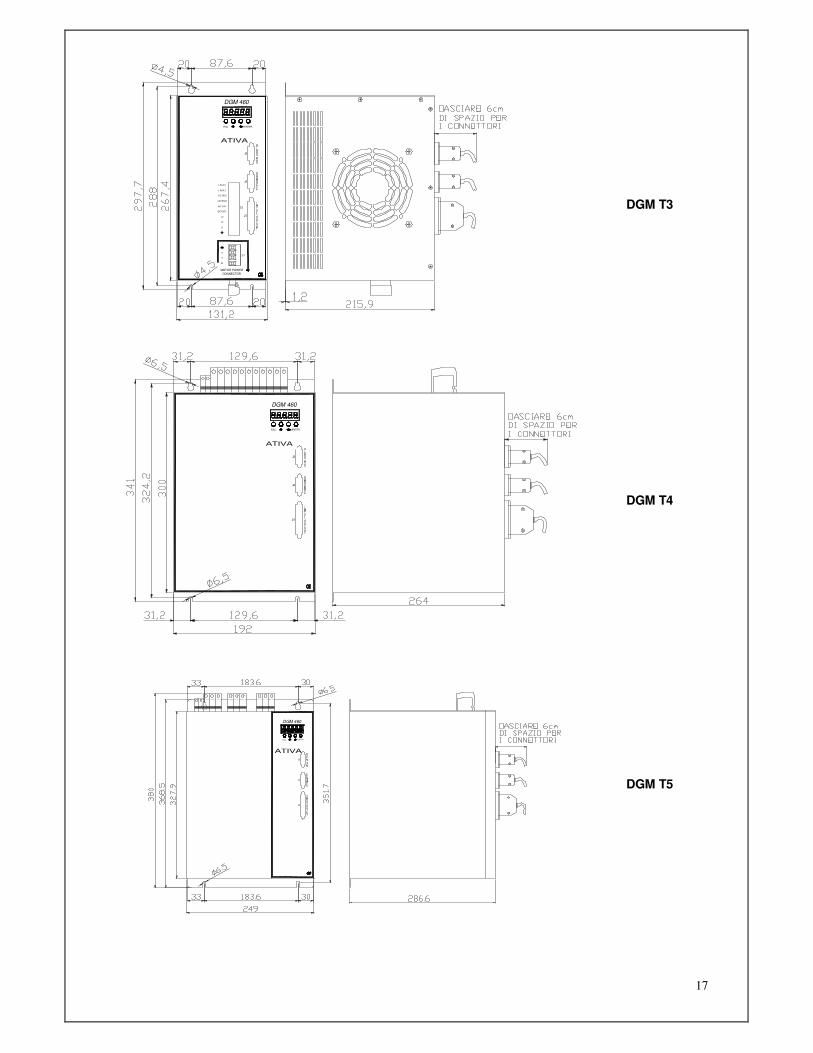
DGM T3
DGM T4
DGM T5
L1
V
W
U
J1
J2
+DC BUS
INT B.R.
EXT B.R.
L3
L2
L AUX 1
L AUX 2
-DC BUS
ESC
J5
J4
J3
ENTER
DGM 460
MOTOR POWER
CONNECTOR
J5
J4
J3
ENTERESC
DGM 460
J5
J4
ESC
J3
ENTER
DGM 460
ATIVA
ATIVA
ATIVA

18
5. Wiring harness and description of connections
5.1 Connector or power terminal board J1 and J2
1) Motor power connector The output terminals for the motor are: U, V, and W. Do not connect the power supply to the U, V, and W. Respect the order U, V, W, of the motor with the same order U, V, W, of the drive: The inversion of the phases do not invert the direction of rotation of the motor.
The connection to our servomotors has to be installed using the connector wired in the following way:
A
B C
D1
2
3 4
5
6
B05-B07 B10-B14-B20
POWER MOTORS B05-B07
MOTORS B10-B14-B20-B26
MOTORIS BSP-BSD
CABLES 4X1
CABLES 4X1.5 4X2.5
GROUND 6 D
G/V G/V
U 1 A 1 Black 1 Black 1 V 3 B 3 Black 2 Greay/Blu 2 W 5 C 4 Black 3 Brown 3
BSP-BSD

19
5.1.1 Description of the Motor power connector J1
1 PE - Terminal connected to the converter chassis
2 U - U Phase motor output
3 V - V Phase motor output
4 W - W Phase motor output
5.2 Power Supply connector J2 1) Main power supply Input power terminals are L1, L2, and L3. Power can be furnished directly by the electricity network provided that adapted to the drive, or it needs to put a transformer or an autotransformer. The choice of the transformer power supply has to be calculated using the following formula:
1) Get from the motor catalogue the power in KW at nominal speed or use the following formula:
T*N*6,8 N=max speed (RPM) P(KW)=------------------- where 0,9*60*1000 T=Nominal Torque
2) In case of multiaxes systems add the various power found and multiply this amount for a coefficient Kc<1 that consider the use in contemporary (the values more used are: 0,63 for 2 axes, 0,5 for 3 axes, 0,38 for 4 axes, 0,33 for 5, and 0,28 for 6).
3) Multiply the value obtained for a corrective coefficient that consider the system efficiency (1,2):
P(KW) =∑Pout * Kc * 1,2.
2) AC power supply for logic control Laux In DGM 460 input terminals for the power control logic are Laux1 and Laux2. Must be applied a voltage of 230Vac. DGM460 voltage range Laux is 200Vac - 400Vac. In DGM 240 input terminals for the power control logic are Laux1 and Laux2. Must be applied a voltage of 230Vac. DGM240 voltage range Laux is 110Vac - 230Vac. The power required is approximately 20VA.
You do not need an isolation transformer. 3) Braking resistor To connect the internal resistor make a jumper between +DC BUS input and INT BR input. To replace the internal resistor with an external braking resistor you have to remove the Jumper between +DC BUS input and INT BR input and connect the external braking resistor between the input +DC BUS and input EXT BR. 4) DC power supply Connect DC power to +DC BUS and –DC BUS inputs in case of DC feeding 5) Cables The choice of power supply cables has to be done considering the current absorbed from the motor. The section suggested for the drive models is the following:
DGM < 5A 1,0 mm² DGM 5/10 1,5 mm² DGM 10/20 2,5 mm² DGM 20/40 4,0 mm² DGM 35/70 6,0 mm² DGM 45/90 10,0 mm² DGM 75/150 25,0 mm²
20
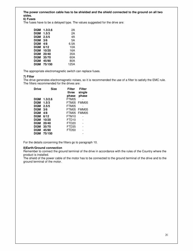
The power connection cable has to be shielded and the shield connected to the ground on all two sides. 6) Fuses The fuses have to be a delayed type. The values suggested for the drive are:
DGM 1.3/2.6 2A DGM 1.5/3 2A DGM 2.5/5 4A DGM 3/6 5A DGM 4/8 6.5A DGM 6/12 10A DGM 10/20 16A DGM 20/40 35A DGM 35/70 60A DGM 45/90 80A DGM 75/150 125A
The appropriate electromagnetic switch can replace fuses.
7) Filter The drive generates electromagnetic noises, so it is recommended the use of a filter to satisfy the EMC rule. The filters recommended for the drives are:
Drive Size Filter three phase
Filter single phase
DGM 1.3/2.6 FTM05 - DGM 1.5/3 FTM05 FMM05 DGM 2.5/5 FTM05 - DGM 3/6 FTM05 FMM05 DGM 4/8 FTM05 FMM05 DGM 6/12 FTM10 - DGM 10/20 FTD10 - DGM 20/40 FTD20 - DGM 35/70 FTD35 - DGM 45/90 FTD50 - DGM 75/150 -
For the details concerning the filters go to paragraph 10.
8)Earth/Ground connection Remember to connect the ground terminal of the drive in accordance with the rules of the Country where the product is installed. The shield of the power cable of the motor has to be connected to the ground terminal of the drive and to the ground terminal of the motor.
21
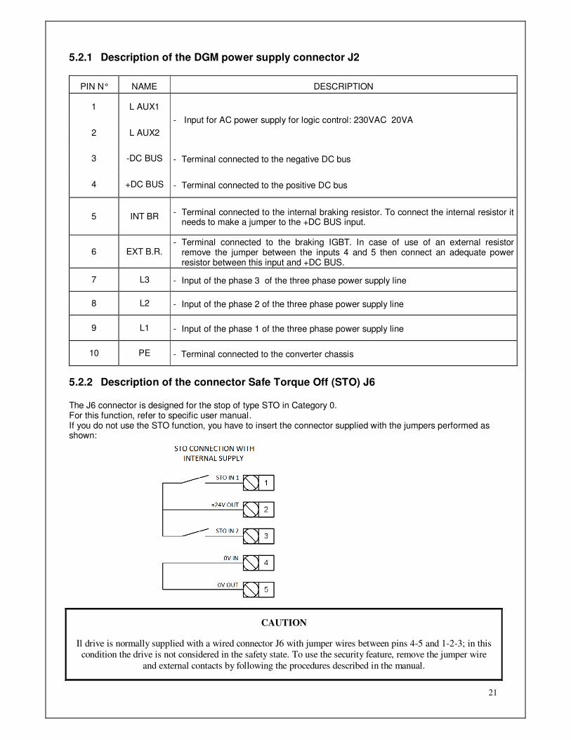
5.2.1 Description of the DGM power supply connector J2
PIN N° NAME DESCRIPTION
1 L AUX1
2 L AUX2
- Input for AC power supply for logic control: 230VAC 20VA
3 -DC BUS - Terminal connected to the negative DC bus
4 +DC BUS - Terminal connected to the positive DC bus
5 INT BR - Terminal connected to the internal braking resistor. To connect the internal resistor it
needs to make a jumper to the +DC BUS input.
6 EXT B.R. - Terminal connected to the braking IGBT. In case of use of an external resistor
remove the jumper between the inputs 4 and 5 then connect an adequate power resistor between this input and +DC BUS.
7 L3 - Input of the phase 3 of the three phase power supply line
8 L2 - Input of the phase 2 of the three phase power supply line
9 L1 - Input of the phase 1 of the three phase power supply line
10 PE - Terminal connected to the converter chassis
5.2.2 Description of the connector Safe Torque Off (STO) J6 The J6 connector is designed for the stop of type STO in Category 0. For this function, refer to specific user manual. If you do not use the STO function, you have to insert the connector supplied with the jumpers performed as shown:
CAUTION
Il drive is normally supplied with a wired connector J6 with jumper wires between pins 4-5 and 1-2-3; in this
condition the drive is not considered in the safety state. To use the security feature, remove the jumper wire
and external contacts by following the procedures described in the manual.

22
5.3 Resolver connector J4
1) Resolver cables
This connection have to be well executed using a special type of cable composed by a 3 twisted pairs, single shielded and sorted in a further shield. A further pair of the cable is used to connect the thermal sensor of the motor. The conductors can have a minimum section of 0.22mm² and connection maximum of 50 meters between resolver and drives
2) Connector resolver drive side J4 The type of movable connector to assemble with the cable is a type HD SUB female 15pins. The pins description is the following:
Pin N Name Description
1 Excit+ Output Terminal for the resolver power supply 2 Excit-
10 Sin+ Input terminal of resolver Sin signal 5 Sin- 4 Cos+ Input terminal of resolver Cos signal 3 Cos- 8 Ptc Terminal for the connection of the thermal motor sensor 9 Ptc 6 Shield Connection al of the shield of the resolver cable
MOTORS B10-B14-B20-B26
MOTORS B05-B07

23
3)Parallel between resolver connector pins J4 and motor connector N Pin name of
connector type MS02A 12-10P for motors B10, B14,B20
Pin number of connector type
AAGF LSR12 for motors B05, B07
Description When cable colour
furnished is
GREEN 1 F 6 Excit+ WHITE 2 D 4 Excit- BROWN
10 E 5 Sin+ BLUE 5 C 3 Sin- RED 4 A 1 Cos+ GREEN 3 B 2 Cos- YELLOW 9 H 8 Ptc GRAY 8 G 7 Ptc ROSE 6 - - SHIELD SHIELD J,K 9,10,11,12 FREE
5.4 Simulated Encoder Connection J5 1) Signals available on connector J5 are those typical of an incremental encoder with a 5V “Line Driver”
output. The number of pulses/rotation available can be selected from the converter keypad or from PC Interface Accord® and it can be 256 – 1024 – 4096 –16384. The movable connector for this application has to be of type 44 poles HDSUB male. The pins description is the following:
Pin N. Name Description 6 /CHZ Line Driver Outputs Channel Zero 21 CHZ 34 /CHB Line Driver Outputs Channel B 5 CHB 20 /CHA Line Driver Outputs Channel A 35 CHA 36 0VL Common
Note A: The Drive can be furnished also with a Line Driver fed with an external Voltage from 5V to 24VDC so that it can obtained logical signal Line Driver up to 24V.
1) For noises immunity it’s necessary to use a shielded cable with twisted pair 2) For input signals it has to be used an input charged with about 10mA.
24
PORTA
CONVERTITORE
RS232/485
RS
232-P
C
TLC 485
9
26
1
8
73
4
5
SERIALE PC
15
14
13
12
116
7
89
2
1
4
3
510
CONNETTORE9 VIE FEMMINA
VISTA LATO SALDATURE
CONNETTORE15 VIE MASCHIO
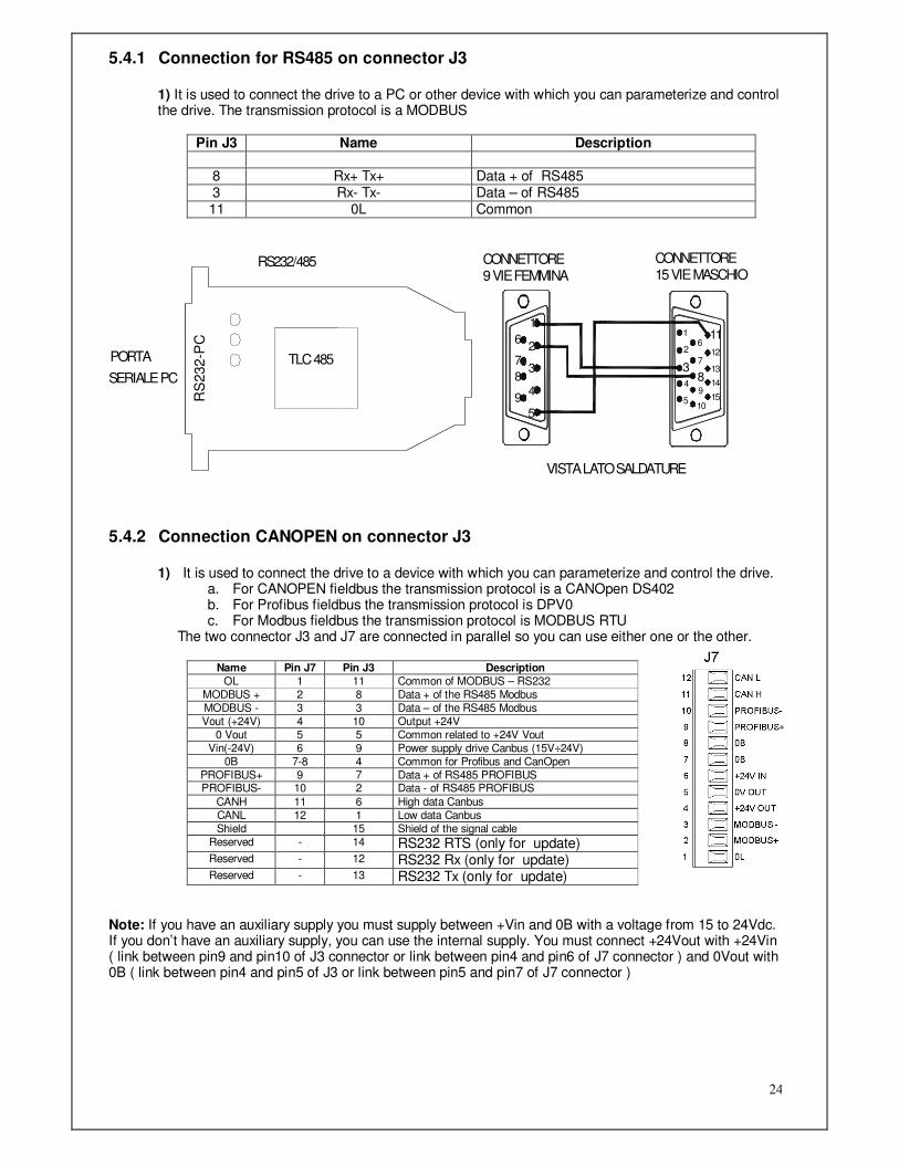
5.4.1 Connection for RS485 on connector J3
1) It is used to connect the drive to a PC or other device with which you can parameterize and control the drive. The transmission protocol is a MODBUS
Pin J3 Name Description
8 Rx+ Tx+ Data + of RS485 3 Rx- Tx- Data – of RS485 11 0L Common
5.4.2 Connection CANOPEN on connector J3
1) It is used to connect the drive to a device with which you can parameterize and control the drive. a. For CANOPEN fieldbus the transmission protocol is a CANOpen DS402 b. For Profibus fieldbus the transmission protocol is DPV0 c. For Modbus fieldbus the transmission protocol is MODBUS RTU
The two connector J3 and J7 are connected in parallel so you can use either one or the other.
Name Pin J7 Pin J3 Description
OL 1 11 Common of MODBUS – RS232 MODBUS + 2 8 Data + of the RS485 Modbus MODBUS - 3 3 Data – of the RS485 Modbus Vout (+24V) 4 10 Output +24V
0 Vout 5 5 Common related to +24V Vout Vin(-24V) 6 9 Power supply drive Canbus (15V÷24V)
0B 7-8 4 Common for Profibus and CanOpen PROFIBUS+ 9 7 Data + of RS485 PROFIBUS PROFIBUS- 10 2 Data - of RS485 PROFIBUS
CANH 11 6 High data Canbus CANL 12 1 Low data Canbus Shield 15 Shield of the signal cable
Reserved - 14 RS232 RTS (only for update) Reserved - 12 RS232 Rx (only for update) Reserved - 13 RS232 Tx (only for update)
Note: If you have an auxiliary supply you must supply between +Vin and 0B with a voltage from 15 to 24Vdc. If you don’t have an auxiliary supply, you can use the internal supply. You must connect +24Vout with +24Vin ( link between pin9 and pin10 of J3 connector or link between pin4 and pin6 of J7 connector ) and 0Vout with 0B ( link between pin4 and pin5 of J3 or link between pin5 and pin7 of J7 connector )

25
5.4.3 Connection for RS232 (used only to update the firmware) 1) It is used to connect the drive to a PC and with a dedicated software allows you to reprogram the drive.
Pin J3
Name Description Pin Standard Connector DB9 for PC
11 GND Common of signals 5 12 Tx Data in transmission(Out) 2 13 Rx Data in reception (In) 3 14 RTS Request to send (In) 7
5.5 Connection for frequency speed reference on connector J5 1) It is used if you want to use as a speed reference a signal of frequency. Moreover it’s the input for
the master speed and position reference in case of use of application program “Electronic gear box” and “ Electronic cam”. It supports the following types of signals:
• Differential line drive 5V
• Push-pull 5V • Open collector 5V
• NPN or PNP At 12V (with serie resistor 680 ohm 1/4W) or 24V (with serie resistor 1K8 1/2W)
Three way of working are provided: Mode 1: When two signals come from two channel of a real or a simulated encoder; Mode 2: A signal represent the speed reference ( in frequency) and the other the direction. Mode 3: The reference pulses are sent on one channel or the other depending on the desired direction of rotation. In the DGM with Hardware Version = 1, the unused channel must remain inactive state (Pin 38 or Pin 37 at the same potential or negative potential with respect pins 23 and 8). What drives with hardware version "0" or without hardware release the unused channel must remain in the active state (Pin 38 or Pin 37 at a positive potential with respect pins 23 and 8). To see specification of these 3 way of working and related settings please refer to paragraph 7.2.4 at the voice ”main frequency reference”. The correct movable connector to use is type HDSUB 44 pins male. Pins description is the following:
Pin N. Name Description 38 CH1 23 /CH1
Frequency differential input
37 CH2 8 /CH2
Frequency or direction differential input
36 0VL Common 22 +5VL Out +5 Volt
2) For noises immunity it’s necessary to use a shielded cable with twisted pairs. Following are some application schemes:

26
5.6 J5 connector inputs
Pin Name Type Description
1
16
Ref-
Ref+
Differential analog input
Main input for speed reference. This reference is enabled and programmed using an operator panel.( see paragraph 7.2.4 )
Input signal of ±10V digitalized using an 16 bits analog/digital converter.
18 Com sig Common of analog signals
17
32
Ref aux-
Ref aux+
Differential analog input
Auxiliary reference input. This reference is enabled and programmed using an Keypad. (see paragraph 7.2.4 and 7.2.5 )
Enter with a ±10V signal digitalized using an analog/digital 10 bits converter.Depending on the settling it can become: Analog auxiliary reference of speed Analog reference of torque limit Analog reference of torque It can do the functions of the 'digital input I8 (Enable JOG mode "Axis Electric / Position") by connecting pin 32 to GND and providing a +24 V on pin 17.
2
31
Ref aux2-
Ref aux2+
Differential analog input
This input is enabled and programmed via the keypad. Enter with a ± 10V signal that is digitized by an 10 bits analog to digital converter. As of today it is not used as analog input. It can do the functions of the digital input I9 connecting pin 31 to GND and providing a +24 V on pin 2.
25 I0
Ena Digital Input
A high signal enables the power to the motor that goes in lock shaft. Drive shows a message ENA in d.0000
40 I1 Digital Input
Digital input which functionality is defined by the type of control selected. This input can be enabled and set using the drive keyboard. (See paragraph 7.2.10).
11 I2 Digital Input
Digital input which functionality is defined by the type of control selected. This input can be enabled and set using the drive keyboard. (See paragraph 7.2.10).
26 I3 Digital Input
Digital input which functionality is defined by the type of control selected. This input can be enabled and set using the drive keyboard. (See paragraph 7.2.10).

27
41 I4
Reset Digital Input
Input used to reset some alarms. The reset is done giving a high level signal. This input can be enabled and set using the drive keyboard. (See paragraph 7.2.10).
12 I5
Start/Stop Digital Input
A high signal enables the speed reference, the current reference and position reference. Drive shows message “Run” in d.0000
27 I6 Digital Input
Digital input which functionality is defined by the type of control selected. This input can be enabled and set using the drive keyboard. (see paragraph 7.2.10).
42 I7 Digital Input
Digital input which functionality is defined by the type of control selected. This input can be enabled and set using the drive keyboard. (see paragraph 7.2.10).
39 +24 I/O +24VDC Input
+24V inputs to feed drive control digital outputs. If not fed the drive shows alarms FA11 ( that means :+24 not detected).
10 Gnd I/O Gnd Ground input for I/O feed.
5.7 J5 connector outputs Pin Name Type Description
33 +10 Output +10V Stabilized output +10V to feed an additional potentiometer. (max current 15mA)
18 Com sig Common of analog signals
3 -10 Output -10V Stabilized output -10V to feed an additional potentiometer. (max current 15mA)
19 Out An1 Analog Output
Output used in case of monitoring or for possible tool. It can show (see paragraph 7.2.9):
• Speed reference • Current reference
• Speed measured
• Current measured
4 Out An2 Analog Output
Output used in case of monitoring or for possible tool. (See description Out An1)
44 Out 0
I2t Digital Output
Active when one of the following thermal protection happened:
• Thermal image of the motor
• Thermal image of the drive
• Thermal image of the breaking resistor • Motor Thermal sensor intervention
• DriveThermal sensor intervention
30 Out 1
Drive OK Digital Output
Active in presence of no alarm activity. Not operative when the drive locks.
15 Out 2
Zero Speed / Torque limit
Digital Output
Zero speed: Active when motor runs under the threshold of speed set in parameter S.5002 for a time bigger than the value set in S.5003. Torque limit: Active when the drive limit the current
43 Out 3 Brake
Digital Output
It’s activated when drive is Enable (Ena). See paragraph 7.2.11 at parameters S.8xxx
29 Out 4 Target
reached
Digital Output
In “position” mode this output give the signal of position reached.
14 Out 5
Secure power disable
Digital Output
It’s active when the power go off on connector J6 related to Secure Power Disable
13 28
Drive OK Drive OK
Free (Dry) contact Output
The contact is closed when no alarms are on. It opens when an alarm stucks the drive.

28
24 +24V Vout +24Vdc +24V Output that can be used to feed the circuit of Digital or analog inputs.
9 Gnd Vout Gnd of voltage reference Vout 24V Note: for electrical details go to chapter 3.1
29
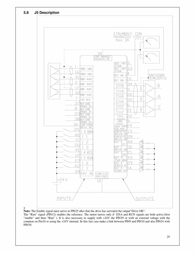
5.8 J5 Description
5 Note: The Enable signal must arrive at PIN25 after that the drive has activated the output“Drive OK”.
The “Run” signal (PIN12) enables the reference. The motor moves only if ENA and RUN signals are both active.(first
“enable” and then “Run” ). It is also necessary to supply with +24V the PIN39 or with an external voltage with the
common on Pin10 or using the +24V internal. In this last case make a link between PIN9 and PIN10 and also PIN24 with
PIN39.

30
J5 pins number Function description 1 Differential inverting Input main speed reference 16 Differential not-inverting Input main speed reference 31 Differential not-inverting aux reference2 2 Differential inverting aux reference2 17 Differential inverting input aux reference1 32 Differential not-inverting input aux reference1 3 Output -10V stabilized (15ma) 18 Analog signals common 0S 33 Output +10V regulated (15ma) 4 Analog output out2 19 Analog output out1 34 /CHB line driver output channel B simulated encoder 5 CHB line driver output channel B simulated encoder 20 /CHA line driver output channel A simulated encoder 35 CHA line driver output channel A simulated encoder 6 /CHZ line driver output channel Zero simulated encoder 21 CHZ line driver output channel Zero simulated encoder 36 Analog signals common OL 7 +5V Output (join K3 point with soft soldering) 22 +5V Output 37 Line driver Frequency speed reference input B+ (Direction) 8 Line driver Frequency speed reference input B- (Direction) 23 Line driver Frequency speed reference input A- 38 Line driver Frequency speed reference input A+ 9 GND Vout Common for pin 24 24 +24 Vout (50 mA) 39 +24V I/O Input +24V to supply input/output 10 GND I/O common for digital input/output 25 Digital input i0 (Drive Enable) 40 Digital input i1 11 Digital input i2 26 Digital input i3 41 Digital input i4 (Reset) 12 Digital input i5 (Run) 27 Digital input i6 42 Digital input i7 13 Relay contact of DriveOK 28 Relay contact of DriveOK 43 Digital output out3 (Motor Brake) 14 Digital output out5 (Secure Power Disable) 29 Digital output out4 (Reached position) 44 Digital output out0 (I2t) 15 Digital output out2 (Motor Off) 30 Digital output out1 (DriveOK)
31
6. Operator Panel
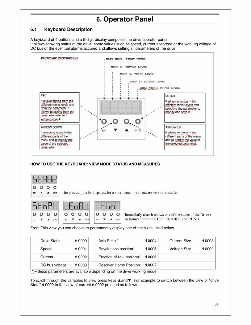
6.1 Keyboard Description A keyboard of 4 buttons and a 5-digit display composes the drive operator panel. It allows showing status of the drive, some values such as speed, current absorbed or the working voltage of DC bus or the eventual alarms accured and allows setting all parameters of the drive.
HOW TO USE THE KEYBOARD: VIEW MODE STATUS AND MEASURES
From This view you can choose to permanently display one of the sizes listed below.
(*)= these parameters are available depending on the drive working mode. To scroll through the variables to view press keys and. For example to switch between the view of “drive State” d.0000 to the view of current d.0002 proceed as follows:
The product just lit dispalys, for a short time, the firmware version installed
Immediatly after it shows one of the states of the Drive (
in figures the state STOP, ENABLE and RUN )
Drive State d.0000 Axis Ratio * d.0004 Current Size d.0008
Speed d.0001 Revolutions position* d.0005 Voltage Size d.0009
Current d.0002 Fraction of rev. position* d.0006
DC bus voltage d.0003 Resolver Home Position d.0007
32
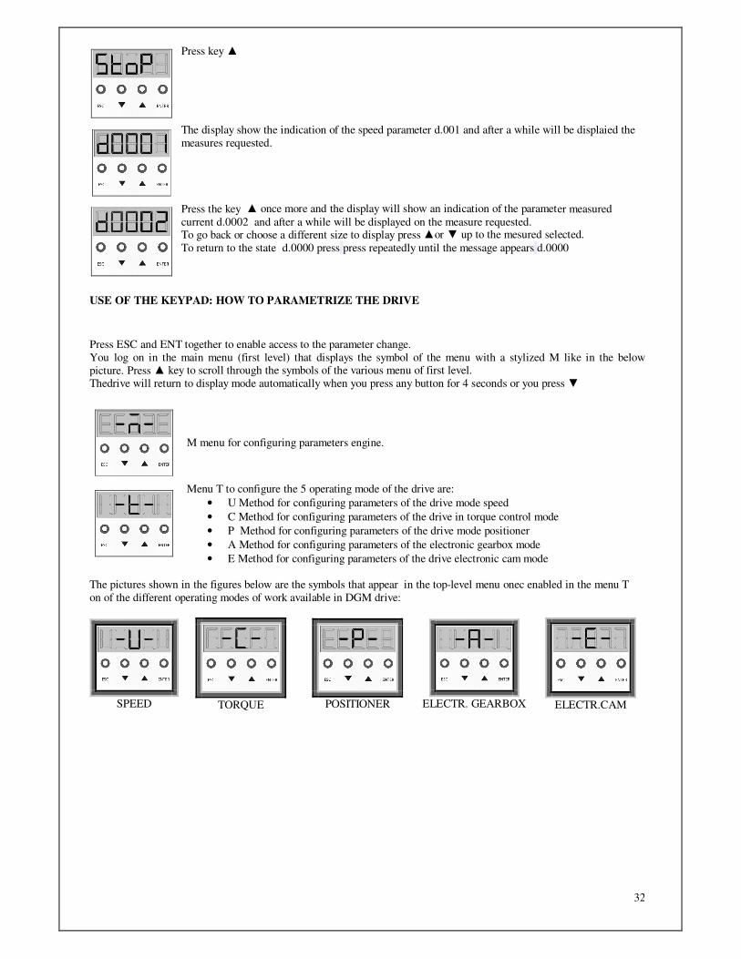
USE OF THE KEYPAD: HOW TO PARAMETRIZE THE DRIVE
Press key
The display show the indication of the speed parameter d.001 and after a while will be displaied the
measures requested.
Press the key once more and the display will show an indication of the parameter measured
current d.0002 and after a while will be displayed on the measure requested. To go back or choose a different size to display press or up to the mesured selected.
To return to the state d.0000 press press repeatedly until the message appears d.0000
Press ESC and ENT together to enable access to the parameter change.
You log on in the main menu (first level) that displays the symbol of the menu with a stylized M like in the below
picture. Press key to scroll through the symbols of the various menu of first level. Thedrive will return to display mode automatically when you press any button for 4 seconds or you press
M menu for configuring parameters engine.
Menu T to configure the 5 operating mode of the drive are:
• U Method for configuring parameters of the drive mode speed
• C Method for configuring parameters of the drive in torque control mode
• P Method for configuring parameters of the drive mode positioner
• A Method for configuring parameters of the electronic gearbox mode
• E Method for configuring parameters of the drive electronic cam mode
The pictures shown in the figures below are the symbols that appear in the top-level menu onec enabled in the menu T
on of the different operating modes of work available in DGM drive:
SPEED
TORQUE
POSITIONER
ELECTR. GEARBOX
ELECTR.CAM

33
USE OF THE KEYPAD: MENU DI SECOND, THIRD LEVEL AND PARAMETERS LEVEL
From each top-level menu you can access a second menu level and below a third level menu to be able to access the
fourth floor where you will find the final parameters of the drive. The way to access the structure is exemplified in the
following tutorial in which you want to set the drive mode “positioner” and want to set the number of revolutions of the
first position (parameter P2201)
O. Menu to configure the digital outputs
I.Menu to configure the digital inputs
S (Setup). Menu to adjust the drive
H. Menu available only for authorized operators.
Menu
Mode P
With arrows and move along the first level until the symbol T appears as in next image.
The menu T allows to enable the the different operating mode of the drive.
Press ENT to access the second level menu and scroll with and the various modes of
operation available shown here below. Stop when you find the symbol P positioner and press
ENT to enable the operating mode position (as you can see in the picture) . This will enabled the
parameters “positioner” located in the first level. Press ESC to return to the T menu at the first level.
1.
Now move from menu T (Type) with the arrows and along the first level to try the new
menu "P" of parameters of the function “positioner.”
2.
Select the menu P (positioner) pressing the button ENT to access to the second level menu of the
positioner.

34
3.
Now it will be
displaied the
parameter P.0000 on
the left of the display
4.
To access the parameter P2201 Press key
twice and change the first digit.It will appear P.2.
Press ENT to confirm the first digit. Now you
can change the second digit.
5.
Press key twice
and change the second
digit, it will appear
P.22
Press ENT to enter
the third digit that
will be zero P.220
and press ENT again
to enter the fourth
digit. 6.
Press key once to
display the value 1 so
as to compose P2201.
Press ENT to enter the
parameter P.2201.
Set the desired value (whole number of revolutions of the first position of the cyclical positioner) and press ENT. To go
back at different levels, press the ESC key several times until reaching the desired level. All numeric parameters, such as in this example, update the drive immediately as soon as they are modified. To save the
data, you need to confirm with ENT, otherwise just exit with the ESC key to reset the parameters previously saved.
35
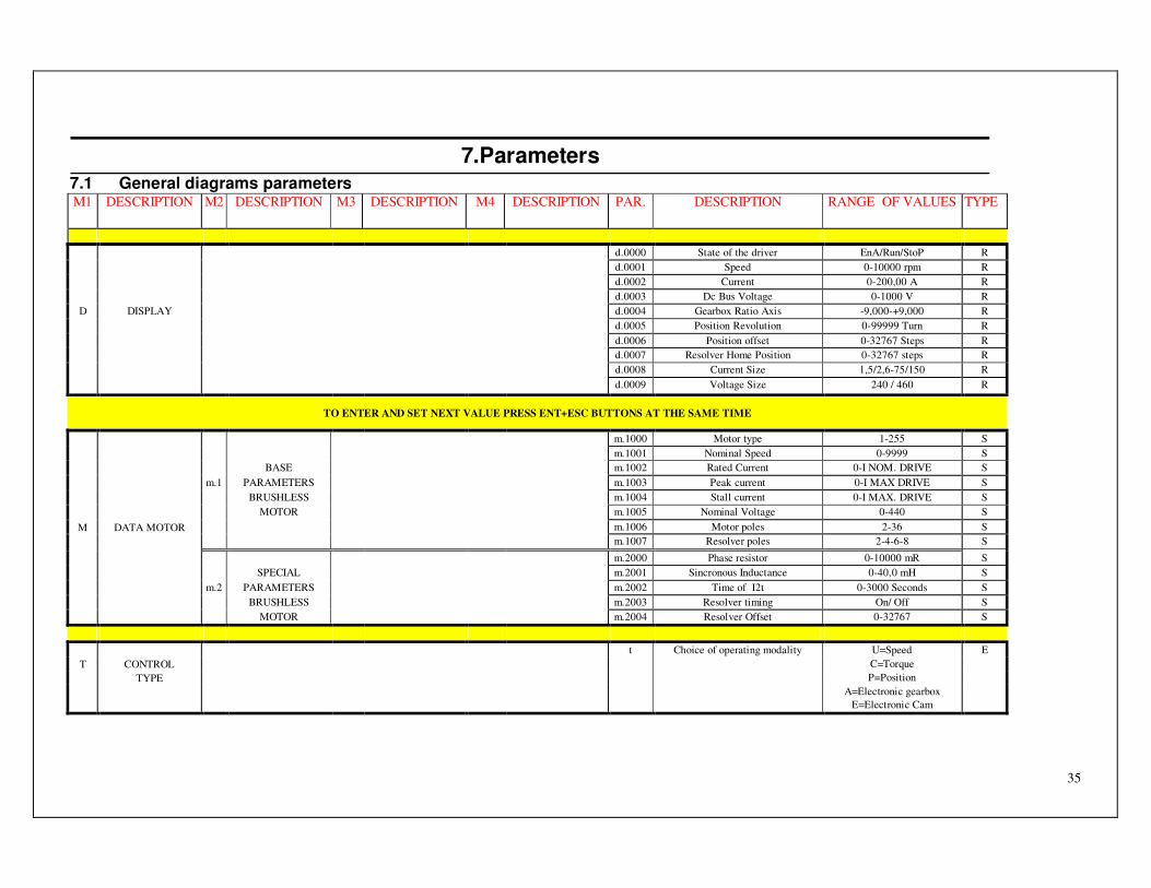
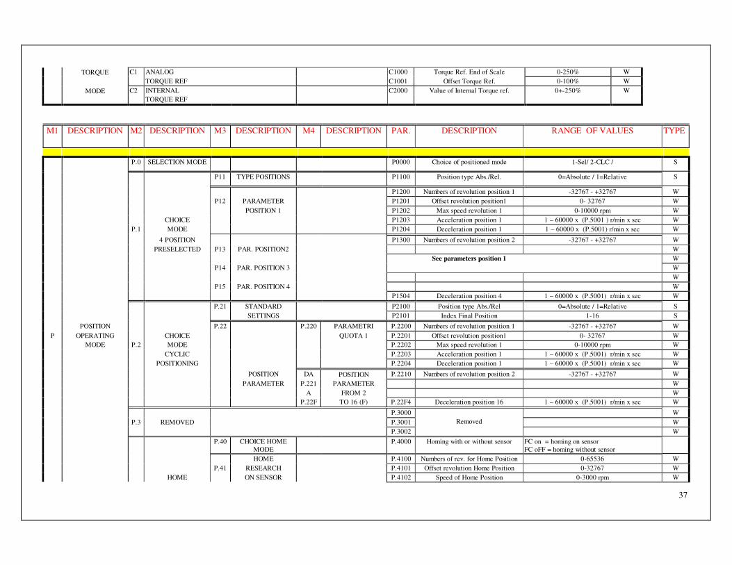
7.Parameters 7.1 General diagrams parameters M1 DESCRIPTION M2 DESCRIPTION M3 DESCRIPTION M4 DESCRIPTION PAR. DESCRIPTION RANGE OF VALUES TYPE
d.0000 State of the driver EnA/Run/StoP R
d.0001 Speed 0-10000 rpm R
d.0002 Current 0-200,00 A R
d.0003 Dc Bus Voltage 0-1000 V R
D DISPLAY d.0004 Gearbox Ratio Axis -9,000-+9,000 R
d.0005 Position Revolution 0-99999 Turn R
d.0006 Position offset 0-32767 Steps R
d.0007 Resolver Home Position 0-32767 steps R
d.0008 Current Size 1,5/2,6-75/150 R
d.0009 Voltage Size 240 / 460 R
TO ENTER AND SET NEXT VALUE PRESS ENT+ESC BUTTONS AT THE SAME TIME
m.1000 Motor type 1-255 S
m.1001 Nominal Speed 0-9999 S
BASE m.1002 Rated Current 0-I NOM. DRIVE S
m.1 PARAMETERS m.1003 Peak current 0-I MAX DRIVE S
BRUSHLESS m.1004 Stall current 0-I MAX. DRIVE S
MOTOR m.1005 Nominal Voltage 0-440 S
M DATA MOTOR m.1006 Motor poles 2-36 S
m.1007 Resolver poles 2-4-6-8 S
m.2000 Phase resistor 0-10000 mR S
SPECIAL m.2001 Sincronous Inductance 0-40,0 mH S
m.2 PARAMETERS m.2002 Time of I2t 0-3000 Seconds S
BRUSHLESS m.2003 Resolver timing On/ Off S
MOTOR m.2004 Resolver Offset 0-32767 S
t Choice of operating modality U=Speed E
T CONTROL C=Torque
TYPE P=Position
A=Electronic gearbox
E=Electronic Cam
36
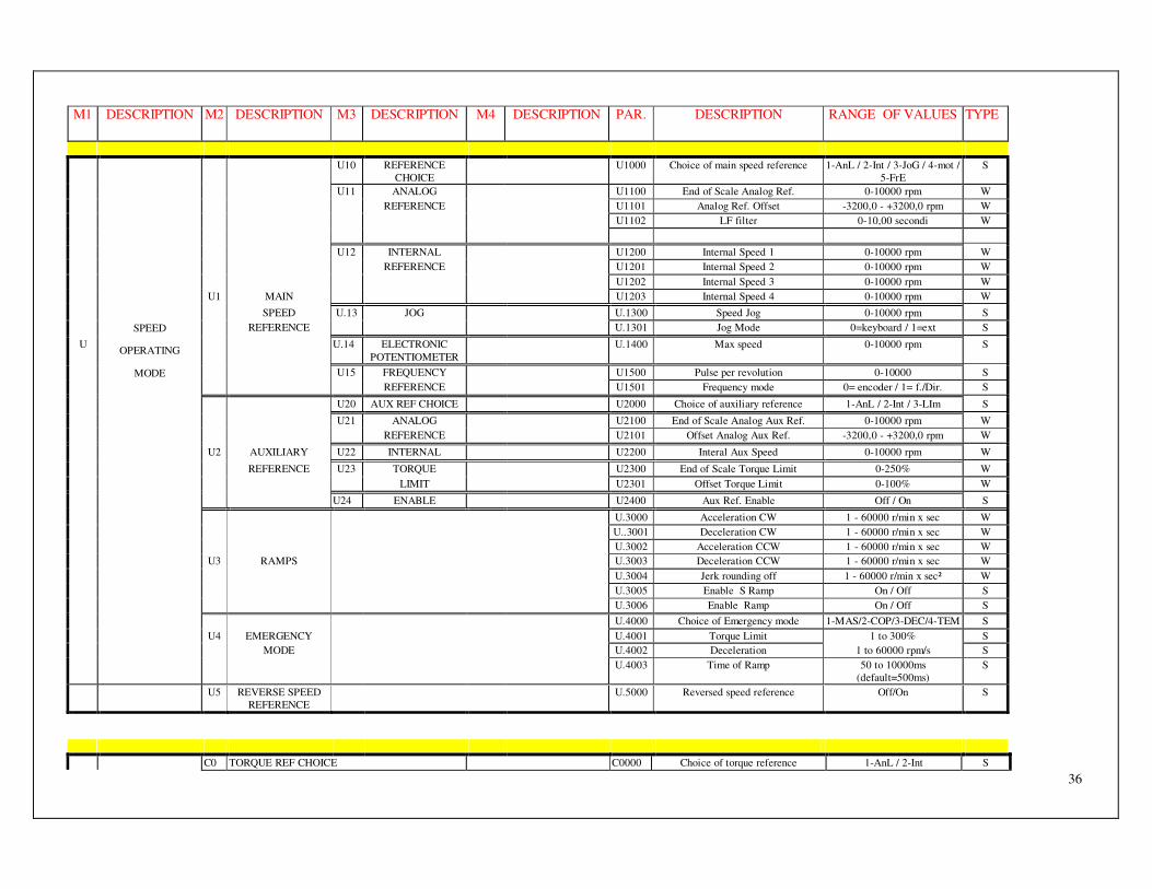
M1 DESCRIPTION M2 DESCRIPTION M3 DESCRIPTION M4 DESCRIPTION PAR. DESCRIPTION RANGE OF VALUES TYPE
U10 REFERENCE
CHOICE
U1000 Choice of main speed reference 1-AnL / 2-Int / 3-JoG / 4-mot /
5-FrE
S
U11 ANALOG U1100 End of Scale Analog Ref. 0-10000 rpm W
REFERENCE U1101 Analog Ref. Offset -3200,0 - +3200,0 rpm W
U1102 LF filter 0-10,00 secondi W
U12 INTERNAL U1200 Internal Speed 1 0-10000 rpm W
REFERENCE U1201 Internal Speed 2 0-10000 rpm W
U1202 Internal Speed 3 0-10000 rpm W
U1 MAIN U1203 Internal Speed 4 0-10000 rpm W
SPEED U.13 JOG U.1300 Speed Jog 0-10000 rpm S
SPEED REFERENCE U.1301 Jog Mode 0=keyboard / 1=ext S
U OPERATING
U.14 ELECTRONIC
POTENTIOMETER
U.1400 Max speed 0-10000 rpm S
MODE U15 FREQUENCY U1500 Pulse per revolution 0-10000 S
REFERENCE U1501 Frequency mode 0= encoder / 1= f./Dir. S
U20 AUX REF CHOICE U2000 Choice of auxiliary reference 1-AnL / 2-Int / 3-LIm S
U21 ANALOG U2100 End of Scale Analog Aux Ref. 0-10000 rpm W
REFERENCE U2101 Offset Analog Aux Ref. -3200,0 - +3200,0 rpm W
U2 AUXILIARY U22 INTERNAL U2200 Interal Aux Speed 0-10000 rpm W
REFERENCE U23 TORQUE U2300 End of Scale Torque Limit 0-250% W
LIMIT U2301 Offset Torque Limit 0-100% W
U24 ENABLE U2400 Aux Ref. Enable Off / On S
U.3000 Acceleration CW 1 - 60000 r/min x sec W
U..3001 Deceleration CW 1 - 60000 r/min x sec W
U.3002 Acceleration CCW 1 - 60000 r/min x sec W
U3 RAMPS U.3003 Deceleration CCW 1 - 60000 r/min x sec W
U.3004 Jerk rounding off 1 - 60000 r/min x sec² W
U.3005 Enable S Ramp On / Off S
U.3006 Enable Ramp On / Off S
U.4000 Choice of Emergency mode 1-MAS/2-COP/3-DEC/4-TEM S
U4 EMERGENCY U.4001 Torque Limit 1 to 300% S
MODE U.4002 Deceleration 1 to 60000 rpm/s S
U.4003 Time of Ramp 50 to 10000ms
(default=500ms)
S
U5 REVERSE SPEED
REFERENCE
U.5000 Reversed speed reference Off/On S
C0 TORQUE REF CHOICE C0000 Choice of torque reference 1-AnL / 2-Int S
37
TORQUE C1 ANALOG C1000 Torque Ref. End of Scale 0-250% W
TORQUE REF C1001 Offset Torque Ref. 0-100% W
MODE C2 INTERNAL C2000 Value of Internal Torque ref. 0+-250% W
TORQUE REF
M1 DESCRIPTION M2 DESCRIPTION M3 DESCRIPTION M4 DESCRIPTION PAR. DESCRIPTION RANGE OF VALUES TYPE
P.0 SELECTION MODE P0000 Choice of positioned mode 1-Sel/ 2-CLC / S
P11 TYPE POSITIONS P1100 Position type Abs./Rel. 0=Absolute / 1=Relative S
P1200 Numbers of revolution position 1 -32767 - +32767 W
P12 PARAMETER P1201 Offset revolution position1 0- 32767 W
POSITION 1 P1202 Max speed revolution 1 0-10000 rpm W
CHOICE P1203 Acceleration position 1 1 – 60000 x (P.5001 ) r/min x sec W
P.1 MODE P1204 Deceleration position 1 1 – 60000 x (P.5001) r/min x sec W
4 POSITION P1300 Numbers of revolution position 2 -32767 - +32767 W
PRESELECTED P13 PAR. POSITION2 W
See parameters position 1 W
P14 PAR. POSITION 3 W
W
P15 PAR. POSITION 4 W
P1504 Deceleration position 4 1 – 60000 x (P.5001) r/min x sec W
P.21 STANDARD P2100 Position type Abs./Rel 0=Absolute / 1=Relative S
SETTINGS P2101 Index Final Position 1-16 S
POSITION P.22 P.220 PARAMETRI P.2200 Numbers of revolution position 1 -32767 - +32767 W
P OPERATING CHOICE QUOTA 1 P.2201 Offset revolution position1 0- 32767 W
MODE P.2 MODE P.2202 Max speed revolution 1 0-10000 rpm W
CYCLIC P.2203 Acceleration position 1 1 – 60000 x (P.5001) r/min x sec W
POSITIONING P.2204 Deceleration position 1 1 – 60000 x (P.5001) r/min x sec W
POSITION DA POSITION P.2210 Numbers of revolution position 2 -32767 - +32767 W
PARAMETER P.221 PARAMETER W
A FROM 2 W
P.22F TO 16 (F) P.22F4 Deceleration position 16 1 – 60000 x (P.5001) r/min x sec W
P.3000 W
P.3 REMOVED P.3001 W
P.3002
Removed
W
P.40 CHOICE HOME
MODE
P.4000 Homing with or without sensor FC on = homing on sensor
FC oFF = homing without sensor
HOME P.4100 Numbers of rev. for Home Position 0-65536 W
P.41 RESEARCH P.4101 Offset revolution Home Position 0-32767 W
HOME ON SENSOR P.4102 Speed of Home Position 0-3000 rpm W

38
P.4 POSITION P.4103 Limit switch Stop / Direction. 1=CW / 2= CCW S
P.4104 Enable/Disable search zero Mark On/Off S
PARAMETERS P.42 HOME P.4200 Direction. Home Position research 0= shorted path ; 1=CW ; 2=CCW S
RESEARCH P.4201 Offset Home Positin 0-32767 W
WITHOUT SENSOR P.4202 Speed of Home Position 0-3000 rpm W
P.5 PARAMETERS P.5000 Jerk (S shape acceleration) 1 – 60000x(P.5001) r/min x sec² S
POSITIONER P.5001 Acc. Dec. Multiplier value 0-100 S
M1 DESCRIPTION M2 DESCRIPTION M3 DESCRIPTION M4 DESCRIPTION PAR. DESCRIPTION RANGE OF VALUES TYPE
P.5002 Ramp Type Rs=S ramp; Rn=linear ramp; RnC=linear
continuous
S
P.5003 Position Reached advance timing 0,00-60,00 sec. S
P.6 CHOICE OF P.6000 Enable/Disable home research On/Off S
CONTROL TYPE
P.6001 Control Mode CTR-P=position S
At reached position CTR-U=speed
P.6002 Running Mode at the restart after a
stop, out of position (F19)
0=Wait H.P. ;1=present position;2=Next
position-3=Reset Origin
S
P.6003 Enable/disable ramp in case of forced stop (removing the Start)
On/Off S
P POSITION P.7 PARAMETER P.7000 Choice of sensor RESOLVER / ENCODER S
OPERATING POSITION Of position
MODE SENSOR P.7001 Number of pulses per revolution 100-65535 S
External encoder
P.7002 Number of pulses external encoder 100-65535 S
For a motor revolution
A.0 CHOICE RATIO A.0000 Choice ratio type 1= External; 2= selected
A.1 EXTERNAL RATIO
BY UP-DOWN
A.1000 Delta Ratio for time unit 0,001 - 1,000 S
COMMAND A.1001 Time Unit for Delta Ratio 0,01 - 10,00 sec S
A.2 SELECTABLE A.2000 Ratio 1 0,001 - 8,000 W
ELECTRONIC
GEAR BOX
INTERNAL A.2001 Ratio 2 0,001 - 8,000 W
A OPERATING RATIOS A.2002 Ratio 3 0,001 - 8,000 W
MODE A.2003 Ratio 4 0,001 - 8,000 W
A.3 AXIS A.3000 Pulses for revolution 200 - 16384 S
PARAMETER A.3001 Frequency mode 1=CHA CHB Encoder; 1=Pulsef/Direction;
3= PulseCW/CCW
S
A.3002 Choice Input I2: Limit switch CCW
or phase shift-
Fcccu = Limit switch CCW
SFAS- = Phase shift -
S
A.3003 Pulses target reached 1-65535 W
A.4 PHASE SHIFT A.4000 Phase shift speed 0 - 200% S
AXIS A.4001 Phase shift speed ramp 1 - 10000 rp/min x sec S

39
PARAMETER A.4002 Max lenght of Phase shift 0,01 - 10,00sec S
E.1 CAM SETTING E.1001 Cam points 16-256 S
E.1002 Table index 0-255 S
E.1003 Cam data 0-65535 S
E.2 CAM SETTING E.2001 Cam Mode 1-AC1, 2-CLC S
E.2002 Number of Cams 1-60000 S
E.2003 Encoder Numerator -32768 - +32767 W
E.2004 Encoder Denominator 1-65535 W
E.2005 Frequency Mode 1-a b / 2-Fr9 S
E.2006/7 Master Module 0-1048575 S
E.2008/9 Slave Module 0-4194303 S
E.200A/
B
Syncronism Phase 0-4194303 W
E.200C Enable Sinchronism On-Off S
E.200d Type contact sinchronism 0=NC 24=NO W
E.200E Enable correction slave module On-Off S
E.3 CAM LOCK E.3001 Type of lock 1-Imm, 2-FAS, 3-rmP S
E.3002/3 Starting phase of lock 0-4194303 S
E.3004/5 Start Ramp phase 0-4194303 S
E.3006/7 Space of Master 1000-4194303 S
E.3008/9 Space of Slave 1000-4194303 S
E.4 UNLOCK CAM E.41 CYCLIC E.4101 Type of Lock 1-ImS, 2-lmP, 3-FCS, 4-FCP S
E.4102 Deceleration 1-60000(rpm) W
E.4103 Type of Quota ( positioning ) 0=Absolute, 1= Relative S
E.4104 Revolutions -32768 - +32767 W
E.4105 Offset 0 -32767 W
E.4106 Speed 1-9999 W
E.4107 Acceleration/Deceleration 1-60000 W
E.42 ACYCLIC E.4201 Type of Lock 1-ImS, 2-lmP, 3-FCS, 4-FCP S
E.4202 Deceleration 1-60000(rpm) W
E.4203 Type of Quota ( positioning ) 0=Absolute, 1= Relative S
E.4204 Revolutions -32768 - +32767 W
E.4205 Offset 0 -32767 W
E.4206 Speed 1-9999 W
E.4207 Acceleration/Deceleration 1-60000 W
E.5 HOME E.5001 Type of Origin search 0-35 W
POSITION E.5002 Revolutions -32768 - +32767 W
E.5003 Offset 0 -32767 W
E.5004 Search speed 1-9999 W
E.5005 Output speed 1-9999 W
E.5006 Acceleration/Deceleration 1-60000 W
E.6001 Jog speed 0-9999 W
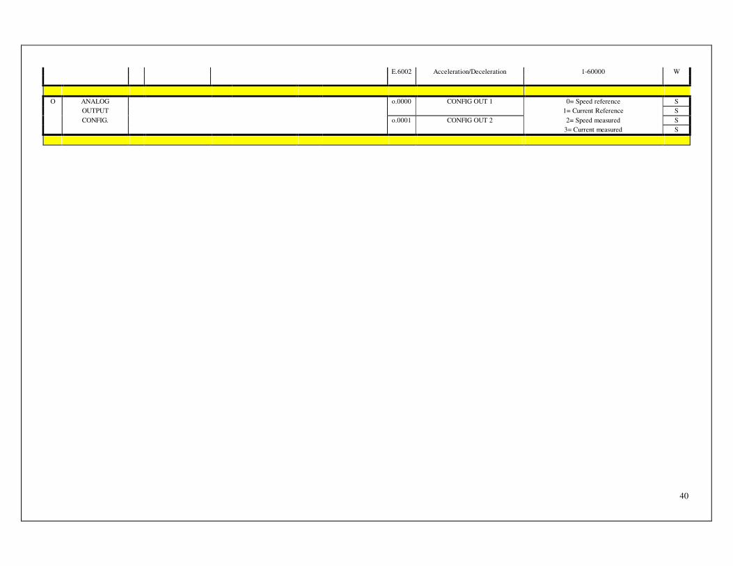
40
E.6002 Acceleration/Deceleration 1-60000 W
O ANALOG o.0000 CONFIG OUT 1 0= Speed reference S
OUTPUT 1= Current Reference S
CONFIG. o.0001 CONFIG OUT 2 2= Speed measured S
3= Current measured S

41
M1 DESCRIPTION M2 DESCRIPTION M3 DESCRIPTION M4 DESCRIPTION PAR. DESCRIPTION RANGE OF VALUES TYPE
i.0 PIN 25 DI J5 Enable
i.0000 Enable input choice on the front or
on the level
Edge / Level S
i.1 PIN 40 DI J5 Limit switch CW i.1000 Enable/Disable On / Off S
i.1001 Limit switch Contact Type 0= NC; 24=NO S
i.2 PIN 11 DI J5 Limit switch CCW i.2000 Enable/Disable On / Off S
I DIGITAL i.2001 Limit switch Contact Type 0= NC; 24=NO S
INPUT i.3 PIN 26 DI J5 Emergency i.3000 Enable/Disable On / Off S
i.4 PIN 41 DI J5 Reset i.4000 Enable/Disable On / Off S
i.5 PIN 12 DI J5 Run i.5000 Enable/Disable On / Off S
i.6 PIN 27 DI J5 Choose speed i.6000 Enable/Disable On / Off S
i.7 PIN 42 DI J5 Choose/reverse speed i.7000 Enable/Disable On / Off S
i.8 PIN17 e PIN32 Attiva JOG i.8000 Enable/Disable On / Off S
S.1 CONSTANT S.10 PID OF SPEED S.1000 KP Speed 0 - 3000 W
PID S.1001 KI Speed 0 - 3000 W
S.1002 KD Speed 0 - 3000 W
S.11 PID OF CURRENT S.1100 KP Current 0 - 3000 W
IN BRUSHLESS S.1101 KI Current 0 - 3000 W
MOTOR S.1102 KD Current 0 - 3000 W
S.1 CONSTANT
PID
S.14 PID POSITION S.1400 KP Position 0 - 4000 W
S.15 ERROR S.1500 Type following error 0= Warning; 1 = Alarm S
S SET UP POSITION S.1501 Threshold following error 0,0 - 179,0 ° S
S.16 Choice of Speed ref
in posit. Control JOG
S.1600 Choice of speed ref in control
position in manual mode (jog)
JOG =Rif.Vel.U.1300
AnL=Ref.speed analog. Pin1-16
S
AVANZATO S.2 SONDE HALL S.2000 Initial Autotiming On / Off S
S.2001 Calibrate Offset On / Off S
S.3 ENCODER S.3000 Simulated Encoder Resolution 256;1024;4096;16384 S
RESOLUTION S.3001 Default Data Load On / Off S
AND ALARMS S.3002 Reset Alarm On / Off W
S.3003 Alarm memory List of alarms occurred R
S.3004 Software Release Software release R
S.3005 Reverse Feedback direction On / Off S
S.4000 Max Voltage alarm Off= stored S
S.4001 Min voltage alarm On= automatic reset S
42
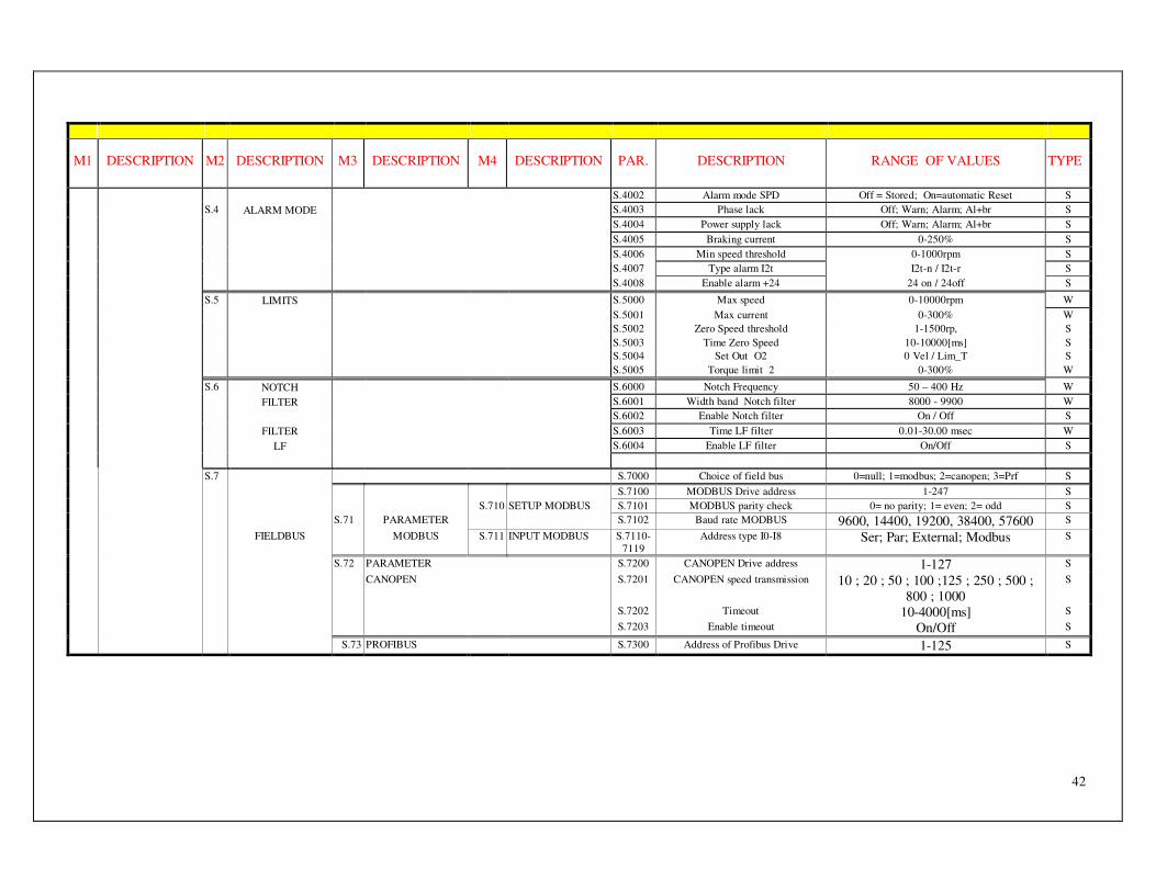
M1 DESCRIPTION M2 DESCRIPTION M3 DESCRIPTION M4 DESCRIPTION PAR. DESCRIPTION RANGE OF VALUES TYPE
S.4002 Alarm mode SPD Off = Stored; On=automatic Reset S
S.4 ALARM MODE S.4003 Phase lack Off; Warn; Alarm; Al+br S
S.4004 Power supply lack Off; Warn; Alarm; Al+br S
S.4005 Braking current 0-250% S
S.4006 Min speed threshold 0-1000rpm S
S.4007 Type alarm I2t I2t-n / I2t-r S
S.4008 Enable alarm +24 24 on / 24off S
S.5 LIMITS S.5000 Max speed 0-10000rpm W
S.5001 Max current 0-300% W
S.5002 Zero Speed threshold 1-1500rp, S
S.5003 Time Zero Speed 10-10000[ms] S
S.5004 Set Out O2 0 Vel / Lim_T S
S.5005 Torque limit 2 0-300% W
S.6 NOTCH S.6000 Notch Frequency 50 – 400 Hz W
FILTER S.6001 Width band Notch filter 8000 - 9900 W
S.6002 Enable Notch filter On / Off S
FILTER S.6003 Time LF filter 0.01-30.00 msec W
LF S.6004 Enable LF filter On/Off S
S.7 S.7000 Choice of field bus 0=null; 1=modbus; 2=canopen; 3=Prf S
S.7100 MODBUS Drive address 1-247 S
S.710 SETUP MODBUS S.7101 MODBUS parity check 0= no parity; 1= even; 2= odd S
S.71 PARAMETER S.7102 Baud rate MODBUS 9600, 14400, 19200, 38400, 57600 S
FIELDBUS MODBUS S.711 INPUT MODBUS S.7110-
7119
Address type I0-I8 Ser; Par; External; Modbus S
S.72 PARAMETER S.7200 CANOPEN Drive address 1-127 S
CANOPEN S.7201 CANOPEN speed transmission 10 ; 20 ; 50 ; 100 ;125 ; 250 ; 500 ;
800 ; 1000
S
S.7202 Timeout 10-4000[ms] S
S.7203 Enable timeout On/Off S
S.73 PROFIBUS S.7300 Address of Profibus Drive 1-125 S

43
H MENU’ AVAILABLE ONLY ENTERING A PASSWORD
H.0 Password H.0000 Password S
H.1 DRIVE SIZE H.1000 Drive current size 1,3/2,6 ; 1,5/2,6 ; 2,5/5 ; 3/6 ; 4/8 ; 6/12 ; 10/20 ;
11/22 ; 20/40 ; 35/70 ; 45/90; 75/150
H.1001 Drive voltage size 230; 460 S
H.1002 Time I2t 0,1-25,0 sec S
H.1003 Power loss alarm On / Off S
H.2000 High current 0-200,00A S
H.2001 Low current 0-200,00A S
H.2 TEST DRIVE H.2002 Time high current 1-1000sec S
H.2003 Time low current 1-1000sec S
H.2004 Test enable On / Off S
H RESERVED H.3000 DC Bus braking threshold S
AREA H.3001 Hysteresis for H.3000 S
ATIVA H.3 VOLTAGE H.3002 Max threshold DC BUS for alarm S
THRESHOLD H.3003 Hysteresis for H.3002 S
H.3004 Min threshold DC Bus for alarm S
H.3005 Hysteresis for H.3004 S
H.4 FREQ. LIMIT I2T H.4000 Freq.Limit threshold for I2t S
H.5 DELETE H.5000 Delete alarm stored S
ALLARMS
H.6 RESISTENZA H.6000 Valore in Ohm 10- 1000 Ohm S
FRENATURA H.6001 Potenza in Watt 30-3000 W S
H.6002 Tempo sovraccarico 1-255 sec S
Note 1 : The choice of the type of control can be modified only with drive in stop. Note 2: To enter in these menu push “Enter” and then “Esc” at the same time then release both and select again “Enter” Note 3 : To enter this menu a password is requested. Note 4 : The type of parameters can be: “R” = only read. “W” = Modifiable in all condition: Stop, Ena, Run. “E” = Modifiable in this condition: Stop, Ena. “S” = Modifiable in Stop condition.

45
7.2 Explanation of parameters
7.2.1 “D” menu : Display
Menu Description Parameter Description Range of values Type
d.0000 State of Drive EnA/Run/StoP R
d.0001 Speed 0-10000 rpm R
d.0002 Current 0-200,00 A R
d.0003 Dc Bus Voltage 0-1000 V R
d DISPLAY d.0004 Axes ratio -9,000-+9,000 R
d.0005 Position Rev 0-99999 rev R
d.0006 Position offset 0-32767 steps R
d.0007 Resolver Home Position 0-32767 steps R
d.0008 Current Size 1,5/2,6 – 75/150 R
d.0009 Voltage Size 240 / 460 R
Without alarms the display can shows the following selectable information: 0) State of the Driver: it shows the state of the drive:
Ena: The drive is enabled and motor is not running and in torque (Start command is not enabled).
Run: The drive is running (Enabled both command “Enable and Start”). Stop: The drive is not running. EMG: The drive is in emergency mode, . ( active if I3000=on; see table 1 cap.7.2.4)
1) Speed: it shows the real speed of the motor (in RPM) 2) Current: it shows the real current that the drive supply (in Ampere) 3) Voltage: It shows the DC Bus Voltage (in Volt) 4) Axis Ratio: It shows the speed ratio set between master axis and slave axis when Digital Lock is selected
(shown in relative number) 5) Rev position: It shows the absolute number of revolution done between the instantaneous motor position
and the home position (in rev number). 6) Offset position: It shows the absolute number of steps done between the instantaneous position of the
resolver and the Home Position. [shown in numbers of steps:1 step=(360/32768) degrees] 7) Resolver Home position: It shows the angular absolute position of the resolver when position goes out
from Home Position Sensor [shown in number of steps where a step is =(360/32768) degrees]. 8) Current Size: It shows the size of the drive as follows:
DGM240 DGM460 Value in
d.008 Rated
Current(A) Peak
Current (A) Value in
d.008 Rated
Current(A) Peak
Current (A) 1,5-2,6 1,5 2,6 1,3-2,6 1,3 2,6 3,0-6,0 3,0 6,0 2,5-5.0 2,5 5,0 4,0-8,0 4,0 8,0 6.0-12.0 6,0 12,0 10-20 10,0 20,0 11-22 10,0 20,0
20-40 20,0 40,0 35-70 35,0 70,0 45-90 45,0 90,0 75-150 70,0 140,0
9) Voltage Size: It shows the voltage size of the drive:230VAC or 460VAC.
46
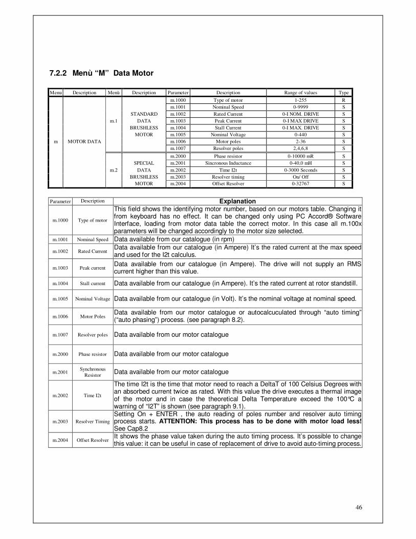
7.2.2 Menù “M” Data Motor Menu Description Menù Description Parameter Description Range of values Type
m.1000 Type of motor 1-255 R
m.1001 Nominal Speed 0-9999 S
STANDARD m.1002 Rated Current 0-I NOM. DRIVE S
m.1 DATA m.1003 Peak Current 0-I MAX DRIVE S
BRUSHLESS m.1004 Stall Current 0-I MAX. DRIVE S
MOTOR m.1005 Nominal Voltage 0-440 S
m MOTOR DATA m.1006 Motor poles 2-36 S
m.1007 Resolver poles 2,4,6,8 S
m.2000 Phase resistor 0-10000 mR S
SPECIAL m.2001 Sincronous Inductance 0-40,0 mH S
m.2 DATA m.2002 Time I2t 0-3000 Seconds S
BRUSHLESS m.2003 Resolver timing On/ Off S
MOTOR m.2004 Offset Resolver 0-32767 S
Parameter Description Explanation
m.1000 Type of motor
This field shows the identifying motor number, based on our motors table. Changing it from keyboard has no effect. It can be changed only using PC Accord® Software Interface, loading from motor data table the correct motor. In this case all m.100x parameters will be changed accordingly to the motor size selected.
m.1001 Nominal Speed Data available from our catalogue (in rpm)
m.1002 Rated Current Data available from our catalogue (in Ampere) It’s the rated current at the max speed and used for the I2t calculus.
m.1003 Peak current Data available from our catalogue (in Ampere). The drive will not supply an RMS current higher than this value.
m.1004 Stall current Data available from our catalogue (in Ampere). It’s the rated current at rotor standstill.
m.1005 Nominal Voltage Data available from our catalogue (in Volt). It’s the nominal voltage at nominal speed.
m.1006 Motor Poles Data available from our motor catalogue or autocalcuculated through “auto timing” (“auto phasing”) process. (see paragraph 8.2).
m.1007 Resolver poles Data available from our motor catalogue
m.2000 Phase resistor Data available from our motor catalogue
m.2001 Synchronous
Resistor Data available from our motor catalogue
m.2002 Time I2t
The time I2t is the time that motor need to reach a DeltaT of 100 Celsius Degrees with an absorbed current twice as rated. With this value the drive executes a thermal image of the motor and in case the theoretical Delta Temperature exceed the 100°C a warning of “I2T” is shown (see paragraph 9.1).
m.2003 Resolver Timing
Setting On + ENTER , the auto reading of poles number and resolver auto timing process starts. ATTENTION: This process has to be done with motor load less! See Cap8.2
m.2004 Offset Resolver It shows the phase value taken during the auto timing process. It’s possible to change this value: it can be useful in case of replacement of drive to avoid auto-timing process.
47
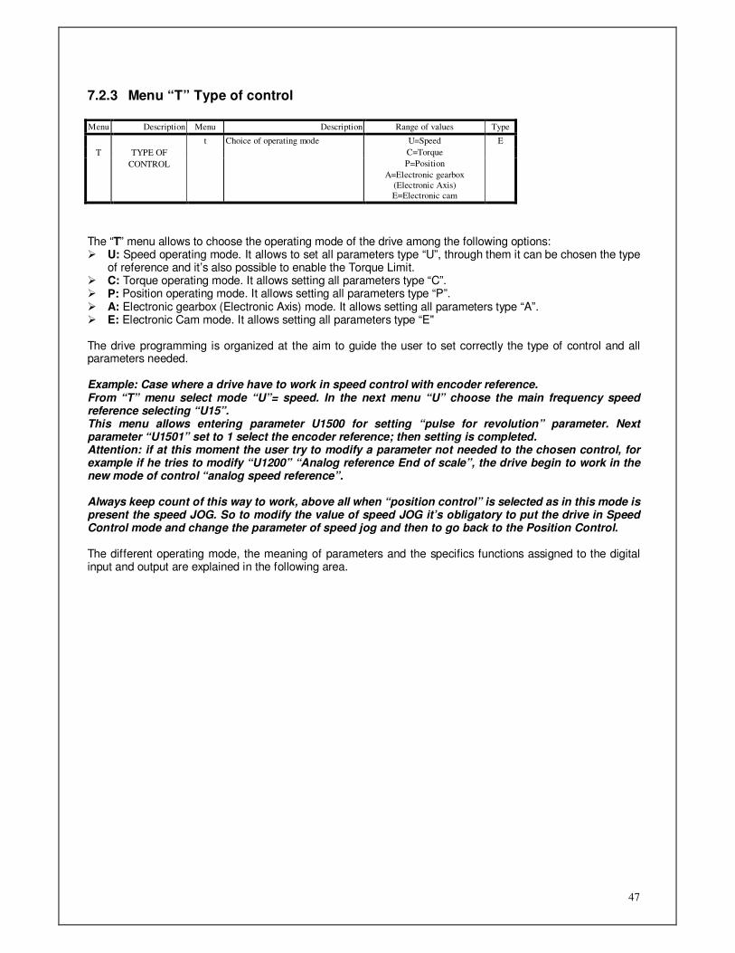
7.2.3 Menu “T” Type of control Menu Description Menu Description Range of values Type
t Choice of operating mode U=Speed E
T TYPE OF C=Torque
CONTROL P=Position
A=Electronic gearbox
(Electronic Axis)
E=Electronic cam
The “T” menu allows to choose the operating mode of the drive among the following options: U: Speed operating mode. It allows to set all parameters type “U”, through them it can be chosen the type
of reference and it’s also possible to enable the Torque Limit. C: Torque operating mode. It allows setting all parameters type “C”. P: Position operating mode. It allows setting all parameters type “P”. A: Electronic gearbox (Electronic Axis) mode. It allows setting all parameters type “A”. E: Electronic Cam mode. It allows setting all parameters type “E" The drive programming is organized at the aim to guide the user to set correctly the type of control and all parameters needed. Example: Case where a drive have to work in speed control with encoder reference. From “T” menu select mode “U”= speed. In the next menu “U” choose the main frequency speed reference selecting “U15”. This menu allows entering parameter U1500 for setting “pulse for revolution” parameter. Next parameter “U1501” set to 1 select the encoder reference; then setting is completed. Attention: if at this moment the user try to modify a parameter not needed to the chosen control, for example if he tries to modify “U1200” “Analog reference End of scale”, the drive begin to work in the new mode of control “analog speed reference”. Always keep count of this way to work, above all when “position control” is selected as in this mode is present the speed JOG. So to modify the value of speed JOG it’s obligatory to put the drive in Speed Control mode and change the parameter of speed jog and then to go back to the Position Control. The different operating mode, the meaning of parameters and the specifics functions assigned to the digital input and output are explained in the following area.

48
7.2.4 Menu “U” Speed Control Type Menu Description Menu Description Menu Description Parameter Description Range of values Type
U.10 REF.CHOICE U.1000 Choice of main speed ref. 1-AnL / 2-Int / 3—jog /
4-mot / 5-FrE
S
U.11 ANALOG U.1100 End of Scale Analog Ref. 0÷10000 rpm W
REFERENCE U.1101 Analog Ref. Offset -999,9 ÷ +999,9rpm W
U.1102 LF filter 0-10,00 seconds W
U.1103 Reference Reverse On/Off S
U.12 INTERNAL U.1200 Internal Speed 1 0÷+-10000 rpm W
REFERENCE U.1201 Internal Speed 2 0÷+-10000 rpm W
U.1202 Internal Speed 3 0÷+-10000 rpm W
U.1 MAIN U.1203 Internal Speed 4 0÷+-10000 rpm W
SPEED U.13 JOG U.1300 Speed Jog 0÷10000 rpm S
SPEED REFERENCE U.1301 Jog Mode 0=keyboard / 1=external S
U MODE U.14 ELECTRONIC
POTENTIOMETER U.1400 Max speed 0÷10000 rpm
S
U.15 FREQUENCY U.1500 Pulse per revolution 0÷10000 S
(Note 1) REFERENCE U.1501 Frequency mode 0= encoder / 1= f./Dir. S
U.21 ANALOG U.2100 End of Scale Analog Aux
Ref.
0÷10000 rpm W
REFERENCE U.2101 Offset Analog Aux Ref. -3200,0 ÷ +3200,0rpm W
U.2 AUX U.22 INTERNAL U.2200 Internal Aux Speed 0÷10000 rpm W
REFERENCE U.23 TORQUE U.2300 End of Scale Torque Limit 0÷250% W
LIMIT U.2301 Offset Torque Limit 0÷+-100% W
U.24 ENABLE U.2400 Aux Ref. Enable Off / On S
U.3000 Acceleration CW 1 ÷ 60000 r/min x sec W
U.3001 Deceleration CW 1 ÷ 60000 r/min x sec W
U.3002 Acceleration CCW 1 ÷ 60000 r/min x sec W
U3 RAMPS U.3003 Deceleration CCW 1 ÷ 60000 r/min x sec W
U.3004 Jerk rounding off 1 ÷ 60000 r/min x sec² W
U.3005 Enable S Ramp On / Off S
U.3006 Enable Ramp On / Off S
U.4 U.4000 Emergency mode selection 1-MAS/2-COP/3-
DEC/4-TEM
S
EMERGENCY U.4001 Torque limit 1 ÷ 300% S
MODE U.4002 Deceleration 1 ÷60000 rpm/s S
U.4003 Ramp Time 50 ÷10000 ms
( default=500ms)
S
U.5 REVERSE SPEED REFERENCE
U.5000 Reversed speed reference Off / On S
Note 1) The choice of the type of control can be done or in Stop or in Enable; It’s not allowed to change the type of control in Run condition.
Parameter Description Explanation
U.1000 Choice of min
speed reference
Set the source of speed reference for speed control operation. The possible choices are:
1. AnL = the drive consider as speed reference the voltage present at PIN1 and 16 of connector J5
2. InT = the drive considere as speed reference the value set in parameter from U.1200 to U.1203
3. JOG = the drive consider as speed reference the value set at parameter U.1300
4. MOT = the drive consider as speed reference an internal value changeable through two inputs useda to “increase” and “decrease” the value.
5. FrE = the drive consider this selection as speed reference the frequency of a line drive that enters on PIN23 and 38 of connector J5, shile the direction is provided by the signal that enters on PIN8 and 37 of J5. The reference can be generated by the two channels of an encoder or by frequency signal with a further logic signal direction. See paragraph 5.5

49
for wiring.

50
(U11) Analog main speed reference
Once made this selection, the drive uses as speed reference the Voltage present in pin1 and pin16 of connector J5. All the other main references are not considered by the drive in this case. With positive reference on pin 16 , ATIVA motors turns in CW direction.
Parameter Description Explanation
U.1100 End of Scale
Analog Ref.
Set the speed in rpm that correspond to the 10V reference. In case the max speed ref. Is lower of 10Volt, set the result of the following formula.
End of scale = [Speedmax(rpm) : Spedrefmax(Volt)]∗10 For example if max reference is 7,5 Volt correspond a max speed of 3000 rpm I have to set a End of scale of 4000.
U.1101 Analog Ref. Offset Set in rpm with a resolution at tenth, to compensate the speed offset.
U.1102 LF filter
Set in seconds, with a centesimal of second resolution, a time constant for a RC Digital filter applied to a speed reference. A different setting from Zero of this parameter can filter possible noises but put a delay in the answer at a variation of the analog reference.
TABLE 1 Digital Inputs working in speed mode with analgical and frequency reference.
Input N° Pin of J5 Name Function
I0 25 Power on/off Enable power to the motor. In case of absence of command on pin12 the motor remain still in torque. The display shows message “Ena” in menu “d.0000”.
I1 40 Limit switch CW Input for CW limit switch. When enabled (I.1000=on) if the motor running in CW direction will touch the limit switch sensor the motor will be stopped without ramp and will remain still in torque. See capt. 7.2.10
I2 11 Limit switch CCW Input for CCW limit switch. When enabled (I.2000=on) if the motor running in CCW direction will touch the limit switch sensor the motor will be stopped without ramp and will remain still in torque. See cap. 7.2.10
I3 26 Stop Emergency Input for Emergency stop command. When enables (I.3000=on) in case of absence of this input the motor will be stopped without ramp and will remain still in torque. See cap. 7.2.10
I4 41 Reset Alarms Reset alarms. When enabled (I.4000=On) it reset all alarms except FA 03. Attention: in case of resetting while the external run is
still active, there is the risk that the motor starts suddenly.
I5 12 Start/Stop Enable the speed reference. With this signal the motor follows the setting of the speed reference with its ramps. Removing this signal the motor will stop with set ramp. The display will show the message “Run” in menu “d.0000 ”.
I6 27 Disabled No functions
I7 42 Reference Reverse When enabled (I.7000=on) activating this input the speed reference reverse and also direction of the motor revolution.
I8 Disabled No functions
I9 2 Enable Torque limit 2
To use this pin as a digital input to 24V, connect pin 31 of J5 to GND of digital inputs. With the input open the motor current limit is set by parameter S.5000. With the input at +24V the motor current is limited by the parameter S.5005 (torque limit 2)
Note: To enable the inputs and set the type of contact of limit switch refer to cap. 7.2.10 (U12) Internal main reference
Once made this selection, the drive use as speed reference the value presents in parameters U.1200 a U.1203. All the other main references are not considered by the drive in this case. With positive reference, ATIVA motors turns in CW direction.
51
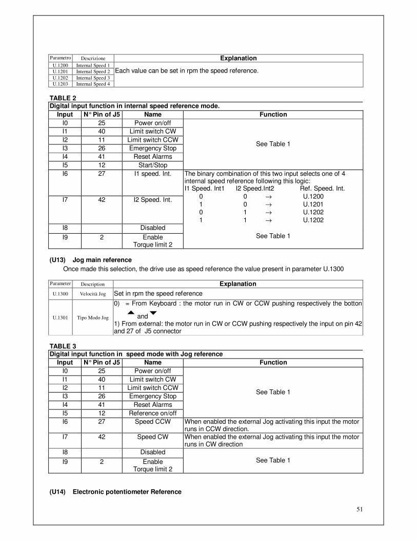
Parametro Descrizione Explanation U.1200 Internal Speed 1
U.1201 Internal Speed 2
U.1202 Internal Speed 3
U.1203 Internal Speed 4
Each value can be set in rpm the speed reference.
TABLE 2 Digital input function in internal speed reference mode.
Input N° Pin of J5 Name Function
I0 25 Power on/off
I1 40 Limit switch CW
I2 11 Limit switch CCW
I3 26 Emergency Stop
I4 41 Reset Alarms
I5 12 Start/Stop
See Table 1
I6 27 I1 speed. Int.
I7 42 I2 Speed. Int.
The binary combination of this two input selects one of 4 internal speed reference following this logic: I1 Speed. Int1 I2 Speed.Int2 Ref. Speed. Int.
0 0 → U.1200
1 0 → U.1201
0 1 → U.1202
1 1 → U.1202 I8 Disabled
I9 2 Enable Torque limit 2
See Table 1
(U13) Jog main reference
Once made this selection, the drive use as speed reference the value present in parameter U.1300
Parameter Description Explanation
U.1300 Velocità Jog Set in rpm the speed reference
U.1301 Tipo Modo Jog
0) = From Keyboard : the motor run in CW or CCW pushing respectively the botton
tandu 1) From external: the motor run in CW or CCW pushing respectively the input on pin 42 and 27 of J5 connector
TABLE 3 Digital input function in speed mode with Jog reference
Input N° Pin of J5 Name Function
I0 25 Power on/off
I1 40 Limit switch CW
I2 11 Limit switch CCW
I3 26 Emergency Stop
I4 41 Reset Alarms
I5 12 Reference on/off
See Table 1
I6 27 Speed CCW When enabled the external Jog activating this input the motor runs in CCW direction.
I7 42 Speed CW When enabled the external Jog activating this input the motor runs in CW direction
I8 Disabled
I9 2 Enable Torque limit 2
See Table 1
(U14) Electronic potentiometer Reference

52
Once made this selection, the drive use as speed reference an internal value changeable using two inputs that work as “increase” and “decrease”. The variation of the reference is made whit a ramp which inclination is due to the acceleration and deceleration values set in parameter of ramps “r”. Switching on the drive the reference is reset to zero. Successively it remains stored at the last value set by inputs “Increase”-“decrease”. It’s provided an input to reset the active reference only when drive is in stop condition. With the button up it’s possible to increase the value of the reference till the value set in parameter U.1400. With the button down it is possible to decrease the value of the reference till the value ZERO. To reverse the rotation direction it need to work on the input “reverse rotation”.
Parameter Description Explanation
U.1400 Max Speed Set the limit for the max speed reachable with the button up “increase”.
TABLE 4 Digital input function in speed mode with reference from electronic potentiometer.
Input N. Pin of J5 Name Function
I0 25 Power on/off See Table 1
I1 40 Increase Input for “increase” CW e CCW
I2 11 Decrease Input for ”decrease” CW e CCW
I3 26 Stop Emergency See table 1
I4 41 Reset Alarms See table 1
I5 12 Start/Stop See table 1
I6 27 Reset ref. Reset internal value of electronic potentiometer without ramp. Active only in stop condition.
I7 42 Reference Reverse Reverse the rotation direction of the motor
I8 Disabled
I9 2 Enable Torque limit 2
See Table 1
(U15) Main Frequency Reference
Once made this selection, the drive use as speed reference the frequency of the Line Driver signal present in pin8 and pin37 of connector J5. All the other main reference is not considered by the drive in this case. The reference can be generated by two encoder channels or by a frequency signal with a further logic signal of direction.
Parameter Description Explanation
U.1500 Pulses for rotation
Set the number of pulses of the signal wanted for a complete revolution of the motor shaft. Lower values set in this field can generate an irregular rotation of the motor especially at low speed. We suggest to use values near or bigger than 1024.The frequency related to the max speed can be calculated from the following formula:
fmax(Hz)= pulses for rev∗speed.max(rpm)/60 fmax have not to be bigger than 500KHz. In case the ref came from the simulated encoder of another DGM (master) the value to set, for the same speed, must be of same resolution of the simulated encoder of the drive master. To rotate the motor shaft at a doubled or middle speed compared to the Master set a value of half or double compared to the simulated encoder of the master.
U.1501 Frequency mode
Select the type of signal used for the reference in frequency. Select “0 “ when you use two signals in quadrature of a simulated or a real encoder. Select “1” when you use a signal in frequency and one for direction
For the function of digital input refer to TABLE 1
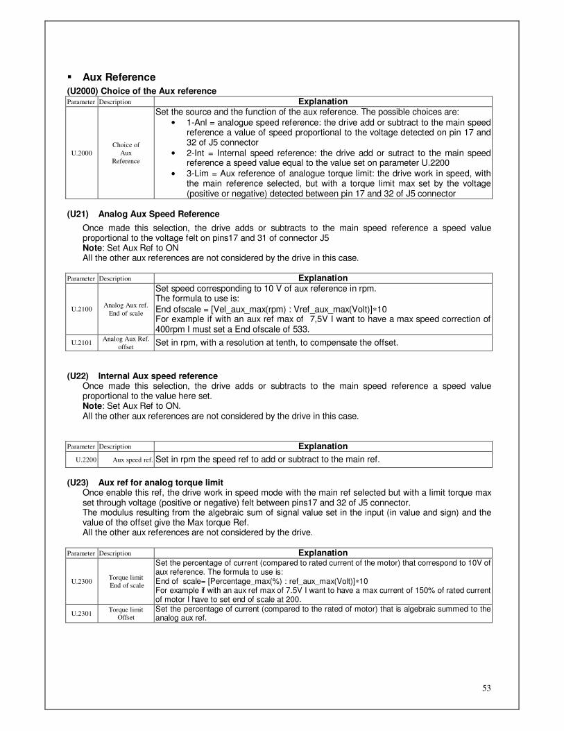
53
Aux Reference
(U2000) Choice of the Aux reference Parameter Description Explanation
U.2000
Choice of
Aux
Reference
Set the source and the function of the aux reference. The possible choices are:
• 1-Anl = analogue speed reference: the drive add or subtract to the main speed reference a value of speed proportional to the voltage detected on pin 17 and 32 of J5 connector
• 2-Int = Internal speed reference: the drive add or sutract to the main speed reference a speed value equal to the value set on parameter U.2200
• 3-Lim = Aux reference of analogue torque limit: the drive work in speed, with the main reference selected, but with a torque limit max set by the voltage (positive or negative) detected between pin 17 and 32 of J5 connector
(U21) Analog Aux Speed Reference
Once made this selection, the drive adds or subtracts to the main speed reference a speed value proportional to the voltage felt on pins17 and 31 of connector J5 Note: Set Aux Ref to ON All the other aux references are not considered by the drive in this case.
Parameter Description Explanation
U.2100 Analog Aux ref.
End of scale
Set speed corresponding to 10 V of aux reference in rpm. The formula to use is:
End ofscale = [Vel_aux_max(rpm) : Vref_aux_max(Volt)]∗10 For example if with an aux ref max of 7,5V I want to have a max speed correction of 400rpm I must set a End ofscale of 533.
U.2101 Analog Aux Ref.
offset Set in rpm, with a resolution at tenth, to compensate the offset.
(U22) Internal Aux speed reference
Once made this selection, the drive adds or subtracts to the main speed reference a speed value proportional to the value here set. Note: Set Aux Ref to ON. All the other aux references are not considered by the drive in this case.
Parameter Description Explanation
U.2200 Aux speed ref. Set in rpm the speed ref to add or subtract to the main ref.
(U23) Aux ref for analog torque limit
Once enable this ref, the drive work in speed mode with the main ref selected but with a limit torque max set through voltage (positive or negative) felt between pins17 and 32 of J5 connector. The modulus resulting from the algebraic sum of signal value set in the input (in value and sign) and the value of the offset give the Max torque Ref. All the other aux references are not considered by the drive.
Parameter Description Explanation
U.2300 Torque limit
End of scale
Set the percentage of current (compared to rated current of the motor) that correspond to 10V of aux reference. The formula to use is: End of scale= [Percentage_max(%) : ref_aux_max(Volt)]∗10 For example if with an aux ref max of 7.5V I want to have a max current of 150% of rated current of motor I have to set end of scale at 200.
U.2301 Torque limit
Offset
Set the percentage of current (compared to the rated of motor) that is algebraic summed to the analog aux ref.
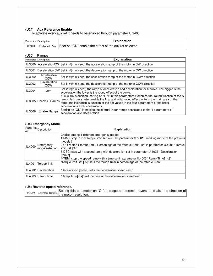
54
(U24) Aux Reference Enable
To activate every aux ref it needs to be enabled through parameter U.2400
Parameter Description Explanation
U.2400 Enable ref. Aux If set on “ON” enable the effect of the aux ref selected.
(U30) Ramps Parameter Description Explanation
U.3000 AccelerationCW Set in r/(min x sec) the acceleration ramp of the motor in CW direction
U.3001 Deceleration CW Set in r/(min x sec) the deceleration ramp of the motor in CW direction
U.3002 Acceleration
CCW Set in r/(min x sec) the acceleration ramp of the motor in CCW direction
U.3003 Deceleration
CCW Set in r/(min x sec) the deceleration ramp of the motor in CCW direction
U.3004 Jerk Set in r/(min x sec²) the ramp of acceleration and deceleration for S curve. The bigger is the acceleration the lower is the round effect of the curve.
U.3005 Enable S Ramps
If U.3006 is enabled, setting on “ON” in this parameters it enables the round function of the S ramp. Jerk parameter enable the final and initial round effect while in the main area of the ramp, the inclination is function of the set values in the four parameters of the linear accelerations and decelerations.
U.3006 Enable Ramps Setting on “ON” it enables the internal linear ramps associated to the 4 parameters of acceleration and deceleration.
(U4) Emergency Mode Parameter
Description Explanation
U.4000 Emergency mode selection
Choice among 4 different emergency mode: 1-MAS: stop in max torque limit set from the parameter S.5001 ( working mode of the previous models ) 2-COP: stop il torque limit ( Percentage of the rated current ) set in parameter U.4001 “Torque limit Set [%]” 3-DEC: stop with a speed ramp with deceleration set in parameter U.4002 “Deceleration [rpm/s] 4-TEM: stop the speed ramp with a time set in parameter U.4003 “Ramp Time[ms]”
U.4001 Torque limit “Torque limit Set [%]” sets the toruqe limiti in percentage of the rated current
U.4002 Deceleration “Deceleration [rpm/s] sets the deceleration speed ramp
U.4003 Ramp Time “Ramp Time[ms]” set the time of the deceleration speed ramp
(U5) Reverse speed reference.
U.5000 Reference Reverse Setting this parameter on “On”, the speed reference reverse and also the direction of the motor revolution.
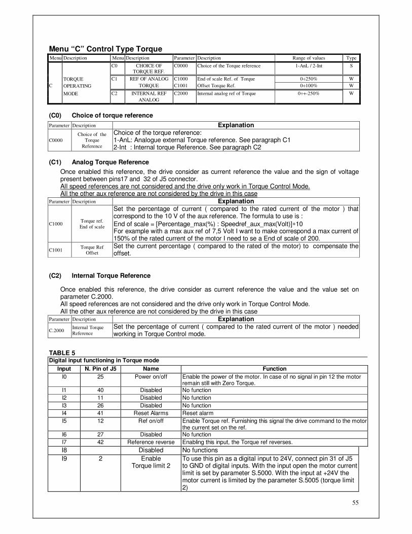
55
Menu “C” Control Type Torque Menu Description Menu Description Parameter Description Range of values Type
C0 CHOICE OF
TORQUE REF.
C0000 Choice of the Torque reference 1-AnL / 2-Int S
TORQUE C1 REF OF ANALOG C1000 End of scale Ref. of Torque 0÷250% W
C OPERATING TORQUE C1001 Offset Torque Ref. 0÷100% W
MODE C2 INTERNAL REF C2000 Internal analog ref of Torque 0÷+-250% W
ANALOG
(C0) Choice of torque reference
Parameter Description Explanation
C0000
Choice of the
Torque
Reference
Choice of the torque reference: 1-AnL: Analogue external Torque reference. See paragraph C1 2-Int : Internal torque Reference. See paragraph C2
(C1) Analog Torque Reference
Once enabled this reference, the drive consider as current reference the value and the sign of voltage present between pins17 and 32 of J5 connector. All speed references are not considered and the drive only work in Torque Control Mode. All the other aux reference are not considered by the drive in this case
Parameter Description Explanation
C1000 Torque ref.
End of scale
Set the percentage of current ( compared to the rated current of the motor ) that correspond to the 10 V of the aux reference. The formula to use is :
End of scale = [Percentage_max(%) : Speedref_aux_max(Volt)]∗10 For example with a max aux ref of 7,5 Volt I want to make correspond a max current of 150% of the rated current of the motor I need to se a End of scale of 200.
C1001 Torque Ref
Offset
Set the current percentage ( compared to the rated of the motor) to compensate the offset.
(C2) Internal Torque Reference
Once enabled this reference, the drive consider as current reference the value and the value set on parameter C.2000. All speed references are not considered and the drive only work in Torque Control Mode. All the other aux reference are not considered by the drive in this case
Parameter Description Explanation
C.2000 Internal Torque
Reference
Set the percentage of current ( compared to the rated current of the motor ) needed working in Torque Control mode.
TABLE 5 Digital input functioning in Torque mode
Input N. Pin of J5 Name Function
I0 25 Power on/off Enable the power of the motor. In case of no signal in pin 12 the motor remain still with Zero Torque.
I1 40 Disabled No function
I2 11 Disabled No function
I3 26 Disabled No function
I4 41 Reset Alarms Reset alarm
I5 12 Ref on/off Enable Torque ref. Furnishing this signal the drive command to the motor the current set on the ref.
I6 27 Disabled No function
I7 42 Reference reverse Enabling this input, the Torque ref reverses.
I8 Disabled No functions
I9 2 Enable Torque limit 2
To use this pin as a digital input to 24V, connect pin 31 of J5 to GND of digital inputs. With the input open the motor current limit is set by parameter S.5000. With the input at +24V the motor current is limited by the parameter S.5005 (torque limit 2)
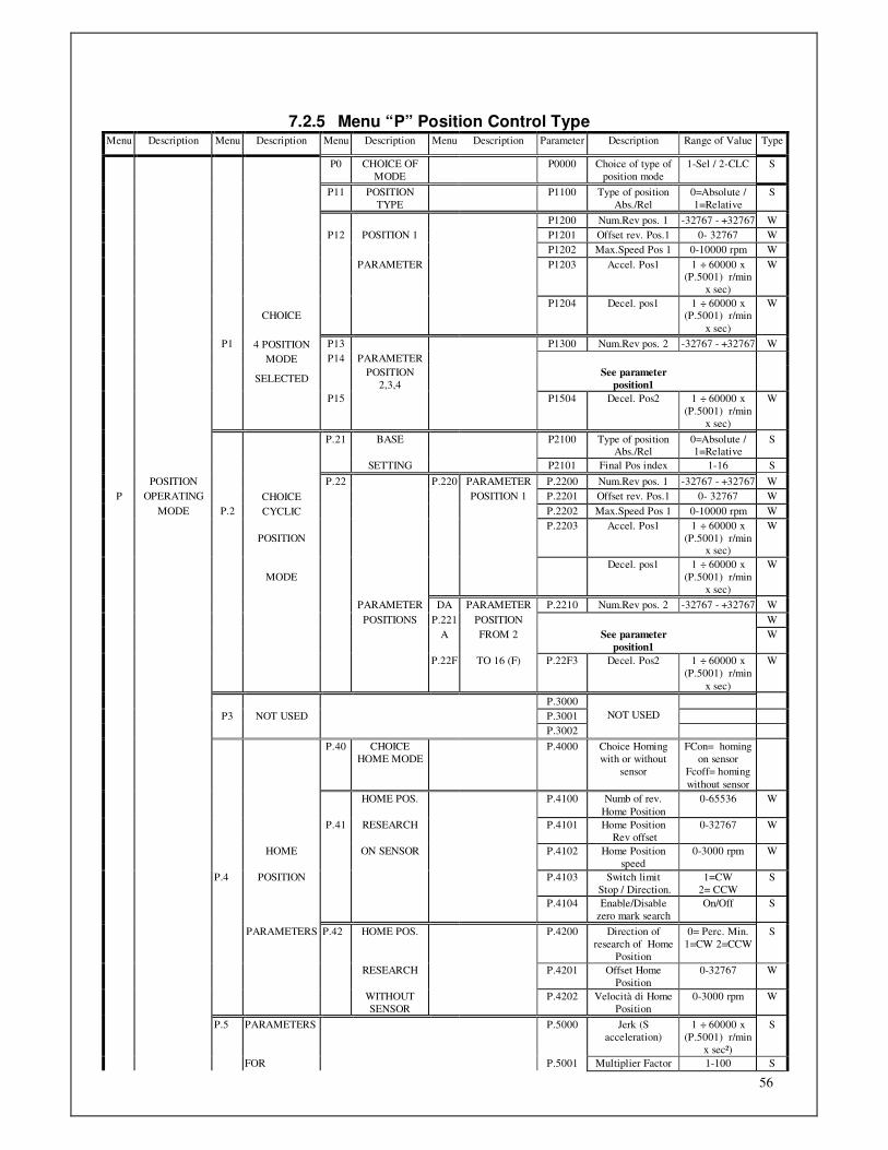
56
7.2.5 Menu “P” Position Control Type Menu Description Menu Description Menu Description Menu Description Parameter Description Range of Value Type
P0 CHOICE OF
MODE
P0000 Choice of type of
position mode
1-Sel / 2-CLC S
P11 POSITION
TYPE
P1100 Type of position
Abs./Rel
0=Absolute /
1=Relative
S
P1200 Num.Rev pos. 1 -32767 - +32767 W
P12 POSITION 1 P1201 Offset rev. Pos.1 0- 32767 W
P1202 Max.Speed Pos 1 0-10000 rpm W
PARAMETER P1203 Accel. Pos1 1 ÷ 60000 x (P.5001) r/min
x sec)
W
CHOICE
P1204 Decel. pos1 1 ÷ 60000 x (P.5001) r/min
x sec)
W
P1 4 POSITION P13 P1300 Num.Rev pos. 2 -32767 - +32767 W
MODE P14 PARAMETER
SELECTED
POSITION
2,3,4
See parameter
position1
P15 P1504 Decel. Pos2 1 ÷ 60000 x
(P.5001) r/min
x sec)
W
P.21 BASE P2100 Type of position Abs./Rel
0=Absolute / 1=Relative
S
SETTING P2101 Final Pos index 1-16 S
POSITION P.22 P.220 PARAMETER P.2200 Num.Rev pos. 1 -32767 - +32767 W
P OPERATING CHOICE POSITION 1 P.2201 Offset rev. Pos.1 0- 32767 W
MODE P.2 CYCLIC P.2202 Max.Speed Pos 1 0-10000 rpm W
POSITION
P.2203 Accel. Pos1 1 ÷ 60000 x
(P.5001) r/min x sec)
W
MODE
Decel. pos1 1 ÷ 60000 x
(P.5001) r/min
x sec)
W
PARAMETER DA PARAMETER P.2210 Num.Rev pos. 2 -32767 - +32767 W
POSITIONS P.221 POSITION W
A FROM 2 See parameter
position1
W
P.22F TO 16 (F) P.22F3 Decel. Pos2 1 ÷ 60000 x
(P.5001) r/min
x sec)
W
P.3000
P3 NOT USED P.3001
P.3002
NOT USED
P.40 CHOICE
HOME MODE
P.4000 Choice Homing
with or without
sensor
FCon= homing
on sensor
Fcoff= homing
without sensor
HOME POS. P.4100 Numb of rev.
Home Position
0-65536 W
P.41 RESEARCH P.4101 Home Position
Rev offset
0-32767 W
HOME ON SENSOR P.4102 Home Position
speed
0-3000 rpm W
P.4 POSITION P.4103 Switch limit
Stop / Direction.
1=CW
2= CCW
S
P.4104 Enable/Disable
zero mark search
On/Off S
PARAMETERS P.42 HOME POS. P.4200 Direction of
research of Home
Position
0= Perc. Min.
1=CW 2=CCW
S
RESEARCH P.4201 Offset Home
Position
0-32767 W
WITHOUT
SENSOR
P.4202 Velocità di Home
Position
0-3000 rpm W
P.5 PARAMETERS P.5000 Jerk (S
acceleration)
1 ÷ 60000 x
(P.5001) r/min
x sec²)
S
FOR P.5001 Multiplier Factor 1-100 S
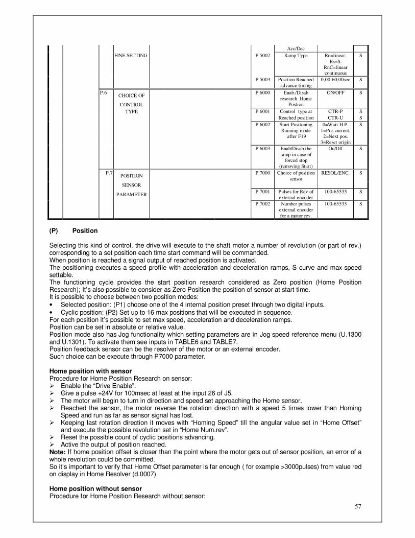
57
Acc/Dec
FINE SETTING P.5002 Ramp Type Rn=linear;
Rs=S.
RnC=linear continuous
S
P.5003 Position Reached
advance timing
0,00-60,00sec S
P.6 CHOICE OF
P.6000 Enab./Disab
research Home
ON/OFF S
CONTROL Postion
TYPE P.6001 Control type at CTR-P S
Reached position CTR-U S
P.6002 Start Positoning
Running mode
after F19
0=Wait H.P.
1=Pos current.
2=Next pos.
3=Reset origin
S
P.6003 Enab/Disab the
ramp in case of
forced stop
(removing Start)
On/Off S
P.7 POSITION
P.7000 Choice of position
sensor
RESOL/ENC. S
SENSOR
PARAMETER
P.7001 Pulses for Rev of
external encoder
100-65535 S
P.7002 Number pulses
external encoder
for a motor rev.
100-65535 S
(P) Position Selecting this kind of control, the drive will execute to the shaft motor a number of revolution (or part of rev.) corresponding to a set position each time start command will be commanded. When position is reached a signal output of reached position is activated. The positioning executes a speed profile with acceleration and deceleration ramps, S curve and max speed settable. The functioning cycle provides the start position research considered as Zero position (Home Position Research); It’s also possible to consider as Zero Position the position of sensor at start time. It is possible to choose between two position modes:
• Selected position: (P1) choose one of the 4 internal position preset through two digital inputs.
• Cyclic position: (P2) Set up to 16 max positions that will be executed in sequence. For each position it’s possible to set max speed, acceleration and deceleration ramps. Position can be set in absolute or relative value. Position mode also has Jog functionality which setting parameters are in Jog speed reference menu (U.1300 and U.1301). To activate them see inputs in TABLE6 and TABLE7. Position feedback sensor can be the resolver of the motor or an external encoder. Such choice can be execute through P7000 parameter. Home position with sensor Procedure for Home Position Research on sensor: Enable the “Drive Enable”. Give a pulse +24V for 100msec at least at the input 26 of J5. The motor will begin to turn in direction and speed set approaching the Home sensor. Reached the sensor, the motor reverse the rotation direction with a speed 5 times lower than Homing
Speed and run as far as sensor signal has lost. Keeping last rotation direction it moves with “Homing Speed” till the angular value set in “Home Offset”
and execute the possible revolution set in “Home Num.rev”. Reset the possible count of cyclic positions advancing. Active the output of position reached. Note: If home position offset is closer than the point where the motor gets out of sensor position, an error of a whole revolution could be committed. So it’s important to verify that Home Offset parameter is far enough ( for example >3000pulses) from value red on display in Home Resolver (d.0007) Home position without sensor Procedure for Home Position Research without sensor:

58
Enable the “Drive Enable”. Give a pulse +24V for 100msec at least at the input 26 of J5. The motor will begin to turn in direction and speed set approaching the angular position set. Reached this position the motor stop. Reset the possible count of cyclic positions advancing. Active the output of position reached. (P0) Control type Selected position Parameter Description Explanation
P.0000
Choice of
Positioner
Mode
1-Sel : this select the mode” Positioner with selected position”. See paragraph P1 2-CLC : this select the mode” Cyclic positions”. See paragraph P2
(P1) Control type Selected position Selecting this parameter you set a control of position mode with selected positions. Parameter Description Explanation
P1100 Position Type
Abs./Rel
Allows selecting the type of position between absolute or relative, unique for all 4 positions. 0 = Absolute: The values can be set as absolute posion.The Zero position is the one obtained at the end of Home position research. 1 = Relative: The values set will be dealt as values of position relative to the last positioning executed.
P.1200;
P.1300;
P.1400;
P.1500
Rev Numb
Position N
Set the number of rev. for the selected position. Ex. If I have to do 3,75 rev. In CW direction, I set 3 in this field and 24576 in the next field. If I have to do 3,75 rev in CWW direction I set–4 and 8192 (equivalent to 0,25 rev) in the next field.
P.1201;
P.1301;
P.1401;
P.1501
Offset rev. Pos.1
Set the fraction of rev of the selected position. Remember that a rev is 32768=360°. To set a CCW position set, in the revolutions field, a negative value equivalent to the number of revs increased of 1 and in this field the value corresponding to the angle to remove to the revolution added. See above example.
P.1202;
P.1302; P.1402;
P.1502
Max speed pos.N Set the max speed in rpm for each position.
P.1203; P.1303;
P.1403;
P.1503
Acceleration pos.N
Set the acceleration value for each position. This value of acceleration (expressed in rev/(min xsec.) is multiply for a factor set in parameter P.5001. This field is preset to 100.
P.1204;
P.1304;
P.1404; P.1504
Deceleration pos.N
Set the deceleration value for each position. This value of acceleration (expressed in rev/(min xsec.) is multiply for a factor set in parameter P.5001. This field is preset to 100.
NOTE See parameters P.5000, P.5001, e P.5002. as concern ramps
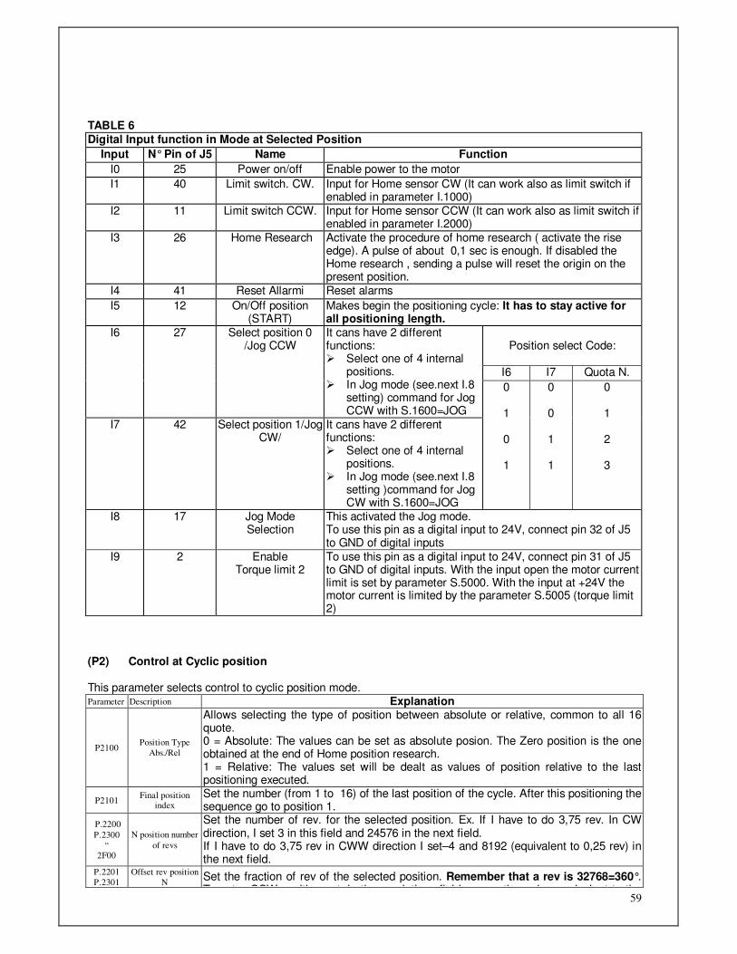
59
TABLE 6
Digital Input function in Mode at Selected Position
Input N° Pin of J5 Name Function
I0 25 Power on/off Enable power to the motor
I1 40 Limit switch. CW. Input for Home sensor CW (It can work also as limit switch if enabled in parameter I.1000)
I2 11 Limit switch CCW. Input for Home sensor CCW (It can work also as limit switch if enabled in parameter I.2000)
I3 26 Home Research Activate the procedure of home research ( activate the rise edge). A pulse of about 0,1 sec is enough. If disabled the Home research , sending a pulse will reset the origin on the present position.
I4 41 Reset Allarmi Reset alarms
I5 12 On/Off position (START)
Makes begin the positioning cycle: It has to stay active for all positioning length.
Position select Code:
I6 I7 Quota N.
I6 27 Select position 0 /Jog CCW
It cans have 2 different functions: Select one of 4 internal
positions. In Jog mode (see.next I.8
setting) command for Jog CCW with S.1600=JOG
I7 42 Select position 1/Jog CW/
It cans have 2 different functions: Select one of 4 internal
positions. In Jog mode (see.next I.8
setting )command for Jog CW with S.1600=JOG
0 1 0 1
0 0 1 1
0 1 2 3
I8 17 Jog Mode Selection
This activated the Jog mode. To use this pin as a digital input to 24V, connect pin 32 of J5 to GND of digital inputs
I9 2 Enable Torque limit 2
To use this pin as a digital input to 24V, connect pin 31 of J5 to GND of digital inputs. With the input open the motor current limit is set by parameter S.5000. With the input at +24V the motor current is limited by the parameter S.5005 (torque limit 2)
(P2) Control at Cyclic position This parameter selects control to cyclic position mode. Parameter Description Explanation
P2100 Position Type
Abs./Rel
Allows selecting the type of position between absolute or relative, common to all 16 quote. 0 = Absolute: The values can be set as absolute posion. The Zero position is the one obtained at the end of Home position research. 1 = Relative: The values set will be dealt as values of position relative to the last positioning executed.
P2101 Final position
index
Set the number (from 1 to 16) of the last position of the cycle. After this positioning the sequence go to position 1.
P.2200
P.2300
“ 2F00
N position number
of revs
Set the number of rev. for the selected position. Ex. If I have to do 3,75 rev. In CW direction, I set 3 in this field and 24576 in the next field. If I have to do 3,75 rev in CWW direction I set–4 and 8192 (equivalent to 0,25 rev) in the next field.
P.2201
P.2301
Offset rev position
N Set the fraction of rev of the selected position. Remember that a rev is 32768=360°. To set a CCW position set, in the revolutions field, a negative value equivalent to the
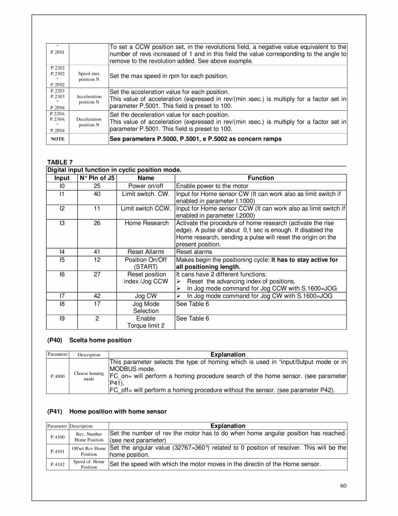
60
“
P.2F01 To set a CCW position set, in the revolutions field, a negative value equivalent to the number of revs increased of 1 and in this field the value corresponding to the angle to remove to the revolution added. See above example.
P.2202
P.2302
“ P.2F02
Speed max
position N Set the max speed in rpm for each position.
P.2203
P.2303 “
P.2F04
Acceleration position N
Set the acceleration value for each position. This value of acceleration (expressed in rev/(min xsec.) is multiply for a factor set in parameter P.5001. This field is preset to 100.
P.2204; P.2304;
“
P.2F04
Deceleration
position N
Set the deceleration value for each position. This value of acceleration (expressed in rev/(min xsec.) is multiply for a factor set in parameter P.5001. This field is preset to 100.
NOTE See parameters P.5000, P.5001, e P.5002 as concern ramps
TABLE 7 Digital input function in cyclic position mode.
Input N° Pin of J5 Name Function
I0 25 Power on/off Enable power to the motor
I1 40 Limit switch. CW. Input for Home sensor CW (It can work also as limit switch if enabled in parameter I.1000)
I2 11 Limit switch CCW. Input for Home sensor CCW (It can work also as limit switch if enabled in parameter I.2000)
I3 26 Home Research Activate the procedure of home research (activate the rise edge). A pulse of about 0,1 sec is enough. If disabled the Home research, sending a pulse will reset the origin on the present position.
I4 41 Reset Allarmi Reset alarms
I5 12 Position On/Off (START)
Makes begin the positioning cycle: It has to stay active for all positioning length.
I6 27 Reset position index /Jog CCW
It cans have 2 different functions: Reset the advancing index of positions. In Jog mode command for Jog CCW with S.1600=JOG
I7 42 Jog CW In Jog mode command for Jog CW with S.1600=JOG
I8 17 Jog Mode Selection
See Table 6
I9 2 Enable Torque limit 2
See Table 6
(P40) Scelta home position Parameter Description Explanation
P.4000 Choese homing
mode
This parameter selects the type of homing which is used in “input/0utput mode or in MODBUS mode. FC_on= will perform a homing procedure search of the home sensor. (see parameter P41). FC_off= will perform a homing procedure without the sensor. (see parameter P42).
(P41) Home position with home sensor Parameter Description Explanation
P.4100 Rev. Number
Home Position
Set the number of rev the motor has to do when home angular position has reached. (see next parameter)
P.4101 Offset Rev Home
Position
Set the angular value (32767=360°) related to 0 position of resolver. This will be the home position.
P.4102 Speed of Home
Position Set the speed with which the motor moves in the directin of the Home sensor.
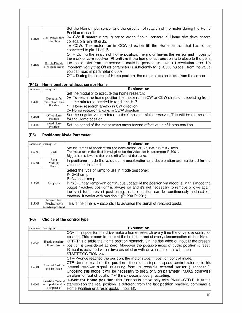
61
P.4103 Limit switch Stop /
Direction
Set the Home input sensor and the direction of rotation of the motor during the Home Position research. 0= CW: il motore ruota in senso orario fino al sensore di Home che deve essere collegato al pin 40 di J5. 1= CCW: The motor run in CCW direction till the Home sensor that has to be connected to pin 11 of J5
P.4104 Enable/Disable
zero mark search
On = During the search of Home position, the motor leaves the sensor and moves to the mark of zero resolver. Attention: if the home offset position is to close to the point the motor exits from the sensor, it could be possible to have a 1 revolution error. It’s important verify that Offset parameter is sufficiently far ( >3000 pulses ) from the value you can read in parameter d.0007 Off = During the search of Home position, the motor stops once exit from the sensor
(P42) Home position without sensor Home Parameter Description Explanation
P.4200
Direction for
research of Home
Position
Set the modality to execute the home research: 0= To reach the home position the motor run in CW or CCW direction depending from the min route needed to reach the H.P. 1= Home research always in CW direction 2= Home research always in CCW direction
P.4201 Offset Home
Position
Set the angular value related to the 0 position of the resolver. This will be the position for the Home position.
P.4202 Speed Home
Position Set the speed of the motor when move toward offset value of Home position
(P5) Positioner Mode Parameter Parameter Description Explanation
P.5000 Jerk
Set the ramps of acceleration and deceleration for S curve in r/(min x sec²) . The value set in this field is multiplied for the value set in parameter P.5001. Bigger is this lower is the round off effect of the curve.
P.5001 Ramp
Multiply
Factor
In positioner mode the value set in acceleration and deceleration are multiplied for the value set in this field
P.5002 Ramp type
Select the type of ramp to use in mode positioner: P-rS=S ramp P-rN=linear ramp P-rnC=Linear ramp with continuous update of the position via modbus. In this mode the output “reached position” is always on and it’s not necessary to remove or give again the start for a restart positioning, as the position can be continuously updated via modbus. It works with position 1 (P1200-P1201)
P.5003
Advance time
Reached quota
(reached position) This is the time [s = seconds ] to advance the signal of reached quota.
(P6) Choice of the control type Parameter Description Explanation
P.6000 Enable the alarm
of Home Position
ON=In this position the drive make a home research every time the drive lose control of position. This happen for sure at the first start and at every disconnection of the drive. OFF=This disable the Home position research. On the rise edge of input I3 the present position is considered as Zero. Moreover the possible index of cyclic position is reset. I3 input is activated when drive disabled or with drive enabled but with input START/POSITION low.
P.6001 Reached Position
control mode
CTR-P=once reached the position, the motor stops in position control mode. CTR-U=once reached the position , the motor stops in speed control refering to his internal resolver signal, releasing from its possible external sensor ( encoder ). Choosing this mode it will be necessary to set 2 or 3 on parameter P.6002 otherwise an alarm of “out of position” F19 may occur at every restarting.
P.6002
Function Mode of
start position after
a stop out of
position
0=Wait for Home position: this function is active only with P6001=CTR-P. If at the star/position the real position is different from the last position reached, command a Home Position or a reset quota. (input I3).
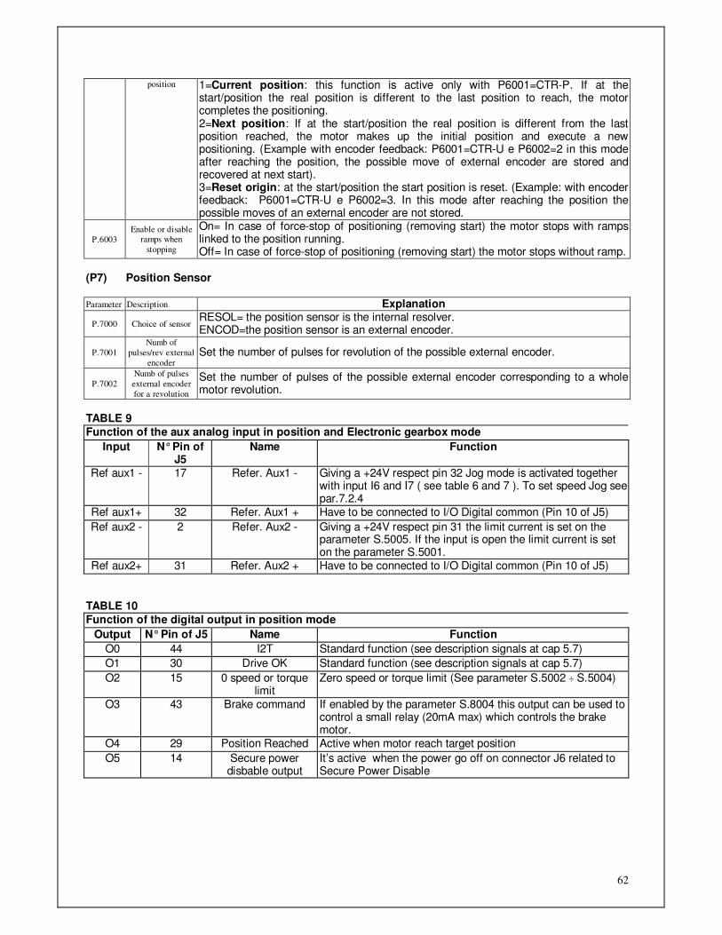
62
position 1=Current position: this function is active only with P6001=CTR-P. If at the start/position the real position is different to the last position to reach, the motor completes the positioning. 2=Next position: If at the start/position the real position is different from the last position reached, the motor makes up the initial position and execute a new positioning. (Example with encoder feedback: P6001=CTR-U e P6002=2 in this mode after reaching the position, the possible move of external encoder are stored and recovered at next start). 3=Reset origin: at the start/position the start position is reset. (Example: with encoder feedback: P6001=CTR-U e P6002=3. In this mode after reaching the position the possible moves of an external encoder are not stored.
P.6003
Enable or disable ramps when
stopping
On= In case of force-stop of positioning (removing start) the motor stops with ramps linked to the position running. Off= In case of force-stop of positioning (removing start) the motor stops without ramp.
(P7) Position Sensor Parameter Description Explanation
P.7000 Choice of sensor RESOL= the position sensor is the internal resolver. ENCOD=the position sensor is an external encoder.
P.7001
Numb of
pulses/rev external
encoder Set the number of pulses for revolution of the possible external encoder.
P.7002
Numb of pulses
external encoder
for a revolution
Set the number of pulses of the possible external encoder corresponding to a whole motor revolution.
TABLE 9 Function of the aux analog input in position and Electronic gearbox mode
Input N° Pin of J5
Name Function
Ref aux1 - 17 Refer. Aux1 - Giving a +24V respect pin 32 Jog mode is activated together with input I6 and I7 ( see table 6 and 7 ). To set speed Jog see par.7.2.4
Ref aux1+ 32 Refer. Aux1 + Have to be connected to I/O Digital common (Pin 10 of J5)
Ref aux2 - 2 Refer. Aux2 - Giving a +24V respect pin 31 the limit current is set on the parameter S.5005. If the input is open the limit current is set on the parameter S.5001.
Ref aux2+ 31 Refer. Aux2 + Have to be connected to I/O Digital common (Pin 10 of J5)
TABLE 10 Function of the digital output in position mode
Output N° Pin of J5 Name Function
O0 44 I2T Standard function (see description signals at cap 5.7)
O1 30 Drive OK Standard function (see description signals at cap 5.7)
O2 15 0 speed or torque limit
Zero speed or torque limit (See parameter S.5002 ÷ S.5004)
O3 43 Brake command If enabled by the parameter S.8004 this output can be used to control a small relay (20mA max) which controls the brake motor.
O4 29 Position Reached Active when motor reach target position
O5 14 Secure power disbable output
It’s active when the power go off on connector J6 related to Secure Power Disable

63
7.2.6 Menu “A” Control type “ELECTRONIC GEARBOX”
Once execute this selection the drive can synchronize its axis (with variable gears) in speed and space with a master axis. The master axis drive will send his speed and position through a frequency (signal type line drive). The reference can be furnished by two channels of a real or simulated encoder or from a signal in frequency with a further direction logic signal (see Par. 5.5). There’s an input for a possible phasing shift between two axes. There are 4 internal gears programmable, selectable from the user through 2 digital inputs. Otherwise it’s possible to set the change of gear in electronic potentiometer mode. Jog mode is selectable (see Tab. 8)
Menu Description Menu Description Parameter Description Range of Values Type
A.0 RATIO CHOICE A.0000 Choice of type of ratio 1-Ext / 2-SEL S
A.1 EXT RATIO A.1000 Delta Ratio. For time unit 0,001 – 1,000 S
ELEC. POTENTIOM A.1001 Time unit for Delta ratio 0,01 – 10,00 sec S
A.2 INTERNAL A.2000 Ratio 0 -8,000 ÷ 8,000 W
RATIOS A.2001 Ratio 1 -8,000 ÷ 8,000 W
A Electronic SELECTABLE A.2002 Ratio 2 -8,000 ÷ 8,000 W
Gearbox A.2003 Ratio 3 -8,000 ÷ 8,000 W
A.3 MASTER AXIS A.3000 Pulse per revolution 200 – 16384 S
PARAMETER A.3001 Mode frequency 1=Encoder; 2=f/Direction
3= pulse CW CCW
S
A.3002 Choice input I2: Limit switch CCW
or Shift phasing -
Fcccu / SFAS- S
A.3003 Threshold Target position pulse 1 ÷ 65535 W
A.4 AXIS A.4000 Shift phasing speed 0 – 200% S
SHIFT PHASING A.4001 Shift phasing ramp 1 – 10000 rp/min x sec S
PARAMETER A.4002 Shift phasing max time duration 0,01 – 10,00sec S
(A0) Choice the type of Ratio Parameter Description Explanation A.0000
Choice of ratio
This allows to select the type of ratio to use: 1-EST: set the ratio using digital input in motopotentiometer mode. See paragraph A1 2-SEL : set the ratio using digital input with the possibility to change the ratio among 4 ratios selectable. See A2 paragraph
(A1) Ratio setting through digital inputs in electronic potentiometer mode With this mode speed ratio can be changed through 2 digital inputs I6 e I7 (see table10). Ramp can be set through the 2 parameters A.1000 e A.1001. The ratio can be changed also with drive in Run. Parameter Description Explanation A.1000 Delta ratio for time
unit Set the value of the ratio variation for each time interval set in next parameter.
A.1001 Time unit for delta ratio
Set the rate of time to make the variation set in the previous parameter.
(A2) Setting of 4 ratios selectable through digital inputs Parameter Description Explanation A.2000 Ratio 0
A.2001 Ratio 1
A.2002 Ratio 2
A.2003 Ratio 3
Set the value of the ratio between master and slave axes that best suit your needs. Once set these values, the choice of the correct ratio to use can be done through the two digital inputs I6 and I7. Vedi Tabella 10
(A3) Master Axis parameter Parameter Description Explanation A.3000 Pulse per
revolution Set the number of pulses of master to complete a whole revolution of slave motor.
A.3001 Mode frequency This parameter allows to select the type of signals used for frequency reference 1 a-b = two signals shift-phased of 90° of a real or simulated encoder.
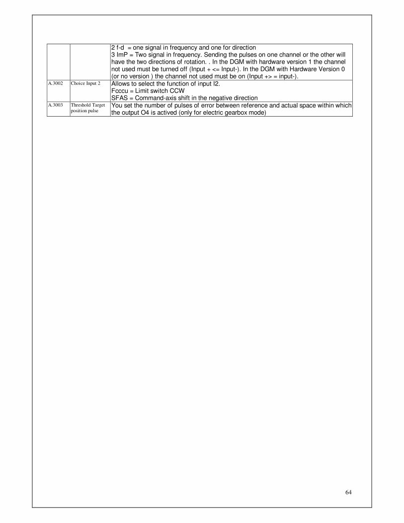
64
2 f-d = one signal in frequency and one for direction 3 ImP = Two signal in frequency. Sending the pulses on one channel or the other will have the two directions of rotation. . In the DGM with hardware version 1 the channel not used must be turned off (Input + <= Input-). In the DGM with Hardware Version 0 (or no version ) the channel not used must be on (Input +> = input-).
A.3002 Choice Input 2 Allows to select the function of input I2. Fcccu = Limit switch CCW SFAS = Command-axis shift in the negative direction
A.3003 Threshold Target
position pulse You set the number of pulses of error between reference and actual space within which the output O4 is actived (only for electric gearbox mode)

65
(A4) Shift phasing Axis Parameter Parameter Description Explanation A.4000 Shift phasing
speed Set a value in % of speed instantaneous ref. This value will be added to the main speed ref with the aim to obtain a shift phasing of slave shaft compared to the master shaft.
A.4001 Shift phasing ramp Sets an acceleration that will be add to the shift phasing speed. A.4002 Shift phasing max
time duration Set the max time duration to apply the shift phasing speed. If the shift phasing input will be fed for a higher time it will be deactivated. It will be necessary to remove and give again the command to execute a further correction.
TABLE 11
Digital inputs function in “Electronic gearbox” mode
Input N° Pin of J5 Name Function
I0 25 Power on/off Enable poser to the motor
I1 40 Limit switch. CW. Input of CW limit switch
I2 11 Limit switch CCW. Input of CCW limit switch
I3 26 Shift phasing Axis On the edge of this input it’s executed a shift phasing axis cycle depending on parameter set in “A.4”
I4 41 Reset Alarms Reset Alarms
I5 12 Start/Stop Enable speed ref. Furnishing this signal the motor follows the setting of speed reference with set ratios. Removing this signal the motor stops and an error is shown with message “Run” in menu “d.000”.
Code to select the ratios:
I6 I7 Ratio N.
I6 27 Increase ratio /choice int.ratio /Jog CCW
I7 42 Decrease ratio / choice internal ratio/ Jog CW
It cans have 3 different function: Mode “A.1” change the ratio
with ramp set by values in A.1000 e A.1001
In Mode “A.2” one of 4 internal ratios can be selected (See side table).
Jog mode (See set I8 input table 6) commands for Jog
with S.1600=JOG
0 1 0 1
0
0
1
1
0 1 2 3
I8 17 Jog Mode Selection
This activated the Jog mode. To use this pin as a digital input to 24V, connect pin 32 of J5 to GND of digital inputs (pin 10 of J5)
I9 2 Enable Torque limit 2
To use this pin as a digital input to 24V, connect pin 31 of J5 to GND of digital inputs (pin 10 of J5). With the input open the motor current limit is set by parameter S.5000. With the input at +24V the motor current is limited by the parameter S.5005 (torque limit 2)
Note: For use Input I8 and I9 see table 9
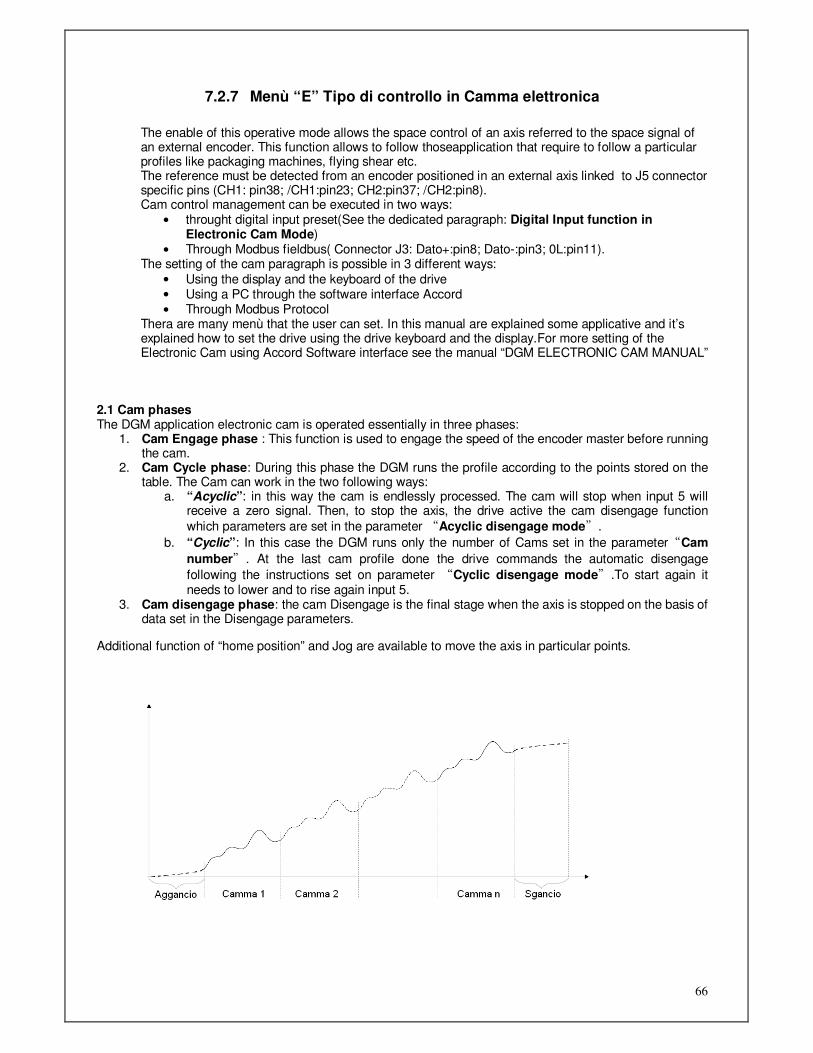
66
7.2.7 Menù “E” Tipo di controllo in Camma elettronica
The enable of this operative mode allows the space control of an axis referred to the space signal of an external encoder. This function allows to follow thoseapplication that require to follow a particular profiles like packaging machines, flying shear etc. The reference must be detected from an encoder positioned in an external axis linked to J5 connector specific pins (CH1: pin38; /CH1:pin23; CH2:pin37; /CH2:pin8). Cam control management can be executed in two ways:
• throught digital input preset(See the dedicated paragraph: Digital Input function in Electronic Cam Mode)
• Through Modbus fieldbus( Connector J3: Dato+:pin8; Dato-:pin3; 0L:pin11). The setting of the cam paragraph is possible in 3 different ways:
• Using the display and the keyboard of the drive • Using a PC through the software interface Accord
• Through Modbus Protocol Thera are many menù that the user can set. In this manual are explained some applicative and it’s explained how to set the drive using the drive keyboard and the display.For more setting of the Electronic Cam using Accord Software interface see the manual “DGM ELECTRONIC CAM MANUAL”
2.1 Cam phases The DGM application electronic cam is operated essentially in three phases:
1. Cam Engage phase : This function is used to engage the speed of the encoder master before running the cam.
2. Cam Cycle phase: During this phase the DGM runs the profile according to the points stored on the table. The Cam can work in the two following ways:
a. “Acyclic”: in this way the cam is endlessly processed. The cam will stop when input 5 will receive a zero signal. Then, to stop the axis, the drive active the cam disengage function
which parameters are set in the parameter “Acyclic disengage mode”.
b. “Cyclic”: In this case the DGM runs only the number of Cams set in the parameter“Cam
number”. At the last cam profile done the drive commands the automatic disengage
following the instructions set on parameter “Cyclic disengage mode”.To start again it needs to lower and to rise again input 5.
3. Cam disengage phase: the cam Disengage is the final stage when the axis is stopped on the basis of data set in the Disengage parameters.
Additional function of “home position” and Jog are available to move the axis in particular points.

67
Si elencano nella tabella sottostante i contenuti del menù “E”.
Menù Descrizione Menù Descrizione Menù Descrizione Parametro Descrizione Range valori Tipo
E.1 CAM E.1001 Table points number 16 - 256 S
TABLE E.1002 Table Index 0 - 255 S
E.1003 Cam table data 0 - 99999 S
E OPERATIVE E.2 CAM E.2001 Cam mode 1-ACl, 2-CLC S
MODE SETTING E.2002 Number cams 1 - 60000 S
ELECTRONIC E.2003 Encoder Numerator -32768 - +32767 W
CAM E.2004 Encoder Denominator 1 - 65535 W
E.2005 Frequency Mode 1-A b / 2-Fr9 S
E.2006/7 Master module 0 – 1048575 S
E.2008/9 Slave module 0 – 4194303 S
E.200A/B Synchronism phase 0 - 4194303 W
E.200C Enable Sync On/Off S
E.200D Input type sync 0:Enable 0V ; 24:Enable 24V S
E.200E Enable correction slave
module On/Off
E.3 ENGAGE E.3001 Engage mode 1-Imm, 2-FAS, 3-rmP S
CAM E.3002/3 Start engage 0 - 4194303 S
E.3004/5 Start ramp 0 - 4194303 S
(LOCK CAM) E.3006/7 Master engage space 1000 - 4194303 S
E.3008/9 Slave engage space 1000 - 4194303 S
E.4 DISENGAGE E.41 CYCLIC E.4101 Engage Type 1-ImS, 2-1mP, 3-FCS, 4-FCP S
CAM E.4102 Deceleration 1 – 60000 (rpm) W
E.4103 Type of position 0=Absolute, 1=Relative S
UNLOCK CAM E.4104 Revolutions -32768 - +32767 W
E.4105 Offset 0 - 32767 W
E.4106 Speed 1 - 9999 W
E.4107 Accel./Decel. 1 - 60000 W
E.42 ACYCLIC E.4201 Engage Type 1-ImS, 2-1mP S
E.4202 Deceleration 1 – 60000 (rpm) W
E.4203 Type of position 0=Assoluta, 1=Relativa S
E.4204 Revolutions -32768 - +32767 W
E.4205 Offset 0 - 32767 W
E.4206 Speed 1 - 9999 W
E.4207 Accel./Decel. 1 - 60000 W
E.5 HOME E.5001 Type of Origin search 0 - 35 W
POSITION E.5002 Revolutions -32768 - +32767 W
E.5003 Offset 0 - 32767 W
E.5004 Searching speed 1 - 9999 W
E.5005 Output speed 1 - 9999 W
E.5006 Accel./Decel. 1 - 60000 W
E.6 CAM JOG E.6001 Speed of Jog 0 - 9999 W
E.6002 Accel./Decel. 1 - 60000 W
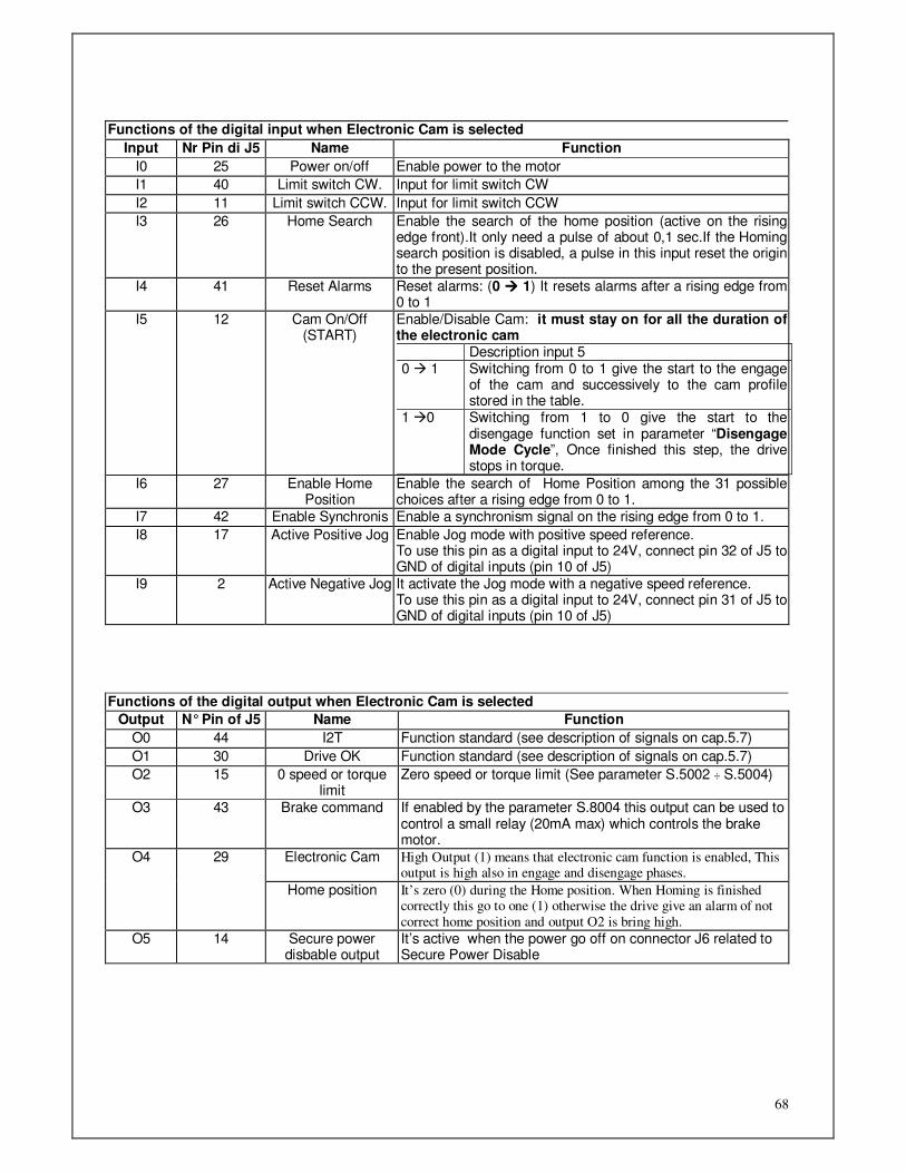
68
Functions of the digital input when Electronic Cam is selected
Input Nr Pin di J5 Name Function
I0 25 Power on/off Enable power to the motor
I1 40 Limit switch CW. Input for limit switch CW
I2 11 Limit switch CCW. Input for limit switch CCW
I3 26 Home Search Enable the search of the home position (active on the rising edge front).It only need a pulse of about 0,1 sec.If the Homing search position is disabled, a pulse in this input reset the origin to the present position.
I4 41 Reset Alarms Reset alarms: (0 1) It resets alarms after a rising edge from 0 to 1
I5 12 Cam On/Off (START)
Enable/Disable Cam: it must stay on for all the duration of the electronic cam Description input 5 0 1 Switching from 0 to 1 give the start to the engage
of the cam and successively to the cam profile stored in the table.
1 0 Switching from 1 to 0 give the start to the disengage function set in parameter “Disengage Mode Cycle”, Once finished this step, the drive stops in torque.
I6 27 Enable Home Position
Enable the search of Home Position among the 31 possible choices after a rising edge from 0 to 1.
I7 42 Enable Synchronis Enable a synchronism signal on the rising edge from 0 to 1.
I8 17 Active Positive Jog Enable Jog mode with positive speed reference. To use this pin as a digital input to 24V, connect pin 32 of J5 to GND of digital inputs (pin 10 of J5)
I9 2 Active Negative Jog It activate the Jog mode with a negative speed reference. To use this pin as a digital input to 24V, connect pin 31 of J5 to GND of digital inputs (pin 10 of J5)
Functions of the digital output when Electronic Cam is selected
Output N° Pin of J5 Name Function
O0 44 I2T Function standard (see description of signals on cap.5.7)
O1 30 Drive OK Function standard (see description of signals on cap.5.7)
O2 15 0 speed or torque limit
Zero speed or torque limit (See parameter S.5002 ÷ S.5004)
O3 43 Brake command If enabled by the parameter S.8004 this output can be used to control a small relay (20mA max) which controls the brake motor.
Electronic Cam High Output (1) means that electronic cam function is enabled, This output is high also in engage and disengage phases.
O4 29
Home position It’s zero (0) during the Home position. When Homing is finished correctly this go to one (1) otherwise the drive give an alarm of not
correct home position and output O2 is bring high.
O5 14 Secure power disbable output
It’s active when the power go off on connector J6 related to Secure Power Disable

69
Uscita O5
Ingresso I5
Translation from Italian to English of the graphic: Aggancio = Engage ; Camma= Cam; Sgangio = Disengage ; Ingresso= Input ; Uscita = Output
(E1) Table cam Setting Example: if you select a 16 points cam I must set E.1001=16.
Then you must set parameter E.1002=0 and push enter. Now you can set the correspondent value of f(x) in E.1003=0, and push enter to save. To set the next value of table set E.1002=1, then enter, then open menu E.1003 and set the wished value (E.1003=10), push enter to save. These sequece must be repeated for 16 times untill all cam points will be set. Note: this procedure is semplyfied usign the software ACCORD that is a PC software tool ( for Windows OS ) to interface with DGM drives.This software also give the possibility to have a linear or cubic polynomial interpolation of the curve.
Parameter Description Explanation E.1001 Cam Points Max number of points
E.1002 Table Index Set the value for the function which y=f(x) must be set on E.1003.
E.1003 Cam data Tabel cam data corresponding to the selected index on parameter E1002.
E.1002: x 0 1 2 3 4 ... 13 14 15
E.1003: f(x) 0 10 100 300 500 ... 10 5 0
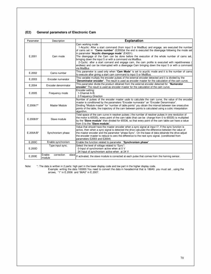
70
(E2) General parameters of Electronic Cam
Note: *: The data is written in 2 parts: high part in the lower display code and low part in the higher display code.
Example: writing the data 100000.You need to convert the data in hexadecimal that is 186A0. you must set , using the arrows, “1” in E.2006 and “86A0” in E.2007.
Parameter Description Explanation
E.2001 Cam mode
Cam working mode : 1-Acyclic: After a start command (from input 5 or ModBus) and engage, are executed the number of cams set in “Cams number” (E2002at the end is executed the disengage following the mode set in parameter “Acyclic disengage mode” (E4201). The disengage of the Cam can be done before the execution of the whole number of cams set, bringing down the input 5 or with a command via ModBus. 2-Cyclic: after a start comand and engage cam, the cam profile is executed with repetitiveness ( endless) and can be interrupted with a disengage Cam bringing down the input 5 or with a command via ModBus
E.2002 Cams number This parameter is used only when “Cam Mode” is set to acyclic mode and it is the number of cams to execute after giving a start cam command to input 5 or ModBus.
E.2003 Encoder numerator This variable multiply the encoder pulses of the external encoder detected and it is divided by the “Denominator encoder”. The result is used as encoder master for the calculation of the cam curve.
E.2004 Encoder denominator This parameter divide the product obtained from the external encoder detected for “Numerator encoder” The result is used as encoder master for the calculation of the cam curve.
E.2005 Frequency mode Encoder setting: 1-Channel A-B; 2-Frequency-Direction
E.2006/7* Master Module
Number of pulses of the encoder master usde to calculate the cam curve, the value of the encoder master is conditioned by the parameters “Encoder numerator” an “Encoder Denominator”. Dividing “Module master” for “number of table points” you obtain the interval between tow onsecutive points of the table, the trajectory of the cam between points is calculated using a cubic interpolation algorithm.
E.2008/9* Slave module
Total space of the cam curve in resolver pulses ( the number of resolver pulses in one revolution of the motor is 65535), every point of the cam table (that can be change from 0 to 65535) is multiplied by the “Slave module” then divided for 65536, so that every point of the cam table can have a value from 0 to the “Slave module”.
E.200A/B* Synchronism phase
Value that should have the master encoder when a sync signal at input I7; If the sync function is active, then when a sync signal is detected the drive calculate the difference between the value of the master encoder and the parameter “phase Sync”. On the base of data obtainde the drive adjust the encoder master to reduce to zero the difference to the next sync signal. (conditioned from parameters E2003 and E2004)
E.200C Enable synchronism Enable the function related to parameter “Synchronism phase”
E.200D Type input sync. Select the level of voltage related to “Sync”:
0-Input of synchronism active when at 0 V 24 Input of synchronism active when at 24 V
E.200E Enable correction slave module
If activated, the slave module is corrected at each pulse that comes from the homing sensor.

71
(E3) Engage Cam Parameters
Note: *: The data is written in 2 parts: high part in the lower display code and low part in the higher display code.
Example: writing the data 100000.You need to convert the data in hexadecimal that is 186A0. you must set , using the arrows, “1” in E.2006 and “86A0” in E.2007.
(E41) Parametri sgancio camma ciclico
Parameter Description Explanation
E.3001 Type of Engage
Select the engage mode: 1-Immediate engage: after start cam (from input 5 or ModBus)the drive starts immediatly to execute the cam profile. 2-Engage to a value of the master phase: After the start, the cam is executed when the master encoder has same value of parameter“Engage start phase” (E3002(H),E3003(L)) 3-Engage in ramp: with this option the drive made a trajectory in speed ramp to lock ( engage) to the speed of encoder master, the parameter “Engage space master” shows the space that the encoder master made in this phase, while the “Engage space slave” is the space covered by the slave (in resolver units) in the engage phase.The parameter “Start ramp phase” set the phase of the encoder master point to start the function of engage in ramp.
E.3002/3* Start engage phase
Space measured in encoder pulses (conditioned by parameter E2003 and E2004) that indicates the numerical value to arrange the start of the cam,, (Type of Engage[2]). This parameter is valid when “Engage mode” is set on monde “Engage to a value of master phase”,in this case the cam start when th encoder master is equal to the value set in this parameter.
E.3004/5* Start ramp phase
Space measured in encoder (conditioned by parameter E2003 and E2004) that indicates the phase master to start the engage of the cam in (Type of Engage [3]). The parameter “Start ramp phase” is valid when “Engage mode” is set to mode”Ramp engage”, in this case the engage in ramp speed start when the encoder master is equal to the value set in this parameter.
E.3006/7* Space Master
Space measured in encoder (conditioned by parameter E2003 and E2004) covered by the master during the phase of engage of the cam in ramp (Type of Engage [3]). This parameter is active only when “Engage mode is set to mode”Ramp engage”, and is the space measured in pulse covered by the encoder master during the engage phase.
E.3008/9* Space Slave
Space measured in resolver pulses by the motor axis, during the phase of engage in ramp of the cam (Type of Engage [3 This parameter is active only when “Engage mode is set to mode”Ramp engage”, and is the space measured in resolver pulses of the motor axis during the phase of engage in ramp ( the numeber of resolver pulses in 1 revolution is equal at 65535).
Parameter Description Explanation
E.4101 Type of disengage
Setting cyclic cam,this parameter selects the mode of disengage of the cam when input 5 is lowered: 1-Disengage at the end of the cam in speed ramp: When the cam profile is finished the drive start an arrest in speed ramp with deceleration set in parameter E4102 “Deceleration”. 2-Disengage at the end of cam in position: When the cam profile is finished the drive start an arrest at a defined position given by parameters E4104 “Disengage revolutions” and E4105 “Disengage Offset”. 3-Immediate disengage in speed ramp:When switching to zero the input 5, the cam is interrupted and it is commanded an immediate arrest in speed ramp following parameter E4102 “Deceleration”. 4-Immediate disengage in position: the switch from 1 to 0 of input 5 give immediate interruption to the cam and the execution of a positioning following the parameters E4104 “Disengage revolutions” and E4105 “Disengage Offset”.
E.4102 Deceleration This parameter set the deceleration for the arrest in ramp when “Cyclic disengage mode” is set to “Disengage at the end of cam in speed ramp” [1] or “Immediate disengage in speed ramp” [3].
E.4103 Type of quota
(position)
Type of quota, relative or absolute (“Cyclic disengage mode” (E4101) set to [2] or [4]) 0- Absolute 1- Relative
E.4104 Disengage revolutions Number of motor revolutions covered by the drive, during the disengage phase (“Cyclic disengage mode” (E4101) and set to [2] or [4]).
E.4105 Quota-Offset Disengage Offset on one motor revolution of the space covered by the during the disengage phase (“Cyclic disengage mode” (E4101) and set to [2] or [4]).
E.4106 Speed Speed of the disengage position (“Cyclic disengage mode” (E4101) and set to [2] or [4]).
E.4107 Accel./Decel. Value of acceleration and deceleration of the disengage position (“Cyclic disengage mode” (E4101) and set to [2] or [4]).

72
(E42) Parametri sgancio camma Aciclico
(E5) Parameters Home Position
Selection of the type of home position search method (E.5001)
Parameter Description Explanation
E.4201 Type of disengage
With Acyclic mode this parameter selects the cam disengage mode at the end of the number of cams set in parameter “Cams number” (E2002): 1-Disengage at the end of cam in speed ramp: when the number of cam set in parameter “Cams number” are completely finishe, the drive command a stop in speed ramp with deceleration set in parameter E4202 “Deceleration”. 2-Disengage at the end of cam with positioning: Once completely executed the number of cams set on parameter “Cams number” the drive command a positioning following the parameters E4204 “Disengage revolutions“ and E4205 “Offset sgancio”.
E.4202 Deceleration Deceleration speed when “Acyclic disengage mode” (E4201) is set at [1]
E.4203 Type of quota
(position)
Type of quota relative or absolute (“Acyclic disengage mode” (E4201) is set to [2]) 0- Assoluta
1- Relativa
E.4204 Disengage revolutions Number of motor revolution made by the drive during the disengage phase (“Acyclic disengage mode” (E4201) set at [2]).
E.4205 Quota-Offset Disengage Offset (“Acyclic disengage mode” (E4201) set at [2])
E.4206 Speed Speed of disengage quota (“Acyclic disengage mode” (E4201) set at [2])
E.4207 Accel./Decel. Value of acceleration and deceleration of the disengage quota (“Acyclic disengage mode” (E4201) set at [2]).
Parameter Description Explanation E.5001 Origin search type It select the type of home position (see below table)
E.5002 Revolutions It set the number of revolution to cover at the end of home position process.
E.5003 Offset Offset inside a single turn of the motor to cover at the end of the home position process.
E.5004 Search speed Speed to search the limit switch or the home
E.5005 Output speed Output speed from the limit switch sensor or home.
E.5006 Accel./Decel. Value of acceleration and deceleration
Type of Home Position E.5001
Method with zero mark
Method without
zero mark
Type of sensor used
0 0 No homing selected
1 17 Sensor CCW
2 18 Sensor CW
3 19 Home sensor ( on rising edge)
4 20 Home sensor ( on rising edge)
5 21 Home sensor ( on rising edge)
6 22 Home sensor ( on rising edge)
7 23 Home sensor ( on the level ) positive speed search
8 24 Home sensor ( on the level ) positive speed search
9 25 Home sensor ( on the level ) positive speed search
10 26 Home sensor ( on the level ) positive speed search
11 27 Home sensor ( on the level ) positive speed search
12 28 Home sensor ( on the level ) positive speed search
13 29 Home sensor ( on the level ) positive speed search
14 30 Home sensor ( on the level ) positive speed search
15 31 Reserved
16 32 Reserved
33 Without sensor (on the zero mark) negative speed search
34 Without sensor (on the zero mark) positive speed search
35 Home positionon present value

73
Method 0 - No homing operation required At start the value of measured position is reset and set as zero point of the drive. Method 1 - Homing on the negative limit switch and index pulse The drive start with home position process moving in negative direction towards the limit switch sensor CCW. Once touched the sensor, it turns back to leave the sensor with a slow speed and moves in opposite direction towards the zero mark of resolver. The point reached become the new zero for the drive.
Method 1 – Homing search CCW and zero mark resolver ( impulso di zero = zero mark; Fine corsa CCW = Limit switch
CCW) Method 2 - Homing on the positive limit switch and index pulse The drive start the home position process moving in positive direction towards the limit switch CW. Once touched the sensor, it turns back to leave the limit switch at slow speed and moves, always in the same opposite direction, towards the zero mark of the resolver. The point reached become the new zero of the drive.
Method 2 - Homing search CW and zero mark resolver ( impulso di zero = zero mark; Fine corsa CW = Limit switch CW) Method 3 - Homing on the positive home switch and index pulse The state of the home sensor give indication about the direction to move for the search the sensor. If the input of home is low level the motor will rotate in CW, when is detected a switch signal on the home sensor the motor is stopped and succesively positioned on the zero mark of the resolver moving CCW . If the home input is high level the motor will rotate in CCW, when is detected a switch signal on the home sensor the motor is stopped and succesively positioned on the zero mark of the resolver moving CW.
Illustrazione 17: Method 3 – Origin search on the Home sensor ( impulso di zero = zero Mark ) Method 4 - Homing on the positive home switch and index pulse The state of the home sensor give indication about the direction to move for the search the sensor. If the input of home is high level the motor will rotate in CCW, when is detected a switch signal on the home sensor the motor is stopped and succesively positioned on the zero mark of the resolver moving CW .

74
If the home input is low level the motor will rotate in CW, when is detected a switch signal on the home sensor the motor is stopped and succesively positioned on the zero mark of the resolver moving CW.
Method 4 - Origin search on the Home sensor ( impulso di zero = zero Mark )
Method 5 - Homing on the negative home switch and index pulse The state of the home sensor give indication about the direction to move for the search the sensor. If the input of home is low level the motor will rotate in CCW, when is detected a switch signal on the home sensor the motor is stopped and succesively positioned on the zero mark of the resolver moving CW . If the home input is high level the motor will rotate in CW, when is detected a switch signal on the home sensor the motor is stopped and succesively positioned on the zero mark of the resolver moving CW.
Method 5 - Origin search on the Home sensor ( impulso di zero = zero Mark )
Metodo 6 - Homing on the negative home switch and index pulse The state of the home sensor give indication about the direction to move for the search the sensor. If the input of home is high level the motor will rotate in CW, when is detected a switch signal on the home sensor the motor is stopped and succesively positioned on the zero mark of the resolver moving CCW . If the home input is low level the motor will rotate in CCW, when is detected a switch signal on the home sensor the motor is stopped and succesively positioned on the zero mark of the resolver moving CCW.
Method 6 - Origin search on the Home sensor ( impulso di zero = zero Mark )

DGM MANUALE D’USO ED INSTALLAZIONE REV N°6_03
75
Method 7 - Homing on the home switch and index pulse The search direction is made in CW, once detected the home sensor, the drive moves the motor at low speed, in CCW direction to leave the senosr , then it execute a positioning CCW on the zero resolver In case the CW limit switch is touched, the rotation is inverted to move the motor on the home sensor. Metodo 8 - Homing on the home switch and index pulse The search direction of home is made in CW direction , once detected the home senosor, the drive shift the motor at low speed in CCW direction to leave the sensor, then it moves in CW direction on the zero resolver mark.In case the CW limit switch is reached, the rotation is inverted to move the motor on the home sensor. Method 9 - Homing on the home switch and index pulse The search of the home sensor is made in CW direction, once detected the home sensor the drive shift the motor at low speed in CW direction to leave the sensor, then it moves in CCW direction on the zero resolver mark. In case the CW limit switch is reached, the rotation direction is inverted so to move the motor on the home sensor. Method 10 - Homing on the home switch and index pulse The search of the home sensor is made in CW direction, once detected the home sensor the drive shift the motor at low speed in CW direction to leave the sensor, then it moves in CW direction on the zero resolver mark. In case the CW limit switch is reached, the rotation direction is inverted so to move the motor on the home sensor.
Method 7,8,9,10 – Origin search on home sensor
Metodo 11 - Homing on the home switch and index pulse The search of the home sensor is made in CCW direction, once detected the home sensor the drive shift the motor at low speed in CW direction to leave the sensor, then it moves in CW direction on the zero resolver mark. In case the CCW limit switch is reached, the rotation direction is inverted so to move the motor on the home sensor. Metodo 12 - Homing on the home switch and index pulse The search of the home sensor is made in CCW direction, once detected the home sensor the drive shift the motor at low speed in CW direction to leave the sensor, then it moves in CCW direction on the zero resolver mark. In case the CCW limit switch is reached, the rotation direction is inverted so to move the motor on the home sensor. Metodo 13 - Homing on the home switch and index pulse The search of the home sensor is made in CCW direction, once detected the home sensor the drive shift the motor at low speed in CCW direction to leave the sensor, then it moves in CW direction on the zero resolver mark. In case the CCW limit switch is reached, the rotation direction is inverted so to move the motor on the home sensor. Metodo 14 - Homing on the home switch and index pulse The search of the home sensor is made in CCW direction, once detected the home sensor the drive shift the motor at low speed in CW direction to leave the sensor, then it moves in CCW direction on the zero resolver mark. In case the CCW limit switch is reached, the rotation direction is inverted so to move the motor on the home sensor.

76
Method 11,12, 13, 14 - Origin search on home sensor
Methods from 17 to 30 The method of origin from 17 to 30, correspond respectively to the method from 1 to 14 with the difference that in this case the zero mark search is not executed. For example the method 17 and 18 are executed as showned in the pictures below:
Method 17 – Origin search on CCW limit switch
Method 18 – origin search on CW limit switch
Metodo 33 – Index pulse homing (negative direction) Starting from the point where it is, the drive moves in negative direction on the zero mark of the resolver. Once reached this point, it becomes the zero of the drive. Metodo 34 - Homing on index pulse (positive direction) Starting from the point where it is, the drive moves in positive direction on the zero mark of the resolver. Once reached this point, it becomes the zero of the drive.
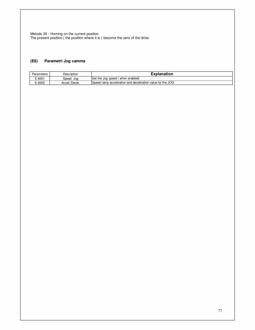
77
Metodo 35 - Homing on the current position The present position ( the position where it is ) become the zero of the drive.
(E6) Parametri Jog camma
Parameters Description Explanation E.6001 Speed Jog Set the Jog speed ( when enabled)
E.6002 Accel./Decel. Speed ramp acceleration and deceleration value for the JOG
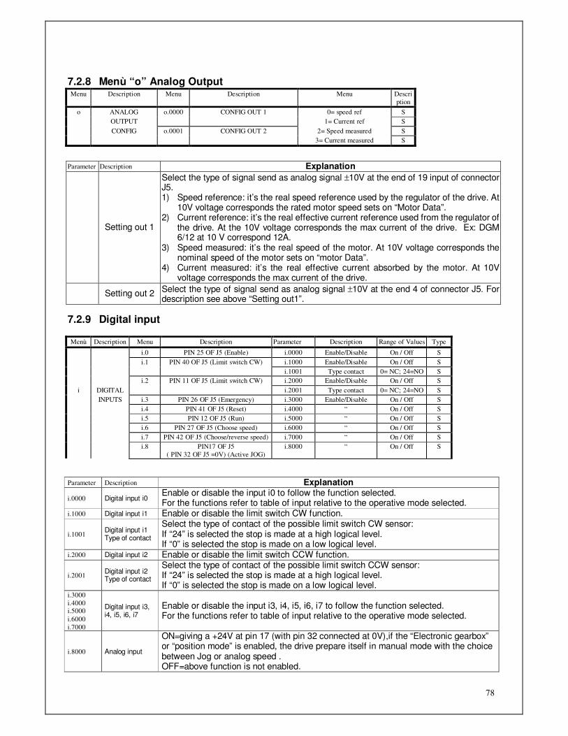
78
7.2.8 Menù “o” Analog Output Menu Description Menu Description Menu Descri
ption
o ANALOG o.0000 CONFIG OUT 1 0= speed ref S
OUTPUT 1= Current ref S
CONFIG o.0001 CONFIG OUT 2 2= Speed measured S
3= Current measured S
Parameter Description Explanation
Setting out 1
Select the type of signal send as analog signal ±10V at the end of 19 input of connector J5. 1) Speed reference: it’s the real speed reference used by the regulator of the drive. At
10V voltage corresponds the rated motor speed sets on “Motor Data”. 2) Current reference: it’s the real effective current reference used from the regulator of
the drive. At the 10V voltage corresponds the max current of the drive. Ex: DGM 6/12 at 10 V correspond 12A.
3) Speed measured: it’s the real speed of the motor. At 10V voltage corresponds the nominal speed of the motor sets on “motor Data”.
4) Current measured: it’s the real effective current absorbed by the motor. At 10V voltage corresponds the max current of the drive.
Setting out 2 Select the type of signal send as analog signal ±10V at the end 4 of connector J5. For
description see above “Setting out1”.
7.2.9 Digital input Menù Description Menu Description Parameter Description Range of Values Type
i.0 PIN 25 OF J5 (Enable) i.0000 Enable/Disable On / Off S
i.1 PIN 40 OF J5 (Limit switch CW) i.1000 Enable/Disable On / Off S
i.1001 Type contact 0= NC; 24=NO S
i.2 PIN 11 OF J5 (Limit switch CW) i.2000 Enable/Disable On / Off S
i DIGITAL i.2001 Type contact 0= NC; 24=NO S
INPUTS i.3 PIN 26 OF J5 (Emergency) i.3000 Enable/Disable On / Off S
i.4 PIN 41 OF J5 (Reset) i.4000 “ On / Off S
i.5 PIN 12 OF J5 (Run) i.5000 “ On / Off S
i.6 PIN 27 OF J5 (Choose speed) i.6000 “ On / Off S
i.7 PIN 42 OF J5 (Choose/reverse speed) i.7000 “ On / Off S
i.8 PIN17 OF J5
( PIN 32 OF J5 =0V) (Active JOG)
i.8000 “ On / Off S
Parameter Description Explanation
i.0000 Digital input i0 Enable or disable the input i0 to follow the function selected. For the functions refer to table of input relative to the operative mode selected.
i.1000 Digital input i1 Enable or disable the limit switch CW function.
i.1001 Digital input i1 Type of contact
Select the type of contact of the possible limit switch CW sensor: If “24” is selected the stop is made at a high logical level. If “0” is selected the stop is made on a low logical level.
i.2000 Digital input i2 Enable or disable the limit switch CCW function.
i.2001 Digital input i2 Type of contact
Select the type of contact of the possible limit switch CCW sensor: If “24” is selected the stop is made at a high logical level. If “0” is selected the stop is made on a low logical level.
i.3000
i.4000 i.5000
i.6000
i.7000
Digital input i3, i4, i5, i6, i7
Enable or disable the input i3, i4, i5, i6, i7 to follow the function selected. For the functions refer to table of input relative to the operative mode selected.
i.8000 Analog input
ON=giving a +24V at pin 17 (with pin 32 connected at 0V),if the “Electronic gearbox” or “position mode” is enabled, the drive prepare itself in manual mode with the choice between Jog or analog speed . OFF=above function is not enabled.
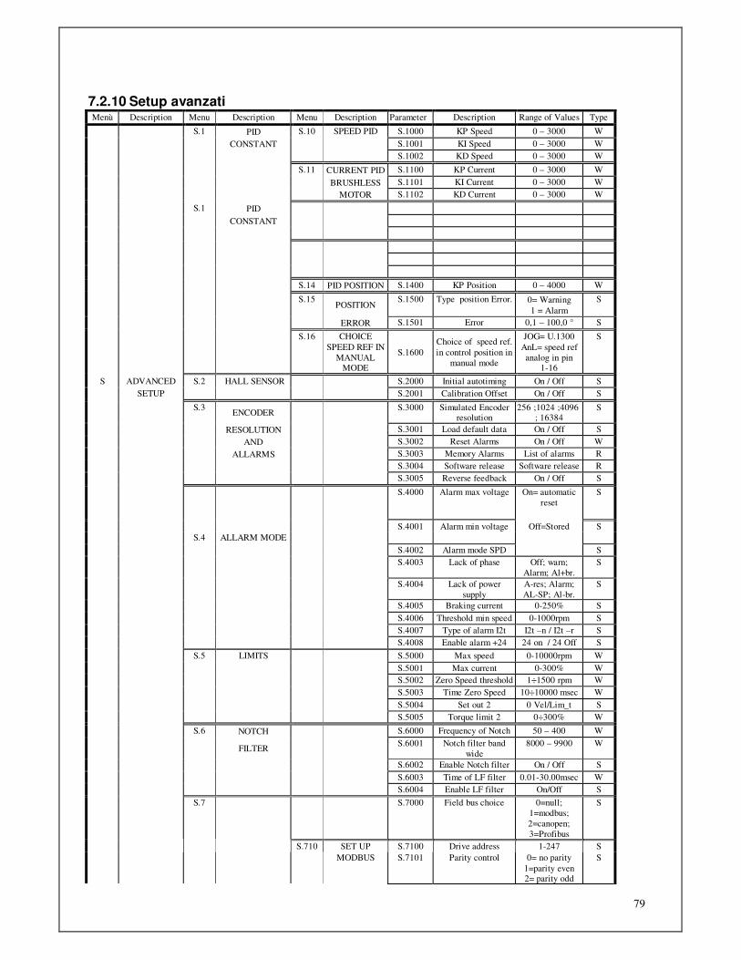
79
7.2.10 Setup avanzati Menù Description Menu Description Menu Description Parameter Description Range of Values Type
S.1 PID S.10 SPEED PID S.1000 KP Speed 0 – 3000 W
CONSTANT S.1001 KI Speed 0 – 3000 W
S.1002 KD Speed 0 – 3000 W
S.11 CURRENT PID S.1100 KP Current 0 – 3000 W
BRUSHLESS S.1101 KI Current 0 – 3000 W
MOTOR S.1102 KD Current 0 – 3000 W
S.1 PID
CONSTANT
S.14 PID POSITION S.1400 KP Position 0 – 4000 W
S.15 POSITION
S.1500 Type position Error. 0= Warning
1 = Alarm
S
ERROR S.1501 Error 0,1 – 100,0 ° S
S.16 CHOICE
SPEED REF IN
MANUAL MODE
S.1600
Choice of speed ref.
in control position in
manual mode
JOG= U.1300
AnL= speed ref
analog in pin 1-16
S
S ADVANCED S.2 HALL SENSOR S.2000 Initial autotiming On / Off S
SETUP S.2001 Calibration Offset On / Off S
S.3 ENCODER
S.3000 Simulated Encoder resolution
256 ;1024 ;4096 ; 16384
S
RESOLUTION S.3001 Load default data On / Off S
AND S.3002 Reset Alarms On / Off W
ALLARMS S.3003 Memory Alarms List of alarms R
S.3004 Software release Software release R
S.3005 Reverse feedback On / Off S
S.4000 Alarm max voltage On= automatic
reset
S
S.4001 Alarm min voltage Off=Stored S
S.4 ALLARM MODE
S.4002 Alarm mode SPD S
S.4003 Lack of phase Off; warn;
Alarm; Al+br.
S
S.4004 Lack of power
supply
A-res; Alarm;
AL-SP; Al-br.
S
S.4005 Braking current 0-250% S
S.4006 Threshold min speed 0-1000rpm S
S.4007 Type of alarm I2t I2t –n / I2t –r S
S.4008 Enable alarm +24 24 on / 24 Off S
S.5 LIMITS S.5000 Max speed 0-10000rpm W
S.5001 Max current 0-300% W
S.5002 Zero Speed threshold 1÷1500 rpm W
S.5003 Time Zero Speed 10÷10000 msec W
S.5004 Set out 2 0 Vel/Lim_t S
S.5005 Torque limit 2 0÷300% W
S.6 NOTCH S.6000 Frequency of Notch 50 – 400 W
FILTER
S.6001 Notch filter band
wide
8000 – 9900 W
S.6002 Enable Notch filter On / Off S
S.6003 Time of LF filter 0.01-30.00msec W
S.6004 Enable LF filter On/Off S
S.7 S.7000 Field bus choice 0=null;
1=modbus;
2=canopen;
3=Profibus
S
S.710 SET UP S.7100 Drive address 1-247 S
MODBUS S.7101 Parity control 0= no parity
1=parity even 2= parity odd
S
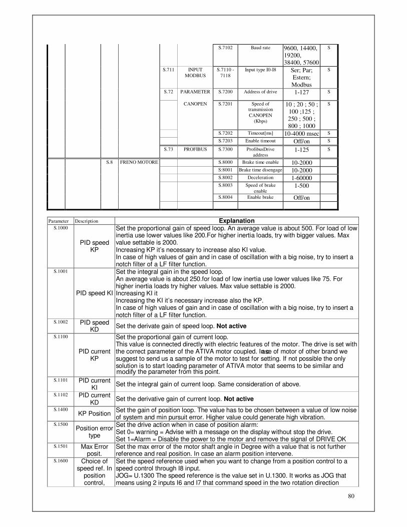
80
S.7102 Baud rate 9600, 14400,
19200,
38400, 57600
S
S.711 INPUT
MODBUS
S.7110 -
7118
Input type I0-I8 Ser; Par;
Estern;
Modbus
S
S.72 PARAMETER S.7200 Address of drive 1-127 S
CANOPEN S.7201 Speed of transmission
CANOPEN
(Kbps)
10 ; 20 ; 50 ;
100 ;125 ;
250 ; 500 ;
800 ; 1000
S
S.7202 Timeout[ms] 10-4000 msec S
S.7203 Enable timeout Off/on S
S.73 PROFIBUS S.7300 ProfibusDrive
address 1-125 S
S.8 FRENO MOTORE S.8000 Brake time enable 10-2000
S:8001 Brake time disengage 10-2000
S.8002 Deceleration 1-60000
S.8003 Speed of brake
enable 1-500
S.8004 Enable brake Off/on
Parameter Description Explanation S.1000
PID speed KP
Set the proportional gain of speed loop. An average value is about 500. For load of low inertia use lower values like 200.For higher inertia loads, try with bigger values. Max value settable is 2000. Increasing KP it’s necessary to increase also KI value. In case of high values of gain and in case of oscillation with a big noise, try to insert a notch filter of a LF filter function.
S.1001
PID speed KI
Set the integral gain in the speed loop. An average value is about 250.for load of low inertia use lower values like 75. For higher inertia loads try higher values. Max value settable is 2000. Increasing KI it Increasing the KI it’s necessary increase also the KP. In case of high values of gain and in case of oscillation with a big noise, try to insert a notch filter of a LF filter function.
S.1002 PID speed KD
Set the derivate gain of speed loop. Not active
S.1100
PID current KP
Set the proportional gain of current loop. This value is connected directly with electric features of the motor. The drive is set with the correct parameter of the ATIVA motor coupled. In case of motor of other brand we suggest to send us a sample of the motor to test for setting. If not possible the only solution is to start loading parameter of ATIVA motor that seems to be similar and
the parameter from this point.
S.1101 PID current KI
Set the integral gain of current loop. Same consideration of above.
S.1102 PID current KD
Set the derivative gain of current loop. Not active
S.1400 KP Position
Set the gain of position loop. The value has to be chosen between a value of low noise of system and min pursuit error. Higher value could generate high vibration.
S.1500 Position error
type
Set the drive action when in case of position alarm: Set 0= warning = Advise with a message on the display without stop the drive. Set 1=Alarm = Disable the power to the motor and remove the signal of DRIVE OK
S.1501 Max Error posit.
Set the max error of the motor shaft angle in Degree with a value that is not further reference and real position. In case an alarm position intervene.
S.1600 Choice of speed ref. In
position control,
Set the speed reference used when you want to change from a position control to a speed control through I8 input. JOG= U.1300 The speed reference is the value set in U.1300. It works as JOG that means using 2 inputs I6 and I7 that command speed in the two rotation direction
modify

81
manual mode AnL= ref.speed analog in pin 1-16.The drive change to speed ref set on the input of main speed (pin1-16)
S.2000 Sensor Hall
→ Autoset. Initial
Set ON at every start the drive execute an automatic verify and setting of the OFFSET on the current measured. In some application where the drive is disabled and current is not zero, this process can be avoid setting OFF. Standard setting is ON.
S.2001 Sensor Hall
→ Calibration Offset
With drive disabled it’s possible to do a process of calibration equal to the initial autotiming, setting On+ ENTER.
S.3000
Resolution Encoder
Simulated
Set the pulses at rev for the simulated encoder. The max value selectable depends from the speed motor data set on parameter m.1001. With motors up to 1000rpm it’s possible to select the value 16384. With motors from 1000 to 4500 rpm the max value settable is 4096. With motors exceeding the 4500rpm the max value settable is 1024.
S.3001 Load default
Set “On” + ENTER the default values of all parameter are loaded in Eeprom (except reserved area values)
S.3002
Reset Alarms Set On + ENTER all alarms are deleted Attention: if external command of start is present, it may occur that motor start again suddenly in case of reset.
S.3003 Alarm stored This parameter shows the last 16 alarms
S.3004 Software release
It shows the release of the software.
S.3005 Reverse feedback
By setting to "On" reverses the counting direction of the resolver. With ATIVA motors, with positive speed and positions the motor rotates counterclockwise.
S.4000 Max voltage
alarm
Set on “Off” the alarm of max voltage is stored and it needs a reset or a switching on to reset the alarm. Setting “On” the alarm has reset automatically as soon as the voltage goes down to the max value.
S.4001 Min voltage
alarm
Setting “Off” the alarm of min Voltage is stored and it needs a reset or a switching on to reset the alarm. Setting “On” the alarm has reset automatically as soon as the voltage goes up to the min.
S.4002 Alarm mode
SPD
By setting "Off" alarm circuit security SPD is stored and you need a reset or a power on to reset the alarm. If you set "On", the alarm will automatically reset as soon as the contacts of the safety circuit is closed again.
S.4003
No Phase
The drive immediately detects the lack of a phase in power supply line. This parameter allows to choose the behaviour to follow in case of an event of this type: Off= Lack phase control not enabled Warn= if happen the display shows message “F 06” Alarm=if happen the drive is disabled and the signal “drive Ok” removed, the motor stop for inertia and display shows “FA 06”message. Al+br= if happen the drive verify the speed of the motor and if it exceed the threshold set in S.4006, emergency stop process in current limit will be enabled (set in S. 4005) using the energy returned from load. So once speed motor is less than value set in S.4006 the drive disables and output OUT3 is brought down. On display “FA 06”message has shown.
S.4004
No Power supply
The drive immediately detects the absence of the power line , signaling with the message " FA05 ." This parameter selects the type of behavior to do in case of an event of this type : A- res = When it detects a power loss the drive is disabled , the motor stop for inertia and the alarm automatically resets when the power voltage returns. ALarm = When it detects a power loss the drive is disabled and the motor stop for inertia; the alarm is saved and when the power returns you need a reset command to reset the Drive AL- SP = When it detects a power loss, the drive check the speed of the motor, and if this is greater than the threshold set in S.4006 , enables a procedure for emergency stop ramp using the energy returned by the load. The slope of the ramp is set to the parameter U.4002 . When the motor speed is less than S.4006 the drive is disabled . The display shows the message "FA 05 ." ; the alarm is saved and when the power returns you need a reset command to reset the Drive. Al- br = When it detects a power loss the drive checks the speed of the motor and if this is greater than the threshold set in S.4006 enables a procedure for emergency stop
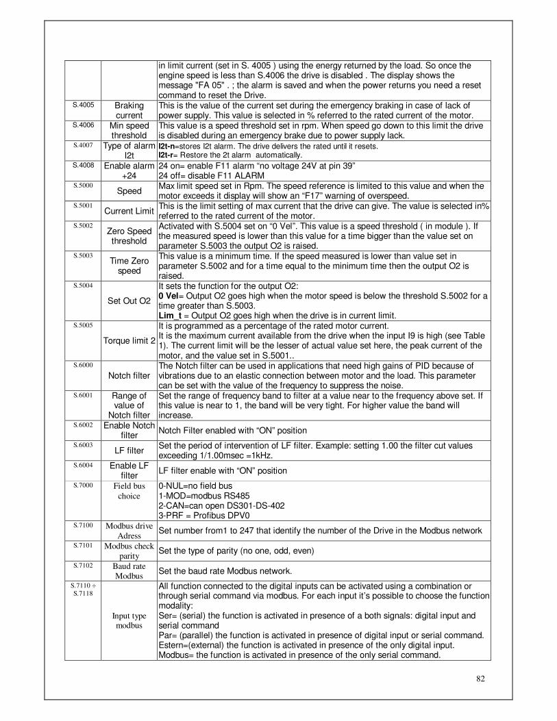
82
in limit current (set in S. 4005 ) using the energy returned by the load. So once the engine speed is less than S.4006 the drive is disabled . The display shows the message "FA 05" . ; the alarm is saved and when the power returns you need a reset command to reset the Drive.
S.4005 Braking current
This is the value of the current set during the emergency braking in case of lack of power supply. This value is selected in % referred to the rated current of the motor.
S.4006 Min speed threshold
This value is a speed threshold set in rpm. When speed go down to this limit the drive is disabled during an emergency brake due to power supply lack.
S.4007 Type of alarm I2t
I2t-n=stores I2t alarm. The drive delivers the rated until it resets. I2t-r= Restore the 2t alarm automatically.
S.4008 Enable alarm +24
24 on= enable F11 alarm “no voltage 24V at pin 39” 24 off= disable F11 ALARM
S.5000 Speed
Max limit speed set in Rpm. The speed reference is limited to this value and when the motor exceeds it display will show an “F17” warning of overspeed.
S.5001 Current Limit
This is the limit setting of max current that the drive can give. The value is selected in% referred to the rated current of the motor.
S.5002 Zero Speed threshold
Activated with S.5004 set on “0 Vel”. This value is a speed threshold ( in module ). If the measured speed is lower than this value for a time bigger than the value set on parameter S.5003 the output O2 is raised.
S.5003 Time Zero
speed
This value is a minimum time. If the speed measured is lower than value set in parameter S.5002 and for a time equal to the minimum time then the output O2 is raised.
S.5004
Set Out O2
It sets the function for the output O2: 0 Vel= Output O2 goes high when the motor speed is below the threshold S.5002 for a time greater than S.5003. Lim_t = Output O2 goes high when the drive is in current limit.
S.5005
Torque limit 2
It is programmed as a percentage of the rated motor current. It is the maximum current available from the drive when the input I9 is high (see Table 1). The current limit will be the lesser of actual value set here, the peak current of the motor, and the value set in S.5001..
S.6000
Notch filter The Notch filter can be used in applications that need high gains of PID because of vibrations due to an elastic connection between motor and the load. This parameter can be set with the value of the frequency to suppress the noise.
S.6001 Range of value of
Notch filter
Set the range of frequency band to filter at a value near to the frequency above set. If this value is near to 1, the band will be very tight. For higher value the band will increase.
S.6002 Enable Notch filter
Notch Filter enabled with “ON” position
S.6003 LF filter
Set the period of intervention of LF filter. Example: setting 1.00 the filter cut values exceeding 1/1.00msec =1kHz.
S.6004 Enable LF filter
LF filter enable with “ON” position
S.7000 Field bus
choice
0-NUL=no field bus 1-MOD=modbus RS485 2-CAN=can open DS301-DS-402 3-PRF = Profibus DPV0
S.7100 Modbus drive
Adress Set number from1 to 247 that identify the number of the Drive in the Modbus network
S.7101 Modbus check
parity Set the type of parity (no one, odd, even)
S.7102 Baud rate
Modbus Set the baud rate Modbus network.
S.7110 ÷
S.7118
Input type modbus
All function connected to the digital inputs can be activated using a combination or through serial command via modbus. For each input it’s possible to choose the function modality: Ser= (serial) the function is activated in presence of a both signals: digital input and serial command Par= (parallel) the function is activated in presence of digital input or serial command. Estern=(external) the function is activated in presence of the only digital input. Modbus= the function is activated in presence of the only serial command.

83
S.7200 Address drive
Canopen Set number from 1 to 127 that identify the number of drive in the Canbus net
S.7201 Baud rate
Canopen Set the baud rate of Canbus net
S.7202
Timeout
Timeout value. Maximum time of waiting before disconnecting the drive without receiving any signal from the fieldbus. In case of timeout the motor is stopped as configured in parameter Ox.6007. Furthermore there is a FA20 alarm shown on the display
S.7203 Enable timeout This enable or disable the timeout
S.7300 Profibus Drive
Address It’s possible to set from 1 to 125 drive in the same Profibus web
S.8000 Brake enabling
time
This is a time Setting from 10 ms to 2000ms that allows to stop the motor in torque to satisfy the electromechanic time of brake coupling. After this time the drive is disable and the motor is locked by the electromechanic brake.
S.8001 Brake
disengage time
This is a time setting from 10ms ti 2000ms that allows to stop the motor in torque to satisfy the electromechanic time of brake release.After this time the motor start to run following the selected mode.
S.8002 Deceleration
This value can be set from 1 to 60000rpm/s and it’s the ramp of deceleration to reach zero speed.
S.8003 Speed enable
brake
This value is a speed and can be set from 1 to 500rpm. When this speed is reached the drive generate a signal to activate the motor brake. At the same time the motor reach the condition of stop in torque.( pin43 connector J5)
S.8004
Enable brake
This enable or disable the motor brake: On: enable the brake Off: disable the brake
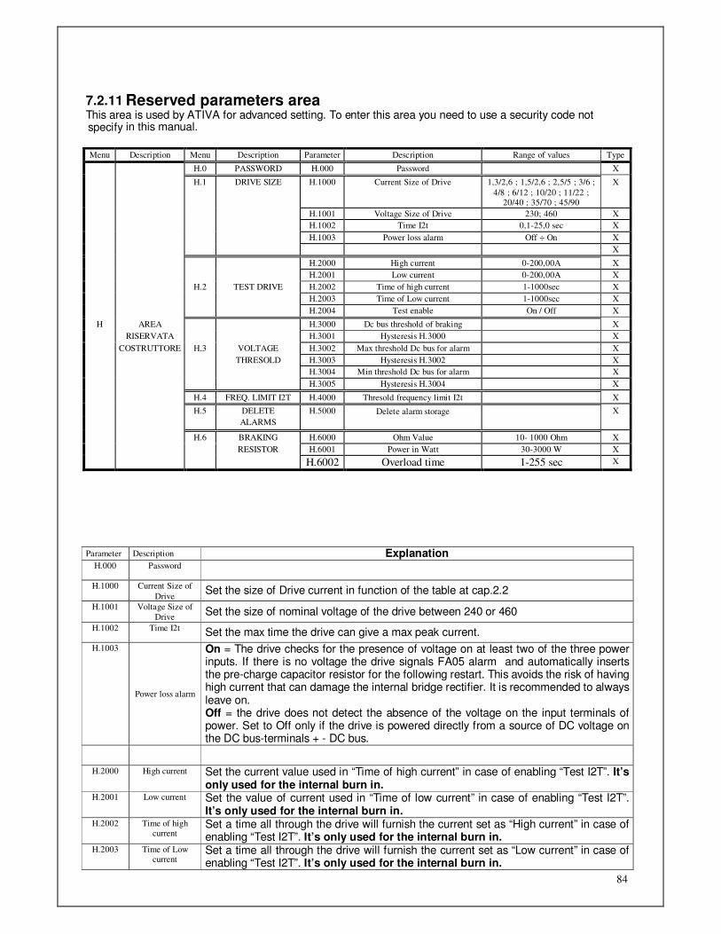
84
7.2.11 Reserved parameters area This area is used by ATIVA for advanced setting. To enter this area you need to use a security code not specify in this manual.
Menu Description Menu Description Parameter Description Range of values Type
H.0 PASSWORD H.000 Password X
H.1 DRIVE SIZE H.1000 Current Size of Drive 1,3/2,6 ; 1,5/2,6 ; 2,5/5 ; 3/6 ;
4/8 ; 6/12 ; 10/20 ; 11/22 ; 20/40 ; 35/70 ; 45/90
X
H.1001 Voltage Size of Drive 230; 460 X
H.1002 Time I2t 0,1-25,0 sec X
H.1003 Power loss alarm Off ÷ On X
X
H.2000 High current 0-200,00A X
H.2001 Low current 0-200,00A X
H.2 TEST DRIVE H.2002 Time of high current 1-1000sec X
H.2003 Time of Low current 1-1000sec X
H.2004 Test enable On / Off X
H AREA H.3000 Dc bus threshold of braking X
RISERVATA H.3001 Hysteresis H.3000 X
COSTRUTTORE H.3 VOLTAGE H.3002 Max threshold Dc bus for alarm X
THRESOLD H.3003 Hysteresis H.3002 X
H.3004 Min threshold Dc bus for alarm X
H.3005 Hysteresis H.3004 X
H.4 FREQ. LIMIT I2T H.4000 Thresold frequency limit I2t X
H.5 DELETE H.5000 Delete alarm storage X
ALARMS
H.6 BRAKING H.6000 Ohm Value 10- 1000 Ohm X
RESISTOR H.6001 Power in Watt 30-3000 W X
H.6002 Overload time 1-255 sec X
Parameter Description Explanation
H.000 Password
H.1000 Current Size of
Drive Set the size of Drive current in function of the table at cap.2.2
H.1001 Voltage Size of
Drive Set the size of nominal voltage of the drive between 240 or 460
H.1002 Time I2t Set the max time the drive can give a max peak current.
H.1003
Power loss alarm
On = The drive checks for the presence of voltage on at least two of the three power inputs. If there is no voltage the drive signals FA05 alarm and automatically inserts the pre-charge capacitor resistor for the following restart. This avoids the risk of having high current that can damage the internal bridge rectifier. It is recommended to always leave on. Off = the drive does not detect the absence of the voltage on the input terminals of power. Set to Off only if the drive is powered directly from a source of DC voltage on the DC bus-terminals + - DC bus.
H.2000 High current Set the current value used in “Time of high current” in case of enabling “Test I2T”. It’s only used for the internal burn in.
H.2001 Low current Set the value of current used in “Time of low current” in case of enabling “Test I2T”. It’s only used for the internal burn in.
H.2002 Time of high current
Set a time all through the drive will furnish the current set as “High current” in case of enabling “Test I2T”. It’s only used for the internal burn in.
H.2003 Time of Low current
Set a time all through the drive will furnish the current set as “Low current” in case of enabling “Test I2T”. It’s only used for the internal burn in.
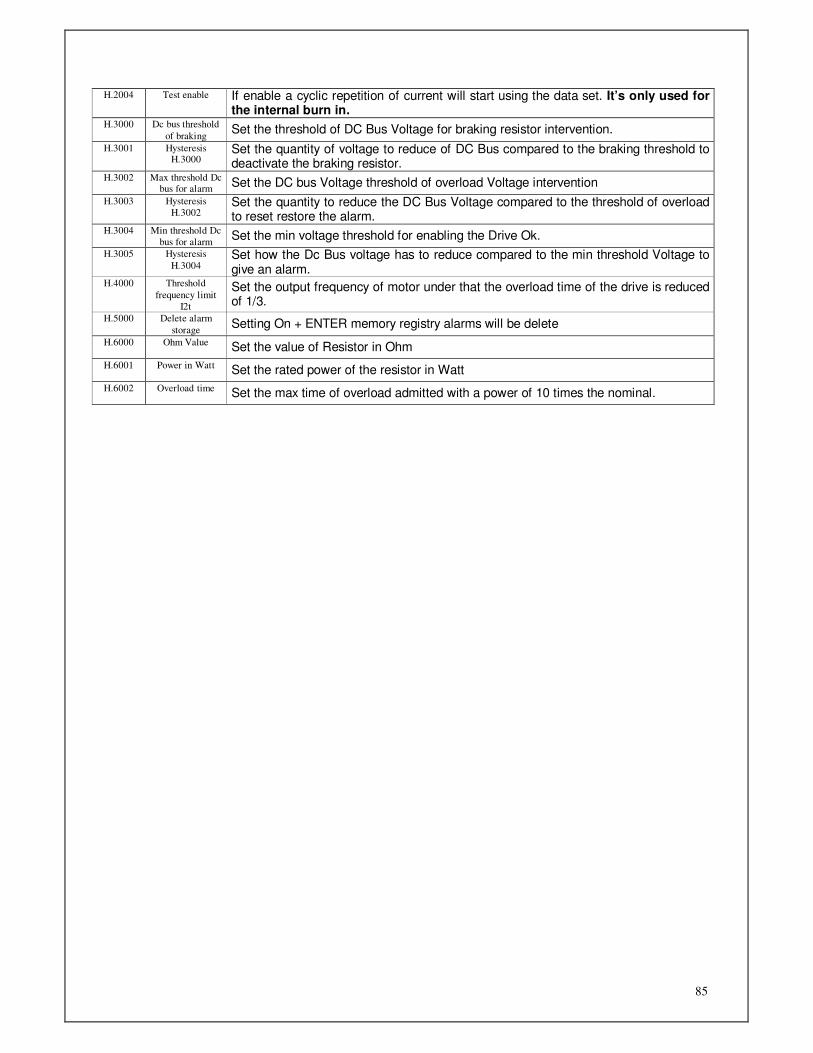
85
H.2004 Test enable If enable a cyclic repetition of current will start using the data set. It’s only used for the internal burn in.
H.3000 Dc bus threshold
of braking Set the threshold of DC Bus Voltage for braking resistor intervention.
H.3001 Hysteresis H.3000
Set the quantity of voltage to reduce of DC Bus compared to the braking threshold to deactivate the braking resistor.
H.3002 Max threshold Dc bus for alarm
Set the DC bus Voltage threshold of overload Voltage intervention
H.3003 Hysteresis
H.3002 Set the quantity to reduce the DC Bus Voltage compared to the threshold of overload to reset restore the alarm.
H.3004 Min threshold Dc
bus for alarm Set the min voltage threshold for enabling the Drive Ok.
H.3005 Hysteresis
H.3004 Set how the Dc Bus voltage has to reduce compared to the min threshold Voltage to give an alarm.
H.4000 Threshold
frequency limit
I2t
Set the output frequency of motor under that the overload time of the drive is reduced of 1/3.
H.5000 Delete alarm
storage Setting On + ENTER memory registry alarms will be delete
H.6000 Ohm Value Set the value of Resistor in Ohm
H.6001 Power in Watt Set the rated power of the resistor in Watt
H.6002 Overload time Set the max time of overload admitted with a power of 10 times the nominal.

86
8. Start up and adjustment
8.1 Preliminary controls
After a correct wiring, give supply voltage to the power inputs L1,L2,L3. Go to parameters m.xxxx = “Data Motor” and verify the concordance between motor data plate and data
set on the drive.(the value of stall current has to be set at the same value of the rated current). Go to parameters t.xxxx=”Control type” and choose the work modality and the references requested. Go to parameters i.xxxx =” Digital inputs” and enable the possible logical input used in the application. Go to parameters o.xxxx “Analog Out” to set the possible analog output needed. If simulated encoder is used go to parameters s.xxxx “Advanced set-up” and set the encoder resolution
wanted (s.3000). Set the max speed limit for the intervention of the relative alarms (s.5000) Set the max limit of current suppliable (% of rated current of the motor: s.5001) Verify that no possibility of damage may occur to person or material then activate the start through input
25 of J5. In presence of speed ref, the motor start to run at the speed set as soon as the “start-stop” input is enable in input12 of J5
Set gains KP, KI, KD in “advanced set-up” accordingly to the application. High values make the drive quicker. Values too much high can cause motor vibration.
If motor doesn’t start verify the correct assignment of speed reference and state of the eventual logic input enabled.(stop emerg. stop line; ref1/2) Besides if the motor is furnished by a magnetic brake, verify that is deactivated.
8.2 Motor Autotuning
With this procedure the DGM calculate automatically the number of poles of the motor and the phase displacement between resolver and motor. Before starting this procedure is useful to set correctly the max and rated current data of the motor and besides it’s necessary that motor will be detached from the load. To launch the procedure of auto timing it’s necessary: 1) To be in Stop 2) To go to area parameters“m.2003” (See cap.7.2.2). 3) Press ENTER to enter this parameter
4) Press ↑ to set “On” 5) Press ENTER At this point if the wiring of the cables is correct the motor runs a complete turn CW, then stops and after a few seconds on the display appear the message “Done” that indicate the end of the procedure.
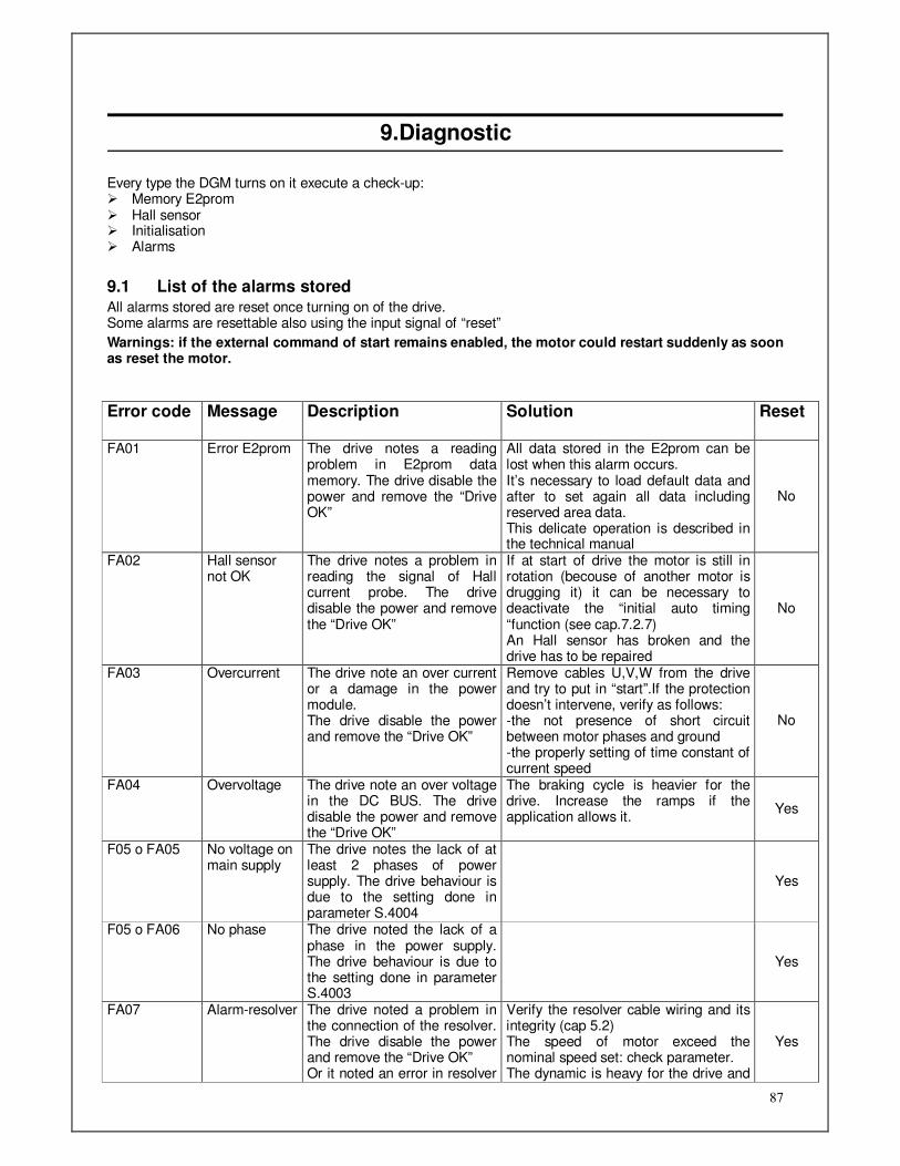
87
9.Diagnostic
Every type the DGM turns on it execute a check-up: Memory E2prom Hall sensor Initialisation Alarms
9.1 List of the alarms stored
All alarms stored are reset once turning on of the drive. Some alarms are resettable also using the input signal of “reset”
Warnings: if the external command of start remains enabled, the motor could restart suddenly as soon as reset the motor.
Error code Message Description Solution Reset
FA01 Error E2prom The drive notes a reading problem in E2prom data memory. The drive disable the power and remove the “Drive OK”
All data stored in the E2prom can be lost when this alarm occurs. It’s necessary to load default data and after to set again all data including reserved area data. This delicate operation is described in the technical manual
No
FA02 Hall sensor not OK
The drive notes a problem in reading the signal of Hall current probe. The drive disable the power and remove the “Drive OK”
If at start of drive the motor is still in rotation (becouse of another motor is drugging it) it can be necessary to deactivate the “initial auto timing “function (see cap.7.2.7) An Hall sensor has broken and the drive has to be repaired
No
FA03 Overcurrent The drive note an over current or a damage in the power module. The drive disable the power and remove the “Drive OK”
Remove cables U,V,W from the drive and try to put in “start”.If the protection doesn’t intervene, verify as follows: -the not presence of short circuit between motor phases and ground -the properly setting of time constant of current speed
No
FA04 Overvoltage The drive note an over voltage in the DC BUS. The drive disable the power and remove the “Drive OK”
The braking cycle is heavier for the drive. Increase the ramps if the application allows it.
Yes
F05 o FA05 No voltage on main supply
The drive notes the lack of at least 2 phases of power supply. The drive behaviour is due to the setting done in parameter S.4004
Yes
F05 o FA06 No phase The drive noted the lack of a phase in the power supply. The drive behaviour is due to the setting done in parameter S.4003
Yes
FA07 Alarm-resolver The drive noted a problem in the connection of the resolver. The drive disable the power and remove the “Drive OK” Or it noted an error in resolver
Verify the resolver cable wiring and its integrity (cap 5.2) The speed of motor exceed the nominal speed set: check parameter. The dynamic is heavy for the drive and
Yes

88
tracking it’s not able to follow the motor position. F08 Secure Power
Disable (SPD) SPD safety circuit intervention: the external power supply contact of the safety circuit (SPD) is open.
Close the contact and reset the alarms. In case of fault of the SPD safety circuit, after reset the alarms a new alarm will appear FA18 or FA23
Yes
FA09 Alarm Overtemp. Motor
The thermal probe of the motor has got an over temperature. The drive disable the power and the “drive Ok”
Verify that the cycle of work will be not heavy for the type of motor chosen. Verify the correct wiring of the PTC probe. (Cap 5.2)
Yes
FA10 Braking resistor alarm
The theoretical thermal calculus of the braking resistor has revealed an over warming
The number of cycle of braking is heavy for the resistor chosen. Reduce heaviness of work and put a suited resistor.
FA11 Alarm no voltage 24V
The lack of aux voltage of 24Vdc on pin 39 The drive disable the power and the “drive Ok”
Give a voltage of 24Vdc between terminal 39 (+24) and 10 (com) of J5. Voltage can be taken from terminal 24 (+24) and 9 (com) of J5. It is possible disable this alarm with parameterr S.4008
Yes
FA12 Under voltage alarm
The drive is supplied by an auxiliary source. There is a lack of RST power voltage to the terminals. The drive disable the power and the “drive Ok”
Automatic reactivation when power voltage return.
Yes
F13 o FA13 Position error alarm
Error in “Electronic gearbox” or “position control”. The error is due to a big difference between reference and reaction. It can be an alarm or a warning depending from setting of parameter S.1500
Correct the parameter of speed PID and the position or reduce the dynamic. Increase the windows errror in parameter S.1501. Yes
FA14 Alarm Home position
During the cycle positioning Home position has not found
Execute an home position
F15 Warning I2t Drive
The drive supplies such a high current that the theoretical temperature of the drive has exceeded the max threshold of the drive. The drive doesn’t stop to work but it begins to furnish a max current equal to the rated of the drive. In this case the drive show the led I2t and activates the output 24V “I2t”.
Verify the work cycle is not heavy for the type of drive. Verify that the parameter as constant of speed loop is not too much extreme. Increase ramp if the application allows. In the case of the first commissioning the drive, verify the correct correlation between the UVW motor and the relative phases of the drive.
Yes
F16 Warning I2t motor
The drive supplies such a high current that the theoretical temperature has exceeded the delta T of 100°C . From this point the drive limits the max current supplied to the rated of the motor.
Verify the work cycle is not heavy for the type of drive. Verify that the parameter as constant of speed loop is not too much extreme. Increase ramp if the application allows. Verify that the “Time I2T” value on special motor parameter is set at a correct value compared to motor
Yes
F17 Warning Overspeed
Advise that the max speed set on parameter “limit speed” has been exceeded. The drive still works correctly.
Verify that parameter “speed limit” is at least 10% bigger than the max speed reachable to the motor. Verify that time constant set for the speed loop will not generate a higher overshoot of speed (overspeed)
Yes
FA18 SPD Failure Optoinsulator1
The optoinsulator 1 of the SPD safety circuit is damaged
It’s necessary to repair the drive No
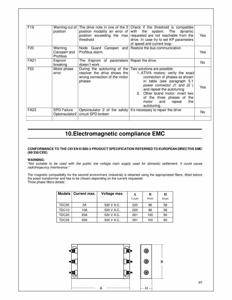
89
F19 Warning out of position
The drive note in one of the 3 position modality an error of position exceeding the max threshold
Check if the threshold is compatible with the system. The dynamic requested are not reachable from the drive. In case try to set KP parameters of speed and current loop.
Yes
F20 Warning Canopen and Profibus
Node Guard Canopen and Profibus alarm.
Restore the bus communication Yes
FA21 Eeprom breaking
The Eeprom of parameters doesn’t work
Repair the drive. No
F22 Motor phase error
During the autotuning of the resolver the drive shows the wrong connection of the motor phases
Two solutions are possible: 1. ATIVA motors: verify the exact
connection of phases as shown in table (see paragraph 5.1 power connector J1 and J2 ) and repeat the autotuning
2. Other brand motor: invert two of the three phases of the motor and repeat the autotuning.
Yes
FA23 SPD Failure Optoinsulator2
Optoinsulator 2 of the safety circuit SPD broken
It’s necessary to repair the drive No
10.Electromagnetic compliance EMC
CONFORMANCE TO THE CEI EN 61800-3 PRODUCT SPECIFICATION REFERRED TO EUROPEAN DIRECTIVE EMC (89/336/CEE) WARNING: “Not suitable to be used with the public low voltage main supply used for domestic settlement. It could cause radiofreqeuncy interference.” The magnetic compatibility for the second environment (industrial) is obtained using the appropriated filters, fitted before the poser transformer and has to be chosen depending on the current requested. Three phase filters details:
Models Current max. Voltage max. A Length
B Width
H Height
TDC05 5A 520 V A.C. 220 86 58
TDC10 10A 520 V A.C. 220 86 58
TDC20 20A 520 V A.C. 261 100 90
TDC35 35A 520 V A.C. 261 100 90
A H
B

90
www.ativa-automacao.com.br
Campinas, SP - Alphaville - (19) 3262 1677