PSA - Azione Incendio: caratteristiche del fenomeno fisico - Gentili
Upload
franco-bontempi-org-didatticaCategory
view
702download
0
Approccio sistemico per la sicurezza
delle gallerie in caso di incendio
e problemi strutturali specifici
Prof. Ing. Franco Bontempi
Ordinario di Tecnica delle Costruzioni
Facolta’ di Ingegneria Civile e Industriale
Universita’ degli Studi di Roma La Sapienza
Corso di
PROGETTAZIONE STRUTTURALE ANTINCENDIO
A.A. 2015/16
FB - Dicembre 2015 Progettazione Strutturale
Antincendio
1
Scopo della presentazione
• Far vedere gli aspetti piu’ generali della
progettazione strutturale antincendio:
Complessita’ del problema;
Approccio sistemico;
Natura accidentale dell’azione incendio;
Progettazione prestazionale/prescrittiva;
Aspetti specifici delle gallerie stradali.
FB - Dicembre 2015 Progettazione Strutturale
Antincendio
2

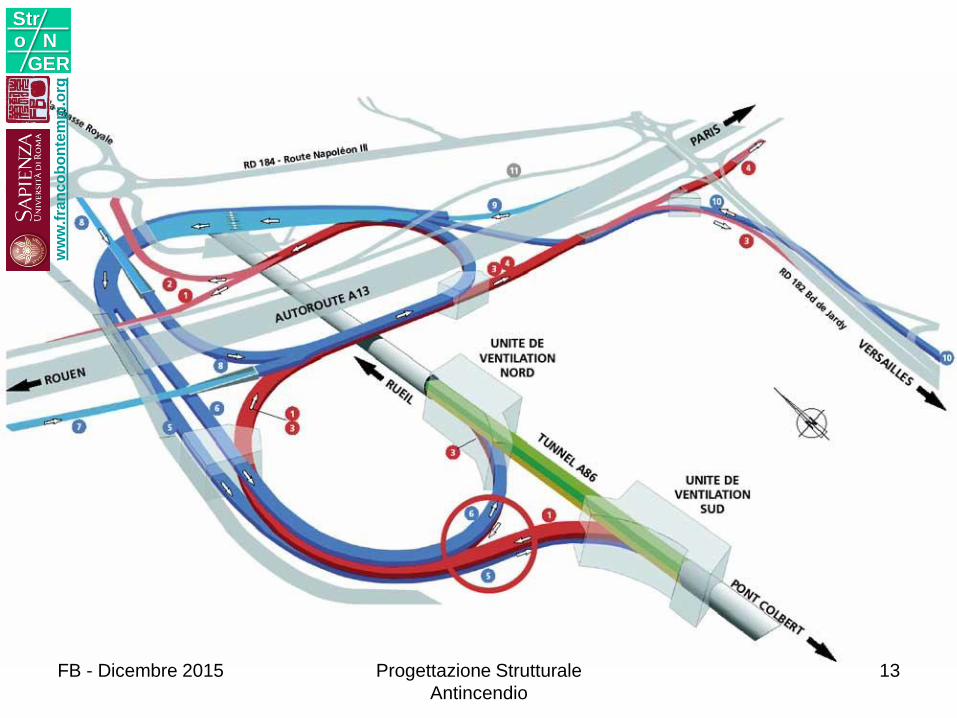
OGGETTOCaratteristiche delle gallerie
Geometrie
Impianti
1w
ww
.fra
nc
ob
on
tem
pi.o
rg
Stro N
GER
FB - Dicembre 2015 Progettazione Strutturale
Antincendio
3
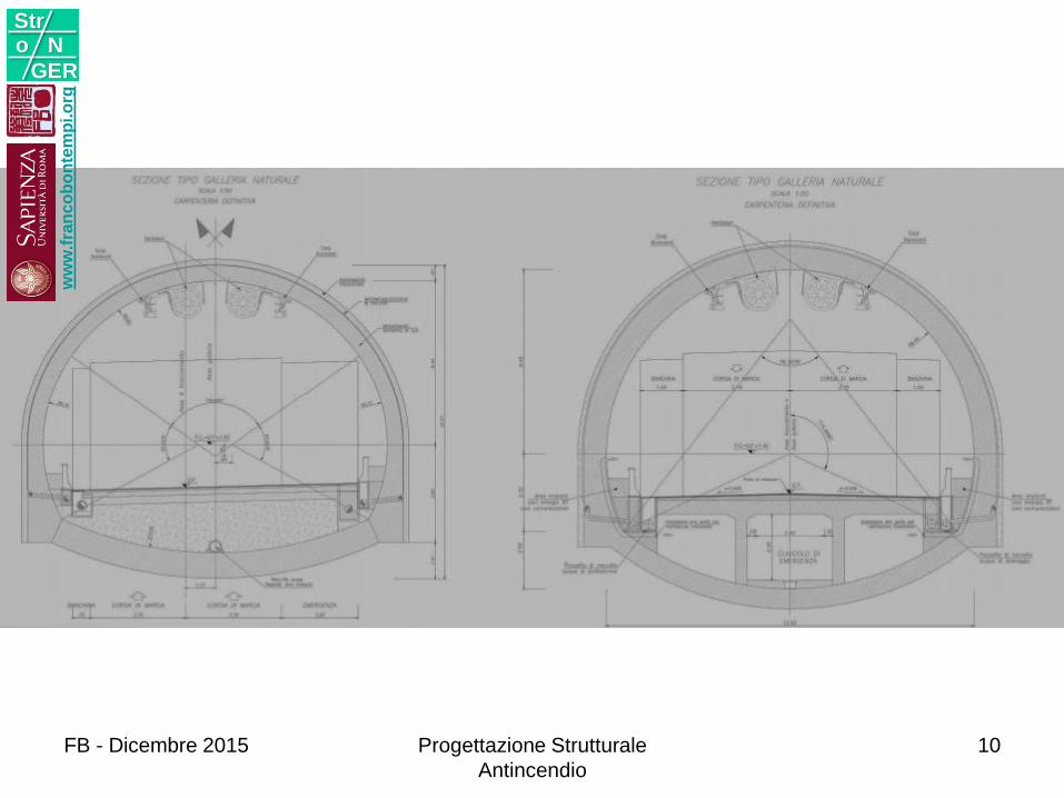
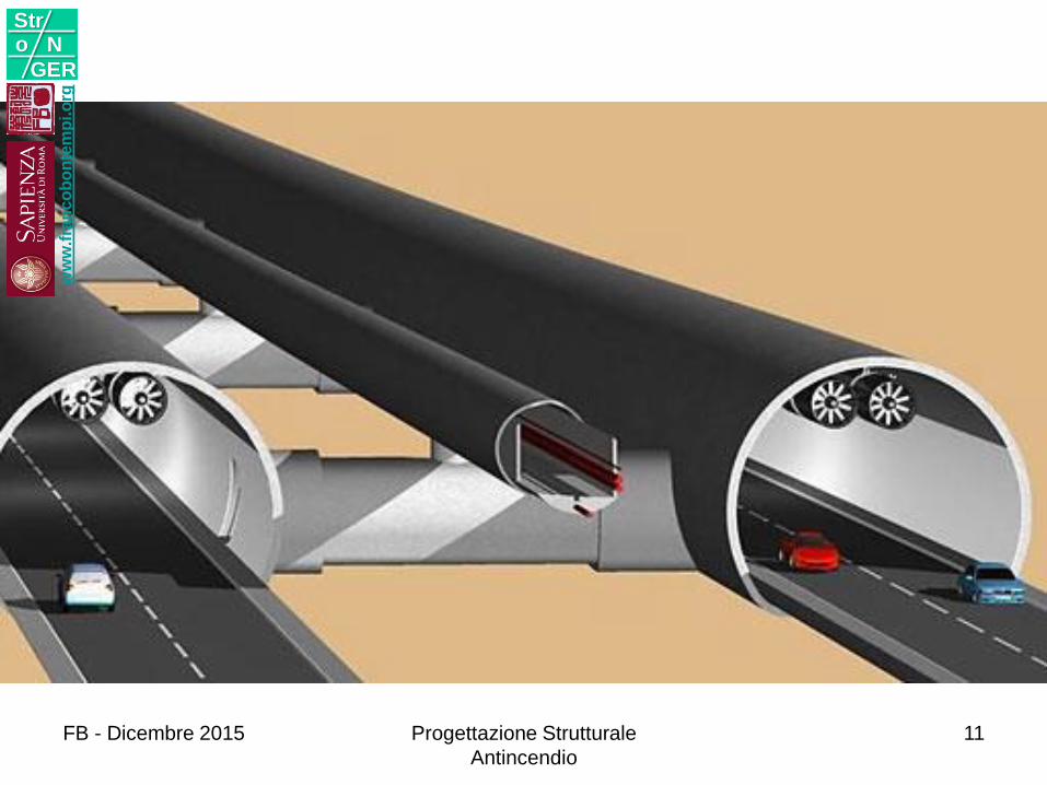
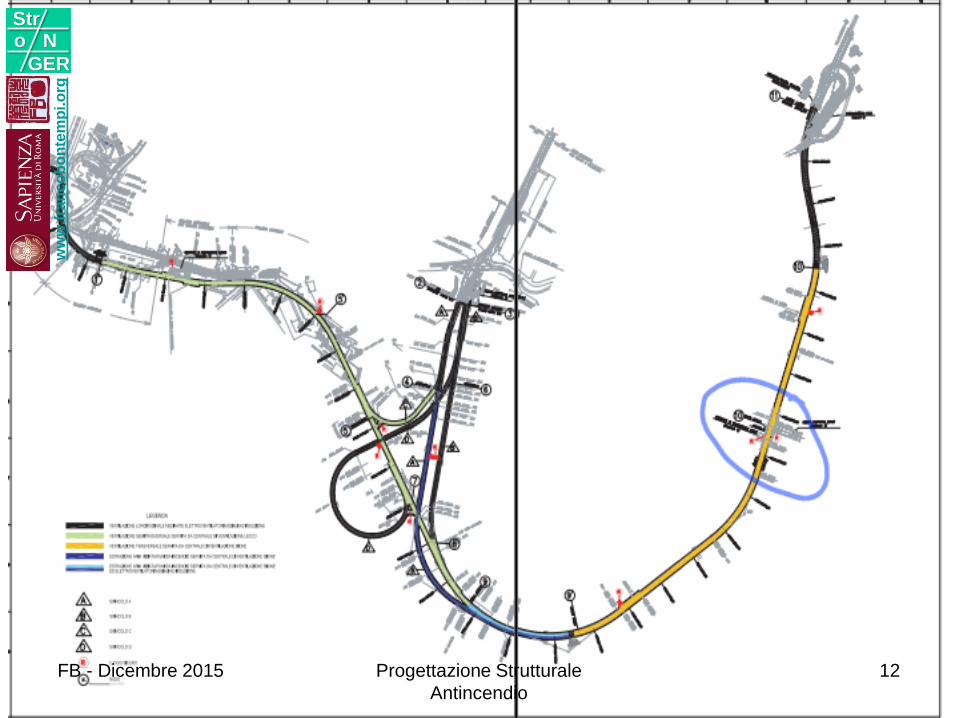
GEOMETRIE
ww
w.f
ran
co
bo
nte
mp
i.o
rg
Stro N
GER
FB - Dicembre 2015 Progettazione Strutturale
Antincendio
4
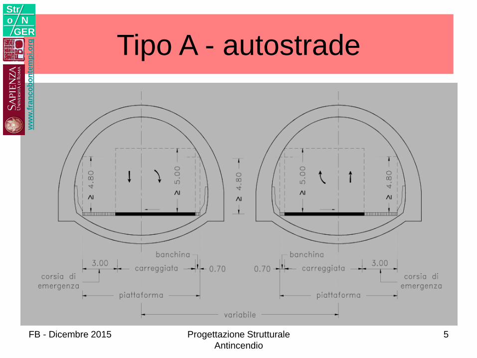
Tipo A - autostrade w
ww
.fra
nc
ob
on
tem
pi.o
rg
Stro N
GER
FB - Dicembre 2015 Progettazione Strutturale
Antincendio
5
ww
w.f
ran
co
bo
nte
mp
i.o
rg
Stro N
GER
FB - Dicembre 2015 Progettazione Strutturale
Antincendio
6
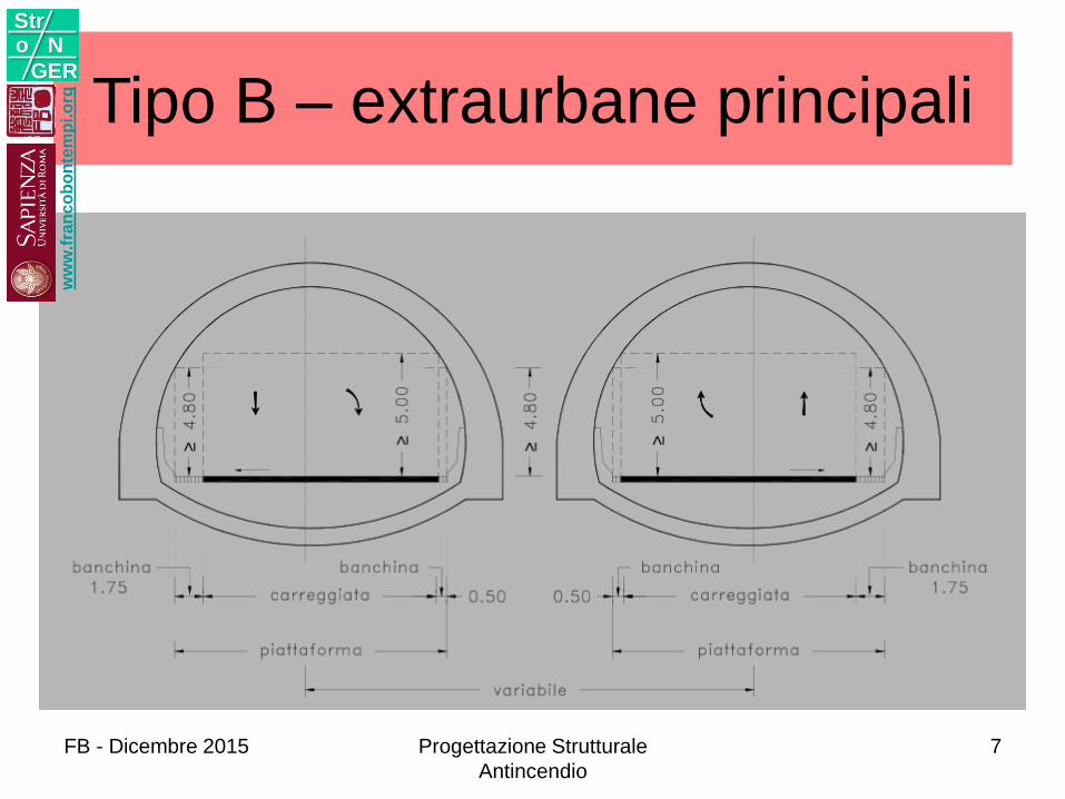
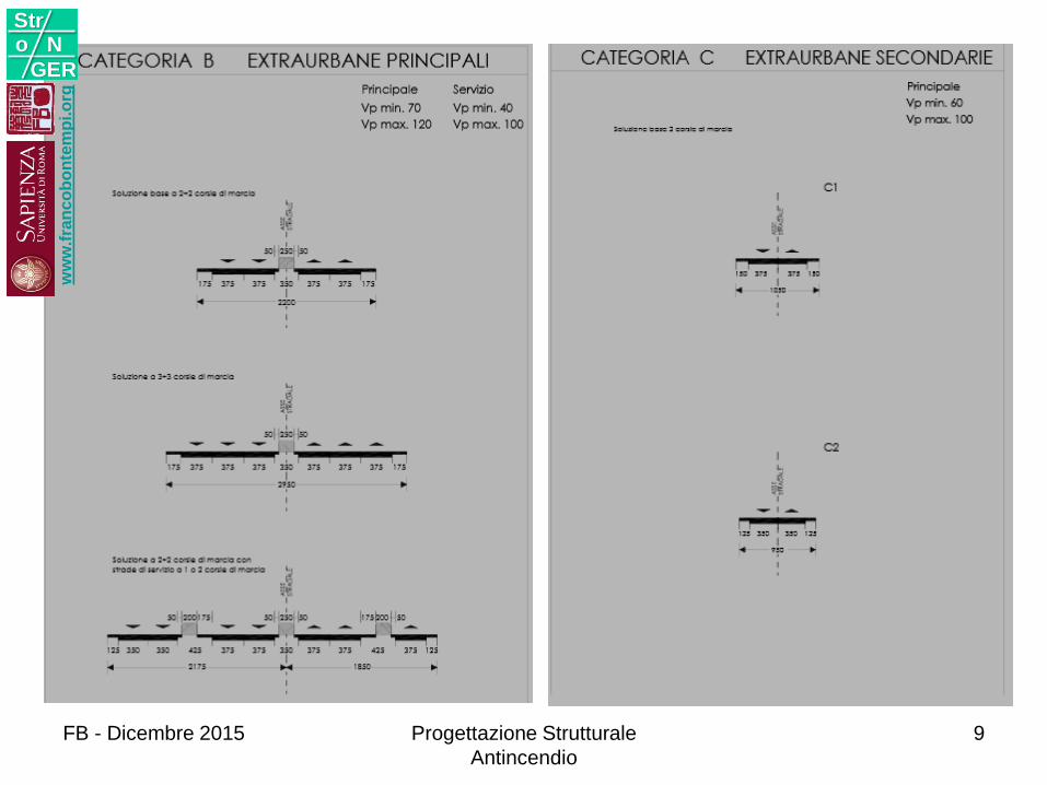
Tipo B – extraurbane principaliw
ww
.fra
nc
ob
on
tem
pi.o
rg
Stro N
GER
FB - Dicembre 2015 Progettazione Strutturale
Antincendio
7
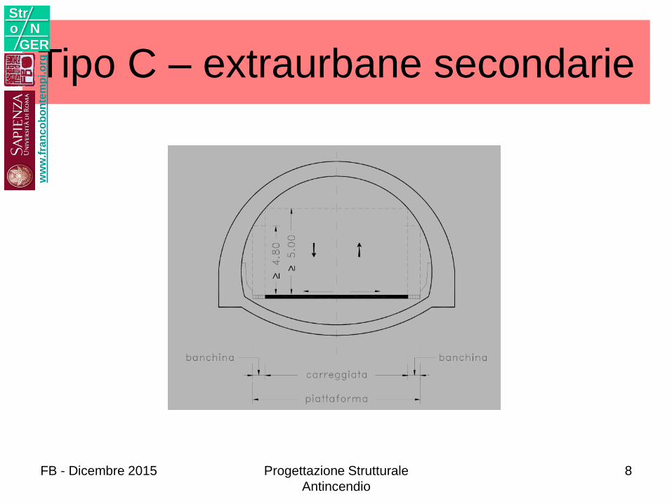
Tipo C – extraurbane secondariew
ww
.fra
nc
ob
on
tem
pi.o
rg
Stro N
GER
FB - Dicembre 2015 Progettazione Strutturale
Antincendio
8
ww
w.f
ran
co
bo
nte
mp
i.o
rg
Stro N
GER
FB - Dicembre 2015 Progettazione Strutturale
Antincendio
9
ww
w.f
ran
co
bo
nte
mp
i.o
rg
Stro N
GER
FB - Dicembre 2015 Progettazione Strutturale
Antincendio
10
ww
w.f
ran
co
bo
nte
mp
i.o
rg
Stro N
GER
FB - Dicembre 2015 Progettazione Strutturale
Antincendio
11
ww
w.f
ran
co
bo
nte
mp
i.o
rg
Stro N
GER
FB - Dicembre 2015 Progettazione Strutturale
Antincendio
12
ww
w.f
ran
co
bo
nte
mp
i.o
rg
Stro N
GER
FB - Dicembre 2015 Progettazione Strutturale
Antincendio
13
ww
w.f
ran
co
bo
nte
mp
i.o
rg
Stro N
GER
FB - Dicembre 2015 Progettazione Strutturale
Antincendio
14
ww
w.f
ran
co
bo
nte
mp
i.o
rg
Stro N
GER
FB - Dicembre 2015 Progettazione Strutturale
Antincendio
15
ww
w.f
ran
co
bo
nte
mp
i.o
rg
Stro N
GER
FB - Dicembre 2015 Progettazione Strutturale
Antincendio
16
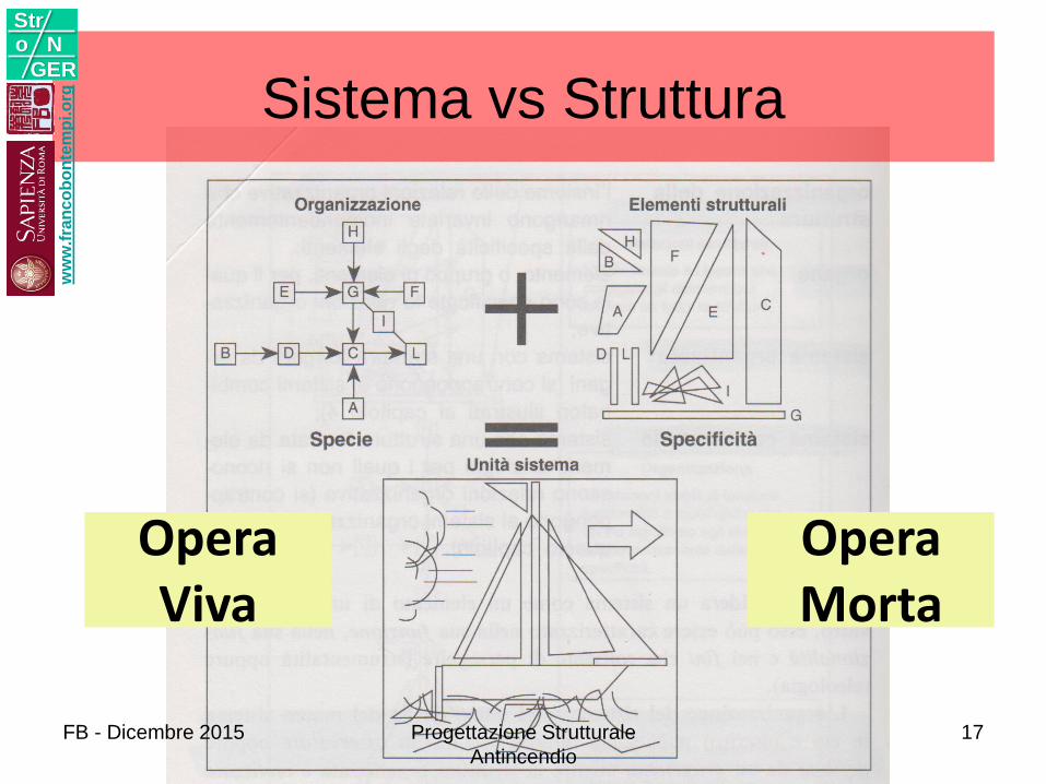
Sistema vs Strutturaw
ww
.fra
nc
ob
on
tem
pi.o
rg
Stro N
GER
OperaMorta
OperaViva
FB - Dicembre 2015 Progettazione Strutturale
Antincendio
17
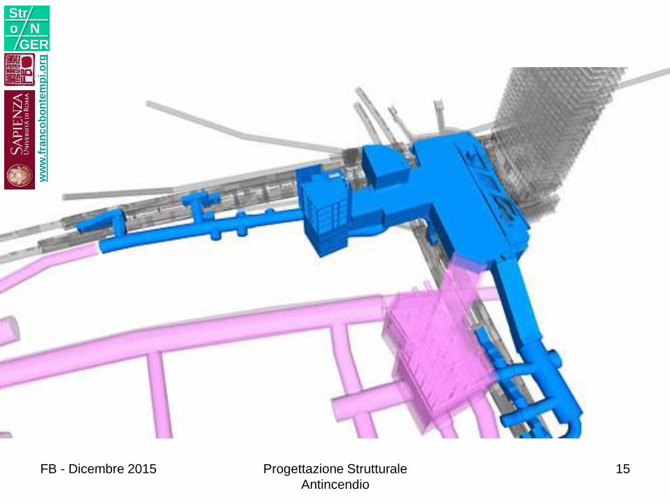
IMPIANTI VENTILAZIONE
ww
w.f
ran
co
bo
nte
mp
i.o
rg
Stro N
GER
FB - Dicembre 2015 Progettazione Strutturale
Antincendio
18
ww
w.f
ran
co
bo
nte
mp
i.o
rg
Stro N
GER
FB - Dicembre 2015 Progettazione Strutturale
Antincendio
19
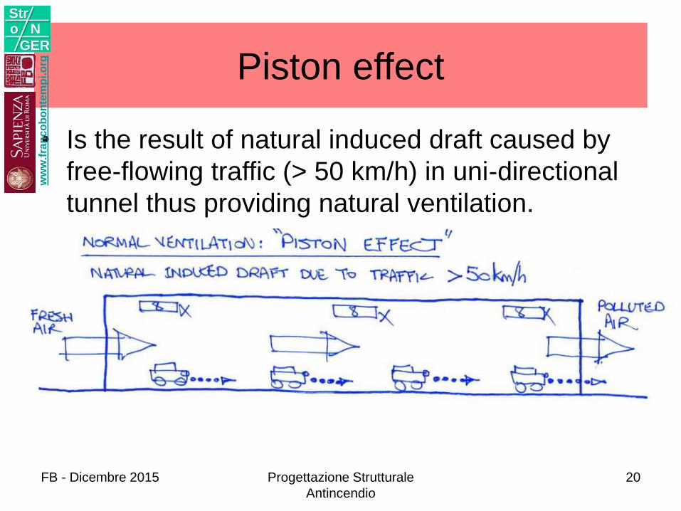
Piston effect
• Is the result of natural induced draft caused by
free-flowing traffic (> 50 km/h) in uni-directional
tunnel thus providing natural ventilation.
ww
w.f
ran
co
bo
nte
mp
i.o
rg
Stro N
GER
FB - Dicembre 2015 Progettazione Strutturale
Antincendio
20
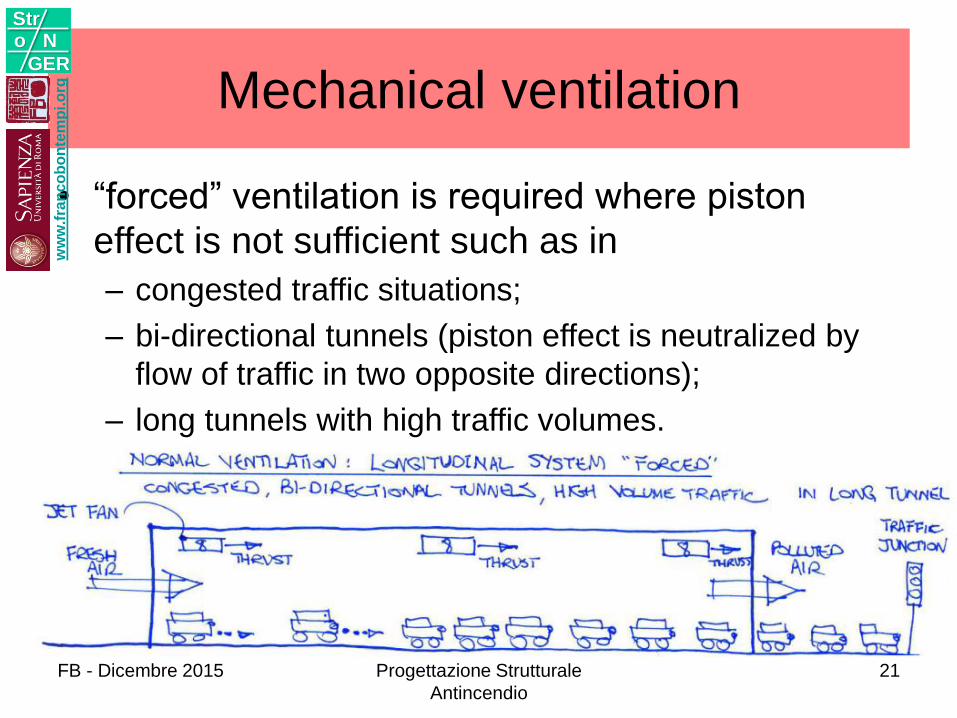
Mechanical ventilation
• “forced” ventilation is required where piston
effect is not sufficient such as in
– congested traffic situations;
– bi-directional tunnels (piston effect is neutralized by
flow of traffic in two opposite directions);
– long tunnels with high traffic volumes.
ww
w.f
ran
co
bo
nte
mp
i.o
rg
Stro N
GER
FB - Dicembre 2015 Progettazione Strutturale
Antincendio
21
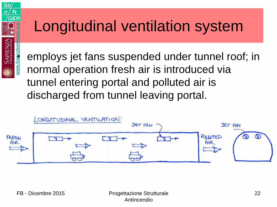
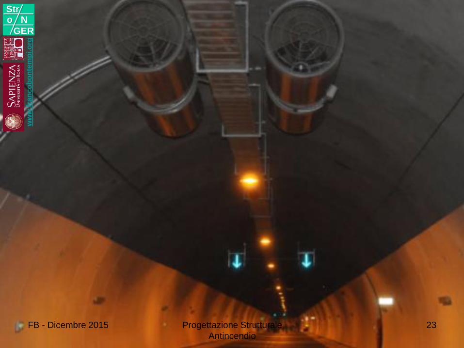
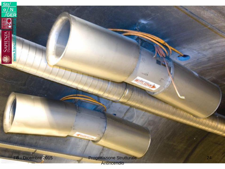
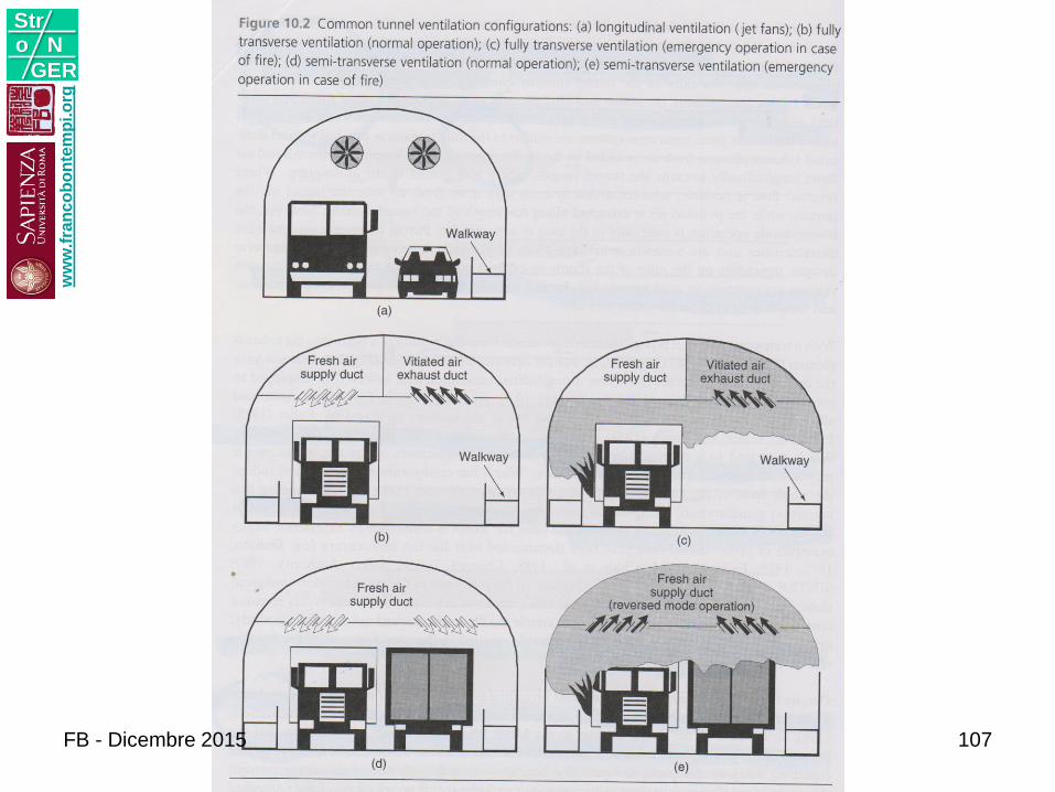
Longitudinal ventilation system
• employs jet fans suspended under tunnel roof; in
normal operation fresh air is introduced via
tunnel entering portal and polluted air is
discharged from tunnel leaving portal.
ww
w.f
ran
co
bo
nte
mp
i.o
rg
Stro N
GER
FB - Dicembre 2015 Progettazione Strutturale
Antincendio
22
ww
w.f
ran
co
bo
nte
mp
i.o
rg
Stro N
GER
FB - Dicembre 2015 Progettazione Strutturale
Antincendio
23
ww
w.f
ran
co
bo
nte
mp
i.o
rg
Stro N
GER
FB - Dicembre 2015 Progettazione Strutturale
Antincendio
24
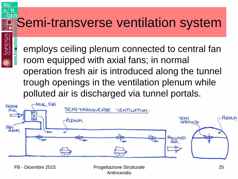
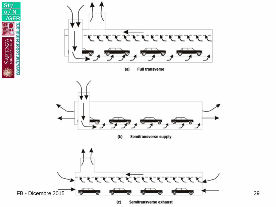
Semi-transverse ventilation system
• employs ceiling plenum connected to central fan
room equipped with axial fans; in normal
operation fresh air is introduced along the tunnel
trough openings in the ventilation plenum while
polluted air is discharged via tunnel portals.
ww
w.f
ran
co
bo
nte
mp
i.o
rg
Stro N
GER
FB - Dicembre 2015 Progettazione Strutturale
Antincendio
25
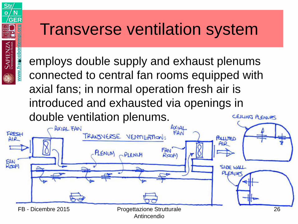
Transverse ventilation system
• employs double supply and exhaust plenums
connected to central fan rooms equipped with
axial fans; in normal operation fresh air is
introduced and exhausted via openings in
double ventilation plenums.
ww
w.f
ran
co
bo
nte
mp
i.o
rg
Stro N
GER
FB - Dicembre 2015 Progettazione Strutturale
Antincendio
26
ww
w.f
ran
co
bo
nte
mp
i.o
rg
Stro N
GER
FB - Dicembre 2015 Progettazione Strutturale
Antincendio
27
ww
w.f
ran
co
bo
nte
mp
i.o
rg
Stro N
GER
FB - Dicembre 2015 Progettazione Strutturale
Antincendio
28
ww
w.f
ran
co
bo
nte
mp
i.o
rg
Stro N
GER
FB - Dicembre 2015 29
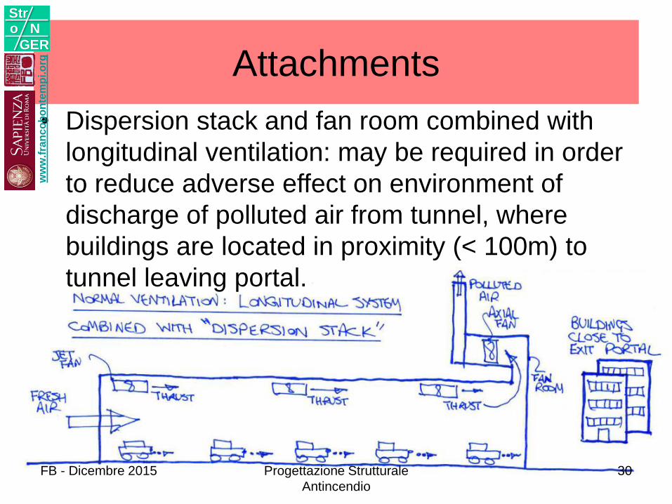
Attachments
• Dispersion stack and fan room combined with
longitudinal ventilation: may be required in order
to reduce adverse effect on environment of
discharge of polluted air from tunnel, where
buildings are located in proximity (< 100m) to
tunnel leaving portal.
ww
w.f
ran
co
bo
nte
mp
i.o
rg
Stro N
GER
FB - Dicembre 2015 Progettazione Strutturale
Antincendio
30
ww
w.f
ran
co
bo
nte
mp
i.o
rg
Stro N
GER
FB - Dicembre 2015 Progettazione Strutturale
Antincendio
31
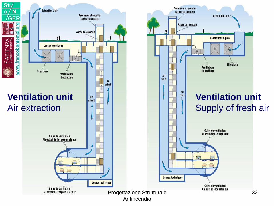
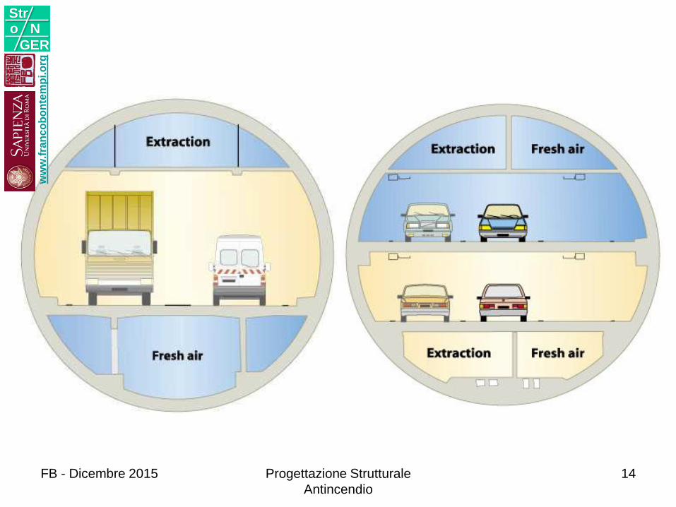
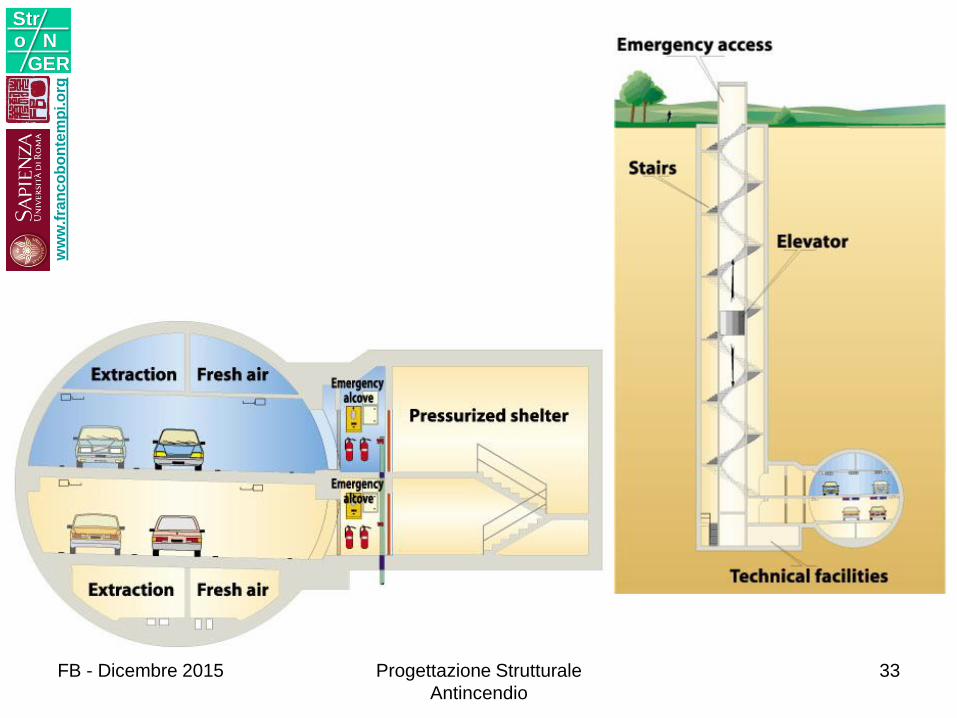
Ventilation unit
Air extraction
Ventilation unit
Supply of fresh air
ww
w.f
ran
co
bo
nte
mp
i.o
rg
Stro N
GER
Progettazione Strutturale
Antincendio
32
ww
w.f
ran
co
bo
nte
mp
i.o
rg
Stro N
GER
FB - Dicembre 2015 Progettazione Strutturale
Antincendio
33
COMPLESSITA’Approccio prestazionale
Modellazione
Sicurezza
2w
ww
.fra
nc
ob
on
tem
pi.o
rg
Stro N
GER
FB - Dicembre 2015 Progettazione Strutturale
Antincendio
34
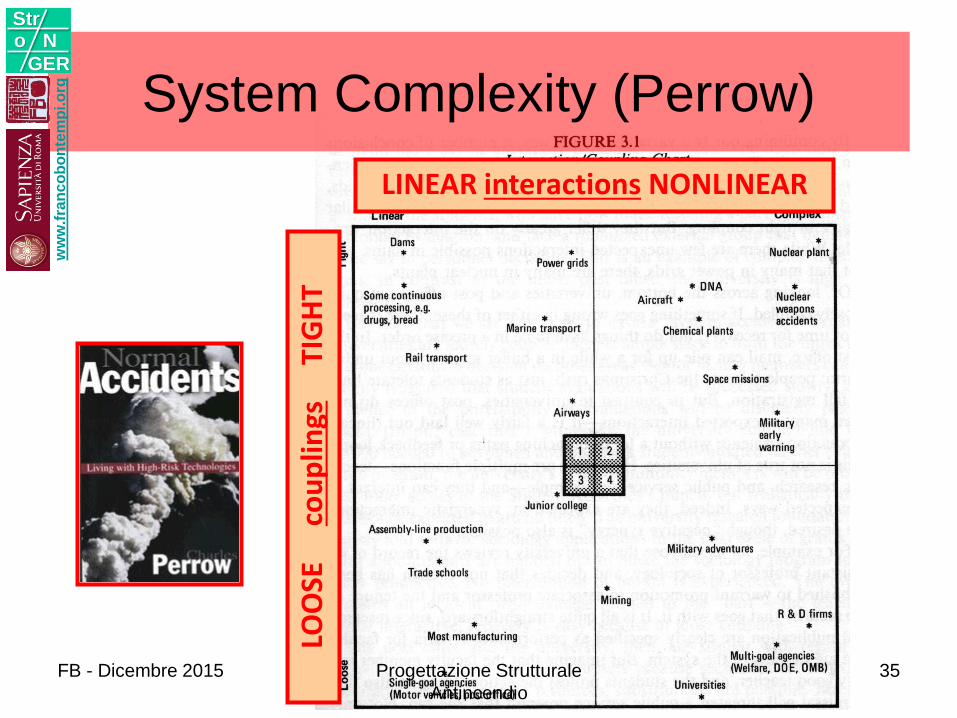
LOO
SE
co
up
lings
TIG
HT
LINEAR interactions NONLINEAR
System Complexity (Perrow)w
ww
.fra
nc
ob
on
tem
pi.o
rg
Stro N
GER
FB - Dicembre 2015 Progettazione Strutturale
Antincendio
35
APPROCCIO PRESTAZIONALE
ww
w.f
ran
co
bo
nte
mp
i.o
rg
Stro N
GER
FB - Dicembre 2015 Progettazione Strutturale
Antincendio
36
ww
w.f
ran
co
bo
nte
mp
i.o
rg
Stro N
GER
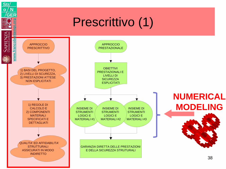
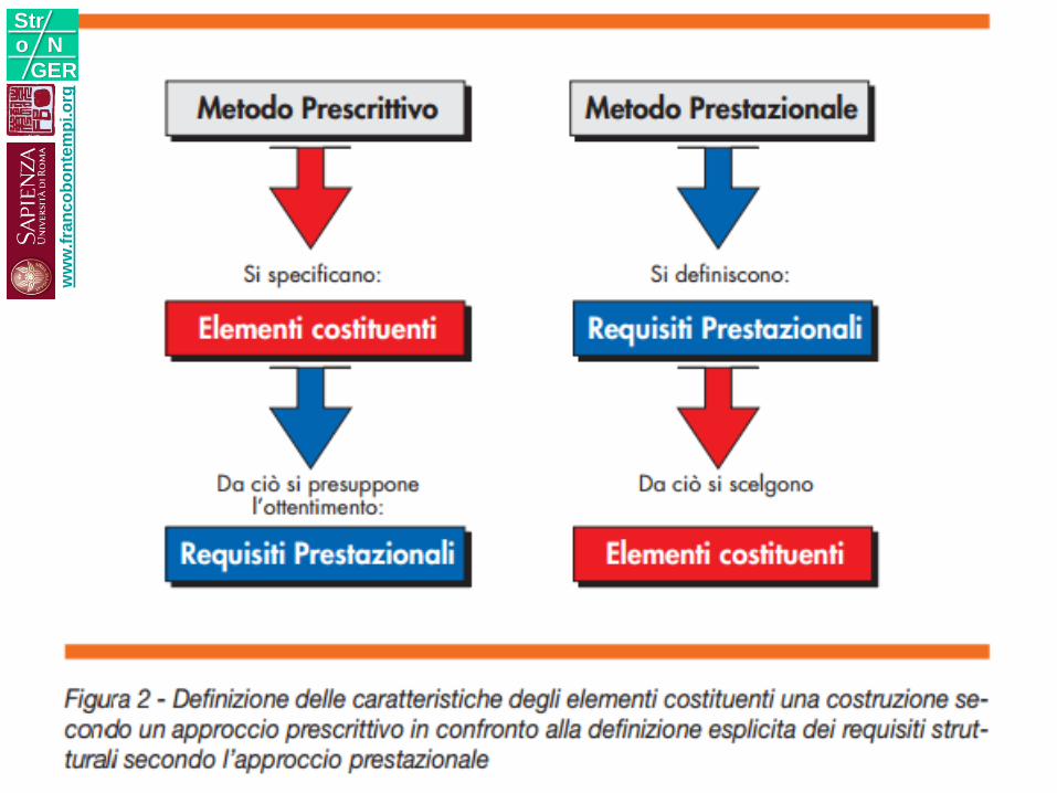
Prescrittivo (1)
APPROCCIO
PRESCRITTIVO
1) BASI DEL PROGETTO,
2) LIVELLI DI SCUREZZA,
3) PRESTAZIONI ATTESE
NON ESPLICITATI
1) REGOLE DI
CALCOLO E
2) COMPONENTI
MATERIALI
SPECIFICATI E
DETTAGLIATI
QUALITA' ED AFFIDABILITA'
STRUTTURALI
ASSICURATI IN MODO
INDIRETTO
GARANZIA DIRETTA DELLE PRESTAZIONI
E DELLA SICUREZZA STRUTURALI
INSIEME DI
STRUMENTI
LOGICI E
MATERIALI #3
INSIEME DI
STRUMENTI
LOGICI E
MATERIALI #1
INSIEME DI
STRUMENTI
LOGICI E
MATERIALI #2
OBIETTIVI
PRESTAZIONALI E
LIVELLI DI
SICUREZZA
ESPLICITATI
APPROCCIO
PRESTAZIONALE
NUMERICAL
MODELING
ww
w.f
ran
co
bo
nte
mp
i.o
rg
Stro N
GER
38
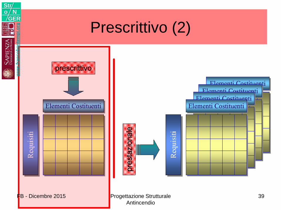
Prescrittivo (2)w
ww
.fra
nc
ob
on
tem
pi.o
rg
Stro N
GER
FB - Dicembre 2015 Progettazione Strutturale
Antincendio
39
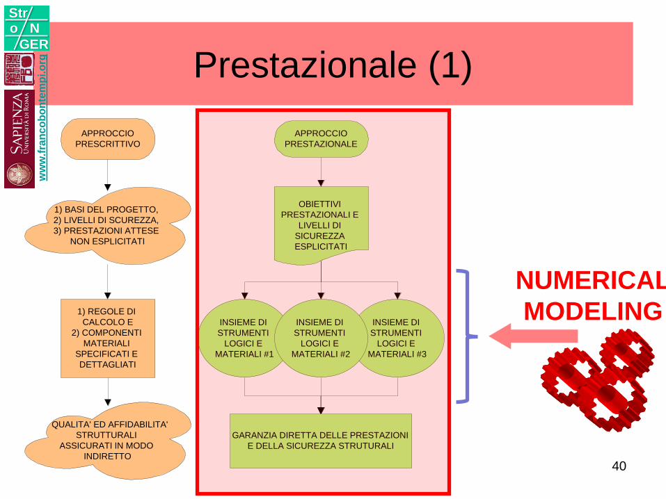
Prestazionale (1)
APPROCCIO
PRESCRITTIVO
1) BASI DEL PROGETTO,
2) LIVELLI DI SCUREZZA,
3) PRESTAZIONI ATTESE
NON ESPLICITATI
1) REGOLE DI
CALCOLO E
2) COMPONENTI
MATERIALI
SPECIFICATI E
DETTAGLIATI
QUALITA' ED AFFIDABILITA'
STRUTTURALI
ASSICURATI IN MODO
INDIRETTO
GARANZIA DIRETTA DELLE PRESTAZIONI
E DELLA SICUREZZA STRUTURALI
INSIEME DI
STRUMENTI
LOGICI E
MATERIALI #3
INSIEME DI
STRUMENTI
LOGICI E
MATERIALI #1
INSIEME DI
STRUMENTI
LOGICI E
MATERIALI #2
OBIETTIVI
PRESTAZIONALI E
LIVELLI DI
SICUREZZA
ESPLICITATI
APPROCCIO
PRESTAZIONALE
NUMERICAL
MODELING
ww
w.f
ran
co
bo
nte
mp
i.o
rg
Stro N
GER
40
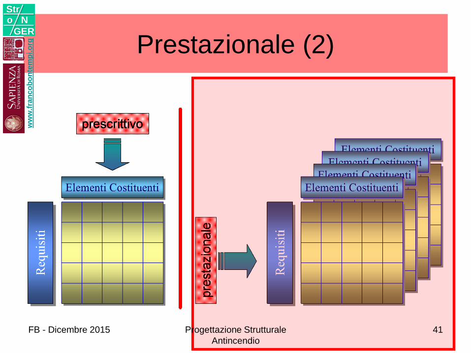
Prestazionale (2)w
ww
.fra
nc
ob
on
tem
pi.o
rg
Stro N
GER
FB - Dicembre 2015 Progettazione Strutturale
Antincendio
41
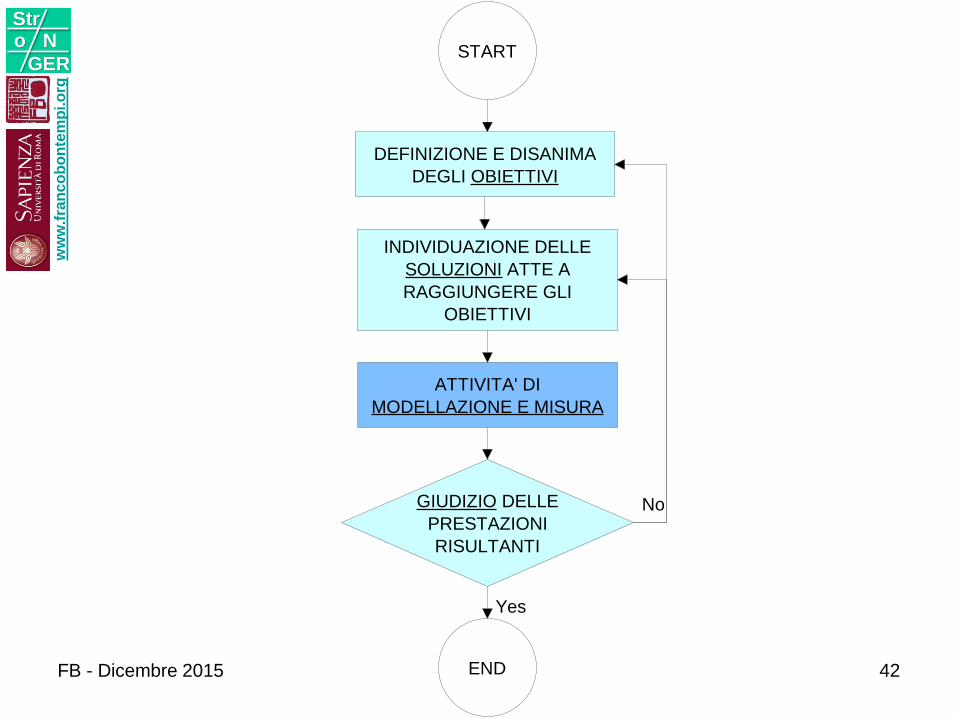
START
APPLICAZIONE
DI
REGOLE
PRESTABILITE
E
TECNICHE
PREDEFINITE
END
START
END
DEFINIZIONE E DISANIMA
DEGLI OBIETTIVI
INDIVIDUAZIONE DELLE
SOLUZIONI ATTE A
RAGGIUNGERE GLI
OBIETTIVI
ATTIVITA' DI
MODELLAZIONE E MISURA
GIUDIZIO DELLE
PRESTAZIONI
RISULTANTI
No
Yes
ww
w.f
ran
co
bo
nte
mp
i.o
rg
Stro N
GER
FB - Dicembre 2015 42
ww
w.f
ran
co
bo
nte
mp
i.o
rg
Stro N
GER
FB - Dicembre 2015 Progettazione Strutturale
Antincendio
43
ww
w.f
ran
co
bo
nte
mp
i.o
rg
Stro N
GER
FB - Dicembre 2015 Progettazione Strutturale
Antincendio
44
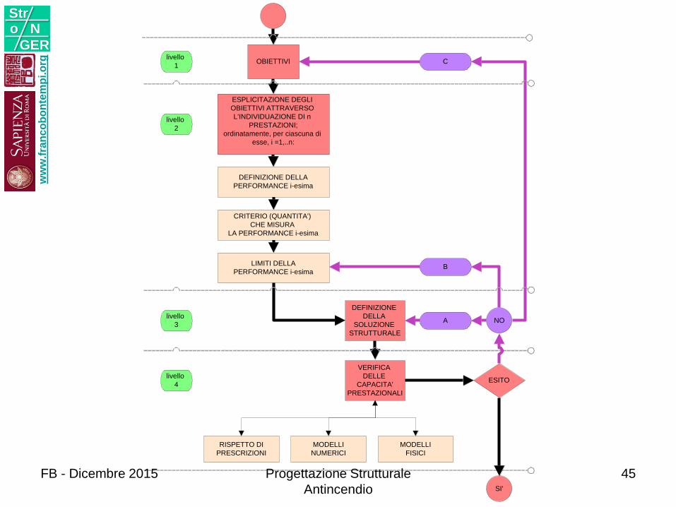
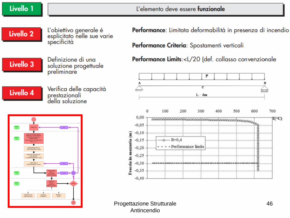
MODELLI
NUMERICI
MODELLI
FISICI
RISPETTO DI
PRESCRIZIONI
livello
1OBIETTIVI
livello
3
DEFINIZIONE
DELLA
SOLUZIONE
STRUTTURALE
livello
4
VERIFICA
DELLE
CAPACITA'
PRESTAZIONALI
LIMITI DELLA
PERFORMANCE i-esima
CRITERIO (QUANTITA')
CHE MISURA
LA PERFORMANCE i-esima
DEFINIZIONE DELLA
PERFORMANCE i-esima
livello
2
ESPLICITAZIONE DEGLI
OBIETTIVI ATTRAVERSO
L'INDIVIDUAZIONE DI n
PRESTAZIONI;
ordinatamente, per ciascuna di
esse, i =1,..n:
ESITO
NO
SI'
A
C
B
ww
w.f
ran
co
bo
nte
mp
i.o
rg
Stro N
GER
FB - Dicembre 2015 Progettazione Strutturale
Antincendio
45
MODELLI
NUMERICI
MODELLI
FISICI
RISPETTO DI
PRESCRIZIONI
livello
1OBIETTIVI
livello
3
DEFINIZIONE
DELLA
SOLUZIONE
STRUTTURALE
livello
4
VERIFICA
DELLE
CAPACITA'
PRESTAZIONALI
LIMITI DELLA
PERFORMANCE i-esima
CRITERIO (QUANTITA')
CHE MISURA
LA PERFORMANCE i-esima
DEFINIZIONE DELLA
PERFORMANCE i-esima
livello
2
ESPLICITAZIONE DEGLI
OBIETTIVI ATTRAVERSO
L'INDIVIDUAZIONE DI n
PRESTAZIONI;
ordinatamente, per ciascuna di
esse, i =1,..n:
ESITO
NO
SI'
A
C
B
Progettazione Strutturale
Antincendio
46
MODELLAZIONE
ww
w.f
ran
co
bo
nte
mp
i.o
rg
Stro N
GER
FB - Dicembre 2015 Progettazione Strutturale
Antincendio
47
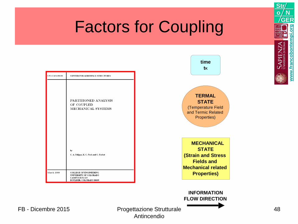
Factors for Coupling
MECHANICAL
STATE
(Strain and Stress
Fields and
Mechanical related
Properties)
TERMAL
STATE(Temperature Field
and Termic Related
Properties)
INFORMATION
FLOW DIRECTION
time
tK
ww
w.f
ran
co
bo
nte
mp
i.o
rg
Stro N
GER
FB - Dicembre 2015 Progettazione Strutturale
Antincendio
48
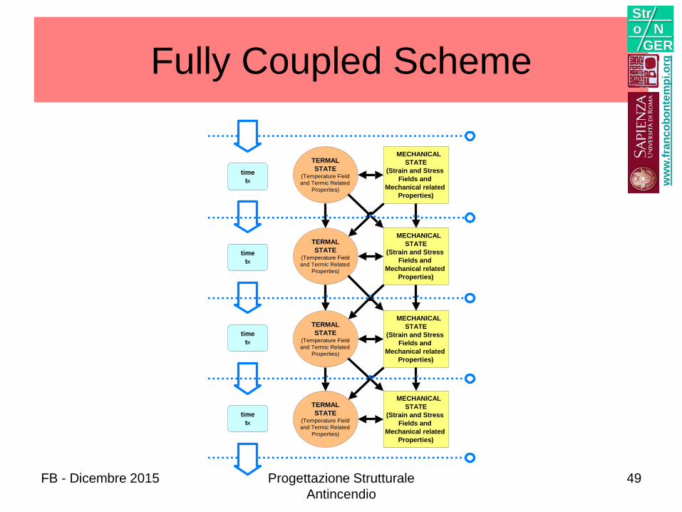
Fully Coupled Scheme
time
tK
TERMAL
STATE(Temperature Field
and Termic Related
Properties)
MECHANICAL
STATE
(Strain and Stress
Fields and
Mechanical related
Properties)
time
tK
TERMAL
STATE(Temperature Field
and Termic Related
Properties)
MECHANICAL
STATE
(Strain and Stress
Fields and
Mechanical related
Properties)
time
tK
TERMAL
STATE(Temperature Field
and Termic Related
Properties)
MECHANICAL
STATE
(Strain and Stress
Fields and
Mechanical related
Properties)
time
tK
TERMAL
STATE(Temperature Field
and Termic Related
Properties)
MECHANICAL
STATE
(Strain and Stress
Fields and
Mechanical related
Properties)
ww
w.f
ran
co
bo
nte
mp
i.o
rg
Stro N
GER
FB - Dicembre 2015 Progettazione Strutturale
Antincendio
49
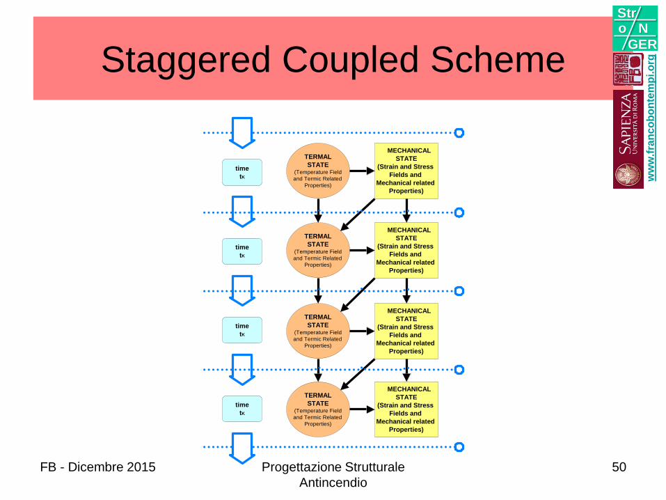
Staggered Coupled Scheme
time
tK
TERMAL
STATE(Temperature Field
and Termic Related
Properties)
MECHANICAL
STATE
(Strain and Stress
Fields and
Mechanical related
Properties)
time
tK
TERMAL
STATE(Temperature Field
and Termic Related
Properties)
MECHANICAL
STATE
(Strain and Stress
Fields and
Mechanical related
Properties)
time
tK
TERMAL
STATE(Temperature Field
and Termic Related
Properties)
MECHANICAL
STATE
(Strain and Stress
Fields and
Mechanical related
Properties)
time
tK
TERMAL
STATE(Temperature Field
and Termic Related
Properties)
MECHANICAL
STATE
(Strain and Stress
Fields and
Mechanical related
Properties)
ww
w.f
ran
co
bo
nte
mp
i.o
rg
Stro N
GER
FB - Dicembre 2015 Progettazione Strutturale
Antincendio
50

Temperature Driven Scheme
time
tK
TERMAL
STATE(Temperature Field
and Termic Related
Properties)
MECHANICAL
STATE
(Strain and Stress
Fields and
Mechanical related
Properties)
time
tK
TERMAL
STATE(Temperature Field
and Termic Related
Properties)
MECHANICAL
STATE
(Strain and Stress
Fields and
Mechanical related
Properties)
time
tK
TERMAL
STATE(Temperature Field
and Termic Related
Properties)
MECHANICAL
STATE
(Strain and Stress
Fields and
Mechanical related
Properties)
time
tK
TERMAL
STATE(Temperature Field
and Termic Related
Properties)
MECHANICAL
STATE
(Strain and Stress
Fields and
Mechanical related
Properties)
ww
w.f
ran
co
bo
nte
mp
i.o
rg
Stro N
GER
FB - Dicembre 2015 Progettazione Strutturale
Antincendio
51

Scheme With No Memory
time
tK
TERMAL
STATE(Temperature Field
and Termic Related
Properties)
MECHANICAL
STATE
(Strain and Stress
Fields and
Mechanical related
Properties)
time
tK
TERMAL
STATE(Temperature Field
and Termic Related
Properties)
MECHANICAL
STATE
(Strain and Stress
Fields and
Mechanical related
Properties)
time
tK
TERMAL
STATE(Temperature Field
and Termic Related
Properties)
MECHANICAL
STATE
(Strain and Stress
Fields and
Mechanical related
Properties)
time
tK
TERMAL
STATE(Temperature Field
and Termic Related
Properties)
MECHANICAL
STATE
(Strain and Stress
Fields and
Mechanical related
Properties)
ww
w.f
ran
co
bo
nte
mp
i.o
rg
Stro N
GER
FB - Dicembre 2015 Progettazione Strutturale
Antincendio
52
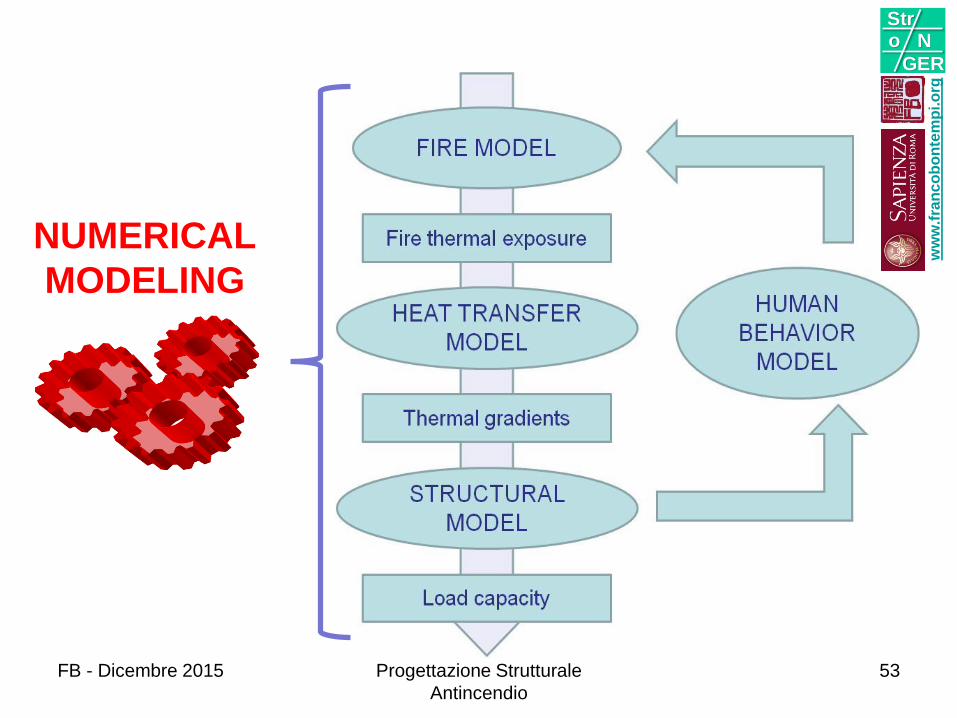
NUMERICAL
MODELING
ww
w.f
ran
co
bo
nte
mp
i.o
rg
Stro N
GER
FB - Dicembre 2015 Progettazione Strutturale
Antincendio
53
ww
w.f
ran
co
bo
nte
mp
i.o
rg
Stro N
GER
FB - Dicembre 2015 Progettazione Strutturale
Antincendio
54
ww
w.f
ran
co
bo
nte
mp
i.o
rg
Stro N
GER
FB - Dicembre 2015 Progettazione Strutturale
Antincendio
55
ww
w.f
ran
co
bo
nte
mp
i.o
rg
Stro N
GER
FB - Dicembre 2015 Progettazione Strutturale
Antincendio
56

ww
w.f
ran
co
bo
nte
mp
i.o
rg
Stro N
GER
FB - Dicembre 2015 Progettazione Strutturale
Antincendio
57
58
ww
w.f
ran
co
bo
nte
mp
i.o
rg
Stro N
GER
FB - Dicembre 2015 Progettazione Strutturale
Antincendio
58
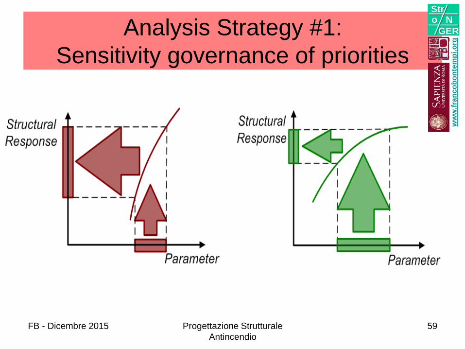
Analysis Strategy #1:
Sensitivity governance of priorities
ww
w.f
ran
co
bo
nte
mp
i.o
rg
Stro N
GER
FB - Dicembre 2015 Progettazione Strutturale
Antincendio
59
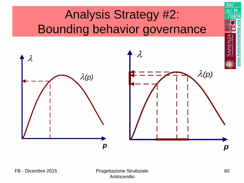
Analysis Strategy #2:
Bounding behavior governance
p
(p)
p
(p)
ww
w.f
ran
co
bo
nte
mp
i.o
rg
Stro N
GER
FB - Dicembre 2015 Progettazione Strutturale
Antincendio
60
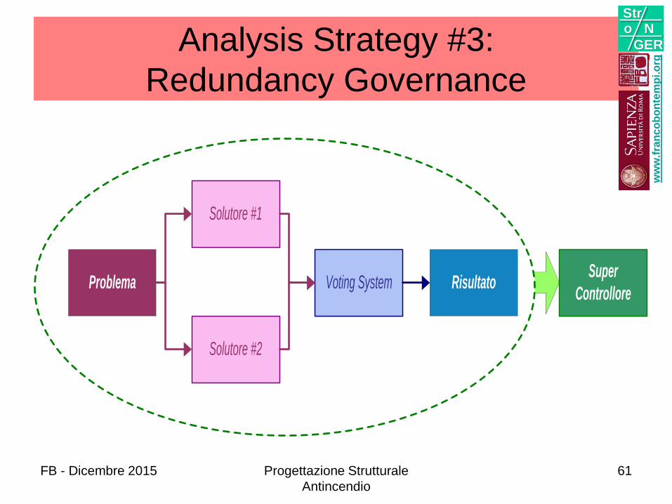
Super
ControlloreProblema Risultato
Solutore #1
Solutore #2
Voting System
Analysis Strategy #3:
Redundancy Governance
ww
w.f
ran
co
bo
nte
mp
i.o
rg
Stro N
GER
FB - Dicembre 2015 Progettazione Strutturale
Antincendio
61

SICUREZZA
ww
w.f
ran
co
bo
nte
mp
i.o
rg
Stro N
GER
FB - Dicembre 2015 Progettazione Strutturale
Antincendio
62
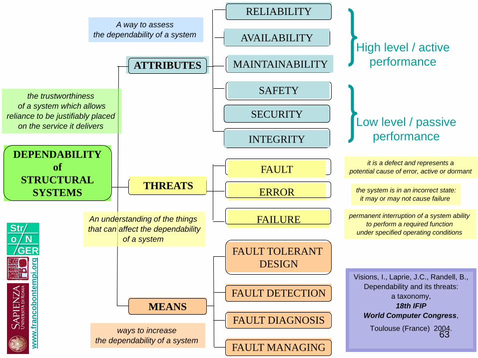
ATTRIBUTES
THREATS
MEANS
RELIABILITY
FAILURE
ERROR
FAULT
FAULT TOLERANT
DESIGN
FAULT DETECTION
FAULT DIAGNOSIS
FAULT MANAGING
DEPENDABILITY
of
STRUCTURAL
SYSTEMS
AVAILABILITY
SAFETY
MAINTAINABILITY
permanent interruption of a system ability
to perform a required function
under specified operating conditions
the system is in an incorrect state:
it may or may not cause failure
it is a defect and represents a
potential cause of error, active or dormant
INTEGRITY
ways to increase
the dependability of a system
An understanding of the things
that can affect the dependability
of a system
A way to assess
the dependability of a system
the trustworthiness
of a system which allows
reliance to be justifiably placed
on the service it delivers
SECURITY
High level / active
performance
Low level / passive
performance
Visions, I., Laprie, J.C., Randell, B.,
Dependability and its threats:
a taxonomy,
18th IFIP
World Computer Congress,
Toulouse (France) 2004.
ww
w.f
ran
co
bo
nte
mp
i.o
rg
Stro N
GER
63
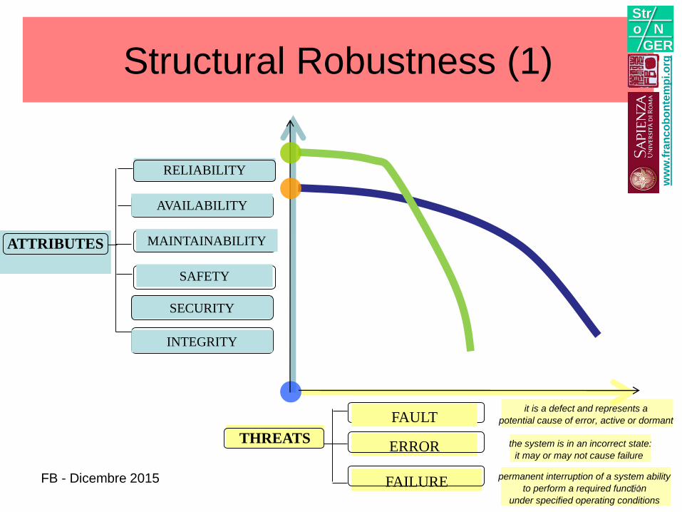
ATTRIBUTES
RELIABILITY
AVAILABILITY
SAFETY
MAINTAINABILITY
INTEGRITY
SECURITY
FAILURE
ERROR
FAULT
permanent interruption of a system ability
to perform a required function
under specified operating conditions
the system is in an incorrect state:
it may or may not cause failure
it is a defect and represents a
potential cause of error, active or dormant
THREATS
Structural Robustness (1)
64
ww
w.f
ran
co
bo
nte
mp
i.o
rg
Stro N
GER
FB - Dicembre 2015
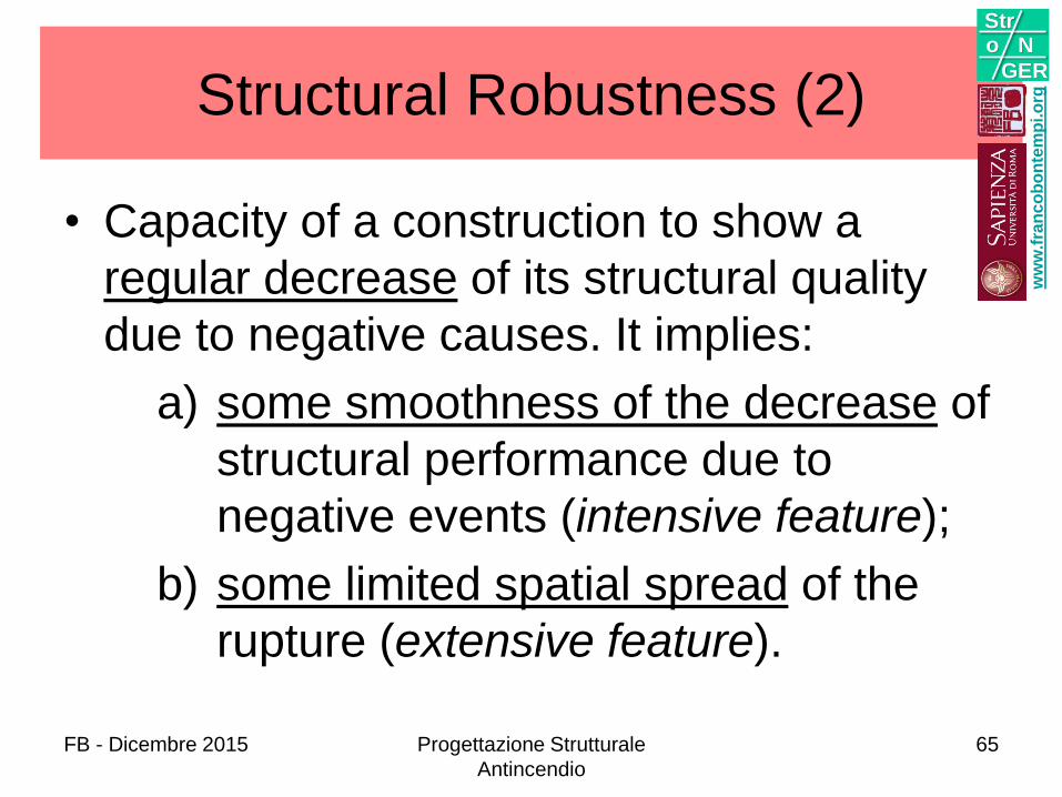
Structural Robustness (2)
• Capacity of a construction to show a
regular decrease of its structural quality
due to negative causes. It implies:
a) some smoothness of the decrease of
structural performance due to
negative events (intensive feature);
b) some limited spatial spread of the
rupture (extensive feature).
ww
w.f
ran
co
bo
nte
mp
i.o
rg
Stro N
GER
FB - Dicembre 2015 Progettazione Strutturale
Antincendio
65
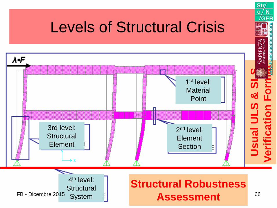
Levels of Structural Crisis
Usu
al
UL
S &
SL
S
Ve
rifi
ca
tio
n F
orm
at
Structural Robustness
Assessment
1st level:
Material
Point
2nd level:
Element
Section
3rd level:
Structural
Element
4th level:
Structural
System
ww
w.f
ran
co
bo
nte
mp
i.o
rg
Stro N
GER
FB - Dicembre 2015 66
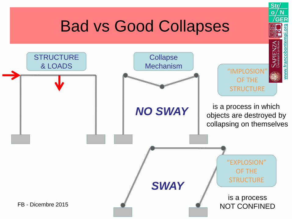
Bad vs Good Collapses
STRUCTURE
& LOADS
Collapse
Mechanism
NO SWAY
“IMPLOSION”OF THE
STRUCTURE
“EXPLOSION”OF THE
STRUCTURE
is a process in which
objects are destroyed by
collapsing on themselves
is a process
NOT CONFINED
SWAY
ww
w.f
ran
co
bo
nte
mp
i.o
rg
Stro N
GER
FB - Dicembre 2015
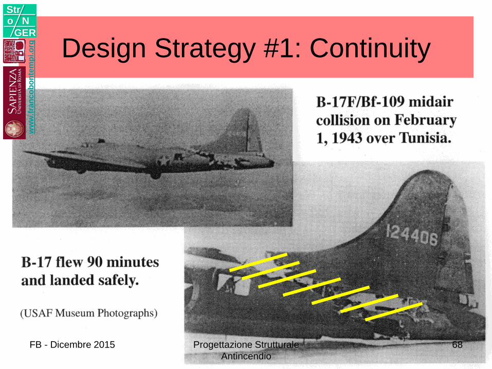
Design Strategy #1: Continuityw
ww
.fra
nc
ob
on
tem
pi.o
rg
Stro N
GER
FB - Dicembre 2015 Progettazione Strutturale
Antincendio
68
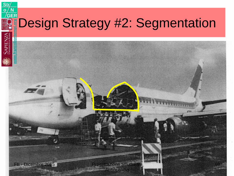
Design Strategy #2: Segmentationw
ww
.fra
nc
ob
on
tem
pi.o
rg
Stro N
GER
FB - Dicembre 2015 Progettazione Strutturale
Antincendio
69
AZIONENatura dell’azione incendio
Carattere accidentale
Carattere estensivo
Carattere intensivo
3w
ww
.fra
nc
ob
on
tem
pi.o
rg
Stro N
GER
FB - Dicembre 2015 Progettazione Strutturale
Antincendio
70
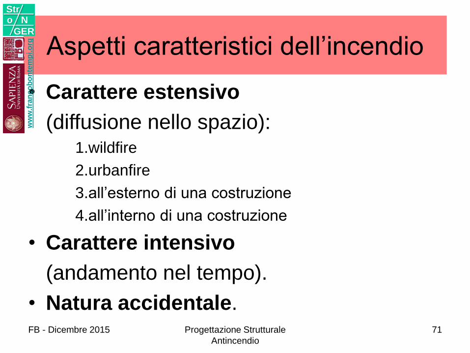
Aspetti caratteristici dell’incendio
• Carattere estensivo
(diffusione nello spazio):1.wildfire
2.urbanfire
3.all’esterno di una costruzione
4.all’interno di una costruzione
• Carattere intensivo
(andamento nel tempo).
• Natura accidentale.
ww
w.f
ran
co
bo
nte
mp
i.o
rg
Stro N
GER
FB - Dicembre 2015 Progettazione Strutturale
Antincendio
71
Carattere intensivo
ww
w.f
ran
co
bo
nte
mp
i.o
rg
Stro N
GER
FB - Dicembre 2015 Progettazione Strutturale
Antincendio
72
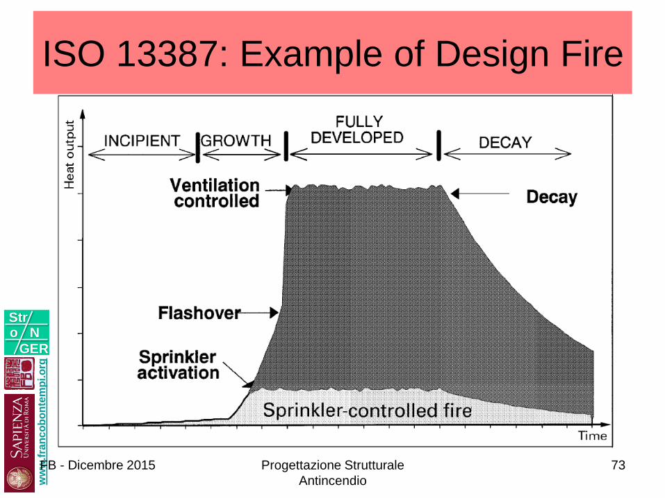
ISO 13387: Example of Design Firew
ww
.fra
nc
ob
on
tem
pi.o
rg
Stro N
GER
FB - Dicembre 2015 Progettazione Strutturale
Antincendio
73
ww
w.f
ran
co
bo
nte
mp
i.o
rg
Stro N
GER
74
fla
sho
ver
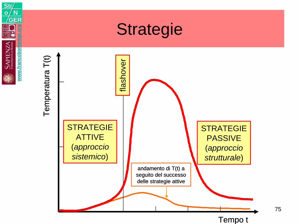
STRATEGIE
ATTIVE
(approccio
sistemico)
STRATEGIE
PASSIVE
(approccio
strutturale)
Tempo t
Tem
pera
tura
T(t
)
andamento di T(t) a
seguito del successo
delle strategie attive
fla
sho
ver
STRATEGIE
ATTIVE
(approccio
sistemico)
STRATEGIE
PASSIVE
(approccio
strutturale)
Tempo t
Tem
pera
tura
T(t
)
andamento di T(t) a
seguito del successo
delle strategie attive
Strategiew
ww
.fra
nc
ob
on
tem
pi.o
rg
Stro N
GER
75
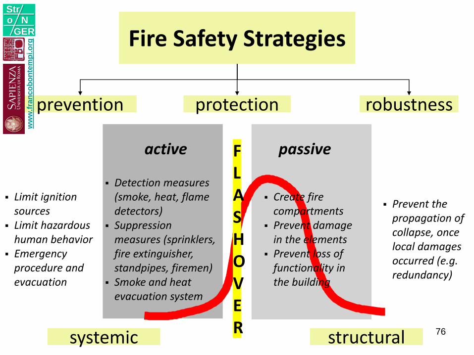
FLASHOVER
passive
Create fire compartments
Prevent damage in the elements
Prevent loss of functionality in the building
active
Detection measures(smoke, heat, flame detectors)
Suppression measures (sprinklers, fire extinguisher, standpipes, firemen)
Smoke and heat evacuation system
prevention protection robustness
Limit ignitionsources
Limit hazardous human behavior
Emergency procedure and evacuation
Prevent the propagation of collapse, once local damages occurred (e.g. redundancy)
Fire Safety Strategies
systemic structural
ww
w.f
ran
co
bo
nte
mp
i.o
rg
Stro N
GER
76
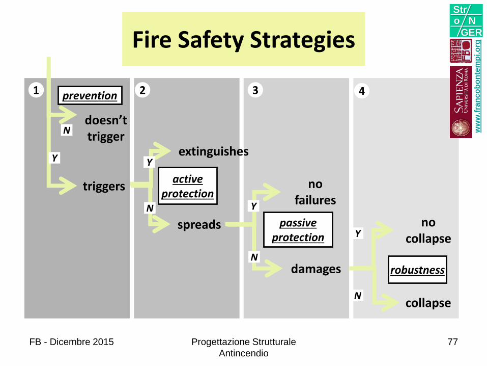
activeprotection
passiveprotection
no failures
doesn’t trigger
Y
N
Y
N
spreads
extinguishes
damages
Y
Nrobustness
no collapse
collapse
Y
N
triggers
prevention1 42 3
Fire Safety Strategies
ww
w.f
ran
co
bo
nte
mp
i.o
rg
Stro N
GER
FB - Dicembre 2015 Progettazione Strutturale
Antincendio
77

ww
w.f
ran
co
bo
nte
mp
i.o
rg
Stro N
GER
FB - Dicembre 2015 Progettazione Strutturale
Antincendio
78
ww
w.f
ran
co
bo
nte
mp
i.o
rg
Stro N
GER
FB - Dicembre 2015 Progettazione Strutturale
Antincendio
79
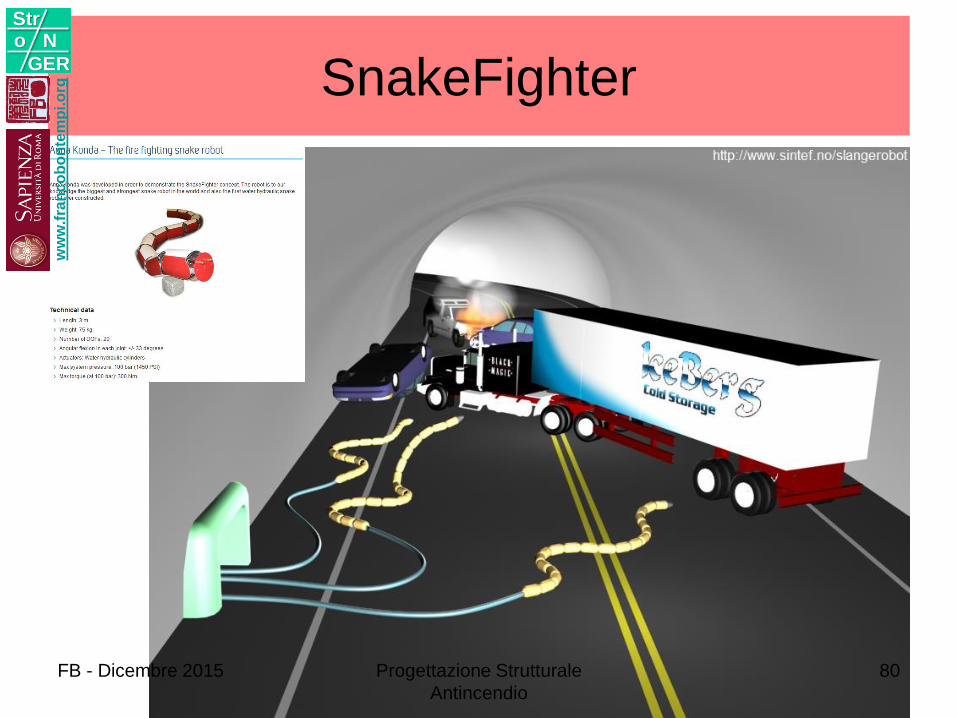
SnakeFighter w
ww
.fra
nc
ob
on
tem
pi.o
rg
Stro N
GER
FB - Dicembre 2015 Progettazione Strutturale
Antincendio
80
SVILUPPODinamica degli incendi in galleria
Effetti della ventilazione
4w
ww
.fra
nc
ob
on
tem
pi.o
rg
Stro N
GER
FB - Dicembre 2015 Progettazione Strutturale
Antincendio
81
FIRE DYNAMICS IN TUNNELS
ww
w.f
ran
co
bo
nte
mp
i.o
rg
Stro N
GER
FB - Dicembre 2015 Progettazione Strutturale
Antincendio
82
FB - Dicembre 2015 Progettazione Strutturale
Antincendio
83
ww
w.f
ran
co
bo
nte
mp
i.o
rg
Stro N
GER
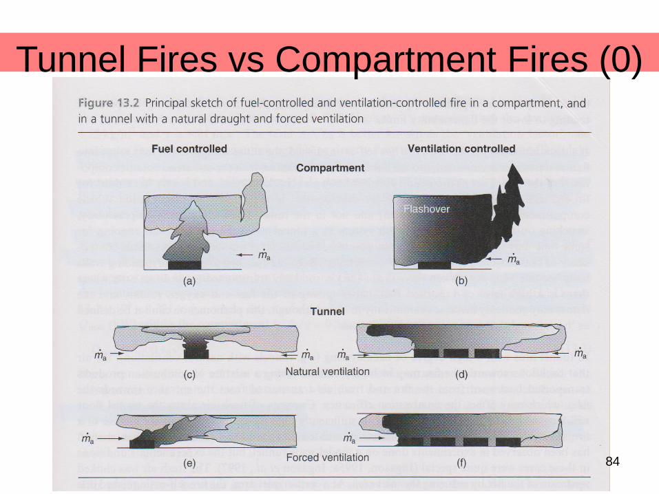
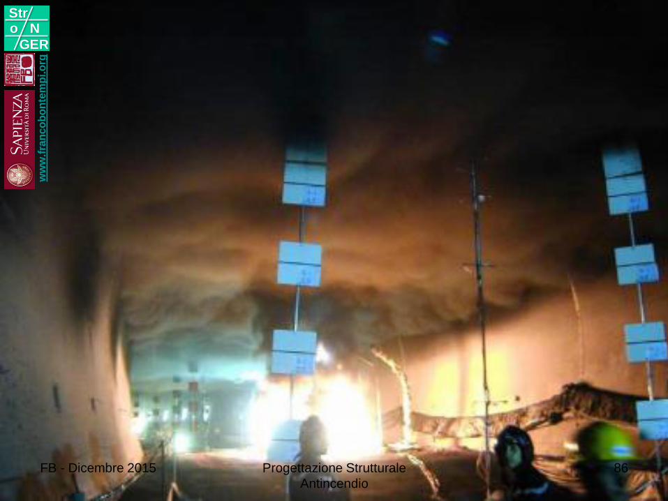
Tunnel Fires vs Compartment Fires (0)
84
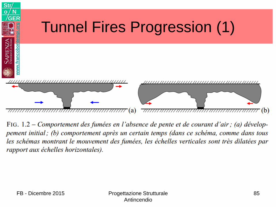
Tunnel Fires Progression (1)w
ww
.fra
nc
ob
on
tem
pi.o
rg
Stro N
GER
FB - Dicembre 2015 Progettazione Strutturale
Antincendio
85
ww
w.f
ran
co
bo
nte
mp
i.o
rg
Stro N
GER
FB - Dicembre 2015 Progettazione Strutturale
Antincendio
86
ww
w.f
ran
co
bo
nte
mp
i.o
rg
Stro N
GER
FB - Dicembre 2015 87
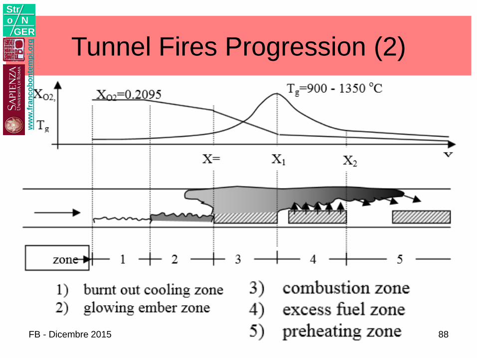
Tunnel Fires Progression (2)w
ww
.fra
nc
ob
on
tem
pi.o
rg
Stro N
GER
FB - Dicembre 2015 88
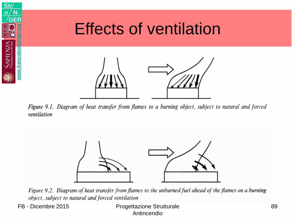
Effects of ventilationw
ww
.fra
nc
ob
on
tem
pi.o
rg
Stro N
GER
FB - Dicembre 2015 Progettazione Strutturale
Antincendio
89

Temperature developmentw
ww
.fra
nc
ob
on
tem
pi.o
rg
Stro N
GER
Smoke development
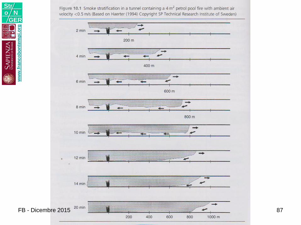
• A smoke layer may be created in tunnels at the early stages of a fire with essentially no longitudinal ventilation. However, the smoke layer will gradually descend further from the fire.
• If the tunnel is very long, the smoke layer may descend to the tunnel surface at a specific distance from the fire depending on the fire size, tunnel type, and the perimeter and height of the tunnel cross section.
• When the longitudinal ventilation is gradually increased, the stratified layer will gradually dissolve.
• A backlayering of smoke is created on the upstream side of the fire.
• Downstream from the fire there is a degree of stratification of the smoke that is governed by the heat losses to the surrounding walls and by the turbulent mixing between the buoyant smoke layers and the normally opposite moving cold layer.
ww
w.f
ran
co
bo
nte
mp
i.o
rg
Stro N
GER
FB - Dicembre 2015 Progettazione Strutturale
Antincendio
91
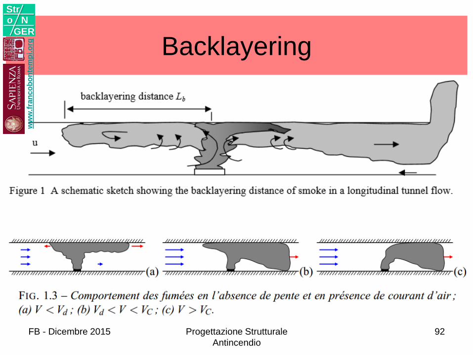
Backlayeringw
ww
.fra
nc
ob
on
tem
pi.o
rg
Stro N
GER
FB - Dicembre 2015 Progettazione Strutturale
Antincendio
92
ww
w.f
ran
co
bo
nte
mp
i.o
rg
Stro N
GER
FB - Dicembre 2015 93
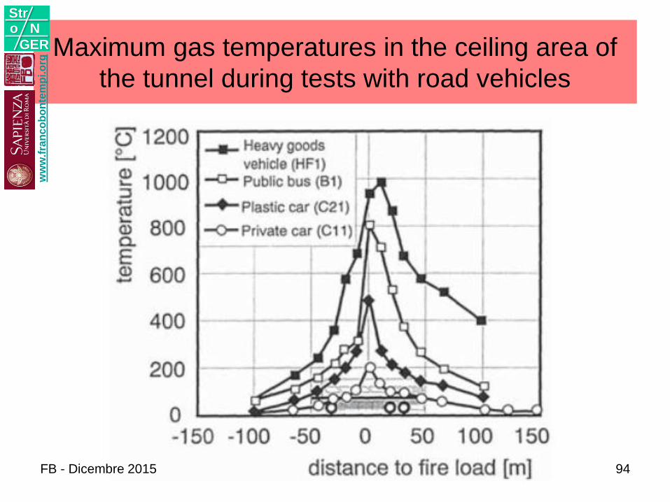
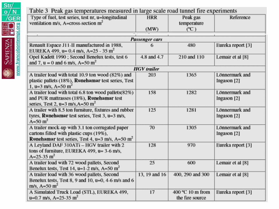
Maximum gas temperatures in the ceiling area of
the tunnel during tests with road vehicles
ww
w.f
ran
co
bo
nte
mp
i.o
rg
Stro N
GER
FB - Dicembre 2015 94
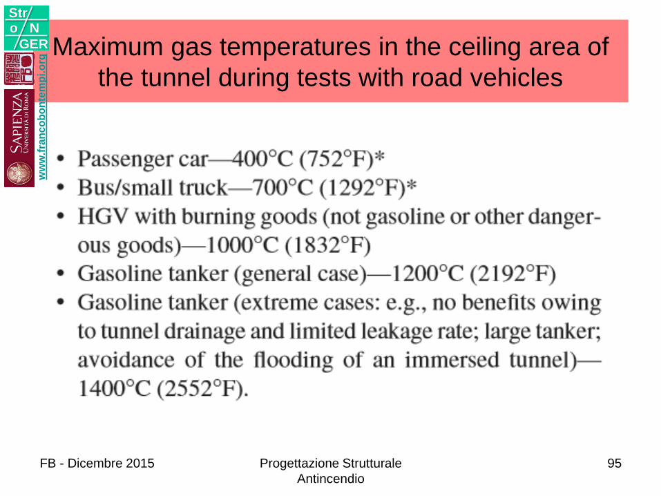
Maximum gas temperatures in the ceiling area of
the tunnel during tests with road vehicles
ww
w.f
ran
co
bo
nte
mp
i.o
rg
Stro N
GER
FB - Dicembre 2015 Progettazione Strutturale
Antincendio
95
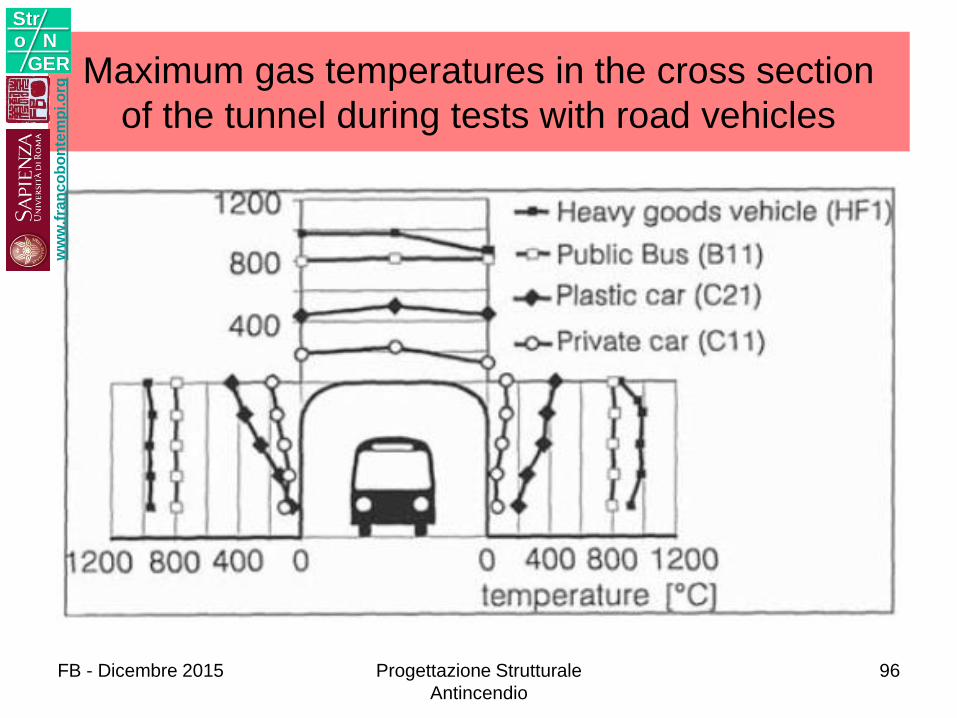
Maximum gas temperatures in the cross section
of the tunnel during tests with road vehicles
ww
w.f
ran
co
bo
nte
mp
i.o
rg
Stro N
GER
FB - Dicembre 2015 Progettazione Strutturale
Antincendio
96
EMERGENCY VENTILATION
ww
w.f
ran
co
bo
nte
mp
i.o
rg
Stro N
GER
FB - Dicembre 2015 Progettazione Strutturale
Antincendio
97
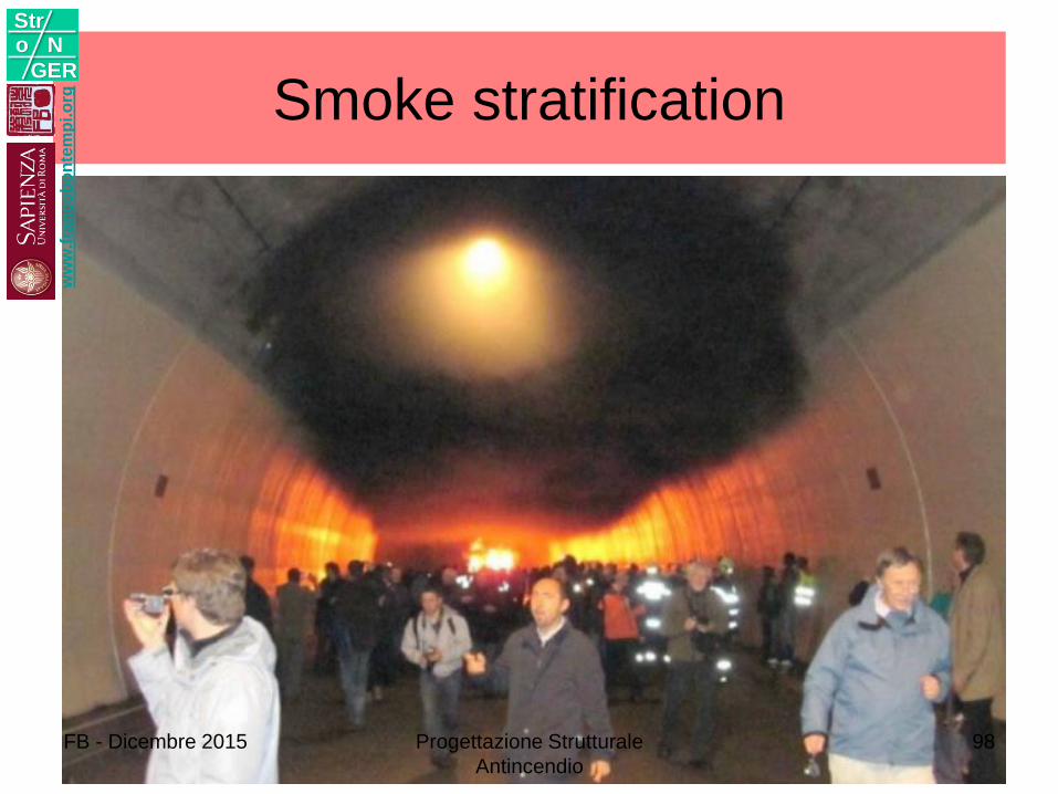
Smoke stratification w
ww
.fra
nc
ob
on
tem
pi.o
rg
Stro N
GER
FB - Dicembre 2015 Progettazione Strutturale
Antincendio
98
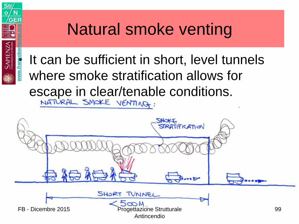
• It can be sufficient in short, level tunnels
where smoke stratification allows for
escape in clear/tenable conditions.
Natural smoke ventingw
ww
.fra
nc
ob
on
tem
pi.o
rg
Stro N
GER
FB - Dicembre 2015 Progettazione Strutturale
Antincendio
99
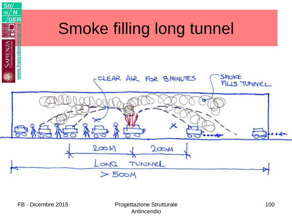
Smoke filling long tunnel w
ww
.fra
nc
ob
on
tem
pi.o
rg
Stro N
GER
FB - Dicembre 2015 Progettazione Strutturale
Antincendio
100
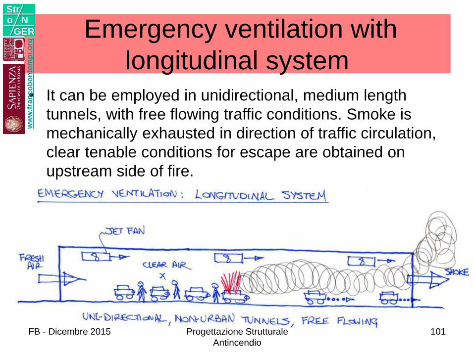
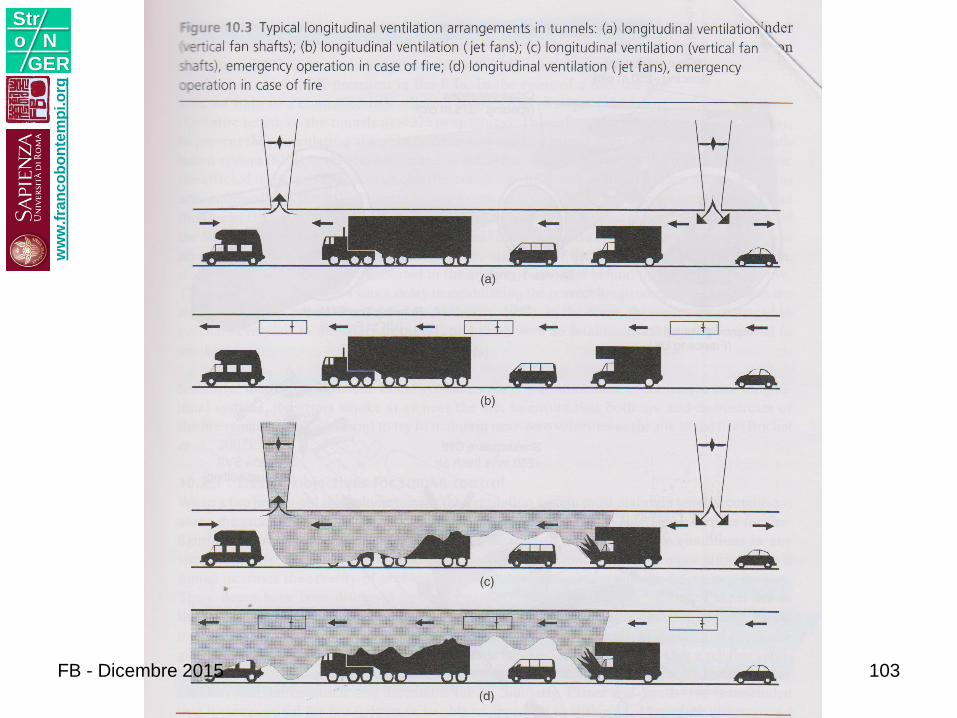
Emergency ventilation with
longitudinal system
• It can be employed in unidirectional, medium length
tunnels, with free flowing traffic conditions. Smoke is
mechanically exhausted in direction of traffic circulation,
clear tenable conditions for escape are obtained on
upstream side of fire.
ww
w.f
ran
co
bo
nte
mp
i.o
rg
Stro N
GER
FB - Dicembre 2015 Progettazione Strutturale
Antincendio
101
ww
w.f
ran
co
bo
nte
mp
i.o
rg
Stro N
GER
FB - Dicembre 2015 Progettazione Strutturale
Antincendio
102
ww
w.f
ran
co
bo
nte
mp
i.o
rg
Stro N
GER
FB - Dicembre 2015 103
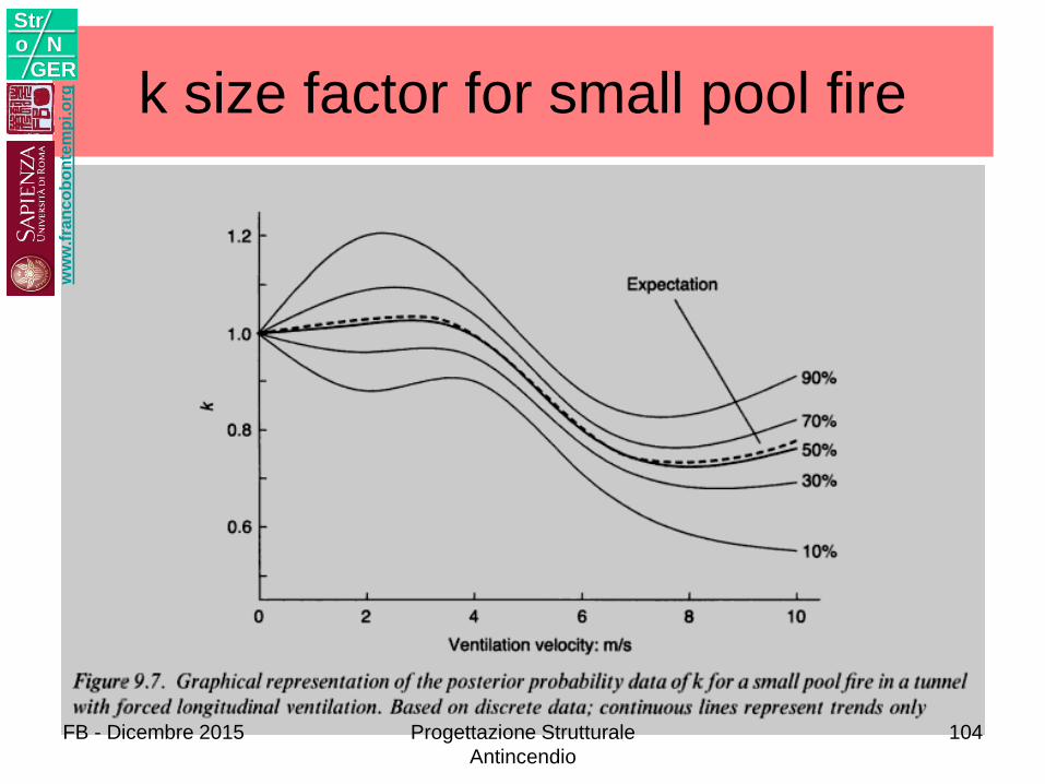
k size factor for small pool firew
ww
.fra
nc
ob
on
tem
pi.o
rg
Stro N
GER
FB - Dicembre 2015 Progettazione Strutturale
Antincendio
104
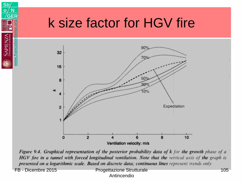
k size factor for HGV firew
ww
.fra
nc
ob
on
tem
pi.o
rg
Stro N
GER
FB - Dicembre 2015 Progettazione Strutturale
Antincendio
105
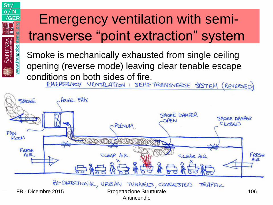
Emergency ventilation with semi-
transverse “point extraction” system
• Smoke is mechanically exhausted from single ceiling
opening (reverse mode) leaving clear tenable escape
conditions on both sides of fire.
ww
w.f
ran
co
bo
nte
mp
i.o
rg
Stro N
GER
FB - Dicembre 2015 Progettazione Strutturale
Antincendio
106
ww
w.f
ran
co
bo
nte
mp
i.o
rg
Stro N
GER
FB - Dicembre 2015 107
Observation: goal
• The purpose of controlling the spread of smoke is to keep people as long as possible in a smoke-free environment.
• This means that the smoke stratification must be kept intact, leaving a more or less clear and breathable air underneath the smoke layer.
• The stratified smoke is taken out of the tunnel through exhaust openings located in the ceiling or at the top of the sidewalls.
ww
w.f
ran
co
bo
nte
mp
i.o
rg
Stro N
GER
FB - Dicembre 2015 Progettazione Strutturale
Antincendio
108
Observation: longitudinal velocity
• With practically zero longitudinal air velocity, the smoke layer expands to both sides of the fire. The smoke spreads in a stratified way for up to 10 min.
• After this initial phase, smoke begins to mix over the entire cross section, unless by this time the extraction is in full operation.
• The longitudinal velocity of the tunnel air must be below 2 m/s in the vicinity of the fire incidence zone. With higher velocities, the vertical turbulence in the shear layer between smoke and fresh air quickly cools the upper layer and the smoke then mixes over the entire cross section.
ww
w.f
ran
co
bo
nte
mp
i.o
rg
Stro N
GER
Progettazione Strutturale
Antincendio
109
Observations: turbulence
• With an air velocity of around 2 m/s, most of the
smoke of a medium-size fire spreads to one side
of the fire (limited backlayering) and starts
mixing over the whole cross section at a
distance of 400 to 600 m downstream of the fire
site. This mixing over the cross section can also
be prevented if the smoke extraction is activated
early enough.
• Vehicles standing in the longitudinal air flow
increase strongly the vertical turbulence and
encourage the vertical mixing of the smoke.
ww
w.f
ran
co
bo
nte
mp
i.o
rg
Stro N
GER
110
Observation: fresh air
• In a transverse ventilation system, the fresh air jets entering the tunnel at the floor level induce a rotation of the longitudinal airflow, which tends to bring the smoke layer down to the road.
• No fresh air is to be injected from the ceiling in a zone with smoke because this increases the amount of smoke and tends to suppress the stratification.
ww
w.f
ran
co
bo
nte
mp
i.o
rg
Stro N
GER
FB - Dicembre 2015 Progettazione Strutturale
Antincendio
111
Observation: smoke extraction
• In reversible semi-transverse ventilation with the
duct at the ceiling, the fresh air is added through
ceiling openings in normal ventilation operation.
• If a fire occurs, as long as fresh air is supplied
through ceiling openings, the smoke quantity
increases by this amount and strong jets tend to
bring the smoke down to the road surface. The
conversion of the duct from supply to extraction
must be done as quickly as possible.
ww
w.f
ran
co
bo
nte
mp
i.o
rg
Stro N
GER
FB - Dicembre 2015 Progettazione Strutturale
Antincendio
112
Observation: traffic conditions
• For a tunnel with one-way traffic, designed for queues (an urban area), the ventilation design must take into consideration that cars can likely stand to both sides of the fire because of the traffic. In urban areas it is usual to find stop-and-go traffic situations.
• For a tunnel with two-way traffic, where the vehicles run in both directions, it must be taken into consideration that in the event of a fire vehicles will generally be trapped on both sides of the fire.
ww
w.f
ran
co
bo
nte
mp
i.o
rg
Stro N
GER
FB - Dicembre 2015 Progettazione Strutturale
Antincendio
113
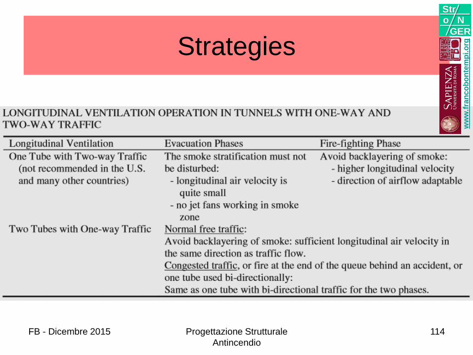
Strategies
ww
w.f
ran
co
bo
nte
mp
i.o
rg
Stro N
GER
FB - Dicembre 2015 Progettazione Strutturale
Antincendio
114
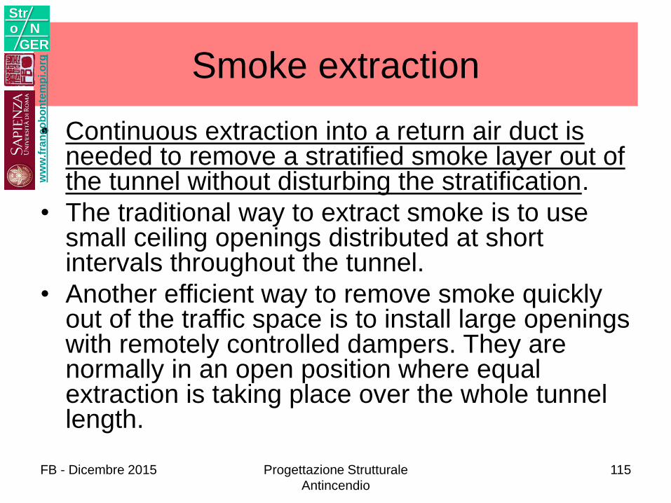
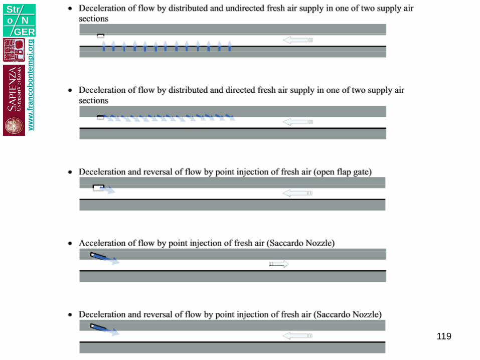
Smoke extraction
• Continuous extraction into a return air duct is needed to remove a stratified smoke layer out of the tunnel without disturbing the stratification.
• The traditional way to extract smoke is to use small ceiling openings distributed at short intervals throughout the tunnel.
• Another efficient way to remove smoke quickly out of the traffic space is to install large openings with remotely controlled dampers. They are normally in an open position where equal extraction is taking place over the whole tunnel length.
ww
w.f
ran
co
bo
nte
mp
i.o
rg
Stro N
GER
FB - Dicembre 2015 Progettazione Strutturale
Antincendio
115
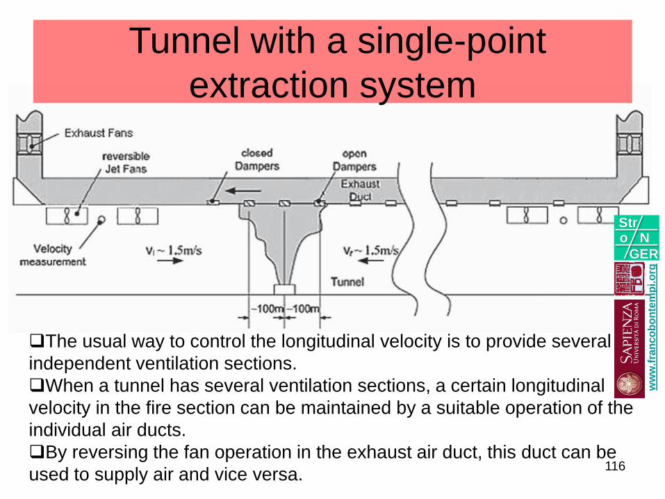
Tunnel with a single-point
extraction system
The usual way to control the longitudinal velocity is to provide several
independent ventilation sections.
When a tunnel has several ventilation sections, a certain longitudinal
velocity in the fire section can be maintained by a suitable operation of the
individual air ducts.
By reversing the fan operation in the exhaust air duct, this duct can be
used to supply air and vice versa.
ww
w.f
ran
co
bo
nte
mp
i.o
rg
Stro N
GER
116
FB - Dicembre 2015 Progettazione Strutturale
Antincendio
117
ww
w.f
ran
co
bo
nte
mp
i.o
rg
Stro N
GER
FIRE MODELING
ww
w.f
ran
co
bo
nte
mp
i.o
rg
Stro N
GER
FB - Dicembre 2015 Progettazione Strutturale
Antincendio
118
ww
w.f
ran
co
bo
nte
mp
i.o
rg
Stro N
GER
119
ww
w.f
ran
co
bo
nte
mp
i.o
rg
Stro N
GER
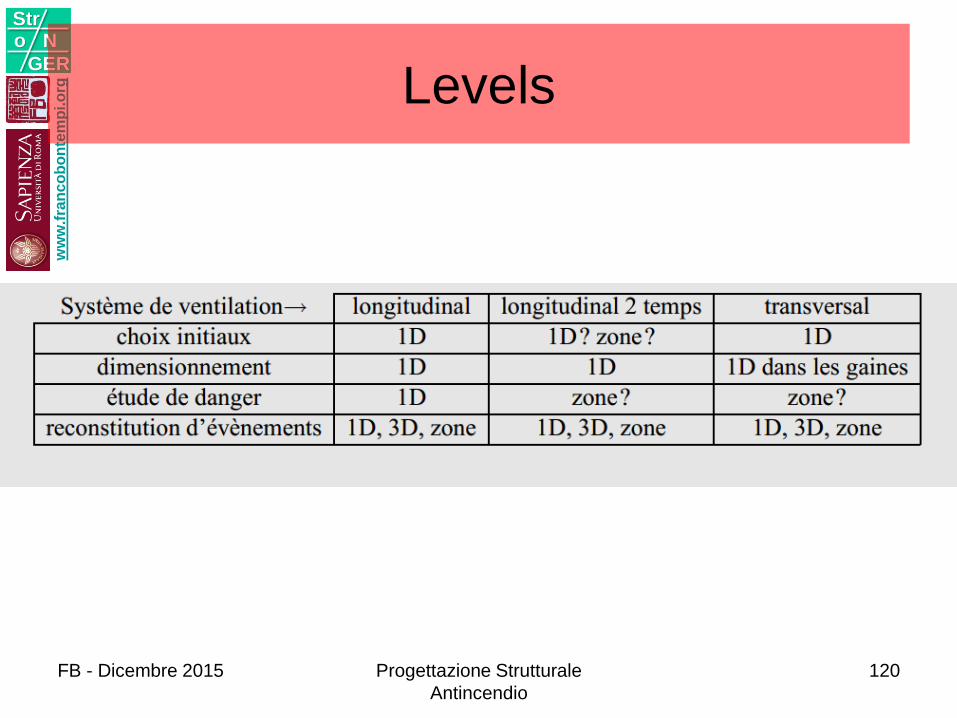
Levels
FB - Dicembre 2015 Progettazione Strutturale
Antincendio
120
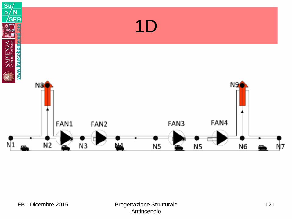
1Dw
ww
.fra
nc
ob
on
tem
pi.o
rg
Stro N
GER
FB - Dicembre 2015 Progettazione Strutturale
Antincendio
121
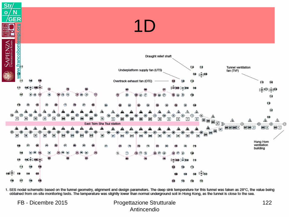
1Dw
ww
.fra
nc
ob
on
tem
pi.o
rg
Stro N
GER
FB - Dicembre 2015 Progettazione Strutturale
Antincendio
122
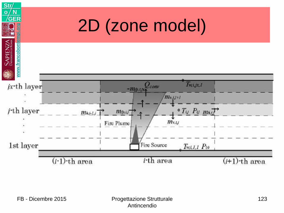
2D (zone model)w
ww
.fra
nc
ob
on
tem
pi.o
rg
Stro N
GER
FB - Dicembre 2015 Progettazione Strutturale
Antincendio
123
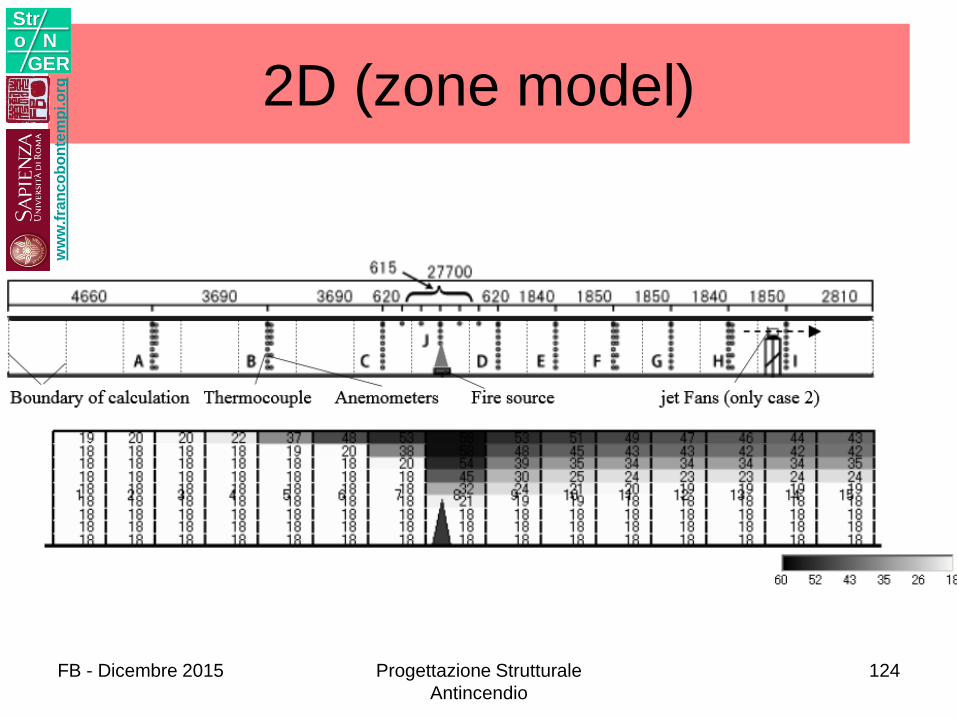
2D (zone model)w
ww
.fra
nc
ob
on
tem
pi.o
rg
Stro N
GER
FB - Dicembre 2015 Progettazione Strutturale
Antincendio
124
ww
w.f
ran
co
bo
nte
mp
i.o
rg
Stro N
GER
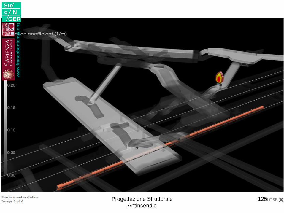
Progettazione Strutturale
Antincendio
125
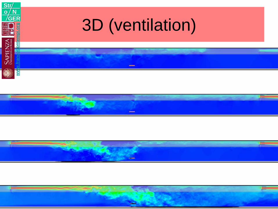
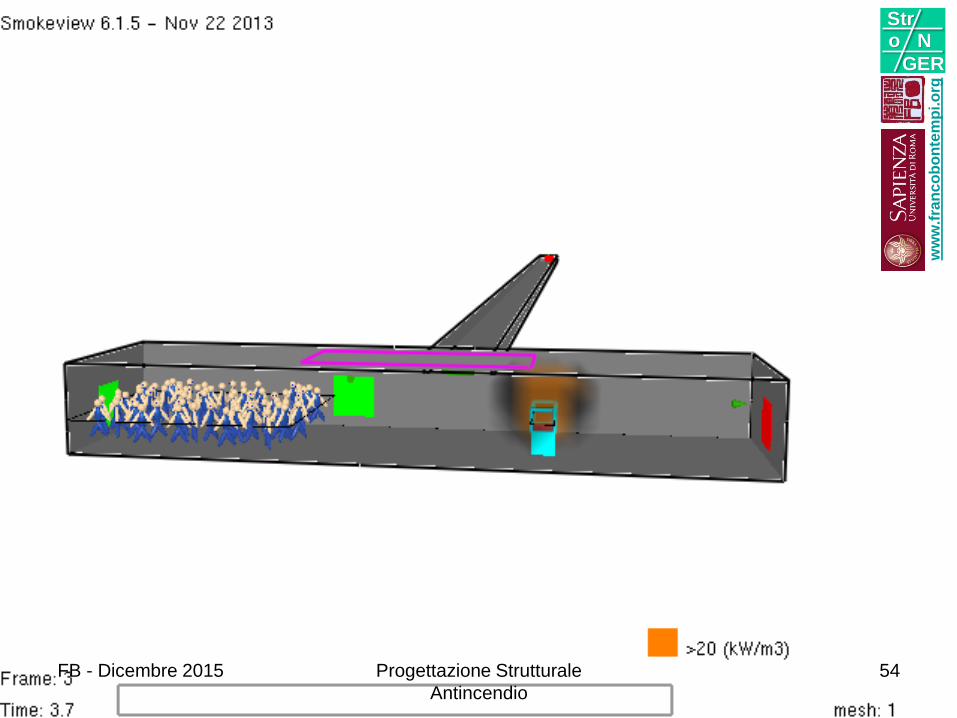
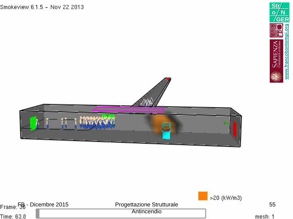
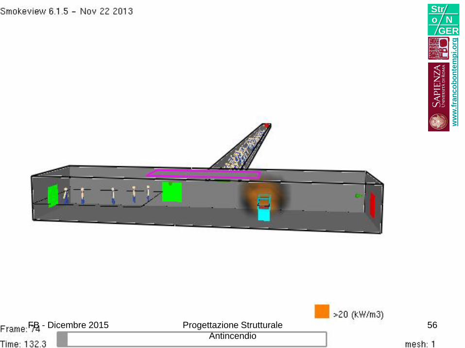
FDS Simulation3D (ventilation)
ww
w.f
ran
co
bo
nte
mp
i.o
rg
Stro N
GER
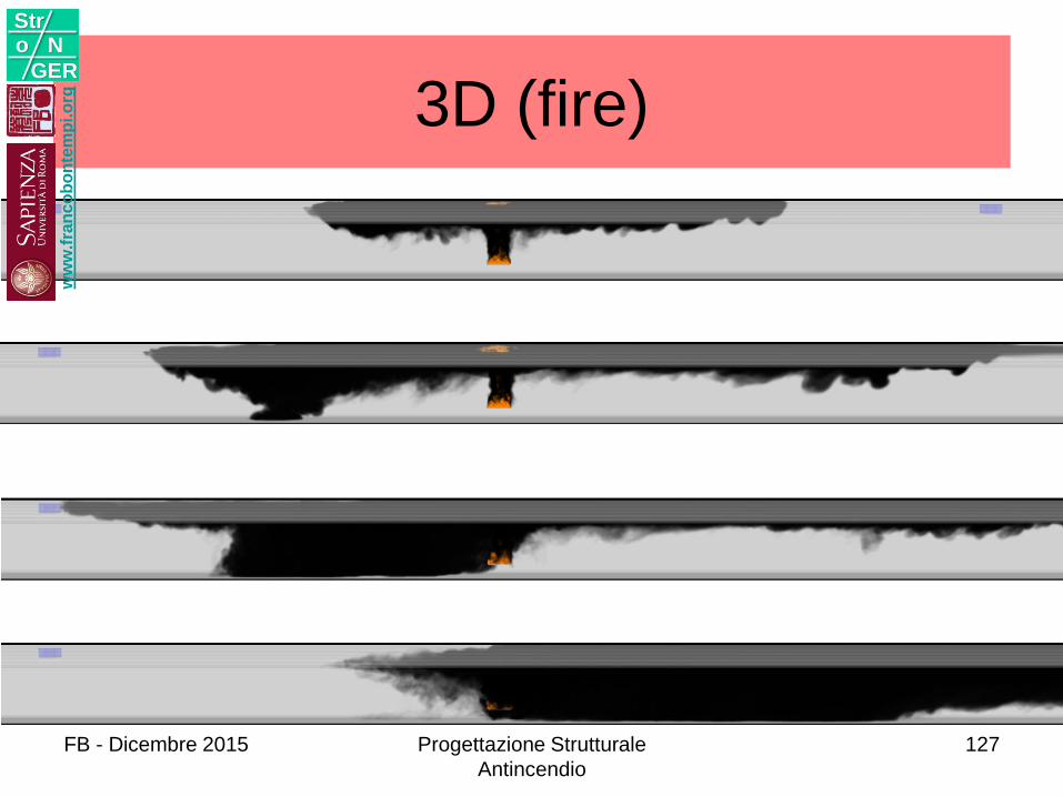
FDS Simulation3D (fire)
ww
w.f
ran
co
bo
nte
mp
i.o
rg
Stro N
GER
FB - Dicembre 2015 Progettazione Strutturale
Antincendio
127
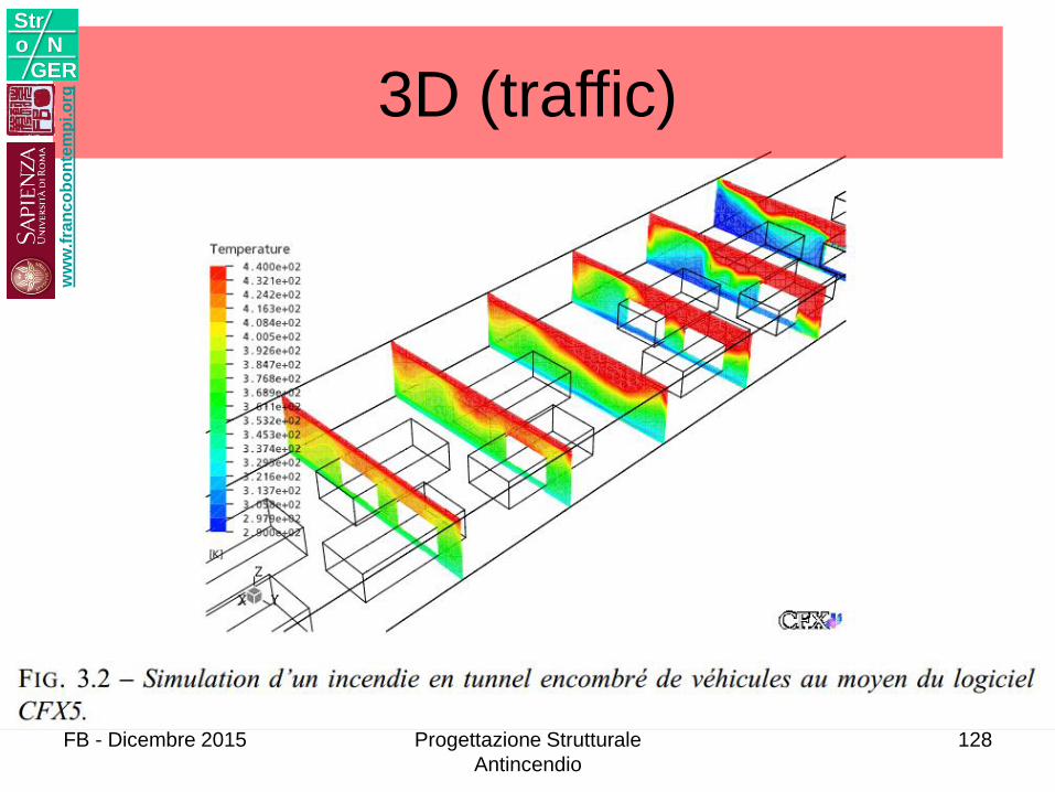
3D (traffic)w
ww
.fra
nc
ob
on
tem
pi.o
rg
Stro N
GER
FB - Dicembre 2015 Progettazione Strutturale
Antincendio
128
ww
w.f
ran
co
bo
nte
mp
i.o
rg
Stro N
GER
129
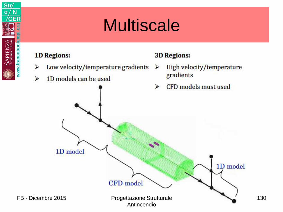
Multiscalew
ww
.fra
nc
ob
on
tem
pi.o
rg
Stro N
GER
FB - Dicembre 2015 Progettazione Strutturale
Antincendio
130
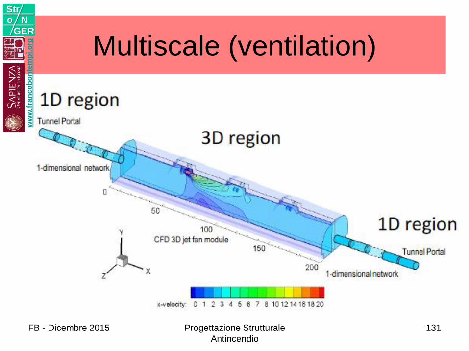
Multiscale (ventilation)w
ww
.fra
nc
ob
on
tem
pi.o
rg
Stro N
GER
FB - Dicembre 2015 Progettazione Strutturale
Antincendio
131

Multiscale (fire)w
ww
.fra
nc
ob
on
tem
pi.o
rg
Stro N
GER
FB - Dicembre 2015 Progettazione Strutturale
Antincendio
132
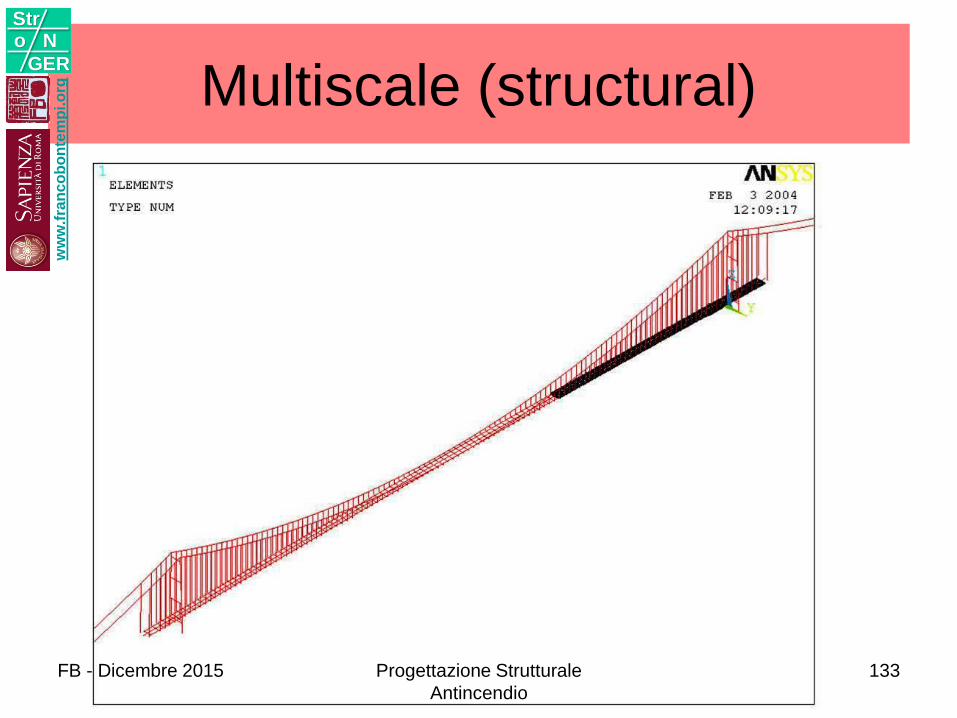
Multiscale (structural)w
ww
.fra
nc
ob
on
tem
pi.o
rg
Stro N
GER
FB - Dicembre 2015 Progettazione Strutturale
Antincendio
133
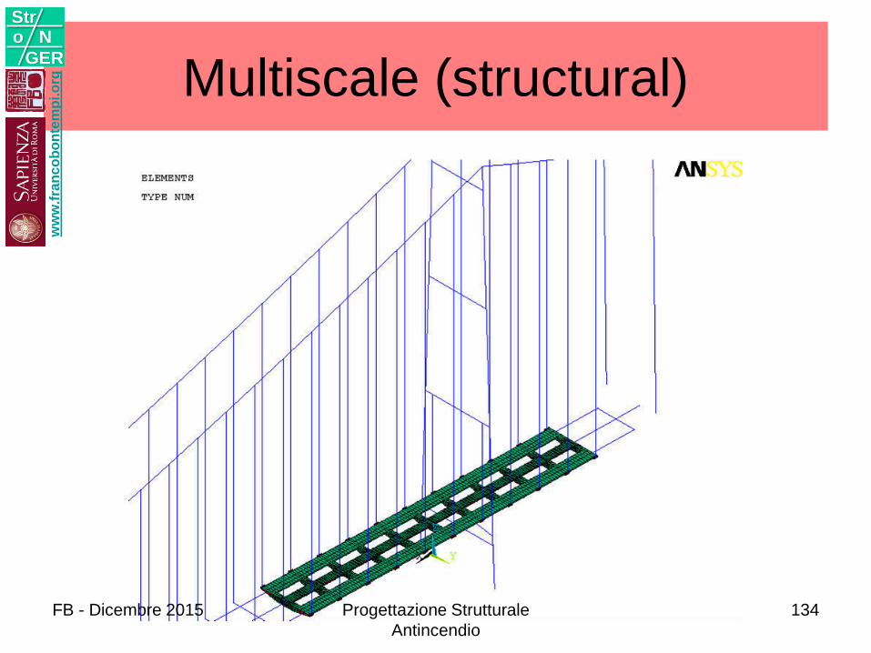
Multiscale (structural)w
ww
.fra
nc
ob
on
tem
pi.o
rg
Stro N
GER
FB - Dicembre 2015 Progettazione Strutturale
Antincendio
134
PROGETTOBasis
Failure path
Risk
5w
ww
.fra
nc
ob
on
tem
pi.o
rg
Stro N
GER
FB - Dicembre 2015 Progettazione Strutturale
Antincendio
135
BASIS
ww
w.f
ran
co
bo
nte
mp
i.o
rg
Stro N
GER
FB - Dicembre 2015 Progettazione Strutturale
Antincendio
136
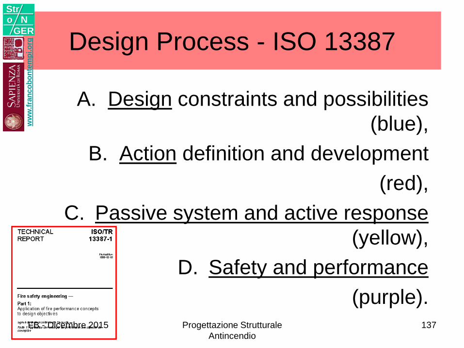
Design Process - ISO 13387
A. Design constraints and possibilities
(blue),
B. Action definition and development
(red),
C. Passive system and active response
(yellow),
D. Safety and performance
(purple).
3/22/2011
ww
w.f
ran
co
bo
nte
mp
i.o
rg
Stro N
GER
FB - Dicembre 2015 Progettazione Strutturale
Antincendio
137
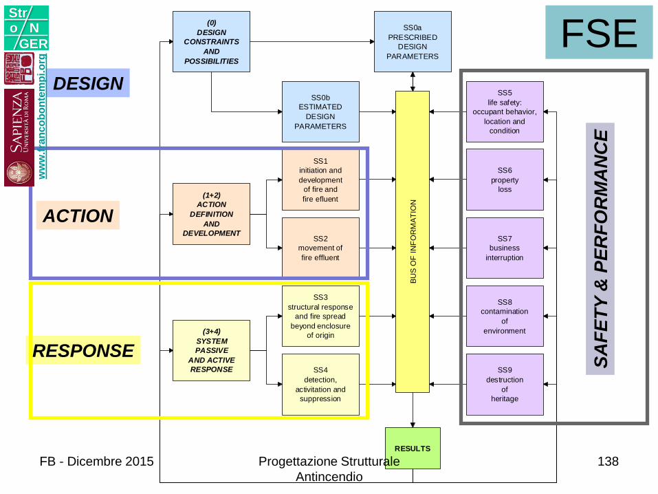
SS0a
PRESCRIBED
DESIGN
PARAMETERS
SS0b
ESTIMATED
DESIGN
PARAMETERS
SS1
initiation and
development
of fire and
fire efluent
SS2
movement of
fire effluent
SS3
structural response
and fire spread
beyond enclosure
of origin
SS4
detection,
activitation and
suppression
SS5
life safety:
occupant behavior,
location and
condition
SS6
property
loss
SS7
business
interruption
SS8
contamination
of
environment
SS9
destruction
of
heritage
(0)
DESIGN
CONSTRAINTS
AND
POSSIBILITIES
(1+2)
ACTION
DEFINITION
AND
DEVELOPMENT
(3+4)
SYSTEM
PASSIVE
AND ACTIVE
RESPONSE
BU
S O
F I
NF
OR
MA
TIO
N
RESULTS
DESIGN
ACTION
RESPONSE
SA
FE
TY
& P
ER
FO
RM
AN
CE
FSEw
ww
.fra
nc
ob
on
tem
pi.o
rg
Stro N
GER
FB - Dicembre 2015 Progettazione Strutturale
Antincendio
138
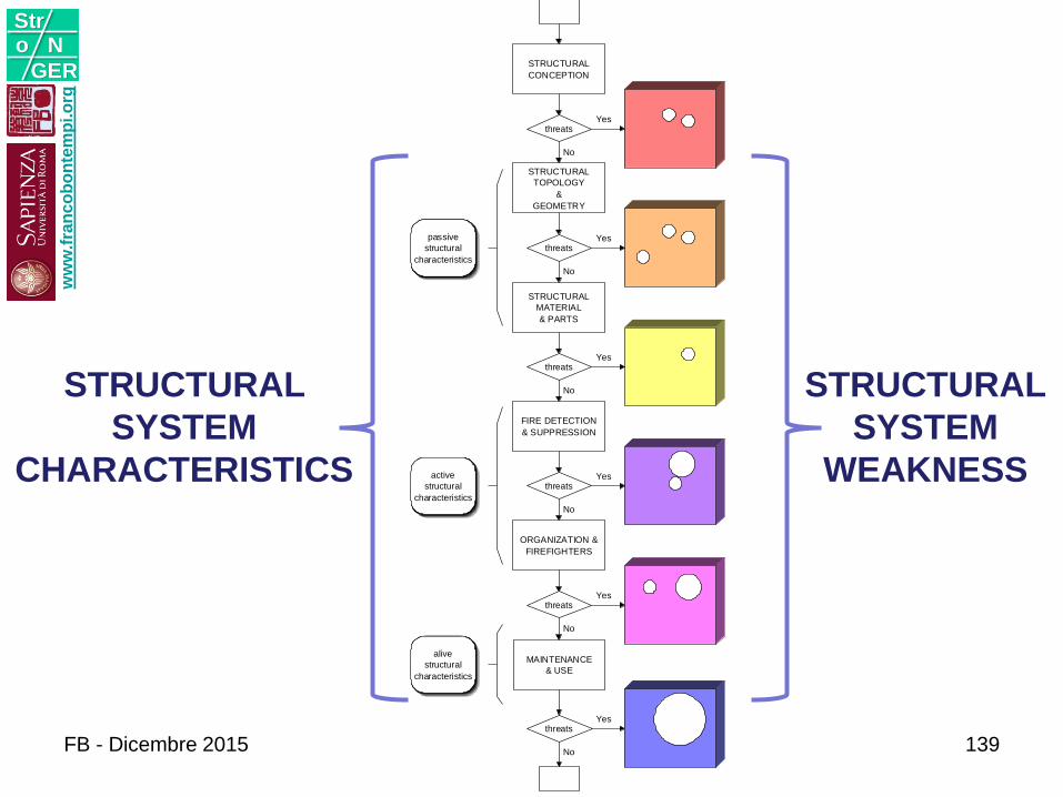
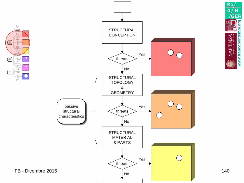
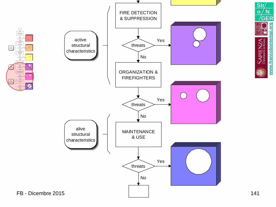
STRUCTURAL
CONCEPTION
STRUCTURAL
TOPOLOGY
&
GEOMETRY
threats
No
Yes
threats
STRUCTURAL
MATERIAL
& PARTS
No
Yespassive
structural
characteristics
threats
FIRE DETECTION
& SUPPRESSION
No
Yes
active
structural
characteristics
threats
ORGANIZATION &
FIREFIGHTERS
No
Yes
threats
MAINTENANCE
& USE
No
Yes
threats
No
alive
structural
characteristics
Yes
STRUCTURAL
SYSTEM
CHARACTERISTICS
STRUCTURAL
SYSTEM
WEAKNESS
ww
w.f
ran
co
bo
nte
mp
i.o
rg
Stro N
GER
FB - Dicembre 2015 139
STRUCTURAL
CONCEPTION
STRUCTURAL
TOPOLOGY
&
GEOMETRY
threats
No
Yes
threats
STRUCTURAL
MATERIAL
& PARTS
No
Yespassive
structural
characteristics
threats
FIRE DETECTION
& SUPPRESSION
No
Yes
active
structural
characteristics
threats
ORGANIZATION &
FIREFIGHTERS
No
Yes
threats
MAINTENANCE
& USE
No
Yes
threats
No
alive
structural
characteristics
Yes
STRUCTURAL
CONCEPTION
STRUCTURAL
TOPOLOGY
&
GEOMETRY
threats
No
Yes
threats
STRUCTURAL
MATERIAL
& PARTS
No
Yespassive
structural
characteristics
threats
FIRE DETECTION
& SUPPRESSION
No
Yes
active
structural
characteristics
threats
ORGANIZATION &
FIREFIGHTERS
No
Yes
threats
MAINTENANCE
& USE
No
Yes
threats
No
alive
structural
characteristics
Yes
ww
w.f
ran
co
bo
nte
mp
i.o
rg
Stro N
GER
FB - Dicembre 2015 140
STRUCTURAL
CONCEPTION
STRUCTURAL
TOPOLOGY
&
GEOMETRY
threats
No
Yes
threats
STRUCTURAL
MATERIAL
& PARTS
No
Yespassive
structural
characteristics
threats
FIRE DETECTION
& SUPPRESSION
No
Yes
active
structural
characteristics
threats
ORGANIZATION &
FIREFIGHTERS
No
Yes
threats
MAINTENANCE
& USE
No
Yes
threats
No
alive
structural
characteristics
Yes
STRUCTURAL
CONCEPTION
STRUCTURAL
TOPOLOGY
&
GEOMETRY
threats
No
Yes
threats
STRUCTURAL
MATERIAL
& PARTS
No
Yespassive
structural
characteristics
threats
FIRE DETECTION
& SUPPRESSION
No
Yes
active
structural
characteristics
threats
ORGANIZATION &
FIREFIGHTERS
No
Yes
threats
MAINTENANCE
& USE
No
Yes
threats
No
alive
structural
characteristics
Yes
ww
w.f
ran
co
bo
nte
mp
i.o
rg
Stro N
GER
FB - Dicembre 2015 141
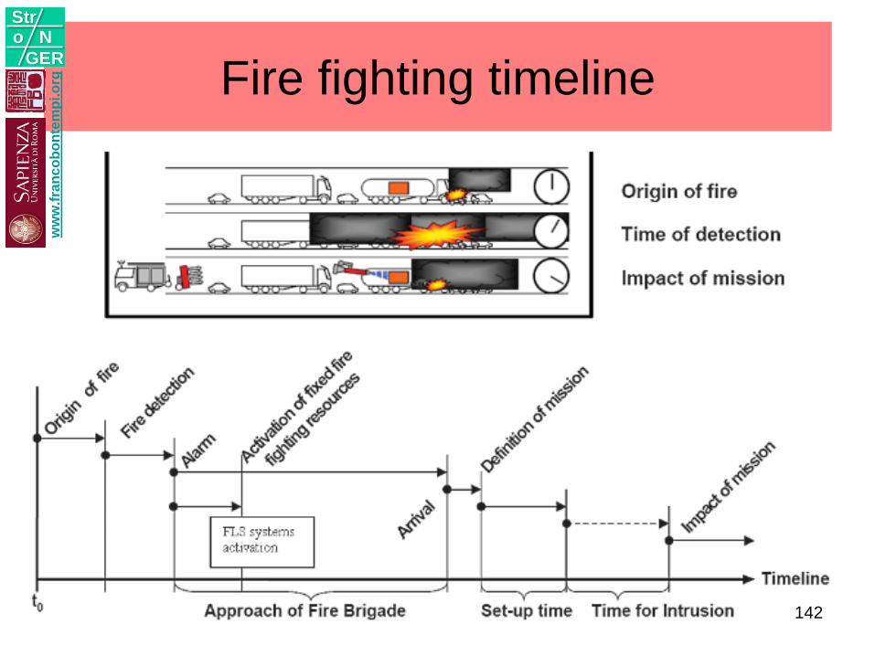
Fire fighting timeline w
ww
.fra
nc
ob
on
tem
pi.o
rg
Stro N
GER
142
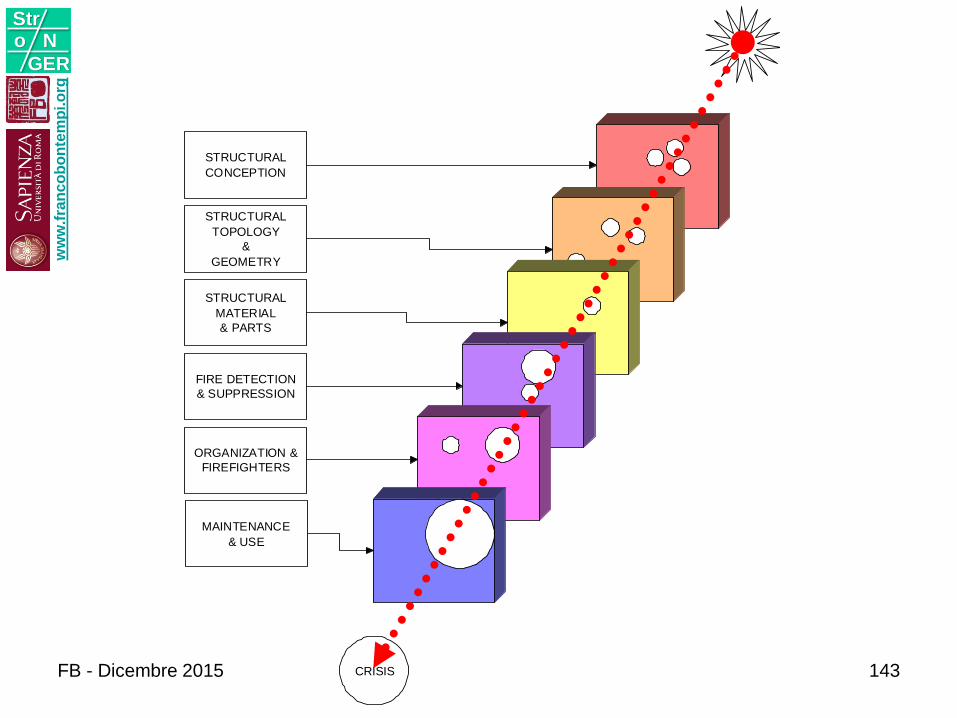
STRUCTURAL
CONCEPTION
STRUCTURAL
TOPOLOGY
&
GEOMETRY
STRUCTURAL
MATERIAL
& PARTS
FIRE DETECTION
& SUPPRESSION
ORGANIZATION &
FIREFIGHTERS
MAINTENANCE
& USE
CRISIS
ww
w.f
ran
co
bo
nte
mp
i.o
rg
Stro N
GER
FB - Dicembre 2015 143
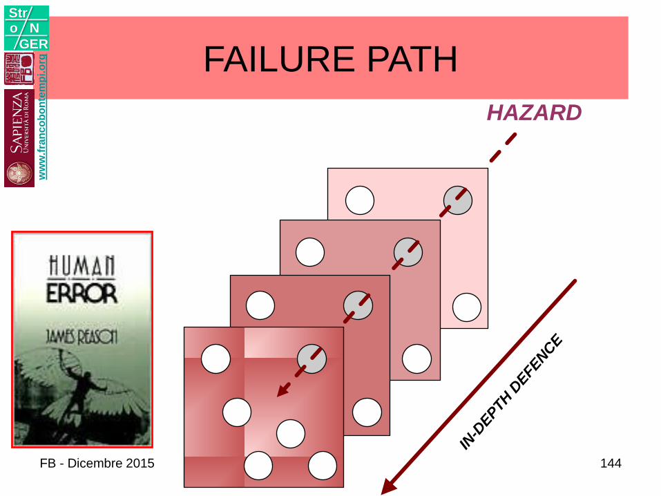
HAZARD
IN-D
EPTH
DEFE
NCE
HOLES DUE TO
ACTIVE ERRORS
HOLES DUE TO
HIDDEN ERRORS
FAILURE PATHw
ww
.fra
nc
ob
on
tem
pi.o
rg
Stro N
GER
FB - Dicembre 2015 144
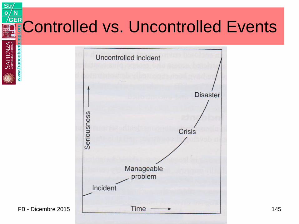
Controlled vs. Uncontrolled Eventsw
ww
.fra
nc
ob
on
tem
pi.o
rg
Stro N
GER
FB - Dicembre 2015 145
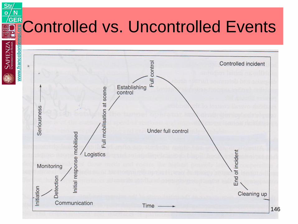
Controlled vs. Uncontrolled Eventsw
ww
.fra
nc
ob
on
tem
pi.o
rg
Stro N
GER
146
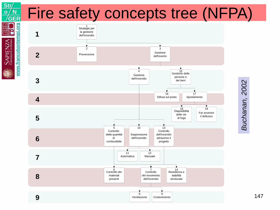
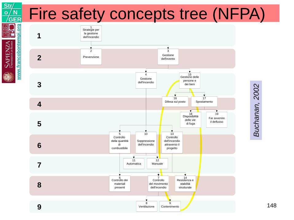
Fire safety concepts tree (NFPA)1
2
3
4
5
6
7
8
9
Buchanan,
2002
Strategie per
la gestione
dell'incendio
1
Prevenzione
2
Gestione
dell'evento
3
Gestione
dell'incendio
4Gestione delle
persone e
dei beni
15
Difesa sul posto
16
Spostamento
17
Disposibilità
delle vie
di fuga
18
Far avvenire
il deflusso
19
Controllo
della quantità
di
combustibile
5
Soppressione
dell'incendio
10Controllo
dell'incendio
attraverso il
progetto
13
Automatica
11
Manuale
12
Controllo dei
materiali
presenti
6Controllo
del movimento
dell'incendio
7Resistenza e
stabilità
strutturale
14
Contenimento
9
Ventilazione
8
ww
w.f
ran
co
bo
nte
mp
i.o
rg
Stro N
GER
147
1
2
3
4
5
6
7
8
9
Strategie per
la gestione
dell'incendio
1
Prevenzione
2
Gestione
dell'evento
3
Gestione
dell'incendio
4Gestione delle
persone e
dei beni
15
Difesa sul posto
16
Spostamento
17
Disposibilità
delle vie
di fuga
18
Far avvenire
il deflusso
19
Controllo
della quantità
di
combustibile
5
Soppressione
dell'incendio
10Controllo
dell'incendio
attraverso il
progetto
13
Automatica
11
Manuale
12
Controllo dei
materiali
presenti
6Controllo
del movimento
dell'incendio
7Resistenza e
stabilità
strutturale
14
Contenimento
9
Ventilazione
8
Fire safety concepts tree (NFPA)
Buchanan,
2002
ww
w.f
ran
co
bo
nte
mp
i.o
rg
Stro N
GER
148
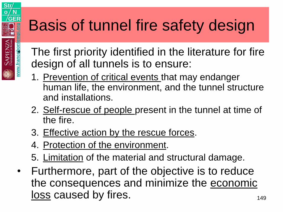
Basis of tunnel fire safety design
• The first priority identified in the literature for fire design of all tunnels is to ensure:1. Prevention of critical events that may endanger
human life, the environment, and the tunnel structure and installations.
2. Self-rescue of people present in the tunnel at time of the fire.
3. Effective action by the rescue forces.
4. Protection of the environment.
5. Limitation of the material and structural damage.
• Furthermore, part of the objective is to reduce the consequences and minimize the economic loss caused by fires.
ww
w.f
ran
co
bo
nte
mp
i.o
rg
Stro N
GER
149
ww
w.f
ran
co
bo
nte
mp
i.o
rg
Stro N
GER
FB - Dicembre 2015 150
RISK CONCERN
ww
w.f
ran
co
bo
nte
mp
i.o
rg
Stro N
GER
FB - Dicembre 2015 Progettazione Strutturale
Antincendio
151
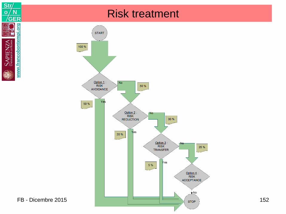
Risk treatmentw
ww
.fra
nc
ob
on
tem
pi.o
rg
Stro N
GER
FB - Dicembre 2015 152
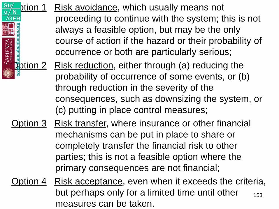
Option 1 Risk avoidance, which usually means not
proceeding to continue with the system; this is not
always a feasible option, but may be the only
course of action if the hazard or their probability of
occurrence or both are particularly serious;
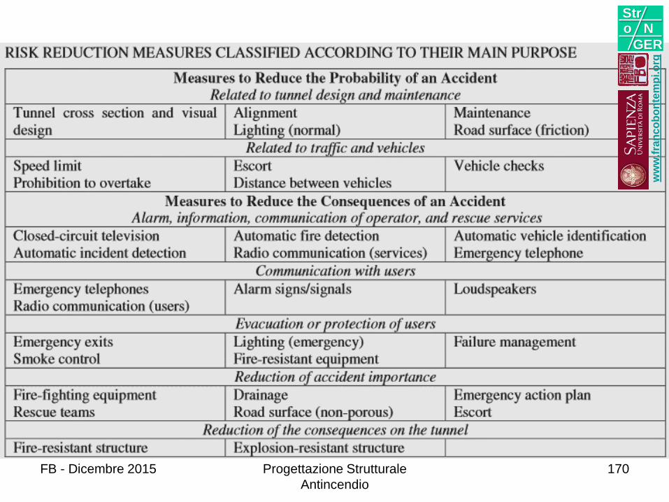
Option 2 Risk reduction, either through (a) reducing the
probability of occurrence of some events, or (b)
through reduction in the severity of the
consequences, such as downsizing the system, or
(c) putting in place control measures;
Option 3 Risk transfer, where insurance or other financial
mechanisms can be put in place to share or
completely transfer the financial risk to other
parties; this is not a feasible option where the
primary consequences are not financial;
Option 4 Risk acceptance, even when it exceeds the criteria,
but perhaps only for a limited time until other
measures can be taken.
ww
w.f
ran
co
bo
nte
mp
i.o
rg
Stro N
GER
153

Quantitative Risk Analysis
Luur,
2002
ww
w.f
ran
co
bo
nte
mp
i.o
rg
Stro N
GER
FB - Dicembre 2015 Progettazione Strutturale
Antincendio
154
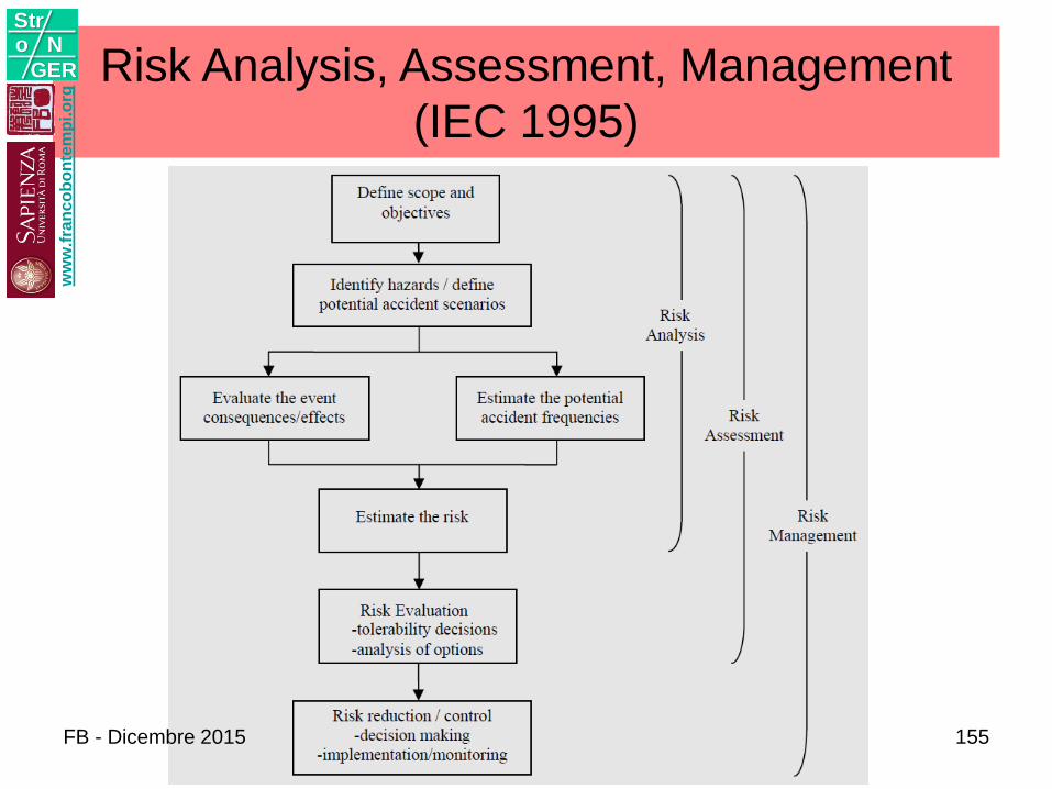
Risk Analysis, Assessment, Management
(IEC 1995)
ww
w.f
ran
co
bo
nte
mp
i.o
rg
Stro N
GER
FB - Dicembre 2015 155
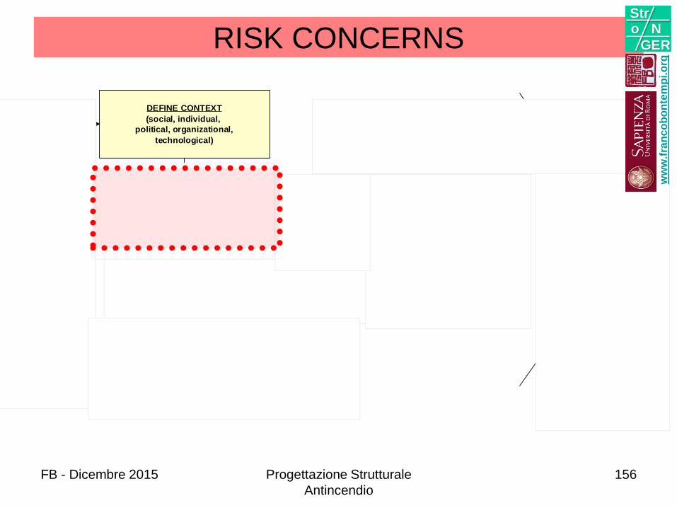
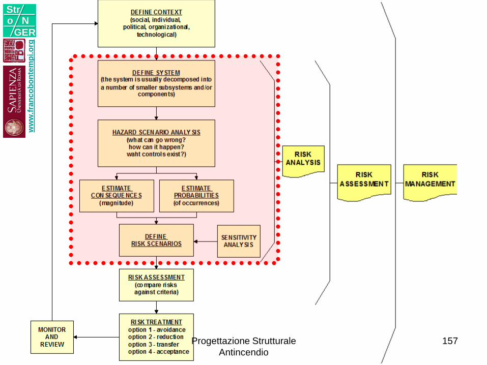
RISK CONCERNS
DEFINE CONTEXT
(social, individual,
political, organizational,
technological)
RSK ANALYSIS
(for the system are defined organization,
scenarios, and consequences of
occurences)
RISK ASSESSMENT
(compare risks
against criteria)
RISK TREATMENT
option 1 - avoidance
option 2 - reduction
option 3 - transfer
option 4 - acceptance
MONITOR
AND
REVIEW
RISK
MANAGEMENT
RISK
ANALYSIS
RISK
ASSESSMENT
ww
w.f
ran
co
bo
nte
mp
i.o
rg
Stro N
GER
FB - Dicembre 2015 Progettazione Strutturale
Antincendio
156
ww
w.f
ran
co
bo
nte
mp
i.o
rg
Stro N
GER
Progettazione Strutturale
Antincendio
157
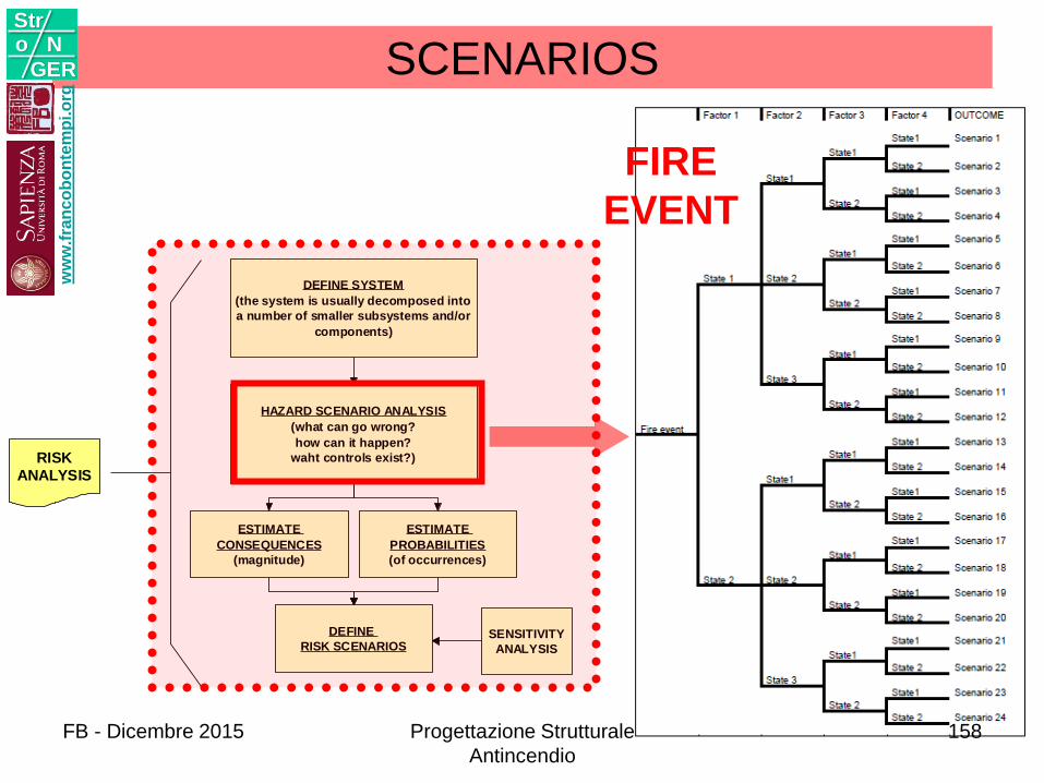
SCENARIOS
DEFINE SYSTEM
(the system is usually decomposed into
a number of smaller subsystems and/or
components)
HAZARD SCENARIO ANALYSIS
(what can go wrong?
how can it happen?
waht controls exist?)
ESTIMATE
CONSEQUENCES
(magnitude)
ESTIMATE
PROBABILITIES
(of occurrences)
DEFINE
RISK SCENARIOS SENSITIVITY
ANALYSIS
RISK
ANALYSIS
FIRE
EVENT
ww
w.f
ran
co
bo
nte
mp
i.o
rg
Stro N
GER
FB - Dicembre 2015 Progettazione Strutturale
Antincendio
158
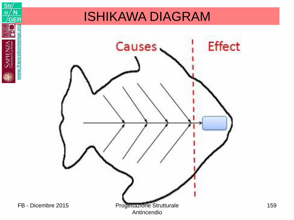
ISHIKAWA DIAGRAMw
ww
.fra
nc
ob
on
tem
pi.o
rg
Stro N
GER
FB - Dicembre 2015 Progettazione Strutturale
Antincendio
159
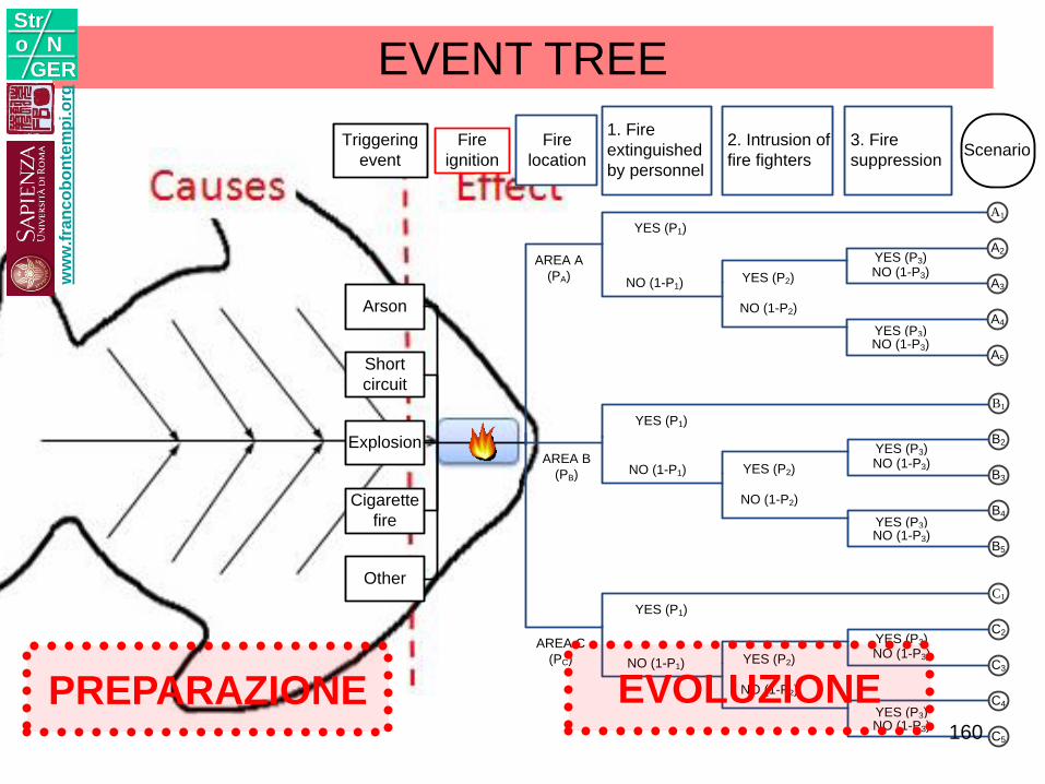
EVENT TREE
Triggering
event
Fire
ignition
1. Fire
extinguished
by personnel
2. Intrusion of
fire fighters
Arson
Explosion
Short
circuit
Cigarette
fire
YES (P1)
NO (1-P1)YES (P2)
NO (1-P2)
Scenario
Other
A1
A2
A3
A4
A5
3. Fire
suppression
YES (P3)NO (1-P3)
YES (P3)NO (1-P3)
Fire
location
AREA A
(PA)
YES (P1)
NO (1-P1) YES (P2)
NO (1-P2)
B1
B2
B3
B4
B5
YES (P3)NO (1-P3)
YES (P3)NO (1-P3)
AREA B
(PB)
YES (P1)
NO (1-P1) YES (P2)
NO (1-P2)
C1
C2
C3
C4
C5
YES (P3)NO (1-P3)
YES (P3)NO (1-P3)
AREA C
(PC)
ww
w.f
ran
co
bo
nte
mp
i.o
rg
Stro N
GER
PREPARAZIONE EVOLUZIONE160
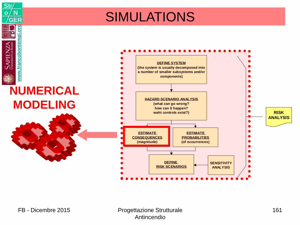
DEFINE SYSTEM
(the system is usually decomposed into
a number of smaller subsystems and/or
components)
HAZARD SCENARIO ANALYSIS
(what can go wrong?
how can it happen?
waht controls exist?)
ESTIMATE
CONSEQUENCES
(magnitude)
ESTIMATE
PROBABILITIES
(of occurrences)
DEFINE
RISK SCENARIOS SENSITIVITY
ANALYSIS
RISK
ANALYSIS
NUMERICAL
MODELING
SIMULATIONSw
ww
.fra
nc
ob
on
tem
pi.o
rg
Stro N
GER
FB - Dicembre 2015 Progettazione Strutturale
Antincendio
161
ww
w.f
ran
co
bo
nte
mp
i.o
rg
Stro N
GER
FB - Dicembre 2015 Progettazione Strutturale
Antincendio
162
ww
w.f
ran
co
bo
nte
mp
i.o
rg
Stro N
GER
FB - Dicembre 2015 Progettazione Strutturale
Antincendio
163
ww
w.f
ran
co
bo
nte
mp
i.o
rg
Stro N
GER
FB - Dicembre 2015 Progettazione Strutturale
Antincendio
164
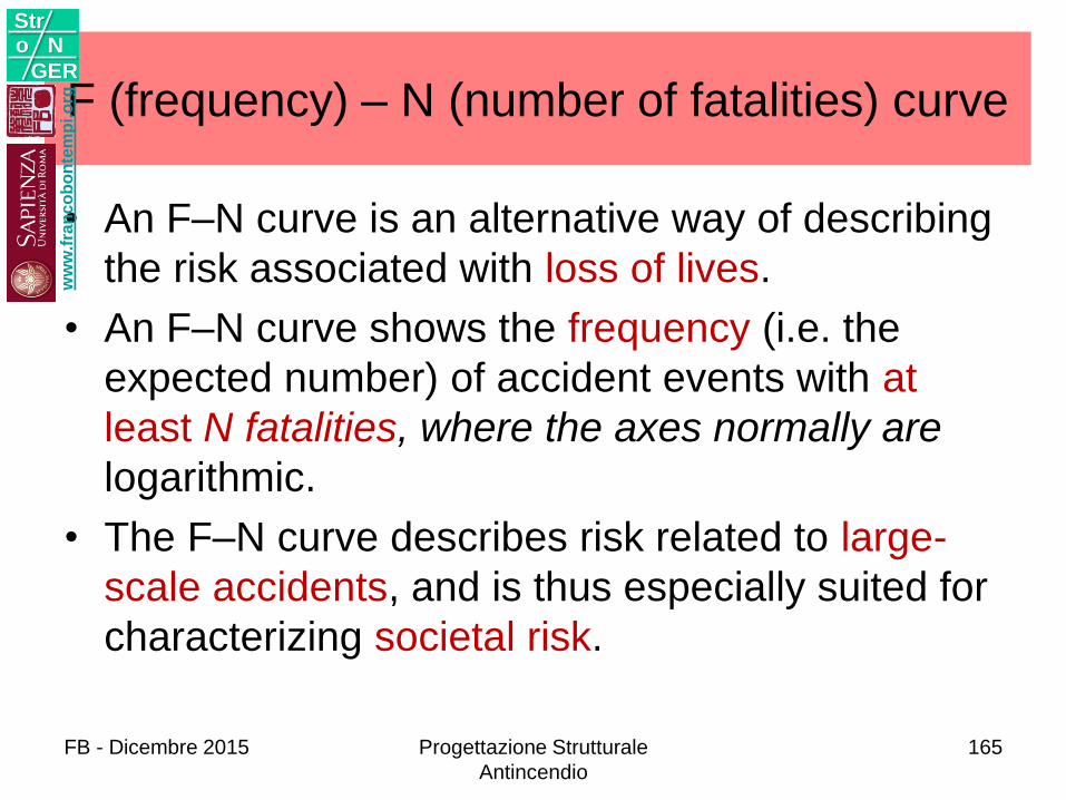
F (frequency) – N (number of fatalities) curve
• An F–N curve is an alternative way of describing
the risk associated with loss of lives.
• An F–N curve shows the frequency (i.e. the
expected number) of accident events with at
least N fatalities, where the axes normally are
logarithmic.
• The F–N curve describes risk related to large-
scale accidents, and is thus especially suited for
characterizing societal risk.
ww
w.f
ran
co
bo
nte
mp
i.o
rg
Stro N
GER
FB - Dicembre 2015 Progettazione Strutturale
Antincendio
165
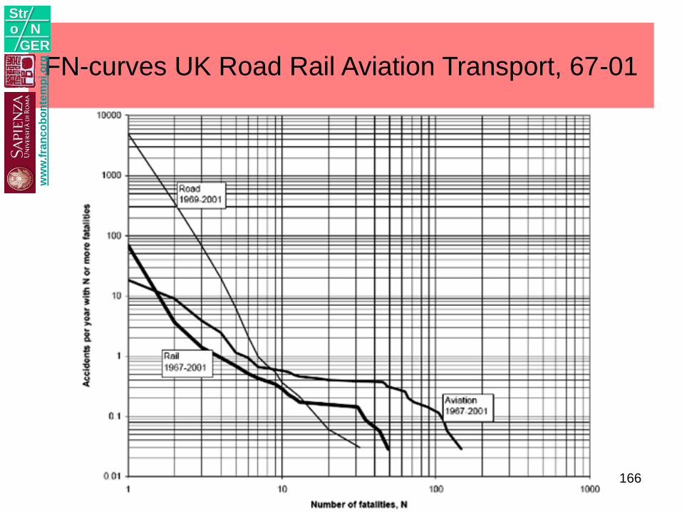
FN-curves UK Road Rail Aviation Transport, 67-01w
ww
.fra
nc
ob
on
tem
pi.o
rg
Stro N
GER
166
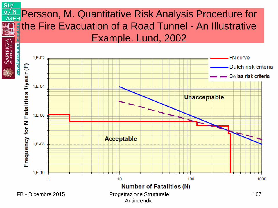
Persson, M. Quantitative Risk Analysis Procedure for
the Fire Evacuation of a Road Tunnel - An Illustrative
Example. Lund, 2002
ww
w.f
ran
co
bo
nte
mp
i.o
rg
Stro N
GER
FB - Dicembre 2015 Progettazione Strutturale
Antincendio
167
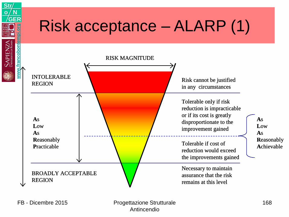
Risk acceptance – ALARP (1)
RISK MAGNITUDE
INTOLERABLE
REGION
As
Low
As
Reasonably
Practicable
BROADLY ACCEPTABLE
REGION
Risk cannot be justified
in any circumstances
Tolerable only if risk
reduction is impracticable
or if its cost is greatly
disproportionate to the
improvement gained
Tolerable if cost of
reduction would exceed
the improvements gained
Necessary to maintain
assurance that the risk
remains at this level
As
Low
As
Reasonably
Achievable
ww
w.f
ran
co
bo
nte
mp
i.o
rg
Stro N
GER
FB - Dicembre 2015 Progettazione Strutturale
Antincendio
168
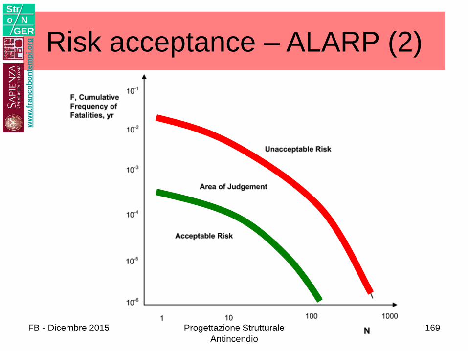
Risk acceptance – ALARP (2)w
ww
.fra
nc
ob
on
tem
pi.o
rg
Stro N
GER
FB - Dicembre 2015 Progettazione Strutturale
Antincendio
169
ww
w.f
ran
co
bo
nte
mp
i.o
rg
Stro N
GER
FB - Dicembre 2015 Progettazione Strutturale
Antincendio
170
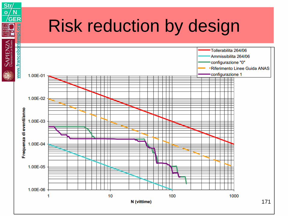
Risk reduction by designw
ww
.fra
nc
ob
on
tem
pi.o
rg
Stro N
GER
171
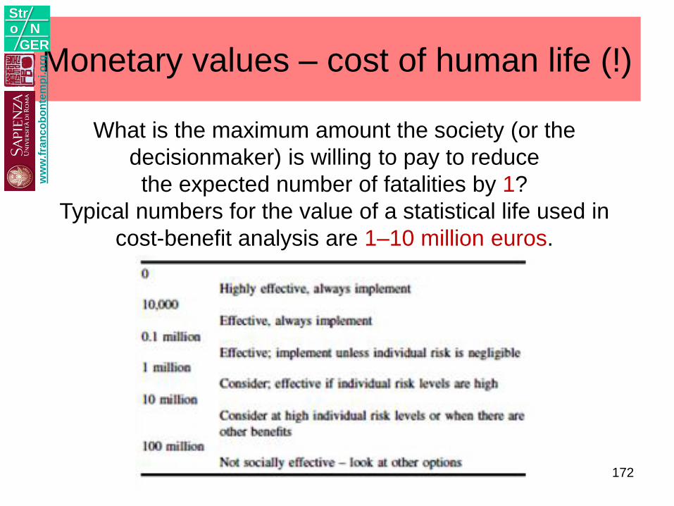
Monetary values – cost of human life (!)
What is the maximum amount the society (or the
decisionmaker) is willing to pay to reduce
the expected number of fatalities by 1?
Typical numbers for the value of a statistical life used in
cost-benefit analysis are 1–10 million euros.
ww
w.f
ran
co
bo
nte
mp
i.o
rg
Stro N
GER
172
RESISTENZA
6w
ww
.fra
nc
ob
on
tem
pi.o
rg
Stro N
GER
FB - Dicembre 2015 Progettazione Strutturale
Antincendio
173
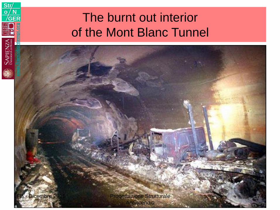
The burnt out interior
of the Mont Blanc Tunnel
ww
w.f
ran
co
bo
nte
mp
i.o
rg
Stro N
GER
FB - Dicembre 2015 Progettazione Strutturale
Antincendio
174
Curve temperatura - tempo
ww
w.f
ran
co
bo
nte
mp
i.o
rg
Stro N
GER
FB - Dicembre 2015 Progettazione Strutturale
Antincendio
175
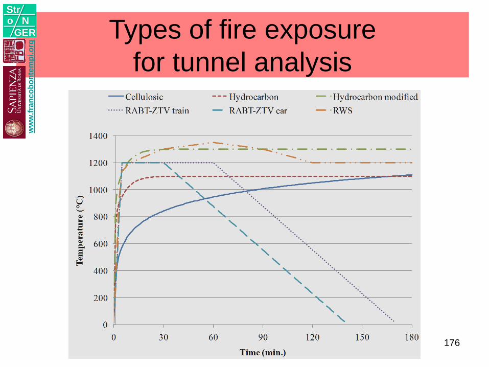
Types of fire exposure
for tunnel analysis
ww
w.f
ran
co
bo
nte
mp
i.o
rg
Stro N
GER
176
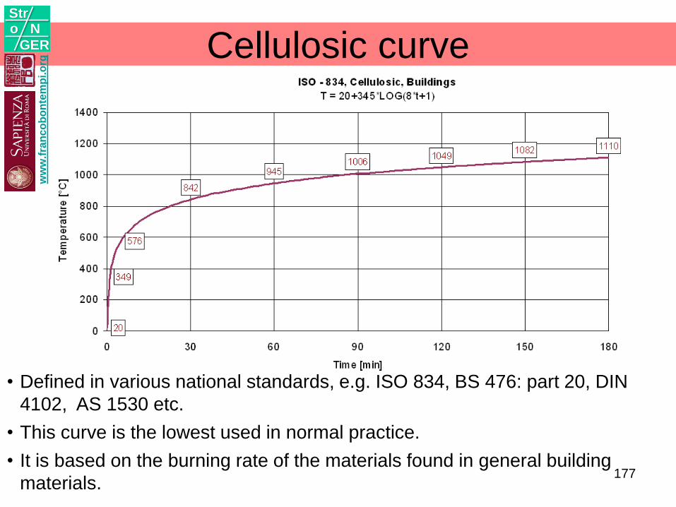
Cellulosic curve
• Defined in various national standards, e.g. ISO 834, BS 476: part 20, DIN
4102, AS 1530 etc.
• This curve is the lowest used in normal practice.
• It is based on the burning rate of the materials found in general building
materials.
ww
w.f
ran
co
bo
nte
mp
i.o
rg
Stro N
GER
177
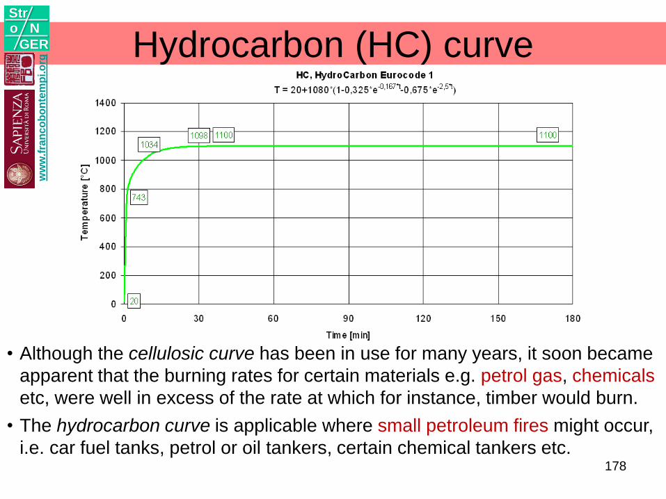
Hydrocarbon (HC) curve
• Although the cellulosic curve has been in use for many years, it soon became
apparent that the burning rates for certain materials e.g. petrol gas, chemicals
etc, were well in excess of the rate at which for instance, timber would burn.
• The hydrocarbon curve is applicable where small petroleum fires might occur,
i.e. car fuel tanks, petrol or oil tankers, certain chemical tankers etc.
ww
w.f
ran
co
bo
nte
mp
i.o
rg
Stro N
GER
178
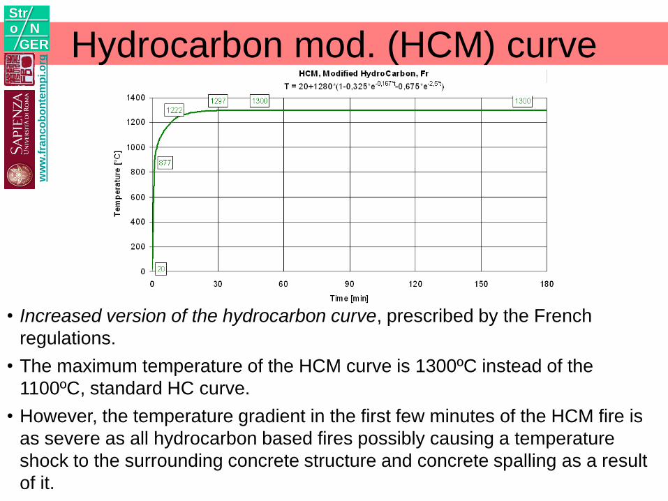
Hydrocarbon mod. (HCM) curve
• Increased version of the hydrocarbon curve, prescribed by the French
regulations.
• The maximum temperature of the HCM curve is 1300ºC instead of the
1100ºC, standard HC curve.
• However, the temperature gradient in the first few minutes of the HCM fire is
as severe as all hydrocarbon based fires possibly causing a temperature
shock to the surrounding concrete structure and concrete spalling as a result
of it.
ww
w.f
ran
co
bo
nte
mp
i.o
rg
Stro N
GER
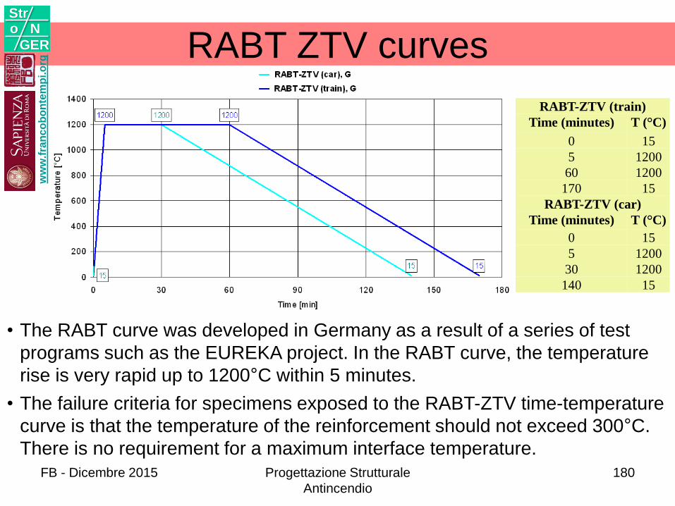
RABT ZTV curves
• The RABT curve was developed in Germany as a result of a series of test
programs such as the EUREKA project. In the RABT curve, the temperature
rise is very rapid up to 1200°C within 5 minutes.
• The failure criteria for specimens exposed to the RABT-ZTV time-temperature
curve is that the temperature of the reinforcement should not exceed 300°C.
There is no requirement for a maximum interface temperature.
RABT-ZTV (train)
Time (minutes) T (°C)
0 15
5 1200
60 1200
170 15
RABT-ZTV (car)
Time (minutes) T (°C)
0 15
5 1200
30 1200
140 15
ww
w.f
ran
co
bo
nte
mp
i.o
rg
Stro N
GER
FB - Dicembre 2015 Progettazione Strutturale
Antincendio
180
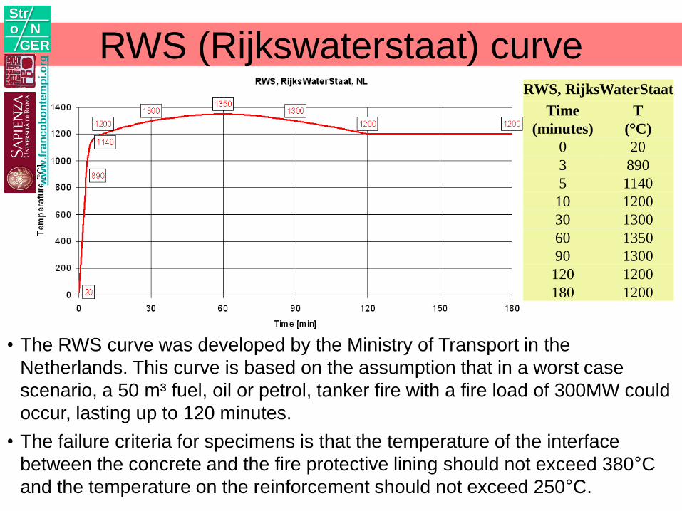
RWS (Rijkswaterstaat) curve
• The RWS curve was developed by the Ministry of Transport in the
Netherlands. This curve is based on the assumption that in a worst case
scenario, a 50 m³ fuel, oil or petrol, tanker fire with a fire load of 300MW could
occur, lasting up to 120 minutes.
• The failure criteria for specimens is that the temperature of the interface
between the concrete and the fire protective lining should not exceed 380°C
and the temperature on the reinforcement should not exceed 250°C.
RWS, RijksWaterStaat
Time
(minutes)
T
(°C)
0 20
3 890
5 1140
10 1200
30 1300
60 1350
90 1300
120 1200
180 1200
ww
w.f
ran
co
bo
nte
mp
i.o
rg
Stro N
GER
ww
w.f
ran
co
bo
nte
mp
i.o
rg
Stro N
GER
ww
w.f
ran
co
bo
nte
mp
i.o
rg
Stro N
GER
FB - Dicembre 2015 Progettazione Strutturale
Antincendio
183
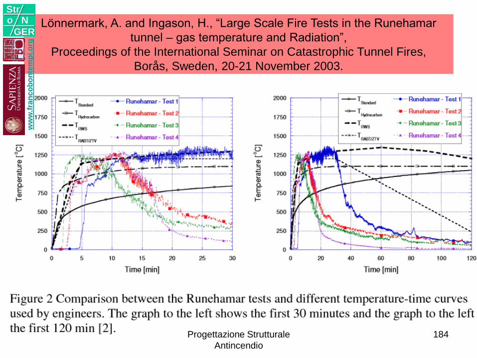
Lönnermark, A. and Ingason, H., “Large Scale Fire Tests in the Runehamar
tunnel – gas temperature and Radiation”,
Proceedings of the International Seminar on Catastrophic Tunnel Fires,
Borås, Sweden, 20-21 November 2003.
ww
w.f
ran
co
bo
nte
mp
i.o
rg
Stro N
GER
Progettazione Strutturale
Antincendio
184
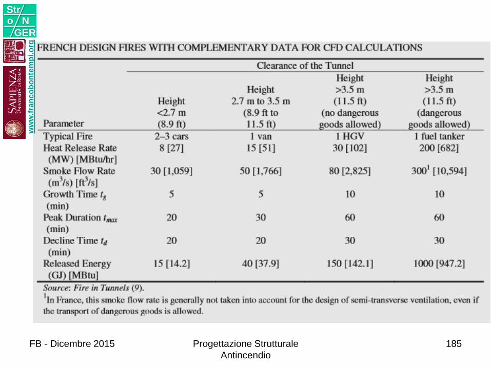
ww
w.f
ran
co
bo
nte
mp
i.o
rg
Stro N
GER
185Progettazione Strutturale
Antincendio
FB - Dicembre 2015
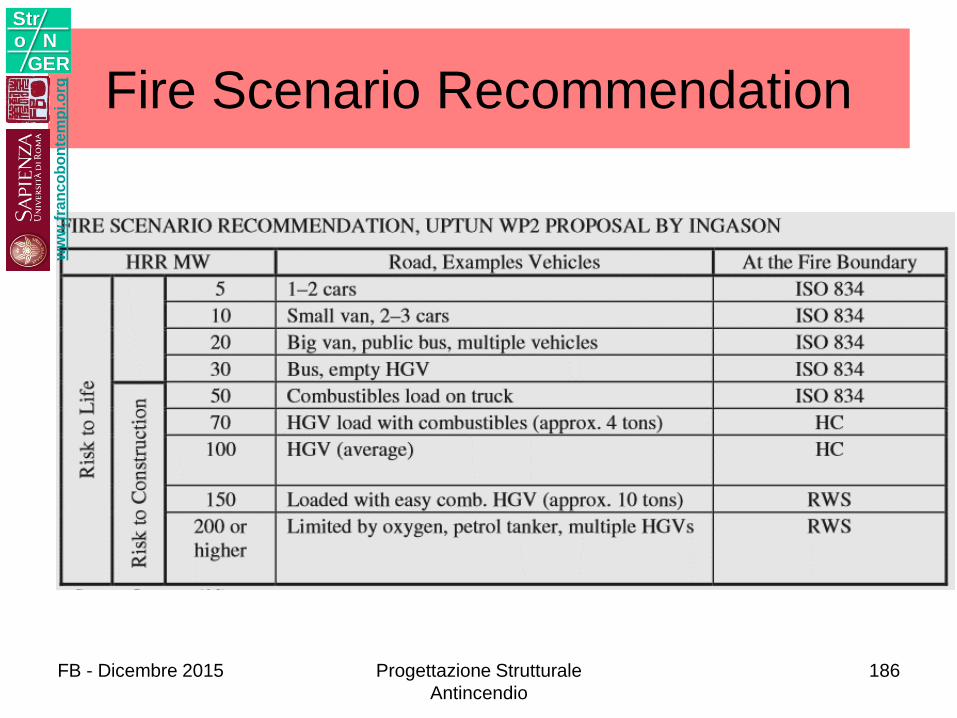
Fire Scenario Recommendationw
ww
.fra
nc
ob
on
tem
pi.o
rg
Stro N
GER
FB - Dicembre 2015 Progettazione Strutturale
Antincendio
186
Verifiche
ww
w.f
ran
co
bo
nte
mp
i.o
rg
Stro N
GER
FB - Dicembre 2015 Progettazione Strutturale
Antincendio
187
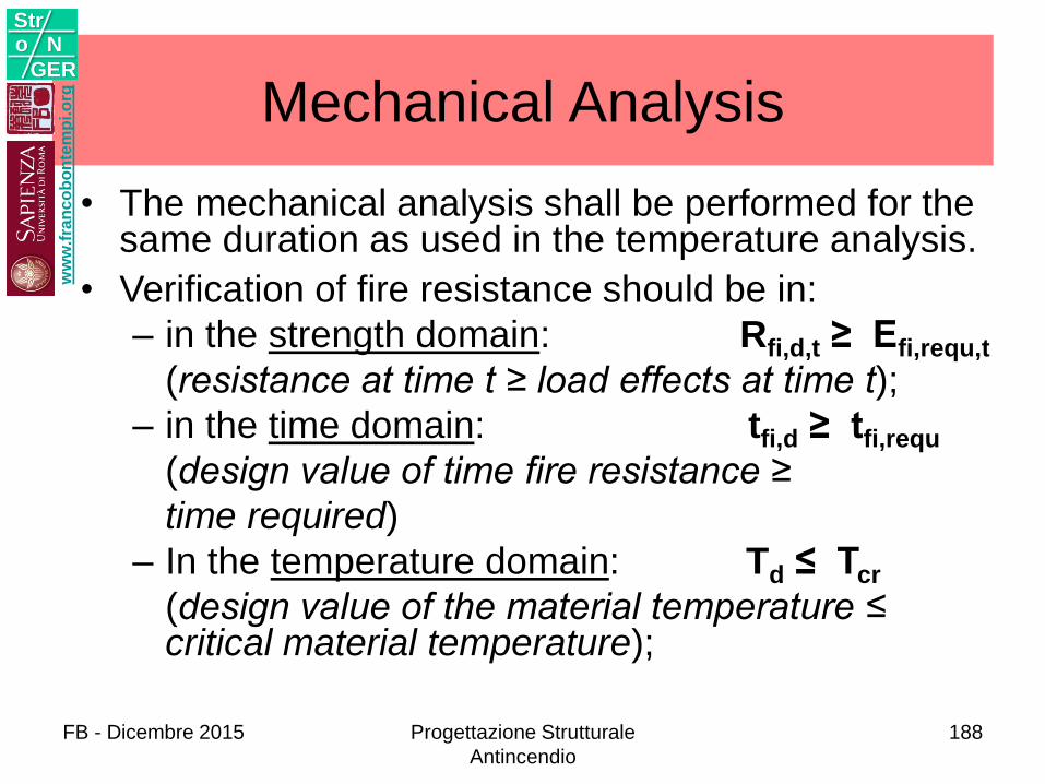
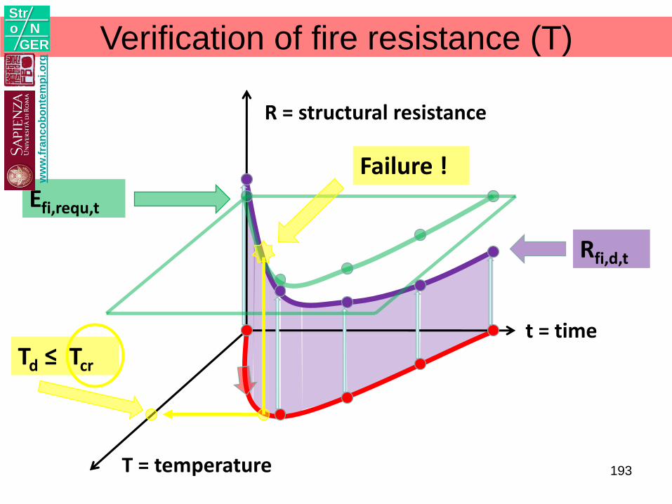
Mechanical Analysis
• The mechanical analysis shall be performed for the same duration as used in the temperature analysis.
• Verification of fire resistance should be in:
– in the strength domain: Rfi,d,t ≥ Efi,requ,t
(resistance at time t ≥ load effects at time t);
– in the time domain: tfi,d ≥ tfi,requ
(design value of time fire resistance ≥
time required)
– In the temperature domain: Td ≤ Tcr
(design value of the material temperature ≤ critical material temperature);
ww
w.f
ran
co
bo
nte
mp
i.o
rg
Stro N
GER
FB - Dicembre 2015 Progettazione Strutturale
Antincendio
188
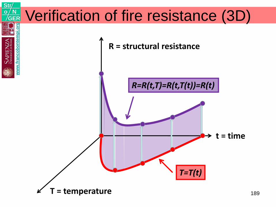
Verification of fire resistance (3D)
R = structural resistance
T = temperature
t = time
T=T(t)
R=R(t,T)=R(t,T(t))=R(t)
ww
w.f
ran
co
bo
nte
mp
i.o
rg
Stro N
GER
189
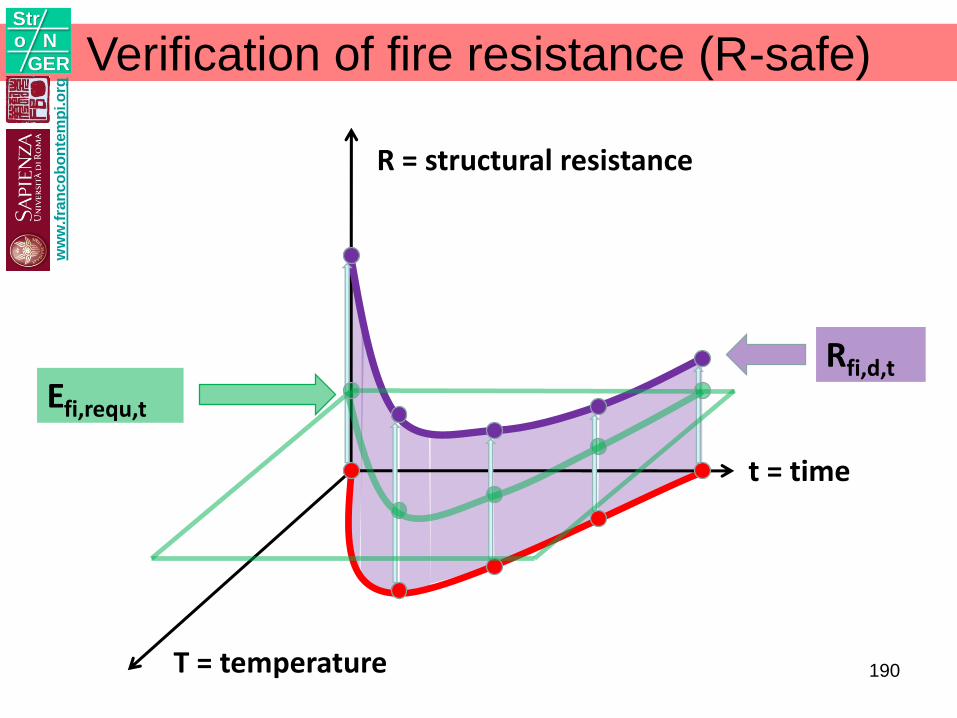
Verification of fire resistance (R-safe)
R = structural resistance
T = temperature
t = time
Rfi,d,t
Efi,requ,t
ww
w.f
ran
co
bo
nte
mp
i.o
rg
Stro N
GER
190
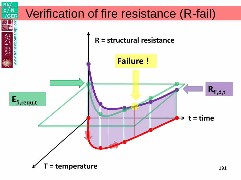
Verification of fire resistance (R-fail)
R = structural resistance
T = temperature
t = time
Efi,requ,t
Rfi,d,t
Failure !ww
w.f
ran
co
bo
nte
mp
i.o
rg
Stro N
GER
191
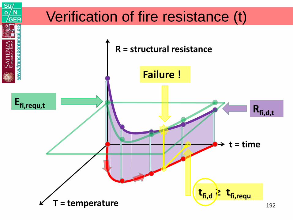
Verification of fire resistance (t)
R = structural resistance
T = temperature
t = time
Efi,requ,t Rfi,d,t
Failure !
tfi,d ≥ tfi,requ
ww
w.f
ran
co
bo
nte
mp
i.o
rg
Stro N
GER
192
Verification of fire resistance (T)
R = structural resistance
T = temperature
t = time
Efi,requ,t
Rfi,d,t
Failure !
Td ≤ Tcr
ww
w.f
ran
co
bo
nte
mp
i.o
rg
Stro N
GER
193
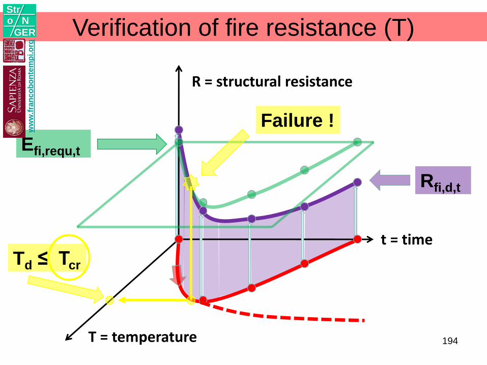
Verification of fire resistance (T)
R = structural resistance
T = temperature
t = time
Efi,requ,t
Rfi,d,t
Failure !
Td ≤ Tcr
ww
w.f
ran
co
bo
nte
mp
i.o
rg
Stro N
GER
194
ww
w.f
ran
co
bo
nte
mp
i.o
rg
Stro N
GER
FB - Dicembre 2015 Progettazione Strutturale
Antincendio
195
ww
w.f
ran
co
bo
nte
mp
i.o
rg
Stro N
GER
FB - Dicembre 2015 Progettazione Strutturale
Antincendio
196
CONCLUSIONIConceptual design
Resilience
7w
ww
.fra
nc
ob
on
tem
pi.o
rg
Stro N
GER
FB - Dicembre 2015 Progettazione Strutturale
Antincendio
197
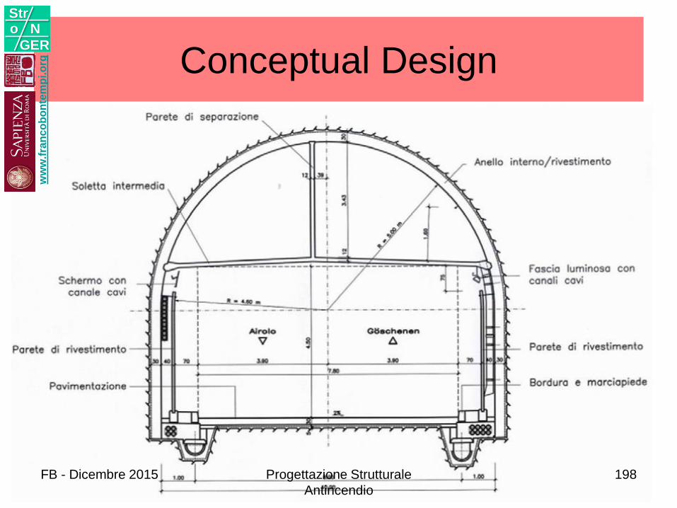
Conceptual Designw
ww
.fra
nc
ob
on
tem
pi.o
rg
Stro N
GER
FB - Dicembre 2015 Progettazione Strutturale
Antincendio
198
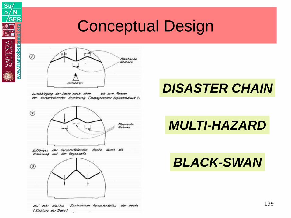
Conceptual Design
MULTI-HAZARD
BLACK-SWAN
DISASTER CHAIN
ww
w.f
ran
co
bo
nte
mp
i.o
rg
Stro N
GER
199
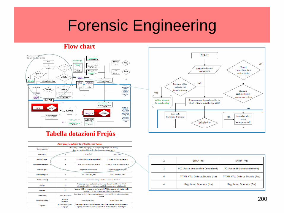
Flow chart
Tabella dotazioni Frejùs
Forensic Engineering
200
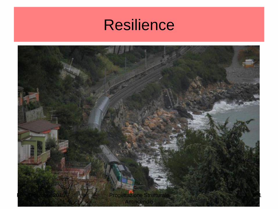
Resilience
FB - Dicembre 2015 Progettazione Strutturale
Antincendio
201
Resilience
• Resilience is defined as “the positive
ability of a system or company to adapt
itself to the consequences of a
catastrophic failure caused by power
outage, a fire, a bomb or similar” event or
as "the ability of a system to cope with
change".
ww
w.f
ran
co
bo
nte
mp
i.o
rg
Stro N
GER
FB - Dicembre 2015 Progettazione Strutturale
Antincendio
202
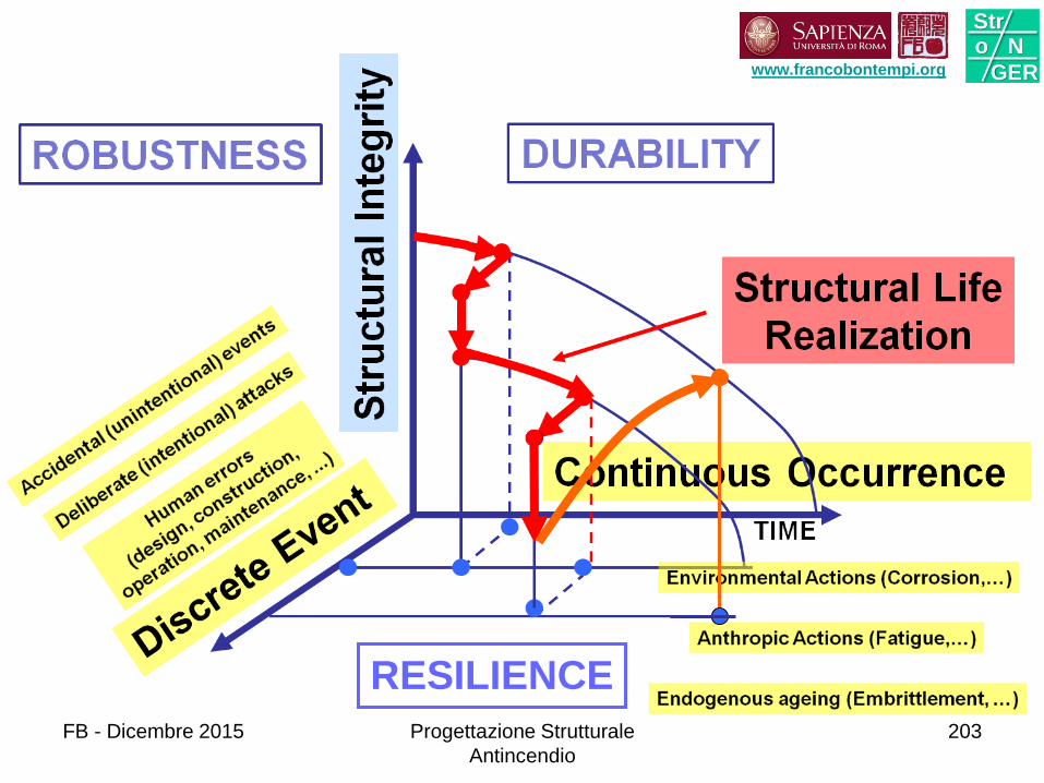
RESILIENCE
www.francobontempi.org
Stro N
GER
FB - Dicembre 2015 Progettazione Strutturale
Antincendio
203
ACKNOWLEDGEMENTS
• Dr. Konstantinos GKOUMAS – Uniroma1
• Dr. Francesco PETRINI – Uniroma1
• Ing. Alessandra LO CANE – MIT
• Dr. Filippo GENTILI – Coimbra (PT)
• Mr. Tiziano BARONCELLI – Uniroma1
ww
w.f
ran
co
bo
nte
mp
i.o
rg
Stro N
GER
FB - Dicembre 2015 Progettazione Strutturale
Antincendio
204
205205
Stro N
GERwww.stronger2012.com
FB - Dicembre 2015 Progettazione Strutturale
Antincendio
205