PMA PMA/C prestazioni dei ventilatori indicati nelle tabelle, del presente catalogo, sono ottenute...
35
Ducted axial fans Ventilatori assiali intubati PMA PMA/C TS SERIES
Transcript of PMA PMA/C prestazioni dei ventilatori indicati nelle tabelle, del presente catalogo, sono ottenute...
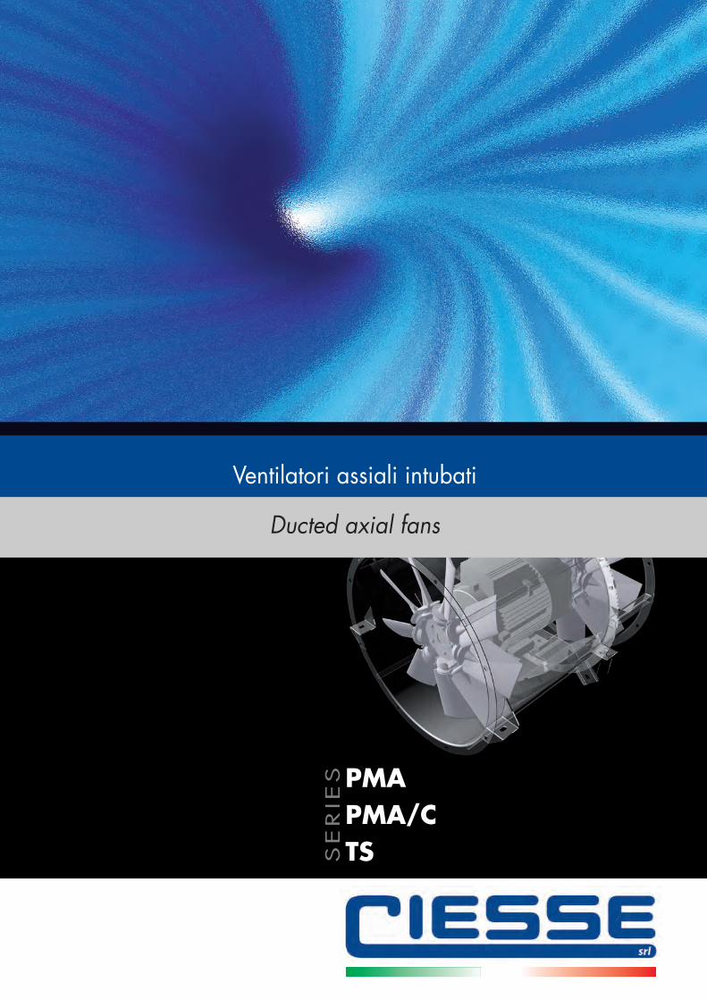
Ducted axial fans
Ventilatori assiali intubati
PMAPMA/CTSS
ER
IES
copertina_Layout 1 18/05/12 10.35 Pagina 1
100% made in Italy1
23
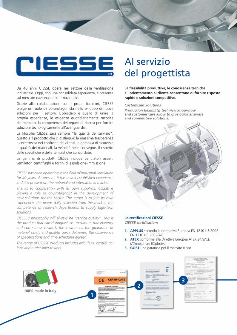
Da 40 anni CIESSE opera nel settore della ventilazione industriale. Oggi, con una consolidata esperienza, è presente sul mercato nazionale e internazionale.
Grazie alla collaborazione con i propri fornitori, CIESSE svolge un ruolo da co-protagonista nello sviluppo di nuove soluzioni per il settore. L’obiettivo è quello di unire la propria esperienza, le esigenze quotidianamente raccolte dal mercato, la competenza dei reparti di ricerca per fornire soluzioni tecnologicamente all’avanguardia.
La filosofia CIESSE sarà sempre “la qualità del servizio”; questo è il prodotto che ci distingue: la massima trasparenza e correttezza nei confronti dei clienti, la garanzia di sicurezza e qualità dei materiali, la velocità nelle consegne, il rispetto delle specifiche e delle tempistiche concordate.
La gamma di prodotti CIESSE include ventilatori assiali, ventilatori centrifughi e torrini di espulsione-immissione.
CIESSE has been operating in the field of industrial ventilation for 40 years. At present, it has a well-established experience and it is present on the national and international market.
Thanks to cooperation with its own suppliers, CIESSE is playing a role as co-protagonist in the development of new solutions for the sector. The target is to join its own experience, the needs daily collected from the market, the competence of research departments to supply high-tech solutions.
CIESSE’s philosophy will always be “service quality”. This is the product that can distinguish us: maximum transparency and correctness towards the customers, the guarantee of material safety and quality, quick deliveries, the observance of specifications and time schedules agreed.
The range of CIESSE products includes axial fans, centrifugal fans and outlet-inlet towers.
Le certificazioni CIESSECIESSE certifications 1. APPLUS secondo la normativa Europea EN 12101-3:2002
EN 12101-3:2002/AC2. ATEX conforme alla Direttiva Europea ATEX 94/9/CE
(ATmosphere EXplosive)3. GOST una garanzia per il mercato russo
Al servizio del progettistaLa flessibilità produttiva, le conoscenze tecniche e l’orientamento al cliente consentono di fornire risposte rapide e soluzioni competitive.
Costomized SolutionsProduction flexibility, technical know-how and customer care allow to give quick answers and competitive solutions.
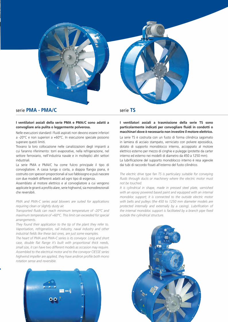
serie PMA - PMA/C
I ventilatori assiali della serie PMA e PMA/C sono adatti a convogliare aria pulita o leggermente polverosa.
Nelle esecuzioni standard i fluidi aspirati non devono essere inferiori a -20°C e non superiori a +60°C. In esecuzione speciale possono superare questi limiti.Trovano la loro collocazione nelle canalizzazioni degli impianti a cui faranno riferimento: torri evaporative, nella refrigerazione, nel settore ferroviario, nell’industria navale e in molteplici altri settori industriali.La serie PMA e PMA/C ha come fulcro principale il tipo di convogliatore. A cassa lunga o corta, a doppia flangia piana, è costruito con spessori proporzionali al suo fabbisogno e può nascere con due modelli differenti adatti ad ogni tipo di esigenza.Assemblato al motore elettrico e al convogliatore a cui vengono applicate le giranti a profilo alare, serie highwind, sia monodirezionali che reversibili.
PMA and PMA-C series axial blowers are suited for applications requiring clean or slightly dusty air.Transported fluids can reach minimum temperature of -20°C and maximum temperature of +60°C. This limit can exceeded for special arrangements. They found their application to the tip of the plant they refer to. Vaporisation, refrigeration, rail industry, naval industry and other industrial fields like these last ones, are just some examples.The heart of PMA and PMA-C series is its conveyor. Long and short case, double flat flange it’s built with proportional thick needs, small size, it can have two different models as occasion may require.Assembled to the electrical motor and to the conveyor CIESSE series highwind impeller are applied, they have andiron profile both mono rotation sense and reversible.
serie TS
I ventilatori assiali a trasmissione della serie TS sono particolarmente indicati per convogliare fluidi in condotti o macchinari dove è necessario non investire il motore elettrico.
La serie TS è costruita con un fusto di forma cilindrica sagomato in lamiera di acciaio stampato, verniciato con polvere epossidica, dotato di supporto monoblocco interno, accoppiato al motore elettrico esterno per mezzo di cinghie e pulegge (protette da carter interno ed esterno nei modelli di diametro da 450 a 1250 mm).La lubrificazione del supporto monoblocco interno è resa agevole dai tubi di raccordo fissati all’esterno del fusto cilindrico.
The electric drive type fan TS is particulary suitable for conveying fluids through ducts or machinery where the electric motor must not be touched.It is cylindrical in shape, made in pressed steel plate, varnished with an epoxy powered based paint and equipped with an internal monobloc support; it is connected to the outside electric motor with belts and pulleys (the 450 to 1250 mm diameter models are protected internally and externally by a casing). Lubrification of the internal monobloc support is facilitated by a branch pipe fixed outside the cylindrical structure.
Le prestazioni dei ventilatori indicati nelle tabelle, del presente catalogo,
sono ottenute da prove secondo specifiche normative, eseguite con
tubo di prova, dotato di diaframmi di vario diametro collocati sulla
mandata del ventilatore, con la temperatura dell’aria a 15°C e pressione
barometrica di 760 mmHg.
Ogni singola girante è stata equilibrata dinamicamente e staticamente,
collaudata per le varie inclinazioni disponibili secondo le norme UNI 1940.
I valori di potenza assorbita delle giranti, sono misurati sui motori
elettrici direttamente accoppiati, a velocità costante, per il massimo
rendimento.
I valori di livello sonoro sono riferiti alla media matematica di piu letture,
effettuate a 45° dall’asse del motore, ad una distanza pari a 3 volte il
diametro della girante.
A corredo è possibile fornire diversi accessori come: n controflange
n reti protettive secondo norme UNI 9219
n serrande a gravità e motorizzate
n variatori di velocita monofase e trifase
n basi d’appoggio
n giunti antivibranti
n silenziatori
n boccagli aspiranti
Fans performances tabulate in this catalogue, are obtained by reliability tests, with different diaphgram diameter pipe, placed on the fan delivery using 15°C air temperature and 760 mmHg.Every single blades impeller has been dynamically and statistically balance and tested for each inclination according to UNI 1940 regulation.Power absorbed by impellers is measured on directly driven motors at maximum efficiency level. Sound levels refer to the average reading of the 45° from the motor axle, at a distance of three times the diameter of the impeller.
It is possible to supply several accessories for our fans as against flanges, protective nets, following the rule UNI 9219, motorized gravity-fed rolling shutters, speed variators mono phase and three phase system, bases, anti-vibration joints, silencer and inlet cone.
I ventilatori assiali CIESSE sono realizzati per trasportare e movimentare piccoli e grandi volumi d’aria, a bassa e media pressione. Sono dotati di mozzo pressofuso in alluminio e giranti brevettate con pale ad inclinazione variabile per modificarne le prestazioni in funzione delle esigenze richieste.
In relazione alle temperature ed ai fluidi aspirati il materiale delle pale sarà differente:
n PPG (polipropilene) per temperature d’esercizio da -10°C a +90°Cn NYV (nylon vetro) per temperature d’esercizio da -40°C a +120°Cn ALL (allumino) per temperature d’esercizio da -55°C a +250°Cn PAGAS (antistatico e anticonducibile) per esecuzioni ATEX da -40°C a +110°Cn Fe 360 (acciaio al carbonio) per temperature d’esercizio da -40°C a +400°C / 2h
Axial fans by CIESSE are suited for movingand carrying small and high air flow rates, with low and medium pressure. They are provided with patent impellers made of aluminium and pressure die-cast hub with variable inclination blades to change the performances as occasion may require.
According to the temperatures and the types of transported fluids, propeller blade material may be different:• PPG (polypropylene) for temperature from -10°C to +90°C• NYV (nylon vetro) for temperature from -40°C to +120°C• ALL (aluminum) for temperature from -55°C to +250°C• PAGAS (anti-static and anti-conductive) for ATEX executions -40°C to +110°C• Fe 360 (carbon steel) for temperature from -40°C to +400°C / 2h
Nozioni tecniche Technical infomations
CIESSE © 2012CIESSE si riserva il diritto di modificare, senza alcun preavviso, i dati riportati nella presente documentazione.CIESSE reserves right to modify reported data without any notification.
Caratteristiche Tecniche Technical characteristics
Diametro Ventilatore Fan’s Diameter [mm]
Portata d’Aria Air Flow Rate [m3/h]
Pressione Statica a T. 20°C Statical Pressure [mmH2O; Pa]
Pressione Totale a T. 20°C Total Pressure [mmH2O; Pa]
Tipo fluido trattatoFlow type
(es. presenza agenti chimici, aria polverosa)(ex. chemical agents, dusty air)
Temperatura di esercizio fluido Working Temperature [°C] (std. -20°C +60°C)
N° Giri Ventola N° Impeller Tours [rpm] (Solo Trasmissione)
Livello Pressione/Potenza Sonora Pressure/Power Sound Level [dBA]
Materiale Girante Impeller Material PPG - PAG - PAGAS - ALL - Fe 360
Rotazione Rotation Sense
Oraria - AntiorariaHoraire - Antihoraire
Motore Motor
Potenza motore installato Motor Power [Kw]
Classe e Isolamento Motore IP Protection (std. F/IP55)
Frequenza Frequence [Hz] (es. 50 Hz / 60 Hz)
Tensione Tension[V] (es. 3Ph. Eurotensione 230/400V)
N° Poli N° Poles [rpm]
Zona Atex Atex zone (vedi pag. 28) (see page 28)
Convogliatore Conveyor
Materiale Material Fe 360 - AISI 304 - AISI 316
Portello d’ispezione Inspection door (> d. 450)
Modello Cassa Case Type PMA - PMA/C (vedi pag. 7) (see page 7)
N° Reti di Protezione Screen protection N°
Forature Holes DIN 24154
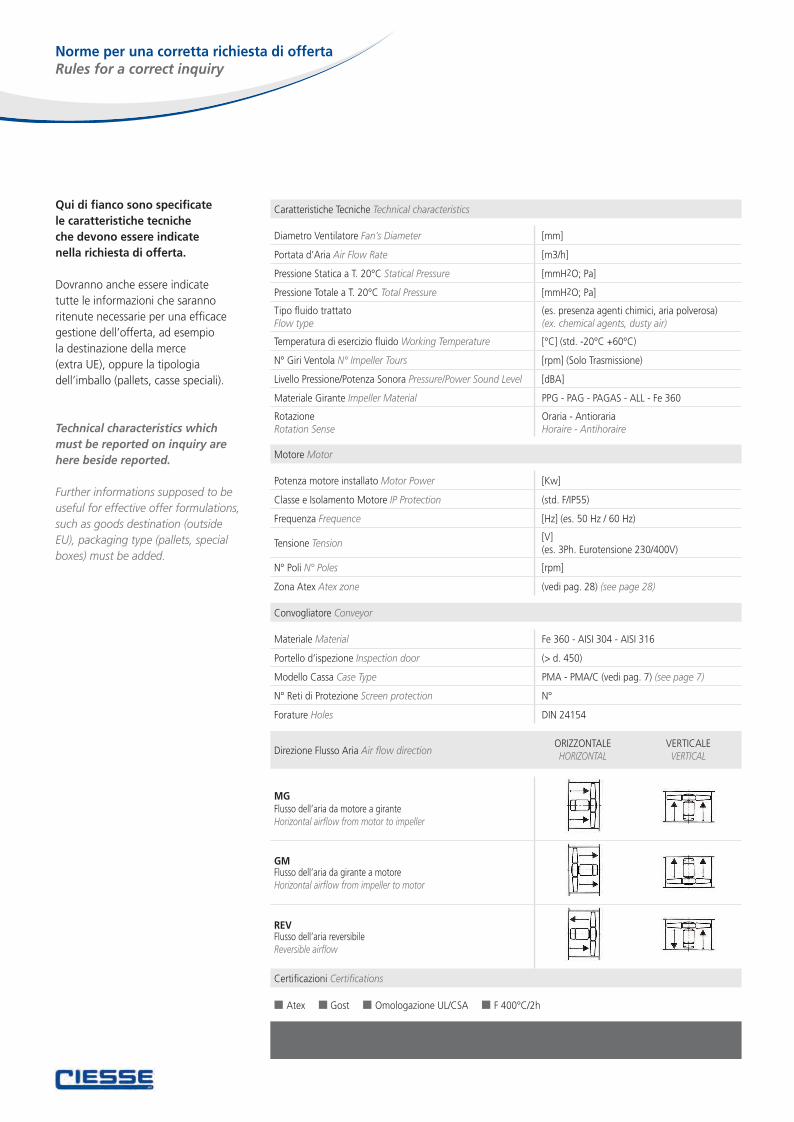
Direzione Flusso Aria Air flow direction
MGFlusso dell’aria da motore a girante Horizontal airflow from motor to impeller
GMFlusso dell’aria da girante a motoreHorizontal airflow from impeller to motor
REVFlusso dell’aria reversibileReversible airflow
Certificazioni Certifications
n Atex n Gost n Omologazione UL/CSA n F 400°C/2h
Norme per una corretta richiesta di offerta Rules for a correct inquiry
Qui di fianco sono specificatele caratteristiche tecniche che devono essere indicatenella richiesta di offerta.
Dovranno anche essere indicate tutte le informazioni che saranno ritenute necessarie per una efficace gestione dell’offerta, ad esempiola destinazione della merce (extra UE), oppure la tipologia dell’imballo (pallets, casse speciali).
Technical characteristics which must be reported on inquiry are here beside reported.
Further informations supposed to be useful for effective offer formulations, such as goods destination (outside EU), packaging type (pallets, special boxes) must be added.
ORIZZONTALEHORIZONTAL
VERTICALEVERTICAL
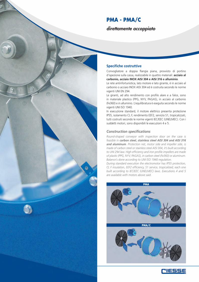
Specifiche costruttiveConvogliatore a doppia flangia piana, provvisto di portino d’ispezione sulla cassa, realizzabile in quattro materiali: acciaio al carbonio, acciaio INOX AISI 304 e AISI 316 e alluminio.Le rete antinfortunistica, lato motore e lato girante, è in acciaio al carbonio o acciaio INOX AISI 304 ed è costruita secondo le norme vigenti UNI EN 294.Le giranti, ad alto rendimento con profilo alare e a falce, sono in materiale plastico (PPG, NYV, PAGAS), in acciaio al carbonio (Fe360) e in alluminio. L’equilibratura è eseguita secondo le norme vigenti UNI ISO 1940. In esecuzione standard, il motore elettrico presenta protezione IP55, isolamento CL F, rendimento EEF2, servizio S1, tropicalizzati, tutti costruiti secondo le norme vigenti IEC/EEC (UNELMEC). Con i suddetti motori, sono disponibili le esecuzioni 4 e 5.
Construction specificationsRound-shaped conveyor with inspection door on the case is feasible in carbon steel, stainless steel AISI 304 and AISI 316 and aluminum. Protection net, motor side and impeller side, is made of carbon steel or stainless steel AISI 304, it’s built according to UNI 294 law. High efficiency and iron profile impellers are made of plastic (PPG, NYV, PAGAS), in carbon steel (Fe360) or aluminum. Balance’s done according to UNI ISO 1940 regulation.During standard execution the electromotor has IP55 protection, CL F insulation, EEF2 efficiency, S1 service, tropicalized, each one built according to IEC/EEC (UNELMEC) laws. Executions 4 and 5 are available with motors above said.
PMA - PMA/C
PMA
PMA/C
direttamente accoppiato
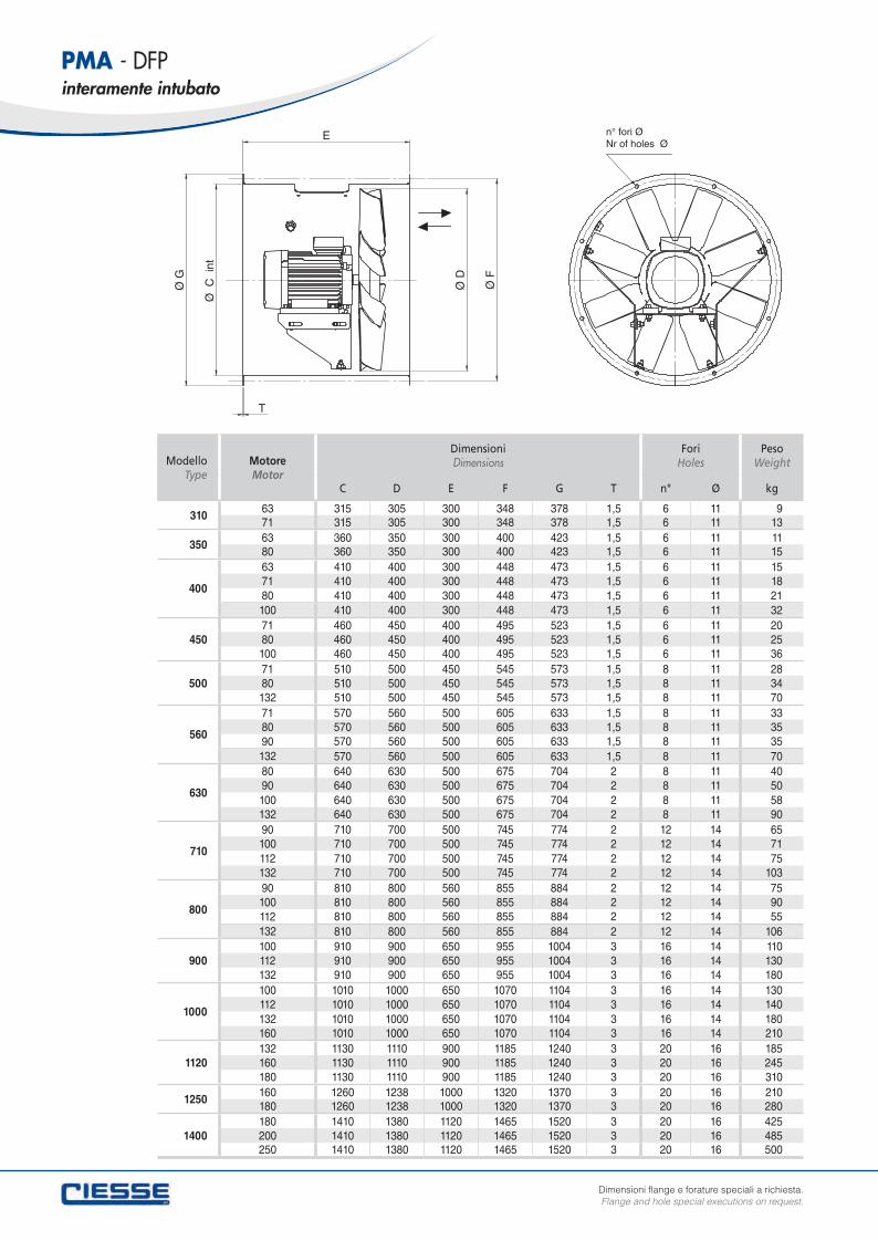
ModelloType
Motore Motor
Dimensioni Dimensions
Fori Holes
PesoWeight
C D E F G T n° Ø kg
310 63 315 305 300 348 378 1,5 6 11 971 315 305 300 348 378 1,5 6 11 13
350 63 360 350 300 400 423 1,5 6 11 1180 360 350 300 400 423 1,5 6 11 15
400
63 410 400 300 448 473 1,5 6 11 1571 410 400 300 448 473 1,5 6 11 1880 410 400 300 448 473 1,5 6 11 21100 410 400 300 448 473 1,5 6 11 32
45071 460 450 400 495 523 1,5 6 11 2080 460 450 400 495 523 1,5 6 11 25100 460 450 400 495 523 1,5 6 11 36
50071 510 500 450 545 573 1,5 8 11 2880 510 500 450 545 573 1,5 8 11 34132 510 500 450 545 573 1,5 8 11 70
560
71 570 560 500 605 633 1,5 8 11 3380 570 560 500 605 633 1,5 8 11 3590 570 560 500 605 633 1,5 8 11 35132 570 560 500 605 633 1,5 8 11 70
630
80 640 630 500 675 704 2 8 11 4090 640 630 500 675 704 2 8 11 50100 640 630 500 675 704 2 8 11 58132 640 630 500 675 704 2 8 11 90
710
90 710 700 500 745 774 2 12 14 65100 710 700 500 745 774 2 12 14 71112 710 700 500 745 774 2 12 14 75132 710 700 500 745 774 2 12 14 103
800
90 810 800 560 855 884 2 12 14 75100 810 800 560 855 884 2 12 14 90112 810 800 560 855 884 2 12 14 55132 810 800 560 855 884 2 12 14 106
900100 910 900 650 955 1004 3 16 14 110112 910 900 650 955 1004 3 16 14 130132 910 900 650 955 1004 3 16 14 180
1000
100 1010 1000 650 1070 1104 3 16 14 130112 1010 1000 650 1070 1104 3 16 14 140132 1010 1000 650 1070 1104 3 16 14 180160 1010 1000 650 1070 1104 3 16 14 210
1120132 1130 1110 900 1185 1240 3 20 16 185160 1130 1110 900 1185 1240 3 20 16 245180 1130 1110 900 1185 1240 3 20 16 310
1250 160 1260 1238 1000 1320 1370 3 20 16 210180 1260 1238 1000 1320 1370 3 20 16 280
1400180 1410 1380 1120 1465 1520 3 20 16 425200 1410 1380 1120 1465 1520 3 20 16 485250 1410 1380 1120 1465 1520 3 20 16 500
PMA - DFPinteramente intubato
Dimensioni flange e forature speciali a richiesta.Flange and hole special executions on request.
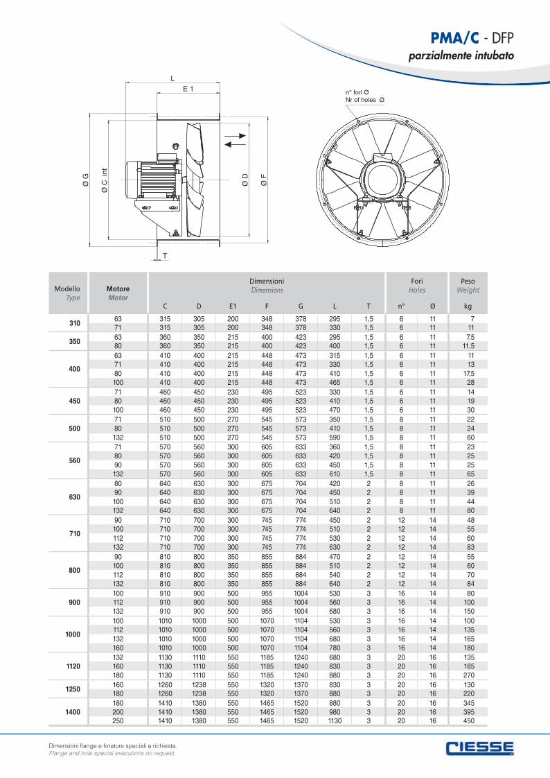
ModelloType
Motore Motor
Dimensioni Dimensions
Fori Holes
PesoWeight
C D E1 F G L T n° Ø kg
310 63 315 305 200 348 378 295 1,5 6 11 771 315 305 200 348 378 330 1,5 6 11 11
350 63 360 350 215 400 423 295 1,5 6 11 7,580 360 350 215 400 423 400 1,5 6 11 11,5
400
63 410 400 215 448 473 315 1,5 6 11 1171 410 400 215 448 473 330 1,5 6 11 1380 410 400 215 448 473 410 1,5 6 11 17,5100 410 400 215 448 473 465 1,5 6 11 28
45071 460 450 230 495 523 330 1,5 6 11 1480 460 450 230 495 523 410 1,5 6 11 19100 460 450 230 495 523 470 1,5 6 11 30
50071 510 500 270 545 573 350 1,5 8 11 2280 510 500 270 545 573 410 1,5 8 11 24132 510 500 270 545 573 590 1,5 8 11 60
560
71 570 560 300 605 633 360 1,5 8 11 2380 570 560 300 605 633 420 1,5 8 11 2590 570 560 300 605 633 450 1,5 8 11 25132 570 560 300 605 633 610 1,5 8 11 65
630
80 640 630 300 675 704 420 2 8 11 2690 640 630 300 675 704 450 2 8 11 39100 640 630 300 675 704 510 2 8 11 44132 640 630 300 675 704 640 2 8 11 80
710
90 710 700 300 745 774 450 2 12 14 48100 710 700 300 745 774 510 2 12 14 55112 710 700 300 745 774 530 2 12 14 60132 710 700 300 745 774 630 2 12 14 83
800
90 810 800 350 855 884 470 2 12 14 55100 810 800 350 855 884 510 2 12 14 60112 810 800 350 855 884 540 2 12 14 70132 810 800 350 855 884 640 2 12 14 84
900100 910 900 500 955 1004 530 3 16 14 80112 910 900 500 955 1004 560 3 16 14 100132 910 900 500 955 1004 680 3 16 14 150
1000
100 1010 1000 500 1070 1104 530 3 16 14 100112 1010 1000 500 1070 1104 560 3 16 14 135132 1010 1000 500 1070 1104 680 3 16 14 165160 1010 1000 500 1070 1104 780 3 16 14 180
1120132 1130 1110 550 1185 1240 680 3 20 16 135160 1130 1110 550 1185 1240 830 3 20 16 185180 1130 1110 550 1185 1240 880 3 20 16 270
1250 160 1260 1238 550 1320 1370 830 3 20 16 130180 1260 1238 550 1320 1370 880 3 20 16 220
1400180 1410 1380 550 1465 1520 880 3 20 16 345200 1410 1380 550 1465 1520 980 3 20 16 395250 1410 1380 550 1465 1520 1130 3 20 16 450
PMA/C - DFPparzialmente intubato
Dimensioni flange e forature speciali a richiesta.Flange and hole special executions on request.
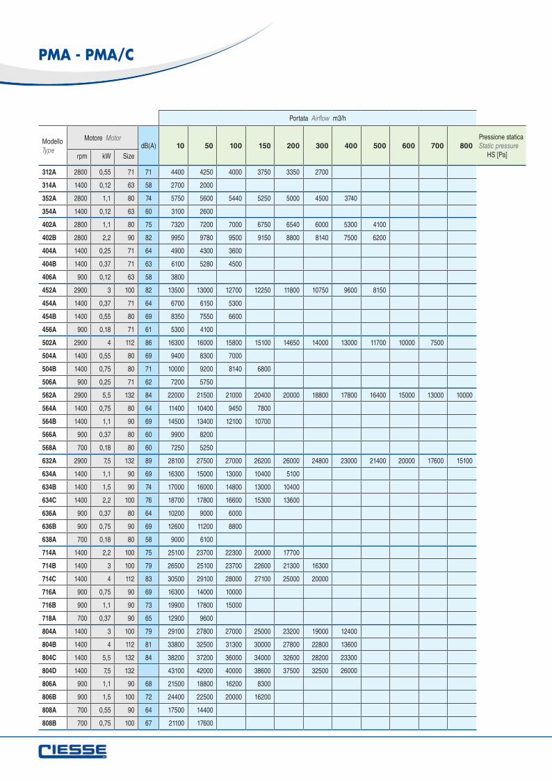
Portata Airflow m3/h
ModelloType
Motore MotordB(A) 10 50 100 150 200 300 400 500 600 700 800
rpm kW Size
312A 2800 0,55 71 71 4400 4250 4000 3750 3350 2700
314A 1400 0,12 63 58 2700 2000
352A 2800 1,1 80 74 5750 5600 5440 5250 5000 4500 3740
354A 1400 0,12 63 60 3100 2600
402A 2800 1,1 80 75 7320 7200 7000 6750 6540 6000 5300 4100
402B 2800 2,2 90 82 9950 9780 9500 9150 8800 8140 7500 6200
404A 1400 0,25 71 64 4900 4300 3600
404B 1400 0,37 71 63 6100 5280 4500
406A 900 0,12 63 58 3800
452A 2900 3 100 82 13500 13000 12700 12250 11800 10750 9600 8150
454A 1400 0,37 71 64 6700 6150 5300
454B 1400 0,55 80 69 8350 7550 6600
456A 900 0,18 71 61 5300 4100
502A 2900 4 112 86 16300 16000 15800 15100 14650 14000 13000 11700 10000 7500
504A 1400 0,55 80 69 9400 8300 7000
504B 1400 0,75 80 71 10000 9200 8140 6800
506A 900 0,25 71 62 7200 5750
562A 2900 5,5 132 84 22000 21500 21000 20400 20000 18800 17800 16400 15000 13000 10000
564A 1400 0,75 80 64 11400 10400 9450 7800
564B 1400 1,1 90 69 14500 13400 12100 10700
566A 900 0,37 80 60 9900 8200
568A 700 0,18 80 60 7250 5250
632A 2900 7,5 132 89 28100 27500 27000 26200 26000 24800 23000 21400 20000 17600 15100
634A 1400 1,1 90 69 16300 15000 13000 10400 5100
634B 1400 1,5 90 74 17000 16000 14800 13000 10400
634C 1400 2,2 100 76 18700 17800 16600 15300 13600
636A 900 0,37 80 64 10200 9000 6000
636B 900 0,75 90 69 12600 11200 8800
638A 700 0,18 80 58 9000 6100
714A 1400 2,2 100 75 25100 23700 22300 20000 17700
714B 1400 3 100 79 26500 25100 23700 22600 21300 16300
714C 1400 4 112 83 30500 29100 28000 27100 25000 20000
716A 900 0,75 90 69 16300 14000 10000
716B 900 1,1 90 73 19900 17800 15000
718A 700 0,37 90 65 12900 9600
804A 1400 3 100 79 29100 27800 27000 25000 23200 19000 12400
804B 1400 4 112 81 33800 32500 31300 30000 27800 22800 13600
804C 1400 5,5 132 84 38200 37200 36000 34000 32600 28200 23300
804D 1400 7,5 132 43100 42000 40000 38600 37500 32500 26000
806A 900 1,1 90 68 21500 18800 16200 8300
806B 900 1,5 100 72 24400 22500 20000 16200
808A 700 0,55 90 64 17500 14400
808B 700 0,75 100 67 21100 17600
Pressione statica Static pressure HS [Pa]
PMA - PMA/C
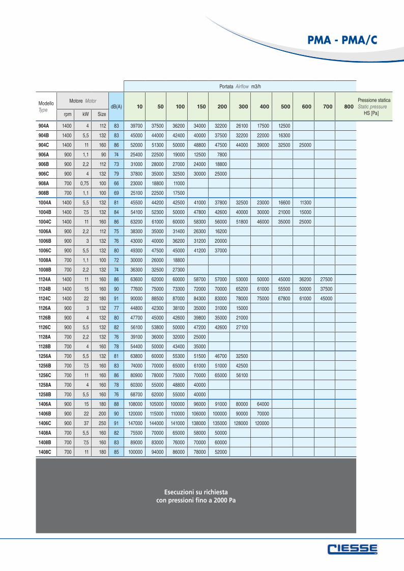
Portata Airflow m3/h
ModelloType
Motore MotordB(A) 10 50 100 150 200 300 400 500 600 700 800
rpm kW Size
904A 1400 4 112 83 39700 37500 36200 34000 32200 26100 17500 12500
904B 1400 5,5 132 83 45000 44000 42400 40000 37500 32200 22000 16300
904C 1400 11 160 86 52000 51300 50000 48800 47500 44000 39000 32500 25000
906A 900 1,1 90 74 25400 22500 19000 12500 7800
906B 900 2,2 112 73 31000 28000 27000 24000 18800
906C 900 4 132 79 37800 35000 32500 30000 25000
908A 700 0,75 100 66 23000 18800 11000
908B 700 1,1 100 69 25100 22500 17500
1004A 1400 5,5 132 81 45500 44200 42500 41000 37800 32500 23000 16600 11300
1004B 1400 7,5 132 84 54100 52300 50000 47800 42600 40000 30000 21000 15000
1004C 1400 11 160 86 63200 61000 60000 58300 56000 51800 46000 35000 25000
1006A 900 2,2 112 75 38300 35000 31400 26300 16200
1006B 900 3 132 76 43000 40000 36200 31200 20000
1006C 900 5,5 132 80 49300 47500 45000 41200 37000
1008A 700 1,1 100 72 30000 26000 18800
1008B 700 2,2 132 74 36300 32500 27300
1124A 1400 11 160 86 63600 62000 60000 58700 57000 53000 50000 45000 36200 27500
1124B 1400 15 160 90 77600 75000 73300 72000 70000 65200 61000 55500 50000 37500
1124C 1400 22 180 91 90000 88500 87000 84300 83000 78000 75000 67800 61000 45000
1126A 900 3 132 77 44800 42300 38100 35000 31000 15000
1126B 900 4 132 80 47700 45000 42600 39800 35000 21000
1126C 900 5,5 132 82 56100 53800 50000 47200 42600 27100
1128A 700 2,2 132 76 39100 36000 32000 25000
1128B 700 4 160 78 54400 50000 43400 35000
1256A 700 5,5 132 81 63800 60000 55300 51500 46700 32500
1256B 700 7,5 160 83 74000 70000 65000 61000 51000 42500
1256C 700 11 160 86 80900 78000 75000 70000 65000 56100
1258A 700 4 160 78 60300 55000 48800 40000
1258B 700 5,5 160 76 68700 62000 55000 40000
1406A 900 15 180 88 108000 105000 100000 96000 91000 80000 64000
1406B 900 22 200 90 120000 115000 110000 106000 100000 90000 70000
1406C 900 37 250 91 147000 144000 141000 138000 135000 128000 120000
1408A 700 5,5 160 82 75500 70000 65000 58000 50000
1408B 700 7,5 160 83 89000 83000 76000 70000 60000
1408C 700 11 180 85 100000 94000 86000 78000 52000
Pressione statica Static pressure HS [Pa]
PMA - PMA/C
Esecuzioni su richiestacon pressioni fino a 2000 Pa
1200
1000
800
600
400
200
0000 20000 40000 60000 80000 100000 120000
30
20
10
00PaPressione statica Static pressure
kWPotenzaassorbita Absorbedpower
m3/h Portata aria Airflow
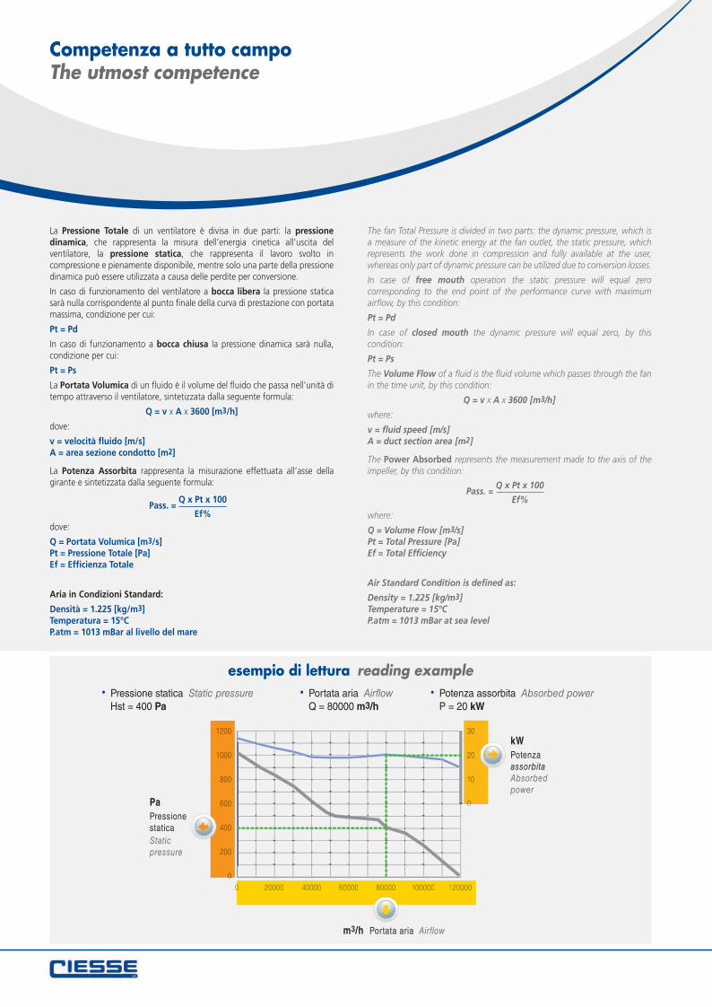
esempio di lettura reading example Portata aria Airflow
Q = 80000 m3/h Pressione statica Static pressure
Hst = 400 Pa Potenza assorbita Absorbed power
P = 20 kW
Competenza a tutto campoThe utmost competence
La Pressione Totale di un ventilatore è divisa in due parti: la pressione dinamica, che rappresenta la misura dell’energia cinetica all’uscita del ventilatore, la pressione statica, che rappresenta il lavoro svolto in compressione e pienamente disponibile, mentre solo una parte della pressione dinamica può essere utilizzata a causa delle perdite per conversione.
In caso di funzionamento del ventilatore a bocca libera la pressione statica sarà nulla corrispondente al punto finale della curva di prestazione con portata massima, condizione per cui:
Pt = Pd
In caso di funzionamento a bocca chiusa la pressione dinamica sarà nulla, condizione per cui:
Pt = Ps
La Portata Volumica di un fluido è il volume del fluido che passa nell’unità di tempo attraverso il ventilatore, sintetizzata dalla seguente formula:
Q = v x A x 3600 [m3/h]
dove:
v = velocità fluido [m/s]A = area sezione condotto [m2]
La Potenza Assorbita rappresenta la misurazione effettuata all’asse della girante e sintetizzata dalla seguente formula:
dove:
Q = Portata Volumica [m3/s]Pt = Pressione Totale [Pa] Ef = Efficienza Totale
Aria in Condizioni Standard:
Densità = 1.225 [kg/m3]Temperatura = 15°CP.atm = 1013 mBar al livello del mare
The fan Total Pressure is divided in two parts: the dynamic pressure, which is a measure of the kinetic energy at the fan outlet, the static pressure, which represents the work done in compression and fully available at the user, whereas only part of dynamic pressure can be utilized due to conversion losses.
In case of free mouth operation the static pressure will equal zero corresponding to the end point of the performance curve with maximum airflow, by this condition:
Pt = Pd
In case of closed mouth the dynamic pressure will equal zero, by this condition:
Pt = Ps
The Volume Flow of a fluid is the fluid volume which passes through the fan in the time unit, by this condition:
Q = v x A x 3600 [m3/h]
where:
v = fluid speed [m/s]A = duct section area [m2]
The Power Absorbed represents the measurement made to the axis of the impeller, by this condition:
where:
Q = Volume Flow [m3/s]Pt = Total Pressure [Pa] Ef = Total Efficiency
Air Standard Condition is defined as:
Density = 1.225 [kg/m3]Temperature = 15°CP.atm = 1013 mBar at sea level
Pass. = Q x Pt x 100
Ef%
Pass. = Q x Pt x 100
Ef%
pol
es p
oli
2
PMA
- P
MA
/C
1000
900
800
700
600
500
400
300
200
100
00 2000 4000 6000 8000 10000 12000
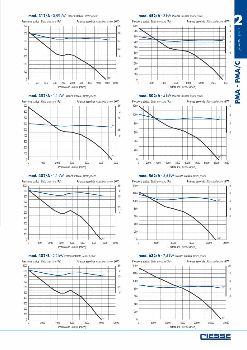
mod. 402/B 2,2 kW Potenza intallata Motor power
Pressione statica Static pressure (Pa) Potenza assorbita Absorbed power (kW)
Portata aria Airflow (m3/h)
2,5
2
1,5
1
0,5
0
40°
40°
700
600
500
400
300
200
100
00 500 1000 1500 2000 2500 3000 3500 4000 4500 5000
mod. 312/A 0,55 kW Potenza intallata Motor power
Pressione statica Static pressure (Pa) Potenza assorbita Absorbed power (kW)
Portata aria Airflow (m3/h)
0.8
0.6
0.4
0.2
0
40°
40°
900
800
700
600
500
400
300
200
100
00 1000 2000 3000 4000 5000 6000
mod. 352/A 1,1 kW Potenza intallata Motor power
Pressione statica Static pressure (Pa) Potenza assorbita Absorbed power (kW)
Portata aria Airflow (m3/h)
2,5
2
1,5
1
0,5
0
35°
35°
1000
900
800
700
600
500
400
300
200
100
00 1000 2000 3000 4000 5000 6000 7000 8000
mod. 402/A 1,1 kW Potenza intallata Motor power
Pressione statica Static pressure (Pa) Potenza assorbita Absorbed power (kW)
Portata aria Airflow (m3/h)
2,5
2
1,5
1
0,5
0
40°
40°
1000
900
800
700
600
500
400
300
200
100
00 2000 4000 6000 8000 10000 12000 14000
mod. 452/A 3 kW Potenza intallata Motor power
Pressione statica Static pressure (Pa) Potenza assorbita Absorbed power (kW)
Portata aria Airflow (m3/h)
5
4
3
2
1
0
40°
40°
1200
1000
800
600
400
200
00 2000 4000 6000 8000 10000 12000 14000 16000 18000
mod. 502/A 4 kW Potenza intallata Motor power
Pressione statica Static pressure (Pa) Potenza assorbita Absorbed power (kW)
Portata aria Airflow (m3/h)
6
2
4
0
35°
35°
1400
1200
1000
800
600
400
200
00 5000 10000 15000 20000 25000
mod. 562/A 5,5 kW Potenza intallata Motor power
Pressione statica Static pressure (Pa) Potenza assorbita Absorbed power (kW)
Portata aria Airflow (m3/h)
8
6
4
2
0
35°
35°
1400
1200
1000
800
600
400
200
00 5000 10000 15000 20000 25000 30000
mod. 632/A 7,5 kW Potenza intallata Motor power
Pressione statica Static pressure (Pa) Potenza assorbita Absorbed power (kW)
Portata aria Airflow (m3/h)
20
15
10
5
0
35°
35°
pol
es p
oli
4PM
A -
PM
A/C
160
140
120
100
80
60
40
20
00 500 1000 1500 2000 2500 3000
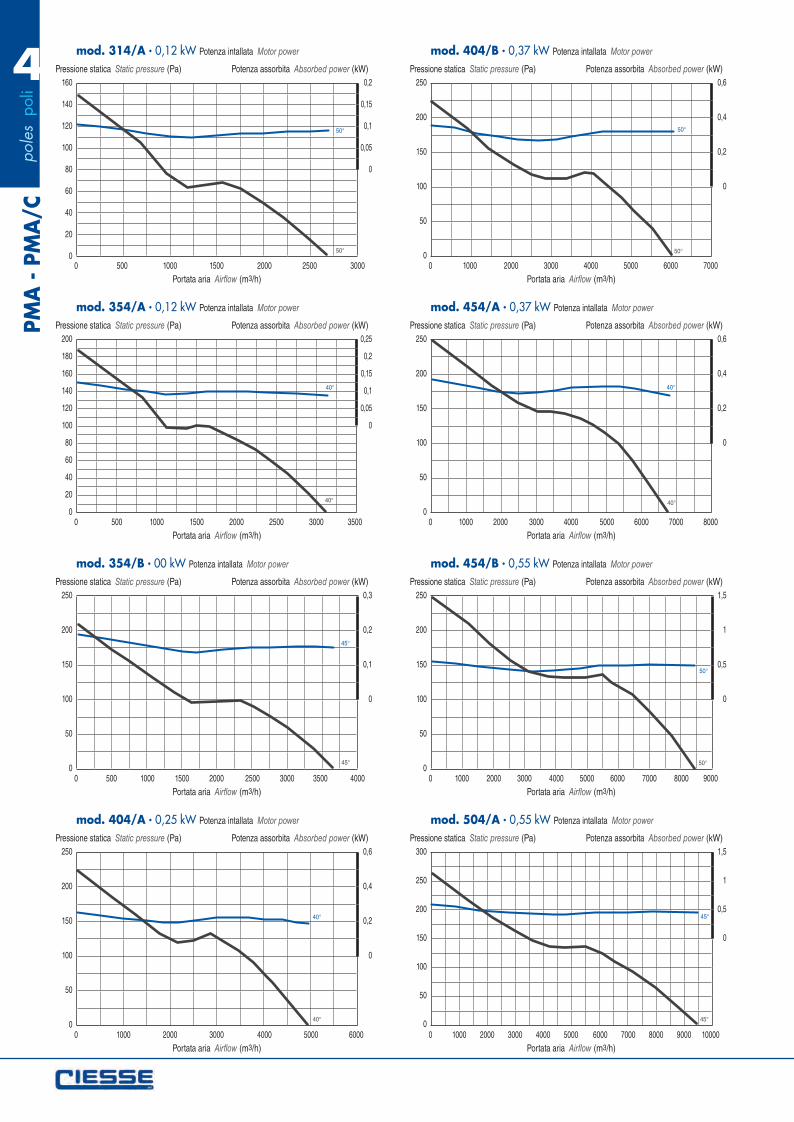
mod. 314/A 0,12 kW Potenza intallata Motor power
Pressione statica Static pressure (Pa) Potenza assorbita Absorbed power (kW)
Portata aria Airflow (m3/h)
0,2
0,15
0,1
0,05
0
50°
50°
200
180
160
140
120
100
80
60
40
20
00 500 1000 1500 2000 2500 3000 3500
mod. 354/A 0,12 kW Potenza intallata Motor power
Pressione statica Static pressure (Pa) Potenza assorbita Absorbed power (kW)
Portata aria Airflow (m3/h)
0,25
0,2
0,15
0,1
0,05
0
40°
40°
250
200
150
100
50
00 500 1000 1500 2000 2500 3000 3500 4000
mod. 354/B 00 kW Potenza intallata Motor power
Pressione statica Static pressure (Pa) Potenza assorbita Absorbed power (kW)
Portata aria Airflow (m3/h)
0,3
0,2
0,1
0
45°
45°
250
200
150
100
50
00 1000 2000 3000 4000 5000 6000
mod. 404/A 0,25 kW Potenza intallata Motor power
Pressione statica Static pressure (Pa) Potenza assorbita Absorbed power (kW)
Portata aria Airflow (m3/h)
0,6
0,4
0,2
0
40°
40°
250
200
150
100
50
00 1000 2000 3000 4000 5000 6000 7000
mod. 404/B 0,37 kW Potenza intallata Motor power
Pressione statica Static pressure (Pa) Potenza assorbita Absorbed power (kW)
Portata aria Airflow (m3/h)
0,6
0,4
0,2
0
50°
50°
250
200
150
100
50
00 1000 2000 3000 4000 5000 6000 7000 8000
mod. 454/A 0,37 kW Potenza intallata Motor power
Pressione statica Static pressure (Pa) Potenza assorbita Absorbed power (kW)
Portata aria Airflow (m3/h)
0,6
0,4
0,2
0
40°
40°
250
200
150
100
50
00 1000 2000 3000 4000 5000 6000 7000 8000 9000
mod. 454/B 0,55 kW Potenza intallata Motor power
Pressione statica Static pressure (Pa) Potenza assorbita Absorbed power (kW)
Portata aria Airflow (m3/h)
1,5
1
0,5
0
50°
50°
300
250
200
150
100
50
00 1000 2000 3000 4000 5000 6000 7000 8000 9000 10000
mod. 504/A 0,55 kW Potenza intallata Motor power
Pressione statica Static pressure (Pa) Potenza assorbita Absorbed power (kW)
Portata aria Airflow (m3/h)
1,5
1
0,5
0
45°
45°
pol
es p
oli
4
PMA
- P
MA
/C
300
250
200
150
100
50
00 2000 4000 6000 8000 10000 12000
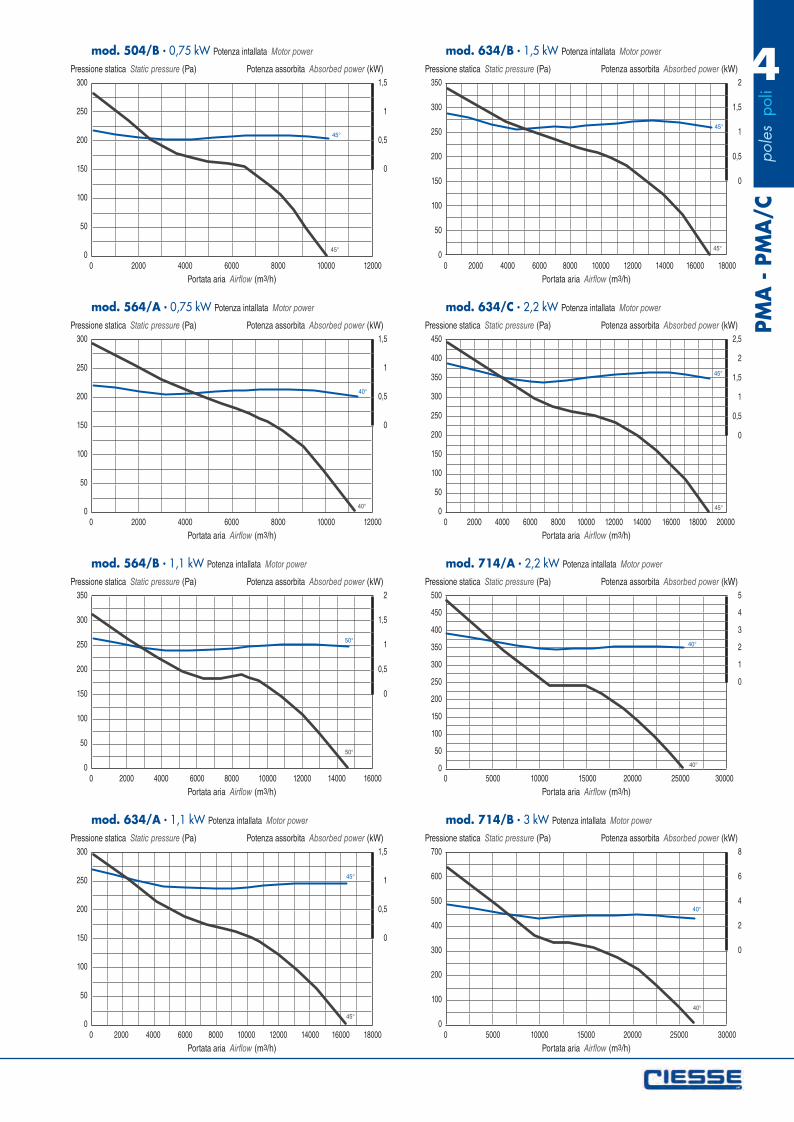
mod. 504/B 0,75 kW Potenza intallata Motor power
Pressione statica Static pressure (Pa) Potenza assorbita Absorbed power (kW)
Portata aria Airflow (m3/h)
1,5
1
0,5
0
45°
45°
300
250
200
150
100
50
00 2000 4000 6000 8000 10000 12000
mod. 564/A 0,75 kW Potenza intallata Motor power
Pressione statica Static pressure (Pa) Potenza assorbita Absorbed power (kW)
Portata aria Airflow (m3/h)
1,5
1
0,5
0
40°
40°
350
300
250
200
150
100
50
00 2000 4000 6000 8000 10000 12000 14000 16000
mod. 564/B 1,1 kW Potenza intallata Motor power
Pressione statica Static pressure (Pa) Potenza assorbita Absorbed power (kW)
Portata aria Airflow (m3/h)
2
1,5
1
0,5
0
50°
50°
300
250
200
150
100
50
00 2000 4000 6000 8000 10000 12000 14000 16000 18000
mod. 634/A 1,1 kW Potenza intallata Motor power
Pressione statica Static pressure (Pa) Potenza assorbita Absorbed power (kW)
Portata aria Airflow (m3/h)
1,5
1
0,5
0
45°
45°
350
300
250
200
150
100
50
00 2000 4000 6000 8000 10000 12000 14000 16000 18000
mod. 634/B 1,5 kW Potenza intallata Motor power
Pressione statica Static pressure (Pa) Potenza assorbita Absorbed power (kW)
Portata aria Airflow (m3/h)
2
1,5
1
0,5
0
45°
45°
450
400
350
300
250
200
150
100
50
00 2000 4000 6000 8000 10000 12000 14000 16000 18000 20000
mod. 634/C 2,2 kW Potenza intallata Motor power
Pressione statica Static pressure (Pa) Potenza assorbita Absorbed power (kW)
Portata aria Airflow (m3/h)
2,5
2
1,5
1
0,5
0
45°
45°
500
450
400
350
300
250
200
150
100
50
00 5000 10000 15000 20000 25000 30000
mod. 714/A 2,2 kW Potenza intallata Motor power
Pressione statica Static pressure (Pa) Potenza assorbita Absorbed power (kW)
Portata aria Airflow (m3/h)
5
4
3
2
1
0
40°
40°
700
600
500
400
300
200
100
00 5000 10000 15000 20000 25000 30000
mod. 714/B 3 kW Potenza intallata Motor power
Pressione statica Static pressure (Pa) Potenza assorbita Absorbed power (kW)
Portata aria Airflow (m3/h)
8
6
4
2
0
40°
40°
pol
es p
oli
4PM
A -
PM
A/C
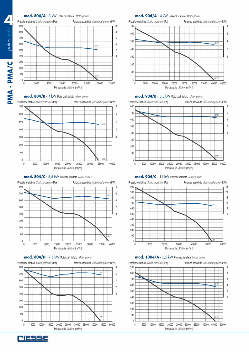
900
800
700
600
500
400
300
200
100
00 5000 1000 15000 20000 25000 30000 35000
mod. 804/A 3 kW Potenza intallata Motor power
Pressione statica Static pressure (Pa) Potenza assorbita Absorbed power (kW)
Portata aria Airflow (m3/h)
10
8
6
4
2
0
32,5°
32,5°
700
600
500
400
300
200
100
00 5000 10000 15000 20000 25000 30000 35000 40000
mod. 804/B 4 kW Potenza intallata Motor power
Pressione statica Static pressure (Pa) Potenza assorbita Absorbed power (kW)
Portata aria Airflow (m3/h)
8
6
4
2
0
37,5°
37.5°
800
700
600
500
400
300
200
100
00 5000 10000 15000 20000 25000 30000 35000 40000
mod. 804/C 5,5 kW Potenza intallata Motor power
Pressione statica Static pressure (Pa) Potenza assorbita Absorbed power (kW)
Portata aria Airflow (m3/h)
8
6
4
2
0
40°
40°
800
700
600
500
400
300
200
100
00 5000 10000 15000 20000 25000 30000 35000 40000 45000 50000
mod. 804/D 7,5 kW Potenza intallata Motor power
Pressione statica Static pressure (Pa) Potenza assorbita Absorbed power (kW)
Portata aria Airflow (m3/h)
8
6
4
2
0
45°
45°
700
600
500
400
300
200
100
00 5000 10000 15000 20000 25000 30000 35000 40000 45000
mod. 904/A 4 kW Potenza intallata Motor power
Pressione statica Static pressure (Pa) Potenza assorbita Absorbed power (kW)
Portata aria Airflow (m3/h)
8
6
4
2
0
32,5°
32.5°
800
700
600
500
400
300
200
100
00 5000 10000 15000 20000 25000 30000 35000 40000 45000 50000
mod. 904/B 5,5 kW Potenza intallata Motor power
Pressione statica Static pressure (Pa) Potenza assorbita Absorbed power (kW)
Portata aria Airflow (m3/h)
8
6
4
2
0
37,5°
37,5°
1000
900
800
700
600
500
400
300
200
100
00 10000 20000 30000 40000 50000 60000
mod. 904/C 11 kW Potenza intallata Motor power
Pressione statica Static pressure (Pa) Potenza assorbita Absorbed power (kW)
Portata aria Airflow (m3/h)
52
20
15
10
5
0
40°
40°
900
800
700
600
500
400
300
200
100
00 5000 10000 15000 20000 25000 30000 35000 40000 45000 50000
mod. 1004/A 5,5 kW Potenza intallata Motor power
Pressione statica Static pressure (Pa) Potenza assorbita Absorbed power (kW)
Portata aria Airflow (m3/h)
10
8
6
4
2
0
32,5°
32,5°
pol
es p
oli
4
PMA
- P
MA
/C
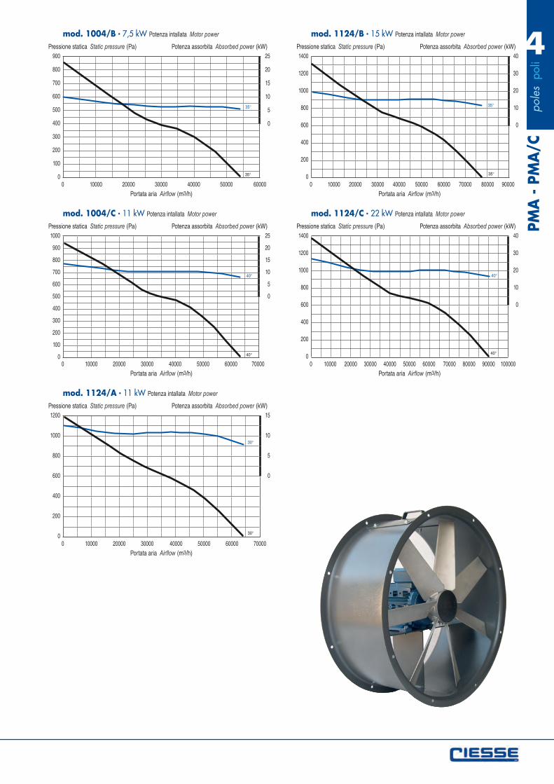
900
800
700
600
500
400
300
200
100
00 10000 20000 30000 40000 50000 60000
mod. 1004/B 7,5 kW Potenza intallata Motor power
Pressione statica Static pressure (Pa) Potenza assorbita Absorbed power (kW)
Portata aria Airflow (m3/h)
25
20
15
10
5
0
35°
35°
1000
900
800
700
600
500
400
300
200
100
00 10000 20000 30000 40000 50000 60000 70000
mod. 1004/C 11 kW Potenza intallata Motor power
Pressione statica Static pressure (Pa) Potenza assorbita Absorbed power (kW)
Portata aria Airflow (m3/h)
25
20
15
10
5
0
40°
40°
1200
1000
800
600
400
200
00 10000 20000 30000 40000 50000 60000 70000
mod. 1124/A 11 kW Potenza intallata Motor power
Pressione statica Static pressure (Pa) Potenza assorbita Absorbed power (kW)
Portata aria Airflow (m3/h)
15
10
5
0
30°
30°
1400
1200
1000
800
600
400
200
00 10000 20000 30000 40000 50000 60000 70000 80000 90000
mod. 1124/B 15 kW Potenza intallata Motor power
Pressione statica Static pressure (Pa) Potenza assorbita Absorbed power (kW)
Portata aria Airflow (m3/h)
40
30
20
10
0
35°
35°
1400
1200
1000
800
600
400
200
00 10000 20000 30000 40000 50000 60000 70000 80000 90000 100000
mod. 1124/C 22 kW Potenza intallata Motor power
Pressione statica Static pressure (Pa) Potenza assorbita Absorbed power (kW)
Portata aria Airflow (m3/h)
40
30
20
10
0
40°
40°
correzioni_Layout 1 17/05/12 14.52 Pagina 1
pol
es p
oli
6PM
A -
PM
A/C
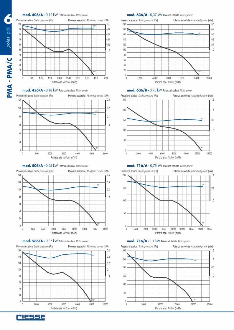
100
90
80
70
60
50
40
30
20
10
0 500 1000 1500 2000 2500 3000 3500 4000 4500
mod. 406/A 0,12 kW Potenza intallata Motor power
Pressione statica Static pressure (Pa) Potenza assorbita Absorbed power (kW)
Portata aria Airflow (m3/h)
0,1
0,08
0,06
0,04
0,02
0
50°
50°
120
100
80
60
40
20
00 1000 2000 3000 4000 5000 6000
mod. 456/A 0,18 kW Potenza intallata Motor power
Pressione statica Static pressure (Pa) Potenza assorbita Absorbed power (kW)
Portata aria Airflow (m3/h)
0,3
0,2
0,1
0
45°
45°
140
120
100
80
60
40
20
00 1000 2000 3000 4000 5000 6000 7000 8000
mod. 506/A 0,25 kW Potenza intallata Motor power
Pressione statica Static pressure (Pa) Potenza assorbita Absorbed power (kW)
Portata aria Airflow (m3/h)
0,4
0,3
0,2
0
50°
50°
160
140
120
100
80
60
40
20
00 2000 4000 6000 8000 10000 12000
mod. 566/A 0,37 kW Potenza intallata Motor power
Pressione statica Static pressure (Pa) Potenza assorbita Absorbed power (kW)
Portata aria Airflow (m3/h)
0,4
0,3
0,2
0,1
0
50°
50°
200
180
160
140
120
100
80
60
40
20
00 2000 4000 6000 8000 10000 12000
mod. 636/A 0,37 kW Potenza intallata Motor power
Pressione statica Static pressure (Pa) Potenza assorbita Absorbed power (kW)
Portata aria Airflow (m3/h)
0,5
0,4
0,3
0,2
0,1
0
40°
40°
250
200
150
100
50
00 2000 4000 6000 8000 10000 12000 14000
mod. 636/B 0,75 kW Potenza intallata Motor power
Pressione statica Static pressure (Pa) Potenza assorbita Absorbed power (kW)
Portata aria Airflow (m3/h)
1,5
1
0,5
0
45°
45°
200
150
100
50
00 2000 4000 6000 8000 10000 12000 14000 16000 18000
mod. 716/A 0,75 kW Potenza intallata Motor power
Pressione statica Static pressure (Pa) Potenza assorbita Absorbed power (kW)
Portata aria Airflow (m3/h)
1
0,5
0
40°
40°
300
250
200
150
100
50
00 5000 10000 15000 20000 25000
mod. 716/B 1,1 kW Potenza intallata Motor power
Pressione statica Static pressure (Pa) Potenza assorbita Absorbed power (kW)
Portata aria Airflow (m3/h)
1,5
1
0,5
0
45°
45°
pol
es p
oli
6
PMA
- P
MA
/C
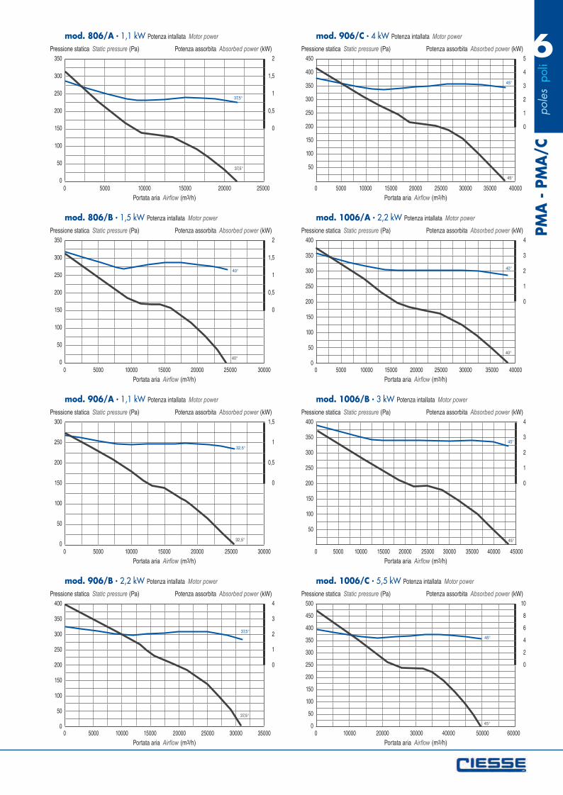
350
300
250
200
150
100
50
00 5000 10000 15000 20000 25000
mod. 806/A 1,1 kW Potenza intallata Motor power
Pressione statica Static pressure (Pa) Potenza assorbita Absorbed power (kW)
Portata aria Airflow (m3/h)
2
1,5
1
0,5
0
37,5°
37,5°
350
300
250
200
150
100
50
00 5000 10000 15000 20000 25000 30000
mod. 806/B 1,5 kW Potenza intallata Motor power
Pressione statica Static pressure (Pa) Potenza assorbita Absorbed power (kW)
Portata aria Airflow (m3/h)
2
1,5
1
0,5
0
40°
40°
300
250
200
150
100
50
00 5000 10000 15000 20000 25000 30000
mod. 906/A 1,1 kW Potenza intallata Motor power
Pressione statica Static pressure (Pa) Potenza assorbita Absorbed power (kW)
Portata aria Airflow (m3/h)
1,5
1
0,5
0
32,5°
32,5°
400
350
300
250
200
150
100
50
00 5000 10000 15000 20000 25000 30000 35000
mod. 906/B 2,2 kW Potenza intallata Motor power
Pressione statica Static pressure (Pa) Potenza assorbita Absorbed power (kW)
Portata aria Airflow (m3/h)
4
3
2
1
0
37,5°
37,5°
450
400
350
300
250
200
150
100
50
0 5000 10000 15000 20000 25000 30000 35000 40000
mod. 906/C 4 kW Potenza intallata Motor power
Pressione statica Static pressure (Pa) Potenza assorbita Absorbed power (kW)
Portata aria Airflow (m3/h)
5
4
3
2
1
0
45°
45°
400
350
300
250
200
150
100
50
00 5000 10000 15000 20000 25000 30000 35000 40000
mod. 1006/A 2,2 kW Potenza intallata Motor power
Pressione statica Static pressure (Pa) Potenza assorbita Absorbed power (kW)
Portata aria Airflow (m3/h)
4
3
2
1
0
40°
40°
400
350
300
250
200
150
100
50
0 5000 10000 15000 20000 25000 30000 35000 40000 45000
mod. 1006/B 3 kW Potenza intallata Motor power
Pressione statica Static pressure (Pa) Potenza assorbita Absorbed power (kW)
Portata aria Airflow (m3/h)
4
3
2
1
0
45°
45°
500
450
400
350
300
250
200
150
100
50
00 10000 20000 30000 40000 50000 60000
mod. 1006/C 5,5 kW Potenza intallata Motor power
Pressione statica Static pressure (Pa) Potenza assorbita Absorbed power (kW)
Portata aria Airflow (m3/h)
10
8
6
4
2
0
45°
45°
pol
es p
oli
6PM
A -
PM
A/C
500
400
300
200
100
00 5000 10000 15000 20000 25000 30000 35000 40000 45000 50000
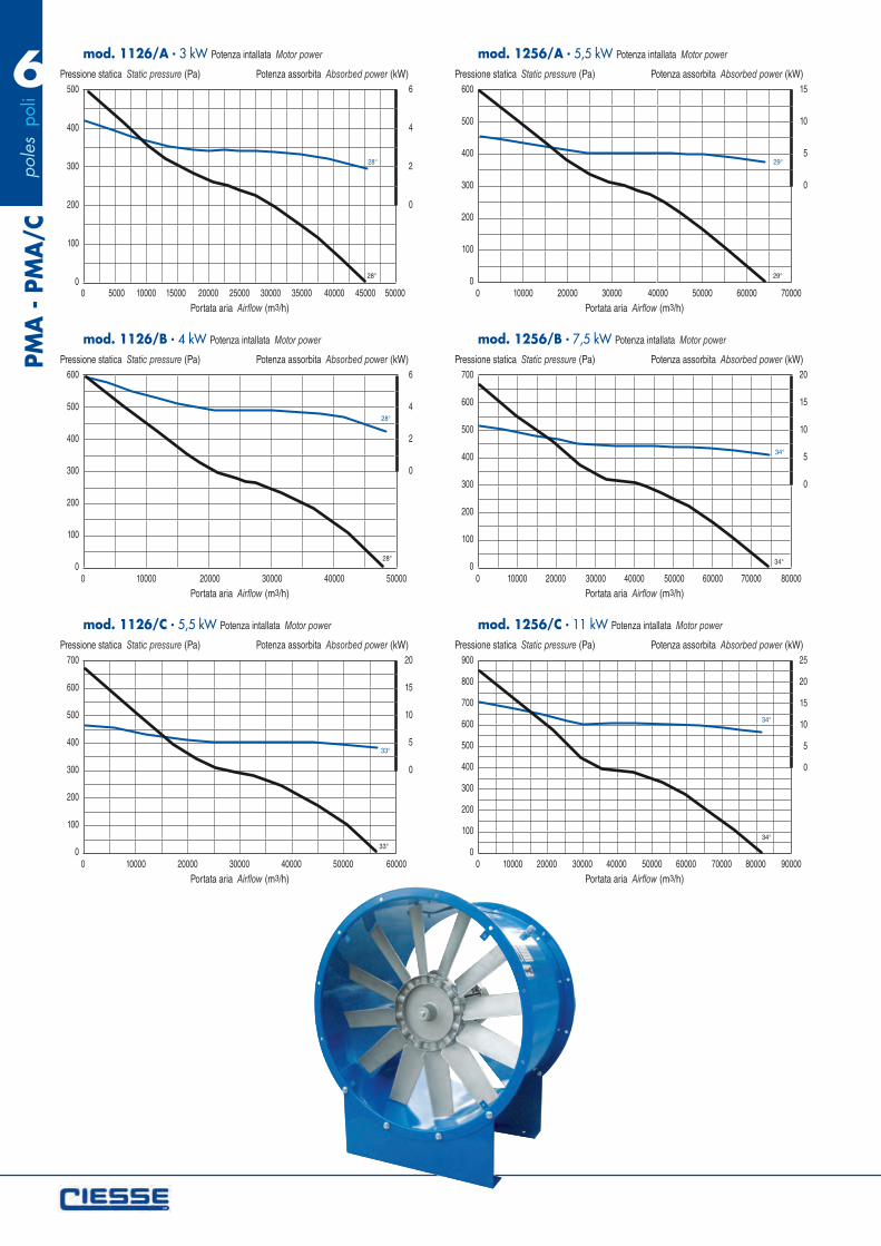
mod. 1126/A 3 kW Potenza intallata Motor power
Pressione statica Static pressure (Pa) Potenza assorbita Absorbed power (kW)
Portata aria Airflow (m3/h)
6
4
2
0
28°
28°
600
500
400
300
200
100
00 10000 20000 30000 40000 50000
mod. 1126/B 4 kW Potenza intallata Motor power
Pressione statica Static pressure (Pa) Potenza assorbita Absorbed power (kW)
Portata aria Airflow (m3/h)
6
4
2
0
28°
28°
700
600
500
400
300
200
100
00 10000 20000 30000 40000 50000 60000
mod. 1126/C 5,5 kW Potenza intallata Motor power
Pressione statica Static pressure (Pa) Potenza assorbita Absorbed power (kW)
Portata aria Airflow (m3/h)
20
15
10
5
0
33°
33°
600
500
400
300
200
100
00 10000 20000 30000 40000 50000 60000 70000
mod. 1256/A 5,5 kW Potenza intallata Motor power
Pressione statica Static pressure (Pa) Potenza assorbita Absorbed power (kW)
Portata aria Airflow (m3/h)
15
10
5
0
29°
29°
700
600
500
400
300
200
100
00 10000 20000 30000 40000 50000 60000 70000 80000
mod. 1256/B 7,5 kW Potenza intallata Motor power
Pressione statica Static pressure (Pa) Potenza assorbita Absorbed power (kW)
Portata aria Airflow (m3/h)
20
15
10
5
0
34°
34°
900
800
700
600
500
400
300
200
100
00 10000 20000 30000 40000 50000 60000 70000 80000 90000
mod. 1256/C 11 kW Potenza intallata Motor power
Pressione statica Static pressure (Pa) Potenza assorbita Absorbed power (kW)
Portata aria Airflow (m3/h)
25
20
15
10
5
0
34°
34°
correzioni_Layout 1 17/05/12 14.52 Pagina 2
pol
es p
oli
6
PMA
- P
MA
/C
900
800
700
600
500
400
300
200
100
00 20000 40000 60000 80000 100000 120000
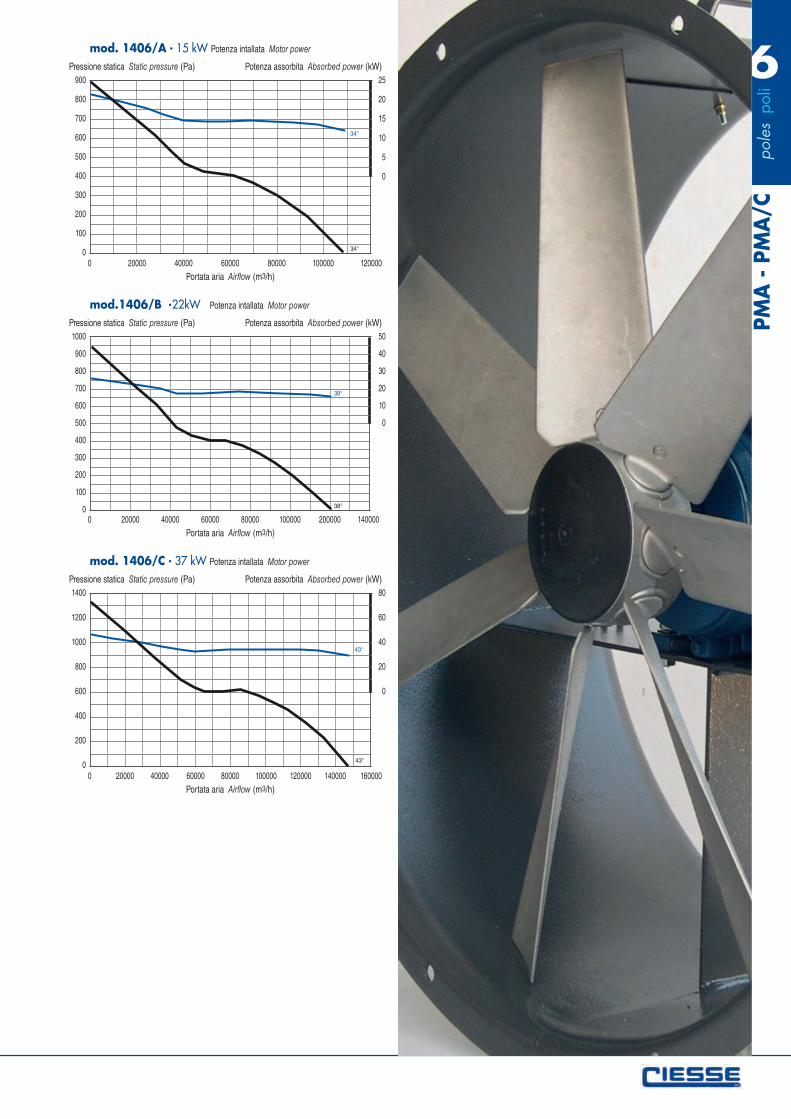
mod. 1406/A 15 kW Potenza intallata Motor power
Pressione statica Static pressure (Pa) Potenza assorbita Absorbed power (kW)
Portata aria Airflow (m3/h)
25
20
15
10
5
0
34°
34°
1000
900
800
700
600
500
400
300
200
100
00 20000 40000 60000 80000 100000 200000 140000
mod.1406/B 22kW Potenza intallata Motor power
Pressione statica Static pressure (Pa) Potenza assorbita Absorbed power (kW)
Portata aria Airflow (m3/h)
50
40
30
20
10
0
38°
38°
1400
1200
1000
800
600
400
200
00 20000 40000 60000 80000 100000 120000 140000 160000
mod. 1406/C 37 kW Potenza intallata Motor power
Pressione statica Static pressure (Pa) Potenza assorbita Absorbed power (kW)
Portata aria Airflow (m3/h)
80
60
40
20
0
43°
43°
PAGINA 21_21 17/05/12 14.57 Pagina 1

pol
es p
oli
8PM
A -
PM
A/C
120
100
80
60
40
20
00 1000 2000 3000 4000 5000 6000 7000 8000
mod. 568/A 0,18 kW Potenza intallata Motor power
Pressione statica Static pressure (Pa) Potenza assorbita Absorbed power (kW)
Portata aria Airflow (m3/h)
0,3
0,2
0,1
0
45°
45°
100
80
60
40
20
00 1000 2000 3000 4000 5000 6000 7000 8000 9000 10000
mod. 638/A 0,18 kW Potenza intallata Motor power
Pressione statica Static pressure (Pa) Potenza assorbita Absorbed power (kW)
Portata aria Airflow (m3/h)
0,3
0,2
0,1
0
45°
45°
180
160
140
120
100
80
60
40
20
00 2000 4000 6000 8000 10000 12000 14000
mod. 718/A 0,37 kW Potenza intallata Motor power
Pressione statica Static pressure (Pa) Potenza assorbita Absorbed power (kW)
Portata aria Airflow (m3/h)
1
0,8
0,6
0,4
0,2
0
40°
40°
180
160
140
120
100
80
60
40
20
00 2000 4000 6000 8000 10000 12000 14000 16000 18000 20000
mod. 808/A 0,55 kW Potenza intallata Motor power
Pressione statica Static pressure (Pa) Potenza assorbita Absorbed power (kW)
Portata aria Airflow (m3/h)
1
0,8
0,6
0,4
0,2
0
40°
40°
180
160
140
120
100
80
60
40
20
00 5000 10000 15000 20000 25000
mod. 808/B 0,75 kW Potenza intallata Motor power
Pressione statica Static pressure (Pa) Potenza assorbita Absorbed power (kW)
Portata aria Airflow (m3/h)
1
0,8
0,6
0,4
0,2
0
45°
45°
200
180
160
140
120
100
80
60
40
20
00 5000 10000 15000 20000 25000
mod. 908/A 0,75 kW Potenza intallata Motor power
Pressione statica Static pressure (Pa) Potenza assorbita Absorbed power (kW)
Portata aria Airflow (m3/h)
1
0,8
0,6
0,4
0,2
0
37,5°
37,5°
250
200
150
100
50
00 5000 10000 15000 20000 25000 30000
mod. 908/B 1,1 kW Potenza intallata Motor power
Pressione statica Static pressure (Pa) Potenza assorbita Absorbed power (kW)
Portata aria Airflow (m3/h)
1,5
1
0,5
0
40°
40°
250
200
150
100
50
00 5000 10000 15000 20000 25000 30000 35000
mod. 1008/A 1,1 kW Potenza intallata Motor power
Pressione statica Static pressure (Pa) Potenza assorbita Absorbed power (kW)
Portata aria Airflow (m3/h)
3
2
1
0
40°
40°

pol
es p
oli
8
PMA
- P
MA
/C
250
200
150
100
50
00 5000 10000 15000 20000 25000 30000 35000 40000
mod. 1008/B 2,2 kW Potenza intallata Motor power
Pressione statica Static pressure (Pa) Potenza assorbita Absorbed power (kW)
Portata aria Airflow (m3/h)
3
2
1
0
45°
45°
400
350
300
250
200
150
100
50
0 5000 10000 15000 20000 25000 30000 35000 40000 45000
mod. 1128/A 2,2 kW Potenza intallata Motor power
Pressione statica Static pressure (Pa) Potenza assorbita Absorbed power (kW)
Portata aria Airflow (m3/h)
4
3
2
1
0
30°
30°
450
400
350
300
250
200
150
100
50
00 10000 20000 30000 40000 50000 60000
mod. 1128/B 4 kW Potenza intallata Motor power
Pressione statica Static pressure (Pa) Potenza assorbita Absorbed power (kW)
Portata aria Airflow (m3/h)
10
8
6
4
2
0
43°
43°
400
350
300
250
200
150
100
50
00 10000 20000 30000 40000 50000 60000 70000
mod. 1258/A 4 kW Potenza intallata Motor power
Pressione statica Static pressure (Pa) Potenza assorbita Absorbed power (kW)
Portata aria Airflow (m3/h)
8
6
4
2
0
37°
37°
400
350
300
250
200
150
100
50
00 10000 20000 30000 40000 50000 60000 70000 80000
mod. 1258/A 5,5 kW Potenza intallata Motor power
Pressione statica Static pressure (Pa) Potenza assorbita Absorbed power (kW)
Portata aria Airflow (m3/h)
8
6
4
2
0
44°
44°
500
450
400
350
300
250
200
150
100
50
00 10000 20000 30000 40000 50000 60000 70000 80000
mod. 1408/A 5,5 kW Potenza intallata Motor power
Pressione statica Static pressure (Pa) Potenza assorbita Absorbed power (kW)
Portata aria Airflow (m3/h)
10
8
6
4
2
0
31°
31°
600
500
400
300
200
100
00 10000 20000 30000 40000 50000 60000 70000 80000 90000 100000
mod. 1408/B 7,5 kW Potenza intallata Motor power
Pressione statica Static pressure (Pa) Potenza assorbita Absorbed power (kW)
Portata aria Airflow (m3/h)
15
10
5
0
37°
37°
600
500
400
300
200
100
00 20000 40000 60000 80000 100000 120000
mod. 1408/C 11 kW Potenza intallata Motor power
Pressione statica Static pressure (Pa) Potenza assorbita Absorbed power (kW)
Portata aria Airflow (m3/h)
15
10
5
0
44°
44°
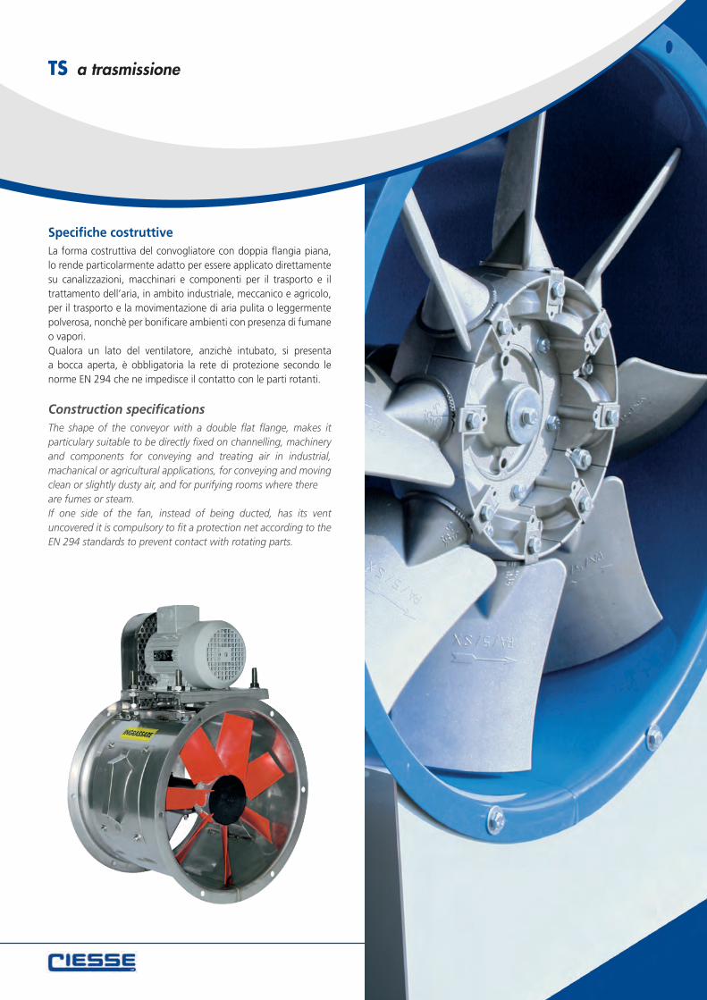
Specifiche costruttiveLa forma costruttiva del convogliatore con doppia flangia piana, lo rende particolarmente adatto per essere applicato direttamente su canalizzazioni, macchinari e componenti per il trasporto e il trattamento dell’aria, in ambito industriale, meccanico e agricolo, per il trasporto e la movimentazione di aria pulita o leggermente polverosa, nonchè per bonificare ambienti con presenza di fumane o vapori.Qualora un lato del ventilatore, anzichè intubato, si presenta a bocca aperta, è obbligatoria la rete di protezione secondo le norme EN 294 che ne impedisce il contatto con le parti rotanti.
Construction specificationsThe shape of the conveyor with a double flat flange, makes it particulary suitable to be directly fixed on channelling, machinery and components for conveying and treating air in industrial, machanical or agricultural applications, for conveying and moving clean or slightly dusty air, and for purifying rooms where thereare fumes or steam.If one side of the fan, instead of being ducted, has its vent uncovered it is compulsory to fit a protection net according to the EN 294 standards to prevent contact with rotating parts.
TS a trasmissione
correzioni_Layout 1 17/05/12 14.52 Pagina 3
TS
ModelloType
Dimensioni Dimensions
Fori Holes
PesoWeight
C D E F G T n° Ø kg
310 315 305 350 348 378 1,5 6 11 30
350 360 350 350 400 423 1,5 6 11 33
400 410 400 350 448 473 1,5 6 11 45
450 460 450 400 495 523 1,5 6 11 63
500 510 500 550 545 573 1,5 8 11 80
560 570 560 550 605 633 1,5 8 11 90
600 610 600 550 645 673 1,5 8 11 95
630 640 630 550 675 704 2 8 11 100
710 710 700 550 745 774 2 12 14 125
800 810 800 550 855 884 2 12 14 135
900 910 900 750 955 1004 3 16 14 210
1000 1010 1000 750 1070 1104 3 16 14 220
1120 1130 1110 850 1185 1240 3 20 16 280
1250 1260 1238 850 1320 1370 3 20 16 390
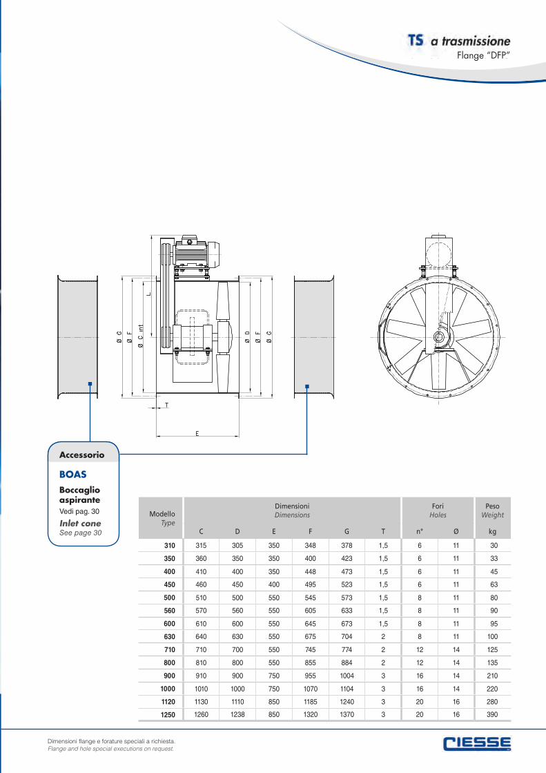
Accessorio
BOAS
Boccaglio aspiranteVedi pag. 30
Inlet coneSee page 30
a trasmissione
Dimensioni flange e forature speciali a richiesta.Flange and hole special executions on request.
Flange “DFP”
correzioni_Layout 1 17/05/12 14.52 Pagina 4
Potenza installata
Motor power
PoliPoles
Giri ventolaR.P.M.
impellerSpl dB(A)
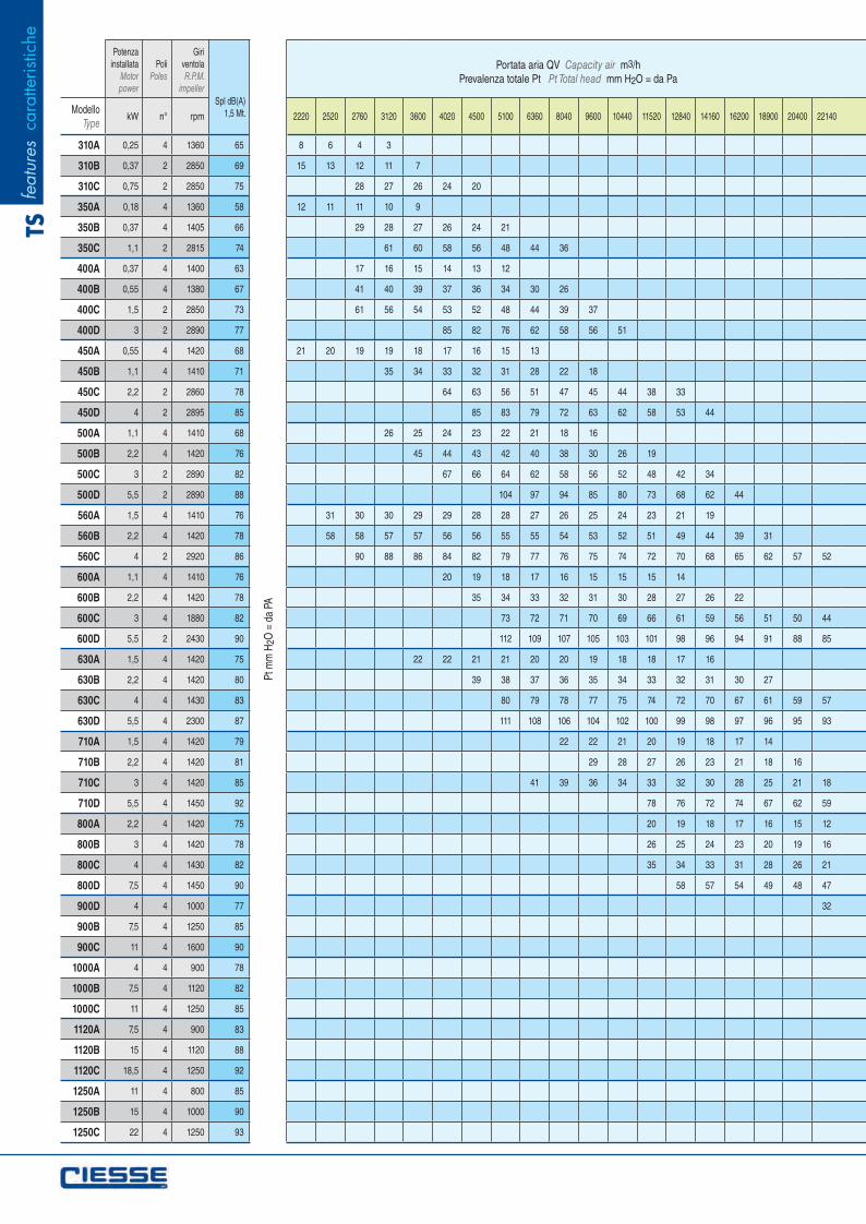
1,5 Mt.ModelloType
kW n° rpm 2220 2520 2760 3120 3600 4020 4500 5100 6360 8040 9600 10440 11520 12840 14160 16200 18900 20400 22140
310A 0,25 4 1360 65 8 6 4 3
310B 0,37 2 2850 69 15 13 12 11 7
310C 0,75 2 2850 75 28 27 26 24 20
350A 0,18 4 1360 58 12 11 11 10 9
350B 0,37 4 1405 66 29 28 27 26 24 21
350C 1,1 2 2815 74 61 60 58 56 48 44 36
400A 0,37 4 1400 63 17 16 15 14 13 12
400B 0,55 4 1380 67 41 40 39 37 36 34 30 26
400C 1,5 2 2850 73 61 56 54 53 52 48 44 39 37
400D 3 2 2890 77 85 82 76 62 58 56 51
450A 0,55 4 1420 68 21 20 19 19 18 17 16 15 13
450B 1,1 4 1410 71 35 34 33 32 31 28 22 18
450C 2,2 2 2860 78 64 63 56 51 47 45 44 38 33
450D 4 2 2895 85 85 83 79 72 63 62 58 53 44
500A 1,1 4 1410 68 26 25 24 23 22 21 18 16
500B 2,2 4 1420 76 45 44 43 42 40 38 30 26 19
500C 3 2 2890 82 67 66 64 62 58 56 52 48 42 34
500D 5,5 2 2890 88 104 97 94 85 80 73 68 62 44
560A 1,5 4 1410 76 31 30 30 29 29 28 28 27 26 25 24 23 21 19
560B 2,2 4 1420 78 58 58 57 57 56 56 55 55 54 53 52 51 49 44 39 31
560C 4 2 2920 86 90 88 86 84 82 79 77 76 75 74 72 70 68 65 62 57 52
600A 1,1 4 1410 76 20 19 18 17 16 15 15 15 14
600B 2,2 4 1420 78 35 34 33 32 31 30 28 27 26 22
600C 3 4 1880 82 73 72 71 70 69 66 61 59 56 51 50 44
600D 5,5 2 2430 90 112 109 107 105 103 101 98 96 94 91 88 85
630A 1,5 4 1420 75 22 22 21 21 20 20 19 18 18 17 16
630B 2,2 4 1420 80 39 38 37 36 35 34 33 32 31 30 27
630C 4 4 1430 83 80 79 78 77 75 74 72 70 67 61 59 57
630D 5,5 4 2300 87 111 108 106 104 102 100 99 98 97 96 95 93
710A 1,5 4 1420 79 22 22 21 20 19 18 17 14
710B 2,2 4 1420 81 29 28 27 26 23 21 18 16
710C 3 4 1420 85 41 39 36 34 33 32 30 28 25 21 18
710D 5,5 4 1450 92 78 76 72 74 67 62 59
800A 2,2 4 1420 75 20 19 18 17 16 15 12
800B 3 4 1420 78 26 25 24 23 20 19 16
800C 4 4 1430 82 35 34 33 31 28 26 21
800D 7,5 4 1450 90 58 57 54 49 48 47
900D 4 4 1000 77 32
900B 7,5 4 1250 85
900C 11 4 1600 90
1000A 4 4 900 78
1000B 7,5 4 1120 82
1000C 11 4 1250 85
1120A 7,5 4 900 83
1120B 15 4 1120 88
1120C 18,5 4 1250 92
1250A 11 4 800 85
1250B 15 4 1000 90
1250C 22 4 1250 93
Pt m
m H
2O =
da
PA
Portata aria QV Capacity air m3/hPrevalenza totale Pt Pt Total head mm H2O = da Pa
feat
ures
car
atte
ristic
heTS
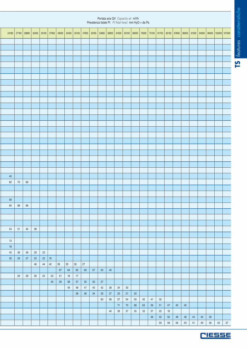
24180 27180 28860 32400 35100 37900 40000 42400 45100 47600 50100 54800 58900 61000 63100 66000 70000 75100 81700 85100 87600 89000 91200 94000 98400 102000 107000
40
82 70 66
56
90 88 86
54 51 45 38
13
18
45 39 36 29 23
30 29 27 25 22 18
46 44 42 39 35 30 27
67 64 62 60 57 50 40
29 28 26 24 23 21 18 17
40 39 38 37 35 33 27
49 48 47 45 42 38 34 30
38 36 34 30 27 25 21 20
60 58 57 54 50 45 41 32
71 70 68 63 56 51 47 45 40
40 39 37 35 33 27 22 18
56 52 50 48 46 44 40 30
59 58 56 53 51 49 46 42 37
Portata aria QV Capacity air m3/hPrevalenza totale Pt Pt Total head mm H2O = da Pa
feat
ures
car
atte
ristic
heTS
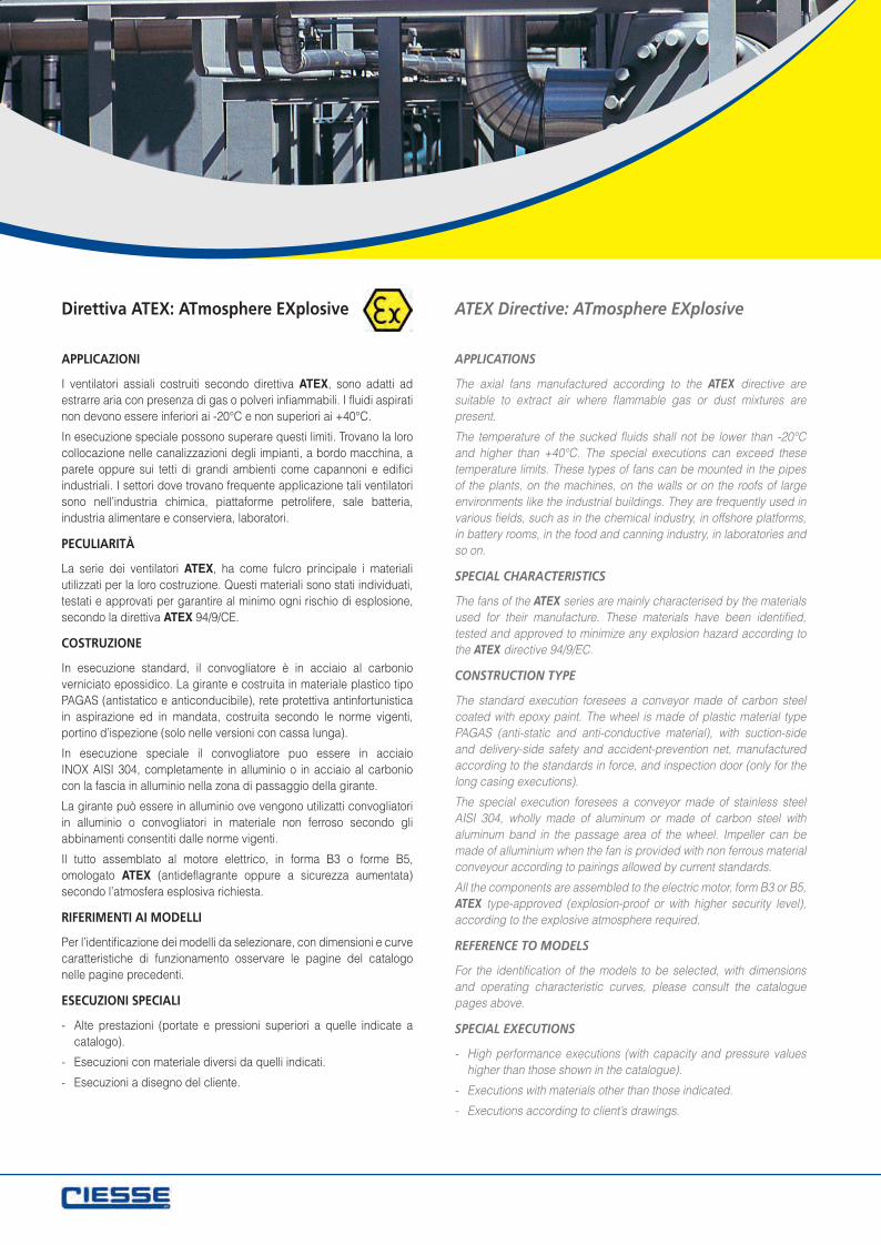
APPLICAZIONI
I ventilatori assiali costruiti secondo direttiva ATEX, sono adatti ad estrarre aria con presenza di gas o polveri infiammabili. I fluidi aspirati non devono essere inferiori ai -20°C e non superiori ai +40°C.
In esecuzione speciale possono superare questi limiti. Trovano la loro collocazione nelle canalizzazioni degli impianti, a bordo macchina, a parete oppure sui tetti di grandi ambienti come capannoni e edifici industriali. I settori dove trovano frequente applicazione tali ventilatori sono nell’industria chimica, piattaforme petrolifere, sale batteria, industria alimentare e conserviera, laboratori.
PECULIARITÀ
La serie dei ventilatori ATEX, ha come fulcro principale i materiali utilizzati per la loro costruzione. Questi materiali sono stati individuati, testati e approvati per garantire al minimo ogni rischio di esplosione, secondo la direttiva ATEX 94/9/CE.
COSTRUZIONE
In esecuzione standard, il convogliatore è in acciaio al carbonio verniciato epossidico. La girante e costruita in materiale plastico tipo PAGAS (antistatico e anticonducibile), rete protettiva antinfortunistica in aspirazione ed in mandata, costruita secondo le norme vigenti, portino d’ispezione (solo nelle versioni con cassa lunga).
In esecuzione speciale il convogliatore puo essere in acciaio INOX AISI 304, completamente in alluminio o in acciaio al carbonio con la fascia in alluminio nella zona di passaggio della girante.
La girante può essere in alluminio ove vengono utilizatti convogliatori in alluminio o convogliatori in materiale non ferroso secondo gli abbinamenti consentiti dalle norme vigenti.
Il tutto assemblato al motore elettrico, in forma B3 o forme B5, omologato ATEX (antideflagrante oppure a sicurezza aumentata) secondo l’atmosfera esplosiva richiesta.
RIFERIMENTI AI MODELLI
Per l’identificazione dei modelli da selezionare, con dimensioni e curve caratteristiche di funzionamento osservare le pagine del catalogo nelle pagine precedenti.
ESECUZIONI SPECIALI
- Alte prestazioni (portate e pressioni superiori a quelle indicate a catalogo).
- Esecuzioni con materiale diversi da quelli indicati.
- Esecuzioni a disegno del cliente.
APPLICATIONS
The axial fans manufactured according to the ATEX directive are suitable to extract air where flammable gas or dust mixtures are present.
The temperature of the sucked fluids shall not be lower than -20°C and higher than +40°C. The special executions can exceed these temperature limits. These types of fans can be mounted in the pipes of the plants, on the machines, on the walls or on the roofs of large environments like the industrial buildings. They are frequently used in various fields, such as in the chemical industry, in offshore platforms, in battery rooms, in the food and canning industry, in laboratories and so on.
SPECIAL CHARACTERISTICS
The fans of the ATEX series are mainly characterised by the materials used for their manufacture. These materials have been identified, tested and approved to minimize any explosion hazard according to the ATEX directive 94/9/EC.
CONSTRUCTION TYPE
The standard execution foresees a conveyor made of carbon steel coated with epoxy paint. The wheel is made of plastic material type PAGAS (anti-static and anti-conductive material), with suction-side and delivery-side safety and accident-prevention net, manufactured according to the standards in force, and inspection door (only for the long casing executions).
The special execution foresees a conveyor made of stainless steel AISI 304, wholly made of aluminum or made of carbon steel with aluminum band in the passage area of the wheel. Impeller can be made of alluminium when the fan is provided with non ferrous material conveyour according to pairings allowed by current standards.
All the components are assembled to the electric motor, form B3 or B5, ATEX type-approved (explosion-proof or with higher security level), according to the explosive atmosphere required.
REFERENCE TO MODELS
For the identification of the models to be selected, with dimensions and operating characteristic curves, please consult the catalogue pages above.
SPECIAL EXECUTIONS
- High performance executions (with capacity and pressure values higher than those shown in the catalogue).
- Executions with materials other than those indicated.
- Executions according to client’s drawings.
Direttiva ATEX: ATmosphere EXplosive ATEX Directive: ATmosphere EXplosive
Ventilatori assiali certificati per l’impiego in zone a rischio di esplosione secondo la direttiva ATEX 94/9/CE
ESECUZIONE ANTIDEFLAGRANTE (ATEX)
È fatto obbligo consultare preventivamente la CIESSE per l’utilizzazione di ventilatori in atmosfere potenzialmente esplosive. I ventilatori costruiti e distribuiti dalla CIESSE possono essere utilizzati in ambienti potenzialmente esplosivi, conformemente alla direttiva ATEX 94/9/CE solo dietro esplicita indicazione del cliente a seguito della valutazione dei rischi e la compilazione di un questionario specifico; in questo caso, sulla targhetta di identificazione del ventilatore viene riportata la stringa ATEX (individuata e/o indicata dal cliente sotto la sua responsabilità) composta da protezione contro il rischio di esplosività, gruppo di appartenenza della apparecchiatura, zona di utilizzo, categoria (protezione dal tipo di gas o polvere potenzialmente esplosivi) e la classe della massima temperatura.
IDENTIFICAZIONE ATMOSFERE E ZONE DI RISCHIO
• G: presenza di gas, vapori e nebbie
• D: presenza di polvere
• G/D: presenza di gas e polveri
In funzione della maggior o minore presenza di atmosfera esplosiva si distinguono tre zone di rischio:
• Zona 0 (per i gas)
• Zona 20 (per le polveri)
Zona con presenza frequente o permanente, quindi con rischio molto elevato. La CIESSE non costruisce ventilatori di categoria 1G - 1D per zone 0 e 20
• Zona 1 (per i gas)
• Zona 21 (per le polveri)
Presenza molto probabile, quindi rischio di esplosione elevato; qui devono essere installate macchine in categoria 2
• Zona 2 (per i gas)
• Zona 22 (per le polveri)
Presenza di atmosfera esplosiva occasionale e di breve durata, quindi rischio normale di esplosione; qui devono essere installate macchine in categoria 3.
CIESSE s.r.l. dichiara altresi che il fascicolo tecnico, dopo approfonditi studi con tecnici specializzati, è stato depositato presso l’organismo di certificazione RWTüW che ha rilasciato il seguente numero di protocollo:
RWTüV - 8 - 05 - ATEX - 0012 - I - CIESSE
Nella gamma CIESSE i modelli dei ventilatori costruibili secondo tale normativa sono i seguenti:
MP - PMA - PMA/C - TE - TR - TP
Axial fans certified for use in potentially explosive areas According to ATEX directive 94/9/EC
INTRODUCTORY NOTES EXPLOSION-PROOF EXECUTION (ATEX)
It is mandatory to prior consult CIESSE for the use of fans in potentially explosive atmospheres.
The fans manufactured and distributed by CIESSE can only be used in potentially explosive environments according to ATEX directive 94/9/EC upon express indication by the client after assessment of the risks and filling of a specific form. In this case the identification plate of the fan will show the string ATEX (identified and/or indicated by the client under his sole responsibility) composed of protection against explosion hazard, equipment group, utilization area, category (protection against the type of potentially explosive gas or dust) and maximum temperature class.
IDENTIFICATION OF ATMOSPHERES AND HAZARDOUS AREAS
• G: presence of gas, vapour andmist
• D: presence of dust
• G/D: presence of gas and dust
According to the higher or lower presence of explosive atmospheres three hazardous areas can be classified:
• Zona 0 (gas)
• Zona 20 (dust)
Frequent or permanent presence of explosive atmospheres, therefore highest explosion hazard. CIESSE does not manufacture category 1G -1D marked fans for areas 0 and 20
• Zona 1 (for gases)
• Zona 21 (for dust)
Highly probable presence of explosive atmospheres, therefore high explosion hazard; these areas require category 2 marked equipment
• Zona 2 (for gases)
• Zona 22 (for dust)
Occasional and short presence of explosive atmospheres, therefore normal explosion hazard; these areas require category 3 marked equipment.
CIESSE s.r.l. declares that after deep studies carried out with qualified engineers the technical dossier has been filed with the certification body RWTüV which issued the following file number:
RWTüV - 8 - 05 - ATEX - 0012 - I - CIESSE
The fan models that can be manufactured according to such standard are the following:
MP - PMA - PMA/C - TE - TR - TP
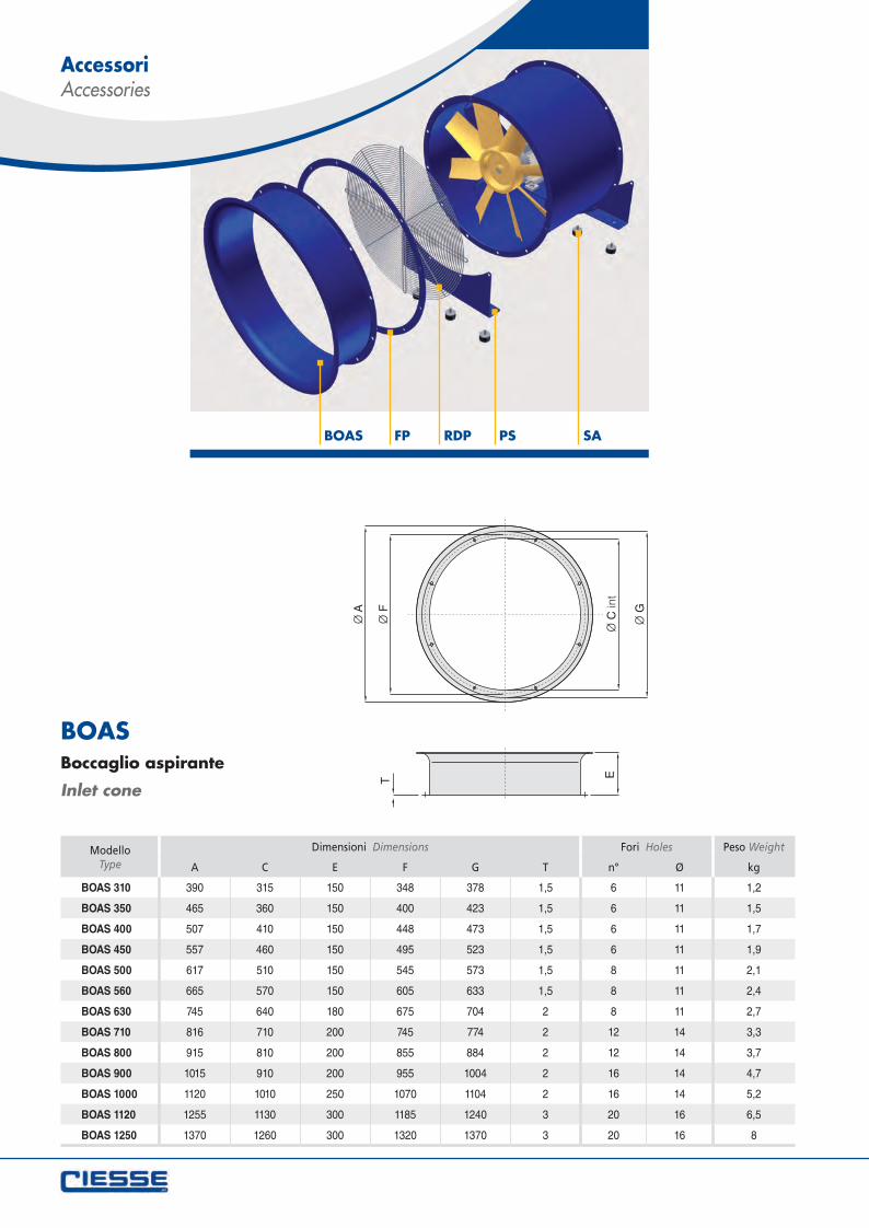
BOAS FP RDP PS SA
BOASBoccaglio aspirante
Inlet cone
ModelloType
Dimensioni Dimensions Fori Holes Peso Weight
A C E F G T n° Ø kg
BOAS 310 390 315 150 348 378 1,5 6 11 1,2
BOAS 350 465 360 150 400 423 1,5 6 11 1,5
BOAS 400 507 410 150 448 473 1,5 6 11 1,7
BOAS 450 557 460 150 495 523 1,5 6 11 1,9
BOAS 500 617 510 150 545 573 1,5 8 11 2,1
BOAS 560 665 570 150 605 633 1,5 8 11 2,4
BOAS 630 745 640 180 675 704 2 8 11 2,7
BOAS 710 816 710 200 745 774 2 12 14 3,3
BOAS 800 915 810 200 855 884 2 12 14 3,7
BOAS 900 1015 910 200 955 1004 2 16 14 4,7
BOAS 1000 1120 1010 250 1070 1104 2 16 14 5,2
BOAS 1120 1255 1130 300 1185 1240 3 20 16 6,5
BOAS 1250 1370 1260 300 1320 1370 3 20 16 8
Accessori Accessories
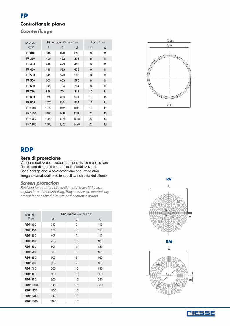
ModelloType
Dimensioni Dimensions Fori Holes
F G M n° Ø
FP 310 348 378 318 6 11
FP 350 400 423 363 6 11
FP 400 448 473 413 6 11
FP 450 495 523 463 6 11
FP 500 545 573 513 8 11
FP 560 605 663 573 8 11
FP 630 745 704 714 8 11
FP 710 855 774 814 12 14
FP 800 955 884 914 12 14
FP 900 1070 1004 914 16 14
FP 1000 1070 1104 1014 16 14
FP 1120 1185 1238 1138 20 16
FP 1250 1320 1378 1258 20 16
FP 1400 1465 1520 1420 20 16
FPControflangia piana
Counterflange
ModelloType
Dimensioni Dimensions
A B C
RDP 300 310 9 110
RDP 350 355 9 110
RDP 400 405 9 110
RDP 450 455 9 130
RDP 500 505 9 130
RDP 560 565 9 150
RDP 600 605 9 160
RDP 630 635 9 160
RDP 700 700 10 190
RDP 800 800 10 200
RDP 900 900 10 250
RDP 1000 1000 10 280
RDP 1120 1120 10
RDP 1250 1250 10
RDP 1400 1400 10
RDPRete di protezioneVengono realizzate a scopo antinfortunistico e per evitare l’intrusione di oggetti estranei nelle canalizzazioni. Sono obbligatorie, a sola eccezione che i ventilatori vengano canalizzati e sotto specifica richiesta del cliente.
Screen protectionRealized for accident prevention and to avoid foreign objects from the channelling. They are always compulsory, except for canalized blowers and costumer orders.
RV
RM
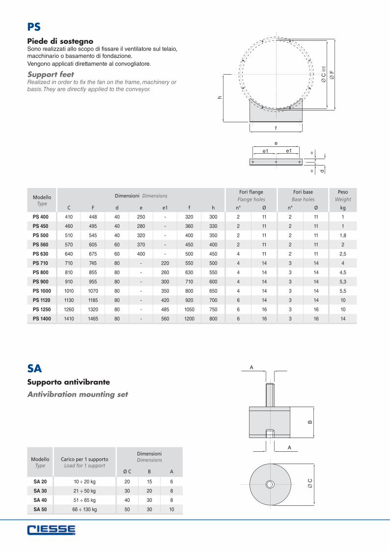
ModelloType
Carico per 1 supporto Load for 1 support
DimensioniDimensions
Ø C B A
SA 20 10 ÷ 20 kg 20 15 6
SA 30 21 ÷ 50 kg 30 20 8
SA 40 51 ÷ 65 kg 40 30 8
SA 50 66 ÷ 130 kg 50 30 10
SASupporto antivibrante
Antivibration mounting set
ModelloType
Dimensioni DimensionsFori flange Fori base Peso
Flange holes Base holes Weight
C F d e e1 f h n° Ø n° Ø kg
PS 400 410 448 40 250 - 320 300 2 11 2 11 1
PS 450 460 495 40 280 - 360 330 2 11 2 11 1
PS 500 510 545 40 320 - 400 350 2 11 2 11 1,8
PS 560 570 605 60 370 - 450 400 2 11 2 11 2
PS 630 640 675 60 400 - 500 450 4 11 2 11 2,5
PS 710 710 745 80 - 220 550 500 4 14 3 14 4
PS 800 810 855 80 - 260 630 550 4 14 3 14 4,5
PS 900 910 955 80 - 300 710 600 4 14 3 14 5,3
PS 1000 1010 1070 80 - 350 800 650 4 14 3 14 5,5
PS 1120 1130 1185 80 - 420 920 700 6 14 3 14 10
PS 1250 1260 1320 80 - 485 1050 750 6 16 3 16 10
PS 1400 1410 1465 80 - 560 1200 800 6 16 3 16 14
PSPiede di sostegnoSono realizzati allo scopo di fissare il ventilatore sul telaio, macchinario o basamento di fondazione. Vengono applicati direttamente al convogliatore.
Support feetRealized in order to fix the fan on the frame, machinery or basis. They are directly applied to the conveyor.
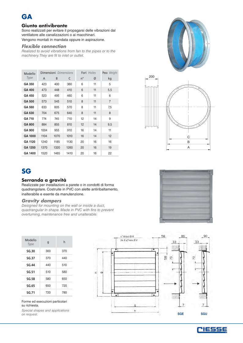
GAGiunto antivibranteSono realizzati per evitare il propagarsi delle vibrazioni dal ventilatore alle canalizzazioni o ai macchinari. Vengono montati in mandata oppure in aspirazione.
Flexible connectionRealized to avoid vibrations from fan to the pipes or to the machinery. They are fit to inlet or outlet.
SGSerranda a gravitàRealizzate per installazioni a parete o in condotti di forma quadrangolare. Costruite in PVC con alette antiribaltamento, inalterabile e esente da manutenzione.
Gravity dampersDesigned for mounting on the wall or inside a duct, quadrangular in shape. Made in PVC with fins to prevent overturning, maintenance free and unalterable.
ModelloType
Dimensioni Dimensions Fori Holes Peso Weight
A B C n° Ø kg
GA 350 423 400 360 6 11 5
GA 400 473 448 410 6 11 5,5
GA 450 523 495 460 6 11 6
GA 500 573 545 510 8 11 7
GA 560 633 605 570 8 11 7,5
GA 630 704 675 640 8 11 8
GA 710 774 745 710 12 14 9
GA 800 884 855 810 12 14 9,5
GA 900 1004 955 910 16 14 11
GA 1000 1104 1070 1010 16 14 12
GA 1120 1240 1185 1130 20 16 16
GA 1250 1370 1320 1260 20 16 19
GA 1400 1520 1465 1410 20 16 22
ModelloType
g h
SG.30 300 370
SG.37 370 440
SG.44 440 510
SG.51 510 580
SG.58 580 650
SG.65 650 720
SG.71 720 780
SGE SGU
Forme ed esecuzioni particolari su richiesta.
Special shapes and applications on request.

Tabella ricambi d’aria Air change table
Numero ricambi per ora consigliati per tipologia di ambienteIl volume d’aria richiesto (in m3/h) è il prodotto tra il volume dell’ambiente (in m3) e il numero di ricambi per ora consigliati.Vedi tabella (i valori sono indicativi).
Number of air changes per hourrecommended for a certain environment typologyThe airflow required (in m3/h) is given by environment volume (in m3) multiplied by recommended number of air changes per hour.See table (values are indicative).
Ambiente Environmentn° ric./h
n° change/h
Allevamenti avicoli Chicken Farm 8 ÷ 15
Allevamenti bovini e suini Cattle Farm 15 ÷ 25
Atri d’albergo - Sale - Corridoi Hotel Halls 4
Autorimesse (parcheggio) Garage (parking) 8
Aurorimesse (riparazioni) Garage (repairing) 10 ÷ 20
Bagni - Docce Lavatoires - Showers 6
Bagni galvanici Galvanic Bath 25 ÷ 30
Banche Banks 4
Caffè - Bar Cafes - Pub 10
Carpenterie - Saldature Carpentry 10 ÷ 12
Cartiere Paper Hill 15 ÷ 20
Centrali termiche Heating Plants 50 ÷ 60
Chiese Churches 10 ÷ 15
Cinema - Teatri Cinemas - Theaters 10 ÷ 15
Colorifici Dyers 15 ÷ 20
Concerie (essicazione pelli) Tannery (drying) 35
Concerie (lavorazione) Tannery (working) 18
Cromatura (locali) Chromium Plating Plants 6 ÷ 10
Fabbrica gomme Rubber Factories 10 ÷ 20
Fabbrica paste alimentari Bakeries 6 ÷ 10
Fabbrica prodotti chimici Chemical Factories 15 ÷ 20
Ambiente Environmentn° ric./h
n° change/h
Fabbriche in genere Factories (general) 6 ÷ 10
Falegnamerie Woodworks 6 ÷ 15
Filature - Tessiture Textile - Factories 5
Fonderie Foundries 20 ÷ 30
Forni da pane (locali con) Bread Ovens 20 ÷ 30
Forni elettrici (locali con) Electric Ovens 30
Forni industriali (locali con) Industrial Ovens 20
Fucine Furnace Rooms 20 ÷ 30
Fungaie Mushroom Bed 10 ÷ 20
Grandi Magazzini Malls 6 ÷ 20
Latte lavorazione Milk (working) 15
Lavanderie - Tintorie Cleaners - Dyers 20 ÷ 30
Macchine e caldaie (locali con) Boiler Houses (engine) 20 ÷ 30
Magazzini per merci deperibili Warehouse for perishable goods 15
Magazzini per merci non deperibili Warehouse for not perishable goods 5
Manifatture tabacchi Tobacco Processing 12
Mense Canteens 4 ÷ 6
Motori (locali con) Motors (engine rooms) 5 ÷ 10
Mulini Mills 15 ÷ 30
Negozi vari Shops 5
Officine Work Shops 6 ÷ 10
Ospedali Hospitals 6
Palestre Gymnasium 10 ÷ 20
Piscine Swimming Pools 20 ÷ 30
Pompe (locali con) Pump Rooms 6 ÷ 12
Ristoranti (cucine) Restaurants (kitchen) 20 ÷ 40
Ristoranti (locali) Restaurants (rooms) 12
Sale d’aspetto Waiting Rooms 10
Sale da ballo Dancing Halls 8 ÷ 16
Sale da gioco Casino 10 ÷ 20
Sale di riunione Meeting Rooms 6 ÷ 8
Sale per convegni Meeting Halls 10 ÷ 20
Scuole Schools 6
Stabilimenti (polverosi) Dusty Plants 10 ÷ 20
Stabilimenti metallurgici Metallurgic Plants 5 ÷ 10
Supermercati Supermarkets 5 ÷ 10
Tipografie Typography 15 ÷ 25
Toilette Toilettes 30
Trasformatori (locali con) Transformer Rooms 12 ÷ 30
Uffici tecnici Technical Rooms 15
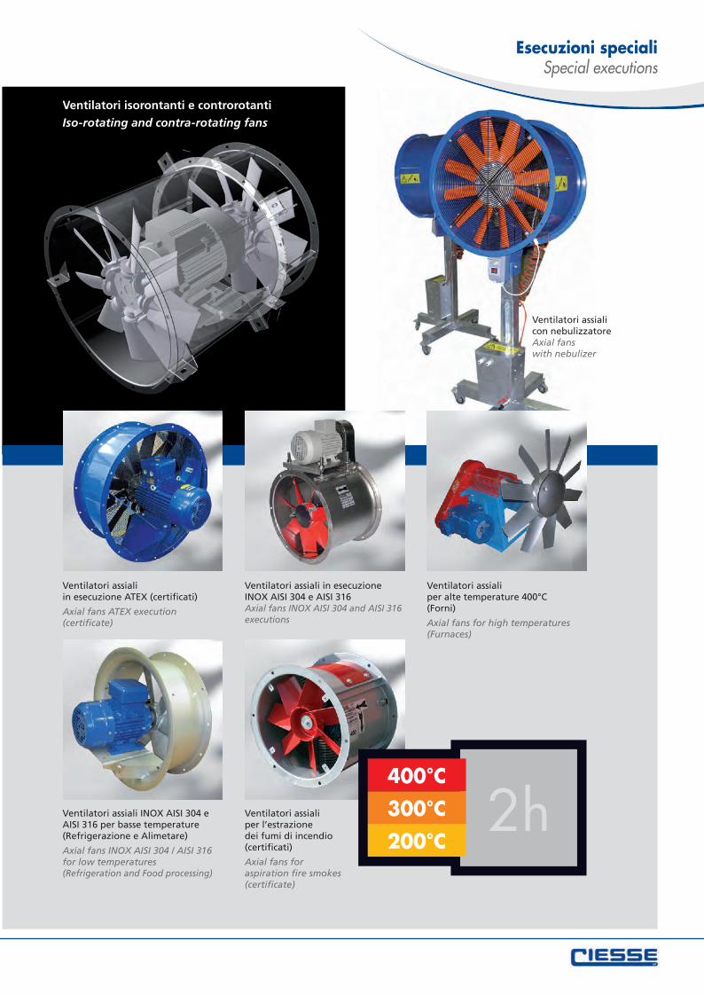
Ventilatori assiali con nebulizzatoreAxial fans with nebulizer
Ventilatori isorontanti e controrotanti
Iso-rotating and contra-rotating fans
Ventilatori assiali INOX AISI 304 e AISI 316 per basse temperature(Refrigerazione e Alimetare)
Axial fans INOX AISI 304 / AISI 316 for low temperatures (Refrigeration and Food processing)
Ventilatori assiali per l’estrazione dei fumi di incendio (certificati)
Axial fans for aspiration fire smokes(certificate)
2h200°C
300°C
400°C
Ventilatori assiali per alte temperature 400°C (Forni)
Axial fans for high temperatures(Furnaces)
Ventilatori assiali in esecuzione INOX AISI 304 e AISI 316Axial fans INOX AISI 304 and AISI 316 executions
Ventilatori assiali in esecuzione ATEX (certificati)
Axial fans ATEX execution (certificate)
Esecuzioni speciali Special executions

CIESSE S.r.l. - 42124 Reggio Emilia (RE) - via Boccioni 5 - tel. +39 0522 517829 - fax +39 0522 [email protected]
www.ciesseventilatori.com
retro copertina_Layout 1 21/05/12 14.15 Pagina 1