
Parker SSD HI Drive Manual - Transtechnik...
232
Hi-drive 2A, 5A, 8A, 10A, 16A 25A, 35A, 45A, 75A 100A, 130A, 155A, 250A user’s manual rev.0.6 April 2010
Transcript of Parker SSD HI Drive Manual - Transtechnik...
Hi-drive 2A, 5A, 8A, 10A, 16A
25A, 35A, 45A, 75A 100A, 130A, 155A, 250A
user’s manual
rev.0.6 April 2010
Parker Hannifin S.p.A Divisione S.B.C Hi-drive User Manual
Page 2 of 233
Parker Parker Hannifin S.p.A. SSDSBC Via Gounod. 1 T: +39 02 361081 http://www.ssddrives. it 20092 Cinisello Balsamo [MI] F: +39 02 36108400 http://www.sbcelettronica.com
Dichiarazione N. Declaration N.
Costruttore Manufacturer
Indirizzo Address
Prod otto Product
Nome del Prodotto Product name
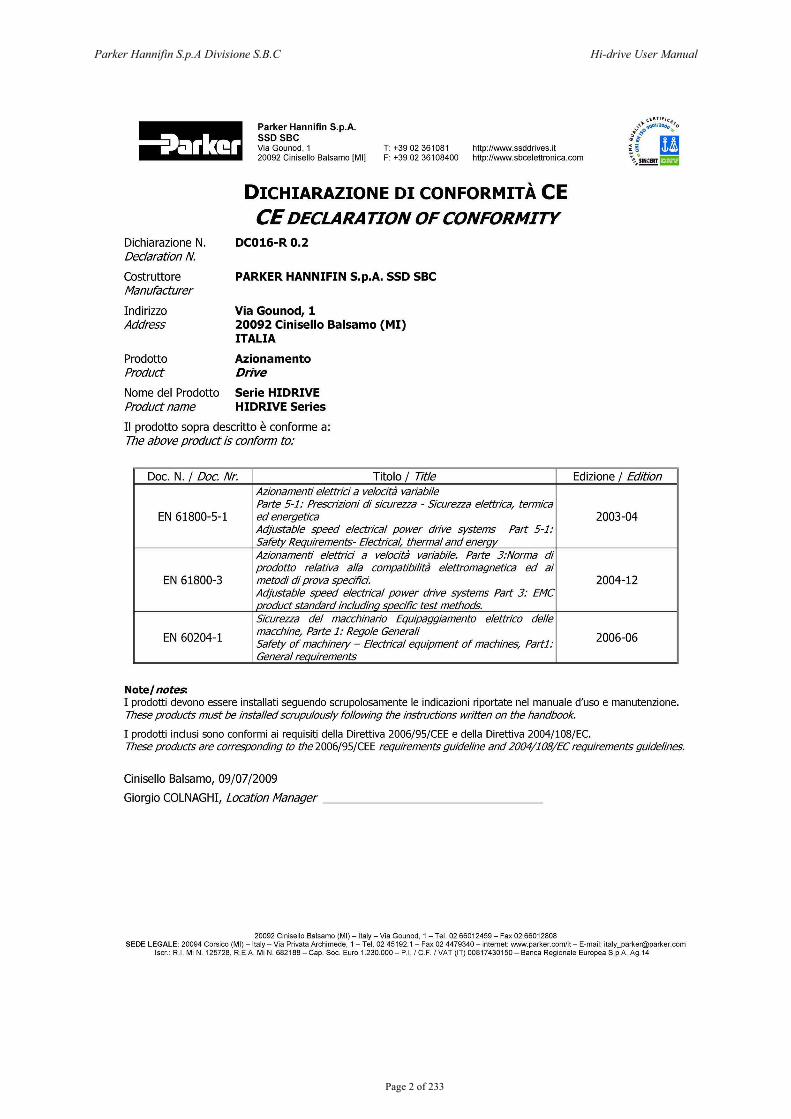
DICHIARAZIONE DI CONFORMITA CE CE DECLARATION OF CONFORMITY
DC016-R0.2
PARKER HANNIFIN S.p.A. SSD SBC
Via Gounod, 1 20092 Cinisello Balsamo (MI) IT ALIA
Azionamento Drive
Serie HIDRIVE HIDRIVE Series
II prodotto sopra descritto e conforme a: The above product is conform to:
Doc. N. I Doc. Nr. Titolo I Title Edizione I Edition Azionamenti elettrici a velocita variabile Parte 5-1: Prescrizioni di sicurezza - Sicurezza elettrica, termica
EN 61800-5-1 ed energetica 2003-04 Adjustable speed electrical power drive systems Part 5-l: Safety Requirements- Electrical. thermal and enerqy Azionamenti elettrici a velocita variabile. Parte 3:Norma di prodotto relativa alia compatibilita elettromagnetica ed ai
EN 61800-3 metodi di prova specifici. 2004-12 Adjustable speed electrical power drive systems Part 3: EMC product standard including specific test methods. Sicurezza del macchinario Equipaggiamento elettrico delle
EN 60204-1 macchine, Parte 1: Regale Generali
2006-06 Safety of machinery- Electrical equipment of machines, Partl: General requirements
Note/ notes: I prodotti devono essere installati seguendo scrupolosamente le indicazioni riportate nel manuale d'uso e manutenzione. These products must be installed scrupulously following the instructions written on the handbook.
I prodotti inclusi sono conformi ai requisiti della Direttiva 2006/95/CEE e della Direttiva 2004/108/EC. These products are corresponding to the 2006/95/CEE requirements guideline and 2004/1 08/EC requirements guidelines.
Cinisello Balsamo, 0910712009
Giorgio COLNAGHI, Location Manager ______________ _
20092 Cinisello Balsamo (MI) -Italy- Via Gounod. 1- Tel. 02 66012459- Fax 02 66012808 SEDE LEGALE: 20094 Corsica (MI) -Italy- Via Privata Archimede, 1 - Tel. 02 45192.1 -Fax 02 4479340- internet: www.parker.comlit- E-mail: [email protected]
lscr .. R. I. Mi N. 125728, REA MiN. 682188- Cap. Soc. Euro 1.230.000- P.l. I C.F. I VAT (IT) 00817430150- Banca Regionale Europea S.p.A. Ag.14

Parker Hannifin S.p.A Divisione S.B.C Hi-drive User Manual
Page 3 of 233
This user manual is for the standard version of the converter. All information in this user manual, including methods, techniques and concepts described herein, are proprietary information of Parker Hannifin Divisione S.B.C. – EME Division and of its licensees, and they shall non be copied or used without express authorization. Parker Hannifin S.p.A. Divisione S.B.C. is committed to a continuous product upgrade and reserves the right to modify products and user manuals at any time without prior notice. No part of this user manual may be howsoever reproduced without previous consent by Parker Hannifin S.p.A. Divisione S.B.C..
Abbreviations
FBK Feedback. Pr… Decimal parameter. b… Binary parameter (bit).
FFW Feedforward, control advance function. R Read parameter. W Write parameter.
Keypad-display Keypad Drive Converter
Cod 1004261430
Parker Hannifin S.p.A Divisione S.B.C Hi-drive User Manual
Page 4 of 233
INDEX
1 SAFETY INSTRUCTIONS........................................................................................9 1.1 Symbols and signals ..................................................................................................9 1.2 General information..................................................................................................9 1.3 Safety instructions for transportation and storage ..............................................10 1.4 Safety instructions for commissioning...................................................................10 1.5 Safety instructions for operation ...........................................................................11 1.6 Safety instructions for maintenance ......................................................................12 1.7 Compatibility with RCD devices............................................................................12 1.8 Applicable standards...............................................................................................13 1.9 Materials and disposal ............................................................................................13 1.10 Warranty..................................................................................................................14
2 PRODUCT INTRODUCTION..................................................................................14 2.1 Product description .................................................................................................14 2.2 Identification............................................................................................................16
3 TECHNICAL DATA ................................................................................................18 3.1 Ambient conditions .................................................................................................18 3.2 Vibrations and shocks.............................................................................................18 3.3 Available models......................................................................................................18 3.4 Power supply............................................................................................................19 3.5 Technical characteristics ........................................................................................20 3.6 Other characteristics...............................................................................................23
4 MOUNTING ............................................................................................................24 4.1 Dimensions and weights..........................................................................................24 4.2 Fastening ..................................................................................................................27 4.3 Mounting instructions.............................................................................................30
5 ELECTRICAL CONNECTIONS..............................................................................31 5.1 Connector pin-out ...................................................................................................31 5.2 Cable lengths and cross sections ............................................................................40 5.3 Protections................................................................................................................42 5.4 Protective Earth connections..................................................................................43 5.5 Power stage supply connection...............................................................................44 5.5.1 Connection to AC 3-phase network ..........................................................................44 5.5.2 Connection to AC 1-phase network ..........................................................................46 5.5.3 Continuous supply connection ..................................................................................47
5.6 External Power supply (fans) .................................................................................49 5.7 Motor connection (MIL connector) .......................................................................50 5.7.1 Motor without stationary brake .................................................................................50 5.7.2 Motor with stationary brake ......................................................................................51
Parker Hannifin S.p.A Divisione S.B.C Hi-drive User Manual
Page 5 of 233
5.8 External braking resistor connection ....................................................................52 5.9 Control stage supply connection ............................................................................55 5.10 Analogue and digital I/Os connection....................................................................56 5.11 Feedback connection ...............................................................................................58 5.11.1 Resolver.....................................................................................................................58 5.11.2 Incremental encoder ..................................................................................................59 5.11.3 Sinusoidal encoder ....................................................................................................60 5.11.4 Sinusoidal encoder + EnDat......................................................................................61 5.11.5 Sinusoidal encoder + Hiperface ................................................................................62 5.11.6 Incremental encoder + hall sensor.............................................................................63 5.11.7 SinCos (one sinwave per pole pitch).........................................................................64
5.12 Auxiliary encoder input connection.......................................................................65 5.13 Connecting converters to the electrical shaft........................................................66 5.14 Serial connection RS422/RS485 .............................................................................67 5.15 Serial connection RS232 .........................................................................................68 5.15.1 Without converter RS232/RS422..............................................................................68 5.15.2 With converter RS232/RS422...................................................................................68
5.16 CAN Bus connection ...............................................................................................69 5.17 Electro-magnetic compliance .................................................................................70 5.17.1 Grounding..................................................................................................................70 5.17.2 Connection cables and shielding ...............................................................................71 5.17.3 Filters.........................................................................................................................72
5.18 Cabling general layout ............................................................................................73
6 STATUS LEDS.......................................................................................................74
7 SUPPLY MODE......................................................................................................74 7.1 “Low voltage” supply..............................................................................................74 7.2 “High voltage” supply.............................................................................................75
8 START-UP..............................................................................................................76 8.1 Setting the default parameters ...............................................................................76 8.2 Selection of motor type ...........................................................................................76 8.3 Changing motor data ..............................................................................................77 8.4 Setting feedback.......................................................................................................77 8.4.1 A feedback, input X6. ...............................................................................................77 8.4.2 B feedback, input X7.................................................................................................77 8.4.3 C Feedback , input X9...............................................................................................78 8.4.4 Speed feedback configuration ...................................................................................78 8.4.5 Position feedback configuration................................................................................79 8.4.6 Digital filter per encoder ...........................................................................................80
8.5 Phasing procedure...................................................................................................80 8.5.1 Type 1 phasing ..........................................................................................................81 8.5.2 Type 2 phasing ..........................................................................................................82 8.5.3 Pico-PLC phasing program .......................................................................................83 8.5.4 Fine phasing ..............................................................................................................83 8.5.5 Phasing procedure for encoder with EnDat o Hiperface interface............................84 8.5.6 Motor phases .............................................................................................................84
8.6 Speed control ...........................................................................................................85
Parker Hannifin S.p.A Divisione S.B.C Hi-drive User Manual
Page 6 of 233
8.7 Speed control adjustment .......................................................................................85
9 ANALOG AND DIGITAL I/OS ................................................................................91 9.1 Digital I/Os ...............................................................................................................91 9.2 Relay outputs ...........................................................................................................91 9.3 Analog outputs.........................................................................................................91
10 DYNAMIC BRAKING ..................................................................................92
11 KEY PARAMETERS ...................................................................................93 11.1 Key parameters .......................................................................................................97
12 OPERATING MODES ...............................................................................107 12.1 Position control......................................................................................................107 12.2 Torque control (operating mode 110)..................................................................110 12.3 Electrical shaft and positioned (op. mod. 120)....................................................111 12.3.1 Speed mode: ............................................................................................................111 12.3.2 Electrical axis: .........................................................................................................111 12.3.3 Positioner.................................................................................................................113 12.3.4 TAB0: profiles in memory ......................................................................................113
12.4 Electronic came (OPM121) ..................................................................................118 12.4.1 Posizionator.............................................................................................................119 12.4.2 Speed mode .............................................................................................................119 12.4.3 CAM1 and CAM2...................................................................................................119
12.5 Electrical shaft and positioned (oper. mode 122) ...............................................128 12.6 Position control via CanBus (operating mode 140)............................................129 12.7 Additional useful functions...................................................................................131 12.7.1 Capturing values......................................................................................................131 12.7.2 Programmable outputs.............................................................................................134 12.7.3 Encoder simulation..................................................................................................135 12.7.4 Motor cogging compensation..................................................................................136 12.7.5 Multiturn absolute encoder phasing on “zero” machine .........................................136 12.7.6 Encoder CAN ..........................................................................................................137 12.7.7 Ramp with “S” profile.............................................................................................139
13 PROGRAMMING DIGITAL INPUTS AND OUTPUTS ..............................140 13.1 The Pico-PLC.........................................................................................................140 13.1.1 Pico-PLC default program ......................................................................................146
13.2 Serial interface.......................................................................................................147 13.3 Communication protocol ......................................................................................148
14 CANBUS INTERFACE..............................................................................153 14.1 SBC Can.................................................................................................................153 14.1.1 Description of fields in real time mode...................................................................154 14.1.2 Description of fields in communication mode ........................................................161 14.1.3 Description of extended message set #2 .................................................................163
14.2 CANopen DSP402 (D version) .............................................................................165 14.2.1 Dictionary object summary of ds301 ......................................................................168 14.2.2 Dictionary object summary of dsp402 ....................................................................170 14.2.2.1 Object 6040h: Controlword.................................................................................173 14.2.2.2 Object 6041h: Statusword ...................................................................................175
Parker Hannifin S.p.A Divisione S.B.C Hi-drive User Manual
Page 7 of 233
14.2.2.3 Object 605Bh: Shutdown option code ................................................................177 14.2.2.4 Object 605Ch: Disable operation option code ....................................................178 14.2.2.5 Object 605Ah: Quick stop option code ...............................................................179 14.2.2.6 Object 605Eh: Fault reaction option code..........................................................179 14.2.2.7 Object 6060h: Modes of operation......................................................................180 14.2.2.8 Object 6061h: Modes of operation display .........................................................180
14.2.3 Functional description .............................................................................................181 14.2.3.1 Modes of operation function ...............................................................................181
14.2.4 Homing mode..........................................................................................................182 14.2.4.1 General information ............................................................................................182 14.2.4.2 Input data description ..........................................................................................182 14.2.4.3 Output data description .......................................................................................183 14.2.4.4 Internal states.......................................................................................................183 14.2.4.4.1 Controlword of homing mode.........................................................................183 14.2.4.4.2 Statusword of homing mode ...........................................................................183
14.2.4.5 Object dictionary entries .....................................................................................184 14.2.4.5.1 Objects defined in this chapter ........................................................................184 14.2.4.5.2 Objects defined in other chapters ....................................................................184
14.2.4.6 Object description ...............................................................................................184 14.2.4.6.1 Object 607Ch: Home offset .............................................................................184 14.2.4.6.2 Object 6098h: Homing method .......................................................................185 14.2.4.6.3 Object 6099h: Homing speeds.........................................................................185 14.2.4.6.4 Object 609Ah: Homing acceleration...............................................................186
14.2.4.7 Functional description .........................................................................................187 14.2.4.8 Homing methods .................................................................................................187 14.2.4.8.1 Method 1: Homing on the negative limit switch and index pulse...................187 14.2.4.8.2 Method 2: Homing on the positive limit switch and index pulse....................188 14.2.4.8.3 Methods 3 and 4: Homing on the positive home switch and index pul. .........188 14.2.4.8.4 Methods 5 and 6: Homing on the negative home switch and index pul. ........189 14.2.4.8.5 Methods 7 to 14: Homing on the home switch and index pulse .....................189 14.2.4.8.6 Methods 15 and 16: Reserved .........................................................................190 14.2.4.8.7 Methods 17 to 30: Homing without an index pulse ........................................191 14.2.4.8.8 Methods 31 and 32: Reserved .........................................................................191 14.2.4.8.9 Methods 33 to 34: Homing on the index pulse ...............................................191 14.2.4.8.10 Method 35: Homing on the current position ...............................................191
14.2.5 Profile position mode ..............................................................................................192 14.2.5.1 Internal states.......................................................................................................192 14.2.5.1.1 Controlword of profile position mode ............................................................192 14.2.5.1.2 Statusword of profile position mode ...............................................................192
14.2.5.2 Object dictionary entries .....................................................................................193 14.2.5.2.1 Objects defined in this chapter ........................................................................193 14.2.5.2.2 Object 607Ah: Target position........................................................................193 14.2.5.2.3 Object 6081h: Profile velocity ........................................................................194 14.2.5.2.4 Object 6083h: Profile acceleration..................................................................194 14.2.5.2.5 Object 6084h: Profile deceleration..................................................................195 14.2.5.2.6 Object 6085h: Quick stop deceleration ...........................................................195 14.2.5.2.7 Object 6086h: Motion profile type..................................................................196
14.2.5.3 Functional description .........................................................................................196 14.2.5.4 Functional description .........................................................................................198
14.2.6 Interpolated Position Mode .....................................................................................200 14.2.6.1 Object 60C0h: Interpolation sub mode select .....................................................201
Parker Hannifin S.p.A Divisione S.B.C Hi-drive User Manual
Page 8 of 233
14.2.6.2 Object 60C1h: Interpolation data record.............................................................201 14.2.7 Drive parameters .....................................................................................................204 14.2.8 CANopen monitor by ASCII commands ................................................................205
15 PROGRAMMING THE CONVERTER THROUGH A PC ..........................207 15.1 MotionWiz..............................................................................................................208 15.2 Hyperterminal connection....................................................................................209 15.2.1 Creating and setting a connection ...........................................................................209 15.2.2 ASCII protocol port RS-232 ...................................................................................211
16 USE OF (OPTIONAL) KEYPAD................................................................214
17 APPENDIX A : CONVENTIONS ...............................................................217
18 APPENDIX B : FLASH INFORMATION ...................................................217
19 APPENDIX C : SOFTWARE TIMING........................................................218
20 APPENDIX D : ALARMS ..........................................................................219
21 APPENDIX E : CONTINUOUS WORKING ...............................................221
22 APPENDIX F : EXTERNAL CAPACITOR ................................................224
23 APPENDIX G : OPTION “R” FOR SAFE DISABLE FUNCTION .............225 23.1 Introduction ...........................................................................................................225 23.2 Signals description.................................................................................................226 23.3 Drive function blocks ............................................................................................227 23.4 Connections............................................................................................................228 23.5 Operation, sequence and timing ..........................................................................228 23.6 Example..................................................................................................................230 23.7 Test and maintenance ...........................................................................................230
24 APPENDIX H : RETENTIVE VARIABLE ..................................................231
25 HISTORY OF MANUAL REVISIONS........................................................232
Parker Hannifin S.p.A Divisione S.B.C Hi-drive User Manual
Page 9 of 233
1 Safety instructions
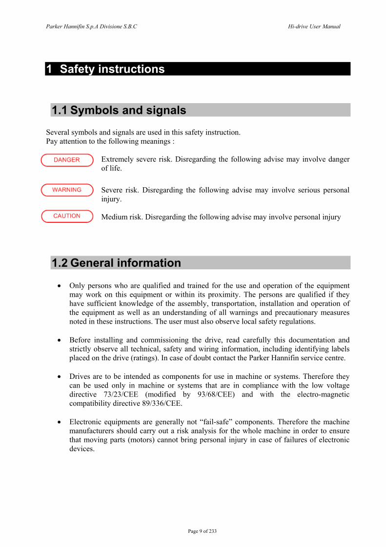
1.1 Symbols and signals Several symbols and signals are used in this safety instruction. Pay attention to the following meanings :
Extremely severe risk. Disregarding the following advise may involve danger of life.
Severe risk. Disregarding the following advise may involve serious personal injury. Medium risk. Disregarding the following advise may involve personal injury
1.2 General information
• Only persons who are qualified and trained for the use and operation of the equipment may work on this equipment or within its proximity. The persons are qualified if they have sufficient knowledge of the assembly, transportation, installation and operation of the equipment as well as an understanding of all warnings and precautionary measures noted in these instructions. The user must also observe local safety regulations.
• Before installing and commissioning the drive, read carefully this documentation and
strictly observe all technical, safety and wiring information, including identifying labels placed on the drive (ratings). In case of doubt contact the Parker Hannifin service centre.
• Drives are to be intended as components for use in machine or systems. Therefore they
can be used only in machine or systems that are in compliance with the low voltage directive 73/23/CEE (modified by 93/68/CEE) and with the electro-magnetic compatibility directive 89/336/CEE.
• Electronic equipments are generally not “fail-safe” components. Therefore the machine
manufacturers should carry out a risk analysis for the whole machine in order to ensure that moving parts (motors) cannot bring personal injury in case of failures of electronic devices.
Parker Hannifin S.p.A Divisione S.B.C Hi-drive User Manual
Page 10 of 233
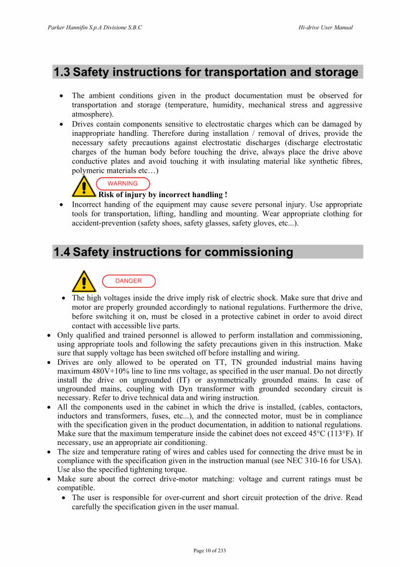
1.3 Safety instructions for transportation and storage
• The ambient conditions given in the product documentation must be observed for transportation and storage (temperature, humidity, mechanical stress and aggressive atmosphere).
• Drives contain components sensitive to electrostatic charges which can be damaged by inappropriate handling. Therefore during installation / removal of drives, provide the necessary safety precautions against electrostatic discharges (discharge electrostatic charges of the human body before touching the drive, always place the drive above conductive plates and avoid touching it with insulating material like synthetic fibres, polymeric materials etc…)
Risk of injury by incorrect handling ! • Incorrect handing of the equipment may cause severe personal injury. Use appropriate
tools for transportation, lifting, handling and mounting. Wear appropriate clothing for accident-prevention (safety shoes, safety glasses, safety gloves, etc...).
1.4 Safety instructions for commissioning
• The high voltages inside the drive imply risk of electric shock. Make sure that drive and
motor are properly grounded accordingly to national regulations. Furthermore the drive, before switching it on, must be closed in a protective cabinet in order to avoid direct contact with accessible live parts.
• Only qualified and trained personnel is allowed to perform installation and commissioning, using appropriate tools and following the safety precautions given in this instruction. Make sure that supply voltage has been switched off before installing and wiring.
• Drives are only allowed to be operated on TT, TN grounded industrial mains having maximum 480V+10% line to line rms voltage, as specified in the user manual. Do not directly install the drive on ungrounded (IT) or asymmetrically grounded mains. In case of ungrounded mains, coupling with Dyn transformer with grounded secondary circuit is necessary. Refer to drive technical data and wiring instruction.
• All the components used in the cabinet in which the drive is installed, (cables, contactors, inductors and transformers, fuses, etc...), and the connected motor, must be in compliance with the specification given in the product documentation, in addition to national regulations. Make sure that the maximum temperature inside the cabinet does not exceed 45°C (113°F). If necessary, use an appropriate air conditioning.
• The size and temperature rating of wires and cables used for connecting the drive must be in compliance with the specification given in the instruction manual (see NEC 310-16 for USA). Use also the specified tightening torque.
• Make sure about the correct drive-motor matching: voltage and current ratings must be compatible. • The user is responsible for over-current and short circuit protection of the drive. Read
carefully the specification given in the user manual.
Parker Hannifin S.p.A Divisione S.B.C Hi-drive User Manual
Page 11 of 233
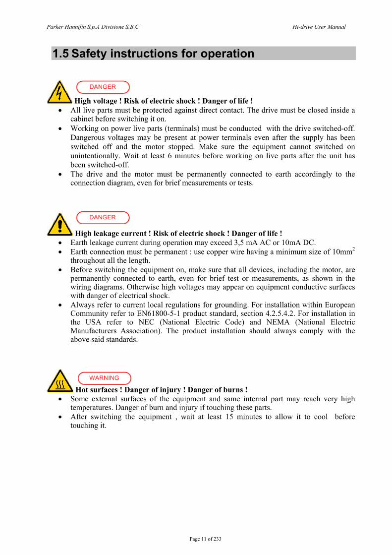
1.5 Safety instructions for operation
High voltage ! Risk of electric shock ! Danger of life ! • All live parts must be protected against direct contact. The drive must be closed inside a
cabinet before switching it on. • Working on power live parts (terminals) must be conducted with the drive switched-off.
Dangerous voltages may be present at power terminals even after the supply has been switched off and the motor stopped. Make sure the equipment cannot switched on unintentionally. Wait at least 6 minutes before working on live parts after the unit has been switched-off.
• The drive and the motor must be permanently connected to earth accordingly to the connection diagram, even for brief measurements or tests.
High leakage current ! Risk of electric shock ! Danger of life ! • Earth leakage current during operation may exceed 3,5 mA AC or 10mA DC. • Earth connection must be permanent : use copper wire having a minimum size of 10mm2
throughout all the length. • Before switching the equipment on, make sure that all devices, including the motor, are
permanently connected to earth, even for brief test or measurements, as shown in the wiring diagrams. Otherwise high voltages may appear on equipment conductive surfaces with danger of electrical shock.
• Always refer to current local regulations for grounding. For installation within European Community refer to EN61800-5-1 product standard, section 4.2.5.4.2. For installation in the USA refer to NEC (National Electric Code) and NEMA (National Electric Manufacturers Association). The product installation should always comply with the above said standards.
Hot surfaces ! Danger of injury ! Danger of burns ! • Some external surfaces of the equipment and same internal part may reach very high
temperatures. Danger of burn and injury if touching these parts. • After switching the equipment , wait at least 15 minutes to allow it to cool before
touching it.

Parker Hannifin S.p.A Divisione S.B.C Hi-drive User Manual
Page 12 of 233
Dangerous movements ! Danger of life ! • Dangerous movements can be caused by faulty control of the connected motor.
Same common example are :
Improper or wrong installation and wiring Wrong input parameters before or during operation (programming) Defective components (drive, motor, wires, sensors, etc...) Incorrect control (software or firmware errors)
• In order to prevent personal injury due to unintended dangerous motor movements, pay the
maximum attention and work on the machine with a qualified and tested safety system :
Isolate the drive power connection. Mount the emergency stop switch in the immediate reach of the operator. Verify that the
emergency stop works before start-up. Don’t operate the machine if the emergency stop is not working.
Install properly fences, guards, coverings and light barriers in order to prevent people from accidentally entering the machine’s range of motion.
Secure vertical axes against falling or dropping after switching off the motor power Make sure that the drives are brought to a safe standstill before accessing or entering the
danger zone.
1.6 Safety instructions for maintenance
• It is extremely dangerous to remove covers or part of the external enclosure from the
equipment. Risk of personal injury. The warranty immediately decay. • In case of malfunction consult the alarm list described in the user manual or address
Parker Hannifin. The drives are not field repairable.
1.7 Compatibility with RCD devices
The use of RCD (Residual Current Devices) is strongly not recommended. If the use of RCD is mandatory, use type B only (for DC and AC prospective earth current). Set the trip level at 300mA (fire protection level) or more. Setting the trip level at 30mA (protection level against direct contact) is possible only using time-delayed RCD and low leakage current EMC filters, but in any case the drives are not guaranteed to operate with 30mA trip level.
Parker Hannifin S.p.A Divisione S.B.C Hi-drive User Manual
Page 13 of 233
1.8 Applicable standards Safety 73/23/CEE directive modified by 93/68/CEE
Low voltage directive
EN 50178 Electronic equipment for use in power installations EN 60204-1 Safety of machinery – Electrical equipment of machines – Part 1:
General requirements EN 61800-2 Adjustable speed electrical power drive systems – Part 2: General
requirements – Rating specifications for low voltage adjustable frequency a.c. power drive systems
EN 61800-5-1 Adjustable speed electrical power drive systems – safety requirements, thermal and energy
EN 954-1 / ISO 13849-1 Safety of Machinery - Safety-related Parts of Control Systems - Part 1: General Principles for Design provides such a set of categories
UL508C (USA) Power Conversion Equipment CSA22.2 Nr. 14-05 (Canada) Power Conversion Equipment Electromagnetic Compatibility (Immunity/Emission) 89/336/CEE directive EMC directive EN 61800-3 Adjustable speed electrical power drive systems. Part 3 : EMC
product standard including specific test method The drives are to be intended as components to be used in a second environment (industrial environment) and category C3, together with specific EMC filters and installed accordingly to the recommendation given in the user manual. When used in the first environment (residential / commercial environment), drives may produce radio-frequency interference dangerous for other equipments : additional filtering measures must be implemented by the user.
1.9 Materials and disposal - zinc coated steel sheet, thickness 1mm and 2mm - extruded aluminium AlSi - ABS “Novodur” thickness 2mm minimum - adhesive polycarbonate (label) Electrolytic capacitor contain electrolyte and printed circuit boards contain lead, both of which are classified as hazardous waste and must be removed and handled according to local regulations.
The S.B.C. division of the Parker Hannifin Company, together with local distributors and in accordance with EU standard 2002/96/EC, undertakes to withdraw and dispose of its products, fully respecting environmental considerations.
Parker Hannifin S.p.A Divisione S.B.C Hi-drive User Manual
Page 14 of 233
1.10 Warranty The warranty duration if 1 (one) year. The converter must not be opened, accessed or modified in any of its part. Any attempt to do so would cause the 1-year warranty to be cancelled with immediate effect.. Parker Hannifin declines any responsibility for damages that may be caused by inappropriate use of the converter.
2 PRODUCT INTRODUCTION
2.1 Product description HiDrive is the result of in-depth research and development and of a longstanding hands-on experience combined with a wide-ranging market research. HiDrive focuses on the market of applications requiring a high degree of precision and accuracy, high performance, flexibility to connect to various supervision and control systems, high torques and custom drive arrangements based on specific applications. HiDrive is a range of high performing, completely digital drives used both in closed-loop vector control mode and as servo drive (available as standard). The range offering is complete in several sizes, with 3-phase, 1-phase or continuous power. The drive can be run in the following standard modes (usually called “operating modes”) , both when it is used to control regenerative asynchronous motors or brushless motors: torque control, speed, positioner with trapezoidal profile, variable ratio/phase control electrical shaft, electronic cams, positioner via CanBus. These operating modes are available both in vector control and as servo drive. The drive comes with many other standard functions, such as S ramps, value capturing and comparison functions. Only one parameter setting is used to chose an operating mode or to select between asynchronous or brushless motor control. The standard HiDrive is equipped with three independent encoder ports, to which the following devices can be connected: resolver, incremental encoder, less wiring, sincos, sincos+absolute Endat mono and multirun, sincos+absolute Hyperface mono and multirun. Also available are a second incremental encoder or sincos or frequency/sign input, whereas encoder RS422 repetition has a high maximum output frequency and programmable pulses per revolution. In order to have more connection flexibility of HiDrive parameters with the external word (inputs/outputs), the drive is provided as standard with a PLC (called “picoPLC”). The picoPLC has a capacity of up to 256 instructions, scanning time of 6.144 ms, Ladder and Instruction List programming languages. It is a very powerful tool to implement a simple per sequence logic in the drive. For complex applications, the drive can house (as option) a full-IEC1131 environment (called “LogicLab”), that can be programmed using all 5 standard and multitasking languages (6 tasks with different cyclic execution times). The drive is equipped with 3 leds providing an immediate display of the drive status, also without keypad on the drive. HiDrive can also be equipped with an optional removable alphanumeric keypad with internal memory to display parameters, send commands, write picoPLC instructions and providing alarm diagnostic functions. Through the keypad it is also possible to “clone” parameters and picoPLC programs between drives.

Parker Hannifin S.p.A Divisione S.B.C Hi-drive User Manual
Page 15 of 233
An advanced software tool (called “MotionWiz”) is also available free of charge to be able to connect the drive to the PC via serial link RS422 or RS232. Such tool allows to interactively configure the drive, to program the picoPLC and to display the variables by means of a software oscilloscope. Besides the features described above, the drive comes complete with the following standard and optional functions:
Automatic cogging compensation functions High, adjustable resolution of position loop Analogue inputs and outputs, digital inputs and outputs, relay outputs Serial communication port RS232 Serial communication port RS422/485 CanOpen DS301 or SBCCAN Fieldbus (standard) Three option slots I/O Expansions (optional) Profibus-DP Fieldbus (optional) Integrated EMI filter to HID8 (included) Low voltage power supply Separate 24Vdc supply to the control logic Programmable power supply for motor feedback device Encoder input voltage sensing to automatically compensate for any voltage drops in the
encoder supply due to the cable length Dedicated motor braking driving port PWM up to 16kHz

Parker Hannifin S.p.A Divisione S.B.C Hi-drive User Manual
Page 16 of 233
2.2 Identification The converters of the Hi-drive series are available in 13 models: HID2, HID5, HID8, HID10, HID16, HID25, HID35, HID45, HID75, HID100, HID130, HID155 and HID250. The number that follows the HID abbreviation corresponds to the rated current of the converter in amperes. Use the following table to specify the order code:
HID 2 S S X 5 D E Y1 Y2 Y3 R M 8 H 10 16 25 35 45 75 100 …
where:
HID Servodrive series X ATEX type drive
2 Drive size (nominal current, up to 3 digits: 2, 5, 8, 10, 16, 25, 35, 45, 75, 100, 130, 155, 250)
S SBC CAN protocol (standard) D CANopen protocol (DS402) S Second encoder input for SinCos signals – 1 Vpp E Second encoder input for quadrature digital signals – RS422 H Second encoder input for quadrature digital signals + Hall sensor signals
Y1
Optional board in
Slot N. 1
Y2
Optional board in
Slot N. 2
Y3
Optional board in
Slot N. 3
Code optional boards: P = profibus DP - P I = I/O 8DI+8DO –I E1 = Powerlink (n.a.) E2 = Sercos 3 (n.a.) E3 = CIP (n.a.) E4 = Profinet (n.a.) E5 = Ethercat (n.a.) S = Sercos D = Devicenet (n.a.) C1 = Robox board up to 1,5 axis (with CANopen DS402) [in 3 Slot] C2 = Robox board up to 4 axis (with CANopen DS402) [su 3 Slot] C3 = Robox board up to 32 axis (with CANopen DS402) [su 3 Slot] C4 = Robox board up to TBD (with CANopen DS402) (n.a.) [in 3 Slot] C5 = Robox board up to TBD (with CANopen DS402) (n.a.) [in 3 Slot] C6 = Robox board up to TBD (with CANopen DS402) (n.a.) [in 3 Slot]
R Internal safety relay M Memory area for ritentive variables
Parker Hannifin S.p.A Divisione S.B.C Hi-drive User Manual
Page 17 of 233
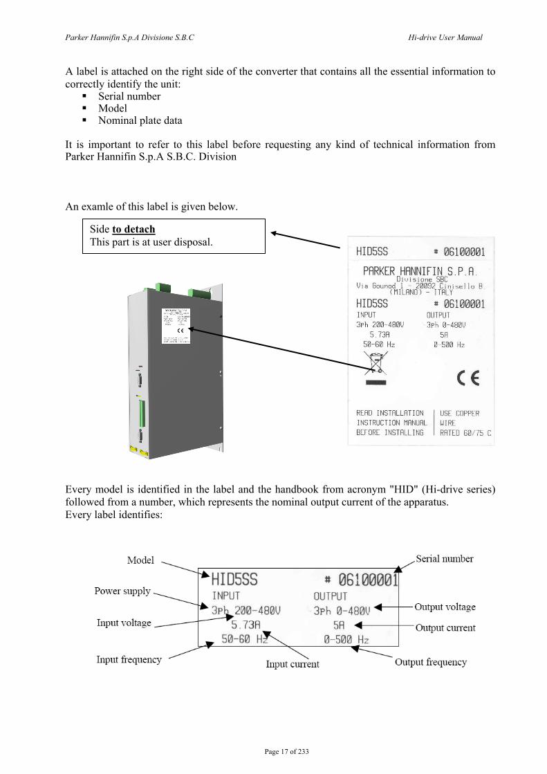
A label is attached on the right side of the converter that contains all the essential information to correctly identify the unit:
Serial number Model Nominal plate data
It is important to refer to this label before requesting any kind of technical information from Parker Hannifin S.p.A S.B.C. Division An examle of this label is given below.
Every model is identified in the label and the handbook from acronym "HID" (Hi-drive series) followed from a number, which represents the nominal output current of the apparatus. Every label identifies:
Side to detach This part is at user disposal.

Parker Hannifin S.p.A Divisione S.B.C Hi-drive User Manual
Page 18 of 233
3 TECHNICAL DATA
3.1 Ambient conditions
operation 3K3 Class, 0 … +45 °C (+32 …+113 °F) storage 1K4 Class, -25 … +55 °C (-4 …+131 °F) temperature transportation 2K3 Class, -25 … +70 °C (-13…+158 °F) operation 3K3 Class, 5-85 % without ice and condensation storage 1K3 Class, 5-95 % without ice and condensation humidity transportation 2K3 Class, 95% a 40°C
altitude (*) ≤ 1000 m slm (≤ 3281 feet asl)
protection degree IP20 (only in close electric cabinet) UL open type equipment
pollution degree 2 or lower (no conductive dust allowed) (*) For higher installation altitude, derate the output current by 1.5% each 100m up to 2000m maximum
3.2 Vibrations and shocks
frequency [Hz] amplitude [mm] acceleration [m/s2] 2 ≤ f < 9 0,3 - operation
(3M1 class) 9 ≤ f < 200 - 1 2 ≤ f < 9 3,5 -
9 ≤ f < 200 - 10 200 ≤ f < 500 - 15
transportation (2M1 class)
free fall 0,25m max
3.3 Available models
AVAILABLE MODELS AND DIMENSIONS length [mm] width [mm] depth [mm] (*) models
SIZE 1 87 360 (428**) 227 HID2-HID5-HID8-HID10SIZE 2 122 360 (428**) 227 HID16-HID25 SIZE 3 227 360 (428**) 227 HID35-HID45 SIZE 4 250 660 320 HID75 SIZE 5 250 720 365 HID100-HID130-HID155SIZE 6 600 1145 465 HID250
(*) without connector and keypad (**) with fixing flange
Parker Hannifin S.p.A Divisione S.B.C Hi-drive User Manual
Page 19 of 233
3.4 Power supply
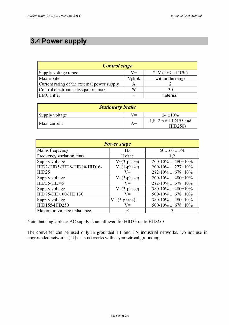
Control stage Supply voltage range V= 24V (-0%...+10%) Max ripple Vpkpk within the range Current rating of the external power supply A 2 Control electronics dissipation, max W 30 EMC Filter - internal
Stationary brake
Supply voltage V= 24 ±10%
Max. current A= 1,8 (2 per HID155 and HID250)
Power stage Mains frequency Hz 50…60 ± 5% Frequency variation, max Hz/sec 1,2 Supply voltage HID2-HID5-HID8-HID10-HID16-HID25
V~(3-phase) V~(1-phase)
V=
200-10% ... 480+10% 200-10% ... 277+10% 282-10% ... 678+10%
Supply voltage HID35-HID45
V~(3-phase) V=
200-10% ... 480+10% 282-10% ... 678+10%
Supply voltage HID75-HID100-HID130
V~(3-phase) V=
380-10% ... 480+10% 500-10% ... 678+10%
Supply voltage HID155-HID250
V~ (3-phase) V=
380-10% ... 480+10% 500-10% ... 678+10%
Maximum voltage unbalance % 3 Note that single phase AC supply is not allowed for HID35 up to HID250 The converter can be used only in grounded TT and TN industrial networks. Do not use in ungrounded networks (IT) or in networks with asymmetrical grounding.
Parker Hannifin S.p.A Divisione S.B.C Hi-drive User Manual
Page 20 of 233
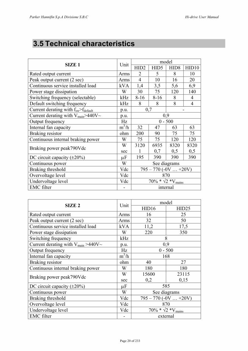
3.5 Technical characteristics
model SIZE 1 Unit HID2 HID5 HID8 HID10 Rated output current Arms 2 5 8 10 Peak output current (2 sec) Arms 4 10 16 20 Continuous service installed load kVA 1,4 3,5 5,6 6,9 Power stage dissipation W 30 75 120 140 Switching frequency (selectable) kHz 8-16 8-16 8 4 Default switching frequency kHz 8 8 8 4 Current derating with fsw>fdefault p.u. 0,7 - Current derating with Vmain>440V~ p.u. 0,9 Output frequency Hz 0 - 500 Internal fan capacity m3/h 32 47 63 63 Braking resistor ohm 200 90 75 75 Continuous internal braking power W 75 75 120 120
Braking power peak790Vdc W sec
3120 1
6935 0,7
8320 0,5
8320 0,5
DC circuit capacity (±20%) μF 195 390 390 390 Continuous power W See diagrams Braking threshold Vdc 795 – 770 (-0V … +20V) Overvoltage level Vdc 870 Undervoltage level Vdc 70% * √2 *Vmains EMC filter - internal
model SIZE 2 Unit HID16 HID25 Rated output current Arms 16 25 Peak output current (2 sec) Arms 32 50 Continuous service installed load kVA 11,2 17,5 Power stage dissipation W 220 350 Switching frequency kHz 8 Current derating with Vmain >440V~ p.u. 0,9 Output frequency Hz 0 - 500 Internal fan capacity m3/h 168 Braking resistor ohm 40 27 Continuous internal braking power W 180 180
Braking power peak790Vdc W sec
15600 0,2
23115 0,15
DC circuit capacity (±20%) μF 585 Continuous power W See diagrams Braking threshold Vdc 795 – 770 (-0V … +20V) Overvoltage level Vdc 870 Undervoltage level Vdc 70% * √2 *Vmains EMC filter - external
Parker Hannifin S.p.A Divisione S.B.C Hi-drive User Manual
Page 21 of 233
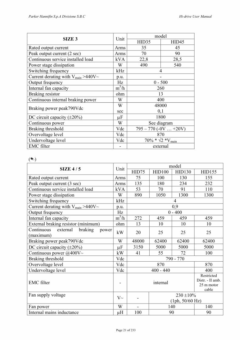
model SIZE 3 Unit HID35 HID45
Rated output current Arms 35 45 Peak output current (2 sec) Arms 70 90 Continuous service installed load kVA 22,8 28,5 Power stage dissipation W 490 540 Switching frequency kHz 4 Current derating with Vmain >440V~ p.u. - Output frequency Hz 0 - 500 Internal fan capacity m3/h 260 Braking resistor ohm 13 Continuous internal braking power W 400
Braking power peak790Vdc W sec
48000 0,1
DC circuit capacity (±20%) μF 1800 Continuous power W See diagram Braking threshold Vdc 795 – 770 (-0V … +20V) Overvoltage level Vdc 870 Undervoltage level Vdc 70% * √2 *Vmain EMC filter - external ()
model SIZE 4 / 5 Unit HID75 HID100 HID130 HID155 Rated output current Arms 75 100 130 155 Peak output current (3 sec) Arms 135 180 234 232 Continuous service installed load kVA 53 70 91 110 Power stage dissipation W 890 1050 1300 1300 Switching frequency kHz 4 Current derating with Vmain >440V~ p.u. 0,9 Output frequency Hz 0 - 400 Internal fan capacity m3/h 272 459 459 459 External braking resistor (minimum) ohm 13 10 10 10 Continuous external braking power (maximum) kW 20 25 25 25
Braking power peak790Vdc W 48000 62400 62400 62400 DC circuit capacity (±20%) μF 3150 5000 5000 5000 Continuous power @400V~ kW 41 55 72 100 Braking threshold Vdc 790 - 770 Overvoltage level Vdc 870 870 Undervoltage level Vdc 400 - 440 400
EMC filter - internal Restricted
Distr. - II amb. 25 m motor
cable Fan supply voltage V~ - 230 ±10%
(1ph, 50/60 Hz) Fan power W - 140 140 Internal mains inductance µH 100 90 90
Parker Hannifin S.p.A Divisione S.B.C Hi-drive User Manual
Page 22 of 233
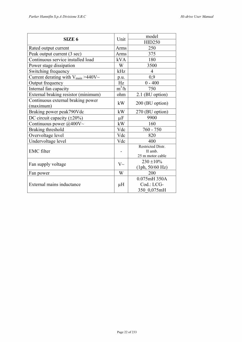
model SIZE 6 Unit HID250
Rated output current Arms 250 Peak output current (3 sec) Arms 375 Continuous service installed load kVA 180 Power stage dissipation W 3500 Switching frequency kHz 4 Current derating with Vmain >440V~ p.u. 0,9 Output frequency Hz 0 - 400 Internal fan capacity m3/h 750 External braking resistor (minimum) ohm 2.1 (BU option) Continuous external braking power (maximum) kW 200 (BU option)
Braking power peak790Vdc kW 270 (BU option) DC circuit capacity (±20%) μF 9900 Continuous power @400V~ kW 160 Braking threshold Vdc 760 - 750 Overvoltage level Vdc 820 Undervoltage level Vdc 400
EMC filter - Restricted Distr.
II amb. 25 m motor cable
Fan supply voltage V~ 230 ±10% (1ph, 50/60 Hz)
Fan power W 200
External mains inductance µH 0.075mH 350A
Cod.: LCG-350_0,075mH
Parker Hannifin S.p.A Divisione S.B.C Hi-drive User Manual
Page 23 of 233
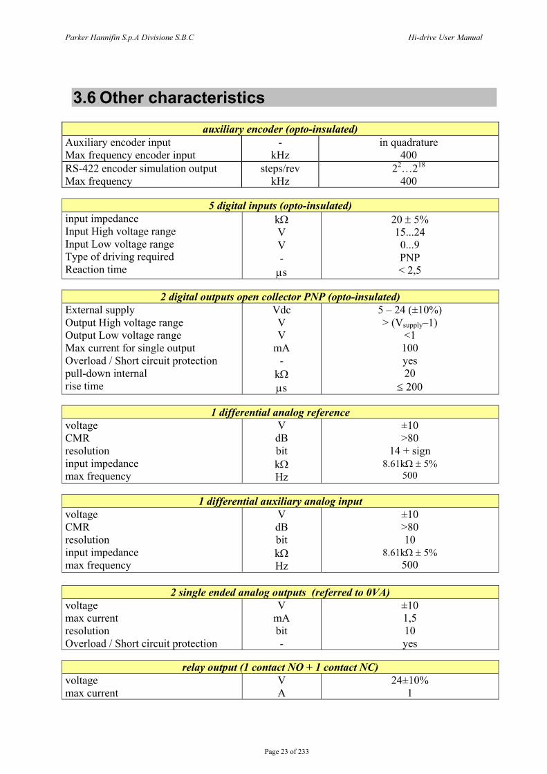
3.6 Other characteristics
auxiliary encoder (opto-insulated) Auxiliary encoder input Max frequency encoder input
- kHz
in quadrature 400
RS-422 encoder simulation output Max frequency
steps/rev kHz
22…218 400
5 digital inputs (opto-insulated)
input impedance Input High voltage range Input Low voltage range Type of driving required Reaction time
kΩ V V - μs
20 ± 5% 15...24 0...9 PNP < 2,5
2 digital outputs open collector PNP (opto-insulated)
External supply Output High voltage range Output Low voltage range Max current for single output Overload / Short circuit protection pull-down internal rise time
Vdc V V
mA -
kΩ μs
5 – 24 (±10%) > (Vsupply–1)
<1 100 yes 20
≤ 200
1 differential analog reference voltage CMR resolution input impedance max frequency
V dB bit kΩ Hz
±10 >80
14 + sign 8.61kΩ ± 5%
500
1 differential auxiliary analog input voltage CMR resolution input impedance max frequency
V dB bit kΩ Hz
±10 >80 10
8.61kΩ ± 5% 500
2 single ended analog outputs (referred to 0VA)
voltage max current resolution Overload / Short circuit protection
V mA bit -
±10 1,5 10 yes
relay output (1 contact NO + 1 contact NC)
voltage max current
V A
24±10% 1
Parker Hannifin S.p.A Divisione S.B.C Hi-drive User Manual
Page 24 of 233
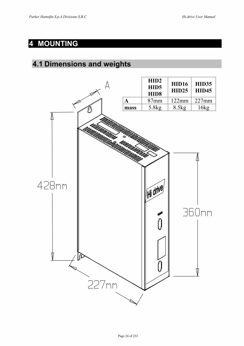
4 MOUNTING
4.1 Dimensions and weights
HID2 HID5 HID8
HID16 HID25
HID35 HID45
A 87mm 122mm 227mm mass 5.8kg 8.5kg 16kg
Parker Hannifin S.p.A Divisione S.B.C Hi-drive User Manual
Page 25 of 233
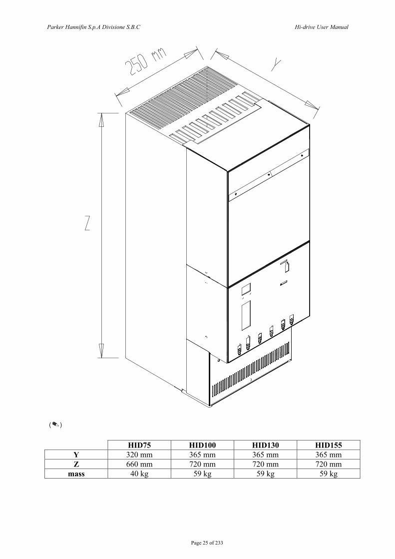
() HID75 HID100 HID130 HID155
Y 320 mm 365 mm 365 mm 365 mm Z 660 mm 720 mm 720 mm 720 mm
mass 40 kg 59 kg 59 kg 59 kg

Parker Hannifin S.p.A Divisione S.B.C Hi-drive User Manual
Page 26 of 233
HID250 A
Z
Y
HID250 A 600 mm Y 465 mm
Z 1145 mm (1500 con BU)
mass 100 kg
(108 kg with brake unit – option)
Parker Hannifin S.p.A Divisione S.B.C Hi-drive User Manual
Page 27 of 233
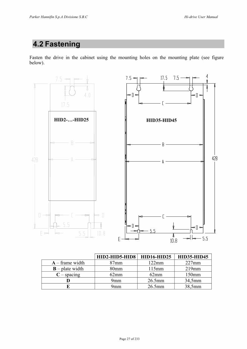
4.2 Fastening Fasten the drive in the cabinet using the mounting holes on the mounting plate (see figure below).
HID2-HID5-HID8 HID16-HID25 HID35-HID45 A – frame width 87mm 122mm 227mm B – plate width 80mm 115mm 219mm
C – spacing 62mm 62mm 150mm D 9mm 26.5mm 34,5mm E 9mm 26.5mm 38,5mm
HID2-…-HID25 HID35-HID45

Parker Hannifin S.p.A Divisione S.B.C Hi-drive User Manual
Page 28 of 233
HID75
HID100-HID130-HID155
Park
er H
anni
fin S
.p.A
Div
isio
ne S
.B.C
Hi-d
rive
Use
r Man
ual
Pa
ge 2
9 of
233
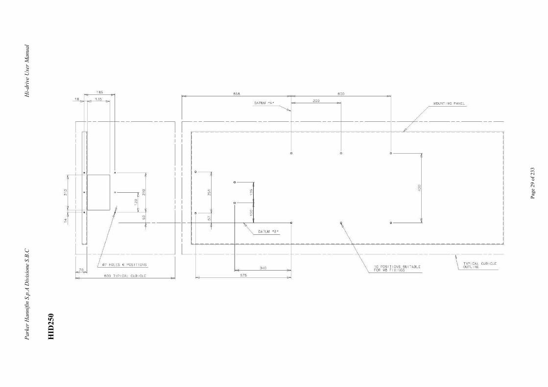
HID
250
N
N
185
18 135
lr - - --t--t- ·-
I
I ,----L-- • r----- · --------.
I
o---r
0 N
'~~~/----:2-j-L __ I __ _ = 6 POSITIONS
0
600 TYPICAL CUBICLE
658 600
300 r...IOUNT I NG PANEL
-------+----- ----·- ____ /'------------------- L ~------------
r II I I
0 -
0 -
"' "' o-,
0 0 0-----.,
I I I I I I I I I I I I I I
0 N o - I
~ I
I II ' , \ o----L :1
' DATUM •s •
I I j
LL~-~~~~~~~~~~~~~~~~~~~
-------------- ----------\----------------------TYPICAL CUBICLE
10 POSITIONS SU I TABL E OUTL INE 340 L__F_OR_M_B_F_I_X_I_NG_S __ _
575
Parker Hannifin S.p.A Divisione S.B.C Hi-drive User Manual
Page 30 of 233
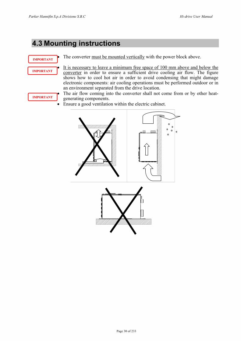
4.3 Mounting instructions
• The converter must be mounted vertically with the power block above. • It is necessary to leave a minimum free space of 100 mm above and below the
converter in order to ensure a sufficient drive cooling air flow. The figure shows how to cool hot air in order to avoid condensing that might damage electronic components: air cooling operations must be performed outdoor or in an environment separated from the drive location.
• The air flow coming into the converter shall not come from or by other heat-generating components.
• Ensure a good ventilation within the electric cabinet.
IIMMPPOORRTTAANNTT
IIMMPPOORRTTAANNTT
IIMMPPOORRTTAANNTT
Parker Hannifin S.p.A Divisione S.B.C Hi-drive User Manual
Page 31 of 233
5 ELECTRICAL CONNECTIONS
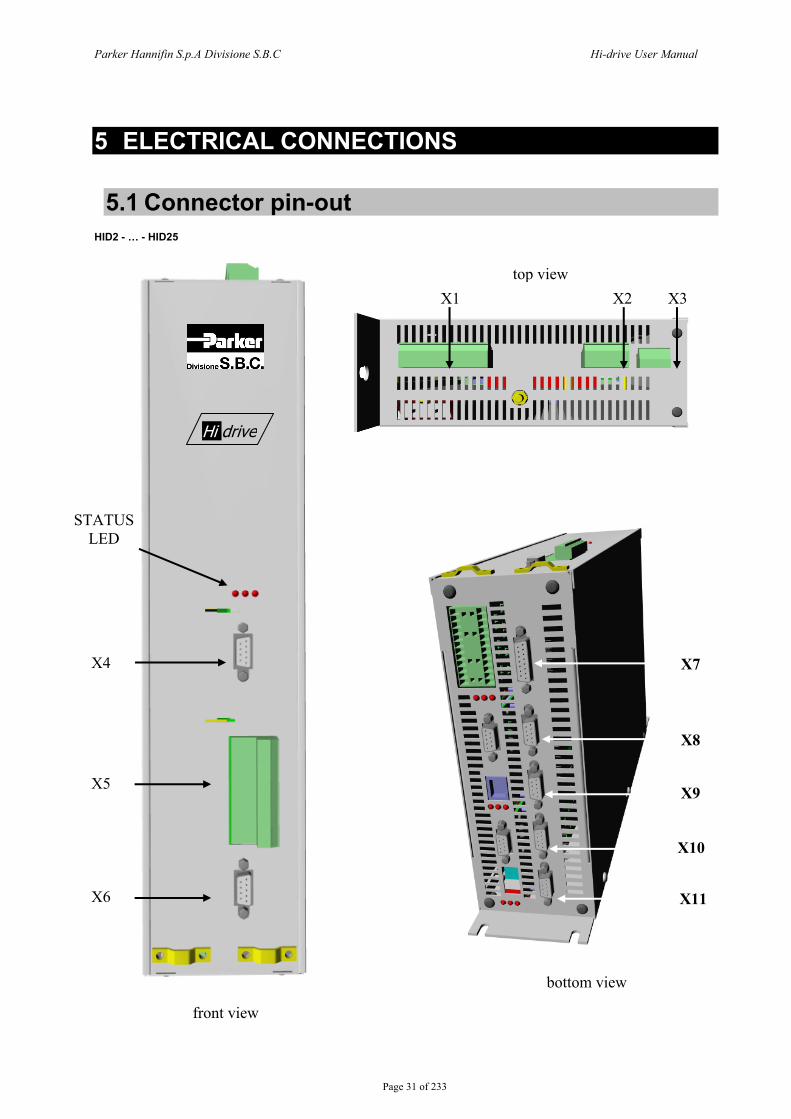
5.1 Connector pin-out HID2 - … - HID25
top view
X11
X10
X9
X8
X7
X1 X2 X3
STATUS LED
X4
X5
X6
Hi drive
bottom view
front view

Parker Hannifin S.p.A Divisione S.B.C Hi-drive User Manual
Page 32 of 233
top panel.
POW
ER S
UPP
LY
MO
TOR
st
atio
nary
B
RA
KE
Xl X 1 1 [!] - 1 0[ + .. 2 -CID -- 2 RP ~ -3 CID - 3 RN ~
4 ~ - 4 IN -5 ~
- 5 BRC .. 6 - 6 L 1 CID .. 7
i===i - 7 L 2 CID --8 ~ - 8 L 3 CID ..
© --- --
X2 X 2 -1 ciiJ .. 1 u '====
'~ -CID - 2 v I~ '==== -CID 3 w I-
~ -I~ - 4 PE -1
r= - 1 +24Vdc BR \'!) -:: 2 @ 2 BR .:: 3 @ -:: 3 BR + 4 @ 4 OVdc BR
'=== -X3 X 3
Parker Hannifin S.p.A Divisione S.B.C Hi-drive User Manual
Page 33 of 233
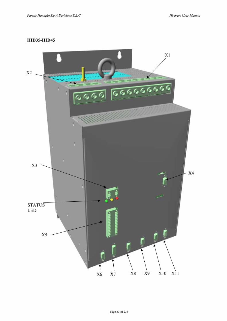
HID35-HID45
X1
X2
X3
X6
X4
X7 X8 X9 X10 X11
STATUS LED
X5
Parker Hannifin S.p.A Divisione S.B.C Hi-drive User Manual
Page 34 of 233
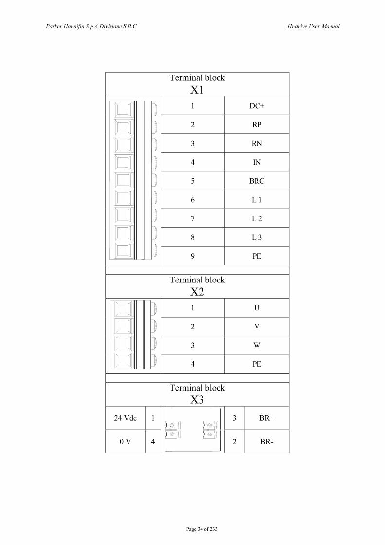
Terminal block
X1
1 DC+
2 RP
3 RN
4 IN
5 BRC
6 L 1
7 L 2
8 L 3
9 PE
Terminal block
X2
1 U
2 V
3 W
4 PE
Terminal block
X3
24 Vdc 1 3 BR+
0 V 4 2 BR-
Parker Hannifin S.p.A Divisione S.B.C Hi-drive User Manual
Page 35 of 233
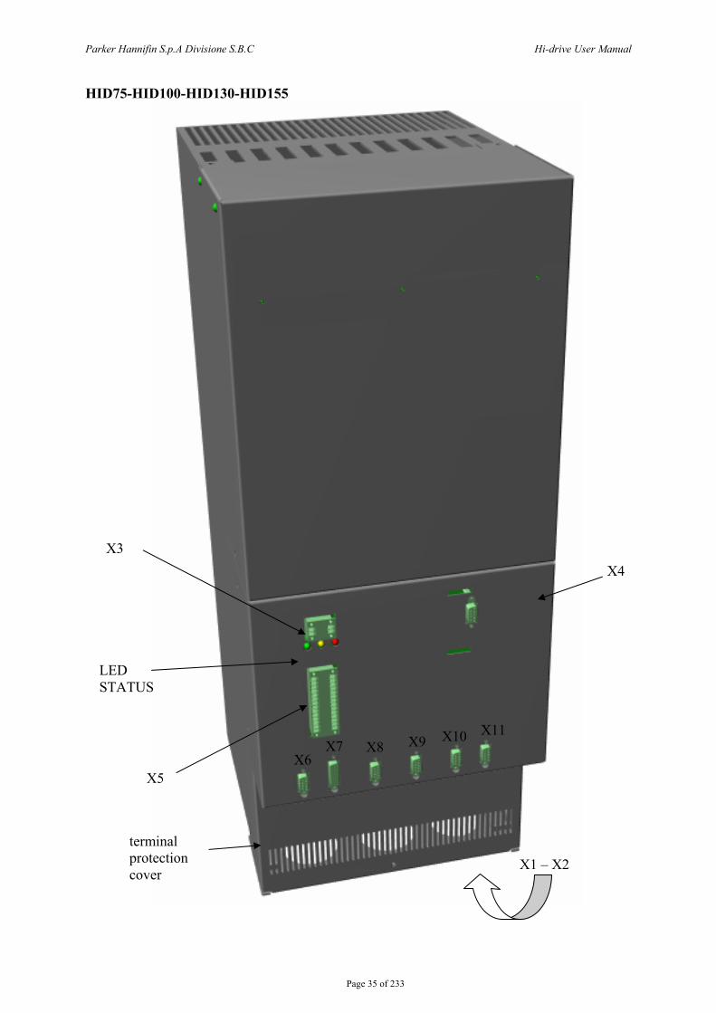
HID75-HID100-HID130-HID155
X8 X9 X10 X11
LED STATUS
X5
X3 X4
X6 X7
X1 – X2 terminal protection cover
Parker Hannifin S.p.A Divisione S.B.C Hi-drive User Manual
Page 36 of 233
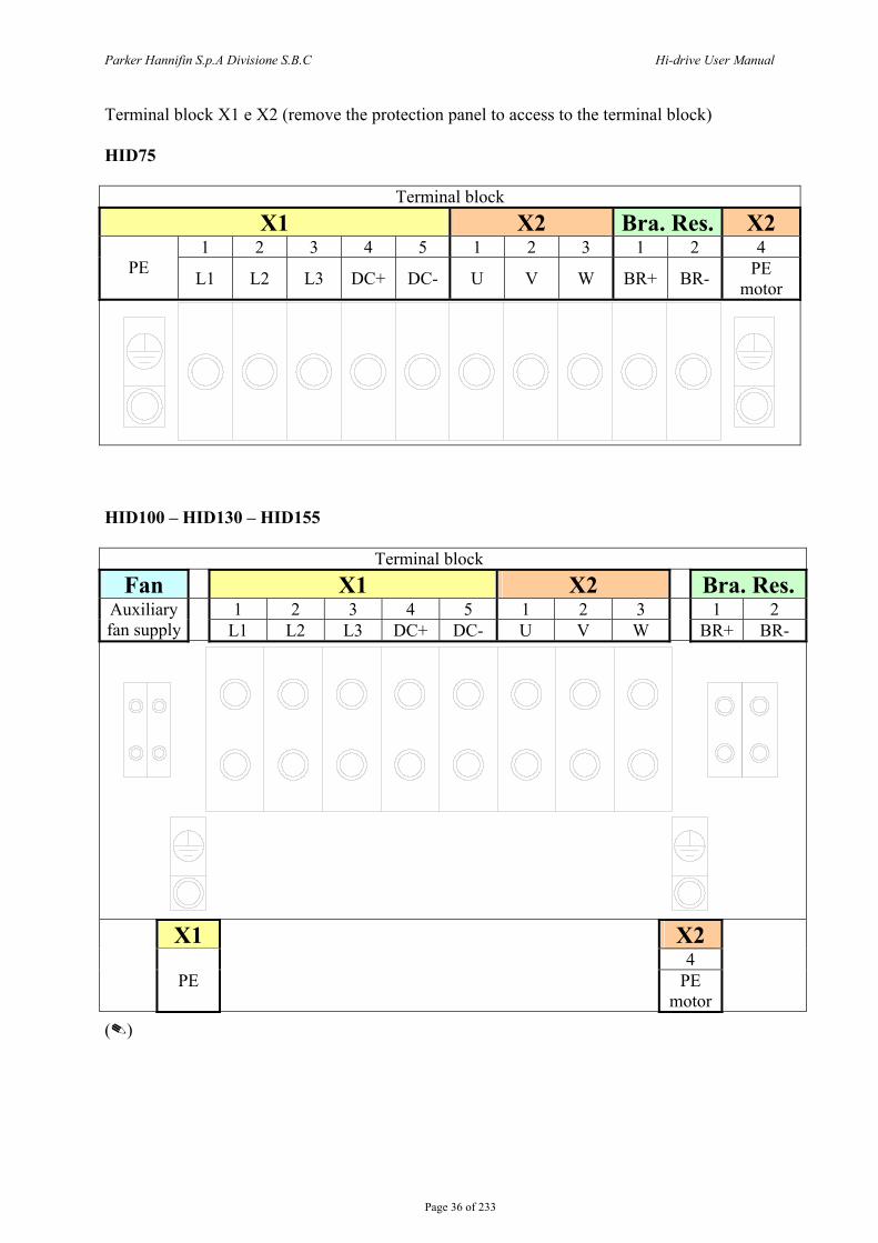
Terminal block X1 e X2 (remove the protection panel to access to the terminal block) HID75 Terminal block
X1 X2 Bra. Res. X2 1 2 3 4 5 1 2 3 1 2 4
PE L1 L2 L3 DC+ DC- U V W BR+ BR- PE motor
HID100 – HID130 – HID155 Terminal block
Fan X1 X2 Bra. Res. 1 2 3 4 5 1 2 3 1 2 Auxiliary
fan supply L1 L2 L3 DC+ DC- U V W BR+ BR-
X1 X2
4
PE
PE motor
()
Parker Hannifin S.p.A Divisione S.B.C Hi-drive User Manual
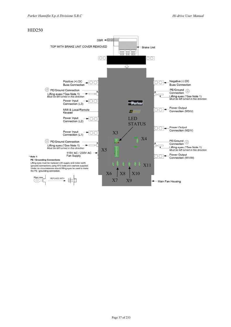
Page 37 of 233
HID250
X8 X9
X10
X11
LED STATUS
X5
X3 X4
X6 X7
Parker Hannifin S.p.A Divisione S.B.C Hi-drive User Manual
Page 38 of 233
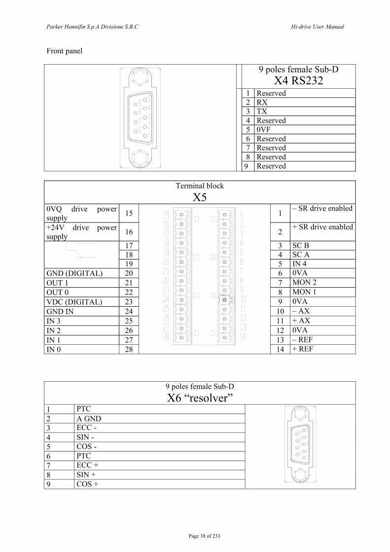
Front panel
9 poles female Sub-D X4 RS232
1 Reserved 2 RX 3 TX 4 Reserved 5 0VF 6 Reserved 7 Reserved 8 Reserved
9 Reserved
Terminal block X5
0VQ drive power supply 15 1 – SR drive enabled
+24V drive power supply 16 2 + SR drive enabled
17 3 SC B 18 4 SC A
19 5 IN 4 GND (DIGITAL) 20 6 0VA OUT 1 21 7 MON 2 OUT 0 22 8 MON 1 VDC (DIGITAL) 23 9 0VA GND IN 24 10 – AX IN 3 25 11 + AX IN 2 26 12 0VA IN 1 27 13 – REF IN 0 28 14 + REF
9 poles female Sub-D X6 “resolver”
1 PTC 2 A GND 3 ECC - 4 SIN - 5 COS - 6 PTC 7 ECC + 8 SIN + 9 COS +
Parker Hannifin S.p.A Divisione S.B.C Hi-drive User Manual
Page 39 of 233
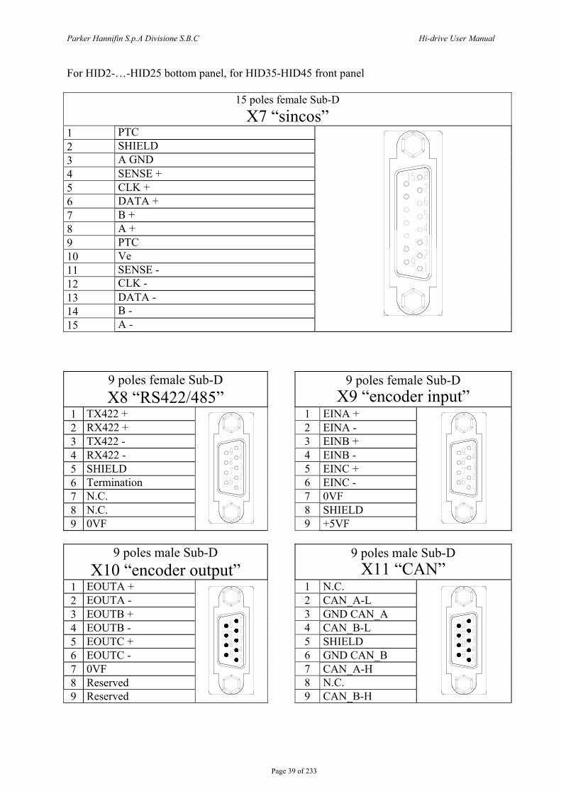
For HID2-…-HID25 bottom panel, for HID35-HID45 front panel
15 poles female Sub-D X7 “sincos”
1 PTC 2 SHIELD 3 A GND 4 SENSE + 5 CLK + 6 DATA + 7 B + 8 A + 9 PTC 10 Ve 11 SENSE - 12 CLK - 13 DATA - 14 B - 15 A -
9 poles female Sub-D X8 “RS422/485”
9 poles female Sub-D X9 “encoder input”
1 TX422 + 1 EINA + 2 RX422 + 2 EINA - 3 TX422 - 3 EINB + 4 RX422 - 4 EINB - 5 SHIELD 5 EINC + 6 Termination 6 EINC - 7 N.C. 7 0VF 8 N.C. 8 SHIELD 9 0VF
9 +5VF
9 poles male Sub-D X10 “encoder output”
9 poles male Sub-D X11 “CAN”
1 EOUTA + 1 N.C. 2 EOUTA - 2 CAN_A-L 3 EOUTB + 3 GND CAN_A 4 EOUTB - 4 CAN_B-L 5 EOUTC + 5 SHIELD 6 EOUTC - 6 GND CAN_B 7 0VF 7 CAN_A-H 8 Reserved 8 N.C. 9 Reserved
9 CAN_B-H
Parker Hannifin S.p.A Divisione S.B.C Hi-drive User Manual
Page 40 of 233
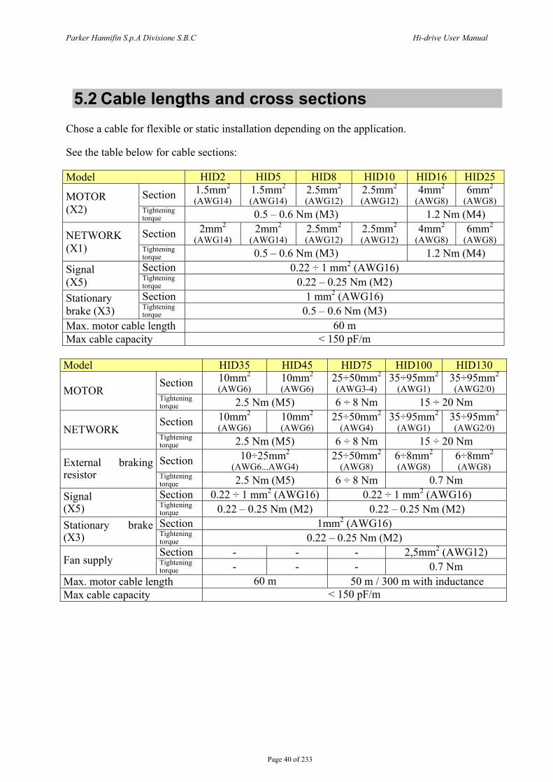
5.2 Cable lengths and cross sections Chose a cable for flexible or static installation depending on the application. See the table below for cable sections: Model HID2 HID5 HID8 HID10 HID16 HID25
Section 1.5mm2 (AWG14)
1.5mm2 (AWG14)
2.5mm2 (AWG12)
2.5mm2 (AWG12)
4mm2 (AWG8)
6mm2 (AWG8) MOTOR
(X2) Tightening torque 0.5 – 0.6 Nm (M3) 1.2 Nm (M4)
Section 2mm2 (AWG14)
2mm2 (AWG14)
2.5mm2 (AWG12)
2.5mm2 (AWG12)
4mm2 (AWG8)
6mm2 (AWG8) NETWORK
(X1) Tightening torque 0.5 – 0.6 Nm (M3) 1.2 Nm (M4) Section 0.22 ÷ 1 mm2 (AWG16) Signal
(X5) Tightening torque 0.22 – 0.25 Nm (M2) Section 1 mm2 (AWG16) Stationary
brake (X3) Tightening torque 0.5 – 0.6 Nm (M3)
Max. motor cable length 60 m Max cable capacity < 150 pF/m Model HID35 HID45 HID75 HID100 HID130
Section 10mm2 (AWG6)
10mm2 (AWG6)
25÷50mm2 (AWG3-4)
35÷95mm2 (AWG1)
35÷95mm2 (AWG2/0) MOTOR
Tightening torque 2.5 Nm (M5) 6 ÷ 8 Nm 15 ÷ 20 Nm
Section 10mm2 (AWG6)
10mm2 (AWG6)
25÷50mm2 (AWG4)
35÷95mm2 (AWG1)
35÷95mm2 (AWG2/0) NETWORK
Tightening torque 2.5 Nm (M5) 6 ÷ 8 Nm 15 ÷ 20 Nm
Section 10÷25mm2 (AWG6...AWG4)
25÷50mm2 (AWG8)
6÷8mm2 (AWG8)
6÷8mm2 (AWG8) External braking
resistor Tightening torque 2.5 Nm (M5) 6 ÷ 8 Nm 0.7 Nm Section 0.22 ÷ 1 mm2 (AWG16) 0.22 ÷ 1 mm2 (AWG16) Signal
(X5) Tightening torque 0.22 – 0.25 Nm (M2) 0.22 – 0.25 Nm (M2) Section 1mm2 (AWG16) Stationary brake
(X3) Tightening torque 0.22 – 0.25 Nm (M2) Section - - - 2,5mm2 (AWG12)
Fan supply Tightening torque - - - 0.7 Nm
Max. motor cable length 60 m 50 m / 300 m with inductance Max cable capacity < 150 pF/m

Parker Hannifin S.p.A Divisione S.B.C Hi-drive User Manual
Page 41 of 233
Model HID155 HID250
Section 35÷95mm2 (AWG1) MOTOR Tightening
torque 15 ÷ 20 Nm 2 holes ø13mm
Separation 44mm Section 35÷95mm2 (AWG1)
NETWORK Tightening torque 15 ÷ 20 Nm
2 holes ø13mm Separation 44mm
Section 6÷8mm2 (AWG8) External braking resistor Tightening
torque 0.7 Nm 2 holes ø13mm
(BU option) Section 0.22 ÷ 1 mm2 (AWG16) Signal
(X5) Tightening torque 0.22 – 0.25 Nm (M2) Section 1mm2 (AWG16) Stationary brake
(X3) Tightening torque 0.22 – 0.25 Nm (M2) Section
Fan supply Tightening torque
2,5mm2 (AWG12) 0.7 Nm
Max. motor cable length 50 m / 300 m with inductance Max cable capacity < 150 pF/m
All signal cables must have a minimum section of 0.22 mm2. The resolver cable must consist of 4 individually shielded twisted pairs protected by a shield. The conductor-conductor capacity for the length used cannot exceed 10 nF and the section cannot be less than 0.22 mm2. The maximum length is 60 m. The motor cable must be shielded. The cables used for analog signals must be shielded twisted pairs. Shielded cables are also recommended for digital inputs and outputs. For UL compliant installations, use only stranded copper wire rated for 75°C. Use only appropriate crimping tools to fix terminal lugs. The conductors capacity shall be 125% of the rated current accordingly to NEC 310-16.

Parker Hannifin S.p.A Divisione S.B.C Hi-drive User Manual
Page 42 of 233
5.3 Protections The drive has no protections against short circuits and overload on the mains side. The user is responsible for short circuit and overload the protection as follows :
Modello HID2
HID 5
HID 8
HID10
HID16
HID25
HID35
HID45
HID 75
HID 100
HID 130
HID 155
HID 250
Fuse size on AC power supply network (delayed) 6A 10A 16A 16A 20A 50A 50A 75A 110A 175A 200A 250A 400AFuse size on VDC control power supply 3.15A fast Fuse size on fan supply - 2A delayed
A thermo-magnetic switch can be used instead of fuses with the same effectiveness, but not in installations with UL standard. For UL compliant installations, use ultra-fast fuses accordingly to UL standard (RC, JFHR2). See the following table:
Model HID2 HID5 HID8-HID10 HID16 HID25
Mains AC (3)
Bussmann FWP10A14F
Ferraz-Shawmut A70P10-1
Bussmann FWP20A14F
Ferraz-Shawmut A70P20-1
Bussmann FWP30A14F
Ferraz-Shawmut A70P30-1
Bussmann FWP-50B
Ferraz-Shawmut A70P50-4
Bussmann FWP-60B
Ferraz-Shawmut A70P60-4
Brake resistor (2)
Bussmann FWP10A14F
Ferraz-Shawmut A70P10-1
Bussmann FWP20A14F
Ferraz-Shawmut A70P20-1
Bussmann FWP20A14F
Ferraz-Shawmut A70P30-1
Bussmann FWP30A14F
Ferraz-Shawmut A70P30-1
Bussmann FWP-35B
Ferraz-Shawmut A70P35-1
DC Bus (2)
Bussmann FWP10A14F
Ferraz-Shawmut A70P10-1
Bussmann FWP20A14F
Ferraz-Shawmut A70P20-1
Bussmann FWP30A14F
Ferraz-Shawmut A70P30-1
Bussmann FWP-50B
Ferraz-Shawmut A70P50-4
Bussmann FWP-60B
Ferraz-Shawmut A70P60-4
Model HID35 HID45 HID75 HID100 HID130
Mains AC (3)
Bussmann FWP-80B
Ferraz-Shawmut A70P80-4
Bussmann FWP-100B
Ferraz-Shawmut A70P100-4
Bussmann FWP125A
Ferraz-Shawmut A70P125-4
Bussmann FWP200A
Ferraz-Shawmut A70P200-4
Bussmann FWP225A
Ferraz-Shawmut A70P225-4
Brake resistor (2)
Bussmann FWP-80B
Ferraz-Shawmut A70P80-4
Bussmann FWP-80B
Ferraz-Shawmut A70P80-1
Bussmann FWP-80B
Ferraz-Shawmut A70P80-4
Bussmann FWP-100B
Ferraz-Shawmut A70P100-4
Bussmann FWP-100B
Ferraz-Shawmut A70P100-4
DC Bus (2)
Bussmann FWP-80B
Ferraz-Shawmut A70P80-4
Bussmann FWP-100B
Ferraz-Shawmut A70P100-4
Bussmann FWP175
Ferraz-Shawmut A70P175-4
Bussmann FWP250
Ferraz-Shawmut A70P250-4
Bussmann FWP300
Ferraz-Shawmut A70P300-4
Parker Hannifin S.p.A Divisione S.B.C Hi-drive User Manual
Page 43 of 233
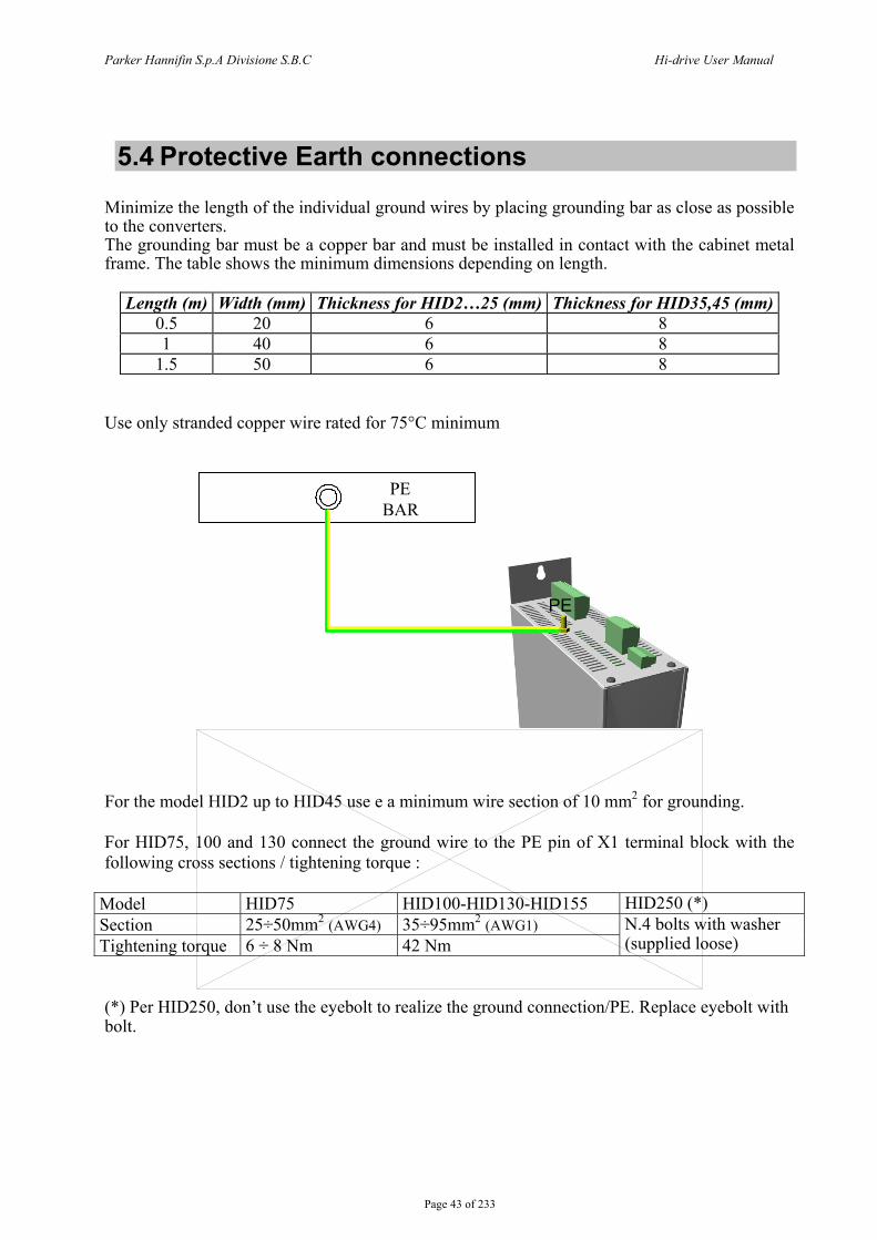
5.4 Protective Earth connections Minimize the length of the individual ground wires by placing grounding bar as close as possible to the converters. The grounding bar must be a copper bar and must be installed in contact with the cabinet metal frame. The table shows the minimum dimensions depending on length.
Length (m) Width (mm) Thickness for HID2…25 (mm) Thickness for HID35,45 (mm)0.5 20 6 8 1 40 6 8
1.5 50 6 8 Use only stranded copper wire rated for 75°C minimum
For the model HID2 up to HID45 use e a minimum wire section of 10 mm2 for grounding. For HID75, 100 and 130 connect the ground wire to the PE pin of X1 terminal block with the following cross sections / tightening torque :
Model HID75 HID100-HID130-HID155 HID250 (*) Section 25÷50mm2 (AWG4) 35÷95mm2 (AWG1) Tightening torque 6 ÷ 8 Nm 42 Nm
N.4 bolts with washer (supplied loose)
(*) Per HID250, don’t use the eyebolt to realize the ground connection/PE. Replace eyebolt with bolt.
PEBAR
PE
Parker Hannifin S.p.A Divisione S.B.C Hi-drive User Manual
Page 44 of 233
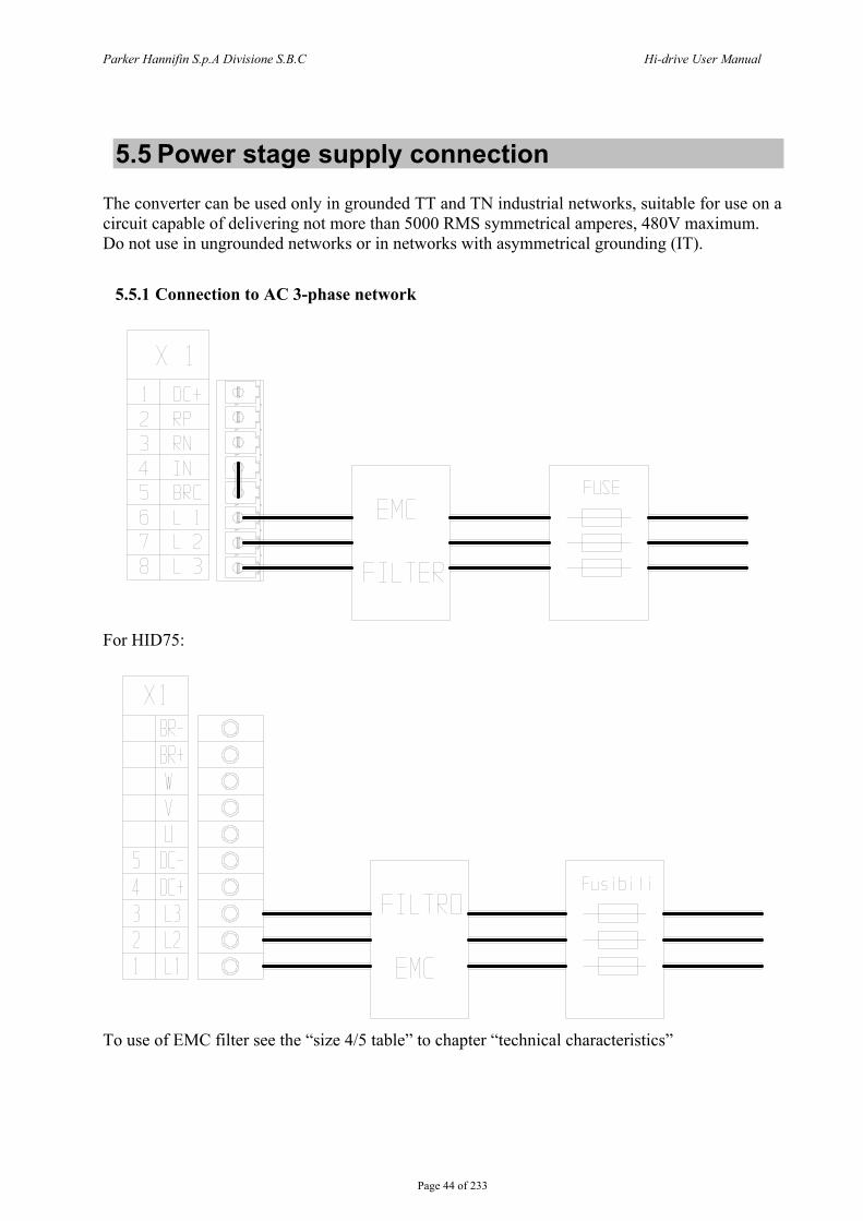
5.5 Power stage supply connection The converter can be used only in grounded TT and TN industrial networks, suitable for use on a circuit capable of delivering not more than 5000 RMS symmetrical amperes, 480V maximum. Do not use in ungrounded networks or in networks with asymmetrical grounding (IT).
5.5.1 Connection to AC 3-phase network
For HID75:
To use of EMC filter see the “size 4/5 table” to chapter “technical characteristics”
Parker Hannifin S.p.A Divisione S.B.C Hi-drive User Manual
Page 45 of 233
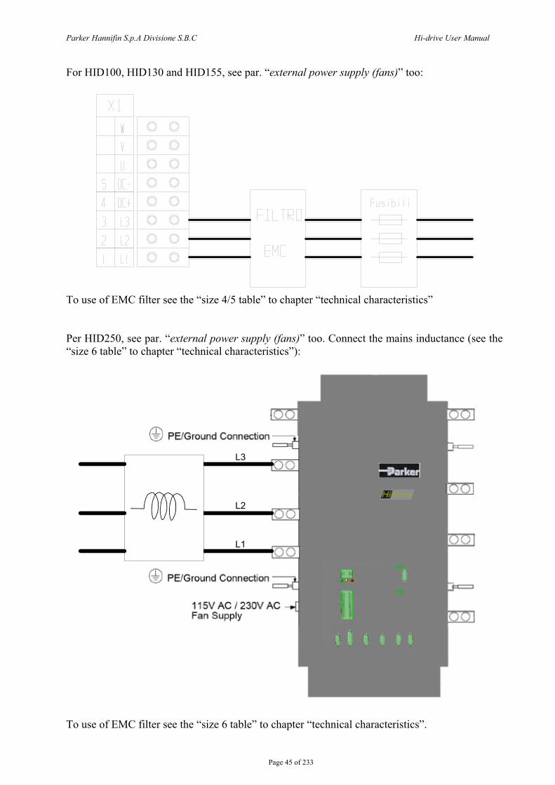
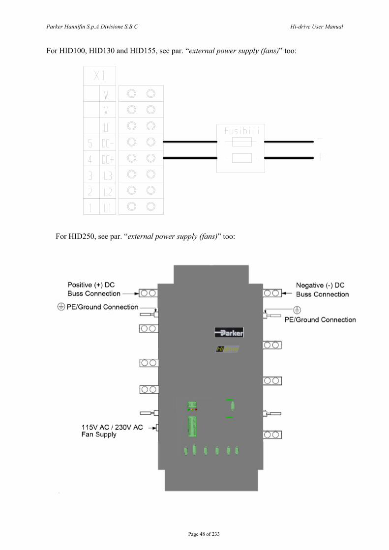
For HID100, HID130 and HID155, see par. “external power supply (fans)” too:
To use of EMC filter see the “size 4/5 table” to chapter “technical characteristics” Per HID250, see par. “external power supply (fans)” too. Connect the mains inductance (see the “size 6 table” to chapter “technical characteristics”):
L1
L2
L3
To use of EMC filter see the “size 6 table” to chapter “technical characteristics”.

Parker Hannifin S.p.A Divisione S.B.C Hi-drive User Manual
Page 46 of 233
5.5.2 Connection to AC 1-phase network
X 1 1 DC+
~ 2 RP 3 RN 4 IN 5 BRC FUSE L 6 L 1 ( Ill EMC EJ 7 L 2 ( I~ EJ 8 L 3 (]J)J FILTER N
Parker Hannifin S.p.A Divisione S.B.C Hi-drive User Manual
Page 47 of 233
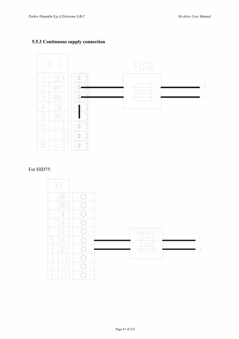
5.5.3 Continuous supply connection
For HID75:
Parker Hannifin S.p.A Divisione S.B.C Hi-drive User Manual
Page 48 of 233
For HID100, HID130 and HID155, see par. “external power supply (fans)” too:
For HID250, see par. “external power supply (fans)” too:

Parker Hannifin S.p.A Divisione S.B.C Hi-drive User Manual
Page 49 of 233
5.6 External Power supply (fans) HID100, HID130, HID155 and HID250 series need an external auxiliary power supply (220V ac), needed for the internal fans. This external supply must be connected to the auxiliary fan terminal block, indicated as “auxiliary supply (fan)”.
Per HID250:
LNE
115V AC/230V ACFan Supply
Parker Hannifin S.p.A Divisione S.B.C Hi-drive User Manual
Page 50 of 233
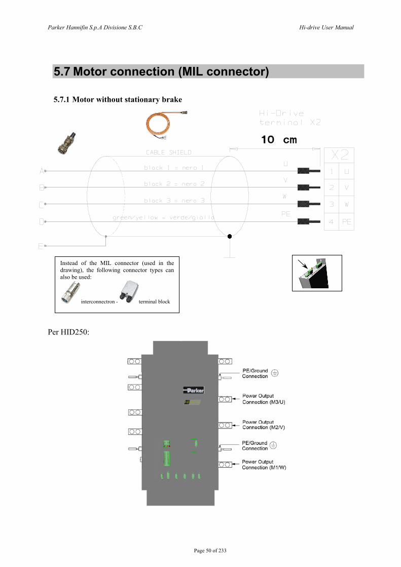
5.7 Motor connection (MIL connector)
5.7.1 Motor without stationary brake
Per HID250:
Instead of the MIL connector (used in the drawing), the following connector types can also be used:
interconnectron - terminal block
Parker Hannifin S.p.A Divisione S.B.C Hi-drive User Manual
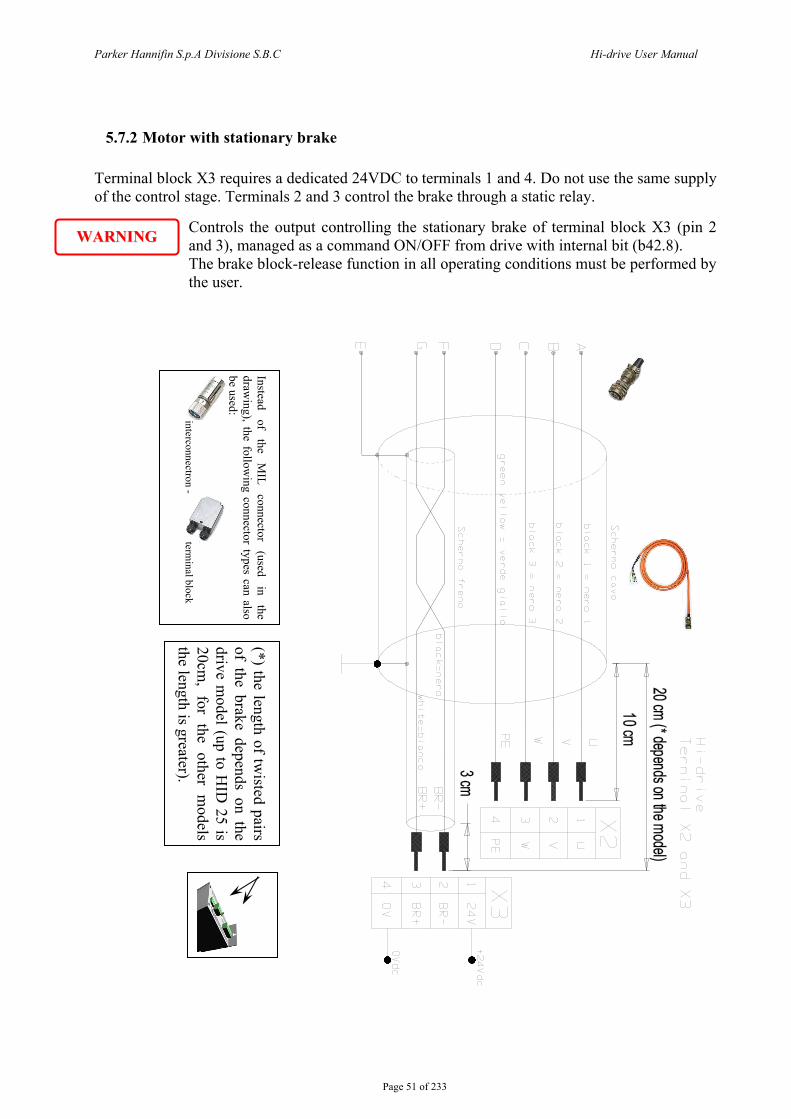
Page 51 of 233
5.7.2 Motor with stationary brake Terminal block X3 requires a dedicated 24VDC to terminals 1 and 4. Do not use the same supply of the control stage. Terminals 2 and 3 control the brake through a static relay.
Controls the output controlling the stationary brake of terminal block X3 (pin 2 and 3), managed as a command ON/OFF from drive with internal bit (b42.8). The brake block-release function in all operating conditions must be performed by the user.
Instead of
the M
IL connector
(used in
the draw
ing), the following connector types can also
be used: interconnectron - term
inal block
WWAARRNNIINNGG
(*) the length of twisted pairs
of the brake depends on the drive m
odel (up to HID
25 is 20cm
, for the other models
the length is greater).

Parker Hannifin S.p.A Divisione S.B.C Hi-drive User Manual
Page 52 of 233
5.8 External braking resistor connection The converter is equipped with internal braking resistor, except HID75, HID100, HID130 and HID155 that have inside the braking transistor only (see “technical data” section). Per HID250 the brake unit (*) is an option. Per the drives equipped of internal braking resistor, an external braking resistor can be used if an higher braking power need to be handled. The external braking resistor must have the same [Ω] value as the internal one. Install a bipolar thermo-magnetic switch (or a fuse pair) between the resistor and the converter (see “dynamic braking” section). The maximum cable length for the external braking resistor is 3 meters. For HID2 … HID45 models, remove the jumper between terminals IN and BRC (X1 terminal block) and connect the external resistor between terminals RP and BRC.
For HID75, HID100, HID130 and HID155 use the “Bra. Res.” terminal block and connect the external braking resistor to BR+ and BR- as follows:
During operation, the external resistor reaches high temperatures. Let the external resistor cool down before performing any operation on it.

Parker Hannifin S.p.A Divisione S.B.C Hi-drive User Manual
Page 53 of 233
(*) BU brake unit for HID250; the external braking resistor must be connected between DC+ bar and DBR bar of the BU module:
The brake unit is optional. However, it is possible to retro-fit a brake unit should the need arise. There are three brake units, one for each drive frame size. The brake units have the following specification:
Operating voltage: 750 - 820Vcc Maximum duty cycle: 30% Maximum on time: 20 seconds Continuous duty: 30% of constant torque drive rating
The original exhaust duct supplied with the drive or the exhaust duct with the brake unit may be used in the final installation. The brake unit consists f the following parts:
− Exhaust duct − Heatsink & IGBT assembly − Control cable − Brake connection plates – 1 set for type 8/9 and 2 sets for type 10 − Heatsink fixings
DBR

Parker Hannifin S.p.A Divisione S.B.C Hi-drive User Manual
Page 54 of 233
− Brake unit cover and retaining nuts − Earth bonding bracket
The brake uniti s shipped in a pre-assembled state (except for the connection plate(s)). It is recommend that this assembly is carefully studied prior to installation within the cubicle. We also recommend that the brake unit heatsink/IGBT assembly is removed from the exhaust duct before installing the unit within the cubicle.
1. Remove the brake unit cover. 2. Remove the earth bonding bracket from the heatsink. 3. Loosen heatsink clamps. 4. Remove the heatsink/IGBT assembly and carefully piace it on a clear flat surface – take
care not to damage the heatsink fins. 5. If retro – fitting the brake unit to an existing exhaust duct then: Remove the exhaust duct
aperture cover and screws. Transfer heatsink clamps and screws from shipping brake duct to existing drive duct.
6. Remove the drive's top front cover (plastic) via 2 off ¼ turn fasteners at top of drive. 7. Remove drive top cover which is attached via 4 off M5 screws on the side and 2 off M5
screws on the top. Care should be taken to prevent the cover from falling into the drive and damaging the internal components. If fitting a new exhaust duct assembly, fit the duct assembly into the top panel and secure to drive with 4 off M5 screws. Secure to the mounting panel with M8 fixings.
8. Install brake unit IGBT/heatsink assembly within exhaust duct and tighten clamps. Take care not to damage components on the PCB with handtools.
9. Connect brake unit control cable to the 14 way bulkhead connector at the top of the drive. 10. Secure the brake connecting plate(s) to the phase joining tabs of the drive top phase
(M3/U) and the phase joining tabs on the brake unit with M5 screws provided. Tighten to 4Nm (3ft/lbs).
11. Fit earth bonding bracket to heatsink and duct connection/earthing screws (M5) to exhaust duct. Tighten to 4Nm (3 ft-lb). Note – This connection must not be omitted a sit is required for safety reasons.
12. Replace drive top cover, exercise care to not damage brake connection plates with the top cover as this will compromise the electrical insulation. Tighten 4 off M5 screws on side of drive and 2 off M5 screws on top of cover to 2.5 Nm (1.84 ft-lb).
13. Replace drive front top cover with 2 off ¼ turn fasteners. 14. Fit brake unit cover with M6 captive washer nuts.
Parker Hannifin S.p.A Divisione S.B.C Hi-drive User Manual
Page 55 of 233
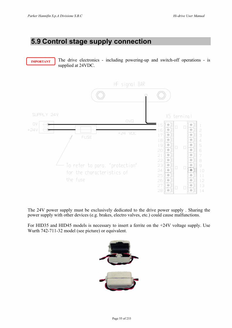
5.9 Control stage supply connection
The drive electronics - including powering-up and switch-off operations - is supplied at 24VDC.
The 24V power supply must be exclusively dedicated to the drive power supply . Sharing the power supply with other devices (e.g. brakes, electro valves, etc.) could cause malfunctions. For HID35 and HID45 models is necessary to insert a ferrite on the +24V voltage supply. Use Wurth 742-711-32 model (see picture) or equivalent.
IIMMPPOORRTTAANNTT
Parker Hannifin S.p.A D
ivisione S.B.C
H
i-drive User M
anual
Page 56 of 233
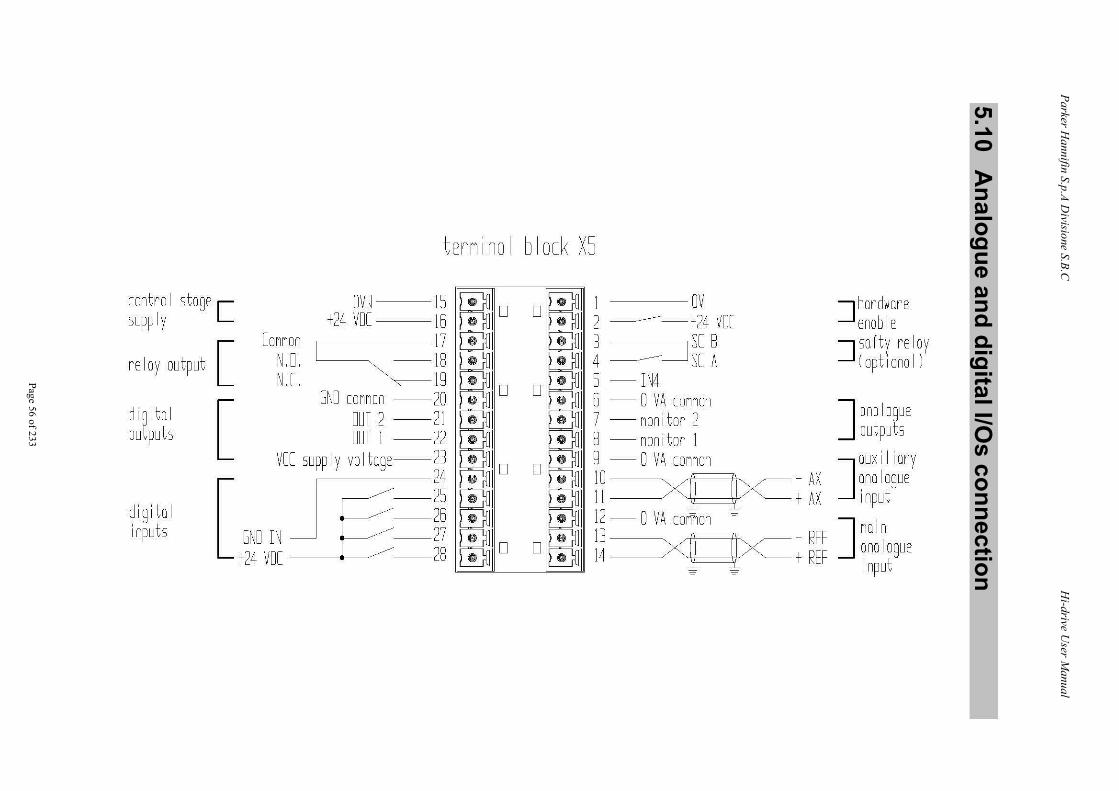
5.10 A
nalogue and digital I/Os connection
tErninol block XS
control stage [ supply
re lay output [::
digital outputs [
Connon N.D. N.C.
OVQ --15 +24 VDC 16
,----------17
~-:~
digi tal inputs
GND connon --20 OUT 2 - 21 OUT 1 - 22
VCC supp I y vo I toge--23 24
[ GI<U IN I l~ +24 VDC -28
1 ov 2 ---------- t 24 VDC
J ---------~ ~f ~ S - IN4 6 - 0 VA connon 7 - nonitor 2 8 - nonitor 1 9 - 0 VA connon 10 ~~ 11-~
12 - 0 VA contion -13 1 4 -~
~hardware enab le
~ so fty reI oy (opt i ono I )
J ana Iogue outputs
J ouxi I iory
- AX onologue t AX input
_ REF J no 1n t REF ?nologue
1nput

Parker Hannifin S.p.A Divisione S.B.C Hi-drive User Manual
Page 57 of 233
Main analog input: Number 1 Range ±10V differential Input resistance 8.61kΩ ±5% Resolution 14 bit + sign Maximum frequency 2 kHz
Auxiliary analog input Number 1 Range ±10V differential Input resistance 8.61kΩ ±5% Resolution 10 bit Maximum frequency 800 Hz
Digital inputs Number 5 opto isolated High voltage range 15 ÷ 24V Low voltage range 0 ÷9V Input resistance 20kΩ±5% Reaction time =2.5μs Type of driving required PNP
Analog outputs Number 2 Range ±10V Output resistance 1kΩ Resolution 10 bit + sign Max. output current 1.5mA Short circuit protection Yes Overload protection Yes
Digital outputs Number 2 opto isolated Type PNP open collectorExternal digital power supply 5 ÷24Vdc
Rise time =200μs VH Vpower – 1.0 V VL -0.5 ÷ 1.5V Max. output current 100mA Short-circuit protection Yes Overload protection Yes
Relay output Number 1 (NO - NC) Voltage 24V Max current 1A
ANALOG OUTPUT
DIGITAL INPUT
DIGITAL OUTPUT
ANALOG INPUT
Voltage supply

Parker Hannifin S.p.A Divisione S.B.C Hi-drive User Manual
Page 58 of 233
5.11 Feedback connection
5.11.1 Resolver
When the resolver is connected, no incremental encoders can be used on connector X7.
Instead of the MIL connector (used in the drawing), the following connector types can also be used:
interconnectron - terminal block
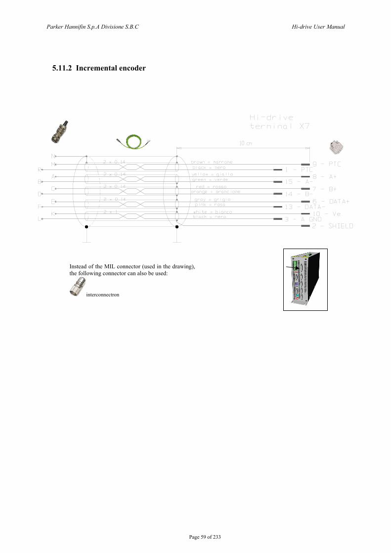
Parker Hannifin S.p.A Divisione S.B.C Hi-drive User Manual
Page 59 of 233
5.11.2 Incremental encoder
Instead of the MIL connector (used in the drawing), the following connector can also be used:
interconnectron
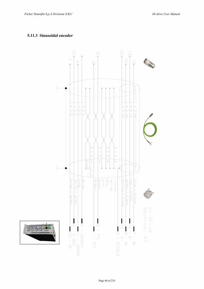
Parker Hannifin S.p.A Divisione S.B.C Hi-drive User Manual
Page 60 of 233
5.11.3 Sinusoidal encoder
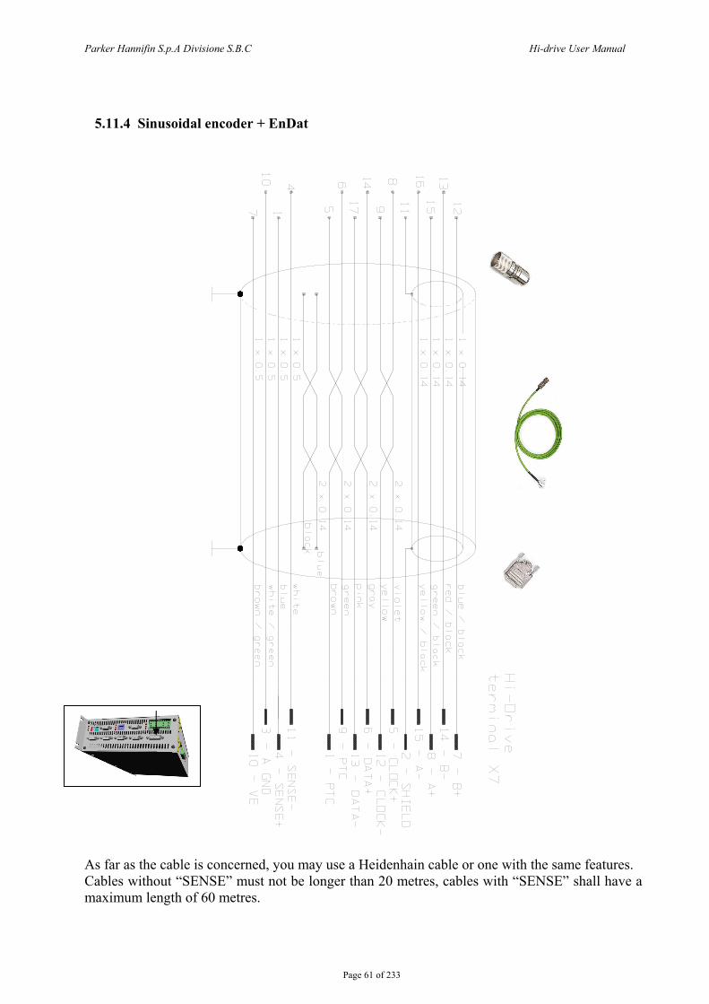
Parker Hannifin S.p.A Divisione S.B.C Hi-drive User Manual
Page 61 of 233
5.11.4 Sinusoidal encoder + EnDat
As far as the cable is concerned, you may use a Heidenhain cable or one with the same features. Cables without “SENSE” must not be longer than 20 metres, cables with “SENSE” shall have a maximum length of 60 metres.
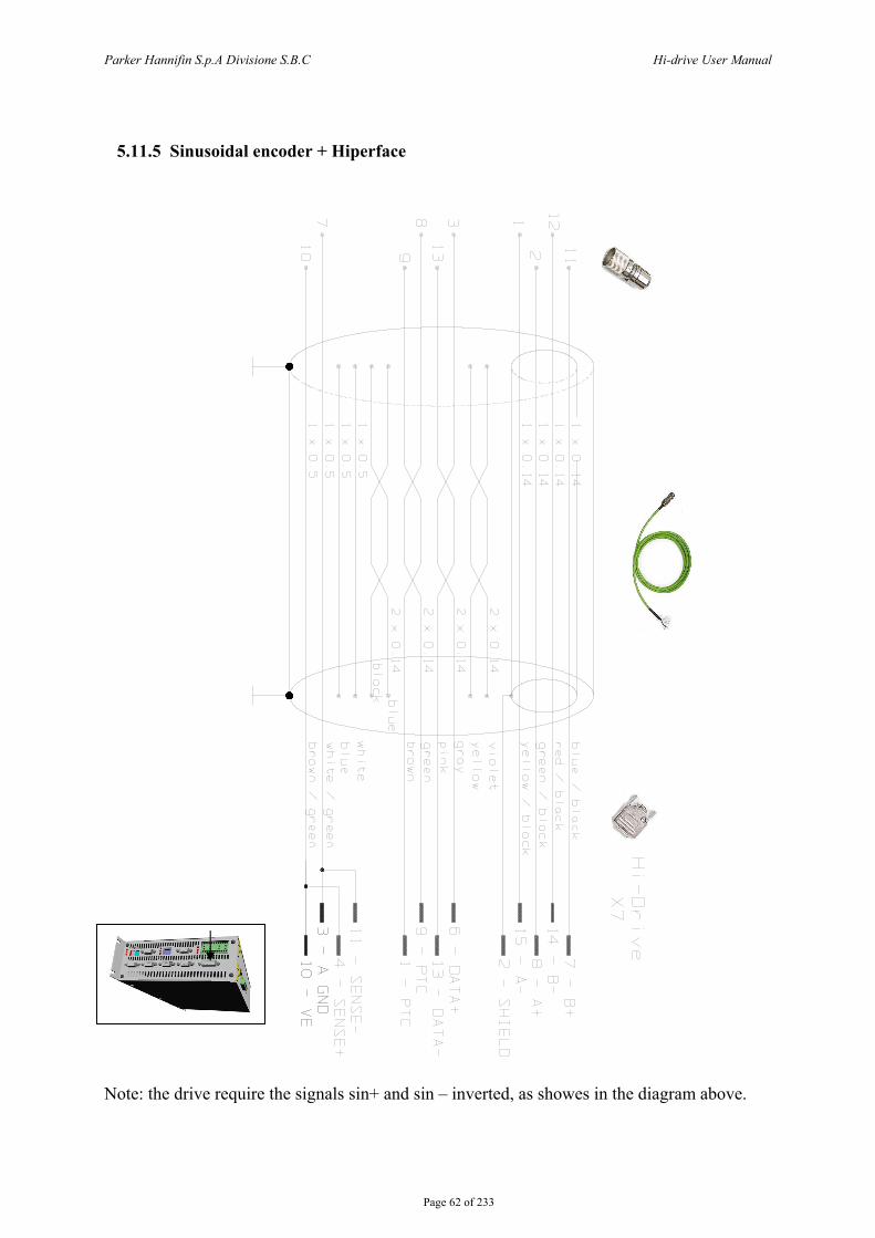
Parker Hannifin S.p.A Divisione S.B.C Hi-drive User Manual
Page 62 of 233
5.11.5 Sinusoidal encoder + Hiperface
Note: the drive require the signals sin+ and sin – inverted, as showes in the diagram above.
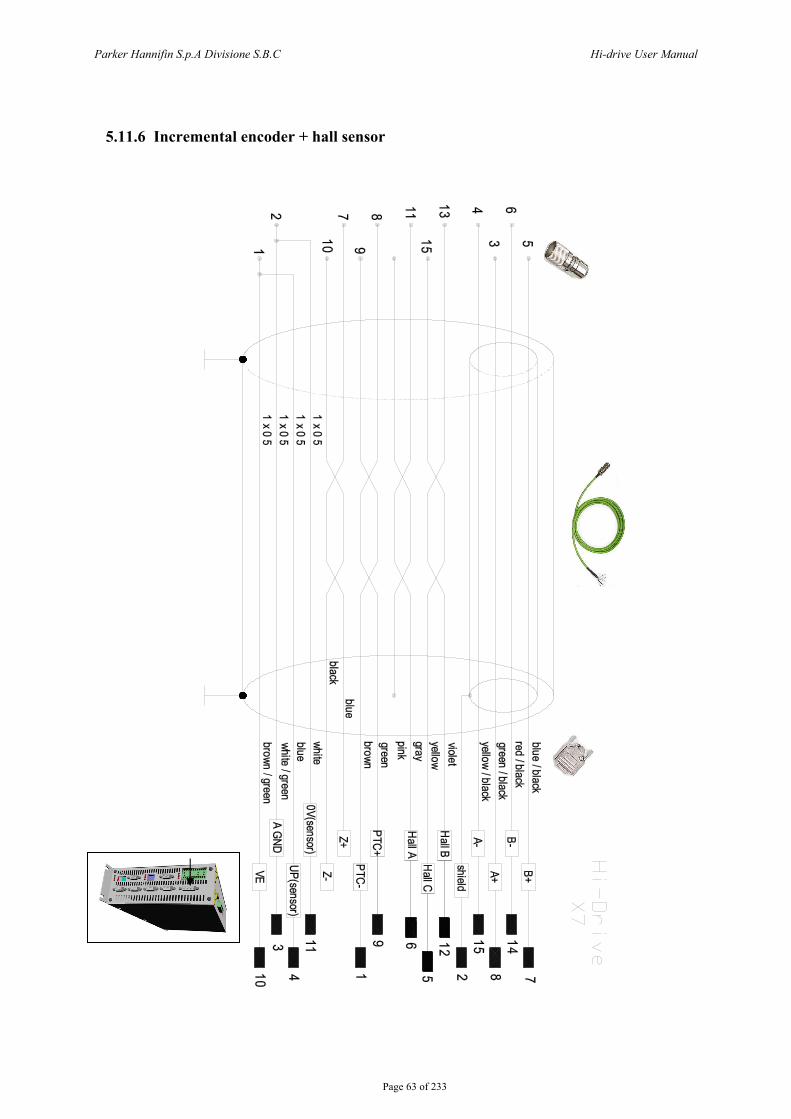
Parker Hannifin S.p.A Divisione S.B.C Hi-drive User Manual
Page 63 of 233
5.11.6 Incremental encoder + hall sensor
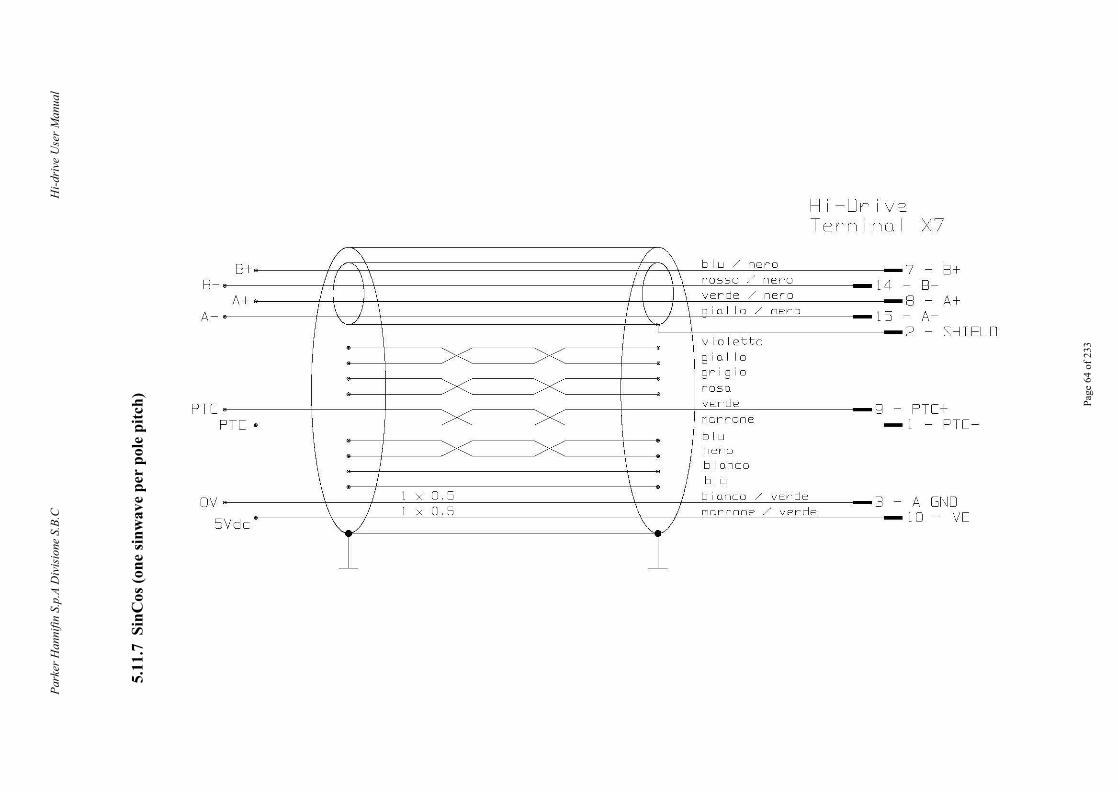
Park
er H
anni
fin S
.p.A
Div
isio
ne S
.B.C
Hi-d
rive
Use
r Man
ual
Pa
ge 6
4 of
233
5.11
.7 S
inC
os (o
ne si
nwav
e pe
r po
le p
itch)
~~ I 8+- ~ b l u /nero
Hi - Dr i ve Tern i no l X7
7 - 8 + 8 -
8 - 8 - A+ If \ \ I \ \ rosso / ner o 14 I I )_l I I \ verde / ne r o A+ I \ ) j / \ _g i o l lo/ A-
A- 2 - SH IELD ne r o 15 / ./ \
v i o letto g i o I lo g r i g i o rosa verde g -narron e PT[
PTC+ PT C l - PTC-
b lu \ nero
\ \ b i anco
I \ I b lu
I 1 X 0 5 \ b i anco/ verde 3 -\ I 1 X 0 . 5 I norrone / ve r de
Vdc \_/ \J
1 1 A G~~O
OV 10 - VE 5
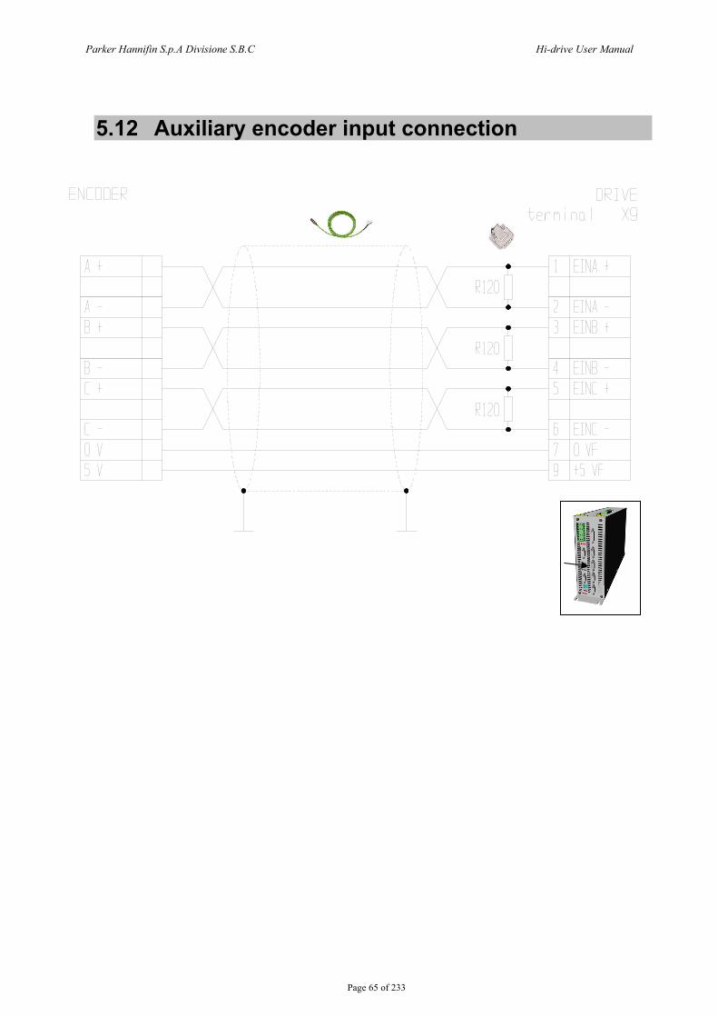
Parker Hannifin S.p.A Divisione S.B.C Hi-drive User Manual
Page 65 of 233
5.12 Auxiliary encoder input connection
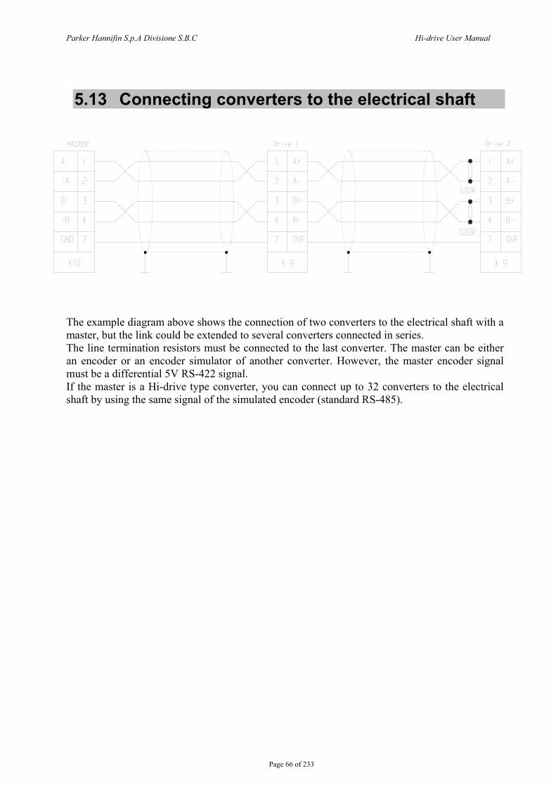
Parker Hannifin S.p.A Divisione S.B.C Hi-drive User Manual
Page 66 of 233
5.13 Connecting converters to the electrical shaft
The example diagram above shows the connection of two converters to the electrical shaft with a master, but the link could be extended to several converters connected in series. The line termination resistors must be connected to the last converter. The master can be either an encoder or an encoder simulator of another converter. However, the master encoder signal must be a differential 5V RS-422 signal. If the master is a Hi-drive type converter, you can connect up to 32 converters to the electrical shaft by using the same signal of the simulated encoder (standard RS-485).
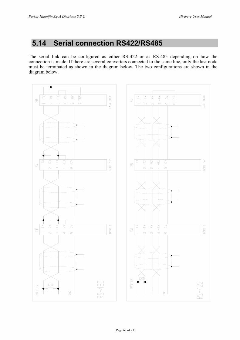
Parker Hannifin S.p.A Divisione S.B.C Hi-drive User Manual
Page 67 of 233
5.14 Serial connection RS422/RS485 The serial link can be configured as either RS-422 or as RS-485 depending on how the connection is made. If there are several converters connected to the same line, only the last node must be terminated as shown in the diagram below. The two configurations are shown in the diagram below.
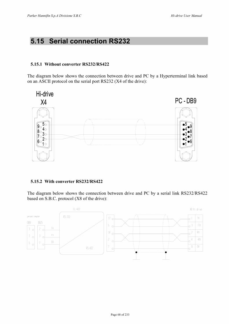
Parker Hannifin S.p.A Divisione S.B.C Hi-drive User Manual
Page 68 of 233
5.15 Serial connection RS232
5.15.1 Without converter RS232/RS422 The diagram below shows the connection between drive and PC by a Hyperterminal link based on an ASCII protocol on the serial port RS232 (X4 of the drive):
5.15.2 With converter RS232/RS422
The diagram below shows the connection between drive and PC by a serial link RS232/RS422 based on S.B.C. protocol (X8 of the drive):
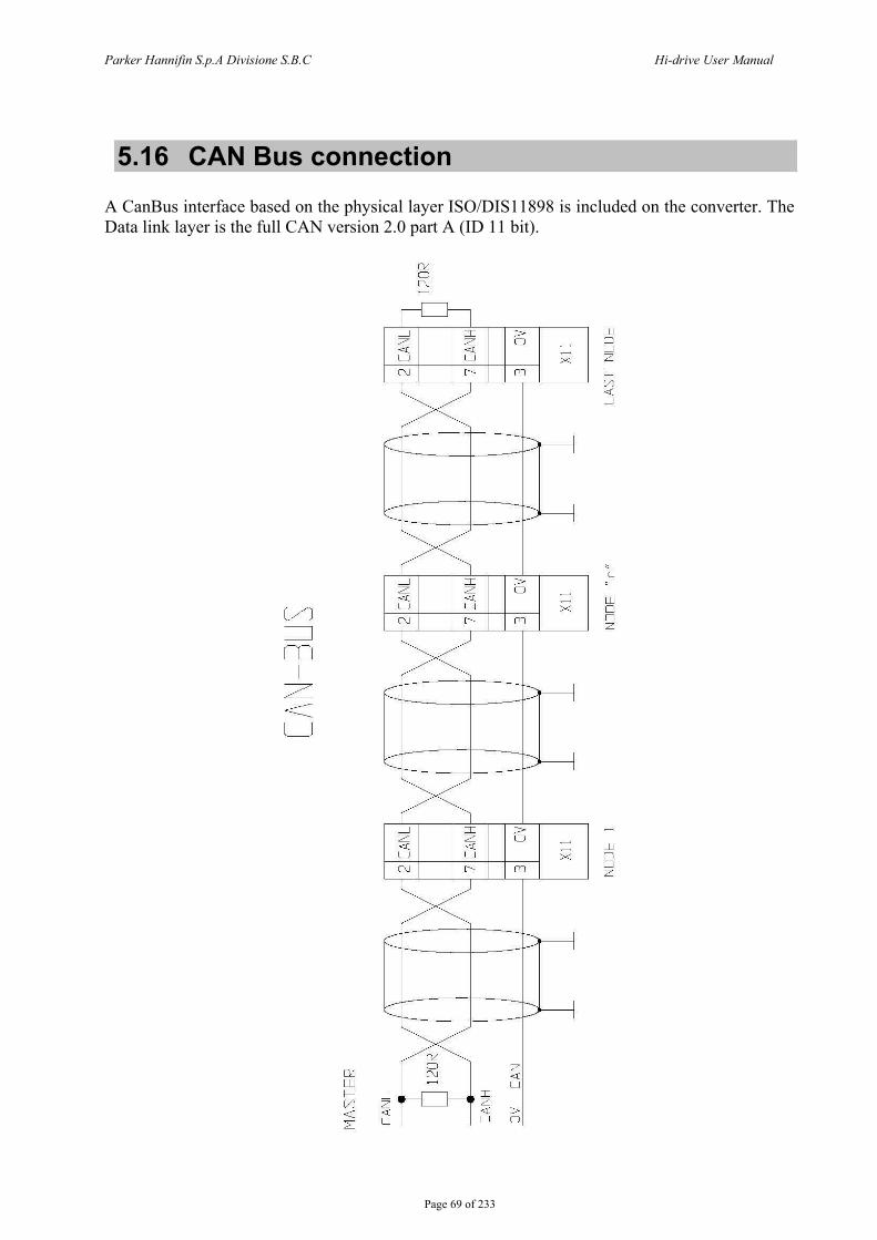
Parker Hannifin S.p.A Divisione S.B.C Hi-drive User Manual
Page 69 of 233
5.16 CAN Bus connection A CanBus interface based on the physical layer ISO/DIS11898 is included on the converter. The Data link layer is the full CAN version 2.0 part A (ID 11 bit).
(/)
= co I
<( l_j
Ck w f-Vl <(
2:
OL 0 (\J
~ _j I z: z: <( <(
u u ('J ['--.
X r:=::
v-'-----
X _j I z: z: <( <( u u ('J ['--.
X ,...--1'--t--
~r-'....__
X _j I z: z: <( <(
u u ('J ['--.
X r:=::
v-'-----
OL 0 (\J -
_j ~ z <[
u
> 0
~ -X
"'
~r--------1
~L----1
> 0
~ -X
"'
-H--------1
->------1
> 0
~ -X rrl
~>--------1
~>--------1
z <[
u I z <[ > u 0
w D D z
-c
w D D z
w D D z
Parker Hannifin S.p.A Divisione S.B.C Hi-drive User Manual
Page 70 of 233
5.17 Electro-magnetic compliance In order to meet the requirements of EMC product standards (EN61800-3), the drive must be installed in strict compliance with the instructions below. Because of strong PWM voltage fronts caused by the converter, high capacitive currents can sometimes circulate through couplings in the grounding systems (conductive noise). High frequency disturbances are also possible, especially from motor cables, in the form of radiated emissions. Radiated and conductive disturbances can be reduced or prevented through:
grounding, shielding filtering, so as to reduce both the conductive interference in the cables and the return
conductive interference to the source (frequency converter) by using paths with the lowest possible impedance. In this way other systems connected to the same electrical line are protected effectively and the frequency converter will also be protected from the interference of other systems.
5.17.1 Grounding Two different grounding systems are used in the electric cabinets where the converters are usually installed:
- The EMC grounding, or HF (high frequency) reference, which is the uncoated metal surface where drives and filters are installed.
- The safety or PE (protective earth) grounding according to EN60204-1.
Install converter, network filter, 24V power supply etc. on the metal surface so as to ensure the maximum possible electric contact (HF connection) between the zinc-coated steel sheet and the converter’s (rear) mounting plate.

Parker Hannifin S.p.A Divisione S.B.C Hi-drive User Manual
Page 71 of 233
5.17.2 Connection cables and shielding Except the mains-filter cables, all other power and control cables must be shielded and kept separated (min. distance between cables 20 cm). Where control cables must cross power cables make sure they are at an angle as near 90° as possible. Shielded cable screens shall be free and grounded on a copper bar by means of a connection provided with cable gland (360º connection) as shown in the drawing, in order to ensure an appropriate conductivity. The motor cables and the power cables can never run parallel.
Connection 360°
Usually the screen is connected on both ends. In some cases, however, the control cable screen (resolver, encoder, I/O, low voltage power supply, serial link) may be connected only on one end when the current in the screen causes noises to the shielded cable signal. The input cable must be connected to the PE grounding by means of a screw connection so as to ensure a proper contact between the screen and the grounding. The power section (converter) and the control section (PLC or CN) must be kept separated by a division in the metal base. Connect the panels in the electric cabinet by means of a copper strap. Never route noise-emitting cables in parallel with “clean” cables Never route cables in parallel, especially near the filter (ensure sufficient distance) Never route cables in loops (cables should be kept as short as possible and be close to the common potential). It is particularly important to keep mains cables away from motor cables. If the motor is provided with emergency braking, keep the brake connection and power cables away from the other cables (resolver and signal).
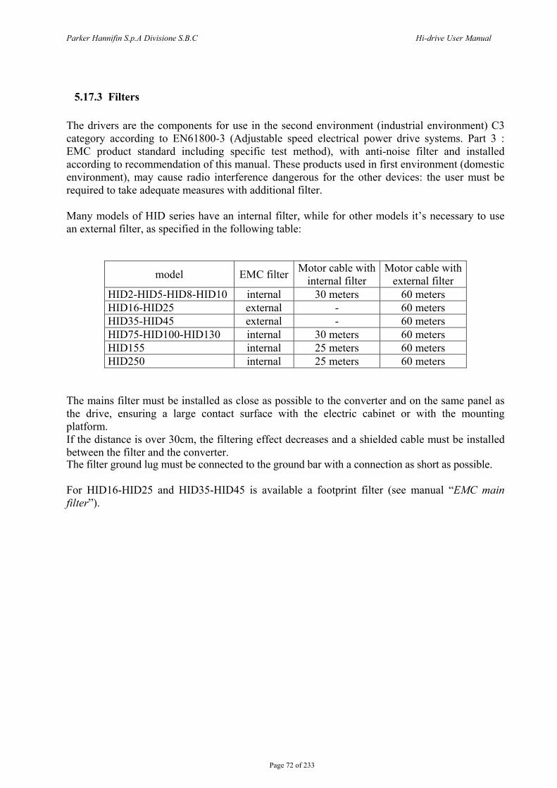
Parker Hannifin S.p.A Divisione S.B.C Hi-drive User Manual
Page 72 of 233
5.17.3 Filters The drivers are the components for use in the second environment (industrial environment) C3 category according to EN61800-3 (Adjustable speed electrical power drive systems. Part 3 : EMC product standard including specific test method), with anti-noise filter and installed according to recommendation of this manual. These products used in first environment (domestic environment), may cause radio interference dangerous for the other devices: the user must be required to take adequate measures with additional filter. Many models of HID series have an internal filter, while for other models it’s necessary to use an external filter, as specified in the following table:
model EMC filter Motor cable with internal filter
Motor cable with external filter
HID2-HID5-HID8-HID10 internal 30 meters 60 meters HID16-HID25 external - 60 meters HID35-HID45 external - 60 meters HID75-HID100-HID130 internal 30 meters 60 meters HID155 internal 25 meters 60 meters HID250 internal 25 meters 60 meters
The mains filter must be installed as close as possible to the converter and on the same panel as the drive, ensuring a large contact surface with the electric cabinet or with the mounting platform. If the distance is over 30cm, the filtering effect decreases and a shielded cable must be installed between the filter and the converter. The filter ground lug must be connected to the ground bar with a connection as short as possible. For HID16-HID25 and HID35-HID45 is available a footprint filter (see manual “EMC main filter”).

Parker Hannifin S.p.A Divisione S.B.C Hi-drive User Manual
Page 73 of 233
5.18 Cabling general layout The following drawing show the details of the cabling layout, with particular attention to the grounding of shielded cables. The electric cabinet bottom must be electrically conductive , e.g. zinc-coated. Strip off any paint coat to ensure contact. The grounding bar must be in contact with the cabinet bottom or ensure an excellent electric connection and it must NOT be insulated. Route power cables away from signal cables. The 24V input power cable must be shielded as well.
*Install the PE (Protective Earthing) grounding bar together with the HF bar o in order to prevent contact with the zinc-coating bottom. Connect the two bars as shown in the diagram. **Signal cables can be grounded either by means of a separate (HF) bar or directly connecting the (metal) cable glands to the cabinet bottom (in this latter case, ensure that the PE bar is in contact with the cabinet zinc-coated bottom). ***The above diagram is to be considered as an overall view.
Hi drive
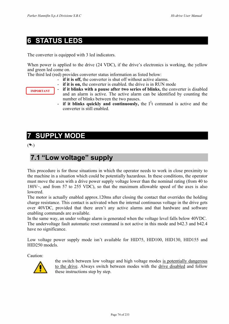
Parker Hannifin S.p.A Divisione S.B.C Hi-drive User Manual
Page 74 of 233
6 STATUS LEDS The converter is equipped with 3 led indicators. When power is applied to the drive (24 VDC), if the drive’s electronics is working, the yellow and green led come on. The third led (red) provides converter status information as listed below:
- if it is off, the converter is shut off without active alarms. - if it is on, the converter is enabled. the drive is in RUN mode - if it blinks with a pause after two series of blinks, the converter is disabled
and an alarm is active. The active alarm can be identified by counting the number of blinks between the two pauses.
- if it blinks quickly and continuously, the I2t command is active and the converter is still enabled.
7 SUPPLY MODE ()
7.1 “Low voltage” supply This procedure is for those situations in which the operator needs to work in close proximity to the machine in a situation which could be potentially hazardous. In these conditions, the operator must move the axes with a drive power supply voltage lower than the nominal rating (from 40 to 180V~, and from 57 to 255 VDC), so that the maximum allowable speed of the axes is also lowered. The motor is actually enabled approx.120ms after closing the contact that overrides the holding charge resistance. This contact is activated when the internal continuous voltage in the drive gets over 40VDC, provided that there aren’t any active alarms and that hardware and software enabling commands are available. In the same way, an under voltage alarm is generated when the voltage level falls below 40VDC. The undervoltage fault automatic reset command is not active in this mode and b42.3 and b42.4 have no significance. Low voltage power supply mode isn’t available for HID75, HID100, HID130, HID155 and HID250 models. Caution:
the switch between low voltage and high voltage modes is potentially dangerous to the drive. Always switch between modes with the drive disabled and follow these instructions step by step.
IIMMPPOORRTTAANNTT
Parker Hannifin S.p.A Divisione S.B.C Hi-drive User Manual
Page 75 of 233
o Low voltage to nominal operating voltage sequence.
a. Disable the drive. Wait 200ms. b. Change the voltage from low to nominal. c. Set bit b40.10 to 0 d. Wait 1.2s. e. Enable the drive.
o Nominal operating voltage to low voltage sequence. a. Disable the drive. b. Set bit b40.10 to 1 c. Change the voltage from nominal to low. d. Wait 200ms. e. Enable the drive. The drive will be enabled after about 1.12s.
7.2 “High voltage” supply In “high ” voltage operating mode (b40.0=0), the converter can supplied as follows:
- AC 3-phase network (200…480 ±10%) Set b39.0=0 (default). The converter can automatically detect the power supply voltage rating and adapts internal operating parameters accordingly. When the mains voltage is >440VAC, b41.13=1 and output current is de. When one of the power supply phases is missing, b42.4=1.
- AC 1-phase network (200…277 ±10%) Set b39.0=1 and set the peak nominal value of 1-phase supply (√2*Vphase-neutral) in Pr21. Save, switch off and on again the converter.
With both modes of AC power supply, when parameter b42.3=0 the input power supply is on. In case of power loss the bit is set to one, anticipating the converter’s “under voltage” alarm that is based on continuous voltage.
- Continuous (288…678 ±10%) Set b39.0=1 and set the nominal value of continuous voltage in Pr21 . Save, switch off and on again the converter.
The automatic reset of “under voltage” undervoltage alarm can be forced by b39.8=1 with any kind of power supply.

Parker Hannifin S.p.A Divisione S.B.C Hi-drive User Manual
Page 76 of 233
8 START-UP In Its basic configuration, Hi-drive can control both synchronous permanent magnet motors (brushless) and asynchronous induction motors. The setting of Pr31 can select either of the following:
- Pr31=0 synchronous motor (default setting) - Pr31=1 asynchronous motor
The drive is supplied with default factory parameter settings. See the following chapters for use and start-up.
8.1 Setting the default parameters When you carry out a default procedure, all factory parameters are changed and any previously entered value is lost. In order to carry out the procedure, go through the steps below:
- supply 24VDC power to the drive (X5 pin 15 and 16); - disable drive hardware b41.5=0; - set the pico-PLC in stop, b39.13=0; - command b42.12=1, in order to load the default parameters; - save the data by commands b42.14 and b42.15 (the drive must be disabled); - Save, switch off and on again the drive.
8.2 Selection of motor type The first time the converter is powered up, or following a default command, the drive indicates a “Def” condition (alarm Pr23=15). In order to leave the drive’s initial condition, the operator shall have to input the motor data. The parameters defining motor types are as follows:
Pr29 Number of motor poles N. Pr32 rated motor speed r.p.m. Pr33 rated motor current (ex. 2.5A, write 2.5) A Pr46 phase-phase motor resistance (ex. 1,8Ω, write 1.8) ohm Pr47 phase-phase motor inductance (ex. 2.6mH, write 2.6) mH Pr60 number of resolver poles N.
With asynchronous motors, the values above shall be supplemented with the following parameters:
Pr45 base speed r.p.m. Pr48 slip r.p.m. Pr49 magnetizing current A Pr32 motor limit speed r.p.m.
After setting the parameters that identify the motor, the operator shall enter a data save command, b42.15 (with drive disabled, b41.5=0). The drive will set the values of parameters Pr2, Pr3, Pr16, Pr17, Pr18 and Pr19 through its internal logic. The automatic calculation of the above listed parameters is performed only of the drive is in the default condition (alarm 15).
Only asynchronous motors
Parker Hannifin S.p.A Divisione S.B.C Hi-drive User Manual
Page 77 of 233
8.3 Changing motor data After having entered a data save command, no other changes shall be made to the motor parameters . In order to change the entered parameter values (new motor), enter command b42.1. The drive shall return to its default condition and changing motor data shall be enabled again. Repeat the data save procedure with command b42.15 (with drive disabled) if you want to recalculate parameters Pr2, Pr3, Pr16, Pr17, Pr18 and Pr19 with the new motor data.
8.4 Setting feedback A key feature of Hi-drive is the ability to cope with several types of feedback, that can be used simultaneously both as speed feedback and as position feedback, depending on the connection and on parameter settings. Speed and position feedback connections use three different connectors:
1. A feedback, connection on input X6. 2. B feedback, connection on input X7. 3. C feedback, connection on input X9.
8.4.1 A feedback, input X6. Input X6 can be used to link:
Resolver The input is dedicated to resolver read only. When this input is used, it must be identified as speed feedback. In case of a space operating mode, the resolver can be also used as space feedback.
8.4.2 B feedback, input X7. Input X7 can be used to link:
Encoder sincos + EnDat interface Encoder sincos Encoder less wiring Line drive incremental encoder RS422
Signal RS422 on this port does not require the line to be closed by resistors, as these are already present inside. When the resolver is connected to port X6, do not connect Less Wiring encoder and incremental encoder to port X7.
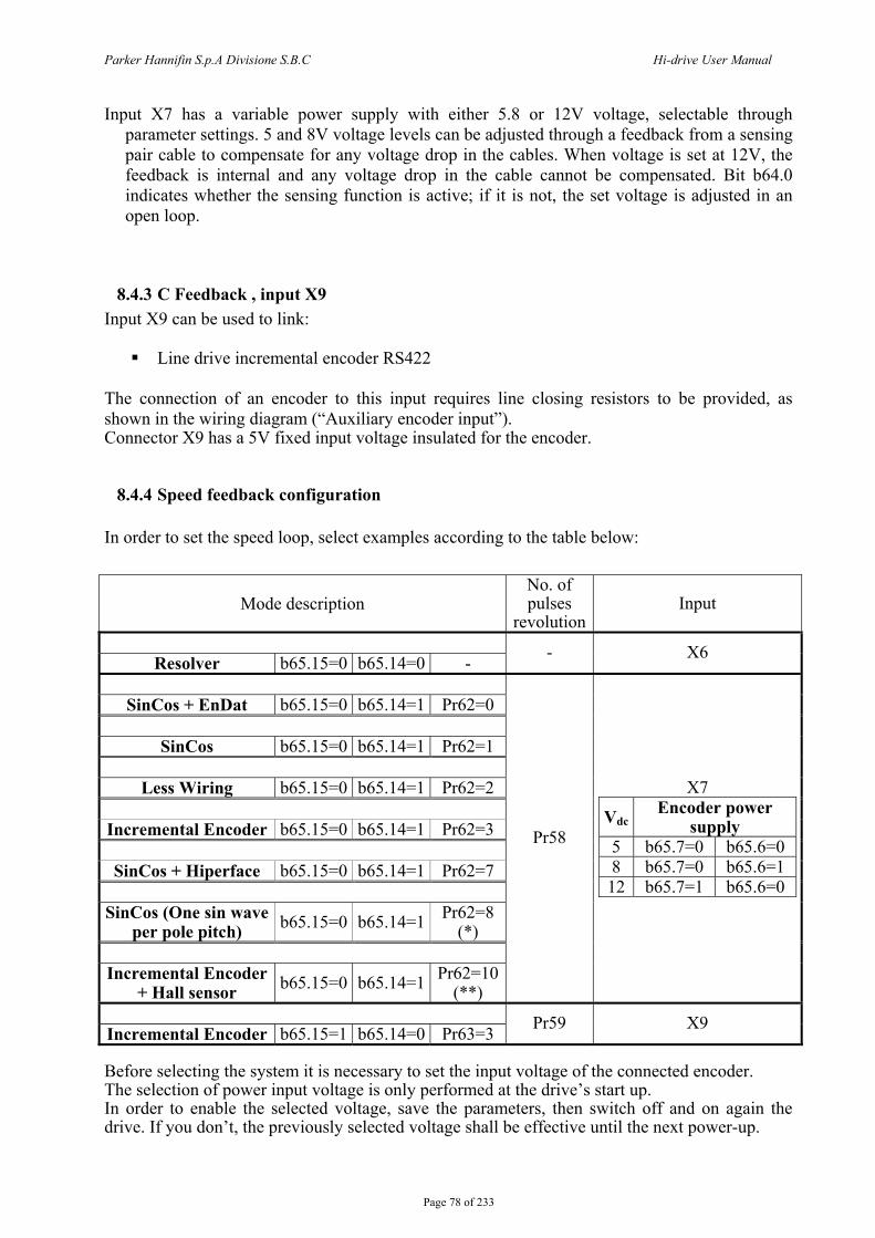
Parker Hannifin S.p.A Divisione S.B.C Hi-drive User Manual
Page 78 of 233
Input X7 has a variable power supply with either 5.8 or 12V voltage, selectable through parameter settings. 5 and 8V voltage levels can be adjusted through a feedback from a sensing pair cable to compensate for any voltage drop in the cables. When voltage is set at 12V, the feedback is internal and any voltage drop in the cable cannot be compensated. Bit b64.0 indicates whether the sensing function is active; if it is not, the set voltage is adjusted in an open loop.
8.4.3 C Feedback , input X9 Input X9 can be used to link:
Line drive incremental encoder RS422 The connection of an encoder to this input requires line closing resistors to be provided, as shown in the wiring diagram (“Auxiliary encoder input”). Connector X9 has a 5V fixed input voltage insulated for the encoder.
8.4.4 Speed feedback configuration In order to set the speed loop, select examples according to the table below:
Mode description No. of pulses
revolutionInput
Resolver b65.15=0 b65.14=0 - - X6
SinCos + EnDat b65.15=0 b65.14=1 Pr62=0
SinCos b65.15=0 b65.14=1 Pr62=1
Less Wiring b65.15=0 b65.14=1 Pr62=2
Incremental Encoder b65.15=0 b65.14=1 Pr62=3
SinCos + Hiperface b65.15=0 b65.14=1 Pr62=7
SinCos (One sin wave
per pole pitch) b65.15=0 b65.14=1 Pr62=8 (*)
Incremental Encoder
+ Hall sensor b65.15=0 b65.14=1 Pr62=10(**)
Pr58
X7
Vdc Encoder power
supply 5 b65.7=0 b65.6=0 8 b65.7=0 b65.6=1 12 b65.7=1 b65.6=0
Incremental Encoder b65.15=1 b65.14=0 Pr63=3 Pr59 X9
Before selecting the system it is necessary to set the input voltage of the connected encoder. The selection of power input voltage is only performed at the drive’s start up. In order to enable the selected voltage, save the parameters, then switch off and on again the drive. If you don’t, the previously selected voltage shall be effective until the next power-up.
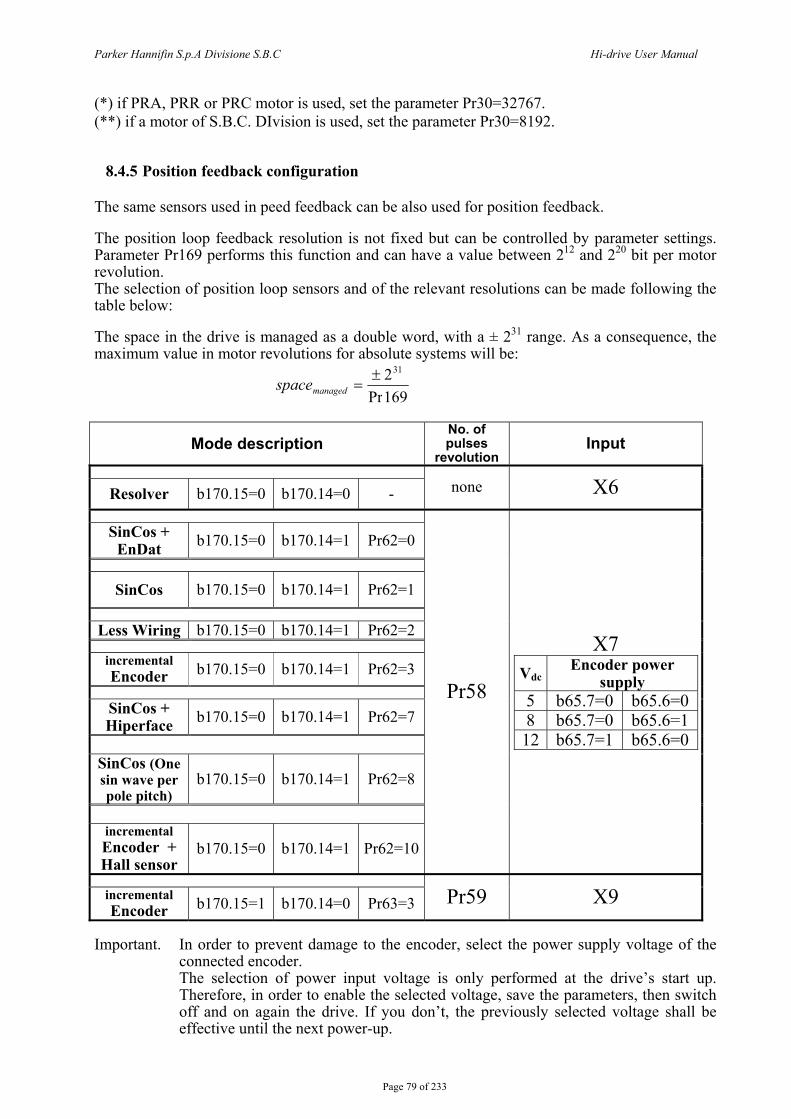
Parker Hannifin S.p.A Divisione S.B.C Hi-drive User Manual
Page 79 of 233
(*) if PRA, PRR or PRC motor is used, set the parameter Pr30=32767. (**) if a motor of S.B.C. DIvision is used, set the parameter Pr30=8192.
8.4.5 Position feedback configuration The same sensors used in peed feedback can be also used for position feedback. The position loop feedback resolution is not fixed but can be controlled by parameter settings. Parameter Pr169 performs this function and can have a value between 212 and 220 bit per motor revolution. The selection of position loop sensors and of the relevant resolutions can be made following the table below: The space in the drive is managed as a double word, with a ± 231 range. As a consequence, the maximum value in motor revolutions for absolute systems will be:
169Pr231±
=managedspace
Mode description No. of pulses
revolution Input
Resolver b170.15=0 b170.14=0 - none X6
SinCos + EnDat b170.15=0 b170.14=1 Pr62=0
SinCos b170.15=0 b170.14=1 Pr62=1
Less Wiring b170.15=0 b170.14=1 Pr62=2
incremental Encoder b170.15=0 b170.14=1 Pr62=3
SinCos + Hiperface b170.15=0 b170.14=1 Pr62=7
SinCos (One sin wave per pole pitch)
b170.15=0 b170.14=1 Pr62=8
incremental Encoder + Hall sensor
b170.15=0 b170.14=1 Pr62=10
Pr58
X7 Vdc
Encoder power supply
5 b65.7=0 b65.6=0 8 b65.7=0 b65.6=1
12 b65.7=1 b65.6=0
incremental Encoder b170.15=1 b170.14=0 Pr63=3 Pr59 X9
Important. In order to prevent damage to the encoder, select the power supply voltage of the
connected encoder. The selection of power input voltage is only performed at the drive’s start up. Therefore, in order to enable the selected voltage, save the parameters, then switch off and on again the drive. If you don’t, the previously selected voltage shall be effective until the next power-up.

Parker Hannifin S.p.A Divisione S.B.C Hi-drive User Manual
Page 80 of 233
()
8.4.6 Digital filter per encoder Using bit b65.8, b65.9 and b65.10, if is necessary, it’s possible to generate a digital filter to “clean” the encoder signal, connected to the X7 feedback input. While using bit b65.11, b65.12 and b65.13, it’s generated a digital filter for the auxiliary encoder. The table below shows the filters characteristics. Pay attention to motor speed in according to the max frequency filtered, to not limit the motor speed.
Binary code b65.10 b65.9 b65.8 b65.13 b65.12 b65.11
Minimum pulse time[nsec]
Max frequency [kHz]
0 0 0 642.5 778 0 0 1 1142.5 437 0 1 0 1642.5 304 0 1 1 2142.5 233 1 0 0 2642.5 189 1 0 1 3142.5 159 1 1 0 3642.5 137 1 1 1 4142.5 120
8.5 Phasing procedure Phasing is necessary when the speed loop feedback is via incremental encoder incremental or SinCos, as these encoders do not provide the absolute positioning on the motor shaft. Phasing must be performed any time the drive is powered up. The incremental encoder phasing does not allow to use the encoder simulator zero trace to set the external control axis to zero, since the drive encoder simulation is not provided with a fixed mechanical position in the motor revolution, but this is initialized any time a phasing command is given. During the incremental encoder operations the motor must be halted. If this type of feedback is performed on the vertical axis, the phasing operations will be allowed only if the system is balanced, that is if the vertical axis can be stopped without braking. Before proceeding, consider that two phasing procedures are available, both requiring that the motor can rotate even if it is installed inside the equipment (any emergency brake disabled). Note that, in the first type of phasing procedure, the requested motor movement is larger then in type 2 phasing. In type 1 procedure a cabling test is performed This procedure is therefore recommended during the system’s fine-tuning.
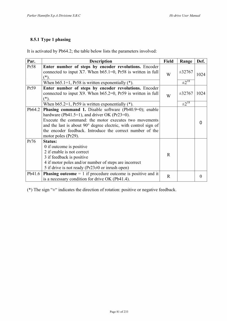
Parker Hannifin S.p.A Divisione S.B.C Hi-drive User Manual
Page 81 of 233
8.5.1 Type 1 phasing It is activated by Pb64.2; the table below lists the parameters involved: Par. Description Field Range Def.
Enter number of steps by encoder revolutions. Encoder connected to input X7. When b65.1=0, Pr58 is written in full (*).
±32767Pr58
When b65.1=1, Pr58 is written exponentially (*).
W
±218
1024
Enter number of steps by encoder revolutions. Encoder connected to input X9. When b65.2=0, Pr59 is written in full (*).
±32767 1024Pr59
When b65.2=1, Pr59 is written exponentially (*).
W
±218 Pb64.2 Phasing command 1. Disable software (Pb40.9=0); enable
hardware (Pb41.5=1), and driver OK (Pr23=0). Execute the command: the motor executes two movements and the last is about 90° degree electric, with control sign of the encoder feedback. Introduce the correct number of the motor poles (Pr29).
0
Pr76 Status: 0 if outcome is positive 2 if enable is not correct 3 if feedback is positive 4 if motor poles and/or number of steps are incorrect 5 if drive is not ready (Pr23≠0 or inrush open)
R
Pb41.6 Phasing outcome = 1 if procedure outcome is positive and it is a necessary condition for drive OK (Pb41.4). R 0
(*) The sign “±“ indicates the direction of rotation: positive or negative feedback.
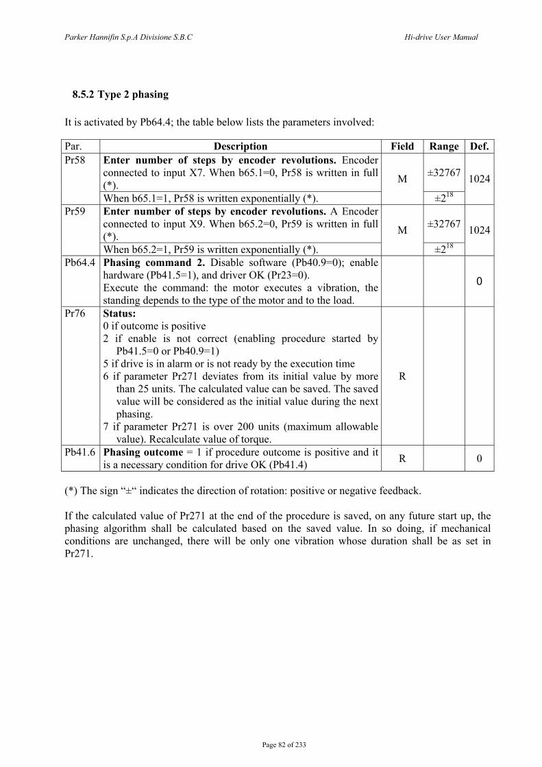
Parker Hannifin S.p.A Divisione S.B.C Hi-drive User Manual
Page 82 of 233
8.5.2 Type 2 phasing It is activated by Pb64.4; the table below lists the parameters involved: Par. Description Field Range Def.
Enter number of steps by encoder revolutions. Encoder connected to input X7. When b65.1=0, Pr58 is written in full (*).
±32767Pr58
When b65.1=1, Pr58 is written exponentially (*).
M
±218
1024
Enter number of steps by encoder revolutions. A Encoder connected to input X9. When b65.2=0, Pr59 is written in full (*).
±32767Pr59
When b65.2=1, Pr59 is written exponentially (*).
M
±218
1024
Pb64.4 Phasing command 2. Disable software (Pb40.9=0); enable hardware (Pb41.5=1), and driver OK (Pr23=0). Execute the command: the motor executes a vibration, the standing depends to the type of the motor and to the load.
0
Pr76 Status: 0 if outcome is positive 2 if enable is not correct (enabling procedure started by
Pb41.5=0 or Pb40.9=1) 5 if drive is in alarm or is not ready by the execution time 6 if parameter Pr271 deviates from its initial value by more
than 25 units. The calculated value can be saved. The saved value will be considered as the initial value during the next phasing.
7 if parameter Pr271 is over 200 units (maximum allowable value). Recalculate value of torque.
R
Pb41.6 Phasing outcome = 1 if procedure outcome is positive and it is a necessary condition for drive OK (Pb41.4) R 0
(*) The sign “±“ indicates the direction of rotation: positive or negative feedback. If the calculated value of Pr271 at the end of the procedure is saved, on any future start up, the phasing algorithm shall be calculated based on the saved value. In so doing, if mechanical conditions are unchanged, there will be only one vibration whose duration shall be as set in Pr271.
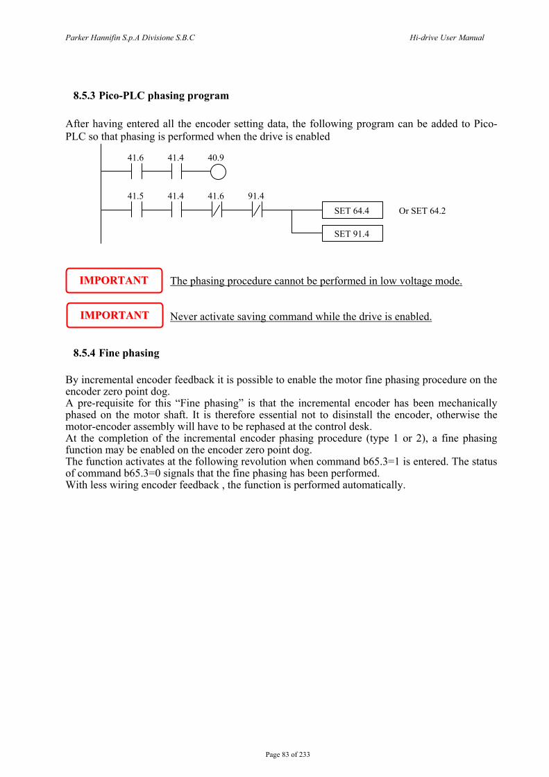
Parker Hannifin S.p.A Divisione S.B.C Hi-drive User Manual
Page 83 of 233
8.5.3 Pico-PLC phasing program After having entered all the encoder setting data, the following program can be added to Pico-PLC so that phasing is performed when the drive is enabled
The phasing procedure cannot be performed in low voltage mode.
Never activate saving command while the drive is enabled.
8.5.4 Fine phasing
By incremental encoder feedback it is possible to enable the motor fine phasing procedure on the encoder zero point dog. A pre-requisite for this “Fine phasing” is that the incremental encoder has been mechanically phased on the motor shaft. It is therefore essential not to disinstall the encoder, otherwise the motor-encoder assembly will have to be rephased at the control desk. At the completion of the incremental encoder phasing procedure (type 1 or 2), a fine phasing function may be enabled on the encoder zero point dog. The function activates at the following revolution when command b65.3=1 is entered. The status of command b65.3=0 signals that the fine phasing has been performed. With less wiring encoder feedback , the function is performed automatically.
41.6 41.4 40.9
41.5 41.4 41.6 91.4SET 64.4
SET 91.4
Or SET 64.2
IIMMPPOORRTTAANNTT
IIMMPPOORRTTAANNTT
Parker Hannifin S.p.A Divisione S.B.C Hi-drive User Manual
Page 84 of 233
8.5.5 Phasing procedure for encoder with EnDat o Hiperface interface The procedure of encoder phasing is not necessary with Parker Hannifin Divisione S.B.C.’s motor, but when the system requires the phasing, the procedure 1 and 2 of the phasing is the same for incremental encoder (see paragraph “phasing procedure”) and it must finalized as follows. With EnDat or Hiperface interface, single turn or multiturn, after the phasing is possible to save this information so at every start up the phasing procedure isn’t necessary; for take it, to bring the motor shaft in the position that Pr28=0, disable the drive and save with command b64.8=1. After this command is necessary start again the drive. Alternative to this procedure, disable the drive and disconnect the motor cable, the motor can rotate even if it is installed inside the equipment (any emergency brake disabled), with motor is available to supply a positive tension between phase B and C respect the phase A (it’s important to verify that the phase-phase resistance limits the current to the rated value) so that the shaft aligned (only for S.B.C. motor, for other type see the paragraph “ motor phases”), set the command b64.8=1 and start again the drive.
8.5.6 Motor phases In this paragraph is showed a procedure not necessary for the motors of the S.B.C. Division, essential for the motor connection, because allows to find the motor phases (A=U, B=V, C=W).
The procedures shown in this document are dangerous for the operator and could damage the motor under test. A qualified and trained personnel with advanced skills in electronics and drive technology is therefore needed, the operator must be sure that these procedures are proceeding in safety condition.
Necessary instruments: power supply 24Vdc with output current equal or higher to the rated current of the motor under test. Verify that the phase-phase resistance of the motor limits the current at the rated value with 24V voltage applied.
Necessary requisites: motor free without load and inertia applied.
Procedure: connect the positive pin of the 24Vdc supply voltage at one motor phase (assign name A at this phase). Connect the negative pin at one of the other phases (at random). Feeding the circuit, the rotor will turn and to assume a new position. Observing the motor shaft, move the negative pin of the 24Vdc voltage on the other phase: if the rotor turns counter-clockwise (watching frontally the drive shaft), the phase connected to the negative pin is the phase C, otherwise if the rotor turns clockwise this phase connected to the negative pin is the phase B (*).
Result: after to have connected the motor and the device of feedback to the drive, the counter of the feedback increases if the motor turns clockwise, and decrease if turns counter-clockwise sense.
(*) To avoid to damage the motor winding, to power the circuit only for the necessary time.

Parker Hannifin S.p.A Divisione S.B.C Hi-drive User Manual
Page 85 of 233
8.6 Speed control SPEED LOOP: The main task of a converter is to control motor speed so that it follows as faithfully as possible the speed request that is generally known as the REFERENCE. Faithfully following the reference means that the motor speed should equal the reference in static conditions and also that the motor speed is as equal as possible to the speed requested during dynamic conditions. To carry out this task, the converter must know some of the features both of the motor used and of the mechanical part attached to it. This information is communicated to the converter by the so-called ADJUSTMENT PARAMETERS. ERROR: The error is the difference between the reference speed and the motor speed. The error size is used by the speed loop in order to evaluate the level of current to be supplied to the motor. TORQUE: The current that circulates in the motor windings is transformed in torque, thereby allowing the motor to accelerate or decelerate. GAIN: Given the typical applications of the Hi-drive, any occurrence of the term gain in this document is referred to the rigidity of the axis, better known as STIFFNESS. In order to better illustrate what the term STIFFNESS means, let’s imagine a motor controlled by a converter with a requested speed of zero. The motor shaft will appear still. However, if a torque is applied to the shaft, this will demonstrate an angle proportional to the torque applied. Suppose we apply the motor rated torque and measure the STIFFNESS in degrees. The degrees measured will be the index of the quality of the regulator as parameterized. Of course this is not the only quality index.
8.7 Speed control adjustment
WHAT IS NEEDED In order to correctly adjust a Hi-drive converter an oscilloscope is required. A speed probe and a current probe will be connected at “monitor output 1” and at “monitor output 2”on terminal block X5 (Pin 8 and 7, whereas Pin 6 is “common”). By default, the drive monitors the Pr0 on screen 1, and Pr35 on screen 2 (see the description of key parameters and the section about programmable outputs). See the chapter “Inputs and outputs” for the technical features of outputs. terminal block X5” The drive configuration software MotionWiz includes an “oscilloscope” function that recreates an oscilloscope via a serial link. If it is not possible to use an oscilloscope, a more approximate but applicable adjustment method will be illustrated at the end of this section.
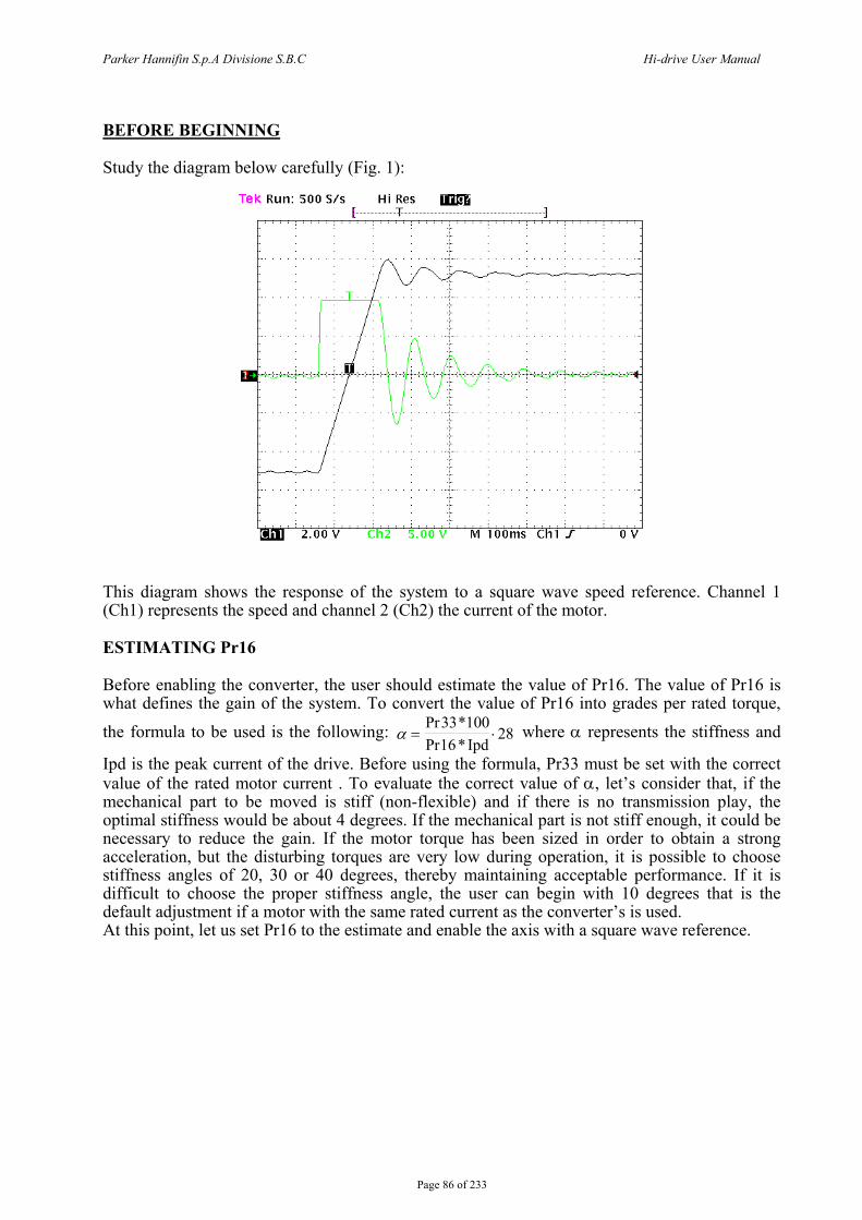
Parker Hannifin S.p.A Divisione S.B.C Hi-drive User Manual
Page 86 of 233
BEFORE BEGINNING
Study the diagram below carefully (Fig. 1):
This diagram shows the response of the system to a square wave speed reference. Channel 1 (Ch1) represents the speed and channel 2 (Ch2) the current of the motor.
ESTIMATING Pr16
Before enabling the converter, the user should estimate the value of Pr16. The value of Pr16 is what defines the gain of the system. To convert the value of Pr16 into grades per rated torque,
the formula to be used is the following: α = ⋅Pr *Pr *
33 10016
28Ipd
where α represents the stiffness and
Ipd is the peak current of the drive. Before using the formula, Pr33 must be set with the correct value of the rated motor current . To evaluate the correct value of α, let’s consider that, if the mechanical part to be moved is stiff (non-flexible) and if there is no transmission play, the optimal stiffness would be about 4 degrees. If the mechanical part is not stiff enough, it could be necessary to reduce the gain. If the motor torque has been sized in order to obtain a strong acceleration, but the disturbing torques are very low during operation, it is possible to choose stiffness angles of 20, 30 or 40 degrees, thereby maintaining acceptable performance. If it is difficult to choose the proper stiffness angle, the user can begin with 10 degrees that is the default adjustment if a motor with the same rated current as the converter’s is used. At this point, let us set Pr16 to the estimate and enable the axis with a square wave reference.
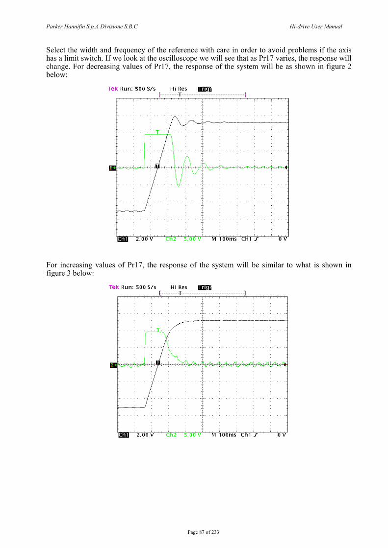
Parker Hannifin S.p.A Divisione S.B.C Hi-drive User Manual
Page 87 of 233
Select the width and frequency of the reference with care in order to avoid problems if the axis has a limit switch. If we look at the oscilloscope we will see that as Pr17 varies, the response will change. For decreasing values of Pr17, the response of the system will be as shown in figure 2 below:
For increasing values of Pr17, the response of the system will be similar to what is shown in figure 3 below:
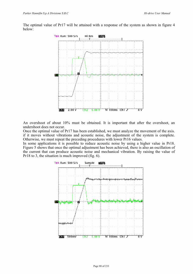
Parker Hannifin S.p.A Divisione S.B.C Hi-drive User Manual
Page 88 of 233
The optimal value of Pr17 will be attained with a response of the system as shown in figure 4 below:
An overshoot of about 10% must be obtained. It is important that after the overshoot, an undershoot does not occur. Once the optimal value of Pr17 has been established, we must analyze the movement of the axis. if it moves without vibrations and acoustic noise, the adjustment of the system is complete. Otherwise, we must repeat the preceding procedures with lower Pr16 values. In some applications it is possible to reduce acoustic noise by using a higher value in Pr18. Figure 5 shows that once the optimal adjustment has been achieved, there is also an oscillation of the current that can produce acoustic noise and mechanical vibration. By raising the value of Pr18 to 3, the situation is much improved (fig. 6).
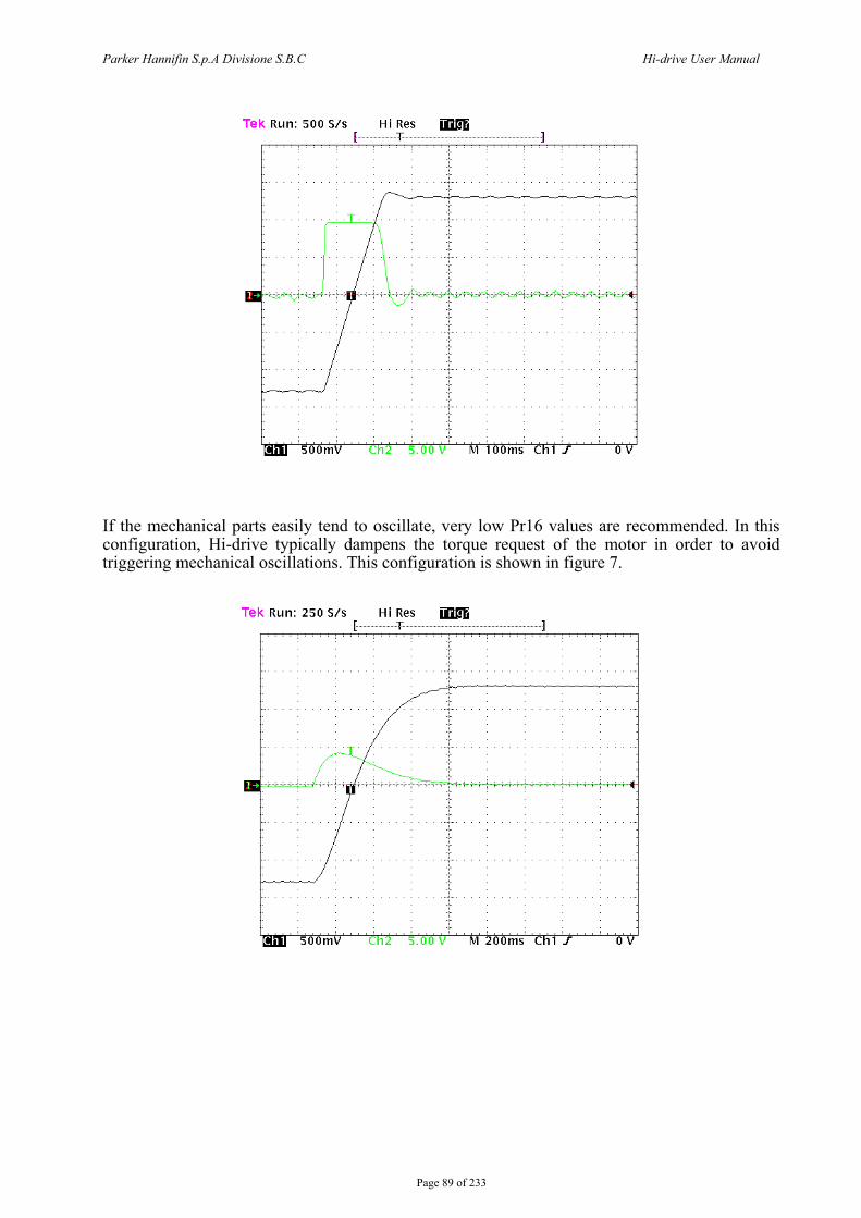
Parker Hannifin S.p.A Divisione S.B.C Hi-drive User Manual
Page 89 of 233
If the mechanical parts easily tend to oscillate, very low Pr16 values are recommended. In this configuration, Hi-drive typically dampens the torque request of the motor in order to avoid triggering mechanical oscillations. This configuration is shown in figure 7.
Parker Hannifin S.p.A Divisione S.B.C Hi-drive User Manual
Page 90 of 233
ADJUSTMENT WITHOUT INSTRUMENTATION If you do not have an oscilloscope, you must:
- Determine the value of Pr16 as described above. - Determine parameter Pr17 using the following formula:
peak
tot
NmJ⋅⋅
⋅=16Pr41.153148817Pr
where: Jtot is the total inertia (motor + load) expressed in kgm2. peakNm is the available torque with the converter peak current.
- Enable the converter and use the external control to move the axis. Move Pr17 to find the value where the axis seems to move best.
- Estimate the value of Pr18 using the following formula:
216Pr17Pr68.018Pr ⋅⋅=
If the result is less than 1, Pr18 must be set to 1.
If the adjustment is not satisfactory, repeat the procedure with lower values of Pr16.
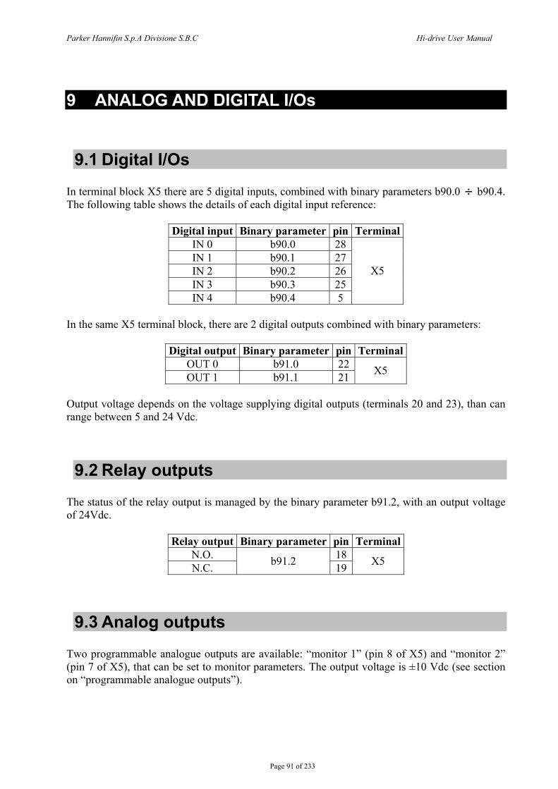
Parker Hannifin S.p.A Divisione S.B.C Hi-drive User Manual
Page 91 of 233
9 ANALOG AND DIGITAL I/Os
9.1 Digital I/Os In terminal block X5 there are 5 digital inputs, combined with binary parameters b90.0 b90.4. The following table shows the details of each digital input reference:
Digital input Binary parameter pin Terminal IN 0 b90.0 28IN 1 b90.1 27IN 2 b90.2 26IN 3 b90.3 25IN 4 b90.4 5
X5
In the same X5 terminal block, there are 2 digital outputs combined with binary parameters:
Digital output Binary parameter pin Terminal OUT 0 b91.0 22OUT 1 b91.1 21 X5
Output voltage depends on the voltage supplying digital outputs (terminals 20 and 23), than can range between 5 and 24 Vdc.
9.2 Relay outputs The status of the relay output is managed by the binary parameter b91.2, with an output voltage of 24Vdc.
Relay output Binary parameter pin Terminal N.O. 18N.C. b91.2 19 X5
9.3 Analog outputs Two programmable analogue outputs are available: “monitor 1” (pin 8 of X5) and “monitor 2” (pin 7 of X5), that can be set to monitor parameters. The output voltage is ±10 Vdc (see section on “programmable analogue outputs”).
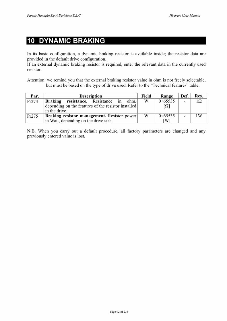
Parker Hannifin S.p.A Divisione S.B.C Hi-drive User Manual
Page 92 of 233
10 DYNAMIC BRAKING In its basic configuration, a dynamic braking resistor is available inside; the resistor data are provided in the default drive configuration. If an external dynamic braking resistor is required, enter the relevant data in the currently used resistor. Attention: we remind you that the external braking resistor value in ohm is not freely selectable,
but must be based on the type of drive used. Refer to the “Technical features” table.
Par. Description Field Range Def. Res. Pr274 Braking resistance. Resistance in ohm,
depending on the features of the resistor installed in the drive.
W 0÷65535 [Ω]
- 1Ω
Pr275 Braking resistor management. Resistor power in Watt, depending on the drive size.
W 0÷65535 [W]
- 1W
N.B. When you carry out a default procedure, all factory parameters are changed and any previously entered value is lost.
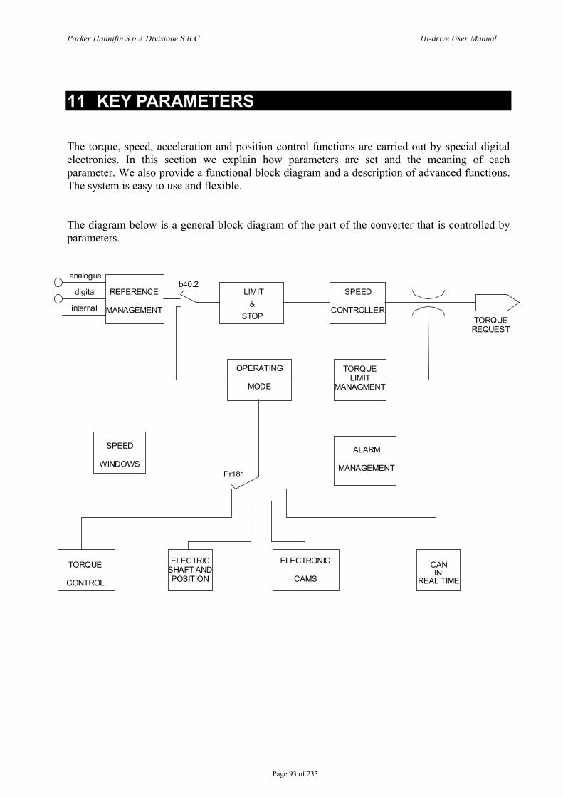
Parker Hannifin S.p.A Divisione S.B.C Hi-drive User Manual
Page 93 of 233
11 KEY PARAMETERS The torque, speed, acceleration and position control functions are carried out by special digital electronics. In this section we explain how parameters are set and the meaning of each parameter. We also provide a functional block diagram and a description of advanced functions. The system is easy to use and flexible. The diagram below is a general block diagram of the part of the converter that is controlled by parameters.
REFERENCE
MANAGEMENT
LIMIT &
STOP
SPEED
CONTROLLER
OPERATING
MODE
TORQUE LIMIT
MANAGMENT
TORQUE REQUEST
analogue
digital
internal
SPEED
WINDOWS
TORQUE
CONTROL
ELECTRIC SHAFT AND POSITION
CAN
ALARM
MANAGEMENT
b40.2
Pr181
IN REAL TIME
ELECTRONIC
CAMS
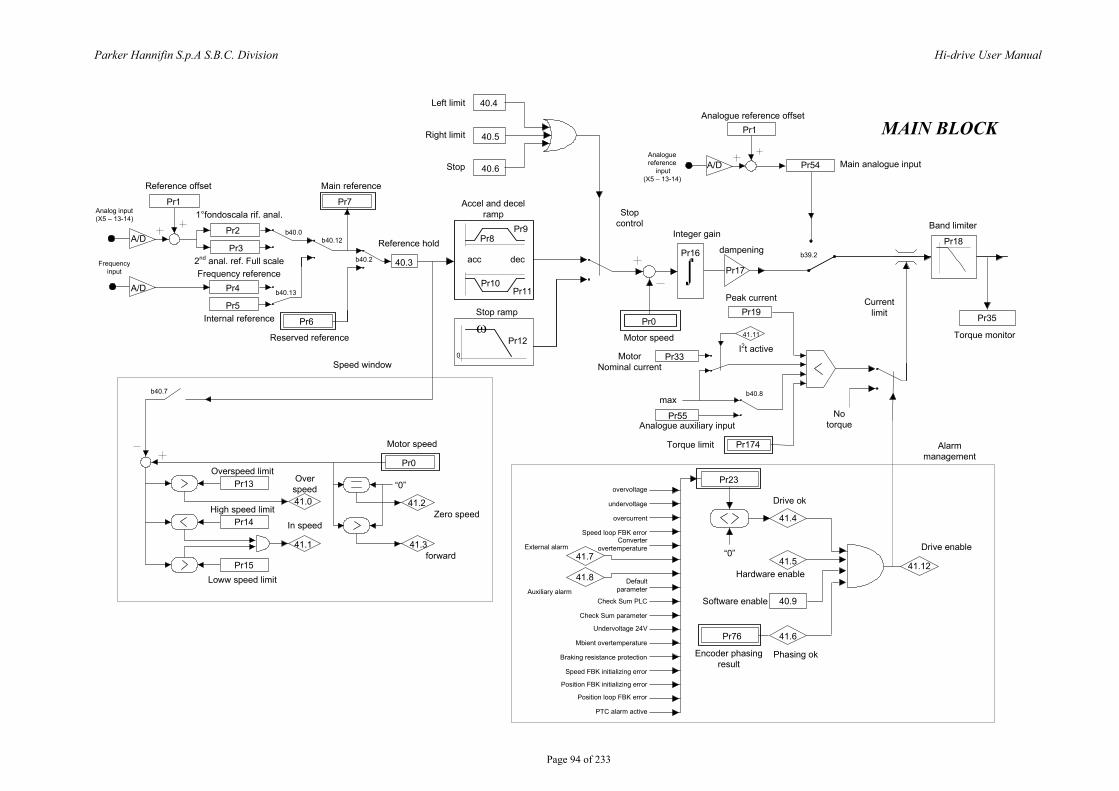
Parker Hannifin S.p.A S.B.C. Division Hi-drive User Manual
Page 94 of 233
Pr16
Pr10Pr17
Pr9
Pr11
Pr8
Pr12
Pr19
41.11
Pr33
40.3
Pr7
Pr6
Pr55
Pr174
Notorque
Pr18
Pr35
Pr1
Pr5
Pr4
Pr3
Pr2A/D
A/D
Accel and decel ramp
acc dec
max
Band limiter
Torque monitor
Torque limit
Analogue auxiliary input
MotorNominal current
I2t active
Peak current
Integer gain
dampening
Pr0
Motor speed
Stop ramp
Reference hold
Main reference
Reserved reference
Internal reference
Frequency reference
Reference offset
1°fondoscala rif. anal.
2nd anal. ref. Full scale
b40.0b40.12
b40.2
b40.13
b40.8
Pr0
41.2
41.3
41.0
41.1
Pr13
Pr14
Pr15
Motor speed
Zero speed
forward
Overspeed limit
High speed limit
Loww speed limit
Over speed
In speed
b40.7
Pr23
41.4
41.541.7
41.8
40.9
Pr76 41.6
41.12“0”
Drive enable
Software enable
Hardware enable
Encoder phasingresult
Phasing ok
Drive okovervoltage
undervoltage
External alarm
Auxiliary alarm
PTC alarm active
40.4
40.5
40.6
Left limit
Right limit
Stop
Currentlimit
Stopcontrol
Speed window
Alarmmanagement
overcurrent
Speed loop FBK errorConverter
overtemperature
Default parameter
Check Sum parameter
Undervoltage 24V
Mbient overtemperature
Braking resistance protection
Speed FBK initializing error
Position FBK initializing error
Position loop FBK error
Check Sum PLC
0
Pr1
Pr54Analoguereference
input (X5 – 13-14)
Analogue reference offset
Main analogue inputA/D
b39.2
Analog input (X5 – 13-14)
Frequencyinput
“0”
MAIN BLOCK
ω
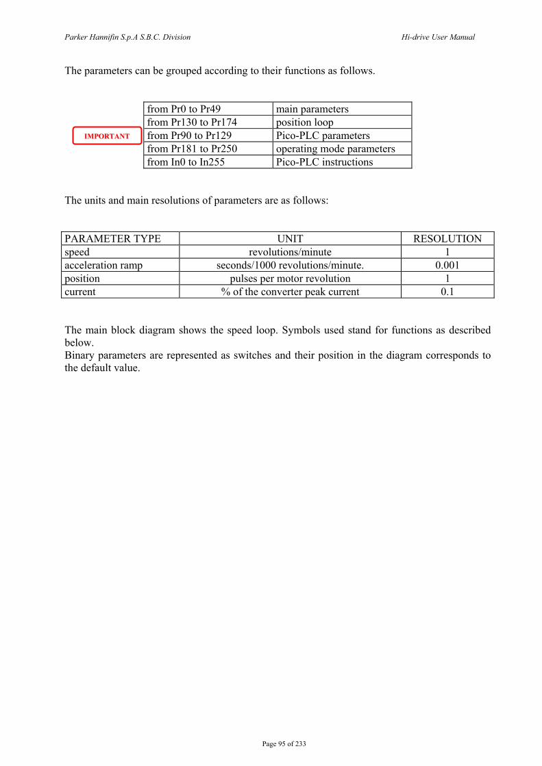
Parker Hannifin S.p.A S.B.C. Division Hi-drive User Manual
Page 95 of 233
The parameters can be grouped according to their functions as follows.
from Pr0 to Pr49 main parameters from Pr130 to Pr174 position loop from Pr90 to Pr129 Pico-PLC parameters from Pr181 to Pr250 operating mode parameters from In0 to In255 Pico-PLC instructions
The units and main resolutions of parameters are as follows: PARAMETER TYPE UNIT RESOLUTION speed revolutions/minute 1 acceleration ramp seconds/1000 revolutions/minute. 0.001 position pulses per motor revolution 1 current % of the converter peak current 0.1 The main block diagram shows the speed loop. Symbols used stand for functions as described below. Binary parameters are represented as switches and their position in the diagram corresponds to the default value.
IIMMPPOORRTTAANNTT
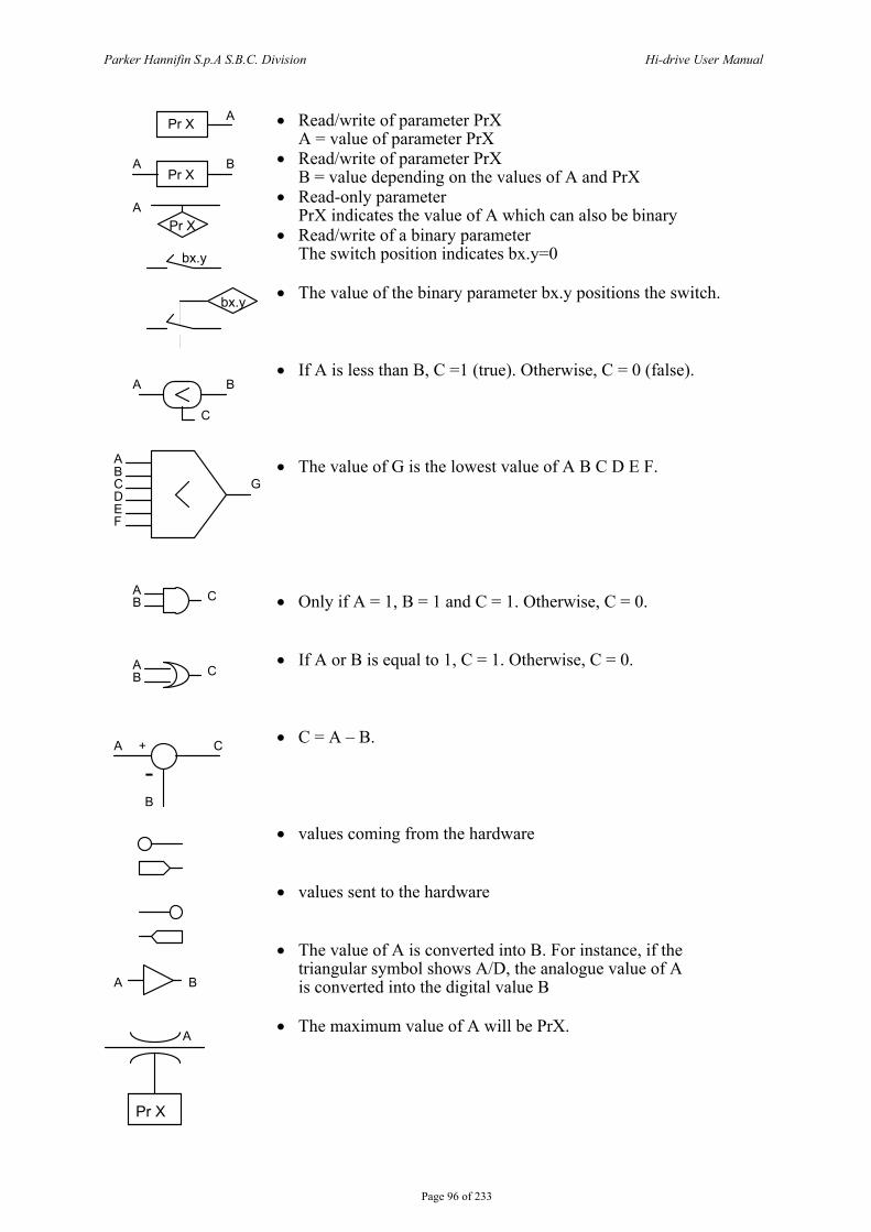
Parker Hannifin S.p.A S.B.C. Division Hi-drive User Manual
Page 96 of 233
• Read/write of parameter PrX A = value of parameter PrX • Read/write of parameter PrX B = value depending on the values of A and PrX • Read-only parameter PrX indicates the value of A which can also be binary • Read/write of a binary parameter The switch position indicates bx.y=0 • The value of the binary parameter bx.y positions the switch. • If A is less than B, C =1 (true). Otherwise, C = 0 (false). • The value of G is the lowest value of A B C D E F. • Only if A = 1, B = 1 and C = 1. Otherwise, C = 0. • If A or B is equal to 1, C = 1. Otherwise, C = 0. • C = A – B. • values coming from the hardware • values sent to the hardware • The value of A is converted into B. For instance, if the triangular symbol shows A/D, the analogue value of A is converted into the digital value B • The maximum value of A will be PrX.
A
A B
A
A B
C
ABCD
FE
G
A CB
A CB
A
B
C+
-
A B
Pr X
Pr X
Pr X
bx.y
bx.y
A
Pr X
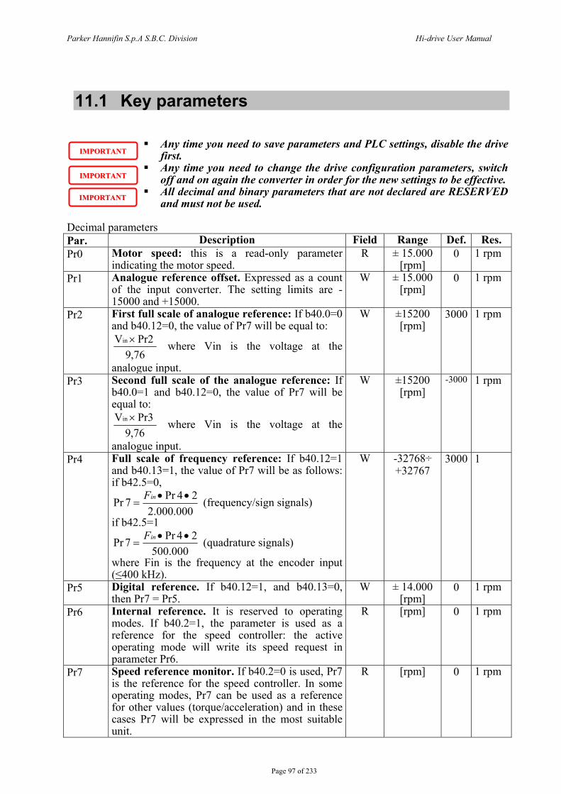
Parker Hannifin S.p.A S.B.C. Division Hi-drive User Manual
Page 97 of 233
11.1 Key parameters
Any time you need to save parameters and PLC settings, disable the drive first.
Any time you need to change the drive configuration parameters, switch off and on again the converter in order for the new settings to be effective.
All decimal and binary parameters that are not declared are RESERVED and must not be used.
Decimal parameters Par. Description Field Range Def. Res. Pr0 Motor speed: this is a read-only parameter
indicating the motor speed. R ± 15.000
[rpm] 0 1 rpm
Pr1 Analogue reference offset. Expressed as a count of the input converter. The setting limits are -15000 and +15000.
W ± 15.000 [rpm]
0 1 rpm
Pr2 First full scale of analogue reference: If b40.0=0 and b40.12=0, the value of Pr7 will be equal to:
76,9 Pr2 Vin × where Vin is the voltage at the
analogue input.
W ±15200 [rpm]
3000 1 rpm
Pr3 Second full scale of the analogue reference: If b40.0=1 and b40.12=0, the value of Pr7 will be equal to:
76,9 Pr3 Vin × where Vin is the voltage at the
analogue input.
W ±15200 [rpm]
-3000 1 rpm
Pr4 Full scale of frequency reference: If b40.12=1 and b40.13=1, the value of Pr7 will be as follows: if b42.5=0,
000.000.22 4Pr 7Pr ••
=inF (frequency/sign signals)
if b42.5=1
000.5002 4Pr 7Pr ••
=inF (quadrature signals)
where Fin is the frequency at the encoder input (≤400 kHz).
W -32768÷ +32767
3000 1
Pr5 Digital reference. If b40.12=1, and b40.13=0, then Pr7 = Pr5.
W ± 14.000 [rpm]
0 1 rpm
Pr6 Internal reference. It is reserved to operating modes. If b40.2=1, the parameter is used as a reference for the speed controller: the active operating mode will write its speed request in parameter Pr6.
R [rpm] 0 1 rpm
Pr7 Speed reference monitor. If b40.2=0 is used, Pr7 is the reference for the speed controller. In some operating modes, Pr7 can be used as a reference for other values (torque/acceleration) and in these cases Pr7 will be expressed in the most suitable unit.
R [rpm] 0 1 rpm
IIMMPPOORRTTAANNTT
IIMMPPOORRTTAANNTT
IIMMPPOORRTTAANNTT
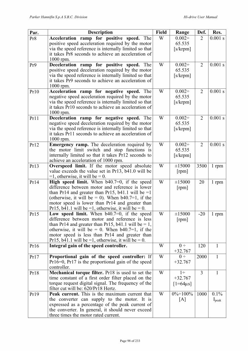
Parker Hannifin S.p.A S.B.C. Division Hi-drive User Manual
Page 98 of 233
Par. Description Field Range Def. Res. Pr8 Acceleration ramp for positive speed. The
positive speed acceleration required by the motor via the speed reference is internally limited so that it takes Pr8 seconds to achieve an acceleration of 1000 rpm.
W 0.002÷ 65.535
[s/krpm]
2 0.001 s
Pr9 Deceleration ramp for positive speed. The positive speed deceleration required by the motor via the speed reference is internally limited so that it takes Pr9 seconds to achieve an acceleration of 1000 rpm.
W 0.002÷ 65.535
[s/krpm]
2 0.001 s
Pr10 Acceleration ramp for negative speed. The negative speed acceleration required by the motor via the speed reference is internally limited so that it takes Pr10 seconds to achieve an acceleration of 1000 rpm.
W 0.002÷ 65.535
[s/krpm]
2 0.001 s
Pr11 Deceleration ramp for negative speed. The negative speed deceleration required by the motor via the speed reference is internally limited so that it takes Pr11 seconds to achieve an acceleration of 1000 rpm.
W 0.002÷ 65.535
[s/krpm]
2 0.001 s
Pr12 Emergency ramp. The deceleration required by the motor limit switch and stop functions is internally limited so that it takes Pr12 seconds to achieve an acceleration of 1000 rpm.
W 0.002÷ 65.535
[s/krpm]
2 0.001 s
Pr13 Overspeed limit. If the motor speed absolute value exceeds the value set in Pr13, b41.0 will be =1, otherwise, it will be = 0.
W ±15000 [rpm]
3500 1 rpm
Pr14 High speed limit. When b40.7=0, if the speed difference between motor and reference is lower than Pr14 and greater than Pr15, b41.1 will be =1 (otherwise, it will be = 0). When b40.7=1, if the motor speed is lower than Pr14 and greater than Pr15, b41.1 will be =1, otherwise, it will be = 0.
W ±15000 [rpm]
20 1 rpm
Pr15 Low speed limit. When b40.7=0, if the speed difference between motor and reference is less than Pr14 and greater than Pr15, b41.1 will be = 1, otherwise, it will be = 0. When b40.7=1, if the motor speed is less than Pr14 and greater than Pr15, b41.1 will be =1, otherwise, it will be = 0.
W ±15000 [rpm]
-20 1 rpm
Pr16 Integral gain of the speed controller. W 0 ÷ +32.767
120 1
Pr17 Proportional gain of the speed controller: If Pr16=0, Pr17 is the proportional gain of the speed controller.
W 0 ÷ +32.767
2000 1
Pr18 Mechanical torque filter. Pr18 is used to set the time constant of a first order filter placed on the torque request digital signal. The frequency of the filter cut will be: 620/Pr18 Hertz.
W 1÷ +32.767 [1=64μs]
3 1
Pr19 Peak current. This is the maximum current that the converter can supply to the motor. It is expressed as a percentage of the peak current of the converter. In general, it should never exceed three times the motor rated current.
W 0%÷100% [A]
1000 0.1% Ipeak
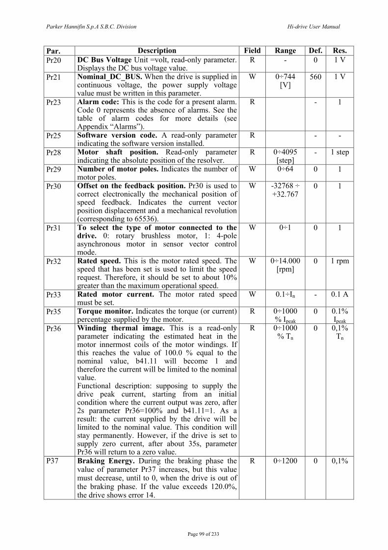
Parker Hannifin S.p.A S.B.C. Division Hi-drive User Manual
Page 99 of 233
Par. Description Field Range Def. Res. Pr20 DC Bus Voltage Unit =volt, read-only parameter.
Displays the DC bus voltage value. R - 0 1 V
Pr21 Nominal_DC_BUS. When the drive is supplied in continuous voltage, the power supply voltage value must be written in this parameter.
W 0÷744 [V]
560 1 V
Pr23 Alarm code: This is the code for a present alarm. Code 0 represents the absence of alarms. See the table of alarm codes for more details (see Appendix “Alarms”).
R - 1
Pr25 Software version code. A read-only parameter indicating the software version installed.
R - -
Pr28 Motor shaft position. Read-only parameter indicating the absolute position of the resolver.
R 0÷4095 [step]
- 1 step
Pr29 Number of motor poles. Indicates the number of motor poles.
W 0÷64 0 1
Pr30 Offset on the feedback position. Pr30 is used to correct electronically the mechanical position of speed feedback. Indicates the current vector position displacement and a mechanical revolution (corresponding to 65536).
W -32768 ÷ +32.767
0 1
Pr31 To select the type of motor connected to the drive. 0: rotary brushless motor, 1: 4-pole asynchronous motor in sensor vector control mode.
W 0÷1 0 1
Pr32 Rated speed. This is the motor rated speed. The speed that has been set is used to limit the speed request. Therefore, it should be set to about 10% greater than the maximum operational speed.
W 0÷14.000 [rpm]
0 1 rpm
Pr33 Rated motor current. The motor rated speed must be set.
W 0.1÷In - 0.1 A
Pr35 Torque monitor. Indicates the torque (or current) percentage supplied by the motor.
R 0÷1000 % Ipeak
0 0.1% Ipeak
Pr36 Winding thermal image. This is a read-only parameter indicating the estimated heat in the motor innermost coils of the motor windings. If this reaches the value of 100.0 % equal to the nominal value, b41.11 will become 1 and therefore the current will be limited to the nominal value. Functional description: supposing to supply the drive peak current, starting from an initial condition where the current output was zero, after 2s parameter Pr36=100% and b41.11=1. As a result: the current supplied by the drive will be limited to the nominal value. This condition will stay permanently. However, if the drive is set to supply zero current, after about 35s, parameter Pr36 will return to a zero value.
R 0÷1000 % Tn
0 0,1% Tn
P37 Braking Energy. During the braking phase the value of parameter Pr37 increases, but this value must decrease, until to 0, when the drive is out of the braking phase. If the value exceeds 120.0%, the drive shows error 14.
R 0÷1200 0 0,1%
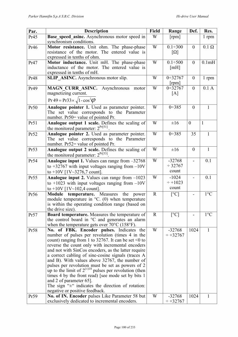
Parker Hannifin S.p.A S.B.C. Division Hi-drive User Manual
Page 100 of 233
Par. Description Field Range Def. Res. Pr45 Base_speed_asinc. Asynchronous motor speed in
synchronism conditions. W [rpm] 1 rpm
Pr46 Motor resistance. Unit ohm. The phase-phase resistance of the motor. The entered value is expressed in tenths of ohm.
W 0.1÷300 [Ω]
0 0.1 Ω
Pr47 Motor inductance. Unit mH. The phase-phase inductance of the motor. The entered value is expressed in tenths of mH.
W 0.1÷500 [mH]
0 0.1mH
Pr48 SLIP_ASINC. Asynchronous motor slip. W 0÷32767 [rpm]
0 1 rpm
Pr49 MAGN_CURR_ASINC. Asynchronous motor magnetizing current.
ϕ2cos-1 Pr33 49Pr ×=
W 0÷32767 [A]
0 0.1 A
Pr50 Analogue pointer 1. Used as parameter pointer. The set value corresponds to the Parameter number. Pr50= value of pointed Pr.
W 0÷385 0 1
Pr51 Analogue output 1 scale. Defines the scaling of the monitored parameter: 2Pr[51] .
W ±16 0 1
Pr52 Analogue pointer 2. Used as parameter pointer. The set value corresponds to the Parameter number. Pr52= value of pointed Pr.
W 0÷385 35 1
Pr53 Analogue output 2 scale. Defines the scaling of the monitored parameter: 2Pr[53].
W ±16 0 1
Pr54 Analogue input 1. Values can range from –32768 to +32767 with input voltages ranging from –10V to +10V [1V~3276,7 count].
W -32768 ÷ 32767
count
- 0.1
Pr55 Analogue input 2. Values can range from –1023 to +1023 with input voltages ranging from –10V to +10V [1V~102,4 count].
W -1024 ÷ +1023
count
- 0.1
Pr56 Module temperature. Measures the power module temperature in °C. (0) when temperature is within the operating condition range (based on the drive size).
R [°C] - 1°C
Pr57 Board temperature. Measures the temperature of the control board in °C and generates an alarm when the temperature gets over 70°C (158°F).
R [°C] - 1°C
Pr58 No. of FBK. Encoder pulses. Indicates the number of pulses per revolution (times 4 in the count) ranging from 1 to 32767. It can be set <0 to reverse the count only with incremental encoders and not with SinCos encoders, as the latter require a correct cabling of sine-cosine signals (traces A and B). With values above 32767, the number of pulses per revolution must be set as powers of 2 up to the limit of 2(±)18 pulses per revolution (then times 4 by the front read) [see mode set by bits 1 and 2 of parameter 65]. The sign “±“ indicates the direction of rotation: negative or positive feedback.
W -32768 ÷ +32767
1024 1
Pr59 No. of IN. Encoder pulses Like Parameter 58 but exclusively dedicated to incremental encoders.
W -32768 ÷ +32767
1024 1

Parker Hannifin S.p.A S.B.C. Division Hi-drive User Manual
Page 101 of 233
Par. Description Field Range Def. Res. Pr60 Number of resolver poles. The pole number
setting has the following values: 2, 4 or 8; where the limit speed is 14000rpm for 2 poles, 7000rpm for 4 poles and 3500rpm for 8 poles. N.B. when the resolver is not used, leave parameter Pr60=2.
W 2, 4 or 8 2 1
Pr62 Input B selection 0 Sincos + EnDat 1 Sincos 2 Less wiring 3 Square incremental encoder 4 F/D incremental encoder 5 square IN2 IN3 (24V) inputs 6 IN2 IN3 (24V) F/D inputs. 7 Sincos + Hiperface (The setting is enabled at the next power on ).
W 0 ÷ 7 0 1
Pr63 Input C selection 3 Square incremental encoder 4 F/D incremental encoder 5 square IN2 IN3 (24V) inputs 6 IN2 IN3 (24V) F/D inputs (The setting is enabled at the next power on ).
W 2 ÷ 6 3 1
Pr69:68 Multiturn zeroing preset. In this register the machine resetting value is entered. The value can be different from zero.
W -32768 ÷ +32767
0 1
Pr71 Enc. simulation parameter pointer Read always in Long at 32 bit; the selected parameter is the low word. If you select a single word, mind the significance of the following high word, which is also read. E.g. if we read Pr0 and the motor is halted, but the speed has a value of +/-1 Rpm, the pointer will read +1 and write +1, at –1 it reads the long Pr0:Pr1 word, and therefore 65535; the encoder simulator will in this case be moved by the same value.
W 0÷385 0 1
Enc. Simulation pulses per revolution. If b70.0=0, values range from 4 to 65535 pulses per revolution; if b70.0=1 is the exponent and the maximum value that can be entered is 18, Default=1024 is the number of pulses per revolution used in the encoder simulation. The maximum frequency is 400 kHz.
[ ] [ ] [ ]kHzrpmsFin 400
minsec/ 60 peedencoder pulse
≤×
=
If b70.0=0, the range is from 0 to 65535 pulses/turn.
0 ÷ +32767
Pr72
If b70.0=1, the value of parameter is the exponent, and the max value is 18.
W
0 ÷ 18
1024 1
Pr76 Enc. phasing result. When the encoder phasing is completed, this parameter indicates if the phasing is OK or if it must be repeated taking into account the previously disregarded conditions.
R 0 ÷ 1 0 1
Pr77 Enc. address CAN IN. W 0 Pr167 Drive type code. R
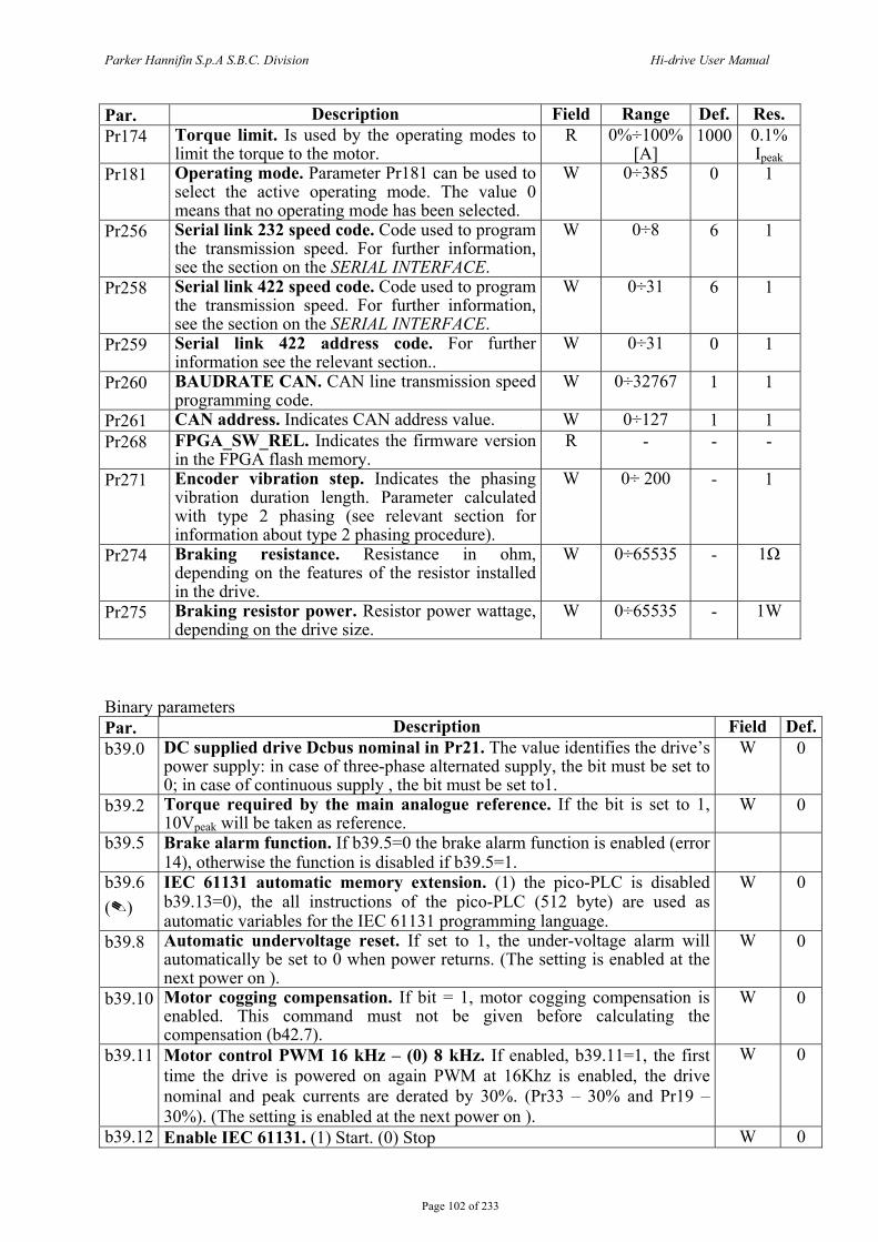
Parker Hannifin S.p.A S.B.C. Division Hi-drive User Manual
Page 102 of 233
Par. Description Field Range Def. Res. Pr174 Torque limit. Is used by the operating modes to
limit the torque to the motor. R 0%÷100%
[A] 1000 0.1%
Ipeak Pr181 Operating mode. Parameter Pr181 can be used to
select the active operating mode. The value 0 means that no operating mode has been selected.
W 0÷385 0 1
Pr256 Serial link 232 speed code. Code used to program the transmission speed. For further information, see the section on the SERIAL INTERFACE.
W 0÷8 6 1
Pr258 Serial link 422 speed code. Code used to program the transmission speed. For further information, see the section on the SERIAL INTERFACE.
W 0÷31 6 1
Pr259 Serial link 422 address code. For further information see the relevant section..
W 0÷31 0 1
Pr260 BAUDRATE CAN. CAN line transmission speed programming code.
W 0÷32767 1 1
Pr261 CAN address. Indicates CAN address value. W 0÷127 1 1 Pr268 FPGA_SW_REL. Indicates the firmware version
in the FPGA flash memory. R - - -
Pr271 Encoder vibration step. Indicates the phasing vibration duration length. Parameter calculated with type 2 phasing (see relevant section for information about type 2 phasing procedure).
W 0÷ 200 - 1
Pr274 Braking resistance. Resistance in ohm, depending on the features of the resistor installed in the drive.
W 0÷65535 - 1Ω
Pr275 Braking resistor power. Resistor power wattage, depending on the drive size.
W 0÷65535 - 1W
Binary parameters Par. Description Field Def.b39.0 DC supplied drive Dcbus nominal in Pr21. The value identifies the drive’s
power supply: in case of three-phase alternated supply, the bit must be set to 0; in case of continuous supply , the bit must be set to1.
W 0
b39.2 Torque required by the main analogue reference. If the bit is set to 1, 10Vpeak will be taken as reference.
W 0
b39.5 Brake alarm function. If b39.5=0 the brake alarm function is enabled (error 14), otherwise the function is disabled if b39.5=1.
b39.6 ()
IEC 61131 automatic memory extension. (1) the pico-PLC is disabled b39.13=0), the all instructions of the pico-PLC (512 byte) are used as automatic variables for the IEC 61131 programming language.
W 0
b39.8 Automatic undervoltage reset. If set to 1, the under-voltage alarm will automatically be set to 0 when power returns. (The setting is enabled at the next power on ).
W 0
b39.10 Motor cogging compensation. If bit = 1, motor cogging compensation is enabled. This command must not be given before calculating the compensation (b42.7).
W 0
b39.11 Motor control PWM 16 kHz – (0) 8 kHz. If enabled, b39.11=1, the first time the drive is powered on again PWM at 16Khz is enabled, the drive nominal and peak currents are derated by 30%. (Pr33 – 30% and Pr19 – 30%). (The setting is enabled at the next power on ).
W 0
b39.12 Enable IEC 61131. (1) Start. (0) Stop W 0
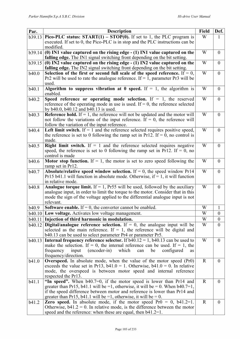
Parker Hannifin S.p.A S.B.C. Division Hi-drive User Manual
Page 103 of 233
Par. Description Field Def.b39.13 Pico-PLC status: START(1) – STOP(0). If set to 1, the PLC program is
executed. If set to 0, the Pico-PLC is in stop and the PLC instructions can be modified.
W 1
b39.14 (0) IN1 value captured on the rising edge - (1) IN1 value captured on the falling edge. The IN1 signal switching front depending on the bit setting.
W 0
b39.15 (0) IN2 value captured on the rising edge - (1) IN2 value captured on the falling edge. The IN2 signal switching front depending on the bit setting.
W 0
b40.0 Selection of the first or second full scale of the speed reference. If = 0, Pr2 will be used to rate the analogue reference. If = 1, parameter Pr3 will be used.
W 0
b40.1 Algorithm to suppress vibration at 0 speed. If = 1, the algorithm is enabled.
W 0
b40.2 Speed reference or operating mode selection. If = 1, the reserved reference of the operating mode in use is used. If = 0, the reference selected by b40.0, b40.12 and b40.13 is used.
W 0
b40.3 Reference hold. If = 1, the reference will not be updated and the motor will not follow the variations of the input reference. If = 0, the reference will follow the variation of the input reference.
W 0
b40.4 Left limit switch. If = 1 and the reference selected requires positive speed, the reference is set to 0 following the ramp set in Pr12. If = 0, no control is made.
W 0
b40.5 Right limit switch. If = 1 and the reference selected requires negative speed, the reference is set to 0 following the ramp set in Pr12. If = 0, no control is made
W 0
b40.6 Motor stop function. If = 1, the motor is set to zero speed following the ramp set in Pr12.
W 0
b40.7 Absolute/relative speed window selection. If = 0, the speed window Pr14 Pr15 b41.1 will function in absolute mode. Otherwise, if = 1, it will function in relative mode.
W 0
b40.8 Analogue torque limit. If = 1, Pr55 will be used, followed by the auxiliary analogue input, in order to limit the torque to the motor. Consider that in this mode the sign of the voltage applied to the differential analogue input is not relevant.
W 0
b40.9 Software enable. If = 0, the converter cannot be enabled. W 1 b40.10 Low voltage. Activates low voltage management. W 0 b40.11 Injection of third harmonic in modulation. W 0 b40.12 Digital/analogue reference selection. If = 0, the analogue input will be
selected as the main reference. If = 1, the reference will be digital and b40.13 can be used to select parameter Pr4 or parameter Pr5.
W 0
b40.13 Internal frequency reference selector. If b40.12 = 1, b40.13 can be used to make the selection. If = 0, the internal reference can be used. If = 1, the frequency input (encoder-in) which can be configured as frequency/direction.
W 0
b41.0 Overspeed. In absolute mode, when the value of the motor speed (Pr0) exceeds the value set in Pr13, b41.0 = 1. Otherwise, b41.0 = 0. In relative mode, the overspeed is between motor speed and internal reference respected the Pr13.
R 0
b41.1 “In speed”. When b40.7=0, if the motor speed is lower than Pr14 and greater than Pr15, b41.1 will be =1, otherwise, it will be = 0. When b40.7=1, if the speed difference between motor and reference is lower than Pr14 and greater than Pr15, b41.1 will be =1, otherwise, it will be = 0.
R 0
b41.2 Zero speed. In absolute mode, if the motor speed Pr0 = 0, b41.2=1. Otherwise, b41.2 = 0. In relative mode, is the difference between the motor speed and the reference: when these are equal, then b41.2=1.
R 0
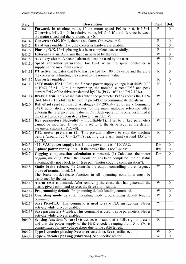
Parker Hannifin S.p.A S.B.C. Division Hi-drive User Manual
Page 104 of 233
Par. Description Field Def.b41.3 Forward. In absolute mode, if the motor speed Pr0 is > 0, b41.3=1.
Otherwise, b41. 3 = 0. In relative mode, b41.3=1 if the difference between the motor speed and the reference is > 0.
R 0
b41.4 Converter O.K. If = 1, there is no alarm. Otherwise, = 0. R 0 b41.5 Hardware enable. If =1, the converter hardware is enabled. R 0 b41.6 Phasing O.K. If =1, phasing has been completed successfully. R 1 b41.7 External alarm. An alarm that can be used by the user. W 0 b41.8 Auxiliary alarm. A second alarm that can be used by the user. W 0 b41.10 Speed controller saturation. b41.10=1 when the speed controller is
supplying the maximum current. R 1
b41.11 I2T active. Indicates that Pr36 has reached the 100.0 % value and therefore the converter is limiting the current to the nominal value.
R 0
b41.12 Converter enabled. R 0 b41.13 480V mode. If b41.13=1, the 3-phase power supply voltage is at 440V (400
+ 10%). If b41.13 = 1 at power up, the nominal current Pr33 and peak current Pr19 of the drive are derated by10% (Pr33-10% and Pr19-10%).
R 0
b41.14 Brake alarm. This bit indicates when the parameter Pr37 exceeds the 100% (b41.14=1). This bit can be used in pico-PLC to communicate the alarm.
W 0
b42.0 Ref. offset reset command. Analogue (if < 200mV) (auto reset). Command b42.0 automatically compensates for the main analogue reference offset entering the reference reset value in Pr1. Such operation is only performed if the offset to be compensated is lower than 200mV.
W 0
b42.1 Key parameters blocked(0) – modifiable(1). If set to 0, key parameters cannot be modified. If the bit is set to 1, the drive requires the default parameters again (if Pr23=0).
W 0
b42.2 PTC motor pre-alarm (1). This pre-alarm allows to stop the machine before (around 125°C – 257°F) reaching the alarm limit (around 135°C – 275°F).
R 0
b42.3 <150VAC power supply. It is 1 if the power line is < 150VAC. Rw 0 b42.4 3-phase power supply. It is 1 if the power line is not 3-phase. Rw 0 b42.7 Cogging compensation calculation command. (1) Calculates the motor
cogging mapping. When the calculation has been completed, the bit status automatically goes back to“0” (see par. “motor cogging compensation”).
Rw 0
b42.8 Static brake release. (1) Controls the output controlling the emergency brake of terminal block X3. The brake block-release function in all operating conditions must be performed by the user.
W 0
b42.10 Alarm reset command. After removing the cause that has generated the alarm, give a command to reset the drive alarm status.
W 0
b42.12 Programming default. Programming default loading command. W 0 b42.13 Operating mode default. Operating mode programming default loading
command. W 0
b42.14 Save Pico-PLC. This command is used to save PLC instructions. Never activate while drive is enabled.
W
b42.15 Save parameters + tables. This command is used to save parameters. Never activate while drive is enabled.
W
b64.0 Sensing function. When (1) is active, it means that a FBK sign is present and that the power supply of the FBK encoder, ranging from 5 to 8V, is compensated for any voltage drops due to the cable length.
R -
b64.2 Type 1 encoder phasing (vector orientation). See specific section. W 0 b64.4 Type 2 encoder phasing (vibration). See specific section. w 0

Parker Hannifin S.p.A S.B.C. Division Hi-drive User Manual
Page 105 of 233
Par. Description Field Def.b64.8 Phase value saving. The command saves the phase value on the encoder
EnDat (disables the drive and prevents any further enabling command. To enable the drive you’ll need to switch it off and on again).
W 0
b64.9 Multiturn position reset on encoder EnDat. Defines the machine “zero” position. The value is set in register Pr68:69. The command must be given while the drive is disabled. In order for this function to be available, save the parameters and switch the drive off and on again (disables the drive and prevents any further enabling command. To enable the drive you’ll need to switch it off and on again).
W 0
b65.0 FBK power supply. (1) if fbk encoder power supply is active. R - b65.1 FBK B encoder pulses per revolution count selection. (1) number of
pulses per revolution of FBK B encoder =2Pr58 , (0) number pulses per rev.= Pr58.
W 0
b65.2 FBK C encoder pulses per revolution count selection. (1) number of pulses per revolution of FBK B encoder =2Pr59 , (0) number pulses per rev.= Pr59.
W 0
b65.3 Encoder zero point dog fine tuning. When the bit is set to1, it activates a function that enables the zero encoder point dog fine tuning following phasing only for less wiring.
W 0
b65.6 Encoder input voltage selection (*), only for FBK B. See table below.
W 0
b65.7 Encoder input voltage selection (*), only for FBK B. See table below.
W 0
b65.8 Digital filter per enc. FBK (X7) See feedback chapter. W 0 b65.9 Digital filter per enc. FBK (X7) See feedback chapter. W 0 b65.10 Digital filter per enc. FBK (X7) See feedback chapter. W 0 b65.11 Digital filter per aux. enc. FBK (X9) See feedback chapter. W 0 b65.12 Digital filter per aux. enc. FBK (X9) See feedback chapter. W 0 b65.13 Digital filter per aux. enc. FBK (X9) See feedback chapter. W 0 b65.14 Speed loop feedback selection bit (**). See table below. W 0 b65.15 Speed loop feedback selection bit (**). See table below. W 0 b70.0 Selection of number of pulses per revolution for Encoder OUT. (1)
number of Pulses pr rev. of encoder OUT = 2Pr72 (0) number of pulses per rev.= Pr72. If the parameter is set to 0, the value entered in parameter Pr72 is the value of encoder pulses. If is set to 1, the value of encoder pulses will be calculated as 2 elevated to the nth power, where the exponent will be the value entered in parameter Pr72, up to a maximum value of 218 .
R 0
b70.3 Parameter simulation. When the bit is set to 1, the encoder output simulation does not have the motor shaft position as a reference, but rather the value of the parameter pointed by Pr71, so that increments can be simulated starting from a path generator rather than from the real motor position.
W 0
b70.4 Enable save in retentive memory. (1) enable the save command of the value indicate in the pointer parameters from Pr310 to Pr350 in to the retentive variables.
W 0
b70.5 Status of background routine. This bit is to set to zero when the background routine finish in which the retentive variables are written in the NOVRAM: set b70.5=1, this bit returns to 0 when the routine of save finish.
W 0
b78.0 Disables emc transmission in CANopen. The function is active when the bit is 1.
W 0
b78.7 Enables out generation of a reference position on the digital bus. The function is active when the bit is 1.

Parker Hannifin S.p.A S.B.C. Division Hi-drive User Manual
Page 106 of 233
Par. Description Field Def.b79.0 CAN bus, warning. The status is active when the bit is 1. The parameter
warns when the bus communication is not working. R 0
b79.1 CAN bus, off warning. The status is active when the bit is 1. The parameter warns when the communication bus is off.
R 0
b79.3 Rs232 serial initializing command. Command to reinitialize serial communication whenever the speed value of the serial link (Pr256) has been modified. The serial link is in any case initialized when the converter is powered on.
W 0
b79.4 Rs485/422 serial initializing command. Command to reinitialize serial communication whenever the speed or the address value (Pr258 and Pr259) of the serial link have been changed. The serial link is in any case initialized when the converter is powered on.
W 0
b79.5 CAN A initializing command. Command to reinitialize CAN communication whenever the speed or the address value (Pr260 and Pr261) of the CAN line have been changed. This is in any case initialized when the converter is powered on.
W 0
b79.6 Reference position initializing command on digital bus CAN B. W 0 b79.12 Sending spare data in CANopen Emergency. Enables sending data-
containing messages. The function is active when the bit is 1. W 0
b79.14 CAN bus block sync watchdog. RW 0 b79.15 Position reference CAN bus watchdog on digital bus. R 0
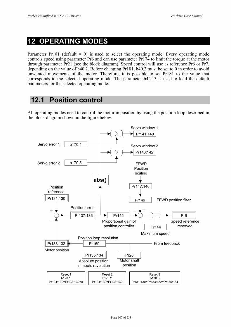
Parker Hannifin S.p.A S.B.C. Division Hi-drive User Manual
Page 107 of 233
12 OPERATING MODES Parameter Pr181 (default = 0) is used to select the operating mode. Every operating mode controls speed using parameter Pr6 and can use parameter Pr174 to limit the torque at the motor through parameter Pr21 (see the block diagram). Speed control will use as reference Pr6 or Pr7, depending on the value of b40.2. Before changing Pr181, b40.2 must be set to 0 in order to avoid unwanted movements of the motor. Therefore, it is possible to set Pr181 to the value that corresponds to the selected operating mode. The parameter b42.13 is used to load the default parameters for the selected operating mode.
12.1 Position control All operating modes need to control the motor in position by using the position loop described in the block diagram shown in the figure below.
abs()
From feedback
Pr28 Pr135:134
Pr169
Pr144
Pr145 Pr6
Pr149
b170.5
b170.4
Pr133:132
Pr131:130
Pr137:136
Pr147:146
Pr141:140
Pr143:142
Motor shaftposition
Absolute positionin mech. revolution
Motor position
Maximum speed
Positionreference
Position error
Proportional gain of position controller
Speed referencereserved
FFWD position filter
FFWDPositionscaling
Servo error 2
Servo error 1 Servo window 2
Servo window 1
Position loop resolution
Reset 1b170.1
Pr131:130=Pr133:132=0
Reset 2b170.2
Pr131:130=Pr133:132
Reset 3b170.3
Pr131:130=Pr133:132=Pr135:134
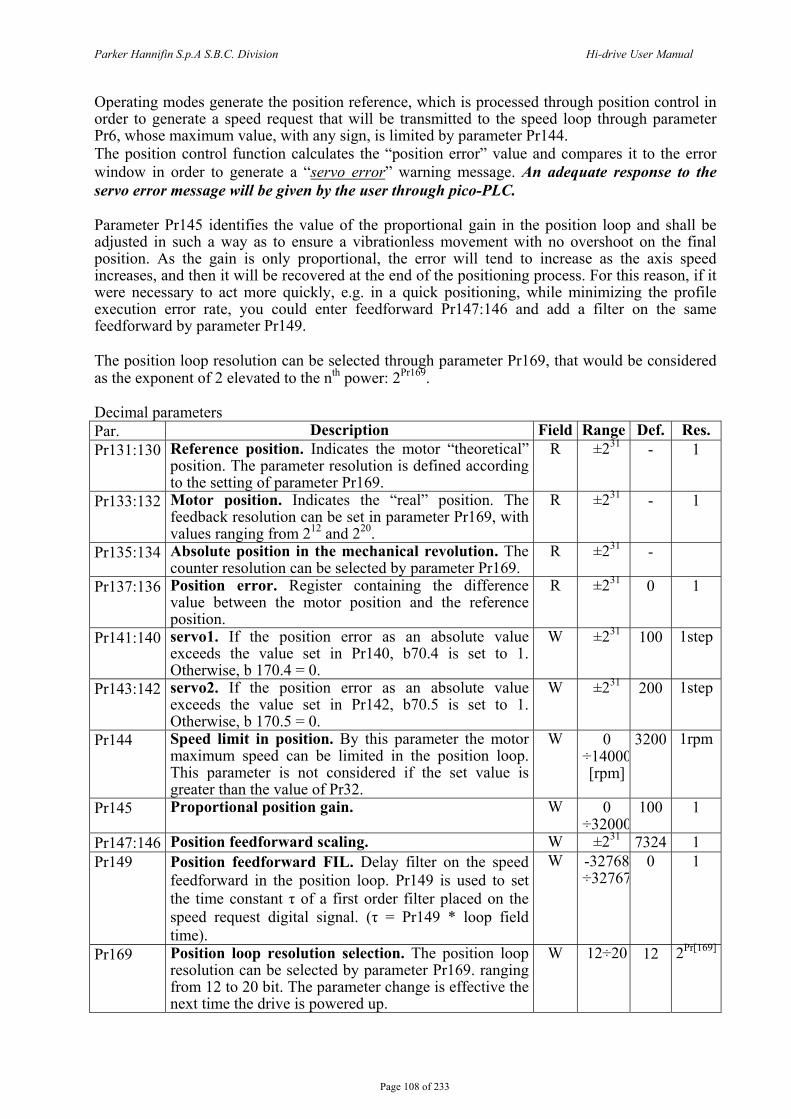
Parker Hannifin S.p.A S.B.C. Division Hi-drive User Manual
Page 108 of 233
Operating modes generate the position reference, which is processed through position control in order to generate a speed request that will be transmitted to the speed loop through parameter Pr6, whose maximum value, with any sign, is limited by parameter Pr144. The position control function calculates the “position error” value and compares it to the error window in order to generate a “servo error” warning message. An adequate response to the servo error message will be given by the user through pico-PLC. Parameter Pr145 identifies the value of the proportional gain in the position loop and shall be adjusted in such a way as to ensure a vibrationless movement with no overshoot on the final position. As the gain is only proportional, the error will tend to increase as the axis speed increases, and then it will be recovered at the end of the positioning process. For this reason, if it were necessary to act more quickly, e.g. in a quick positioning, while minimizing the profile execution error rate, you could enter feedforward Pr147:146 and add a filter on the same feedforward by parameter Pr149. The position loop resolution can be selected through parameter Pr169, that would be considered as the exponent of 2 elevated to the nth power: 2Pr169. Decimal parameters Par. Description Field Range Def. Res. Pr131:130 Reference position. Indicates the motor “theoretical”
position. The parameter resolution is defined according to the setting of parameter Pr169.
R ±231 - 1
Pr133:132 Motor position. Indicates the “real” position. The feedback resolution can be set in parameter Pr169, with values ranging from 212 and 220.
R ±231 - 1
Pr135:134 Absolute position in the mechanical revolution. The counter resolution can be selected by parameter Pr169.
R ±231 -
Pr137:136 Position error. Register containing the difference value between the motor position and the reference position.
R ±231 0 1
Pr141:140 servo1. If the position error as an absolute value exceeds the value set in Pr140, b70.4 is set to 1. Otherwise, b 170.4 = 0.
W ±231 100 1step
Pr143:142 servo2. If the position error as an absolute value exceeds the value set in Pr142, b70.5 is set to 1. Otherwise, b 170.5 = 0.
W ±231 200 1step
Pr144 Speed limit in position. By this parameter the motor maximum speed can be limited in the position loop. This parameter is not considered if the set value is greater than the value of Pr32.
W 0 ÷14000[rpm]
3200
1rpm
Pr145 Proportional position gain. W 0 ÷32000
100 1
Pr147:146 Position feedforward scaling. W ±231 7324 1 Pr149 Position feedforward FIL. Delay filter on the speed
feedforward in the position loop. Pr149 is used to set the time constant τ of a first order filter placed on the speed request digital signal. (τ = Pr149 * loop field time).
W -32768 ÷32767
0 1
Pr169 Position loop resolution selection. The position loop resolution can be selected by parameter Pr169. ranging from 12 to 20 bit. The parameter change is effective the next time the drive is powered up.
W 12÷20 12 2Pr[169]

Parker Hannifin S.p.A S.B.C. Division Hi-drive User Manual
Page 109 of 233
Binary parameters Par. Description Field Def. b170.0 Feedback direction. When the bit is set to 1, the motor
rotation is inverted. W 0
b170.1 Reset 1. Reset command type 1: this is used to reset the position reference counters and the motor reference counters. Self resetting
W 0
b170.2 Reset 2. Reset command type 2: the position reference counter, Pr130:131 (“theoretical” position), gets the same value as the motor “real” position Pr132:133. Self resetting.
W 0
b170.3 Reset 3. Reset command type 3.(Pr212:213=Pr2. Self resetting
W 0
b170.4 Servo error 1. b170.4 will be set to 1 if the position error as an absolute value exceeds the value set in Pr140.
R 0
b170.5 Servo error 2. b170.5 will be set to 1 if the position error as an absolute value exceeds the value set in Pr142.
R 0
b170.14 Position loop feedback selection. Position loop feedback selection bit **
W 0
b170.15 Position loop feedback selection. Position loop feedback selection bit **
W 0
** b170.15 b170.14 FBK A 0 0 FBK B 0 1 FBK C 1 0 Reserved (“00” automatic reset) 1 1
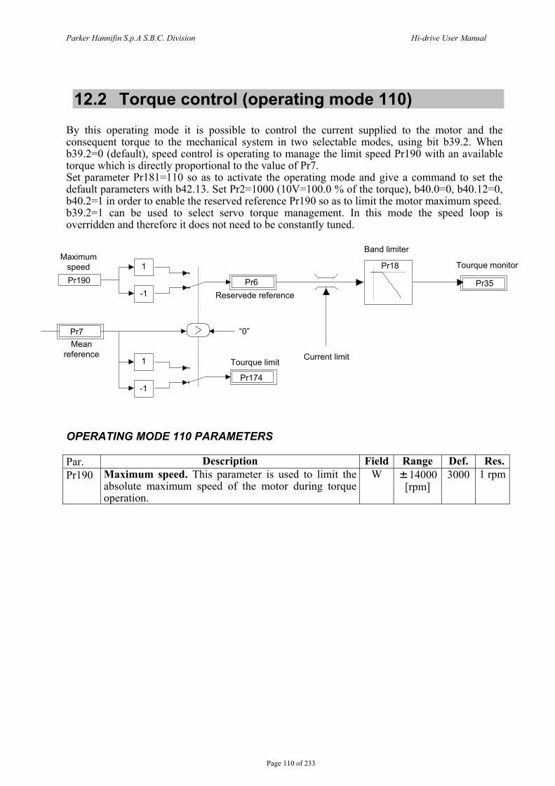
Parker Hannifin S.p.A S.B.C. Division Hi-drive User Manual
Page 110 of 233
12.2 Torque control (operating mode 110) By this operating mode it is possible to control the current supplied to the motor and the consequent torque to the mechanical system in two selectable modes, using bit b39.2. When b39.2=0 (default), speed control is operating to manage the limit speed Pr190 with an available torque which is directly proportional to the value of Pr7. Set parameter Pr181=110 so as to activate the operating mode and give a command to set the default parameters with b42.13. Set Pr2=1000 (10V=100.0 % of the torque), b40.0=0, b40.12=0, b40.2=1 in order to enable the reserved reference Pr190 so as to limit the motor maximum speed. b39.2=1 can be used to select servo torque management. In this mode the speed loop is overridden and therefore it does not need to be constantly tuned.
1
-1
1
-1
Pr190
Pr7
Pr6
Pr174
Current limit
Pr18
Pr35Reservede reference
“0”
Tourque limit
Mean reference
Maximum speed
Band limiter
Tourque monitor
OPERATING MODE 110 PARAMETERS Par. Description Field Range Def. Res.Pr190 Maximum speed. This parameter is used to limit the
absolute maximum speed of the motor during torque operation.
W 14000 [rpm]
3000 1 rpm
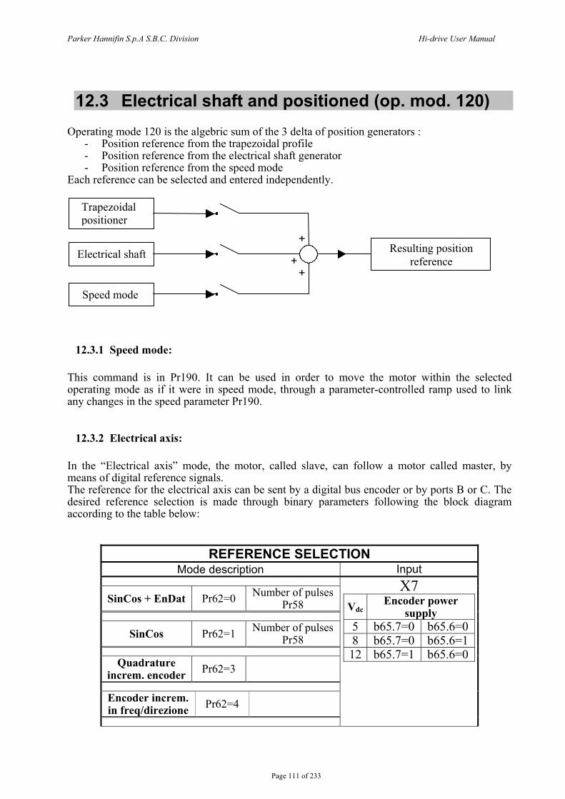
Parker Hannifin S.p.A S.B.C. Division Hi-drive User Manual
Page 111 of 233
12.3 Electrical shaft and positioned (op. mod. 120) Operating mode 120 is the algebric sum of the 3 delta of position generators :
- Position reference from the trapezoidal profile - Position reference from the electrical shaft generator - Position reference from the speed mode
Each reference can be selected and entered independently.
+
+ +
12.3.1 Speed mode: This command is in Pr190. It can be used in order to move the motor within the selected operating mode as if it were in speed mode, through a parameter-controlled ramp used to link any changes in the speed parameter Pr190.
12.3.2 Electrical axis: In the “Electrical axis” mode, the motor, called slave, can follow a motor called master, by means of digital reference signals. The reference for the electrical axis can be sent by a digital bus encoder or by ports B or C. The desired reference selection is made through binary parameters following the block diagram according to the table below:
REFERENCE SELECTION Mode description Input
SinCos + EnDat Pr62=0 Number of pulses Pr58
SinCos Pr62=1 Number of pulses Pr58
Quadrature
increm. encoder Pr62=3
Encoder increm. in freq/direzione Pr62=4
X7 Vdc
Encoder power supply
5 b65.7=0 b65.6=0 8 b65.7=0 b65.6=1
12 b65.7=1 b65.6=0
Trapezoidal positioner
Electrical shaft
Speed mode
Resulting position reference
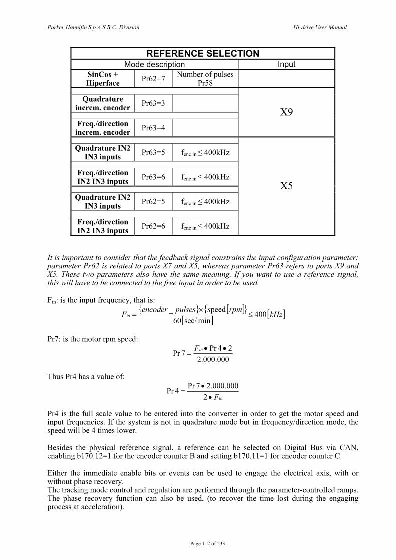
Parker Hannifin S.p.A S.B.C. Division Hi-drive User Manual
Page 112 of 233
REFERENCE SELECTION Mode description Input
SinCos + Hiperface Pr62=7 Number of pulses
Pr58
Quadrature increm. encoder Pr63=3
Freq./direction increm. encoder Pr63=4
X9
Quadrature IN2
IN3 inputs Pr63=5 fenc in ≤ 400kHz
Freq./direction IN2 IN3 inputs Pr63=6 fenc in ≤ 400kHz
Quadrature IN2
IN3 inputs Pr62=5 fenc in ≤ 400kHz
Freq./direction IN2 IN3 inputs Pr62=6 fenc in ≤ 400kHz
X5
It is important to consider that the feedback signal constrains the input configuration parameter: parameter Pr62 is related to ports X7 and X5, whereas parameter Pr63 refers to ports X9 and X5. These two parameters also have the same meaning. If you want to use a reference signal, this will have to be connected to the free input in order to be used. Fin: is the input frequency, that is:
[ ] [ ] [ ]kHzrpmspulsesencoderFin 400
minsec/ 60 peed_
≤×
=
Pr7: is the motor rpm speed:
000.000.22 4Pr 7Pr ••
=inF
Thus Pr4 has a value of:
inF2000.000.2 7Pr4Pr
••
=
Pr4 is the full scale value to be entered into the converter in order to get the motor speed and input frequencies. If the system is not in quadrature mode but in frequency/direction mode, the speed will be 4 times lower. Besides the physical reference signal, a reference can be selected on Digital Bus via CAN, enabling b170.12=1 for the encoder counter B and setting b170.11=1 for encoder counter C. Either the immediate enable bits or events can be used to engage the electrical axis, with or without phase recovery. The tracking mode control and regulation are performed through the parameter-controlled ramps. The phase recovery function can also be used, (to recover the time lost during the engaging process at acceleration).
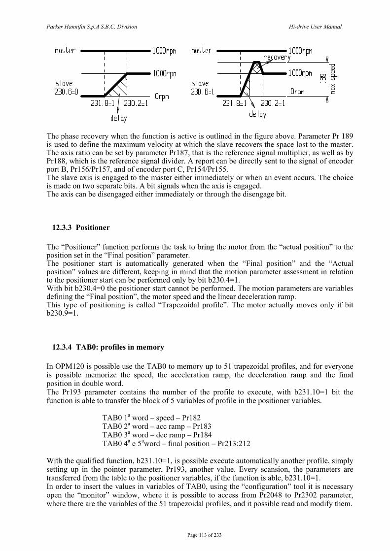
Parker Hannifin S.p.A S.B.C. Division Hi-drive User Manual
Page 113 of 233
The phase recovery when the function is active is outlined in the figure above. Parameter Pr 189 is used to define the maximum velocity at which the slave recovers the space lost to the master. The axis ratio can be set by parameter Pr187, that is the reference signal multiplier, as well as by Pr188, which is the reference signal divider. A report can be directly sent to the signal of encoder port B, Pr156/Pr157, and of encoder port C, Pr154/Pr155. The slave axis is engaged to the master either immediately or when an event occurs. The choice is made on two separate bits. A bit signals when the axis is engaged. The axis can be disengaged either immediately or through the disengage bit.
12.3.3 Positioner The “Positioner” function performs the task to bring the motor from the “actual position” to the position set in the “Final position” parameter. The positioner start is automatically generated when the “Final position” and the “Actual position” values are different, keeping in mind that the motion parameter assessment in relation to the positioner start can be performed only by bit b230.4=1. With bit b230.4=0 the positioner start cannot be performed. The motion parameters are variables defining the “Final position”, the motor speed and the linear deceleration ramp. This type of positioning is called “Trapezoidal profile”. The motor actually moves only if bit b230.9=1.
12.3.4 TAB0: profiles in memory In OPM120 is possible use the TAB0 to memory up to 51 trapezoidal profiles, and for everyone is possible memorize the speed, the acceleration ramp, the deceleration ramp and the final position in double word. The Pr193 parameter contains the number of the profile to execute, with b231.10=1 bit the function is able to transfer the block of 5 variables of profile in the positioner variables. TAB0 1a word – speed – Pr182
TAB0 2a word – acc ramp – Pr183 TAB0 3a word – dec ramp – Pr184 TAB0 4a e 5aword – final position – Pr213:212
With the qualified function, b231.10=1, is possible execute automatically another profile, simply setting up in the pointer parameter, Pr193, another value. Every scansion, the parameters are transferred from the table to the positioner variables, if the function is able, b231.10=1. In order to insert the values in variables of TAB0, using the “configuration” tool it is necessary open the “monitor” window, where it is possible to access from Pr2048 to Pr2302 parameter, where there are the variables of the 51 trapezoidal profiles, and it possible read and modify them.
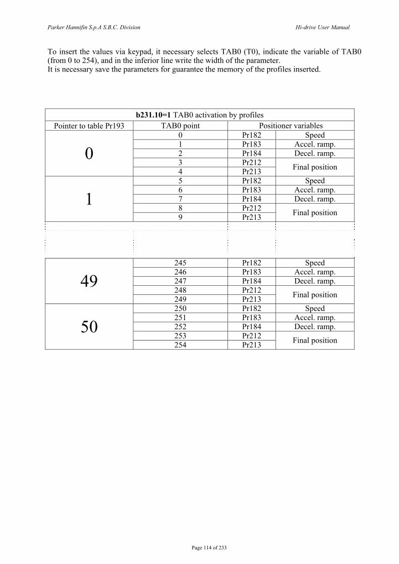
Parker Hannifin S.p.A S.B.C. Division Hi-drive User Manual
Page 114 of 233
To insert the values via keypad, it necessary selects TAB0 (T0), indicate the variable of TAB0 (from 0 to 254), and in the inferior line write the width of the parameter. It is necessary save the parameters for guarantee the memory of the profiles inserted.
b231.10=1 TAB0 activation by profiles Pointer to table Pr193 TAB0 point Positioner variables
0 Pr182 Speed 1 Pr183 Accel. ramp. 2 Pr184 Decel. ramp. 3 Pr212
0 4 Pr213 Final position
5 Pr182 Speed 6 Pr183 Accel. ramp. 7 Pr184 Decel. ramp. 8 Pr212
1
9 Pr213 Final position
245 Pr182 Speed 246 Pr183 Accel. ramp. 247 Pr184 Decel. ramp. 248 Pr212
49
249 Pr213 Final position
250 Pr182 Speed 251 Pr183 Accel. ramp. 252 Pr184 Decel. ramp. 253 Pr212
50 254 Pr213 Final position
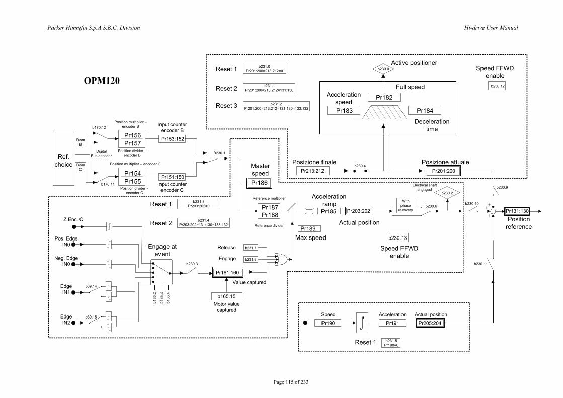
Parker Hannifin S.p.A S.B.C. Division Hi-drive User Manual
Page 115 of 233
Ref. choice
Pr156Pr157
Pr154Pr155
Pr153:152
Pr186
Pr187Pr188
b170.12
Engage at event
Z Enc. C
Pr151:150b170.11
B230.1
b39.14
b39.15
b230.3
Pr161:160
b165.15
b231.8
b231.7
Pr189
Pr185 Pr203:202
b230.13
b230.10
b230.11
b230.9b230.2
b230.6
Pr190 Pr191 Pr205:204
Pr131:130
With phase
recovery
Pr201:200Pr213:212
Pr183 Pr184
Pr182
b230.0
b230.4
Speed Acceleration Actual position
Position reference
Posizione attuale
Speed FFWDenable
Actual position
Accelerationramp
Posizione finale
Deceleration time
Acceleration speed
Full speed
Active positioner
b230.12
Electrical shaft engaged
Max speed
Speed FFWD enable
Reference multiplier
Reference divider
Release
Engage
Value captured
Motor value captured
Input counter encoder B
Position multiplier – encoder C
Position divider - encoder B
Master speed
Pos. Edge IN0
Neg. Edge IN0
Edge IN1
Edge IN2
DigitalBus encoder
FromB
FromC
b231.0Pr201:200=213:212=0
b231.1Pr201:200=213:212=131:130
b231.2Pr201:200=213:212=131:130=133:132
Reset 1
Reset 2
Reset 3
b231.3Pr203:202=0
b231.4Pr203:202=131:130=133:132
Reset 1
Reset 2
b231.5Pr190=0Reset 1
b165
.2
b165
.3
b165
.4
Position divider - encoder C
Position multiplier –encoder B
Input counter encoder C
OPM120
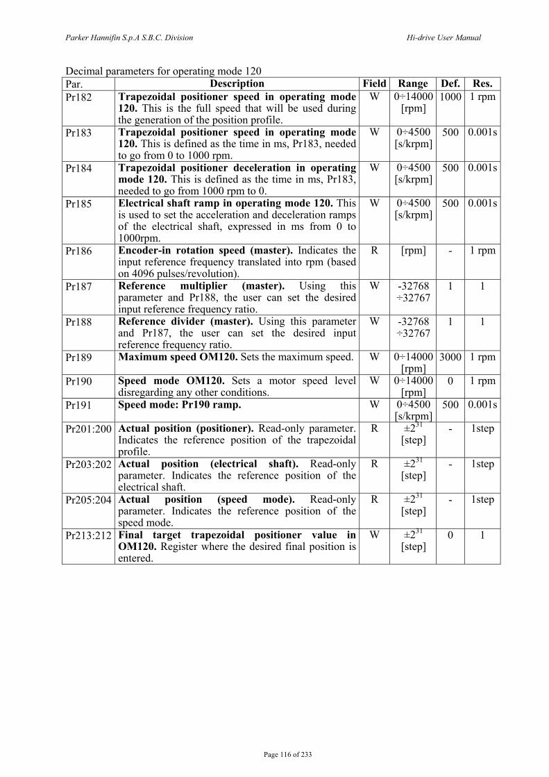
Parker Hannifin S.p.A S.B.C. Division Hi-drive User Manual
Page 116 of 233
Decimal parameters for operating mode 120 Par. Description Field Range Def. Res. Pr182 Trapezoidal positioner speed in operating mode
120. This is the full speed that will be used during the generation of the position profile.
W 0÷14000 [rpm]
1000 1 rpm
Pr183 Trapezoidal positioner speed in operating mode 120. This is defined as the time in ms, Pr183, needed to go from 0 to 1000 rpm.
W 0÷4500 [s/krpm]
500 0.001s
Pr184 Trapezoidal positioner deceleration in operating mode 120. This is defined as the time in ms, Pr183, needed to go from 1000 rpm to 0.
W 0÷4500 [s/krpm]
500 0.001s
Pr185 Electrical shaft ramp in operating mode 120. This is used to set the acceleration and deceleration ramps of the electrical shaft, expressed in ms from 0 to 1000rpm.
W 0÷4500 [s/krpm]
500 0.001s
Pr186 Encoder-in rotation speed (master). Indicates the input reference frequency translated into rpm (based on 4096 pulses/revolution).
R [rpm] - 1 rpm
Pr187 Reference multiplier (master). Using this parameter and Pr188, the user can set the desired input reference frequency ratio.
W -32768 ÷32767
1 1
Pr188 Reference divider (master). Using this parameter and Pr187, the user can set the desired input reference frequency ratio.
W -32768 ÷32767
1 1
Pr189 Maximum speed OM120. Sets the maximum speed. W 0÷14000 [rpm]
3000 1 rpm
Pr190 Speed mode OM120. Sets a motor speed level disregarding any other conditions.
W 0÷14000 [rpm]
0 1 rpm
Pr191 Speed mode: Pr190 ramp. W 0÷4500 [s/krpm]
500 0.001s
Pr201:200 Actual position (positioner). Read-only parameter. Indicates the reference position of the trapezoidal profile.
R ±231 [step]
- 1step
Pr203:202 Actual position (electrical shaft). Read-only parameter. Indicates the reference position of the electrical shaft.
R ±231 [step]
- 1step
Pr205:204 Actual position (speed mode). Read-only parameter. Indicates the reference position of the speed mode.
R ±231 [step]
- 1step
Pr213:212 Final target trapezoidal positioner value in OM120. Register where the desired final position is entered.
W ±231 [step]
0 1
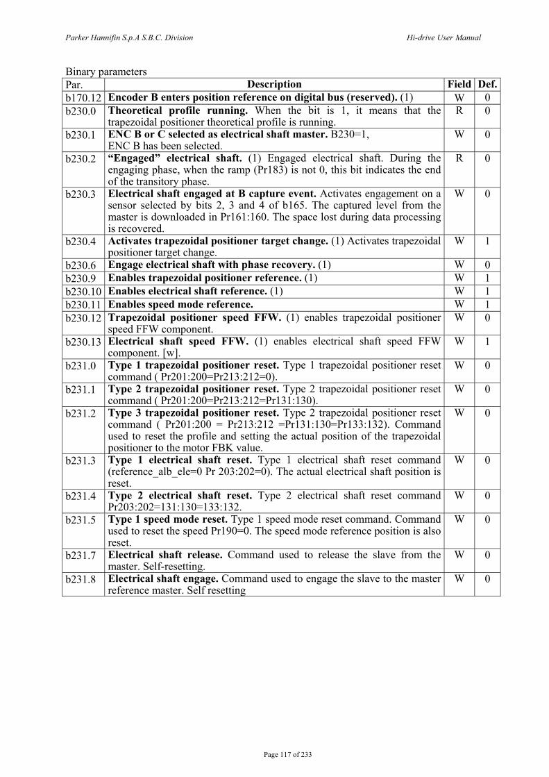
Parker Hannifin S.p.A S.B.C. Division Hi-drive User Manual
Page 117 of 233
Binary parameters Par. Description Field Def.b170.12 Encoder B enters position reference on digital bus (reserved). (1) W 0 b230.0 Theoretical profile running. When the bit is 1, it means that the
trapezoidal positioner theoretical profile is running. R 0
b230.1 ENC B or C selected as electrical shaft master. B230=1, ENC B has been selected.
W 0
b230.2 “Engaged” electrical shaft. (1) Engaged electrical shaft. During the engaging phase, when the ramp (Pr183) is not 0, this bit indicates the end of the transitory phase.
R 0
b230.3 Electrical shaft engaged at B capture event. Activates engagement on a sensor selected by bits 2, 3 and 4 of b165. The captured level from the master is downloaded in Pr161:160. The space lost during data processing is recovered.
W 0
b230.4 Activates trapezoidal positioner target change. (1) Activates trapezoidal positioner target change.
W 1
b230.6 Engage electrical shaft with phase recovery. (1) W 0 b230.9 Enables trapezoidal positioner reference. (1) W 1 b230.10 Enables electrical shaft reference. (1) W 1 b230.11 Enables speed mode reference. W 1 b230.12 Trapezoidal positioner speed FFW. (1) enables trapezoidal positioner
speed FFW component. W 0
b230.13 Electrical shaft speed FFW. (1) enables electrical shaft speed FFW component. [w].
W 1
b231.0 Type 1 trapezoidal positioner reset. Type 1 trapezoidal positioner reset command ( Pr201:200=Pr213:212=0).
W 0
b231.1 Type 2 trapezoidal positioner reset. Type 2 trapezoidal positioner reset command ( Pr201:200=Pr213:212=Pr131:130).
W 0
b231.2 Type 3 trapezoidal positioner reset. Type 2 trapezoidal positioner reset command ( Pr201:200 = Pr213:212 =Pr131:130=Pr133:132). Command used to reset the profile and setting the actual position of the trapezoidal positioner to the motor FBK value.
W 0
b231.3 Type 1 electrical shaft reset. Type 1 electrical shaft reset command (reference_alb_ele=0 Pr 203:202=0). The actual electrical shaft position is reset.
W 0
b231.4 Type 2 electrical shaft reset. Type 2 electrical shaft reset command Pr203:202=131:130=133:132.
W 0
b231.5 Type 1 speed mode reset. Type 1 speed mode reset command. Command used to reset the speed Pr190=0. The speed mode reference position is also reset.
W 0
b231.7 Electrical shaft release. Command used to release the slave from the master. Self-resetting.
W 0
b231.8 Electrical shaft engage. Command used to engage the slave to the master reference master. Self resetting
W 0
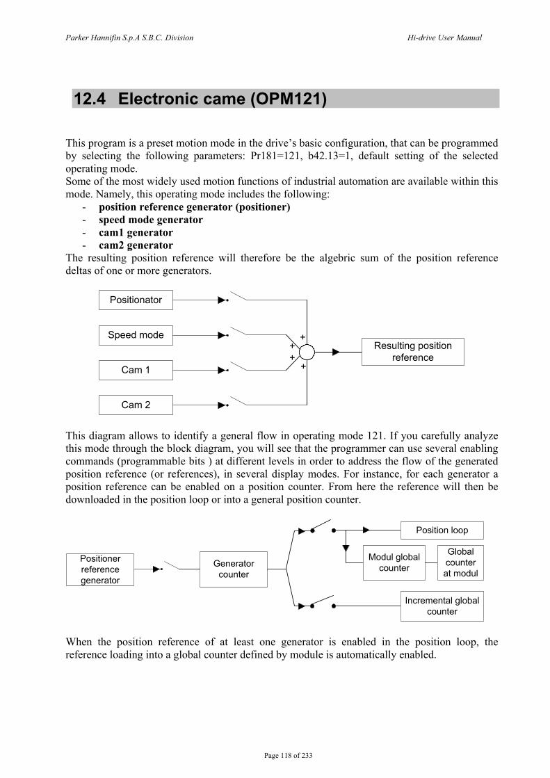
Parker Hannifin S.p.A S.B.C. Division Hi-drive User Manual
Page 118 of 233
12.4 Electronic came (OPM121) This program is a preset motion mode in the drive’s basic configuration, that can be programmed by selecting the following parameters: Pr181=121, b42.13=1, default setting of the selected operating mode. Some of the most widely used motion functions of industrial automation are available within this mode. Namely, this operating mode includes the following:
- position reference generator (positioner) - speed mode generator - cam1 generator - cam2 generator
The resulting position reference will therefore be the algebric sum of the position reference deltas of one or more generators.
Positionator
Speed mode
Cam 1
Cam 2
Resulting position reference
+++
+
This diagram allows to identify a general flow in operating mode 121. If you carefully analyze this mode through the block diagram, you will see that the programmer can use several enabling commands (programmable bits ) at different levels in order to address the flow of the generated position reference (or references), in several display modes. For instance, for each generator a position reference can be enabled on a position counter. From here the reference will then be downloaded in the position loop or into a general position counter.
Positioner reference generator
Generator counter
Position loop
Incremental global counter
Modul global counter
Global counter at modul
When the position reference of at least one generator is enabled in the position loop, the reference loading into a global counter defined by module is automatically enabled.
Parker Hannifin S.p.A S.B.C. Division Hi-drive User Manual
Page 119 of 233
12.4.1 Posizionator This is a trapezoidal profile generator, with the following user-definable parameters:
- speed profile - acceleration - deceleration - final value in motor step
The parameters referred to the positioner levels, final position Pr211: 210 and actual position Pr201:200, are absolute. However, they are subsequently transferred to the other adjustment parameters following the block diagram.
The thus position reference generated in this way is loaded into the position loop as well as in the global counter. The generated reference, activated through a bit command, is then loaded as an addition to the master in both generators CAM1 and CAM2.
12.4.2 Speed mode This is a position generator, but it is set as a speed reference. The following parameters will have to be set:
Rpm speed acceleration
12.4.3 CAM1 and CAM2 The two CAM generators are specifically designed to meet the requirements of automatic machines using electronic cams. Four tables are available, namely TAB0, TAB1, TAB2 and TAB3, that have been implemented to perform a series of cam functions. Each table is described by a vector made of 257 elements, that indicate the position to be taken by the controlled axis when the motor axis is in the position:
256modulmaster numberelement function slave •
=
In each table the value of the vector elements is ranging between 0 and 9999, whereas 10,000 shall be the count number set in the slave module parameter. In order to generate a table, the axis route must be divided into 257 points; the value of each point will have to be rated to 10000, because this is the maximum value that can be written in the table elements. The 257th element of each table defines the cam as closed if it is = 0, or as open if it is = 10,000. The motion will be able to perform the points listed in the table; if the required speed and torque are within the motor’s electric limits (Maximum Speed and Torque). Through a series of parameters it is possible to automatically program one of the motion laws that have been set in the drive in one of the four tables. Functions can be retrieved as follows:
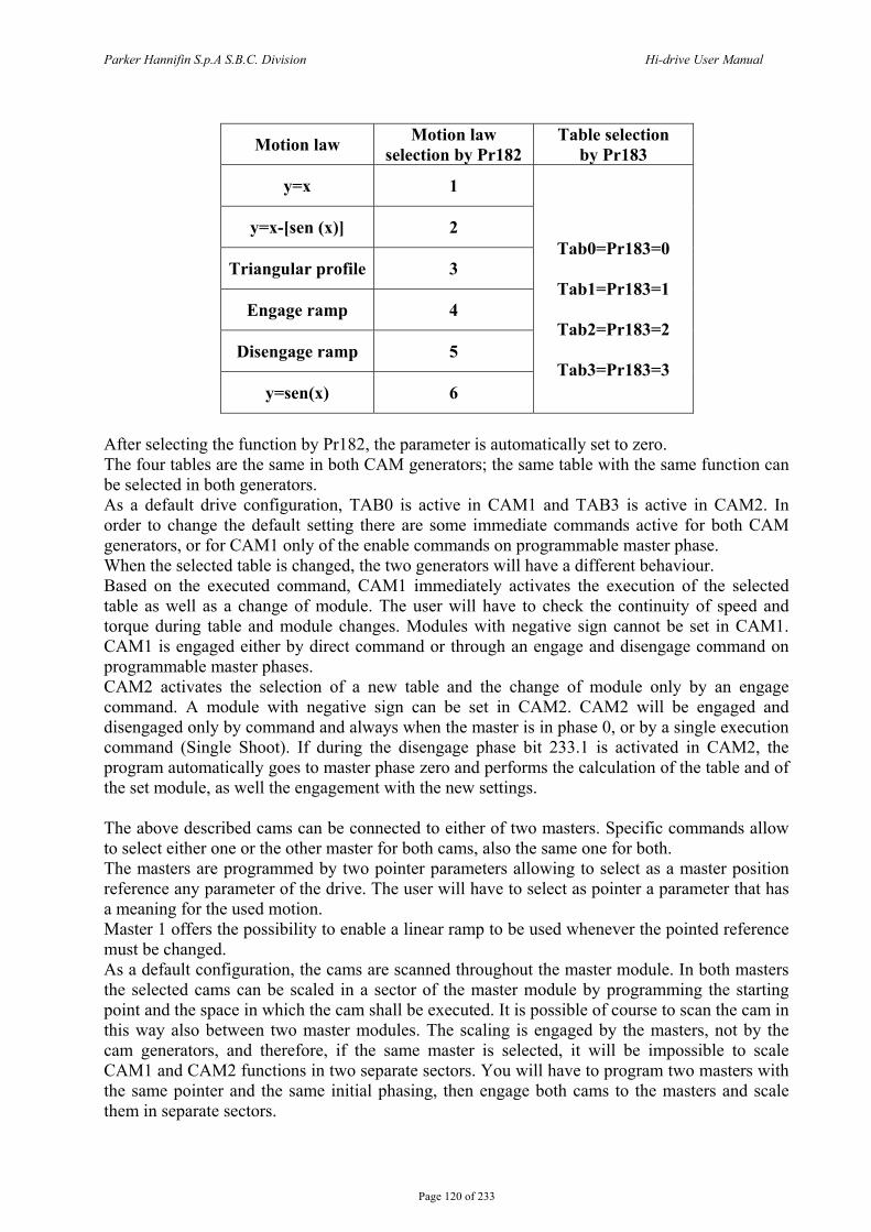
Parker Hannifin S.p.A S.B.C. Division Hi-drive User Manual
Page 120 of 233
Motion law Motion law
selection by Pr182 Table selection
by Pr183
y=x 1
y=x-[sen (x)] 2
Triangular profile 3
Engage ramp 4
Disengage ramp 5
y=sen(x) 6
Tab0=Pr183=0
Tab1=Pr183=1
Tab2=Pr183=2
Tab3=Pr183=3
After selecting the function by Pr182, the parameter is automatically set to zero. The four tables are the same in both CAM generators; the same table with the same function can be selected in both generators. As a default drive configuration, TAB0 is active in CAM1 and TAB3 is active in CAM2. In order to change the default setting there are some immediate commands active for both CAM generators, or for CAM1 only of the enable commands on programmable master phase. When the selected table is changed, the two generators will have a different behaviour. Based on the executed command, CAM1 immediately activates the execution of the selected table as well as a change of module. The user will have to check the continuity of speed and torque during table and module changes. Modules with negative sign cannot be set in CAM1. CAM1 is engaged either by direct command or through an engage and disengage command on programmable master phases. CAM2 activates the selection of a new table and the change of module only by an engage command. A module with negative sign can be set in CAM2. CAM2 will be engaged and disengaged only by command and always when the master is in phase 0, or by a single execution command (Single Shoot). If during the disengage phase bit 233.1 is activated in CAM2, the program automatically goes to master phase zero and performs the calculation of the table and of the set module, as well the engagement with the new settings. The above described cams can be connected to either of two masters. Specific commands allow to select either one or the other master for both cams, also the same one for both. The masters are programmed by two pointer parameters allowing to select as a master position reference any parameter of the drive. The user will have to select as pointer a parameter that has a meaning for the used motion. Master 1 offers the possibility to enable a linear ramp to be used whenever the pointed reference must be changed. As a default configuration, the cams are scanned throughout the master module. In both masters the selected cams can be scaled in a sector of the master module by programming the starting point and the space in which the cam shall be executed. It is possible of course to scan the cam in this way also between two master modules. The scaling is engaged by the masters, not by the cam generators, and therefore, if the same master is selected, it will be impossible to scale CAM1 and CAM2 functions in two separate sectors. You will have to program two masters with the same pointer and the same initial phasing, then engage both cams to the masters and scale them in separate sectors.
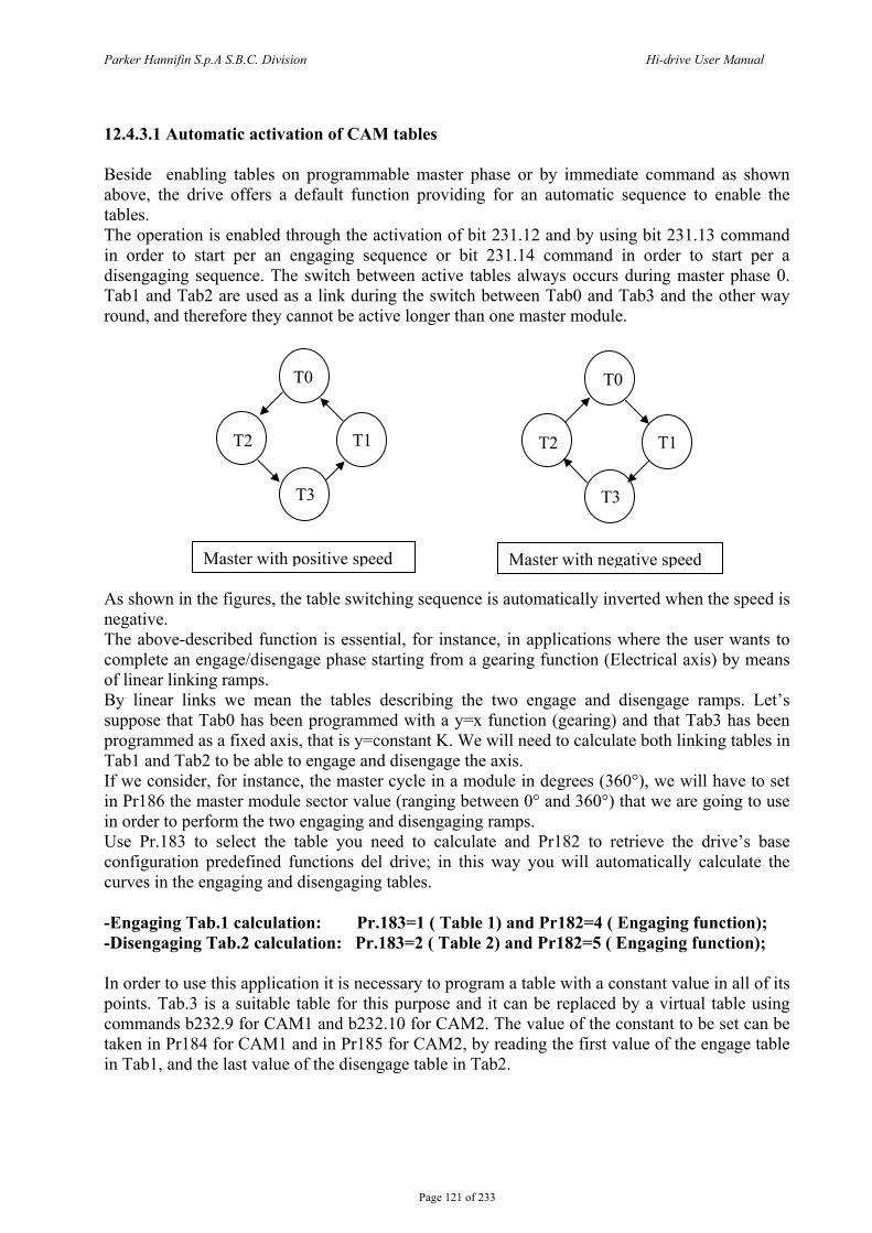
Parker Hannifin S.p.A S.B.C. Division Hi-drive User Manual
Page 121 of 233
12.4.3.1 Automatic activation of CAM tables Beside enabling tables on programmable master phase or by immediate command as shown above, the drive offers a default function providing for an automatic sequence to enable the tables. The operation is enabled through the activation of bit 231.12 and by using bit 231.13 command in order to start per an engaging sequence or bit 231.14 command in order to start per a disengaging sequence. The switch between active tables always occurs during master phase 0. Tab1 and Tab2 are used as a link during the switch between Tab0 and Tab3 and the other way round, and therefore they cannot be active longer than one master module. As shown in the figures, the table switching sequence is automatically inverted when the speed is negative. The above-described function is essential, for instance, in applications where the user wants to complete an engage/disengage phase starting from a gearing function (Electrical axis) by means of linear linking ramps. By linear links we mean the tables describing the two engage and disengage ramps. Let’s suppose that Tab0 has been programmed with a y=x function (gearing) and that Tab3 has been programmed as a fixed axis, that is y=constant K. We will need to calculate both linking tables in Tab1 and Tab2 to be able to engage and disengage the axis. If we consider, for instance, the master cycle in a module in degrees (360°), we will have to set in Pr186 the master module sector value (ranging between 0° and 360°) that we are going to use in order to perform the two engaging and disengaging ramps. Use Pr.183 to select the table you need to calculate and Pr182 to retrieve the drive’s base configuration predefined functions del drive; in this way you will automatically calculate the curves in the engaging and disengaging tables. -Engaging Tab.1 calculation: Pr.183=1 ( Table 1) and Pr182=4 ( Engaging function); -Disengaging Tab.2 calculation: Pr.183=2 ( Table 2) and Pr182=5 ( Engaging function); In order to use this application it is necessary to program a table with a constant value in all of its points. Tab.3 is a suitable table for this purpose and it can be replaced by a virtual table using commands b232.9 for CAM1 and b232.10 for CAM2. The value of the constant to be set can be taken in Pr184 for CAM1 and in Pr185 for CAM2, by reading the first value of the engage table in Tab1, and the last value of the disengage table in Tab2.
Master with positive speed Master with negative speed
T0
T2 T1
T3
T0
T2 T1
T3
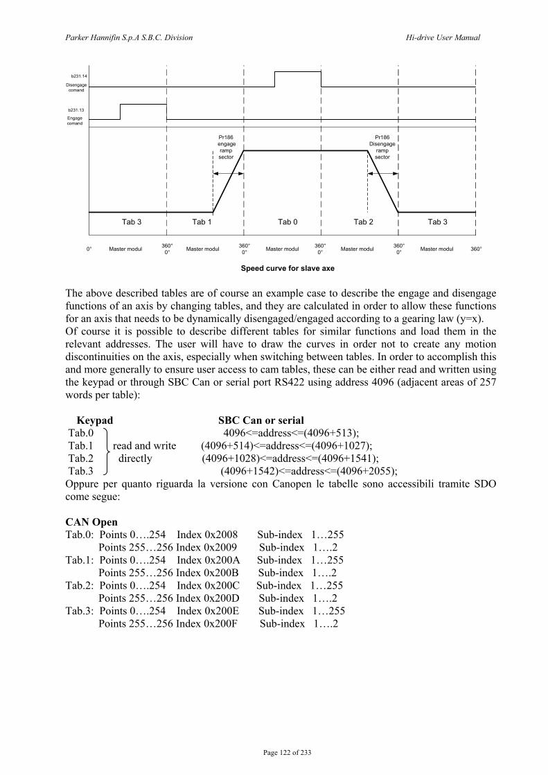
Parker Hannifin S.p.A S.B.C. Division Hi-drive User Manual
Page 122 of 233
Master modul Master modul Master modul Master modul Master modul
Tab 3 Tab 1 Tab 0 Tab 2 Tab 3
0° 360°0°
360°0°
360°0°
360°0° 360°
Pr186 engage
ramp sector
Pr186Disengage
ramp sector
b231.13
b231.14
Speed curve for slave axe
Engagecomand
Disengagecomand
The above described tables are of course an example case to describe the engage and disengage functions of an axis by changing tables, and they are calculated in order to allow these functions for an axis that needs to be dynamically disengaged/engaged according to a gearing law (y=x). Of course it is possible to describe different tables for similar functions and load them in the relevant addresses. The user will have to draw the curves in order not to create any motion discontinuities on the axis, especially when switching between tables. In order to accomplish this and more generally to ensure user access to cam tables, these can be either read and written using the keypad or through SBC Can or serial port RS422 using address 4096 (adjacent areas of 257 words per table): Keypad SBC Can or serial Tab.0 4096<=address<=(4096+513); Tab.1 read and write (4096+514)<=address<=(4096+1027); Tab.2 directly (4096+1028)<=address<=(4096+1541); Tab.3 (4096+1542)<=address<=(4096+2055); Oppure per quanto riguarda la versione con Canopen le tabelle sono accessibili tramite SDO come segue: CAN Open Tab.0: Points 0….254 Index 0x2008 Sub-index 1…255 Points 255…256 Index 0x2009 Sub-index 1….2 Tab.1: Points 0….254 Index 0x200A Sub-index 1…255 Points 255…256 Index 0x200B Sub-index 1….2 Tab.2: Points 0….254 Index 0x200C Sub-index 1…255 Points 255…256 Index 0x200D Sub-index 1….2 Tab.3: Points 0….254 Index 0x200E Sub-index 1…255 Points 255…256 Index 0x200F Sub-index 1….2
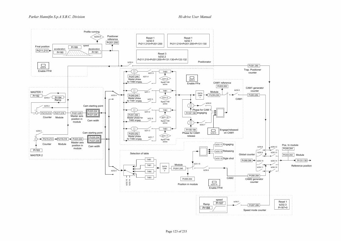
Parker Hannifin S.p.A S.B.C. Division Hi-drive User Manual
Page 123 of 233
Pr213:212
b230.3
b230.0
b230.2
TAB0
TAB1
TAB2
TAB3
Pr247:246
b231.0
b231.4
b231.1
b231.5
b231.2
b231.6
b231.7
b231.3
b231.8
b231.9
b231.10
b231.11
DATACAM
1
Pr197:196
Pr199:198
Pr239:238
Pr203:202
b230.5
Pr283:282
Pr281:280
Pr285:284
Pr287:286
Pr289:288
Pr245:244
Pr243:242
Pr131:130
b232
.15
b232
.14
TAB0
TAB1
TAB2
TAB3
DATACAM
2
b230.8
b230.9
b230.10
b230.11
b230.12
b230.13
b230.14
b230.15
b230.6
b232.11
b232.12
Pr241:240
Pr205:204
b230.7Pr187
Pr188
Counter Module
Ramp
Master axis position in
module
Counter Module Master axis position in
module
Selection of table
Module
Position in module
Ramp
speed
b231.15
CAM2
Engaging
Releasing
Sigle shot
Positionator
CAM1
Pos. In module
Module
b232.6
b232.7
Module
Phase for CAM1 release
CAM1 reference
MASTER 1
MASTER 2
Pr211:210
Pr201:200
Pr189
Pr190 Pr191
b233.0
b230.4
Profile running
Positioner reference
Final positionacceleration
speeddeceleration
Pr194Pr192
Pr217:216 Pr221:220
Pr193
Pr215:214 Pr219:218 Pr223:222
b232.4
b232.5
Engage/released on CAM1b232.8
Pr249:248
Pr251:250
Pr253:252
Reset 1b232.0
Pr211:210=Pr201:200
Pr225:224Pr227:226
Cam starting point
Cam width
Cam starting point
Cam width
Pr235:234Pr237:236
Master phase for TAB3 engag.
Master phase for TAB2 engag.
Master phase for TAB1 engag.
Master phase for TAB0 engag.
Signal TAB active
Signal TAB active
Signal TAB active
Signal TAB active
Global counter
CAM2 generator counter
Speed mode counter
CAM1 generator counter
Trap. Positioner counter
Reference position
Phase for CAM 1 engaging
b233.10
Enable FFW
b233.8
Enable FFW
Reset 1b232.3
Pr187=0
b232.13
Reset 1b232.1
Pr211:210=Pr201:200=Pr131:130
Reset 3b232.2
Pr211:210=Pr201:200=Pr131:130=Pr133:132
b233.9
Enable FFw
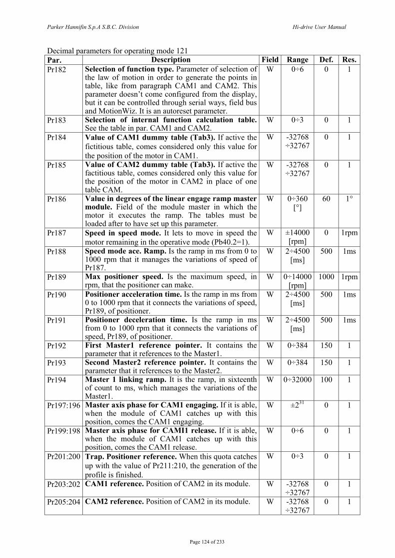
Parker Hannifin S.p.A S.B.C. Division Hi-drive User Manual
Page 124 of 233
Decimal parameters for operating mode 121 Par. Description Field Range Def. Res.Pr182 Selection of function type. Parameter of selection of
the law of motion in order to generate the points in table, like from paragraph CAM1 and CAM2. This parameter doesn’t come configured from the display, but it can be controlled through serial ways, field bus and MotionWiz. It is an autoreset parameter.
W 0÷6 0 1
Pr183 Selection of internal function calculation table. See the table in par. CAM1 and CAM2.
W 0÷3 0 1
Pr184 Value of CAM1 dummy table (Tab3). If active the fictitious table, comes considered only this value for the position of the motor in CAM1.
W -32768 ÷32767
0 1
Pr185 Value of CAM2 dummy table (Tab3). If active the factitious table, comes considered only this value for the position of the motor in CAM2 in place of one table CAM.
W -32768 ÷32767
0 1
Pr186 Value in degrees of the linear engage ramp master module. Field of the module master in which the motor it executes the ramp. The tables must be loaded after to have set up this parameter.
W 0÷360 [°]
60 1°
Pr187 Speed in speed mode. It lets to move in speed the motor remaining in the operative mode (Pb40.2=1).
W ±14000 [rpm]
0 1rpm
Pr188 Speed mode ace. Ramp. Is the ramp in ms from 0 to 1000 rpm that it manages the variations of speed of Pr187.
W 2÷4500 [ms]
500 1ms
Pr189 Max positioner speed. Is the maximum speed, in rpm, that the positioner can make.
W 0÷14000 [rpm]
1000 1rpm
Pr190 Positioner acceleration time. Is the ramp in ms from 0 to 1000 rpm that it connects the variations of speed, Pr189, of positioner.
W 2÷4500 [ms]
500 1ms
Pr191 Positioner deceleration time. Is the ramp in ms from 0 to 1000 rpm that it connects the variations of speed, Pr189, of positioner.
W 2÷4500 [ms]
500 1ms
Pr192 First Master1 reference pointer. It contains the parameter that it references to the Master1.
W 0÷384 150 1
Pr193 Second Master2 reference pointer. It contains the parameter that it references to the Master2.
W 0÷384 150 1
Pr194 Master 1 linking ramp. It is the ramp, in sixteenth of count to ms, which manages the variations of the Master1.
W 0÷32000 100 1
Pr197:196 Master axis phase for CAM1 engaging. If it is able, when the module of CAM1 catches up with this position, comes the CAM1 engaging.
W ±231 0 1
Pr199:198 Master axis phase for CAMI1 release. If it is able, when the module of CAM1 catches up with this position, comes the CAM1 release.
W 0÷6 0 1
Pr201:200 Trap. Positioner reference. When this quota catches up with the value of Pr211:210, the generation of the profile is finished.
W 0÷3 0 1
Pr203:202 CAM1 reference. Position of CAM2 in its module. W -32768 ÷32767
0 1
Pr205:204 CAM2 reference. Position of CAM2 in its module. W -32768 ÷32767
0 1
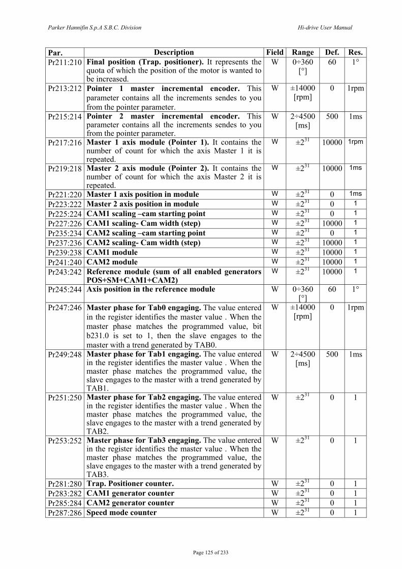
Parker Hannifin S.p.A S.B.C. Division Hi-drive User Manual
Page 125 of 233
Par. Description Field Range Def. Res.Pr211:210 Final position (Trap. positioner). It represents the
quota of which the position of the motor is wanted to be increased.
W 0÷360 [°]
60 1°
Pr213:212 Pointer 1 master incremental encoder. This parameter contains all the increments sendes to you from the pointer parameter.
W ±14000 [rpm]
0 1rpm
Pr215:214 Pointer 2 master incremental encoder. This parameter contains all the increments sendes to you from the pointer parameter.
W 2÷4500 [ms]
500 1ms
Pr217:216 Master 1 axis module (Pointer 1). It contains the number of count for which the axis Master 1 it is repeated.
W ±231 10000 1rpm
Pr219:218 Master 2 axis module (Pointer 2). It contains the number of count for which the axis Master 2 it is repeated.
W ±231 10000 1ms
Pr221:220 Master 1 axis position in module W ±231 0 1ms Pr223:222 Master 2 axis position in module W ±231 0 1 Pr225:224 CAM1 scaling –cam starting point W ±231 0 1 Pr227:226 CAM1 scaling- Cam width (step) W ±231 10000 1 Pr235:234 CAM2 scaling –cam starting point W ±231 0 1 Pr237:236 CAM2 scaling- Cam width (step) W ±231 10000 1 Pr239:238 CAM1 module W ±231 10000 1 Pr241:240 CAM2 module W ±231 10000 1 Pr243:242 Reference module (sum of all enabled generators
POS+SM+CAM1+CAM2) W ±231 10000 1
Pr245:244 Axis position in the reference module W 0÷360 [°]
60 1°
Pr247:246 Master phase for Tab0 engaging. The value entered in the register identifies the master value . When the master phase matches the programmed value, bit b231.0 is set to 1, then the slave engages to the master with a trend generated by TAB0.
W ±14000 [rpm]
0 1rpm
Pr249:248 Master phase for Tab1 engaging. The value entered in the register identifies the master value . When the master phase matches the programmed value, the slave engages to the master with a trend generated by TAB1.
W 2÷4500 [ms]
500 1ms
Pr251:250 Master phase for Tab2 engaging. The value entered in the register identifies the master value . When the master phase matches the programmed value, the slave engages to the master with a trend generated by TAB2.
W ±231 0 1
Pr253:252 Master phase for Tab3 engaging. The value entered in the register identifies the master value . When the master phase matches the programmed value, the slave engages to the master with a trend generated by TAB3.
W ±231 0 1
Pr281:280 Trap. Positioner counter. W ±231 0 1 Pr283:282 CAM1 generator counter W ±231 0 1 Pr285:284 CAM2 generator counter W ±231 0 1 Pr287:286 Speed mode counter W ±231 0 1
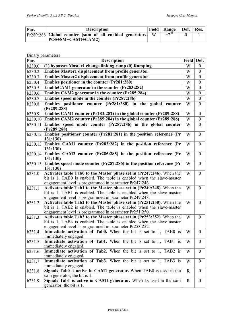
Parker Hannifin S.p.A S.B.C. Division Hi-drive User Manual
Page 126 of 233
Par. Description Field Range Def. Res.Pr289:288 Global counter (sum of all enabled generators
POS+SM+CAM1+CAM2) W ±231 0 1
Binary parameters Par. Description Field Def.b230.0 (1) bypasses Master1 change linking ramp (0) Ramping. W 0 b230.2 Enables Master1 displacement from profile generator W 0 b230.3 Enables Master2 displacement from profile generator W 0 b230.4 Enables positioner in the counter (Pr281:280) W 0 b230.5 EnableCAM1 generator in the counter (Pr283:282) W 0 b230.6 Enables CAM2 generator in the counter (Pr285:284) W 0 b230.7 Enables speed mode in the counter (Pr287:286) W 0 b230.8 Enables positioner counter (Pr281:280) in the global counter
(Pr289:288) W 0
b230.9 Enables CAM1 counter (Pr283:282) in the global counter (Pr289:288) W 0 b230.10 Enables CAM2 counter (Pr285:284) in the global counter (Pr289:288) W 0 b230.11 Enables speed mode counter (Pr287:286) in the global counter
(Pr289:288) W 0
b230.12 Enables positioner counter (Pr281:281) in the position reference (Pr 131:130)
W 0
b230.13 Enables CAM1 counter (Pr283:282) in the position reference (Pr 131:130)
W 0
b230.14 Enables CAM2 counter (Pr285:285) in the position reference (Pr 131:130)
W 0
b230.15 Enables speed mode counter (Pr287:286) in the position reference (Pr 131:130)
W 0
b231.0 Activates table Tab0 to the Master phase set in (Pr247:246). When the bit is 1, TAB0 is enabled. The table is enabled when the slave-master engagement level is programmed in parameter Pr247:246.
W 0
b231.1 Activates table Tab1 to the Master phase set in (Pr249:248). When the bit is 1, TAB1 is enabled. The table is enabled when the slave-master engagement level is programmed in parameter Pr249:248.
W 0
b231.2 Activates table Tab2 to the Master phase set in (Pr251:250). When the bit is 1, TAB2 is enabled. The table is enabled when the slave-master engagement level is programmed in parameter Pr251:250.
W 0
b231.3 Activates table Tab3 to the Master phase set in (Pr253:252). When the bit is 1, TAB3 is enabled. The table is enabled when the slave-master engagement level is programmed in parameter Pr253:252.
W 0
b231.4 Immediate activation of Tab0. When the bit is set to 1, TAB0 is immediately engaged.
W 0
b231.5 Immediate activation of Tab1. When the bit is set to 1, TAB1 is immediately engaged.
W 0
b231.6 Immediate activation of Tab2. When the bit is set to 1, TAB2 is immediately engaged.
W 0
b231.7 Immediate activation of Tab3. When the bit is set to 1, TAB3 is immediately engaged.
W 0
b231.8 Signals Tab0 is active in CAM1 generator. When TAB0 is used in the cam generator, the bit is 1.
R 0
b231.9 Signals Tab1 is active in CAM1 generator. When 1s used in the cam generator, the bit is 1.
R 0
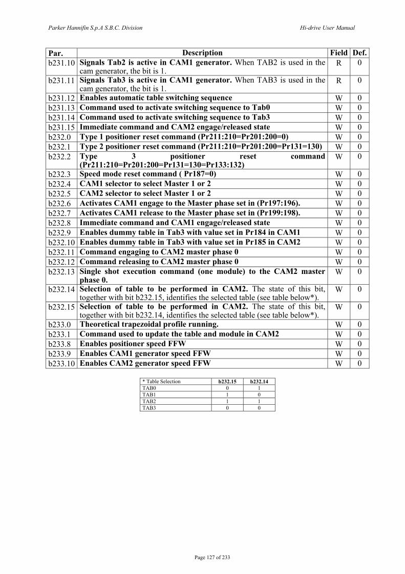
Parker Hannifin S.p.A S.B.C. Division Hi-drive User Manual
Page 127 of 233
Par. Description Field Def.b231.10 Signals Tab2 is active in CAM1 generator. When TAB2 is used in the
cam generator, the bit is 1. R 0
b231.11 Signals Tab3 is active in CAM1 generator. When TAB3 is used in the cam generator, the bit is 1.
R 0
b231.12 Enables automatic table switching sequence W 0 b231.13 Command used to activate switching sequence to Tab0 W 0 b231.14 Command used to activate switching sequence to Tab3 W 0 b231.15 Immediate command and CAM2 engage/released state W 0 b232.0 Type 1 positioner reset command (Pr211:210=Pr201:200=0) W 0 b232.1 Type 2 positioner reset command (Pr211:210=Pr201:200=Pr131=130) W 0 b232.2 Type 3 positioner reset command
(Pr211:210=Pr201:200=Pr131=130=Pr133:132) W 0
b232.3 Speed mode reset command ( Pr187=0) W 0 b232.4 CAM1 selector to select Master 1 or 2 W 0 b232.5 CAM2 selector to select Master 1 or 2 W 0 b232.6 Activates CAM1 engage to the Master phase set in (Pr197:196). W 0 b232.7 Activates CAM1 release to the Master phase set in (Pr199:198). W 0 b232.8 Immediate command and CAM1 engage/released state W 0 b232.9 Enables dummy table in Tab3 with value set in Pr184 in CAM1 W 0 b232.10 Enables dummy table in Tab3 with value set in Pr185 in CAM2 W 0 b232.11 Command engaging to CAM2 master phase 0 W 0 b232.12 Command releasing to CAM2 master phase 0 W 0 b232.13 Single shot execution command (one module) to the CAM2 master
phase 0. W 0
b232.14 Selection of table to be performed in CAM2. The state of this bit, together with bit b232.15, identifies the selected table (see table below*).
W 0
b232.15 Selection of table to be performed in CAM2. The state of this bit, together with bit b232.14, identifies the selected table (see table below*).
W 0
b233.0 Theoretical trapezoidal profile running. W 0 b233.1 Command used to update the table and module in CAM2 W 0 b233.8 Enables positioner speed FFW W 0 b233.9 Enables CAM1 generator speed FFW W 0 b233.10 Enables CAM2 generator speed FFW W 0
* Table Selection b232.15 b232.14 TAB0 0 1 TAB1 1 0 TAB2 1 1 TAB3 0 0
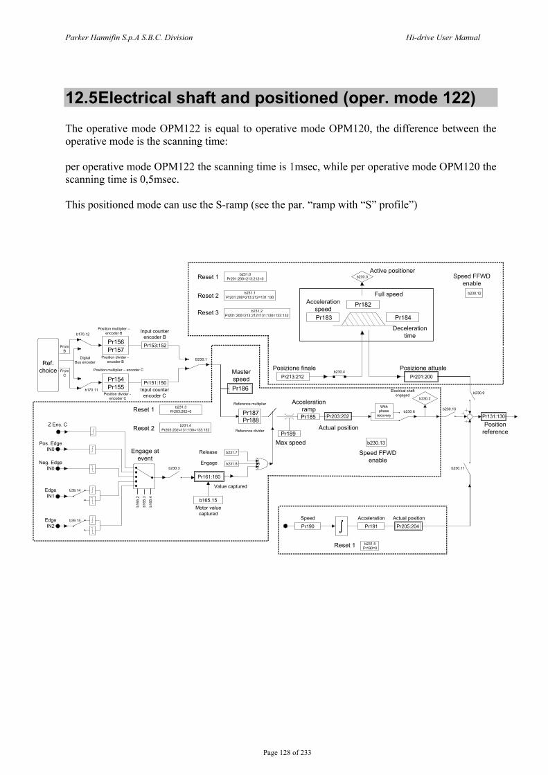
Parker Hannifin S.p.A S.B.C. Division Hi-drive User Manual
Page 128 of 233
12.5 Electrical shaft and positioned (oper. mode 122) The operative mode OPM122 is equal to operative mode OPM120, the difference between the operative mode is the scanning time: per operative mode OPM122 the scanning time is 1msec, while per operative mode OPM120 the scanning time is 0,5msec. This positioned mode can use the S-ramp (see the par. “ramp with “S” profile”)
Ref. choice
Pr156Pr157
Pr154Pr155
Pr153:152
Pr186
Pr187Pr188
b170.12
Engage at event
Z Enc. C
Pr151:150b170.11
B230.1
b39.14
b39.15
b230.3
Pr161:160
b165.15
b231.8
b231.7
Pr189
Pr185 Pr203:202
b230.13
b230.10
b230.11
b230.9b230.2
b230.6
Pr190 Pr191 Pr205:204
Pr131:130
With phase
recovery
Pr201:200Pr213:212
Pr183 Pr184
Pr182
b230.0
b230.4
Speed Acceleration Actual position
Position reference
Posizione attuale
Speed FFWDenable
Actual position
Accelerationramp
Posizione finale
Deceleration time
Acceleration speed
Full speed
Active positioner
b230.12
Electrical shaft engaged
Max speed
Speed FFWD enable
Reference multiplier
Reference divider
Release
Engage
Value captured
Motor value captured
Input counter encoder B
Position multiplier – encoder C
Position divider - encoder B
Master speed
Pos. Edge IN0
Neg. Edge IN0
Edge IN1
Edge IN2
DigitalBus encoder
FromB
FromC
b231.0Pr201:200=213:212=0
b231.1Pr201:200=213:212=131:130
b231.2Pr201:200=213:212=131:130=133:132
Reset 1
Reset 2
Reset 3
b231.3Pr203:202=0
b231.4Pr203:202=131:130=133:132
Reset 1
Reset 2
b231.5Pr190=0Reset 1
b165
.2
b165
.3
b165
.4
Position divider - encoder C
Position multiplier –encoder B
Input counter encoder C
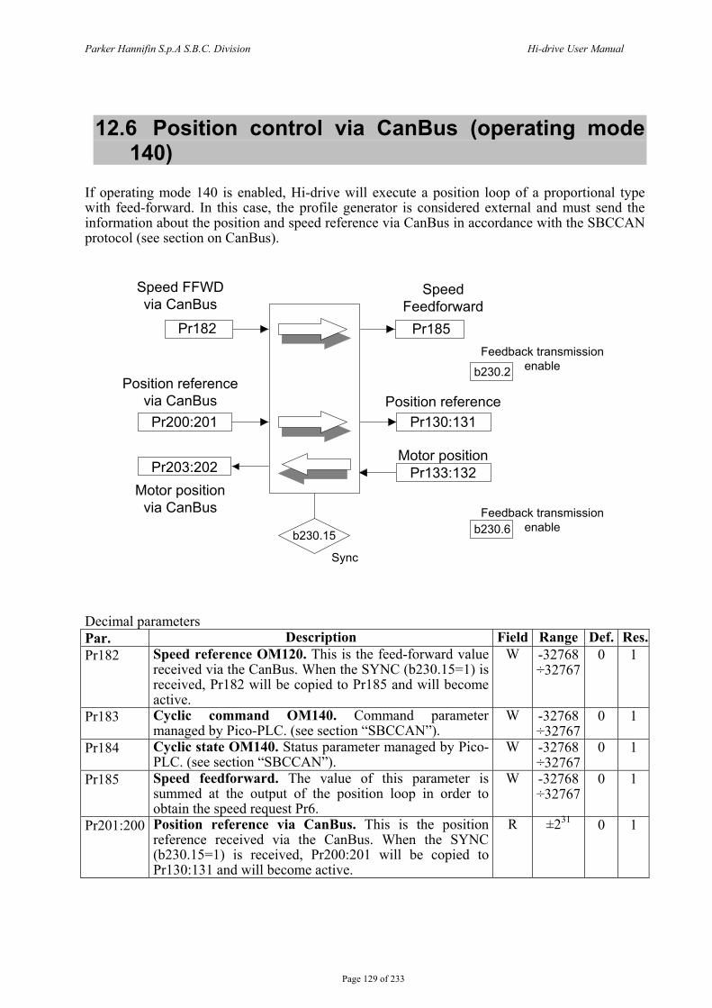
Parker Hannifin S.p.A S.B.C. Division Hi-drive User Manual
Page 129 of 233
12.6 Position control via CanBus (operating mode 140)
If operating mode 140 is enabled, Hi-drive will execute a position loop of a proportional type with feed-forward. In this case, the profile generator is considered external and must send the information about the position and speed reference via CanBus in accordance with the SBCCAN protocol (see section on CanBus).
Pr182 Pr185
Pr200:201
Pr203:202
Pr130:131
Pr133:132
b230.2
b230.6b230.15
Speed FFWDvia CanBus
Position referencevia CanBus
Motor positionvia CanBus
SpeedFeedforward
Position reference
Motor position
Feedback transmission enable
Feedback transmissionenable
Sync Decimal parameters Par. Description Field Range Def. Res.Pr182 Speed reference OM120. This is the feed-forward value
received via the CanBus. When the SYNC (b230.15=1) is received, Pr182 will be copied to Pr185 and will become active.
W -32768 ÷32767
0 1
Pr183 Cyclic command OM140. Command parameter managed by Pico-PLC. (see section “SBCCAN”).
W -32768 ÷32767
0 1
Pr184 Cyclic state OM140. Status parameter managed by Pico-PLC. (see section “SBCCAN”).
W -32768 ÷32767
0 1
Pr185 Speed feedforward. The value of this parameter is summed at the output of the position loop in order to obtain the speed request Pr6.
W -32768 ÷32767
0 1
Pr201:200 Position reference via CanBus. This is the position reference received via the CanBus. When the SYNC (b230.15=1) is received, Pr200:201 will be copied to Pr130:131 and will become active.
R ±231 0 1
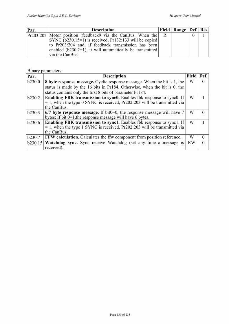
Parker Hannifin S.p.A S.B.C. Division Hi-drive User Manual
Page 130 of 233
Par. Description Field Range Def. Res.Pr203:202 Motor position (feedback9 via the CanBus. When the
SYNC (b230.15=1) is received, Pr132:133 will be copied to Pr203:204 and, if feedback transmission has been enabled (b230.2=1), it will automatically be transmitted via the CanBus.
R 0 1
Binary parameters Par. Description Field Def.b230.0 8 byte response message. Cyclic response message. When the bit is 1, the
status is made by the 16 bits in Pr184. Otherwise, when the bit is 0, the status contains only the first 8 bits of parameter Pr184.
W 0
b230.2 Enabling FBK transmission to sync0. Enables fbk response to sync0. If = 1, when the type 0 SYNC is received, Pr202:203 will be transmitted via the CanBus.
W 1
b230.3 6/7 byte response message. If bit0=0, the response message will have 7 bytes; If bit 0=1,the response message will have 6 bytes.
W 0
b230.6 Enabling FBK transmission to sync1. Enables fbk response to sync1. If = 1, when the type 1 SYNC is received, Pr202:203 will be transmitted via the CanBus.
W 1
b230.7 FFW calculation. Calculates the ffw component from position reference. W 0 b230.15 Watchdog sync. Sync receive Watchdog (set any time a message is
received). RW 0
Parker Hannifin S.p.A S.B.C. Division Hi-drive User Manual
Page 131 of 233
12.7 Additional useful functions
12.7.1 Capturing values Three event-capturing functions are available to capture either the position fbk or either encoder inputs (B or C). These functions can be programmed both in terms of the value to be captured, that can be alternatively: - POSITION LOOP FBK, - ENCODER B, - ENCODER C, and in terms of the event when the value must be captured, that can be alternatively:
- zero encoder point dog (encoder in connector) - rising edge of digital input IN0 - falling edge of digital input IN0 - digital input IN1 edge (programmable rise/fall through b39.14) - digital input IN2 edge (programmable rise/fall through b39.15)
When a synchronous motor with speed feedback from an incremental encoder is used, any time the unit is powered up a phasing procedure will have to be carried out. The phasing process may end (if Pr65.3=1) with a “fine” phasing on the input encoder zero point dog. In this case, the encoder will need to be mechanically phased when it is installed on the motor. As sincos encoders can be used encoders with a number of sines per revolution corresponding to 2 elevated to the nth power. Through the position FBK the motor position can be identified and saved in specific registers. The drive allows to chose where to capture the value, in which of three registers to save it and what type of event shall prompt the capture of the value. Parameters Pr164, Pr165 and Pr166 are used to manage events, registers and captured values:
- bits 0 and 1 define which FBK shall be used to capture the value. The setting of these bits therefore determines the data input;
- bits 2, 3 and 4 define the selection of the event that prompts the value capture: that is, these bits identify the event that shall determine the timing of the value capture;
- bit 15 controls the value capture. This means that, any time this bit is 1, a value has been captured. This bit, however, is not self-resetting and its status must be changed (through Pico-PLC or serial command) in order to be able to see when the next values are sensed.
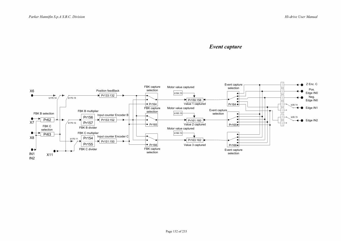
Parker Hannifin S.p.A S.B.C. Division Hi-drive User Manual
Page 132 of 233
Pr133:132
Pr153:152
Pr151:150
Pr156Pr157
Pr154
Pr155
Pr63
Pr62
FBK B selection
FBK C selection
X6
X7
X8
IN1IN2
X11
Position feedBack
FBK B multiplier
FBK C multiplier
FBK B divider
FBK C divider
Input counter Encoder B
Input counter Encoder C
Motor value captured
b166.15
b165.15
b164.15
Pr159:158
Pr161:160
Pr163:162
FBK captureselection
Pr164
Pr165
Pr166
Pr164
Pr165
Pr166
Event captureselection
Value 1 captured
Z Enc. C
Pos. Edge IN0
Neg. Edge IN0
Edge IN1
Edge IN2
b39.14
b39.15
b170.14 b170.15
b170.12
b170.11
FBK captureselection
FBK captureselection
Motor value captured
Motor value capturedValue 2 captured
Value 3 captured
Event captureselection
Event captureselection
Event capture
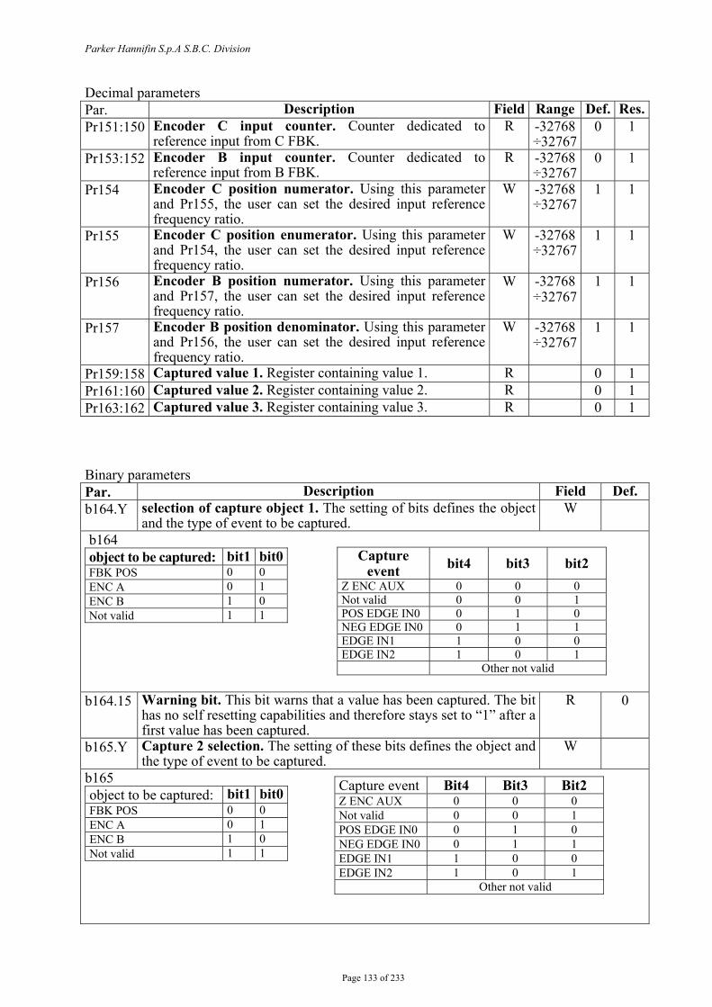
Parker Hannifin S.p.A S.B.C. Division
Page 133 of 233
Decimal parameters Par. Description Field Range Def. Res.Pr151:150 Encoder C input counter. Counter dedicated to
reference input from C FBK. R -32768
÷32767 0 1
Pr153:152 Encoder B input counter. Counter dedicated to reference input from B FBK.
R -32768 ÷32767
0 1
Pr154 Encoder C position numerator. Using this parameter and Pr155, the user can set the desired input reference frequency ratio.
W -32768 ÷32767
1 1
Pr155 Encoder C position enumerator. Using this parameter and Pr154, the user can set the desired input reference frequency ratio.
W -32768 ÷32767
1 1
Pr156 Encoder B position numerator. Using this parameter and Pr157, the user can set the desired input reference frequency ratio.
W -32768 ÷32767
1 1
Pr157 Encoder B position denominator. Using this parameter and Pr156, the user can set the desired input reference frequency ratio.
W -32768 ÷32767
1 1
Pr159:158 Captured value 1. Register containing value 1. R 0 1 Pr161:160 Captured value 2. Register containing value 2. R 0 1 Pr163:162 Captured value 3. Register containing value 3. R 0 1 Binary parameters Par. Description Field Def. b164.Y selection of capture object 1. The setting of bits defines the object
and the type of event to be captured. W
b164 object to be captured: bit1 bit0 FBK POS 0 0 ENC A 0 1 ENC B 1 0 Not valid 1 1
b164.15 Warning bit. This bit warns that a value has been captured. The bit
has no self resetting capabilities and therefore stays set to “1” after a first value has been captured.
R 0
b165.Y Capture 2 selection. The setting of these bits defines the object and the type of event to be captured.
W
b165 object to be captured: bit1 bit0 FBK POS 0 0 ENC A 0 1 ENC B 1 0 Not valid 1 1
Capture event Bit4 Bit3 Bit2 Z ENC AUX 0 0 0 Not valid 0 0 1 POS EDGE IN0 0 1 0 NEG EDGE IN0 0 1 1 EDGE IN1 1 0 0 EDGE IN2 1 0 1 Other not valid
Capture event bit4 bit3 bit2
Z ENC AUX 0 0 0 Not valid 0 0 1 POS EDGE IN0 0 1 0 NEG EDGE IN0 0 1 1 EDGE IN1 1 0 0 EDGE IN2 1 0 1
Other not valid
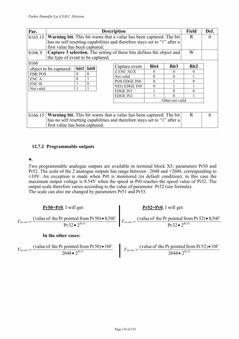
Parker Hannifin S.p.A S.B.C. Division
Page 134 of 233
Par. Description Field Def. b165.15 Warning bit. This bit warns that a value has been captured. The bit
has no self resetting capabilities and therefore stays set to “1” after a first value has been captured.
R 0
b166.Y Capture 3 selection. The setting of these bits defines the object and the type of event to be captured.
W
b166 object to be captured: bit1 bit0 FBK POS 0 0 ENC A 0 1 ENC B 1 0 Not valid 1 1
b166.15 Warning bit. This bit warns that a value has been captured. The bit
has no self resetting capabilities and therefore stays set to “1” after a first value has been captured.
R 0
12.7.2 Programmable outputs Two programmable analogue outputs are available in terminal block X5: parameters Pr50 and Pr52. The scale of the 2 analogue outputs has range between –2048 and +2048, corresponding to ±10V. An exception is made when Pr0 is monitored (in default condition); in this case the maximum output voltage is 8.54V when the speed in Pr0 reaches the speed value of Pr32. The output scale therefore varies according to the value of parameter Pr32 (see formula). The scale can also me changed by parameters Pr51 and Pr53.
Pr50=Pr0, I will get: Pr52=Pr0, I will get:
51Pr.232Pr
54,8)50Pr from pointedPr theof value(•
•=
VV outan 53Pr.232Pr
54,8)52Pr from pointedPr theof value(•
•=
VV outan
In the other cases:
51Pr.22048
10)50Pr from pointedPr theof value(•
•=
VV outan 53Pr.22048
10)52Pr from pointedPr theof value(•
•=
VV outan
Capture event Bit4 Bit3 Bit2 Z ENC AUX 0 0 0 Not valid 0 0 1 POS EDGE IN0 0 1 0 NEG EDGE IN0 0 1 1 EDGE IN1 1 0 0 EDGE IN2 1 0 1 Other not valid
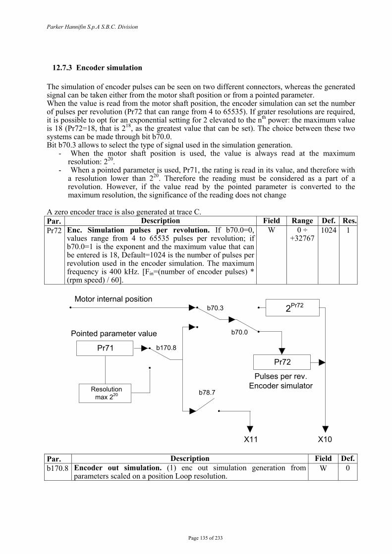
Parker Hannifin S.p.A S.B.C. Division
Page 135 of 233
12.7.3 Encoder simulation The simulation of encoder pulses can be seen on two different connectors, whereas the generated signal can be taken either from the motor shaft position or from a pointed parameter. When the value is read from the motor shaft position, the encoder simulation can set the number of pulses per revolution (Pr72 that can range from 4 to 65535). If grater resolutions are required, it is possible to opt for an exponential setting for 2 elevated to the nth power: the maximum value is 18 (Pr72=18, that is 218, as the greatest value that can be set). The choice between these two systems can be made through bit b70.0. Bit b70.3 allows to select the type of signal used in the simulation generation.
- When the motor shaft position is used, the value is always read at the maximum resolution: 220.
- When a pointed parameter is used, Pr71, the rating is read in its value, and therefore with a resolution lower than 220. Therefore the reading must be considered as a part of a revolution. However, if the value read by the pointed parameter is converted to the maximum resolution, the significance of the reading does not change
A zero encoder trace is also generated at trace C. Par. Description Field Range Def. Res.Pr72 Enc. Simulation pulses per revolution. If b70.0=0,
values range from 4 to 65535 pulses per revolution; if b70.0=1 is the exponent and the maximum value that can be entered is 18, Default=1024 is the number of pulses per revolution used in the encoder simulation. The maximum frequency is 400 kHz. [Fin=(number of encoder pulses) * (rpm speed) / 60].
W 0 ÷ +32767
1024 1
Motor internal position
Pointed parameter value
Pr71
Pr72
2Pr72b70.3
b170.8
b78.7
b70.0
X11 X10
Resolution max 220
Pulses per rev. Encoder simulator
Par. Description Field Def.b170.8 Encoder out simulation. (1) enc out simulation generation from
parameters scaled on a position Loop resolution. W 0
Parker Hannifin S.p.A S.B.C. Division
Page 136 of 233
12.7.4 Motor cogging compensation At lower speed levels, motor rotation can be “disturbed” by a cogging effect. The drive can mitigate this effect. Before activating this function, go through the following steps:
- initial conditions: o no alarm is active, Pr23=0; o parameter Pr181=0; o enable the drive; o the motor rotation speed is ≤ 2rpm
- motor cogging mapping calculation: o issue command b42.7=1
At this stage the drive automatically creates a table containing useful data to compensate motor cogging.
The calculating function ends when bit b42.7 returns to“0”. At this point the motor can be stopped. In order to enable motor cogging compensation,, set bit b39.10=1. N.B. The table that the drive has generated during the calculation of cogging mapping is not
deleted when default parameters are loaded. In order to modify these data, repeat the mapping calculation.
12.7.5 Multiturn absolute encoder phasing on “zero” machine With a multiturn absolute encoder, initialize the absolute position read at power up on the motor position by following the procedure below: - position the mechanical axis on the desired machine point - disable drive hardware b41.5=0 - set desired position in Pr69:68 - enter command b64.9 to perform the write procedure in the absolute encoder. - After having entered a multiturn phasing command b64.9, bit b41.6, indicating “phasing ok”
is set to zero. Switch the electronics off and on again to be able to perform other axis enabling procedures.
Par.
Description Field Def.b170.13 Multiturn position read. (1) if multiturn absolute position is read at
power up R 0
The range of absolute position depends of the encoder and it’s equal to:
2 2 169Pr turnsofnumber
•±

Parker Hannifin S.p.A S.B.C. Division
Page 137 of 233
()
12.7.6 Encoder CAN If this function is enable, it is possible to generate and receive the “encoder like” signals by the CAN line (there are two different CAN lines: CAN A and CAN B, which is qualified to communicate with others Hi-drive only), which replaces quadratures signal. The running is trasparent, respect to the traditional encoder signals: the CAN line must be connected instead of quadratures signals, and must be considered that every encoder signal is available every 1,024msec over the CAN (every 1,024msec per CAN A, every 5msec per CAN B), and the signal has 4byte for data. It is possible to have up to a maximum of three encoder signals, if the speed of the CAN is 1Mbs, and only one encoder signal if the speed is 500kbs. Hi-drive needs some bit and parameters about the correct operation:
Par. Description Field Range Def. Ris.Pr260 Encoder CAN A OUT baudrate. W 0÷31 1 1 Pr261 Address of CAN A OUT. W 0÷31 1 1 Pr326 Pointer of encoder CAN A OUT. W 0÷255 - 1 Pr327 Address of CAN A IN. W 0÷255 - 1 Pr328 Divisor factor of encoder IN. Reduction ratio
denominator of the input encoder counting by CAN A.
W 0÷255 1 1
Pr329 Multiplicative factor of encoder IN. Reduction ratio numerator of the input encoder counting by CAN A.
W 0÷255 1 1
Pr331:330 Counting encoder CAN A IN. R ±231 - 1
Par. Description Field Def.b70.7 Encoder CAN A IN function enabled. It activates at the
successive switching on after save the setting of the bit. W 0
b70.8 Encoder CAN A OUT function enabled. It activates at the successive switching on after save the setting of the bit.
W 0
b70.10 Encoder CAN OUT virtual enabled. Enable the encoder CAN virtual through the parameter pointed from Pr326 or through the motor position.
W 0
b79.5 Initialization of CAN A OUT line. W 0 The encoder CAN A IN is active in input and accepts the CAN signal with address setting into Pr327. The output encoder CAN generates a encoder signal with the same address to CAN node (Pr261). Nel caso in cui l’indirizzo dell’encoder in ingresso (Pr327) venisse impostato pari al valore dell’indirizzo in uscita (Pr261) l’asse che genera l’encoder CAN leggerà come ingresso il segnale encoder CAN in uscita. If the address of the input encoder (Pr327) is setting at the same value of the output address (Pr261), the axe which generates the encoder CAN, reads input the encoder CAN output signal. If the command b70.10 is enable, is possible to generate a encoder virtual signal, setting b70.10=1, by the parameter pointed from Pr326.
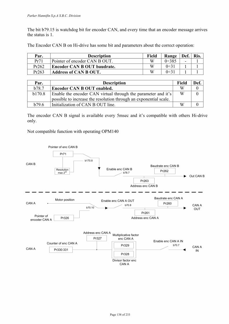
Parker Hannifin S.p.A S.B.C. Division
Page 138 of 233
The bit b79.15 is watchdog bit for encoder CAN, and every time that an encoder message arrives the status is 1. The Encoder CAN B on Hi-drive has some bit and parameters about the correct operation:
Par. Description Field Range Def. Ris.Pr71 Pointer of encoder CAN B OUT. W 0÷385 - 1 Pr262 Encoder CAN B OUT baudrate. W 0÷31 1 1 Pr263 Address of CAN B OUT. W 0÷31 1 1
Par. Description Field Def.b78.7 Encoder CAN B OUT enabled. W 0 b170.8 Enable the encoder CAN virtual through the parameter and it’s
possible to increase the resolution through an exponential scale. W 0
b79.6 Initialization of CAN B OUT line. W 0 The encoder CAN B signal is available every 5msec and it’s compatible with others Hi-drive only. Not compatible function with operating OPM140
b70.10b70.8
b70.7
Pr260
Address enc CAN APr261
Pr329
Pr328
Pr327
Pr326
Pr330:331
CAN ABaudrate enc CAN A
Multiplicative factor enc CAN A
Address enc CAN A
Counter of enc CAN A
Pointer of encoder CAN A
Motor position
CAN A
Divisor factor enc CAN A
Enable enc CAN A IN
Enable enc CAN A OUTCAN AOUT
CAN AIN
Pr71
b170.8
Resolution max 220 b78.7
Out CAN BPr263
Pr262Baudrate enc CAN B
Address enc CAN B
Enable enc CAN B
CAN B
Pointer of enc CAN B
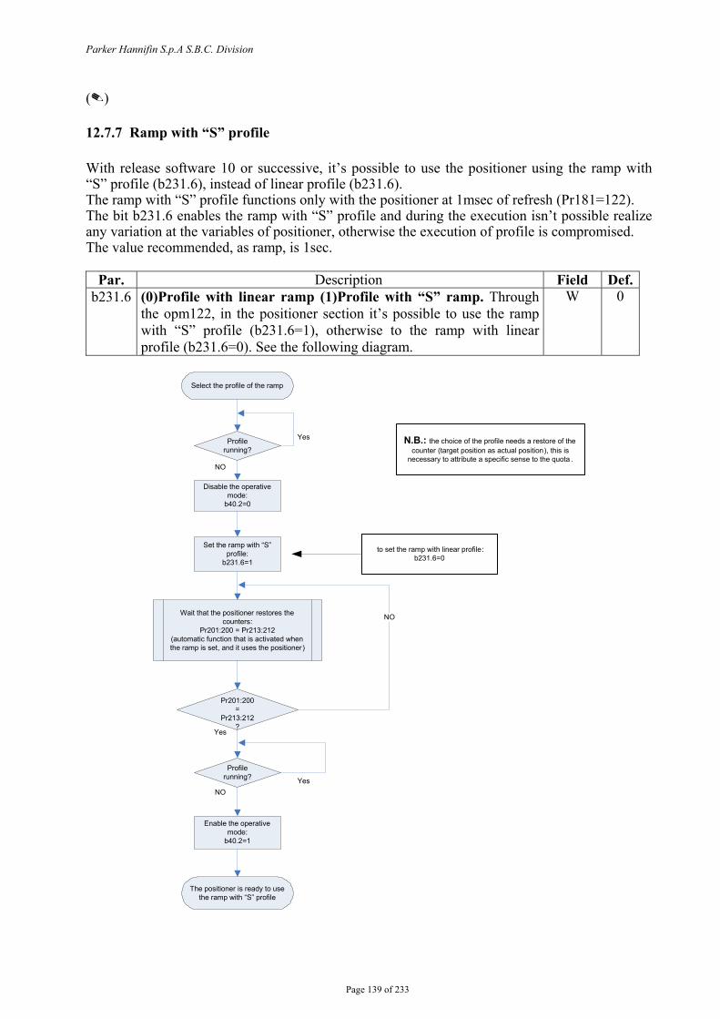
Parker Hannifin S.p.A S.B.C. Division
Page 139 of 233
()
12.7.7 Ramp with “S” profile With release software 10 or successive, it’s possible to use the positioner using the ramp with “S” profile (b231.6), instead of linear profile (b231.6). The ramp with “S” profile functions only with the positioner at 1msec of refresh (Pr181=122). The bit b231.6 enables the ramp with “S” profile and during the execution isn’t possible realize any variation at the variables of positioner, otherwise the execution of profile is compromised. The value recommended, as ramp, is 1sec.
Par. Description Field Def.b231.6 (0)Profile with linear ramp (1)Profile with “S” ramp. Through
the opm122, in the positioner section it’s possible to use the ramp with “S” profile (b231.6=1), otherwise to the ramp with linear profile (b231.6=0). See the following diagram.
W 0
Disable the operative mode:
b40.2=0
Profilerunning?
Select the profile of the ramp
Wait that the positioner restores the counters:
Pr201:200 = Pr213:212(automatic function that is activated when the ramp is set, and it uses the positioner)
Set the ramp with “S” profile:
b231.6=1
Pr201:200=
Pr213:212?
Profile running?
Enable the operative mode:
b40.2=1
NO
The positioner is ready to use the ramp with “S” profile
Yes
Yes
YesNO
NO
N.B.: the choice of the profile needs a restore of the counter (target position as actual position), this is
necessary to attribute a specific sense to the quota .
to set the ramp with linear profile: b231.6=0
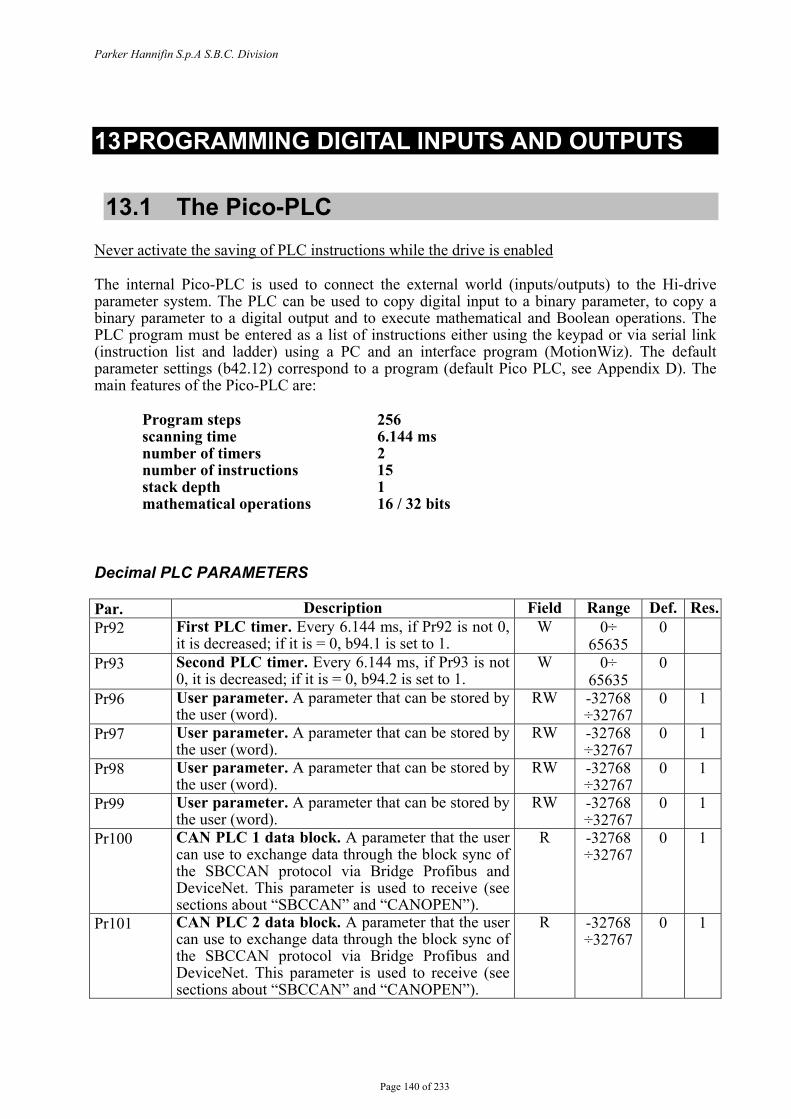
Parker Hannifin S.p.A S.B.C. Division
Page 140 of 233
13 PROGRAMMING DIGITAL INPUTS AND OUTPUTS
13.1 The Pico-PLC Never activate the saving of PLC instructions while the drive is enabled The internal Pico-PLC is used to connect the external world (inputs/outputs) to the Hi-drive parameter system. The PLC can be used to copy digital input to a binary parameter, to copy a binary parameter to a digital output and to execute mathematical and Boolean operations. The PLC program must be entered as a list of instructions either using the keypad or via serial link (instruction list and ladder) using a PC and an interface program (MotionWiz). The default parameter settings (b42.12) correspond to a program (default Pico PLC, see Appendix D). The main features of the Pico-PLC are:
Program steps 256 scanning time 6.144 ms number of timers 2 number of instructions 15 stack depth 1 mathematical operations 16 / 32 bits
Decimal PLC PARAMETERS Par. Description Field Range Def. Res.Pr92 First PLC timer. Every 6.144 ms, if Pr92 is not 0,
it is decreased; if it is = 0, b94.1 is set to 1. W 0÷
65635 0
Pr93 Second PLC timer. Every 6.144 ms, if Pr93 is not 0, it is decreased; if it is = 0, b94.2 is set to 1.
W 0÷ 65635
0
Pr96 User parameter. A parameter that can be stored by the user (word).
RW -32768 ÷32767
0 1
Pr97 User parameter. A parameter that can be stored by the user (word).
RW -32768 ÷32767
0 1
Pr98 User parameter. A parameter that can be stored by the user (word).
RW -32768 ÷32767
0 1
Pr99 User parameter. A parameter that can be stored by the user (word).
RW -32768 ÷32767
0 1
Pr100 CAN PLC 1 data block. A parameter that the user can use to exchange data through the block sync of the SBCCAN protocol via Bridge Profibus and DeviceNet. This parameter is used to receive (see sections about “SBCCAN” and “CANOPEN”).
R -32768 ÷32767
0 1
Pr101 CAN PLC 2 data block. A parameter that the user can use to exchange data through the block sync of the SBCCAN protocol via Bridge Profibus and DeviceNet. This parameter is used to receive (see sections about “SBCCAN” and “CANOPEN”).
R -32768 ÷32767
0 1

Parker Hannifin S.p.A S.B.C. Division
Page 141 of 233
Par. Description Field Range Def. Res.Pr102 CAN PLC 3 data block. A parameter that the user
can use to exchange data through the block sync of the SBCCAN protocol via Bridge Profibus and DeviceNet. This parameter is used to receive (see sections about “SBCCAN” and “CANOPEN”).
R -32768 ÷32767
0 1
Pr103 CAN PLC 4 data block. A parameter that the user can use to exchange data through the block sync of the SBCCAN protocol via Bridge Profibus and DeviceNet. This parameter is used to receive (see sections about “SBCCAN” and “CANOPEN”).
R -32768 ÷32767
0 1
Pr104 CAN PLC 5 data block. A parameter that the user can use to exchange data through the block sync of the SBCCAN protocol via Bridge Profibus and DeviceNet. This parameter is used to receive (see sections about “SBCCAN” and “CANOPEN”).
W -32768 ÷32767
0 1
Pr105 CAN PLC 6 data block. A parameter that the user can use to exchange data through the block sync of the SBCCAN protocol via Bridge Profibus and DeviceNet. This parameter is used to receive (see sections about “SBCCAN” and “CANOPEN”).
W -32768 ÷32767
0 1
Pr106 CAN PLC 7 data block. A parameter that the user can use to exchange data through the block sync of the SBCCAN protocol via Bridge Profibus and DeviceNet. This parameter is used to receive (see sections about “SBCCAN” and “CANOPEN”).
W -32768 ÷32767
0 1
Pr107 CAN PLC 8 data block. A parameter that the user can use to exchange data through the block sync of the SBCCAN protocol via Bridge Profibus and DeviceNet. This parameter is used to receive (see sections about “SBCCAN” and “CANOPEN”).
W -32768 ÷32767
0 1
Pr109:108 Spare data. Dedicated to CanOpen, this parameter contains the message with the data to be sent.
W -32768 ÷32767
0
Pr110 User parameter. A parameter that can be stored by the user (word).
RW -32768 ÷32767
0 1
Pr111 User parameter. A parameter that can be stored by the user (word).
RW -32768 ÷32767
0 1
Pr112 User parameter. A parameter that can be stored by the user (word).
RW -32768 ÷32767
0 1
Pr113 User parameter. A parameter that can be stored by the user (word).
RW -32768 ÷32767
0 1
Pr114 User parameter. A parameter that can be stored by the user (word).
RW -32768 ÷32767
0 1
Pr115 User parameter. A parameter that can be stored by the user (word).
RW -32768 ÷32767
0 1
Pr116 User parameter. A parameter that can be stored by the user (word).
RW -32768 ÷32767
0 1
Pr117 User parameter. A parameter that can be stored by the user (word).
RW -32768 ÷32767
0 1
Pr118 User parameter. A parameter that can be stored by the user (word).
RW -32768 ÷32767
0 1
Pr119 User parameter. A parameter that can be stored by the user (word).
RW -32768 ÷32767
0 1
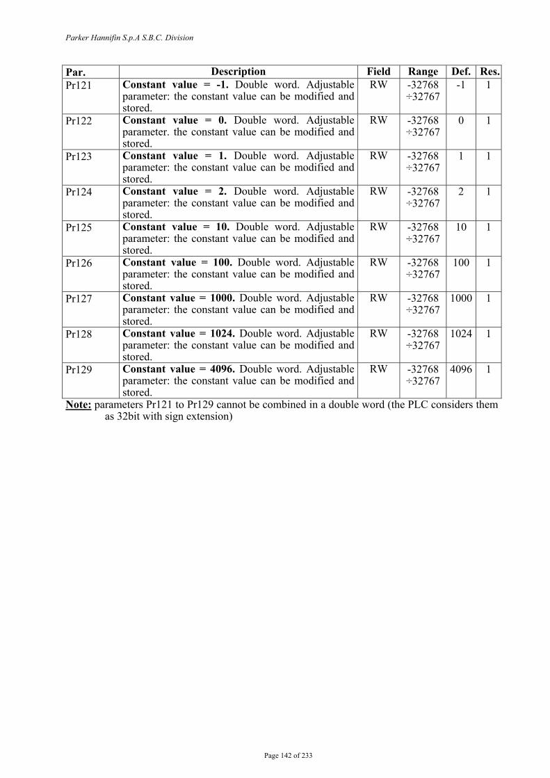
Parker Hannifin S.p.A S.B.C. Division
Page 142 of 233
Par. Description Field Range Def. Res.Pr121 Constant value = -1. Double word. Adjustable
parameter: the constant value can be modified and stored.
RW -32768 ÷32767
-1 1
Pr122 Constant value = 0. Double word. Adjustable parameter. the constant value can be modified and stored.
RW -32768 ÷32767
0 1
Pr123 Constant value = 1. Double word. Adjustable parameter: the constant value can be modified and stored.
RW -32768 ÷32767
1 1
Pr124 Constant value = 2. Double word. Adjustable parameter: the constant value can be modified and stored.
RW -32768 ÷32767
2 1
Pr125 Constant value = 10. Double word. Adjustable parameter: the constant value can be modified and stored.
RW -32768 ÷32767
10 1
Pr126 Constant value = 100. Double word. Adjustable parameter: the constant value can be modified and stored.
RW -32768 ÷32767
100 1
Pr127 Constant value = 1000. Double word. Adjustable parameter: the constant value can be modified and stored.
RW -32768 ÷32767
1000 1
Pr128 Constant value = 1024. Double word. Adjustable parameter: the constant value can be modified and stored.
RW -32768 ÷32767
1024 1
Pr129 Constant value = 4096. Double word. Adjustable parameter: the constant value can be modified and stored.
RW -32768 ÷32767
4096 1
Note: parameters Pr121 to Pr129 cannot be combined in a double word (the PLC considers them as 32bit with sign extension)
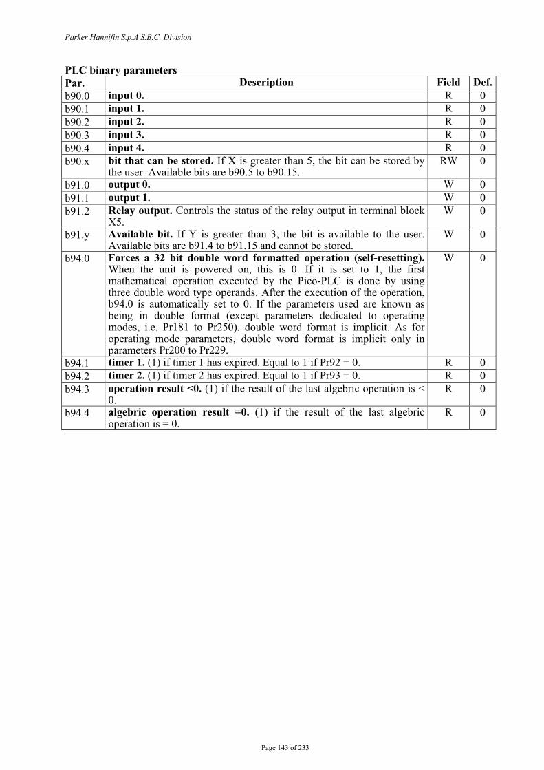
Parker Hannifin S.p.A S.B.C. Division
Page 143 of 233
PLC binary parameters Par. Description Field Def.b90.0 input 0. R 0 b90.1 input 1. R 0 b90.2 input 2. R 0 b90.3 input 3. R 0 b90.4 input 4. R 0 b90.x bit that can be stored. If X is greater than 5, the bit can be stored by
the user. Available bits are b90.5 to b90.15. RW 0
b91.0 output 0. W 0 b91.1 output 1. W 0 b91.2 Relay output. Controls the status of the relay output in terminal block
X5. W 0
b91.y Available bit. If Y is greater than 3, the bit is available to the user. Available bits are b91.4 to b91.15 and cannot be stored.
W 0
b94.0 Forces a 32 bit double word formatted operation (self-resetting). When the unit is powered on, this is 0. If it is set to 1, the first mathematical operation executed by the Pico-PLC is done by using three double word type operands. After the execution of the operation, b94.0 is automatically set to 0. If the parameters used are known as being in double format (except parameters dedicated to operating modes, i.e. Pr181 to Pr250), double word format is implicit. As for operating mode parameters, double word format is implicit only in parameters Pr200 to Pr229.
W 0
b94.1 timer 1. (1) if timer 1 has expired. Equal to 1 if Pr92 = 0. R 0 b94.2 timer 2. (1) if timer 2 has expired. Equal to 1 if Pr93 = 0. R 0 b94.3 operation result <0. (1) if the result of the last algebric operation is <
0. R 0
b94.4 algebric operation result =0. (1) if the result of the last algebric operation is = 0.
R 0
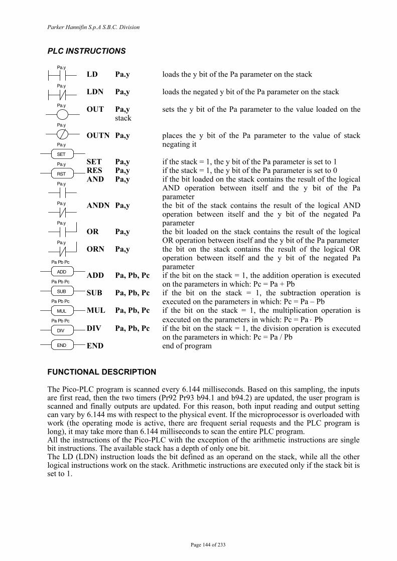
Parker Hannifin S.p.A S.B.C. Division
Page 144 of 233
PLC INSTRUCTIONS
FUNCTIONAL DESCRIPTION The Pico-PLC program is scanned every 6.144 milliseconds. Based on this sampling, the inputs are first read, then the two timers (Pr92 Pr93 b94.1 and b94.2) are updated, the user program is scanned and finally outputs are updated. For this reason, both input reading and output setting can vary by 6.144 ms with respect to the physical event. If the microprocessor is overloaded with work (the operating mode is active, there are frequent serial requests and the PLC program is long), it may take more than 6.144 milliseconds to scan the entire PLC program. All the instructions of the Pico-PLC with the exception of the arithmetic instructions are single bit instructions. The available stack has a depth of only one bit. The LD (LDN) instruction loads the bit defined as an operand on the stack, while all the other logical instructions work on the stack. Arithmetic instructions are executed only if the stack bit is set to 1.
LD Pa.y loads the y bit of the Pa parameter on the stack LDN Pa,y loads the negated y bit of the Pa parameter on the stack OUT Pa,y sets the y bit of the Pa parameter to the value loaded on the
stack OUTN Pa,y places the y bit of the Pa parameter to the value of stack
negating it SET Pa,y if the stack = 1, the y bit of the Pa parameter is set to 1 RES Pa,y if the stack = 1, the y bit of the Pa parameter is set to 0 AND Pa,y if the bit loaded on the stack contains the result of the logical
AND operation between itself and the y bit of the Pa parameter
ANDN Pa,y the bit of the stack contains the result of the logical AND operation between itself and the y bit of the negated Pa parameter
OR Pa,y the bit loaded on the stack contains the result of the logical OR operation between itself and the y bit of the Pa parameter
ORN Pa,y the bit on the stack contains the result of the logical OR operation between itself and the y bit of the negated Pa parameter
ADD Pa, Pb, Pc if the bit on the stack = 1, the addition operation is executed on the parameters in which: Pc = Pa + Pb
SUB Pa, Pb, Pc if the bit on the stack = 1, the subtraction operation is executed on the parameters in which: Pc = Pa – Pb
MUL Pa, Pb, Pc if the bit on the stack = 1, the multiplication operation is executed on the parameters in which: Pc = Pa ⋅ Pb
DIV Pa, Pb, Pc if the bit on the stack = 1, the division operation is executed on the parameters in which: Pc = Pa / Pb
END end of program
Pa.y
Pa.y
ADD Pa Pb Pc
Pa.y
Pa.y
SET Pa.y
END
Pa.y
Pa.y
SUB Pa Pb Pc
RST Pa.y
Pa.y
Pa.y
MUL Pa Pb Pc
DIV Pa Pb Pc

Parker Hannifin S.p.A S.B.C. Division
Page 145 of 233
For user convenience, truth tables of logical operations are given below.
The respective denied ANDN and ORN operations follow the same logic, except that the denied value of the specified bit will be used. 12 bits from b90.4 to b90.15 are reserved on the PLC and can be stored. 14 additional bits from b91.2 to b91.15 are available on the PLC but cannot be stored. They are always set to 0 when the converter is powered on. There are 14 word type user parameters, namely Pr95 to Pr99 and Pr110 to Pr119. They can be stored and used as double word parameters. Parameters Pr100 to PrP107 are dedicated to data exchange through the block sync of the SBC CAN protocol (used to exchange data via Profibus Device Net bridges). The Pico-PLC includes 9 constants for arithmetic operations, that is Pr121 to Pr129. When the default parameters are loaded, the constants have the values shown in the table and can be modified and stored with different values. These parameters are already programmed to be considered as a double word. When arithmetic instructions (ADD, SUB, MUL, DIV) are used, consider that the operators are assumed to be words and are signed. If a double word operation is required, set b94.0 = 1 before executing the operation. After the operation, the PLC will automatically set this bit to 0. Double parameters are treated as double words, so that in an operation such as [ADD 121,122,212] the result –1 will be written in the double word Pr212:213 without having to set b94.0=1 before the operation. If Pr100=-1 and Pr101=0 the operation [ADD 100,122,212] will give as a result Pr212:213=-1, while the same operation executed with b94.0=1 will assume Pr101 as the high word of the double word Pr100:101 and the result will be Pr212:213=65535. If the parameters used are known as being in double word format (except parameters dedicated to operating modes, i.e. Pr 181 to Pr 250), double word format is implicit. As for operating mode parameters, double word format is implicit only in parameters Pr200 to Pr229. Example: ADD 100 122 212 in double word. Pr100=-1; Pr101=0, in double word becomes Pr101:100, where Pr101 is the high word and Pr100 is the low word (H=0:L=-1), that is = 65535. Pr122=0; this is a 0 value constant considered in double word format (it will not be combined with Pr123 to form a double word parameter). The addition result is entered in Pr213:212=65535 (H=0:L=-1), where Pr213 takes the significance of the high word in the double word (H), whereas Pr212 takes the value of the low word (L). Note that in mathematical operations with double words, only the low word is shown (L), whereas the high word (H), which is the most significant, will appear in the following word.
At the end of each arithmetic operation, b94.3 is set to 0 in case of positive result and to 1 in case of negative result; similarly, b94.4 is set to 1 when the result is zero and to 0 if the result is not zero. These settings remain effective until the next arithmetic operation is executed (the operation is executed only if the stack bit is one). If the DIV operation is executed on a double word, the most significant part of the result contains the remainder of the division, that is, if b94.0=1 and the operation [DIV 129,127,100] is executed, the result will be Pr100=4 and Pr101=96.
AND logical operation bit A bit B result
0 0 0 0 1 0 1 0 0 1 1 1
OR logical operation bit A bit B result
0 0 0 0 1 1 1 0 1 1 1 1
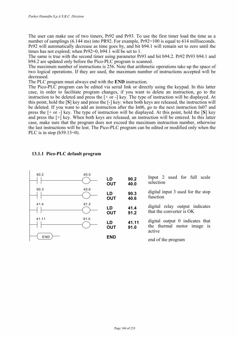
Parker Hannifin S.p.A S.B.C. Division
Page 146 of 233
The user can make use of two timers, Pr92 and Pr93. To use the first timer load the time as a number of samplings (6.144 ms) into PR92. For example, Pr92=100 is equal to 614 milliseconds. Pr92 will automatically decrease as time goes by, and bit b94.1 will remain set to zero until the times has not expired; when Pr92=0, b94.1 will be set to 1. The same is true with the second timer using parameter Pr93 and bit b94.2. Pr92 Pr93 b94.1 and b94.2 are updated only before the Pico-PLC program is scanned. The maximum number of instructions is 256. Note that arithmetic operations take up the space of two logical operations. If they are used, the maximum number of instructions accepted will be decreased. The PLC program must always end with the END instruction. The Pico-PLC program can be edited via serial link or directly using the keypad. In this latter case, in order to facilitate program changes, if you want to delete an instruction, go to the instruction to be deleted and press the [+ or -] key. The type of instruction will be displayed. At this point, hold the [S] key and press the [-] key: when both keys are released, the instruction will be deleted. If you want to add an instruction after the In06, go to the next instruction In07 and press the [+ or -] key. The type of instruction will be displayed. At this point, hold the [S] key and press the [+] key. When both keys are released, an instruction will be entered. In this latter case, make sure that the program does not exceed the maximum instruction number, otherwise the last instructions will be lost. The Pico-PLC program can be edited or modified only when the PLC is in stop (b39.13=0).
13.1.1 Pico-PLC default program
90.2
40.6
END
40.0
90.3
91.2 41.4
91.0 41.11
LD 90.2OUT 40.0 LD 90.3 OUT 40.6 LD 41.4 OUT 91.2 LD 41.11 OUT 91.0 END
Input 2 used for full scale selection digital input 3 used for the stop function digital relay output indicates that the converter is OK digital output 0 indicates that the thermal motor image is active end of the program
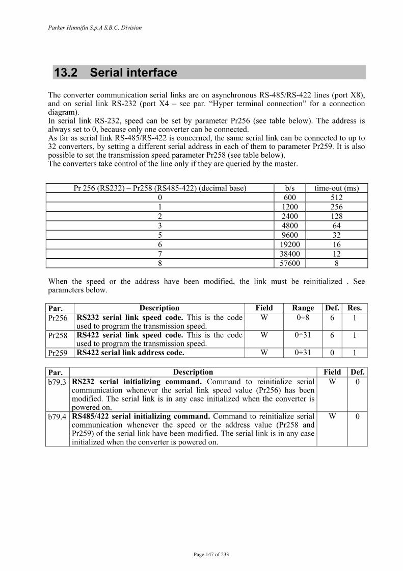
Parker Hannifin S.p.A S.B.C. Division
Page 147 of 233
13.2 Serial interface The converter communication serial links are on asynchronous RS-485/RS-422 lines (port X8), and on serial link RS-232 (port X4 – see par. “Hyper terminal connection” for a connection diagram). In serial link RS-232, speed can be set by parameter Pr256 (see table below). The address is always set to 0, because only one converter can be connected. As far as serial link RS-485/RS-422 is concerned, the same serial link can be connected to up to 32 converters, by setting a different serial address in each of them to parameter Pr259. It is also possible to set the transmission speed parameter Pr258 (see table below). The converters take control of the line only if they are queried by the master.
When the speed or the address have been modified, the link must be reinitialized . See parameters below. Par. Description Field Range Def. Res. Pr256 RS232 serial link speed code. This is the code
used to program the transmission speed. W 0÷8 6 1
Pr258 RS422 serial link speed code. This is the code used to program the transmission speed.
W 0÷31 6 1
Pr259 RS422 serial link address code. W 0÷31 0 1 Par. Description Field Def.b79.3 RS232 serial initializing command. Command to reinitialize serial
communication whenever the serial link speed value (Pr256) has been modified. The serial link is in any case initialized when the converter is powered on.
W 0
b79.4 RS485/422 serial initializing command. Command to reinitialize serial communication whenever the speed or the address value (Pr258 and Pr259) of the serial link have been modified. The serial link is in any case initialized when the converter is powered on.
W 0
Pr 256 (RS232) – Pr258 (RS485-422) (decimal base) b/s time-out (ms) 0 600 512 1 1200 256 2 2400 128 3 4800 64 5 9600 32 6 19200 16 7 38400 12 8 57600 8
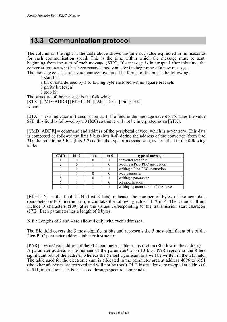
Parker Hannifin S.p.A S.B.C. Division
Page 148 of 233
13.3 Communication protocol The column on the right in the table above shows the time-out value expressed in milliseconds for each communication speed. This is the time within which the message must be sent, beginning from the start of each message (STX). If a message is interrupted after this time, the converter ignores what has been received and waits for the beginning of a new message. The message consists of several consecutive bits. The format of the bits is the following: 1 start bit 8 bit of data defined by a following byte enclosed within square brackets 1 parity bit (even) 1 stop bit The structure of the message is the following: [STX] [CMD+ADDR] [BK+LUN] [PAR] [D0]... [Dn] [CHK] where: [STX] = $7E indicator of transmission start. If a field in the message except STX takes the value $7E, this field is followed by a 0 ($00) so that it will not be interpreted as an [STX]. [CMD+ADDR] = command and address of the peripheral device, which is never zero. This data is composed as follows: the first 5 bits (bits 0-4) define the address of the converter (from 0 to 31); the remaining 3 bits (bits 5-7) define the type of message sent, as described in the following table:
[BK+LUN] = the field LUN (first 3 bits) indicates the number of bytes of the sent data (parameter or PLC instruction); it can take the following values: 1, 2 or 4. The value shall not include 0 characters ($00) after the values corresponding to the transmission start character ($7E). Each parameter has a length of 2 bytes. N.B.: Lengths of 2 and 4 are allowed only with even addresses . The BK field covers the 5 most significant bits and represents the 5 most significant bits of the Pico-PLC parameter address, table or instruction. [PAR] = write/read address of the PLC parameter, table or instruction (8bit low in the address) A parameter address is the number of the parameter* 2 on 13 bits: PAR represents the 8 less significant bits of the address, whereas the 5 most significant bits will be written in the BK field. The table used for the electronic cam is allocated in the parameter area at address 4096 to 6151 (the other addresses are reserved and will not be used). PLC instructions are mapped at address 0 to 511, instructions can be accessed through specific commands.
CMD bit 7 bit 6 bit 5 type of message 1 0 0 1 converter response 2 0 1 0 reading a Pico-PLC instruction 3 0 1 1 writing a Pico-PLC instruction 4 1 0 0 read parameter 5 1 0 1 writing a parameter 6 1 1 0 bit modification 7 1 1 1 writing a parameter to all the slaves
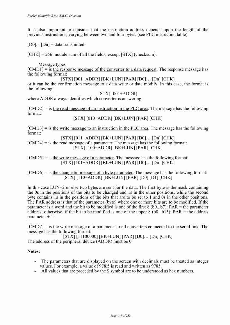
Parker Hannifin S.p.A S.B.C. Division
Page 149 of 233
It is also important to consider that the instruction address depends upon the length of the previous instructions, varying between two and four bytes, (see PLC instruction table). [D0]... [Dn] = data transmitted. [CHK] = 256 module sum of all the fields, except [STX] (checksum).
Message types [CMD1] = is the response message of the converter to a data request. The response message has the following format:
[STX] [001+ADDR] [BK+LUN] [PAR] [D0]… [Dn] [CHK] or it can be the confirmation message to a data write or data modify. In this case, the format is the following:
[STX] [001+ADDR] where ADDR always identifies which converter is answering. [CMD2] = is the read message of an instruction in the PLC area. The message has the following format:
[STX] [010+ADDR] [BK+LUN] [PAR] [CHK] [CMD3] = is the write message to an instruction in the PLC area. The message has the following format:
[STX] [011+ADDR] [BK+LUN] [PAR] [D0]… [Dn] [CHK] [CMD4] = is the read message of a parameter. The message has the following format:
[STX] [100+ADDR] [BK+LUN] [PAR] [CHK] [CMD5] = is the write message of a parameter. The message has the following format:
[STX] [101+ADDR] [BK+LUN] [PAR] [D0]… [Dn] [CHK]
[CMD6] = is the change bit message of a byte parameter. The message has the following format: [STX] [110+ADDR] [BK+LUN] [PAR] [D0] [D1] [CHK]
In this case LUN=2 or else two bytes are sent for the data. The first byte is the mask containing the 0s in the positions of the bits to be changed and 1s in the other positions, while the second byte contains 1s in the positions of the bits that are to be set to 1 and 0s in the other positions. The PAR address is that of the parameter (byte) where one or more bits are to be modified. If the parameter is a word and the bit to be modified is one of the first 8 (b0...b7): PAR = the parameter address; otherwise, if the bit to be modified is one of the upper 8 (b8...b15): PAR = the address parameter + 1. [CMD7] = is the write message of a parameter to all converters connected to the serial link. The message has the following format:
[STX] [11100000] [BK+LUN] [PAR] [D0]… [Dn] [CHK] The address of the peripheral device (ADDR) must be 0. Notes:
- The parameters that are displayed on the screen with decimals must be treated as integer values. For example, a value of 978.5 is read and written as 9785.
- All values that are preceded by the $ symbol are to be understood as hex numbers.
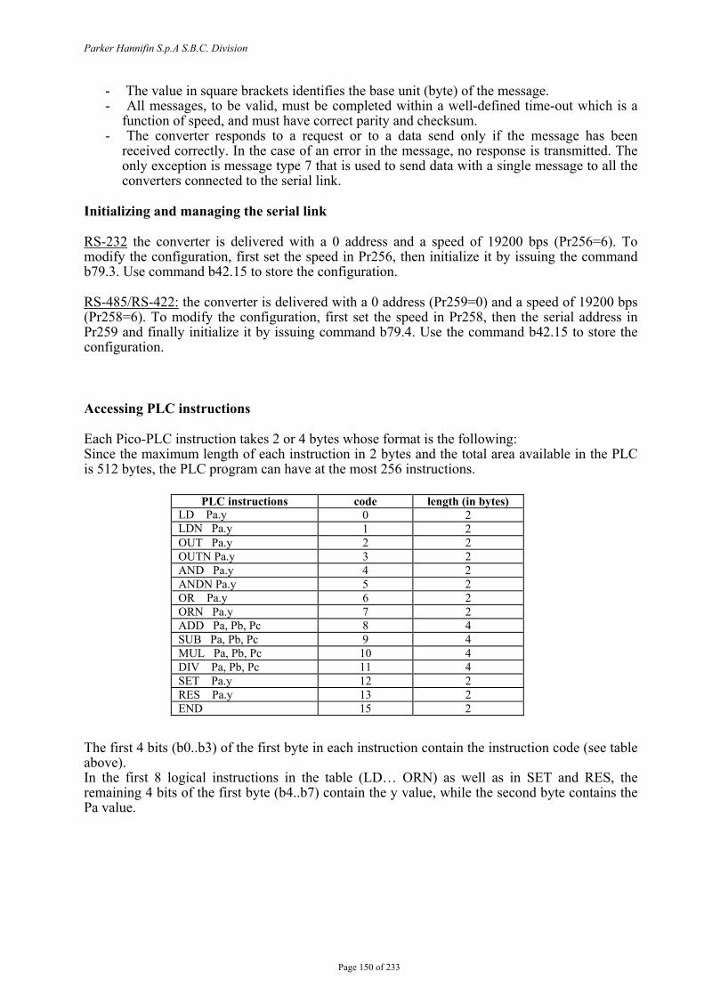
Parker Hannifin S.p.A S.B.C. Division
Page 150 of 233
- The value in square brackets identifies the base unit (byte) of the message. - All messages, to be valid, must be completed within a well-defined time-out which is a
function of speed, and must have correct parity and checksum. - The converter responds to a request or to a data send only if the message has been
received correctly. In the case of an error in the message, no response is transmitted. The only exception is message type 7 that is used to send data with a single message to all the converters connected to the serial link.
Initializing and managing the serial link RS-232 the converter is delivered with a 0 address and a speed of 19200 bps (Pr256=6). To modify the configuration, first set the speed in Pr256, then initialize it by issuing the command b79.3. Use command b42.15 to store the configuration. RS-485/RS-422: the converter is delivered with a 0 address (Pr259=0) and a speed of 19200 bps (Pr258=6). To modify the configuration, first set the speed in Pr258, then the serial address in Pr259 and finally initialize it by issuing command b79.4. Use the command b42.15 to store the configuration. Accessing PLC instructions
Each Pico-PLC instruction takes 2 or 4 bytes whose format is the following: Since the maximum length of each instruction in 2 bytes and the total area available in the PLC is 512 bytes, the PLC program can have at the most 256 instructions.
The first 4 bits (b0..b3) of the first byte in each instruction contain the instruction code (see table above). In the first 8 logical instructions in the table (LD… ORN) as well as in SET and RES, the remaining 4 bits of the first byte (b4..b7) contain the y value, while the second byte contains the Pa value.
PLC instructions code length (in bytes) LD Pa.y 0 2 LDN Pa.y 1 2 OUT Pa.y 2 2 OUTN Pa.y 3 2 AND Pa.y 4 2 ANDN Pa.y 5 2 OR Pa.y 6 2 ORN Pa.y 7 2 ADD Pa, Pb, Pc 8 4 SUB Pa, Pb, Pc 9 4 MUL Pa, Pb, Pc 10 4 DIV Pa, Pb, Pc 11 4 SET Pa.y 12 2 RES Pa.y 13 2 END 15 2
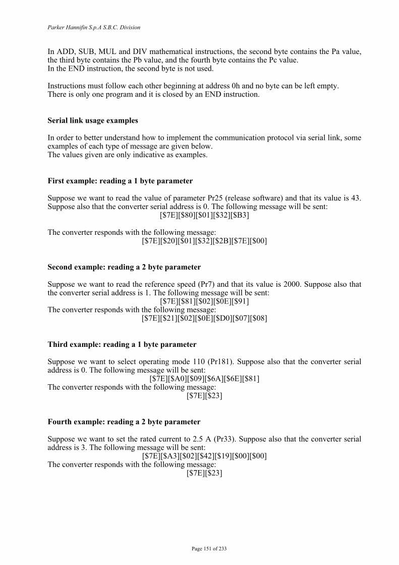
Parker Hannifin S.p.A S.B.C. Division
Page 151 of 233
In ADD, SUB, MUL and DIV mathematical instructions, the second byte contains the Pa value, the third byte contains the Pb value, and the fourth byte contains the Pc value. In the END instruction, the second byte is not used. Instructions must follow each other beginning at address 0h and no byte can be left empty. There is only one program and it is closed by an END instruction. Serial link usage examples In order to better understand how to implement the communication protocol via serial link, some examples of each type of message are given below. The values given are only indicative as examples. First example: reading a 1 byte parameter Suppose we want to read the value of parameter Pr25 (release software) and that its value is 43. Suppose also that the converter serial address is 0. The following message will be sent:
[$7E][$80][$01][$32][$B3]
The converter responds with the following message: [$7E][$20][$01][$32][$2B][$7E][$00]
Second example: reading a 2 byte parameter Suppose we want to read the reference speed (Pr7) and that its value is 2000. Suppose also that the converter serial address is 1. The following message will be sent:
[$7E][$81][$02][$0E][$91] The converter responds with the following message:
[$7E][$21][$02][$0E][$D0][$07][$08] Third example: reading a 1 byte parameter Suppose we want to select operating mode 110 (Pr181). Suppose also that the converter serial address is 0. The following message will be sent:
[$7E][$A0][$09][$6A][$6E][$81] The converter responds with the following message:
[$7E][$23] Fourth example: reading a 2 byte parameter Suppose we want to set the rated current to 2.5 A (Pr33). Suppose also that the converter serial address is 3. The following message will be sent:
[$7E][$A3][$02][$42][$19][$00][$00] The converter responds with the following message:
[$7E][$23]
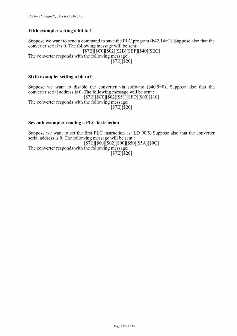
Parker Hannifin S.p.A S.B.C. Division
Page 152 of 233
Fifth example: setting a bit to 1 Suppose we want to send a command to save the PLC program (b42.14=1). Suppose also that the converter serial is 0. The following message will be sent:
[$7E][$C0][$02][$2B][$BF][$40][$EC] The converter responds with the following message:
[$7E][$20] Sixth example: setting a bit to 0 Suppose we want to disable the converter via software (b40.9=0). Suppose also that the converter serial address is 0. The following message will be sent :
[$7E][$C0][$02][$51][$FD][$00][$10] The converter responds with the following message:
[$7E][$20] Seventh example: reading a PLC instruction Suppose we want to set the first PLC instruction as: LD 90.5. Suppose also that the converter serial address is 0. The following message will be sent :
[$7E][$60][$02][$00][$50][$5A][$0C] The converter responds with the following message:
[$7E][$20]
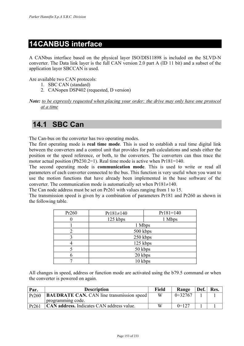
Parker Hannifin S.p.A S.B.C. Division
Page 153 of 233
14 CANBUS interface A CANbus interface based on the physical layer ISO/DIS11898 is included on the SLVD-N converter. The Data link layer is the full CAN version 2.0 part A (ID 11 bit) and a subset of the application layer SBCCAN is used. Are available two CAN protocols:
1. SBC CAN (standard) 2. CANopen DSP402 (requested, D version)
Note: to be expressly requested when placing your order: the drive may only have one protocol
at a time
14.1 SBC Can The Can-bus on the converter has two operating modes. The first operating mode is real time mode. This is used to establish a real time digital link between the converters and a control unit that provides for path calculations and sends either the position or the speed reference, or both, to the converters. The converters can thus trace the motor actual position (Pb230.2=1). Real time mode is active when Pr181=140. The second operating mode is communication mode. This is used to write or read all parameters of each converter connected to the bus. This function is very useful when you want to use the motion functions that have already been implemented in the base software of the converter. The communication mode is automatically set when Pr181≠140. The Can node address must be set on Pr261 with values ranging from 1 to 15. The transmission speed is given by a combination of parameters Pr181 and Pr260 as shown in the following table.
Pr260 Pr181≠140 Pr181=140 0 125 kbps 1 Mbps 1 1 Mbps 2 500 kbps 3 250 kbps 4 125 kbps 5 50 kbps 6 20 kbps 7 10 kbps
All changes in speed, address or function mode are activated using the b79.5 command or when the converter is powered on again. Par. Description Field Range Def. Res. Pr260 BAUDRATE CAN. CAN line transmission speed
programming code. W 0÷32767 1 1
Pr261 CAN address. Indicates CAN address value. W 0÷127 1 1
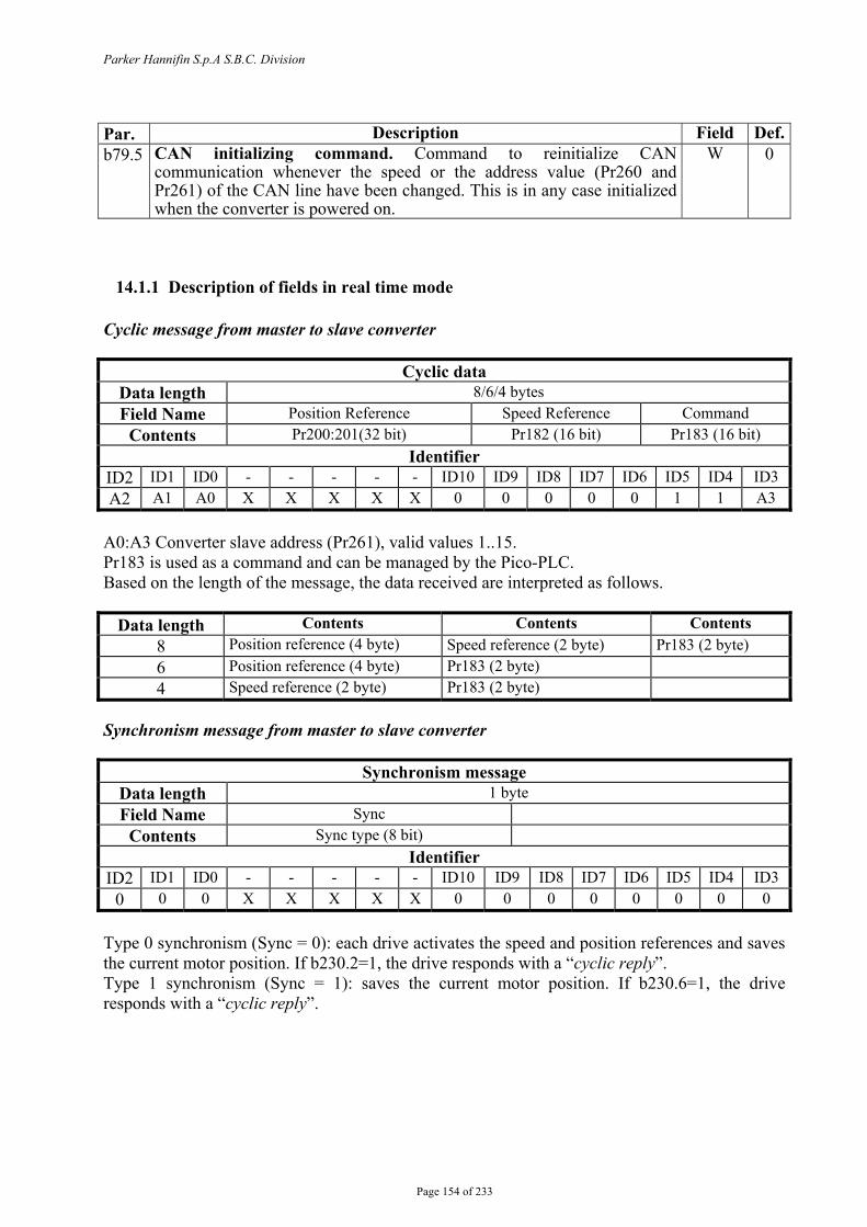
Parker Hannifin S.p.A S.B.C. Division
Page 154 of 233
Par. Description Field Def.b79.5 CAN initializing command. Command to reinitialize CAN
communication whenever the speed or the address value (Pr260 and Pr261) of the CAN line have been changed. This is in any case initialized when the converter is powered on.
W 0
14.1.1 Description of fields in real time mode Cyclic message from master to slave converter
Cyclic data Data length 8/6/4 bytes Field Name Position Reference Speed Reference Command
Contents Pr200:201(32 bit) Pr182 (16 bit) Pr183 (16 bit) Identifier
ID2 ID1 ID0 - - - - - ID10 ID9 ID8 ID7 ID6 ID5 ID4 ID3 A2 A1 A0 X X X X X 0 0 0 0 0 1 1 A3
A0:A3 Converter slave address (Pr261), valid values 1..15. Pr183 is used as a command and can be managed by the Pico-PLC. Based on the length of the message, the data received are interpreted as follows.
Data length Contents Contents Contents 8 Position reference (4 byte) Speed reference (2 byte) Pr183 (2 byte) 6 Position reference (4 byte) Pr183 (2 byte) 4 Speed reference (2 byte) Pr183 (2 byte)
Synchronism message from master to slave converter
Synchronism message Data length 1 byte Field Name Sync
Contents Sync type (8 bit) Identifier
ID2 ID1 ID0 - - - - - ID10 ID9 ID8 ID7 ID6 ID5 ID4 ID3 0 0 0 X X X X X 0 0 0 0 0 0 0 0
Type 0 synchronism (Sync = 0): each drive activates the speed and position references and saves the current motor position. If b230.2=1, the drive responds with a “cyclic reply”. Type 1 synchronism (Sync = 1): saves the current motor position. If b230.6=1, the drive responds with a “cyclic reply”.
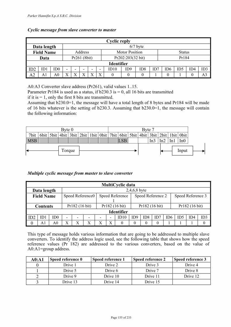
Parker Hannifin S.p.A S.B.C. Division
Page 155 of 233
Cyclic message from slave converter to master
Cyclic reply Data length 6/7 byte Field Name Address Motor Position Status
Data Pr261 (8bit) Pr202:203(32 bit) Pr184 Identifier
ID2 ID1 ID0 - - - - - ID10 ID9 ID8 ID7 ID6 ID5 ID4 ID3 A2 A1 A0 X X X X X 0 0 0 1 0 1 0 A3
A0:A3 Converter slave address (Pr261), valid values 1..15. Parameter Pr184 is used as a status, if b230.3 is = 0, all 16 bits are transmitted if it is = 1, only the first 8 bits are transmitted. Assuming that b230.0=1, the message will have a total length of 8 bytes and Pr184 will be made of 16 bits whatever is the setting of b230.3. Assuming that b230.0=1, the message will contain the following information:
Byte 0 Byte 7 7bit 6bit 5bit 4bit 3bit 2bit 1bit 0bit 7bit 6bit 5bit 4bit 3bit 2bit 1bit 0bit MSB LSB In3 In2 In1 In0 Multiple cyclic message from master to slave converter
MultiCyclic data Data length 2,4,6,8 byte Field Name Speed Reference0 Speed Reference
1 Speed Reference 2 Speed Reference 3
Contents Pr182 (16 bit) Pr182 (16 bit) Pr182 (16 bit) Pr182 (16 bit) Identifier
ID2 ID1 ID0 - - - - - ID10 ID9 ID8 ID7 ID6 ID5 ID4 ID3 0 A1 A0 X X X X X 0 0 0 0 1 1 1 0
This type of message holds various information that are going to be addressed to multiple slave converters. To identify the address logic used, see the following table that shows how the speed reference values (Pr 182) are addressed to the various converters, based on the value of A0:A1=group address.
A0:A1 Speed reference 0 Speed reference 1 Speed reference 2 Speed reference 3 0 Drive 1 Drive 2 Drive 3 Drive 4 1 Drive 5 Drive 6 Drive 7 Drive 8 2 Drive 9 Drive 10 Drive 11 Drive 12 3 Drive 13 Drive 14 Drive 15
Torque Input

Parker Hannifin S.p.A S.B.C. Division
Page 156 of 233
Multiple synchronism message from master to slave converter
MultiSynchronism message Data length 1,2,3,4 byte Field Name Command 0 Command 1 Command 2 Command 3
Contents Pr183 (8bit) Pr183 (8bit) Pr183 (8bit) Pr183 (8bit) Identifier
ID2 ID1 ID0 - - - - - ID10 ID9 ID8 ID7 ID6 ID5 ID4 ID3 0 0 0 X X X X X 0 0 0 0 0 1 0 0
Each drive activates the speed references and stores the current motor position. If b230.2=1, the drive responds with a “cyclic reply”. To this end, consider that, being a message directed to multiple converters, you need to be able to define which converters the “command” (first 8 bits of Pr183) is directed to. This information is reported in the following table:
Drive Command0 Command 1 Command 2 Command 3 Drive1 YES Drive2 YES Drive3 YES Drive4 YES Drive5 YES Drive6 YES Drive7 YES Drive8 YES Drive9 YES Drive10 YES Drive11 YES Drive12 YES Drive13 YES Drive14 YES Drive15 YES
Thus we can conclude that each command is composed of 8 bits and is shared by multiple converters. The user defines the bits within each command by programming the Pico-PLC of each converter.
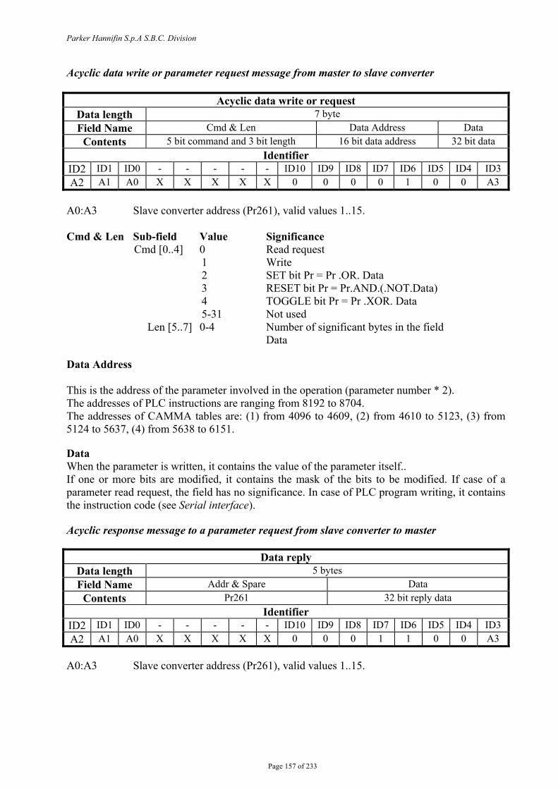
Parker Hannifin S.p.A S.B.C. Division
Page 157 of 233
Acyclic data write or parameter request message from master to slave converter
Acyclic data write or request Data length 7 byte Field Name Cmd & Len Data Address Data
Contents 5 bit command and 3 bit length 16 bit data address 32 bit data Identifier
ID2 ID1 ID0 - - - - - ID10 ID9 ID8 ID7 ID6 ID5 ID4 ID3 A2 A1 A0 X X X X X 0 0 0 0 1 0 0 A3
A0:A3 Slave converter address (Pr261), valid values 1..15. Cmd & Len Sub-field Value Significance
Cmd [0..4] 0 Read request 1 Write 2 SET bit Pr = Pr .OR. Data 3 RESET bit Pr = Pr.AND.(.NOT.Data) 4 TOGGLE bit Pr = Pr .XOR. Data 5-31 Not used
Len [5..7] 0-4 Number of significant bytes in the field Data
Data Address This is the address of the parameter involved in the operation (parameter number * 2). The addresses of PLC instructions are ranging from 8192 to 8704. The addresses of CAMMA tables are: (1) from 4096 to 4609, (2) from 4610 to 5123, (3) from 5124 to 5637, (4) from 5638 to 6151. Data When the parameter is written, it contains the value of the parameter itself.. If one or more bits are modified, it contains the mask of the bits to be modified. If case of a parameter read request, the field has no significance. In case of PLC program writing, it contains the instruction code (see Serial interface). Acyclic response message to a parameter request from slave converter to master
Data reply Data length 5 bytes Field Name Addr & Spare Data
Contents Pr261 32 bit reply data Identifier
ID2 ID1 ID0 - - - - - ID10 ID9 ID8 ID7 ID6 ID5 ID4 ID3 A2 A1 A0 X X X X X 0 0 0 1 1 0 0 A3
A0:A3 Slave converter address (Pr261), valid values 1..15.

Parker Hannifin S.p.A S.B.C. Division
Page 158 of 233
Broadcast write parameter message from master to slave converter
Broadcast data write Data length 7 bytes Field Name Cmd & Len Data Address Data
Contents 5 bit command and 3 bit length 16 bit data address 32 bit data Identifier
ID2 ID1 ID0 - - - - - ID10 ID9 ID8 ID7 ID6 ID5 ID4 ID3 1 1 1 X X X X X 0 0 1 0 0 0 1 1
Cmd & Len Sub-field Value Significance
Cmd [0..4] 0 Not used 1 Write 2 SET bit Pr = Pr .OR. Data 3 RESET bit Pr = Pr.AND.(.NOT.Data) 4 TOGGLE bit Pr = Pr .XOR. Data 5-31 Not used
Len [5..7] 0-4 Number of significant bytes in the field Data
Data Address This is the address of the parameter involved in the operation (parameter number * 2). The addresses of PLC instructions are in the range 8192 to 8704. The addresses of CAMMA tables are: (1) from 4096 to 4609, (2) from 4610 to 5123, (3) from 5124 to 5637, (4) from 5638 to 6151. Data When the parameter is written, it contains the value of the parameter itself.. If one or more bits are modified, it contains the mask of the bits to be modified. In case of PLC program writing, it contains the instruction code (see Serial interface).
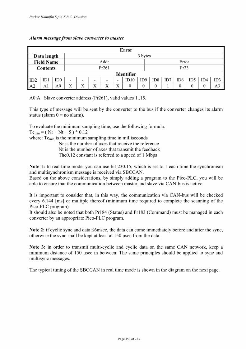
Parker Hannifin S.p.A S.B.C. Division
Page 159 of 233
Alarm message from slave converter to master
Error Data length 3 bytes Field Name Addr Error
Contents Pr261 Pr23 Identifier
ID2 ID1 ID0 - - - - - ID10 ID9 ID8 ID7 ID6 ID5 ID4 ID3 A2 A1 A0 X X X X X 0 0 0 1 0 0 0 A3 A0:A Slave converter address (Pr261), valid values 1..15. This type of message will be sent by the converter to the bus if the converter changes its alarm status (alarm 0 = no alarm). To evaluate the minimum sampling time, use the following formula: Tcmin = ( Nr + Nt + 5 ) * 0.12 where: Tcmin is the minimum sampling time in milliseconds Nr is the number of axes that receive the reference Nt is the number of axes that transmit the feedback The0.12 constant is referred to a speed of 1 Mbps Note 1: In real time mode, you can use bit 230.15, which is set to 1 each time the synchronism and multisynchronism message is received via SBCCAN. Based on the above considerations, by simply adding a program to the Pico-PLC, you will be able to ensure that the communication between master and slave via CAN-bus is active. It is important to consider that, in this way, the communication via CAN-bus will be checked every 6.144 [ms] or multiple thereof (minimum time required to complete the scanning of the Pico-PLC program). It should also be noted that both Pr184 (Status) and Pr183 (Command) must be managed in each converter by an appropriate Pico-PLC program. Note 2: if cyclic sync and data ≤6msec, the data can come immediately before and after the sync, otherwise the sync shall be kept at least at 150 μsec from the data. Note 3: in order to transmit multi-cyclic and cyclic data on the same CAN network, keep a minimum distance of 150 μsec in between. The same principles should be applied to sync and multisync messages. The typical timing of the SBCCAN in real time mode is shown in the diagram on the next page.

Parker Hannifin S.p.A S.B.C. Division Hi-drive User Manual
Page 160 of 233
Feedback from drive1 Feedback from drive3 Feedback from drive4 Feedback from drive2
cyclic msg to drive1 cyclic msg to drive 2 cyclic msg to drive 4 cyclic msg to drive 3
T X reference Sync
2 1
1
1
1
2
RX Feedback Change Pr of drive X Tx reference
TC
TX reference Sync
1 3
3
RX Feedback Require Pr of drive X Tx referenceDrive X reply
TC
SBCCAN
>400µs
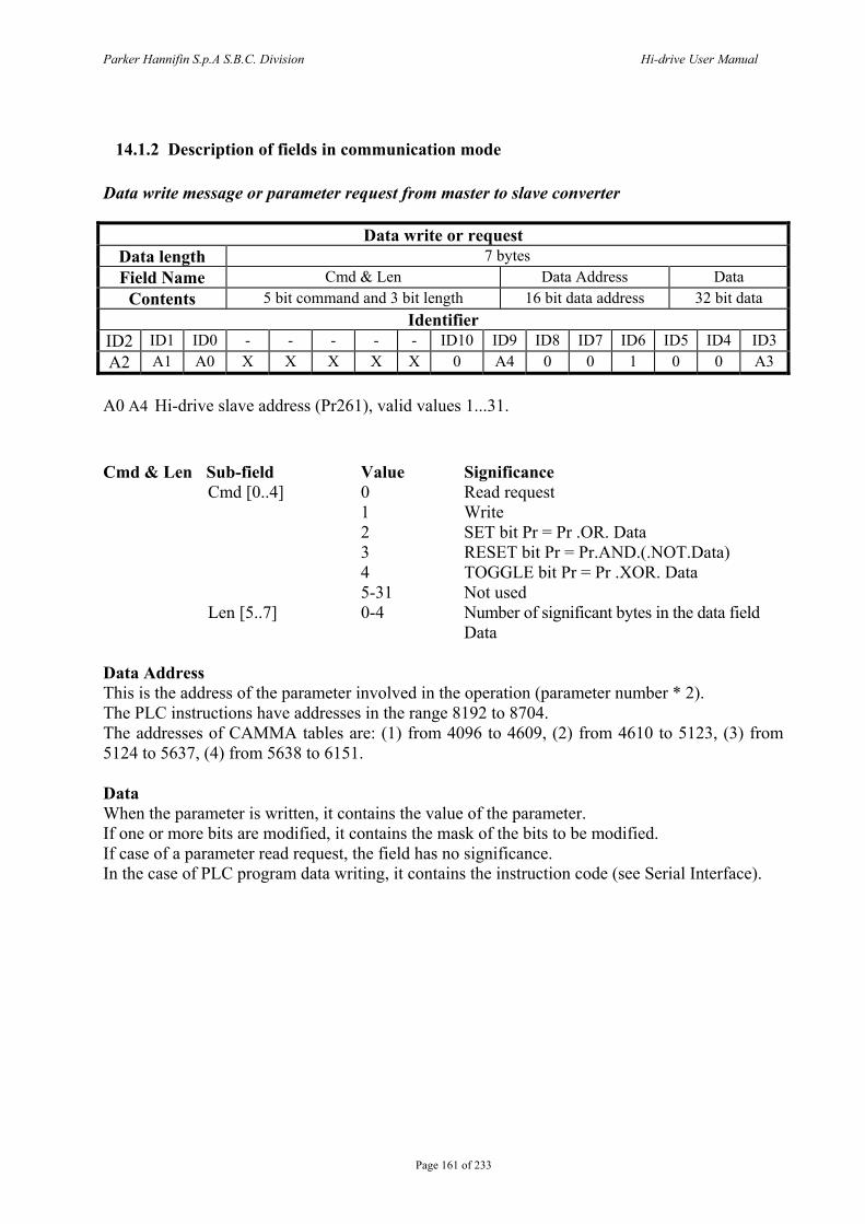
Parker Hannifin S.p.A S.B.C. Division Hi-drive User Manual
Page 161 of 233
14.1.2 Description of fields in communication mode Data write message or parameter request from master to slave converter
Data write or request Data length 7 bytes Field Name Cmd & Len Data Address Data
Contents 5 bit command and 3 bit length 16 bit data address 32 bit data Identifier
ID2 ID1 ID0 - - - - - ID10 ID9 ID8 ID7 ID6 ID5 ID4 ID3 A2 A1 A0 X X X X X 0 A4 0 0 1 0 0 A3
A0 A4 Hi-drive slave address (Pr261), valid values 1...31.
Cmd & Len Sub-field Value Significance
Cmd [0..4] 0 Read request 1 Write
2 SET bit Pr = Pr .OR. Data 3 RESET bit Pr = Pr.AND.(.NOT.Data) 4 TOGGLE bit Pr = Pr .XOR. Data
5-31 Not used Len [5..7] 0-4 Number of significant bytes in the data field
Data Data Address This is the address of the parameter involved in the operation (parameter number * 2). The PLC instructions have addresses in the range 8192 to 8704. The addresses of CAMMA tables are: (1) from 4096 to 4609, (2) from 4610 to 5123, (3) from 5124 to 5637, (4) from 5638 to 6151. Data When the parameter is written, it contains the value of the parameter. If one or more bits are modified, it contains the mask of the bits to be modified. If case of a parameter read request, the field has no significance. In the case of PLC program data writing, it contains the instruction code (see Serial Interface).
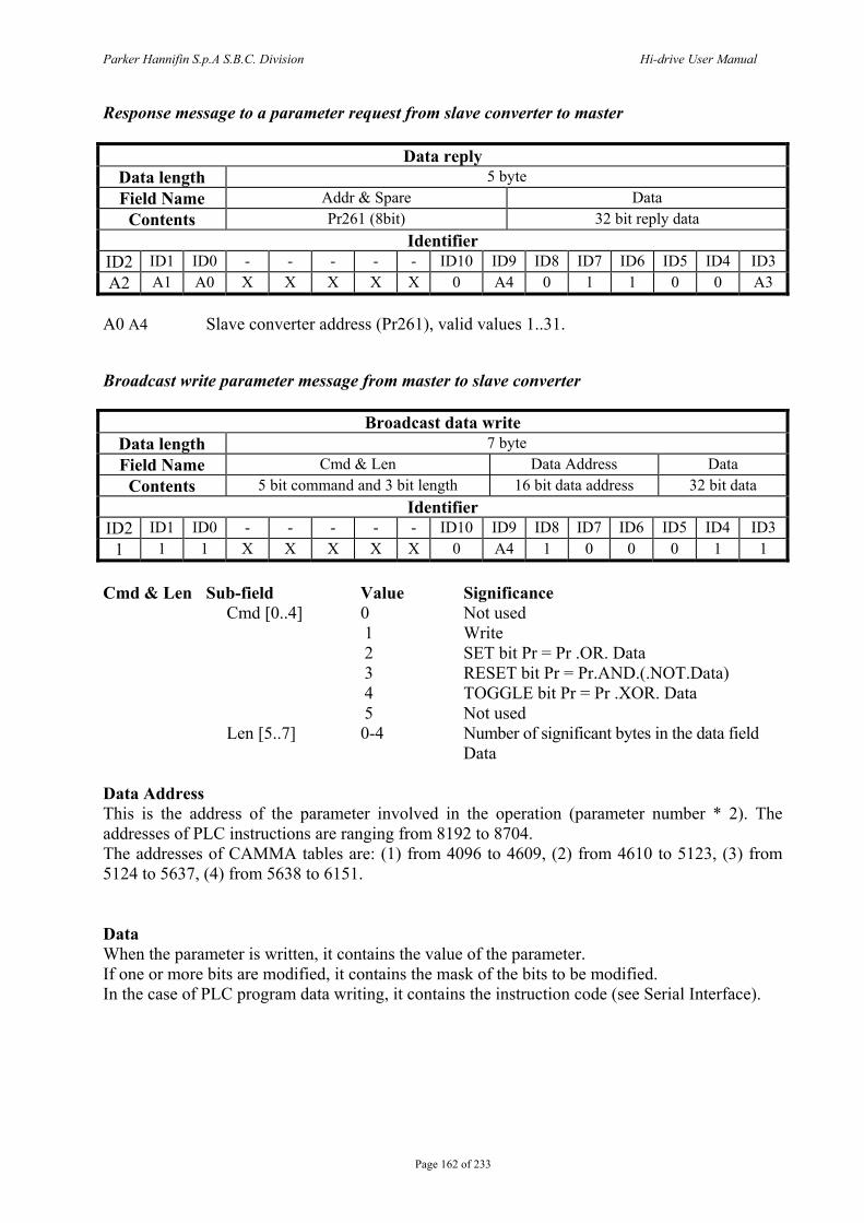
Parker Hannifin S.p.A S.B.C. Division Hi-drive User Manual
Page 162 of 233
Response message to a parameter request from slave converter to master
Data reply Data length 5 byte Field Name Addr & Spare Data
Contents Pr261 (8bit) 32 bit reply data Identifier
ID2 ID1 ID0 - - - - - ID10 ID9 ID8 ID7 ID6 ID5 ID4 ID3 A2 A1 A0 X X X X X 0 A4 0 1 1 0 0 A3
A0 A4 Slave converter address (Pr261), valid values 1..31. Broadcast write parameter message from master to slave converter
Broadcast data write Data length 7 byte Field Name Cmd & Len Data Address Data
Contents 5 bit command and 3 bit length 16 bit data address 32 bit data Identifier
ID2 ID1 ID0 - - - - - ID10 ID9 ID8 ID7 ID6 ID5 ID4 ID3 1 1 1 X X X X X 0 A4 1 0 0 0 1 1
Cmd & Len Sub-field Value Significance
Cmd [0..4] 0 Not used 1 Write 2 SET bit Pr = Pr .OR. Data 3 RESET bit Pr = Pr.AND.(.NOT.Data) 4 TOGGLE bit Pr = Pr .XOR. Data 5 Not used
Len [5..7] 0-4 Number of significant bytes in the data field Data
Data Address This is the address of the parameter involved in the operation (parameter number * 2). The addresses of PLC instructions are ranging from 8192 to 8704. The addresses of CAMMA tables are: (1) from 4096 to 4609, (2) from 4610 to 5123, (3) from 5124 to 5637, (4) from 5638 to 6151. Data When the parameter is written, it contains the value of the parameter. If one or more bits are modified, it contains the mask of the bits to be modified. In the case of PLC program data writing, it contains the instruction code (see Serial Interface).
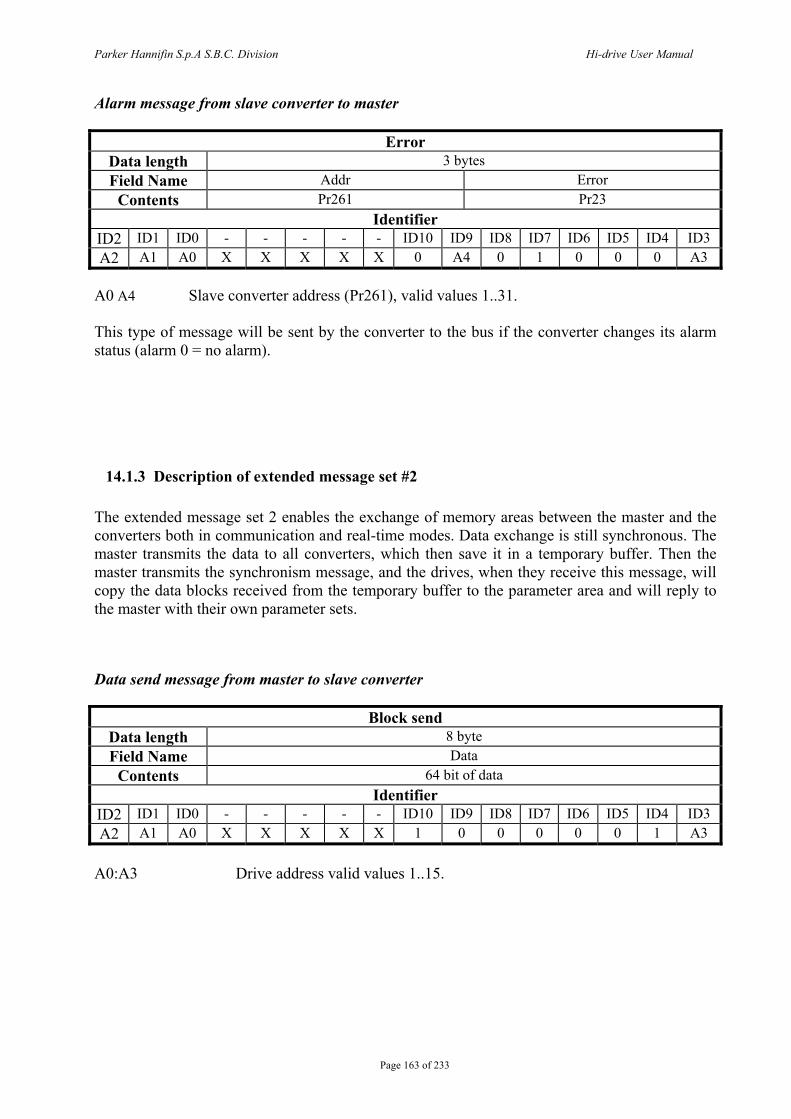
Parker Hannifin S.p.A S.B.C. Division Hi-drive User Manual
Page 163 of 233
Alarm message from slave converter to master
Error Data length 3 bytes Field Name Addr Error
Contents Pr261 Pr23 Identifier
ID2 ID1 ID0 - - - - - ID10 ID9 ID8 ID7 ID6 ID5 ID4 ID3 A2 A1 A0 X X X X X 0 A4 0 1 0 0 0 A3
A0 A4 Slave converter address (Pr261), valid values 1..31. This type of message will be sent by the converter to the bus if the converter changes its alarm status (alarm 0 = no alarm).
14.1.3 Description of extended message set #2 The extended message set 2 enables the exchange of memory areas between the master and the converters both in communication and real-time modes. Data exchange is still synchronous. The master transmits the data to all converters, which then save it in a temporary buffer. Then the master transmits the synchronism message, and the drives, when they receive this message, will copy the data blocks received from the temporary buffer to the parameter area and will reply to the master with their own parameter sets. Data send message from master to slave converter
Block send Data length 8 byte Field Name Data
Contents 64 bit of data Identifier
ID2 ID1 ID0 - - - - - ID10 ID9 ID8 ID7 ID6 ID5 ID4 ID3 A2 A1 A0 X X X X X 1 0 0 0 0 0 1 A3
A0:A3 Drive address valid values 1..15.

Parker Hannifin S.p.A S.B.C. Division Hi-drive User Manual
Page 164 of 233
Data synchronism message from master to slave converter
Block sync Data length 0 byte Field Name
Contents No data Identifier
ID2 ID1 ID0 - - - - - ID10 ID9 ID8 ID7 ID6 ID5 ID4 ID3 0 0 0 X X X X X 1 0 0 0 0 0 0 0
The data received are saved from Pr100 to Pr103, and parameters Pr104 to Pr107 are transmitted using the following message: Reply from slave converter to master
Block reply Data length 8 byte Field Name Data
Contents 64 bit of data Identifier
ID2 ID1 ID0 - - - - - ID10 ID9 ID8 ID7 ID6 ID5 ID4 ID3 A2 A1 A0 X X X X X 1 0 0 0 0 1 0 A3
A0:A3 Drive unit address valid values 1..15. Note 1: just like in real time mode, you can use bit 79.14, which is set to1 each time block sync is received via SBCCAN. Based on the above considerations, by simply adding a program to the Pico-PLC, you will be able to ensure that the communication between master and slave via CAN-bus is active. It is important to consider that, in this way, the communication via CAN-bus will be checked every 6.144 ms or multiple thereof (minimum time required to complete the scanning of the Pico-PLC program).
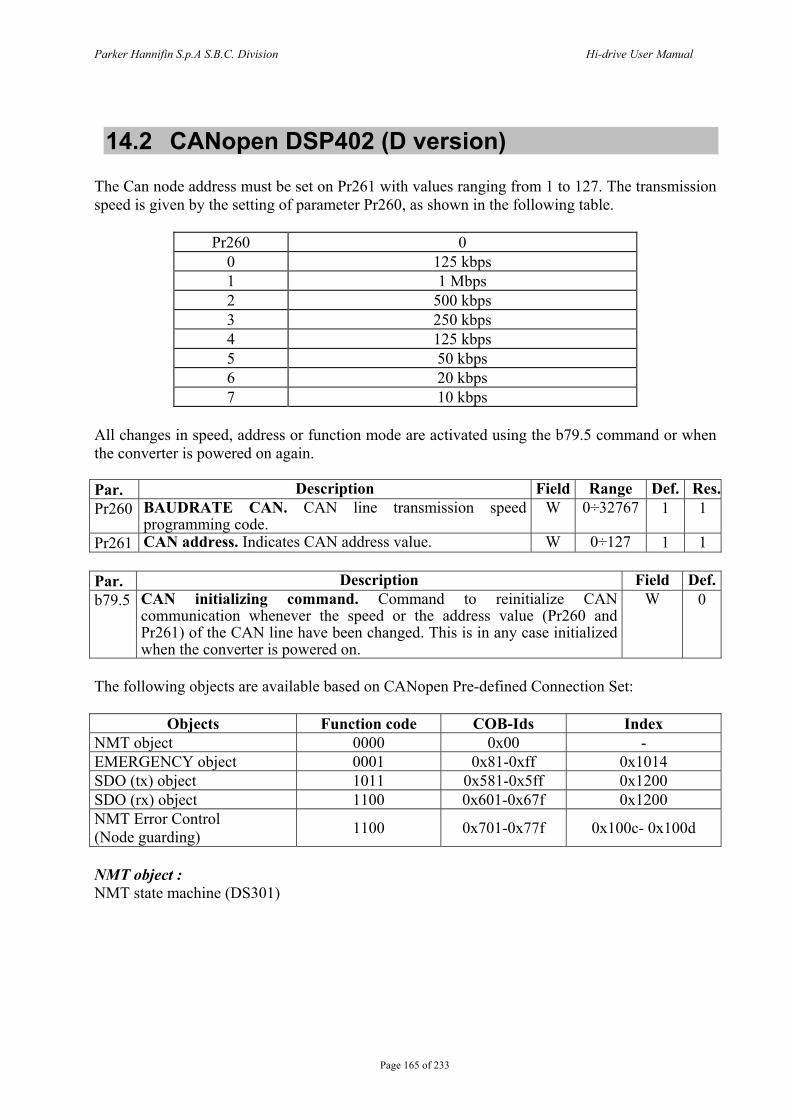
Parker Hannifin S.p.A S.B.C. Division Hi-drive User Manual
Page 165 of 233
14.2 CANopen DSP402 (D version) The Can node address must be set on Pr261 with values ranging from 1 to 127. The transmission speed is given by the setting of parameter Pr260, as shown in the following table.
Pr260 0 0 125 kbps 1 1 Mbps 2 500 kbps 3 250 kbps 4 125 kbps 5 50 kbps 6 20 kbps 7 10 kbps
All changes in speed, address or function mode are activated using the b79.5 command or when the converter is powered on again. Par. Description Field Range Def. Res.Pr260 BAUDRATE CAN. CAN line transmission speed
programming code. W 0÷32767 1 1
Pr261 CAN address. Indicates CAN address value. W 0÷127 1 1 Par. Description Field Def.b79.5 CAN initializing command. Command to reinitialize CAN
communication whenever the speed or the address value (Pr260 and Pr261) of the CAN line have been changed. This is in any case initialized when the converter is powered on.
W 0
The following objects are available based on CANopen Pre-defined Connection Set:
Objects Function code COB-Ids Index NMT object 0000 0x00 - EMERGENCY object 0001 0x81-0xff 0x1014 SDO (tx) object 1011 0x581-0x5ff 0x1200 SDO (rx) object 1100 0x601-0x67f 0x1200 NMT Error Control (Node guarding) 1100 0x701-0x77f 0x100c- 0x100d
NMT object : NMT state machine (DS301)
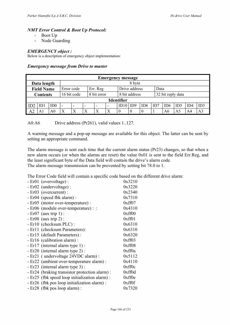
Parker Hannifin S.p.A S.B.C. Division Hi-drive User Manual
Page 166 of 233
NMT Error Control & Boot Up Protocol: - Boot Up - Node Guarding
EMERGENCY object : Below is a description of emergency object implementation: Emergency message from Drive to master
Emergency message Data length 8 byte Field Name Error code Err. Reg Drive address Data
Contents 16 bit code 8 bit error 8 bit address 32 bit reply data Identifier
ID2 ID1 ID0 - - - - - ID10 ID9 ID8 ID7 ID6 ID5 ID4 ID3 A2 A1 A0 X X X X X 0 0 0 1 A6 A5 A4 A3
A0:A6 Drive address (Pr261), valid values 1..127. A warning message and a pop-up message are available for this object. The latter can be sent by setting an appropriate command. The alarm message is sent each time that the current alarm status (Pr23) changes, so that when a new alarm occurs (or when the alarms are reset) the value 0x01 is sent to the field Err.Reg, and the least significant byte of the Data field will contain the drive’s alarm code. The alarm message transmission can be prevented by setting bit 78.0 to 1. The Error Code field will contain a specific code based on the different drive alarm: - Er01 (overvoltage) : 0x3210 - Er02 (undervoltage) : 0x3220 - Er03 (overcurrent) : 0x2340 - Er04 (speed fbk alarm) : 0x7310 - Er05 (motor over-temperature) : 0xff07 - Er06 (module over-temperature) : : 0x4310 - Er07 (aux trip 1) : 0xff00 - Er08 (aux trip 2) : 0xff01 - Er10 (checksum PLC) : 0x6310 - Er11 (checksum Parameters): 0x6310 - Er15 (default Parameters) : 0x6320 - Er16 (calibration alarm) : 0xff03 - Er17 (internal alarm type 1) : 0xff08 - Er20 (internal alarm type 2) : 0xff0a - Er21 ( undervoltage 24VDC alarm) : 0x5112 - Er22 (ambient over-temperature alarm) : 0x4110 - Er23 (internal alarm type 3) : 0xff0c - Er24 (braking transistor protection alarm) : 0xff0d - Er25 (fbk speed loop initialization alarm) : 0xff0e - Er26 (fbk pos loop initialization alarm) : 0xff0f - Er28 (fbk pos loop alarm) : 0x7320

Parker Hannifin S.p.A S.B.C. Division Hi-drive User Manual
Page 167 of 233
When alarms are reset with b42.10, Error code field will be 0x0000. A user pop-up message can be sent by setting command b79.12 to 1. In this case, the Error Code field will be 0xFF09 and the Data field will contain the value in Pr108:109. b 79.12 will be reset to 0 once the message has been sent. SDO(tx/rx) object In the CANopen implementation an SDO channel is available (standard cob-id) with a changeable timeout value mapped at the index 0x2020 as Unsigned 16 with a default value of 5000 (1 unit 1.024 msec). Both standard guarding protocols are available , Node guarding and heartbeat (the two cannot exist in the same time) Heartbeat is activated when a producer heartbeat time is set different from 0. Three PDO channels PDO 1,2,4 from the predefined standard connection set are available PDO 1 and 2 are serviced by a cyclic routine executed every 2.048 msec and they are remappable (elements of 2 or 4 bytes can be mapped) the RTR is allowed event time and inhibit time are active they can handle synchronous requests serviced every 2.048 msec or they can be handled as event driven. PDO 4 is the PDO channel used for strictly realtime operation as controlling motor trajectory or position loop (the PDO is synchronous type 1) no RTR is allowed and a restricted set of parameters can be mapped , in particular: PDO 4 rx : [0x6040] control word [0x60c1][1] position reference in counts [0x60c1][2] velocity reference in counts/sec [0x60c1][3] velocity reference in rpm PDO 4 tx : [0x6041] status word [0x6063] position feedback in counts [0x6064] position feedback in counts (normally in user unit in this case as
well in counts) [0x2060] Word composed with digital input and aux analog input . b0: In0 b1: In1 b2: In2 b3: In3 b4: enable b5: In4 b6...b15 Analog input aux. Life guarding protocol is implemented and can be activated writing life time factor and guard time besides a missing guarding event ,life guarding protocol can be triggered by a missing sync (if b79.8=1) or a bus-off condition. In any case state machine present state of ds301 communication can be changed according to what is set in the object 0x1029 ‘error behaviour’ (0 enter pre-operational, 1 no change, 2 stop). Note NMT commands are handled every 1.024 msec, so subsequent commands should be sent to the drive not closer than 1.204 msec including broadcast NMT commands.
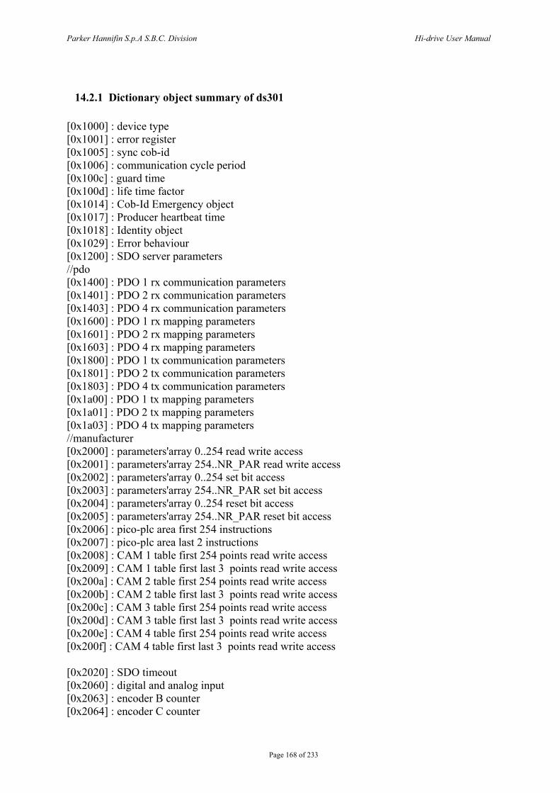
Parker Hannifin S.p.A S.B.C. Division Hi-drive User Manual
Page 168 of 233
14.2.1 Dictionary object summary of ds301 [0x1000] : device type [0x1001] : error register [0x1005] : sync cob-id [0x1006] : communication cycle period [0x100c] : guard time [0x100d] : life time factor [0x1014] : Cob-Id Emergency object [0x1017] : Producer heartbeat time [0x1018] : Identity object [0x1029] : Error behaviour [0x1200] : SDO server parameters //pdo [0x1400] : PDO 1 rx communication parameters [0x1401] : PDO 2 rx communication parameters [0x1403] : PDO 4 rx communication parameters [0x1600] : PDO 1 rx mapping parameters [0x1601] : PDO 2 rx mapping parameters [0x1603] : PDO 4 rx mapping parameters [0x1800] : PDO 1 tx communication parameters [0x1801] : PDO 2 tx communication parameters [0x1803] : PDO 4 tx communication parameters [0x1a00] : PDO 1 tx mapping parameters [0x1a01] : PDO 2 tx mapping parameters [0x1a03] : PDO 4 tx mapping parameters //manufacturer [0x2000] : parameters'array 0..254 read write access [0x2001] : parameters'array 254..NR_PAR read write access [0x2002] : parameters'array 0..254 set bit access [0x2003] : parameters'array 254..NR_PAR set bit access [0x2004] : parameters'array 0..254 reset bit access [0x2005] : parameters'array 254..NR_PAR reset bit access [0x2006] : pico-plc area first 254 instructions [0x2007] : pico-plc area last 2 instructions [0x2008] : CAM 1 table first 254 points read write access [0x2009] : CAM 1 table first last 3 points read write access [0x200a] : CAM 2 table first 254 points read write access [0x200b] : CAM 2 table first last 3 points read write access [0x200c] : CAM 3 table first 254 points read write access [0x200d] : CAM 3 table first last 3 points read write access [0x200e] : CAM 4 table first 254 points read write access [0x200f] : CAM 4 table first last 3 points read write access [0x2020] : SDO timeout [0x2060] : digital and analog input [0x2063] : encoder B counter [0x2064] : encoder C counter

Parker Hannifin S.p.A S.B.C. Division Hi-drive User Manual
Page 169 of 233
[0x2065] : I° timer in msec.; it’s activated when the motor speed is equal to 0rpm (by the 7, 10 or 11 transition of the state machine), when the timer finishes, the bit b78.4 is set to 1, and it’s possible to use it to management the motor brake. [0x2066] : II° timer in msec.; it’s activated when the motor speed is equal to 0rpm (by the 7, 10 or 11 transition of the state machine), when the timer finishes, the drive is disabled. So the II° timer [0x2066] must be longer of I° timer [0x2065].
7
Quick stopactive
Switch On disabled10
11
I° Timer(oggetto 0x 2065 )
II° Timer(oggetto 0x 2066 )
b70.4=1
Drive disabled
Transition
MotorBrake
0 rpm
As a general rule, sub_index 0 of indexes 0x2000..0x200F represents the number of the sub_indexes available, and the subsequent (1..N) sub_indexes represent the parameter number concerned +1. Sub_index 1 Pr[0] Sub_index 2 Pr[1] …. Sub_index n+1 Pr[n] Example of device memory access by SDO: Write Pr80 to the drive: You will need to write the object by SDO with index-sub_index 0x2000-0x51 (80+1). If the number of bytes written is greater than two, the operation will also change the parameter Pr81.
Read Pr60 from the drive: You will need to read the object by SDO with index-sub_index 0x2000-0x3d (60+1). The value returned will have a length of 4 bytes, the most significant of which will contain Pr61. If they are not needed, they can simply be discarded. Set bit 4 of Pr40: You will need to write the object by SDO with index-sub_index 0x2002-0x29 (40+1) with the value (0x0010) that represents in binary the bits involved in the operation, in our case bit 4.
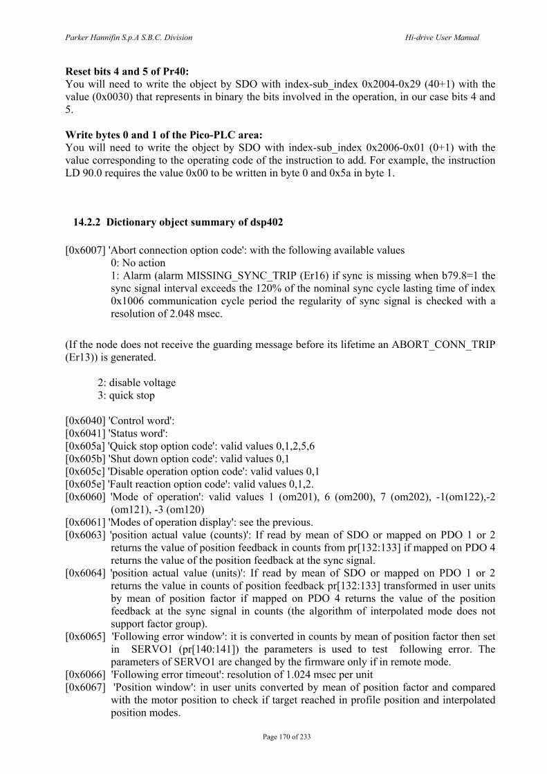
Parker Hannifin S.p.A S.B.C. Division Hi-drive User Manual
Page 170 of 233
Reset bits 4 and 5 of Pr40: You will need to write the object by SDO with index-sub_index 0x2004-0x29 (40+1) with the value (0x0030) that represents in binary the bits involved in the operation, in our case bits 4 and 5. Write bytes 0 and 1 of the Pico-PLC area: You will need to write the object by SDO with index-sub_index 0x2006-0x01 (0+1) with the value corresponding to the operating code of the instruction to add. For example, the instruction LD 90.0 requires the value 0x00 to be written in byte 0 and 0x5a in byte 1.
14.2.2 Dictionary object summary of dsp402 [0x6007] 'Abort connection option code': with the following available values
0: No action 1: Alarm (alarm MISSING_SYNC_TRIP (Er16) if sync is missing when b79.8=1 the
sync signal interval exceeds the 120% of the nominal sync cycle lasting time of index 0x1006 communication cycle period the regularity of sync signal is checked with a resolution of 2.048 msec.
(If the node does not receive the guarding message before its lifetime an ABORT_CONN_TRIP (Er13)) is generated. 2: disable voltage 3: quick stop [0x6040] 'Control word': [0x6041] 'Status word': [0x605a] 'Quick stop option code': valid values 0,1,2,5,6 [0x605b] 'Shut down option code': valid values 0,1 [0x605c] 'Disable operation option code': valid values 0,1 [0x605e] 'Fault reaction option code': valid values 0,1,2. [0x6060] 'Mode of operation': valid values 1 (om201), 6 (om200), 7 (om202), -1(om122),-2
(om121), -3 (om120) [0x6061] 'Modes of operation display': see the previous. [0x6063] 'position actual value (counts)': If read by mean of SDO or mapped on PDO 1 or 2
returns the value of position feedback in counts from pr[132:133] if mapped on PDO 4 returns the value of the position feedback at the sync signal.
[0x6064] 'position actual value (units)': If read by mean of SDO or mapped on PDO 1 or 2 returns the value in counts of position feedback pr[132:133] transformed in user units by mean of position factor if mapped on PDO 4 returns the value of the position feedback at the sync signal in counts (the algorithm of interpolated mode does not support factor group).
[0x6065] 'Following error window': it is converted in counts by mean of position factor then set in SERVO1 (pr[140:141]) the parameters is used to test following error. The parameters of SERVO1 are changed by the firmware only if in remote mode.
[0x6066] 'Following error timeout': resolution of 1.024 msec per unit [0x6067] 'Position window': in user units converted by mean of position factor and compared
with the motor position to check if target reached in profile position and interpolated position modes.
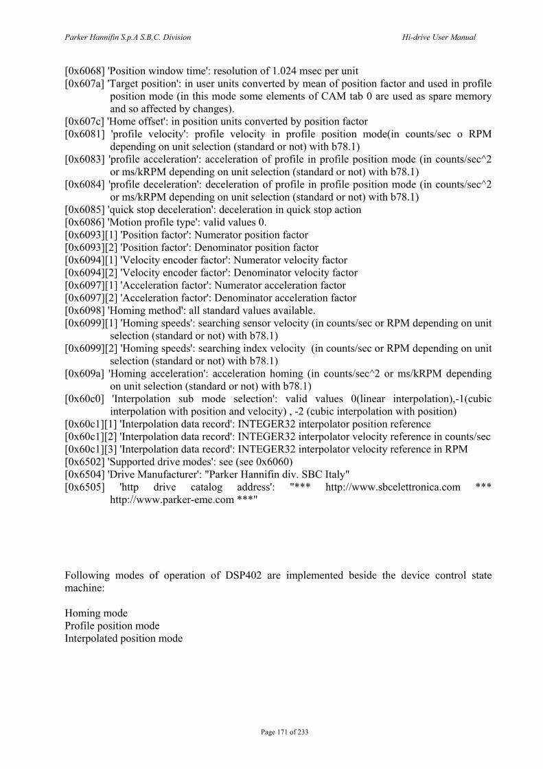
Parker Hannifin S.p.A S.B.C. Division Hi-drive User Manual
Page 171 of 233
[0x6068] 'Position window time': resolution of 1.024 msec per unit [0x607a] 'Target position': in user units converted by mean of position factor and used in profile
position mode (in this mode some elements of CAM tab 0 are used as spare memory and so affected by changes).
[0x607c] 'Home offset': in position units converted by position factor [0x6081] 'profile velocity': profile velocity in profile position mode(in counts/sec o RPM
depending on unit selection (standard or not) with b78.1) [0x6083] 'profile acceleration': acceleration of profile in profile position mode (in counts/sec^2
or ms/kRPM depending on unit selection (standard or not) with b78.1) [0x6084] 'profile deceleration': deceleration of profile in profile position mode (in counts/sec^2
or ms/kRPM depending on unit selection (standard or not) with b78.1) [0x6085] 'quick stop deceleration': deceleration in quick stop action [0x6086] 'Motion profile type': valid values 0. [0x6093][1] 'Position factor': Numerator position factor [0x6093][2] 'Position factor': Denominator position factor [0x6094][1] 'Velocity encoder factor': Numerator velocity factor [0x6094][2] 'Velocity encoder factor': Denominator velocity factor [0x6097][1] 'Acceleration factor': Numerator acceleration factor [0x6097][2] 'Acceleration factor': Denominator acceleration factor [0x6098] 'Homing method': all standard values available. [0x6099][1] 'Homing speeds': searching sensor velocity (in counts/sec or RPM depending on unit
selection (standard or not) with b78.1) [0x6099][2] 'Homing speeds': searching index velocity (in counts/sec or RPM depending on unit
selection (standard or not) with b78.1) [0x609a] 'Homing acceleration': acceleration homing (in counts/sec^2 or ms/kRPM depending
on unit selection (standard or not) with b78.1) [0x60c0] 'Interpolation sub mode selection': valid values 0(linear interpolation),-1(cubic
interpolation with position and velocity) , -2 (cubic interpolation with position) [0x60c1][1] 'Interpolation data record': INTEGER32 interpolator position reference [0x60c1][2] 'Interpolation data record': INTEGER32 interpolator velocity reference in counts/sec [0x60c1][3] 'Interpolation data record': INTEGER32 interpolator velocity reference in RPM [0x6502] 'Supported drive modes': see (see 0x6060) [0x6504] 'Drive Manufacturer': "Parker Hannifin div. SBC Italy" [0x6505] 'http drive catalog address': "*** http://www.sbcelettronica.com ***
http://www.parker-eme.com ***" Following modes of operation of DSP402 are implemented beside the device control state machine: Homing mode Profile position mode Interpolated position mode
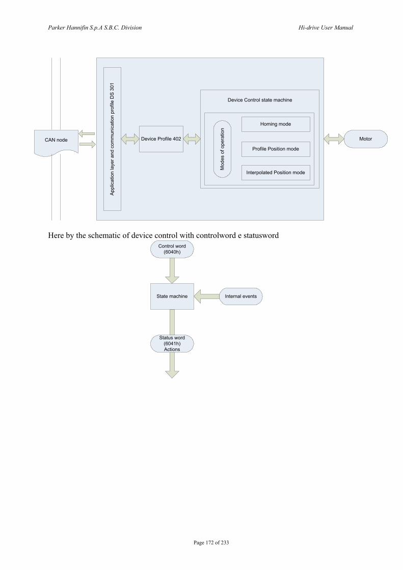
Parker Hannifin S.p.A S.B.C. Division Hi-drive User Manual
Page 172 of 233
CAN node
Appl
icat
ion
laye
r and
com
mun
icat
ion
prof
ile D
S 30
1
Device Profile 402
Device Control state machine
Motor
Homing mode
Profile Position mode
Interpolated Position mode
Mod
es o
f ope
ratio
n
Here by the schematic of device control with controlword e statusword
State machine Internal events
Control word(6040h)
Status word (6041h)Actions
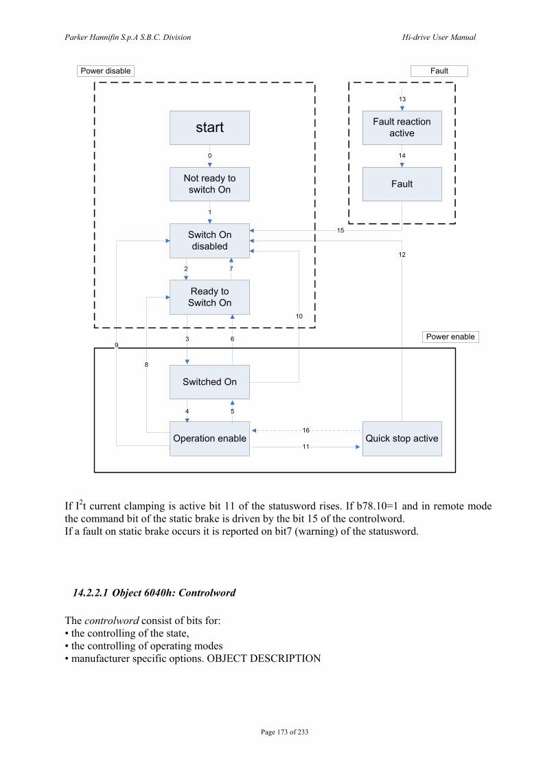
Parker Hannifin S.p.A S.B.C. Division Hi-drive User Manual
Page 173 of 233
start
Not ready to switch On
Switch On disabled
Ready to Switch On
Switched On
Operation enable
Fault reaction active
Fault
Quick stop active
0
1
2 7
3 6
4 5
11
16
8
9
10
12
15
14
13
Power disable Fault
Power enable
If I2t current clamping is active bit 11 of the statusword rises. If b78.10=1 and in remote mode the command bit of the static brake is driven by the bit 15 of the controlword. If a fault on static brake occurs it is reported on bit7 (warning) of the statusword.
14.2.2.1 Object 6040h: Controlword The controlword consist of bits for: • the controlling of the state, • the controlling of operating modes • manufacturer specific options. OBJECT DESCRIPTION
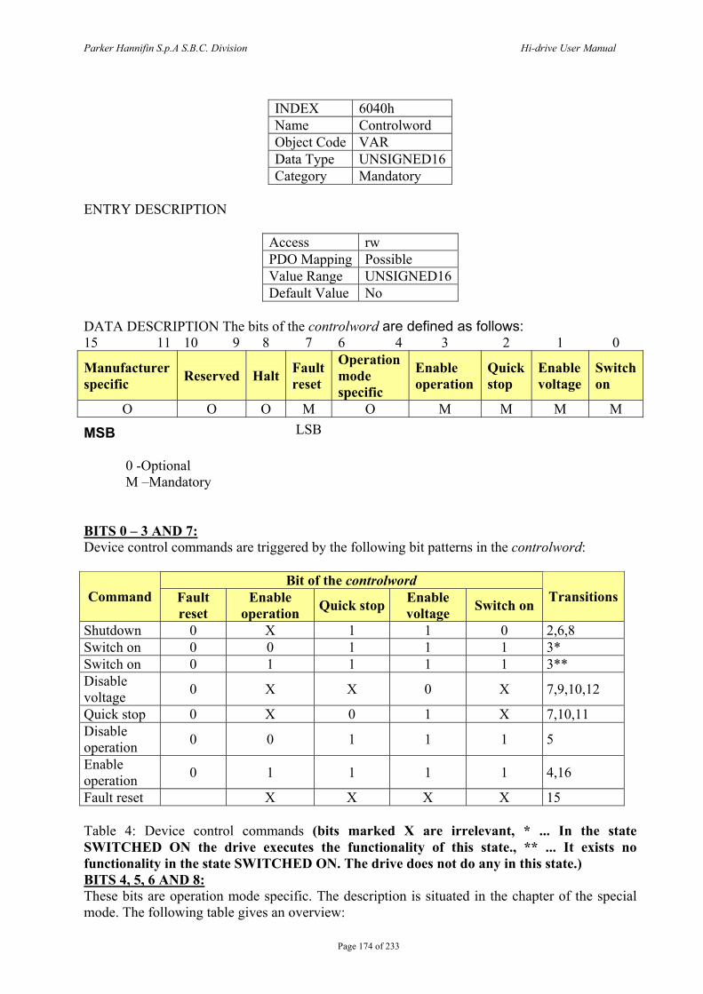
Parker Hannifin S.p.A S.B.C. Division Hi-drive User Manual
Page 174 of 233
INDEX 6040h Name Controlword Object Code VAR Data Type UNSIGNED16 Category Mandatory
ENTRY DESCRIPTION
Access rw PDO Mapping Possible Value Range UNSIGNED16 Default Value No
DATA DESCRIPTION The bits of the controlword are defined as follows: 15 11 10 9 8 7 6 4 3 2 1 0
Manufacturer specific Reserved Halt Fault
reset
Operation mode specific
Enable operation
Quick stop
Enable voltage
Switch on
O O O M O M M M M
MSB LSB
0 -Optional M –Mandatory
BITS 0 – 3 AND 7: Device control commands are triggered by the following bit patterns in the controlword:
Bit of the controlword Command Fault
reset Enable
operation Quick stop Enable voltage Switch on Transitions
Shutdown 0 X 1 1 0 2,6,8 Switch on 0 0 1 1 1 3* Switch on 0 1 1 1 1 3** Disable voltage 0 X X 0 X 7,9,10,12
Quick stop 0 X 0 1 X 7,10,11 Disable operation 0 0 1 1 1 5
Enable operation 0 1 1 1 1 4,16
Fault reset X X X X 15 Table 4: Device control commands (bits marked X are irrelevant, * ... In the state SWITCHED ON the drive executes the functionality of this state., ** ... It exists no functionality in the state SWITCHED ON. The drive does not do any in this state.) BITS 4, 5, 6 AND 8: These bits are operation mode specific. The description is situated in the chapter of the special mode. The following table gives an overview:

Parker Hannifin S.p.A S.B.C. Division Hi-drive User Manual
Page 175 of 233
Operation mode Bit Velocity mode Profile velocity mode Profile torque mode
4 rfg enable reserved reserved 5 rfg unlock reserved reserved 6 rfg use ref reserved reserved 8 Halt Halt Halt
Table 5: Mode specific bits in the controlword BITS 9, 10: These bits are reserved for further use. They are inactive by setting to zero. If they have no special function, they must be set to zero. BITS 11, 12, 13, 14 AND 15: These bits are manufacturer specific.
14.2.2.2 Object 6041h: Statusword The statusword indicates the current state of the drive. No bits are latched. The statusword consist of bits for: • the current state of the drive, • the operating state of the mode and • manufacturer specific options.
OBJECT DESCRIPTION
INDEX 6041h Name Statusword Object Code VAR Data Type UNSIGNED16 Category Mandatory
ENTRY DESCRIPTION
Access ro PDO Mapping Possible Value Range UNSIGNED16 Default Value No
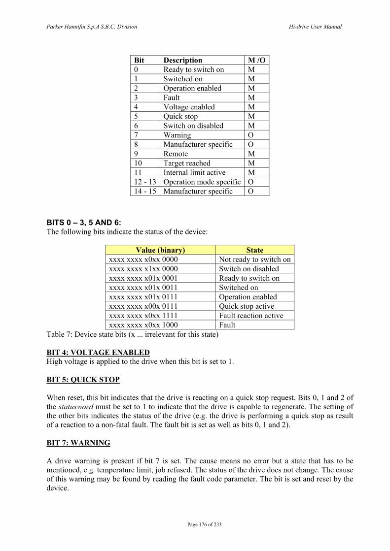
Parker Hannifin S.p.A S.B.C. Division Hi-drive User Manual
Page 176 of 233
Bit Description M /O 0 Ready to switch on M 1 Switched on M 2 Operation enabled M 3 Fault M 4 Voltage enabled M 5 Quick stop M 6 Switch on disabled M 7 Warning O 8 Manufacturer specific O 9 Remote M 10 Target reached M 11 Internal limit active M 12 - 13 Operation mode specific O 14 - 15 Manufacturer specific O
BITS 0 – 3, 5 AND 6: The following bits indicate the status of the device:
Value (binary) State xxxx xxxx x0xx 0000 Not ready to switch on xxxx xxxx x1xx 0000 Switch on disabled xxxx xxxx x01x 0001 Ready to switch on xxxx xxxx x01x 0011 Switched on xxxx xxxx x01x 0111 Operation enabled xxxx xxxx x00x 0111 Quick stop active xxxx xxxx x0xx 1111 Fault reaction active xxxx xxxx x0xx 1000 Fault
Table 7: Device state bits (x ... irrelevant for this state) BIT 4: VOLTAGE ENABLED High voltage is applied to the drive when this bit is set to 1. BIT 5: QUICK STOP When reset, this bit indicates that the drive is reacting on a quick stop request. Bits 0, 1 and 2 of the statusword must be set to 1 to indicate that the drive is capable to regenerate. The setting of the other bits indicates the status of the drive (e.g. the drive is performing a quick stop as result of a reaction to a non-fatal fault. The fault bit is set as well as bits 0, 1 and 2). BIT 7: WARNING A drive warning is present if bit 7 is set. The cause means no error but a state that has to be mentioned, e.g. temperature limit, job refused. The status of the drive does not change. The cause of this warning may be found by reading the fault code parameter. The bit is set and reset by the device.
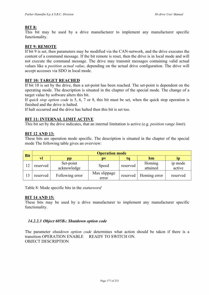
Parker Hannifin S.p.A S.B.C. Division Hi-drive User Manual
Page 177 of 233
BIT 8: This bit may be used by a drive manufacturer to implement any manufacturer specific functionality. BIT 9: REMOTE If bit 9 is set, then parameters may be modified via the CAN-network, and the drive executes the content of a command message. If the bit remote is reset, then the drive is in local mode and will not execute the command message. The drive may transmit messages containing valid actual values like a position actual value, depending on the actual drive configuration. The drive will accept accesses via SDO in local mode. BIT 10: TARGET REACHED If bit 10 is set by the drive, then a set-point has been reached. The set-point is dependent on the operating mode. The description is situated in the chapter of the special mode. The change of a target value by software alters this bit. If quick stop option code is 5, 6, 7 or 8, this bit must be set, when the quick stop operation is finished and the drive is halted. If halt occurred and the drive has halted then this bit is set too. BIT 11: INTERNAL LIMIT ACTIVE This bit set by the drive indicates, that an internal limitation is active (e.g. position range limit). BIT 12 AND 13: These bits are operation mode specific. The description is situated in the chapter of the special mode The following table gives an overview:
Operation mode Bit vl pp pv tq hm ip
12 reserved Set-point acknowledge Speed reserved Homing
attained ip mode active
13 reserved Following error Max slippage error reserved Homing error reserved
Table 8: Mode specific bits in the statusword BIT 14 AND 15: These bits may be used by a drive manufacturer to implement any manufacturer specific functionality.
14.2.2.3 Object 605Bh: Shutdown option code The parameter shutdown option code determines what action should be taken if there is a transition OPERATION ENABLE READY TO SWITCH ON. OBJECT DESCRIPTION
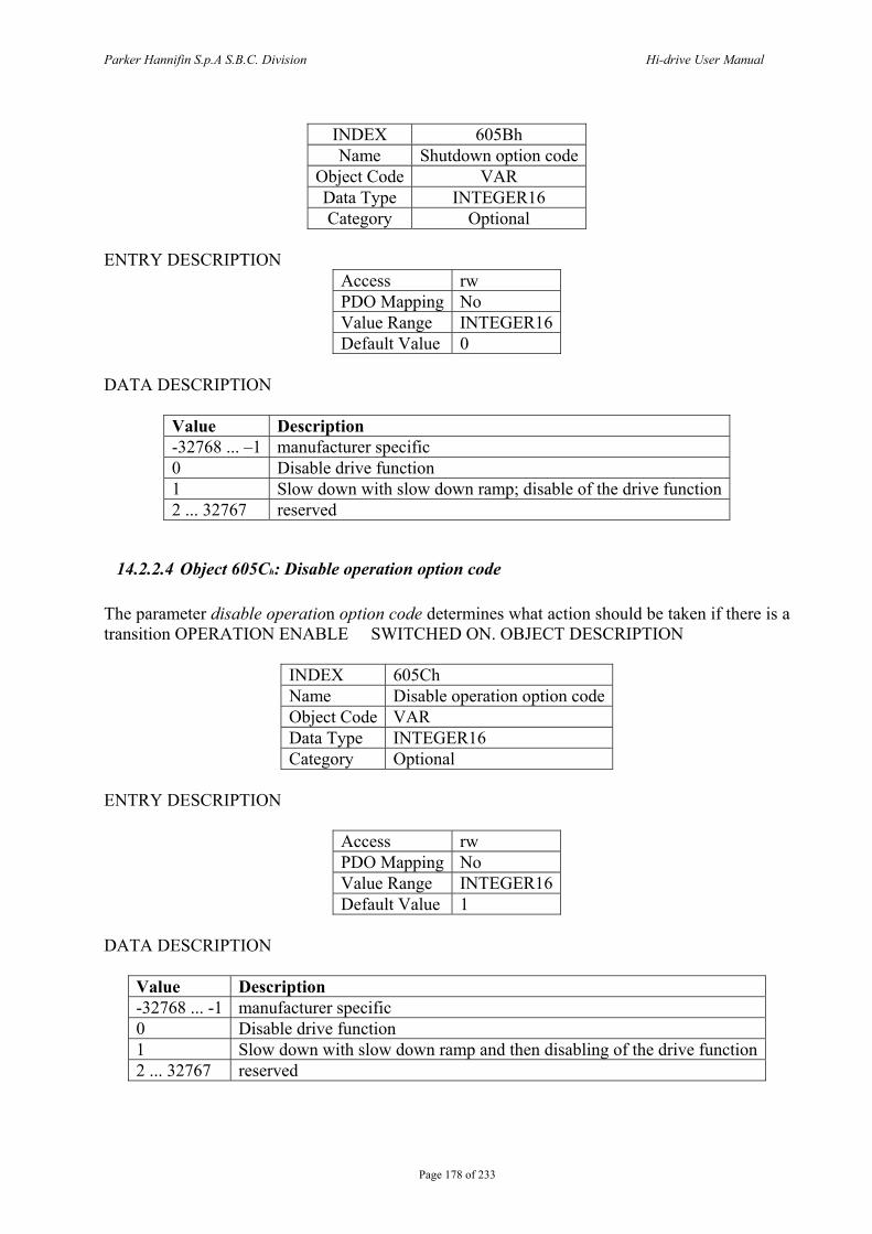
Parker Hannifin S.p.A S.B.C. Division Hi-drive User Manual
Page 178 of 233
INDEX 605Bh Name Shutdown option code
Object Code VAR Data Type INTEGER16 Category Optional
ENTRY DESCRIPTION
Access rw PDO Mapping No Value Range INTEGER16 Default Value 0
DATA DESCRIPTION
Value Description -32768 ... –1 manufacturer specific 0 Disable drive function 1 Slow down with slow down ramp; disable of the drive function 2 ... 32767 reserved
14.2.2.4 Object 605Ch: Disable operation option code The parameter disable operation option code determines what action should be taken if there is a transition OPERATION ENABLE SWITCHED ON. OBJECT DESCRIPTION
INDEX 605Ch Name Disable operation option code Object Code VAR Data Type INTEGER16 Category Optional
ENTRY DESCRIPTION
Access rw PDO Mapping No Value Range INTEGER16 Default Value 1
DATA DESCRIPTION
Value Description -32768 ... -1 manufacturer specific 0 Disable drive function 1 Slow down with slow down ramp and then disabling of the drive function 2 ... 32767 reserved
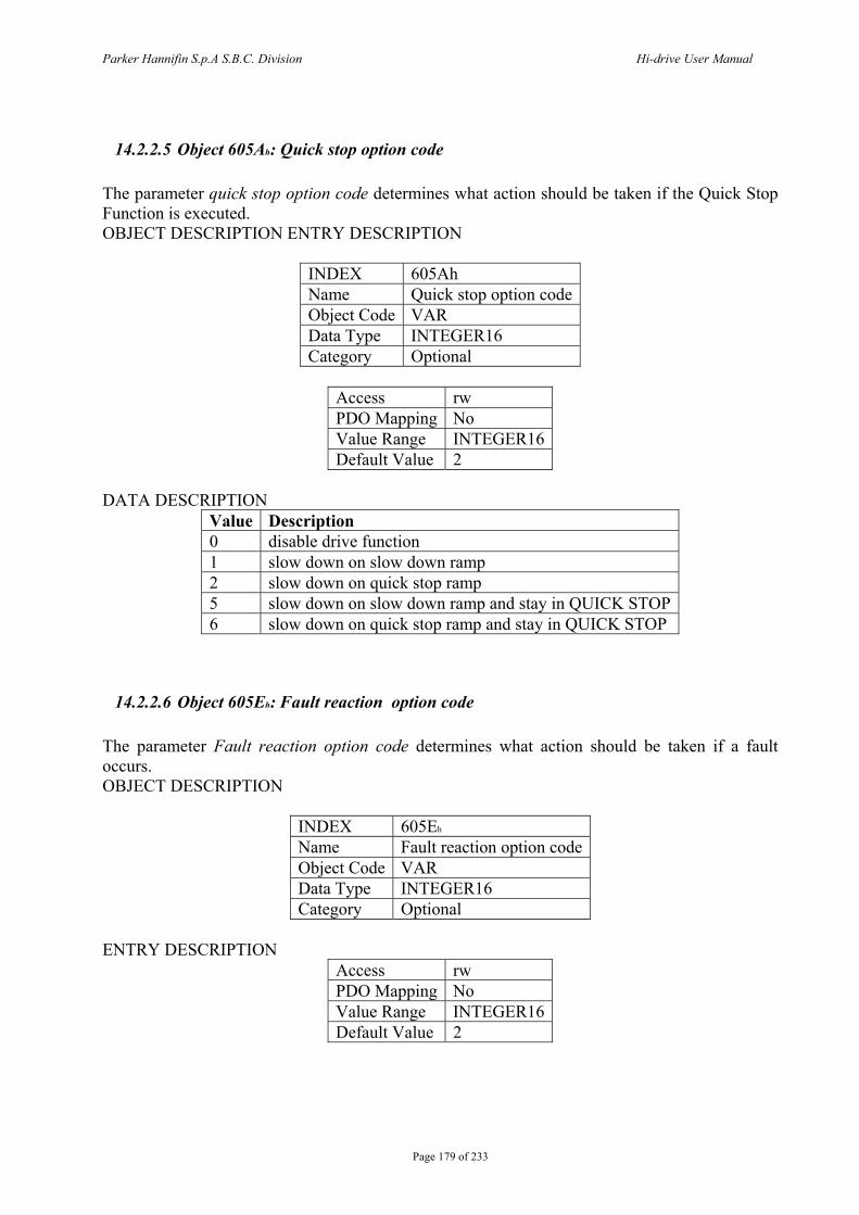
Parker Hannifin S.p.A S.B.C. Division Hi-drive User Manual
Page 179 of 233
14.2.2.5 Object 605Ah: Quick stop option code The parameter quick stop option code determines what action should be taken if the Quick Stop Function is executed. OBJECT DESCRIPTION ENTRY DESCRIPTION
INDEX 605Ah Name Quick stop option code Object Code VAR Data Type INTEGER16 Category Optional
Access rw PDO Mapping No Value Range INTEGER16 Default Value 2
DATA DESCRIPTION
Value Description 0 disable drive function 1 slow down on slow down ramp 2 slow down on quick stop ramp 5 slow down on slow down ramp and stay in QUICK STOP 6 slow down on quick stop ramp and stay in QUICK STOP
14.2.2.6 Object 605Eh: Fault reaction option code The parameter Fault reaction option code determines what action should be taken if a fault occurs. OBJECT DESCRIPTION
INDEX 605Eh
Name Fault reaction option code Object Code VAR Data Type INTEGER16 Category Optional
ENTRY DESCRIPTION
Access rw PDO Mapping No Value Range INTEGER16 Default Value 2
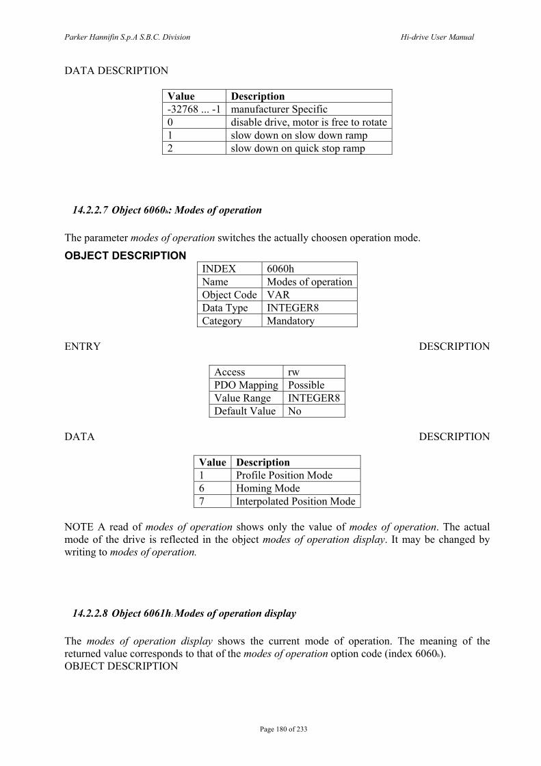
Parker Hannifin S.p.A S.B.C. Division Hi-drive User Manual
Page 180 of 233
DATA DESCRIPTION
Value Description -32768 ... -1 manufacturer Specific 0 disable drive, motor is free to rotate 1 slow down on slow down ramp 2 slow down on quick stop ramp
14.2.2.7 Object 6060h: Modes of operation The parameter modes of operation switches the actually choosen operation mode.
OBJECT DESCRIPTION INDEX 6060h Name Modes of operation Object Code VAR Data Type INTEGER8 Category Mandatory
ENTRY DESCRIPTION
Access rw PDO Mapping Possible Value Range INTEGER8 Default Value No
DATA DESCRIPTION
Value Description 1 Profile Position Mode 6 Homing Mode 7 Interpolated Position Mode
NOTE A read of modes of operation shows only the value of modes of operation. The actual mode of the drive is reflected in the object modes of operation display. It may be changed by writing to modes of operation.
14.2.2.8 Object 6061h: Modes of operation display The modes of operation display shows the current mode of operation. The meaning of the returned value corresponds to that of the modes of operation option code (index 6060h). OBJECT DESCRIPTION
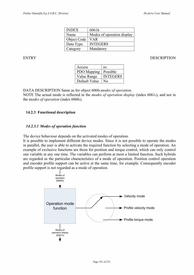
Parker Hannifin S.p.A S.B.C. Division Hi-drive User Manual
Page 181 of 233
INDEX 6061h Name Modes of operation display Object Code VAR Data Type INTEGER8 Category Mandatory
ENTRY DESCRIPTION
Access ro PDO Mapping Possible Value Range INTEGER8 Default Value No
DATA DESCRIPTION Same as for object 6060h modes of operation. NOTE The actual mode is reflected in the modes of operation display (index 6061h), and not in the modes of operation (index 6060h).
14.2.3 Functional description
14.2.3.1 Modes of operation function The device behaviour depends on the activated modes of operation. It is possible to implement different device modes. Since it is not possible to operate the modes in parallel, the user is able to activate the required function by selecting a mode of operation. An example of exclusive functions are those for position and torque control, which can only control one variable at any one time. The variables can perform at most a limited function. Such hybrids are regarded as the particular characteristics of a mode of operation. Position control operation and encoder profile support can be active at the same time, for example. Consequently encoder profile support is not regarded as a mode of operation.
Operation mode function
Modes of operation (6060h)
Modes of operation display
(6061h)
Velocity mode
Profile velocity mode
Profile torque mode
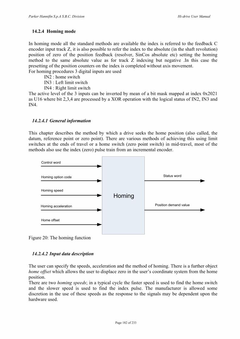
Parker Hannifin S.p.A S.B.C. Division Hi-drive User Manual
Page 182 of 233
14.2.4 Homing mode In homing mode all the standard methods are available the index is referred to the feedback C encoder input track Z, it is also possible to refer the index to the absolute (in the shaft revolution) position of zero of the position feedback (resolver, SinCos absolute etc) setting the homing method to the same absolute value as for track Z indexing but negative .In this case the presetting of the position counters on the index is completed without axis movement. For homing procedures 3 digital inputs are used IN2 : home switch IN3 : Left limit switch IN4 : Right limit switch The active level of the 3 inputs can be inverted by mean of a bit mask mapped at index 0x2021 as U16 where bit 2,3,4 are processed by a XOR operation with the logical status of IN2, IN3 and IN4.
14.2.4.1 General information This chapter describes the method by which a drive seeks the home position (also called, the datum, reference point or zero point). There are various methods of achieving this using limit switches at the ends of travel or a home switch (zero point switch) in mid-travel, most of the methods also use the index (zero) pulse train from an incremental encoder.
Status word
Position demand value
Control word
Homing option code
Homing speed
Homing acceleration
Home offset
Homing
Figure 20: The homing function
14.2.4.2 Input data description The user can specify the speeds, acceleration and the method of homing. There is a further object home offset which allows the user to displace zero in the user’s coordinate system from the home position. There are two homing speeds; in a typical cycle the faster speed is used to find the home switch and the slower speed is used to find the index pulse. The manufacturer is allowed some discretion in the use of these speeds as the response to the signals may be dependent upon the hardware used.
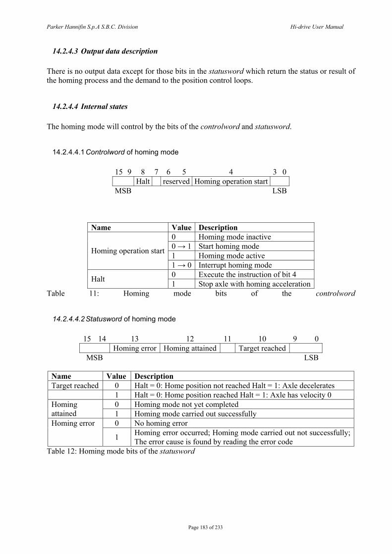
Parker Hannifin S.p.A S.B.C. Division Hi-drive User Manual
Page 183 of 233
14.2.4.3 Output data description There is no output data except for those bits in the statusword which return the status or result of the homing process and the demand to the position control loops.
14.2.4.4 Internal states The homing mode will control by the bits of the controlword and statusword.
14.2.4.4.1 Controlword of homing mode
15 9 8 7 6 5 4 3 0 Halt reserved Homing operation start
MSB LSB
Name Value Description 0 Homing mode inactive 0 → 1 Start homing mode 1 Homing mode active Homing operation start
1 → 0 Interrupt homing mode 0 Execute the instruction of bit 4 Halt 1 Stop axle with homing acceleration
Table 11: Homing mode bits of the controlword
14.2.4.4.2 Statusword of homing mode
15 14 13 12 11 10 9 0 Homing error Homing attained Target reached
MSB LSB
Name Value Description Target reached 0 Halt = 0: Home position not reached Halt = 1: Axle decelerates 1 Halt = 0: Home position reached Halt = 1: Axle has velocity 0
0 Homing mode not yet completed Homing attained 1 Homing mode carried out successfully
0 No homing error Homing error
1 Homing error occurred; Homing mode carried out not successfully; The error cause is found by reading the error code
Table 12: Homing mode bits of the statusword
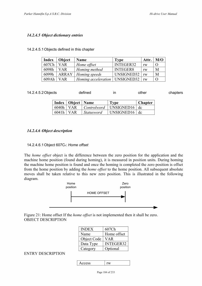
Parker Hannifin S.p.A S.B.C. Division Hi-drive User Manual
Page 184 of 233
14.2.4.5 Object dictionary entries
14.2.4.5.1 Objects defined in this chapter
Index Object Name Type Attr. M/O 607Ch VAR Home offset INTEGER32 rw O 6098h VAR Homing method INTEGER8 rw M 6099h ARRAY Homing speeds UNSIGNED32 rw M 609Ah VAR Homing acceleration UNSIGNED32 rw O
14.2.4.5.2 Objects defined in other chapters
Index Object Name Type Chapter 6040h VAR Controlword UNSIGNED16 dc 6041h VAR Statusword UNSIGNED16 dc
14.2.4.6 Object description
14.2.4.6.1 Object 607Ch: Home offset The home offset object is the difference between the zero position for the application and the machine home position (found during homing), it is measured in position units. During homing the machine home position is found and once the homing is completed the zero position is offset from the home position by adding the home offset to the home position. All subsequent absolute moves shall be taken relative to this new zero position. This is illustrated in the following diagram.
HOME OFFSET
Home position
Zero position
Figure 21: Home offset If the home offset is not implemented then it shall be zero. OBJECT DESCRIPTION
INDEX 607Ch Name Home offset Object Code VAR Data Type INTEGER32 Category Optional
ENTRY DESCRIPTION
Access rw
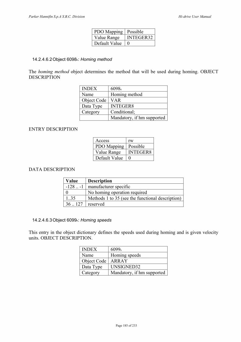
Parker Hannifin S.p.A S.B.C. Division Hi-drive User Manual
Page 185 of 233
PDO Mapping Possible Value Range INTEGER32 Default Value 0
14.2.4.6.2 Object 6098h: Homing method The homing method object determines the method that will be used during homing. OBJECT DESCRIPTION
INDEX 6098h
Name Homing method Object Code VAR Data Type INTEGER8 Category Conditional; Mandatory, if hm supported
ENTRY DESCRIPTION
Access rw PDO Mapping Possible Value Range INTEGER8 Default Value 0
DATA DESCRIPTION
Value Description -128 .. -1 manufacturer specific 0 No homing operation required 1..35 Methods 1 to 35 (see the functional description) 36 .. 127 reserved
14.2.4.6.3 Object 6099h: Homing speeds This entry in the object dictionary defines the speeds used during homing and is given velocity units. OBJECT DESCRIPTION.
INDEX 6099h
Name Homing speeds Object Code ARRAY Data Type UNSIGNED32 Category Mandatory, if hm supported
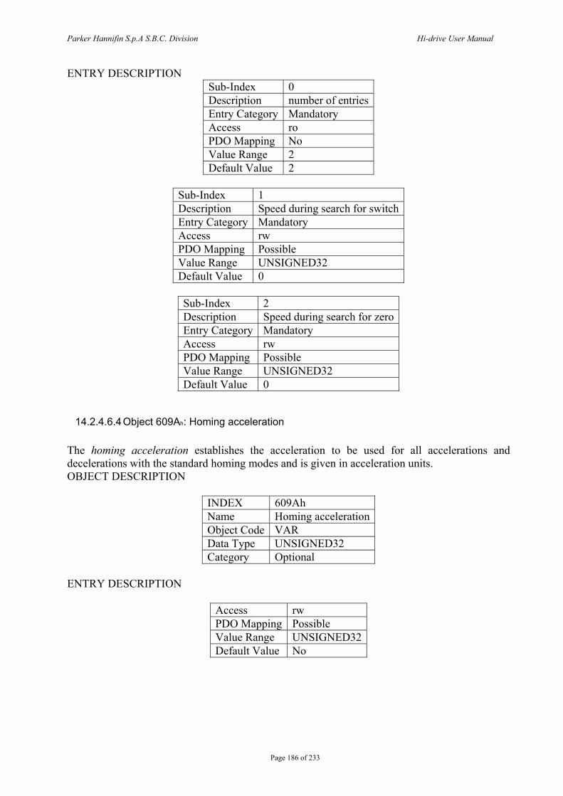
Parker Hannifin S.p.A S.B.C. Division Hi-drive User Manual
Page 186 of 233
ENTRY DESCRIPTION Sub-Index 0 Description number of entries Entry Category Mandatory Access ro PDO Mapping No Value Range 2 Default Value 2
Sub-Index 1 Description Speed during search for switch Entry Category Mandatory Access rw PDO Mapping Possible Value Range UNSIGNED32 Default Value 0
Sub-Index 2 Description Speed during search for zero Entry Category Mandatory Access rw PDO Mapping Possible Value Range UNSIGNED32 Default Value 0
14.2.4.6.4 Object 609Ah: Homing acceleration The homing acceleration establishes the acceleration to be used for all accelerations and decelerations with the standard homing modes and is given in acceleration units. OBJECT DESCRIPTION
INDEX 609Ah Name Homing acceleration Object Code VAR Data Type UNSIGNED32 Category Optional
ENTRY DESCRIPTION
Access rw PDO Mapping Possible Value Range UNSIGNED32 Default Value No
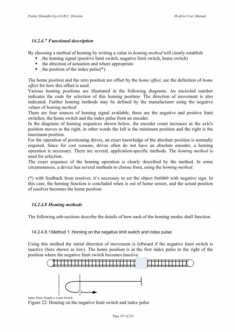
Parker Hannifin S.p.A S.B.C. Division Hi-drive User Manual
Page 187 of 233
14.2.4.7 Functional description By choosing a method of homing by writing a value to homing method will clearly establish
the homing signal (positive limit switch, negative limit switch, home switch) the direction of actuation and where appropriate the position of the index pulse(*).
The home position and the zero position are offset by the home offset, see the definition of home offset for how this offset is used. Various homing positions are illustrated in the following diagrams. An encircled number indicates the code for selection of this homing position. The direction of movement is also indicated. Further homing methods may be defined by the manufacturer using the negative values of homing method. There are four sources of homing signal available, these are the negative and positive limit switches, the home switch and the index pulse from an encoder. In the diagrams of homing sequences shown below, the encoder count increases as the axle's position moves to the right, in other words the left is the minimum position and the right is the maximum position. For the operation of positioning drives, an exact knowledge of the absolute position is normally required. Since for cost reasons, drives often do not have an absolute encoder, a homing operation is necessary. There are several, application-specific methods. The homing method is used for selection. The exact sequence of the homing operation is clearly described by the method. In some circumstances, a device has several methods to choose from, using the homing method. (*) with feedback from resolver, it’s necessary to set the object 0x6060 with negative sign. In this case, the homing function is concluded when is out of home sensor, and the actual position of resolver becomes the home position.
14.2.4.8 Homing methods The following sub-sections describe the details of how each of the homing modes shall function.
14.2.4.8.1 Method 1: Homing on the negative limit switch and index pulse Using this method the initial direction of movement is leftward if the negative limit switch is inactive (here shown as low). The home position is at the first index pulse to the right of the position where the negative limit switch becomes inactive.
(1)
Index Pulse Negative Limit Switch Figure 22: Homing on the negative limit switch and index pulse
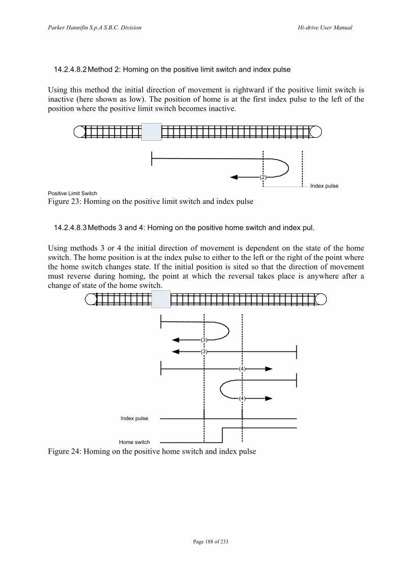
Parker Hannifin S.p.A S.B.C. Division Hi-drive User Manual
Page 188 of 233
14.2.4.8.2 Method 2: Homing on the positive limit switch and index pulse Using this method the initial direction of movement is rightward if the positive limit switch is inactive (here shown as low). The position of home is at the first index pulse to the left of the position where the positive limit switch becomes inactive.
(2)Index pulse
Positive Limit Switch Figure 23: Homing on the positive limit switch and index pulse
14.2.4.8.3 Methods 3 and 4: Homing on the positive home switch and index pul. Using methods 3 or 4 the initial direction of movement is dependent on the state of the home switch. The home position is at the index pulse to either to the left or the right of the point where the home switch changes state. If the initial position is sited so that the direction of movement must reverse during homing, the point at which the reversal takes place is anywhere after a change of state of the home switch.
(3)
Index pulse
(4)
(4)
(3)
Home switch Figure 24: Homing on the positive home switch and index pulse
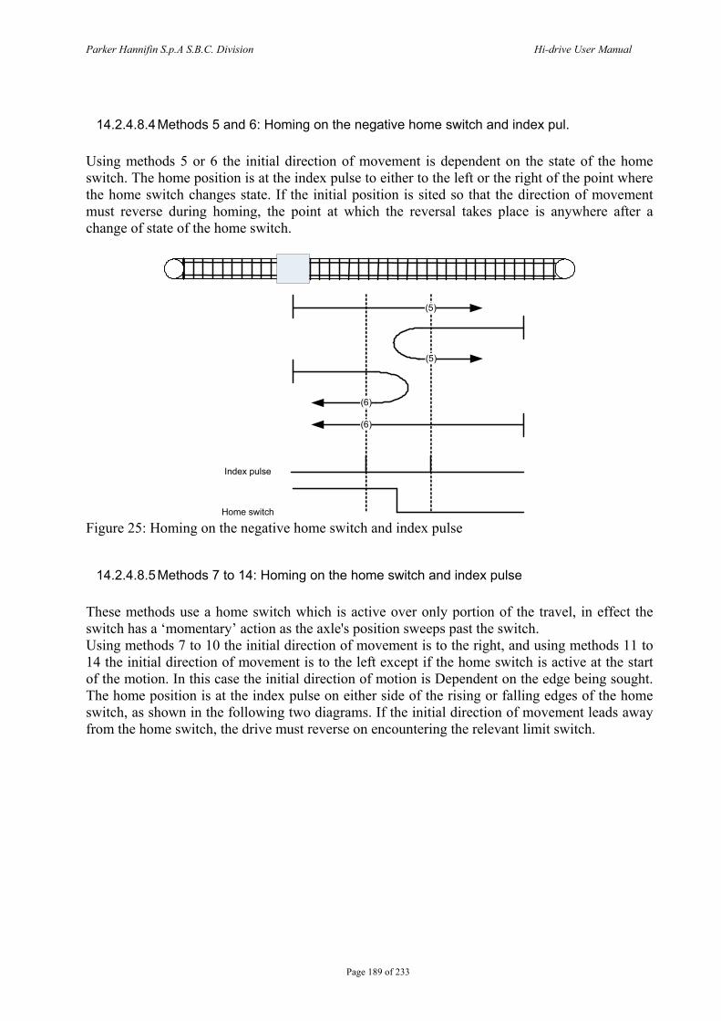
Parker Hannifin S.p.A S.B.C. Division Hi-drive User Manual
Page 189 of 233
14.2.4.8.4 Methods 5 and 6: Homing on the negative home switch and index pul. Using methods 5 or 6 the initial direction of movement is dependent on the state of the home switch. The home position is at the index pulse to either to the left or the right of the point where the home switch changes state. If the initial position is sited so that the direction of movement must reverse during homing, the point at which the reversal takes place is anywhere after a change of state of the home switch.
(6)
Index pulse
(5)
(5)
(6)
Home switch Figure 25: Homing on the negative home switch and index pulse
14.2.4.8.5 Methods 7 to 14: Homing on the home switch and index pulse These methods use a home switch which is active over only portion of the travel, in effect the switch has a ‘momentary’ action as the axle's position sweeps past the switch. Using methods 7 to 10 the initial direction of movement is to the right, and using methods 11 to 14 the initial direction of movement is to the left except if the home switch is active at the start of the motion. In this case the initial direction of motion is Dependent on the edge being sought. The home position is at the index pulse on either side of the rising or falling edges of the home switch, as shown in the following two diagrams. If the initial direction of movement leads away from the home switch, the drive must reverse on encountering the relevant limit switch.
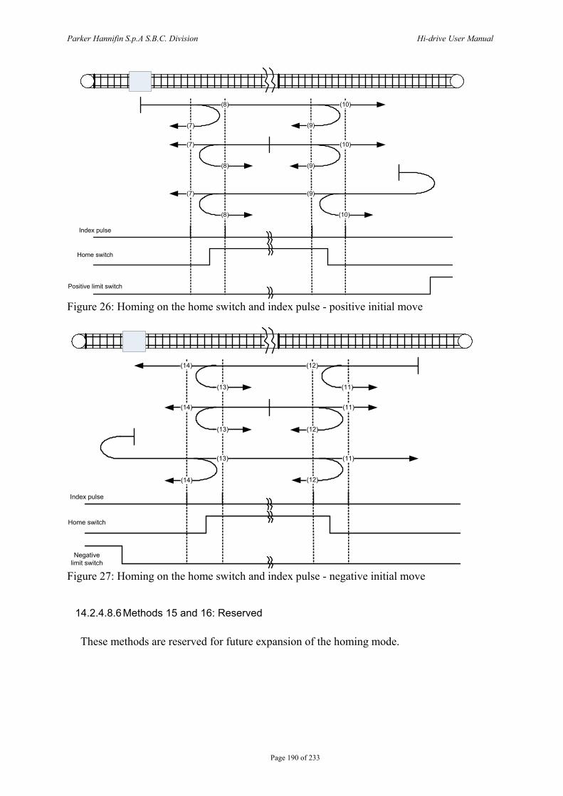
Parker Hannifin S.p.A S.B.C. Division Hi-drive User Manual
Page 190 of 233
(7)
Index pulse
Home switch
(9)
(9)
(10)
(8)
(8)
(8)
(9)
(10)
(10)
(7)
(7)
Positive limit switch
Figure 26: Homing on the home switch and index pulse - positive initial move
(14)
Index pulse
Home switch
(12)
(12)
(12)
(13)
(14)
(13)
(11)
(11)
(11)
(14)
(13)
Negative limit switch
Figure 27: Homing on the home switch and index pulse - negative initial move
14.2.4.8.6 Methods 15 and 16: Reserved
These methods are reserved for future expansion of the homing mode.
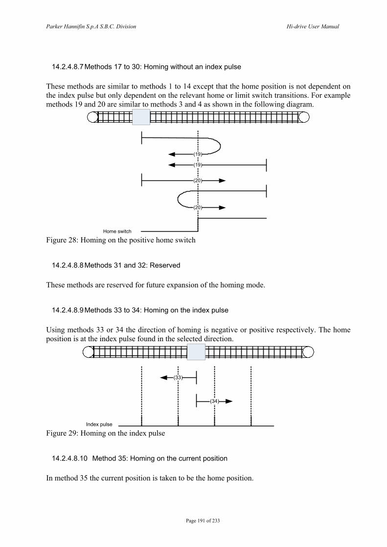
Parker Hannifin S.p.A S.B.C. Division Hi-drive User Manual
Page 191 of 233
14.2.4.8.7 Methods 17 to 30: Homing without an index pulse These methods are similar to methods 1 to 14 except that the home position is not dependent on the index pulse but only dependent on the relevant home or limit switch transitions. For example methods 19 and 20 are similar to methods 3 and 4 as shown in the following diagram.
(19)
(20)
(20)
(19)
Home switch Figure 28: Homing on the positive home switch
14.2.4.8.8 Methods 31 and 32: Reserved These methods are reserved for future expansion of the homing mode.
14.2.4.8.9 Methods 33 to 34: Homing on the index pulse Using methods 33 or 34 the direction of homing is negative or positive respectively. The home position is at the index pulse found in the selected direction.
Index pulse
(33)
(34)
Figure 29: Homing on the index pulse
14.2.4.8.10 Method 35: Homing on the current position In method 35 the current position is taken to be the home position.
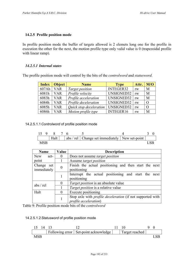
Parker Hannifin S.p.A S.B.C. Division Hi-drive User Manual
Page 192 of 233
14.2.5 Profile position mode In profile position mode the buffer of targets allowed is 2 elemets long one for the profile in execution the other for the next, the motion profile type only valid value is 0 (trapezoidal profile with linear ramp).
14.2.5.1 Internal states The profile position mode will control by the bits of the controlword and statusword.
Index Object Name Type Attr. M/O 607Ah VAR Target position INTEGER32 rw M 6081h VAR Profile velocity UNSIGNED32 rw M 6083h VAR Profile acceleration UNSIGNED32 rw M 6084h VAR Profile deceleration UNSIGNED32 rw O 6085h VAR Quick stop deceleration UNSIGNED32 rw O 6086h VAR Motion profile type INTEGER16 rw M
14.2.5.1.1 Controlword of profile position mode
15 9 8 7 6 5 4 3 0 Halt abs / rel Change set immediately New set-point MSB LSB
Name Value Description
0 Does not assume target position New set-point 1 Assume target position
0 Finish the actual positioning and then start the next positioning
Change set immediately
1 Interrupt the actual positioning and start the next positioning
0 Target position is an absolute value abs / rel 1 Target position is a relative value 0 Execute positioning Halt
1 Stop axle with profile deceleration (if not supported with profile acceleration)
Table 9: Profile position mode bits of the controlword
14.2.5.1.2 Statusword of profile position mode
15 14 13 12 11 10 9 0 Following error Set-point acknowledge Target reached MSB LSB
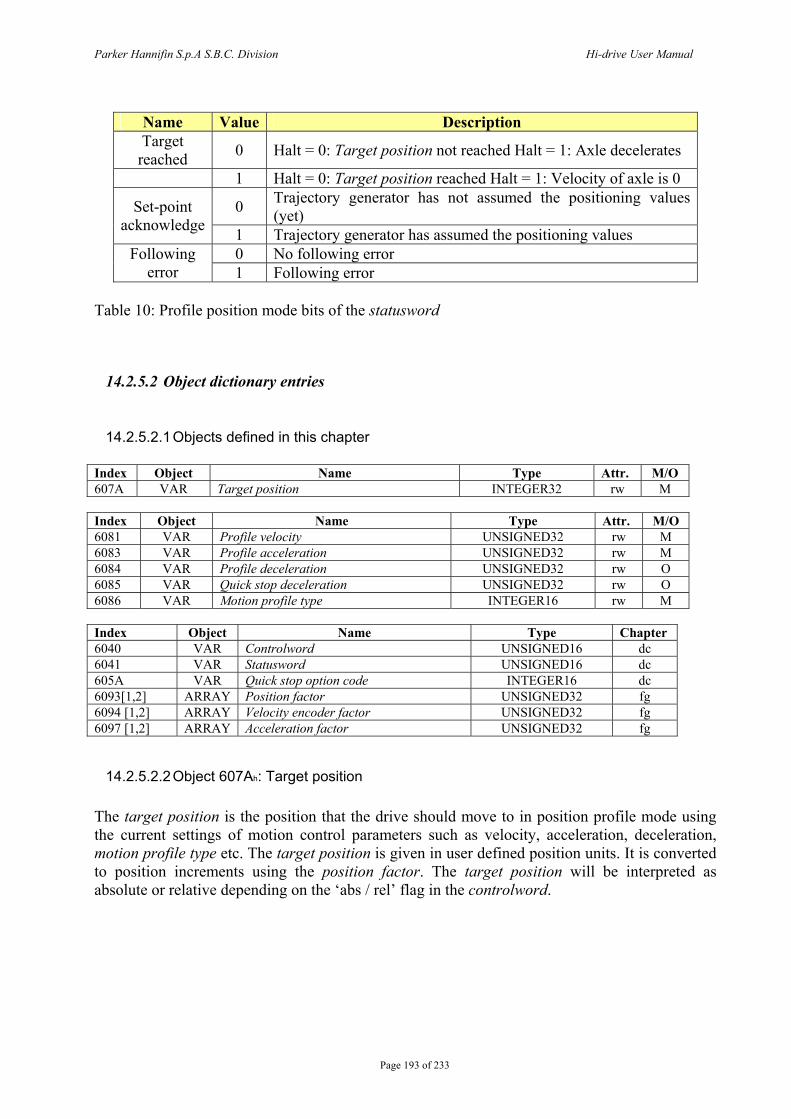
Parker Hannifin S.p.A S.B.C. Division Hi-drive User Manual
Page 193 of 233
Name Value Description Target reached 0 Halt = 0: Target position not reached Halt = 1: Axle decelerates
1 Halt = 0: Target position reached Halt = 1: Velocity of axle is 0
0 Trajectory generator has not assumed the positioning values (yet) Set-point
acknowledge 1 Trajectory generator has assumed the positioning values 0 No following error Following
error 1 Following error Table 10: Profile position mode bits of the statusword
14.2.5.2 Object dictionary entries
14.2.5.2.1 Objects defined in this chapter Index Object Name Type Attr. M/O 607A VAR Target position INTEGER32 rw M Index Object Name Type Attr. M/O 6081 VAR Profile velocity UNSIGNED32 rw M 6083 VAR Profile acceleration UNSIGNED32 rw M 6084 VAR Profile deceleration UNSIGNED32 rw O 6085 VAR Quick stop deceleration UNSIGNED32 rw O 6086 VAR Motion profile type INTEGER16 rw M Index Object Name Type Chapter 6040 VAR Controlword UNSIGNED16 dc 6041 VAR Statusword UNSIGNED16 dc 605A VAR Quick stop option code INTEGER16 dc 6093[1,2] ARRAY Position factor UNSIGNED32 fg 6094 [1,2] ARRAY Velocity encoder factor UNSIGNED32 fg 6097 [1,2] ARRAY Acceleration factor UNSIGNED32 fg
14.2.5.2.2 Object 607Ah: Target position The target position is the position that the drive should move to in position profile mode using the current settings of motion control parameters such as velocity, acceleration, deceleration, motion profile type etc. The target position is given in user defined position units. It is converted to position increments using the position factor. The target position will be interpreted as absolute or relative depending on the ‘abs / rel’ flag in the controlword.
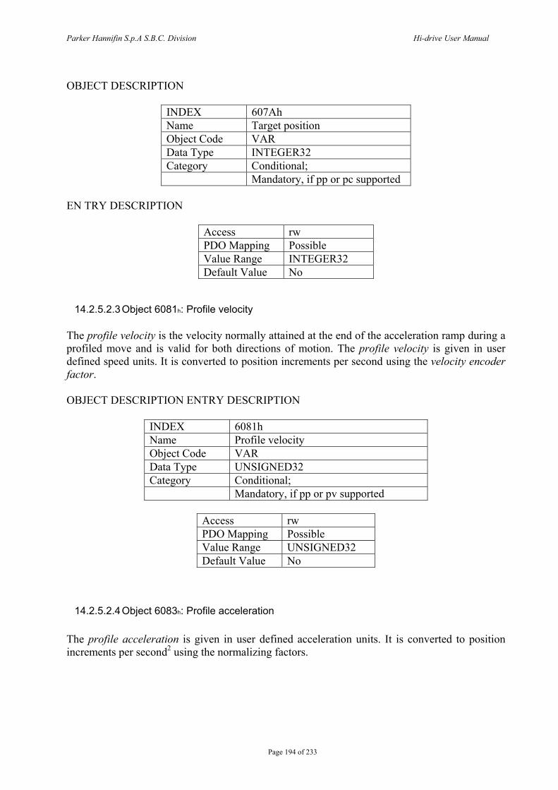
Parker Hannifin S.p.A S.B.C. Division Hi-drive User Manual
Page 194 of 233
OBJECT DESCRIPTION
INDEX 607Ah Name Target position Object Code VAR Data Type INTEGER32 Category Conditional; Mandatory, if pp or pc supported
EN TRY DESCRIPTION
Access rw PDO Mapping Possible Value Range INTEGER32 Default Value No
14.2.5.2.3 Object 6081h: Profile velocity The profile velocity is the velocity normally attained at the end of the acceleration ramp during a profiled move and is valid for both directions of motion. The profile velocity is given in user defined speed units. It is converted to position increments per second using the velocity encoder factor. OBJECT DESCRIPTION ENTRY DESCRIPTION
INDEX 6081h Name Profile velocity Object Code VAR Data Type UNSIGNED32 Category Conditional; Mandatory, if pp or pv supported
Access rw PDO Mapping Possible Value Range UNSIGNED32 Default Value No
14.2.5.2.4 Object 6083h: Profile acceleration The profile acceleration is given in user defined acceleration units. It is converted to position increments per second2 using the normalizing factors.
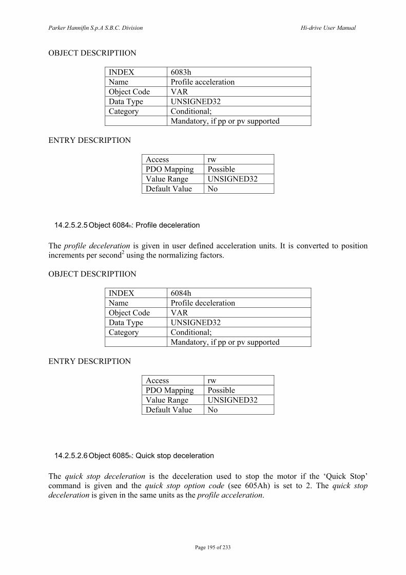
Parker Hannifin S.p.A S.B.C. Division Hi-drive User Manual
Page 195 of 233
OBJECT DESCRIPTIION
INDEX 6083h Name Profile acceleration Object Code VAR Data Type UNSIGNED32 Category Conditional; Mandatory, if pp or pv supported
ENTRY DESCRIPTION
Access rw PDO Mapping Possible Value Range UNSIGNED32 Default Value No
14.2.5.2.5 Object 6084h: Profile deceleration The profile deceleration is given in user defined acceleration units. It is converted to position increments per second2 using the normalizing factors. OBJECT DESCRIPTIION
INDEX 6084h Name Profile deceleration Object Code VAR Data Type UNSIGNED32 Category Conditional; Mandatory, if pp or pv supported
ENTRY DESCRIPTION
Access rw PDO Mapping Possible Value Range UNSIGNED32 Default Value No
14.2.5.2.6 Object 6085h: Quick stop deceleration The quick stop deceleration is the deceleration used to stop the motor if the ‘Quick Stop’ command is given and the quick stop option code (see 605Ah) is set to 2. The quick stop deceleration is given in the same units as the profile acceleration.

Parker Hannifin S.p.A S.B.C. Division Hi-drive User Manual
Page 196 of 233
OBJECT DESCRIPTION
INDEX 6085h Name Quick stop deceleration Object Code VAR Data Type UNSIGNED32 Category Optional
ENTRY DESCRIPTION
Access rw PDO Mapping Possible Value Range UNSIGNED32 Default Value No
14.2.5.2.7 Object 6086h: Motion profile type The motion profile type is used to select the type of motion profile used to perform a profiled move.
Value Description 0 Linear ramp (trapezoidal profile)
OBJECT DESCRIPTION
INDEX 6086h Name Motion profile type Object Code VAR Data Type INTEGER16 Category Conditional; Mandatory, if pp or pv supported
ENTRY DESCRIPTION
Access rw PDO Mapping Possible Value Range INTEGER16 Default Value 0
14.2.5.3 Functional description Two different ways to apply target positions to a drive, are supported by this device profile. Set of set-points: After reaching the target position the drive unit immediately processes the next target position which results in a move where the velocity of the drive normally is not reduced to zero after achieving a set-point.
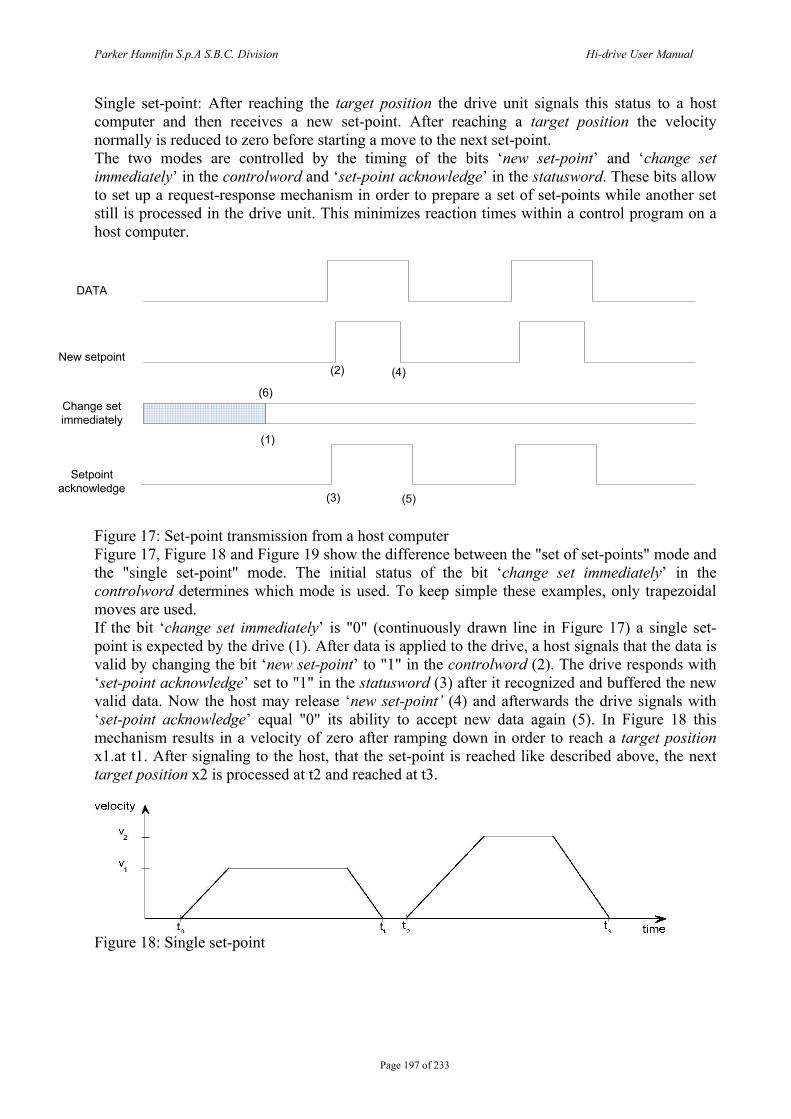
Parker Hannifin S.p.A S.B.C. Division Hi-drive User Manual
Page 197 of 233
Single set-point: After reaching the target position the drive unit signals this status to a host computer and then receives a new set-point. After reaching a target position the velocity normally is reduced to zero before starting a move to the next set-point. The two modes are controlled by the timing of the bits ‘new set-point’ and ‘change set immediately’ in the controlword and ‘set-point acknowledge’ in the statusword. These bits allow to set up a request-response mechanism in order to prepare a set of set-points while another set still is processed in the drive unit. This minimizes reaction times within a control program on a host computer.
DATA
New setpoint
Change set immediately
Setpoint acknowledge
(1)
(2)
(3)
(4)
(5)
(6)
Figure 17: Set-point transmission from a host computer Figure 17, Figure 18 and Figure 19 show the difference between the "set of set-points" mode and the "single set-point" mode. The initial status of the bit ‘change set immediately’ in the controlword determines which mode is used. To keep simple these examples, only trapezoidal moves are used. If the bit ‘change set immediately’ is "0" (continuously drawn line in Figure 17) a single set-point is expected by the drive (1). After data is applied to the drive, a host signals that the data is valid by changing the bit ‘new set-point’ to "1" in the controlword (2). The drive responds with ‘set-point acknowledge’ set to "1" in the statusword (3) after it recognized and buffered the new valid data. Now the host may release ‘new set-point’ (4) and afterwards the drive signals with ‘set-point acknowledge’ equal "0" its ability to accept new data again (5). In Figure 18 this mechanism results in a velocity of zero after ramping down in order to reach a target position x1.at t1. After signaling to the host, that the set-point is reached like described above, the next target position x2 is processed at t2 and reached at t3.
Figure 18: Single set-point
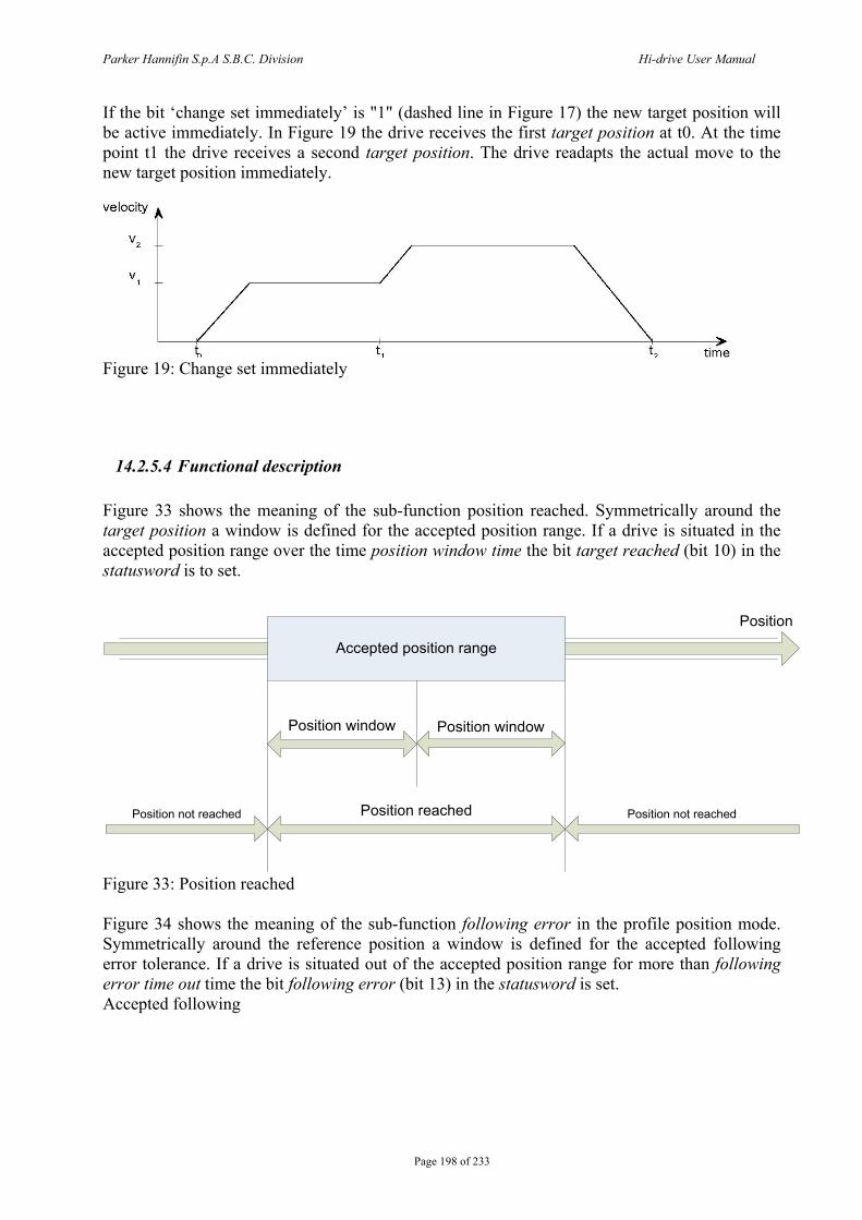
Parker Hannifin S.p.A S.B.C. Division Hi-drive User Manual
Page 198 of 233
If the bit ‘change set immediately’ is "1" (dashed line in Figure 17) the new target position will be active immediately. In Figure 19 the drive receives the first target position at t0. At the time point t1 the drive receives a second target position. The drive readapts the actual move to the new target position immediately.
Figure 19: Change set immediately
14.2.5.4 Functional description Figure 33 shows the meaning of the sub-function position reached. Symmetrically around the target position a window is defined for the accepted position range. If a drive is situated in the accepted position range over the time position window time the bit target reached (bit 10) in the statusword is to set.
Position
Accepted position range
Position window Position window
Position reachedPosition not reached Position not reached
Figure 33: Position reached Figure 34 shows the meaning of the sub-function following error in the profile position mode. Symmetrically around the reference position a window is defined for the accepted following error tolerance. If a drive is situated out of the accepted position range for more than following error time out time the bit following error (bit 13) in the statusword is set. Accepted following
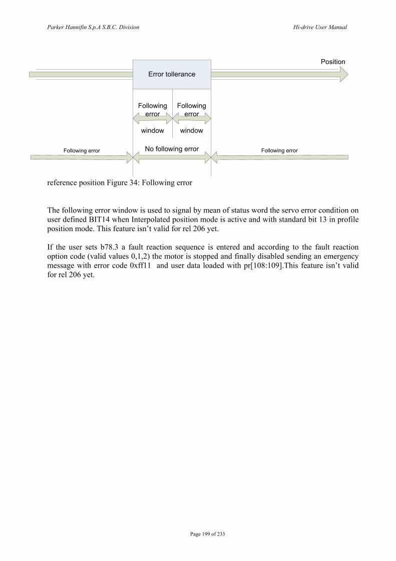
Parker Hannifin S.p.A S.B.C. Division Hi-drive User Manual
Page 199 of 233
Position
Error tollerance
Following error
window
Followingerror
window
No following errorFollowing error Following error
reference position Figure 34: Following error The following error window is used to signal by mean of status word the servo error condition on user defined BIT14 when Interpolated position mode is active and with standard bit 13 in profile position mode. This feature isn’t valid for rel 206 yet. If the user sets b78.3 a fault reaction sequence is entered and according to the fault reaction option code (valid values 0,1,2) the motor is stopped and finally disabled sending an emergency message with error code 0xff11 and user data loaded with pr[108:109].This feature isn’t valid for rel 206 yet.
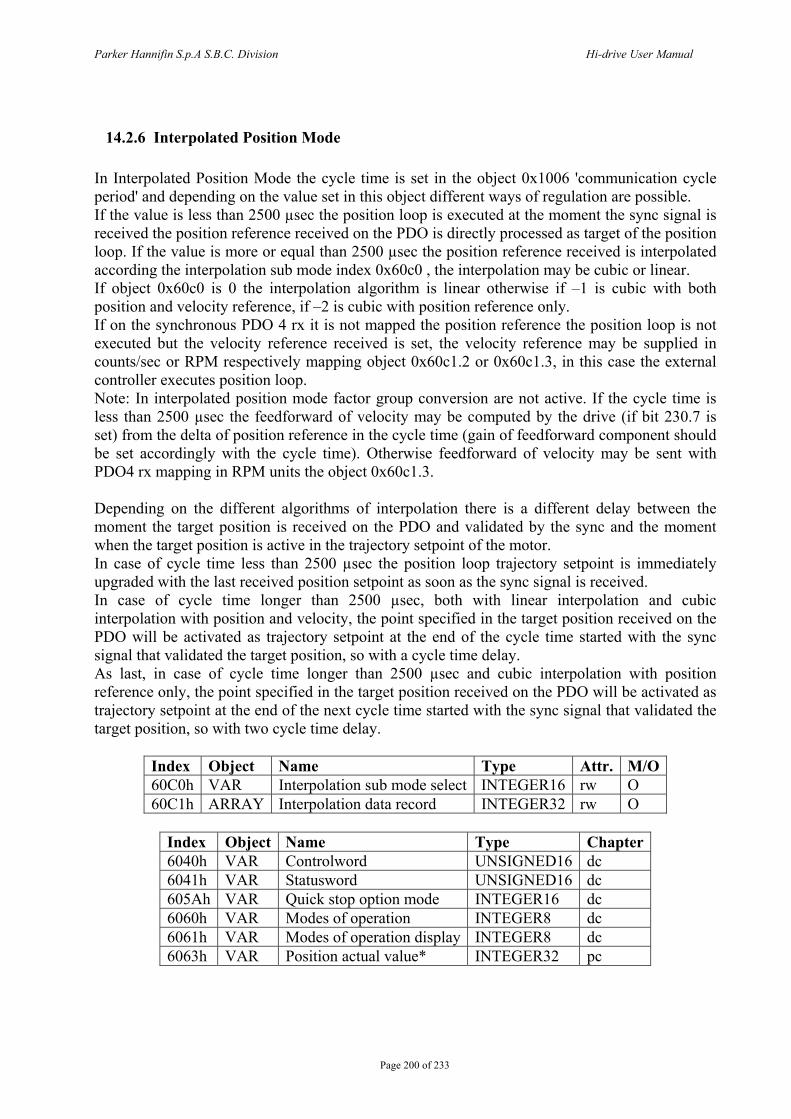
Parker Hannifin S.p.A S.B.C. Division Hi-drive User Manual
Page 200 of 233
14.2.6 Interpolated Position Mode In Interpolated Position Mode the cycle time is set in the object 0x1006 'communication cycle period' and depending on the value set in this object different ways of regulation are possible. If the value is less than 2500 µsec the position loop is executed at the moment the sync signal is received the position reference received on the PDO is directly processed as target of the position loop. If the value is more or equal than 2500 µsec the position reference received is interpolated according the interpolation sub mode index 0x60c0 , the interpolation may be cubic or linear. If object 0x60c0 is 0 the interpolation algorithm is linear otherwise if –1 is cubic with both position and velocity reference, if –2 is cubic with position reference only. If on the synchronous PDO 4 rx it is not mapped the position reference the position loop is not executed but the velocity reference received is set, the velocity reference may be supplied in counts/sec or RPM respectively mapping object 0x60c1.2 or 0x60c1.3, in this case the external controller executes position loop. Note: In interpolated position mode factor group conversion are not active. If the cycle time is less than 2500 µsec the feedforward of velocity may be computed by the drive (if bit 230.7 is set) from the delta of position reference in the cycle time (gain of feedforward component should be set accordingly with the cycle time). Otherwise feedforward of velocity may be sent with PDO4 rx mapping in RPM units the object 0x60c1.3. Depending on the different algorithms of interpolation there is a different delay between the moment the target position is received on the PDO and validated by the sync and the moment when the target position is active in the trajectory setpoint of the motor. In case of cycle time less than 2500 µsec the position loop trajectory setpoint is immediately upgraded with the last received position setpoint as soon as the sync signal is received. In case of cycle time longer than 2500 µsec, both with linear interpolation and cubic interpolation with position and velocity, the point specified in the target position received on the PDO will be activated as trajectory setpoint at the end of the cycle time started with the sync signal that validated the target position, so with a cycle time delay. As last, in case of cycle time longer than 2500 µsec and cubic interpolation with position reference only, the point specified in the target position received on the PDO will be activated as trajectory setpoint at the end of the next cycle time started with the sync signal that validated the target position, so with two cycle time delay.
Index Object Name Type Attr. M/O 60C0h VAR Interpolation sub mode select INTEGER16 rw O 60C1h ARRAY Interpolation data record INTEGER32 rw O
Index Object Name Type Chapter 6040h VAR Controlword UNSIGNED16 dc 6041h VAR Statusword UNSIGNED16 dc 605Ah VAR Quick stop option mode INTEGER16 dc 6060h VAR Modes of operation INTEGER8 dc 6061h VAR Modes of operation display INTEGER8 dc 6063h VAR Position actual value* INTEGER32 pc
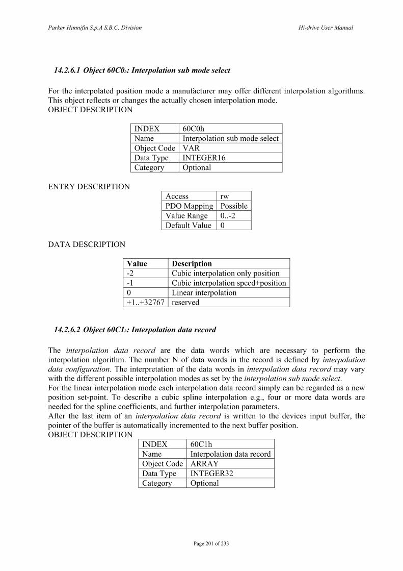
Parker Hannifin S.p.A S.B.C. Division Hi-drive User Manual
Page 201 of 233
14.2.6.1 Object 60C0h: Interpolation sub mode select For the interpolated position mode a manufacturer may offer different interpolation algorithms. This object reflects or changes the actually chosen interpolation mode. OBJECT DESCRIPTION
INDEX 60C0h Name Interpolation sub mode select Object Code VAR Data Type INTEGER16 Category Optional
ENTRY DESCRIPTION
Access rw PDO Mapping Possible Value Range 0..-2 Default Value 0
DATA DESCRIPTION
Value Description -2 Cubic interpolation only position -1 Cubic interpolation speed+position 0 Linear interpolation +1..+32767 reserved
14.2.6.2 Object 60C1h: Interpolation data record The interpolation data record are the data words which are necessary to perform the interpolation algorithm. The number N of data words in the record is defined by interpolation data configuration. The interpretation of the data words in interpolation data record may vary with the different possible interpolation modes as set by the interpolation sub mode select. For the linear interpolation mode each interpolation data record simply can be regarded as a new position set-point. To describe a cubic spline interpolation e.g., four or more data words are needed for the spline coefficients, and further interpolation parameters. After the last item of an interpolation data record is written to the devices input buffer, the pointer of the buffer is automatically incremented to the next buffer position. OBJECT DESCRIPTION
INDEX 60C1h Name Interpolation data record Object Code ARRAY Data Type INTEGER32 Category Optional

Parker Hannifin S.p.A S.B.C. Division Hi-drive User Manual
Page 202 of 233
ENTRY DESCRIPTION Sub-Index 0 Description number of entries 3Entry Category Mandatory Access ro PDO Mapping No Value Range 3 Default Value No
Sub-Index 1 Description Position setpoint in counts the first parameter of ip function fip(x1, .. xN) Entry Category Mandatory Access rw PDO Mapping Possible Value Range INTEGER32 Default Value No
Sub-Index 2 Description Velocity setpoint in counts/sec the second parameter of ip function fip(x1, .. xN) Entry Category Optional Access rw PDO Mapping Possible Value Range INTEGER32 Default Value No
Sub-Index 3 Description Velocity setpoint in rpm the 3-rd parameter of ip function fip(x1, .. xN) Entry Category Optional Access rw PDO Mapping Possible Value Range INTEGER32 Default Value No
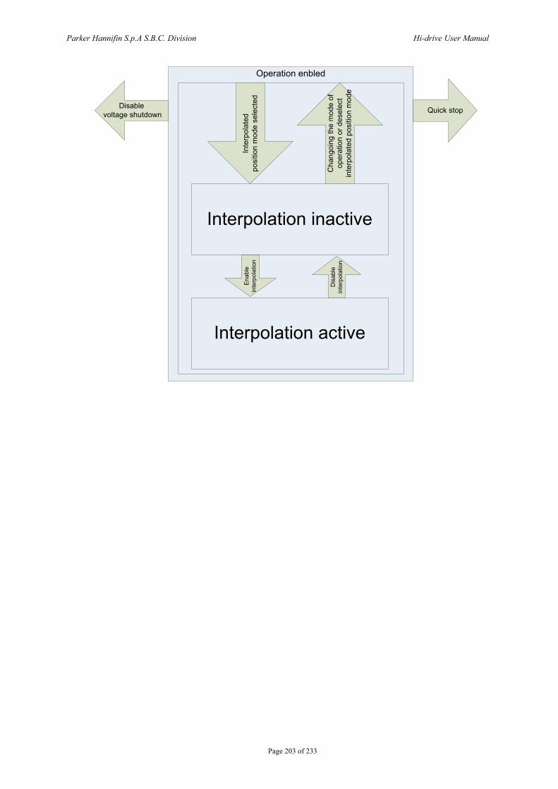
Parker Hannifin S.p.A S.B.C. Division Hi-drive User Manual
Page 203 of 233
Operation enbled
Interpolation inactive
Interpolation active
Enab
lein
terp
olat
ion
Dis
able
inte
rpol
atio
n
Inte
rpol
ated
po
sitio
n m
ode
sele
cted
Cha
ngoi
ng th
e m
ode
of
oper
atio
n or
des
elec
t in
terp
olat
ed p
ositi
on m
ode
Quick stopDisable voltage shutdown
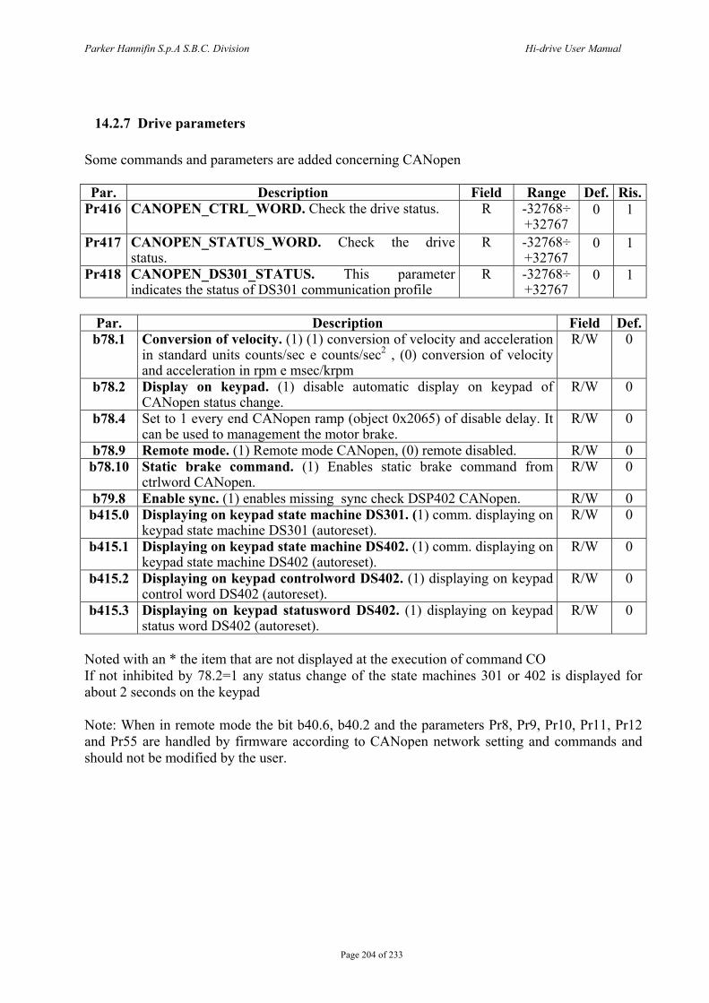
Parker Hannifin S.p.A S.B.C. Division Hi-drive User Manual
Page 204 of 233
14.2.7 Drive parameters Some commands and parameters are added concerning CANopen Par. Description Field Range Def. Ris.
Pr416 CANOPEN_CTRL_WORD. Check the drive status. R -32768÷ +32767
0 1
Pr417 CANOPEN_STATUS_WORD. Check the drive status.
R -32768÷ +32767
0 1
Pr418 CANOPEN_DS301_STATUS. This parameter indicates the status of DS301 communication profile
R -32768÷ +32767
0 1
Par. Description Field Def.b78.1 Conversion of velocity. (1) (1) conversion of velocity and acceleration
in standard units counts/sec e counts/sec2 , (0) conversion of velocity and acceleration in rpm e msec/krpm
R/W 0
b78.2 Display on keypad. (1) disable automatic display on keypad of CANopen status change.
R/W 0
b78.4 Set to 1 every end CANopen ramp (object 0x2065) of disable delay. It can be used to management the motor brake.
R/W 0
b78.9 Remote mode. (1) Remote mode CANopen, (0) remote disabled. R/W 0 b78.10 Static brake command. (1) Enables static brake command from
ctrlword CANopen. R/W 0
b79.8 Enable sync. (1) enables missing sync check DSP402 CANopen. R/W 0 b415.0 Displaying on keypad state machine DS301. (1) comm. displaying on
keypad state machine DS301 (autoreset). R/W 0
b415.1 Displaying on keypad state machine DS402. (1) comm. displaying on keypad state machine DS402 (autoreset).
R/W 0
b415.2 Displaying on keypad controlword DS402. (1) displaying on keypad control word DS402 (autoreset).
R/W 0
b415.3 Displaying on keypad statusword DS402. (1) displaying on keypad status word DS402 (autoreset).
R/W 0
Noted with an * the item that are not displayed at the execution of command CO If not inhibited by 78.2=1 any status change of the state machines 301 or 402 is displayed for about 2 seconds on the keypad Note: When in remote mode the bit b40.6, b40.2 and the parameters Pr8, Pr9, Pr10, Pr11, Pr12 and Pr55 are handled by firmware according to CANopen network setting and commands and should not be modified by the user.

Parker Hannifin S.p.A S.B.C. Division Hi-drive User Manual
Page 205 of 233
14.2.8 CANopen monitor by ASCII commands The ASCII protocol o rs232 support an additional command to display CANopen settings, typing CE or CO command the CANopen setting page is shown. CE ------------------------------- CANopen Info page ----------------------------- ............................................................................... Baud rate : 1 Mbps Node Address: 001 Communication status : Pre-Operational bus off: NO bus warning: NO State Machine: Fault Mode of operation: Interpolated Position ............................................................................... Control word: 0 0x0000 0000000000000000 bit0 : Switch On 0 bit1 : Enable voltage 0 bit2 : Quick Stop 0 bit3 : Enable operation 0 bit4 : Operation mode specific 0 bit5 : Operation mode specific 0 bit6 : Operation mode specific 0 bit7 : Fault Reset 0 bit8 : Halt 0 bit9 : Reserved 0 bit10 : Reserved 0 bit11 : Manufacturer specific 0 bit12 : Manufacturer specific 0 bit13 : Manufacturer specific 0 bit14 : Manufacturer specific 0 bit15 : Manufacturer specific 0 ............................................................................... Status word: 8712 0x2208 0010001000001000 bit0 : Ready to Switch On 0 bit1 : Switched On 0 bit2 : Operation enabled 0 bit3 : Fault 1 bit4 : Voltage enabled 0 bit5 : Quick stop 0 bit6 : Switch on disabled 0 bit7 : Warning 0 bit8 : Manufacturer specific 0 bit9 : Remote 1 bit10 : Target Reached 0 bit11 : Internal limit active 0 bit12 : Operation mode specific 0 bit13 : Operation mode specific 1 bit14 : Manufacturer specific 0 bit15 : Manufacturer specific 0
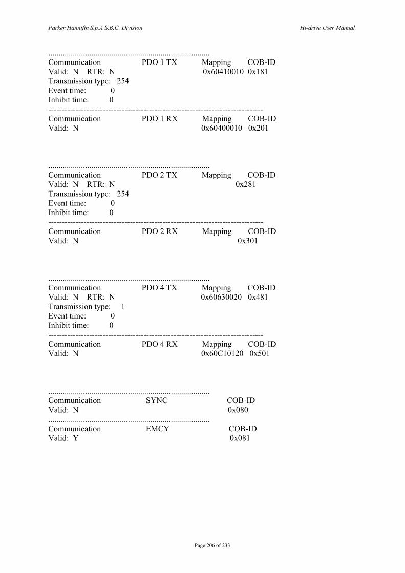
Parker Hannifin S.p.A S.B.C. Division Hi-drive User Manual
Page 206 of 233
............................................................................... Communication PDO 1 TX Mapping COB-ID Valid: N RTR: N 0x60410010 0x181 Transmission type: 254 Event time: 0 Inhibit time: 0 ------------------------------------------------------------------------------- Communication PDO 1 RX Mapping COB-ID Valid: N 0x60400010 0x201 ............................................................................... Communication PDO 2 TX Mapping COB-ID Valid: N RTR: N 0x281 Transmission type: 254 Event time: 0 Inhibit time: 0 ------------------------------------------------------------------------------- Communication PDO 2 RX Mapping COB-ID Valid: N 0x301 ............................................................................... Communication PDO 4 TX Mapping COB-ID Valid: N RTR: N 0x60630020 0x481 Transmission type: 1 Event time: 0 Inhibit time: 0 ------------------------------------------------------------------------------- Communication PDO 4 RX Mapping COB-ID Valid: N 0x60C10120 0x501 ............................................................................... Communication SYNC COB-ID Valid: N 0x080 ............................................................................... Communication EMCY COB-ID Valid: Y 0x081

Parker Hannifin S.p.A S.B.C. Division Hi-drive User Manual
Page 207 of 233
15 PROGRAMMING THE CONVERTER THROUGH A PC
A serial kit (USBTODRIVE) is available to communicate with the converter through a personal computer. The kit includes a RS-422/RS-232 converter and serial link cable. The installation requirements for the freely supplied communication software MotionWiz are a personal computer (PII or higher recommended) running on Windows* 98 or later, a mouse to navigate within the program and a serial link to the converter. The main features of Motion Wiz are:
- serial connection to up to 32 converters reading and setting key parameters and converter commands
- reading and setting operating mode parameters and commands - functional block diagrams - Pico-PLC programming in text and ladder format - display of Pico-PLC program during operation - status of inputs and outputs - parameter setting storage, including Pico-PLC program in one file - parameter setting loading, including Pico-PLC program from one of the
previously stored files (selectable) - oscilloscope function
*Windows and the Windows logo are registered marks or trademarks of Microsoft Corporation in the United States and/or in other countries.
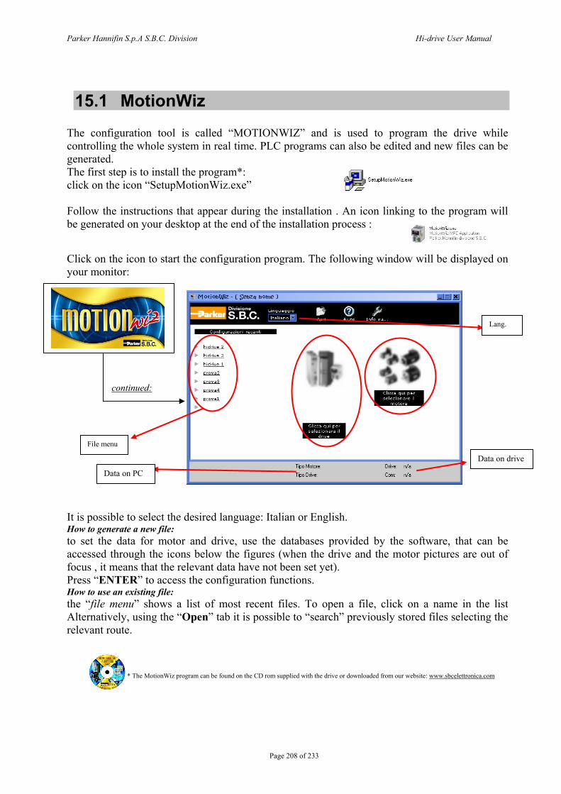
Parker Hannifin S.p.A S.B.C. Division Hi-drive User Manual
Page 208 of 233
15.1 MotionWiz The configuration tool is called “MOTIONWIZ” and is used to program the drive while controlling the whole system in real time. PLC programs can also be edited and new files can be generated. The first step is to install the program*: click on the icon “SetupMotionWiz.exe” Follow the instructions that appear during the installation . An icon linking to the program will be generated on your desktop at the end of the installation process : Click on the icon to start the configuration program. The following window will be displayed on your monitor:
continued:
It is possible to select the desired language: Italian or English. How to generate a new file: to set the data for motor and drive, use the databases provided by the software, that can be accessed through the icons below the figures (when the drive and the motor pictures are out of focus , it means that the relevant data have not been set yet). Press “ENTER” to access the configuration functions. How to use an existing file: the “file menu” shows a list of most recent files. To open a file, click on a name in the list Alternatively, using the “Open” tab it is possible to “search” previously stored files selecting the relevant route.
* The MotionWiz program can be found on the CD rom supplied with the drive or downloaded from our website: www.sbcelettronica.com
File menu
Lang.
Data on PC
Data on drive
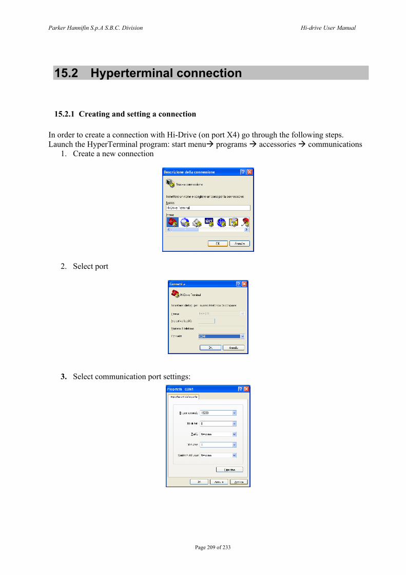
Parker Hannifin S.p.A S.B.C. Division Hi-drive User Manual
Page 209 of 233
15.2 Hyperterminal connection
15.2.1 Creating and setting a connection In order to create a connection with Hi-Drive (on port X4) go through the following steps. Launch the HyperTerminal program: start menu programs accessories communications
1. Create a new connection
2. Select port
3. Select communication port settings:
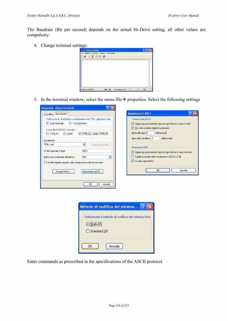
Parker Hannifin S.p.A S.B.C. Division Hi-drive User Manual
Page 210 of 233
The Baudrate (Bit per second) depends on the actual Hi-Drive setting, all other values are compulsory.
4. Change terminal settings:
5. In the terminal window, select the menu file properties. Select the following settings
Enter commands as prescribed in the specifications of the ASCII protocol.

Parker Hannifin S.p.A S.B.C. Division Hi-drive User Manual
Page 211 of 233
15.2.2 ASCII protocol port RS-232
This is the protocol used on port TS232 of the drive. This is used for a point-to-point communication. Therefore, only one driver can be connected to this interface, and it is not necessary to enter the drive’s address. The messages used in communication are reported in the table below, where the message fields feature a “#”followed by a letter.
Range Field Description Max Min #a Parameter number NUM_PAR-1 0 #b Bit number 15 0 #c Pico-PLC instruction number 255 0 #d Table number N_TABLES-1 0 #e Point of the table number END_ADR - START_ADR 0
#g Word (16 bit) value (signed) (unsigned)
32767 65535
-32767 0
#h Long (32 bit) value (signed) +232-1 -232 #i Bit status value 1 0
[m] Pico-PLC instruction mnemonic code (2, 3 or 4 characters) See the paragraph on Pico-PLC
#n 16 character Text Message string text #1 Pico-PLC 1st operand See the paragraph on Pico-PLC #2 Pico-PLC 2nd operand See the paragraph on Pico-PLC #3 Pico-PLC 3rd operand See the paragraph on Pico-PLC #n 16-char message string
NUM_PAR and N_TABLES, and START_ADR, END_ADR for each table can be read directly in the drive through dedicated commands.
HI-Drive ASCII protocol: messages definition Write Commands
Description Tx Format Word parameter value P#a=#g<CR> Long parameter value PL#a=#h<CR> Bit status B#a.#b=#i<CR> overwrite Pico-PLC instruction (#) I#c=#m#1.#2.#3<CR> d word point value TABLE T#d.#e<CR> d long point value TABLE TL#d.#e<CR>
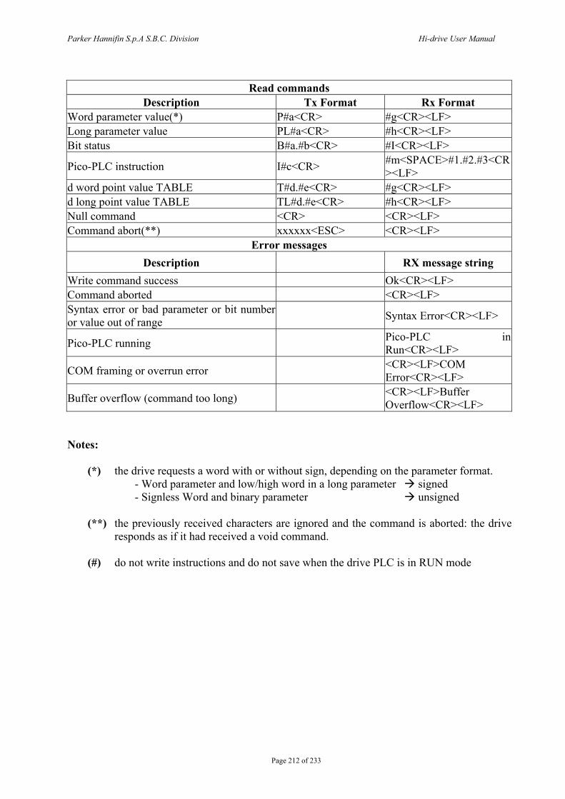
Parker Hannifin S.p.A S.B.C. Division Hi-drive User Manual
Page 212 of 233
Read commands
Description Tx Format Rx Format Word parameter value(*) P#a<CR> #g<CR><LF> Long parameter value PL#a<CR> #h<CR><LF> Bit status B#a.#b<CR> #I<CR><LF>
Pico-PLC instruction I#c<CR> #m<SPACE>#1.#2.#3<CR><LF>
d word point value TABLE T#d.#e<CR> #g<CR><LF> d long point value TABLE TL#d.#e<CR> #h<CR><LF> Null command <CR> <CR><LF> Command abort(**) xxxxxx<ESC> <CR><LF>
Error messages Description RX message string
Write command success Ok<CR><LF> Command aborted <CR><LF> Syntax error or bad parameter or bit number or value out of range Syntax Error<CR><LF>
Pico-PLC running Pico-PLC in Run<CR><LF>
COM framing or overrun error <CR><LF>COM Error<CR><LF>
Buffer overflow (command too long) <CR><LF>Buffer Overflow<CR><LF>
Notes:
(*) the drive requests a word with or without sign, depending on the parameter format. - Word parameter and low/high word in a long parameter signed - Signless Word and binary parameter unsigned (**) the previously received characters are ignored and the command is aborted: the drive
responds as if it had received a void command. (#) do not write instructions and do not save when the drive PLC is in RUN mode
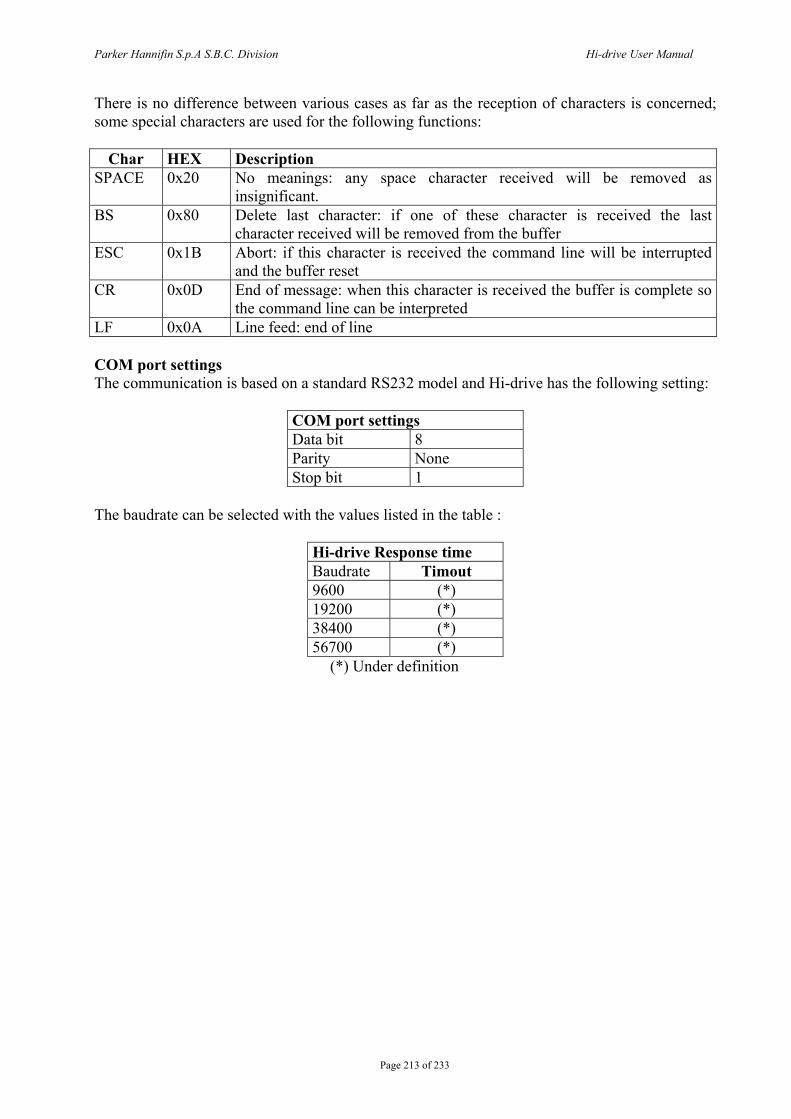
Parker Hannifin S.p.A S.B.C. Division Hi-drive User Manual
Page 213 of 233
There is no difference between various cases as far as the reception of characters is concerned; some special characters are used for the following functions:
Char HEX Description SPACE 0x20 No meanings: any space character received will be removed as
insignificant. BS 0x80 Delete last character: if one of these character is received the last
character received will be removed from the buffer ESC 0x1B Abort: if this character is received the command line will be interrupted
and the buffer reset CR 0x0D End of message: when this character is received the buffer is complete so
the command line can be interpreted LF 0x0A Line feed: end of line COM port settings The communication is based on a standard RS232 model and Hi-drive has the following setting:
COM port settings Data bit 8 Parity None Stop bit 1
The baudrate can be selected with the values listed in the table :
Hi-drive Response time Baudrate Timout 9600 (*) 19200 (*) 38400 (*) 56700 (*)
(*) Under definition
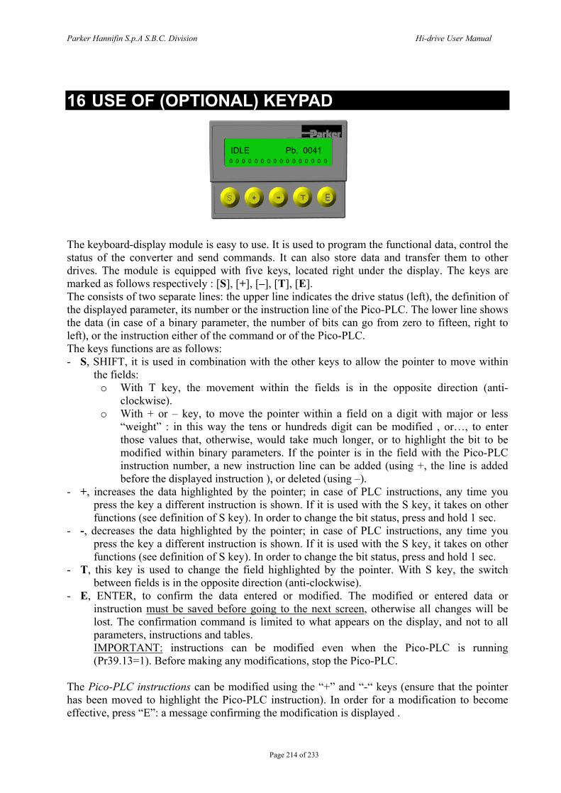
Parker Hannifin S.p.A S.B.C. Division Hi-drive User Manual
Page 214 of 233
16 USE OF (OPTIONAL) KEYPAD The keyboard-display module is easy to use. It is used to program the functional data, control the status of the converter and send commands. It can also store data and transfer them to other drives. The module is equipped with five keys, located right under the display. The keys are marked as follows respectively : [S], [+], [–], [T], [E]. The consists of two separate lines: the upper line indicates the drive status (left), the definition of the displayed parameter, its number or the instruction line of the Pico-PLC. The lower line shows the data (in case of a binary parameter, the number of bits can go from zero to fifteen, right to left), or the instruction either of the command or of the Pico-PLC. The keys functions are as follows: - S, SHIFT, it is used in combination with the other keys to allow the pointer to move within
the fields: o With T key, the movement within the fields is in the opposite direction (anti-
clockwise). o With + or – key, to move the pointer within a field on a digit with major or less
“weight” : in this way the tens or hundreds digit can be modified , or…, to enter those values that, otherwise, would take much longer, or to highlight the bit to be modified within binary parameters. If the pointer is in the field with the Pico-PLC instruction number, a new instruction line can be added (using +, the line is added before the displayed instruction ), or deleted (using –).
- +, increases the data highlighted by the pointer; in case of PLC instructions, any time you press the key a different instruction is shown. If it is used with the S key, it takes on other functions (see definition of S key). In order to change the bit status, press and hold 1 sec.
- -, decreases the data highlighted by the pointer; in case of PLC instructions, any time you press the key a different instruction is shown. If it is used with the S key, it takes on other functions (see definition of S key). In order to change the bit status, press and hold 1 sec.
- T, this key is used to change the field highlighted by the pointer. With S key, the switch between fields is in the opposite direction (anti-clockwise).
- E, ENTER, to confirm the data entered or modified. The modified or entered data or instruction must be saved before going to the next screen, otherwise all changes will be lost. The confirmation command is limited to what appears on the display, and not to all parameters, instructions and tables. IMPORTANT: instructions can be modified even when the Pico-PLC is running (Pr39.13=1). Before making any modifications, stop the Pico-PLC.
The Pico-PLC instructions can be modified using the “+” and “-“ keys (ensure that the pointer has been moved to highlight the Pico-PLC instruction). In order for a modification to become effective, press “E”: a message confirming the modification is displayed .
0 0 0 0 0 0 0 0 0 0 0 0 0 0 0 0
IDLE Pb. 0041

Parker Hannifin S.p.A S.B.C. Division Hi-drive User Manual
Page 215 of 233
The Pico-PLC instructions data can be modified using the “+” and “-“ keys (ensure that the pointer has been moved to highlight the Pico-PLC instruction). In order for a modification to become effective, press “E”: a message confirming the modification is displayed . The value of decimal parameters and the parameter data in the tables can be modified using the “+” and “-“ keys (ensure that the pointer has been moved to highlight the value of the decimal parameter or the parameter value in the tables ). The bit status in binary parameters can be modified using the “+” and “-“ keys (ensure that the pointer has been moved to highlight the bit to be modified). The bits are numbered from 0 to 15 and are shown in growing order, right to left. In order to move the pointer between bits, left to right, press the “S” and “+” keys simultaneously; to move the pointer between bits, right to left, press the “S” and “-”keys simultaneously). - The data format to be entered in the parameter is already set. If the data is not accepted it
means that its format does not match the required format. - All double word parameters are displayed entirely, not limited to either the high word or the
low word. This makes it easier to understand the “long” parameter. - The keypad can update and store all the parameter values in a 2Kbyte memory. Another
2Kbyte memory is dedicated to CAM tables. This system makes it easy to transfer the stored data to other Hi-drive units.
- Error messages are also displayed on the screen. - Whenever entering a Pico-PLC instruction, in order for the entered instruction to be saved,
press the Enter key. Otherwise, the previous instructions will remain effective. - A confirmation message will be displayed: changing, inserting, deleting. The parameter definition can be identified by the following markings: Pr (parameter), Pb (binary parameter), In (Pico-PLC instruction), Cmd (commands), T (tables): Pr. xx Indicates parameter xx for 16 bit word. PL. xx Indicates parameter xx for 32 bit word, marked as long parameters. Pb. xx Indicates the binary parameter at 16 bit xx. In. xx Indicates the xx instruction number of the Pico-PLC program. Ty. xx Parameter table, y indicates the table number, xx is the parameter number. Cmd send keypad command. The type of command is displayed on the second line. Here follows a list of possible commands (the pointer must be positioned in the second line. Other commands can be seen using the + key):
Upload and download of parameters and tables. The data are stored in the Eeprom. Upload and download of Pico-PLC instructions. The data are stored in the Eeprom. Reduction or enlargement of the display menu. The enlarged menu can display all
parameters (in order to see all parameters, press the Enter key to activate this function). Each command must be performed from the command Enter. Through these commands the settings can be transferred between drives. Ensure that the drive and motor versions where the parameters will be applied have been correctly identified: ensure that drive and motor have the same features. The following messages may be displayed on the screen, in addition to the value of the parameters and the instructions of the Pico-PLC: IdLE At start up. It indicates that the converter is disabled. run At start up and by Pr0, this message indicates that there is no alarm and that the
converter is enabled. The motor shaft may be rotating. Er. xx This message indicates that the converter has detected an alarm (xx indicates the alarm
code) and has therefore been disabled. When it detects an alarm, the converter is brought to Pr0 and the alarm code is displayed.
dEF Indicates that the drive is set to default status and must be programmed using the motor key parameters. Error code = 15.
It is possible to select what parameter you want to be displayed when the drive is powered on. Follow the procedure below: connect the keypad to the drive to power it up; move to the
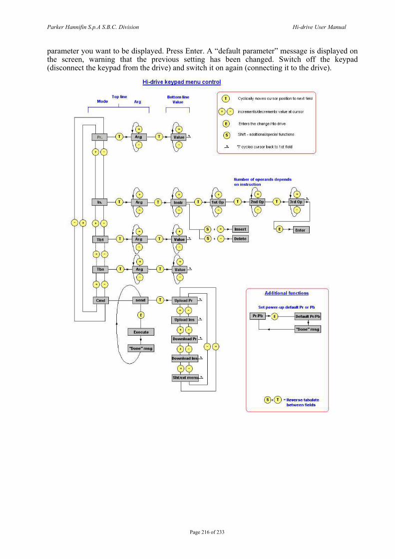
Parker Hannifin S.p.A S.B.C. Division Hi-drive User Manual
Page 216 of 233
parameter you want to be displayed. Press Enter. A “default parameter” message is displayed on the screen, warning that the previous setting has been changed. Switch off the keypad (disconnect the keypad from the drive) and switch it on again (connecting it to the drive).
Tot> line Mode Al'g
Hi-drive keypad menu control
Bottom line 0 Cyclically moves cu·sor posnion to next field Value
GO increments/decrements value &t cursor
~ ® ® ..!I.
Enters the change hto drive
Shift • adddional/special functions
'T' cycles cursor back to 1st field
Uum bor of opernn(l & d OIJOn ds on inst•·uction
Additional functions
Set 11o w et · liJ) default Pr 01 Pb
@)+(D =Reverse tab ulate between fields

Parker Hannifin S.p.A S.B.C. Division Hi-drive User Manual
Page 217 of 233
17 Appendix A : Conventions
Reference Positive Motor shaft movement(motor shaft view) Torque Positive Resolver counter Increments
A Encoder output B Tachometer signal Positive Iu ( )ϑsin•torque
Iv ⎟⎠⎞
⎜⎝⎛ •
+•3
2sin πϑtorque
Encoder In. A B
Counter increment
Frequency A
Direction B Counter increment
18 Appendix B : Flash information • TO SAVE PARAMETERS USE b42.15 • TO SAVE THE PLC PROGRAM USE b42.14 • TO CHANGE THE INSTRUCTIONS, PLC b39.13 MUST BE 0 • WHEN THE OPERATING MODE IS CHANGED, USE b42.13 TO LOAD THE DEFAULT
PARAMETERS (b40.2 MUST BE 0) • BEOFRE CHANGING Pr181, MAKE SURE THAT b40.2=0 • THE SPEED REFERENCE WILL BE LIMITED TO THE VALUE OF Pr32 • WHEN TORQUE CONTROL IS USED, Pr2 AND Pr3 MUST BE SET TO 1000 • WHEN AN ACTIVE OPERATING MODE IS USED, b40.2 MUST BE 1 • IF READ-WRITE PARAMETERS CANNOT BE CHANGED USING THE KEYPAD,
MAKE SURE THAT b42.1 IS 1. IF IT WAS 1, PROBABLY THE SAME PARAMETERS ARE MODIFIED BY THE PLC PROGRAM.
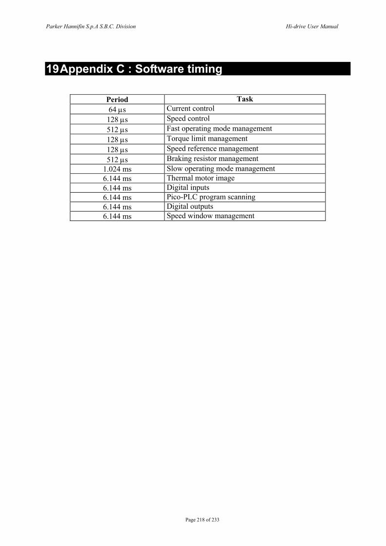
Parker Hannifin S.p.A S.B.C. Division Hi-drive User Manual
Page 218 of 233
19 Appendix C : Software timing
Period Task 64 μs Current control 128 μs Speed control 512 μs Fast operating mode management 128 μs Torque limit management 128 μs Speed reference management 512 μs Braking resistor management
1.024 ms Slow operating mode management 6.144 ms Thermal motor image 6.144 ms Digital inputs 6.144 ms Pico-PLC program scanning 6.144 ms Digital outputs 6.144 ms Speed window management
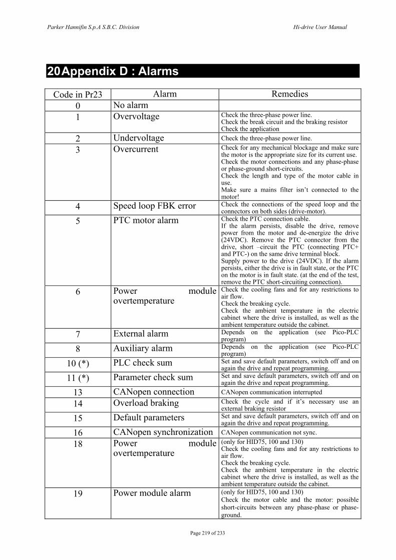
Parker Hannifin S.p.A S.B.C. Division Hi-drive User Manual
Page 219 of 233
20 Appendix D : Alarms
Code in Pr23 Alarm Remedies 0 No alarm 1 Overvoltage Check the three-phase power line.
Check the break circuit and the braking resistor Check the application
2 Undervoltage Check the three-phase power line. 3 Overcurrent Check for any mechanical blockage and make sure
the motor is the appropriate size for its current use. Check the motor connections and any phase-phase or phase-ground short-circuits. Check the length and type of the motor cable in use. Make sure a mains filter isn’t connected to the motor!
4 Speed loop FBK error Check the connections of the speed loop and the connectors on both sides (drive-motor).
5 PTC motor alarm Check the PTC connection cable. If the alarm persists, disable the drive, remove power from the motor and de-energize the drive (24VDC). Remove the PTC connector from the drive, short –circuit the PTC (connecting PTC+ and PTC-) on the same drive terminal block. Supply power to the drive (24VDC). If the alarm persists, either the drive is in fault state, or the PTC on the motor is in fault state. (at the end of the test, remove the PTC short-circuiting connection).
6 Power module overtemperature
Check the cooling fans and for any restrictions to air flow. Check the breaking cycle. Check the ambient temperature in the electric cabinet where the drive is installed, as well as the ambient temperature outside the cabinet.
7 External alarm Depends on the application (see Pico-PLC program)
8 Auxiliary alarm Depends on the application (see Pico-PLC program)
10 (*) PLC check sum Set and save default parameters, switch off and on again the drive and repeat programming.
11 (*) Parameter check sum Set and save default parameters, switch off and on again the drive and repeat programming.
13 CANopen connection CANopen communication interrupted
14 Overload braking Check the cycle and if it’s necessary use an external braking resistor
15 Default parameters Set and save default parameters, switch off and on again the drive and repeat programming.
16 CANopen synchronization CANopen communication not sync.
18 Power module overtemperature
(only for HID75, 100 and 130) Check the cooling fans and for any restrictions to air flow. Check the breaking cycle. Check the ambient temperature in the electric cabinet where the drive is installed, as well as the ambient temperature outside the cabinet.
19 Power module alarm (only for HID75, 100 and 130) Check the motor cable and the motor: possible short-circuits between any phase-phase or phase-ground.
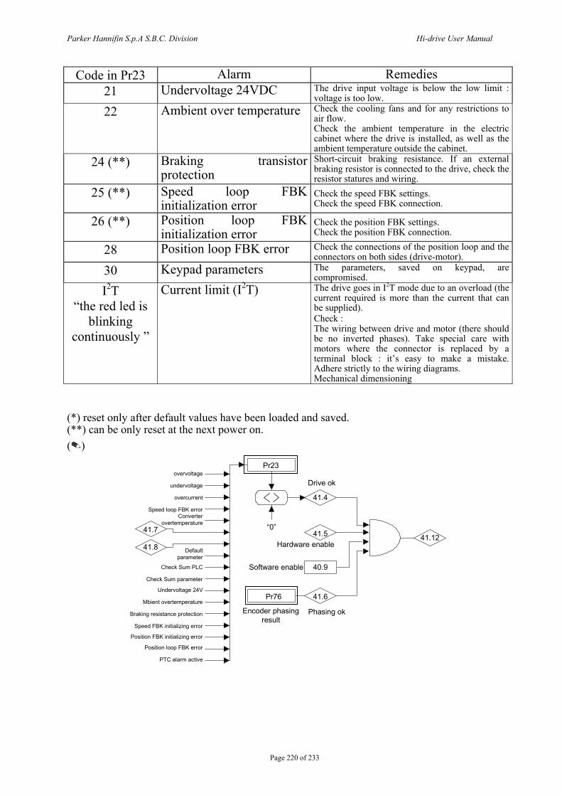
Parker Hannifin S.p.A S.B.C. Division Hi-drive User Manual
Page 220 of 233
Code in Pr23 Alarm Remedies 21 Undervoltage 24VDC The drive input voltage is below the low limit :
voltage is too low. 22 Ambient over temperature Check the cooling fans and for any restrictions to
air flow. Check the ambient temperature in the electric cabinet where the drive is installed, as well as the ambient temperature outside the cabinet.
24 (**) Braking transistor protection
Short-circuit braking resistance. If an external braking resistor is connected to the drive, check the resistor statures and wiring.
25 (**) Speed loop FBK initialization error
Check the speed FBK settings. Check the speed FBK connection.
26 (**) Position loop FBK initialization error
Check the position FBK settings. Check the position FBK connection.
28 Position loop FBK error Check the connections of the position loop and the connectors on both sides (drive-motor).
30 Keypad parameters The parameters, saved on keypad, are compromised.
I2T “the red led is
blinking continuously ”
Current limit (I2T) The drive goes in I2T mode due to an overload (the current required is more than the current that can be supplied). Check : The wiring between drive and motor (there should be no inverted phases). Take special care with motors where the connector is replaced by a terminal block : it’s easy to make a mistake. Adhere strictly to the wiring diagrams. Mechanical dimensioning
(*) reset only after default values have been loaded and saved. (**) can be only reset at the next power on. ()
Pr23
41.4
41.541.7
41.8
40.9
Pr76 41.6
41.12“0”
Software enable
Hardware enable
Encoder phasingresult
Phasing ok
Drive okovervoltage
undervoltage
PTC alarm active
overcurrent
Speed loop FBK errorConverter
overtemperature
Default parameter
Check Sum parameter
Undervoltage 24V
Mbient overtemperature
Braking resistance protection
Speed FBK initializing error
Position FBK initializing error
Position loop FBK error
Check Sum PLC
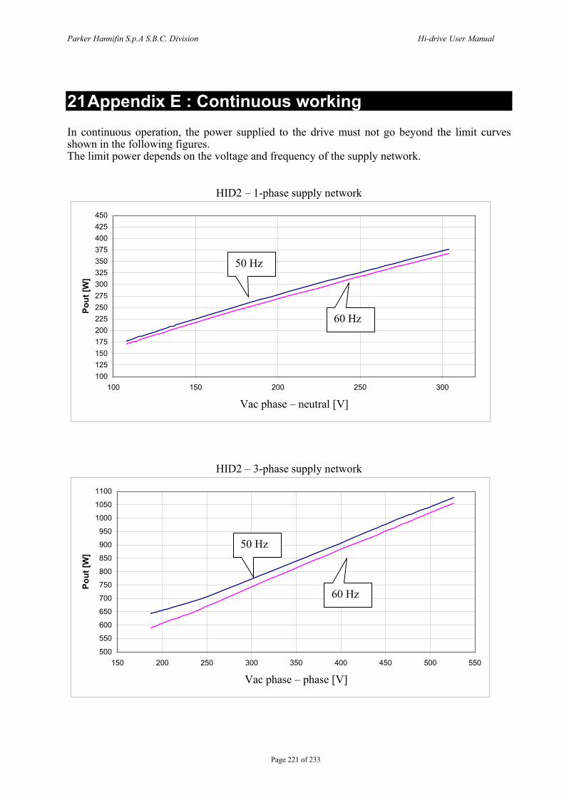
Parker Hannifin S.p.A S.B.C. Division Hi-drive User Manual
Page 221 of 233
21 Appendix E : Continuous working In continuous operation, the power supplied to the drive must not go beyond the limit curves shown in the following figures. The limit power depends on the voltage and frequency of the supply network.
HID2 – 1-phase supply network
100125150175200225250275300325350375400425450
100 150 200 250 300
Vac phase – neutral [V]
Pout
[W]
HID2 – 3-phase supply network
500
550
600
650
700
750
800
850
900
950
1000
1050
1100
150 200 250 300 350 400 450 500 550
Vac phase – phase [V]
Pout
[W]
60 Hz
50 Hz
60 Hz
50 Hz
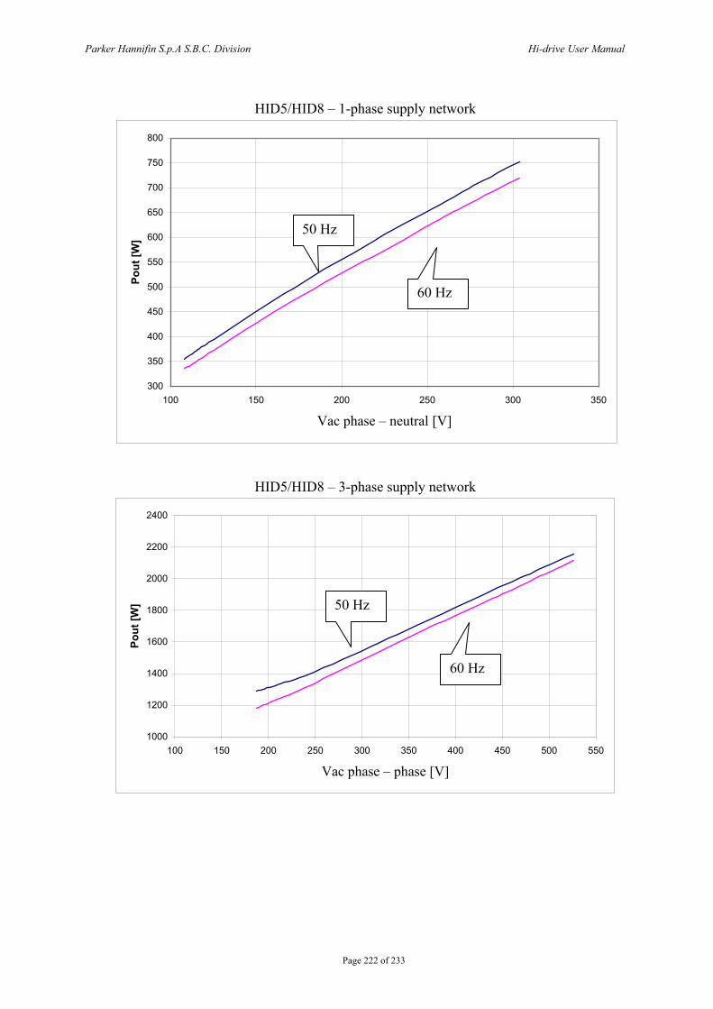
Parker Hannifin S.p.A S.B.C. Division Hi-drive User Manual
Page 222 of 233
HID5/HID8 – 1-phase supply network
300
350
400
450
500
550
600
650
700
750
800
100 150 200 250 300 350
Vac phase – neutral [V]
Pout
[W]
HID5/HID8 – 3-phase supply network
1000
1200
1400
1600
1800
2000
2200
2400
100 150 200 250 300 350 400 450 500 550
Vac phase – phase [V]
Pout
[W]
60 Hz
50 Hz
60 Hz
50 Hz
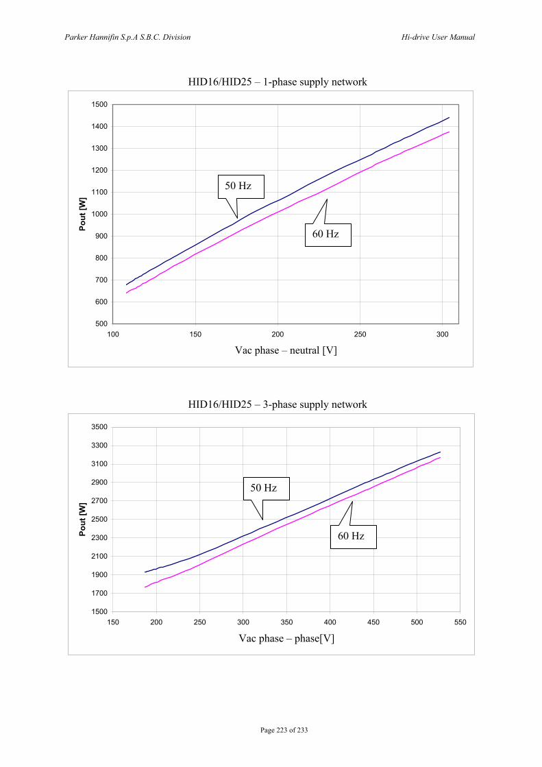
Parker Hannifin S.p.A S.B.C. Division Hi-drive User Manual
Page 223 of 233
HID16/HID25 – 1-phase supply network
500
600
700
800
900
1000
1100
1200
1300
1400
1500
100 150 200 250 300
Vac phase – neutral [V]
Pout
[W]
HID16/HID25 – 3-phase supply network
1500
1700
1900
2100
2300
2500
2700
2900
3100
3300
3500
150 200 250 300 350 400 450 500 550
Vac phase – phase[V]
Pout
[W]
60 Hz
50 Hz
60 Hz
50 Hz
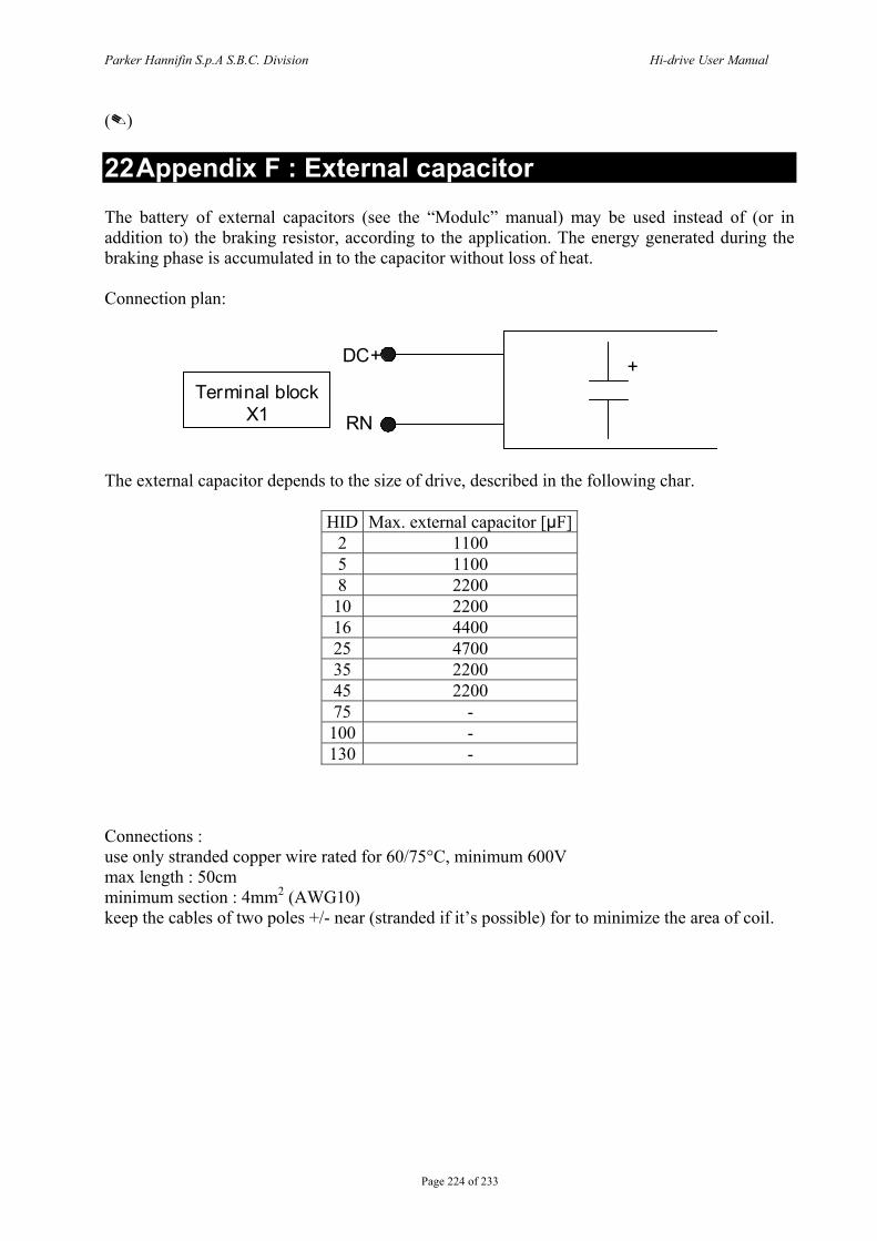
Parker Hannifin S.p.A S.B.C. Division Hi-drive User Manual
Page 224 of 233
()
22 Appendix F : External capacitor The battery of external capacitors (see the “Modulc” manual) may be used instead of (or in addition to) the braking resistor, according to the application. The energy generated during the braking phase is accumulated in to the capacitor without loss of heat. Connection plan:
DC +
RN
+ Terminal block
X1
The external capacitor depends to the size of drive, described in the following char.
HID Max. external capacitor [µF]2 1100 5 1100 8 2200 10 2200 16 4400 25 4700 35 2200 45 2200 75 - 100 - 130 -
Connections : use only stranded copper wire rated for 60/75°C, minimum 600V max length : 50cm minimum section : 4mm2 (AWG10) keep the cables of two poles +/- near (stranded if it’s possible) for to minimize the area of coil.
Parker Hannifin S.p.A S.B.C. Division Hi-drive User Manual
Page 225 of 233
23 Appendix G : Option “R” for safe disable function
23.1 Introduction The drive ordered with “R” option are manufactured and validated to implement category 3 safety disable as described in EN 954-1 and EN 13849-1 By mean of this function it is possible to guarantee that unwanted restart of the motor movements will not be allowed, even without using electromechanical switches between drive and motor. Drives labelled with “R” options are equipped of a electromechanical safety relay (certified by TÜV institute). This relay, driven by user, turns off safely power semiconductor stage and gives back a feedback though a free potential switch (normally closed). The safe disable turns off the output power through an electromechanical action, independent from drive firmware. In TWIN-N drives both axes output power stages are switched off using a unique signal.
The safe disable function prevent from torque generation in an squirrel cage induction motor connected to the drive even if a drive fault does occur. If a permanent magnet synchronous motor (brushless) is connected, a short rotation may occurs: 180° maximum, that becomes 90° maximum in case of salient poles technology motors. Machines risk assessment activity must take care of this fact.
The safe disable function do not provide an electrical shock prevention, so in case of service activity on electrical connections, electrical power must be disconnected from drive and operator must wait for the complete discharge of all internal capacitors (almost 6 minutes).
The safe disable function inhibit the power stage of the drive including dynamic brake power stage: for this reason when the safe disable signal is activated a fast emergency stop will not be allowed.
WWAARRNNIINNGG
WWAARRNNIINNGG
WWAARRNNIINNGG
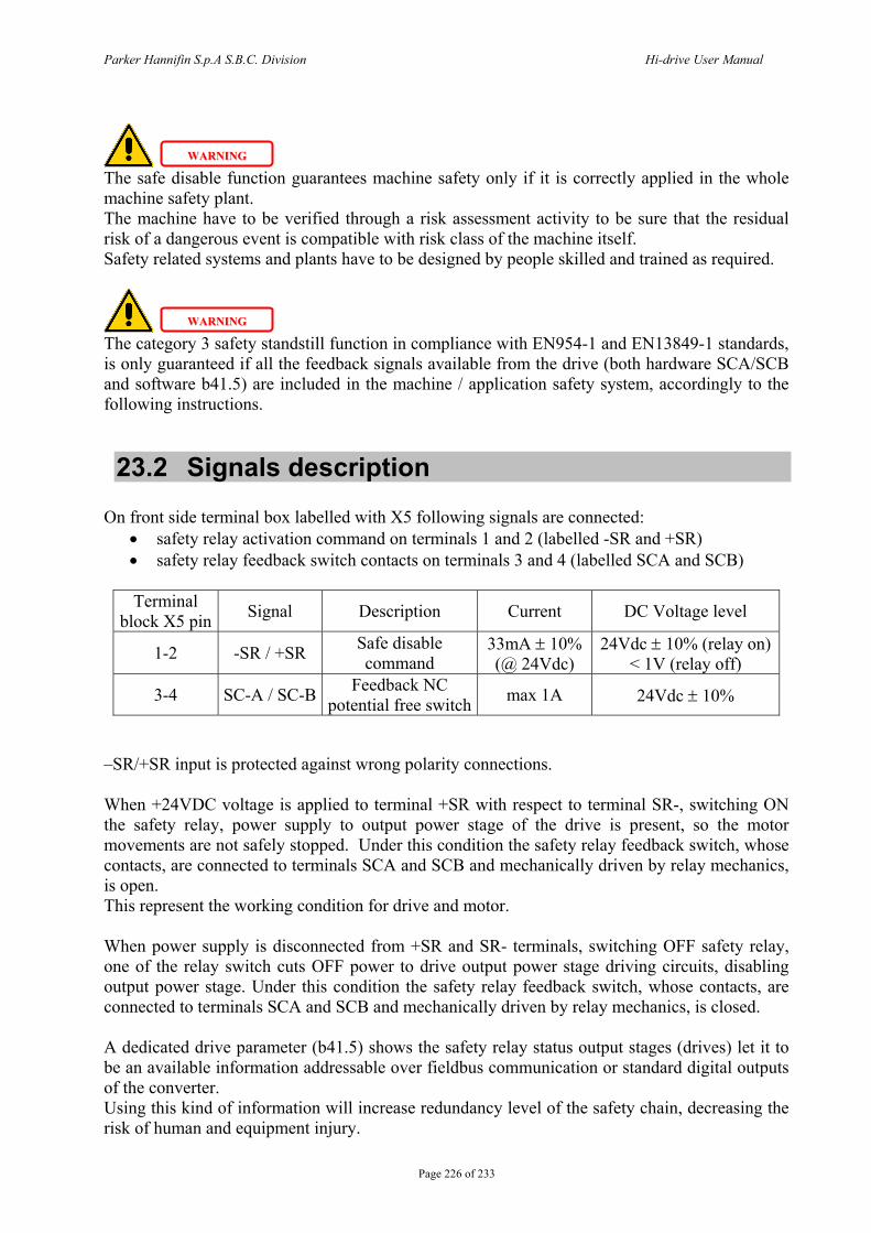
Parker Hannifin S.p.A S.B.C. Division Hi-drive User Manual
Page 226 of 233
The safe disable function guarantees machine safety only if it is correctly applied in the whole machine safety plant. The machine have to be verified through a risk assessment activity to be sure that the residual risk of a dangerous event is compatible with risk class of the machine itself. Safety related systems and plants have to be designed by people skilled and trained as required.
The category 3 safety standstill function in compliance with EN954-1 and EN13849-1 standards, is only guaranteed if all the feedback signals available from the drive (both hardware SCA/SCB and software b41.5) are included in the machine / application safety system, accordingly to the following instructions.
23.2 Signals description On front side terminal box labelled with X5 following signals are connected:
• safety relay activation command on terminals 1 and 2 (labelled -SR and +SR) • safety relay feedback switch contacts on terminals 3 and 4 (labelled SCA and SCB)
Terminal
block X5 pin Signal Description Current DC Voltage level
1-2 -SR / +SR Safe disable command
33mA ± 10% (@ 24Vdc)
24Vdc ± 10% (relay on) < 1V (relay off)
3-4 SC-A / SC-B Feedback NC potential free switch max 1A 24Vdc ± 10%
–SR/+SR input is protected against wrong polarity connections. When +24VDC voltage is applied to terminal +SR with respect to terminal SR-, switching ON the safety relay, power supply to output power stage of the drive is present, so the motor movements are not safely stopped. Under this condition the safety relay feedback switch, whose contacts, are connected to terminals SCA and SCB and mechanically driven by relay mechanics, is open. This represent the working condition for drive and motor. When power supply is disconnected from +SR and SR- terminals, switching OFF safety relay, one of the relay switch cuts OFF power to drive output power stage driving circuits, disabling output power stage. Under this condition the safety relay feedback switch, whose contacts, are connected to terminals SCA and SCB and mechanically driven by relay mechanics, is closed. A dedicated drive parameter (b41.5) shows the safety relay status output stages (drives) let it to be an available information addressable over fieldbus communication or standard digital outputs of the converter. Using this kind of information will increase redundancy level of the safety chain, decreasing the risk of human and equipment injury.
WWAARRNNIINNGG
WWAARRNNIINNGG
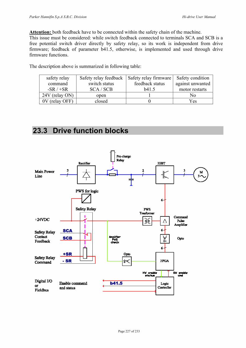
Parker Hannifin S.p.A S.B.C. Division Hi-drive User Manual
Page 227 of 233
Attention: both feedback have to be connected within the safety chain of the machine. This issue must be considered: while switch feedback connected to terminals SCA and SCB is a free potential switch driver directly by safety relay, so its work is independent from drive firmware; feedback of parameter b41.5, otherwise, is implemented and used through drive firmware functions. The description above is summarized in following table:
safety relay command -SR / +SR
Safety relay feedback switch status SCA / SCB
Safety relay firmware feedback status
b41.5
Safety condition against unwanted
motor restarts 24V (relay ON) open 1 No 0V (relay OFF) closed 0 Yes
23.3 Drive function blocks
+SR - SR
SCA
SCB
b41.5
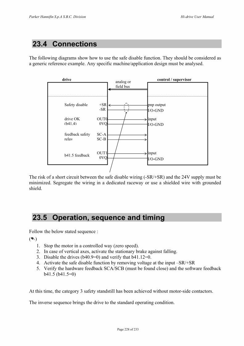
Parker Hannifin S.p.A S.B.C. Division Hi-drive User Manual
Page 228 of 233
23.4 Connections The following diagrams show how to use the safe disable function. They should be considered as a generic reference example. Any specific machine/application design must be analysed. The risk of a short circuit between the safe disable wiring (-SR/+SR) and the 24V supply must be minimized. Segregate the wiring in a dedicated raceway or use a shielded wire with grounded shield.
23.5 Operation, sequence and timing Follow the below stated sequence : ()
1. Stop the motor in a controlled way (zero speed). 2. In case of vertical axes, activate the stationary brake against falling. 3. Disable the drives (b40.9=0) and verify that b41.12=0. 4. Activate the safe disable function by removing voltage at the input –SR/+SR 5. Verify the hardware feedback SCA/SCB (must be found close) and the software feedback
b41.5 (b41.5=0)
At this time, the category 3 safety standstill has been achieved without motor-side contactors. The inverse sequence brings the drive to the standard operating condition.
drive control / supervisor analog or field bus
SC-A SC-B
+SR -SR
OUT1 0VQ
OUT0 0VQ
drive OK (b41.4)
Safety disable
feedback safety relay
b41.5 feedback
I/O-GND
I/O-GND
I/O-GND
pnp output
input
input
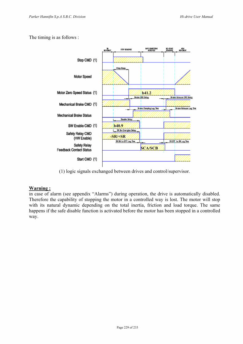
Parker Hannifin S.p.A S.B.C. Division Hi-drive User Manual
Page 229 of 233
The timing is as follows :
(1) logic signals exchanged between drives and control/supervisor.
Warning : in case of alarm (see appendix “Alarms”) during operation, the drive is automatically disabled. Therefore the capability of stopping the motor in a controlled way is lost. The motor will stop with its natural dynamic depending on the total inertia, friction and load torque. The same happens if the safe disable function is activated before the motor has been stopped in a controlled way.
b41.2
b40.9
-SR/+SR
SCA/SCB
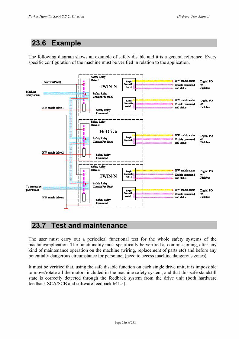
Parker Hannifin S.p.A S.B.C. Division Hi-drive User Manual
Page 230 of 233
23.6 Example The following diagram shows an example of safety disable and it is a general reference. Every specific configuration of the machine must be verified in relation to the application.
23.7 Test and maintenance The user must carry out a periodical functional test for the whole safety systems of the machine/application. The functionality must specifically be verified at commissioning, after any kind of maintenance operation on the machine (wiring, replacement of parts etc) and before any potentially dangerous circumstance for personnel (need to access machine dangerous zones). It must be verified that, using the safe disable function on each single drive unit, it is impossible to move/rotate all the motors included in the machine safety system, and that this safe standstill state is correctly detected through the feedback system from the drive unit (both hardware feedback SCA/SCB and software feedback b41.5).
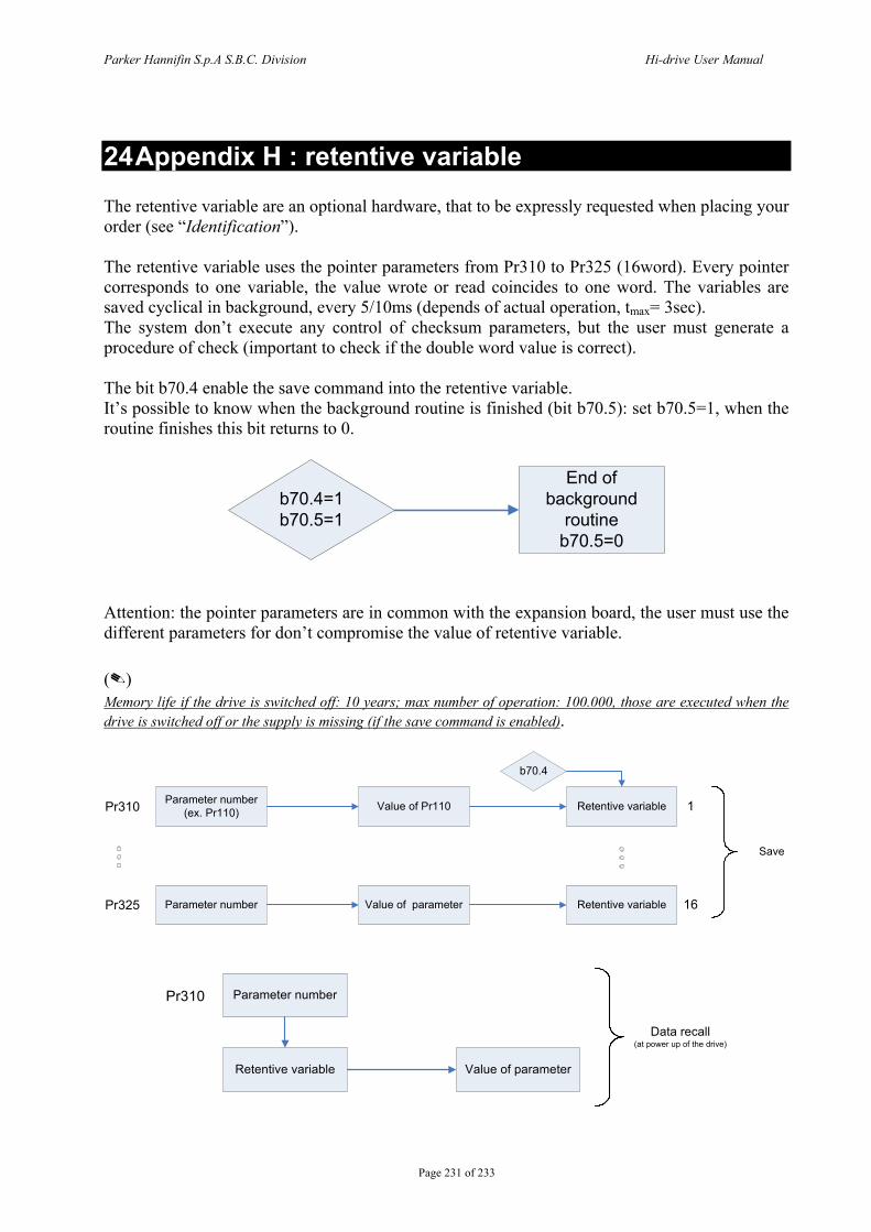
Parker Hannifin S.p.A S.B.C. Division Hi-drive User Manual
Page 231 of 233
24 Appendix H : retentive variable The retentive variable are an optional hardware, that to be expressly requested when placing your order (see “Identification”). The retentive variable uses the pointer parameters from Pr310 to Pr325 (16word). Every pointer corresponds to one variable, the value wrote or read coincides to one word. The variables are saved cyclical in background, every 5/10ms (depends of actual operation, tmax= 3sec). The system don’t execute any control of checksum parameters, but the user must generate a procedure of check (important to check if the double word value is correct). The bit b70.4 enable the save command into the retentive variable. It’s possible to know when the background routine is finished (bit b70.5): set b70.5=1, when the routine finishes this bit returns to 0.
b70.4=1b70.5=1
End of background
routineb70.5=0
Attention: the pointer parameters are in common with the expansion board, the user must use the different parameters for don’t compromise the value of retentive variable. () Memory life if the drive is switched off: 10 years; max number of operation: 100.000, those are executed when the drive is switched off or the supply is missing (if the save command is enabled).
Parameter number (ex. Pr110)Pr310 Value of Pr110 Retentive variable
b70.4
1
16Parameter numberPr325 Value of parameter Retentive variable
Save
Parameter number Pr310
Retentive variable Value of parameter
Data recall(at power up of the drive)
Parker Hannifin S.p.A S.B.C. Division Hi-drive User Manual
Page 232
25 History of manual revisions Any time the manual is updated, the new or modified parts are identified by a symbol () beside the text. Rev. 0 November 2004 First edition: total pages: 150 Rev. 0.1 October 2005 Introduction of the product HID35 and HID45 Programmable outputs adjourned Rev. 0.2 December 2006 CANopen DSP402 HID75, 100 and 130: characteristics, dimensions, connections Option “R” External capacitor Safety instructions Identification Motor with emergency brake Phasing procedure for encoder with EnDat or Hiperface interface and motor
phases Retentive variable Pr51 and Pr53 EU standard 2002/96/EC Rev. 0.3 February 2008 Encoder + Hall sensor, SinCos (one sin wave per pole pitch) Encoder CAN OPM122 and ramp with “S” profile b40.11, Pr37, b41.14 Rev. 0.4 July 2008 Speed window: b40.7, b41.0, b41.1, b41.2, b41.3 b39.6, b39.12 Rev. 0.5 May 2009 Technical data: size 4/5 Parameters b39.6 Option “R”: relay status (par. 5) Retentive variable: memory life Rev. 0.6 April 2010 Hiperface cable, HALL sensor cable HID155 and HID250 CANopen DS402: objects 0x2065, 0x2066 and bit b78.4 External capacitor per HID25: 4700µF OPM122 For other informations log into website www.sbcelettronica.com. Arranges to the manual data can be made by the manufacturer without advance notice. The data shown in the manual correspond to the specifications relating to the revision date


![GGIORNAMENTO 2013/1 CONTENUTO - Marola Attrezzature · 2017. 10. 12. · SBC (Sensotronic Brake Control) 3 . 6 [E 64] Cabrio . Exhaust gas treatment . Particulate filter 1.0 . 6 [E](https://static.fdocumenti.com/doc/165x107/611d7dbb72bf0604af65bc00/ggiornamento-20131-contenuto-marola-2017-10-12-sbc-sensotronic-brake-control.jpg)