SBC SRL 86 20098 San Giuliano Milanese Milano Italy ISDN · via LeoneTolstoj, 86 20098 San Giuliano...
8
SBC SRL via LeoneTolstoj, 86 20098 San Giuliano Milanese Milano‐Italy Capitale Sociale 70.200,00 VAT n° IT08192530155 e‐mail sbc@sbc‐it.com PEC [email protected] Visit us at www.sbc‐it.eu ISDN Phone. +39 02 98.49.16.76 Fax +39 02 98.49.17.12 San Giuliano
Transcript of SBC SRL 86 20098 San Giuliano Milanese Milano Italy ISDN · via LeoneTolstoj, 86 20098 San Giuliano...
SBC SRL via LeoneTolstoj, 86
20098 San Giuliano MilaneseMilano‐Italy
Capitale Sociale 70.200,00 VAT n° IT08192530155
e‐mail sbc@sbc‐it.com PEC [email protected]
Visit us at www.sbc‐it.eu
ISDN
Phone. +39 02 98.49.16.76
Fax +39 02 98.49.17.12
San Giuliano
Enrico
Casella di testo
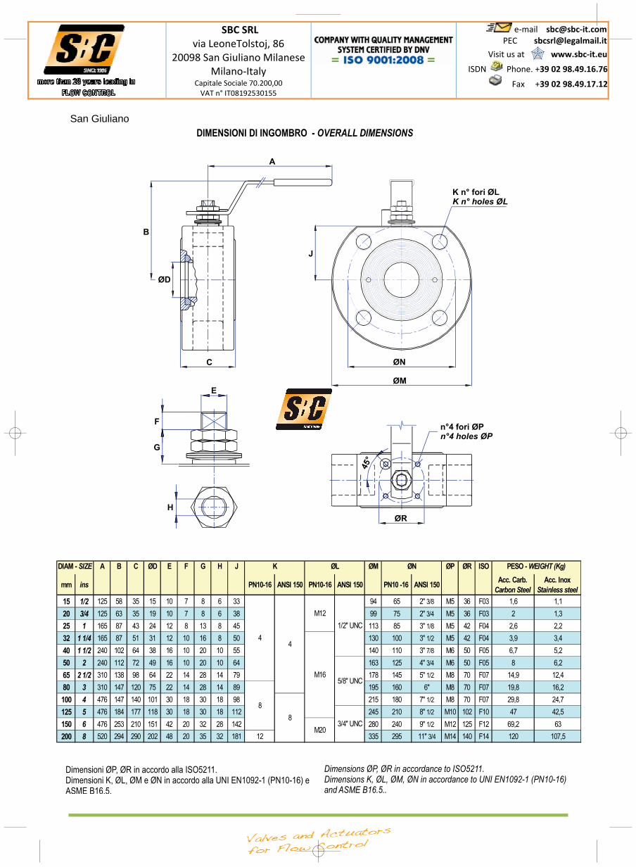
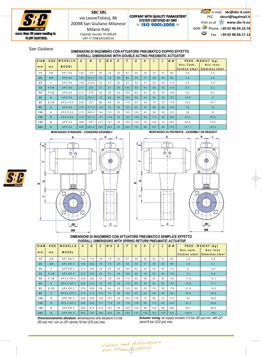
VALVOLE A SFERA A CORPO PIATTO COMPLETE DI ATTUATORE PNEUMATICO WAFER TYPE BALL VALVE COMPLETE WITH PNEUMATIC ACTUATOR
Enrico
Casella di testo
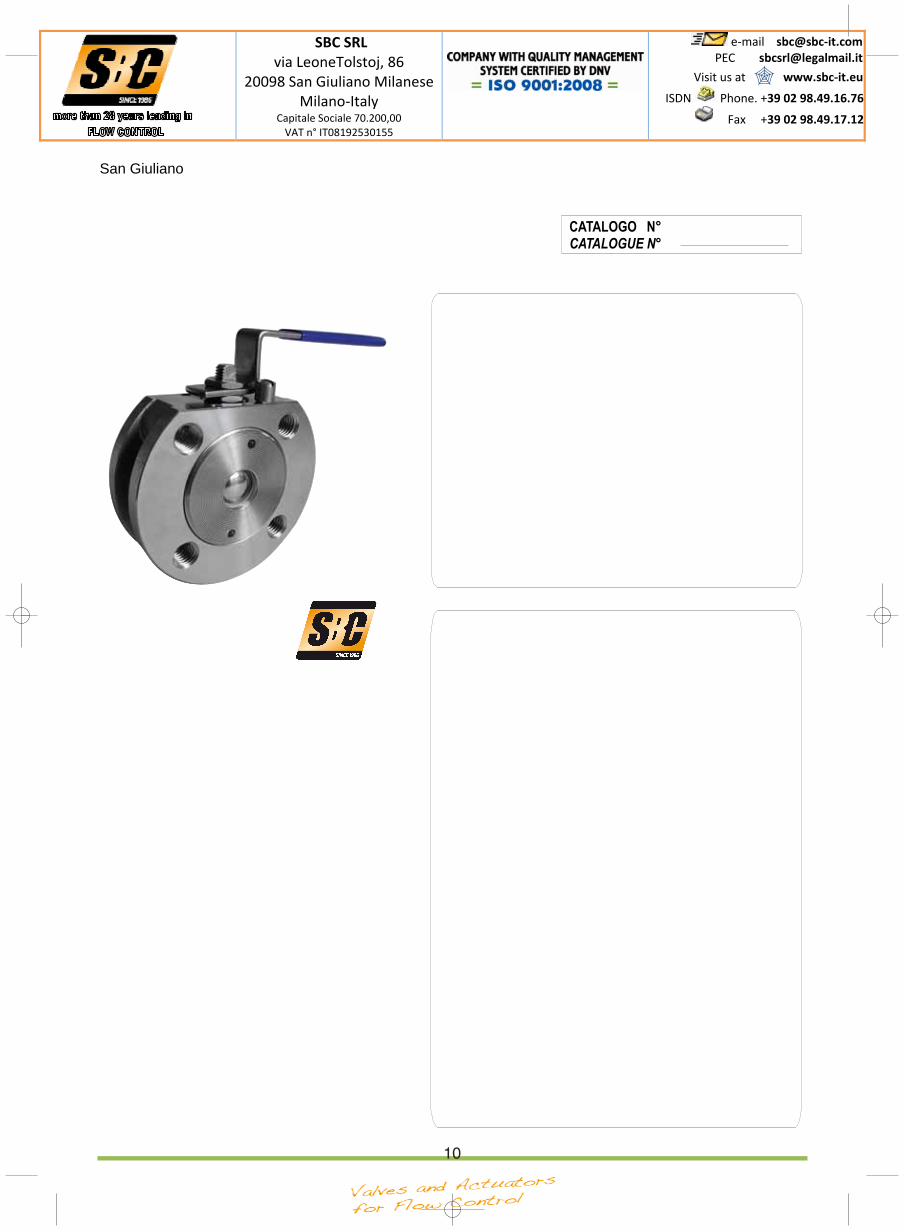
VALVOLE A SFERA A CORPO PIATTO CON LEVA MANUALE WAFER TYPE BALL VALVE WITH LEVER OPERATOR
SBC SRL via LeoneTolstoj, 86
20098 San Giuliano MilaneseMilano‐Italy
Capitale Sociale 70.200,00 VAT n° IT08192530155
e‐mail sbc@sbc‐it.com PEC [email protected]
Visit us at www.sbc‐it.eu
ISDN
Phone. +39 02 98.49.16.76
Fax +39 02 98.49.17.12
San Giuliano
4
1
3
4
5
6
2
1
2
3
4
5
6
CARATTERISTICHE GENERALI
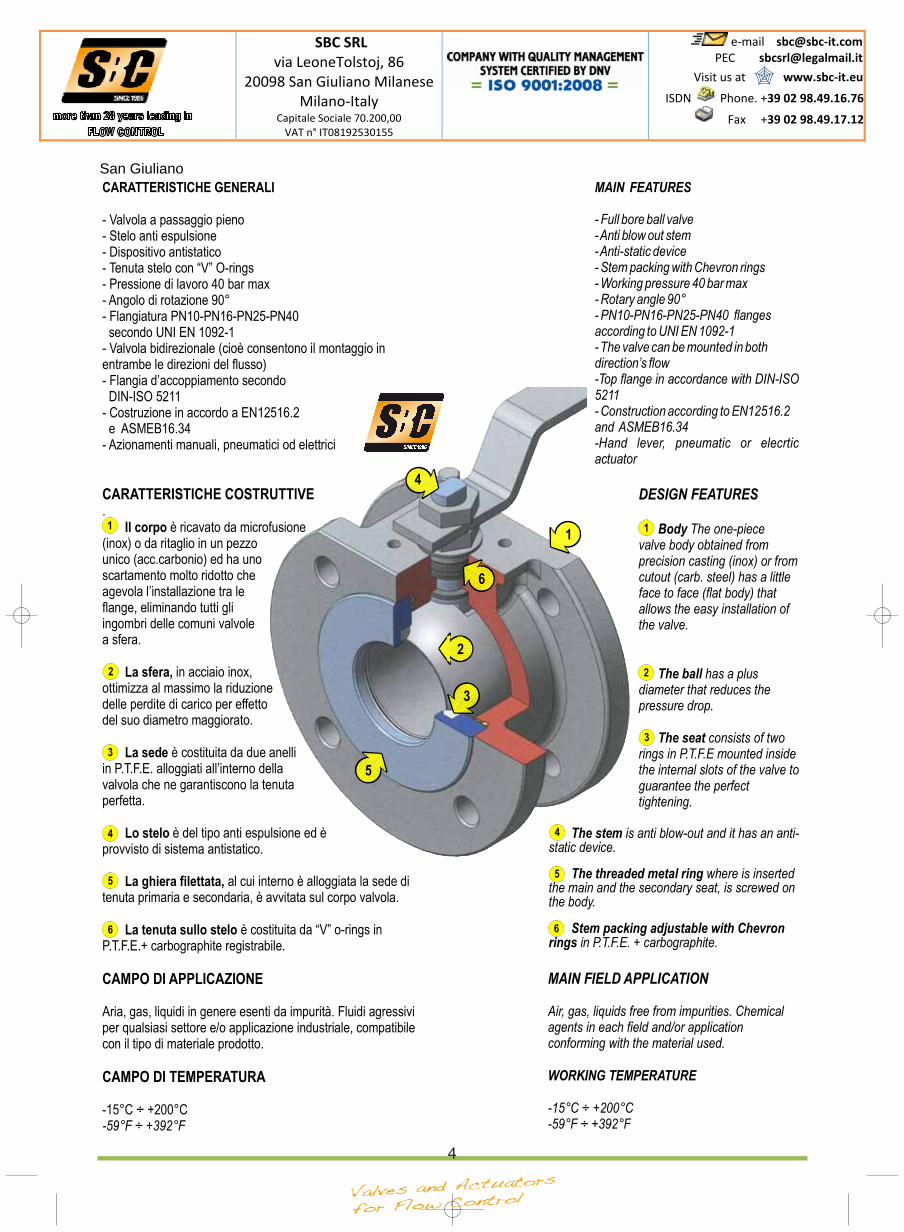
Il corpo
La sfera,
La sede
Lo stelo
La ghiera filettata,
La tenuta sullo stelo
- Valvola a passaggio pieno- Stelo anti espulsione- Dispositivo antistatico- Tenuta stelo con “V” O-rings- Pressione di lavoro 40 bar max- Angolo di rotazione 90°- Flangiatura PN10-PN16-PN25-PN40
secondo UNI EN 1092-1- Valvola bidirezionale (cioè consentono il montaggio inentrambe le direzioni del flusso)- Flangia d’accoppiamento secondo
DIN-ISO 5211- Costruzione in accordo a EN12516.2
e ASMEB16.34- Azionamenti manuali, pneumatici od elettrici
.è ricavato da microfusione
(inox) o da ritaglio in un pezzounico (acc.carbonio) ed ha unoscartamento molto ridotto cheagevola l’installazione tra leflange, eliminando tutti gliingombri delle comuni valvolea sfera.
in acciaio inox,ottimizza al massimo la riduzionedelle perdite di carico per effettodel suo diametro maggiorato.
è costituita da due anelliin P.T.F.E. alloggiati all’interno dellavalvola che ne garantiscono la tenutaperfetta.
è del tipo anti espulsione ed èprovvisto di sistema antistatico.
al cui interno è alloggiata la sede ditenuta primaria e secondaria, è avvitata sul corpo valvola.
è costituita da “V” o-rings inP.T.F.E.+ carbographite registrabile.
Aria, gas, liquidi in genere esenti da impurità. Fluidi agressiviper qualsiasi settore e/o applicazione industriale, compatibilecon il tipo di materiale prodotto.
-15°C ÷ +200°C
CARATTERISTICHE COSTRUTTIVE
CAMPO DI APPLICAZIONE
CAMPO DI TEMPERATURA
-59°F ÷ +392°F
DESIGN FEATURES
Body
The ball
The seat
The one-piecevalve body obtained fromprecision casting (inox) or fromcutout (carb. steel) has a littleface to face (flat body) thatallows the easy installation ofthe valve.
has a plusdiameter that reduces thepressure drop.
consists of tworings in P.T.F.E mounted insidethe internal slots of the valve toguarantee the perfecttightening.
1
2
3
MAIN FEATURES
- Full bore ball valve-Anti blow out stem-Anti-static device- Stem packing with Chevron rings- Working pressure 40 bar max- Rotary angle 90°- PN10-PN16-PN25-PN40 flangesaccording to UNI EN 1092-1- The valve can be mounted in bothdirection’s flow-Top flange in accordance with DIN-ISO5211- Construction according to EN12516.2and ASMEB16.34-Hand lever, pneumatic or elecrticactuator
4
5
6
is anti blow-out and it has an anti-static device.
where is insertedthe main and the secondary seat, is screwed onthe body.
in P.T.F.E. + carbographite.
The stem
The threaded metal ring
Stem packing adjustable with Chevronrings
MAIN FIELD APPLICATION
Air, gas, liquids free from impurities. Chemicalagents in each field and/or applicationconforming with the material used.
-15°C ÷ +200°C-59°F ÷ +392°F
WORKING TEMPERATURE
SBC SRL via LeoneTolstoj, 86
20098 San Giuliano MilaneseMilano‐Italy
Capitale Sociale 70.200,00 VAT n° IT08192530155
e‐mail sbc@sbc‐it.com PEC [email protected]
Visit us at www.sbc‐it.eu
ISDN
Phone. +39 02 98.49.16.76
Fax +39 02 98.49.17.12
San Giuliano
SBC SRL via LeoneTolstoj, 86
20098 San Giuliano MilaneseMilano‐Italy
Capitale Sociale 70.200,00 VAT n° IT08192530155
e‐mail sbc@sbc‐it.com PEC [email protected]
Visit us at www.sbc‐it.eu
ISDN
Phone. +39 02 98.49.16.76
Fax +39 02 98.49.17.12
San Giuliano
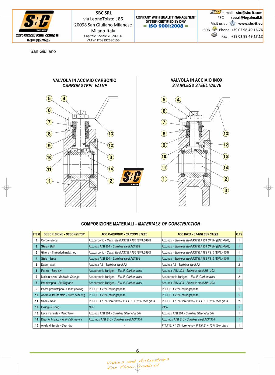
VALVOLA IN ACCIAIO CARBONIOCARBON STEEL VALVE
1 2
3
45
6
7
8
9
10
11
12
13
14
VALVOLA IN ACCIAIO INOXSTAINLESS STEEL VALVE
1 2
3
45
6
7
8
9
10
11
12
13
14
15
ITEM DESCRIZIONE - DESCRIPTION ACC.CARBONIO - CARBON STEEL ACC.INOX - STAINLESS STEEL Q.TY
1 Corpo - Body Acc.carbonio - Carb. Steel ASTM A105 (EN1.0460) Acc.inox - Stainless steel ASTM A351 CF8M (EN1.4408) 1
2 Sfera - Ball Acc.inox AISI 304 - Stainless steel AISI304 Acc.inox - Stainless steel ASTM A351 CF8M (EN1.4408) 1
3 Ghiera - Threaded metal ring Acc.carbonio - Carb. Steel ASTM A105 (EN1.0460) Acc.inox - Stainless steel ASTM A182 F316 (EN1.4401) 1
4 Stelo - Stem Acc.inox AISI 304 - Stainless steel AISI304 Acc.inox - Stainless steel ASTM A182 F316 (EN1.4401) 1
5 Dado - Nut Acc.inox A2 - Stainless steel A2 Acc.inox A2 - Stainless steel A2 2
6 Fermo - Stop pin Acc.carbonio kanigen. - E.N.P. Carbon steel Acc.inox AISI 303 - Stainless steel AISI 303 1
7 Molle a tazza - Belleville Springs Acc.carbonio kanigen. - E.N.P. Carbon steel Acc.carbonio kanigen. - E.N.P. Carbon steel 2
8 Premistoppa - Stuffing box Acc.carbonio kanigen. - E.N.P. Carbon steel Acc.inox AISI 303 - Stainless steel AISI 303 1
9 Pacco premistoppa - Gland packing P.T.F.E. + 25% carbographite P.T.F.E. + 25% carbographite 1
10 Anello di tenuta stelo - Stem seal ring P.T.F.E. + 25% carbographite P.T.F.E. + 25% carbographite 1
11 Sede - Seal P.T.F.E. + 15% fibre vetro - P.T.F.E. + 15% fiber glass P.T.F.E. + 15% fibre vetro - P.T.F.E. + 15% fiber glass 2
12 O-ring - O-ring NBR Viton 1
13 Leva manuale - Hand lever Acc.inox AISI 304 - Stainless Steel AISI 304 Acc.inox AISI 304 - Stainless Steel AISI 304 1
14 Disp. Antistatico - Anti-static device Acc. Inox AISI 316 - Stainless steel AISI 316 Acc. Inox AISI 316 - Stainless steel AISI 316 1
15 Anello di tenuta - Seal ring - P.T.F.E. + 15% fibre vetro - P.T.F.E. + 15% fiber glass 1
COMPOSIZIONE MATERIALI - MATERIALS OF CONSTRUCTION
6
SBC SRL via LeoneTolstoj, 86
20098 San Giuliano MilaneseMilano‐Italy
Capitale Sociale 70.200,00 VAT n° IT08192530155
e‐mail sbc@sbc‐it.com PEC [email protected]
Visit us at www.sbc‐it.eu
ISDN
Phone. +39 02 98.49.16.76
Fax +39 02 98.49.17.12
San Giuliano
ISTRUZIONI PER L’INSTALLAZIONE
MANUTENZIONE
ATTENZIONE
Occorre innanzitutto accertarsi che le tubazioni siano esenti da impurità.Le flange devono essere sempre perfettamente parallele, con superficiben lavorate. Non sottoporre la valvola a urti o colpi che ne danneggianoil buon funzionamento. Non sottoporre la valvola a fonti di calore (Fuoco-Resistenze-ecc.). Verificare che la distanza tra le flange abbia la stessadimensione dello scartamento della valvola; in ogni caso occorredistanziare con appositi strumenti le flange per consentire un facileinserimento della valvola senza danneggiarne le parti esterne.Posizionare la valvola tra le flange e serrare parzialmente i bulloni.Completare il serraggio dei bulloni in modo incrociato, portando le flangein battuta sul corpo della valvola senza applicare ulteriore precarico.Dopo l’installazione, la valvola deve essere aperta e chiusacompletamente per confermare che l’installazione è avvenutacorrettamente.
Prima di procedere alla manutenzione, munirsi di adeguatoabbigliamento protettivo. Utilizzare per ogni intervento attrezzature inconformità alle norme di sicurezza. Nel caso in cui ci siano condizioni diutilizzo estreme e/o gravose è consigliabile intensificare il controllo e leoperazioni di manutenzione. Rimuovere la valvola dall’impianto e pulirladai residui del prodotto impiegato, specie se tossico o comunque nocivo.Bloccare la valvola in morsa e ruotare la sfera in posizione di “valvolachiusa” mediante la leva.
Contrassegnare la posizione tra corpo(1) e laghiera(3) tracciando una linea di fede a mezzo della punta da segno.Svitare e togliere la ghiera(3) a mezzo chiavi, quindi sollevare e toglierela guarnizione(12) e dove presente (valvola INOX) anche l’anello ditenuta(15), utilizzando appositi strumenti. Togliere la prima sede ditenuta(11) presente nell’alloggiamento della ghiera, pulirlaaccuratamente e se rovinata procedere alla sostituzione. Estrarre lasfera(2), esaminarne l’intera superficie esterna e se rigata o comunquedanneggiata procedere alla sostituzione. Togliere la seconda sede ditenuta presente nell’alloggiamento interno del corpo(11), pulirlaaccuratamente e se rovinata procedere alla sostituzione. Svitare etogliere i dadi di fissaggio(5) dallo stelo di manovra(4). Sfilare le molle atazza(7), il premistoppa(8) e poi con un apposito strumento rimuovere ilPacco a “V” (9), se danneggiate, sostituire le parti. Sfilare dall’interno lostelo di manovra(4) ed il rispettivo anello di tenuta(10), dopo averliesaminati con cura, se danneggiati, procedere con la sostituzione.Rimontare lo stelo con il proprio anello di tenuta, inserendolodall’interno. Rimontare gli altri componenti nell’ordine inverso a quellodello smontaggio. Dopo aver inserito anche le sedi di tenuta, e la sfera,eseguire con cautela alcune manovre per garantire la rotazione inposizione della sfera. Posizionare nel relativo alloggiamento laguarnizione (ed eventualmente anche l’anello di tenuta). Avvitare conchiavi a spina speciali la ghiera fino a raggiungere l’allineamentooriginale. Verificare che la rotazione della sferaAPERTURA/CHIUSURAdella valvola presenti una rotazione di manovra omogenea. Pulirel’interno delle tubazioni verificando che non vi siano residui vari chepossano danneggiare le sedi di tenuta.
- La società decli na ogni responsabilitàall’atto della manutenzione per problematiche conseguenti alla stessa,alla errata valutazione dei particolari non sostituiti e di quelli sostituiti inmodo improprio o scorretto.- La società si riserva la facoltà di interrompere o modificare i particolari ela costruzione di un suo prodotto, senza alcun obbligo di sostituire omontare le parti modificate sui prodotti gia forniti.
In caso di valvola attuata, rimuoverel’operatore ed effettuare la rotazione della sfera utilizzando unanormale chiave inglese.
Before starting the installation of the valve, check carefully the good
cleaning condition of the piping. The flanges must be always perfectly
parallel, with surfaces machined very well. Do not hit or strike the valve.
Do not overheat the valve (Fire, Resistences-etc.). Make sure that the
distance between flanges is of the same dimension as the valve; in any
case during installation arrange an adeguate space to allow easy
insertion of the valve without damaging outside parts. After Putting the
valve between flanges, screw partially the bolts. Complete the screwing
of the bolts crosswise, by applying and adequate torque, without
excessive force. After installation, the valve may be opened and closed
fully to confirm satisfactory operation.
Before starting maintenance, please wear protective apparel. Use for
every operation equipments in compliance with safety norms. Under
hard working conditions intensive maintenance may be required.
Remove the valve from the piping and clean it inside (specially when the
working flow is toxic or harmful). Block the valve and turn the ball in
“close position” using a lever.
Mark the
position between the body(1) and the metal ring (3) with an external
liner on the surfaces. Screwing-off the metal ring(3) using the wrench,
so remove the seal(12) and if present (stainless steel valve) remove the
seal ring(15) using special fixtures. Remove the first seat(11) placed
inside the internal slot of the plug, clean it and if damaged, change itself.Extract the ball(2), check carefully all its external surface and if
damaged change it. Remove the second seat(11) placed in the internal
slot of the body), clean it and, if damaged, change it. Screwing-off the
stop nuts(5) from the stem(4). Remove the spring washers(7), the
pressing bush(8) and using a suitable fixture, remove the chevron
rings(9); if necessary, change the damaged parts. Remove, towards
the internal way, the stem(4) and its seal ring(10), after checking, if
damaged, change them. Insert the stem with its seal ring. Introduce all
the components in reverse order respect of disassembly.After inserting
also the seats, the ball, execute some manoeuvres to guarantee the
rotation of the ball in correct position. Place inside its slots the o-ring
(and if present, insert the seal ring). Screw the plug with special pin-
wrench until you reach the alignment marked before. Check the rotation
of the ball OPEN/CLOSE makes a good manoeuvre. Before mounting
the valve, clean inside the piping.
If the valve is automatized, remove the
actuator and turn the ball using a common wrench.
INSTALLATION INSTRUCTIONS
MAINTENANCE
- SIRCA INTERNATIONAL s.p.a. refuses, during the maintenanceperformance, any responsability linked to consequent troubles, to anincorrect evaluation of the non substitutes pieces, or to thoseimproperly or incorrectly substituted.- SIRCA reserves the right to interrupt production and/or modifycomponents and/or construction of its product, without obligation tosubstitute or modify materials previously supplied.
ATTENTION
SBC SRL via LeoneTolstoj, 86
20098 San Giuliano MilaneseMilano‐Italy
Capitale Sociale 70.200,00 VAT n° IT08192530155
e‐mail sbc@sbc‐it.com PEC [email protected]
Visit us at www.sbc‐it.eu
ISDN
Phone. +39 02 98.49.16.76
Fax +39 02 98.49.17.12
San Giuliano
SBC SRL via LeoneTolstoj, 86
20098 San Giuliano MilaneseMilano‐Italy
Capitale Sociale 70.200,00 VAT n° IT08192530155
e‐mail sbc@sbc‐it.com PEC [email protected]
Visit us at www.sbc‐it.eu
ISDN
Phone. +39 02 98.49.16.76
Fax +39 02 98.49.17.12
San Giuliano
9
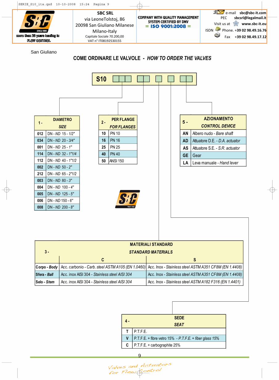
COME ORDINARE LE VALVOLE - HOW TO ORDER THE VALVES
SERIE_S10_ita.qxd 10-10-2008 15:24 Pagina 9
SBC SRL via LeoneTolstoj, 86
20098 San Giuliano MilaneseMilano‐Italy
Capitale Sociale 70.200,00 VAT n° IT08192530155
e‐mail sbc@sbc‐it.com PEC [email protected]
Visit us at www.sbc‐it.eu
ISDN
Phone. +39 02 98.49.16.76
Fax +39 02 98.49.17.12
San Giuliano
10
CATALOGO N°CATALOGUE N°