
Motoreductor catalogue
100
Products Media No. 4001 A04 Riduttori e motoriduttori a vite Worm gear reducers and gearmotors Edition December 2011
-
Upload
agapitiberius -
Category
Documents
-
view
102 -
download
0
description
Technical specifications and details for motoreductors
Transcript of Motoreductor catalogue
ProductsMedia No. 4001
A04Riduttori e motoriduttori a viteWorm gear reducers and gearmotors
Edition December 2011
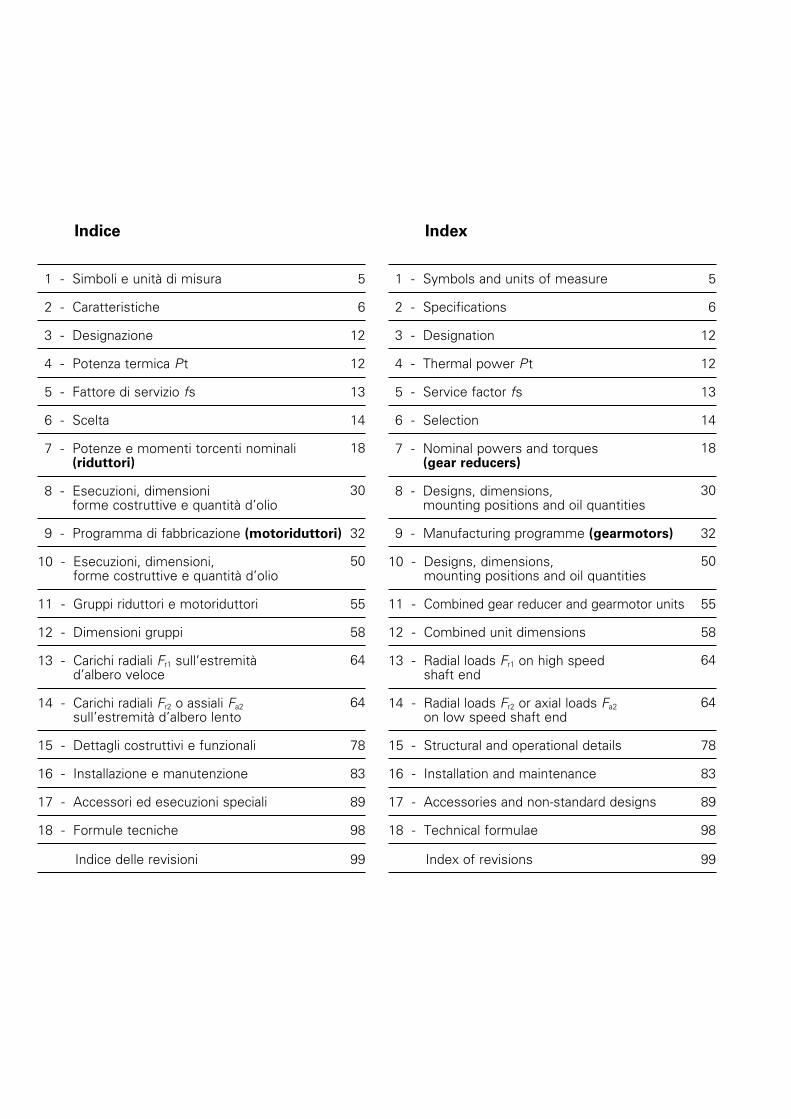
Indice
1 - Simboli e unità di misura 5
2 - Caratteristiche 6
3 - Designazione 12
4 - Potenza termica Pt 12
5 - Fattore di servizio fs 13
6 - Scelta 14
7 - Potenze e momenti torcenti nominali (riduttori)
18
8 - Esecuzioni, dimensioni forme costruttive e quantità d’olio
30
9 - Programma di fabbricazione (motoriduttori) 32
10 - Esecuzioni, dimensioni, forme costruttive e quantità d’olio
50
11 - Gruppi riduttori e motoriduttori 55
12 - Dimensioni gruppi 58
13 - Carichi radiali Fr1 sull’estremità d’albero veloce
64
14 - Carichi radiali Fr2 o assiali Fa2 sull’estremità d’albero lento
64
15 - Dettagli costruttivi e funzionali 78
16 - Installazione e manutenzione 83
17 - Accessori ed esecuzioni speciali 89
18 - Formule tecniche 98
Indice delle revisioni 99
Index
1 - Symbols and units of measure 5
2 - Specifications 6
3 - Designation 12
4 - Thermal power Pt 12
5 - Service factor fs 13
6 - Selection 14
7 - Nominal powers and torques (gear reducers)
18
8 - Designs, dimensions, mounting positions and oil quantities
30
9 - Manufacturing programme (gearmotors) 32
10 - Designs, dimensions, mounting positions and oil quantities
50
11 - Combined gear reducer and gearmotor units 55
12 - Combined unit dimensions 58
13 - Radial loads Fr1 on high speed shaft end
64
14 - Radial loads Fr2 or axial loads Fa2 on low speed shaft end
64
15 - Structural and operational details 78
16 - Installation and maintenance 83
17 - Accessories and non-standard designs 89
18 - Technical formulae 98
Index of revisions 99
3A04 December 2011
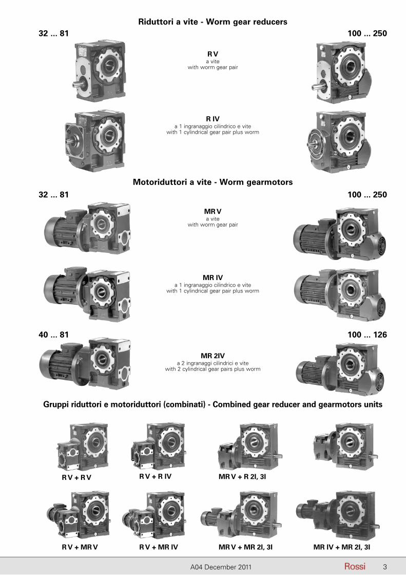
Riduttori a vite - Worm gear reducers
Motoriduttori a vite - Worm gearmotors
Gruppi riduttori e motoriduttori (combinati) - Combined gear reducer and gearmotors units
R Va vite
with worm gear pair
R IVa 1 ingranaggio cilindrico e vite
with 1 cylindrical gear pair plus worm
MR Va vite
with worm gear pair
MR IVa 1 ingranaggio cilindrico e vite
with 1 cylindrical gear pair plus worm
MR 2IVa 2 ingranaggi cilindrici e vite
with 2 cylindrical gear pairs plus worm
100 ... 250
32 ... 81 100 ... 250
40 ... 81
R V + R V R V + R IV MR V + R 2I, 3I
R V + MR V R V + MR IV MR V + MR 2I, 3I MR IV + MR 2I, 3I
100 ... 126
32 ... 81
4
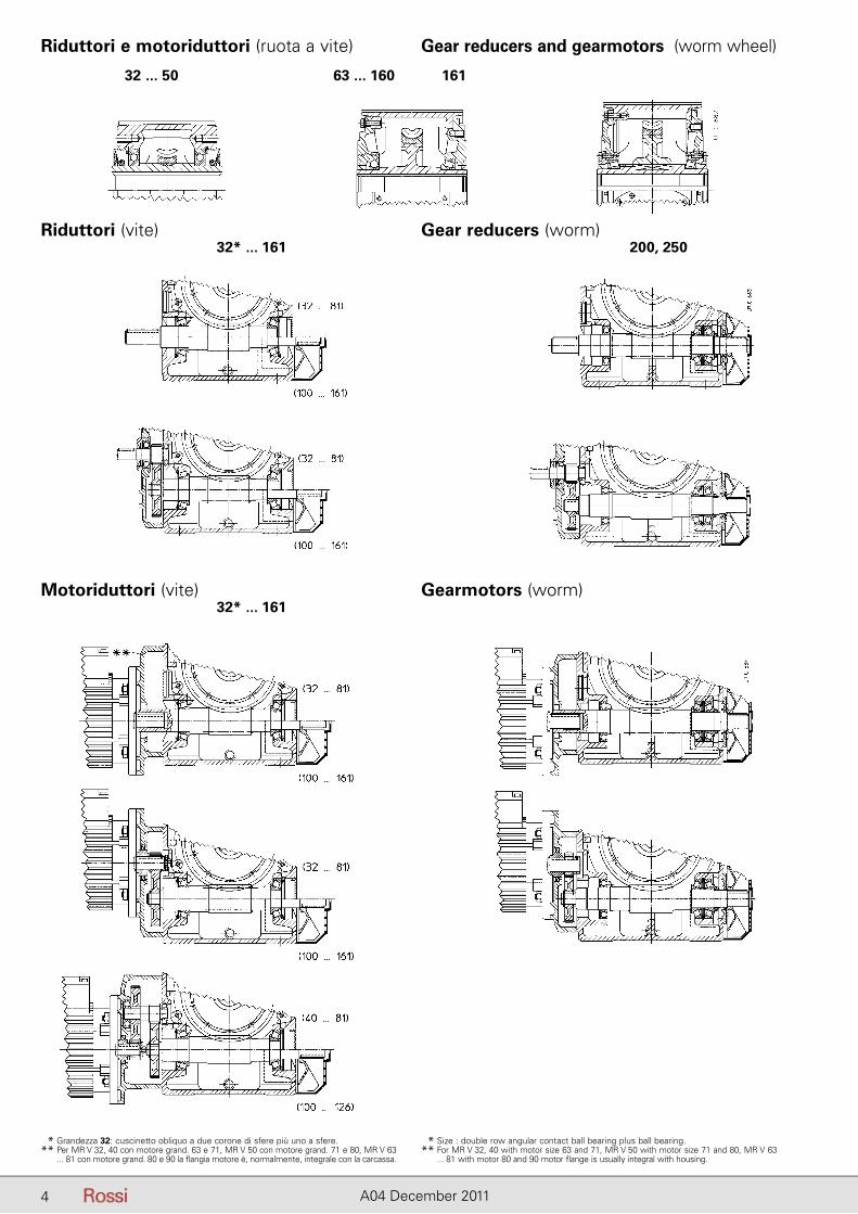
Riduttori e motoriduttori (ruota a vite)
Riduttori (vite) Gear reducers (worm)
Motoriduttori (vite) Gearmotors (worm)
Gear reducers and gearmotors (worm wheel)
32 ... 50
32* ... 161
32* ... 161
200, 250
63 ... 160 161
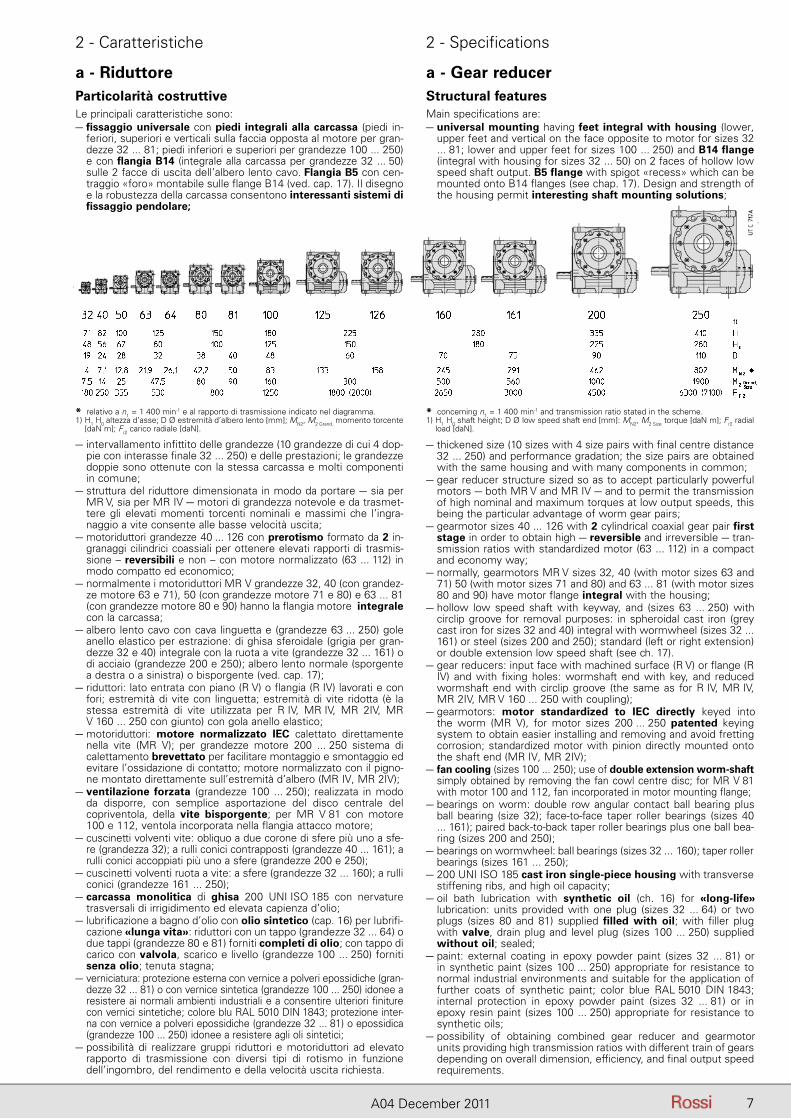
** Grandezza 32: cuscinetto obliquo a due corone di sfere più uno a sfere.** Per MR V 32, 40 con motore grand. 63 e 71, MR V 50 con motore grand. 71 e 80, MR V 63
... 81 con motore grand. 80 e 90 la flangia motore è, normalmente, integrale con la carcassa.
** Size : double row angular contact ball bearing plus ball bearing.** For MR V 32, 40 with motor size 63 and 71, MR V 50 with motor size 71 and 80, MR V 63
... 81 with motor 80 and 90 motor flange is usually integral with housing.
4 A04 December 2011
1 - Simboli e unità di misura 1 - Symbols and units of measure
5A04 December 2011
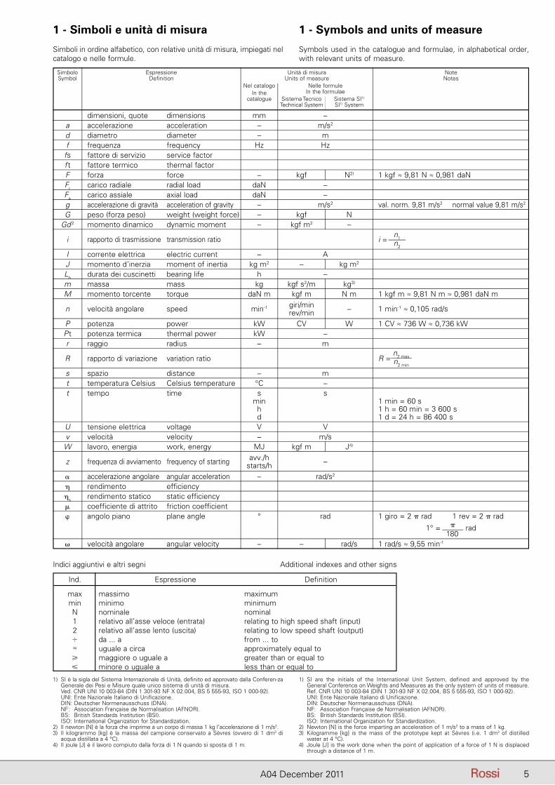
Simboli in ordine alfabetico, con relative unità di misura, impiegati nel catalogo e nelle formule.
Symbols used in the catalogue and formulae, in alphabetical order, with relevant units of measure.
Simbolo Espressione Unità di misura Note Symbol Definition Units of measure Notes Nel catalogo Nelle formule In the In the formulae catalogue Sistema Tecnico Sistema SI1)
Technical System SI1) System
dimensioni, quote dimensions mm – a accelerazione acceleration – m/s2
d diametro diameter – m f frequenza frequency Hz Hz fs fattore di servizio service factor f t fattore termico thermal factor F forza force – kgf N2) 1 kgf ≈ 9,81 N ≈ 0,981 daN Fr carico radiale radial load daN – Fa carico assiale axial load daN – g accelerazione di gravità acceleration of gravity – m/s2 val. norm. 9,81 m/s2 normal value 9,81 m/s2
G peso (forza peso) weight (weight force) – kgf N Gd 2 momento dinamico dynamic moment – kgf m2 –
i rapporto di trasmissione transmission ratio i =
n1n2
I corrente elettrica electric current – A J momento d’inerzia moment of inertia kg m2 – kg m2
Lh durata dei cuscinetti bearing life h – m massa mass kg kgf s2/m kg3)
M momento torcente torque daN m kgf m N m 1 kgf m ≈ 9,81 N m ≈ 0,981 daN m
n velocità angolare speed min-1 giri/min – 1 min-1 ≈ 0,105 rad/s rev/min P potenza power kW CV W 1 CV ≈ 736 W ≈ 0,736 kW P t potenza termica thermal power kW – r raggio radius – m
R rapporto di variazione variation ratio R =
n2 maxn2 min
s spazio distance – m t temperatura Celsius Celsius temperature °C – t tempo time s s min 1 min = 60 s h 1 h = 60 min = 3 600 s d 1 d = 24 h = 86 400 s U tensione elettrica voltage V V v velocità velocity – m/s W lavoro, energia work, energy MJ kgf m J4)
z frequenza di avviamento frequency of starting avv./h –
starts/h � accelerazione angolare angular acceleration – rad/s2
� rendimento efficiency �s rendimento statico static efficiency � coefficiente di attrito friction coefficient � angolo piano plane angle ° rad 1 giro = 2 � rad 1 rev = 2 � rad 1° = �
rad � velocità angolare angular velocity – – rad/s 1 rad/s ≈ 9,55 min-1
Indici aggiuntivi e altri segni Additional indexes and other signs
1) SI è la sigla del Sistema Internazionale di Unità, definito ed approvato dalla Conferen-za Generale dei Pesi e Misure quale unico sistema di unità di misura.
Ved. CNR UNI 10 003-84 (DIN 1 301-93 NF X 02.004, BS 5 555-93, ISO 1 000-92). UNI: Ente Nazionale Italiano di Unificazione. DIN: Deutscher Normenausschuss (DNA). NF: Association Française de Normalisation (AFNOR). BS: British Standards Institution (BSI). ISO: International Organization for Standardization.2) Il newton [N] è la forza che imprime a un corpo di massa 1 kg l’accelerazione di 1 m/s2.3) Il kilogrammo [kg] è la massa del campione conservato a Sèvres (ovvero di 1 dm3 di
acqua distillata a 4 °C).4) Il joule [J] è il lavoro compiuto dalla forza di 1 N quando si sposta di 1 m.
1) SI are the initials of the International Unit System, defined and approved by the General Conference on Weights and Measures as the only system of units of measure.
Ref. CNR UNI 10 003-84 (DIN 1 301-93 NF X 02.004, BS 5 555-93, ISO 1 000-92). UNI: Ente Nazionale Italiano di Unificazione. DIN: Deutscher Normenausschuss (DNA). NF: Association Française de Normalisation (AFNOR). BS: British Standards Institution (BSI). ISO: International Organization for Standardization.2) Newton [N] is the force imparting an acceleration of 1 m/s2 to a mass of 1 kg.3) Kilogramme [kg] is the mass of the prototype kept at Sèvres (i.e. 1 dm3 of distilled
water at 4 °C).4) Joule [J] is the work done when the point of application of a force of 1 N is displaced
through a distance of 1 m.
Ind. Espressione Definition
max massimo maximum min minimo minimum N nominale nominal 1 relativo all’asse veloce (entrata) relating to high speed shaft (input) 2 relativo all’asse lento (uscita) relating to low speed shaft (output) � da ... a from ... to ≈ uguale a circa approximately equal to � maggiore o uguale a greater than or equal to � minore o uguale a less than or equal to
180
6 A04 December 2011
2 - Caratteristiche 2 - Specifications
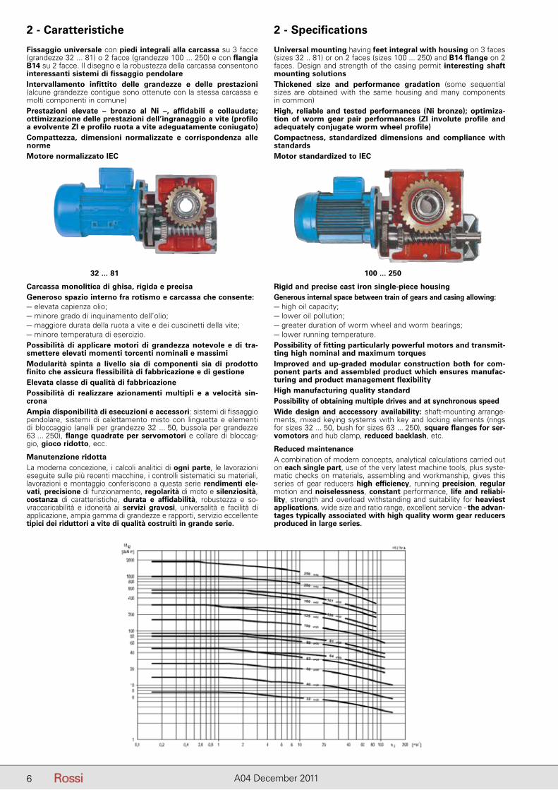
Universal mounting having feet integral with housing on 3 faces (sizes 32 .. 81) or on 2 faces (sizes 100 ... 250) and B14 flange on 2 faces. Design and strength of the casing permit interesting shaft mounting solutionsThickened size and performance gradation (some sequential sizes are obtained with the same housing and many components in common)High, reliable and tested performances (Ni bronze); optimiza-tion of worm gear pair performances (ZI involute profile and adequately conjugate worm wheel profile)Compactness, standardized dimensions and compliance with standardsMotor standardized to IEC
Fissaggio universale con piedi integrali alla carcassa su 3 facce (grandezze 32 ... 81) o 2 facce (grandezze 100 ... 250) e con flangia B14 su 2 facce. Il disegno e la robustezza della carcassa consentono interessanti sistemi di fissaggio pendolareIntervallamento infittito delle grandezze e delle prestazioni (alcune grandezze contigue sono ottenute con la stessa carcassa e molti componenti in comune)Prestazioni elevate – bronzo al Ni –, affidabili e collaudate; ottimizzazione delle prestazioni dell’ingranaggio a vite (profilo a evolvente ZI e profilo ruota a vite adeguatamente coniugato)Compattezza, dimensioni normalizzate e corrispondenza alle normeMotore normalizzato IEC
Carcassa monolitica di ghisa, rigida e precisaGeneroso spazio interno fra rotismo e carcassa che consente:– elevata capienza olio;– minore grado di inquinamento dell’olio;– maggiore durata della ruota a vite e dei cuscinetti della vite;– minore temperatura di esercizio.Possibilità di applicare motori di grandezza notevole e di tra-smettere elevati momenti torcenti nominali e massimiModularità spinta a livello sia di componenti sia di prodotto finito che assicura flessibilità di fabbricazione e di gestioneElevata classe di qualità di fabbricazionePossibilità di realizzare azionamenti multipli e a velocità sin-cronaAmpia disponibilità di esecuzioni e accessori: sistemi di fissaggio pendolare, sistemi di calettamento misto con linguetta e elementi di bloccaggio (anelli per grandezze 32 ... 50, bussola per grandezze 63 ... 250), flange quadrate per servomotori e collare di bloccag-gio, gioco ridotto, ecc.
Manutenzione ridottaLa moderna concezione, i calcoli analitici di ogni parte, le lavorazioni eseguite sulle più recenti macchine, i controlli sistematici su materiali, lavorazioni e montaggio conferiscono a questa serie rendimenti ele-vati, precisione di funzionamento, regolarità di moto e silenziosità, costanza di caratteristiche, durata e affidabilità, robustezza e so-vraccaricabilità e idoneità ai servizi gravosi, universalità e facilità di applicazione, ampia gamma di grandezze e rapporti, servizio eccellente tipici dei riduttori a vite di qualità costruiti in grande serie.
Rigid and precise cast iron single-piece housingGenerous internal space between train of gears and casing allowing:– high oil capacity;– lower oil pollution;– greater duration of worm wheel and worm bearings;– lower running temperature.Possibility of fitting particularly powerful motors and transmit-ting high nominal and maximum torquesImproved and up-graded modular construction both for com-ponent parts and assembled product which ensures manufac-turing and product management flexibilityHigh manufacturing quality standardPossibility of obtaining multiple drives and at synchronous speedWide design and acccessory availability: shaft-mounting arrange-ments, mixed keying systems with key and locking elements (rings for sizes 32 ... 50, bush for sizes 63 ... 250), square flanges for ser-vomotors and hub clamp, reduced backlash, etc.
Reduced maintenanceA combination of modern concepts, analytical calculations carried out on each single part, use of the very latest machine tools, plus syste-matic checks on materials, assembling and workmanship, gives this series of gear reducers high efficiency, running precision, regular motion and noiselessness, constant performance, life and reliabi-lity, strength and overload withstanding and suitability for heaviest applications, wide size and ratio range, excellent service - the advan-tages typically associated with high quality worm gear reducers produced in large series.
32 ... 81 100 ... 250
7A04 December 2011
2 - Caratteristiche 2 - Specifications
a - Gear reducerStructural featuresMain specifications are:– universal mounting having feet integral with housing (lower,
upper feet and vertical on the face opposite to motor for sizes 32 ... 81; lower and upper feet for sizes 100 ... 250) and B14 flange (integral with housing for sizes 32 ... 50) on 2 faces of hollow low speed shaft output. B5 flange with spigot «recess» which can be mounted onto B14 flanges (see chap. 17). Design and strength of the housing permit interesting shaft mounting solutions;
– intervallamento infittito delle grandezze (10 grandezze di cui 4 dop-pie con interasse finale 32 ... 250) e delle prestazioni; le grandezze doppie sono ottenute con la stessa carcassa e molti componenti in comune;
– struttura del riduttore dimensionata in modo da portare – sia per MR V, sia per MR IV – motori di grandezza notevole e da trasmet-tere gli elevati momenti torcenti nominali e massimi che l’ingra-naggio a vite consente alle basse velocità uscita;
– motoriduttori grandezze 40 ... 126 con prerotismo formato da 2 in-granaggi cilindrici coassiali per ottenere elevati rapporti di trasmis-sione – reversibili e non – con motore normalizzato (63 ... 112) in modo compatto ed economico;
– normalmente i motoriduttori MR V grandezze 32, 40 (con grandez-ze motore 63 e 71), 50 (con grandezze motore 71 e 80) e 63 ... 81 (con grandezze motore 80 e 90) hanno la flangia motore integrale con la carcassa;
– albero lento cavo con cava linguetta e (grandezze 63 ... 250) gole anello elastico per estrazione: di ghisa sferoidale (grigia per gran-dezze 32 e 40) integrale con la ruota a vite (grandezze 32 ... 161) o di acciaio (grandezze 200 e 250); albero lento normale (sporgente a destra o a sinistra) o bisporgente (ved. cap. 17);
– riduttori: lato entrata con piano (R V) o flangia (R IV) lavorati e con fori; estremità di vite con linguetta; estremità di vite ridotta (è la stessa estremità di vite utilizzata per R IV, MR IV, MR 2IV, MR V 160 ... 250 con giunto) con gola anello elastico;
– motoriduttori: motore normalizzato IEC calettato direttamente nella vite (MR V); per grandezze motore 200 ... 250 sistema di calettamento brevettato per facilitare montaggio e smontaggio ed evitare l’ossidazione di contatto; motore normalizzato con il pigno-ne montato direttamente sull’estremità d’albero (MR IV, MR 2IV);
– ventilazione forzata (grandezze 100 ... 250); realizzata in modo da disporre, con semplice asportazione del disco centrale del copriventola, della vite bisporgente; per MR V 81 con motore 100 e 112, ventola incorporata nella flangia attacco motore;
– cuscinetti volventi vite: obliquo a due corone di sfere più uno a sfe-re (grandezza 32); a rulli conici contrapposti (grandezze 40 ... 161); a rulli conici accoppiati più uno a sfere (grandezze 200 e 250);
– cuscinetti volventi ruota a vite: a sfere (grandezze 32 ... 160); a rulli conici (grandezze 161 ... 250);
– carcassa monolitica di ghisa 200 UNI ISO 185 con nervature trasversali di irrigidimento ed elevata capienza d’olio;
– lubrificazione a bagno d’olio con olio sintetico (cap. 16) per lubrifi-cazione «lunga vita»: riduttori con un tappo (grandezze 32 ... 64) o due tappi (grandezze 80 e 81) forniti completi di olio; con tappo di carico con valvola, scarico e livello (grandezze 100 ... 250) forniti senza olio; tenuta stagna;
– verniciatura: protezione esterna con vernice a polveri epossidiche (gran-dezze 32 ... 81) o con vernice sintetica (grandezze 100 ... 250) idonee a resistere ai normali ambienti industriali e a consentire ulteriori finiture con vernici sintetiche; colore blu RAL 5010 DIN 1843; protezione inter-na con vernice a polveri epossidiche (grandezze 32 ... 81) o epossidica (grandezze 100 ... 250) idonee a resistere agli oli sintetici;
– possibilità di realizzare gruppi riduttori e motoriduttori ad elevato rapporto di trasmissione con diversi tipi di rotismo in funzione dell’ingombro, del rendimento e della velocità uscita richiesta.
– thickened size (10 sizes with 4 size pairs with final centre distance 32 ... 250) and performance gradation; the size pairs are obtained with the same housing and with many components in common;
– gear reducer structure sized so as to accept particularly powerful motors – both MR V and MR IV – and to permit the transmission of high nominal and maximum torques at low output speeds, this being the particular advantage of worm gear pairs;
– gearmotor sizes 40 ... 126 with 2 cylindrical coaxial gear pair first stage in order to obtain high – reversible and irreversible – tran-smission ratios with standardized motor (63 ... 112) in a compact and economy way;
– normally, gearmotors MR V sizes 32, 40 (with motor sizes 63 and 71) 50 (with motor sizes 71 and 80) and 63 ... 81 (with motor sizes 80 and 90) have motor flange integral with the housing;
– hollow low speed shaft with keyway, and (sizes 63 ... 250) with circlip groove for removal purposes: in spheroidal cast iron (grey cast iron for sizes 32 and 40) integral with wormwheel (sizes 32 ... 161) or steel (sizes 200 and 250); standard (left or right extension) or double extension low speed shaft (see ch. 17).
– gear reducers: input face with machined surface (R V) or flange (R IV) and with fixing holes: wormshaft end with key, and reduced wormshaft end with circlip groove (the same as for R IV, MR IV,MR 2IV, MR V 160 ... 250 with coupling);
– gearmotors: motor standardized to IEC directly keyed into the worm (MR V), for motor sizes 200 ... 250 patented keying system to obtain easier installing and removing and avoid fretting corrosion; standardized motor with pinion directly mounted onto the shaft end (MR IV, MR 2IV);
– fan cooling (sizes 100 ... 250); use of double extension worm-shaft simply obtained by removing the fan cowl centre disc; for MR V 81 with motor 100 and 112, fan incorporated in motor mounting flange;
– bearings on worm: double row angular contact ball bearing plus ball bearing (size 32); face-to-face taper roller bearings (sizes 40 ... 161); paired back-to-back taper roller bearings plus one ball bea-ring (sizes 200 and 250);
– bearings on wormwheel: ball bearings (sizes 32 ... 160); taper roller bearings (sizes 161 ... 250);
– 200 UNI ISO 185 cast iron single-piece housing with transverse stiffening ribs, and high oil capacity;
– oil bath lubrication with synthetic oil (ch. 16) for «long-life» lubrication: units provided with one plug (sizes 32 ... 64) or two plugs (sizes 80 and 81) supplied filled with oil; with filler plug with valve, drain plug and level plug (sizes 100 ... 250) supplied without oil; sealed;
– paint: external coating in epoxy powder paint (sizes 32 ... 81) or in synthetic paint (sizes 100 ... 250) appropriate for resistance to normal industrial environments and suitable for the application of further coats of synthetic paint; color blue RAL 5010 DIN 1843; internal protection in epoxy powder paint (sizes 32 ... 81) or in epoxy resin paint (sizes 100 ... 250) appropriate for resistance to synthetic oils;
– possibility of obtaining combined gear reducer and gearmotor units providing high transmission ratios with different train of gears depending on overall dimension, efficiency, and final output speed requirements.
* relativo a n1 = 1 400 min-1 e al rapporto di trasmissione indicato nel diagramma.1) H1 H0 altezza d’asse; D Ø estremità d’albero lento [mm]; MN2, M2 Grand. momento torcente
[daN m]; Fr2 carico radiale [daN].
* concerning n1 = 1 400 min-1 and transmission ratio stated in the scheme.1) H1 H0 shaft height; D Ø low speed shaft end [mm]: MN2, M2 Size torque [daN m]; Fr2 radial
load [daN].
a - RiduttoreParticolarità costruttiveLe principali caratteristiche sono:– fissaggio universale con piedi integrali alla carcassa (piedi in-
feriori, superiori e verticali sulla faccia opposta al motore per gran-dezze 32 ... 81; piedi inferiori e superiori per grandezze 100 ... 250) e con flangia B14 (integrale alla carcassa per grandezze 32 ... 50) sulle 2 facce di uscita dell’albero lento cavo. Flangia B5 con cen-traggio «foro» montabile sulle flange B14 (ved. cap. 17). Il disegno e la robustezza della carcassa consentono interessanti sistemi di fissaggio pendolare;
8 A04 December 2011
2 - Caratteristiche 2 - Specifications
Rotismo:– a vite; ad 1 ingranaggio cilindrico e vite; a 2 ingranaggi cilindrici e
vite (solo motoriduttore);– ingranaggi a vite con rapporti di trasmissione (i = 10 ... 63) interi e
uguali per le diverse grandezze; i = 7 per MR V 32 ... 81;– 10 grandezze di cui 4 doppie (normale e rinforzata) con interasse
riduzione finale secondo serie R 10 (32 ... 250) per un totale di 14 grandezze;
– rapporti di trasmissione nominali secondo serie R 10 (10 ... 315; fino a 16 000 nei gruppi);
– vite cilindrica di acciaio 16 CrNi4 o 20 MnCr5 UNI 7846-78 (se-condo la grandezza) cementata/temprata con profilo a evolvente (ZI) rettificato e superfinito;
– ruota a vite con profilo adeguatamente coniugato a quello della vite tramite ottimizzazione del creatore, con mozzo di ghisa sferoidale o grigia (secondo la grandezza) e corona di bronzo al Ni CuSn12Ni2-B (EN1982-98) con elevata purezza e tenore di fosforo controllato,
– ingranaggio cilindrico di acciaio 16CrNi4 UNI 7846-78 cementato/temprato con profilo rettificato, dentatura elicoidale;
– capacità di carico del rotismo calcolata a rottura e ad usura; verifica capacità termica.
Norme specifiche:– rapporti di trasmissione nominali e dimensioni principali secondo
numeri normali UNI 2016 (DIN 323-74, NF X 01.001, BS 2045-65, ISO 3-73);
– dentiera di riferimento secondo BS 721-83; profilo ad evolvente (ZI) secondo UNI 4760/4-77 (DIN 3975-76, ISO/R 1122/2°-69);
– altezze d’asse secondo UNI 2946-68 (DIN 747-67, NF E 01.051,BS 5186-75, ISO 496-73);
– flange di fissaggio B14 e B5 (quest’ultima con centraggio «foro») derivate da UNEL 13501-69 (DIN 42948-65, IEC 72.2);
– fori di fissaggio serie media secondo UNI 1728-83 (DIN 69-71, NFE 27.040, BS 4186-67, ISO/R 273);
– estremità d’albero cilindriche (lunghe o corte) secondo UNI ISO 775-88 (DIN 748, NF E 22.051, BS 4506-70, ISO/R775-88) con foro filettato in testa secondo UNI 9321 (DIN 332 BI. 2-70, NF E 22.056) escluso corrispondenza d-D;
– linguette UNI 6604-69 (DIN 6885 Bl. 1-68, NF E 27.656 e 22.175, BS 4235.1-72, ISO/R 773-69) eccetto per determinati casi di ac coppiamento motore/riduttore in cui sono ribassate;
– forme costruttive derivate da UNEL 05513-67 (DIN 42950-64, IEC 34.7);– capacità di carico e rendimento dell’ingranaggio a vite determinati in
base a BS 721-83 integrata con ISO/CD 14521.
b - Motore elettricoEsecuzione normale:– motore normalizzato IEC;– asincrono trifase, chiuso, ventilato esternamente, con rotore a
gabbia;– polarità unica, frequenza 50 Hz, tensione Δ 230 V Y 400 V ± 10%1) fino
alla grandezza 132, Δ 400 V ± 10% a partire dalla grandezza 160;– classe di rendimento IE2 secondo IEC 60034-30 (calcolo secondo
IEC 60034-2-1, grado di incertezza basso) escluse le potenze inferiori a 0,75 kW - che non rientrano nel campo di applicabilità della norma - e le potenze evidenziate nella tabella di pag. 11 che sono valide per servizio S3 70% (indicato in targa);
– protezione IP 55, classe isolamento F, sovratemperatura classe B1);1) Limiti massimo e minimo di alimentazione motore ± 5% e classe di sovratemperatura F per
motori 90LC, 112MC, 132MC.
Train of gears:– worm gear pair; 1 cylindrical gear pair plus worm; with 2 cylindrical
gear pairs plus worm gear pair (gearmotor only);– worm gear pairs, with whole-number transmission ratios (i =
10 ... 63) identical for the different sizes; i = 7 for MR V 32 ... 81;– 10 sizes having 4 sizes pairs (standard and strengthened) with final
reduction centre distance to R 10 series (32 ... 250) for a total of 14 sizes;
– nominal transmission ratios to R 10 series (10 ... 315; up to 16 000 for combined units);
– casehardened and hardened cylindrical worm in 16 CrNi4 or20 MnCr5 UNI 7846-78 steel (depending on size) with ground andsuperfinished involute profile (ZI);
– wormwheel with profile especially conjugate to the worm through hob optimization, with hub in spheroidal or grey cast iron (depen-ding on size) and Ni bronze CuSn12Ni2-B (EN1982-98) gear rim with high pureness and controlled phosphor contents;
– casehardened and hardened cylindrical gear pair in 16CrNi4 UNI 7846-78 steel with ground profile and helical toothing;
– train of gear load capacity calculated for breakage and wear; ther-mal capacity verified.
Specific standards:– nominal transmission ratios and principal dimensions according to
UNI 2016 standard numbers (DIN 323-74, NF X 01.001, BS 2045-65,ISO 3-73);
– basic rack to BS 721-83; involute profile (ZI) to UNI 4760/4-77 (DIN 3975-76), ISO/R 1122/2-69);
– shaft heights to UNI 2946-68 (DIN 747-67, NF E 01.051, BS 5186-75, ISO 496-73);
– fixing flanges B14 and B5 (the latter with spigot «recess») taken from UNIL 13501-69 (DIN 42948-65, IEC 72.2);
– medium series fixing holes to UNI 1728-83 (DIN 69-71, NF E 27.040, BS 4186-67, ISO/R 273);
– cylindrical shaft ends (long or short) to UNI ISO 775-88 (DIN 748, NF E 22.051, BS 4506-70, ISO/R775/88) with tapped butt-end hole to UNI 9321 (DIN 332 BI. 2-70, NF E 22.056) excluding d-D diameter ratio;
– parallel keys to UNI 6604-69 (DIN 6885 Bl. 1-68, NF E 27.656 and 22.175, BS 4235.1-72, ISO/R 773-69) except for specific cases of motor-to-gear reducer coupling where key height is reduced;
– mounting positions taken from UNEL 05513-67 (DIN 42950-64, IEC 34;7);– worm gear pair load capacity and efficiency to BS 721-83 inte-
grated with ISO/CD 14521.
b - Electric motorStandard design:– motor standardized to IEC;– asynchronous three-phase, totally-enclosed, externally ventilated,
with cage rotor;– single polarity, frequency 50 Hz, voltage Δ 230 V Y 400 V ± 10%1)
up to size 132, Δ 400 V ± 10% from size 160 upwards;– IE2 efficiency class according to IEC 60034-30 (calculation to IEC 60034-
2-1, low uncertainty degree) excluded powers lower than 0,75 kW - which are out of IEC 60034-30 class range - and powers highlighted at page 11 which are valid for intermittent duty S3 70% (stated on the name plate);
– IP 55 protection, insulation class F, temperature rise class B1);1) Max and min limits of motor supply ± 5% and temperature rise class F for 90LC, 112MC,
132MC.
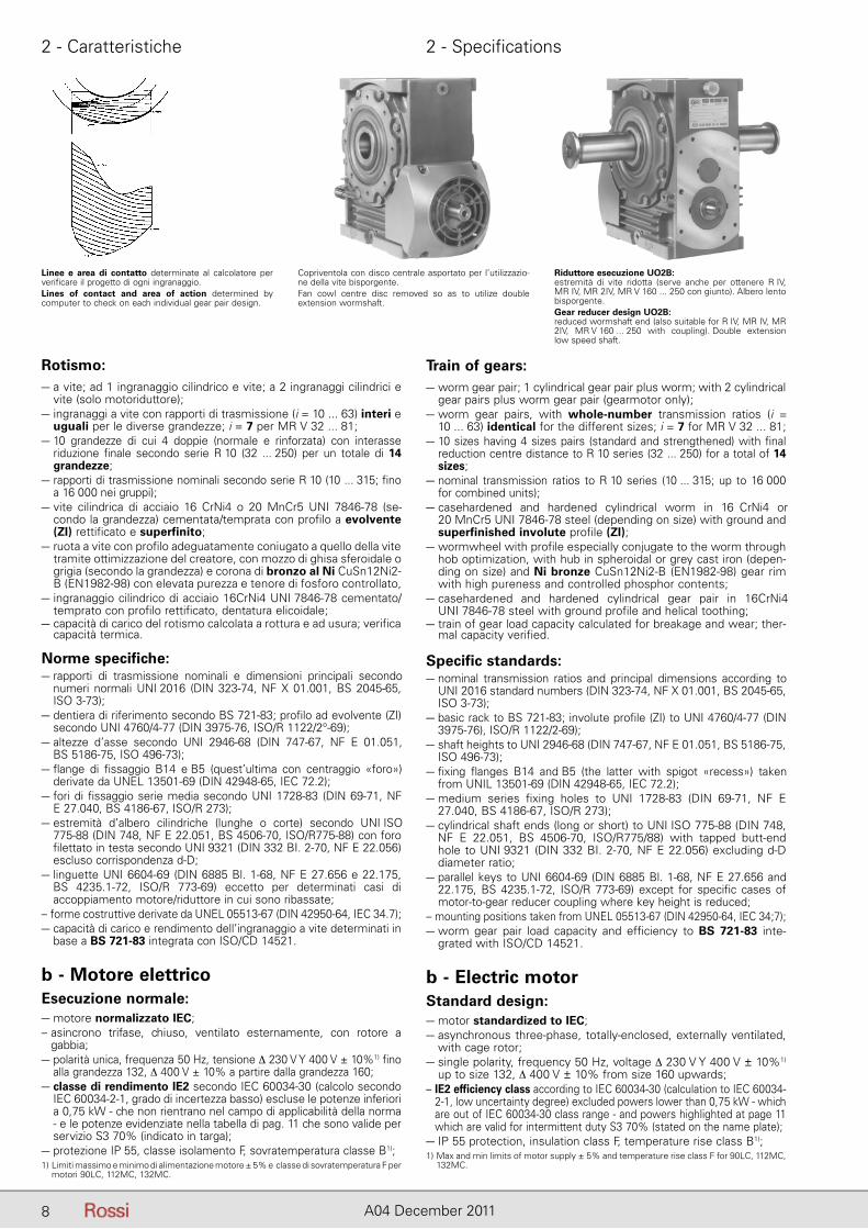
Linee e area di contatto determinate al calcolatore per verificare il progetto di ogni ingranaggio.Lines of contact and area of action determined bycomputer to check on each individual gear pair design.
Copriventola con disco centrale asportato per l’utilizzazio-ne della vite bisporgente.Fan cowl centre disc removed so as to utilize double extension wormshaft.
Riduttore esecuzione UO2B:estremità di vite ridotta (serve anche per ottenere R IV,MR IV, MR 2IV, MR V 160 ... 250 con giunto). Albero lento bisporgente.Gear reducer design UO2B:reduced wormshaft end (also suitable for R IV, MR IV, MR 2IV, MR V 160 ... 250 with coupling). Double extension low speed shaft.
9A04 December 2011
2 - Caratteristiche 2 - Specifications
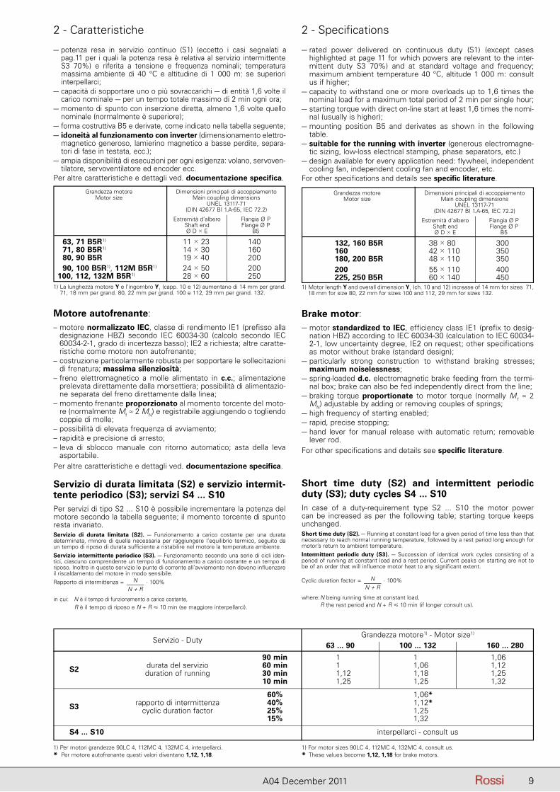
– potenza resa in servizio continuo (S1) (eccetto i casi segnalati a pag.11 per i quali la potenza resa è relativa al servizio intermittente S3 70%) e riferita a tensione e frequenza nominali; temperatura massima ambiente di 40 °C e altitudine di 1 000 m: se superiori interpellarci;
– capacità di sopportare uno o più sovraccarichi – di entità 1,6 volte il carico nominale – per un tempo totale massimo di 2 min ogni ora;
– momento di spunto con inserzione diretta, almeno 1,6 volte quello nominale (normalmente è superiore);
– forma costruttiva B5 e derivate, come indicato nella tabella se guente;– idoneità al funzionamento con inverter (dimensionamento elettro-
magnetico generoso, lamierino magnetico a basse perdite, separa-tori di fase in testata, ecc.);
– ampia disponibilità di esecuzioni per ogni esigenza: volano, servoven-tilatore, servoventilatore ed encoder ecc.
Per altre caratteristiche e dettagli ved. documentazione specifica.
1) La lunghezza motore Y e l’ingombro Y1 (capp. 10 e 12) aumentano di 14 mm per grand. 71, 18 mm per grand. 80, 22 mm per grand. 100 e 112, 29 mm per grand. 132.
Grandezza motore Dimensioni principali di accoppiamento Motor size Main coupling dimensions UNEL 13117-71 (DIN 42677 BI 1.A-65, IEC 72.2)
Estremità d’albero Flangia Ø P Shaft end Flange Ø P Ø D � E B5
63, 71 B5R1) 11 � 230 140 71, 80 B5R1) 14 � 300 160 80, 90 B5R 19 � 400 200 90, 100 B5R1), 112M B5R1) 24 � 500 200 100, 112, 132M B5R1) 28 � 600 250
Motore autofrenante:– motore normalizzato IEC, classe di rendimento IE1 (prefisso alla
designazione HBZ) secondo IEC 60034-30 (calcolo secondo IEC 60034-2-1, grado di incertezza basso); IE2 a richiesta; altre caratte-ristiche come motore non autofrenante;
– costruzione particolarmente robusta per sopportare le sollecitazioni di frenatura; massima silenziosità;
– freno elettromagnetico a molle alimentato in c.c.; alimentazione prelevata direttamente dalla morsettiera; possibilità di alimentazio-ne separata del freno direttamente dalla linea;
– momento frenante proporzionato al momento torcente del mo to-re (normalmente Mf ≈ 2 MN) e registrabile aggiungendo o to glien do coppie di molle;
– possibilità di elevata frequenza di avviamento;– rapidità e precisione di arresto;– leva di sblocco manuale con ritorno automatico; asta della leva
asportabile.Per altre caratteristiche e dettagli ved. documentazione specifica.
Servizio di durata limitata (S2) e servizio intermit-tente periodico (S3); servizi S4 ... S10Per servizi di tipo S2 ... S10 è possibile incrementare la potenza del motore secondo la tabella seguente; il momento torcente di spunto resta invariato.Servizio di durata limitata (S2). – Funzionamento a carico costante per una durata determinata, minore di quella necessaria per raggiungere l’equilibrio termico, seguito da un tempo di riposo di durata sufficiente a ristabilire nel motore la temperatura ambiente.Servizio intermittente periodico (S3). – Funzionamento secondo una serie di cicli iden-tici, ciascuno comprendente un tempo di funzionamento a carico costante e un tempo di riposo. Inoltre in questo servizio le punte di corrente all’avviamento non devono influenzare il riscaldamento del motore in modo sensibile.Rapporto di intermittenza = N
N + R · 100%
in cui: N è il tempo di funzionamento a carico costante, R è il tempo di riposo e N + R � 10 min (se maggiore interpellarci).
– rated power delivered on continuous duty (S1) (except cases highlighted at page 11 for which powers are relevant to the inter-mittent duty S3 70%) and at standard voltage and frequency; maximum ambient temperature 40 °C, altitude 1 000 m: consult us if higher;
– capacity to withstand one or more overloads up to 1,6 times the nominal load for a maximum total period of 2 min per single hour;
– starting torque with direct on-line start at least 1,6 times the nomi-nal (usually is higher);
– mounting position B5 and derivates as shown in the following table.
– suitable for the running with inverter (generous electromagne-tic sizing, low-loss electrical stamping, phase separators, etc.)
– design available for every application need: flywheel, independent cooling fan, independent cooling fan and encoder, etc.
For other specifications and details see specific literature.
1) Motor length Y and overall dimension Y1 (ch. 10 and 12) increase of 14 mm for sizes 71, 18 mm for size 80, 22 mm for sizes 100 and 112, 29 mm for sizes 132.
Grandezza motore Dimensioni principali di accoppiamento Motor size Main coupling dimensions UNEL 13117-71 (DIN 42677 BI 1.A-65, IEC 72.2)
Estremità d’albero Flangia Ø P Shaft end Flange Ø P Ø D � E B5
132, 160 B5R 38 � 8000 300 160 42 � 1100 350 180, 200 B5R 48 � 1100 350 200 55 � 1100 400 225, 250 B5R 60 � 1400 450
Brake motor:– motor standardized to IEC, efficiency class IE1 (prefix to desig-
nation HBZ) according to IEC 60034-30 (calculation to IEC 60034-2-1, low uncertainty degree, IE2 on request; other specifications as motor without brake (standard design);
– particularly strong construction to withstand braking stresses; maximum noiselessness;
– spring-loaded d.c. electromagnetic brake feeding from the termi-nal box; brake can also be fed independently direct from the line;
– braking torque proportionate to motor torque (normally M f ≈ 2 MN) adjustable by adding or removing couples of springs;
– high frequency of starting enabled;– rapid, precise stopping;– hand lever for manual release with automatic return; removable
lever rod.For other specifications and details see specific literature.
Short time duty (S2) and intermittent periodic duty (S3); duty cycles S4 ... S10In case of a duty-requirement type S2 ... S10 the motor power can be increased as per the following table; starting torque keeps unchanged.Short time duty (S2). – Running at constant load for a given period of time less than that necessary to reach normal running temperature, followed by a rest period long enough for motor’s return to ambient temperature.Intermittent periodic duty (S3). – Succession of identical work cycles consisting of a period of running at constant load and a rest period. Current peaks on starting are not to be of an order that will influence motor heat to any significant extent.
Cyclic duration factor = NN + R
· 100%
where: N being running time at constant load, R the rest period and N + R � 10 min (if longer consult us).
Servizio - DutyGrandezza motore1) - Motor size1)
63 ... 90 100 ... 132 160 ... 280
90 min 1 1 1,06 durata del servizio 60 min 1 1,06 1,12 S2 duration of running 30 min 1,12 1,18 1,25 10 min 1,25 1,25 1,32
60% 1,06* rapporto di intermittenza 40% 1,12* S3 cyclic duration factor 25% 1,25 15% 1,32
S4 ... S10 interpellarci - consult us
1) Per motori grandezze 90LC 4, 112MC 4, 132MC 4, interpellarci.* Per motore autofrenante questi valori diventano 1,12, 1,18.
1) For motor sizes 90LC 4, 112MC 4, 132MC 4, consult us.* These values become 1,12, 1,18 for brake motors.
10 A04 December 2011
2 - Caratteristiche 2 - Specifications
z � 0,63 · z0 · J0
J0 + J · [1 – � PP1
�2 · 0,6]
In caso di motore non autofrenante la potenza nominale è riferita al servizio intermittente S3 70% (anche in targa).
1) Velocità motore in base alle quali sono state calcolate le velocità motoriduttore n2.2) I valori di momento d’inerzia J0 e di momento frenante Mf sono validi solo per motore
autofrenante (grand. � 200L).3) Per grand. � 132, i valori di Mspunto / MN e di frequenza di avviamento a vuoto z0 [avv./h]
sono validi solo per motore autofrenante.4) Normalmente il motore viene fornito tarato ad un momento frenante inferiore (ved.
documentazione specifica).5) Per 2 poli 4 daN m.* Potenza o corrispondenza potenza-grandezza motore non normalizzate.
In case of motor without brake the nominal power is referred to the intermittent duty S3 70% (on the name plate too).
1) Motor speed on the basis of which the gearmotor speeds n2 have been calculated.2) Moment of inertia values J0, braking torque values Mf are valid for brake motor (size
� 200L), only.3) For size � 132, Mstart / MN values and no load starting frequency z0 [start./h] values are
valid for brake motor, only.4) Motor is usually supplied with lower braking torque setting (see specific literature).5) For 2 pole 4 daN m.* Power or motor power-to-size correspondence not according to standard.
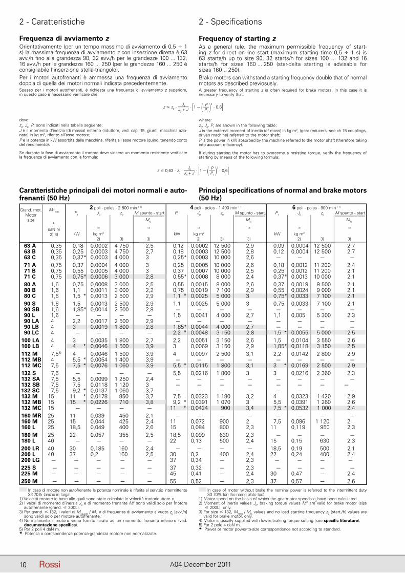
Caratteristiche principali dei motori normali e auto- frenanti (50 Hz)
Principal specifications of normal and brake motors (50 Hz)
M fmax
≈daN m2) 4)
Grand. mot.Motorsize
2 poli - poles - 2 800 min-1 1)
P1 J0 z0 M spunto - start. . MN
≈ ≈ kW kg m2 2) 3) 3)
4 poli - poles - 1 400 min-1 1)
P1 J0 z0 M spunto - start. . MN
≈ ≈ kW kg m2 2) 3) 3)
6 poli - poles - 900 min-1 1)
P1 J0 z0 M spunto - start. . MN
≈ ≈ kW kg m2 2) 3) 3)
63 A 0,35 0,18 0,0002 4 750 2,5 0,12 0,0002 12 500 2,9 0,09 0,0004 12 500 2,7 63 B 0,35 0,25 0,0003 4 750 2,7 0,18 0,0003 12 500 2,8 0,12 0,0004 12 500 2,7 63 C 0,35 0,37* 0,0003 4 000 3,0 0,25* 0,0003 10 000 2,6 0– ,0– – 0– 71 A 0,75 0,37 0,0004 4 000 3,1 0,25 0,0005 10 000 2,6 0,18 0,0012 11 200 2,4 71 B 0,75 0,55 0,0005 4 000 3,1 0,37 0,0007 10 000 2,5 0,25 0,0012 11 200 2,1 71 C 0,75 0,75* 0,0006 3 000 2,8 0,55* 0,0008 8 000 2,4 0,37* 0,0013 10 000 2,1 80 A 1,6 0,75 0,0008 3 000 2,5 0,55 0,0015 8 000 2,6 0,37 0,0019 9 500 2,1 80 B 1,6 1,1 0,0011 3 000 2,2 0,75 0,0019 7 100 2,9 0,55 0,0024 9 000 2,1 80 C 1,6 1,5 * 0,0013 2 500 2,9 1,1 * 0,0025 5 000 3,0 0,75* 0,0033 7 100 2,1 90 S 1,6 1,5 0,0013 2 500 2,9 1,1 0,0025 5 000 3,0 0,75 0,0033 7 100 2,1 90 SB 1,6 1,85* 0,0014 2 500 2,8 0– 0 – – – 0– ,0– – 0– 90 L 1,6 0– 0 – – – 1,5 0,0041 4 000 2,7 1,1 0,005 5 300 2,3 90 LA 4 2,2 0,0017 2 500 2,9 0– 0 – – – 0– ,0– – 0– 90 LB 4 3 00,0019 1 800 2,8 1,85* 0,0044 4 000 2,7 0– ,0– – 0– 90 LC 4 0– 0 – – – 2,2 * 0,0048 3 150 2,8,0 1,5 * 0,0055 5 000 2,5 100 LA 4 3 0,0035 1 800 2,7 2,2 0,0051 3 150 2,6 01,5 0,0104 3 550 2,6 100 LB 4 4 * 0,0046 1 500 3,9 3 0,0069 3 150 2,9 1,85* 0,0118 3 150 2,5 112 M 7,55) 4 0,0046 1 500 3,9 4 0,0097 2 500 3,1 2,2 0,0142 2 800 2,9 112 MB 4 5,5 * 0,0054 1 400 3,9 0– 0 – – – 0– ,0– – 0– 112 MC 7,5 7,5 * 0,0076 1 060 3,9 5,5 * 0,0115 1 800 3,1 3 * 0,0169 2 500 2,9 132 S 7,5 0– 0 – – – 5,5 0,0216 1 800 3,0 3 0,0216 2 360 2,3 132 SA 7,5 5,5 0,0099 1 250 2,4 0– 0 – – – 0– ,0– – 0– 132 SB 7,5 7,5 0,0118 1 120 3,0 0– 0 – – – 0– ,0– – 0–0 132 SC 7,5 9,2 * 0,0137 1 060 3,7 0– 0 – – – 0– ,0– – 0– 132 M 15 11 * 0,0178 850 3,7 7,5 0,0323 1 180 3,2 4 0,0323 1 420 2,9 132 MB 15 15 * 0,0226 710 3,8 9,2 * 0,0391 1 070 3,0 5,5 0,0391 1 260 2,6 132 MC 15 0– 0 – – – 11 * 0,0424 900 3,4 7,5 * 0,0532 1 000 2,4 160 MR 25 11 0,039 450 2,1 0– 0 – – – 0– ,0– – 0– 160 M 25 15 0,044 425 2,4 11 00,072 900 2,3 7,5 0,096 1 120 2 160 L 25 18,5 00,049 400 2,6 15 0,084 800 2,3 11 0,119 950 2,3 180 M 25 22 0,057 355 2,5 18,5 0,099 630 2,3 0– ,0– – 0– 180 L 40 0– 0 – – – 22 0,13 500 2,4 15 0,15 630 2,3 200 LR 40 30 0,185 160 2,4 0– 0 – – – 18,5 0,19 500 2,1 200 L 40 37 0,2 160 2,5 30 0,2 400 2,4 22 0,24 400 2,4 200 LG – – – – – 37 0,34 – 2,3 – – – – 225 S 0– ,0– – 0– – 37 0,32 – 2,3 0– ,0– – 0– 225 M 0– ,0– – 0– – 45 0,41 – 2,4 30 0,47 – 2,4 250 M 0– ,0– – 0– – 55 0,52 – 2,3 37 0,57 – 2,6
Frequenza di avviamento zOrientativamente (per un tempo massimo di avviamento di 0,5 � 1 s) la massima frequenza di avviamento z con inserzione diretta è 63 avv./h fino alla grandezza 90, 32 avv./h per le grandezze 100 ... 132, 16 avv./h per le grandezze 160 ... 250 (per le grandezze 160 ... 250 è consigliabile l’inserzione stella-triangolo).Per i motori autofrenanti è ammessa una frequenza di avviamento doppia di quella dei motori normali indicata precedentemente.Spesso per i motori autofrenanti, è richiesta una frequenza di avviamento z superiore,in questo caso è necessario verificare che:
dove:z0, J0, P1 sono indicati nella tabella seguente;J è il momento d’inerzia (di massa) esterno (riduttore, ved. cap. 15, giunti, macchina azio-nata) in kg m2, riferito all’asse motore;P è la potenza in kW assorbita dalla macchina, riferita all’asse motore (quindi tenendo conto del rendimento).
Se durante la fase di avviamento il motore deve vincere un momento resistente verificare la frequenza di avviamento con la formula:
Frequency of starting zAs a general rule, the maximum permissible frequency of start-ing z for direct on-line start (maximum starting time 0,5 � 1 s) is 63 starts/h up to size 90, 32 starts/h for sizes 100 ... 132 and 16starts/h for sizes 160 ... 250 (star-delta starting is advisable forsizes 160 .. 250).Brake motors can withstand a starting frequency double that of normal motors as described previosusly.A greater frequency of starting z is often required for brake motors. In this case it isnecessary to verify that:
where:z0, J0, P1 are shown in the following table;J is the external moment of inertia (of mass) in kg m2, (gear reducers, see ch 15 couplings, driven machine) referred to the motor shaft;P is the power in kW absorbed by the machine referred to the motor shaft (therefore taking into account efficiency).
If during starting the motor has to overcome a resisting torque, verify the frequency of starting by means of the following formula:
z � z0 · J0
J0 + J · [1 – � PP1
�2 · 0,6]
11A04 December 2011
2 - Caratteristiche 2 - Specifications
Specific standards:– nominal powers and dimensions to CENELEC HD 231 (IEC 72-1,
CNR-CEI UNEL 13117-71 and 13118-71, DIN 42677, NF C51-120, BS 5000-10 and BS 4999-141) for mounting positions IM B5, IM B14 and derivates;
– nominal performances and running specifications to CENELEC EN 60034-1 (IEC 34-1, CEI EN 60034-1, DIN VDE 0530-1, NF C51-111, BS EN 60034-1);
– protection to CENELEC EN 60034-5 (IEC 34-5, CEI 2-16, DIN EN 60034-5, NF C51-115, BS 4999-105);
– mounting positions to CENELEC EN 60034-7 (IEC 34-7, CEI EN 60034-7, DIN IEC 34-7, NF C51-117, BS EN 60034-7);
– balancing and vibration velocity (vibration under standard rating N) to CENELEC HD 53.14 S1 (CEI IEC 34-14, ISO 2373 CEI 2-23, BS 4999-142); motors are balanced with half key inserted into shaft extension;
– cooling to CENELEC EN 60034-6 (CEI 2-7, IEC 34-6): standard type IC 411; type IC 416 for non-standard design with axial independ-ent cooling fan.
Frequenza 60 HzI motori normali fino alla grandezza 132 avvolti a 50 Hz possono es sere alimentati a 60 Hz: la velocità aumenta del 20%. Se la tensio-ne di alimentazione corrisponde a quella di avvolgimento la potenza non varia, purché si accettino sovratemperature superiori, e la richie-sta di potenza stessa non sia esasperata, mentre il momento di spun-to e massimo diminuiscono del 17%. Se la tensione di alimentazione è maggiore di quella di avvolgimento del 20%, la potenza aumenta del 20%, mentre il momento di spunto e massimo non variano.Per motori autofrenanti ved. documentazione specifica.A partire dalla grandezza 160 è bene che i motori – normali e auto-frenanti – siano avvolti espressamente a 60 Hz, anche per sfruttare la possibilità dell’aumento di potenza del 20%.
Frequency 60 HzNormal motors up to size 132 wound for 50 Hz can be fed at 60 Hz; in this case speed increases by 20%. If input-voltage corresponds to winding voltage, power remains unchanged, providing that higher temperature rise values are acceptable, and that the power require-ment is not unduly demanding, whilst starting and maximum torques decrease by 17%. If input-voltage is 20% higher than winding volt-age, power increases by 20% whilst starting and maximum torques keep unchanged.For brake motors see specific literature.From size 160 upwards motors – both standard and brake ones – should be would for 60 Hz exploiting the 20% power increase as a matter of course.
Norme specifiche:– potenze nominali e dimensioni secondo CENELEC HD 231 (IEC
72-1, CNR-CEI UNEL 13117-71 e 13118-71, DIN 42677, NF C51-120, BS 5000-10 e BS 4999-141) per forma costruttiva IM B5, IM B14 e derivate;
– caratteristiche nominali e di funzionamento secondo CENELEC EN 60034-1 (IEC 34-1, CEI EN 60034-1, DIN VDE 0530-1, NF C51-111, BS EN 60034-1);
– gradi di protezione secondo CENELEC EN 60034-5 (IEC 34-5, CEI 2-16, DIN EN 60034-5, NF C51-115, BS 4999-105);
– forme costruttive secondo CENELEC EN 60034-7 (IEC 34-7, CEI EN 60034-7, DIN IEC 34-7, NF C51-117, BS EN 60034-7);
– equilibratura e velocità di vibrazione (grado di vibrazione normale N) secondo CENELEC HD 53.14 S1 (CEI IEC 34-14, ISO 2373 CEI 2-23, BS 4999-142); i motori sono equilibrati con mezza linguetta nella sporgenza dell’albero;
– raffreddamento secondo CENELEC EN 60034-6 (CEI 2-7, IEC 34-6): tipo standard IC 411; tipo IC 416 per esecuzione speciale con ser-voventilatore assiale.
12 A04 December 2011
3 - Designazione 3 - Designation
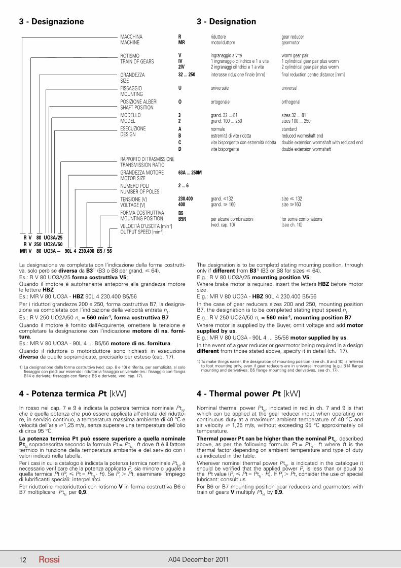
La designazione va completata con l’indicazione della forma costrutti-va, solo però se diversa da B31) (B3 o B8 per grand. � 64).Es.: R V 80 UO3A/25 forma costruttiva V5;Quando il motore è autofrenante anteporre alla grandezza motore le lettere HBZEs.: MR V 80 UO3A - HBZ 90L 4 230.400 B5/56Per i riduttori grandezze 200 e 250, forma costruttiva B7, la designa-zione va completata con l’indicazione della velocità entrata n1.Es.: R V 250 UO2A/50 n1 = 560 min-1, forma costruttiva B7Quando il motore è fornito dall’Acquirente, omettere la tensione e completare la designazione con l’indicazione motore di ns. forni-tura.Es.: MR V 80 UO3A - 90L 4 ... B5/56 motore di ns. fornitura.Quando il riduttore o motoriduttore sono richiesti in esecuzione di versa da quelle sopraindicate, precisarlo per esteso (cap. 17).
1) La designazione della forma costruttiva (ved. cap. 8 e 10) è riferita, per semplicità, al solo fissaggio con piedi pur essendo i riduttori a fissaggio universale (es.: fissaggio con flangia B14 e derivate; fissaggio con flangia B5 e derivate, ved. cap. 17).
4 - Potenza termica Pt [kW]
In rosso nei cap. 7 e 9 è indicata la potenza termica nominale PtN, che è quella potenza che può essere applicata all’entrata del ridutto-re, in servizio continuo, a temperatura massima ambiente di 40 °C e velocità dell’aria �1,25 m/s, senza superare una temperatura dell’olio di circa 95 °C.La potenza termica Pt può essere superiore a quella nominale PtN sopradescritta secondo la formula Pt = PtN · ft dove ft è il fattore termico in funzione della temperatura ambiente e del servizio con i valori indicati nella tabella.Per i casi in cui a catalogo è indicata la potenza termica nominale PtN, è necessario verificare che la potenza applicata P1 sia minore o uguale a quella termica Pt (P1 � Pt = PtN · ft). Se P1 � Pt, esaminare l’impiego di lubrificanti speciali: interpellarci.Per riduttori e motoriduttori con rotismo V in forma costruttiva B6 o B7 moltiplicare PtN per 0,9.
The designation is to be completd stating mounting position, through only if different from B31) (B3 or B8 for sizes � 64).E.g.: R V 80 UO3A/25 mounting position V5;Where brake motor is required, insert the letters HBZ before motor size.E.g.: MR V 80 UO3A - HBZ 90L 4 230.400 B5/56In the case of gear reducers sizes 200 and 250, mounting position B7, the designation is to be completed stating input speed n1.E.g.: R V 250 UO2A/50 n1 = 560 min-1, mounting position B7Where motor is supplied by the Buyer, omit voltage and add motor supplied by us.E.g.: MR V 80 UO3A - 90L 4 ... B5/56 motor supplied by us.In the event of a gear reducer or gearmotor being required in a design different from those stated above, specify it in detail (ch. 17).
1) To make things easier, the designation of mounting position (see ch. 8 and 10) is referred to foot mounting only, even if gear reducers are in universal mounting (e.g.: B14 flange mounting and derivatives; B5 flange mounting and derivatives, see ch. 17).
4 - Thermal power Pt [kW]
Nominal thermal power PtN, indicated in red in ch. 7 and 9 is that which can be applied at the gear reducer input when operating on continuous duty at a maximum ambient temperature of 40 °C and air velocity � 1,25 m/s, without exceeding 95 °C approximately oil temperature.Thermal power Pt can be higher than the nominal PtN, described above, as per the following formula: Pt = PtN · ft where ft is the thermal factor depending on ambient temperature and type of duty as indicated in the table.Wherever nominal thermal power PtN, is indicated in the catalogue it should be verified that the applied power P1 is less than or equal to the Pt value (P1 � Pt = PtN · ft). If P1 � Pt, consider the use of special lubricant: consult us.For B6 or B7 mounting position gear reducers and gearmotors with train of gears V multiply PtN by 0,9.
MACCHINAMACHINE
R riduttore gear reducerMR motoriduttore gearmotor
ROTISMOTRAIN OF GEARS
V ingranaggio a vite worm gear pairIV 1 ingranaggio cilindrico e 1 a vite 1 cylindrical gear pair plus worm2IV 2 ingranaggi cilindrici e 1 a vite 2 cylindrical gear pair plus worm
GRANDEZZASIZE
32 ... 250 interasse riduzione finale [mm] final reduction centre distance [mm]
FISSAGGIOMOUNTING
U universale universal
POSIZIONE ALBERISHAFT POSITION
O ortogonale orthogonal
MODELLO MODEL
3 grand. 32 ... 81 sizes 32 ... 812 grand. 100 ... 250 sizes 100 ... 250
ESECUZIONE DESIGN
A normale standardB estremità di vite ridotta reduced wormshaft endC vite bisporgente con estremità ridotta double extension wormshaft with reduced endD vite bisporgente double extension wormshaft
RAPPORTO DI TRASMISSIONE TRANSMISSION RATIO
GRANDEZZA MOTORE MOTOR SIZE
63A ... 250M
NUMERO POLI NUMBER OF POLES
2 ... 6
TENSIONE [V] VOLTAGE [V]
230.400 grand. �132 size � 132400 grand. � 160 size �160
FORMA COSTRUTTIVA MOUNTING POSITION
B5B5R per alcune combinazioni for some combinations (ved. cap. 10) (see ch. 10) VELOCITÀ D’USCITA [min-1]
OUTPUT SPEED [min-1] R V 80 U O 3 A /25 R V 250 U O 2 A /50 MR V 80 U O 3 A — 90L 4 230.400 B5 / 56
13A04 December 2011
4 - Potenza termica Pt [kW] 4 - Thermal power Pt [kW]
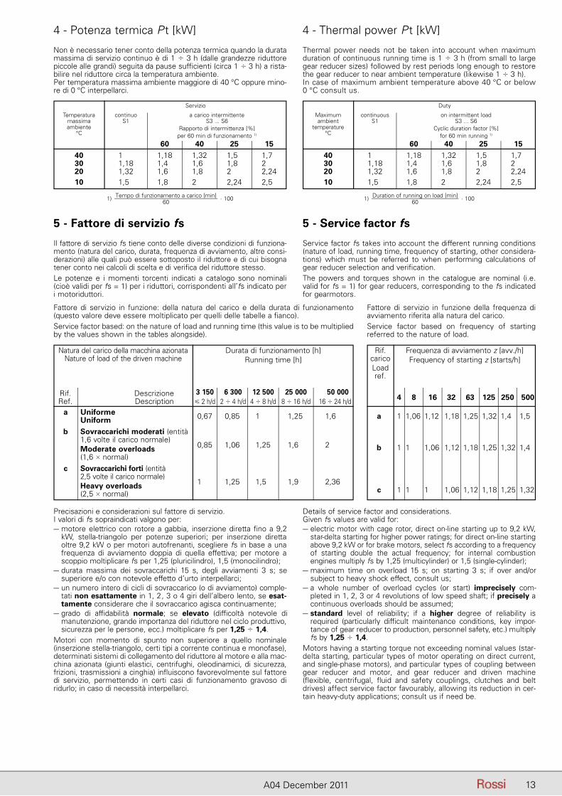
Non è necessario tener conto della potenza termica quando la durata massima di servizio continuo è di 1 � 3 h (dalle grandezze riduttore piccole alle grandi) seguita da pause sufficienti (circa 1 � 3 h) a rista-bilire nel riduttore circa la temperatura ambiente.Per temperatura massima ambiente maggiore di 40 °C oppure mino-re di 0 °C interpellarci.
Thermal power needs not be taken into account when maximum duration of continuous running time is 1 � 3 h (from small to large gear reducer sizes) followed by rest periods long enough to restore the gear reducer to near ambient temperature (likewise 1 � 3 h).In case of maximum ambient temperature above 40 °C or below 0 °C consult us.
Temperaturamassimaambiente
°C
continuoS1
a carico intermittenteS3 ... S6
Rapporto di intermittenza [%]per 60 min di funzionamento 1)
60 40 25 15
Servizio
40 1,00 1,18 1,32 1,50 1,70 30 1,18 1,40 1,60 1,80 2,00 20 1,32 1,60 1,80 2,00 2,24 10 1,50 1,80 2,00 2,24 2,50
Maximumambient
temperature°C
continuousS1
on intermittent loadS3 ... S6
Cyclic duration factor [%]for 60 min running 1)
60 40 25 15
Duty
40 1,00 1,18 1,32 1,50 1,70 30 1,18 1,40 1,60 1,80 2,00 20 1,32 1,60 1,80 2,00 2,24 10 1,50 1,80 2,00 2,24 2,50
1) Tempo di funzionamento a carico [min]60
· 100 1) Duration of running on load [min]60
· 100
5 - Fattore di servizio fs
Il fattore di servizio fs tiene conto delle diverse condizioni di funziona-mento (natura del carico, durata, frequenza di avviamento, altre consi-derazioni) alle quali può essere sottoposto il riduttore e di cui bisogna tener conto nei calcoli di scelta e di verifica del riduttore stesso.Le potenze e i momenti torcenti indicati a catalogo sono nominali (cioè validi per fs = 1) per i riduttori, corrispondenti all’fs indicato per i motoriduttori.
5 - Service factor fs
Service factor fs takes into account the different running conditions (nature of load, running time, frequency of starting, other considera-tions) which must be referred to when performing calculations of gear reducer selection and verification.The powers and torques shown in the catalogue are nominal (i.e. valid for fs = 1) for gear reducers, corresponding to the fs indicated for gearmotors.
Precisazioni e considerazioni sul fattore di servizio.I valori di fs sopraindicati valgono per:– motore elettrico con rotore a gabbia, inserzione diretta fino a 9,2
kW, stella-triangolo per potenze superiori; per inserzione diretta oltre 9,2 kW o per motori autofrenanti, scegliere fs in base a una frequenza di avviamento doppia di quella effettiva; per motore a scoppio moltiplicare fs per 1,25 (pluricilindro), 1,5 (monocilindro);
– durata massima dei sovraccarichi 15 s, degli avviamenti 3 s; se superiore e/o con notevole effetto d’urto interpellarci;
– un numero intero di cicli di sovraccarico (o di avviamento) comple-tati non esattamente in 1, 2, 3 o 4 giri dell’albero lento, se esat-tamente considerare che il sovraccarico agisca continuamente;
– grado di affidabilità normale; se elevato (difficoltà notevole di ma nutenzione, grande importanza del riduttore nel ciclo produttivo, sicurezza per le persone, ecc.) moltiplicare fs per 1,25 � 1,4.
Motori con momento di spunto non superiore a quello nominale (in serzione stella-triangolo, certi tipi a corrente continua e monofase), determinati sistemi di collegamento del riduttore al motore e alla mac-china azionata (giunti elastici, centrifughi, oleodinamici, di sicurezza, frizioni, trasmissioni a cinghia) influiscono favorevolmente sul fattore di servizio, permettendo in certi casi di funzionamento gravoso di ri durlo; in caso di necessità interpellarci.
Details of service factor and considerations.Given fs values are valid for:– electric motor with cage rotor, direct on-line starting up to 9,2 kW,
star-delta starting for higher power ratings; for direct on-line starting above 9,2 kW or for brake motors, select fs according to a frequency of starting double the actual frequency; for internal combustion engines multiply fs by 1,25 (multicylinder) or 1,5 (single-cylinder);
– maximum time on overload 15 s; on starting 3 s; if over and/or subject to heavy shock effect, consult us;
– a whole number of overload cycles (or start) imprecisely com-pleted in 1, 2, 3 or 4 revolutions of low speed shaft; if precisely a continuous overloads should be assumed;
– standard level of reliability; if a higher degree of reliability is re quired (particularly difficult maintenance conditions, key impor-t ance of gear reducer to production, personnel safety, etc.) multiply fs by 1,25 � 1,4.
Motors having a starting torque not exceeding nominal values (star-delta starting, particular types of motor operating on direct current, and single-phase motors), and particular types of coupling between gear reducer and motor, and gear reducer and driven machine(flexible, centrifugal, fluid and safety couplings, clutches and belt drives) affect service factor favourably, allowing its reduction in cer-tain heavy-duty applications; consult us if need be.
Fattore di servizio in funzione della frequenza di avviamento riferita alla natura del carico.Service factor based on frequency of starting referred to the nature of load.
Natura del carico della macchina azionataNature of load of the driven machine
Rif. Descrizione Ref. Description
Durata di funzionamento [h]Running time [h]
3 150 6 300 12 500 25 000 50 000 � 2 h/d 2 � 4 h/d 4 � 8 h/d 8 � 16 h/d 16 � 24 h/d
a UniformeUniform 0,67 0,85 1 1,25 1,6
b Sovraccarichi moderati (entità1,6 volte il carico normale)
0,85 1,06 1,25 1,6 2 Moderate overloads(1,6 � normal)
c Sovraccarichi forti (entità2,5 volte il carico normale)
1 1,25 1,5 1,9 2,36 Heavy overloads(2,5 � normal)
Rif.caricoLoadref.
Frequenza di avviamento z [avv./h]Frequency of starting z [starts/h]
4 8 16 32 63 125 250 500
a 1 1,06 1,12 1,18 1,25 1,32 1,4 1,5
b 1 1 1,06 1,12 1,18 1,25 1,32 1,4
c 1 1 1 1,06 1,12 1,18 1,25 1,32
Fattore di servizio in funzione: della natura del carico e della du rata di funzionamento (questo valore deve essere moltiplicato per quelli delle tabelle a fianco).Service factor based: on the nature of load and running time (this value is to be multiplied by the values shown in the tables alongside).
14 A04 December 2011
6 - Scelta 6 - Selection
a - Riduttore
Determinazione grandezza riduttore– Disporre dei dati necessari: potenza P2 richiesta all’uscita del
ri duttore, velocità angolari n2 e n1, condizioni di funzionamento (na tura del carico, durata, frequenza di avviamento z, altre consi-derazioni) riferendosi al cap. 5.
– Determinare il fattore di servizio fs in base alle condizioni di fun-zionamento (cap. 5).
– Scegliere la grandezza riduttore (contemporaneamente anche il rotismo e il rapporto di trasmissione i) in base a n2, n1 e ad una potenza PN2 uguale o maggiore a P2 · fs (cap. 7).
– Calcolare la potenza P1 richiesta all’entrata del riduttore con la
– formula P2� , dove � = PN2
PN1
è il rendimento del riduttore (cap.7).
Quando, per motivi di normalizzazione del motore, risulta (considera-to l’eventuale rendimento motore-riduttore) una potenza P1 applicata all’entrata del riduttore maggiore di quella richiesta, deve essere certo che la maggior potenza applicata non sarà mai richiesta e la frequenza di avviamento z sia talmente bassa da non influire sul fattore di servizio (cap. 5).Altrimenti per la scelta moltiplicare la PN2 per il rapporto P1 applicata
P1 richiesta.
I calcoli possono essere effettuati in base ai momenti torcenti, anziché alle potenze; anzi per bassi valori di n2 è preferibile.
Verifiche– Verificare gli eventuali carichi radiali Fr1, Fr2 e assiale Fa2 secondo le
istruzioni e i valori dei cap. 13 e 14.– Quando si dispone del diagramma di carico e/o si hanno sovrac-
carichi – dovuti ad avviamenti a pieno carico (specialmente per elevate inerzie e bassi rapporti di trasmissione), frenature, urti, casi di riduttori irreversibili o poco reversibili in cui la ruota a vite diventa motrice per effetto delle inerzie della macchina azionata, potenza applicata superiore a quella richiesta, altre cause statiche o dinamiche – verificare che il massimo picco di momento torcen-te (cap. 15) sia sempre inferiore M2max (cap. 7), se superiore o non valutabile installare – nei suddetti casi – dispositivi di sicurezza in modo da non superare mai M2max.
– Quando per il riduttore è indicata – in rosso nel cap. 7 – la potenza termica nominale P tN, verificare che P1 � P t (cap. 4).
Designazione per l’ordinazionePer l’ordinazione è necessario completare la designazione del ridut-tore come indicato nel cap. 3. Pertanto occorre precisare:esecuzione, forma costruttiva (solamente se diversa da B3, B3 o B8 per grand. � 64) (cap. 8); velocità entrata n1 per i riduttori gran-dezze 200 e 250 in forma costruttiva B7, solamente se maggiore di1 400 min-1 o minore di 355 min-1 per i rimanenti; eventuali accessori ed esecuzioni speciali (cap. 17).Es.: R V 80 UO3A/25 forma costruttiva V5 R V 250 UO2A/50 n1 = 560 min-1, forma costruttiva B7.
b - Motoriduttore
Determinazione grandezza motoriduttore– Disporre dei dati necessari: potenza P2 richiesta all’uscita del
mo-toriduttore, velocità angolare n2, condizioni di funzionamento (na-tura del carico, durata, frequenza di avviamento z, altre consi-derazioni), riferendosi al cap. 5.
– Determinare il fattore di servizio fs in base alle condizioni di funzio-namento (cap. 5).
– Scegliere la grandezza motoriduttore in base a n2, fs, P2 (cap. 9).Quando, per motivi di normalizzazione del motore, la potenza di-sponibile a catalogo P2 è molto maggiore di quella richiesta, il moto-riduttore può essere scelto in base a un fattore di servizio minore
(fs · P2 richiestaP2 disponibile
) solamente se è certo che la maggior potenza
disponibile non sarà mai richiesta e la frequenza di avviamento z è talmente bassa da non influire sul fattore di servizio (cap. 5).
I calcoli possono essere effettuati in base ai momenti torcenti, anzi-ché alle potenze; anzi, per bassi valori di n2 è preferibile.
Verifiche– Verificare l’eventuale carico radiale Fr2 e assiale Fa2 secondo le
istruzioni e i valori del cap. 14.– Verificare, per il motore, la frequenza di avviamento z quando è
su periore a quella normalmente ammessa, secondo le istruzioni e i valori del cap. 2b; normalmente questa verifica è richiesta solo per
a - Gear reducerDetermining the gear reducer size– Make available all necessary data: required output power P2 of
gear reducer, speeds n2 and n1, running conditions (nature of load, running time, frequency of starting z, other considerations) with reference to ch. 5.
– Determine service factor fs on the basis of running conditions (ch. 5).
– Select the gear reducer size (also, the train of gears and transmis-sion ratio i at the same time) on the basis of n2, n1 and of a power PN2 greater than or equal to P2 · fs (ch. 7).
– Calculate power P1 required at input side of gear reducer using
– the formula P2� , where � = PN2
PN1
is the efficiency of the gear re-
ducer (ch. 7).When for reasons of motor standardization, power P1 applied at input side of gear reducer turns out to be higher than the power required (considering motor/gear reducer efficiency), it must be certain that this excess power applied will never be required, and frequency of starting z is so low as not to affect service factor (ch. 5).
Otherwise, make the selection by multiplying PN2 by P1 appliedP1 required
.
Calculations can also be made on the basis of torque instead of power; this method is even preferable for low n2 values.
Verifications– Verify possible radial loads Fr1, Fr2 and axial load Fa2 by referring to
instructions and values given in ch. 13 and 14.– When the load chart is available, and/or there are overloads – due
to starting on full load (mainly for high inertias and low transmis-sion ratios), braking, shocks, irreversible or with low reversibility gear reducers in which the wormwheel becomes driving member due to the driven machine inertia, applied power higher than that required, other static or dynamic causes – verify that the maxi-mum torque peak (ch. 15) is always less than M2max (ch. 7); if it is higher or cannot be evaluated, in the above cases, install a safety device so that M2max will never be exceeded.
– When nominal thermal power P tN is indicated in red in ch. 7, verify that P1 � P t (ch. 4).
Designation for orderingWhen ordering give the complete designation of the gear reducer as shown in ch. 3. The following information is to be given:design and mounting position (only when different from B3, B3 or B8 for size � 64) (ch. 8); input speed n1 for sizes 200 and 250 mounting position B7, – for the remainder, only if greater than 1 400 min-1 or less than 355 min-1, accessories and non-standard designs, if any (ch. 17).E.g.: R V 80 UO3A/25 mounting position V5 R V 250 UO2A/50 n1 = 560 min-1, mounting position B7.
b - Gearmotor
Determining the gearmotor size– Make available all necessary data: required output power P2 of
gearmotor, speed n2, running conditions (nature of load, running time, frequency of starting z, other considerations) with reference to ch. 5.
– Determine service factor fs on the basis of running conditions (ch. 5).
– Select the gearmotor size on the basis of n2, fs, P2 (ch. 9).When for reasons of motor standardization, power P2 available in catalog is much greater than that required, the gearmotor can be
selected on the basis of a lower service factor (fs · P2 requiredP2 available
)
provided it is certain that this excess power available will never be required and frequency of starting z is low enough not to affect service factor (ch. 5).
Calculations can also be made on the basis of torque instead of power; this method is even preferable for low n2 values.
Verifications– Verify possible radial load Fr2 and axial load Fa2 referring to direc-
tions and values given in ch. 14.– For the motor, verify frequency of starting z when higher than that
normally permissible, referring to directions and values given in ch. 2b; this will normally be required for brake motors only.
15A04 December 2011
6 - Scelta 6 - Selection
motori autofrenanti.– Quando si dispone del diagramma di carico e/o si hanno sovracca-
richi – dovuti a avviamenti a pieno carico (specialmente per elevate inerzie e bassi rapporti di trasmissione), frenature, urti, casi di ridut-tori irriversibili o poco reversibili in cui la ruota a vite diventa motrice per effetto delle inerzie della macchina azionata, altre cause statiche o dinamiche – verificare che il massimo picco di momento torcente (cap. 15) sia sempre inferiore a M2max (cap. 7); se superiore o non valutabile installare – nei suddetti casi – dispositivi di sicurezza in modo da non superare mai M2max. Il valore di M2max è rilevabile al cap. 7 in corrispondenza della stessa velocità n2 e dello stesso rapporto di trasmissione i dell’ingranaggio a vite.
– Quando per il motoriduttore è indicata – in rosso nel cap. 9 – la potenza termica nominale PtN verificare che P1 � P t (cap. 4).
Designazione per l’ordinazionePer l’ordinazione è necessario completare la designazione del motoriduttore come indicato nel cap. 3. Pertanto occorre precisare: esecuzione e forma costruttiva (solamente se diversa da B3, B3 o B8 per grand. � 64) (cap. 10); tensione e forma costruttiva del motore; eventuali accessori ed esecuzioni speciali (cap. 17).Es.: MR V 80 UO3A - 90L 4 230.400 B5/56 forma costruttiva V5; MR V 200 UO2A - F0 180M 4 400 B5/56 motoriduttore con
giunto elastico.Quando il motore è fornito dall’Acquirente, omettere la tensione e completare la designazione con l’indicazione: motore di ns. fornitura.Es.: MR V 200 UO2A - 180M 4 ... B5/35 motore di ns. fornitura.Il motore, fornito dall’Acquirente, deve essere unificato UNEL con accoppiamenti lavorati in classe precisa (UNEL 13501-69) e spedito franco ns. stabilimento per l’accoppiamento al riduttore.
c - Gruppi riduttori e motoriduttori
I gruppi si ottengono accoppiando normali riduttori e/o motoriduttori singoli.
Determinazione grandezza riduttore finale– Disporre dei dati necessari relativi all’uscita del riduttore finale:
momento torcente M2 richiesto, velocità angolare n2, condizioni di funzionamento (natura del carico, durata, frequenza d’avviamento z, altre considerazioni) riferendosi al cap. 5.
– Determinare il fattore di servizio fs in base alle condizioni di funzio-namento (cap. 5) e a n2 (ved. *, ** cap. 11).
– Scegliere (cap. 11, tabella A), in base a n2 e a un momento torcente MN2 maggiore o uguale M2 · fs, la grandezza riduttore finale e il relativo rendimento � (considerare valido il valore di � indicato anche quando il rotismo del riduttore finale è IV).
Per fs � 1 verificare che sia M2 � M2 Grandezza.
Determinazione tipo di gruppo– Scegliere (cap. 11, tabella B), in base alla grandezza riduttore finale
e al tipo di gruppo scelto, la sigla base del riduttore finale, il tipo e la grandezza riduttore o motoriduttore iniziale.
Per la scelta del tipo di gruppo fare riferimento agli schemi della tabella B tenendo presente le seguenti considerazioni:riduttore: consente maggiore flessibilità di impiego; si possono avere minori sollecitazioni all’avviamento o nel funzionamento gra-voso per la possibilità di interporre tra motore e riduttore; giunti (elastici, centrifughi, oleodinamici, di sicurezza, frizioni), trasmissioni a cinghia, ecc.;motoriduttore: consente di ottenere maggiori compattezza ed eco-nomicità della motorizzazione in relazione allo stesso gruppo riduttore;gruppi R V + R V o MR V; R V + R IV o MR IV: gli assi entrata e uscita possono essere paralleli o ortogonali, l’ingombro è contenuto soprat-tutto nella direzione perpendicolare all’asse lento; sono normalmente irreversibili; gli ultimi due tipi di gruppi consentono rapporti di trasmis-sione superiori e, a pari rapporto di trasmissione, hanno un rendimento superiore ai primi due;gruppi MR V + R 2I, 3I o MR 2I, 3I: gli assi entrata e uscita sono ortogonali, l’ingombro è molto limitato nella direzione dell’asse lento; i rendimenti sono elevati;gruppi MR IV + R 2I, 3I o MR 2I, 3I: come sopra, ma consentono rap-porti di trasmissione superiori, l’ingombro del riduttore o motoriduttore iniziale rimane compreso entro i piani individuati dai piedi di fissaggio.
– When a load chart is available, and/or there are overloads – due to starting on full load (especially with high inertias and low transmis-sion ratios), braking, shocks, irreversible or with low reversibility gear reducers in which the wormwheel becomes driving member due to the driven machine inertia, other static or dynamic causes – verify that the maximum torque peak (ch. 15) is always less than M2max (ch. 7); if it is higher or cannot be evaluated, in the above instances, install suitable safety devices so that M2max will never be exceeded. M2max value can be read off in ch. 7 against the cor-responding speed n2 and transmission ratio i of the worm gear pair.
– When nominal thermal power P tN is indicated in red in ch. 9, verify that P1 � P t (ch. 4).
Designation for orderingWhen ordering give the complete designation of the gearmotor as shown in ch. 3. The following information is to be given: design and mounting position of gearmotor (only if different from B3, B3 or B8 for size � 64) (ch. 10), voltage and mouting position of motor; ac-cessories and non-standard designs, if any (ch. 17).E.g: MR V 80 UO3A - 90L 4 230.400 B5/56 mounting position V5; MR V 200 UO2A - F0 180M 4 400 B5/56 gearmotor with flexibile
coupling.When motor is supplied by the Buyer, do not specify voltage, and complete the designation with the words: motor supplied by us.E.g.: MR V 200 UO2A - 180M 4 ... B5/35 motor supplied by us.The motor supplied by the Buyer must be to UNEL standards with mating surfaces machined under accuracy rating (UNEL 13501-69) and is to be sent carriage and expenses paid to our factory for fitting to the gear reducer.
c - Combined gear reducer and gearmotor units
Combined units are obtained by coupling together normal single gear reducers and/or gearmotors.
Determining the final gear reducer size– Make available all necessary data relating to the output of the final
gear reducer: required torque M2 speed n2, running conditions (nature of load, running time, frequency of starting z, other consid-erations) with reference to ch. 5.
– Determine service factor fs on the basis of running conditions (ch. 5) and of n2 (see *, ** ch. 11).
– Select the final gear reducer size and the corresponding efficiency � (ch. 11, table A), on the basis of n2 and a torque value MN2 greater than or equal to M2 · fs (the � value shown can be taken as valid even if the final gear reducer’s train of gears is type IV).
For fs � 1 verify that M2 � M2 Size.
Determining the type of combined unit– Select the final gear reducer basic reference, and the type and
size of initial gear reducer or gearmotor (ch. 11 table B), on the basis of the final gear reducer size, and of the type of combined unit selected.
When selecting the type of unit, refer to the drawings in table B bearing in mind the following considerations:gear reducer: gives greater operational flexibility; stress deriving from starting and heavy duty can be diminished thanks to the pos-sibility of locating couplings (flexibile, centrifugal, fluid, safety or fric-tion type), belt drives, etc. between gear reducer and motor;gearmotor: provides a more compact and economical solution com-pared to the equivalent gear reducer combined unit;combined units R V + R V or MR V; R V + R IV or MR IV: input and output shafts can be either parallel or orthogonal, overall dimensions are kept to a minimum, especially within the plane perpendicular to the low speed shafts; these units are normally irreversible; the latter two types give higher transmission ratios than the former two types as well as higher efficiency, with the same transmission ratio; combined units MR V + R 2I, 3I or MR 2I, 3I: input and output shafts are orthogonal, overall dimensions kept at minimum along the dire-ction of the low speed shaft; high efficiency;combined units MR IV + R 2I, 3I or MR 2I, 3I: the same as above but with the possibility of higher transmission ratios, and with overall dimensions of the initial gear reducer or gearmotor contained within those planes defined by the mounting feet.
16 A04 December 2011
6 - Scelta 6 - Selection
Scelta riduttore o motoriduttore iniziale– Calcolare la velocità angolare n2 e la potenza P2 richieste all’uscita
del riduttore o motoriduttore iniziale mediante le formule:
n2 iniziale = n2 finale · i finale
P2 iniziale = M2 finale · n2 finale
955 · � finale [kW]
– Disporre, nel caso di riduttore, della velocità angolare n1 all’entrata del riduttore iniziale.
– Scegliere il riduttore o motoriduttore iniziale come indicato nel cap. 6, paragrafo a) o b) del presente catalogo (per i riduttori e motoriduttori a vite) o del catalogo E (per riduttori e motoriduttori coassiali), tenenedo presente che la grandezza è già stata deter-minata (ed è immutabile per motivi di accoppiamento) e che non è necessario verificare il fattore di servizio.
Designazione per l’ordinazionePer la designazione del gruppo bisogna designare separatamente i singoli riduttori o motoriduttori, come indicato nel cap. 6 paragrafo a) o b), del presente catalogo (per il riduttore finale e per riduttore o motoriduttore iniziale a vite) o del catalogo E (per riduttore o motori-duttore iniziale coassiale), tenendo presente quanto segue:– per tutti i gruppi interporre fra la designazione del riduttore finale
e la designazione del riduttore o motoriduttore iniziale la dicitura accoppiato a;
– per i gruppi R V + R V o MR V e R V + R IV o MR IV scegliere il riduttore o motoriduttore iniziale indicandone eventualmente la posizione di montaggio (cap. 12);
– per i gruppi MR V + R 2I, 3I o MR 2I, 3I e MR IV + R 2I, 3I o MR 2I, 3I aggiungere sempre alla designazione del riduttore finale la dicitura senza motore e scegliere per il riduttore o il motoriduttore iniziale l’esecuzione flangia B5 maggiorata (per la grand. 63 aggiungere anche la dicitura – Ø 28); nel caso di riduttore o motoriduttore iniziale grand. 32 o 40 sceglierlo nell’esecuzione con flangia FC1A;
– per facilitare l’individuazione della forma costruttiva del riduttore o motoriduttore iniziale ved. anche cap. 12.
Selection of initial gear reducer or gearmotor– Calculate the speed n2 and the required power P2 at the initial gear
reducer or gearmotor output, using the following formulae:
n2 initial = n2 final · i final
P2 initial = M2 final · n2 final
955 · � final [kW]
– In the case of gear reducer, establish input speed n1 at the input of the initial gear reducer.
– Make the selection of initial gear reducer or gearmotor as shown in ch. 6, paragraph a) or b) of this catalog (in the case of worm gear reducers and gearmotors), or of catalogue E (in the case of coaxial gear reducers and gearmotors), bearing in mind that sizes are pre-established (and cannot be changed on account of couplings being standard) and that it is not necessary to verify the service factor.
Designation for orderingWhen ordering combined units, the single gear reducers or gearmo-tors must be designed separately, as indicated in ch. 6 paragraph a) or b), of this catalog (for the final gear reducer and initial worm gear reducer or gearmotor) or of catalog E (for initial coaxial gear reducer or gearmotor), bearing in mind the following):– for all combined units, insert the words coupled with between
the final gear reducer designation and that of the initial gear redu-cer or gearmotor;
– in the case of R V + R V or MR V and R V + R IV or MR IV, select the initial gear reducer or gearmotor stating the coupling position where applicable (ch. 12);
– when ordering MR V + R 2I, 3I or MR 2I, 3I and MR IV + R 2I, 3I or MR 2I, 3I always add the words without motor to the final gear reducer designation and select for the initial gear reducer orgearmotor oversized B5 flange design (for size 63 also add –Ø 28); in case of initial gear reducer or gearmotor size 32 or 40 select FC1A flange design;
– in order to make easier the individualization of mounting position of initial gear reducer or gearmotor see ch. 12.
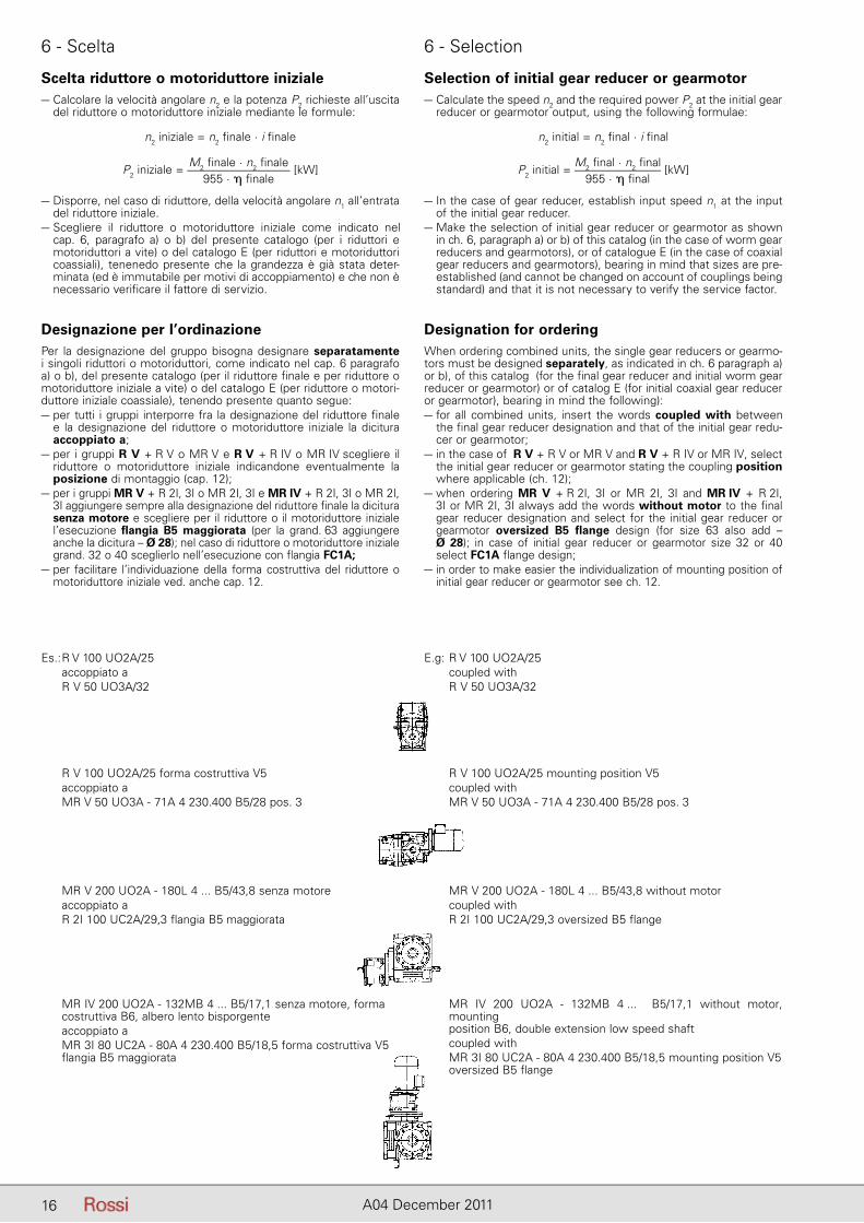
Es.: R V 100 UO2A/25 accoppiato a R V 50 UO3A/32
R V 100 UO2A/25 forma costruttiva V5 accoppiato a MR V 50 UO3A - 71A 4 230.400 B5/28 pos. 3
MR V 200 UO2A - 180L 4 ... B5/43,8 senza motore accoppiato a R 2I 100 UC2A/29,3 flangia B5 maggiorata
MR IV 200 UO2A - 132MB 4 ... B5/17,1 senza motore, forma costruttiva B6, albero lento bisporgente accoppiato a MR 3I 80 UC2A - 80A 4 230.400 B5/18,5 forma costruttiva V5 flangia B5 maggiorata
E.g: R V 100 UO2A/25 coupled with R V 50 UO3A/32
R V 100 UO2A/25 mounting position V5 coupled with MR V 50 UO3A - 71A 4 230.400 B5/28 pos. 3
MR V 200 UO2A - 180L 4 ... B5/43,8 without motor coupled with R 2I 100 UC2A/29,3 oversized B5 flange
MR IV 200 UO2A - 132MB 4 ... B5/17,1 without motor, mounting
position B6, double extension low speed shaft coupled with
MR 3I 80 UC2A - 80A 4 230.400 B5/18,5 mounting position V5 oversized B5 flange
17A04 December 2011
6 - Scelta 6 - Selection
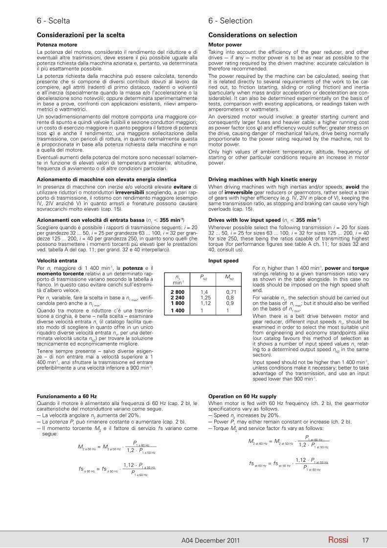
Funzionamento a 60 HzQuando il motore è alimentato alla frequenza di 60 Hz (cap. 2 b), le caratteristiche del motoriduttore variano come segue.– La velocità angolare n2 aumenta del 20%.– La potenza P1 può rimanere costante o aumentare (cap. 2 b).– Il momento torcente M2 e il fattore di servizio fs variano come
segue:
M2 a 60 Hz = M2 a 50 Hz · P1 a 60 Hz
1,2 · P1 a 50 Hz
fs a 60 Hz = fs a 50 Hz · 1,12 · P1 a 50 Hz
P1 a 60 Hz
Operation on 60 Hz supplyWhen motor is fed with 60 Hz frequency (ch. 2 b), the gearmotor specifications vary as follows.– Speed n2 increases by 20%.– Power P1 may either remain constant or increase (ch. 2 b).– Torque M2 and service factor fs vary as follows:
M2 at 60 Hz = M2 at 50 Hz · P1 at 60 Hz
1,2 · P1 at 50 Hz
fs at 60 Hz = fs at 50 Hz · 1,12 · P1 at 50 Hz
P1 at 60 Hz
Considerazioni per la sceltaPotenza motoreLa potenza del motore, considerato il rendimento del riduttore e di eventuali altre trasmissioni, deve essere il più possibile uguale alla potenza richiesta dalla macchina azionata e, pertanto, va determinata il più esattamente possibile.La potenza richiesta dalla macchina può essere calcolata, tenendo presente che si compone di diversi contributi dovuti al lavoro da compiere, agli attriti (radenti di primo distacco, radenti o volventi) e all’inerzia (specialmente quando la massa e/o l’accelerazione o la decelerazione sono notevoli); oppure determinata sperimentalmente in base a prove, confronti con applicazioni esistenti, rilievi ampero-metrici o wattmetrici.Un sovradimensionamento del motore comporta una maggiore cor-rente di spunto e quindi valvole fusibili e sezione conduttori maggiori; un costo di esercizio maggiore in quanto peggiora il fattore di potenza (cos �) e anche il rendimento; una maggiore sollecitazione della trasmissione, con pericoli di rottura, in quanto normalmente questa è proporzionata in base alla potenza richiesta dalla macchina e non a quella del motore.Eventuali aumenti della potenza del motore sono necessari solamen-te in funzione di elevati valori di temperatura ambiente, altitudine, frequenza di avviamento o di altre condizioni particolari.
Azionamento di macchine con elevata energia cineticaIn presenza di macchine con inerzie e/o velocità elevate evitare di utilizzare riduttori o motoriduttori irreversibili scegliendo, a pari rap-porto di trasmissione, il rotismo con rendimento maggiore (esempio IV, 2IV anziché V) in quanto arresti e frenature possono causare sovraccarichi molto elevati (cap. 15).
Azionamenti con velocità di entrata bassa (n1 � 355 min-1)Scegliere quando è possibile i rapporti di trasmissione seguenti: i = 20 per grandezze 32 ... 50, i = 25 per grandezze 63 ... 100, i = 32 per gran-dezze 125 ... 200, i = 40 per grandezza 250, in quanto sono quelli che possono trasmettere i momenti torcenti più elevati (per le prestazioni ved. tabella A del cap. 11; per grand. 32 e 40 interpellarci).
Velocità entrataPer n1 maggiore di 1 400 min-1, la potenza e il momento torcente relativi a un determi nato rap-porto di trasmissione variano se condo la tabella a fianco. In questo caso evi tare carichi sull’estremi-tà d’albero veloce.Per n1 variabile, fare la scelta in base a n1 max, verifi-candola però an che a n1 min.Quando tra motore e riduttore c’è una trasmis-sione a cinghia, è bene – nella scelta – esaminare di verse velocità entrata n1 (il ca talogo facilita que-sto modo di scegliere in quanto offre in un unico riquadro diverse velocità entrata n1, per una deter-minata ve lo cità uscita nN2) per trovare la soluzione tec nicamente ed economicamente migliore.Tenere sempre presente – salvo diverse esigen-ze – di non entrare mai a velocità superiore a 1 400 min-1, anzi sfruttare la trasmissione ed entrare preferibilmente a una velocità inferiore a 900 min-1.
Considerations on selectionMotor powerTaking into account the efficiency of the gear reducer, and other drives – if any – motor power is to be as near as possible to the power rating required by the driven machine: accurate calculation is therefore recommended.The power required by the machine can be calculated, seeing that it is related directly to several requirements of the work to be car-ried out, to friction (starting, sliding or rolling friction) and inertia (particularly when mass and/or acceleration or deceleration are con-siderable). It can also be determined experimentally on the basis of tests, comparison with existing applications, or readings taken with amperometers or wattmeters.An oversized motor would involve: a greater starting current and consequently larger fuses and heavier cable; a higher running cost as power factor (cos �) and efficiency would suffer; greater stress on the drive, causing danger of mechanical failure, drive being normally proportionate to the power rating required by the machine, not to motor power.Only high values of ambient temperature, altitude, frequency of starting or other particular conditions require an increase in motor power.
Driving machines with high kinetic energyWhen driving machines with high inertias and/or speeds, avoid the use of irreversible gear reducers or gearmotors, rather select a train of gears with higher efficiency (e.g. IV, 2IV in place of V), keeping the same transmission ratio, as stopping and braking can cause very high overloads (cap. 15).
Drives with low input speed (n1 � 355 min-1)Wherever possible select the following transmission i = 20 for sizes 32 ... 50, i = 25 for sizes 63 ... 100, i = 32 for sizes 125 ... 200, i = 40 for size 250, these being the ratios capable of transmitting highest torque (for performance figures see table A ch. 11; for sizes 32 and 40, consult us).
Input speedFor n1 higher than 1 400 min-1, power and torque ratings relating to a given transmission ratio vary as shown in the table alongside. In this case no loads should be imposed on the high speed shaft end.For variable n1, the selection should be carried out on the basis of n1 max; but it should also be verified on the basis of n1 min.When there is a belt drive between motor and gear reducer, different input speeds n1, should be examined in order to select the most suitable unit from engineering and economy standpoints alike (our catalog favours this method of selection as it shows a number of input speed values n1 relat-ing to a determined output speed nN2 in the same section).Input speed should not be higher than 1 400 min-1, unless conditions make it necessary; better to take advantage of the transmission, and use an input speed lower than 900 min-1.
n1 PN2 MN2 min-1 2 800 1,4 0,71 2 240 1,25 0,8 1 800 1,12 0,9 1 400 1 1
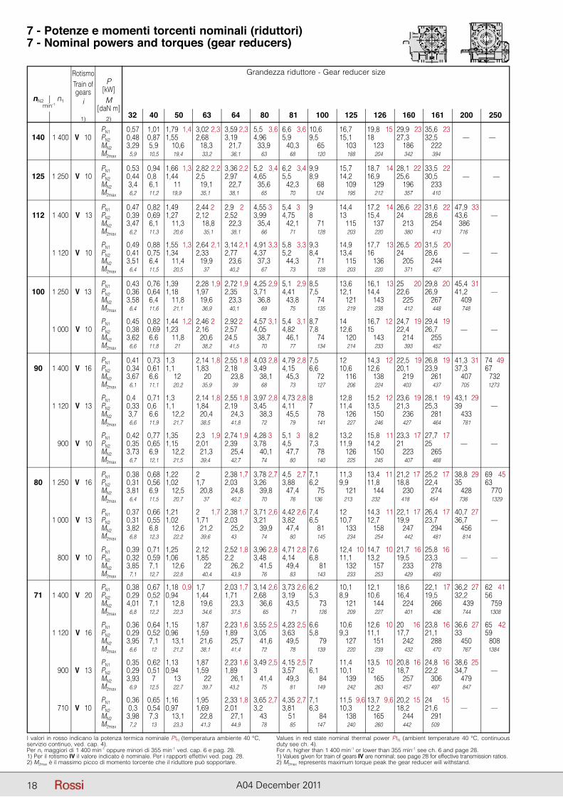
18 A04 December 2011
I valori in rosso indicano la potenza termica nominale PtN (temperatura ambiente 40 °C, servizio continuo, ved. cap. 4).Per n1 maggiori di 1 400 min-1 oppure minori di 355 min-1 ved. cap. 6 e pag. 28.1) Per il rotismo IV il valore indicato è nominale. Per i rapporti effettivi ved. pag. 28.2) M2max è il massimo picco di momento torcente che il riduttore può sopportare.
Values in red state nominal thermal power PtN (ambient temperature 40 °C, continuous duty see ch. 4).For n1 higher than 1 400 min-1 or lower than 355 min-1 see ch. 6 and page 28.1) Values given for train of gears IV are nominal; see page 28 for effective transmission ratios.2) M2max represents maximum torque peak the gear reducer will withstand.
7 - Potenze e momenti torcenti nominali (riduttori)7 - Nominal powers and torques (gear reducers)
Grandezza riduttore - Gear reducer size
32 40 50 63 64 80 81 100 125 126 160 161 200 250
nN2 n1min-1
RotismoTrain ofgears
i
1)
P[kW]M
[daN m]2)
PN1 0,57 1,01 1,79 1,4 3,02 2,3 3,59 2,3 5,5 3,6 6,6 3,6 10,6 16,7 19,8 15 29,9 23 35,6 23 140 1 400 V 10 PN2 0,48 0,87 1,55 2,68 3,19 4,96 5,9 9,5 15,1 18 27,3 32,5 — — MN2 3,29 5,9 10,6 18,3 21,7 33,9 40,3 65 103 123 186 222 M2max 5,9 10,5 19,4 33,2 36,1 63 68 120 188 204 342 394
PN1 0,53 0,94 1,66 1,3 2,82 2,2 3,36 2,2 5,2 3,4 6,2 3,4 9,9 15,7 18,7 14 28,1 22 33,5 22 125 1 250 V 10 PN2 0,44 0,82 1,44 2,5 2,97 4,65 5,5 8,9 14,2 16,9 25,6 30,5 — — MN2 3,4 6,1 11 19,1 22,7 35,6 42,3 68 109 129 196 233 M2max 6,2 11,2 19,9 35,1 38,1 65 70 124 195 212 357 410
PN1 0,47 0,82 1,49 2,44 2,1 2,9 2,1 4,55 3,1 5,4 3,1 9 14,4 17,2 14 26,6 22 31,6 22 47,9 33 112 1 400 V 13 PN2 0,39 0,69 1,27 2,12 2,52 3,99 4,75 8 13 15,4 24 28,6 43,6 — MN2 3,47 6,1 11,3 18,8 22,3 35,4 42,1 71 115 137 213 254 386 M2max 6,2 11,3 20,6 35,1 38,1 66 71 128 203 220 380 413 716
PN1 0,49 0,88 1,55 1,3 2,64 2,1 3,14 2,1 4,91 3,3 5,8 3,3 9,3 14,9 17,7 13 26,5 20 31,5 20 1 120 V 10 PN2 0,41 0,75 1,34 2,33 2,77 4,37 5,2 8,4 13,4 16 24 28,6 — — MN2 3,51 6,4 11,4 19,9 23,6 37,3 44,3 71 115 136 205 244 M2max 6,4 11,5 20,5 37 40,2 67 73 128 203 220 371 427
PN1 0,43 0,76 1,39 2,28 1,9 2,72 1,9 4,25 2,9 5,1 2,9 8,5 13,6 16,1 13 25 20 29,8 20 45,4 31 100 1 250 V 13 PN2 0,36 0,64 1,18 1,97 2,35 3,71 4,41 7,5 12,1 14,4 22,6 26,9 41,2 — MN2 3,58 6,4 11,8 19,6 23,3 36,8 43,8 74 121 143 225 267 409 M2max 6,4 11,6 21,1 36,9 40,1 69 75 135 219 238 412 448 748
PN1 0,45 0,82 1,44 1,2 2,46 2,1 2,92 2,1 4,57 3,1 5,4 3,1 8,7 14 16,7 12 24,7 19 29,4 19 1 000 V 10 PN2 0,38 0,69 1,23 2,16 2,57 4,05 4,82 7,8 12,6 15 22,4 26,7 — — MN2 3,62 6,6 11,8 20,6 24,5 38,7 46,1 74 120 143 214 255 M2max 6,6 11,8 21 38,2 41,5 70 77 134 214 233 393 452
PN1 0,41 0,73 1,3 2,14 1,8 2,55 1,8 4,03 2,8 4,79 2,8 7,5 12 14,3 12 22,5 19 26,8 19 41,3 31 74 49 90 1 400 V 16 PN2 0,34 0,61 1,1 1,83 2,18 3,49 4,15 6,6 10,6 12,6 20,1 23,9 37,3 67 MN2 3,67 6,6 12 20 23,8 38,1 45,3 72 116 138 219 261 407 732 M2max 6,1 11,1 20,2 35,9 39 68 73 127 206 224 403 437 705 1273
PN1 0,41 0,71 1,3 2,14 1,8 2,55 1,8 3,97 2,8 4,73 2,8 8 12,8 15,2 12 23,6 19 28,1 19 43,1 29 1 120 V 13 PN2 0,33 0,61 1,1 1,84 2,19 3,45 4,11 7 11,4 13,5 21,3 25,3 39 — MN2 3,7 6,6 12,2 20,4 24,3 38,3 45,5 78 126 150 236 281 433 M2max 6,6 11,9 21,7 38,5 41,8 72 79 141 227 246 427 464 781
PN1 0,42 0,77 1,35 2,3 1,9 2,74 1,9 4,28 3,1 5,1 3,1 8,2 13,2 15,8 11 23,3 17 27,7 17 900 V 10 PN2 0,35 0,65 1,15 2,01 2,39 3,78 4,5 7,3 11,9 14,2 21 25 — — MN2 3,73 6,9 12,2 21,3 25,4 40,1 47,7 78 126 150 223 265 M2max 6,7 12,1 21,5 39,4 42,7 74 80 140 225 245 407 468
PN1 0,38 0,68 1,22 2 2,38 1,7 3,78 2,7 4,5 2,7 7,1 11,3 13,4 11 21,2 17 25,2 17 38,8 29 69 45 80 1 250 V 16 PN2 0,31 0,56 1,02 1,7 2,03 3,26 3,88 6,2 9,9 11,8 18,8 22,4 35 63 MN2 3,81 6,9 12,5 20,8 24,8 39,8 47,4 75 121 144 230 274 428 770 M2max 6,4 11,5 20,7 37 40,2 70 76 136 213 232 418 454 736 1329
PN1 0,37 0,66 1,21 2 1,7 2,38 1,7 3,71 2,6 4,42 2,6 7,4 12 14,3 11 22,1 17 26,4 17 40,7 27 1 000 V 13 PN2 0,31 0,55 1,02 1,71 2,03 3,21 3,82 6,5 10,7 12,7 19,9 23,7 36,7 — MN2 3,82 6,8 12,6 21,2 25,2 39,9 47,4 81 133 158 247 294 456 M2max 6,8 12,3 22,2 39,6 43 74 80 145 234 254 442 481 814
PN1 0,39 0,71 1,25 2,12 2,52 1,8 3,96 2,8 4,71 2,8 7,6 12,4 10 14,7 10 21,7 16 25,8 16 800 V 10 PN2 0,32 0,59 1,06 1,85 2,2 3,48 4,14 6,8 11,1 13,2 19,5 23,3 — — MN2 3,85 7,1 12,6 22 26,2 41,5 49,4 81 132 157 233 278 M2max 7,1 12,7 22,8 40,4 43,9 76 83 143 233 253 429 493
PN1 0,38 0,67 1,18 0,9 1,7 2,03 1,7 3,14 2,6 3,73 2,6 6,2 10,1 12,1 18,6 22,1 17 36,2 27 62 41 71 1 400 V 20 PN2 0,29 0,52 0,94 1,44 1,71 2,68 3,19 5,3 8,9 10,6 16,4 19,5 32,2 56 MN2 4,01 7,1 12,8 19,6 23,3 36,6 43,5 73 121 144 224 266 439 759 M2max 6,8 12,2 22,3 34,6 37,5 65 71 126 209 227 401 436 744 1308
PN1 0,36 0,64 1,15 1,87 2,23 1,6 3,55 2,5 4,23 2,5 6,6 10,6 12,6 10 20 16 23,8 16 36,6 27 65 42 1 120 V 16 PN2 0,29 0,52 0,96 1,59 1,89 3,05 3,63 5,8 9,3 11,1 17,7 21,1 33 59 MN2 3,95 7,1 13,1 21,6 25,7 41,6 49,5 79 127 151 242 288 450 808 M2max 6,6 12 21,2 38,1 41,4 72 78 139 220 239 432 470 767 1384
PN1 0,35 0,62 1,13 1,87 2,23 1,6 3,49 2,5 4,15 2,5 7 11,4 13,5 10 20,8 16 24,8 16 38,6 25 900 V 13 PN2 0,29 0,51 0,94 1,59 1,89 3 3,57 6,1 10,1 12 18,7 22,2 34,7 — MN2 3,93 7 13 22 26,1 41,4 49,3 84 139 165 257 306 479 M2max 6,9 12,5 22,7 39,7 43,2 75 81 149 242 263 457 497 847
PN1 0,36 0,65 1,16 1,95 2,33 1,8 3,65 2,7 4,35 2,7 7,1 11,5 9,6 13,7 9,6 20,2 15 24 15 710 V 10 PN2 0,3 0,54 0,97 1,69 2,01 3,2 3,81 6,3 10,3 12,2 18,2 21,6 — — MN2 3,98 7,3 13,1 22,8 27,1 43 51 84 138 165 244 291 M2max 7,2 13 23,3 41,3 44,9 78 85 147 240 260 442 509
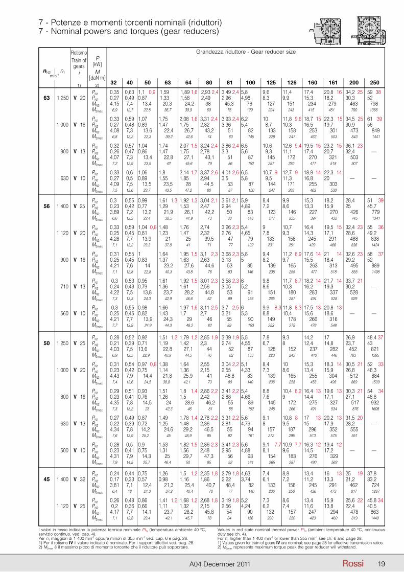
Grandezza riduttore - Gear reducer size
32 40 50 63 64 80 81 100 125 126 160 161 200 250
nN2 n1min-1
RotismoTrain ofgears
i
1)
P[kW]M
[daN m]2)
19A04 December 2011
I valori in rosso indicano la potenza termica nominale PtN (temperatura ambiente 40 °C, servizio continuo, ved. cap. 4).Per n1 maggiori di 1 400 min-1 oppure minori di 355 min-1 ved. cap. 6 e pag. 28.1) Per il rotismo IV il valore indicato è nominale. Per i rapporti effettivi ved. pag. 28.2) M2max è il massimo picco di momento torcente che il riduttore può sopportare.
Values in red state nominal thermal power PtN (ambient temperature 40 °C, continuous duty see ch. 4).For n1 higher than 1 400 min-1 or lower than 355 min-1 see ch. 6 and page 28.1) Values given for train of gears IV are nominal; see page 28 for effective transmission ratios.2) M2max represents maximum torque peak the gear reducer will withstand.
7 - Potenze e momenti torcenti nominali (riduttori)7 - Nominal powers and torques (gear reducers)
Grandezza riduttore - Gear reducer size
32 40 50 63 64 80 81 100 125 126 160 161 200 250
nN2 n1min-1
RotismoTrain ofgears
i
1)
P[kW]M
[daN m]2)
PN1 0,35 0,63 1,1 0,9 1,59 1,89 1,6 2,93 2,4 3,49 2,4 5,8 9,6 11,4 17,4 20,8 16 34,2 25 59 38 63 1 250 V 20 PN2 0,27 0,49 0,87 1,33 1,58 2,49 2,96 4,98 8,3 9,9 15,3 18,2 30,3 52 MN2 4,15 7,4 13,4 20,3 24,2 38 45,3 76 127 151 234 279 463 798 M2max 6,9 12,7 22,8 36,7 39,9 69 75 129 224 243 415 451 790 1366
PN1 0,33 0,59 1,07 1,75 2,08 1,6 3,31 2,4 3,93 2,4 6,2 10 11,8 9,6 18,7 15 22,3 15 34,5 25 61 39 1 000 V 16 PN2 0,27 0,48 0,89 1,47 1,75 2,82 3,36 5,4 28,7 10,3 16,5 19,7 30,9 56 MN2 4,08 7,3 13,6 22,4 26,7 43,2 51 82 133 158 253 301 473 849 M2max 6,8 12,2 22,3 39,2 42,6 74 80 145 228 247 463 503 843 1441
PN1 0,32 0,57 1,04 1,74 2,07 1,5 3,24 2,4 3,86 2,4 6,5 10,6 12,6 9,4 19,5 15 23,2 15 36,1 23 800 V 13 PN2 0,26 0,47 0,86 1,47 1,75 2,78 3,3 5,6 29,3 11,1 17,4 20,7 32,4 — MN2 4,07 7,3 13,4 22,8 27,1 43,1 51 87 145 172 270 321 503 M2max 7,2 12,9 23,9 42 45,6 79 86 152 257 280 477 518 907
PN1 0,33 0,6 1,06 1,8 2,14 1,7 3,37 2,6 4,01 2,6 6,5 10,7 9,1 12,7 9,1 18,8 14 22,3 14 630 V 10 PN2 0,27 0,5 0,89 1,55 1,85 2,94 3,5 5,8 29,5 11,3 16,8 20 — — MN2 4,09 7,5 13,5 23,5 28 44,5 53 87 144 171 255 303 M2max 7,5 13,6 23,7 43,5 47,2 80 87 150 247 268 463 533
PN1 0,36 0,55 0,99 1,61 1,3 1,92 1,3 3,04 2,1 3,61 2,1 5,9 8,4 9,9 15,3 18,2 28,4 51 39 56 1 400 V 25 PN2 0,23 0,42 0,77 1,29 1,53 2,47 2,94 4,89 7,2 8,6 13,3 15,9 25 45,7 MN2 3,89 7,2 13,2 21,9 26,1 42,2 50 83 123 146 227 270 426 779 M2max 6,6 12,3 22,4 38,5 41,9 73 80 148 217 235 397 432 745 1341
PN1 0,33 0,59 1,04 0,8 1,48 1,76 2,74 3,26 2,3 5,4 9 10,7 16,4 19,5 15 32,4 23 55 36 1 120 V 20 PN2 0,25 0,45 0,81 1,23 1,47 2,32 2,76 4,65 7,8 9,3 14,3 17,1 28,6 49,2 MN2 4,28 7,7 13,9 21 25 39,5 47 79 133 158 245 291 488 838 M2max 7,1 13,2 23,3 37,8 41 71 77 132 231 251 429 466 836 1424
PN1 0,31 0,55 1 1,64 1,95 1,5 3,1 2,3 3,68 2,3 5,8 9,4 11,2 8,9 17,6 14 21 14 32,6 23 58 37 900 V 16 PN2 0,25 0,45 0,83 1,37 1,63 2,63 3,13 5 8,2 9,7 15,5 18,4 29,2 52 MN2 4,21 7,6 14 23,2 27,6 44,6 53 85 139 165 263 313 495 889 M2max 7,1 12,8 22,8 40,3 43,8 76 83 146 235 255 477 518 855 1498
PN1 0,3 0,53 0,95 1,61 1,92 1,5 3,01 2,3 3,58 2,3 6 9,8 11,7 8,7 18,2 14 21,7 14 33,7 21 710 V 13 PN2 0,24 0,43 0,79 1,36 1,61 2,56 3,05 5,2 8,6 10,3 16,2 19,3 30,2 — MN2 4,22 7,5 13,8 23,7 28,2 44,8 53 91 151 180 283 337 528 M2max 7,3 13,3 24,3 42,9 46,6 82 89 156 265 287 494 528 929
PN1 0,3 0,55 0,98 1,66 1,97 1,6 3,11 2,5 3,7 2,5 6 9,9 8,3 11,8 8,3 17,5 13 20,8 13 560 V 10 PN2 0,25 0,45 0,82 1,43 1,7 2,7 3,21 5,3 8,8 10,4 15,6 18,6 — — MN2 4,21 7,7 13,9 24,3 29 46 55 90 149 178 266 316 M2max 7,7 13,9 24,9 44,3 48,2 82 89 153 253 275 476 548
PN1 0,28 0,52 0,92 1,51 1,2 1,79 1,2 2,85 1,9 3,39 1,9 5,5 7,8 9,3 14,2 17 26,9 48,4 37 50 1 250 V 25 PN2 0,21 0,39 0,71 1,19 1,42 2,3 2,74 4,55 6,7 8 12,4 14,8 23,7 43 MN2 4,03 7,5 13,6 22,8 27,1 44 52 87 128 152 237 282 452 821 M2max 6,9 12,5 22,9 40,9 44,5 76 82 153 223 243 410 446 783 1395
PN1 0,31 0,54 0,97 0,8 1,38 1,64 2,55 3,04 2,2 5,1 8,4 10 15,3 18,3 14 30,5 21 52 33 1 000 V 20 PN2 0,23 0,42 0,75 1,14 1,36 2,15 2,55 4,33 7,3 8,6 13,4 15,9 26,8 46,3 MN2 4,43 7,9 14,4 21,8 25,9 41 48,8 83 139 165 255 304 512 884 M2max 7,4 13,6 24,5 38,8 42,1 73 80 140 238 258 458 498 869 1509
PN1 0,29 0,51 0,93 1,51 1,8 1,4 2,86 2,2 3,41 2,2 5,4 8,8 10,4 8,2 16,4 13 19,6 13 30,3 21 54 34 800 V 16 PN2 0,23 0,41 0,76 1,26 1,5 2,42 2,88 4,66 7,6 9 14,4 17,1 27,1 48,8 MN2 4,35 7,8 14,5 24 28,6 46,2 55 89 145 172 275 327 517 932 M2max 7,3 13,2 23 42,3 46 81 88 152 245 266 491 534 876 1608
PN1 0,27 0,49 0,87 1,49 1,78 1,4 2,78 2,2 3,31 2,2 5,6 9,1 10,8 8 17 13 20,2 13 31,5 20 630 V 13 PN2 0,22 0,39 0,72 1,25 1,48 2,36 2,81 4,79 8 9,5 15 17,9 28,2 — MN2 4,34 7,8 14,2 24,6 29,2 46,5 55 94 157 187 296 352 555 M2max 7,6 13,9 25,2 45 48,9 85 92 161 272 295 513 575 951
PN1 0,28 0,5 0,9 1,53 1,82 1,5 2,86 2,3 3,41 2,3 5,6 9,1 7,7 10,9 7,7 16,3 12 19,4 12 500 V 10 PN2 0,23 0,41 0,75 1,31 1,56 2,48 2,95 4,88 8,1 9,6 14,5 17,2 — — MN2 4,31 7,9 14,3 25 29,7 47,3 56 93 154 183 276 329 M2max 7,9 14,5 25,7 46,4 50 85 92 161 265 287 490 563
PN1 0,24 0,44 0,75 1,26 1,5 1,2 2,35 1,8 2,79 1,8 4,63 7,4 8,8 13,4 16 13 25 19 37,8 45 1 400 V 32 PN2 0,17 0,33 0,57 0,98 1,16 1,86 2,22 3,74 6,1 7,2 11,2 13,3 21,2 33,2 MN2 3,81 7,1 12,4 21,3 25,4 40,7 48,4 82 133 158 245 291 462 724 M2max 6,4 12 21,3 37,2 40,4 70 77 140 236 256 436 473 817 1287
PN1 0,26 0,48 0,86 1,41 1,2 1,68 1,2 2,68 1,8 3,19 1,8 5,2 7,3 8,6 13,4 15,9 25,6 22 45,8 34 1 120 V 25 PN2 0,2 0,36 0,66 1,11 1,32 2,15 2,56 4,24 6,2 7,4 11,6 13,8 22,4 40,5 MN2 4,17 7,7 14,1 23,7 28,2 45,8 54 90 132 157 247 294 478 863 M2max 7,1 12,8 23,4 42,1 45,7 78 84 156 230 250 423 460 819 1449
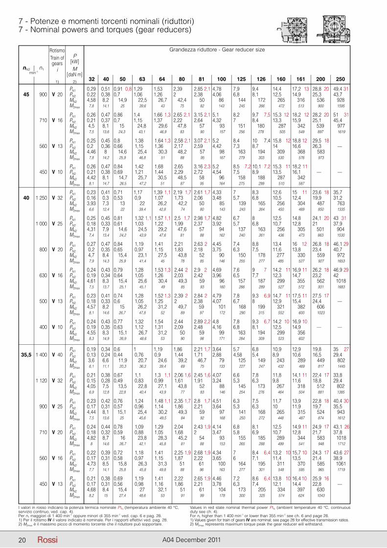
20 A04 December 2011
I valori in rosso indicano la potenza termica nominale PtN (temperatura ambiente 40 °C, servizio continuo, ved. cap. 4).Per n1 maggiori di 1 400 min-1 oppure minori di 355 min-1 ved. cap. 6 e pag. 28.1) Per il rotismo IV il valore indicato è nominale. Per i rapporti effettivi ved. pag. 28.2) M2max è il massimo picco di momento torcente che il riduttore può sopportare.
Values in red state nominal thermal power PtN (ambient temperature 40 °C, continuous duty see ch. 4).For n1 higher than 1 400 min-1 or lower than 355 min-1 see ch. 6 and page 28.1) Values given for train of gears IV are nominal; see page 28 for effective transmission ratios.2) M2max represents maximum torque peak the gear reducer will withstand.
7 - Potenze e momenti torcenti nominali (riduttori)7 - Nominal powers and torques (gear reducers)
Grandezza riduttore - Gear reducer size
32 40 50 63 64 80 81 100 125 126 160 161 200 250
nN2 n1min-1
RotismoTrain ofgears
i
1)
P[kW]M
[daN m]2)
PN1 0,29 0,51 0,91 0,8 1,29 1,53 2,39 2,85 2,1 4,78 7,9 9,4 14,4 17,2 13 28,8 20 49,4 31 45 900 V 20 PN2 0,22 0,38 0,7 1,06 1,26 2 2,38 4,06 6,8 8,1 12,5 14,9 25,3 43,7 MN2 4,58 8,2 14,9 22,5 26,7 42,4 50 86 144 172 265 316 536 928 M2max 7,8 14,1 25 39,6 43 75 82 143 245 266 472 513 900 1595
PN1 0,26 0,47 0,86 1,4 1,66 1,3 2,65 2,1 3,15 2,1 5,1 8,2 9,7 7,5 15,3 12 18,2 12 28,2 20 51 31 710 V 16 PN2 0,21 0,37 0,7 1,15 1,37 2,22 2,64 4,32 7 8,4 13,3 15,9 25,1 45,4 MN2 4,5 8,1 15 24,8 29,6 47,8 57 93 151 180 287 342 539 977 M2max 7,5 13,6 24,3 43,1 46,9 83 90 157 256 278 505 549 897 1619
PN1 0,25 0,45 0,8 1,38 1,64 1,3 2,58 2,1 3,07 2,1 5,2 8,4 10 7,4 15,8 12 18,8 12 29,5 18 560 V 13 PN2 0,22 0,36 0,66 1,15 1,36 2,17 2,59 4,42 7,3 8,7 14 16,6 26,3 — MN2 4,46 8 14,6 25,4 30,3 48,2 57 98 163 194 309 368 583 M2max 7,8 14,2 25,9 46,8 51 88 95 167 279 303 530 576 973
PN1 0,26 0,47 0,84 1,42 1,68 2,65 3,16 2,3 5,2 8,5 7,2 10,1 7,2 15,3 11 18,2 11 450 V 10 PN2 0,21 0,38 0,69 1,21 1,44 2,29 2,72 4,54 7,5 8,9 13,5 16,1 — — MN2 4,42 8,1 14,7 25,7 30,5 48,5 58 96 158 188 287 342 M2max 8,1 14,7 26,5 47,2 51 87 95 164 275 299 510 587
PN1 0,23 0,41 0,71 1,17 1,39 1,1 2,19 1,7 2,61 1,7 4,33 7 8,3 12,6 15 11,1 23,6 18 35,7 40 1 250 V 32 PN2 0,16 0,3 0,53 0,9 1,07 1,73 2,06 3,48 5,7 6,8 10,5 12,4 19,9 31,2 MN2 3,93 7,3 13 22 26,2 42,2 50 85 139 165 256 304 487 763 M2max 6,6 12,4 22 39,4 42,8 74 80 143 243 264 450 489 850 1335
PN1 0,25 0,45 0,81 1,32 1,1 1,57 1,1 2,5 1,7 2,98 1,7 4,82 6,7 8 12,5 14,8 24,1 20 43 31 1 000 V 25 PN2 0,18 0,33 0,61 1,03 1,22 1,99 2,37 3,92 5,7 6,8 10,7 12,8 21 37,9 MN2 4,31 7,9 14,6 24,5 29,2 47,6 57 94 137 163 256 305 501 904 M2max 7,4 13,4 24,2 43,9 47,6 81 88 162 240 261 436 473 863 1530
PN1 0,27 0,47 0,84 1,19 1,41 2,21 2,63 2 4,45 7,4 8,8 13,4 16 12 26,8 18 46,1 29 800 V 20 PN2 0,2 0,35 0,65 0,97 1,15 1,83 2,18 3,75 6,3 7,5 11,6 13,8 23,4 40,7 MN2 4,7 8,4 15,4 23,1 27,5 43,8 52 90 150 178 277 330 559 972 M2max 7,9 14,3 25,9 41,4 45 78 85 146 255 277 485 527 927 1653
PN1 0,24 0,43 0,79 1,28 1,53 1,3 2,44 2 2,9 2 4,69 7,6 9 7 14,2 11 16,9 11 26,2 18 46,9 29 630 V 16 PN2 0,19 0,34 0,64 1,05 1,26 2,03 2,42 3,96 6,5 7,7 12,3 14,7 23,2 42 MN2 4,61 8,3 15,4 25,6 30,4 49,3 59 96 157 187 299 355 562 1018 M2max 7,5 13,7 25,1 45,1 49 85 93 160 266 289 527 572 931 1683
PN1 0,23 0,41 0,74 1,28 1,52 1,3 2,39 2 2,84 2 4,79 7,8 9,3 6,9 14,7 11 17,5 11 27,5 17 500 V 13 PN2 0,18 0,33 0,6 1,05 1,25 2 2,38 4,07 6,7 8 12,9 15,4 24,4 — MN2 4,57 8,2 15 26,2 31,2 49,7 59 101 168 199 321 382 606 M2max 8,1 14,6 26,7 47,8 52 89 97 172 290 315 552 600 1023
PN1 0,24 0,43 0,77 1,32 1,54 2,44 2,89 2,2 4,8 7,8 9,3 6,7 14,2 10 16,9 10 400 V 10 PN2 0,19 0,35 0,63 1,12 1,31 2,09 2,48 4,16 6,8 8,1 12,5 14,9 — — MN2 4,55 8,3 15,1 26,7 31,2 50 59 99 163 194 299 356 M2max 8,3 14,9 26,9 48,6 53 90 98 171 284 309 523 602
PN1 0,19 0,34 0,6 1 1,19 1,86 2,21 1,7 3,64 5,7 6,8 10,9 12,9 19,8 35 27 35,5 1 400 V 40 PN2 0,13 0,24 0,44 0,76 0,9 1,44 1,71 2,88 4,58 5,4 8,9 10,6 16,5 29,4 MN2 3,6 6,6 11,9 20,7 24,6 39,2 46,7 79 125 149 243 289 449 802 M2max 6,1 11,1 20,3 36,3 39,4 69 75 133 227 247 432 469 817 1445
PN1 0,21 0,38 0,67 1,1 1,3 1,1 2,06 1,6 2,45 1,6 4,07 6,6 7,8 11,8 14,1 11 22,4 17 33,8 1 120 V 32 PN2 0,15 0,28 0,49 0,83 0,99 1,61 1,91 3,24 5,3 6,3 9,8 11,6 18,8 29,4 MN2 4,05 7,5 13,5 22,8 27,1 43,8 52 88 145 173 267 318 512 802 M2max 6,9 12,8 22,8 40,4 43,9 77 83 146 254 276 464 504 881 1385
PN1 0,23 0,42 0,76 1,24 1,48 1,1 2,35 1,7 2,8 1,7 4,51 6,3 7,5 11,7 13,9 22,8 18 40,4 30 900 V 25 PN2 0,17 0,31 0,57 0,96 1,14 1,86 2,21 3,64 5,3 6,3 10 11,9 19,7 35,5 MN2 4,44 8,1 15,1 25,4 30,2 49,3 59 97 141 168 265 315 524 943 M2max 7,5 13,6 25 45,6 49,5 84 92 168 250 272 448 487 874 1612
PN1 0,24 0,44 0,78 1,09 1,29 2,04 2,43 1,9 4,14 6,8 8,1 12,5 14,9 11 24,9 17 43,1 26 710 V 20 PN2 0,18 0,32 0,59 0,88 1,05 1,68 2 3,47 5,8 6,9 10,7 12,8 21,7 37,8 MN2 4,82 8,7 16 23,8 28,3 45,2 54 93 155 185 289 344 583 1018 M2max 8 14,6 26,7 42,1 45,8 81 88 153 265 288 499 541 948 1712
PN1 0,22 0,39 0,72 1,18 1,41 2,25 1,9 2,68 1,9 4,34 7 8,4 6,4 13,2 10 15,7 10 24,3 17 43,6 27 560 V 16 PN2 0,17 0,31 0,58 0,97 1,15 1,87 2,22 3,65 6 7,1 11,4 13,5 21,4 38,9 MN2 4,73 8,5 15,8 26,3 31,3 51 61 100 164 195 311 370 585 1061 M2max 7,7 14,1 25,8 45,8 49,8 88 96 163 277 301 548 595 965 1719
PN1 0,21 0,38 0,69 1,19 1,41 2,22 2,65 1,9 4,46 7,2 8,6 6,4 13,8 10 16,4 10,1 25,9 16 450 V 13 PN2 0,17 0,31 0,56 0,98 1,16 1,86 2,21 3,78 6,3 7,4 12,1 14,4 22,8 — MN2 4,68 8,4 15,4 27 32,1 51 61 104 173 205 334 397 630 M2max 8,2 15 27,4 48,6 53 91 99 178 300 325 574 624 1043
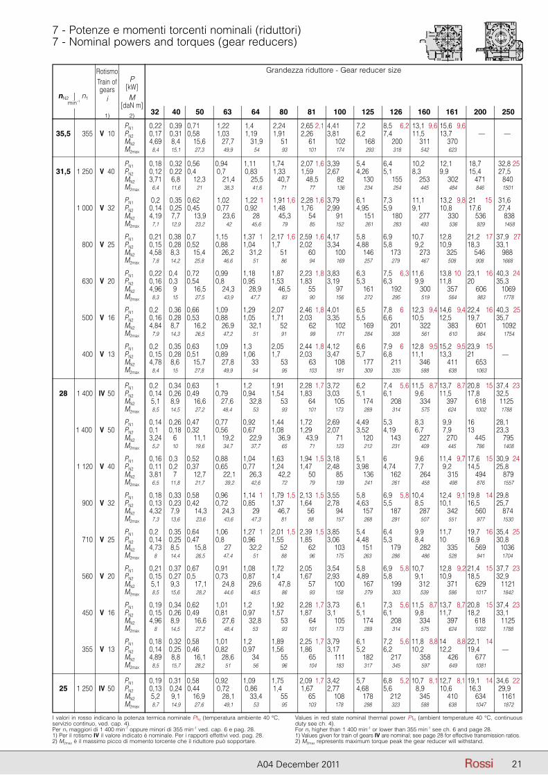
21A04 December 2011
I valori in rosso indicano la potenza termica nominale PtN (temperatura ambiente 40 °C, servizio continuo, ved. cap. 4).Per n1 maggiori di 1 400 min-1 oppure minori di 355 min-1 ved. cap. 6 e pag. 28.1) Per il rotismo IV il valore indicato è nominale. Per i rapporti effettivi ved. pag. 28.2) M2max è il massimo picco di momento torcente che il riduttore può sopportare.
Values in red state nominal thermal power PtN (ambient temperature 40 °C, continuous duty see ch. 4).For n1 higher than 1 400 min-1 or lower than 355 min-1 see ch. 6 and page 28.1) Values given for train of gears IV are nominal; see page 28 for effective transmission ratios.2) M2max represents maximum torque peak the gear reducer will withstand.
7 - Potenze e momenti torcenti nominali (riduttori)7 - Nominal powers and torques (gear reducers)
Grandezza riduttore - Gear reducer size
32 40 50 63 64 80 81 100 125 126 160 161 200 250
nN2 n1min-1
RotismoTrain ofgears
i
1)
P[kW]M
[daN m]2)
PN1 0,22 0,39 0,71 1,22 1,4 2,24 2,65 2,1 4,41 7,2 8,5 6,2 13,1 9,6 15,6 9,6 35,5 355 V 10 PN2 0,17 0,31 0,58 1,03 1,19 1,91 2,26 3,81 6,2 7,4 11,5 13,7 — — MN2 4,69 8,4 15,6 27,7 31,9 51 61 102 168 200 311 370 M2max 8,4 15,1 27,3 49,9 54 93 101 174 293 318 542 623
PN1 0,18 0,32 0,56 0,94 1,11 1,74 2,07 1,6 3,39 5,4 6,4 10,2 12,1 18,7 32,8 25 31,5 1 250 V 40 PN2 0,12 0,22 0,4 0,7 0,83 1,33 1,59 2,67 4,26 5,1 8,3 9,9 15,4 27,5 MN2 3,71 6,8 12,3 21,4 25,5 40,7 48,5 82 130 155 253 302 471 840 M2max 6,4 11,6 21 38,3 41,6 71 77 136 234 254 445 484 846 1501
PN1 0,2 0,35 0,62 1,02 1,22 1 1,91 1,6 2,28 1,6 3,79 6,1 7,3 11,1 13,2 9,8 21 15 31,6 1 000 V 32 PN2 0,14 0,25 0,45 0,77 0,92 1,48 1,76 2,99 4,95 5,9 9,1 10,8 17,6 27,4 MN2 4,19 7,7 13,9 23,6 28 45,3 54 91 151 180 277 330 536 838 M2max 7,1 12,9 23,2 42 45,6 79 85 152 261 283 493 536 929 1458
PN1 0,21 0,38 0,7 1,15 1,37 1 2,17 1,6 2,59 1,6 4,17 5,8 6,9 10,7 12,8 21,2 17 37,9 27 800 V 25 PN2 0,15 0,28 0,52 0,88 1,04 1,7 2,02 3,34 4,88 5,8 19,2 10,9 18,3 33,1 MN2 4,58 8,3 15,4 26,2 31,2 51 60 100 146 173 273 325 546 988 M2max 7,8 14,2 25,8 46,6 51 86 94 169 257 279 467 508 908 1668
PN1 0,22 0,41 0,72 0,99 1,18 1,87 2,23 1,8 3,83 6,3 7,5 6,3 11,6 13,8 10 23,1 16 40,3 24 630 V 20 PN2 0,16 0,31 0,54 0,8 0,95 1,53 1,83 3,19 5,3 6,3 09,9 11,8 20 35,3 MN2 4,96 9 16,5 24,3 28,9 46,5 55 97 161 192 300 357 606 1069 M2max 8,3 15 27,5 43,9 47,7 83 90 156 272 295 519 564 983 1778
PN1 0,21 0,36 0,66 1,09 1,29 2,07 2,46 1,8 4,01 6,5 7,8 6 12,3 9,4 14,6 9,4 22,4 16 40,3 25 500 V 16 PN2 0,16 0,28 0,53 0,88 1,05 1,71 2,03 3,35 5,5 6,6 10,5 12,5 19,7 35,7 MN2 4,84 8,7 16,2 26,9 32,1 52 62 102 169 201 322 383 601 1092 M2max 7,9 14,3 26,5 47,2 51 91 99 171 284 308 561 610 984 1754
PN1 0,21 0,35 0,63 1,09 1,3 2,05 2,44 1,8 4,12 6,6 7,9 6 12,8 9,5 15,2 9,5 23,9 15 400 V 13 PN2 0,15 0,28 0,51 0,89 1,06 1,7 2,03 3,47 5,7 6,8 11,1 13,3 21 — MN2 4,78 8,6 15,7 27,8 33 53 63 108 177 211 346 411 653 M2max 8,4 15 27,8 49,9 54 95 103 181 309 335 588 638 1063
PN1 0,21 0,34 0,63 1 1,2 1,91 2,28 1,7 3,72 6,2 7,4 5,6 11,5 8,7 13,7 8,7 20,8 15 37,4 23 28 1 400 IV 50 PN2 0,14 0,26 0,49 0,79 0,94 1,54 1,83 3,03 5,1 6,1 09,6 11,5 17,8 32,5 MN2 5,1 8,9 16,6 27,6 32,8 53 64 105 174 208 334 397 618 1125 M2max 8,5 14,5 27,2 48,4 53 93 101 173 289 314 575 624 1002 1788
PN1 0,14 0,26 0,47 0,77 0,92 1,44 1,72 2,69 4,49 5,3 08,3 09,9 16 28,1 1 400 V 50 PN2 0,11 0,18 0,32 0,56 0,67 1,08 1,29 2,07 3,52 4,19 06,7 07,9 13 23,3 MN2 3,24 6 11,1 19,2 22,9 36,9 43,9 71 120 143 227 270 445 795 M2max 5,2 10 19,6 34,7 37,7 65 71 123 212 231 409 445 786 1408
PN1 0,16 0,31 0,52 0,88 1,04 1,63 1,94 1,5 3,18 5,1 6 09,6 11,4 9,7 17,6 15 30,9 24 1 120 V 40 PN2 0,11 0,21 0,37 0,65 0,77 1,24 1,47 2,48 3,98 4,74 07,7 09,2 14,5 25,8 MN2 3,81 7 12,7 22,1 26,3 42,2 50 85 136 162 264 315 494 879 M2max 6,5 11,8 21,7 39,2 42,6 72 79 139 241 261 458 498 876 1557
PN1 0,18 0,33 0,58 0,96 1,14 1 1,79 1,5 2,13 1,5 3,55 5,8 6,9 5,8 10,4 12,4 9,1 19,8 14 29,8 900 V 32 PN2 0,13 0,23 0,42 0,72 0,85 1,37 1,64 2,78 4,63 5,5 08,5 10,1 16,5 25,7 MN2 4,32 7,9 14,3 24,3 29 46,7 56 94 157 187 287 342 560 874 M2max 7,3 13,6 23,6 43,6 47,3 81 88 157 268 291 507 551 977 1530
PN1 0,20 0,35 0,64 1,06 1,27 1 2,01 1,5 2,39 1,5 3,85 5,4 6,4 09,9 11,7 19,7 16 35,4 25 710 V 25 PN2 0,14 0,25 0,47 0,8 0,96 1,55 1,85 3,06 4,48 5,3 08,4 10 16,9 30,8 MN2 4,73 8,5 15,8 27 32,2 52 62 103 151 179 282 335 569 1036 M2max 8 14,4 26,5 47,4 51 88 96 175 263 286 486 528 941 1704
PN1 0,21 0,37 0,67 0,91 1,08 1,72 2,05 3,54 5,8 6,9 5,8 10,7 12,8 9,2 21,4 15 37,7 23 560 V 20 PN2 0,15 0,27 0,5 0,73 0,87 1,4 1,67 2,93 4,89 5,8 09,1 10,9 18,5 32,9 MN2 5,1 9,3 17,1 24,8 29,6 47,8 57 100 167 199 312 371 629 1121 M2max 8,5 15,6 28,2 44,6 48,5 86 93 158 279 303 539 586 1017 1842
PN1 0,19 0,34 0,62 1,01 1,2 1,92 2,28 1,7 3,73 6,1 7,3 5,6 11,5 8,7 13,7 8,7 20,8 15 37,4 23 450 V 16 PN2 0,15 0,26 0,49 0,81 0,97 1,57 1,87 3,1 5,1 6,1 09,8 11,7 18,2 33,1 MN2 4,96 8,9 16,6 27,6 32,8 53 64 105 174 208 334 397 618 1125 M2max 8 14,5 27,2 48,4 53 93 101 173 289 314 575 624 1002 1788
PN1 0,18 0,32 0,58 1,01 1,2 1,89 2,25 1,7 3,79 6,1 7,2 5,6 11,8 8,8 14 8,8 22,1 14 355 V 13 PN2 0,14 0,25 0,46 0,82 0,97 1,56 1,86 3,17 5,2 6,2 10,2 12,2 19,4 — MN2 4,89 8,8 16,1 28,6 34 55 65 111 182 217 358 426 677 M2max 8,5 15,7 28,2 51 56 96 104 183 317 345 597 649 1081
PN1 0,19 0,31 0,58 0,92 1,09 1,75 2,09 1,7 3,42 5,7 6,8 5,2 10,7 8,1 12,7 8,1 19,1 14 34,6 22 25 1 250 IV 50 PN2 0,13 0,24 0,44 0,72 0,86 1,4 1,67 2,77 4,68 5,6 08,9 10,6 16,3 29,9 MN2 5,2 9,1 16,9 28,1 33,4 55 65 108 178 212 345 410 634 1161 M2max 8,7 14,9 27,6 49,1 53 95 103 178 298 323 588 638 1047 1872
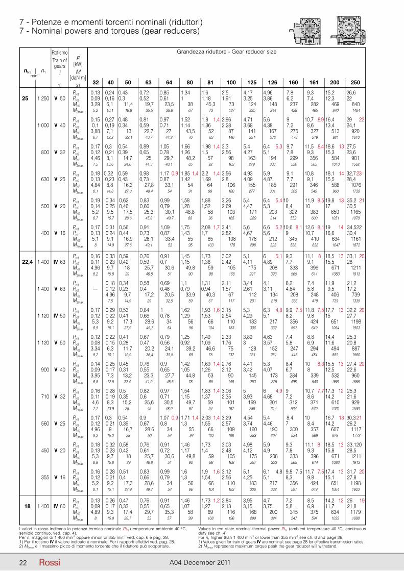
22 A04 December 2011
I valori in rosso indicano la potenza termica nominale PtN (temperatura ambiente 40 °C, servizio continuo, ved. cap. 4).Per n1 maggiori di 1 400 min-1 oppure minori di 355 min-1 ved. cap. 6 e pag. 28.1) Per il rotismo IV il valore indicato è nominale. Per i rapporti effettivi ved. pag. 28.2) M2max è il massimo picco di momento torcente che il riduttore può sopportare.
Values in red state nominal thermal power PtN (ambient temperature 40 °C, continuous duty see ch. 4).For n1 higher than 1 400 min-1 or lower than 355 min-1 see ch. 6 and page 28.1) Values given for train of gears IV are nominal; see page 28 for effective transmission ratios.2) M2max represents maximum torque peak the gear reducer will withstand.
7 - Potenze e momenti torcenti nominali (riduttori)7 - Nominal powers and torques (gear reducers)
Grandezza riduttore - Gear reducer size
32 40 50 63 64 80 81 100 125 126 160 161 200 250
nN2 n1min-1
RotismoTrain ofgears
i
1)
P[kW]M
[daN m]2)
PN1 0,13 0,24 0,43 0,72 0,85 1,34 1,6 2,5 4,17 4,96 07,8 09,3 15,2 26,6 25,5 1 250 V 50 PN2 0,09 0,16 0,3 0,52 0,61 1 1,18 1,91 3,25 3,86 06,2 07,4 12,3 22 MN2 3,29 6,1 11,4 19,7 23,5 38 45,3 73 124 148 237 282 469 840 M2max 5,2 10,1 19,8 35,5 38,6 67 73 127 225 244 428 465 840 1484
PN1 0,15 0,27 0,48 0,81 0,97 1,52 1,8 1,4 2,96 4,71 5,6 09 10,7 8,9 16,4 29 22 1 000 V 40 PN2 0,1 0,19 0,34 0,59 0,71 1,14 1,36 2,28 3,68 4,38 07,2 08,6 13,4 24,1 MN2 3,88 7,1 13 22,7 27 43,5 52 87 141 167 275 327 513 920 M2max 6,7 12,2 22,1 40,7 44,2 76 83 146 251 272 478 519 921 1610
PN1 0,17 0,30 0,54 0,89 1,05 1,66 1,98 1,4 3,3 5,4 6,4 5,3 09,7 11,5 8,4 18,6 13 27,5 800 V 32 PN2 0,12 0,21 0,39 0,65 0,78 1,26 1,5 2,56 4,27 5,1 07,8 09,3 15,3 23,6 MN2 4,46 8,1 14,7 25 29,7 48,2 57 98 163 194 299 356 584 901 M2max 7,5 13,6 24,6 44,3 48,1 85 92 162 279 303 520 565 1010 1562
PN1 0,18 0,320 0,59 0,98 1,17 0,9 1,85 1,4 2,2 1,4 3,56 4,93 5,9 09,1 10,8 18,1 14 32,7 23 630 V 25 PN2 0,13 0,23 0,43 0,73 0,87 1,42 1,69 2,8 4,09 4,87 07,7 09,1 15,5 28,4 MN2 4,84 8,8 16,3 27,8 33,1 54 64 106 155 185 291 346 588 1076 M2max 8,1 14,8 27,3 49,4 54 91 99 180 277 301 505 549 960 1739
PN1 0,19 0,34 0,62 0,83 0,99 1,58 1,88 3,26 5,4 6,4 5,4 10 11,9 8,5 19,8 13 35,2 21 500 V 20 PN2 0,14 0,25 0,46 0,66 0,79 1,28 1,52 2,69 4,47 5,3 28,4 10 17 30,5 MN2 5,2 9,5 17,5 25,3 30,1 48,8 58 103 171 203 322 383 650 1165 M2max 8,7 15,7 28,6 45,8 49,7 88 96 165 289 314 552 600 1051 1878
PN1 0,17 0,31 0,56 0,91 1,09 1,75 2,08 1,7 3,41 5,6 6,6 5,2 10,6 8,1 12,6 8,1 19 14 34,5 22 400 V 16 PN2 0,13 0,24 0,44 0,73 0,87 1,43 1,7 2,82 4,67 5,6 9 10,7 16,6 30,4 MN2 5,1 9,1 16,9 28,1 33,4 55 65 108 178 212 345 410 634 1161 M2max 8 14,9 27,6 49,1 53 95 103 178 298 323 588 638 1047 1872
PN1 0,16 0,33 0,59 0,76 0,91 1,45 1,73 3,02 5,1 6 5,1 9,3 11,1 8 18,5 13 33,1 20 22,4 1 400 IV 63 PN2 0,11 0,23 0,42 0,59 0,7 1,15 1,36 2,42 4,11 4,89 7,7 19,1 15,5 28 MN2 4,96 9,7 18 25,7 30,6 49,8 59 105 175 208 333 396 671 1211 M2max 8,2 15,8 29 46,8 51 90 98 168 297 323 565 614 1083 1913
PN1 0,18 0,34 0,58 0,69 1,1 1,31 2,11 3,44 4,1 6,2 7,4 11,9 21,2 1 400 V 63 PN2 — 0,12 0,23 0,4 0,48 0,79 0,94 1,57 2,61 3,11 4,84 5,8 9,5 17,2 MN2 4,96 9,7 17,2 20,5 33,9 40,3 67 112 134 208 248 406 739 M2max 7,5 14,9 29 32,5 59 67 117 201 219 386 419 739 1339
PN1 0,17 0,29 0,53 0,84 1 1,62 1,93 1,6 3,15 5,3 6,3 4,8 9,9 7,5 11,8 7,5 17,7 13 32,2 20 1 120 IV 50 PN2 0,12 0,22 0,41 0,66 0,78 1,29 1,53 2,54 4,29 5,1 8,2 9,8 15 27,7 MN2 5,3 9,2 17,3 28,6 34 56 66 110 183 217 356 424 651 1198 M2max 8,9 15,1 27,9 49,7 54 96 104 183 306 332 597 649 1064 1903
PN1 0,12 0,22 0,41 0,67 0,79 1,25 1,49 2,33 3,89 4,63 7,4 8,8 14,4 25,3 1 120 V 50 PN2 0,08 0,15 0,28 0,47 0,56 0,92 1,09 1,76 3 3,57 5,8 6,9 11,6 20,8 MN2 3,34 6,3 11,7 20,2 24,1 39,2 46,6 75 128 152 247 294 494 887 M2max 5,2 10,1 19,9 36,4 39,5 69 75 132 231 251 446 484 869 1560
PN1 0,14 0,25 0,45 0,76 0,9 1,42 1,69 1,4 2,76 4,41 5,3 8,4 10 8,3 15,5 13 27,4 20 900 V 40 PN2 0,09 0,17 0,31 0,55 0,65 1,05 1,26 2,12 3,42 4,07 6,7 8 12,5 22,6 MN2 3,95 7,3 13,2 23,3 27,7 44,8 53 90 145 173 284 339 532 960 M2max 6,8 12,5 22,4 41,9 45,5 78 85 148 253 275 498 540 966 1666
PN1 0,16 0,28 0,5 0,82 0,97 1,54 1,83 1,4 3,06 5 6 4,9 9 10,7 7,7 17,3 12 25,3 710 V 32 PN2 0,11 0,19 0,35 0,6 0,71 1,15 1,37 2,35 3,93 4,68 7,2 8,6 14,2 21,6 MN2 4,6 8,3 15,2 25,6 30,5 49,7 59 101 169 201 312 371 610 929 M2max 7,7 13,9 25 45 48,9 87 94 167 289 314 534 579 1031 1593
PN1 0,17 0,30 0,54 0,9 1,07 0,9 1,71 1,4 2,03 1,4 3,29 4,54 5,4 08,4 10 16,7 13 30,3 21 560 V 25 PN2 0,12 0,21 0,39 0,67 0,8 1,3 1,55 2,57 3,74 4,46 7 8,4 14,2 26,2 MN2 4,96 9 16,7 28,6 34 55 66 109 160 190 300 357 607 1117 M2max 8,2 15,2 28 50 54 94 102 186 283 307 524 569 978 1773
PN1 0,18 0,32 0,58 0,76 0,91 1,46 1,73 3,03 4,98 5,9 9,3 11,1 8 18,5 13 33,1 20 450 V 20 PN2 0,13 0,23 0,42 0,61 0,72 1,17 1,4 2,48 4,12 4,9 7,8 9,3 15,8 28,5 MN2 5,3 9,7 18 25,7 30,6 49,8 59 105 175 208 333 396 671 1211 M2max 8,9 15,8 29 46,8 51 90 98 168 297 323 565 614 1083 1913
PN1 0,16 0,28 0,51 0,83 0,99 1,6 1,9 1,6 3,12 5,1 6,1 4,8 9,8 7,5 11,7 7,5 17,4 13 31,7 20 355 V 16 PN2 0,12 0,21 0,4 0,66 0,79 1,3 1,54 2,56 4,25 5,1 8,3 9,8 15,1 27,8 MN2 5,2 9,2 17,3 28,6 34 56 66 110 183 217 356 424 651 1198 M2max 8,1 15,1 27,9 49,7 54 96 104 183 306 332 597 649 1064 1903
PN1 0,13 0,26 0,47 0,76 0,91 1,46 1,73 1,2 2,84 3,95 4,7 7,2 8,5 14,2 12 26 19 18 1 400 IV 80 PN2 0,09 0,17 0,33 0,55 0,65 1,07 1,27 2,13 3,15 3,75 5,8 6,9 11,7 21,8 MN2 4,89 9,3 17,4 29,7 35,3 58 69 116 168 200 315 375 634 1179 M2max 8 15,9 28,7 53 57 99 108 196 299 324 547 594 1039 1888
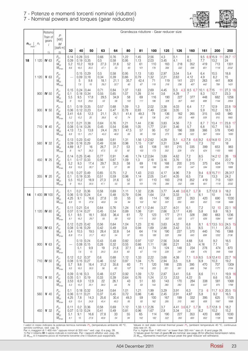
23A04 December 2011
I valori in rosso indicano la potenza termica nominale PtN (temperatura ambiente 40 °C, servizio continuo, ved. cap. 4).Per n1 maggiori di 1 400 min-1 oppure minori di 355 min-1 ved. cap. 6 e pag. 28.1) Per il rotismo IV il valore indicato è nominale. Per i rapporti effettivi ved. pag. 28.2) M2max è il massimo picco di momento torcente che il riduttore può sopportare.
Values in red state nominal thermal power PtN (ambient temperature 40 °C, continuous duty see ch. 4).For n1 higher than 1 400 min-1 or lower than 355 min-1 see ch. 6 and page 28.1) Values given for train of gears IV are nominal; see page 28 for effective transmission ratios.2) M2max represents maximum torque peak the gear reducer will withstand.
7 - Potenze e momenti torcenti nominali (riduttori)7 - Nominal powers and torques (gear reducers)
Grandezza riduttore - Gear reducer size
32 40 50 63 64 80 81 100 125 126 160 161 200 250
nN2 n1min-1
RotismoTrain ofgears
i
1)
P[kW]M
[daN m]2)
PN1 0,14 0,28 0,5 0,66 0,76 1,22 1,45 2,56 4,3 5,1 8 9,5 6,9 15,9 11 28,7 17 18,5 1 120 IV 63 PN2 0,09 0,19 0,35 0,5 0,58 0,95 1,13 2,03 3,45 4,1 6,5 7,7 13,2 24 MN2 5,2 10,2 18,9 27,3 31,6 52 61 110 183 218 352 419 713 1301 M2max 8,6 16,5 30,5 47,1 53 93 101 176 306 332 599 651 1118 2032
PN1 0,15 0,29 0,5 0,58 0,95 1,13 1,83 2,97 3,54 5,4 6,4 10,5 18,8 1 120 V 63 PN2 — 0,09 0,18 0,34 0,39 0,66 0,79 1,32 2,21 2,63 4,12 4,9 8,2 15 MN2 5 9,8 18,1 21,1 35,7 42,4 71 119 141 221 263 441 808 M2max 7,6 15 29,2 32,7 60 67 118 218 236 407 442 789 1431
PN1 0,15 0,24 0,44 0,71 0,84 1,37 1,63 2,69 4,45 5,3 4,3 8,5 6,7 10,1 6,7 15 11 27,3 18 900 IV 50 PN2 0,10 0,18 0,34 0,55 0,65 1,07 1,28 2,14 3,6 4,28 7 8,3 12,7 23,3 MN2 5,5 9,5 17,8 29,5 34,9 58 69 116 190 227 377 448 682 1256 M2max 9 15,9 29,6 53 58 103 111 196 328 357 643 699 1144 2054
PN1 0,10 0,19 0,35 0,57 0,68 1,09 1,3 2,02 3,38 4,03 6,4 7,7 12,9 22,8 19 900 V 50 PN2 0,06 0,12 0,23 0,4 0,47 0,78 0,93 1,49 2,56 3,05 5 5,9 10,2 18,5 MN2 3,41 6,6 12,3 21,1 25,1 41,4 49,3 79 136 162 265 315 543 980 M2max 5,2 10,2 20 38,6 42 74 80 136 242 263 469 509 915 1665
PN1 0,12 0,21 0,38 0,64 0,76 1,21 1,44 2,36 3,83 4,56 7,3 8,7 7 13,4 11 23,8 17 710 V 40 PN2 0,08 0,14 0,26 0,45 0,54 0,88 1,05 1,77 2,91 3,46 5,7 6,8 10,7 19,3 MN2 4,13 7,5 13,8 24,4 29,1 47,5 57 95 157 186 308 366 578 1040 M2max 6,8 13,1 23,7 43,2 46,9 83 90 158 273 296 522 567 1004 1830
PN1 0,13 0,23 0,42 0,68 0,81 1,31 1,56 1,2 2,62 4,29 5,1 4,2 7,8 6,6 9,2 6,6 14,8 10 21,3 560 V 32 PN2 0,09 0,16 0,29 0,49 0,58 0,96 1,15 1,97 3,31 3,94 6,1 7,3 12 18 MN2 4,89 8,7 16 26,7 31,7 53 63 108 181 215 335 399 653 983 M2max 8 14,7 26,3 47,5 52 92 100 173 302 329 574 624 1100 1680
PN1 0,14 0,25 0,46 0,77 0,91 1,46 1,74 1,2 2,84 3,89 4,62 7,2 8,5 14,2 12 26 19 450 V 25 PN2 0,10 0,17 0,33 0,56 0,67 1,09 1,3 2,18 3,16 3,76 5,9 7,1 12 22,2 MN2 5,2 9,3 17,4 29,7 35,3 58 69 116 168 200 315 375 634 1179 M2max 8,6 15,9 28,7 53 57 99 108 196 299 324 547 594 1039 1888
PN1 0,15 0,27 0,49 0,65 0,75 1,2 1,43 2,53 4,17 4,96 7,9 9,4 6,9 15,7 11 28,3 17 355 V 20 PN2 0,10 0,19 0,35 0,51 0,59 0,96 1,14 2,05 3,41 4,05 6,5 7,8 13,3 24,2 MN2 5,5 10,2 18,9 27,3 31,6 52 61 110 183 218 352 419 713 1301 M2max 9 16,5 30,5 47,1 53 93 101 176 306 332 599 651 1118 2032
PN1 0,10 0,20 0,36 0,58 0,69 1,11 1,32 2,26 3,77 4,48 3,6 6,7 5,7 8 5,7 12,8 9 18,2 14 1 400 IV 100 PN2 0,06 0,13 0,24 0,4 0,48 0,79 0,94 1,64 2,8 3,33 5,1 6,1 10 14,9 MN2 4,25 9,1 16,6 27,8 33 55 65 114 190 227 353 420 690 1030 M2max 6,9 15 27,6 49,8 54 94 102 182 322 350 600 652 1138 1686
PN1 0,11 0,21 0,4 0,64 0,76 1,24 1,47 1,1 2,44 3,37 4,01 6,1 7,2 12 10 22,1 16 1 120 IV 80 PN2 0,07 0,14 0,27 0,45 0,54 0,89 1,06 1,81 2,66 3,17 4,85 5,8 09,8 18,3 MN2 5,1 9,5 18,1 30,6 36,4 61 72 123 177 211 328 390 663 1236 M2max 8,1 16,2 29,7 55 59 102 111 202 302 333 577 626 1084 1997
PN1 0,12 0,23 0,42 0,56 0,64 1,04 1,23 2,16 3,63 4,32 6,8 8,1 6,1 13,5 9,5 24,5 15 900 IV 63 PN2 0,08 0,16 0,29 0,42 0,49 0,8 0,94 1,69 2,88 3,42 5,5 6,5 11,1 20,3 MN2 5,4 10,5 19,5 28,4 32,8 54 64 114 190 227 370 440 745 1368 M2max 8,8 17,4 31,7 48,3 54 97 105 188 328 356 643 699 1202 2136
PN1 0,13 0,24 0,43 0,49 0,82 0,97 1,57 2,56 3,04 4,68 5,6 09,2 16,5 900 V 63 PN2 — 0,08 0,15 0,28 0,32 0,55 0,66 1,11 1,86 2,21 3,5 4,16 07,1 13 MN2 5,1 9,9 19 21,6 37,1 44,1 74 124 148 234 278 474 870 M2max 7,6 15 29,3 32,8 60 67 119 228 247 438 476 848 1568
PN1 0,12 0,2 0,37 0,6 0,68 1,12 1,33 2,22 3,68 4,38 7,1 5,9 8,5 5,9 12,4 10 22,7 16 710 IV 50 PN2 0,08 0,15 0,27 0,46 0,52 0,87 1,04 1,75 2,94 3,5 5,8 6,9 10,3 19,2 MN2 5,7 9,8 18,4 31,2 35,6 60 71 120 198 235 395 470 707 1309 M2max 9,5 16,5 30,5 56 60 107 116 205 351 381 689 748 1171 2154
PN1 0,09 0,16 0,3 0,48 0,57 0,92 1,09 1,72 2,87 3,41 5,6 6,6 11,1 19,9 16 710 V 50 PN2 0,05 0,10 0,19 0,33 0,39 0,64 0,76 1,24 2,13 2,53 4,22 5 28,6 15,9 MN2 3,53 6,9 12,9 22 26,1 43 51 83 143 170 284 338 581 1068 M2max 5,3 10,2 20,1 39,3 44 76 83 144 260 282 504 547 975 1789
PN1 0,10 0,18 0,32 0,54 0,64 1,01 1,21 1,99 3,29 3,91 6,3 7,5 6 11,7 9,3 20,5 15 560 V 40 PN2 0,06 0,11 0,21 0,37 0,45 0,72 0,86 1,46 2,45 2,91 4,87 5,8 29,2 16,5 MN2 4,25 7,8 14,3 25,6 30,4 49,3 59 100 167 199 332 395 625 1125 M2max 6,9 13,4 24,8 45,4 49,3 85 93 162 285 310 560 608 1067 1898
PN1 0,11 0,2 0,36 0,58 0,69 1,12 1,33 1,1 2,26 3,7 4,41 3,6 6,7 5,7 8 5,7 12,8 9 18,2 450 V 32 PN2 0,07 0,13 0,24 0,41 0,49 0,81 0,96 1,67 2,8 3,34 5,2 6,2 10,2 15,2 MN2 5,1 9,1 16,6 27,8 33 55 65 114 190 227 353 420 690 1030 M2max 8,1 15 27,6 49,8 54 94 102 182 322 350 600 652 1138 1686
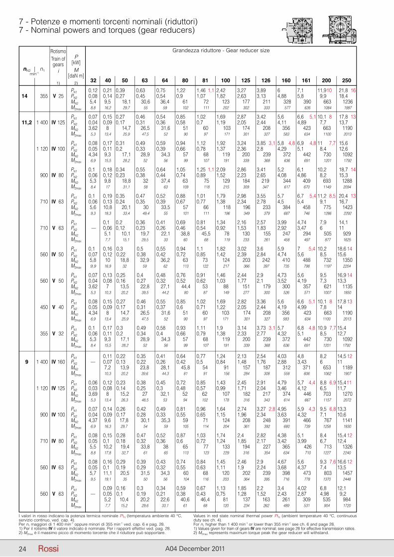
24 A04 December 2011
I valori in rosso indicano la potenza termica nominale PtN (temperatura ambiente 40 °C, servizio continuo, ved. cap. 4).Per n1 maggiori di 1 400 min-1 oppure minori di 355 min-1 ved. cap. 6 e pag. 28.1) Per il rotismo IV il valore indicato è nominale. Per i rapporti effettivi ved. pag. 28.2) M2max è il massimo picco di momento torcente che il riduttore può sopportare.
Values in red state nominal thermal power PtN (ambient temperature 40 °C, continuous duty see ch. 4).For n1 higher than 1 400 min-1 or lower than 355 min-1 see ch. 6 and page 28.1) Values given for train of gears IV are nominal; see page 28 for effective transmission ratios.2) M2max represents maximum torque peak the gear reducer will withstand.
7 - Potenze e momenti torcenti nominali (riduttori)7 - Nominal powers and torques (gear reducers)
Grandezza riduttore - Gear reducer size
32 40 50 63 64 80 81 100 125 126 160 161 200 250
nN2 n1min-1
RotismoTrain ofgears
i
1)
P[kW]M
[daN m]2)
PN1 0,12 0,21 0,39 0,63 0,75 1,22 1,46 1,1 2,42 3,27 3,89 6 7,1 11,9 10 21,8 16 14,5 355 V 25 PN2 0,08 0,14 0,27 0,45 0,54 0,9 1,07 1,82 2,63 3,13 4,88 5,8 29,9 18,4 MN2 5,4 9,5 18,1 30,6 36,4 61 72 123 177 211 328 390 663 1236 M2max 8,8 16,2 29,7 55 59 102 111 202 302 333 577 626 1084 1997
PN1 0,07 0,15 0,27 0,46 0,54 0,85 1,02 1,69 2,87 3,42 5,6 6,6 5,1 10,1 8 17,8 13 11,2 1 400 IV 125 PN2 0,04 0,09 0,17 0,31 0,36 0,58 0,7 1,19 2,05 2,44 4,11 4,89 27,7 13,7 MN2 3,62 8 14,7 26,5 31,6 51 60 103 174 208 356 423 663 1190 M2max 5,3 13,4 25,9 47,5 52 90 97 171 301 327 583 634 1100 2013
PN1 0,08 0,17 0,31 0,49 0,59 0,94 1,12 1,92 3,24 3,85 3,1 5,8 4,8 6,9 4,8 11 7,7 15,6 1 120 IV 100 PN2 0,05 0,11 0,2 0,33 0,39 0,66 0,78 1,37 2,36 2,8 4,29 5,1 28,4 12,6 MN2 4,34 9,3 17,1 28,9 34,3 57 68 119 200 239 372 442 730 1092 M2max 6,9 15,5 28,2 52 56 99 107 191 339 368 636 691 1201 1792
PN1 0,10 0,18 0,34 0,55 0,64 1,05 1,25 1,1 2,09 2,86 3,41 5,2 6,1 10,2 18,7 14 900 IV 80 PN2 0,06 0,12 0,23 0,38 0,44 0,74 0,89 1,52 2,23 2,65 4,08 4,86 28,2 15,3 MN2 5,3 9,8 18,8 32 37,4 63 75 129 184 219 344 409 693 1288 M2max 8,4 17 31,1 58 63 109 118 215 309 347 617 670 1149 2094
PN1 0,10 0,19 0,35 0,47 0,52 0,88 1,01 1,79 2,98 3,55 5,7 6,7 5,4 11,2 8,5 20,4 13 710 IV 63 PN2 0,06 0,13 0,24 0,35 0,39 0,67 0,77 1,38 2,34 2,78 4,5 5,4 29,1 16,7 MN2 5,6 10,8 20,1 30 33,5 57 66 118 196 233 384 458 775 1423 M2max 9,3 18,3 33,4 49,4 55 101 111 196 349 379 687 746 1286 2292
PN1 0,10 0,2 0,36 0,41 0,69 0,81 1,34 2,16 2,57 3,99 4,74 27,9 14,1 710 V 63 PN2 — 0,06 0,12 0,23 0,26 0,46 0,54 0,92 1,53 1,83 2,92 3,47 26 11 MN2 5,1 10,1 19,7 22,1 38,8 45,5 78 130 155 247 294 505 929 M2max 7,7 15,1 29,5 33 60 68 119 233 261 458 497 877 1625
PN1 0,10 0,16 0,3 0,5 0,55 0,94 1,1 1,82 3,02 3,6 5,9 7 5,4 10,2 18,6 14 560 IV 50 PN2 0,07 0,12 0,22 0,38 0,42 0,72 0,85 1,42 2,39 2,84 4,74 5,6 8,5 15,6 MN2 5,8 10 18,8 32,9 36,2 63 73 124 203 242 410 488 732 1350 M2max 9,9 16,9 32 59 62 113 122 217 366 397 735 798 1197 2204
PN1 0,07 0,13 0,25 0,4 0,48 0,76 0,91 1,46 2,44 2,9 4,73 5,6 9,5 16,9 14 560 V 50 PN2 0,04 0,08 0,16 0,27 0,32 0,52 0,62 1,03 1,77 2,1 3,52 4,19 7,3 13,3 MN2 3,62 7 13,5 22,8 27,1 44,4 53 88 151 179 300 357 621 1135 M2max 5,3 10,3 20,2 39,5 44,2 80 87 149 277 300 526 571 1007 1850
PN1 0,08 0,15 0,27 0,46 0,55 0,85 1,02 1,69 2,82 3,36 5,6 6,6 5,1 10,1 8 17,8 13 450 V 40 PN2 0,05 0,09 0,17 0,31 0,37 0,6 0,71 1,22 2,05 2,44 4,19 4,99 7,8 14 MN2 4,34 8 14,7 26,5 31,6 51 60 103 174 208 356 423 663 1190 M2max 6,9 13,4 25,9 47,5 52 90 97 171 301 327 583 634 1100 2013
PN1 0,10 0,17 0,3 0,49 0,58 0,93 1,11 1,9 3,14 3,73 3,1 5,7 6,8 4,8 10,9 7,7 15,4 355 V 32 PN2 0,06 0,11 0,2 0,34 0,4 0,66 0,79 1,38 2,33 2,77 4,32 5,1 8,5 12,7 MN2 5,3 9,3 17,1 28,9 34,3 57 68 119 200 239 372 442 730 1092 M2max 8,4 15,5 28,2 52 56 99 107 191 339 368 636 691 1201 1792
PN1 0,11 0,22 0,35 0,41 0,64 0,77 1,24 2,13 2,54 4,03 4,8 8,2 14,5 12 9 1 400 IV 160 PN2 — 0,07 0,13 0,22 0,26 0,42 0,5 0,84 1,48 1,76 2,88 3,43 6 11 MN2 7,2 13,9 23,8 28,1 45,8 54 91 157 187 312 371 653 1189 M2max 10,3 20,2 39,6 44,3 81 91 156 284 308 558 606 1062 1907
PN1 0,06 0,12 0,23 0,38 0,45 0,72 0,85 1,43 2,45 2,91 4,79 5,7 4,4 8,8 6,9 15,411 1 120 IV 125 PN2 0,03 0,08 0,14 0,25 0,3 0,48 0,57 0,99 1,71 2,04 3,46 4,12 6,5 11,7 MN2 3,69 8 15,2 27 32,1 52 62 107 182 217 374 446 703 1270 M2max 5,3 13,4 26,3 48,5 53 94 102 178 316 343 614 667 1157 2072
PN1 0,07 0,14 0,26 0,42 0,49 0,81 0,96 1,64 2,74 3,27 2,8 4,95 5,9 4,3 9,5 6,8 13,3 900 IV 100 PN2 0,04 0,09 0,17 0,28 0,33 0,55 0,65 1,15 1,96 2,34 3,63 4,32 7,1 10,6 MN2 4,37 9,6 17,8 30,1 35,3 59 71 124 208 248 391 466 767 1141 M2max 6,9 16,3 29,7 54 59 105 114 204 361 392 680 739 1258 1830
PN1 0,08 0,15 0,28 0,47 0,52 0,87 1,03 1,74 2,4 2,82 4,38 5,1 8,4 15,4 12 710 IV 80 PN2 0,05 0,10 0,18 0,32 0,36 0,6 0,72 1,24 1,85 2,17 3,42 3,99 6,7 12,4 MN2 5,5 10,2 19,4 33,8 38 65 77 133 194 227 365 426 713 1326 M2max 8,8 17,8 32,7 61 65 113 123 229 316 354 634 710 1227 2240
PN1 0,08 0,16 0,29 0,39 0,43 0,74 0,84 1,45 2,46 2,9 4,67 5,6 9,3 7,6 16,6 12 560 IV 63 PN2 0,05 0,10 0,19 0,29 0,32 0,55 0,63 1,11 1,9 2,24 3,68 4,37 7,4 13,5 MN2 5,7 11,1 20,5 31,5 34,3 60 68 120 202 239 398 473 803 1457 M2max 9,5 19,1 35 50 56 104 116 203 364 395 716 778 1370 2448
PN1 0,09 0,16 0,3 0,34 0,59 0,67 1,13 1,85 2,2 3,4 4,02 6,8 12,1 560 V 63 PN2 — 0,05 0,1 0,19 0,21 0,38 0,43 0,75 1,28 1,52 2,43 2,87 4,98 9,2 MN2 5,2 10,4 20,2 22,6 40,6 46,4 81 137 163 261 309 535 984 M2max 7,7 15,2 29,6 33,1 61 68 120 234 262 489 531 904 1720
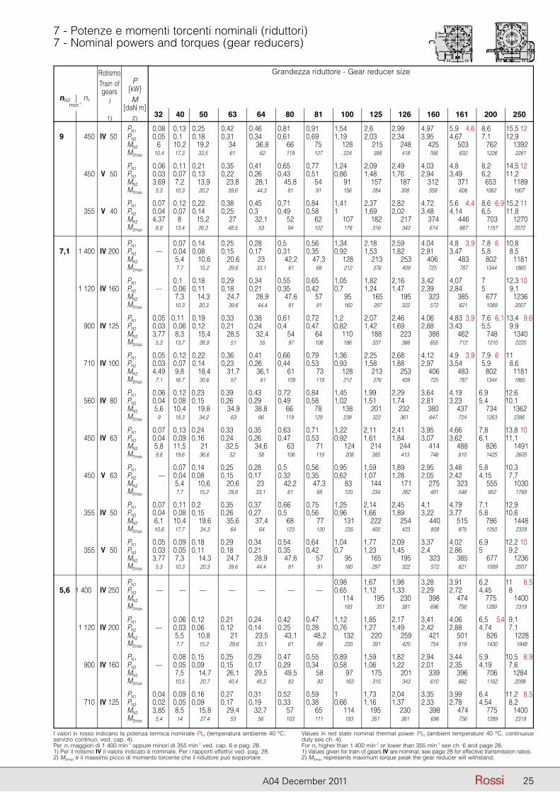
25A04 December 2011
I valori in rosso indicano la potenza termica nominale PtN (temperatura ambiente 40 °C, servizio continuo, ved. cap. 4).Per n1 maggiori di 1 400 min-1 oppure minori di 355 min-1 ved. cap. 6 e pag. 28.1) Per il rotismo IV il valore indicato è nominale. Per i rapporti effettivi ved. pag. 28.2) M2max è il massimo picco di momento torcente che il riduttore può sopportare.
Values in red state nominal thermal power PtN (ambient temperature 40 °C, continuous duty see ch. 4).For n1 higher than 1 400 min-1 or lower than 355 min-1 see ch. 6 and page 28.1) Values given for train of gears IV are nominal; see page 28 for effective transmission ratios.2) M2max represents maximum torque peak the gear reducer will withstand.
7 - Potenze e momenti torcenti nominali (riduttori)7 - Nominal powers and torques (gear reducers)
Grandezza riduttore - Gear reducer size
32 40 50 63 64 80 81 100 125 126 160 161 200 250
nN2 n1min-1
RotismoTrain ofgears
i
1)
P[kW]M
[daN m]2)
PN1 0,08 0,13 0,25 0,42 0,46 0,81 0,91 1,54 2,6 2,99 4,97 5,9 4,6 8,6 15,5 12 9,5 450 IV 50 PN2 0,05 0,10 0,18 0,31 0,34 0,61 0,69 1,19 2,03 2,34 3,95 4,67 7,1 12,9 MN2 6 10,2 19,2 34 36,8 66 75 128 215 248 425 503 762 1392 M2max 10,4 17,3 33,5 61 62 119 127 224 388 418 766 832 1226 2281
PN1 0,06 0,11 0,21 0,35 0,41 0,65 0,77 1,24 2,09 2,49 4,03 4,8 8,2 14,5 12 450 V 50 PN2 0,03 0,07 0,13 0,22 0,26 0,43 0,51 0,86 1,48 1,76 2,94 3,49 6,2 11,2 MN2 3,69 7,2 13,9 23,8 28,1 45,8 54 91 157 187 312 371 653 1189 M2max 5,3 10,3 20,2 39,6 44,3 81 91 156 284 308 558 606 1062 1907
PN1 0,07 0,12 0,22 0,38 0,45 0,71 0,84 1,41 2,37 2,82 4,72 5,6 4,4 8,6 6,9 15,2 11 355 V 40 PN2 0,04 0,07 0,14 0,25 0,3 0,49 0,58 1 1,69 2,02 3,48 4,14 6,5 11,8 MN2 4,37 8 15,2 27 32,1 52 62 107 182 217 374 446 703 1270 M2max 6,9 13,4 26,3 48,5 53 94 102 178 316 343 614 667 1157 2072
PN1 0,07 0,14 0,25 0,28 0,5 0,56 1,34 2,18 2,59 4,04 4,8 3,9 7,8 6 10,8 7,1 1 400 IV 200 PN2 — 0,04 0,08 0,15 0,17 0,31 0,35 0,92 1,53 1,82 2,91 3,47 5,8 8,5 MN2 5,4 10,6 20,6 23 42,2 47,3 128 213 253 406 483 802 1181 M2max 7,7 15,2 29,6 33,1 61 68 212 376 409 725 787 1344 1865
PN1 0,10 0,18 0,29 0,34 0,55 0,65 1,05 1,82 2,16 3,42 4,07 7 12,3 10 1 120 IV 160 PN2 — 0,06 0,11 0,18 0,21 0,35 0,42 0,7 1,24 1,47 2,39 2,84 5 9,1 MN2 7,3 14,3 24,7 28,9 47,6 57 95 165 195 323 385 677 1236 M2max 10,3 20,3 39,6 44,4 81 91 160 297 322 572 621 1089 2007
PN1 0,05 0,110 0,19 0,33 0,38 0,61 0,72 1,2 2,07 2,46 4,06 4,83 3,9 7,6 6,1 13,4 9,6 900 IV 125 PN2 0,03 0,06 0,12 0,21 0,24 0,4 0,47 0,82 1,42 1,69 2,88 3,43 5,5 9,9 MN2 3,77 8,3 15,4 28,5 32,4 54 64 110 188 223 388 462 748 1340 M2max 5,3 13,7 26,9 51 55 97 106 186 337 366 655 712 1210 2220
PN1 0,05 0,12 0,22 0,36 0,41 0,66 0,79 1,36 2,25 2,68 4,12 4,9 3,9 7,9 6 11 710 IV 100 PN2 0,03 0,07 0,14 0,23 0,26 0,44 0,53 0,93 1,58 1,88 2,97 3,54 5,9 8,6 MN2 4,49 9,8 18,4 31,7 36,1 61 73 128 213 253 406 483 802 1181 M2max 7,1 16,7 30,6 57 61 109 119 212 376 409 725 787 1344 1865
PN1 0,06 0,12 0,23 0,39 0,43 0,72 0,84 1,45 1,99 2,29 3,64 4,19 6,9 12,6 560 IV 80 PN2 0,04 0,08 0,15 0,26 0,29 0,49 0,58 1,02 1,51 1,74 2,81 3,23 5,4 10,1 MN2 5,6 10,4 19,8 34,9 38,8 66 78 138 201 232 380 437 734 1362 M2max 9 18,3 34,2 63 66 119 129 238 322 361 647 724 1263 2386
PN1 0,07 0,13 0,24 0,33 0,35 0,63 0,71 1,22 2,11 2,41 3,95 4,66 7,8 13,8 10 450 IV 63 PN2 0,04 0,09 0,16 0,24 0,26 0,47 0,53 0,92 1,61 1,84 3,07 3,62 6,1 11,1 MN2 5,8 11,5 21 32,5 34,6 63 71 124 214 244 414 488 826 1491 M2max 9,8 19,6 36,6 52 58 106 119 208 385 413 746 810 1425 2605
PN1 0,07 0,14 0,25 0,28 0,5 0,56 0,95 1,59 1,89 2,95 3,48 5,8 10,3 450 V 63 PN2 — 0,04 0,08 0,15 0,17 0,32 0,35 0,62 1,07 1,28 2,05 2,42 4,15 7,7 MN2 5,4 10,6 20,6 23 42,2 47,3 83 144 171 275 323 555 1030 M2max 7,7 15,2 29,6 33,1 61 68 120 234 262 491 548 952 1769
PN1 0,07 0,11 0,2 0,35 0,37 0,66 0,75 1,25 2,14 2,45 4,1 4,79 7,1 12,9 355 IV 50 PN2 0,04 0,08 0,15 0,26 0,27 0,5 0,56 0,96 1,66 1,89 3,22 3,77 5,8 10,6 MN2 6,1 10,4 19,6 35,6 37,4 68 77 131 222 254 440 515 786 1448 M2max 10,6 17,7 34,3 64 64 123 130 235 400 423 809 875 1250 2329
PN1 0,05 0,09 0,18 0,29 0,34 0,54 0,64 1,04 1,77 2,09 3,37 4,02 6,9 12,2 10 355 V 50 PN2 0,03 0,05 0,11 0,18 0,21 0,35 0,42 0,7 1,23 1,45 2,4 2,86 5 9,2 MN2 3,77 7,3 14,3 24,7 28,9 47,6 57 95 165 195 323 385 677 1236 M2max 5,3 10,3 20,3 39,6 44,4 81 91 160 297 322 572 621 1089 2007
PN1 0,98 1,67 1,98 3,28 3,91 6,2 11 8,5 5,6 1 400 IV 250 PN2 — — — — — — — 0,65 1,12 1,33 2,29 2,72 4,45 8 MN2 114 195 230 398 474 775 1400 M2max 193 351 381 696 756 1289 2319
PN1 0,06 0,12 0,21 0,24 0,42 0,47 1,12 1,85 2,17 3,41 4,06 6,5 5,4 9,1 1 120 IV 200 PN2 — 0,03 0,06 0,12 0,14 0,25 0,28 0,76 1,27 1,49 2,42 2,88 4,74 7,1 MN2 5,5 10,8 21 23,5 43,1 48,2 132 220 259 421 501 826 1228 M2max 7,7 15,2 29,6 33,1 61 68 220 391 425 754 819 1430 1948
PN1 0,08 0,15 0,25 0,29 0,47 0,55 0,89 1,59 1,82 2,94 3,44 5,9 10,5 8,9 900 IV 160 PN2 — 0,05 0,09 0,15 0,17 0,29 0,34 0,58 1,06 1,22 2,01 2,35 4,19 7,6 MN2 7,5 14,7 26,1 29,5 49,5 58 97 175 201 339 396 706 1284 M2max 10,5 20,7 40,4 45,3 83 93 163 315 343 610 662 1162 2098
PN1 0,04 0,09 0,16 0,27 0,31 0,52 0,59 1 1,73 2,04 3,35 3,99 6,4 11,2 8,5 710 IV 125 PN2 0,02 0,05 0,09 0,17 0,19 0,33 0,38 0,66 1,16 1,37 2,33 2,78 4,54 8,2 MN2 3,85 8,5 15,8 29,4 32,7 57 65 114 195 230 398 474 775 1400 M2max 5,4 14 27,4 53 56 103 111 193 351 381 696 756 1289 2319
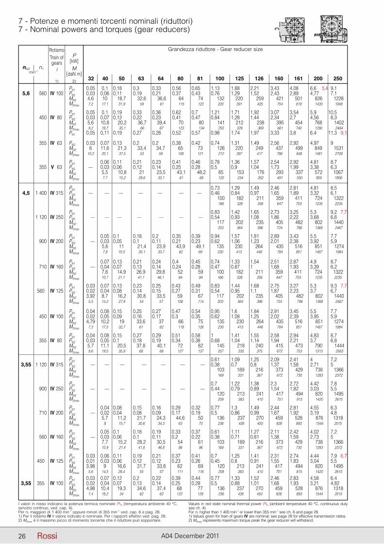
26 A04 December 2011
I valori in rosso indicano la potenza termica nominale PtN (temperatura ambiente 40 °C, servizio continuo, ved. cap. 4).Per n1 maggiori di 1 400 min-1 oppure minori di 355 min-1 ved. cap. 6 e pag. 28.1) Per il rotismo IV il valore indicato è nominale. Per i rapporti effettivi ved. pag. 28.2) M2max è il massimo picco di momento torcente che il riduttore può sopportare.
Values in red state nominal thermal power PtN (ambient temperature 40 °C, continuous duty see ch. 4).For n1 higher than 1 400 min-1 or lower than 355 min-1 see ch. 6 and page 28.1) Values given for train of gears IV are nominal; see page 28 for effective transmission ratios.2) M2max represents maximum torque peak the gear reducer will withstand.
7 - Potenze e momenti torcenti nominali (riduttori)7 - Nominal powers and torques (gear reducers)
Grandezza riduttore - Gear reducer size
32 40 50 63 64 80 81 100 125 126 160 161 200 250
nN2 n1min-1
RotismoTrain ofgears
i
1)
P[kW]M
[daN m]2)
PN1 0,05 0,1 0,18 0,3 0,33 0,56 0,65 1,13 1,88 2,21 3,43 4,08 6,6 5,4 9,1 5,6 560 IV 100 PN2 0,03 0,06 0,11 0,19 0,21 0,37 0,43 0,76 1,29 1,52 2,43 2,89 4,77 7,1 MN2 4,6 10 18,7 32,6 36,6 64 74 132 220 259 421 501 826 1228 M2max 7,2 17,1 31,9 59 61 115 123 220 391 425 754 819 1430 1948
PN1 0,05 0,1 0,19 0,33 0,36 0,62 0,7 1,21 1,71 1,92 3,07 3,54 5,9 10,5 450 IV 80 PN2 0,03 0,07 0,12 0,22 0,23 0,41 0,47 0,84 1,28 1,44 2,34 2,7 4,56 8,3 MN2 5,6 10,8 20,2 36,7 39,4 70 80 141 212 238 395 454 768 1402 M2max 9,2 18,7 35,1 66 67 123 134 250 329 369 661 740 1290 2484 PN1 0,05 0,11 0,19 0,27 0,28 0,52 0,57 0,98 1,74 1,97 3,33 3,8 6,4 11,3 9,1
355 IV 63 PN2 0,03 0,07 0,13 0,2 0,2 0,38 0,42 0,74 1,31 1,49 2,56 2,92 4,97 9 MN2 6 11,6 21,3 33,4 34,7 65 73 126 220 249 437 499 849 1531 M2max 10,2 20,1 37,5 53 59 108 121 212 397 417 786 848 1481 2709
PN1 0,06 0,11 0,21 0,23 0,41 0,46 0,78 1,36 1,57 2,54 2,92 4,81 8,7 355 V 63 PN2 — 0,03 0,06 0,12 0,14 0,25 0,28 0,5 0,9 1,04 1,73 1,99 3,38 6,3 MN2 5,5 10,8 21 23,5 43,1 48,2 85 153 176 293 337 572 1067 M2max 7,7 15,2 29,6 33,1 61 68 120 234 262 491 550 959 1856
PN1 0,73 1,29 1,49 2,46 2,81 4,81 8,5 4,5 1 400 IV 315 PN2 — — — — — — — 0,46 0,84 0,97 1,65 1,89 3,32 6,1 MN2 100 182 211 359 411 724 1322 M2max 166 326 356 647 703 1235 2235
PN1 0,83 1,42 1,65 2,73 3,25 5,3 9,2 7,7 1 120 IV 250 PN2 — — — — — — — 0,54 0,93 1,08 1,86 2,22 3,68 6,6 MN2 117 202 235 405 482 802 1440 M2max 203 364 396 724 786 1368 2467
PN1 0,05 0,1 0,18 0,2 0,35 0,39 0,94 1,57 1,81 2,89 3,43 5,5 7,7 900 IV 200 PN2 — 0,03 0,05 0,1 0,11 0,21 0,23 0,62 1,06 1,23 2,01 2,38 3,92 5,9 MN2 5,6 11 21,4 23,9 43,9 49,1 135 230 264 435 516 851 1274 M2max 7,8 15,5 30,1 33,7 62 69 230 413 446 784 851 1487 1984
PN1 0,07 0,13 0,21 0,24 0,4 0,45 0,74 1,33 1,54 2,51 2,87 4,9 8,7 710 IV 160 PN2 — 0,04 0,07 0,13 0,14 0,24 0,28 0,47 0,87 1 1,68 1,93 3,39 6,2 MN2 7,6 14,9 26,9 29,8 52 59 100 182 211 359 411 724 1322 M2max 10,7 21,1 41,1 46,1 84 94 166 326 356 647 703 1235 2235
PN1 0,03 0,07 0,13 0,23 0,25 0,43 0,49 0,83 1,44 1,68 2,75 3,27 5,3 9,3 7,7 560 IV 125 PN2 0,02 0,04 0,08 0,14 0,15 0,27 0,31 0,54 0,95 1,1 1,87 2,23 3,7 6,7 MN2 3,92 8,7 16,2 30,8 33,5 59 67 117 202 235 405 482 802 1440 M2max 5,5 14,2 27,9 54 57 106 114 203 364 396 724 786 1368 2467
PN1 0,04 0,08 0,15 0,25 0,27 0,47 0,54 0,95 1,6 1,84 2,91 3,45 5,5 7,7 450 IV 100 PN2 0,02 0,05 0,09 0,16 0,17 0,3 0,35 0,62 1,08 1,25 2,02 2,39 3,95 5,9 MN2 4,79 10,2 19 33,6 37 66 75 135 230 264 435 516 851 1274 M2max 7,3 17,5 32,7 61 62 118 126 230 413 446 784 851 1487 1984
PN1 0,04 0,08 0,15 0,27 0,29 0,51 0,58 1 1,41 1,55 2,58 2,94 4,83 8,7 355 IV 80 PN2 0,03 0,05 0,1 0,18 0,19 0,34 0,38 0,68 1,04 1,14 1,94 2,21 3,7 6,8 MN2 5,7 11,1 20,5 37,8 40,1 72 82 145 218 240 415 473 790 1444 M2max 9,6 19,5 35,9 68 68 127 137 257 335 375 672 753 1313 2563
PN1 0,61 1,09 1,25 2,09 2,41 4 7,2 3,55 1 120 IV 315 PN2 — — — — — — — 0,38 0,7 0,8 1,37 1,58 2,71 5 MN2 103 189 216 373 429 738 1366 M2max 169 331 367 672 730 1283 2372
PN1 0,7 1,22 1,38 2,3 2,72 4,42 7,8 900 IV 250 PN2 — — — — — — — 0,44 0,79 0,89 1,54 1,82 3,03 5,5 MN2 120 213 241 417 494 820 1495 M2max 209 383 410 751 815 1420 2615
PN1 0,04 0,08 0,15 0,16 0,29 0,32 0,77 1,3 1,49 2,44 2,81 4,55 6,3 710 IV 200 PN2 — 0,02 0,04 0,08 0,09 0,17 0,19 0,5 0,86 0,99 1,67 1,92 3,19 4,8 MN2 5,7 11,2 21,7 24,3 44,6 50 136 237 270 459 528 876 1318 M2max 8 15,7 30,6 34,3 63 70 236 426 450 826 893 1544 2015
PN1 0,05 0,1 0,18 0,19 0,33 0,37 0,61 1,11 1,27 2,11 2,42 4,02 7,2 560 IV 160 PN2 — 0,03 0,06 0,1 0,11 0,2 0,22 0,38 0,71 0,81 1,38 1,59 2,73 5 MN2 7,7 15,2 28,2 30,5 54 61 103 189 216 373 429 738 1366 M2max 10,9 21,4 41,8 46,8 86 96 169 331 367 672 730 1283 2372
PN1 0,03 0,06 0,11 0,19 0,21 0,37 0,41 0,7 1,25 1,41 2,31 2,74 4,44 7,9 6,7 450 IV 125 PN2 0,01 0,03 0,06 0,12 0,12 0,23 0,26 0,45 0,8 0,91 1,55 1,83 3,04 5,5 MN2 3,98 9 16,6 31,7 33,8 62 69 120 213 241 417 494 820 1495 M2max 5,6 14,5 28,4 55 57 111 118 209 383 410 751 815 1420 2615
PN1 0,03 0,07 0,12 0,2 0,22 0,39 0,44 0,77 1,33 1,52 2,46 2,83 4,58 6,4 3,55 355 IV 100 PN2 0,02 0,04 0,07 0,13 0,14 0,25 0,28 0,5 0,88 1,01 1,68 1,93 3,21 4,82 MN2 4,98 10,4 19,3 34,6 37,4 68 77 136 237 270 459 528 876 1318 M2max 7,4 18,2 34 62 62 122 129 236 426 450 826 893 1544 2015
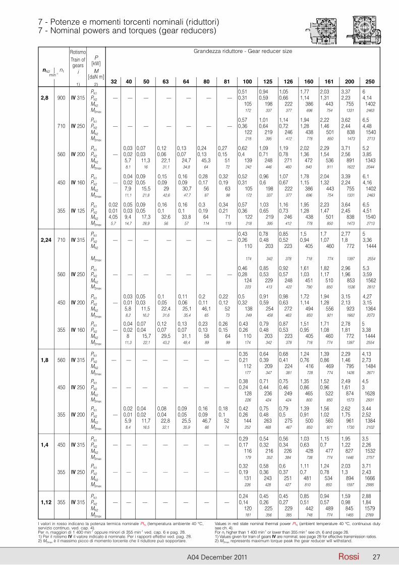
27A04 December 2011
I valori in rosso indicano la potenza termica nominale PtN (temperatura ambiente 40 °C, servizio continuo, ved. cap. 4).Per n1 maggiori di 1 400 min-1 oppure minori di 355 min-1 ved. cap. 6 e pag. 28.1) Per il rotismo IV il valore indicato è nominale. Per i rapporti effettivi ved. pag. 28.2) M2max è il massimo picco di momento torcente che il riduttore può sopportare.
Values in red state nominal thermal power PtN (ambient temperature 40 °C, continuous duty see ch. 4).For n1 higher than 1 400 min-1 or lower than 355 min-1 see ch. 6 and page 28.1) Values given for train of gears IV are nominal; see page 28 for effective transmission ratios.2) M2max represents maximum torque peak the gear reducer will withstand.
7 - Potenze e momenti torcenti nominali (riduttori)7 - Nominal powers and torques (gear reducers)
Grandezza riduttore - Gear reducer size
32 40 50 63 64 80 81 100 125 126 160 161 200 250
nN2 n1min-1
RotismoTrain ofgears
i
1)
P[kW]M
[daN m]2)
PN1 0,51 0,94 1,05 1,77 2,03 3,37 6 2,81 900 IV 315 PN2 — — — — — — — 0,31 0,59 0,66 1,14 1,31 2,23 4,14 MN2 105 198 222 386 443 755 1402 M2max 172 337 377 696 754 1331 2463
PN1 0,57 1,01 1,14 1,94 2,22 3,62 6,5 710 IV 250 PN2 — — — — — — — 0,36 0,64 0,72 1,28 1,46 2,44 4,48 MN2 122 219 246 438 501 838 1540 M2max 218 395 412 778 850 1473 2713
PN1 0,03 0,07 0,12 0,13 0,24 0,27 0,62 1,09 1,19 2,02 2,29 3,71 5,2 560 IV 200 PN2 — 0,02 0,03 0,06 0,07 0,13 0,15 0,4 0,71 0,78 1,36 1,54 2,56 3,85 MN2 5,7 11,3 22,1 24,7 45,3 51 139 248 271 472 536 891 1343 M2max 8,1 16 31,1 34,8 64 72 242 446 460 840 911 1622 2044
PN1 0,04 0,09 0,15 0,16 0,28 0,32 0,52 0,96 1,07 1,78 2,04 3,39 6,1 450 IV 160 PN2 — 0,02 0,05 0,09 0,09 0,17 0,19 0,31 0,6 0,67 1,15 1,32 2,24 4,16 MN2 7,9 15,5 29 30,7 56 63 105 198 222 386 443 755 1402 M2max 11,1 21,8 42,6 47,7 87 98 172 337 377 696 754 1331 2463
PN1 0,02 0,05 0,09 0,16 0,16 0,3 0,34 0,57 1,03 1,16 1,95 2,23 3,64 6,5 355 IV 125 PN2 0,01 0,03 0,05 0,1 0,1 0,19 0,21 0,36 0,65 0,73 1,28 1,47 2,45 4,51 MN2 4,05 9,4 17,3 32,6 33,8 64 71 122 219 246 438 501 838 1540 M2max 5,7 14,7 28,9 56 57 114 119 218 395 412 778 850 1473 2713
PN1 0,43 0,78 0,85 1,5 1,7 2,77 5 2,24 710 IV 315 PN2 — — — — — — — 0,26 0,48 0,52 0,94 1,07 1,8 3,36 MN2 110 203 223 405 460 772 1444
M2max 174 342 378 718 774 1397 2554
PN1 0,46 0,85 0,92 1,61 1,82 2,96 5,3 560 IV 250 PN2 — — — — — — — 0,28 0,53 0,57 1,03 1,17 1,96 3,59 MN2 124 229 248 451 510 853 1562 M2max 223 413 422 790 850 1536 2812
PN1 0,03 0,05 0,1 0,11 0,2 0,22 0,5 0,91 0,98 1,72 1,94 3,15 4,27 450 IV 200 PN2 — 0,01 0,03 0,05 0,06 0,11 0,12 0,32 0,59 0,63 1,14 1,28 2,13 3,15 MN2 5,8 11,5 22,4 25,1 46,1 52 138 254 272 494 556 923 1364 M2max 8,2 16,2 31,6 35,4 65 73 249 458 463 850 921 1662 2073
PN1 0,04 0,07 0,12 0,13 0,23 0,26 0,43 0,79 0,87 1,51 1,71 2,78 5 355 IV 160 PN2 — 0,02 0,04 0,07 0,07 0,13 0,15 0,26 0,48 0,53 0,95 1,08 1,81 3,38 MN2 8 15,7 29,5 31,1 58 64 110 203 223 405 460 772 1444 M2max 11,3 22,1 43,2 48,4 89 99 174 342 378 718 774 1397 2554
PN1 0,35 0,64 0,68 1,24 1,39 2,29 4,13 1,81 560 IV 315 PN2 — — — — — — — 0,21 0,39 0,41 0,76 0,86 1,46 2,73 MN2 112 209 224 416 469 795 1484 M2max 177 347 381 728 774 1426 2671
PN1 0,38 0,71 0,75 1,35 1,52 2,49 4,5 450 IV 250 PN2 — — — — — — — 0,24 0,44 0,46 0,86 0,96 1,61 3 MN2 128 236 249 465 522 874 1628 M2max 226 424 424 800 850 1573 2931
PN1 0,02 0,04 0,08 0,09 0,16 0,18 0,42 0,75 0,79 1,39 1,56 2,62 3,44 355 IV 200 PN2 — 0,01 0,02 0,04 0,05 0,09 0,1 0,26 0,48 0,5 0,91 1,02 1,75 2,52 MN2 5,9 11,7 22,8 25,5 46,7 52 144 263 275 500 560 961 1384 M2max 8,4 16,5 32,1 35,9 66 74 252 468 467 850 921 1730 2102
PN1 0,29 0,54 0,56 1,03 1,15 1,95 3,5 1,41 450 IV 315 PN2 — — — — — — — 0,17 0,32 0,34 0,63 0,7 1,22 2,26 MN2 116 216 226 428 477 827 1532 M2max 179 352 384 738 774 1446 2757
PN1 0,32 0,58 0,6 1,11 1,24 2,03 3,71 355 IV 250 PN2 — — — — — — — 0,19 0,36 0,37 0,7 0,78 1,3 2,43 MN2 131 243 251 481 534 894 1666 M2max 226 428 427 810 850 1597 2995
PN1 0,24 0,45 0,45 0,85 0,94 1,59 2,88 1,12 355 IV 315 PN2 — — — — — — — 0,14 0,26 0,27 0,51 0,57 0,98 1,84 MN2 120 225 229 442 489 845 1579 M2max 181 356 385 748 774 1465 2769
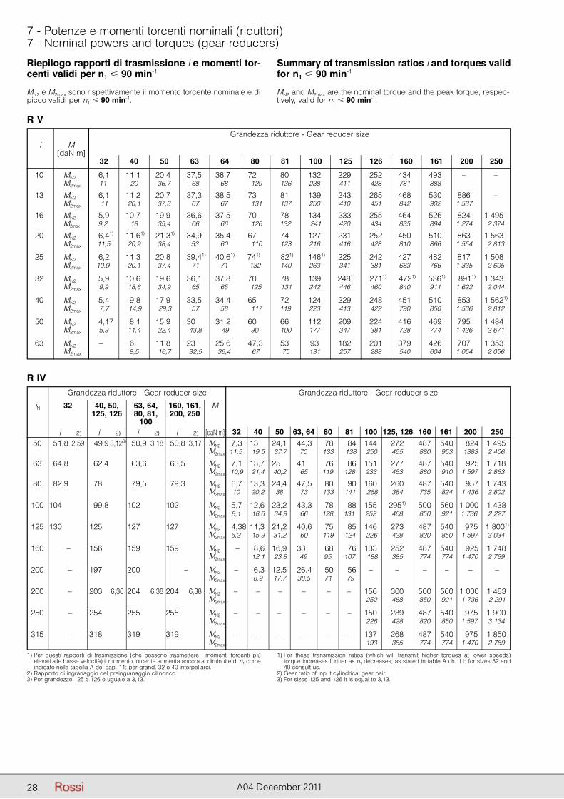
28 A04 December 2011
Riepilogo rapporti di trasmissione i e momenti tor-centi validi per n1 � 90 min-1
Summary of transmission ratios i and torques valid for n1 � 90 min-1
1) Per questi rapporti di trasmissione (che possono trasmettere i momenti torcenti più elevati alle basse velocità) il momento torcente aumenta ancora al diminuire di n1 come indicato nella tabella A del cap. 11; per grand. 32 e 40 interpellarci.
2) Rapporto di ingranaggio del preingranaggio cilindrico.3) Per grandezze 125 e 126 è uguale a 3,13.
1) For these transmission ratios (which will transmit higher torques at lower speeds) torque increases further as n1 decreases, as stated in table A ch. 11; for sizes 32 and 40 consult us.
2) Gear ratio of input cylindrical gear pair.3) For sizes 125 and 126 it is equal to 3,13.
7 - Potenze e momenti torcenti nominali (riduttori)7 - Nominal powers and torques (gear reducers)
Grandezza riduttore - Gear reducer size
32 40 50 63 64 80 81 100 125 126 160 161 200 250
i M[daN m]
MN2 e M2max sono rispettivamente il momento torcente nominale e di picco validi per n1 � 90 min-1.
MN2 and M2max are the nominal torque and the peak torque, respec-tively, valid for n1 � 90 min-1.
R V
Grandezza riduttore - Gear reducer sizeGrandezza riduttore - Gear reducer size
32 40 50 63, 64 80 81 100 125, 126 160 161 200 250
iN M
[daN m]
32 40, 50, 63, 64, 160, 161, 125, 126 80, 81, 200, 250 100 i 2) i 2) i 2) i 2)
50 51,8 2,59 49,9 3,123) 50,9 3,18 50,8 3,17 MN2 7,3 13 24,1 44,3 78 84 144 272 487 540 824 1 495 M2max 11,5 19,5 37,7 70 133 138 250 455 880 953 1383 2 406
63 64,8 62,4 63,6 63,5 MN2 7,1 13,7 25 41 76 86 151 277 487 540 925 1 718 M2max 10,9 21,4 40,2 65 119 128 233 453 880 910 1 597 2 863
80 82,9 78 79,5 79,3 MN2 6,7 13,3 24,4 47,5 80 90 160 260 487 540 957 1 743 M2max 10 20,2 38 73 133 141 268 384 735 824 1 436 2 802
100 104 99,8 102 102 MN2 5,7 12,6 23,2 43,3 78 88 155 2951) 500 560 1 000 1 438 M2max 8,1 18,6 34,9 66 128 131 252 468 850 921 1 736 2 227
125 130 125 127 127 MN2 4,38 11,3 21,2 40,6 75 85 146 273 487 540 975 1 8001)
M2max 6,2 15,9 31,2 60 119 124 226 428 820 850 1 597 3 034
160 – 156 159 159 MN2 – 8,6 16,9 33 68 76 133 252 487 540 925 1 748 M2max 12,1 23,8 49 95 107 188 385 774 774 1 470 2 769
200 – 197 200 – MN2 – 6,3 12,5 26,4 50 56 – – – – – – M2max 8,9 17,7 38,5 71 79
200 – 203 6,36 204 6,38 204 6,38 MN2 – – – – – – 156 300 500 560 1 000 1 483 M2max 252 468 850 921 1 736 2 291
250 – 254 255 255 MN2 – – – – – – 150 289 487 540 975 1 900 M2max 226 428 820 850 1 597 3 134
315 – 318 319 319 MN2 – – – – – – 137 268 487 540 975 1 850 M2max 193 385 774 774 1 470 2 769
R IV
10 MN2 6,1 11,1 20,4 37,5 38,7 72 80 132 229 252 434 493 – – M2max 11 20 36,7 68 68 129 136 238 411 428 781 888
13 MN2 6,1 11,2 20,7 37,3 38,5 73 81 139 243 265 468 530 886 – M2max 11 20,1 37,3 67 67 131 137 250 410 451 842 902 1 537
16 MN2 5,9 10,7 19,9 36,6 37,5 70 78 134 233 255 464 526 824 1 4951)
M2max 9,2 18 35,4 66 66 126 132 241 420 434 835 894 1 274 2 374
20 MN2 6,41) 11,61) 21,31) 34,9 35,4 67 74 127 231 252 450 510 863 1 5631)
M2max 11,5 20,9 38,4 53 60 110 123 216 416 428 810 866 1 554 2 813
25 MN2 6,2 11,3 20,8 39,41) 40,61) 741) 821) 1461) 225 242 427 482 817 1 5081)
M2max 10,9 20,1 37,4 71 71 132 140 263 341 381 683 766 1 335 2 605
32 MN2 5,9 10,6 19,6 36,1 37,8 70 78 139 2481) 2711) 4721) 5361) 8911) 1 3431)
M2max 9,9 18,6 34,9 65 65 125 131 242 446 460 840 911 1 622 2 044
40 MN2 5,4 9,8 17,9 33,5 34,4 65 72 124 229 248 451 510 853 1 5621)
M2max 7,7 14,9 29,3 57 58 117 119 223 413 422 790 850 1 536 2 812
50 MN2 4,17 8,1 15,9 30 31,2 60 66 112 209 224 416 469 795 1 4841)
M2max 5,9 11,4 22,4 43,8 49 90 100 177 347 381 728 774 1 426 2 671
63 MN2 – 6 11,8 23 25,6 47,3 53 93 182 201 379 426 707 1 3531)
M2max 8,5 16,7 32,5 36,4 67 75 131 257 288 540 604 1 054 2 056

29A04 December 2011
Pagina lasciata intenzionalmente bianca.This page is intentionally left blank.
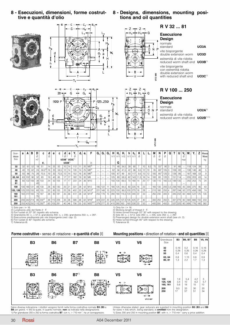
30 A04 December 2011
8 - Esecuzioni, dimensioni, forme costrut-tive e quantità d’olio
8 - Designs, dimensions, mounting posi-tions and oil quantities
R V 32 ... 81
R V 100 ... 250
Salvo diversa indicazione i riduttori vengono forniti nella forma costruttiva normale B3 (B3 e B8 per grand. � 64) la quale, in quanto normale, non va indicata nella designazione.1) Per grandezze 200 e 250 la forma costruttiva B7, con n1 � 710 min-1, ha un sovrapprezzo.
Unless otherwise stated, gear reducers are supplied in mounting position B3 (B3 and B8 for sizes � 64) which, being standard, is omitted from the designation.1) Sizes 200 and 250 in mounting position B7, with n1 � 710 min-1 carry a price addition.
EsecuzioneDesign normalestandard UO3A1) 5)
vite bisporgentedouble extension worm UO3D1) 5)
estremità di vite ridottareduced worm shaft end UO3B1) 5)
vite bisporgentecon estremità ridottadouble extension wormwith reduced shaft end UO3C1) 5)
EsecuzioneDesign normalestandard UO2A5) 5)
estremità di vite ridottareduced worm shaft end UO2B1) 5)
1) Solo per i � 16.2) Lunghezza utile del filetto 2 · F.3) Fori ruotati di 22° 30’ rispetto allo schema.4) Grandezza 40: c1 = 57,5; grandezza 200: c1 = 235; grandezza 250: c1 = 287.5) Esecuzione predisposta per vite bisporgente (ved. cap. 2).6) Fori ruotati di 45° rispetto allo schema.7) Tolleranza t8.
1) Only for i � 16.2) Working length of thread 2 · F.3) Holes turned through 22° 30’ with respect to the drawing.4) Size 40: c1 = 57,5; size 200: c1 = 235; size 250: c1 = 287.5) Prearranged design for double extension worm shaft (see ch. 2).6) Holes turned through 45° with respect to the drawing.7) Tolerance t8.
Gran- a A B D c d e c d e Y1 d1 e1 F G0 G1 G2 H H0 H1 h h0 K L L1 M N P Q T U V0 W1 Y1 Z Massa dezza Ø Ø Ø Ø h11 h11 h12 h11 h11 Ø Ø Ø Ø Ø Mass Size H7 UO3B1) UO3C1) h6 max kg c1 UO2B1) 2) G 32 32 61 52 19 51,54) 14 25 50,5 10 14 112 11 20 M56) – – – 71 48 34,5 39 80 7,5 10 8,5 75 557) 90 3,5 91 66 – 119 124 39 3 40 40 70 62 24 59,54) 16 30 59,5 12 14 130 14 25 M66) – – – 82 56 41,5 42 96 9,5 12 10,5 85 687) 105 3,5 106 80 – 138 146 46 5 50 50 86 75 28 70,5, 19 30 70,5 12 14 152 16 30 M66) – – – 100 67 49 50 117 9,5 13 12,5 100 857) 120 3,5 126 95 – 167 168 53 9 63, 64 63 102 90 32 83,54) 19 40 85,5 17 17 182 19 30 M8 – – – 125 80 58,5 62 143 11,5 16 14,5 100 807) 120 3,5 151 114 – 205 203 63 14 80 80 132 106 38 103,54) 24 50 105,5 17 17 222 24 36 M10 – – – 150 100 69,5 70 180 14,5 20 17,5 130 1107) 160 3,5 189 135 – 250 253 75 24 81 40 ,54) ,5 ,5 ,5 – 100 100 180 131 48 130,54) 28 60 130,5 20 21 331 28 42 M12 180 122 11 180 125 84,5 80 225 16,5 23 – 165 1307) 200 3,5 236 165 45 305 370 90 43 125, 126 125 225 155 60 155,54) 32 80 155,5 25 26 402 32 58 M128 221 148 15 225 150 99,5 100 275 18,5 28 – 215 1807) 250 4,5 287 194 50 375 456 106 174 160 160 272 183 70 187,54) 38 80 181,5 35 36 472 38 58 M148 255 178 15 280 180 118,5 120 340 22,5 33 – 265 2307) 300 4,5 345 232 60 460 522 125 130 161 75 ,54) ,5 ,5 ,5 200 200 342 214 90 2324),5 48 110 226,5 35 36 586 48 82 M168 324 222 20 335 225 137,5 135 425 27,5 40 – 300 2507) 350 5,5 431 270 80 560 666 150 233 250 250 425 250 110 2924),0 ) 60 105 281,5 40 46 706 55 82 M208 3) 379 277 20 410 280 163 160 530 33,5 50 – 400 3507)) 450 5,5 537 320 80 690 776 180 382
UT.C
685
UT.
C 6
86
Forme costruttive - senso di rotazione - e quantità d’olio [l] Mounting positions - direction of rotation - and oil quantities [l] Grandezza B3 B6, B7 B8 V5, V6 Size
32, 81 0,16 0,22 0,16 0,16 40, 81 0,26 0,35 0,26 0,26 50, 81 0,46 0,62 0,42 0,42
63, 64 0,86 1,15 0,82 0,82 80, 81 1,36 2,22 1,72 1,32
100, 8 1 1,9 5,4 4,2 3,7 125, 126 3,4 10,4 8,2 5,7 160, 161 5,6 18,4 15,2 10,7
200, 126 9,56 33,2 30,2 202 250, 126 17,56 57,2 51,2 342
B3 B6 B7 B8 V5 V6
B3 B6 B71) B8 V5 V6
UT.C 687
30
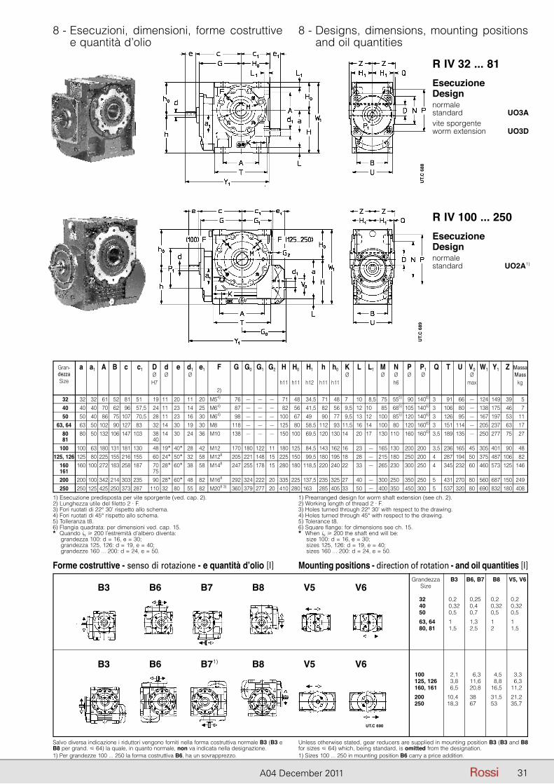
31A04 December 2011
8 - Esecuzioni, dimensioni, forme costruttive e quantità d’olio
8 - Designs, dimensions, mounting positions and oil quantities
Gran- a a1 A B c c1 D d e d1 e1 F G G0 G1 G2 H H0 H1 h h0 K L L1 M N P P1 Q T U V0 W1 Y1 Z Massa dezza Ø Ø Ø Ø Ø Ø Ø Ø Ø Mass Size H7 h11 h11 h12 h11 h11 h6 max kg 2)
32 32 32 61 52 81 51,0 19 11* 20* 11 20 M54) 76 – – – 71 48 34,5 71 48 7,0 10 8,5 75 555) 90 1406) 3,0 91 66 – 124 149 39 5 40 40 40 70 62 96 57,5 24 11* 23* 14 25 M64) 87 – – – 82 56 41,5 82 56 9,5 12 10,5 85 685) 105 1406) 3,0 106 80 – 138 175 46 7 50 50 40 86 75 107 70,5 28 11* 23* 16 30 M64) 98 – – – 100 67 49,5 90 77 9,5 13 12,5 100 855) 120 1406) 3,0 126 95 – 167 197 53 11 63, 64 63 50 102 90 127 83,0 32 14* 30* 19 30 M8 118 – – – 125 80 58,5 112 93 11,5 16 14,5 100 805) 120 1606) 3,0 151 114 – 205 237 63 17 80 80 50 132 106 147 103,0 38 14* 30* 24 36 M10 138 – – – 150 100 69,5 120 130 14,0 20 17,5 130 1105) 160 1606) 3,5 189 135 – 250 277 75 27 81 40 100 100 63 180 131 181 130,0 48 19* 40* 28 42 M12 170 180 122 11 180 125 84,5 143 162 16,0 23 – 165 1305) 200 2006) 3,5 236 165 45 305 401 90 48 125, 126 125 80 225 155 216 155,0 60 24* 50* 32 58 M128 205 221 148 15 225 150 99,5 180 195 18,0 28 – 215 1805) 250 2006) 4,0 287 194 50 375 487 106 82 160 160 100 272 183 258 187,0 70 28* 60* 38 58 M148 247 255 178 15 280 180 118,5 220 240 22,0 33 – 265 2305) 300 2506) 4,0 345 232 60 460 573 125 146 161 75 200 200 100 342 214 303 235,0 90 28* 60* 48 82 M168 292 324 222 20 335 225 137,5 235 325 27,0 40 – 300 2505) 350 2506) 5,0 431 270 80 560 687 150 249 250 250 125 425 250 373 287,0 110 32* 80* 55 82 M208 3) 360 379 277 20 410 280 163,5 285 405 33,0 50 – 400 3505) 450 3006) 5,0 537 320 80 690 832 180 408
1) Esecuzione predisposta per vite sporgente (ved. cap. 2).2) Lunghezza utile del filetto 2 · F.3) Fori ruotati di 22° 30’ rispetto allo schema.4) Fori ruotati di 45° rispetto allo schema.5) Tolleranza t8.6) Flangia quadrata: per dimensioni ved. cap. 15.* Quando iN � 200 l’estremità d’albero diventa: grandezza 100: d = 16, e = 30; grandezza 125, 126: d = 19, e = 40; grandezze 160 ... 200: d = 24, e = 50.
1) Prearranged design for worm shaft extension (see ch. 2).2) Working length of thread 2 · F.3) Holes turned through 22° 30’ with respect to the drawing.4) Holes turned through 45° with respect to the drawing.5) Tolerance t8.6) Square flange: for dimensions see ch. 15.* When iN � 200 the shaft end will be: size 100: d = 16, e = 30; sizes 125, 126: d = 19, e = 40; sizes 160 ... 200: d = 24, e = 50.
Salvo diversa indicazione i riduttori vengono forniti nella forma costruttiva normale B3 (B3 e B8 per grand. � 64) la quale, in quanto normale, non va indicata nella designazione.1) Per grandezze 100 ... 250 la forma costruttiva B6, ha un sovrapprezzo.
Unless otherwise stated, gear reducers are supplied in mounting position B3 (B3 and B8 for sizes � 64) which, being standard, is omitted from the designation.1) Sizes 100 ... 250 in mounting position B6 carry a price addition.
R IV 32 ... 81
R IV 100 ... 250
EsecuzioneDesign normalestandard UO3A1)
vite sporgenteworm extension UO3D1)
EsecuzioneDesign normalestandard UO2A1) )
UT.
C 6
88U
T.C
689
Forme costruttive - senso di rotazione - e quantità d’olio [l] Mounting positions - direction of rotation - and oil quantities [l] Grandezza B3 B6, B7 B8 V5, V6 Size
32, 81 0,26 0,25 0,20 0,26 40, 81 0,32 0,45 0,32 0,32 50, 81 0,56 0,72 0,50 0,52
63, 64 1,86 1,35 1,82 1,82 80, 81 1,56 2,52 2,72 1,52
100, 8 1 2,1 6,3 4,5 3,3 125, 126 3,8 11,6 8,8 6,3 160, 161 6,5 20,8 16,5 11,2
200, 126 10,46 38,2 31,5 21,2 250, 126 18,36 67,2 53,2 35,7
B3 B6 B7 B8 V5 V6
B3 B6 B71) B8 V5 V6
UT.C 690
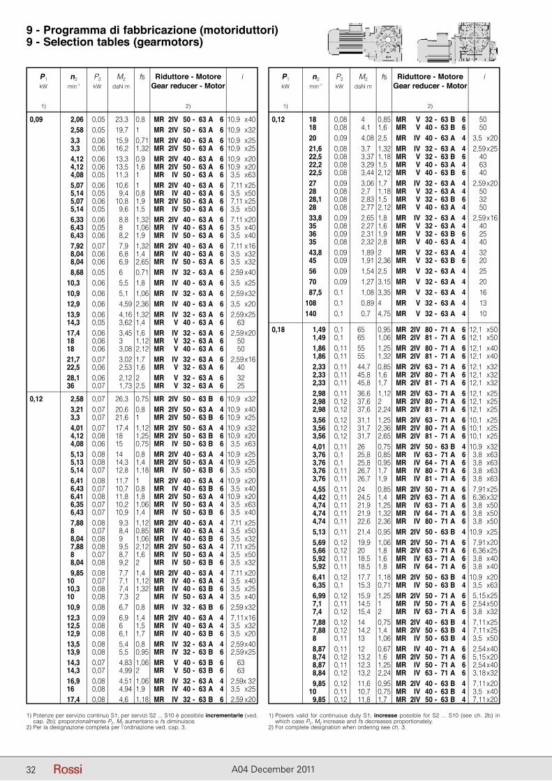
P1 n2 P2 M2 fs Riduttore - Motore i kW min-1 kW daN m Gear reducer - Motor
1) 2)
P1 n2 P2 M2 fs Riduttore - Motore i kW min-1 kW daN m Gear reducer - Motor
1) 2)
32 A04 December 2011
9 - Programma di fabbricazione (motoriduttori)9 - Selection tables (gearmotors)
P1 n2 P2 M2 fs Riduttore - Motore i kW min-1 kW daN m Gear reducer - Motor
1) 2)
1) Potenze per servizio continuo S1; per servizi S2 ... S10 è possibile incrementarle (ved. cap. 2b); proporzionalmente P2, M2 aumentano e fs diminuisce.
2) Per la designazione completa per l’ordinazione ved. cap. 3.
1) Powers valid for continuous duty S1; increase possible for S2 ... S10 (see ch. 2b) in which case P2, M2 increase and fs decreases proportionately.
2) For complete designation when ordering see ch. 3.
0,09 2,06 0,05 23,3 0,8 MR 2IV 50 - 63 A 6 10,9 x 40 2,58 0,05 19,7 1 MR 2IV 50 - 63 A 6 10,9 x 32 3,3 0,06 15,9 0,71 MR 2IV 40 - 63 A 6 10,9 x 25 3,3 0,06 16,2 1,32 MR 2IV 50 - 63 A 6 10,9 x 25 4,12 0,06 13,3 0,9 MR 2IV 40 - 63 A 6 10,9 x 20 4,12 0,06 13,5 1,6 MR 2IV 50 - 63 A 6 10,9 x 20 4,08 0,05 11,3 1 MR IV 50 - 63 A 6 23,5 x 63 5,07 0,06 10,6 1 MR 2IV 40 - 63 A 6 27,11 x 25 5,14 0,05 9,4 0,8 MR IV 40 - 63 A 6 23,5 x 50 5,07 0,06 10,8 1,9 MR 2IV 50 - 63 A 6 27,11 x 25 5,14 0,05 9,6 1,5 MR IV 50 - 63 A 6 23,5 x 50 6,33 0,06 8,8 1,32 MR 2IV 40 - 63 A 6 27,11 x 20 6,43 0,05 8 1,06 MR IV 40 - 63 A 6 23,5 x 40 6,43 0,06 8,2 1,9 MR IV 50 - 63 A 6 23,5 x 40 7,92 0,07 7,9 1,32 MR 2IV 40 - 63 A 6 27,11 x 16 8,04 0,06 6,8 1,4 MR IV 40 - 63 A 6 23,5 x 32 8,04 0,06 6,9 2,65 MR IV 50 - 63 A 6 23,5 x 32 8,68 0,05 6 0,71 MR IV 32 - 63 A 6 22,59 x 40 10,3 0,06 5,5 1,8 MR IV 40 - 63 A 6 23,5 x 25 10,9 0,06 5,1 1,06 MR IV 32 - 63 A 6 22,59 x 32 12,9 0,06 4,59 2,36 MR IV 40 - 63 A 6 23,5 x 20 13,9 0,06 4,16 1,32 MR IV 32 - 63 A 6 22,59 x 25 14,3 0,05 3,62 1,4 MR V 40 - 63 A 6 63 17,4 0,06 3,45 1,6 MR IV 32 - 63 A 6 22,59 x 20 18 0,06 3 1,12 MR V 32 - 63 A 6 50 18 0,06 3,08 2,12 MR V 40 - 63 A 6 50 21,7 0,07 3,02 1,7 MR IV 32 - 63 A 6 22,59 x 16 22,5 0,06 2,53 1,6 MR V 32 - 63 A 6 40 28,1 0,06 2,12 2 MR V 32 - 63 A 6 32 36 0,07 1,73 2,5 MR V 32 - 63 A 6 25
0,12 2,58 0,07 26,3 0,75 MR 2IV 50 - 63 B 6 10,9 x 32 3,21 0,07 20,6 0,8 MR 2IV 50 - 63 A 4 10,9 x 40 3,3 0,07 21,6 1 MR 2IV 50 - 63 B 6 10,9 x 25 4,01 0,07 17,4 1,12 MR 2IV 50 - 63 A 4 10,9 x 32 4,12 0,08 18 1,25 MR 2IV 50 - 63 B 6 10,9 x 20 4,08 0,06 15 0,75 MR IV 50 - 63 B 6 23,5 x 63 5,13 0,08 14 0,8 MR 2IV 40 - 63 A 4 10,9 x 25 5,13 0,08 14,3 1,4 MR 2IV 50 - 63 A 4 10,9 x 25 5,14 0,07 12,8 1,18 MR IV 50 - 63 B 6 23,5 x 50 6,41 0,08 11,7 1 MR 2IV 40 - 63 A 4 10,9 x 20 6,43 0,07 10,7 0,8 MR IV 40 - 63 B 6 23,5 x 40 6,41 0,08 11,8 1,8 MR 2IV 50 - 63 A 4 10,9 x 20 6,35 0,07 10,2 1,06 MR IV 50 - 63 A 4 23,5 x 63 6,43 0,07 10,9 1,4 MR IV 50 - 63 B 6 23,5 x 40 7,88 0,08 9,3 1,12 MR 2IV 40 - 63 A 4 27,11 x 25 8 0,07 8,4 0,85 MR IV 40 - 63 A 4 23,5 x 50 8,04 0,08 9 1,06 MR IV 40 - 63 B 6 23,5 x 32 7,88 0,08 9,5 2,12 MR 2IV 50 - 63 A 4 27,11 x 25 8 0,07 8,7 1,6 MR IV 50 - 63 A 4 23,5 x 50 8,04 0,08 9,2 2 MR IV 50 - 63 B 6 23,5 x 32 9,85 0,08 7,7 1,4 MR 2IV 40 - 63 A 4 27,11 x 20 10 0,07 7,1 1,12 MR IV 40 - 63 A 4 23,5 x 40 10,3 0,08 7,4 1,32 MR IV 40 - 63 B 6 23,5 x 25 10 0,08 7,3 2 MR IV 50 - 63 A 4 23,5 x 40 10,9 0,08 6,7 0,8 MR IV 32 - 63 B 6 22,59 x 32 12,3 0,09 6,9 1,4 MR 2IV 40 - 63 A 4 27,11 x 16 12,5 0,08 6 1,5 MR IV 40 - 63 A 4 23,5 x 32 12,9 0,08 6,1 1,7 MR IV 40 - 63 B 6 23,5 x 20 13,5 0,08 5,4 0,8 MR IV 32 - 63 A 4 22,59 x 40 13,9 0,08 5,5 0,95 MR IV 32 - 63 B 6 22,59 x 25 14,3 0,07 4,83 1,06 MR V 40 - 63 B 6 63 14,3 0,07 4,99 2 MR V 50 - 63 B 6 63 16,9 0,08 4,51 1,06 MR IV 32 - 63 A 4 22,59x 32 16 0,08 4,94 1,9 MR IV 40 - 63 A 4 23,5 x 25 17,4 0,08 4,6 1,18 MR IV 32 - 63 B 6 22,59 x 20
P1 n2 P2 M2 fs Riduttore - Motore i kW min-1 kW daN m Gear reducer - Motor
1) 2)
0,12 18 0,08 4 0,85 MR V 32 - 63 B 6 50 18 0,08 4,1 1,6 MR V 40 - 63 B 6 50 20 0,09 4,08 2,5 MR IV 40 - 63 A 4 13,5 x 20 21,6 0,08 3,7 1,32 MR IV 32 - 63 A 4 12,59 x 25 22,5 0,08 3,37 1,18 MR V 32 - 63 B 6 40 22,2 0,08 3,29 1,5 MR V 40 - 63 A 4 63 22,5 0,08 3,44 2,12 MR V 40 - 63 B 6 40 27 0,09 3,06 1,7 MR IV 32 - 63 A 4 12,59 x 20 28 0,08 2,7 1,18 MR V 32 - 63 A 4 50 28,1 0,08 2,83 1,5 MR V 32 - 63 B 6 32 28 0,08 2,77 2,12 MR V 40 - 63 A 4 50 33,8 0,09 2,65 1,8 MR IV 32 - 63 A 4 12,59 x 16 35 0,08 2,27 1,6 MR V 32 - 63 A 4 40 36 0,09 2,31 1,9 MR V 32 - 63 B 6 25 35 0,08 2,32 2,8 MR V 40 - 63 A 4 40 43,8 0,09 1,89 2 MR V 32 - 63 A 4 32 45 0,09 1,91 2,36 MR V 32 - 63 B 6 20 56 0,09 1,54 2,5 MR V 32 - 63 A 4 25 70 0,09 1,27 3,15 MR V 32 - 63 A 4 20 87,5 0,1 1,08 3,35 MR V 32 - 63 A 4 16 108 0,1 0,89 4 MR V 32 - 63 A 4 13 140 0,1 0,7 4,75 MR V 32 - 63 A 4 10
0,18 1,49 0,1 65 0,95 MR 2IV 80 - 71 A 6 12,1 x 50 1,49 0,1 65 1,06 MR 2IV 81 - 71 A 6 12,1 x 50 1,86 0,11 55 1,25 MR 2IV 80 - 71 A 6 12,1 x 40 1,86 0,11 55 1,32 MR 2IV 81 - 71 A 6 12,1 x 40 2,33 0,11 44,7 0,85 MR 2IV 63 - 71 A 6 12,1 x 32 2,33 0,11 45,8 1,6 MR 2IV 80 - 71 A 6 12,1 x 32 2,33 0,11 45,8 1,7 MR 2IV 81 - 71 A 6 12,1 x 32 2,98 0,11 36,6 1,12 MR 2IV 63 - 71 A 6 12,1 x 25 2,98 0,12 37,6 2 MR 2IV 80 - 71 A 6 12,1 x 25 2,98 0,12 37,6 2,24 MR 2IV 81 - 71 A 6 12,1 x 25 3,56 0,12 31,1 1,25 MR 2IV 63 - 71 A 6 10,1 x 25 3,56 0,12 31,7 2,36 MR 2IV 80 - 71 A 6 10,1 x 25 3,56 0,12 31,7 2,65 MR 2IV 81 - 71 A 6 10,1 x 25 4,01 0,11 26 0,75 MR 2IV 50 - 63 B 4 10,9 x 32 3,76 0,1 25,8 0,85 MR IV 63 - 71 A 6 13,8 x 63 3,76 0,1 25,8 0,95 MR IV 64 - 71 A 6 13,8 x 63 3,76 0,11 26,7 1,7 MR IV 80 - 71 A 6 13,8 x 63 3,76 0,11 26,7 1,9 MR IV 81 - 71 A 6 13,8 x 63 4,55 0,11 24 0,85 MR 2IV 50 - 71 A 6 17,91 x 25 4,42 0,11 24,5 1,4 MR 2IV 63 - 71 A 6 16,36 x 32 4,74 0,11 21,9 1,25 MR IV 63 - 71 A 6 13,8 x 50 4,74 0,11 21,9 1,32 MR IV 64 - 71 A 6 13,8 x 50 4,74 0,11 22,6 2,36 MR IV 80 - 71 A 6 13,8 x 50 5,13 0,11 21,4 0,95 MR 2IV 50 - 63 B 4 10,9 x 25 5,69 0,12 19,9 1,06 MR 2IV 50 - 71 A 6 17,91 x 20 5,66 0,12 20 1,8 MR 2IV 63 - 71 A 6 16,36 x 25 5,92 0,11 18,5 1,6 MR IV 63 - 71 A 6 13,8 x 40 5,92 0,11 18,5 1,8 MR IV 64 - 71 A 6 13,8 x 40 6,41 0,12 17,7 1,18 MR 2IV 50 - 63 B 4 10,9 x 20 6,35 0,1 15,3 0,71 MR IV 50 - 63 B 4 13,5 x 63 6,99 0,12 15,9 1,25 MR 2IV 50 - 71 A 6 15,15 x 25 7,1 0,11 14,5 1 MR IV 50 - 71 A 6 12,54 x 50 7,4 0,12 15,4 2 MR IV 63 - 71 A 6 13,8 x 32 7,88 0,12 14 0,75 MR 2IV 40 - 63 B 4 17,11 x 25 7,88 0,12 14,2 1,4 MR 2IV 50 - 63 B 4 17,11 x 25 8 0,11 13 1,06 MR IV 50 - 63 B 4 13,5 x 50 8,87 0,11 12 0,67 MR IV 40 - 71 A 6 12,54 x 40 8,74 0,12 13,2 1,6 MR 2IV 50 - 71 A 6 15,15 x 20 8,87 0,11 12,3 1,25 MR IV 50 - 71 A 6 12,54 x 40 8,84 0,12 13,2 2,24 MR IV 63 - 71 A 6 13,18 x 32 9,85 0,12 11,6 0,95 MR 2IV 40 - 63 B 4 17,11 x 20 10 0,11 10,7 0,75 MR IV 40 - 63 B 4 13,5 x 40 9,85 0,12 11,8 1,7 MR 2IV 50 - 63 B 4 17,11 x 20
32
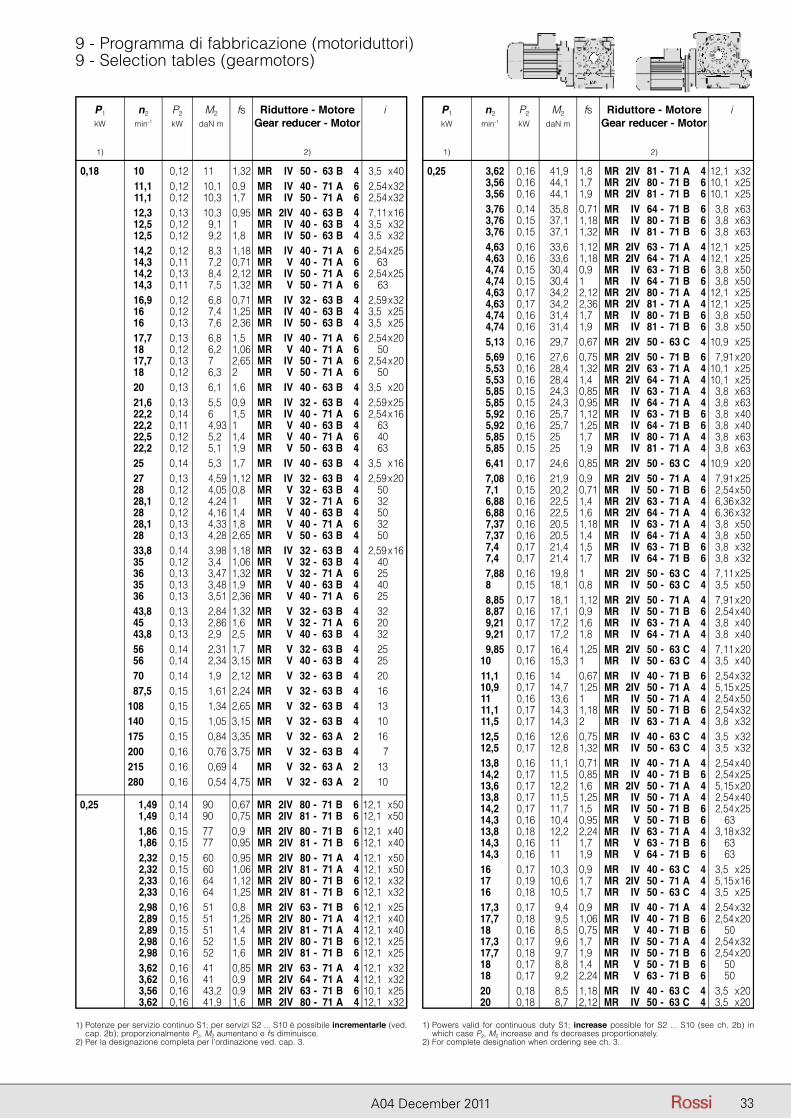
P1 n2 P2 M2 fs Riduttore - Motore i kW min-1 kW daN m Gear reducer - Motor
1) 2)
P1 n2 P2 M2 fs Riduttore - Motore i kW min-1 kW daN m Gear reducer - Motor
1) 2)
33A04 December 2011
9 - Programma di fabbricazione (motoriduttori)9 - Selection tables (gearmotors)
P1 n2 P2 M2 fs Riduttore - Motore i kW min-1 kW daN m Gear reducer - Motor
1) 2)
1) Potenze per servizio continuo S1; per servizi S2 ... S10 è possibile incrementarle (ved. cap. 2b); proporzionalmente P2, M2 aumentano e fs diminuisce.
2) Per la designazione completa per l’ordinazione ved. cap. 3.
1) Powers valid for continuous duty S1; increase possible for S2 ... S10 (see ch. 2b) in which case P2, M2 increase and fs decreases proportionately.
2) For complete designation when ordering see ch. 3.
0,18 10 0,12 11 1,32 MR IV 50 - 63 B 4 13,5 x 40 11,1 0,12 10,1 0,9 MR IV 40 - 71 A 6 12,54 x 32 11,1 0,12 10,3 1,7 MR IV 50 - 71 A 6 12,54 x 32 12,3 0,13 10,3 0,95 MR 2IV 40 - 63 B 4 17,11 x 16 12,5 0,12 9,1 1 MR IV 40 - 63 B 4 13,5 x 32 12,5 0,12 9,2 1,8 MR IV 50 - 63 B 4 13,5 x 32 14,2 0,12 8,3 1,18 MR IV 40 - 71 A 6 12,54 x 25 14,3 0,11 7,2 0,71 MR V 40 - 71 A 6 1 63 14,2 0,13 8,4 2,12 MR IV 50 - 71 A 6 12,54 x 25 14,3 0,11 7,5 1,32 MR V 50 - 71 A 6 63 16,9 0,12 6,8 0,71 MR IV 32 - 63 B 4 12,59 x 32 16 0,12 7,4 1,25 MR IV 40 - 63 B 4 13,5 x 25 16 0,13 7,6 2,36 MR IV 50 - 63 B 4 13,5 x 25 17,7 0,13 6,8 1,5 MR IV 40 - 71 A 6 12,54 x 20 18 0,12 6,2 1,06 MR V 40 - 71 A 6 50 17,7 0,13 7 2,65 MR IV 50 - 71 A 6 12,54 x 20 18 0,12 6,3 2 MR V 50 - 71 A 6 50 20 0,13 6,1 1,6 MR IV 40 - 63 B 4 13,5 x 20 21,6 0,13 5,5 0,9 MR IV 32 - 63 B 4 12,59 x 25 22,2 0,14 6 1,5 MR IV 40 - 71 A 6 12,54 x 16 22,2 0,11 4,93 1 MR V 40 - 63 B 4 63 22,5 0,12 5,2 1,4 MR V 40 - 71 A 6 40 22,2 0,12 5,1 1,9 MR V 50 - 63 B 4 63 25 0,14 5,3 1,7 MR IV 40 - 63 B 4 13,5 x 16 27 0,13 4,59 1,12 MR IV 32 - 63 B 4 12,59 x 20 28 0,12 4,05 0,8 MR V 32 - 63 B 4 50 28,1 0,12 4,24 1 MR V 32 - 71 A 6 32 28 0,12 4,16 1,4 MR V 40 - 63 B 4 50 28,1 0,13 4,33 1,8 MR V 40 - 71 A 6 32 28 0,13 4,28 2,65 MR V 50 - 63 B 4 50 33,8 0,14 3,98 1,18 MR IV 32 - 63 B 4 12,59 x 16 35 0,12 3,4 1,06 MR V 32 - 63 B 4 40 36 0,13 3,47 1,32 MR V 32 - 71 A 6 25 35 0,13 3,48 1,9 MR V 40 - 63 B 4 40 36 0,13 3,51 2,36 MR V 40 - 71 A 6 25 43,8 0,13 2,84 1,32 MR V 32 - 63 B 4 32 45 0,13 2,86 1,6 MR V 32 - 71 A 6 20 43,8 0,13 2,9 2,5 MR V 40 - 63 B 4 32 56 0,14 2,31 1,7 MR V 32 - 63 B 4 25 56 0,14 2,34 3,15 MR V 40 - 63 B 4 25 70 0,14 1,9 2,12 MR V 32 - 63 B 4 20 87,5 0,15 1,61 2,24 MR V 32 - 63 B 4 16 108 0,15 1,34 2,65 MR V 32 - 63 B 4 13 140 0,15 1,05 3,15 MR V 32 - 63 B 4 10 175 0,15 0,84 3,35 MR V 32 - 63 A 2 16 200 0,16 0,76 3,75 MR V 32 - 63 B 4 7 215 0,16 0,69 4 MR V 32 - 63 A 2 13 280 0,16 0,54 4,75 MR V 32 - 63 A 2 10
0,25 1,49 0,14 90 0,67 MR 2IV 80 - 71 B 6 12,1 x 50 1,49 0,14 90 0,75 MR 2IV 81 - 71 B 6 12,1 x 50 1,86 0,15 77 0,9 MR 2IV 80 - 71 B 6 12,1 x 40 1,86 0,15 77 0,95 MR 2IV 81 - 71 B 6 12,1 x 40 2,32 0,15 60 0,95 MR 2IV 80 - 71 A 4 12,1 x 50 2,32 0,15 60 1,06 MR 2IV 81 - 71 A 4 12,1 x 50 2,33 0,16 64 1,12 MR 2IV 80 - 71 B 6 12,1 x 32 2,33 0,16 64 1,25 MR 2IV 81 - 71 B 6 12,1 x 32 2,98 0,16 51 0,8 MR 2IV 63 - 71 B 6 12,1 x 25 2,89 0,15 51 1,25 MR 2IV 80 - 71 A 4 12,1 x 40 2,89 0,15 51 1,4 MR 2IV 81 - 71 A 4 12,1 x 40 2,98 0,16 52 1,5 MR 2IV 80 - 71 B 6 12,1 x 25 2,98 0,16 52 1,6 MR 2IV 81 - 71 B 6 12,1 x 25 3,62 0,16 41 0,85 MR 2IV 63 - 71 A 4 12,1 x 32 3,62 0,16 41 0,9 MR 2IV 64 - 71 A 4 12,1 x 32 3,56 0,16 43,2 0,9 MR 2IV 63 - 71 B 6 10,1 x 25 3,62 0,16 41,9 1,6 MR 2IV 80 - 71 A 4 12,1 x 32
P1 n2 P2 M2 fs Riduttore - Motore i kW min-1 kW daN m Gear reducer - Motor
1) 2)
0,25 3,62 0,16 41,9 1,8 MR 2IV 81 - 71 A 4 12,1 x 32 3,56 0,16 44,1 1,7 MR 2IV 80 - 71 B 6 10,1 x 25 3,56 0,16 44,1 1,9 MR 2IV 81 - 71 B 6 10,1 x 25 3,76 0,14 35,8 0,71 MR IV 64 - 71 B 6 13,8 x 63 3,76 0,15 37,1 1,18 MR IV 80 - 71 B 6 13,8 x 63 3,76 0,15 37,1 1,32 MR IV 81 - 71 B 6 13,8 x 63 4,63 0,16 33,6 1,12 MR 2IV 63 - 71 A 4 12,1 x 25 4,63 0,16 33,6 1,18 MR 2IV 64 - 71 A 4 12,1 x 25 4,74 0,15 30,4 0,9 MR IV 63 - 71 B 6 13,8 x 50 4,74 0,15 30,4 1 MR IV 64 - 71 B 6 13,8 x 50 4,63 0,17 34,2 2,12 MR 2IV 80 - 71 A 4 12,1 x 25 4,63 0,17 34,2 2,36 MR 2IV 81 - 71 A 4 12,1 x 25 4,74 0,16 31,4 1,7 MR IV 80 - 71 B 6 13,8 x 50 4,74 0,16 31,4 1,9 MR IV 81 - 71 B 6 13,8 x 50 5,13 0,16 29,7 0,67 MR 2IV 50 - 63 C 4 10,9 x 25 5,69 0,16 27,6 0,75 MR 2IV 50 - 71 B 6 17,91 x 20 5,53 0,16 28,4 1,32 MR 2IV 63 - 71 A 4 10,1 x 25 5,53 0,16 28,4 1,4 MR 2IV 64 - 71 A 4 10,1 x 25 5,85 0,15 24,3 0,85 MR IV 63 - 71 A 4 13,8 x 63 5,85 0,15 24,3 0,95 MR IV 64 - 71 A 4 13,8 x 63 5,92 0,16 25,7 1,12 MR IV 63 - 71 B 6 13,8 x 40 5,92 0,16 25,7 1,25 MR IV 64 - 71 B 6 13,8 x 40 5,85 0,15 25 1,7 MR IV 80 - 71 A 4 13,8 x 63 5,85 0,15 25 1,9 MR IV 81 - 71 A 4 13,8 x 63 6,41 0,17 24,6 0,85 MR 2IV 50 - 63 C 4 10,9 x 20 7,08 0,16 21,9 0,9 MR 2IV 50 - 71 A 4 17,91 x 25 7,1 0,15 20,2 0,71 MR IV 50 - 71 B 6 12,54 x 50 6,88 0,16 22,5 1,4 MR 2IV 63 - 71 A 4 16,36 x 32 6,88 0,16 22,5 1,6 MR 2IV 64 - 71 A 4 16,36 x 32 7,37 0,16 20,5 1,18 MR IV 63 - 71 A 4 13,8 x 50 7,37 0,16 20,5 1,4 MR IV 64 - 71 A 4 13,8 x 50 7,4 0,17 21,4 1,5 MR IV 63 - 71 B 6 13,8 x 32 7,4 0,17 21,4 1,7 MR IV 64 - 71 B 6 13,8 x 32 7,88 0,16 19,8 1 MR 2IV 50 - 63 C 4 17,11 x 25 8 0,15 18,1 0,8 MR IV 50 - 63 C 4 13,5 x 50 8,85 0,17 18,1 1,12 MR 2IV 50 - 71 A 4 17,91 x 20 8,87 0,16 17,1 0,9 MR IV 50 - 71 B 6 12,54 x 40 9,21 0,17 17,2 1,6 MR IV 63 - 71 A 4 13,8 x 40 9,21 0,17 17,2 1,8 MR IV 64 - 71 A 4 13,8 x 40 9,85 0,17 16,4 1,25 MR 2IV 50 - 63 C 4 17,11 x 20 10 0,16 15,3 1 MR IV 50 - 63 C 4 13,5 x 40 11,1 0,16 14 0,67 MR IV 40 - 71 B 6 12,54 x 32 10,9 0,17 14,7 1,25 MR 2IV 50 - 71 A 4 15,15 x 25 11 0,16 13,6 1 MR IV 50 - 71 A 4 12,54 x 50 11,1 0,17 14,3 1,18 MR IV 50 - 71 B 6 12,54 x 32 11,5 0,17 14,3 2 MR IV 63 - 71 A 4 13,8 x 32 12,5 0,16 12,6 0,75 MR IV 40 - 63 C 4 13,5 x 32 12,5 0,17 12,8 1,32 MR IV 50 - 63 C 4 13,5 x 32 13,8 0,16 11,1 0,71 MR IV 40 - 71 A 4 12,54 x 40 14,2 0,17 11,5 0,85 MR IV 40 - 71 B 6 12,54 x 25 13,6 0,17 12,2 1,6 MR 2IV 50 - 71 A 4 15,15 x 20 13,8 0,17 11,5 1,25 MR IV 50 - 71 A 4 12,54 x 40 14,2 0,17 11,7 1,5 MR IV 50 - 71 B 6 12,54 x 25 14,3 0,16 10,4 0,95 MR V 50 - 71 B 6 63 13,8 0,18 12,2 2,24 MR IV 63 - 71 A 4 13,18 x 32 14,3 0,16 11 1,7 MR V 63 - 71 B 6 63 14,3 0,16 11 1,9 MR V 64 - 71 B 6 63 16 0,17 10,3 0,9 MR IV 40 - 63 C 4 13,5 x 25 17 0,19 10,6 1,7 MR 2IV 50 - 71 A 4 15,15 x 16 16 0,18 10,5 1,7 MR IV 50 - 63 C 4 13,5 x 25 17,3 0,17 9,4 0,9 MR IV 40 - 71 A 4 12,54 x 32 17,7 0,18 9,5 1,06 MR IV 40 - 71 B 6 12,54 x 20 18 0,16 8,5 0,75 MR V 40 - 71 B 6 50 17,3 0,17 9,6 1,7 MR IV 50 - 71 A 4 12,54 x 32 17,7 0,18 9,7 1,9 MR IV 50 - 71 B 6 12,54 x 20 18 0,17 8,8 1,4 MR V 50 - 71 B 6 50 18 0,17 9,2 2,24 MR V 63 - 71 B 6 50 20 0,18 8,5 1,18 MR IV 40 - 63 C 4 13,5 x 20 20 0,18 8,7 2,12 MR IV 50 - 63 C 4 13,5 x 20
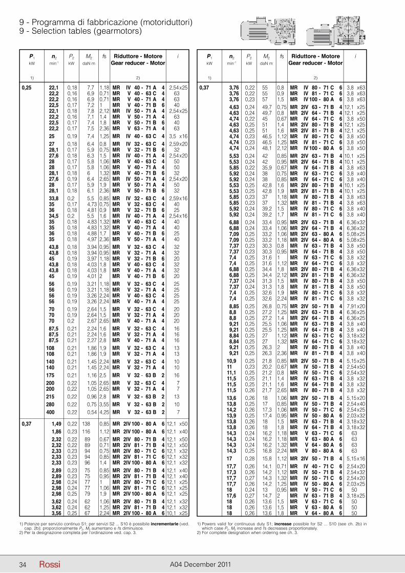
P1 n2 P2 M2 fs Riduttore - Motore i kW min-1 kW daN m Gear reducer - Motor
1) 2)
P1 n2 P2 M2 fs Riduttore - Motore i kW min-1 kW daN m Gear reducer - Motor
1) 2)
34 A04 December 2011
9 - Programma di fabbricazione (motoriduttori)9 - Selection tables (gearmotors)
P1 n2 P2 M2 fs Riduttore - Motore i kW min-1 kW daN m Gear reducer - Motor
1) 2)
1) Potenze per servizio continuo S1; per servizi S2 ... S10 è possibile incrementarle (ved. cap. 2b); proporzionalmente P2, M2 aumentano e fs diminuisce.
2) Per la designazione completa per l’ordinazione ved. cap. 3.
1) Powers valid for continuous duty S1; increase possible for S2 ... S10 (see ch. 2b) in which case P2, M2 increase and fs decreases proportionately.
2) For complete designation when ordering see ch. 3.
0,25 22,1 0,18 7,7 1,18 MR IV 40 - 71 A 4 12,54 x 25 22,2 0,16 6,9 0,71 MR V 40 - 63 C 4 63 22,2 0,16 6,9 0,71 MR V 40 - 71 A 4 63 22,5 0,17 7,2 1 MR V 40 - 71 B 6 40 22,1 0,18 7,8 2,12 MR IV 50 - 71 A 4 12,54 x 25 22,2 0,16 7,1 1,4 MR V 50 - 71 A 4 63 22,5 0,17 7,4 1,8 MR V 50 - 71 B 6 40 22,2 0,17 7,5 2,36 MR V 63 - 71 A 4 63 25 0,19 7,4 1,25 MR IV 40 - 63 C 4 13,5 x 16 27 0,18 6,4 0,8 MR IV 32 - 63 C 4 12,59 x 20 28,1 0,17 5,9 0,75 MR V 32 - 71 B 6 32 27,6 0,18 6,3 1,5 MR IV 40 - 71 A 4 12,54 x 20 28 0,17 5,8 1,06 MR V 40 - 63 C 4 50 28 0,17 5,8 1,06 MR V 40 - 71 A 4 50 28,1 0,18 6 1,32 MR V 40 - 71 B 6 32 27,6 0,19 6,4 2,65 MR IV 50 - 71 A 4 12,54 x 20 28 0,17 5,9 1,9 MR V 50 - 71 A 4 50 28,1 0,18 6,1 2,36 MR V 50 - 71 B 6 32 33,8 0,2 5,5 0,85 MR IV 32 - 63 C 4 12,59 x 16 35 0,17 4,73 0,75 MR V 32 - 63 C 4 40 36 0,18 4,81 0,9 MR V 32 - 71 B 6 25 34,5 0,2 5,5 1,6 MR IV 40 - 71 A 4 12,54 x 16 35 0,18 4,83 1,32 MR V 40 - 63 C 4 40 35 0,18 4,83 1,32 MR V 40 - 71 A 4 40 36 0,18 4,88 1,7 MR V 40 - 71 B 6 25 35 0,18 4,97 2,36 MR V 50 - 71 A 4 40 43,8 0,18 3,94 0,95 MR V 32 - 63 C 4 32 43,8 0,18 3,94 0,95 MR V 32 - 71 A 4 32 45 0,19 3,97 1,18 MR V 32 - 71 B 6 20 43,8 0,18 4,03 1,8 MR V 40 - 63 C 4 32 43,8 0,18 4,03 1,8 MR V 40 - 71 A 4 32 45 0,19 4,01 2 MR V 40 - 71 B 6 20 56 0,19 3,21 1,18 MR V 32 - 63 C 4 25 56 0,19 3,21 1,18 MR V 32 - 71 A 4 25 56 0,19 3,26 2,24 MR V 40 - 63 C 4 25 56 0,19 3,26 2,24 MR V 40 - 71 A 4 25 70 0,19 2,64 1,5 MR V 32 - 63 C 4 20 70 0,19 2,64 1,5 MR V 32 - 71 A 4 20 70 0,2 2,67 2,65 MR V 40 - 71 A 4 20 87,5 0,21 2,24 1,6 MR V 32 - 63 C 4 16 87,5 0,21 2,24 1,6 MR V 32 - 71 A 4 16 87,5 0,21 2,27 2,8 MR V 40 - 71 A 4 16 108 0,21 1,86 1,9 MR V 32 - 63 C 4 13 108 0,21 1,86 1,9 MR V 32 - 71 A 4 13 140 0,21 1,45 2,24 MR V 32 - 63 C 4 10 140 0,21 1,45 2,24 MR V 32 - 71 A 4 10 175 0,21 1,16 2,5 MR V 32 - 63 B 2 16 200 0,22 1,05 2,65 MR V 32 - 63 C 4 7 200 0,22 1,05 2,65 MR V 32 - 71 A 4 7 215 0,22 0,96 2,8 MR V 32 - 63 B 2 13 280 0,22 0,75 3,55 MR V 32 - 63 B 2 10 400 0,22 0,54 4,25 MR V 32 - 63 B 2 7
0,37 1,49 0,22 138 0,85 MR 2IV 100 - 80 A 6 12,1 x 50 1,86 0,23 116 1,12 MR 2IV 100 - 80 A 6 12,1 x 40 2,32 0,22 89 0,67 MR 2IV 80 - 71 B 4 12,1 x 50 2,32 0,22 89 0,71 MR 2IV 81 - 71 B 4 12,1 x 50 2,33 0,23 94 0,75 MR 2IV 80 - 71 C 6 12,1 x 32 2,33 0,23 94 0,85 MR 2IV 81 - 71 C 6 12,1 x 32 2,33 0,23 96 1,4 MR 2IV 100 - 80 A 6 12,1 x 32 2,89 0,23 75 0,85 MR 2IV 80 - 71 B 4 12,1 x 40 2,89 0,23 75 0,95 MR 2IV 81 - 71 B 4 12,1 x 40 2,98 0,24 77 1 MR 2IV 80 - 71 C 6 12,1 x 25 2,98 0,24 77 1,06 MR 2IV 81 - 71 C 6 12,1 x 25 2,98 0,25 79 1,9 MR 2IV 100 - 80 A 6 12,1 x 25 3,62 0,24 62 1,06 MR 2IV 80 - 71 B 4 12,1 x 32 3,62 0,24 62 1,25 MR 2IV 81 - 71 B 4 12,1 x 32 3,56 0,25 67 2,24 MR 2IV 100 - 80 A 6 10,1 x 25
P1 n2 P2 M2 fs Riduttore - Motore i kW min-1 kW daN m Gear reducer - Motor
1) 2)
0,37 3,76 0,22 55 0,8 MR IV 80 - 71 C 6 13,8 x 63 3,76 0,22 55 0,9 MR IV 81 - 71 C 6 13,8 x 63 3,76 0,23 57 1,5 MR IV 100 - 80 A 6 13,8 x 63 4,63 0,24 49,7 0,75 MR 2IV 63 - 71 B 4 12,1 x 25 4,63 0,24 49,7 0,8 MR 2IV 64 - 71 B 4 12,1 x 25 4,74 0,22 45 0,67 MR IV 64 - 71 C 6 13,8 x 50 4,63 0,25 51 1,4 MR 2IV 80 - 71 B 4 12,1 x 25 4,63 0,25 51 1,6 MR 2IV 81 - 71 B 4 12,1 x 25 4,74 0,23 46,5 1,12 MR IV 80 - 71 C 6 13,8 x 50 4,74 0,23 46,5 1,25 MR IV 81 - 71 C 6 13,8 x 50 4,74 0,24 48,1 2,12 MR IV 100 - 80 A 6 13,8 x 50 5,53 0,24 42 0,85 MR 2IV 63 - 71 B 4 10,1 x 25 5,53 0,24 42 0,95 MR 2IV 64 - 71 B 4 10,1 x 25 5,85 0,22 35,9 0,67 MR IV 64 - 71 B 4 13,8 x 63 5,92 0,24 38 0,75 MR IV 63 - 71 C 6 13,8 x 40 5,92 0,24 38 0,85 MR IV 64 - 71 C 6 13,8 x 40 5,53 0,25 42,8 1,6 MR 2IV 80 - 71 B 4 10,1 x 25 5,53 0,25 42,8 1,9 MR 2IV 81 - 71 B 4 10,1 x 25 5,85 0,23 37 1,18 MR IV 80 - 71 B 4 13,8 x 63 5,85 0,23 37 1,32 MR IV 81 - 71 B 4 13,8 x 63 5,92 0,24 39,2 1,5 MR IV 80 - 71 C 6 13,8 x 40 5,92 0,24 39,2 1,7 MR IV 81 - 71 C 6 13,8 x 40 6,88 0,24 33,4 0,95 MR 2IV 63 - 71 B 4 16,36 x 32 6,88 0,24 33,4 1,06 MR 2IV 64 - 71 B 4 16,36 x 32 7,09 0,25 33,2 1,06 MR 2IV 63 - 80 A 6 15,08 x 25 7,09 0,25 33,2 1,18 MR 2IV 64 - 80 A 6 15,08 x 25 7,37 0,23 30,3 0,8 MR IV 63 - 71 B 4 13,8 x 50 7,37 0,23 30,3 0,95 MR IV 64 - 71 B 4 13,8 x 50 7,4 0,25 31,6 1 MR IV 63 - 71 C 6 13,8 x 32 7,4 0,25 31,6 1,12 MR IV 64 - 71 C 6 13,8 x 32 6,88 0,25 34,4 1,8 MR 2IV 80 - 71 B 4 16,36 x 32 6,88 0,25 34,4 2,12 MR 2IV 81 - 71 B 4 16,36 x 32 7,37 0,24 31,3 1,5 MR IV 80 - 71 B 4 13,8 x 50 7,37 0,24 31,3 1,8 MR IV 81 - 71 B 4 13,8 x 50 7,4 0,25 32,6 1,9 MR IV 80 - 71 C 6 13,8 x 32 7,4 0,25 32,6 2,24 MR IV 81 - 71 C 6 13,8 x 32 8,85 0,25 26,8 0,75 MR 2IV 50 - 71 B 4 17,91 x 20 8,8 0,25 27,2 1,25 MR 2IV 63 - 71 B 4 16,36 x 25 8,8 0,25 27,2 1,4 MR 2IV 64 - 71 B 4 16,36 x 25 9,21 0,25 25,5 1,06 MR IV 63 - 71 B 4 13,8 x 40 9,21 0,25 25,5 1,25 MR IV 64 - 71 B 4 13,8 x 40 8,84 0,25 27 1,12 MR IV 63 - 71 C 6 13,18 x 32 8,84 0,25 27 1,32 MR IV 64 - 71 C 6 13,18 x 32 9,21 0,25 26,3 2 MR IV 80 - 71 B 4 13,8 x 40 9,21 0,25 26,3 2,36 MR IV 81 - 71 B 4 13,8 x 40 10,9 0,25 21,8 0,85 MR 2IV 50 - 71 B 4 15,15 x 25 11 0,23 20,2 0,67 MR IV 50 - 71 B 4 12,54 x 50 11,1 0,25 21,2 0,8 MR IV 50 - 71 C 6 12,54 x 32 11,5 0,25 21,1 1,4 MR IV 63 - 71 B 4 13,8 x 32 11,5 0,25 21,1 1,6 MR IV 64 - 71 B 4 13,8 x 32 11,5 0,26 21,7 2,65 MR IV 80 - 71 B 4 13,8 x 32 13,6 0,26 18 1,06 MR 2IV 50 - 71 B 4 15,15 x 20 13,8 0,25 17 0,85 MR IV 50 - 71 B 4 12,54 x 40 14,2 0,26 17,3 1,06 MR IV 50 - 71 C 6 12,54 x 25 13,9 0,25 17,4 0,95 MR IV 50 - 80 A 6 12,03 x 32 13,8 0,26 18 1,5 MR IV 63 - 71 B 4 13,18 x 32 13,8 0,26 18 1,8 MR IV 64 - 71 B 4 13,18 x 32 14,3 0,24 16,2 1,18 MR V 63 - 71 C 6 63 14,3 0,24 16,2 1,18 MR V 63 - 80 A 6 63 14,3 0,24 16,2 1,32 MR V 64 - 80 A 6 63 14,3 0,25 16,8 2,24 MR V 80 - 80 A 6 63 17 0,28 15,8 1,12 MR 2IV 50 - 71 B 4 15,15 x 16 17,7 0,26 14,1 0,71 MR IV 40 - 71 C 6 12,54 x 20 17,3 0,26 14,2 1,12 MR IV 50 - 71 B 4 12,54 x 32 17,7 0,27 14,3 1,32 MR IV 50 - 71 C 6 12,54 x 20 17,7 0,26 14,2 1,25 MR IV 50 - 80 A 6 12,03 x 25 18 0,24 13 0,95 MR V 50 - 71 C 6 50 17,6 0,27 14,7 2 MR IV 63 - 71 B 4 13,18 x 25 18 0,26 13,6 1,5 MR V 63 - 71 C 6 50 18 0,26 13,6 1,5 MR V 63 - 80 A 6 50 18 0,26 13,6 1,8 MR V 64 - 80 A 6 50
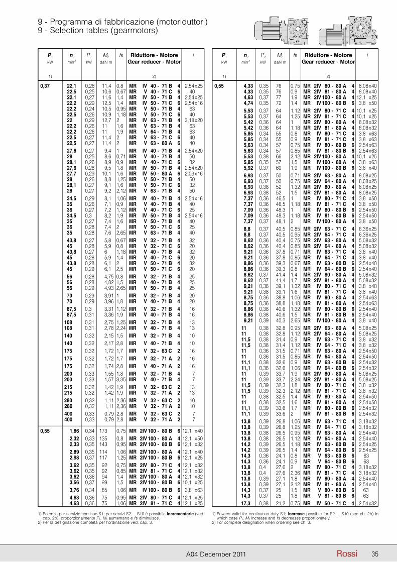
P1 n2 P2 M2 fs Riduttore - Motore i kW min-1 kW daN m Gear reducer - Motor
1) 2)
P1 n2 P2 M2 fs Riduttore - Motore i kW min-1 kW daN m Gear reducer - Motor
1) 2)
35A04 December 2011
9 - Programma di fabbricazione (motoriduttori)9 - Selection tables (gearmotors)
P1 n2 P2 M2 fs Riduttore - Motore i kW min-1 kW daN m Gear reducer - Motor
1) 2)
1) Potenze per servizio continuo S1; per servizi S2 ... S10 è possibile incrementarle (ved. cap. 2b); proporzionalmente P2, M2 aumentano e fs diminuisce.
2) Per la designazione completa per l’ordinazione ved. cap. 3.
1) Powers valid for continuous duty S1; increase possible for S2 ... S10 (see ch. 2b) in which case P2, M2 increase and fs decreases proportionately.
2) For complete designation when ordering see ch. 3.
0,37 22,1 0,26 11,4 0,8 MR IV 40 - 71 B 4 12,54 x 25 22,5 0,25 10,6 0,67 MR V 40 - 71 C 6 40 22,1 0,27 11,6 1,4 MR IV 50 - 71 B 4 12,54 x 25 22,2 0,29 12,5 1,4 MR IV 50 - 71 C 6 12,54 x 16 22,2 0,24 10,5 0,95 MR V 50 - 71 B 4 63 22,5 0,26 10,9 1,18 MR V 50 - 71 C 6 40 22 0,29 12,7 2 MR IV 63 - 71 B 4 13,18 x 20 22,2 0,26 11 1,6 MR V 63 - 71 B 4 63 22,2 0,26 11 1,9 MR V 64 - 71 B 4 63 22,5 0,27 11,4 2 MR V 63 - 71 C 6 40 22,5 0,27 11,4 2 MR V 63 - 80 A 6 40 27,6 0,27 9,4 1 MR IV 40 - 71 B 4 12,54 x 20 28 0,25 8,6 0,71 MR V 40 - 71 B 4 50 28,1 0,26 8,9 0,9 MR V 40 - 71 C 6 32 27,6 0,28 9,5 1,8 MR IV 50 - 71 B 4 12,54 x 20 27,7 0,29 10,1 1,6 MR IV 50 - 80 A 6 12,03 x 16 28 0,26 8,8 1,25 MR V 50 - 71 B 4 50 28,1 0,27 9,1 1,6 MR V 50 - 71 C 6 32 28 0,27 9,2 2,12 MR V 63 - 71 B 4 50 34,5 0,29 8,1 1,06 MR IV 40 - 71 B 4 12,54 x 16 35 0,26 7,1 0,9 MR V 40 - 71 B 4 40 36 0,27 7,2 1,12 MR V 40 - 71 C 6 25 34,5 0,3 8,2 1,9 MR IV 50 - 71 B 4 12,54 x 16 35 0,27 7,4 1,6 MR V 50 - 71 B 4 40 36 0,28 7,4 2 MR V 50 - 71 C 6 25 35 0,28 7,6 2,65 MR V 63 - 71 B 4 40 43,8 0,27 5,8 0,67 MR V 32 - 71 B 4 32 45 0,28 5,9 0,8 MR V 32 - 71 C 6 20 43,8 0,27 6 1,18 MR V 40 - 71 B 4 32 45 0,28 5,9 1,4 MR V 40 - 71 C 6 20 43,8 0,28 6,1 2 MR V 50 - 71 B 4 32 45 0,29 6,1 2,5 MR V 50 - 71 C 6 20 56 0,28 4,75 0,8 MR V 32 - 71 B 4 25 56 0,28 4,82 1,5 MR V 40 - 71 B 4 25 56 0,29 4,93 2,65 MR V 50 - 71 B 4 25 70 0,29 3,91 1 MR V 32 - 71 B 4 20 70 0,29 3,96 1,8 MR V 40 - 71 B 4 20 87,5 0,3 3,31 1,12 MR V 32 - 71 B 4 16 87,5 0,31 3,36 1,9 MR V 40 - 71 B 4 16 108 0,31 2,75 1,25 MR V 32 - 71 B 4 13 108 0,31 2,78 2,24 MR V 40 - 71 B 4 13 140 0,32 2,15 1,5 MR V 32 - 71 B 4 10 140 0,32 2,17 2,8 MR V 40 - 71 B 4 10 175 0,32 1,72 1,7 MR V 32 - 63 C 2 16 175 0,32 1,72 1,7 MR V 32 - 71 A 2 16 175 0,32 1,74 2,8 MR V 40 - 71 A 2 16 200 0,33 1,55 1,8 MR V 32 - 71 B 4 7 200 0,33 1,57 3,35 MR V 40 - 71 B 4 7 215 0,32 1,42 1,9 MR V 32 - 63 C 2 13 215 0,32 1,42 1,9 MR V 32 - 71 A 2 13 280 0,32 1,11 2,36 MR V 32 - 63 C 2 10 280 0,32 1,11 2,36 MR V 32 - 71 A 2 10 400 0,33 0,79 2,8 MR V 32 - 63 C 2 7 400 0,33 0,79 2,8 MR V 32 - 71 A 2 7
0,55 1,86 0,34 173 0,75 MR 2IV 100 - 80 B 6 12,1 x 40 2,32 0,33 135 0,8 MR 2IV 100 - 80 A 4 12,1 x 50 2,33 0,35 143 0,95 MR 2IV 100 - 80 B 6 12,1 x 32 2,89 0,35 114 1,06 MR 2IV 100 - 80 A 4 12,1 x 40 2,98 0,37 117 1,25 MR 2IV 100 - 80 B 6 12,1 x 25 3,62 0,35 92 0,75 MR 2IV 80 - 71 C 4 12,1 x 32 3,62 0,35 92 0,85 MR 2IV 81 - 71 C 4 12,1 x 32 3,62 0,36 94 1,4 MR 2IV 100 - 80 A 4 12,1 x 32 3,56 0,37 99 1,5 MR 2IV 100 - 80 B 6 10,1 x 25 3,76 0,34 85 1,06 MR IV 100 - 80 B 6 23,8 x 63 4,63 0,36 75 0,95 MR 2IV 80 - 71 C 4 12,1 x 25 4,63 0,36 75 1,06 MR 2IV 81 - 71 C 4 12,1 x 25
P1 n2 P2 M2 fs Riduttore - Motore i kW min-1 kW daN m Gear reducer - Motor
1) 2)
0,55 4,33 0,35 76 0,75 MR 2IV 80 - 80 A 4 28,08 x 40 4,33 0,35 76 0,9 MR 2IV 81 - 80 A 4 28,08 x 40 4,63 0,37 77 1,9 MR 2IV 100 - 80 A 4 12,1 x 25 4,74 0,35 72 1,4 MR IV 100 - 80 B 6 23,8 x 50 5,53 0,37 64 1,12 MR 2IV 80 - 71 C 4 10,1 x 25 5,53 0,37 64 1,25 MR 2IV 81 - 71 C 4 10,1 x 25 5,42 0,36 64 1 MR 2IV 80 - 80 A 4 28,08 x 32 5,42 0,36 64 1,18 MR 2IV 81 - 80 A 4 28,08 x 32 5,85 0,34 55 0,8 MR IV 80 - 71 C 4 23,8 x 63 5,85 0,34 55 0,9 MR IV 81 - 71 C 4 23,8 x 63 5,63 0,34 57 0,75 MR IV 80 - 80 B 6 22,54 x 63 5,63 0,34 57 0,85 MR IV 81 - 80 B 6 22,54 x 63 5,53 0,38 66 2,12 MR 2IV 100 - 80 A 4 10,1 x 25 5,85 0,35 57 1,5 MR IV 100 - 80 A 4 23,8 x 63 5,92 0,37 60 1,9 MR IV 100 - 80 B 6 23,8 x 40 6,93 0,37 50 0,71 MR 2IV 63 - 80 A 4 28,08 x 25 6,93 0,37 50 0,75 MR 2IV 64 - 80 A 4 28,08 x 25 6,93 0,38 52 1,32 MR 2IV 80 - 80 A 4 28,08 x 25 6,93 0,38 52 1,5 MR 2IV 81 - 80 A 4 28,08 x 25 7,37 0,36 46,5 1 MR IV 80 - 71 C 4 23,8 x 50 7,37 0,36 46,5 1,18 MR IV 81 - 71 C 4 23,8 x 50 7,09 0,36 48,3 1 MR IV 80 - 80 B 6 22,54 x 50 7,09 0,36 48,3 1,18 MR IV 81 - 80 B 6 22,54 x 50 7,37 0,37 48,1 2 MR IV 100 - 80 A 4 23,8 x 50 8,8 0,37 40,5 0,85 MR 2IV 63 - 71 C 4 26,36 x 25 8,8 0,37 40,5 0,95 MR 2IV 64 - 71 C 4 26,36 x 25 8,62 0,36 40,4 0,75 MR 2IV 63 - 80 A 4 25,08 x 32 8,62 0,36 40,4 0,85 MR 2IV 64 - 80 A 4 25,08 x 32 9,21 0,36 37,8 0,71 MR IV 63 - 71 C 4 23,8 x 40 9,21 0,36 37,8 0,85 MR IV 64 - 71 C 4 23,8 x 40 8,86 0,36 39,3 0,67 MR IV 63 - 80 B 6 22,54 x 40 8,86 0,36 39,3 0,8 MR IV 64 - 80 B 6 22,54 x 40 8,62 0,37 41,4 1,4 MR 2IV 80 - 80 A 4 25,08 x 32 8,62 0,37 41,4 1,7 MR 2IV 81 - 80 A 4 25,08 x 32 9,21 0,38 39,1 1,32 MR IV 80 - 71 C 4 23,8 x 40 9,21 0,38 39,1 1,6 MR IV 81 - 71 C 4 23,8 x 40 8,75 0,36 38,8 1,06 MR IV 80 - 80 A 4 22,54 x 63 8,75 0,36 38,8 1,18 MR IV 81 - 80 A 4 22,54 x 63 8,86 0,38 40,6 1,32 MR IV 80 - 80 B 6 22,54 x 40 8,86 0,38 40,6 1,5 MR IV 81 - 80 B 6 22,54 x 40 9,21 0,39 40,3 2,65 MR IV 100 - 80 A 4 23,8 x 40 11 0,38 32,8 0,95 MR 2IV 63 - 80 A 4 25,08 x 25 11 0,38 32,8 1,12 MR 2IV 64 - 80 A 4 25,08 x 25 11,5 0,38 31,4 0,9 MR IV 63 - 71 C 4 23,8 x 32 11,5 0,38 31,4 1,12 MR IV 64 - 71 C 4 23,8 x 32 11 0,36 31,5 0,71 MR IV 63 - 80 A 4 22,54 x 50 11 0,36 31,5 0,85 MR IV 64 - 80 A 4 22,54 x 50 11,1 0,38 32,6 0,9 MR IV 63 - 80 B 6 22,54 x 32 11,1 0,38 32,6 1,06 MR IV 64 - 80 B 6 22,54 x 32 11 0,39 33,7 1,9 MR 2IV 80 - 80 A 4 25,08 x 25 11 0,39 33,7 2,24 MR 2IV 81 - 80 A 4 25,08 x 25 11,5 0,39 32,3 1,8 MR IV 80 - 71 C 4 23,8 x 32 11,5 0,39 32,3 2,12 MR IV 81 - 71 C 4 23,8 x 32 11 0,38 32,5 1,4 MR IV 80 - 80 A 4 22,54 x 50 11 0,38 32,5 1,6 MR IV 81 - 80 A 4 22,54 x 50 11,1 0,39 33,6 1,7 MR IV 80 - 80 B 6 22,54 x 32 11,1 0,39 33,6 2 MR IV 81 - 80 B 6 22,54 x 32 13,8 0,39 26,8 1,06 MR IV 63 - 71 C 4 23,18 x 32 13,8 0,39 26,8 1,25 MR IV 64 - 71 C 4 23,18 x 32 13,8 0,38 26,5 0,95 MR IV 63 - 80 A 4 22,54 x 40 13,8 0,38 26,5 1,12 MR IV 64 - 80 A 4 22,54 x 40 14,2 0,39 26,5 1,18 MR IV 63 - 80 B 6 22,54 x 25 14,2 0,39 26,5 1,4 MR IV 64 - 80 B 6 22,54 x 25 14,3 0,36 24,1 0,8 MR V 63 - 80 B 6 63 14,3 0,36 24,1 0,9 MR V 64 - 80 B 6 63 13,8 0,4 27,6 2 MR IV 80 - 71 C 4 23,18 x 32 13,8 0,4 27,6 2,36 MR IV 81 - 71 C 4 23,18 x 32 13,8 0,39 27,1 1,8 MR IV 80 - 80 A 4 22,54 x 40 13,8 0,39 27,1 2,12 MR IV 81 - 80 A 4 22,54 x 40 14,3 0,37 25 1,5 MR V 80 - 80 B 6 2 63 14,3 0,37 25 1,8 MR V 81 - 80 B 6 2 63 17,3 0,38 21,2 0,75 MR IV 50 - 71 C 4 22,54 x 32
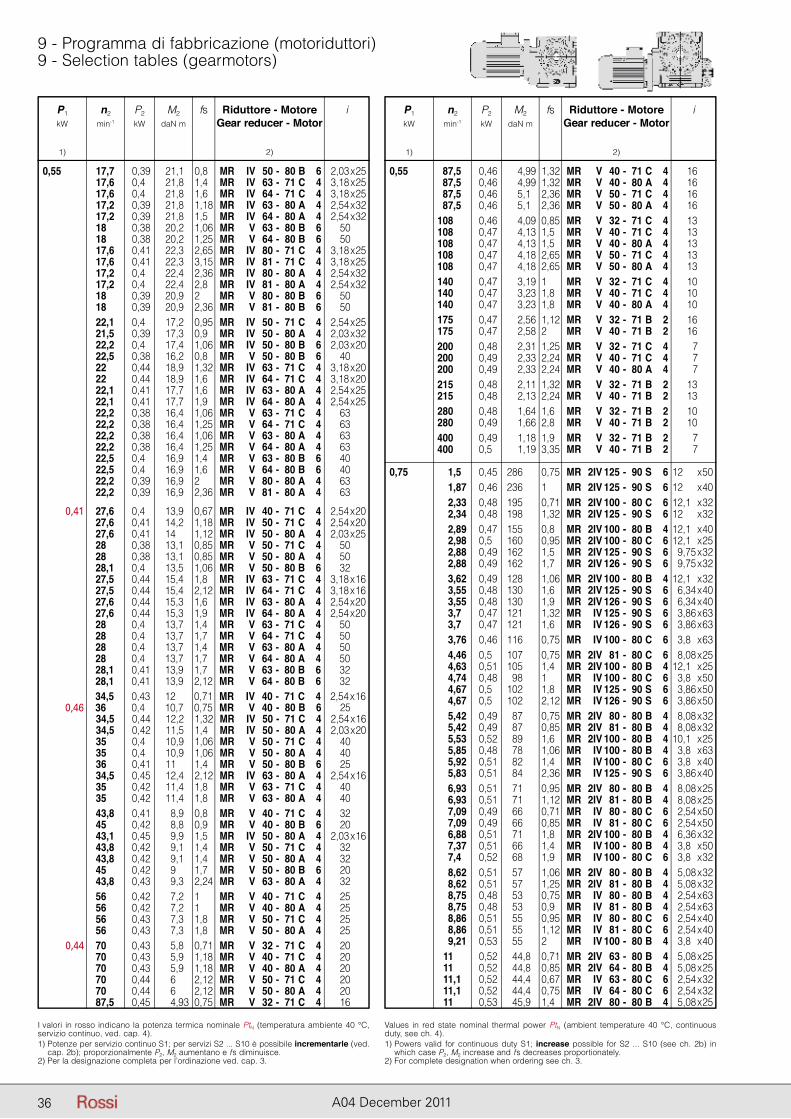
P1 n2 P2 M2 fs Riduttore - Motore i kW min-1 kW daN m Gear reducer - Motor
1) 2)
P1 n2 P2 M2 fs Riduttore - Motore i kW min-1 kW daN m Gear reducer - Motor
1) 2)
36 A04 December 2011
9 - Programma di fabbricazione (motoriduttori)9 - Selection tables (gearmotors)
P1 n2 P2 M2 fs Riduttore - Motore i kW min-1 kW daN m Gear reducer - Motor
1) 2)
I valori in rosso indicano la potenza termica nominale PtN (temperatura ambiente 40 °C, servizio continuo, ved. cap. 4).1) Potenze per servizio continuo S1; per servizi S2 ... S10 è possibile incrementarle (ved.
cap. 2b); proporzionalmente P2, M2 aumentano e fs diminuisce.2) Per la designazione completa per l’ordinazione ved. cap. 3.
Values in red state nominal thermal power PtN (ambient temperature 40 °C, continuous duty, see ch. 4).1) Powers valid for continuous duty S1; increase possible for S2 ... S10 (see ch. 2b) in
which case P2, M2 increase and fs decreases proportionately.2) For complete designation when ordering see ch. 3.
0,55 17,7 0,39 21,1 0,8 MR IV 50 - 80 B 6 22,03 x 25 17,6 0,4 21,8 1,4 MR IV 63 - 71 C 4 23,18 x 25 17,6 0,4 21,8 1,6 MR IV 64 - 71 C 4 23,18 x 25 17,2 0,39 21,8 1,18 MR IV 63 - 80 A 4 22,54 x 32 17,2 0,39 21,8 1,5 MR IV 64 - 80 A 4 22,54 x 32 18 0,38 20,2 1,06 MR V 63 - 80 B 6 50 18 0,38 20,2 1,25 MR V 64 - 80 B 6 50 17,6 0,41 22,3 2,65 MR IV 80 - 71 C 4 23,18 x 25 17,6 0,41 22,3 3,15 MR IV 81 - 71 C 4 23,18 x 25 17,2 0,4 22,4 2,36 MR IV 80 - 80 A 4 22,54 x 32 17,2 0,4 22,4 2,8 MR IV 81 - 80 A 4 22,54 x 32 18 0,39 20,9 2 MR V 80 - 80 B 6 50 18 0,39 20,9 2,36 MR V 81 - 80 B 6 50 22,1 0,4 17,2 0,95 MR IV 50 - 71 C 4 22,54 x 25 21,5 0,39 17,3 0,9 MR IV 50 - 80 A 4 22,03 x 32 22,2 0,4 17,4 1,06 MR IV 50 - 80 B 6 22,03 x 20 22,5 0,38 16,2 0,8 MR V 50 - 80 B 6 40 22 0,44 18,9 1,32 MR IV 63 - 71 C 4 23,18 x 20 22 0,44 18,9 1,6 MR IV 64 - 71 C 4 23,18 x 20 22,1 0,41 17,7 1,6 MR IV 63 - 80 A 4 22,54 x 25 22,1 0,41 17,7 1,9 MR IV 64 - 80 A 4 22,54 x 25 22,2 0,38 16,4 1,06 MR V 63 - 71 C 4 63 22,2 0,38 16,4 1,25 MR V 64 - 71 C 4 63 22,2 0,38 16,4 1,06 MR V 63 - 80 A 4 63 22,2 0,38 16,4 1,25 MR V 64 - 80 A 4 63 22,5 0,4 16,9 1,4 MR V 63 - 80 B 6 40 22,5 0,4 16,9 1,6 MR V 64 - 80 B 6 40 22,2 0,39 16,9 2 MR V 80 - 80 A 4 63 22,2 0,39 16,9 2,36 MR V 81 - 80 A 4 63
0,41 27,6 0,4 13,9 0,67 MR IV 40 - 71 C 4 22,54 x 20 27,6 0,41 14,2 1,18 MR IV 50 - 71 C 4 22,54 x 20 27,6 0,41 14 1,12 MR IV 50 - 80 A 4 22,03 x 25 28 0,38 13,1 0,85 MR V 50 - 71 C 4 50 28 0,38 13,1 0,85 MR V 50 - 80 A 4 50 28,1 0,4 13,5 1,06 MR V 50 - 80 B 6 32 27,5 0,44 15,4 1,8 MR IV 63 - 71 C 4 23,18 x 16 27,5 0,44 15,4 2,12 MR IV 64 - 71 C 4 23,18 x 16 27,6 0,44 15,3 1,6 MR IV 63 - 80 A 4 22,54 x 20 27,6 0,44 15,3 1,9 MR IV 64 - 80 A 4 22,54 x 20 28 0,4 13,7 1,4 MR V 63 - 71 C 4 50 28 0,4 13,7 1,7 MR V 64 - 71 C 4 50 28 0,4 13,7 1,4 MR V 63 - 80 A 4 50 28 0,4 13,7 1,7 MR V 64 - 80 A 4 50 28,1 0,41 13,9 1,7 MR V 63 - 80 B 6 32 28,1 0,41 13,9 2,12 MR V 64 - 80 B 6 32 34,5 0,43 12 0,71 MR IV 40 - 71 C 4 22,54 x 16 0,46 36 0,4 10,7 0,75 MR V 40 - 80 B 6 25 34,5 0,44 12,2 1,32 MR IV 50 - 71 C 4 22,54 x 16 34,5 0,42 11,5 1,4 MR IV 50 - 80 A 4 22,03 x 20 35 0,4 10,9 1,06 MR V 50 - 71 C 4 40 35 0,4 10,9 1,06 MR V 50 - 80 A 4 40 36 0,41 11 1,4 MR V 50 - 80 B 6 25 34,5 0,45 12,4 2,12 MR IV 63 - 80 A 4 12,54 x 16 35 0,42 11,4 1,8 MR V 63 - 71 C 4 40 35 0,42 11,4 1,8 MR V 63 - 80 A 4 40 43,8 0,41 8,9 0,8 MR V 40 - 71 C 4 32 45 0,42 8,8 0,9 MR V 40 - 80 B 6 20 43,1 0,45 9,9 1,5 MR IV 50 - 80 A 4 12,03 x 16 43,8 0,42 9,1 1,4 MR V 50 - 71 C 4 32 43,8 0,42 9,1 1,4 MR V 50 - 80 A 4 32 45 0,42 9 1,7 MR V 50 - 80 B 6 20 43,8 0,43 9,3 2,24 MR V 63 - 80 A 4 32 56 0,42 7,2 1 MR V 40 - 71 C 4 25 56 0,42 7,2 1 MR V 40 - 80 A 4 25 56 0,43 7,3 1,8 MR V 50 - 71 C 4 25 56 0,43 7,3 1,8 MR V 50 - 80 A 4 25 0,44 70 0,43 5,8 0,71 MR V 32 - 71 C 4 20 70 0,43 5,9 1,18 MR V 40 - 71 C 4 20 70 0,43 5,9 1,18 MR V 40 - 80 A 4 20 70 0,44 6 2,12 MR V 50 - 71 C 4 20 70 0,44 6 2,12 MR V 50 - 80 A 4 20 87,5 0,45 4,93 0,75 MR V 32 - 71 C 4 16
P1 n2 P2 M2 fs Riduttore - Motore i kW min-1 kW daN m Gear reducer - Motor
1) 2)
0,55 87,5 0,46 4,99 1,32 MR V 40 - 71 C 4 16 87,5 0,46 4,99 1,32 MR V 40 - 80 A 4 16 87,5 0,46 5,1 2,36 MR V 50 - 71 C 4 16 87,5 0,46 5,1 2,36 MR V 50 - 80 A 4 16 108 0,46 4,09 0,85 MR V 32 - 71 C 4 13 108 0,47 4,13 1,5 MR V 40 - 71 C 4 13 108 0,47 4,13 1,5 MR V 40 - 80 A 4 13 108 0,47 4,18 2,65 MR V 50 - 71 C 4 13 108 0,47 4,18 2,65 MR V 50 - 80 A 4 13 140 0,47 3,19 1 MR V 32 - 71 C 4 10 140 0,47 3,23 1,8 MR V 40 - 71 C 4 10 140 0,47 3,23 1,8 MR V 40 - 80 A 4 10 175 0,47 2,56 1,12 MR V 32 - 71 B 2 16 175 0,47 2,58 2 MR V 40 - 71 B 2 16 200 0,48 2,31 1,25 MR V 32 - 71 C 4 7 200 0,49 2,33 2,24 MR V 40 - 71 C 4 7 200 0,49 2,33 2,24 MR V 40 - 80 A 4 7 215 0,48 2,11 1,32 MR V 32 - 71 B 2 13 215 0,48 2,13 2,24 MR V 40 - 71 B 2 13 280 0,48 1,64 1,6 MR V 32 - 71 B 2 10 280 0,49 1,66 2,8 MR V 40 - 71 B 2 10 400 0,49 1,18 1,9 MR V 32 - 71 B 2 7 400 0,5 1,19 3,35 MR V 40 - 71 B 2 7
0,75 1,5 0,45 286 0,75 MR 2IV 125 - 90 S 6 12 x 50 1,87 0,46 236 1 MR 2IV 125 - 90 S 6 12 x 40
2,33 0,48 195 0,71 MR 2IV 100 - 80 C 6 12,1 x 32 2,34 0,48 198 1,32 MR 2IV 125 - 90 S 6 12 x 32 2,89 0,47 155 0,8 MR 2IV 100 - 80 B 4 12,1 x 40 2,98 0,5 160 0,95 MR 2IV 100 - 80 C 6 12,1 x 25 2,88 0,49 162 1,5 MR 2IV 125 - 90 S 6 29,75 x 32 2,88 0,49 162 1,7 MR 2IV 126 - 90 S 6 29,75 x 32 3,62 0,49 128 1,06 MR 2IV 100 - 80 B 4 12,1 x 32 3,55 0,48 130 1,6 MR 2IV 125 - 90 S 6 26,34 x 40 3,55 0,48 130 1,9 MR 2IV 126 - 90 S 6 26,34 x 40 3,7 0,47 121 1,32 MR IV 125 - 90 S 6 23,86 x 63 3,7 0,47 121 1,6 MR IV 126 - 90 S 6 23,86 x 63 3,76 0,46 116 0,75 MR IV 100 - 80 C 6 23,8 x 63 4,46 0,5 107 0,75 MR 2IV 81 - 80 C 6 28,08 x 25 4,63 0,51 105 1,4 MR 2IV 100 - 80 B 4 12,1 x 25 4,74 0,48 98 1 MR IV 100 - 80 C 6 23,8 x 50 4,67 0,5 102 1,8 MR IV 125 - 90 S 6 23,86 x 50 4,67 0,5 102 2,12 MR IV 126 - 90 S 6 23,86 x 50 5,42 0,49 87 0,75 MR 2IV 80 - 80 B 4 28,08 x 32 5,42 0,49 87 0,85 MR 2IV 81 - 80 B 4 28,08 x 32 5,53 0,52 89 1,6 MR 2IV 100 - 80 B 4 10,1 x 25 5,85 0,48 78 1,06 MR IV 100 - 80 B 4 23,8 x 63 5,92 0,51 82 1,4 MR IV 100 - 80 C 6 23,8 x 40 5,83 0,51 84 2,36 MR IV 125 - 90 S 6 23,86 x 40 6,93 0,51 71 0,95 MR 2IV 80 - 80 B 4 28,08 x 25 6,93 0,51 71 1,12 MR 2IV 81 - 80 B 4 28,08 x 25 7,09 0,49 66 0,71 MR IV 80 - 80 C 6 22,54 x 50 7,09 0,49 66 0,85 MR IV 81 - 80 C 6 22,54 x 50 6,88 0,51 71 1,8 MR 2IV 100 - 80 B 4 26,36 x 32 7,37 0,51 66 1,4 MR IV 100 - 80 B 4 23,8 x 50 7,4 0,52 68 1,9 MR IV 100 - 80 C 6 23,8 x 32 8,62 0,51 57 1,06 MR 2IV 80 - 80 B 4 25,08 x 32 8,62 0,51 57 1,25 MR 2IV 81 - 80 B 4 25,08 x 32 8,75 0,48 53 0,75 MR IV 80 - 80 B 4 22,54 x 63 8,75 0,48 53 0,9 MR IV 81 - 80 B 4 22,54 x 63 8,86 0,51 55 0,95 MR IV 80 - 80 C 6 22,54 x 40 8,86 0,51 55 1,12 MR IV 81 - 80 C 6 22,54 x 40 9,21 0,53 55 2 MR IV 100 - 80 B 4 23,8 x 40 11 0,52 44,8 0,71 MR 2IV 63 - 80 B 4 25,08 x 25 11 0,52 44,8 0,85 MR 2IV 64 - 80 B 4 25,08 x 25 11,1 0,52 44,4 0,67 MR IV 63 - 80 C 6 22,54 x 32 11,1 0,52 44,4 0,75 MR IV 64 - 80 C 6 22,54 x 32 11 0,53 45,9 1,4 MR 2IV 80 - 80 B 4 25,08 x 25
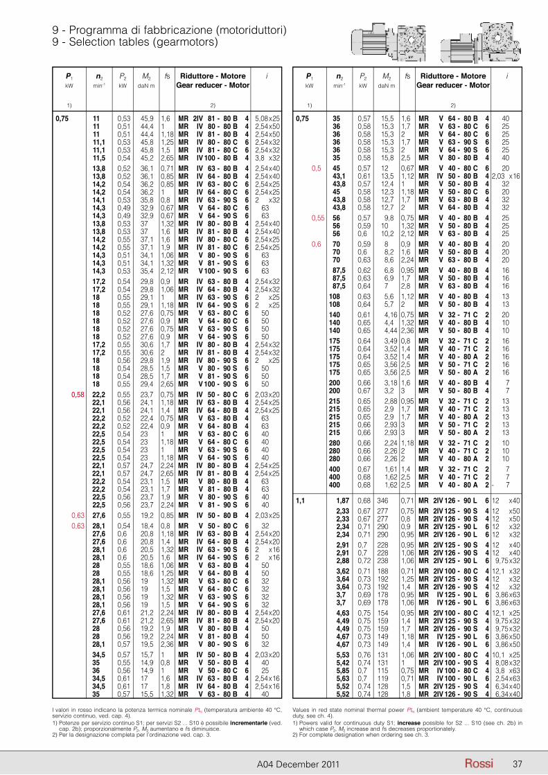
P1 n2 P2 M2 fs Riduttore - Motore i kW min-1 kW daN m Gear reducer - Motor
1) 2)
P1 n2 P2 M2 fs Riduttore - Motore i kW min-1 kW daN m Gear reducer - Motor
1) 2)
37A04 December 2011
9 - Programma di fabbricazione (motoriduttori)9 - Selection tables (gearmotors)
P1 n2 P2 M2 fs Riduttore - Motore i kW min-1 kW daN m Gear reducer - Motor
1) 2)
I valori in rosso indicano la potenza termica nominale PtN (temperatura ambiente 40 °C, servizio continuo, ved. cap. 4).1) Potenze per servizio continuo S1; per servizi S2 ... S10 è possibile incrementarle (ved.
cap. 2b); proporzionalmente P2, M2 aumentano e fs diminuisce.2) Per la designazione completa per l’ordinazione ved. cap. 3.
Values in red state nominal thermal power PtN (ambient temperature 40 °C, continuous duty, see ch. 4).1) Powers valid for continuous duty S1; increase possible for S2 ... S10 (see ch. 2b) in
which case P2, M2 increase and fs decreases proportionately.2) For complete designation when ordering see ch. 3.
0,75 11 0,53 45,9 1,6 MR 2IV 81 - 80 B 4 25,08 x 25 11 0,51 44,4 1 MR IV 80 - 80 B 4 22,54 x 50 11 0,51 44,4 1,18 MR IV 81 - 80 B 4 22,54 x 50 11,1 0,53 45,8 1,25 MR IV 80 - 80 C 6 22,54 x 32 11,1 0,53 45,8 1,5 MR IV 81 - 80 C 6 22,54 x 32 11,5 0,54 45,2 2,65 MR IV 100 - 80 B 4 23,8 x 32 13,8 0,52 36,1 0,71 MR IV 63 - 80 B 4 22,54 x 40 13,8 0,52 36,1 0,85 MR IV 64 - 80 B 4 22,54 x 40 14,2 0,54 36,2 0,85 MR IV 63 - 80 C 6 22,54 x 25 14,2 0,54 36,2 1 MR IV 64 - 80 C 6 22,54 x 25 14,1 0,53 35,8 0,8 MR IV 63 - 90 S 6 22 x 32 14,3 0,49 32,9 0,67 MR V 64 - 80 C 6 63 14,3 0,49 32,9 0,67 MR V 64 - 90 S 6 63 13,8 0,53 37 1,32 MR IV 80 - 80 B 4 22,54 x 40 13,8 0,53 37 1,6 MR IV 81 - 80 B 4 22,54 x 40 14,2 0,55 37,1 1,6 MR IV 80 - 80 C 6 22,54 x 25 14,2 0,55 37,1 1,9 MR IV 81 - 80 C 6 22,54 x 25 14,3 0,51 34,1 1,06 MR V 80 - 90 S 6 63 14,3 0,51 34,1 1,32 MR V 81 - 90 S 6 63 14,3 0,53 35,4 2,12 MR V 100 - 90 S 6 63 17,2 0,54 29,8 0,9 MR IV 63 - 80 B 4 22,54 x 32 17,2 0,54 29,8 1,06 MR IV 64 - 80 B 4 22,54 x 32 18 0,55 29,1 1 MR IV 63 - 90 S 6 22 x 25 18 0,55 29,1 1,18 MR IV 64 - 90 S 6 22 x 25 18 0,52 27,6 0,75 MR V 63 - 80 C 6 50 18 0,52 27,6 0,9 MR V 64 - 80 C 6 50 18 0,52 27,6 0,75 MR V 63 - 90 S 6 50 18 0,52 27,6 0,9 MR V 64 - 90 S 6 50 17,2 0,55 30,6 1,7 MR IV 80 - 80 B 4 22,54 x 32 17,2 0,55 30,6 2 MR IV 81 - 80 B 4 22,54 x 32 18 0,56 29,8 1,9 MR IV 80 - 90 S 6 22 x 25 18 0,54 28,5 1,5 MR V 80 - 90 S 6 50 18 0,54 28,5 1,7 MR V 81 - 90 S 6 50 18 0,55 29,4 2,65 MR V 100 - 90 S 6 50 0,58 22,2 0,55 23,7 0,75 MR IV 50 - 80 C 6 22,03 x 20 22,1 0,56 24,1 1,18 MR IV 63 - 80 B 4 22,54 x 25 22,1 0,56 24,1 1,4 MR IV 64 - 80 B 4 22,54 x 25 22,2 0,52 22,4 0,75 MR V 63 - 80 B 4 63 22,2 0,52 22,4 0,9 MR V 64 - 80 B 4 63 22,5 0,54 23 1 MR V 63 - 80 C 6 40 22,5 0,54 23 1,18 MR V 64 - 80 C 6 40 22,5 0,54 23 1 MR V 63 - 90 S 6 40 22,5 0,54 23 1,18 MR V 64 - 90 S 6 40 22,1 0,57 24,7 2,24 MR IV 80 - 80 B 4 22,54 x 25 22,1 0,57 24,7 2,65 MR IV 81 - 80 B 4 22,54 x 25 22,2 0,54 23,1 1,5 MR V 80 - 80 B 4 63 22,2 0,54 23,1 1,7 MR V 81 - 80 B 4 63 22,5 0,56 23,7 1,9 MR V 80 - 90 S 6 40 22,5 0,56 23,7 2,24 MR V 81 - 90 S 6 40 0,63 27,6 0,55 19,2 0,85 MR IV 50 - 80 B 4 22,03 x 25 0,63 28,1 0,54 18,4 0,8 MR V 50 - 80 C 6 32 27,6 0,6 20,8 1,18 MR IV 63 - 80 B 4 22,54 x 20 27,6 0,6 20,8 1,4 MR IV 64 - 80 B 4 22,54 x 20 28,1 0,6 20,5 1,32 MR IV 63 - 90 S 6 22 x 16 28,1 0,6 20,5 1,6 MR IV 64 - 90 S 6 22 x 16 28 0,55 18,6 1,06 MR V 63 - 80 B 4 50 28 0,55 18,6 1,25 MR V 64 - 80 B 4 50 28,1 0,56 19 1,32 MR V 63 - 80 C 6 32 28,1 0,56 19 1,5 MR V 64 - 80 C 6 32 28,1 0,56 19 1,32 MR V 63 - 90 S 6 32 28,1 0,56 19 1,5 MR V 64 - 90 S 6 32 27,6 0,61 21,2 2,24 MR IV 80 - 80 B 4 22,54 x 20 27,6 0,61 21,2 2,65 MR IV 81 - 80 B 4 22,54 x 20 28 0,56 19,2 1,9 MR V 80 - 80 B 4 50 28 0,56 19,2 2,24 MR V 81 - 80 B 4 50 28,1 0,57 19,5 2,36 MR V 80 - 90 S 6 32 34,5 0,57 15,7 1 MR IV 50 - 80 B 4 22,03 x 20 35 0,55 14,9 0,8 MR V 50 - 80 B 4 40 36 0,56 14,9 1 MR V 50 - 80 C 6 25 34,5 0,61 17 1,6 MR IV 63 - 80 B 4 22,54 x 16 34,5 0,61 17 1,8 MR IV 64 - 80 B 4 22,54 x 16 35 0,57 15,5 1,32 MR V 63 - 80 B 4 40
P1 n2 P2 M2 fs Riduttore - Motore i kW min-1 kW daN m Gear reducer - Motor
1) 2)
0,75 35 0,57 15,5 1,6 MR V 64 - 80 B 4 40 36 0,58 15,3 1,7 MR V 63 - 80 C 6 25 36 0,58 15,3 2 MR V 64 - 80 C 6 25 36 0,58 15,3 1,7 MR V 63 - 90 S 6 25 36 0,58 15,3 2 MR V 64 - 90 S 6 25 35 0,58 15,8 2,5 MR V 80 - 80 B 4 40 0,5 45 0,57 12 0,67 MR V 40 - 80 C 6 20 43,1 0,61 13,5 1,12 MR IV 50 - 80 B 4 2,03 x 16 43,8 0,57 12,4 1 MR V 50 - 80 B 4 32 45 0,58 12,3 1,18 MR V 50 - 80 C 6 20 43,8 0,58 12,7 1,7 MR V 63 - 80 B 4 32 43,8 0,58 12,7 2 MR V 64 - 80 B 4 32 0,55 56 0,57 9,8 0,75 MR V 40 - 80 B 4 25 56 0,59 10 1,32 MR V 50 - 80 B 4 25 56 0,6 10,2 2,12 MR V 63 - 80 B 4 25 0,6 70 0,59 8 0,9 MR V 40 - 80 B 4 20 70 0,6 8,2 1,6 MR V 50 - 80 B 4 20 70 0,63 8,6 2,24 MR V 63 - 80 B 4 20 87,5 0,62 6,8 0,95 MR V 40 - 80 B 4 16 87,5 0,63 6,9 1,7 MR V 50 - 80 B 4 16 87,5 0,64 7 2,8 MR V 63 - 80 B 4 16 108 0,63 5,6 1,12 MR V 40 - 80 B 4 13 108 0,64 5,7 2 MR V 50 - 80 B 4 13 140 0,61 4,16 0,75 MR V 32 - 71 C 2 20 140 0,65 4,4 1,32 MR V 40 - 80 B 4 10 140 0,65 4,44 2,36 MR V 50 - 80 B 4 10 175 0,64 3,49 0,8 MR V 32 - 71 C 2 16 175 0,64 3,52 1,4 MR V 40 - 71 C 2 16 175 0,64 3,52 1,4 MR V 40 - 80 A 2 16 175 0,65 3,56 2,5 MR V 50 - 71 C 2 16 175 0,65 3,56 2,5 MR V 50 - 80 A 2 16 200 0,66 3,18 1,6 MR V 40 - 80 B 4 7 200 0,67 3,2 3 MR V 50 - 80 B 4 7 215 0,65 2,88 0,95 MR V 32 - 71 C 2 13 215 0,65 2,9 1,7 MR V 40 - 71 C 2 13 215 0,65 2,9 1,7 MR V 40 - 80 A 2 13 215 0,66 2,93 3 MR V 50 - 71 C 2 13 215 0,66 2,93 3 MR V 50 - 80 A 2 13 280 0,66 2,24 1,18 MR V 32 - 71 C 2 10 280 0,66 2,26 2 MR V 40 - 71 C 2 10 280 0,66 2,26 2 MR V 40 - 80 A 2 10 400 0,67 1,61 1,4 MR V 32 - 71 C 2 7 400 0,68 1,62 2,5 MR V 40 - 71 C 2 7 400 0,68 1,62 2,5 MR V 40 - 80 A 2 - 7
1,1 1,87 0,68 346 0,71 MR 2IV 126 - 90 L 6 12 x 40 2,33 0,67 277 0,75 MR 2IV 125 - 90 S 4 12 x 50 2,33 0,67 277 0,8 MR 2IV 126 - 90 S 4 12 x 50 2,34 0,71 290 0,9 MR 2IV 125 - 90 L 6 12 x 32 2,34 0,71 290 0,95 MR 2IV 126 - 90 L 6 12 x 32 2,91 0,7 228 0,95 MR 2IV 125 - 90 S 4 12 x 40 2,91 0,7 228 1,06 MR 2IV 126 - 90 S 4 12 x 40 2,88 0,72 238 1,06 MR 2IV 125 - 90 L 6 29,75 x 32 3,62 0,71 188 0,71 MR 2IV 100 - 80 C 4 12,1 x 32 3,64 0,73 192 1,25 MR 2IV 125 - 90 S 4 12 x 32 3,64 0,73 192 1,4 MR 2IV 126 - 90 S 4 12 x 32 3,7 0,69 178 0,95 MR IV 125 - 90 L 6 23,86 x 63 3,7 0,69 178 1,06 MR IV 126 - 90 L 6 23,86 x 63 4,63 0,75 154 0,95 MR 2IV 100 - 80 C 4 12,1 x 25 4,49 0,75 159 1,4 MR 2IV 125 - 90 S 4 29,75 x 32 4,49 0,75 159 1,7 MR 2IV 126 - 90 S 4 29,75 x 32 4,67 0,73 149 1,18 MR IV 125 - 90 L 6 23,86 x 50 4,67 0,73 149 1,4 MR IV 126 - 90 L 6 23,86 x 50 5,53 0,76 131 1,06 MR 2IV 100 - 80 C 4 10,1 x 25 5,42 0,74 131 1 MR 2IV 100 - 90 S 4 28,08 x 32 5,85 0,7 115 0,75 MR IV 100 - 80 C 4 23,8 x 63 5,63 0,7 119 0,71 MR IV 100 - 90 L 6 22,54 x 63 5,52 0,74 128 1,5 MR 2IV 125 - 90 S 4 26,34 x 40 5,52 0,74 128 1,8 MR 2IV 126 - 90 S 4 26,34 x 40
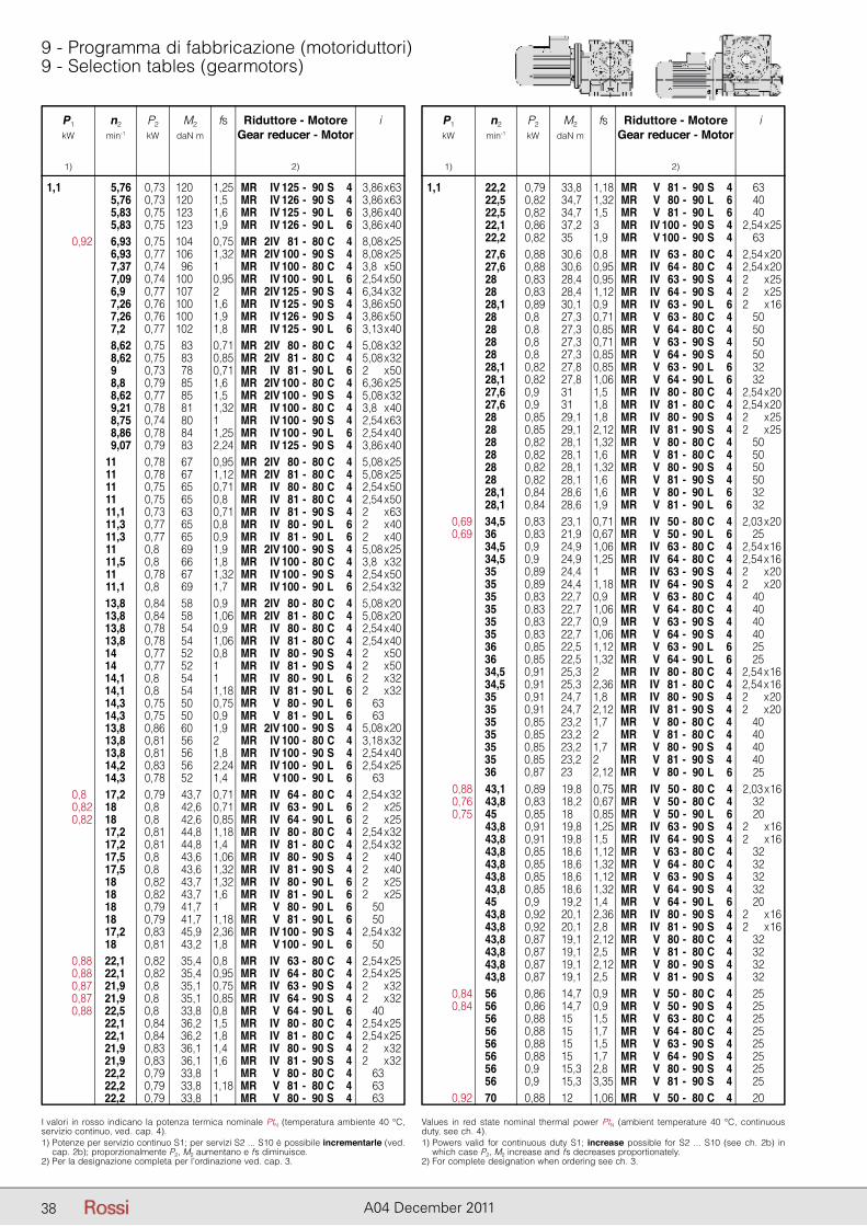
P1 n2 P2 M2 fs Riduttore - Motore i kW min-1 kW daN m Gear reducer - Motor
1) 2)
P1 n2 P2 M2 fs Riduttore - Motore i kW min-1 kW daN m Gear reducer - Motor
1) 2)
38 A04 December 2011
9 - Programma di fabbricazione (motoriduttori)9 - Selection tables (gearmotors)
P1 n2 P2 M2 fs Riduttore - Motore i kW min-1 kW daN m Gear reducer - Motor
1) 2)
I valori in rosso indicano la potenza termica nominale PtN (temperatura ambiente 40 °C, servizio continuo, ved. cap. 4).1) Potenze per servizio continuo S1; per servizi S2 ... S10 è possibile incrementarle (ved.
cap. 2b); proporzionalmente P2, M2 aumentano e fs diminuisce.2) Per la designazione completa per l’ordinazione ved. cap. 3.
Values in red state nominal thermal power PtN (ambient temperature 40 °C, continuous duty, see ch. 4).1) Powers valid for continuous duty S1; increase possible for S2 ... S10 (see ch. 2b) in
which case P2, M2 increase and fs decreases proportionately.2) For complete designation when ordering see ch. 3.
1,1 5,76 0,73 120 1,25 MR IV 125 - 90 S 4 23,86 x 63 5,76 0,73 120 1,5 MR IV 126 - 90 S 4 23,86 x 63 5,83 0,75 123 1,6 MR IV 125 - 90 L 6 23,86 x 40 5,83 0,75 123 1,9 MR IV 126 - 90 L 6 23,86 x 40 0,92 6,93 0,75 104 0,75 MR 2IV 81 - 80 C 4 28,08 x 25 6,93 0,77 106 1,32 MR 2IV 100 - 90 S 4 28,08 x 25 7,37 0,74 96 1 MR IV 100 - 80 C 4 23,8 x 50 7,09 0,74 100 0,95 MR IV 100 - 90 L 6 22,54 x 50 6,9 0,77 107 2 MR 2IV 125 - 90 S 4 26,34 x 32 7,26 0,76 100 1,6 MR IV 125 - 90 S 4 23,86 x 50 7,26 0,76 100 1,9 MR IV 126 - 90 S 4 23,86 x 50 7,2 0,77 102 1,8 MR IV 125 - 90 L 6 23,13 x 40 8,62 0,75 83 0,71 MR 2IV 80 - 80 C 4 25,08 x 32 8,62 0,75 83 0,85 MR 2IV 81 - 80 C 4 25,08 x 32 9 0,73 78 0,71 MR IV 81 - 90 L 6 22 x 50 8,8 0,79 85 1,6 MR 2IV 100 - 80 C 4 26,36 x 25 8,62 0,77 85 1,5 MR 2IV 100 - 90 S 4 25,08 x 32 9,21 0,78 81 1,32 MR IV 100 - 80 C 4 23,8 x 40 8,75 0,74 80 1 MR IV 100 - 90 S 4 22,54 x 63 8,86 0,78 84 1,25 MR IV 100 - 90 L 6 22,54 x 40 9,07 0,79 83 2,24 MR IV 125 - 90 S 4 23,86 x 40 11 0,78 67 0,95 MR 2IV 80 - 80 C 4 25,08 x 25 11 0,78 67 1,12 MR 2IV 81 - 80 C 4 25,08 x 25 11 0,75 65 0,71 MR IV 80 - 80 C 4 22,54 x 50 11 0,75 65 0,8 MR IV 81 - 80 C 4 22,54 x 50 11,1 0,73 63 0,71 MR IV 81 - 90 S 4 22 x 63 11,3 0,77 65 0,8 MR IV 80 - 90 L 6 22 x 40 11,3 0,77 65 0,9 MR IV 81 - 90 L 6 22 x 40 11 0,8 69 1,9 MR 2IV 100 - 90 S 4 25,08 x 25 11,5 0,8 66 1,8 MR IV 100 - 80 C 4 23,8 x 32 11 0,78 67 1,32 MR IV 100 - 90 S 4 22,54 x 50 11,1 0,8 69 1,7 MR IV 100 - 90 L 6 22,54 x 32 13,8 0,84 58 0,9 MR 2IV 80 - 80 C 4 25,08 x 20 13,8 0,84 58 1,06 MR 2IV 81 - 80 C 4 25,08 x 20 13,8 0,78 54 0,9 MR IV 80 - 80 C 4 22,54 x 40 13,8 0,78 54 1,06 MR IV 81 - 80 C 4 22,54 x 40 14 0,77 52 0,8 MR IV 80 - 90 S 4 22 x 50 14 0,77 52 1 MR IV 81 - 90 S 4 22 x 50 14,1 0,8 54 1 MR IV 80 - 90 L 6 22 x 32 14,1 0,8 54 1,18 MR IV 81 - 90 L 6 22 x 32 14,3 0,75 50 0,75 MR V 80 - 90 L 6 63 14,3 0,75 50 0,9 MR V 81 - 90 L 6 63 13,8 0,86 60 1,9 MR 2IV 100 - 90 S 4 25,08 x 20 13,8 0,81 56 2 MR IV 100 - 80 C 4 23,18 x 32 13,8 0,81 56 1,8 MR IV 100 - 90 S 4 22,54 x 40 14,2 0,83 56 2,24 MR IV 100 - 90 L 6 22,54 x 25 14,3 0,78 52 1,4 MR V 100 - 90 L 6 63 0,8 17,2 0,79 43,7 0,71 MR IV 64 - 80 C 4 22,54 x 32 0,82 18 0,8 42,6 0,71 MR IV 63 - 90 L 6 22 x 25 0,82 18 0,8 42,6 0,85 MR IV 64 - 90 L 6 22 x 25 17,2 0,81 44,8 1,18 MR IV 80 - 80 C 4 22,54 x 32 17,2 0,81 44,8 1,4 MR IV 81 - 80 C 4 22,54 x 32 17,5 0,8 43,6 1,06 MR IV 80 - 90 S 4 22 x 40 17,5 0,8 43,6 1,32 MR IV 81 - 90 S 4 22 x 40 18 0,82 43,7 1,32 MR IV 80 - 90 L 6 22 x 25 18 0,82 43,7 1,6 MR IV 81 - 90 L 6 22 x 25 18 0,79 41,7 1 MR V 80 - 90 L 6 50 18 0,79 41,7 1,18 MR V 81 - 90 L 6 50 17,2 0,83 45,9 2,36 MR IV 100 - 90 S 4 22,54 x 32 18 0,81 43,2 1,8 MR V 100 - 90 L 6 50 0,88 22,1 0,82 35,4 0,8 MR IV 63 - 80 C 4 22,54 x 25 0,88 22,1 0,82 35,4 0,95 MR IV 64 - 80 C 4 22,54 x 25 0,87 21,9 0,8 35,1 0,75 MR IV 63 - 90 S 4 22 x 32 0,87 21,9 0,8 35,1 0,85 MR IV 64 - 90 S 4 22 x 32 0,88 22,5 0,8 33,8 0,8 MR V 64 - 90 L 6 40 22,1 0,84 36,2 1,5 MR IV 80 - 80 C 4 22,54 x 25 22,1 0,84 36,2 1,8 MR IV 81 - 80 C 4 22,54 x 25 21,9 0,83 36,1 1,4 MR IV 80 - 90 S 4 22 x 32 21,9 0,83 36,1 1,6 MR IV 81 - 90 S 4 22 x 32 22,2 0,79 33,8 1 MR V 80 - 80 C 4 63 22,2 0,79 33,8 1,18 MR V 81 - 80 C 4 63 22,2 0,79 33,8 1 MR V 80 - 90 S 4 63
P1 n2 P2 M2 fs Riduttore - Motore i kW min-1 kW daN m Gear reducer - Motor
1) 2)
1,1 22,2 0,79 33,8 1,18 MR V 81 - 90 S 4 63 22,5 0,82 34,7 1,32 MR V 80 - 90 L 6 40 22,5 0,82 34,7 1,5 MR V 81 - 90 L 6 40 22,1 0,86 37,2 3 MR IV 100 - 90 S 4 22,54 x 25 22,2 0,82 35 1,9 MR V 100 - 90 S 4 63 27,6 0,88 30,6 0,8 MR IV 63 - 80 C 4 22,54 x 20 27,6 0,88 30,6 0,95 MR IV 64 - 80 C 4 22,54 x 20 28 0,83 28,4 0,95 MR IV 63 - 90 S 4 22 x 25 28 0,83 28,4 1,12 MR IV 64 - 90 S 4 22 x 25 28,1 0,89 30,1 0,9 MR IV 63 - 90 L 6 22 x 16 28 0,8 27,3 0,71 MR V 63 - 80 C 4 50 28 0,8 27,3 0,85 MR V 64 - 80 C 4 50 28 0,8 27,3 0,71 MR V 63 - 90 S 4 50 28 0,8 27,3 0,85 MR V 64 - 90 S 4 50 28,1 0,82 27,8 0,85 MR V 63 - 90 L 6 32 28,1 0,82 27,8 1,06 MR V 64 - 90 L 6 32 27,6 0,9 31 1,5 MR IV 80 - 80 C 4 22,54 x 20 27,6 0,9 31 1,8 MR IV 81 - 80 C 4 22,54 x 20 28 0,85 29,1 1,8 MR IV 80 - 90 S 4 22 x 25 28 0,85 29,1 2,12 MR IV 81 - 90 S 4 22 x 25 28 0,82 28,1 1,32 MR V 80 - 80 C 4 50 28 0,82 28,1 1,6 MR V 81 - 80 C 4 50 28 0,82 28,1 1,32 MR V 80 - 90 S 4 50 28 0,82 28,1 1,6 MR V 81 - 90 S 4 50 28,1 0,84 28,6 1,6 MR V 80 - 90 L 6 32 28,1 0,84 28,6 1,9 MR V 81 - 90 L 6 32 0,69 34,5 0,83 23,1 0,71 MR IV 50 - 80 C 4 22,03 x 20 0,69 36 0,83 21,9 0,67 MR V 50 - 90 L 6 25 34,5 0,9 24,9 1,06 MR IV 63 - 80 C 4 22,54 x 16 34,5 0,9 24,9 1,25 MR IV 64 - 80 C 4 22,54 x 16 35 0,89 24,4 1 MR IV 63 - 90 S 4 22 x 20 35 0,89 24,4 1,18 MR IV 64 - 90 S 4 22 x 20 35 0,83 22,7 0,9 MR V 63 - 80 C 4 40 35 0,83 22,7 1,06 MR V 64 - 80 C 4 40 35 0,83 22,7 0,9 MR V 63 - 90 S 4 40 35 0,83 22,7 1,06 MR V 64 - 90 S 4 40 36 0,85 22,5 1,12 MR V 63 - 90 L 6 25 36 0,85 22,5 1,32 MR V 64 - 90 L 6 25 34,5 0,91 25,3 2 MR IV 80 - 80 C 4 22,54 x 16 34,5 0,91 25,3 2,36 MR IV 81 - 80 C 4 22,54 x 16 35 0,91 24,7 1,8 MR IV 80 - 90 S 4 22 x 20 35 0,91 24,7 2,12 MR IV 81 - 90 S 4 22 x 20 35 0,85 23,2 1,7 MR V 80 - 80 C 4 40 35 0,85 23,2 2 MR V 81 - 80 C 4 40 35 0,85 23,2 1,7 MR V 80 - 90 S 4 40 35 0,85 23,2 2 MR V 81 - 90 S 4 40 36 0,87 23 2,12 MR V 80 - 90 L 6 25 0,88 43,1 0,89 19,8 0,75 MR IV 50 - 80 C 4 22,03 x 16 0,76 43,8 0,83 18,2 0,67 MR V 50 - 80 C 4 32 0,75 45 0,85 18 0,85 MR V 50 - 90 L 6 20 43,8 0,91 19,8 1,25 MR IV 63 - 90 S 4 22 x 16 43,8 0,91 19,8 1,5 MR IV 64 - 90 S 4 22 x 16 43,8 0,85 18,6 1,12 MR V 63 - 80 C 4 32 43,8 0,85 18,6 1,32 MR V 64 - 80 C 4 32 43,8 0,85 18,6 1,12 MR V 63 - 90 S 4 32 43,8 0,85 18,6 1,32 MR V 64 - 90 S 4 32 45 0,9 19,2 1,4 MR V 64 - 90 L 6 20 43,8 0,92 20,1 2,36 MR IV 80 - 90 S 4 22 x 16 43,8 0,92 20,1 2,8 MR IV 81 - 90 S 4 22 x 16 43,8 0,87 19,1 2,12 MR V 80 - 80 C 4 32 43,8 0,87 19,1 2,5 MR V 81 - 80 C 4 32 43,8 0,87 19,1 2,12 MR V 80 - 90 S 4 32 43,8 0,87 19,1 2,5 MR V 81 - 90 S 4 32 0,84 56 0,86 14,7 0,9 MR V 50 - 80 C 4 25 0,84 56 0,86 14,7 0,9 MR V 50 - 90 S 4 25 56 0,88 15 1,5 MR V 63 - 80 C 4 25 56 0,88 15 1,7 MR V 64 - 80 C 4 25 56 0,88 15 1,5 MR V 63 - 90 S 4 25 56 0,88 15 1,7 MR V 64 - 90 S 4 25 56 0,9 15,3 2,8 MR V 80 - 90 S 4 25 56 0,9 15,3 3,35 MR V 81 - 90 S 4 25 0,92 70 0,88 12 1,06 MR V 50 - 80 C 4 20
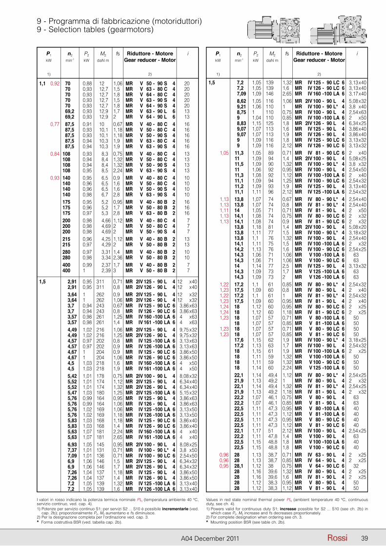
P1 n2 P2 M2 fs Riduttore - Motore i kW min-1 kW daN m Gear reducer - Motor
1) 2)
P1 n2 P2 M2 fs Riduttore - Motore i kW min-1 kW daN m Gear reducer - Motor
1) 2)
39A04 December 2011
9 - Programma di fabbricazione (motoriduttori)9 - Selection tables (gearmotors)
P1 n2 P2 M2 fs Riduttore - Motore i kW min-1 kW daN m Gear reducer - Motor
1) 2)
I valori in rosso indicano la potenza termica nominale PtN (temperatura ambiente 40 °C, servizio continuo, ved. cap. 4).1) Potenze per servizio continuo S1; per servizi S2 ... S10 è possibile incrementarle (ved.
cap. 2b); proporzionalmente P2, M2 aumentano e fs diminuisce.2) Per la designazione completa per l’ordinazione ved. cap. 3.* Forma costruttiva B5R (ved. tabella cap. 2b).
Values in red state nominal thermal power PtN (ambient temperature 40 °C, continuous duty, see ch. 4).1) Powers valid for continuous duty S1; increase possible for S2 ... S10 (see ch. 2b) in
which case P2, M2 increase and fs decreases proportionately.2) For complete designation when ordering see ch. 3.* Mounting position B5R (see table ch. 2b).
1,1 0,92 70 0,88 12 1,06 MR V 50 - 90 S 4 20 70 0,93 12,7 1,5 MR V 63 - 80 C 4 20 70 0,93 12,7 1,8 MR V 64 - 80 C 4 20 70 0,93 12,7 1,5 MR V 63 - 90 S 4 20 70 0,93 12,7 1,8 MR V 64 - 90 S 4 20 69,2 0,93 12,9 1,7 MR V 63 - 90 L 6 13 69,2 0,93 12,9 2 MR V 64 - 90 L 6 13 0,77 87,5 0,91 10 0,67 MR V 40 - 80 C 4 16 87,5 0,93 10,1 1,18 MR V 50 - 80 C 4 16 87,5 0,93 10,1 1,18 MR V 50 - 90 S 4 16 87,5 0,94 10,3 1,9 MR V 63 - 80 C 4 16 87,5 0,94 10,3 1,9 MR V 63 - 90 S 4 16 0,84 108 0,93 8,3 0,75 MR V 40 - 80 C 4 13 108 0,94 8,4 1,32 MR V 50 - 80 C 4 13 108 0,94 8,4 1,32 MR V 50 - 90 S 4 13 108 0,95 8,5 2,24 MR V 63 - 90 S 4 13 0,93 140 0,95 6,5 0,9 MR V 40 - 80 C 4 10 140 0,96 6,5 1,6 MR V 50 - 80 C 4 10 140 0,96 6,5 1,6 MR V 50 - 90 S 4 10 140 0,98 6,7 2,8 MR V 63 - 90 S 4 10 175 0,95 5,2 0,95 MR V 40 - 80 B 2 16 175 0,96 5,2 1,7 MR V 50 - 80 B 2 16 175 0,97 5,3 2,8 MR V 63 - 80 B 2 16 200 0,98 4,66 1,12 MR V 40 - 80 C 4 7 200 0,98 4,69 2 MR V 50 - 80 C 4 7 200 0,98 4,69 2 MR V 50 - 90 S 4 7 215 0,96 4,25 1,12 MR V 40 - 80 B 2 13 215 0,97 4,29 2 MR V 50 - 80 B 2 13 280 0,97 3,31 1,4 MR V 40 - 80 B 2 10 280 0,98 3,34 2,36 MR V 50 - 80 B 2 10 400 0,99 2,37 1,7 MR V 40 - 80 B 2 7 400 1 2,39 3 MR V 50 - 80 B 2 7
1,5 2,91 0,95 311 0,71 MR 2IV 125 - 90 L 4 12 x 40 2,91 0,95 311 0,8 MR 2IV 126 - 90 L 4 12 x 40 3,64 1 262 0,9 MR 2IV 125 - 90 L 4 12 x 32 3,64 1 262 1,06 MR 2IV 126 - 90 L 4 12 x 32 3,7 0,94 243 0,67 MR IV 125 - 90 LC 6 23,86 x 63 3,7 0,94 243 0,8 MR IV 126 - 90 LC 6 23,86 x 63 3,57 0,98 261 1,25 MR IV 160 - 100 LA 6 24 x 63 3,57 0,98 261 1,4 MR IV 161 - 100 LA 6 24 x 63 4,49 1,02 216 1,06 MR 2IV 125 - 90 L 4 29,75 x 32 4,49 1,02 216 1,25 MR 2IV 126 - 90 L 4 29,75 x 32 4,57 0,97 202 0,8 MR IV 125 - 100 LA 6 23,13 x 63 4,57 0,97 202 0,9 MR IV 126 - 100 LA 6 23,13 x 63 4,67 1 204 0,9 MR IV 125 - 90 LC 6 23,86 x 50 4,67 1 204 1,06 MR IV 126 - 90 LC 6 23,86 x 50 4,5 1,03 218 1,6 MR IV 160 - 100 LA 6 24 x 50 4,5 1,03 218 1,9 MR IV 161 - 100 LA 6 24 x 50 5,42 1,01 178 0,75 MR 2IV 100 - 90 L 4 28,08 x 32 5,52 1,01 174 1,12 MR 2IV 125 - 90 L 4 26,34 x 40 5,52 1,01 174 1,32 MR 2IV 126 - 90 L 4 26,34 x 40 5,47 1,03 180 1,25 MR 2IV 125 - 100 LA 6 25,15 x 32 5,76 0,99 164 0,95 MR IV 125 - 90 L 4 23,86 x 63 5,76 0,99 164 1,06 MR IV 126 - 90 L 4 23,86 x 63 5,76 1,02 169 1,06 MR IV 125 - 100 LA 6 23,13 x 50 5,76 1,02 169 1,18 MR IV 126 - 100 LA 6 23,13 x 50 5,83 1,03 168 1,18 MR IV 125 - 90 LC 6 23,86 x 40 5,83 1,03 168 1,4 MR IV 126 - 90 LC 6 23,86 x 40 5,63 1,07 181 2,24 MR IV 160 - 100 LA 6 24 x 40 5,63 1,07 181 2,65 MR IV 161 - 100 LA 6 24 x 40 6,93 1,05 145 0,95 MR 2IV 100 - 90 L 4 28,08 x 25 7,37 1,01 131 0,71 MR IV 100 - 90 L* 4 23,8 x 50 7,09 1,01 136 0,71 MR IV 100 - 90 LC 6 22,54 x 50 6,9 1,06 146 1,5 MR 2IV 125 - 90 L 4 26,34 x 32 6,9 1,06 146 1,7 MR 2IV 126 - 90 L 4 26,34 x 32 7,26 1,04 137 1,18 MR IV 125 - 90 L 4 23,86 x 50 7,26 1,04 137 1,4 MR IV 126 - 90 L 4 23,86 x 50 7,2 1,05 139 1,32 MR IV 125 - 100 LA 6 23,13 x 40 7,2 1,05 139 1,6 MR IV 126 - 100 LA 6 23,13 x 40
P1 n2 P2 M2 fs Riduttore - Motore i kW min-1 kW daN m Gear reducer - Motor
1) 2) 1,5 7,2 1,05 139 1,32 MR IV 125 - 90 LC 6 23,13 x 40 7,2 1,05 139 1,6 MR IV 126 - 90 LC 6 23,13 x 40 7,09 1,09 146 2,65 MR IV 160 - 100 LA 6 23,17 x 40 8,62 1,05 116 1,06 MR 2IV 100 - 90 L 4 25,08 x 32 9,21 1,06 110 1 MR IV 100 - 90 L* 4 23,8 x 40 8,75 1 110 0,75 MR IV 100 - 90 L 4 22,54 x 63 9 1,04 110 0,85 MR IV 100 - 100 LA 6 22 x 50 8,83 1,15 125 1,8 MR 2IV 126 - 90 L 4 26,34 x 25 9,07 1,07 113 1,6 MR IV 125 - 90 L 4 23,86 x 40 9,07 1,07 113 1,9 MR IV 126 - 90 L 4 23,86 x 40 9 1,09 116 1,8 MR IV 125 - 90 LC 6 23,13 x 32 9 1,09 116 2,12 MR IV 126 - 90 LC 6 23,13 x 32 1,05 11,3 1,05 89 0,71 MR IV 81 - 90 LC 6 22 x 40 11 1,09 94 1,4 MR 2IV 100 - 90 L 4 25,08 x 25 11,5 1,09 90 1,32 MR IV 100 - 90 L* 4 23,8 x 32 11 1,06 92 0,95 MR IV 100 - 90 L 4 22,54 x 50 11,3 1,08 92 1,12 MR IV 100 - 100 LA 6 22 x 40 11,1 1,09 94 1,25 MR IV 100 - 90 LC 6 22,54 x 32 11,2 1,09 93 1,9 MR IV 125 - 90 L 4 23,13 x 40 11,1 1,11 96 2,12 MR IV 125 - 100 LA 6 22,54 x 32 1,13 13,8 1,07 74 0,67 MR IV 80 - 90 L* 4 22,54 x 40 1,13 13,8 1,07 74 0,8 MR IV 81 - 90 L* 4 22,54 x 40 1,11 14 1,05 71 0,71 MR IV 81 - 90 L 4 22 x 50 1,13 14,1 1,08 74 0,75 MR IV 80 - 90 LC 6 22 x 32 1,13 14,1 1,08 74 0,9 MR IV 81 - 90 LC 6 22 x 32 13,8 1,18 81 1,4 MR 2IV 100 - 90 L 4 25,08 x 20 13,8 1,11 77 1,5 MR IV 100 - 90 L* 4 23,18 x 32 13,8 1,1 76 1,32 MR IV 100 - 90 L 4 22,54 x 40 14,1 1,11 75 1,5 MR IV 100 - 100 LA 6 22 x 32 14,2 1,13 76 1,6 MR IV 100 - 90 LC 6 22,54 x 25 14,3 1,06 71 1,06 MR V 100 - 100 LA 6 63 14,3 1,06 71 1,06 MR V 100 - 90 LC 6 63 14 1,14 77 2,5 MR IV 125 - 90 L 4 23,13 x 32 14,3 1,09 73 1,7 MR V 125 - 100 LA 6 63 14,3 1,09 73 2 MR V 126 - 100 LA 6 63 1,22 17,2 1,1 61 0,85 MR IV 80 - 90 L* 4 22,54 x 32 1,23 17,5 1,09 60 0,8 MR IV 80 - 90 L 4 22 x 40 1,22 17,2 1,1 61 1 MR IV 81 - 90 L* 4 22,54 x 32 1,23 17,5 1,09 60 0,95 MR IV 81 - 90 L 4 22 x 40 1,24 18 1,12 60 0,95 MR IV 80 - 90 LC 6 22 x 25 1,24 18 1,12 60 1,18 MR IV 81 - 90 LC 6 22 x 25 1,23 18 1,07 57 0,71 MR V 80 - 100 LA 6 50 18 1,07 57 0,85 MR V 81 - 100 LA 6 50 1,23 18 1,07 57 0,71 MR V 80 - 90 LC 6 50 1,23 18 1,07 57 0,85 MR V 81 - 90 LC 6 50 17,6 1,15 62 1,9 MR IV 100 - 90 L* 4 23,18 x 25 17,2 1,13 63 1,7 MR IV 100 - 90 L 4 22,54 x 32 18 1,15 61 1,9 MR IV 100 - 100 LA 6 22 x 25 18 1,11 59 1,32 MR V 100 - 100 LA 6 50 18 1,11 59 1,32 MR V 100 - 90 LC 6 50 18 1,14 60 2,24 MR V 125 - 100 LA 6 50 22,1 1,14 49,4 1,12 MR IV 80 - 90 L* 4 22,54 x 25 21,9 1,13 49,2 1 MR IV 80 - 90 L 4 22 x 32 22,1 1,14 49,4 1,32 MR IV 81 - 90 L* 4 22,54 x 25 21,9 1,13 49,2 1,18 MR IV 81 - 90 L 4 22 x 32 22,2 1,07 46,1 0,75 MR V 80 - 90 L 4 63 22,2 1,07 46,1 0,85 MR V 81 - 90 L 4 63 22,5 1,11 47,3 0,95 MR V 80 - 100 LA 6 40 22,5 1,11 47,3 1,12 MR V 81 - 100 LA 6 40 22,5 1,11 47,3 0,95 MR V 80 - 90 LC 6 40 22,5 1,11 47,3 1,12 MR V 81 - 90 LC 6 40 22,1 1,17 51 2,12 MR IV 100 - 90 L 4 22,54 x 25 22,2 1,11 47,8 1,4 MR V 100 - 90 L 4 63 22,5 1,15 48,8 1,8 MR V 100 - 100 LA 6 40 22,5 1,15 48,8 1,8 MR V 100 - 90 LC 6 40 0,96 28 1,13 38,7 0,71 MR IV 63 - 90 L 4 22 x 25 0,96 28 1,13 38,7 0,85 MR IV 64 - 90 L 4 22 x 25 0,95 28,1 1,12 38 0,75 MR V 64 - 90 LC 6 32 28 1,16 39,6 1,32 MR IV 80 - 90 L 4 22 x 25 28 1,16 39,6 1,6 MR IV 81 - 90 L 4 22 x 25 28 1,12 38,3 0,95 MR V 80 - 90 L 4 50 28 1,12 38,3 1,12 MR V 81 - 90 L 4 50
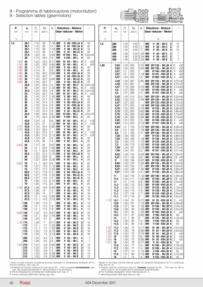
P1 n2 P2 M2 fs Riduttore - Motore i kW min-1 kW daN m Gear reducer - Motor
1) 2)
P1 n2 P2 M2 fs Riduttore - Motore i kW min-1 kW daN m Gear reducer - Motor
1) 2)
40 A04 December 2011
9 - Programma di fabbricazione (motoriduttori)9 - Selection tables (gearmotors)
P1 n2 P2 M2 fs Riduttore - Motore i kW min-1 kW daN m Gear reducer - Motor
1) 2)
I valori in rosso indicano la potenza termica nominale PtN (temperatura ambiente 40 °C, servizio continuo, ved. cap. 4).1) Potenze per servizio continuo S1; per servizi S2 ... S10 è possibile incrementarle (ved.
cap. 2b); proporzionalmente P2, M2 aumentano e fs diminuisce.2) Per la designazione completa per l’ordinazione ved. cap. 3.* Forma costruttiva B5R (ved. tabella cap. 2b).
Values in red state nominal thermal power PtN (ambient temperature 40 °C, continuous duty, see ch. 4).1) Powers valid for continuous duty S1; increase possible for S2 ... S10 (see ch. 2b) in
which case P2, M2 increase and fs decreases proportionately.2) For complete designation when ordering see ch. 3.* Mounting position B5R (see table ch. 2b).
P1 n2 P2 M2 fs Riduttore - Motore i kW min-1 kW daN m Gear reducer - Motor
1) 2)
1,5 280 1,32 4,52 1 MR V 40 - 80 C 2 10 280 1,33 4,55 1,7 MR V 50 - 80 C 2 10 280 1,33 4,55 1,7 MR V 50 - 90 S 2 10 400 1,36 3,24 1,25 MR V 40 - 80 C 2 7 400 1,36 3,25 2,24 MR V 50 - 80 C 2 7 400 1,36 3,25 2,24 MR V 50 - 90 S 2 7
1,85 3,64 1,23 323 0,75 MR 2IV 125 - 90 LB 4 12 x 32 3,64 1,23 323 0,85 MR 2IV 126 - 90 LB 4 12 x 32 3,57 1,2 322 1 MR IV 160 - 100 LB 6 24 x 63 3,57 1,2 322 1,18 MR IV 161 - 100 LB 6 24 x 63 3,57 1,24 332 1,8 MR IV 200 - 100 LB 6 24 x 63 4,49 1,25 267 0,85 MR 2IV 125 - 90 LB 4 29,75 x 32 4,49 1,25 267 1 MR 2IV 126 - 90 LB 4 29,75 x 32 4,57 1,19 250 0,75 MR IV 126 - 100 LB 6 23,13 x 63 4,5 1,27 269 1,32 MR IV 160 - 100 LB 6 24 x 50 4,5 1,27 269 1,5 MR IV 161 - 100 LB 6 24 x 50 5,52 1,24 215 0,9 MR 2IV 125 - 90 LB 4 26,34 x 40 5,52 1,24 215 1,06 MR 2IV 126 - 90 LB 4 26,34 x 40 5,47 1,27 222 1 MR 2IV 125 - 100 LB 6 25,15 x 32 5,47 1,27 222 1,18 MR 2IV 126 - 100 LB 6 25,15 x 32 5,76 1,22 203 0,75 MR IV 125 - 90 LB 4 23,86 x 63 5,76 1,22 203 0,85 MR IV 126 - 90 LB 4 23,86 x 63 5,76 1,26 209 0,85 MR IV 125 - 100 LB 6 23,13 x 50 5,76 1,26 209 0,95 MR IV 126 - 100 LB 6 23,13 x 50 5,63 1,31 223 1,8 MR IV 160 - 100 LB 6 24 x 40 5,63 1,31 223 2,12 MR IV 161 - 100 LB 6 24 x 40 6,93 1,3 179 0,75 MR 2IV 100 - 90 LB 4 28,08 x 25 6,9 1,3 180 1,18 MR 2IV 125 - 90 LB 4 26,34 x 32 6,9 1,3 180 1,4 MR 2IV 126 - 90 LB 4 26,34 x 32 7,26 1,28 169 1 MR IV 125 - 90 LB 4 23,86 x 50 7,26 1,28 169 1,18 MR IV 126 - 90 LB 4 23,86 x 50 7,2 1,29 172 1,12 MR IV 125 - 100 LB 6 23,13 x 40 7,2 1,29 172 1,32 MR IV 126 - 100 LB 6 23,13 x 40 7,09 1,34 181 2,12 MR IV 160 - 100 LB 6 23,17 x 40 7,09 1,34 181 2,5 MR IV 161 - 100 LB 6 23,17 x 40 8,62 1,29 143 0,85 MR 2IV 100 - 90 LB 4 25,08 x 32 9,21 1,31 135 0,8 MR IV 100 - 90 LB* 4 23,8 x 40 9 1,28 136 0,67 MR IV 100 - 100 LB 6 22 x 50 8,83 1,42 154 1,25 MR 2IV 125 - 90 LB 4 26,34 x 25 8,83 1,42 154 1,5 MR 2IV 126 - 90 LB 4 26,34 x 25 9,07 1,32 139 1,32 MR IV 125 - 90 LB 4 23,86 x 40 9,07 1,32 139 1,6 MR IV 126 - 90 LB 4 23,86 x 40 11 1,34 116 1,12 MR 2IV 100 - 90 LB 4 25,08 x 25 11,5 1,34 111 1,06 MR IV 100 - 90 LB* 4 23,8 x 32 11 1,3 113 0,8 MR IV 100 - 90 LB 4 22,54 x 50 11,3 1,33 113 0,9 MR IV 100 - 100 LB 6 22 x 40 11,2 1,35 115 1,5 MR IV 125 - 90 LB 4 23,13 x 40 11,2 1,35 115 1,8 MR IV 126 - 90 LB 4 23,13 x 40 11,1 1,37 118 1,7 MR IV 125 - 100 LB 6 22,54 x 32 11,1 1,37 118 2 MR IV 126 - 100 LB 6 22,54 x 32 1,13 14,1 1,34 91 0,71 MR IV 81 - 100 LB 6 22 x 32 13,8 1,45 101 1,12 MR 2IV 100 - 90 LB 4 25,08 x 20 13,8 1,37 95 1,18 MR IV 100 - 90 LB* 4 23,18 x 32 13,8 1,36 94 1,06 MR IV 100 - 90 LB 4 22,54 x 40 14,1 1,37 93 1,25 MR IV 100 - 100 LB 6 22 x 32 14,3 1,31 87 0,85 MR V 100 - 100 LB 6 63 14 1,4 96 2 MR IV 125 - 90 LB 4 23,13 x 32 14,3 1,35 90 1,4 MR V 125 - 100 LB 6 63 14,3 1,35 90 1,6 MR V 126 - 100 LB 6 63 1,22 17,2 1,36 75 0,71 MR IV 80 - 90 LB* 4 22,54 x 32 1,22 17,2 1,36 75 0,85 MR IV 81 - 90 LB* 4 22,54 x 32 1,23 17,5 1,35 73 0,75 MR IV 81 - 90 LB 4 22 x 40 1,24 18 1,38 73 0,8 MR IV 80 - 100 LB 6 22 x 25 1,24 18 1,38 73 0,95 MR IV 81 - 100 LB 6 22 x 25 1,37 18 1,32 70 0,71 MR V 81 - 100 LB 6 50 17,6 1,42 77 1,5 MR IV 100 - 90 LB* 4 23,18 x 25 17,2 1,39 77 1,4 MR IV 100 - 90 LB 4 22,54 x 32 18 1,37 73 1,12 MR V 100 - 100 LB 6 50 17,9 1,51 80 2,12 MR IV 125 - 90 LB 4 23,13 x 25 18 1,4 74 1,8 MR V 125 - 100 LB 6 50
1,5 28,1 1,15 39 1,18 MR V 80 - 100 LA 6 32 28,1 1,15 39 1,4 MR V 81 - 100 LA 6 32 28,1 1,15 39 1,18 MR V 80 - 90 LC 6 32 28,1 1,15 39 1,4 MR V 81 - 90 LC 6 32 27,6 1,24 43 2,36 MR IV 100 - 90 L 4 22,54 x 20 28 1,15 39,4 1,8 MR V 100 - 90 L 4 50 1,24 35 1,22 33,2 0,71 MR IV 63 - 90 L 4 22 x 20 1,24 35 1,22 33,2 0,85 MR IV 64 - 90 L 4 22 x 20 1,08 35 1,14 31 0,67 MR V 63 - 90 L 4 40 1,08 35 1,14 31 0,8 MR V 64 - 90 L 4 40 1,06 36 1,16 30,7 0,85 MR V 63 - 100 LA 6 25 1,06 36 1,16 30,7 1 MR V 64 - 100 LA 6 25 1,06 36 1,16 30,7 0,85 MR V 63 - 90 LC 6 25 1,06 36 1,16 30,7 1 MR V 64 - 90 LC 6 25 34,5 1,24 34,5 1,5 MR IV 80 - 90 L* 4 22,54 x 16 35 1,24 33,7 1,32 MR IV 80 - 90 L 4 22 x 20 34,5 1,24 34,5 1,8 MR IV 81 - 90 L* 4 22,54 x 16 35 1,24 33,7 1,6 MR IV 81 - 90 L 4 22 x 20 35 1,16 31,7 1,25 MR V 80 - 90 L 4 40 35 1,16 31,7 1,5 MR V 81 - 90 L 4 40 36 1,18 31,4 1,6 MR V 80 - 100 LA 6 25 36 1,18 31,4 1,9 MR V 81 - 100 LA 6 25 36 1,18 31,4 1,6 MR V 80 - 90 LC 6 25 36 1,18 31,4 1,9 MR V 81 - 90 LC 6 25 34,5 1,26 34,9 2,8 MR IV 100 - 90 L 4 22,54 x 16 35 1,19 32,4 2,36 MR V 100 - 90 L 4 40 43,8 1,24 27 0,9 MR IV 63 - 90 L 4 22 x 16 43,8 1,24 27 1,12 MR IV 64 - 90 L 4 22 x 16 1,17 43,8 1,16 25,4 0,85 MR V 63 - 90 L 4 32 1,17 43,8 1,16 25,4 1 MR V 64 - 90 L 4 32 43,8 1,26 27,5 1,7 MR IV 80 - 90 L 4 22 x 16 43,8 1,26 27,5 2,12 MR IV 81 - 90 L 4 22 x 16 43,8 1,19 26 1,6 MR V 80 - 90 L 4 32 43,8 1,19 26 1,9 MR V 81 - 90 L 4 32 0,84 56 1,17 20 0,67 MR V 50 - 90 L 4 25 56 1,2 20,4 1,06 MR V 63 - 90 L 4 25 56 1,2 20,4 1,25 MR V 64 - 90 L 4 25 56,3 1,25 21,3 1,12 MR V 63 - 100 LA 6 16 56 1,22 20,8 2 MR V 80 - 90 L 4 25 56 1,22 20,8 2,36 MR V 81 - 90 L 4 25 0,92 70 1,2 16,3 0,8 MR V 50 - 90 L 4 20 70 1,27 17,3 1,12 MR V 63 - 90 L 4 20 70 1,27 17,3 1,32 MR V 64 - 90 L 4 20 69,2 1,27 17,6 1,5 MR V 64 - 100 LA 6 13 69,2 1,27 17,6 1,25 MR V 63 - 90 LC 6 13 69,2 1,27 17,6 1,5 MR V 64 - 90 LC 6 13 70 1,28 17,5 2,12 MR V 80 - 90 L 4 20 70 1,28 17,5 2,5 MR V 81 - 90 L 4 20 1,18 87,5 1,26 13,8 0,85 MR V 50 - 90 L 4 16 87,5 1,28 14 1,4 MR V 63 - 90 L 4 16 87,5 1,28 14 1,7 MR V 64 - 90 L 4 16 87,5 1,3 14,2 2,65 MR V 80 - 90 L 4 16 87,5 1,3 14,2 3,15 MR V 81 - 90 L 4 16 108 1,29 11,4 1 MR V 50 - 90 L 4 13 108 1,3 11,5 1,6 MR V 63 - 90 L 4 13 108 1,3 11,5 1,9 MR V 64 - 90 L 4 13 0,89 140 1,23 8,4 0,67 MR V 40 - 80 C 2 20 140 1,3 8,9 1,18 MR V 50 - 90 L 4 10 140 1,33 9,1 2 MR V 63 - 90 L 4 10 1,15 175 1,29 7 0,71 MR V 40 - 80 C 2 16 175 1,3 7,1 1,25 MR V 50 - 80 C 2 16 175 1,3 7,1 1,32 MR V 50 - 90 S 2 16 175 1,32 7,2 2,12 MR V 63 - 80 C 2 16 175 1,32 7,2 2,12 MR V 63 - 90 S 2 16 200 1,34 6,4 1,5 MR V 50 - 90 L 4 7 200 1,36 6,5 2,5 MR V 63 - 90 L 4 7 1,25 215 1,31 5,8 0,85 MR V 40 - 80 C 2 13 215 1,32 5,9 1,5 MR V 50 - 80 C 2 13 215 1,32 5,9 1,5 MR V 50 - 90 S 2 13 215 1,33 5,9 2,36 MR V 63 - 80 C 2 13 215 1,33 5,9 2,36 MR V 63 - 90 S 2 13
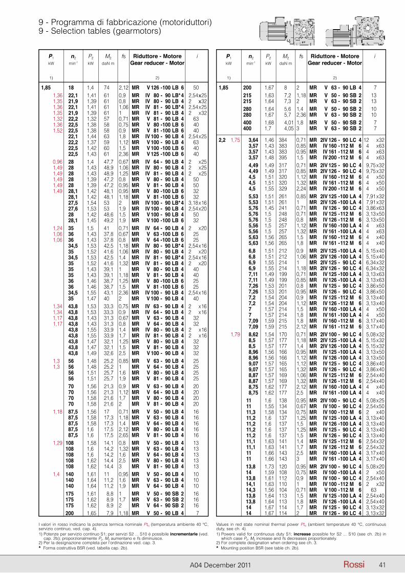
P1 n2 P2 M2 fs Riduttore - Motore i kW min-1 kW daN m Gear reducer - Motor
1) 2)
P1 n2 P2 M2 fs Riduttore - Motore i kW min-1 kW daN m Gear reducer - Motor
1) 2)
41A04 December 2011
9 - Programma di fabbricazione (motoriduttori)9 - Selection tables (gearmotors)
P1 n2 P2 M2 fs Riduttore - Motore i kW min-1 kW daN m Gear reducer - Motor
1) 2)
I valori in rosso indicano la potenza termica nominale PtN (temperatura ambiente 40 °C, servizio continuo, ved. cap. 4).1) Potenze per servizio continuo S1; per servizi S2 ... S10 è possibile incrementarle (ved.
cap. 2b); proporzionalmente P2, M2 aumentano e fs diminuisce.2) Per la designazione completa per l’ordinazione ved. cap. 3.* Forma costruttiva B5R (ved. tabella cap. 2b).
Values in red state nominal thermal power PtN (ambient temperature 40 °C, continuous duty, see ch. 4).1) Powers valid for continuous duty S1; increase possible for S2 ... S10 (see ch. 2b) in
which case P2, M2 increase and fs decreases proportionately.2) For complete designation when ordering see ch. 3.* Mounting position B5R (see table ch. 2b).
1,85 18 1,4 74 2,12 MR V 126 - 100 LB 6 50 1,36 22,1 1,41 61 0,9 MR IV 80 - 90 LB* 4 22,54 x 25 1,35 21,9 1,39 61 0,8 MR IV 80 - 90 LB 4 22 x 32 1,36 22,1 1,41 61 1,06 MR IV 81 - 90 LB* 4 22,54 x 25 1,35 21,9 1,39 61 1 MR IV 81 - 90 LB 4 22 x 32 1,32 22,2 1,32 57 0,71 MR V 81 - 90 LB 4 63 1,36 22,5 1,38 58 0,75 MR V 80 - 100 LB 6 40 1,52 22,5 1,38 58 0,9 MR V 81 - 100 LB 6 40 22,1 1,44 63 1,8 MR IV 100 - 90 LB 4 22,54 x 25 22,2 1,37 59 1,12 MR V 100 - 90 LB 4 63 22,5 1,42 60 1,5 MR V 100 - 100 LB 6 40 22,5 1,43 61 2,36 MR V 125 - 100 LB 6 40 0,96 28 1,4 47,7 0,67 MR IV 64 - 90 LB 4 22 x 25 1,49 28 1,43 48,9 1,06 MR IV 80 - 90 LB 4 22 x 25 1,49 28 1,43 48,9 1,25 MR IV 81 - 90 LB 4 22 x 25 1,49 28 1,39 47,2 0,8 MR V 80 - 90 LB 4 50 1,49 28 1,39 47,2 0,95 MR V 81 - 90 LB 4 50 1,49 28,1 1,42 48,1 0,95 MR V 80 - 100 LB 6 32 28,1 1,42 48,1 1,18 MR V 81 - 100 LB 6 32 27,5 1,54 53 2 MR IV 100 - 90 LB* 4 23,18 x 16 27,6 1,53 53 1,9 MR IV 100 - 90 LB 4 22,54 x 20 28 1,42 48,6 1,5 MR V 100 - 90 LB 4 50 28,1 1,45 49,2 1,9 MR V 100 - 100 LB 6 32 1,24 35 1,5 41 0,71 MR IV 64 - 90 LB 4 22 x 20 1,06 36 1,43 37,8 0,67 MR V 63 - 100 LB 6 25 1,06 36 1,43 37,8 0,8 MR V 64 - 100 LB 6 25 34,5 1,53 42,5 1,18 MR IV 80 - 90 LB* 4 22,54 x 16 35 1,52 41,6 1,06 MR IV 80 - 90 LB 4 22 x 20 34,5 1,53 42,5 1,4 MR IV 81 - 90 LB* 4 22,54 x 16 35 1,52 41,6 1,32 MR IV 81 - 90 LB 4 22 x 20 35 1,43 39,1 1 MR V 80 - 90 LB 4 40 35 1,43 39,1 1,18 MR V 81 - 90 LB 4 40 36 1,46 38,7 1,25 MR V 80 - 100 LB 6 25 36 1,46 38,7 1,5 MR V 81 - 100 LB 6 25 34,5 1,55 43,1 2,36 MR IV 100 - 90 LB 4 22,54 x 16 35 1,47 40 2 MR V 100 - 90 LB 4 40 1,34 43,8 1,53 33,3 0,75 MR IV 63 - 90 LB 4 22 x 16 1,34 43,8 1,53 33,3 0,9 MR IV 64 - 90 LB 4 22 x 16 1,17 43,8 1,43 31,3 0,67 MR V 63 - 90 LB 4 32 1,17 43,8 1,43 31,3 0,8 MR V 64 - 90 LB 4 32 43,8 1,55 33,9 1,4 MR IV 80 - 90 LB 4 22 x 16 43,8 1,55 33,9 1,7 MR IV 81 - 90 LB 4 22 x 16 43,8 1,47 32,1 1,25 MR V 80 - 90 LB 4 32 43,8 1,47 32,1 1,5 MR V 81 - 90 LB 4 32 43,8 1,49 32,6 2,5 MR V 100 - 90 LB 4 32 1,3 56 1,48 25,2 0,85 MR V 63 - 90 LB 4 25 1,3 56 1,48 25,2 1 MR V 64 - 90 LB 4 25 56 1,51 25,7 1,6 MR V 80 - 90 LB 4 25 56 1,51 25,7 1,9 MR V 81 - 90 LB 4 25 70 1,56 21,3 0,9 MR V 63 - 90 LB 4 20 70 1,56 21,3 1,12 MR V 64 - 90 LB 4 20 70 1,58 21,6 1,7 MR V 80 - 90 LB 4 20 70 1,58 21,6 2 MR V 81 - 90 LB 4 20 1,18 87,5 1,56 17 0,71 MR V 50 - 90 LB 4 16 87,5 1,58 17,3 1,18 MR V 63 - 90 LB 4 16 87,5 1,58 17,3 1,4 MR V 64 - 90 LB 4 16 87,5 1,6 17,5 2,12 MR V 80 - 90 LB 4 16 87,5 1,6 17,5 2,65 MR V 81 - 90 LB 4 16 1,29 108 1,58 14,1 0,8 MR V 50 - 90 LB 4 13 108 1,6 14,2 1,32 MR V 63 - 90 LB 4 13 108 1,6 14,2 1,6 MR V 64 - 90 LB 4 13 108 1,62 14,4 2,5 MR V 80 - 90 LB 4 13 108 1,62 14,4 3 MR V 81 - 90 LB 4 13 1,4 140 1,61 11 0,95 MR V 50 - 90 LB 4 10 140 1,64 11,2 1,6 MR V 63 - 90 LB 4 10 140 1,64 11,2 1,9 MR V 64 - 90 LB 4 10 175 1,61 8,8 1 MR V 50 - 90 SB 2 16 175 1,62 8,9 1,7 MR V 63 - 90 SB 2 16 175 1,62 8,9 2 MR V 64 - 90 SB 2 16 200 1,65 7,9 1,18 MR V 50 - 90 LB 4 7
P1 n2 P2 M2 fs Riduttore - Motore i kW min-1 kW daN m Gear reducer - Motor
1) 2)
1,85 200 1,67 8 2 MR V 63 - 90 LB 4 7 215 1,63 7,2 1,18 MR V 50 - 90 SB 2 13 215 1,64 7,3 2 MR V 63 - 90 SB 2 13 280 1,64 5,6 1,4 MR V 50 - 90 SB 2 10 280 1,67 5,7 2,36 MR V 63 - 90 SB 2 10 400 1,68 4,01 1,8 MR V 50 - 90 SB 2 7 400 1,7 4,05 3 MR V 63 - 90 SB 2 7
2,2 1,75 3,64 1,46 384 0,71 MR 2IV 126 - 90 LC 4 12 x 32 3,57 1,43 383 0,85 MR IV 160 - 112 M 6 24 x 63 3,57 1,43 383 0,95 MR IV 161 - 112 M 6 24 x 63 3,57 1,48 395 1,5 MR IV 200 - 112 M 6 24 x 63 4,49 1,49 317 0,71 MR 2IV 125 - 90 LC 4 29,75 x 32 4,49 1,49 317 0,85 MR 2IV 126 - 90 LC 4 29,75 x 32 4,5 1,51 320 1,12 MR IV 160 - 112 M 6 24 x 50 4,5 1,51 320 1,32 MR IV 161 - 112 M 6 24 x 50 4,5 1,55 329 2,24 MR IV 200 - 112 M 6 24 x 50 5,53 1,51 261 0,85 MR 2IV 125 - 100 LA 4 27,91 x 32 5,53 1,51 261 1 MR 2IV 126 - 100 LA 4 27,91 x 32 5,76 1,45 241 0,71 MR IV 126 - 90 LC 4 23,86 x 63 5,76 1,5 248 0,71 MR IV 125 - 112 M 6 23,13 x 50 5,76 1,5 248 0,8 MR IV 126 - 112 M 6 23,13 x 50 5,56 1,5 257 1,12 MR IV 160 - 100 LA 4 24 x 63 5,56 1,5 257 1,32 MR IV 161 - 100 LA 4 24 x 63 5,63 1,56 265 1,5 MR IV 160 - 112 M 6 24 x 40 5,63 1,56 265 1,8 MR IV 161 - 112 M 6 24 x 40 6,8 1,51 212 0,9 MR 2IV 125 - 100 LA 4 25,15 x 40 6,8 1,51 212 1,06 MR 2IV 126 - 100 LA 4 25,15 x 40 6,9 1,55 214 1 MR 2IV 125 - 90 LC 4 26,34 x 32 6,9 1,55 214 1,18 MR 2IV 126 - 90 LC 4 26,34 x 32 7,11 1,49 199 0,71 MR IV 125 - 100 LA 4 23,13 x 63 7,11 1,49 199 0,85 MR IV 126 - 100 LA 4 23,13 x 63 7,26 1,53 201 0,8 MR IV 125 - 90 LC 4 23,86 x 50 7,26 1,53 201 0,95 MR IV 126 - 90 LC 4 23,86 x 50 7,2 1,54 204 0,9 MR IV 125 - 112 M 6 23,13 x 40 7,2 1,54 204 1,12 MR IV 126 - 112 M 6 23,13 x 40 7 1,57 214 1,5 MR IV 160 - 100 LA 4 24 x 50 7 1,57 214 1,8 MR IV 161 - 100 LA 4 24 x 50 7,09 1,59 215 1,8 MR IV 160 - 112 M 6 23,17 x 40 7,09 1,59 215 2,12 MR IV 161 - 112 M 6 23,17 x 40 1,79 8,62 1,54 170 0,71 MR 2IV 100 - 90 LC 4 25,08 x 32 8,5 1,57 177 1,18 MR 2IV 125 - 100 LA 4 25,15 x 32 8,5 1,57 177 1,4 MR 2IV 126 - 100 LA 4 25,15 x 32 8,96 1,56 166 0,95 MR IV 125 - 100 LA 4 23,13 x 50 8,96 1,56 166 1,12 MR IV 126 - 100 LA 4 23,13 x 50 9,07 1,57 165 1,12 MR IV 125 - 90 LC 4 23,86 x 40 9,07 1,57 165 1,32 MR IV 126 - 90 LC 4 23,86 x 40 8,87 1,57 169 1,06 MR IV 125 - 112 M 6 22,54 x 40 8,87 1,57 169 1,32 MR IV 126 - 112 M 6 22,54 x 40 8,75 1,62 177 2,12 MR IV 160 - 100 LA 4 24 x 40 8,75 1,62 177 2,5 MR IV 161 - 100 LA 4 24 x 40 11 1,6 138 0,95 MR 2IV 100 - 90 LC 4 25,08 x 25 11 1,55 134 0,67 MR IV 100 - 90 LC 4 22,54 x 50 11,3 1,58 134 0,75 MR IV 100 - 112 M 6 22 x 40 11,2 1,6 137 1,25 MR IV 125 - 100 LA 4 23,13 x 40 11,2 1,6 137 1,5 MR IV 126 - 100 LA 4 23,13 x 40 11,2 1,6 137 1,25 MR IV 125 - 90 LC 4 23,13 x 40 11,2 1,6 137 1,5 MR IV 126 - 90 LC 4 23,13 x 40 11,1 1,63 141 1,4 MR IV 125 - 112 M 6 22,54 x 32 11,1 1,63 141 1,7 MR IV 126 - 112 M 6 22,54 x 32 11 1,66 143 2,5 MR IV 160 - 100 LA 4 23,17 x 40 11 1,66 143 3 MR IV 161 - 100 LA 4 23,17 x 40 13,8 1,73 120 0,95 MR 2IV 100 - 90 LC 4 25,08 x 20 14 1,59 108 0,75 MR IV 100 - 100 LA 4 22 x 50 13,8 1,61 112 0,9 MR IV 100 - 90 LC 4 22,54 x 40 14,1 1,63 110 1 MR IV 100 - 112 M 6 22 x 32 14,3 1,56 104 0,71 MR V 100 - 112 M 6 63 13,8 1,64 113 1,5 MR IV 125 - 100 LA 4 22,54 x 40 13,8 1,64 113 1,8 MR IV 126 - 100 LA 4 22,54 x 40 14 1,67 114 1,7 MR IV 125 - 90 LC 4 23,13 x 32 14 1,67 114 2 MR IV 126 - 90 LC 4 23,13 x 32
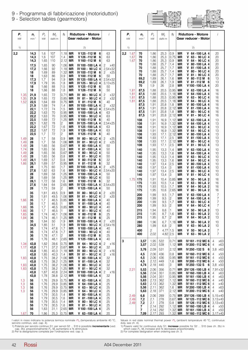
P1 n2 P2 M2 fs Riduttore - Motore i kW min-1 kW daN m Gear reducer - Motor
1) 2)
P1 n2 P2 M2 fs Riduttore - Motore i kW min-1 kW daN m Gear reducer - Motor
1) 2)
42 A04 December 2011
9 - Programma di fabbricazione (motoriduttori)9 - Selection tables (gearmotors)
P1 n2 P2 M2 fs Riduttore - Motore i kW min-1 kW daN m Gear reducer - Motor
1) 2)
I valori in rosso indicano la potenza termica nominale PtN (temperatura ambiente 40 °C, servizio continuo, ved. cap. 4).1) Potenze per servizio continuo S1; per servizi S2 ... S10 è possibile incrementarle (ved.
cap. 2b); proporzionalmente P2, M2 aumentano e fs diminuisce.2) Per la designazione completa per l’ordinazione ved. cap. 3.
Values in red state nominal thermal power PtN (ambient temperature 40 °C, continuous duty, see ch. 4).1) Powers valid for continuous duty S1; increase possible for S2 ... S10 (see ch. 2b) in
which case P2, M2 increase and fs decreases proportionately.2) For complete designation when ordering see ch. 3.
2,2 14,3 1,6 107 1,18 MR V 125 - 112 M 6 63 14,3 1,6 107 1,4 MR V 126 - 112 M 6 63 14,3 1,65 110 2,12 MR V 160 - 112 M 6 63 17,5 1,65 90 1,06 MR IV 100 - 100 LA 4 22 x 40 17,2 1,66 92 1,18 MR IV 100 - 90 LC 4 22,54 x 32 18 1,69 89 1,32 MR IV 100 - 112 M 6 22 x 25 18 1,63 86 0,9 MR V 100 - 112 M 6 50 17,3 1,7 94 1,9 MR IV 125 - 100 LA 4 22,54 x 32 17,9 1,79 95 1,8 MR IV 125 - 90 LC 4 23,13 x 25 18 1,66 88 1,5 MR V 125 - 112 M 6 50 18 1,66 88 1,8 MR V 126 - 112 M 6 50 1,35 21,9 1,65 72 0,71 MR IV 80 - 90 LC 4 22 x 32 1,35 21,9 1,65 72 0,85 MR IV 81 - 90 LC 4 22 x 32 1,52 22,5 1,64 69 0,75 MR V 81 - 112 M 6 40 21,9 1,69 74 1,4 MR IV 100 - 100 LA 4 22 x 32 22,1 1,72 74 1,5 MR IV 100 - 90 LC 4 22,54 x 25 22,2 1,63 70 0,95 MR V 100 - 100 LA 4 63 22,2 1,63 70 0,95 MR V 100 - 90 LC 4 63 22,5 1,69 72 1,25 MR V 100 - 112 M 6 40 22,1 1,82 78 2 MR IV 125 - 100 LA 4 22,54 x 25 22,2 1,67 72 1,6 MR V 125 - 100 LA 4 63 22,2 1,67 72 1,9 MR V 126 - 100 LA 4 63 22,5 1,7 72 2 MR V 125 - 112 M 6 40 1,49 28 1,7 58 0,9 MR IV 80 - 90 LC 4 22 x 25 1,49 28 1,7 58 1,06 MR IV 81 - 90 LC 4 22 x 25 1,49 28 1,65 56 0,67 MR V 80 - 100 LA 4 50 1,74 28 1,65 56 0,8 MR V 81 - 100 LA 4 50 1,49 28 1,65 56 0,67 MR V 80 - 90 LC 4 50 1,49 28 1,65 56 0,8 MR V 81 - 90 LC 4 50 1,49 28,1 1,69 57 0,8 MR V 80 - 112 M 6 32 1,66 28,1 1,69 57 0,95 MR V 81 - 112 M 6 32 28 1,75 60 1,7 MR IV 100 - 100 LA 4 22 x 25 27,6 1,82 63 1,6 MR IV 100 - 90 LC 4 22,54 x 20 28 1,69 58 1,25 MR V 100 - 100 LA 4 50 28 1,69 58 1,25 MR V 100 - 90 LC 4 50 28,1 1,72 58 1,6 MR V 100 - 112 M 6 32 27,6 1,84 64 2,65 MR IV 125 - 100 LA 4 22,54 x 20 28 1,73 59 2 MR V 125 - 100 LA 4 50 35 1,81 49,5 0,9 MR IV 80 - 90 LC 4 22 x 20 35 1,81 49,5 1,06 MR IV 81 - 90 LC 4 22 x 20 1,66 35 1,7 46,5 0,85 MR V 80 - 100 LA 4 40 35 1,7 46,5 1 MR V 81 - 100 LA 4 40 1,66 35 1,7 46,5 0,85 MR V 80 - 90 LC 4 40 1,66 35 1,7 46,5 1 MR V 81 - 90 LC 4 40 1,65 36 1,74 46,1 1,06 MR V 80 - 112 M 6 25 1,84 36 1,74 46,1 1,25 MR V 81 - 112 M 6 25 35 1,84 50 1,9 MR IV 100 - 100 LA 4 22 x 20 34,5 1,85 51 1,9 MR IV 100 - 90 LC 4 22,54 x 16 35 1,74 47,6 1,7 MR V 100 - 100 LA 4 40 35 1,74 47,6 1,7 MR V 100 - 90 LC 4 40 36 1,78 47,1 2 MR V 100 - 112 M 6 25 35 1,76 48,1 2,65 MR V 125 - 100 LA 4 40 1,34 43,8 1,82 39,6 0,75 MR IV 64 - 90 LC 4 22 x 16 1,17 43,8 1,71 37,2 0,67 MR V 64 - 90 LC 4 32 43,8 1,85 40,3 1,18 MR IV 80 - 90 LC 4 22 x 16 43,8 1,85 40,3 1,4 MR IV 81 - 90 LC 4 22 x 16 1,83 43,8 1,75 38,2 1,06 MR V 80 - 100 LA 4 32 43,8 1,75 38,2 1,25 MR V 81 - 100 LA 4 32 1,83 43,8 1,75 38,2 1,06 MR V 80 - 90 LC 4 32 1,83 43,8 1,75 38,2 1,25 MR V 81 - 90 LC 4 32 43,8 1,87 40,8 2,24 MR IV 100 - 100 LA 4 22 x 16 43,8 1,78 38,8 2,12 MR V 100 - 100 LA 4 32 1,3 56 1,76 29,9 0,75 MR V 63 - 100 LA 4 25 1,3 56 1,76 29,9 0,85 MR V 64 - 100 LA 4 25 1,3 56 1,76 29,9 0,75 MR V 63 - 90 LC 4 25 1,3 56 1,76 29,9 0,85 MR V 64 - 90 LC 4 25 56 1,79 30,5 1,4 MR V 80 - 100 LA 4 25 56 1,79 30,5 1,6 MR V 81 - 100 LA 4 25 56 1,79 30,5 1,4 MR V 80 - 90 LC 4 25 56 1,79 30,5 1,6 MR V 81 - 90 LC 4 25 56 1,83 31,1 2,65 MR V 100 - 100 LA 4 25 1,67 70 1,86 25,3 0,75 MR V 63 - 100 LA 4 20
P1 n2 P2 M2 fs Riduttore - Motore i kW min-1 kW daN m Gear reducer - Motor
1) 2)
2,2 1,67 70 1,86 25,3 0,9 MR V 64 - 100 LA 4 20 1,67 70 1,86 25,3 0,75 MR V 63 - 90 LC 4 20 1,67 70 1,86 25,3 0,9 MR V 64 - 90 LC 4 20 70 1,88 25,7 1,4 MR V 80 - 100 LA 4 20 70 1,88 25,7 1,7 MR V 81 - 100 LA 4 20 70 1,88 25,7 1,4 MR V 80 - 90 LC 4 20 70 1,88 25,7 1,7 MR V 81 - 90 LC 4 20 69,2 1,89 26,1 1,6 MR V 80 - 112 M 6 13 69,2 1,89 26,1 1,9 MR V 81 - 112 M 6 13 70 1,9 26 2,8 MR V 100 - 100 LA 4 20 1,81 87,5 1,88 20,5 0,95 MR V 63 - 100 LA 4 16 1,81 87,5 1,88 20,5 1,18 MR V 64 - 100 LA 4 16 1,81 87,5 1,88 20,5 0,95 MR V 63 - 90 LC 4 16 1,81 87,5 1,88 20,5 1,18 MR V 64 - 90 LC 4 16 87,5 1,91 20,8 1,8 MR V 80 - 100 LA 4 16 87,5 1,91 20,8 2,12 MR V 81 - 100 LA 4 16 87,5 1,91 20,8 1,8 MR V 80 - 90 LC 4 16 87,5 1,91 20,8 2,12 MR V 81 - 90 LC 4 16 108 1,91 16,9 1,12 MR V 63 - 100 LA 4 13 108 1,91 16,9 1,32 MR V 64 - 100 LA 4 13 108 1,91 16,9 1,12 MR V 63 - 90 LC 4 13 108 1,91 16,9 1,32 MR V 64 - 90 LC 4 13 108 1,93 17,1 2,12 MR V 80 - 100 LA 4 13 108 1,93 17,1 2,5 MR V 81 - 100 LA 4 13 108 1,93 17,1 2,12 MR V 80 - 90 LC 4 13 108 1,93 17,1 2,5 MR V 81 - 90 LC 4 13 140 1,95 13,3 1,4 MR V 63 - 100 LA 4 10 140 1,95 13,3 1,6 MR V 64 - 100 LA 4 10 140 1,95 13,3 1,4 MR V 63 - 90 LC 4 10 140 1,95 13,3 1,6 MR V 64 - 90 LC 4 10 140 1,97 13,4 2,5 MR V 80 - 100 LA 4 10 140 1,97 13,4 3 MR V 81 - 100 LA 4 10 140 1,97 13,4 2,5 MR V 80 - 90 LC 4 10 140 1,97 13,4 3 MR V 81 - 90 LC 4 10 1,75 175 1,91 10,4 0,85 MR V 50 - 90 LA 2 16 175 1,93 10,5 1,4 MR V 63 - 90 LA 2 16 175 1,93 10,5 1,7 MR V 64 - 90 LA 2 16 175 1,95 10,6 2,65 MR V 80 - 90 LA 2 16 200 1,99 9,5 1,7 MR V 63 - 100 LA 4 7 200 1,99 9,5 2 MR V 64 - 100 LA 4 7 200 1,99 9,5 1,7 MR V 63 - 90 LC 4 7 200 1,99 9,5 2 MR V 64 - 90 LC 4 7 215 1,94 8,6 1 MR V 50 - 90 LA 2 13 215 1,95 8,7 1,6 MR V 63 - 90 LA 2 13 215 1,95 8,7 2 MR V 64 - 90 LA 2 13 280 1,96 6,7 1,18 MR V 50 - 90 LA 2 10 280 1,99 6,8 2 MR V 63 - 90 LA 2 10 400 2 4,77 1,5 MR V 50 - 90 LA 2 7 400 2,02 4,82 2,5 MR V 63 - 90 LA 2 7
3 3,57 1,95 522 0,71 MR IV 161 - 112 MC 6 24 x 63 3,57 2,02 539 1,12 MR IV 200 - 112 MC 6 24 x 63 3,76 2,09 531 2,12 MR IV 250 - 132 S 6 23,8 x 63 4,5 2,06 436 0,8 MR IV 160 - 112 MC 6 24 x 50 4,5 2,06 436 0,95 MR IV 161 - 112 MC 6 24 x 50 4,5 2,12 449 1,6 MR IV 200 - 112 MC 6 24 x 50 4,74 2,18 440 3 MR IV 250 - 132 S 6 23,8 x 50 2,21 5,53 2,06 356 0,71 MR 2IV 126 - 100 LB 4 27,91 x 32 5,56 2,04 351 0,85 MR IV 160 - 100 LB 4 24 x 63 5,56 2,04 351 0,95 MR IV 161 - 100 LB 4 24 x 63 5,63 2,13 362 1,12 MR IV 160 - 112 MC 6 24 x 40 5,63 2,13 362 1,32 MR IV 161 - 112 MC 6 24 x 40 5,56 2,11 362 1,6 MR IV 200 - 100 LB 4 24 x 63 5,63 2,18 371 2,12 MR IV 200 - 112 MC 6 24 x 40 2,49 6,8 2,06 289 0,75 MR 2IV 126 - 100 LB 4 25,15 x 40 2,49 7,2 2,1 278 0,67 MR IV 125 - 112 MC 6 23,13 x 40 2,49 7,2 2,1 278 0,8 MR IV 126 - 112 MC 6 23,13 x 40 7 2,14 292 1,12 MR IV 160 - 100 LB 4 24 x 50 7 2,14 292 1,32 MR IV 161 - 100 LB 4 24 x 50 7,09 2,17 293 1,32 MR IV 160 - 112 MC 6 23,17 x 40
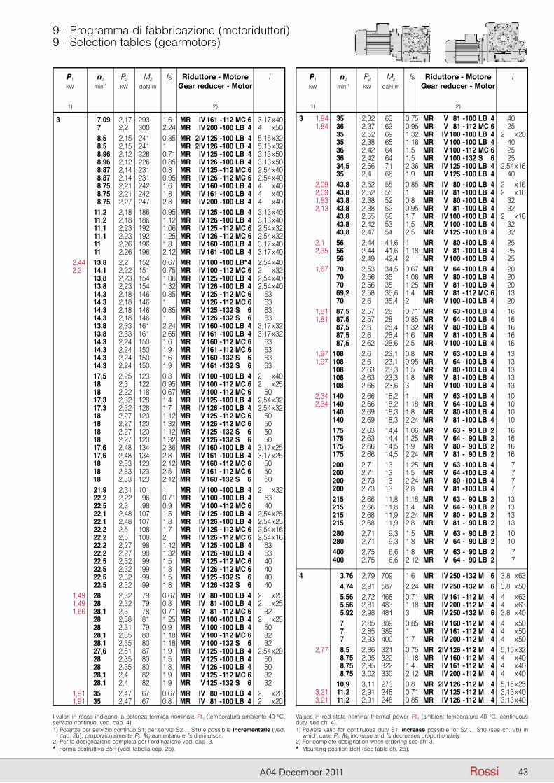
P1 n2 P2 M2 fs Riduttore - Motore i kW min-1 kW daN m Gear reducer - Motor
1) 2)
P1 n2 P2 M2 fs Riduttore - Motore i kW min-1 kW daN m Gear reducer - Motor
1) 2)
43A04 December 2011
9 - Programma di fabbricazione (motoriduttori)9 - Selection tables (gearmotors)
P1 n2 P2 M2 fs Riduttore - Motore i kW min-1 kW daN m Gear reducer - Motor
1) 2)
I valori in rosso indicano la potenza termica nominale PtN (temperatura ambiente 40 °C, servizio continuo, ved. cap. 4).1) Potenze per servizio continuo S1; per servizi S2 ... S10 è possibile incrementarle (ved.
cap. 2b); proporzionalmente P2, M2 aumentano e fs diminuisce.2) Per la designazione completa per l’ordinazione ved. cap. 3.* Forma costruttiva B5R (ved. tabella cap. 2b).
Values in red state nominal thermal power PtN (ambient temperature 40 °C, continuous duty, see ch. 4).1) Powers valid for continuous duty S1; increase possible for S2 ... S10 (see ch. 2b) in
which case P2, M2 increase and fs decreases proportionately.2) For complete designation when ordering see ch. 3.* Mounting position B5R (see table ch. 2b).
3 7,09 2,17 293 1,6 MR IV 161 - 112 MC 6 23,17 x 40 7 2,2 300 2,24 MR IV 200 - 100 LB 4 24 x 50 8,5 2,15 241 0,85 MR 2IV 125 - 100 LB 4 25,15 x 32 8,5 2,15 241 1 MR 2IV 126 - 100 LB 4 25,15 x 32 8,96 2,12 226 0,71 MR IV 125 - 100 LB 4 23,13 x 50 8,96 2,12 226 0,85 MR IV 126 - 100 LB 4 23,13 x 50 8,87 2,14 231 0,8 MR IV 125 - 112 MC 6 22,54 x 40 8,87 2,14 231 0,95 MR IV 126 - 112 MC 6 22,54 x 40 8,75 2,21 242 1,6 MR IV 160 - 100 LB 4 24 x 40 8,75 2,21 242 1,8 MR IV 161 - 100 LB 4 24 x 40 8,75 2,27 247 2,8 MR IV 200 - 100 LB 4 24 x 40 11,2 2,18 186 0,95 MR IV 125 - 100 LB 4 23,13 x 40 11,2 2,18 186 1,12 MR IV 126 - 100 LB 4 23,13 x 40 11,1 2,23 192 1,06 MR IV 125 - 112 MC 6 22,54 x 32 11,1 2,23 192 1,25 MR IV 126 - 112 MC 6 22,54 x 32 11 2,26 196 1,8 MR IV 160 - 100 LB 4 23,17 x 40 11 2,26 196 2,12 MR IV 161 - 100 LB 4 23,17 x 40 2,44 13,8 2,2 152 0,67 MR IV 100 - 100 LB* 4 22,54 x 40 2,3 14,1 2,22 151 0,75 MR IV 100 - 112 MC 6 22 x 32 13,8 2,23 154 1,06 MR IV 125 - 100 LB 4 22,54 x 40 13,8 2,23 154 1,32 MR IV 126 - 100 LB 4 22,54 x 40 14,3 2,18 146 0,85 MR V 125 - 112 MC 6 63 14,3 2,18 146 1 MR V 126 - 112 MC 6 63 14,3 2,18 146 0,85 MR V 125 - 132 S 6 63 14,3 2,18 146 1 MR V 126 - 132 S 6 63 13,8 2,33 161 2,24 MR IV 160 - 100 LB 4 23,17 x 32 13,8 2,33 161 2,65 MR IV 161 - 100 LB 4 23,17 x 32 14,3 2,24 150 1,6 MR V 160 - 112 MC 6 63 14,3 2,24 150 1,9 MR V 161 - 112 MC 6 63 14,3 2,24 150 1,6 MR V 160 - 132 S 6 63 14,3 2,24 150 1,9 MR V 161 - 132 S 6 63 17,5 2,25 123 0,8 MR IV 100 - 100 LB 4 22 x 40 18 2,3 122 0,95 MR IV 100 - 112 MC 6 22 x 25 18 2,22 118 0,67 MR V 100 - 112 MC 6 50 17,3 2,32 128 1,4 MR IV 125 - 100 LB 4 22,54 x 32 17,3 2,32 128 1,7 MR IV 126 - 100 LB 4 22,54 x 32 18 2,27 120 1,12 MR V 125 - 112 MC 6 50 18 2,27 120 1,32 MR V 126 - 112 MC 6 50 18 2,27 120 1,12 MR V 125 - 132 S 6 50 18 2,27 120 1,32 MR V 126 - 132 S 6 50 17,6 2,48 134 2,36 MR IV 160 - 100 LB 4 23,17 x 25 17,6 2,48 134 2,8 MR IV 161 - 100 LB 4 23,17 x 25 18 2,33 123 2,12 MR V 160 - 112 MC 6 50 18 2,33 123 2,5 MR V 161 - 112 MC 6 50 18 2,33 123 2,12 MR V 160 - 132 S 6 50 21,9 2,31 101 1 MR IV 100 - 100 LB 4 22 x 32 22,2 2,22 96 0,71 MR V 100 - 100 LB 4 63 22,5 2,3 98 0,9 MR V 100 - 112 MC 6 40 22,1 2,48 107 1,5 MR IV 125 - 100 LB 4 22,54 x 25 22,1 2,48 107 1,8 MR IV 126 - 100 LB 4 22,54 x 25 22,2 2,5 108 1,7 MR IV 125 - 112 MC 6 22,54 x 16 22,2 2,5 108 2 MR IV 126 - 112 MC 6 22,54 x 16 22,2 2,27 98 1,12 MR V 125 - 100 LB 4 63 22,2 2,27 98 1,32 MR V 126 - 100 LB 4 63 22,5 2,32 99 1,5 MR V 125 - 112 MC 6 40 22,5 2,32 99 1,8 MR V 126 - 112 MC 6 40 22,5 2,32 99 1,5 MR V 125 - 132 S 6 40 22,5 2,32 99 1,8 MR V 126 - 132 S 6 40 1,49 28 2,32 79 0,67 MR IV 80 - 100 LB 4 22 x 25 1,49 28 2,32 79 0,8 MR IV 81 - 100 LB 4 22 x 25 1,66 28,1 2,3 78 0,71 MR V 81 - 112 MC 6 32 28 2,38 81 1,25 MR IV 100 - 100 LB 4 22 x 25 28 2,31 79 0,9 MR V 100 - 100 LB 4 50 28,1 2,35 80 1,18 MR V 100 - 112 MC 6 32 28,1 2,35 80 1,18 MR V 100 - 132 S 6 32 27,6 2,51 87 1,9 MR IV 125 - 100 LB 4 22,54 x 20 28 2,35 80 1,5 MR V 125 - 100 LB 4 50 28 2,35 80 1,8 MR V 126 - 100 LB 4 50 28,1 2,4 82 1,9 MR V 125 - 112 MC 6 32 28,1 2,4 82 1,9 MR V 125 - 132 S 6 32 1,91 35 2,47 67 0,67 MR IV 80 - 100 LB 4 22 x 20 1,91 35 2,47 67 0,8 MR IV 81 - 100 LB 4 22 x 20
P1 n2 P2 M2 fs Riduttore - Motore i kW min-1 kW daN m Gear reducer - Motor
1) 2) 3 1,94 35 2,32 63 0,75 MR V 81 - 100 LB 4 40 1,84 36 2,37 63 0,95 MR V 81 - 112 MC 6 25 35 2,52 69 1,32 MR IV 100 - 100 LB 4 22 x 20 35 2,38 65 1,18 MR V 100 - 100 LB 4 40 36 2,42 64 1,5 MR V 100 - 112 MC 6 25 36 2,42 64 1,5 MR V 100 - 132 S 6 25 34,5 2,56 71 2,36 MR IV 125 - 100 LB 4 22,54 x 16 35 2,4 66 1,9 MR V 125 - 100 LB 4 40 2,09 43,8 2,52 55 0,85 MR IV 80 - 100 LB 4 22 x 16 2,09 43,8 2,52 55 1 MR IV 81 - 100 LB 4 22 x 16 1,83 43,8 2,38 52 0,8 MR V 80 - 100 LB 4 32 2,13 43,8 2,38 52 0,95 MR V 81 - 100 LB 4 32 43,8 2,55 56 1,7 MR IV 100 - 100 LB 4 22 x 16 43,8 2,42 53 1,5 MR V 100 - 100 LB 4 32 43,8 2,47 54 2,5 MR V 125 - 100 LB 4 32 2,1 56 2,44 41,6 1 MR V 80 - 100 LB 4 25 2,35 56 2,44 41,6 1,18 MR V 81 - 100 LB 4 25 56 2,49 42,4 2 MR V 100 - 100 LB 4 25 1,67 70 2,53 34,5 0,67 MR V 64 - 100 LB 4 20 70 2,56 35 1,06 MR V 80 - 100 LB 4 20 70 2,56 35 1,25 MR V 81 - 100 LB 4 20 69,2 2,58 35,6 1,4 MR V 81 - 112 MC 6 13 70 2,6 35,4 2 MR V 100 - 100 LB 4 20 1,81 87,5 2,57 28 0,71 MR V 63 - 100 LB 4 16 1,81 87,5 2,57 28 0,85 MR V 64 - 100 LB 4 16 87,5 2,6 28,4 1,32 MR V 80 - 100 LB 4 16 87,5 2,6 28,4 1,6 MR V 81 - 100 LB 4 16 87,5 2,62 28,6 2,5 MR V 100 - 100 LB 4 16 1,97 108 2,6 23,1 0,8 MR V 63 - 100 LB 4 13 1,97 108 2,6 23,1 0,95 MR V 64 - 100 LB 4 13 108 2,63 23,3 1,5 MR V 80 - 100 LB 4 13 108 2,63 23,3 1,8 MR V 81 - 100 LB 4 13 108 2,66 23,6 3 MR V 100 - 100 LB 4 13 2,34 140 2,66 18,2 1 MR V 63 - 100 LB 4 10 2,34 140 2,66 18,2 1,18 MR V 64 - 100 LB 4 10 140 2,69 18,3 1,8 MR V 80 - 100 LB 4 10 140 2,69 18,3 2,24 MR V 81 - 100 LB 4 10 175 2,63 14,4 1,06 MR V 63 - 90 LB 2 16 175 2,63 14,4 1,25 MR V 64 - 90 LB 2 16 175 2,66 14,5 1,9 MR V 80 - 90 LB 2 16 175 2,66 14,5 2,24 MR V 81 - 90 LB 2 16 200 2,71 13 1,25 MR V 63 - 100 LB 4 7 200 2,71 13 1,5 MR V 64 - 100 LB 4 7 200 2,73 13 2,24 MR V 80 - 100 LB 4 7 200 2,73 13 2,8 MR V 81 - 100 LB 4 7 215 2,66 11,8 1,18 MR V 63 - 90 LB 2 13 215 2,66 11,8 1,4 MR V 64 - 90 LB 2 13 215 2,68 11,9 2,24 MR V 80 - 90 LB 2 13 215 2,68 11,9 2,8 MR V 81 - 90 LB 2 13 280 2,71 9,3 1,5 MR V 63 - 90 LB 2 10 280 2,71 9,3 1,8 MR V 64 - 90 LB 2 10 400 2,75 6,6 1,8 MR V 63 - 90 LB 2 7 400 2,75 6,6 2,12 MR V 64 - 90 LB 2 7
4 3,76 2,79 709 1,6 MR IV 250 - 132 M 6 23,8 x 63 4,74 2,91 587 2,24 MR IV 250 - 132 M 6 23,8 x 50 5,56 2,72 468 0,71 MR IV 161 - 112 M 4 24 x 63 5,56 2,81 483 1,18 MR IV 200 - 112 M 4 24 x 63 5,92 2,98 481 3 MR IV 250 - 132 M 6 23,8 x 40 7 2,85 389 0,85 MR IV 160 - 112 M 4 24 x 50 7 2,85 389 1 MR IV 161 - 112 M 4 24 x 50 7 2,93 400 1,7 MR IV 200 - 112 M 4 24 x 50 2,77 8,5 2,86 321 0,75 MR 2IV 126 - 112 M 4 25,15 x 32 8,75 2,95 322 1,18 MR IV 160 - 112 M 4 24 x 40 8,75 2,95 322 1,4 MR IV 161 - 112 M 4 24 x 40 8,75 3,02 330 2,12 MR IV 200 - 112 M 4 24 x 40 10,9 3,11 273 0,8 MR 2IV 126 - 112 M 4 25,15 x 25 3,21 11,2 2,91 248 0,71 MR IV 125 - 112 M 4 23,13 x 40 3,21 11,2 2,91 248 0,85 MR IV 126 - 112 M 4 23,13 x 40
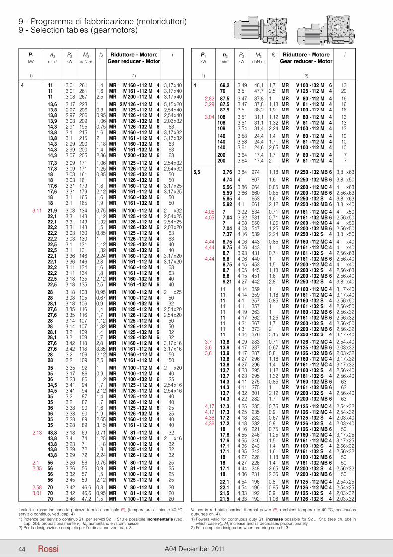
P1 n2 P2 M2 fs Riduttore - Motore i kW min-1 kW daN m Gear reducer - Motor
1) 2)
P1 n2 P2 M2 fs Riduttore - Motore i kW min-1 kW daN m Gear reducer - Motor
1) 2)
44 A04 December 2011
9 - Programma di fabbricazione (motoriduttori)9 - Selection tables (gearmotors)
P1 n2 P2 M2 fs Riduttore - Motore i kW min-1 kW daN m Gear reducer - Motor
1) 2)
I valori in rosso indicano la potenza termica nominale PtN (temperatura ambiente 40 °C, servizio continuo, ved. cap. 4).1) Potenze per servizio continuo S1; per servizi S2 ... S10 è possibile incrementarle (ved.
cap. 2b); proporzionalmente P2, M2 aumentano e fs diminuisce.2) Per la designazione completa per l’ordinazione ved. cap. 3.
Values in red state nominal thermal power PtN (ambient temperature 40 °C, continuous duty, see ch. 4).1) Powers valid for continuous duty S1; increase possible for S2 ... S10 (see ch. 2b) in
which case P2, M2 increase and fs decreases proportionately.2) For complete designation when ordering see ch. 3.
4 11 3,01 261 1,4 MR IV 160 - 112 M 4 23,17 x 40 11 3,01 261 1,6 MR IV 161 - 112 M 4 23,17 x 40 11 3,08 267 2,5 MR IV 200 - 112 M 4 23,17 x 40 13,6 3,17 223 1 MR 2IV 126 - 112 M 4 25,15 x 20 13,8 2,97 206 0,8 MR IV 125 - 112 M 4 22,54 x 40 13,8 2,97 206 0,95 MR IV 126 - 112 M 4 22,54 x 40 13,9 3,03 209 1,06 MR IV 126 - 132 M 6 22,03 x 32 14,3 2,91 195 0,75 MR V 126 - 132 M 6 63 13,8 3,1 215 1,6 MR IV 160 - 112 M 4 23,17 x 32 13,8 3,1 215 2 MR IV 161 - 112 M 4 23,17 x 32 14,3 2,99 200 1,18 MR V 160 - 132 M 6 63 14,3 2,99 200 1,4 MR V 161 - 132 M 6 63 14,3 3,07 205 2,36 MR V 200 - 132 M 6 63 17,3 3,09 171 1,06 MR IV 125 - 112 M 4 22,54 x 32 17,3 3,09 171 1,25 MR IV 126 - 112 M 4 22,54 x 32 18 3,03 161 0,85 MR V 125 - 132 M 6 50 18 3,03 161 1 MR V 126 - 132 M 6 50 17,6 3,31 179 1,8 MR IV 160 - 112 M 4 23,17 x 25 17,6 3,31 179 2,12 MR IV 161 - 112 M 4 23,17 x 25 18 3,1 165 1,6 MR V 160 - 132 M 6 50 18 3,1 165 1,9 MR V 161 - 132 M 6 50 3,11 21,9 3,08 134 0,75 MR IV 100 - 112 M 4 22 x 32 22,1 3,3 143 1,12 MR IV 125 - 112 M 4 22,54 x 25 22,1 3,3 143 1,32 MR IV 126 - 112 M 4 22,54 x 25 22,2 3,31 143 1,5 MR IV 126 - 132 M 6 22,03 x 20 22,2 3,03 130 0,85 MR V 125 - 112 M 4 63 22,2 3,03 130 1 MR V 126 - 112 M 4 63 22,5 3,1 131 1,12 MR V 125 - 132 M 6 40 22,5 3,1 131 1,32 MR V 126 - 132 M 6 40 22,1 3,36 146 2,24 MR IV 160 - 112 M 4 23,17 x 20 22,1 3,36 146 2,8 MR IV 161 - 112 M 4 23,17 x 20 22,2 3,11 134 1,6 MR V 160 - 112 M 4 63 22,2 3,11 134 1,8 MR V 161 - 112 M 4 63 22,5 3,18 135 2,12 MR V 160 - 132 M 6 40 22,5 3,18 135 2,5 MR V 161 - 132 M 6 40 28 3,18 108 0,95 MR IV 100 - 112 M 4 22 x 25 28 3,08 105 0,67 MR V 100 - 112 M 4 50 28,1 3,13 106 0,9 MR V 100 - 132 M 6 32 27,6 3,35 116 1,4 MR IV 125 - 112 M 4 22,54 x 20 27,6 3,35 116 1,7 MR IV 126 - 112 M 4 22,54 x 20 28 3,14 107 1,12 MR V 125 - 112 M 4 50 28 3,14 107 1,32 MR V 126 - 112 M 4 50 28,1 3,2 109 1,4 MR V 125 - 132 M 6 32 28,1 3,2 109 1,7 MR V 126 - 132 M 6 32 27,6 3,42 118 2,8 MR IV 160 - 112 M 4 23,17 x 16 27,6 3,42 118 3,35 MR IV 161 - 112 M 4 23,17 x 16 28 3,2 109 2,12 MR V 160 - 112 M 4 50 28 3,2 109 2,5 MR V 161 - 112 M 4 50 35 3,35 92 1 MR IV 100 - 112 M 4 22 x 20 35 3,17 86 0,9 MR V 100 - 112 M 4 40 36 3,23 86 1,12 MR V 100 - 132 M 6 25 34,5 3,41 94 1,7 MR IV 125 - 112 M 4 22,54 x 16 34,5 3,41 94 2,12 MR IV 126 - 112 M 4 22,54 x 16 35 3,2 87 1,4 MR V 125 - 112 M 4 40 35 3,2 87 1,7 MR V 126 - 112 M 4 40 36 3,38 90 1,6 MR V 125 - 132 M 6 25 36 3,38 90 1,9 MR V 126 - 132 M 6 25 35 3,28 89 2,65 MR V 160 - 112 M 4 40 35 3,28 89 3,15 MR V 161 - 112 M 4 40 2,13 43,8 3,18 69 0,71 MR V 81 - 112 M 4 32 43,8 3,4 74 1,25 MR IV 100 - 112 M 4 22 x 16 43,8 3,23 71 1,18 MR V 100 - 112 M 4 32 43,8 3,29 72 1,8 MR V 125 - 112 M 4 32 43,8 3,29 72 2,24 MR V 126 - 112 M 4 32 2,1 56 3,26 56 0,75 MR V 80 - 112 M 4 25 2,35 56 3,26 56 0,9 MR V 81 - 112 M 4 25 56 3,32 57 1,5 MR V 100 - 112 M 4 25 56 3,45 59 2,12 MR V 125 - 112 M 4 25 2,58 70 3,42 46,6 0,8 MR V 80 - 112 M 4 20 3,01 70 3,42 46,6 0,95 MR V 81 - 112 M 4 20 70 3,46 47,2 1,5 MR V 100 - 112 M 4 20
P1 n2 P2 M2 fs Riduttore - Motore i kW min-1 kW daN m Gear reducer - Motor
1) 2)
4 69,2 3,49 48,1 1,7 MR V 100 - 132 M 6 13 70 3,5 47,7 2,5 MR V 125 - 112 M 4 20 2,82 87,5 3,47 37,8 1 MR V 80 - 112 M 4 16 3,29 87,5 3,47 37,8 1,18 MR V 81 - 112 M 4 16 87,5 3,5 38,2 1,9 MR V 100 - 112 M 4 16 3,04 108 3,51 31,1 1,12 MR V 80 - 112 M 4 13 108 3,51 31,1 1,32 MR V 81 - 112 M 4 13 108 3,54 31,4 2,24 MR V 100 - 112 M 4 13 140 3,58 24,4 1,4 MR V 80 - 112 M 4 10 140 3,58 24,4 1,7 MR V 81 - 112 M 4 10 140 3,61 24,6 2,65 MR V 100 - 112 M 4 10 200 3,64 17,4 1,7 MR V 80 - 112 M 4 7 200 3,64 17,4 2 MR V 81 - 112 M 4 7
5,5 3,76 3,84 974 1,18 MR IV 250 - 132 MB 6 23,8 x 63 4,74 4 807 1,6 MR IV 250 - 132 MB 6 23,8 x 50 5,56 3,86 664 0,85 MR IV 200 - 112 MC 4 24 x 63 5,59 3,86 660 0,85 MR IV 200 - 132 MB 6 22,56 x 63 5,85 4 653 1,6 MR IV 250 - 132 S 4 23,8 x 63 5,92 4,1 661 2,12 MR IV 250 - 132 MB 6 23,8 x 40 4,05 7 3,92 534 0,71 MR IV 161 - 112 MC 4 24 x 50 4,05 7,04 3,92 531 0,71 MR IV 161 - 132 MB 6 22,56 x 50 7 4,03 550 1,25 MR IV 200 - 112 MC 4 24 x 50 7,04 4,03 547 1,25 MR IV 200 - 132 MB 6 22,56 x 50 7,37 4,16 539 2,24 MR IV 250 - 132 S 4 23,8 x 50 4,44 8,75 4,06 443 0,85 MR IV 160 - 112 MC 4 24 x 40 4,44 8,75 4,06 443 1 MR IV 161 - 112 MC 4 24 x 40 8,7 3,93 431 0,71 MR IV 161 - 132 S 4 22,56 x 63 4,44 8,8 4,06 440 1 MR IV 161 - 132 MB 6 22,56 x 40 8,75 4,15 453 1,5 MR IV 200 - 112 MC 4 24 x 40 8,7 4,05 445 1,18 MR IV 200 - 132 S 4 22,56 x 63 8,8 4,15 451 1,6 MR IV 200 - 132 MB 6 22,56 x 40 9,21 4,27 442 2,8 MR IV 250 - 132 S 4 23,8 x 40 11 4,14 359 1 MR IV 160 - 112 MC 4 23,17 x 40 11 4,14 359 1,18 MR IV 161 - 112 MC 4 23,17 x 40 11 4,1 357 0,85 MR IV 160 - 132 S 4 22,56 x 50 11 4,1 357 1 MR IV 161 - 132 S 4 22,56 x 50 11 4,19 363 1 MR IV 160 - 132 MB 6 22,56 x 32 11 4,17 362 1,25 MR IV 161 - 132 MB 6 22,56 x 32 11 4,21 367 1,7 MR IV 200 - 132 S 4 22,56 x 50 11 4,3 373 2 MR IV 200 - 132 MB 6 22,56 x 32 11 4,34 376 3,15 MR IV 250 - 132 S 4 23,17 x 40 3,7 13,8 4,09 283 0,71 MR IV 126 - 112 MC 4 22,54 x 40 3,6 13,9 4,17 287 0,67 MR IV 125 - 132 MB 6 22,03 x 32 3,6 13,9 4,17 287 0,8 MR IV 126 - 132 MB 6 22,03 x 32 13,8 4,27 296 1,18 MR IV 160 - 112 MC 4 23,17 x 32 13,8 4,27 296 1,4 MR IV 161 - 112 MC 4 23,17 x 32 13,7 4,23 295 1,12 MR IV 160 - 132 S 4 22,56 x 40 13,7 4,23 295 1,32 MR IV 161 - 132 S 4 22,56 x 40 14,3 4,11 275 0,85 MR V 160 - 132 MB 6 63 14,3 4,11 275 1 MR V 161 - 132 MB 6 63 13,7 4,32 301 2,12 MR IV 200 - 132 S 4 22,56 x 40 14,3 4,22 282 1,7 MR V 200 - 132 MB 6 63 4,17 17,3 4,25 235 0,75 MR IV 125 - 112 MC 4 22,54 x 32 4,17 17,3 4,25 235 0,9 MR IV 126 - 112 MC 4 22,54 x 32 4,36 17,2 4,18 232 0,67 MR IV 125 - 132 S 4 22,03 x 40 4,36 17,2 4,18 232 0,8 MR IV 126 - 132 S 4 22,03 x 40 18 4,16 221 0,75 MR V 126 - 132 MB 6 50 17,6 4,55 246 1,25 MR IV 160 - 112 MC 4 23,17 x 25 17,6 4,55 246 1,5 MR IV 161 - 112 MC 4 23,17 x 25 17,1 4,35 243 1,4 MR IV 160 - 132 S 4 22,56 x 32 17,1 4,35 243 1,6 MR IV 161 - 132 S 4 22,56 x 32 18 4,27 226 1,18 MR V 160 - 132 MB 6 50 18 4,27 226 1,4 MR V 161 - 132 MB 6 50 17,1 4,44 248 2,65 MR IV 200 - 132 S 4 22,56 x 32 18 4,36 231 2,36 MR V 200 - 132 MB 6 50 22,1 4,54 196 0,8 MR IV 125 - 112 MC 4 22,54 x 25 22,1 4,54 196 0,95 MR IV 126 - 112 MC 4 22,54 x 25 21,5 4,33 192 0,9 MR IV 125 - 132 S 4 22,03 x 32 21,5 4,33 192 1,06 MR IV 126 - 132 S 4 22,03 x 32
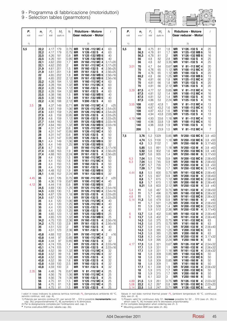
P1 n2 P2 M2 fs Riduttore - Motore i kW min-1 kW daN m Gear reducer - Motor
1) 2)
P1 n2 P2 M2 fs Riduttore - Motore i kW min-1 kW daN m Gear reducer - Motor
1) 2)
45A04 December 2011
9 - Programma di fabbricazione (motoriduttori)9 - Selection tables (gearmotors)
P1 n2 P2 M2 fs Riduttore - Motore i kW min-1 kW daN m Gear reducer - Motor
1) 2)
I valori in rosso indicano la potenza termica nominale PtN (temperatura ambiente 40 °C, servizio continuo, ved. cap. 4).1) Potenze per servizio continuo S1; per servizi S2 ... S10 è possibile incrementarle (ved.
cap. 2b); proporzionalmente P2, M2 aumentano e fs diminuisce.2) Per la designazione completa per l’ordinazione ved. cap. 3.* Forma costruttiva B5R (ved. tabella cap. 2b).
Values in red state nominal thermal power PtN (ambient temperature 40 °C, continuous duty, see ch. 4).1) Powers valid for continuous duty S1; increase possible for S2 ... S10 (see ch. 2b) in
which case P2, M2 increase and fs decreases proportionately.2) For complete designation when ordering see ch. 3.* Mounting position B5R (see table ch. 2b).
5,5 22,2 4,17 179 0,75 MR V 126 - 112 MC 4 63 22,2 4,17 179 0,75 MR V 126 - 132 S 4 63 22,5 4,26 181 0,8 MR V 125 - 132 MB 6 40 22,5 4,26 181 0,95 MR V 126 - 132 MB 6 40 22,1 4,62 200 1,7 MR IV 160 - 112 MC 4 23,17 x 20 22,1 4,62 200 2 MR IV 161 - 112 MC 4 23,17 x 20 21,9 4,61 201 1,5 MR IV 160 - 132 S 4 22,56 x 25 21,9 4,61 201 1,8 MR IV 161 - 132 S 4 22,56 x 25 22 4,65 202 1,8 MR IV 160 - 132 MB 6 22,56 x 16 22 4,65 202 2,12 MR IV 161 - 132 MB 6 22,56 x 16 22,2 4,28 184 1,12 MR V 160 - 112 MC 4 63 22,2 4,28 184 1,32 MR V 161 - 112 MC 4 63 22,2 4,28 184 1,12 MR V 160 - 132 S 4 63 22,2 4,28 184 1,32 MR V 161 - 132 S 4 63 22,5 4,38 186 1,5 MR V 160 - 132 MB 6 40 22,5 4,38 186 1,8 MR V 161 - 132 MB 6 40 22,2 4,36 188 2,12 MR V 200 - 132 S 4 63 3,5 28 4,37 149 0,71 MR IV 100 - 112 MC 4 22 x 25 27,6 4,61 159 1,06 MR IV 125 - 112 MC 4 22,54 x 20 27,6 4,61 159 1,25 MR IV 126 - 112 MC 4 22,54 x 20 27,6 4,6 159 0,95 MR IV 125 - 132 S 4 22,03 x 25 27,6 4,6 159 1,12 MR IV 126 - 132 S 4 22,03 x 25 27,7 4,64 160 1,12 MR IV 125 - 132 MB 6 22,03 x 16 27,7 4,64 160 1,32 MR IV 126 - 132 MB 6 22,03 x 16 28 4,31 147 0,8 MR V 125 - 112 MC 4 50 28 4,31 147 0,95 MR V 126 - 112 MC 4 50 28 4,31 147 0,8 MR V 125 - 132 S 4 50 28 4,31 147 0,95 MR V 126 - 132 S 4 50 28,1 4,4 149 1,06 MR V 125 - 132 MB 6 32 28,1 4,4 149 1,25 MR V 126 - 132 MB 6 32 27,6 4,7 163 2 MR IV 160 - 112 MC 4 23,17 x 16 27,4 4,68 163 1,9 MR IV 160 - 132 S 4 22,56 x 20 27,4 4,68 163 2,24 MR IV 161 - 132 S 4 22,56 x 20 28 4,4 150 1,5 MR V 160 - 112 MC 4 50 28 4,4 150 1,8 MR V 161 - 112 MC 4 50 28 4,4 150 1,5 MR V 160 - 132 S 4 50 28 4,4 150 1,8 MR V 161 - 132 S 4 50 28,1 4,48 152 1,9 MR V 160 - 132 MB 6 32 28,1 4,48 152 2,24 MR V 161 - 132 MB 6 32 4,45 35 4,61 126 0,75 MR IV 100 - 112 MC 4 22 x 20 35 4,36 119 0,67 MR V 100 - 112 MC 4 40 4,12 36 4,44 118 0,8 MR V 100 - 132 MB 6 25 34,5 4,69 130 1,25 MR IV 125 - 112 MC 4 22,54 x 16 34,5 4,69 130 1,5 MR IV 126 - 112 MC 4 22,54 x 16 34,5 4,67 129 1,18 MR IV 125 - 132 S 4 22,03 x 20 34,5 4,67 129 1,4 MR IV 126 - 132 S 4 22,03 x 20 35 4,4 120 1,06 MR V 125 - 112 MC 4 40 35 4,4 120 1,25 MR V 126 - 112 MC 4 40 35 4,4 120 1,06 MR V 125 - 132 S 4 40 35 4,4 120 1,25 MR V 126 - 132 S 4 40 36 4,65 123 1,12 MR V 125 - 132 MB 6 25 36 4,65 123 1,32 MR V 126 - 132 MB 6 25 34,2 4,75 133 2,36 MR IV 160 - 132 S 4 22,56 x 16 34,2 4,75 133 2,8 MR IV 161 - 132 S 4 22,56 x 16 35 4,51 123 2 MR V 160 - 132 S 4 40 35 4,51 123 2,36 MR V 161 - 132 S 4 40 43,8 4,68 102 0,9 MR IV 100 - 112 MC 4 22 x 16 43,8 4,44 97 0,85 MR V 100 - 112 MC 4 32 43,8 4,44 97 0,85 MR V 100 - 132 S 4 32 43,1 4,74 105 1,4 MR IV 125 - 132 S 4 22,03 x 16 43,1 4,74 105 1,7 MR IV 126 - 132 S 4 22,03 x 16 43,8 4,52 99 1,32 MR V 125 - 112 MC 4 32 43,8 4,52 99 1,6 MR V 126 - 112 MC 4 32 43,8 4,52 99 1,32 MR V 125 - 132 S 4 32 43,8 4,52 99 1,6 MR V 126 - 132 S 4 32 43,8 4,59 100 2,5 MR V 160 - 132 S 4 32 43,8 4,59 100 3 MR V 161 - 132 S 4 32 2,35 56 4,48 76 0,67 MR V 81 - 112 MC 4 25 56 4,56 78 1,06 MR V 100 - 112 MC 4 25 56 4,56 78 1,06 MR V 100 - 132 S 4 25 56 4,75 81 1,5 MR V 125 - 112 MC 4 25 56 4,75 81 1,8 MR V 126 - 112 MC 4 25 56 4,75 81 1,5 MR V 125 - 132 S 4 25
P1 n2 P2 M2 fs Riduttore - Motore i kW min-1 kW daN m Gear reducer - Motor
1) 2)
5,5 56 4,75 81 1,8 MR V 126 - 132 S 4 25 56,3 4,78 81 1,7 MR V 125 - 132 MB 6 16 56,3 4,78 81 2 MR V 126 - 132 MB 6 16 56 4,8 82 2,8 MR V 160 - 132 S 4 25 56 4,8 82 3,35 MR V 161 - 132 S 4 25 3,01 70 4,7 64 0,67 MR V 81 - 112 MC 4 20 70 4,76 65 1,12 MR V 100 - 112 MC 4 20 70 4,76 65 1,12 MR V 100 - 132 S 4 20 69,2 4,8 66 1,25 MR V 100 - 132 MB 6 13 70 4,81 66 1,8 MR V 125 - 112 MC 4 20 70 4,81 66 1,8 MR V 125 - 132 S 4 20 70 4,81 66 2,12 MR V 126 - 132 S 4 20 3,29 87,5 4,77 52 0,85 MR V 81 - 112 MC 4 16 87,5 4,81 52 1,4 MR V 100 - 112 MC 4 16 87,5 4,81 52 1,4 MR V 100 - 132 S 4 16 87,5 4,86 53 2,24 MR V 125 - 132 S 4 16 3,55 108 4,82 42,8 1 MR V 81 - 112 MC 4 13 108 4,87 43,2 1,6 MR V 100 - 112 MC 4 13 108 4,87 43,2 1,6 MR V 100 - 132 S 4 13 108 4,94 43,8 2,65 MR V 125 - 132 S 4 13 4,19 140 4,93 33,6 1,18 MR V 81 - 112 MC 4 10 140 4,96 33,8 1,9 MR V 100 - 112 MC 4 10 140 4,96 33,8 1,9 MR V 100 - 132 S 4 10 200 5 23,9 1,5 MR V 81 - 112 MC 4 7
7,5 3,76 5,2 1329 0,85 MR IV 250 - 132 MC 6 23,8 x 63 4,74 5,5 1100 1,18 MR IV 250 - 132 MC 6 23,8 x 50 4,5 5,3 1132 1 MR IV 250 - 160 M 6 23,17 x 63 5,85 5,5 891 1,18 MR IV 250 - 132 M 4 23,8 x 63 5,92 5,6 902 1,6 MR IV 250 - 132 MC 6 23,8 x 40 5,67 5,6 935 1,4 MR IV 250 - 160 M 6 23,17 x 50 6,3 7,04 5,5 745 0,9 MR IV 200 - 132 MC 6 22,56 x 50 6,3 7,04 5,5 745 0,9 MR IV 200 - 160 M 6 22,56 x 50 7,37 5,7 735 1,7 MR IV 250 - 132 M 4 23,8 x 50 7,09 5,7 768 1,7 MR IV 250 - 132 MC 6 23,17 x 40 4,44 8,8 5,5 600 0,75 MR IV 161 - 132 MC 6 22,56 x 40 8,7 5,5 607 0,9 MR IV 200 - 132 M 4 22,56 x 63 8,8 5,7 615 1,12 MR IV 200 - 132 MC 6 22,56 x 40 8,8 5,7 615 1,12 MR IV 200 - 160 M 6 22,56 x 40 9,21 5,8 603 2,12 MR IV 250 - 132 M 4 23,8 x 40 5,4 11 5,6 487 0,75 MR IV 161 - 132 M 4 22,56 x 50 4,8 11 5,7 496 0,75 MR IV 160 - 132 MC 6 22,56 x 32 4,8 11 5,7 493 0,9 MR IV 161 - 132 MC 6 22,56 x 32 5,14 11,3 5,6 479 0,9 MR IV 161 - 160 M 6 22 x 40 11 5,7 501 1,25 MR IV 200 - 132 M 4 22,56 x 50 11 5,9 508 1,4 MR IV 200 - 132 MC 6 22,56 x 32 11 5,9 512 2,36 MR IV 250 - 132 M 4 23,17 x 40 6 13,7 5,8 402 0,85 MR IV 160 - 132 M 4 22,56 x 40 6 13,7 5,8 402 1 MR IV 161 - 132 M 4 22,56 x 40 14,3 5,6 375 0,75 MR V 161 - 132 MC 6 63 14,3 5,6 375 0,75 MR V 161 - 160 M 6 63 13,7 5,9 410 1,5 MR IV 200 - 132 M 4 22,56 x 40 14,3 5,8 385 1,25 MR V 200 - 132 MC 6 63 14,3 5,8 385 1,25 MR V 200 - 160 M 6 63 13,8 6,3 434 2,36 MR IV 250 - 132 M 4 23,17 x 32 14,3 5,9 395 2,24 MR V 250 - 160 M 6 63 4,17 17,3 5,8 321 0,67 MR IV 126 - 132 M* 4 22,54 x 32 17,1 5,9 331 1 MR IV 160 - 132 M 4 22,56 x 32 17,1 5,9 331 1,18 MR IV 161 - 132 M 4 22,56 x 32 18 5,8 309 0,85 MR V 160 - 132 MC 6 50 18 5,8 309 1 MR V 161 - 132 MC 6 50 18 5,8 309 0,85 MR V 160 - 160 M 6 50 18 5,8 309 1 MR V 161 - 160 M 6 50 17,1 6,1 338 1,9 MR IV 200 - 132 M 4 22,56 x 32 18 5,9 315 1,7 MR V 200 - 132 MC 6 50 18 5,9 315 1,7 MR V 200 - 160 M 6 50 18 6,1 322 3 MR V 250 - 160 M 6 50 4,89 21,5 5,9 261 0,75 MR IV 126 - 132 M 4 22,03 x 32 5,06 22,2 6,2 267 0,8 MR IV 126 - 132 MC 6 22,03 x 20 5,14 22,5 5,8 247 0,71 MR V 126 - 132 MC 6 40
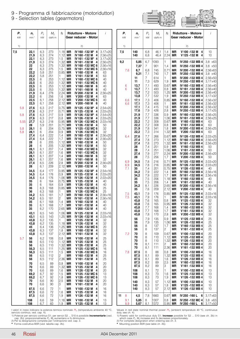
P1 n2 P2 M2 fs Riduttore - Motore i kW min-1 kW daN m Gear reducer - Motor
1) 2)
P1 n2 P2 M2 fs Riduttore - Motore i kW min-1 kW daN m Gear reducer - Motor
1) 2)
46 A04 December 2011
9 - Programma di fabbricazione (motoriduttori)9 - Selection tables (gearmotors)
P1 n2 P2 M2 fs Riduttore - Motore i kW min-1 kW daN m Gear reducer - Motor
1) 2)
I valori in rosso indicano la potenza termica nominale PtN (temperatura ambiente 40 °C, servizio continuo, ved. cap. 4).1) Potenze per servizio continuo S1; per servizi S2 ... S10 è possibile incrementarle (ved.
cap. 2b); proporzionalmente P2, M2 aumentano e fs diminuisce.2) Per la designazione completa per l’ordinazione ved. cap. 3.* Forma costruttiva B5R (ved. tabella cap. 2b).
Values in red state nominal thermal power PtN (ambient temperature 40 °C, continuous duty, see ch. 4).1) Powers valid for continuous duty S1; increase possible for S2 ... S10 (see ch. 2b) in
which case P2, M2 increase and fs decreases proportionately.2) For complete designation when ordering see ch. 3.* Mounting position B5R (see table ch. 2b).
7,5 22,1 6,3 273 1,18 MR IV 160 - 132 M* 4 23,17 x 20 21,9 6,3 274 1,12 MR IV 160 - 132 M 4 22,56 x 25 22,1 6,3 273 1,5 MR IV 161 - 132 M* 4 23,17 x 20 21,9 6,3 274 1,32 MR IV 161 - 132 M 4 22,56 x 25 22 6,3 275 1,32 MR IV 160 - 132 MC 6 22,56 x 16 22 6,3 275 1,5 MR IV 161 - 132 MC 6 22,56 x 16 22,2 5,8 251 0,85 MR V 160 - 132 M 4 63 22,2 5,8 251 1 MR V 161 - 132 M 4 63 22,5 6 253 1,12 MR V 160 - 132 MC 6 40 22,5 6 253 1,32 MR V 161 - 132 MC 6 40 22,5 6 253 1,12 MR V 160 - 160 M 6 40 22,5 6 253 1,32 MR V 161 - 160 M 6 40 21,9 6,4 278 2,24 MR IV 200 - 132 M 4 22,56 x 25 22,2 6 256 1,6 MR V 200 - 132 M 4 63 22,5 6,1 258 2,12 MR V 200 - 132 MC 6 40 22,5 6,1 258 2,12 MR V 200 - 160 M 6 40 5,8 27,6 6,3 217 0,75 MR IV 125 - 132 M* 4 22,54 x 20 27,6 6,3 217 0,71 MR IV 125 - 132 M 4 22,03 x 25 5,8 27,6 6,3 217 0,9 MR IV 126 - 132 M* 4 22,54 x 20 27,6 6,3 217 0,8 MR IV 126 - 132 M 4 22,03 x 25 5,55 27,7 6,3 218 0,95 MR IV 126 - 132 MC 6 22,03 x 16 28 5,9 201 0,71 MR V 126 - 132 M 4 50 5,8 28,1 6 204 0,75 MR V 125 - 132 MC 6 32 5,8 28,1 6 204 0,9 MR V 126 - 132 MC 6 32 27,4 6,4 222 1,4 MR IV 160 - 132 M 4 22,56 x 20 27,4 6,4 222 1,7 MR IV 161 - 132 M 4 22,56 x 20 28 6 205 1,12 MR V 160 - 132 M 4 50 28 6 205 1,32 MR V 161 - 132 M 4 50 28,1 6,1 207 1,4 MR V 160 - 132 MC 6 32 28,1 6,1 207 1,6 MR V 161 - 132 MC 6 32 28,1 6,1 207 1,4 MR V 160 - 160 M 6 32 28,1 6,1 207 1,6 MR V 161 - 160 M 6 32 27,4 6,5 226 2,8 MR IV 200 - 132 M 4 22,56 x 20 28 6,1 209 2,12 MR V 200 - 132 M 4 50 34,5 6,4 177 0,95 MR IV 125 - 132 M* 4 22,54 x 16 34,5 6,4 176 0,9 MR IV 125 - 132 M 4 22,03 x 20 34,5 6,4 176 1,06 MR IV 126 - 132 M 4 22,03 x 20 35 6 164 0,75 MR V 125 - 132 M 4 40 35 6 164 0,9 MR V 126 - 132 M 4 40 36 6,3 168 0,85 MR V 125 - 132 MC 6 25 36 6,3 168 1 MR V 126 - 132 MC 6 25 34,2 6,5 181 1,7 MR IV 160 - 132 M 4 22,56 x 16 34,2 6,5 181 2 MR IV 161 - 132 M 4 22,56 x 16 35 6,1 168 1,4 MR V 160 - 132 M 4 40 35 6,1 168 1,7 MR V 161 - 132 M 4 40 35 6,2 170 2,65 MR V 200 - 132 M 4 40 43,1 6,5 143 1,06 MR IV 125 - 132 M 4 22,03 x 16 43,1 6,5 143 1,25 MR IV 126 - 132 M 4 22,03 x 16 43,8 6,2 135 1 MR V 125 - 132 M 4 32 43,8 6,2 135 1,18 MR V 126 - 132 M 4 32 45 6,4 136 1,25 MR V 126 - 132 MC 6 20 43,8 6,3 137 1,8 MR V 160 - 132 M 4 32 43,8 6,3 137 2,12 MR V 161 - 132 M 4 32 5,7 56 6,2 106 0,8 MR V 100 - 132 M 4 25 56 6,5 110 1,12 MR V 125 - 132 M 4 25 56 6,5 110 1,32 MR V 126 - 132 M 4 25 56,3 6,5 111 1,25 MR V 125 - 132 MC 6 16 56,3 6,5 111 1,5 MR V 126 - 132 MC 6 16 56 6,5 112 2 MR V 160 - 132 M 4 25 56 6,5 112 2,36 MR V 161 - 132 M 4 25 70 6,5 89 0,8 MR V 100 - 132 M 4 20 70 6,6 89 1,32 MR V 125 - 132 M 4 20 70 6,6 89 1,6 MR V 126 - 132 M 4 20 69,2 6,7 92 1,5 MR V 125 - 132 MC 6 13 69,2 6,7 92 1,8 MR V 126 - 132 MC 6 13 70 6,6 90 2,5 MR V 160 - 132 M 4 20 70 6,6 90 3 MR V 161 - 132 M 4 20 87,5 6,6 72 1 MR V 100 - 132 M 4 16 87,5 6,6 72 1,6 MR V 125 - 132 M 4 16 87,5 6,6 72 1,9 MR V 126 - 132 M 4 16 108 6,6 59 1,18 MR V 100 - 132 M 4 13 108 6,7 60 1,9 MR V 125 - 132 M 4 13
P1 n2 P2 M2 fs Riduttore - Motore i kW min-1 kW daN m Gear reducer - Motor
1) 2)
7,5 140 6,8 46,1 1,4 MR V 100 - 132 M 4 10 140 6,8 46,4 2,24 MR V 125 - 132 M 4 10
9,2 5,85 6,7 1093 1 MR IV 250 - 132 MB 4 23,8 x 63 7,37 7 901 1,4 MR IV 250 - 132 MB 4 23,8 x 50 7,6 8,7 6,8 745 0,71 MR IV 200 - 132 MB 4 22,56 x 63 9,21 7,1 740 1,7 MR IV 250 - 132 MB 4 23,8 x 40 11 7 614 1 MR IV 200 - 132 MB 4 22,56 x 50 11 7,3 629 1,9 MR IV 250 - 132 MB 4 23,17 x 40 6 13,7 7,1 493 0,67 MR IV 160 - 132 MB 4 22,56 x 40 6 13,7 7,1 493 0,8 MR IV 161 - 132 MB 4 22,56 x 40 13,7 7,2 503 1,25 MR IV 200 - 132 MB 4 22,56 x 40 13,8 7,7 532 1,9 MR IV 250 - 132 MB 4 23,17 x 32 6,6 17,1 7,3 406 0,85 MR IV 160 - 132 MB 4 22,56 x 32 6,6 17,1 7,3 406 1 MR IV 161 - 132 MB 4 22,56 x 32 17,1 7,4 415 1,6 MR IV 200 - 132 MB 4 22,56 x 32 17,6 7,9 426 2,8 MR IV 250 - 132 MB 4 23,17 x 25 21,9 7,7 336 0,9 MR IV 160 - 132 MB 4 22,56 x 25 21,9 7,7 336 1,06 MR IV 161 - 132 MB 4 22,56 x 25 22,2 7,2 308 0,67 MR V 160 - 132 MB 4 63 22,2 7,2 308 0,8 MR V 161 - 132 MB 4 63 21,9 7,8 341 1,8 MR IV 200 - 132 MB 4 22,56 x 25 22,2 7,3 314 1,32 MR V 200 - 132 MB 4 63 6,4 27,6 7,7 266 0,67 MR IV 126 - 132 MB 4 22,03 x 25 27,4 7,8 273 1,12 MR IV 160 - 132 MB 4 22,56 x 20 27,4 7,8 273 1,32 MR IV 161 - 132 MB 4 22,56 x 20 28 7,4 251 0,9 MR V 160 - 132 MB 4 50 28 7,4 251 1,06 MR V 161 - 132 MB 4 50 27,4 7,9 277 2,24 MR IV 200 - 132 MB 4 22,56 x 20 28 7,5 256 1,7 MR V 200 - 132 MB 4 50 6,9 34,5 7,8 216 0,71 MR IV 125 - 132 MB 4 22,03 x 20 6,9 34,5 7,8 216 0,85 MR IV 126 - 132 MB 4 22,03 x 20 7,1 35 7,4 201 0,75 MR V 126 - 132 MB 4 40 34,2 7,9 222 1,4 MR IV 160 - 132 MB 4 22,56 x 16 34,2 7,9 222 1,7 MR IV 161 - 132 MB 4 22,56 x 16 35 7,5 206 1,18 MR V 160 - 132 MB 4 40 35 7,5 206 1,4 MR V 161 - 132 MB 4 40 34,2 8,1 226 2,65 MR IV 200 - 132 MB 4 22,56 x 16 35 7,6 209 2,12 MR V 200 - 132 MB 4 40 7,5 43,1 7,9 176 0,85 MR IV 125 - 132 MB 4 22,03 x 16 7,5 43,1 7,9 176 1 MR IV 126 - 132 MB 4 22,03 x 16 43,8 7,6 165 0,8 MR V 125 - 132 MB 4 32 43,8 7,6 165 0,95 MR V 126 - 132 MB 4 32 43,8 7,7 168 1,4 MR V 160 - 132 MB 4 32 43,8 7,7 168 1,7 MR V 161 - 132 MB 4 32 43,8 7,8 170 2,8 MR V 200 - 132 MB 4 32 56 7,9 135 0,9 MR V 125 - 132 MB 4 25 56 7,9 135 1,06 MR V 126 - 132 MB 4 25 56 8 137 1,7 MR V 160 - 132 MB 4 25 56 8 137 2 MR V 161 - 132 MB 4 25 7,2 70 8 109 0,67 MR V 100 - 132 MB 4 20 70 8 110 1,12 MR V 125 - 132 MB 4 20 70 8 110 1,32 MR V 126 - 132 MB 4 20 70 8,1 111 2 MR V 160 - 132 MB 4 20 70 8,1 111 2,36 MR V 161 - 132 MB 4 20 7,8 87,5 8 88 0,8 MR V 100 - 132 MB 4 16 87,5 8,1 89 1,32 MR V 125 - 132 MB 4 16 87,5 8,1 89 1,6 MR V 126 - 132 MB 4 16 87,5 8,2 89 2,5 MR V 160 - 132 MB 4 16 87,5 8,2 89 3 MR V 161 - 132 MB 4 16 108 8,1 72 1 MR V 100 - 132 MB 4 13 108 8,3 73 1,6 MR V 125 - 132 MB 4 13 108 8,3 73 1,9 MR V 126 - 132 MB 4 13 140 8,3 57 1,12 MR V 100 - 132 MB 4 10 140 8,3 57 1,8 MR V 125 - 132 MB 4 10 140 8,3 57 2,12 MR V 126 - 132 MB 4 10
11 8 4,5 7,8 1660 0,67 MR IV 250 - 160 L 6 23,17 x 63 9,1 5,85 8 1307 0,8 MR IV 250 - 132 MC 4 23,8 x 63 8,9 5,67 8,1 1372 0,95 MR IV 250 - 160 L 6 23,17 x 50
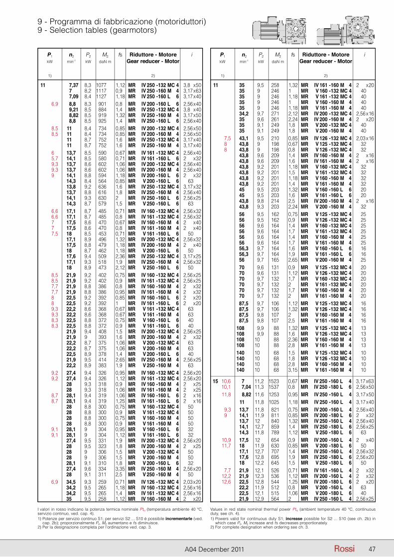
P1 n2 P2 M2 fs Riduttore - Motore i kW min-1 kW daN m Gear reducer - Motor
1) 2)
P1 n2 P2 M2 fs Riduttore - Motore i kW min-1 kW daN m Gear reducer - Motor
1) 2)
47A04 December 2011
9 - Programma di fabbricazione (motoriduttori)9 - Selection tables (gearmotors)
P1 n2 P2 M2 fs Riduttore - Motore i kW min-1 kW daN m Gear reducer - Motor
1) 2)
I valori in rosso indicano la potenza termica nominale PtN (temperatura ambiente 40 °C, servizio continuo, ved. cap. 4).1) Potenze per servizio continuo S1; per servizi S2 ... S10 è possibile incrementarle (ved.
cap. 2b); proporzionalmente P2, M2 aumentano e fs diminuisce.2) Per la designazione completa per l’ordinazione ved. cap. 3.
Values in red state nominal thermal power PtN (ambient temperature 40 °C, continuous duty, see ch. 4).1) Powers valid for continuous duty S1; increase possible for S2 ... S10 (see ch. 2b) in
which case P2, M2 increase and fs decreases proportionately.2) For complete designation when ordering see ch. 3.
11 7,37 8,3 1077 1,12 MR IV 250 - 132 MC 4 23,8 x 50 7 8,2 1117 0,9 MR IV 250 - 160 M 4 23,17 x 63 7,09 8,4 1127 1,18 MR IV 250 - 160 L 6 23,17 x 40 6,9 8,8 8,3 901 0,8 MR IV 200 - 160 L 6 22,56 x 40 9,21 8,5 884 1,4 MR IV 250 - 132 MC 4 23,8 x 40 8,82 8,5 919 1,32 MR IV 250 - 160 M 4 23,17 x 50 8,8 8,5 925 1,4 MR IV 250 - 160 L 6 22,56 x 40 8,5 11 8,4 734 0,85 MR IV 200 - 132 MC 4 22,56 x 50 8,5 11 8,4 734 0,85 MR IV 200 - 160 M 4 22,56 x 50 11 8,7 752 1,6 MR IV 250 - 132 MC 4 23,17 x 40 11 8,7 752 1,6 MR IV 250 - 160 M 4 23,17 x 40 6 13,7 8,5 590 0,67 MR IV 161 - 132 MC 4 22,56 x 40 5,7 14,1 8,5 580 0,71 MR IV 161 - 160 L 6 22 x 32 9,3 13,7 8,6 602 1,06 MR IV 200 - 132 MC 4 22,56 x 40 9,3 13,7 8,6 602 1,06 MR IV 200 - 160 M 4 22,56 x 40 9 14,1 8,8 594 1,18 MR IV 200 - 160 L 6 22 x 32 14,3 8,4 564 0,85 MR V 200 - 160 L 6 63 13,8 9,2 636 1,6 MR IV 250 - 132 MC 4 23,17 x 32 13,7 8,8 616 1,8 MR IV 250 - 160 M 4 22,56 x 40 14,1 9,3 630 2 MR IV 250 - 160 L 6 22,56 x 25 14,3 8,7 579 1,5 MR V 250 - 160 L 6 63 6,6 17,1 8,7 485 0,71 MR IV 160 - 132 MC 4 22,56 x 32 6,6 17,1 8,7 485 0,8 MR IV 161 - 132 MC 4 22,56 x 32 7 17,5 8,6 470 0,67 MR IV 160 - 160 M 4 22 x 40 7 17,5 8,6 470 0,8 MR IV 161 - 160 M 4 22 x 40 7,5 18 8,5 453 0,71 MR V 161 - 160 L 6 50 17,1 8,9 496 1,32 MR IV 200 - 132 MC 4 22,56 x 32 17,5 8,8 479 1,18 MR IV 200 - 160 M 4 22 x 40 18 8,7 462 1,18 MR V 200 - 160 L 6 50 17,6 9,4 509 2,36 MR IV 250 - 132 MC 4 23,17 x 25 17,1 9,3 518 1,9 MR IV 250 - 160 M 4 22,56 x 32 18 8,9 473 2,12 MR V 250 - 160 L 6 50 8,5 21,9 9,2 402 0,75 MR IV 160 - 132 MC 4 22,56 x 25 8,5 21,9 9,2 402 0,9 MR IV 161 - 132 MC 4 22,56 x 25 7,7 21,9 8,8 386 0,8 MR IV 160 - 160 M 4 22 x 32 7,7 21,9 8,8 386 0,95 MR IV 161 - 160 M 4 22 x 32 8 22,5 9,2 392 0,85 MR IV 160 - 160 L 6 22 x 20 8 22,5 9,2 392 1 MR IV 161 - 160 L 6 22 x 20 9,3 22,2 8,6 368 0,67 MR V 161 - 132 MC 4 63 9,3 22,2 8,6 368 0,67 MR V 161 - 160 M 4 63 8,3 22,5 8,8 372 0,75 MR V 160 - 160 L 6 40 8,3 22,5 8,8 372 0,9 MR V 161 - 160 L 6 40 21,9 9,4 408 1,5 MR IV 200 - 132 MC 4 22,56 x 25 21,9 9 393 1,6 MR IV 200 - 160 M 4 22 x 32 22,2 8,7 375 1,06 MR V 200 - 132 MC 4 63 22,2 8,7 375 1,06 MR V 200 - 160 M 4 63 22,5 8,9 378 1,4 MR V 200 - 160 L 6 40 21,9 9,5 414 2,65 MR IV 250 - 160 M 4 22,56 x 25 22,2 8,9 383 1,9 MR V 250 - 160 M 4 63 9,2 27,4 9,4 326 0,95 MR IV 160 - 132 MC 4 22,56 x 20 9,2 27,4 9,4 326 1,12 MR IV 161 - 132 MC 4 22,56 x 20 28 9,3 318 0,9 MR IV 160 - 160 M 4 22 x 25 28 9,3 318 1,06 MR IV 161 - 160 M 4 22 x 25 8,7 28,1 9,4 319 1,06 MR IV 160 - 160 L 6 22 x 16 8,7 28,1 9,4 319 1,25 MR IV 161 - 160 L 6 22 x 16 28 8,8 300 0,75 MR V 160 - 132 MC 4 50 28 8,8 300 0,9 MR V 161 - 132 MC 4 50 28 8,8 300 0,75 MR V 160 - 160 M 4 50 28 8,8 300 0,9 MR V 161 - 160 M 4 50 9,1 28,1 9 304 0,95 MR V 160 - 160 L 6 32 9,1 28,1 9 304 1,12 MR V 161 - 160 L 6 32 27,4 9,5 331 1,9 MR IV 200 - 132 MC 4 22,56 x 20 28 9,5 323 1,8 MR IV 200 - 160 M 4 22 x 25 28 9 306 1,5 MR V 200 - 132 MC 4 50 28 9 306 1,5 MR V 200 - 160 M 4 50 28,1 9,1 310 1,8 MR V 200 - 160 L 6 32 27,4 9,6 334 3,35 MR IV 250 - 160 M 4 22,56 x 20 28 9,1 311 2,5 MR V 250 - 160 M 4 50 6,9 34,5 9,3 259 0,71 MR IV 126 - 132 MC 4 22,03 x 20 34,2 9,5 265 1,18 MR IV 160 - 132 MC 4 22,56 x 16 34,2 9,5 265 1,4 MR IV 161 - 132 MC 4 22,56 x 16 35 9,5 258 1,12 MR IV 160 - 160 M 4 22 x 20
P1 n2 P2 M2 fs Riduttore - Motore i kW min-1 kW daN m Gear reducer - Motor
1) 2)
11 35 9,5 258 1,32 MR IV 161 - 160 M 4 22 x 20 35 9 246 1 MR V 160 - 132 MC 4 40 35 9 246 1,18 MR V 161 - 132 MC 4 40 35 9 246 1 MR V 160 - 160 M 4 40 35 9 246 1,18 MR V 161 - 160 M 4 40 34,2 9,7 271 2,12 MR IV 200 - 132 MC 4 22,56 x 16 35 9,6 261 2,24 MR IV 200 - 160 M 4 22 x 20 35 9,1 249 1,8 MR V 200 - 132 MC 4 40 35 9,1 249 1,8 MR V 200 - 160 M 4 40 7,5 43,1 9,5 210 0,85 MR IV 126 - 132 MC 4 22,03 x 16 8 43,8 9 198 0,67 MR V 125 - 132 MC 4 32 8 43,8 9 198 0,8 MR V 126 - 132 MC 4 32 43,8 9,6 209 1,4 MR IV 160 - 160 M 4 22 x 16 43,8 9,6 209 1,6 MR IV 161 - 160 M 4 22 x 16 43,8 9,2 201 1,18 MR V 160 - 132 MC 4 32 43,8 9,2 201 1,5 MR V 161 - 132 MC 4 32 43,8 9,2 201 1,18 MR V 160 - 160 M 4 32 43,8 9,2 201 1,4 MR V 161 - 160 M 4 32 45 9,5 203 1,32 MR V 160 - 160 L 6 20 45 9,5 203 1,6 MR V 161 - 160 L 6 20 43,8 9,8 214 2,5 MR IV 200 - 160 M 4 22 x 16 43,8 9,3 203 2,24 MR V 200 - 160 M 4 32 56 9,5 162 0,75 MR V 125 - 132 MC 4 25 56 9,5 162 0,9 MR V 126 - 132 MC 4 25 56 9,6 164 1,4 MR V 160 - 132 MC 4 25 56 9,6 164 1,7 MR V 161 - 132 MC 4 25 56 9,6 164 1,4 MR V 160 - 160 M 4 25 56 9,6 164 1,7 MR V 161 - 160 M 4 25 56,3 9,7 164 1,6 MR V 160 - 160 L 6 16 56,3 9,7 164 1,9 MR V 161 - 160 L 6 16 56 9,7 165 2,65 MR V 200 - 160 M 4 25 70 9,6 131 0,9 MR V 125 - 132 MC 4 20 70 9,6 131 1,12 MR V 126 - 132 MC 4 20 70 9,7 132 1,7 MR V 160 - 132 MC 4 20 70 9,7 132 2 MR V 161 - 132 MC 4 20 70 9,7 132 1,7 MR V 160 - 160 M 4 20 70 9,7 132 2 MR V 161 - 160 M 4 20 87,5 9,7 106 1,12 MR V 125 - 132 MC 4 16 87,5 9,7 106 1,32 MR V 126 - 132 MC 4 16 87,5 9,8 107 2 MR V 160 - 160 M 4 16 87,5 9,8 107 2,5 MR V 161 - 160 M 4 16 108 9,9 88 1,32 MR V 125 - 132 MC 4 13 108 9,9 88 1,6 MR V 126 - 132 MC 4 13 108 10 88 2,36 MR V 160 - 160 M 4 13 108 10 88 2,8 MR V 161 - 160 M 4 13 140 10 68 1,5 MR V 125 - 132 MC 4 10 140 10 68 1,8 MR V 126 - 132 MC 4 10 140 10 68 2,8 MR V 160 - 160 M 4 10 140 10 68 3,15 MR V 161 - 160 M 4 10
15 10,6 7 11,2 1523 0,67 MR IV 250 - 160 L 4 23,17 x 63 10,1 7,04 11,3 1537 0,8 MR IV 250 - 180 L 6 22,56 x 50 11,8 8,82 11,6 1253 0,95 MR IV 250 - 160 L 4 23,17 x 50 11 11,8 1025 1,18 MR IV 250 - 160 L 4 23,17 x 40 9,3 13,7 11,8 821 0,75 MR IV 200 - 160 L 4 22,56 x 40 9 14,1 11,9 811 0,85 MR IV 200 - 180 L 6 22 x 32 13,7 12 840 1,32 MR IV 250 - 160 L 4 22,56 x 40 14,1 12,7 859 1,4 MR IV 250 - 180 L 6 22,56 x 25 14,3 11,8 789 1,12 MR V 250 - 180 L 6 63 10,9 17,5 12 654 0,9 MR IV 200 - 160 L 4 22 x 40 11,7 18 11,9 630 0,85 MR V 200 - 180 L 6 50 17,1 12,7 707 1,4 MR IV 250 - 160 L 4 22,56 x 32 17,6 12,8 695 1,9 MR IV 250 - 180 L 6 22,56 x 20 18 12,2 645 1,5 MR V 250 - 180 L 6 50 7,7 21,9 12,1 526 0,71 MR IV 161 - 160 L 4 22 x 32 12,2 21,9 12,3 536 1,12 MR IV 200 - 160 L 4 22 x 32 12,6 22,5 12,8 544 1,25 MR IV 200 - 180 L 6 22 x 20 22,2 11,9 512 0,8 MR V 200 - 160 L 4 63 22,5 12,1 515 1,06 MR V 200 - 180 L 6 40 21,9 12,9 564 2 MR IV 250 - 160 L 4 22,56 x 25
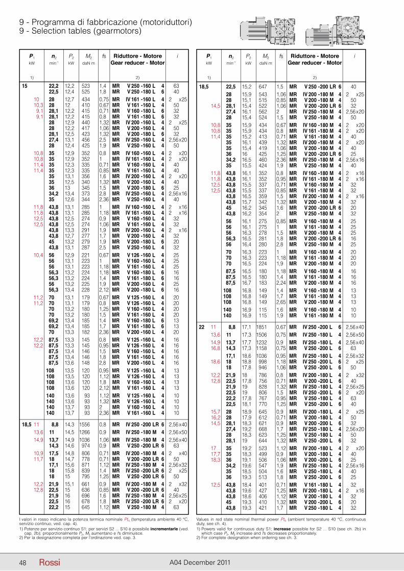
P1 n2 P2 M2 fs Riduttore - Motore i kW min-1 kW daN m Gear reducer - Motor
1) 2)
P1 n2 P2 M2 fs Riduttore - Motore i kW min-1 kW daN m Gear reducer - Motor
1) 2)
48 A04 December 2011
9 - Programma di fabbricazione (motoriduttori)9 - Selection tables (gearmotors)
P1 n2 P2 M2 fs Riduttore - Motore i kW min-1 kW daN m Gear reducer - Motor
1) 2)
P1 n2 P2 M2 fs Riduttore - Motore i kW min-1 kW daN m Gear reducer - Motor
1) 2) 15 22,2 12,2 523 1,4 MR V 250 - 160 L 4 63 22,5 12,4 525 1,8 MR V 250 - 180 L 6 40 10 28 12,7 434 0,75 MR IV 161 - 160 L 4 12 x 25 10,3 28 12 410 0,67 MR V 161 - 160 L 4 50 9,1 28,1 12,2 415 0,71 MR V 160 - 180 L 6 32 9,1 28,1 12,2 415 0,8 MR V 161 - 180 L 6 32 28 12,9 440 1,32 MR IV 200 - 160 L 4 12 x 25 28 12,2 417 1,06 MR V 200 - 160 L 4 50 28,1 12,5 423 1,32 MR V 200 - 180 L 6 32 27,4 13,1 456 2,5 MR IV 250 - 160 L 4 12,56 x 20 28 12,4 425 1,9 MR V 250 - 160 L 4 50 10,8 35 12,9 352 0,8 MR IV 160 - 160 L 4 12 x 20 10,8 35 12,9 352 1 MR IV 161 - 160 L 4 12 x 20 11,4 35 12,3 335 0,71 MR V 160 - 160 L 4 40 11,4 35 12,3 335 0,85 MR V 161 - 160 L 4 40 35 13,1 356 1,6 MR IV 200 - 160 L 4 12 x 20 35 12,5 340 1,32 MR V 200 - 160 L 4 40 36 13 345 1,5 MR V 200 - 180 L 6 25 34,2 13,4 373 2,8 MR IV 250 - 160 L 4 12,56 x 16 35 12,6 344 2,36 MR V 250 - 160 L 4 40 11,8 43,8 13,1 285 1 MR IV 160 - 160 L 4 12 x 16 11,8 43,8 13,1 285 1,18 MR IV 161 - 160 L 4 12 x 16 12,5 43,8 12,5 274 0,9 MR V 160 - 160 L 4 32 12,5 43,8 12,5 274 1,06 MR V 161 - 160 L 4 32 43,8 13,3 291 1,9 MR IV 200 - 160 L 4 12 x 16 43,8 12,7 277 1,7 MR V 200 - 160 L 4 32 45 13,2 279 1,9 MR V 200 - 180 L 6 20 43,8 13,1 287 2,5 MR V 250 - 160 L 4 32 10,4 56 12,9 221 0,67 MR V 126 - 160 L 4 25 56 13,1 223 1 MR V 160 - 160 L 4 25 56 13,1 223 1,18 MR V 161 - 160 L 4 25 56,3 13,2 224 1,18 MR V 160 - 180 L 6 16 56,3 13,2 224 1,4 MR V 161 - 180 L 6 16 56 13,2 225 1,9 MR V 200 - 160 L 4 25 56,3 13,4 228 2,12 MR V 200 - 180 L 6 16 11,2 70 13,1 179 0,67 MR V 125 - 160 L 4 20 11,2 70 13,1 179 0,8 MR V 126 - 160 L 4 20 70 13,2 180 1,25 MR V 160 - 160 L 4 20 70 13,2 180 1,5 MR V 161 - 160 L 4 20 69,2 13,4 185 1,4 MR V 160 - 180 L 6 13 69,2 13,4 185 1,7 MR V 161 - 180 L 6 13 70 13,3 182 2,36 MR V 200 - 160 L 4 20 12,2 87,5 13,3 145 0,8 MR V 125 - 160 L 4 16 12,2 87,5 13,3 145 0,95 MR V 126 - 160 L 4 16 87,5 13,4 146 1,5 MR V 160 - 160 L 4 16 87,5 13,4 146 1,8 MR V 161 - 160 L 4 16 87,5 13,6 148 2,8 MR V 200 - 160 L 4 16 108 13,5 120 0,95 MR V 125 - 160 L 4 13 108 13,5 120 1,12 MR V 126 - 160 L 4 13 108 13,6 120 1,8 MR V 160 - 160 L 4 13 108 13,6 120 2,12 MR V 161 - 160 L 4 13 140 13,6 93 1,12 MR V 125 - 160 L 4 10 140 13,6 93 1,32 MR V 126 - 160 L 4 10 140 13,7 93 2 MR V 160 - 160 L 4 10 140 13,7 93 2,36 MR V 161 - 160 L 4 10
18,5 11 8,8 14,3 1556 0,8 MR IV 250 - 200 LR 6 12,56 x 40 13,6 11 14,5 1266 0,9 MR IV 250 - 180 M 4 12,56 x 50 14,9 13,7 14,9 1036 1,06 MR IV 250 - 180 M 4 12,56 x 40 14,3 14,6 974 0,9 MR V 250 - 200 LR 6 63 10,9 17,5 14,8 806 0,71 MR IV 200 - 180 M 4 12 x 40 11,7 18 14,7 778 0,71 MR V 200 - 200 LR 6 50 17,1 15,6 871 1,12 MR IV 250 - 180 M 4 12,56 x 32 18 15,8 839 1,4 MR IV 250 - 200 LR 6 12 x 25 18 15 795 1,25 MR V 250 - 200 LR 6 50 12,2 21,9 15,1 661 0,9 MR IV 200 - 180 M 4 12 x 32 12,8 22,5 15 636 0,85 MR V 200 - 200 LR 6 40 21,9 16 696 1,6 MR IV 250 - 180 M 4 12,56 x 25 22,5 16 678 1,8 MR IV 250 - 200 LR 6 12 x 20 22,2 15 645 1,12 MR V 250 - 180 M 4 63
18,5 22,5 15,2 647 1,5 MR V 250 - 200 LR 6 40 28 15,9 543 1,06 MR IV 200 - 180 M 4 12 x 25 28 15,1 515 0,85 MR V 200 - 180 M 4 50 14,5 28,1 15,4 522 1,06 MR V 200 - 200 LR 6 32 27,4 16,1 562 2 MR IV 250 - 180 M 4 12,56 x 20 28 15,4 524 1,5 MR V 250 - 180 M 4 50 10,8 35 15,9 434 0,67 MR IV 160 - 180 M 4 12 x 20 10,8 35 15,9 434 0,8 MR IV 161 - 180 M 4 12 x 20 11,4 35 15,2 413 0,71 MR V 161 - 180 M 4 40 35 16,1 439 1,32 MR IV 200 - 180 M 4 12 x 20 35 15,4 419 1,06 MR V 200 - 180 M 4 40 36 16 425 1,25 MR V 200 - 200 LR 6 25 34,2 16,5 460 2,36 MR IV 250 - 180 M 4 12,56 x 16 35 15,5 424 1,9 MR V 250 - 180 M 4 40 11,8 43,8 16,1 352 0,8 MR IV 160 - 180 M 4 12 x 16 11,8 43,8 16,1 352 0,95 MR IV 161 - 180 M 4 12 x 16 12,5 43,8 15,5 337 0,71 MR V 160 - 180 M 4 32 12,5 43,8 15,5 337 0,85 MR V 161 - 180 M 4 32 43,8 16,5 359 1,5 MR IV 200 - 180 M 4 12 x 16 43,8 15,7 342 1,32 MR V 200 - 180 M 4 32 45 16,2 345 1,6 MR V 200 - 200 LR 6 20 43,8 16,2 354 2 MR V 250 - 180 M 4 32 56 16,1 275 0,85 MR V 160 - 180 M 4 25 56 16,1 275 1 MR V 161 - 180 M 4 25 56 16,3 278 1,5 MR V 200 - 180 M 4 25 56,3 16,5 281 1,8 MR V 200 - 200 LR 6 16 56 16,4 280 2,8 MR V 250 - 180 M 4 25 70 16,3 223 1 MR V 160 - 180 M 4 20 70 16,3 223 1,18 MR V 161 - 180 M 4 20 70 16,5 224 1,9 MR V 200 - 180 M 4 20 87,5 16,5 180 1,18 MR V 160 - 180 M 4 16 87,5 16,5 180 1,4 MR V 161 - 180 M 4 16 87,5 16,7 183 2,24 MR V 200 - 180 M 4 16 108 16,8 149 1,4 MR V 160 - 180 M 4 13 108 16,8 149 1,7 MR V 161 - 180 M 4 13 108 16,8 149 2,65 MR V 200 - 180 M 4 13 140 16,9 115 1,6 MR V 160 - 180 M 4 10 140 16,9 115 1,9 MR V 161 - 180 M 4 10
22 11 8,8 17,1 1851 0,67 MR IV 250 - 200 L 6 12,56 x 40 13,6 11 17,3 1506 0,75 MR IV 250 - 180 L 4 12,56 x 50 14,9 13,7 17,7 1232 0,9 MR IV 250 - 180 L 4 12,56 x 40 16,8 14,3 17,3 1158 0,75 MR V 250 - 200 L 6 63 17,1 18,6 1036 0,95 MR IV 250 - 180 L 4 12,56 x 32 18,6 18 18,8 998 1,18 MR IV 250 - 200 L 6 12 x 25 18 17,8 946 1,06 MR V 250 - 200 L 6 50
12,2 21,9 18 786 0,8 MR IV 200 - 180 L 4 12 x 32 12,8 22,5 17,8 756 0,71 MR V 200 - 200 L 6 40 21,9 19 828 1,32 MR IV 250 - 180 L 4 12,56 x 25 22,5 19 806 1,5 MR IV 250 - 200 L 6 12 x 20 22,2 17,8 767 0,95 MR V 250 - 180 L 4 63 22,5 18,1 770 1,25 MR V 250 - 200 L 6 40 15,7 28 18,9 645 0,9 MR IV 200 - 180 L 4 12 x 25 16,2 28 17,9 612 0,71 MR V 200 - 180 L 4 50 14,5 28,1 18,3 621 0,9 MR V 200 - 200 L 6 32 27,4 19,2 668 1,7 MR IV 250 - 180 L 4 12,56 x 20 28 18,3 623 1,25 MR V 250 - 180 L 4 50 28,1 19 644 1,32 MR V 250 - 200 L 6 32 17 35 19,2 523 1,12 MR IV 200 - 180 L 4 12 x 20 17,7 35 18,3 499 0,9 MR V 200 - 180 L 4 40 18,3 36 19,1 506 1,06 MR V 200 - 200 L 6 25 34,2 19,6 547 1,9 MR IV 250 - 180 L 4 12,56 x 16 35 18,5 504 1,6 MR V 250 - 180 L 4 40 36 19,3 513 1,8 MR V 250 - 200 L 6 25 12,5 43,8 18,4 401 0,71 MR V 161 - 180 L 4 32 43,8 19,6 427 1,25 MR IV 200 - 180 L 4 12 x 16 43,8 18,6 406 1,12 MR V 200 - 180 L 4 32 45 19,3 410 1,32 MR V 200 - 200 L 6 20 43,8 19,3 421 1,7 MR V 250 - 180 L 4 32
I valori in rosso indicano la potenza termica nominale PtN (temperatura ambiente 40 °C, servizio continuo, ved. cap. 4).1) Potenze per servizio continuo S1; per servizi S2 ... S10 è possibile incrementarle (ved.
cap. 2b); proporzionalmente P2, M2 aumentano e fs diminuisce.2) Per la designazione completa per l’ordinazione ved. cap. 3.
Values in red state nominal thermal power PtN (ambient temperature 40 °C, continuous duty, see ch. 4).1) Powers valid for continuous duty S1; increase possible for S2 ... S10 (see ch. 2b) in
which case P2, M2 increase and fs decreases proportionately.2) For complete designation when ordering see ch. 3.
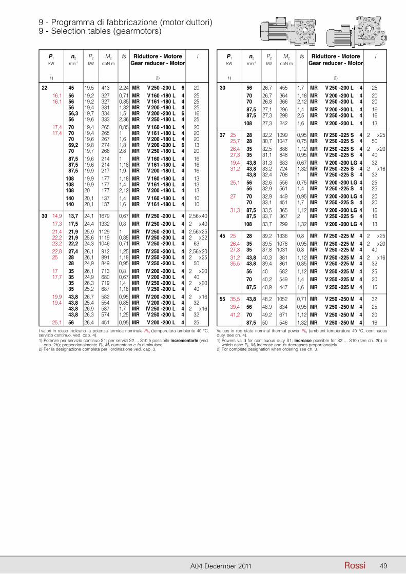
P1 n2 P2 M2 fs Riduttore - Motore i kW min-1 kW daN m Gear reducer - Motor
1) 2)
P1 n2 P2 M2 fs Riduttore - Motore i kW min-1 kW daN m Gear reducer - Motor
1) 2)
49A04 December 2011
9 - Programma di fabbricazione (motoriduttori)9 - Selection tables (gearmotors)
P1 n2 P2 M2 fs Riduttore - Motore i kW min-1 kW daN m Gear reducer - Motor
1) 2)
22 45 19,5 413 2,24 MR V 250 - 200 L 6 20 16,1 56 19,2 327 0,71 MR V 160 - 180 L 4 25 16,1 56 19,2 327 0,85 MR V 161 - 180 L 4 25 56 19,4 331 1,32 MR V 200 - 180 L 4 25 56,3 19,7 334 1,5 MR V 200 - 200 L 6 16 56 19,6 333 2,36 MR V 250 - 180 L 4 25 17,4 70 19,4 265 0,85 MR V 160 - 180 L 4 20 17,4 70 19,4 265 1 MR V 161 - 180 L 4 20 70 19,6 267 1,6 MR V 200 - 180 L 4 20 69,2 19,8 274 1,8 MR V 200 - 200 L 6 13 70 19,7 268 2,8 MR V 250 - 180 L 4 20 87,5 19,6 214 1 MR V 160 - 180 L 4 16 87,5 19,6 214 1,18 MR V 161 - 180 L 4 16 87,5 19,9 217 1,9 MR V 200 - 180 L 4 16 108 19,9 177 1,18 MR V 160 - 180 L 4 13 108 19,9 177 1,4 MR V 161 - 180 L 4 13 108 20 177 2,12 MR V 200 - 180 L 4 13 140 20,1 137 1,4 MR V 160 - 180 L 4 10 140 20,1 137 1,6 MR V 161 - 180 L 4 10
30 14,9 13,7 24,1 1679 0,67 MR IV 250 - 200 L 4 22,56 x 40 17,3 17,5 24,4 1332 0,8 MR IV 250 - 200 L 4 22 x 40 21,4 21,9 25,9 1129 1 MR IV 250 - 200 L 4 22,56 x 25 22,2 21,9 25,6 1119 0,85 MR IV 250 - 200 L 4 22 x 32 23,2 22,2 24,3 1046 0,71 MR V 250 - 200 L 4 63 22,8 27,4 26,1 912 1,25 MR IV 250 - 200 L 4 22,56 x 20 25 28 26,1 891 1,18 MR IV 250 - 200 L 4 22 x 25 28 24,9 849 0,95 MR V 250 - 200 L 4 50 17 35 26,1 713 0,8 MR IV 200 - 200 L 4 22 x 20 17,7 35 24,9 680 0,67 MR V 200 - 200 L 4 40 35 26,3 719 1,4 MR IV 250 - 200 L 4 22 x 20 35 25,2 687 1,18 MR V 250 - 200 L 4 40 19,9 43,8 26,7 582 0,95 MR IV 200 - 200 L 4 22 x 16 19,4 43,8 25,4 554 0,85 MR V 200 - 200 L 4 32 43,8 26,9 587 1,7 MR IV 250 - 200 L 4 22 x 16 43,8 26,3 574 1,25 MR V 250 - 200 L 4 32 25,1 56 26,4 451 0,95 MR V 200 - 200 L 4 25
P1 n2 P2 M2 fs Riduttore - Motore i kW min-1 kW daN m Gear reducer - Motor
1) 2)
30 56 26,7 455 1,7 MR V 250 - 200 L 4 25 70 26,7 364 1,18 MR V 200 - 200 L 4 20 70 26,8 366 2,12 MR V 250 - 200 L 4 20 87,5 27,1 296 1,4 MR V 200 - 200 L 4 16 87,5 27,3 298 2,5 MR V 250 - 200 L 4 16 108 27,3 242 1,6 MR V 200 - 200 L 4 13
37 25 28 32,2 1099 0,95 MR IV 250 - 225 S 4 22 x 25 25,7 28 30,7 1047 0,75 MR V 250 - 225 S 4 50 26,4 35 32,5 886 1,12 MR IV 250 - 225 S 4 22 x 20 27,3 35 31,1 848 0,95 MR V 250 - 225 S 4 40 19,4 43,8 31,3 683 0,67 MR V 200 - 200 LG 4 32 31,2 43,8 33,2 724 1,32 MR IV 250 - 225 S 4 22 x 16 43,8 32,4 708 1 MR V 250 - 225 S 4 32 25,1 56 32,6 556 0,75 MR V 200 - 200 LG 4 25 56 32,9 561 1,4 MR V 250 - 225 S 4 25 27 70 32,9 449 0,95 MR V 200 - 200 LG 4 20 70 33,1 451 1,7 MR V 250 - 225 S 4 20 31,3 87,5 33,5 365 1,12 MR V 200 - 200 LG 4 16 87,5 33,7 367 2 MR V 250 - 225 S 4 16 108 33,7 299 1,32 MR V 200 - 200 LG 4 13
45 25 28 39,2 1336 0,8 MR IV 250 - 225 M 4 22 x 25 26,4 35 39,5 1078 0,95 MR IV 250 - 225 M 4 22 x 20 27,3 35 37,8 1031 0,8 MR V 250 - 225 M 4 40 31,2 43,8 40,3 881 1,12 MR IV 250 - 225 M 4 22 x 16 35,5 43,8 39,4 861 0,85 MR V 250 - 225 M 4 32 56 40 682 1,12 MR V 250 - 225 M 4 25 70 40,2 549 1,4 MR V 250 - 225 M 4 20 87,5 40,9 447 1,6 MR V 250 - 225 M 4 16
55 35,5 43,8 48,2 1052 0,71 MR V 250 - 250 M 4 32 39,4 56 48,9 834 0,95 MR V 250 - 250 M 4 25 41,2 70 49,2 671 1,12 MR V 250 - 250 M 4 20 87,5 50 546 1,32 MR V 250 - 250 M 4 16
I valori in rosso indicano la potenza termica nominale PtN (temperatura ambiente 40 °C, servizio continuo, ved. cap. 4).1) Potenze per servizio continuo S1; per servizi S2 ... S10 è possibile incrementarle (ved.
cap. 2b); proporzionalmente P2, M2 aumentano e fs diminuisce.2) Per la designazione completa per l’ordinazione ved. cap. 3.
Values in red state nominal thermal power PtN (ambient temperature 40 °C, continuous duty, see ch. 4).1) Powers valid for continuous duty S1; increase possible for S2 ... S10 (see ch. 2b) in
which case P2, M2 increase and fs decreases proportionately.2) For complete designation when ordering see ch. 3.
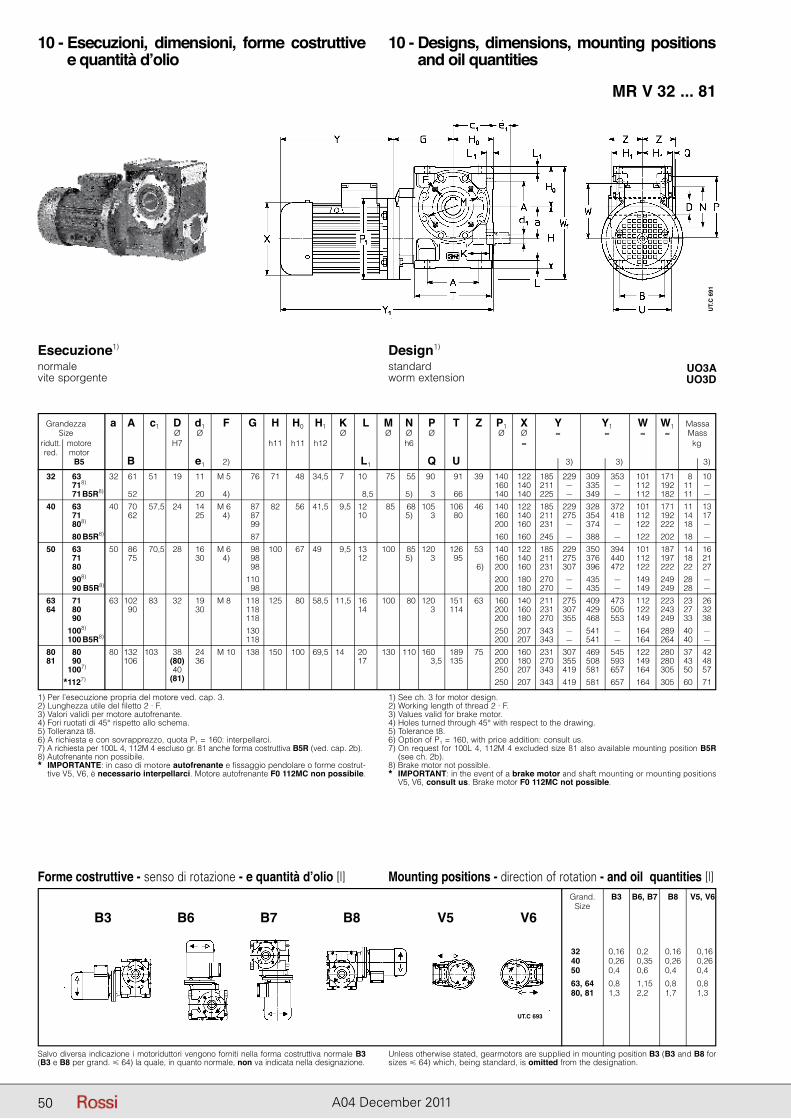
50 A04 December 2011
10 - Esecuzioni, dimensioni, forme costruttive e quantità d’olio
10 - Designs, dimensions, mounting positions and oil quantities
MR V 32 ... 81
UO3AUO3D
1) Per l’esecuzione propria del motore ved. cap. 3.2) Lunghezza utile del filetto 2 · F.3) Valori validi per motore autofrenante.4) Fori ruotati di 45° rispetto allo schema.5) Tolleranza t8.6) A richiesta e con sovrapprezzo, quota P1 = 160: interpellarci.7) A richiesta per 100L 4, 112M 4 escluso gr. 81 anche forma costruttiva B5R (ved. cap. 2b).8) Autofrenante non possibile.* IMPORTANTE: in caso di motore autofrenante e fissaggio pendolare o forme costrut-
tive V5, V6, è necessario interpellarci. Motore autofrenante F0 112MC non possibile.
1) See ch. 3 for motor design.2) Working length of thread 2 · F.3) Values valid for brake motor.4) Holes turned through 45° with respect to the drawing.5) Tolerance t8.6) Option of P1 = 160, with price addition: consult us.7) On request for 100L 4, 112M 4 excluded size 81 also available mounting position B5R
(see ch. 2b).8) Brake motor not possible.* IMPORTANT: in the event of a brake motor and shaft mounting or mounting positions
V5, V6, consult us. Brake motor F0 112MC not possible.
Grandezza a A c1 D d1 F G H H0 H1 K L M N P T Z P1 X Y Y1 W W1 Massa Size Ø Ø Ø Ø Ø Ø Ø Ø ≈ ≈ ≈ ≈ Mass ridutt. motore H7 h11 h11 h12 h6 ≈ kg red. motor B5 B e1 2) L1 Q U 3) 3) 3)
Esecuzione1) normalevite sporgente
Design1) standardworm extension
185 229 309 353 101 171 8 10 211 – 335 – 112 192 11 – 225 – 349 – 112 182 11 – 185 229 328 372 101 171 11 13 211 275 354 418 112 192 14 17 231 – 374 – 122 222 18 – 245 – 388 – 122 202 18 – 185 229 350 394 101 187 14 16 211 275 376 440 112 197 18 21 231 307 396 472 122 222 22 27 270 – 435 – 149 249 28 – 270 – 435 – 149 249 28 – 211 275 409 473 112 223 23 26 231 307 429 505 122 243 27 32 270 355 468 553 149 249 33 38 343 – 541 – 164 289 40 – 343 – 541 – 164 264 40 – 231 307 469 545 122 280 37 42 270 355 508 593 149 280 43 48 343 419 581 657 164 305 50 57 343 419 581 657 164 305 60 71
32 *163 32 61 51,5 19 11 M 50 76 71 48 34,5 7,5 10,5 75 55 190,5 91 39 140 122 *1718)B5 19,5 160 140 *171 B5R8) 52 20 4) 8,5 5) 193,5 66 140 140 40 *163 40 70 57,5 24 14 M 60 87 82 56 41,5 9,5 12,5 85 68 105,5 106 46 140 122 *1717 62 25 4) 87 10,5 5) 193,5 80 160 140 *1808) 99 ,5 200 160 *180 B5R8) 87 ,5 160 160 50 *1634) 50 86 70,5 28 16 M 60 98 100 67 49,5 9,5 13,5 100 85 120,5 126 53 140 122 *1717) 75 30 4) 98 12,5 5) 193,5 95 160 140 *1807) 98 1,5 6) 200 160 *1908) 110 195 200 180 *190 B5R8) 98 195 200 180 63 *1714) 63 102 83,5 32 19 M 80 118 125 80 58,5 11,5 16,5 100 80 120,5 151 63 160 140 64 *1807) 90 30 118 14,5 193,5 114 200 160 *1907) 118 19,5 200 180 *1008) 130 250 207 *100 B5R8) 118 19,5 200 207 80 *1804) 80 132 103,5 38 24 M 10 138 150 100 69,5 14,5 20,5 130 110 160,5 189 75 200 160 81 *1907) 106 (80) 36 17,5 193,5 135 200 180 *1007) 40 195 250 207 *1127) (81) 19 250 207
UT.
C 6
91
Forme costruttive - senso di rotazione - e quantità d’olio [l]
Salvo diversa indicazione i motoriduttori vengono forniti nella forma costruttiva normale B3 (B3 e B8 per grand. � 64) la quale, in quanto normale, non va indicata nella designazione.
Unless otherwise stated, gearmotors are supplied in mounting position B3 (B3 and B8 for sizes � 64) which, being standard, is omitted from the designation.
Mounting positions - direction of rotation - and oil quantities [l] Grand. B3 B6, B7 B8 V5, V6 Size
32, 81 0,16 0,22 0,16 0,16 40, 81 0,26 0,35 0,26 0,26 50, 81 0,46 0,62 0,42 0,42
63, 64 0,86 1,15 0,82 0,82 80, 81 1,36 2,22 1,72 1,32
B3 B6 B7 B8 V5 V6
UT.C 693
50
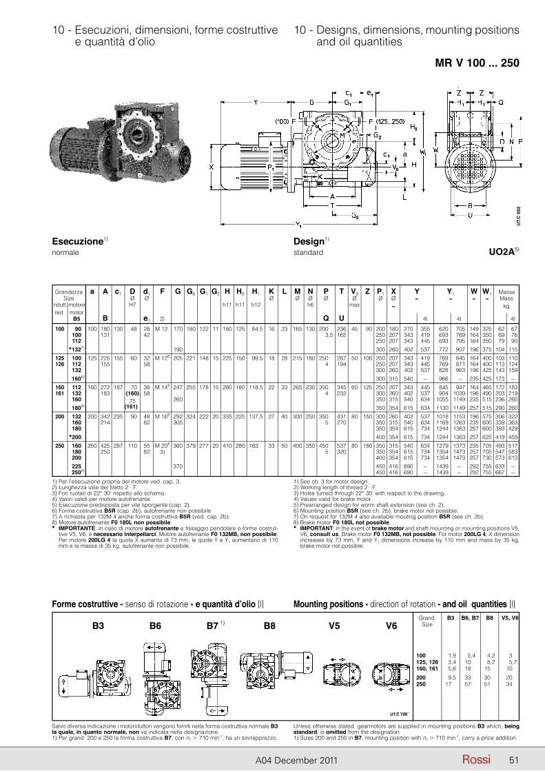
51A04 December 2011
10 - Esecuzioni, dimensioni, forme costruttive e quantità d’olio
10 - Designs, dimensions, mounting positions and oil quantities
MR V 100 ... 250
UO2A5)
Forme costruttive - senso di rotazione - e quantità d’olio [l]
Salvo diversa indicazione i motoriduttori vengono forniti nella forma costruttiva normale B3 la quale, in quanto normale, non va indicata nella designazione.1) Per grand. 200 e 250 la forma costruttiva B7, con n1 � 710 min-1, ha un sovrapprezzo.
Unless otherwise stated, gearmotors are supplied in mounting positions B3 which, being standard, is omitted from the designation.1) Sizes 200 and 250 in B7, mounting position with n1 � 710 min-1, carry a price addition.
Mounting positions - direction of rotation - and oil quantities [l] Grand. B3 B6, B7 B8 V5, V6 Size
100, 081 1,9 5,4 4,2 3,5 125, 126 3,4 10,5 8,2 5,7 160, 161 5,6 18,5 15,5 10,5
200, 081 9,5 33,5 30,5 20,5 250, 081 17,3 57,5 51,5 34,5
B3 B6 B7 B8 V5 V61)
Esecuzione1) normale
Design1) standard
Grandezza a A c1 D d1 F G G0 G1 G2 H H0 H1 K L M N P T V0 Z Size Ø Ø Ø Ø Ø Ø Ø ridutt. motore H7 h11 h11 h12 h6 max red. motor B5 B e1 2) Q U 100 *1907) 100 180 130 48 28 M 124 170 180 122 11 180 125 84,5 16 23 165 130 200,5 236 45 90 *1007) 131 42 203,5 165 *1127) *1327) 190 125 *1007) 125 225 155 60 32 M 128 205 221 148 15 225 150 99,5 18 28 215 180 250,5 287 50 106 126 *1127) 155 58 204,5 194 *1327) *1606) 160 *1127) 160 272 187 70 38 M 148 247 255 178 15 280 180 118,5 22 33 265 230 300,5 345 60 125 161 *1327) 183 (160) 58 204,5 232 *1607) 75 260 *1808) (161) 200 *1327) 200 342 235 90 48 M 168 292 324 222 20 335 225 137,5 27 40 300 250 350,5 431 80 150 *1607) 214 82 305 205,5 270 *1807) *2007) 250 *1607) 250 425 287 110 55 M 208 360 379 277 20 410 280 163,5 33 50 400 350 450,5 537 80 180 *1807) 250 82 3) 205,5 320 *2007) *2257) 370 *2506)
P1 X Y Y1 W W1 Massa Ø Ø ≈ ≈ ≈ ≈ Mass ≈ kg 4) 4) 4) 200 180 270 355 620 705 149 325 62 67 250 207 343 419 693 769 164 350 69 76 250 207 343 445 693 795 164 350 79 90 300 260 402 537 772 907 196 375 104 115 250 207 343 419 769 845 164 400 103 110 250 207 343 445 769 871 164 400 113 124 300 260 402 537 828 963 196 425 143 159 300 315 540 – 966 – 235 425 173 – 250 207 343 445 845 947 164 465 172 183 300 260 402 537 904 1039 196 490 203 219 350 315 540 634 1055 1149 235 515 236 260 350 354 615 634 1130 1149 257 515 290 260 300 260 402 537 1018 1153 196 575 306 322 350 315 540 634 1169 1263 235 600 339 363 350 354 615 734 1244 1363 257 600 393 429 400 354 615 734 1244 1363 257 625 419 459 350 315 540 634 1279 1373 235 705 493 517 350 354 615 734 1354 1473 257 705 547 583 400 354 615 734 1354 1473 257 730 573 613 450 416 690 – 1439 – 292 755 633 – 450 416 690 – 1439 – 292 755 667 –
1) Per l’esecuzione propria del motore ved. cap. 3.2) Lunghezza utile del filetto 2 · F.3) Fori ruotati di 22° 30’ rispetto allo schema.4) Valori validi per motore autofrenante.5) Esecuzione predisposta per vite sporgente (cap. 2).6) Forma costruttiva B5R (cap. 2b), autofrenante non possibile.7) A richiesta per 132M 4 anche forma costruttiva B5R (ved. cap. 2b).8) Motore autofrenante F0 180L non possibile.* IMPORTANTE: in caso di motore autofrenante e fissaggio pendolare o forme costrut-
tive V5, V6, è necessario interpellarci. Motore autofrenante F0 132MB, non possibile. Per motore 200LG 4 la quota X aumenta di 73 mm, le quote Y e Y1 aumentano di 110 mm e la massa di 35 kg, autofrenante non possibile.
1) See ch. 3 for motor design.2) Working length of thread 2 · F.3) Holes turned through 22° 30’ with respect to the drawing.4) Values valid for brake motor.5) Prearranged design for worm shaft extension (see ch. 2).6) Mounting position B5R (see ch. 2b), brake motor not possible.7) On request for 132M 4 also available mouting position B5R (see ch. 2b).8) Brake motor F0 180L not possible.* IMPORTANT: in the event of brake motor and shaft mounting or mounting positions V5,
V6, consult us. Brake motor F0 132MB, not possible. For motor 200LG 4, X dimension increases by 73 mm, Y and Y1 dimensions increase by 110 mm and mass by 35 kg, brake motor not possible.
UT.
C 6
92
UT.C 700
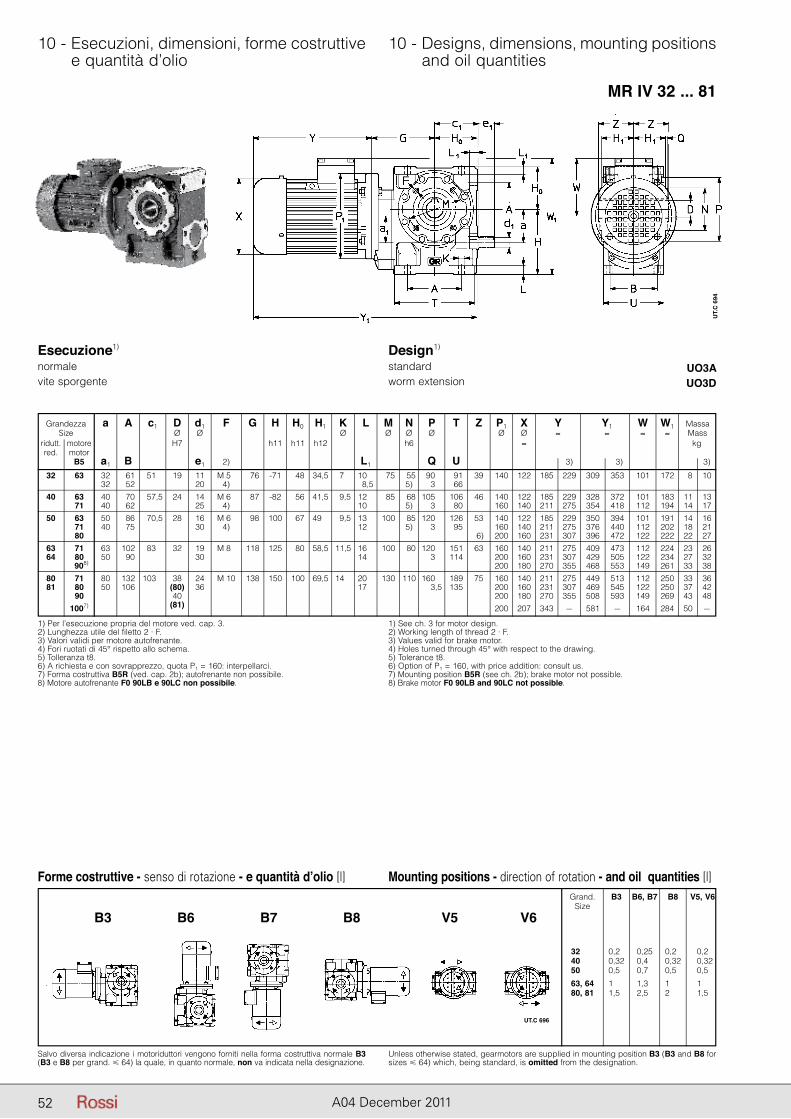
52 A04 December 2011
10 - Esecuzioni, dimensioni, forme costruttive e quantità d’olio
10 - Designs, dimensions, mounting positions and oil quantities
MR IV 32 ... 81
UO3AUO3D
1) Per l’esecuzione propria del motore ved. cap. 3.2) Lunghezza utile del filetto 2 · F.3) Valori validi per motore autofrenante.4) Fori ruotati di 45° rispetto allo schema.5) Tolleranza t8.6) A richiesta e con sovrapprezzo, quota P1 = 160: interpellarci.7) Forma costruttiva B5R (ved. cap. 2b); autofrenante non possibile.8) Motore autofrenante F0 90LB e 90LC non possibile.
1) See ch. 3 for motor design.2) Working length of thread 2 · F.3) Values valid for brake motor.4) Holes turned through 45° with respect to the drawing.5) Tolerance t8.6) Option of P1 = 160, with price addition: consult us.7) Mounting position B5R (see ch. 2b); brake motor not possible.8) Brake motor F0 90LB and 90LC not possible.
Grandezza a A c1 D d1 F G H H0 H1 K L M N P T Z P1 X Y Y1 W W1 Massa Size Ø Ø Ø Ø Ø Ø Ø Ø ≈ ≈ ≈ ≈ Mass ridutt. motore H7 h11 h11 h12 h6 ≈ kg red. motor B5 a1 B e1 2) L1 Q U 3) 3) 3)
Esecuzione1) normalevite sporgente
Design1) standardworm extension
185 229 309 353 101 172 8 10 185 229 328 372 101 183 11 13 211 275 354 418 112 194 14 17 185 229 350 394 101 191 14 16 211 275 376 440 112 202 18 21 231 307 396 472 122 222 22 27 211 275 409 473 112 224 23 26 231 307 429 505 122 234 27 32 270 355 468 553 149 261 33 38 211 275 449 513 112 250 33 36 231 307 469 545 122 250 37 42 270 355 508 593 149 269 43 48 343 – 581 – 164 284 50 –
32 1634) 32 61 51,5 19 11 M 50 76 -71 48 34,5 7,5 10,5 75 55 190,5 91 39 140 122 *1 32 52 20 4) 8,5 5) 193,5 66 40 1634) 40 70 57,5 24 14 M 60 87 -82 56 41,5 9,5 12,5 85 68 105,5 106 46 140 122 1717) 40 62 25 4) 10,5 5) ,3 80 160 140 50 1634) 50 86 70,5 28 16 M 60 98 100 67 49,5 9,5 13,5 100 85 120,5 126 53 140 122 1717) 40 75 30 4) 12,5 5) 193,5 95 160 140 1807) 1,5 6) 200 160 63 1714) 63 102 83,5 32 19 M 80 118 125 80 58,5 11,5 16,5 100 80 120,5 151 63 160 140 64 1807) 50 90 30 14,5 193,5 114 200 160 1908) 19,5 200 180 80 1714) 80 132 103,5 38 24 M 10 138 150 100 69,5 14,5 20,5 130 110 160,5 189 75 160 140 81 1807) 50 106 (80) 36 17,5 193,5 135 200 160 1907) 40 195 200 180 1007) (81) 19 200 207
Forme costruttive - senso di rotazione - e quantità d’olio [l]
Salvo diversa indicazione i motoriduttori vengono forniti nella forma costruttiva normale B3 (B3 e B8 per grand. � 64) la quale, in quanto normale, non va indicata nella designazione.
Unless otherwise stated, gearmotors are supplied in mounting position B3 (B3 and B8 for sizes � 64) which, being standard, is omitted from the designation.
Mounting positions - direction of rotation - and oil quantities [l] Grand. B3 B6, B7 B8 V5, V6 Size
32, 81 0,26 0,25 0,26 0,26 40, 81 0,32 0,45 0,32 0,32 50, 81 0,56 0,72 0,52 0,52
63, 64 1,86 1,30 1,82 1,82 80, 81 1,56 2,52 2,82 1,52
UT.C 696
B3 B6 B7 B8 V5 V6
UT.
C 6
94
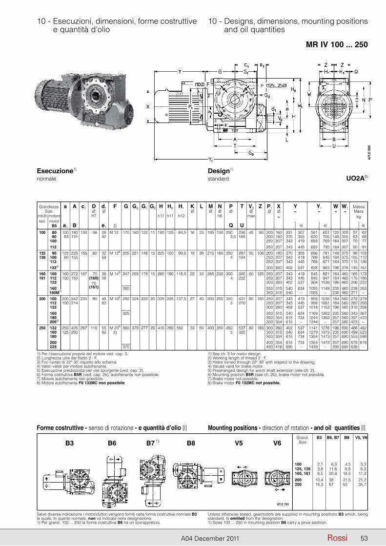
53A04 December 2011
10 - Esecuzioni, dimensioni, forme costruttive e quantità d’olio
10 - Designs, dimensions, mounting positions and oil quantities
MR IV 100 ... 250
UO2A5)
Forme costruttive - senso di rotazione - e quantità d’olio [l]
Salvo diversa indicazione i motoriduttori vengono forniti nella forma costruttiva normale B3 la quale, in quanto normale, non va indicata nella designazione.1) Per grand. 100 ... 250 la forma costruttiva B6 ha un sovrapprezzo.
Unless otherwise stated, gearmotors are supplied in mounting positions B3 which, being standard, is omitted from the designation.1) Sizes 100 ... 250 in mounting position B6 carry a price addition.
Mounting positions - direction of rotation - and oil quantities [l] Grand. B3 B6, B7 B8 V5, V6 Size
100, 081 2,1 6,3 4,5 3,3 125, 126 3,8 11,6 8,8 6,3 160, 161 6,5 20,8 16,5 11,2
200, 081 10,4 38,5 31,5 21,2 250, 081 18,3 67,5 53,5 35,7
B3 B6 B7 B8 V5 V61)
Esecuzione1) normale
Design1) standard
Grandezza a A c1 D d1 F G G0 G1 G2 H H0 H1 K L M N P T V0 Z Size Ø Ø Ø Ø Ø Ø Ø ridutt. motore H7 h11 h11 h12 h6 max red. motor B5 a1 B e1 2) Q U
P1 X Y Y1 W W1 Massa Ø Ø ≈ ≈ ≈ ≈ Mass ≈ kg 4) 4) 4) 200 160 231 307 581 657 122 305 57 62 200 180 270 355 620 705 149 305 63 68 250 207 343 419 693 769 164 307 70 77 250 207 343 445 693 795 164 307 80 91 200 180 270 355 696 781 149 375 98 103 250 207 343 419 769 845 164 375 105 112 250 207 343 445 769 871 164 375 115 126 300 260 402 537 828 963 196 376 145 161 250 207 343 419 845 921 164 460 165 172 250 207 343 445 845 947 164 460 175 186 300 260 402 537 904 1039 196 460 206 222 350 315 540 634 1055 1149 235 460 239 263 350 315 540 – 1055 – 235 460 271 – 250 207 343 419 959 1035 164 560 272 279 250 207 343 445 959 1061 164 560 282 293 300 260 402 537 1018 1153 196 560 310 326 350 315 540 634 1169 1263 235 560 343 367 350 354 615 734 1244 1363 257 560 397 433 350 354 615 – 1244 – 257 560 423 – 300 260 402 537 1141 1276 196 690 466 482 350 315 540 634 1279 1373 235 690 499 523 350 354 615 734 1354 1473 257 690 553 589 400 354 615 734 1354 1473 257 690 579 619 450 416 690 – 1439 – 292 690 639 –
1) Per l’esecuzione propria del motore ved. cap. 3.2) Lunghezza utile del filetto 2 · F.3) Fori ruotati di 22° 30’ rispetto allo schema.4) Valori validi per motore autofrenante.5) Esecuzione predisposta per vite sporgente (ved. cap. 2).6) Forma costruttiva B5R (ved. cap. 2b), autofrenante non possibile.7) Motore autofrenante non possibile.8) Motore autofrenante F0 132MC non possibile.
1) See ch. 3 for motor design.2) Working length of thread 2 · F.3) Holes turned through 22° 30’ with respect to the drawing.4) Values valid for brake motor.5) Prearranged design for worm shaft extension (see ch. 2).6) Mounting position B5R (see ch. 2b), brake motor not possible.7) Brake motor not possible.8) Brake motor F0 132MC not possible.
100 1807) 100 180 130 48 28 M 124) 170 180 122 11 180 125 84,5 16 23 165 130 200,5 236 45 90 907) 63 131 42 203,5 165 1007) 1127) 125 907) 125 225 155 60 32 M 128 205 221 148 15 225 150 99,5 18 28 215 180 250,5 287 50 106 126 1007) 80 155 58 204,5 194 1127) 1328) 160 1007) 160 272 187 70 38 M 148 247 255 178 15 280 180 118,5 22 33 265 230 300,5 345 60 125 161 1127) 100 183 (160) 58 204,5 232 1327) 75 1607) (161) 260 20,5 180M7) 200 1007) 200 342 235 90 48 M 168 292 324 222 20 335 225 137,5 27 40 300 250 350,5 431 80 150 1127) 100 214 82 205,5 270 1327) 1607) 305 20,5 1807) 20,5 2006) 250 1327) 250 425 287 110 55 M 208 360 379 277 20 410 280 163,5 33 50 400 350 450,5 537 80 180 1607) 125 250 82 3) 205,5 320 1807) 2007) 2256) 370
UT.
C 6
95
UT.C 701
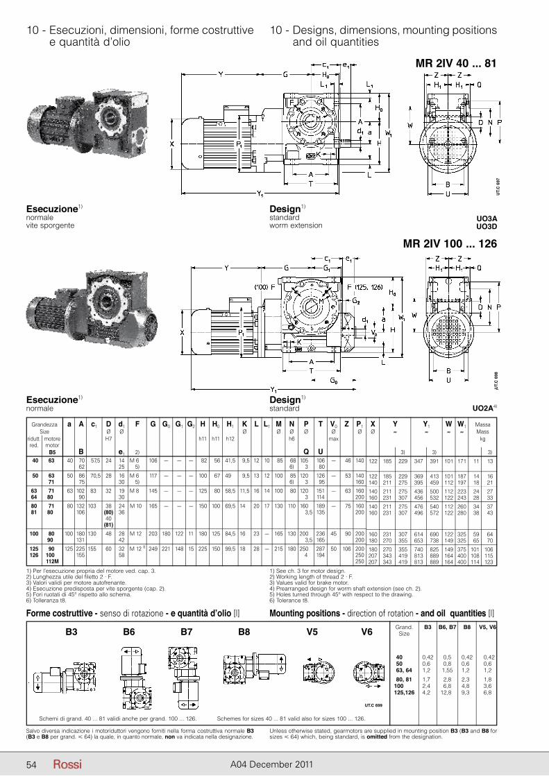
54 A04 December 2011
10 - Esecuzioni, dimensioni, forme costruttive e quantità d’olio
10 - Designs, dimensions, mounting positions and oil quantities
MR 2IV 40 ... 81
MR 2IV 100 ... 126
UO3AUO3D
UO2A4)
Esecuzione1) normalevite sporgente
Esecuzione1) normale
Design1) standardworm extension
Design1) standard
1) Per l’esecuzione propria del motore ved. cap. 3.2) Lunghezza utile del filetto 2 · F.3) Valori validi per motore autofrenante.4) Esecuzione predisposta per vite sporgente (cap. 2).5) Fori ruotati di 45° rispetto allo schema.6) Tolleranza t8.
1) See ch. 3 for motor design.2) Working length of thread 2 · F.3) Values valid for brake motor.4) Prearranged design for worm shaft extension (see ch. 2).5) Holes turned through 45° with respect to the drawing.6) Tolerance t8.
Grandezza a A c1 D d1 F G G0 G1 G2 H H0 H1 K L L1 M N P T V0 Z P1 X Y Y1 W W1 Massa Size Ø Ø Ø Ø Ø Ø Ø Ø Ø ≈ ≈ ≈ ≈ Mass ridutt. motore H7 h11 h11 h12 h6 max kg red. motor B5 B e1 2) Q U 3) 3) 3)
122 185 229 347 391 101 171 11 13
122 185 229 369 413 101 187 14 16 140 211 275 395 459 112 197 18 21
140 211 275 436 500 112 223 24 27 160 231 307 456 532 122 243 28 33
140 211 275 476 540 112 260 34 37 160 231 307 496 572 122 280 38 43
160 231 307 614 690 122 325 59 64 180 270 355 653 738 149 325 65 70
180 270 355 740 825 149 375 101 106 207 343 419 813 889 164 400 108 115 207 343 419 813 889 164 400 114 123
40 63M 40 70 57,5 24 14 M 62 8 106 – – – 82 56 41,5 9,5 12 10 85 68 105,5 106 – 46 140 62 25 5) 6) 3,5 80
50 63M 50 86 70,5 28 16 M 62 8 117 – – – 100 67 49,5 9,5 13 12 100 85 120,5 126 – 53 140 71M 75 30 5) 6) 3,5 95 160
63 71M 63 102 83,5 32 19 M 82 8 145 – – – 125 80 58,5 11,5 16 14 100 80 120,5 151 – 63 160 64 80M 90 30 3,5 114 200
80 71M 80 132 103,5 38 24 M 10 8 165 – – – 150 100 69,5 14,5 20 17 130 110 160,5 189 – 75 160 81 80M 106 (80) 36 3,5 135 200 40 (81)
100 80M 100 180 130,5 48 28 M 12 8 203 180 122 11 180 125 84,5 16,5 23 – 165 130 200,5 236 45 90 200 90M 131 42 3,5 165 200
125 90M 125 225 155,5 60 32 M 12 8 249 221 148 15 225 150 99,5 18,5 28 – 215 180 250,5 287 50 106 200 126 100M 155 58 4 194 250 112M 250
UT.
C 6
97U
T.C
698
Forme costruttive - senso di rotazione - e quantità d’olio [l]
Salvo diversa indicazione i motoriduttori vengono forniti nella forma costruttiva normale B3(B3 e B8 per grand. � 64) la quale, in quanto normale, non va indicata nella designazione.
Unless otherwise stated, gearmotors are supplied in mounting position B3 (B3 and B8 for sizes � 64) which, being standard, is omitted from the designation.
Mounting positions - direction of rotation - and oil quantities [l] Grand. B3 B6, B7 B8 V5, V6 Size
40, 081 0,42 0,52 0,42 0,42 50, 801 0,66 0,85 0,60 0,60 63, 640 1,26 1,552 1,22 1,22
80, 810 1,76 2,85 2,32 1,82 100,126 2,46 6,82 4,82 3,62 125,126 4,26 12,82 9,32 6,82
B3 B6 B7 B8 V5 V6
Schemi di grand. 40 ... 81 validi anche per grand. 100 ... 126. Schemes for sizes 40 ... 81 valid also for sizes 100 ... 126.
UT.C 699
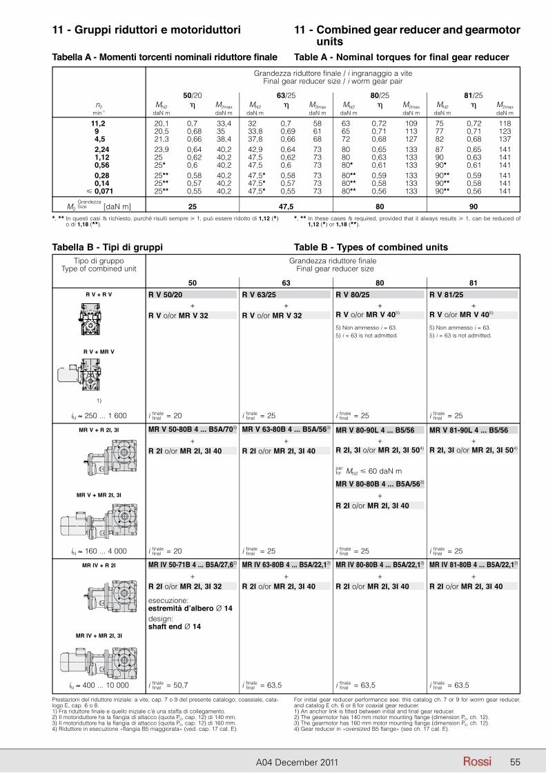
55A04 December 2011
11 - Gruppi riduttori e motoriduttori 11 - Combined gear reducer and gearmotor units
Tabella A - Momenti torcenti nominali riduttore finale Table A - Nominal torques for final gear reducerGrandezza riduttore finale / i ingranaggio a vite
Final gear reducer size / i worm gear pair
50/20 63/25 80/25 81/25 n2 MN2 � M2max MN2 � M2max MN2 � M2max MN2 � M2max min-1 daN m daN m daN m daN m daN m daN m daN m daN m
11,2 20,1 0,7 33,4 32 0,7 58 63 0,72 109 75 0,72 118 9 20,5 0,68 35 33,8 0,69 61 65 0,71 113 77 0,71 123 4,5 21,3 0,66 38,4 37,8 0,66 68 72 0,68 127 82 0,68 137 2,24 23,9 0,64 40,2 42,9 0,64 73 80 0,65 133 87 0,65 141 1,12 25 0,62 40,2 47,5 0,62 73 80 0,63 133 90 0,63 141 0,56 25* 0,6 40,2 47,5 0,6 73 80* 0,61 133 90* 0,61 141 0,28 25** 0,58 40,2 47,5* 0,58 73 80** 0,59 133 90** 0,59 141 0,14 25** 0,57 40,2 47,5* 0,57 73 80** 0,58 133 90** 0,58 141 � 0,071 25** 0,55 40,2 47,5* 0,55 73 80** 0,56 133 90** 0,56 141
M2 GrandezzaSize [daN m] 25 47,5 80 90
*, ** In questi casi fs richiesto, purché risulti sempre � 1, può essere ridotto di 1,12 (*) o di 1,18 (**).
*, ** In these cases fs required, provided that it always results � 1, can be reduced of 1,12 (*) or 1,18 (**).
Prestazioni del riduttore iniziale: a vite, cap. 7 o 9 del presente catalogo; coassiale, cata-logo E, cap. 6 o 8.1) Fra riduttore finale e quello iniziale c’è una staffa di collegamento.2) Il motoriduttore ha la flangia di attacco (quota P0, cap. 12) di 140 mm.3) Il motoriduttore ha la flangia di attacco (quota P0, cap. 12) di 160 mm.4) Riduttore in esecuzione «flangia B5 maggiorata» (ved. cap. 17 cat. E).
For initial gear reducer performance see: this catalog ch. 7 or 9 for worm gear reducer, and catalog E ch. 6 or 8 for coaxial gear reducer.1) An anchor link is fitted between initial and final gear reducer.2) The gearmotor has 140 mm motor mounting flange (dimension P0, ch. 12).3) The gearmotor has 160 mm motor mounting flange (dimension P0, ch. 12).4) Gear reducer in «oversized B5 flange» (see ch. 17 cat. E).
Tabella B - Tipi di gruppi Table B - Types of combined units Tipo di gruppo Grandezza riduttore finale Type of combined unit Final gear reducer size
50 63 80 81 R V + R V R V 50/20 R V 63/25 R V 80/25 R V 81/25 + + + + R V o/or MR V 32 R V o/or MR V 32 R V o/or MR V 405)
R V o/or MR V 405)
5) Non ammesso i = 63. 5) Non ammesso i = 63. 5) i = 63 is not admitted. 5) i = 63 is not admitted.
R V + MR V
1)
iN ≈ 250 ... 1 600 i finalefinal = 20 i finale
final = 25 i finalefinal = 25 i finale
final = 25
MR V + R 2I, 3I MR V 50-80B 4 ... B5A/703) MR V 63-80B 4 ... B5A/563) MR V 80-90L 4 ... B5/56 MR V 81-90L 4 ... B5/56
+ + + + R 2I o/or MR 2I, 3I 40 R 2I o/or MR 2I, 3I 40 R 2I, 3I o/or MR 2I, 3I 504)
R 2I, 3I o/or MR 2I, 3I 504)
perfor MN2 � 60 daN m
MR V 80-80B 4 ... B5A/563)
MR V + MR 2I, 3I + R 2I o/or MR 2I, 3I 40
iN ≈ 160 ... 4 000 i finalefinal = 20 i finale
final = 25 i finalefinal = 25 i finale
final = 25
MR IV + R 2I MR IV 50-71B 4 ... B5A/27,62) MR IV 63-80B 4 ... B5A/22,13) MR IV 80-80B 4 ... B5A/22,13)
MR IV 81-80B 4 ... B5A/22,13)
+ + + + R 2I o/or MR 2I, 3I 32 R 2I o/or MR 2I, 3I 40 R 2I o/or MR 2I, 3I 40 R 2I o/or MR 2I, 3I 40
esecuzione: estremità d’albero Ø 14 design: shaft end Ø 14 MR IV + MR 2I, 3I
iN ≈ 400 ... 10 000 i finalefinal = 50,7 i finale
final = 63,5 i finalefinal = 63,5 i finale
final = 63,5
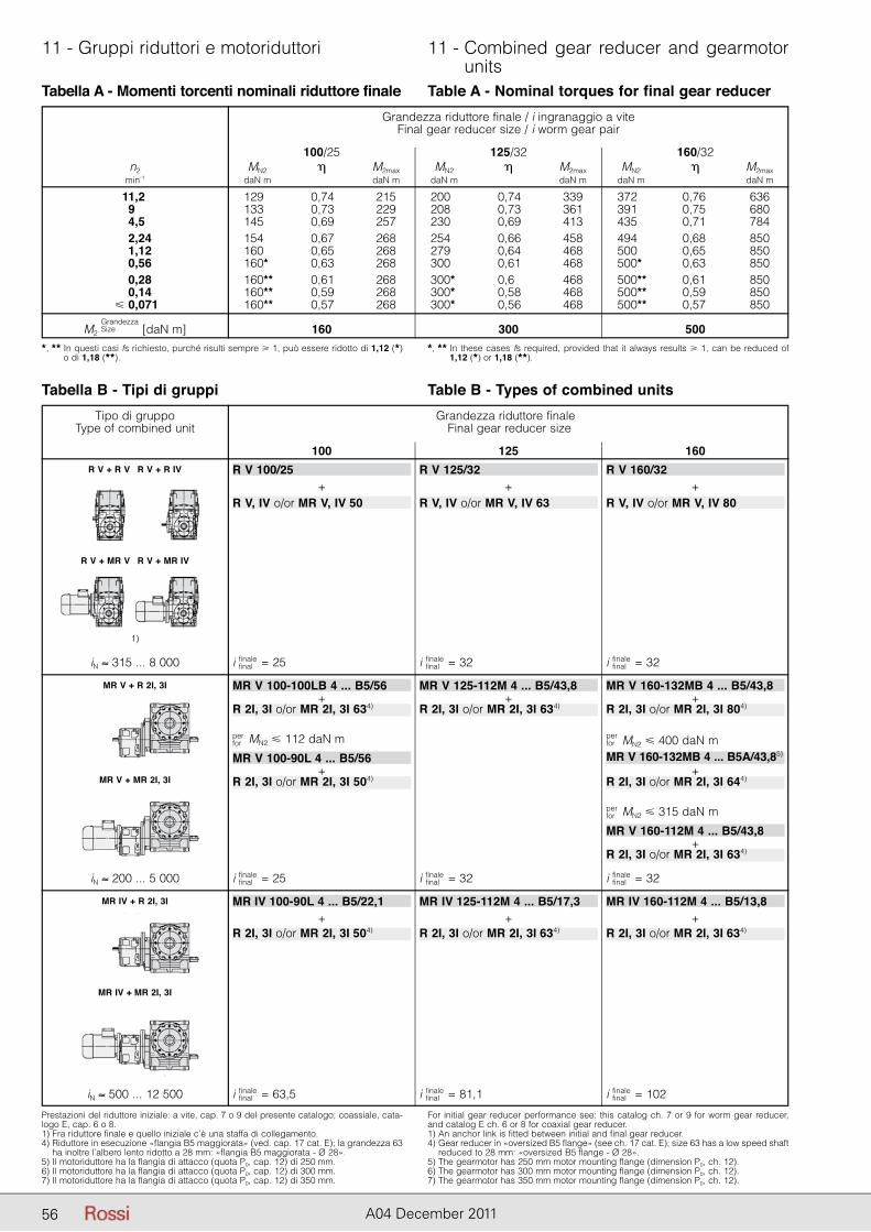
56 A04 December 2011
11 - Gruppi riduttori e motoriduttori 11 - Combined gear reducer and gearmotor units
Tabella A - Momenti torcenti nominali riduttore finale Table A - Nominal torques for final gear reducer
Tabella B - Tipi di gruppi Table B - Types of combined units
Grandezza riduttore finale / i ingranaggio a viteFinal gear reducer size / i worm gear pair
100/25 125/32 160/32 n2 MN2 � M2max MN2 � M2max MN2 � M2max min-1 daN m daN m daN m daN m daN m daN m
11,2 129 0,74 215 200 0,74 339 372 0,76 636 9 133 0,73 229 208 0,73 361 391 0,75 680 4,5 145 0,69 257 230 0,69 413 435 0,71 784 2,24 154 0,67 268 254 0,66 458 494 0,68 850 1,12 160 0,65 268 279 0,64 468 500 0,65 850 0,56 160* 0,63 268 300 0,61 468 500* 0,63 850 0,28 160** 0,61 268 300* 0,6 468 500** 0,61 850 0,14 160** 0,59 268 300* 0,58 468 500** 0,59 850 � 0,071 160** 0,57 268 300* 0,56 468 500** 0,57 850
M2 GrandezzaSize [daN m] 160 300 500
*, ** In questi casi fs richiesto, purché risulti sempre � 1, può essere ridotto di 1,12 (*) o di 1,18 (**).
*, ** In these cases fs required, provided that it always results � 1, can be reduced of 1,12 (*) or 1,18 (**).
Tipo di gruppo Grandezza riduttore finale Type of combined unit Final gear reducer size
100 125 160
Prestazioni del riduttore iniziale: a vite, cap. 7 o 9 del presente catalogo; coassiale, cata-logo E, cap. 6 o 8.1) Fra riduttore finale e quello iniziale c’è una staffa di collegamento.4) Riduttore in esecuzione «flangia B5 maggiorata» (ved. cap. 17 cat. E); la grandezza 63
ha inoltre l’albero lento ridotto a 28 mm: «flangia B5 maggiorata - Ø 28».5) Il motoriduttore ha la flangia di attacco (quota P0, cap. 12) di 250 mm.6) Il motoriduttore ha la flangia di attacco (quota P0, cap. 12) di 300 mm.7) Il motoriduttore ha la flangia di attacco (quota P0, cap. 12) di 350 mm.
For initial gear reducer performance see: this catalog ch. 7 or 9 for worm gear reducer, and catalog E ch. 6 or 8 for coaxial gear reducer.1) An anchor link is fitted between initial and final gear reducer.4) Gear reducer in «oversized B5 flange» (see ch. 17 cat. E); size 63 has a low speed shaft
reduced to 28 mm: «oversized B5 flange - Ø 28».5) The gearmotor has 250 mm motor mounting flange (dimension P0, ch. 12).6) The gearmotor has 300 mm motor mounting flange (dimension P0, ch. 12).7) The gearmotor has 350 mm motor mounting flange (dimension P0, ch. 12).
R V + R V R V + R IV R V 100/25 R V 125/32 R V 160/32 + + + R V, IV o/or MR V, IV 50 R V, IV o/or MR V, IV 63 R V, IV o/or MR V, IV 80
R V + MR V R V + MR IV
1)
iN ≈ 315 ... 8 000 i finalefinal = 25 i finale
final = 32 i finalefinal = 32
MR V + R 2I, 3I MR V 100-100LB 4 ... B5/56 MR V 125-112M 4 ... B5/43,8 MR V 160-132MB 4 ... B5/43,8 + + + R 2I, 3I o/or MR 2I, 3I 634)
R 2I, 3I o/or MR 2I, 3I 634) R 2I, 3I o/or MR 2I, 3I 804)
perfor MN2 � 112 daN m
perfor MN2 � 400 daN m
MR V 100-90L 4 ... B5/56 MR V 160-132MB 4 ... B5A/43,85)
+ + MR V + MR 2I, 3I R 2I, 3I o/or MR 2I, 3I 504)
R 2I, 3I o/or MR 2I, 3I 644)
perfor MN2 � 315 daN m
MR V 160-112M 4 ... B5/43,8 + R 2I, 3I o/or MR 2I, 3I 634)
iN ≈ 200 ... 5 000 i finalefinal = 25 i finale
final = 32 i finalefinal = 32
MR IV + R 2I, 3I MR IV 100-90L 4 ... B5/22,1 MR IV 125-112M 4 ... B5/17,3 MR IV 160-112M 4 ... B5/13,8 + + + R 2I, 3I o/or MR 2I, 3I 504)
R 2I, 3I o/or MR 2I, 3I 634) R 2I, 3I o/or MR 2I, 3I 634)
MR IV + MR 2I, 3I
iN ≈ 500 ... 12 500 i finalefinal = 63,5 i finale
final = 81,1 i finalefinal = 102
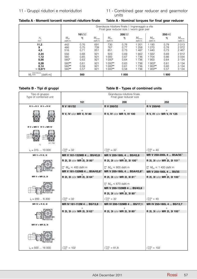
57A04 December 2011
11 - Gruppi riduttori e motoriduttori 11 - Combined gear reducer and gearmotor units
Tabella A - Momenti torcenti nominali riduttore finale Table A - Nominal torques for final gear reducer
Tabella B - Tipi di gruppi Table B - Types of combined units
Grandezza riduttore finale / i ingranaggio a viteFinal gear reducer size / i worm gear pair
161/32 200/32 250/40 n2 MN2 � M2max MN2 � M2max MN2 � M2max min-1 daN m daN m daN m daN m daN m daN m
11,2 442 0,76 691 730 0,78 1 201 1 190 0,79 2 013 9 466 0,75 739 767 0,77 1 258 1 270 0,78 2 072 4,5 516 0,71 851 851 0,73 1 487 1 440 0,73 2 467 2,24 556 0,68 921 923 0,69 1 662 1 562 0,69 2 812 1,12 560 0,65 921 1 000 0,67 1 736 1 704 0,66 3 034 0,56 560* 0,63 921 1 000* 0,64 1 736 1 900 0,64 3 134 0,28 560** 0,61 921 1 000** 0,63 1 736 1 900* 0,61 3 134 0,14 560** 0,59 921 1 000** 0,61 1 736 1 900** 0,60 3 134 � 0,071 560** 0,57 921 1 000** 0,58 1 736 1 900** 0,57 3 134
M2 GrandezzaSize [daN m] 560 1 000 1 900
Tipo di gruppo Grandezza riduttore finale Type of combined unit Final gear reducer size
161 200 250 R V + R V R V + R IV R V 161/32 R V 200/32 R V 250/40 + + + R V, IV o/or MR V, IV 80 R V, IV o/or MR V, IV 100 R V, IV o/or MR V, IV 125
R V + MR V R V + MR IV
1)
iN ≈ 315 ... 10 000 i finalefinal = 32 i finale
final = 32 i finalefinal = 40
MR V + R 2I, 3I MR V 161-132MB 4 ... B5/43,8 MR V 200-180L 4 ... B5/43,8 MR V 250-200L 4 ... B5A/357)
+ + + R 2I, 3I o/or MR 2I, 3I 804)
R 2I, 3I o/or MR 2I, 3I 1004) R 2I, 3I o/or MR 2I, 3I 1014)
perfor MN2 � 400 daN m
perfor MN2 � 800 daN m
perfor MN2 � 1 400 daN m
MR V 161-132MB 4 ... B5A/43,85) MR V 200-180L 4 ... B5A/43,86)
MR V 250-180L 4 ... B5/35 + + MR V + MR 2I, 3I R 2I, 3I o/or MR 2I, 3I 644)
R 2I, 3I o/or MR 2I, 3I 814) R 2I, 3I o/or MR 2I, 3I 1004)
perfor MN2 � 670 daN m
MR V 200-132MB 4 ... B5/43,8 + R 2I, 3I o/or MR 2I, 3I 804)
iN ≈ 200 ... 6 300 i finalefinal = 32 i finale
final = 32 i finalefinal = 40
MR IV + R 2I, 3I MR IV 161-112M 4 ... B5/13,8 MR IV 200-132MB 4 ... B5/17,1 MR IV 250-180L 4 ... B5/13,7 + + + R 2I, 3I o/or MR 2I, 3I 634)
R 2I, 3I o/or MR 2I, 3I 804) R 2I, 3I o/or MR 2I, 3I 1004)
MR IV + MR 2I, 3I
iN ≈ 500 ... 16 000 i finalefinal = 102 i finale
final = 81,8 i finalefinal = 102
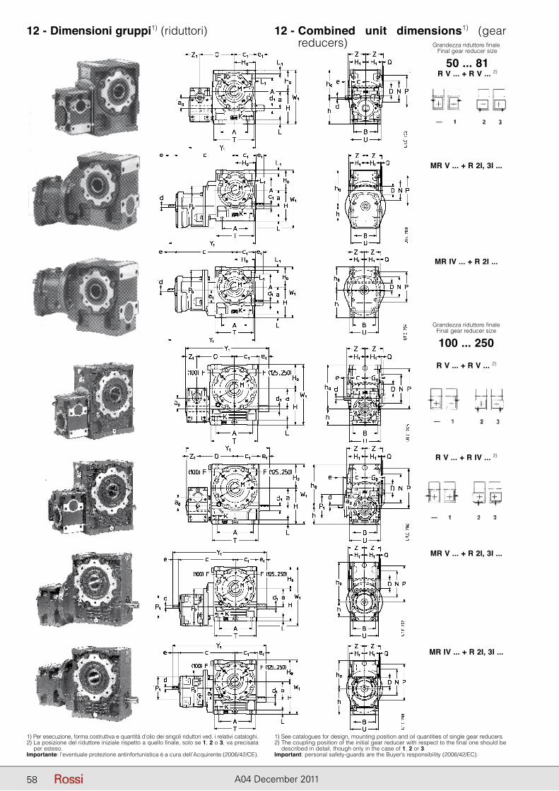
58 A04 December 2011
12 - Dimensioni gruppi1) (riduttori) 12 - Combined unit dimensions1) (gear re ducers) Grandezza riduttore finale
Final gear reducer size
50 ... 81
Grandezza riduttore finaleFinal gear reducer size
100 ... 250
R V ... + R V ... 2)
MR V ... + R 2I, 3I ...
MR IV ... + R 2I ...
R V ... + R V ... 2)
R V ... + R IV ... 2)
MR V ... + R 2I, 3I ...
MR IV ... + R 2I, 3I ...
1) Per esecuzione, forma costruttiva e quantità d’olio dei singoli riduttori ved. i relativi cataloghi.2) La posizione del riduttore iniziale rispetto a quello finale, solo se 1, 2 o 3, va precisata
per esteso.Importante: l’eventuale protezione antinfortunistica è a cura dell’Acquirente (2006/42/CE).
1) See catalogues for design, mounting position and oil quantities of single gear reducers.2) The coupling position of the initial gear reducer with respect to the final one should be
described in detail, though only in the case of 1, 2 or 3.Important: personal safety-guards are the Buyer’s responsibility (2006/42/EC).
58
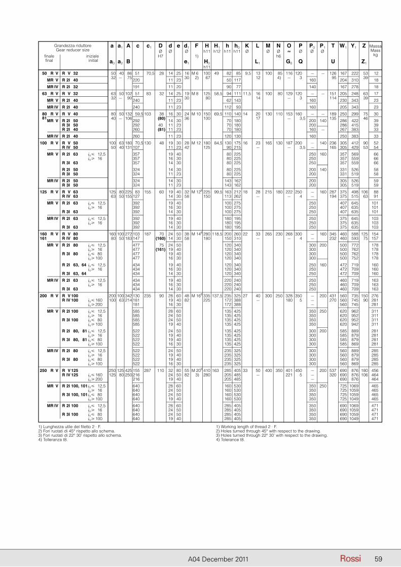
59A04 December 2011
Grandezza riduttoreGear reducer size
finale iniziale final initial
a a1 A c c1 D d e d1 F H H1 h h0 K L M N O P P0 P1 T W1 Y1 Z Massa Ø Ø Ø h11 h12 h11 h11 Ø Ø Ø ≈ Ø Ø Ø Mass H7 1) h6 kg
a0 a2 B e1 H0 L1 G0 Q U Z1 h11
50 R V R V 32 50 40 86 51 70,5 28 14 25 16 M 6 100 49 82 85 9,5 13 100 85 116 120 – – 126 167 222 53 12
MR V R 2I 40 32 – 75 220 11 23 30 2) 67 50 117 12 4) – 3 160 95 204 310 39 18
MR IV R 2I 32 191 11 20 90 77 140 167 278 18
63 R V R V 32 63 50 102 51 83 32 14 25 19 M 8 125 58,5 94 111 11,5 16 100 80 129 120 – – 151 205 248 63 17
MR V R 2I 40 32 – 90 240 11 23 30 80 62 143 14 – 3 160 114 230 343 39 23
MR IV R 2I 40 240 11 23 112 93 160 205 343 23
80 R V R V 40 80 50 132 59,5 103 38 16 30 24 M 10 150 69,5 110 140 14 20 130 110 153 160 – – 189 250 299 75 30
81 MR V R 2I 50 40 – 106 292 (80) 14 30 36 100 70 180 17 – 3,5 200 140 135 286 422 46 39
R 3I 50 292 40 11 23 70 180 200 286 415 39 R 2I 40 260 (81) 11 23 70 180 160 – 267 383 33
MR IV R 2I 40 260 11 23 120 130 160 250 383 33
100 R V R V 50 100 63 180 70,5 130 48 19 30 28 M 12 180 84,5 130 175 16 23 165 130 187 200 – 140 236 305 412 90 52 R IV 50 50 40 131 107 11 23 42 125 90 215 – – 3,5 – 165 305 429 53 54
MR V R 2I 63 iN � 12,5 357 19 40 80 225 250 160 357 569 66 iN � 16 357 16 30 80 225 250 357 559 66 R 3I 63 357 14 30 80 225 250 357 559 66
R 2I 50 324 14 30 80 225 200 140 331 526 58 R 3I 50 324 11 23 80 225 200 331 519 58
MR IV R 2I 50 324 14 30 143 162 200 305 526 59 R 3I 50 324 11 23 143 162 200 305 519 59
125 R V R V 63 125 80 225 83 155 60 19 40 32 M 128 225 99,5 163 212 18 28 215 180 222 250 – 160 287 375 498 106 88 R IV 63 63 50 155 127 14 30 58 150 113 262 – – 4 – 194 375 515 63 91
MR V R 2I 63 iN � 12,5 392 19 40 100 275 250 407 645 101 iN � 16 392 16 30 100 275 250 407 635 101 R 3I 63 392 14 30 100 275 250 407 635 101
MR IV R 2I 63 iN � 12,5 392 19 40 180 195 250 375 645 103 iN � 16 392 16 30 180 195 250 375 635 103 R 3I 63 392 14 30 180 195 250 375 635 103
160 R V R V 80 160 100 272 103 187 70 24 50 38 M 148 280 118,5 200 260 22 33 265 230 268 300 – 160 345 460 588 125 154 161 R IV 80 80 50 183 147 (160) 14 30 58 180 150 310 – – 4 – 232 460 593 75 157
MR V R 2I 80 iN � 12,5 477 75 24 50 120 340 300 200 500 772 178 iN � 16 477 (161) 19 40 120 340 300 500 762 178 R 3I 80 iN � 80 477 19 40 120 340 300 500 762 178 iN � 100 477 16 30 120 340 300 500 752 178
R 2I 63, 64 iN � 12,5 434 19 40 120 340 250 160 472 719 160 iN � 16 434 16 30 120 340 250 472 709 160 R 3I 63, 64 434 14 30 120 340 250 472 709 160
MR IV R 2I 63 iN � 12,5 434 19 40 220 240 250 460 719 163 iN � 16 434 16 30 220 240 250 460 709 163 R 3I 63 434 14 30 220 240 250 460 709 163
200 R V R V 100 200 100 342 130 235 90 28 60 48 M 168 335 137,5 235 325 27 40 300 250 328 350 – 200 431 560 735 150 276 R IV 100 iN � 160 100 63 214 181 19 40 82 225 172 388 – 180 5 – 270 560 745 90 281 iN � 200 181 16 30 172 388 – 560 745 281
MR V R 2I 100 iN � 12,5 585 28 60 135 425 350 250 620 962 311 iN � 16 585 24 50 135 425 350 620 952 311 R 3I 100 iN � 80 585 24 50 135 425 350 620 952 311 iN � 100 585 19 40 135 425 350 620 942 311
R 2I 80, 81 iN � 12,5 522 24 50 135 425 300 200 585 889 281 iN � 16 522 19 40 135 425 300 585 879 281 R 3I 80, 81 iN � 80 522 19 40 135 425 300 585 879 281 iN � 100 522 16 30 135 425 300 585 869 281
MR IV R 2I 80 iN � 12,5 522 24 50 235 325 300 560 889 285 iN � 16 522 19 40 235 325 300 560 879 285 R 3I 80 iN � 80 522 19 40 235 325 300 560 879 285 iN � 100 522 16 30 235 325 300 560 869 285
250 R V R V 125 250 125 425 155 287 110 32 80 55 M 208 410 163,5 285 405 33 50 400 350 401 450 – 200 537 690 876 180 456 R IV 125 iN � 160 125 80 250 216 24 50 82 3) 280 205 485 – 221 5 – 320 690 876 106 464 iN � 200 216 19 40 205 485 – 690 876 464
MR V R 2I 100, 101 iN � 12,5 640 28 60 160 530 350 250 725 1069 465 iN � 16 640 24 50 160 530 350 725 1059 465 R 3I 100, 101 iN � 80 640 24 50 160 530 350 725 1059 465 iN � 100 640 19 40 160 530 350 725 1049 465
MR IV R 2I 100 iN � 12,5 640 28 60 285 405 350 690 1069 471 iN � 16 640 24 50 285 405 350 690 1059 471 R 3I 100 iN � 80 640 24 50 285 405 350 690 1059 471 iN � 100 640 19 40 285 405 350 690 1049 471
1) Lunghezza utile del filetto 2 · F.2) Fori ruotati di 45° rispetto allo schema.3) Fori ruotati di 22° 30’ rispetto allo schema.4) Tolleranza t8.
1) Working length of thread 2 · F.2) Holes turned through 45° with respect to the drawing.3) Holes turned through 22° 30’ with respect to the drawing.4) Tolerance t8.
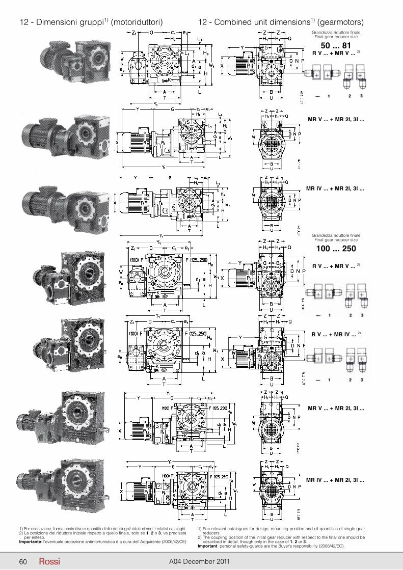
60 A04 December 2011
12 - Dimensioni gruppi1) (motoriduttori)
1) Per esecuzione, forma costruttiva e quantità d’olio dei singoli riduttori ved. i relativi cataloghi.2) La posizione del riduttore iniziale rispetto a quello finale, solo se 1, 2 o 3, va precisata
per esteso.Importante: l’eventuale protezione antinfortunistica è a cura dell’Acquirente (2006/42/CE)
1) See relevant catalogues for design, mounting position and oil quantities of single gear reducers.
2) The coupling position of the initial gear reducer with respect to the final one should be described in detail, though only in the case of 1, 2 or 3.
Important: personal safety-guards are the Buyer’s responsibility (2006/42/EC).
MR V ... + MR 2I, 3I ...
MR IV ... + MR 2I, 3I ...
R V ... + MR IV ... 2)
MR V ... + MR 2I, 3I ...
MR IV ... + MR 2I, 3I ...
Grandezza riduttore finaleFinal gear reducer size
100 ... 250
R V ... + MR V ... 2)
12 - Combined unit dimensions1) (gearmotors)Grandezza riduttore finale
Final gear reducer size
50 ... 81R V ... + MR V ... 2)
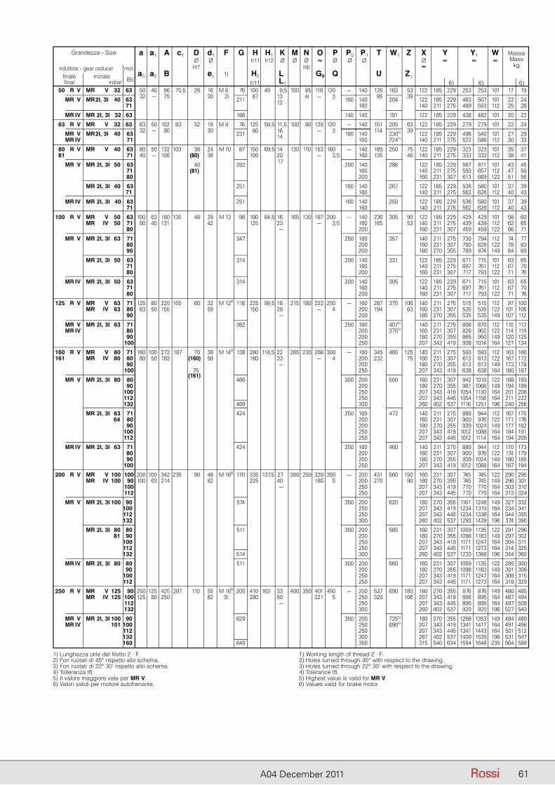
61A04 December 2011
Grandezza - Size
riduttore - gear reducer mot. finale iniziale B5 final initial
a a1 A c1 D d1 F G H H1 K M N O P P0 P1 T W1 Z X Y Y1 W Massa Ø Ø h11 h12 Ø Ø Ø ≈ Ø Ø Ø Ø ≈ ≈ ≈ Mass H7 h6 ≈ kg
a0 a2 B e1 1) H0 L1 G0 Q U Z1 h11 L1 6) 6) 6)
50 R V MR V 32 63 50 40 86 70,5 28 16 M 648 76 100 49,5 9,5 100 85 116 120,5 – 140 126 1835) 53 122 185 229 253 253 101 17 19
MR V MR 2I, 3I 40 63 32 – 75 30 2)48 211 67 ,5 13,5 4) – 3,5 160 140 95 2045) 39 122 185 229 463 507 101 22 24 71 12,5 160 5) 140 211 275 489 553 112 25 28
MR IV MR 2I, 3I 32 63 186 140 140 1915) 5) 122 185 229 438 482 101 20 22
63 R V MR V 32 63 63 50 102 83,5 32 19 M 848 76 125 58,5 11,5 100 80 129 120,5 – 140 151 2055) 63 122 185 229 279 279 101 22 24
MR V MR 2I, 3I 40 63 32 – 90 30 48 231 80 ,5 16,5 – 3,5 160 140 114 2305) 39 122 185 229 496 540 101 27 29 MR IV 71 14,5 160 2245) 5) 140 211 275 522 586 112 30 33
80 R V MR V 40 63 80 50 132 103,5 38 24 M 108 87 150 69,5 14,5 130 110 153 160,5 – 140 189 2505) 75 122 185 229 323 323 101 35 37 81 71 40 – 106 (80) 36 48 100 ,5 20,5 – 3,5 160 135 5) 46 140 211 275 333 333 112 38 41
MR V MR 2I, 3I 50 63 40 282 17,5 200 140 2865) 5) 122 185 229 567 611 101 43 45 71 (81) 48 ,5 ,5 160 5) 140 211 275 593 657 112 47 50 80 48 ,5 ,5 200 5) 160 231 307 613 689 122 51 56
MR 2I, 3I 40 63 251 ,5 160 140 2675) 5) 122 185 229 536 580 101 37 39 71 48 ,5 ,5 160 5) 140 211 275 562 626 112 40 43
MR IV MR 2I, 3I 40 63 251 ,5 160 140 2505) 5) 122 185 229 536 580 101 37 39 71 48 ,5 ,5 160 5) 140 211 275 562 626 112 40 43
100 R V MR V 50 63 100 63 180 130,5 48 28 M 128 98 180 84,5 16,5 165 130 187 200,5 – 140 236 3055) 90 122 185 229 429 429 101 58 60 MR IV 50 71 50 40 131 42 48 125 ,5 23,5 – 3,5 160 165 5) 53 140 211 275 439 439 112 62 65 80 48 ,5 ,–5 200 5) 160 231 307 459 459 122 66 71
MR V MR 2I, 3I 63 71 347 ,5 250 160 3575) 5) 140 211 275 730 794 112 74 77 80 48 ,5 ,5 200 5) 160 231 307 750 826 122 78 83 90 48 ,5 ,5 200 5) 180 270 355 789 874 149 84 89
MR 2I, 3I 50 63 314 ,5 200 140 3315) 5) 122 185 229 671 715 101 63 65 71 48 ,5 ,5 160 5) 140 211 275 697 761 112 67 70 80 48 ,5 ,5 200 5) 160 231 307 717 793 122 71 76
MR IV MR 2I, 3I 50 63 314 ,5 200 140 3055) 5) 122 185 229 671 715 101 63 65 71 48 ,5 ,5 160 5) 140 211 275 697 761 112 67 70 80 48 ,5 ,5 200 5) 160 231 307 717 793 122 71 76
125 R V MR V 63 71 125 80 225 155,5 60 32 M 128 118 225 99,5 18,5 215 180 222 250,5 – 160 287 3755) 106 140 211 275 515 515 112 97 100 MR IV 63 80 63 50 155 58 48 150 ,5 28,5 – 4,5 200 194 5) 63 160 231 307 535 535 122 101 106 90 48 ,5 ,–5 200 5) 180 270 355 535 535 149 107 112
MR V MR 2I, 3I 63 71 382 ,5 250 160 4075) 5) 140 211 275 806 870 112 110 113 MR IV 80 48 ,5 ,5 200 3755) 160 231 307 826 902 122 114 119 90 48 ,5 ,5 200 5) 180 270 355 865 950 149 120 125 100 48 ,5 ,5 250 5) 207 343 419 938 1014 164 127 134
160 R V MR V 80 71 160 100 272 187,5 70 38 M 148 138 280 118,5 22,5 265 230 268 300,5 – 160 345 4605) 125 140 211 275 593 593 112 163 166 161 MR IV 80 80 80 50 183 (160) 58 48 180 ,5 33,5 – 4,5 200 232 5) 75 160 231 307 613 613 122 167 172 90 48 ,5 ,–5 200 5) 180 270 355 613 613 149 173 178 100 75 48 ,5 ,5 250 5) 207 343 419 638 638 164 180 187
MR V MR 2I, 3I 80 80 (161)
466 ,5 300 200 5005) 5) 160 231 307 942 1018 122 188 193 90 48 ,5 ,5 200 5) 180 270 355 981 1066 149 194 199 100 ,5 250 5) 5) 207 343 419 1054 1130 164 201 208 112 ,5 250 5) 5) 207 343 445 1054 1156 164 211 222 132 469 ,5 300 5) 5) 260 402 537 1116 1251 196 240 256
MR 2I, 3I 63 71 424 ,5 250 160 4725) 5) 140 211 275 880 944 112 167 170 64 80 ,5 200 5) 5) 160 231 307 900 976 122 171 176 90 ,5 200 5) 5) 180 270 355 939 1024 149 177 182 100 ,5 250 5) 5) 207 343 419 1012 1088 164 184 191 112 ,5 250 5) 5) 207 343 445 1012 1114 164 194 205
MR IV MR 2I, 3I 63 71 424 ,5 250 160 4605) 5) 140 211 275 880 944 112 170 173 80 ,5 200 5) 5) 160 231 307 900 976 122 174 179 90 ,5 200 5) 5) 180 270 355 939 1024 149 180 185 100 ,5 250 5) 5) 207 343 419 1012 1088 164 187 194
200 R V MR V 100 100 200 100 342 235,5 90 48 M 168 170 335 137,5 27,5 300 250 328 350,5 – 200 431 5605) 150 160 231 307 745 745 122 290 295 MR IV 100 90 100 63 214 82 48 225 ,5 40,5 180 5,5 200 270 5) 90 180 270 355 745 745 149 296 301 100 48 ,5 ,–5 250 5) 207 343 419 770 770 164 303 310 112 48 ,5 ,5 250 5) 207 343 445 770 770 164 313 324
MR V MR 2I, 3I 100 90 574 ,5 350 200 6205) 5) 180 270 355 1161 1246 149 327 332 100 ,5 250 5) 5) 207 343 419 1234 1310 164 334 341 112 ,5 250 5) 5) 207 343 445 1234 1336 164 344 355 132 ,5 300 5) 5) 260 402 537 1293 1428 196 374 390
MR 2I, 3I 80 80 511 ,5 300 200 5855) 5) 160 231 307 1059 1135 122 291 296 81 90 ,5 200 5) 5) 180 270 355 1098 1183 149 297 302 100 ,5 250 5) 5) 207 343 419 1171 1247 164 304 311 112 ,5 250 5) 5) 207 343 445 1171 1273 164 314 325 132 514 ,5 300 5) 5) 260 402 537 1233 1368 196 344 360
MR IV MR 2I, 3I 80 80 511 ,5 300 200 5605) 5) 160 231 307 1059 1135 122 295 300 90 ,5 200 5) 5) 180 270 355 1098 1183 149 301 306 100 ,5 250 5) 5) 207 343 419 1171 1247 164 308 315 112 ,5 250 5) 5) 207 343 445 1171 1273 164 318 329
250 R V MR V 125 90 250 125 425 287,5 110 55 M 168 205 410 163,5 33,5 400 350 401 450,5 – 200 537 6905) 180 180 270 355 876 876 149 480 485 MR IV 125 100 125 80 250 82 3) 280 ,5 50,5 221 5,5 250 320 5) 106 207 343 419 895 895 164 487 494 112 48 ,5 ,–5 250 5) 207 343 445 895 895 164 497 508 132 48 ,5 ,5 300 5) 260 402 537 920 920 196 527 543
MR V MR 2I, 3I 100 90 629 ,5 350 200 7255) 5) 180 270 355 1268 1353 149 484 489 MR IV 101 100 ,5 250 6905) 5) 207 343 419 1341 1417 164 491 498 112 ,5 250 5) 5) 207 343 445 1341 1443 164 501 512 132 ,5 300 5) 5) 267 402 537 1400 1535 196 531 547 160 645 ,5 350 5) 5) 315 540 634 1554 1648 235 564 588
1) Lunghezza utile del filetto 2 · F.2) Fori ruotati di 45° rispetto allo schema.3) Fori ruotati di 22° 30’ rispetto allo schema.4) Tolleranza t8.5) Il valore maggiore vale per MR V.6) Valori validi per motore autofrenante.
1) Working length of thread 2 · F.2) Holes turned through 45° with respect to the drawing.3) Holes turned through 22° 30’ with respect to the drawing.4) Tolerance t8.5) Highest value is valid for MR V.6) Values valid for brake motor.
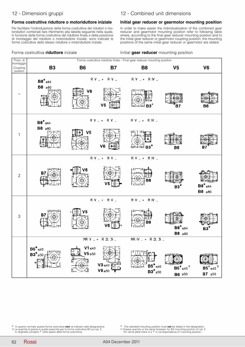
62 A04 December 2011
12 - Dimensioni gruppi 12 - Combined unit dimensions
* In quanto normale questa forma costruttiva non va indicata nella designazione.1) La quantità di grasso è quella prescritta per la forma costruttiva B3 sul cat. E. In targhetta compare * nello spazio della forma costruttiva.
* This standard mounting position must not be stated in the designation.1) Grease quantity is the same foreseen for B3 mounting position of cat. E. On name plate there is a * in correspondence of mounting position.
Forma costruttiva riduttore o motoriduttore inizialePer facilitare l’individuazione della forma costruttiva dei riduttori o mo-toriduttori combinati fare riferimento alla tabella seguente nella quale, in funzione della forma costruttiva del riduttore finale e della posizione di montaggio del riduttore o motoriduttore iniziale, sono indicate le forme costruttive dello stesso riduttore o motoriduttore iniziale.
Forma costruttiva riduttore iniziale
Initial gear reducer or gearmotor mounting positionIn order to make easier the individualization of the combined gear reducer and gearmotor mounting position refer to following table where, according to the final gear reducer mounting position and to the initial gear reducer or gearmotor coupling position, the mounting positions of the same initial gear reducer or gearmotor are stated.
Initial gear reducer mounting position
Posiz. dimontaggioCouplingposition
–
1
2
3
Forma costruttiva riduttore finale - Final gear reducer mounting position
B3 B6 B7 B8 V5 V6
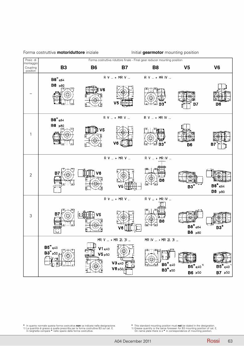
63A04 December 2011
* In quanto normale questa forma costruttiva non va indicata nella designazione.1) La quantità di grasso è quella prescritta per la forma costruttiva B3 sul cat. E. In targhetta compare * nello spazio della forma costruttiva.
* This standard mounting position must not be stated in the designation.1) Grease quantity is the same foreseen for B3 mounting position of cat. E. On name plate there is a * in correspondence of mounting position.
Forma costruttiva motoriduttore iniziale Initial gearmotor mounting position
Posiz. dimontaggioCouplingposition
–
1
2
3
Forma costruttiva riduttore finale - Final gear reducer mounting position
B3 B6 B7 B8 V5 V6
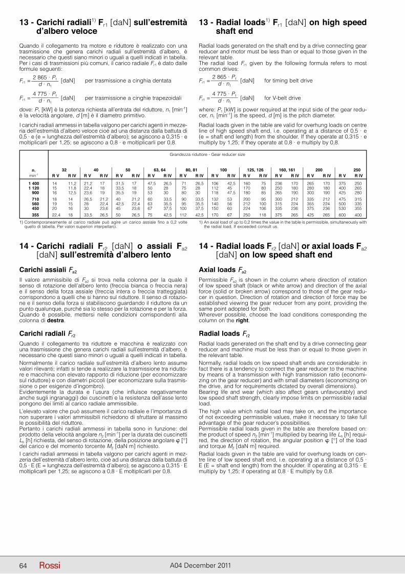
64 A04 December 2011
13 - Carichi radiali1) Fr1 [daN] sull’estremità d’albero veloce
13 - Radial loads1) Fr1 [daN] on high speed shaft end
Quando il collegamento tra motore e riduttore è realizzato con una trasmissione che genera carichi radiali sull’estremità d’albero, è ne cessario che questi siano minori o uguali a quelli indicati in tabella.Per i casi di trasmissioni più comuni, il carico radiale Fr1 è dato dalle formule seguenti:
Fr1 =2 865 · P1
d · n1 [daN] per trasmissione a cinghia dentata
Fr1 =4 775 · P1
d · n1 [daN] per trasmissione a cinghie trapezoidali
dove: P1 [kW] è la potenza richiesta all’entrata del riduttore, n1 [min-1] è la velocità angolare, d [m] è il diametro primitivo.
I carichi radiali ammessi in tabella valgono per carichi agenti in mezze-ria dell’estremità d’albero veloce cioè ad una distanza dalla battuta di 0,5 · e (e = lunghezza dell’estremità d’albero); se agiscono a 0,315 · e moltiplicarli per 1,25; se agiscono a 0,8 · e moltiplicarli per 0,8.
Radial loads generated on the shaft end by a drive connecting gear reducer and motor must be less than or equal to those given in the relevant table.The radial load Fr1 given by the following formula refers to most com mon drives:
Fr1 =2 865 · P1
d · n1 [daN] for timing belt drive
Fr1 =4 775 · P1
d · n1 [daN] for V-belt drive
where: P1 [kW] is power required at the input side of the gear redu-cer, n1 [min-1] is the speed, d [m] is the pitch diameter.
Radial loads given in the table are valid for overhung loads on centre line of high speed shaft end, i.e. operating at a distance of 0,5 · e (e = shaft end length) from the shoulder. If they operate at 0,315 · e multiply by 1,25; if they operate at 0,8 · e multiply by 0,8.
14 - Carichi radiali Fr2 [daN] o assiali Fa2 [daN] sull’estremità d’albero lento
Carichi assiali Fa2
Il valore ammissibile di Fa2 si trova nella colonna per la quale il senso di rotazione dell’albero lento (freccia bianca o freccia nera) e il sen so della forza assiale (freccia intera o freccia tratteggiata) corrispondono a quelli che si hanno sul riduttore. Il senso di rotazio-ne e il senso della forza si stabiliscono guardando il riduttore da un punto qualunque, purché sia lo stesso per la rotazione e per la forza.Quando è possibile, mettersi nelle condizioni corrispondenti alla colonna di destra.
Carichi radiali Fr2
Quando il collegamento tra riduttore e macchina è realizzato con una trasmissione che genera carichi radiali sull’estremità d’albero, è ne cessario che questi siano minori o uguali a quelli indicati in tabella.Normalmente il carico radiale sull’estremità d’albero lento assume valori rilevanti; infatti si tende a realizzare la trasmissione tra ridutto-re e macchina con elevato rapporto di riduzione (per economizzare sul riduttore) e con diametri piccoli (per economizzare sulla trasmis-sione o per esigenze d’ingombro).Evidentemente la durata e l’usura (che influisce negativamente an che sugli ingranaggi) dei cuscinetti e la resistenza dell’asse lento pongono dei limiti al carico radiale ammissibile.L’elevato valore che può assumere il carico radiale e l’importanza di non superare i valori ammissibili richiedono di sfruttare al massimo le possibilità del riduttore.Pertanto i carichi radiali ammessi in tabella sono in funzione: del prodotto della velocità angolare n2 [min-1] per la durata dei cuscinetti Lh [h] richiesta, del senso di rotazione, della posizione angolare � [°] del carico e del momento torcente M2 [daN m] richiesto.I carichi radiali ammessi in tabella valgono per carichi agenti in mez-zeria dell’estremità d’albero lento, cioè ad una distanza dalla battuta di 0,5 · E (E = lunghezza dell’estremità d’albero); se agiscono a 0,315 · E moltiplicarli per 1,25; se agiscono a 0,8 · E moltiplicarli per 0,8.
14 - Radial loads Fr2 [daN] or axial loads Fa2 [daN] on low speed shaft end
Axial loads Fa2
Permissible Fa2 is shown in the column where direction of rotation of low speed shaft (black or white arrow) and direction of the axial force (solid or broken arrow) correspond to those of the gear redu-cer in question. Direction of rotation and direction of force may be established viewing the gear reducer from any point, providing the same point adopted for both.Wherever possible, choose the load conditions corresponding the column on the right.
Radial loads Fr2
Radial loads generated on the shaft end by a drive connecting gear reducer and machine must be less than or equal to those given in the relevant table.Normally, radial loads on low speed shaft ends are considerable: in fact there is a tendency to connect the gear reducer to the machine by means of a transmission with high transmission ratio (economi-zing on the gear reducer) and with small diameters (economizing on the drive, and for requirements dictated by overall dimensions).Bearing life and wear (which also affect gears unfavourably) and low speed shaft strength, clearly impose limits on permissible radial load.The high value which radial load may take on, and the importance of not exceeding permissible values, make it necessary to take full advantage of the gear reducer’s possibilities.Permissible radial loads given in the table are therefore based on: the product of speed n2 [min-1] multiplied by bearing life Lh [h] requi-red, the direction of rotation, the angular position � [°] of the load and torque M2 [daN m] required.Radial loads given in the table are valid for overhung loads on cen-tre line of low speed shaft end, i.e. operating at a distance of 0,5 · E (E = shaft end length) from the shoulder. If operating at 0,315 · Emultiply by 1,25; if operating at 0,8 · E multiply by 0,8.
1) Contemporaneamente al carico radiale può agire un carico assiale fino a 0,2 volte quello di tabella. Per valori superiori interpellarci.
1) An axial load of up to 0,2 times the value in the table is permissible, simultaneously with the radial load. If exceeded consult us.
n1
min-1
Grandezza riduttore - Gear reducer size
32 40 50 63, 64 80, 81 100 125, 126 160, 161 200 250 R V R IV R V R IV R V R IV R V R IV R V R IV R V R IV R V R IV R V R IV R V R IV R V R IV
1 400 14 11,2 21,2 17 31,5 17 47,5 26,5 71 26,5 106 42,5 160 75 236 170 265 170 375 250 1 120 15 11,8 22,4 18 33,5 18 50 28 75 28 112 45 170 80 250 180 280 180 400 265 900 16 12,5 23,6 19 35,5 19 53 30 80 30 118 47,5 180 85 265 190 300 190 425 280
710 18 14 26,5 21,2 40 21,2 60 33,5 90 33,5 132 53 200 95 300 212 335 212 475 315 560 19 15 28 22,4 42,5 22,4 63 35,5 95 35,5 140 56 212 100 315 224 355 224 500 335 450 20 16 30 23,6 45 23,6 67 37,5 100 37,5 150 60 224 106 335 236 375 236 530 355
355 22,4 18 33,5 26,5 50 26,5 75 42,5 112 42,5 170 67 250 118 375 265 425 265 600 400
64
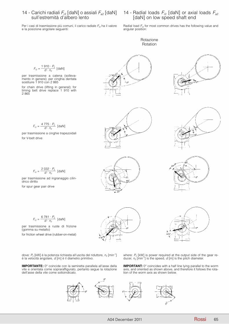
65A04 December 2011
14 - Carichi radiali Fr2 [daN] o assiali Fa2 [daN] sull’estremità d’albero lento
14 - Radial loads Fr2 [daN] or axial loads Fa2 [daN] on low speed shaft end
Per i casi di trasmissione più comuni, il carico radiale Fr2 ha il valore e la posizione angolare seguenti:
Radial load Fr2 for most common drives has the following value and angular position:
dove: P2 [kW] è la potenza richiesta all’uscita del riduttore, n2 [min-1] è la velocità angolare, d [m] è il diametro primitivo.
IMPORTANTE: 0° coincide con la semiretta parallela all’asse della vite e orientata come sopraraffigurato, pertanto segue la rotazione dell’asse della vite come sottoindicato.
where: P2 [kW] is power required at the output side of the gear re-ducer, n2 [min-1] is the speed, d [m] is the pitch diameter.
IMPORTANT: 0° coincides with a half line lying parallel to the worm axis, and oriented as shown above, and therefore it follows the rota-tion of the worm axis as shown below.
Fr2 = 1 910 · P2
d · n2 [daN]
per trasmissione a catena (solleva-mento in genere); per cinghia dentata sostituire 1 910 con 2 865
for chain drive (lifting in general); for timing belt drive replace 1 910 with2 865
Fr2 = 4 775 · P2
d · n2 [daN]
per trasmissione a cinghie trapezoidali
for V-belt drive
Fr2 = 2 032 · P2
d · n2 [daN]
per trasmissione ad ingranaggio cilin-drico diritto
for spur gear pair drive
Fr2 = 6 781 · P2
d · n2 [daN]
per trasmissione a ruote di frizione (gomma su metallo)
for friction wheel drive (rubber-on-metal)
RotazioneRotation
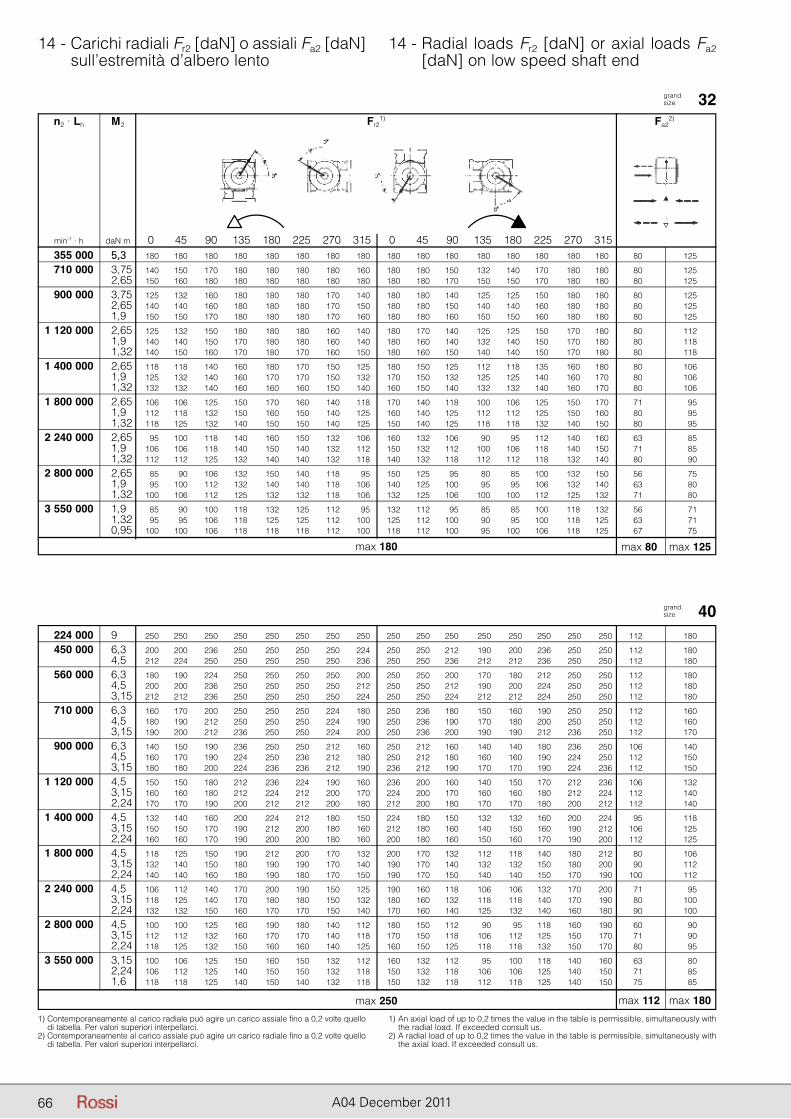
66 A04 December 2011
14 - Carichi radiali Fr2 [daN] o assiali Fa2 [daN] sull’estremità d’albero lento
14 - Radial loads Fr2 [daN] or axial loads Fa2 [daN] on low speed shaft end
grand. size 32
1) Contemporaneamente al carico radiale può agire un carico assiale fino a 0,2 volte quello di tabella. Per valori superiori interpellarci.
2) Contemporaneamente al carico assiale può agire un carico radiale fino a 0,2 volte quello di tabella. Per valori superiori interpellarci.
1) An axial load of up to 0,2 times the value in the table is permissible, simultaneously with the radial load. If exceeded consult us.
2) A radial load of up to 0,2 times the value in the table is permissible, simultaneously with the axial load. If exceeded consult us.
n2 · Lh M2 Fr21) Fa2
2)
min-1 · h daN m 0 45 90 135 180 225 270 315 0 45 90 135 180 225 270 315
grand. size 40
max 80 max 125max 180
max 112 max 180max 250
355 000 5,3 180 180 180 180 180 180 180 180 180 180 180 180 180 180 180 180 80 125
710 000 3,75 140 150 170 180 180 180 180 160 180 180 150 132 140 170 180 180 80 125 2,65 150 160 180 180 180 180 180 180 180 180 170 150 150 170 180 180 80 125
900 000 3,75 125 132 160 180 180 180 170 140 180 180 140 125 125 150 180 180 80 125 2,65 140 140 160 180 180 180 170 150 180 180 150 140 140 160 180 180 80 125 1,9 150 150 170 180 180 180 170 160 180 180 160 150 150 160 180 180 80 125
1 120 000 2,65 125 132 150 180 180 180 160 140 180 170 140 125 125 150 170 180 80 112 1,9 140 140 150 170 180 180 160 140 180 160 140 132 140 150 170 180 80 118 1,32 140 150 160 170 180 170 160 150 180 160 150 140 140 150 170 180 80 118
1 400 000 2,65 118 118 140 160 180 170 150 125 180 150 125 112 118 135 160 180 80 106 1,9 125 132 140 160 170 170 150 132 170 150 132 125 125 140 160 170 80 106 1,32 132 132 140 160 160 160 150 140 160 150 140 132 132 140 160 170 80 106
1 800 000 2,65 106 106 125 150 170 160 140 118 170 140 118 100 106 125 150 170 71 95 1,9 112 118 132 150 160 150 140 125 160 140 125 112 112 125 150 160 80 95 1,32 118 125 132 140 150 150 140 125 150 140 125 118 118 132 140 150 80 95
2 240 000 2,65 95 100 118 140 160 150 132 106 160 132 106 90 95 112 140 160 63 85 1,9 106 106 118 140 150 140 132 112 150 132 112 100 106 118 140 150 71 85 1,32 112 112 125 132 140 140 132 118 140 132 118 112 112 118 132 140 80 90
2 800 000 2,65 85 90 106 132 150 140 118 95 150 125 95 80 85 100 132 150 56 75 1,9 95 100 112 132 140 140 118 106 140 125 100 95 95 106 132 140 63 80 1,32 100 106 112 125 132 132 118 106 132 125 106 100 100 112 125 132 71 80
3 550 000 1,9 85 90 100 118 132 125 112 95 132 112 95 85 85 100 118 132 56 71 1,32 95 95 106 118 125 125 112 100 125 112 100 90 95 100 118 125 63 71 0,95 100 100 106 118 118 118 112 100 118 112 100 95 100 106 118 125 67 75
224 000 9 250 250 250 250 250 250 250 250 250 250 250 250 250 250 250 250 112 180
450 000 6,3 200 200 236 250 250 250 250 224 250 250 212 190 200 236 250 250 112 180 4,5 212 224 250 250 250 250 250 236 250 250 236 212 212 236 250 250 112 180
560 000 6,3 180 190 224 250 250 250 250 200 250 250 200 170 180 212 250 250 112 180 4,5 200 200 236 250 250 250 250 212 250 250 212 190 200 224 250 250 112 180 3,15 212 212 236 250 250 250 250 224 250 250 224 212 212 224 250 250 112 180
710 000 6,3 160 170 200 250 250 250 224 180 250 236 180 150 160 190 250 250 112 160 4,5 180 190 212 250 250 250 224 190 250 236 190 170 180 200 250 250 112 160 3,15 190 200 212 236 250 250 224 200 250 236 200 190 190 212 236 250 112 170
900 000 6,3 140 150 190 236 250 250 212 160 250 212 160 140 140 180 236 250 106 140 4,5 160 170 190 224 250 236 212 180 250 212 180 160 160 190 224 250 112 150 3,15 180 180 200 224 236 236 212 190 236 212 190 170 170 190 224 236 112 150
1 120 000 4,5 150 150 180 212 236 224 190 160 236 200 160 140 150 170 212 236 106 132 3,15 160 160 180 212 224 212 200 170 224 200 170 160 160 180 212 224 112 140 2,24 170 170 190 200 212 212 200 180 212 200 180 170 170 180 200 212 112 140
1 400 000 4,5 132 140 160 200 224 212 180 150 224 180 150 132 132 160 200 224 95 118 3,15 150 150 170 190 212 200 180 160 212 180 160 140 150 160 190 212 106 125 2,24 160 160 170 190 200 200 180 160 200 180 160 150 160 170 190 200 112 125
1 800 000 4,5 118 125 150 190 212 200 170 132 200 170 132 112 118 140 180 212 80 106 3,15 132 140 150 180 190 190 170 140 190 170 140 132 132 150 180 200 90 112 2,24 140 140 160 180 190 180 170 150 190 170 150 140 140 150 170 190 100 112
2 240 000 4,5 106 112 140 170 200 190 150 125 190 160 118 106 106 132 170 200 71 95 3,15 118 125 140 170 180 180 150 132 180 160 132 118 118 140 170 190 80 100 2,24 132 132 150 160 170 170 150 140 170 160 140 125 132 140 160 180 90 100
2 800 000 4,5 100 100 125 160 190 180 140 112 180 150 112 90 95 118 160 190 60 90 3,15 112 112 132 160 170 170 140 118 170 150 118 106 112 125 150 170 71 90 2,24 118 125 132 150 160 160 140 125 160 150 125 118 118 132 150 170 80 95
3 550 000 3,15 100 106 125 150 160 150 132 112 160 132 112 95 100 118 140 160 63 80 2,24 106 112 125 140 150 150 132 118 150 132 118 106 106 125 140 150 71 85 1,6 118 118 125 140 150 140 132 118 150 132 118 112 118 125 140 150 75 85
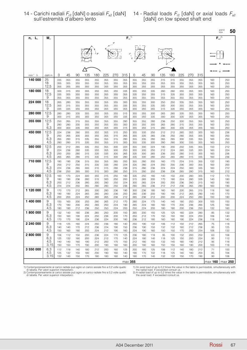
67A04 December 2011
14 - Carichi radiali Fr2 [daN] o assiali Fa2 [daN] sull’estremità d’albero lento
14 - Radial loads Fr2 [daN] or axial loads Fa2 [daN] on low speed shaft end
grand. size 50
1) Contemporaneamente al carico radiale può agire un carico assiale fino a 0,2 volte quello di tabella. Per valori superiori interpellarci.
2) Contemporaneamente al carico assiale può agire un carico radiale fino a 0,2 volte quello di tabella. Per valori superiori interpellarci.
1) An axial load of up to 0,2 times the value in the table is permissible, simultaneously with the radial load. If exceeded consult us.
2) A radial load of up to 0,2 times the value in the table is permissible, simultaneously with the axial load. If exceeded consult us.
n2 · Lh M2 Fr21) Fa2
2)
min-1 · h daN m 0 45 90 135 180 225 270 315 0 45 90 135 180 225 270 315
max 160 max 250max 355
140 000 25 335 355 355 355 355 355 355 355 355 355 355 315 315 355 355 355 160 250 18 355 355 355 355 355 355 355 355 355 355 355 355 355 355 355 355 160 250 12,5 355 355 355 355 355 355 355 355 355 355 355 355 355 355 355 355 160 250
180 000 18 300 315 355 355 355 355 355 335 355 355 335 280 280 355 355 355 160 250 12,5 335 355 355 355 355 355 355 355 335 355 355 315 335 355 355 355 160 250 9 355 355 355 355 355 355 355 355 355 355 355 355 355 355 355 355 160 250
224 000 18 265 280 355 355 355 355 355 300 355 355 300 250 250 335 355 355 160 250 12,5 300 315 355 355 355 355 355 335 355 355 335 300 300 355 355 355 160 250 9 335 335 355 355 355 355 355 355 355 355 355 315 335 355 355 355 160 250
280 000 12,5 280 280 335 355 355 355 355 315 355 355 300 265 265 335 355 355 160 250 9 300 315 355 355 355 355 355 335 355 355 335 300 300 335 355 355 160 250
355 000 12,5 250 265 315 355 355 355 355 280 355 355 280 236 250 300 355 355 160 250 9 280 280 335 355 355 355 355 300 355 355 300 265 280 315 355 355 160 250 6,3 300 300 335 355 355 355 355 315 355 355 315 280 300 335 355 355 160 250
450 000 12,5 224 236 280 355 355 355 315 250 355 335 250 212 212 265 355 355 160 236 9 250 265 300 355 355 355 315 265 355 335 265 236 250 280 355 355 160 250 6,3 265 280 315 335 355 355 315 280 355 335 280 265 265 300 335 355 160 250 4,5 280 280 315 335 355 355 315 300 355 335 300 280 280 300 335 355 160 250
560 000 12,5 200 212 265 335 355 355 300 224 355 300 224 190 200 250 335 355 150 212 9 224 236 280 335 355 355 300 250 355 300 250 212 224 265 335 355 160 224 6,3 250 250 280 315 335 335 300 265 335 300 265 236 250 280 315 355 160 236 4,5 265 265 280 315 335 315 300 280 335 300 280 250 265 280 315 335 160 236
710 000 12,5 180 190 236 315 355 355 265 200 355 280 200 160 170 224 315 355 132 190 9 200 212 250 315 335 335 280 224 335 280 224 200 200 236 300 355 160 200 6,3 224 236 265 300 315 315 280 236 315 280 236 224 224 250 300 335 160 212 4,5 236 250 265 300 315 300 280 250 315 280 250 236 236 265 280 315 160 212
900 000 12,5 160 170 224 300 355 315 250 180 335 250 180 140 150 200 280 355 112 170 9 180 190 236 280 315 300 250 200 315 265 200 170 180 224 280 335 140 180 6,3 200 212 236 280 300 280 250 224 300 265 224 200 200 236 280 315 160 190 4,5 224 224 250 265 280 280 250 236 280 265 236 212 212 236 265 280 160 190
1 120 000 9 170 170 212 265 300 280 236 190 300 236 180 160 160 200 265 315 118 160 6,3 190 190 224 265 280 280 236 200 280 236 200 180 190 212 265 280 140 170 4,5 200 200 224 250 265 265 236 212 265 236 212 200 200 224 250 280 150 180
1 400 000 9 150 160 200 250 280 265 212 170 280 224 170 140 140 180 250 300 100 150 6,3 170 180 200 250 265 250 224 190 265 224 180 160 170 200 236 265 125 160 4,5 180 190 212 236 250 250 224 200 250 224 200 180 180 200 236 250 132 160
1 800 000 9 132 140 180 236 265 250 200 150 265 200 150 125 125 160 224 280 85 132 6,3 150 160 190 224 250 236 200 170 250 212 170 150 150 180 224 250 106 140 4,5 170 170 190 224 236 224 200 180 236 212 180 160 160 190 224 236 118 140
2 240 000 9 118 125 160 224 250 236 180 140 250 190 132 106 112 150 212 265 75 118 6,3 140 140 170 212 236 224 190 150 236 190 150 132 132 160 212 236 95 125 4,5 150 160 180 200 224 212 190 160 224 190 160 150 150 170 200 224 106 132
2 800 000 9 106 112 150 200 236 224 170 125 236 180 118 95 100 132 200 250 63 106 6,3 125 132 160 200 224 212 170 140 224 180 140 118 125 150 200 224 80 112 4,5 140 140 160 190 212 200 170 150 212 180 150 132 140 160 190 212 95 118 3,15 150 150 170 190 200 190 180 160 200 180 160 150 150 160 190 200 100 118
3 550 000 6,3 112 118 140 180 212 200 160 125 200 160 125 106 112 140 180 212 71 100 4,5 125 132 150 180 200 190 160 140 190 170 132 118 125 140 180 200 85 106 3,15 132 140 150 170 180 180 160 140 180 170 140 132 132 150 170 190 90 106
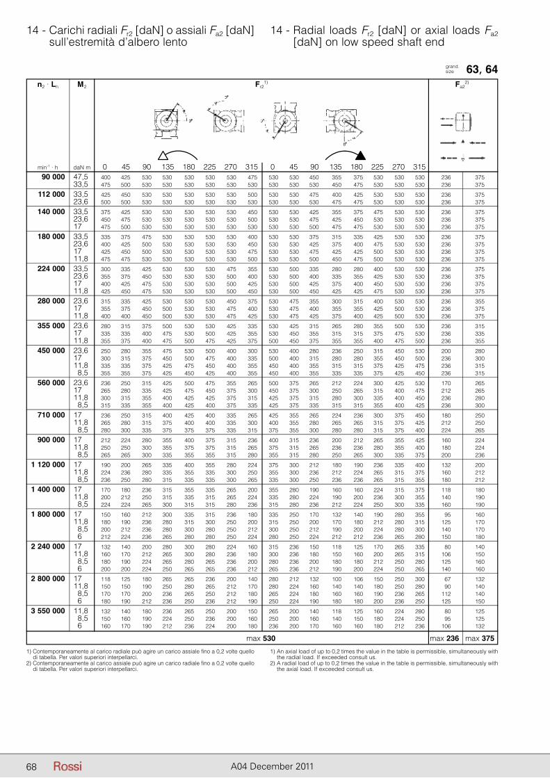
68 A04 December 2011
14 - Carichi radiali Fr2 [daN] o assiali Fa2 [daN] sull’estremità d’albero lento
14 - Radial loads Fr2 [daN] or axial loads Fa2 [daN] on low speed shaft end
grand. size 63, 64
1) Contemporaneamente al carico radiale può agire un carico assiale fino a 0,2 volte quello di tabella. Per valori superiori interpellarci.
2) Contemporaneamente al carico assiale può agire un carico radiale fino a 0,2 volte quello di tabella. Per valori superiori interpellarci.
1) An axial load of up to 0,2 times the value in the table is permissible, simultaneously with the radial load. If exceeded consult us.
2) A radial load of up to 0,2 times the value in the table is permissible, simultaneously with the axial load. If exceeded consult us.
n2 · Lh M2 Fr21) Fa2
2)
min-1 · h daN m 0 45 90 135 180 225 270 315 0 45 90 135 180 225 270 315 90 000 47,5 400 425 530 530 530 530 530 475 530 530 450 355 375 530 530 530 236 375 33,5 475 500 530 530 530 530 530 530 530 530 530 450 475 530 530 530 236 375
112 000 33,5 425 450 530 530 530 530 530 500 530 530 475 400 425 530 530 530 236 375 23,6 500 500 530 530 530 530 530 530 530 530 530 475 475 530 530 530 236 375
140 000 33,5 375 425 530 530 530 530 530 450 530 530 425 355 375 475 530 530 236 375 23,6 450 475 530 530 530 530 530 500 530 530 475 425 450 530 530 530 236 375 17 475 500 530 530 530 530 530 530 530 530 500 475 475 530 530 530 236 375
180 000 33,5 335 375 475 530 530 530 530 400 530 530 375 315 335 425 530 530 236 375 23,6 400 425 500 530 530 530 530 450 530 530 425 375 400 475 530 530 236 375 17 425 450 500 530 530 530 530 475 530 530 475 425 425 500 530 530 236 375 11,8 475 475 530 530 530 530 530 500 530 530 500 450 475 500 530 530 236 375
224 000 33,5 300 335 425 530 530 530 475 355 530 500 335 280 280 400 530 530 236 375 23,6 355 375 450 530 530 530 500 400 530 500 400 335 355 425 530 530 236 375 17 400 425 475 530 530 530 500 425 530 500 425 375 400 450 530 530 236 375 11,8 425 450 475 530 530 530 500 450 530 500 450 425 425 475 530 530 236 375
280 000 23,6 315 335 425 530 530 530 450 375 530 475 355 300 315 400 530 530 236 355 17 355 375 450 500 530 530 475 400 530 475 400 355 355 425 500 530 236 375 11,8 400 400 450 500 530 530 475 425 530 475 425 375 400 425 500 530 236 375
355 000 23,6 280 315 375 500 530 530 425 335 530 425 315 265 280 355 500 530 236 315 17 335 335 400 475 530 500 425 355 530 450 355 315 315 375 475 530 236 335 11,8 355 375 400 475 500 475 425 375 500 450 375 355 355 400 475 500 236 355
450 000 23,6 250 280 355 475 530 500 400 300 530 400 280 236 250 315 450 530 200 280 17 300 315 375 450 500 475 400 335 500 400 315 280 280 355 450 500 236 300 11,8 335 335 375 425 475 450 400 355 450 400 355 315 315 375 425 475 236 315 8,5 355 355 375 425 450 425 400 355 450 400 355 335 335 375 425 450 236 315
560 000 23,6 236 250 315 425 500 475 355 265 500 375 265 212 224 300 425 530 170 265 17 265 280 335 425 475 450 375 300 450 375 300 250 265 315 400 475 212 265 11,8 300 315 355 400 425 425 375 315 425 375 315 280 300 335 400 450 236 280 8,5 315 335 355 400 425 400 375 335 425 375 335 315 315 355 400 425 236 300
710 000 17 236 250 315 400 425 400 335 265 425 355 265 224 236 300 375 450 180 250 11,8 265 280 315 375 400 400 335 300 400 355 280 265 265 315 375 425 212 250 8,5 280 300 335 375 375 375 335 315 375 355 300 280 280 315 375 400 224 265
900 000 17 212 224 280 355 400 375 315 236 400 315 236 200 212 265 355 425 160 224 11,8 250 250 300 355 375 375 315 265 375 315 265 236 236 280 355 400 180 224 8,5 265 265 300 335 355 355 315 280 355 315 280 250 265 300 335 375 200 236
1 120 000 17 190 200 265 335 400 355 280 224 375 300 212 180 190 236 335 400 132 200 11,8 224 236 280 335 355 335 300 250 355 300 236 212 224 265 315 375 160 212 8,5 236 250 280 315 335 335 300 265 335 300 250 236 236 265 315 355 180 212
1 400 000 17 170 180 236 315 355 335 265 200 355 280 190 160 160 224 315 375 118 180 11,8 200 212 250 315 335 315 265 224 335 280 224 190 200 236 300 355 140 190 8,5 224 224 265 300 315 315 280 236 315 280 236 212 224 250 300 335 160 190
1 800 000 17 150 160 212 300 335 315 236 180 335 250 170 132 140 190 280 355 95 160 11,8 180 190 236 280 315 300 250 200 315 250 200 170 180 212 280 315 125 170 8,5 200 212 236 280 300 280 250 212 300 250 212 190 200 224 280 300 140 170 6 212 224 236 265 280 280 250 224 280 250 224 212 212 236 265 280 150 180
2 240 000 17 132 140 200 280 300 280 224 160 315 236 150 118 125 170 265 335 80 140 11,8 160 170 212 265 300 280 236 180 300 236 180 150 160 200 265 315 106 150 8,5 180 190 224 265 280 265 236 200 280 236 200 180 180 212 250 280 125 160 6 200 200 224 250 265 265 236 212 265 236 212 190 200 224 250 265 140 160
2 800 000 17 118 125 180 265 265 236 200 140 280 212 132 100 106 150 250 300 67 132 11,8 150 150 190 250 280 265 212 170 280 224 160 140 140 180 250 280 90 140 8,5 170 170 200 236 265 250 212 180 265 224 180 160 160 190 236 265 112 140 6 180 190 212 236 250 236 212 190 250 224 190 180 180 200 236 250 125 150
3 550 000 11,8 132 140 180 236 265 250 200 150 265 200 140 118 125 160 224 280 80 125 8,5 150 160 190 224 250 236 200 160 250 200 160 140 150 180 224 250 95 125 6 160 170 190 212 236 224 200 180 236 200 170 160 160 180 212 236 106 132
max 236 max 375max 530
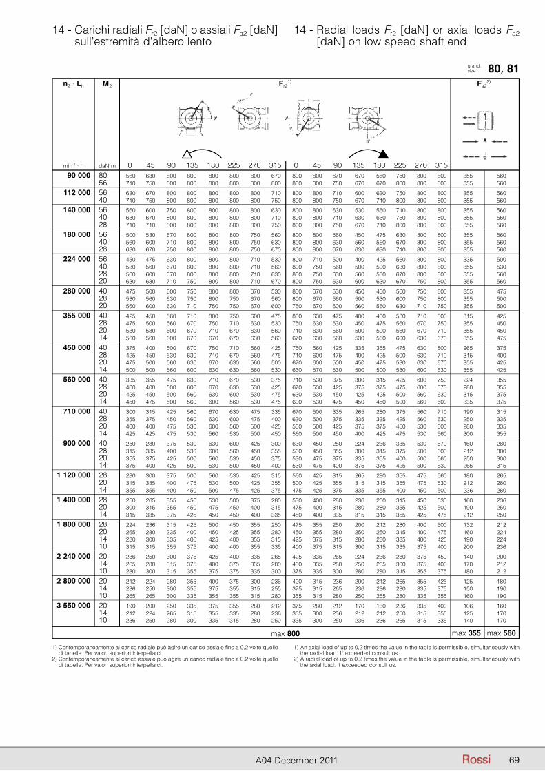
69A04 December 2011
14 - Carichi radiali Fr2 [daN] o assiali Fa2 [daN] sull’estremità d’albero lento
14 - Radial loads Fr2 [daN] or axial loads Fa2 [daN] on low speed shaft end
grand. size 80, 81
1) Contemporaneamente al carico radiale può agire un carico assiale fino a 0,2 volte quello di tabella. Per valori superiori interpellarci.
2) Contemporaneamente al carico assiale può agire un carico radiale fino a 0,2 volte quello di tabella. Per valori superiori interpellarci.
1) An axial load of up to 0,2 times the value in the table is permissible, simultaneously with the radial load. If exceeded consult us.
2) A radial load of up to 0,2 times the value in the table is permissible, simultaneously with the axial load. If exceeded consult us.
n2 · Lh M2 Fr21) Fa2
2)
min-1 · h daN m 0 45 90 135 180 225 270 315 0 45 90 135 180 225 270 315 90 000 80 560 630 800 800 800 800 800 670 800 800 670 670 560 750 800 800 355 560 56 710 750 800 800 800 800 800 800 800 800 750 670 670 800 800 800 355 560
112 000 56 630 670 800 800 800 800 800 710 800 800 710 600 630 750 800 800 355 560 40 710 750 800 800 800 800 800 750 800 800 750 670 710 800 800 800 355 560
140 000 56 560 600 750 800 800 800 800 630 800 800 630 530 560 710 800 800 355 560 40 630 670 800 800 800 800 800 710 800 800 710 630 630 750 800 800 355 560 28 710 710 800 800 800 800 800 750 800 800 750 670 710 800 800 800 355 560
180 000 56 500 530 670 800 800 800 750 560 800 800 560 450 475 630 800 800 355 560 40 560 600 710 800 800 800 750 630 800 800 630 560 560 670 800 800 355 560 28 630 670 750 800 800 800 750 670 800 800 670 630 630 710 800 800 355 560
224 000 56 450 475 630 800 800 800 710 530 800 710 500 400 425 560 800 800 335 500 40 530 560 670 800 800 800 710 560 800 750 560 500 500 630 800 800 355 530 28 560 600 670 800 800 800 710 630 800 750 630 560 560 670 800 800 355 560 20 630 630 710 750 800 800 710 670 800 750 630 600 630 670 750 800 355 560
280 000 40 475 500 600 750 800 800 670 530 800 670 530 450 450 560 750 800 355 475 28 530 560 630 750 800 750 670 560 800 670 560 500 530 600 750 800 355 500 20 560 600 630 710 750 750 670 600 750 670 600 560 560 630 710 750 355 500
355 000 40 425 450 560 710 800 750 600 475 800 630 475 400 400 530 710 800 315 425 28 475 500 560 670 750 710 630 530 750 630 530 450 475 560 670 750 355 450 20 530 530 600 670 710 670 630 560 710 630 560 500 500 560 670 710 355 450 14 560 560 600 670 670 670 630 560 670 630 560 530 560 600 630 670 355 475
450 000 40 375 400 500 670 750 710 560 425 750 560 425 335 355 475 630 800 265 375 28 425 450 530 630 710 670 560 475 710 600 475 400 425 500 630 710 315 400 20 475 500 560 630 670 630 560 500 670 600 500 450 475 530 630 670 355 425 14 500 500 560 600 630 630 560 530 630 570 530 500 500 530 600 630 355 425
560 000 40 335 355 475 630 710 670 530 375 710 530 375 300 315 425 600 750 224 355 28 400 400 500 600 670 630 530 425 670 530 425 375 375 475 600 670 280 355 20 425 450 500 560 630 600 530 475 630 530 450 425 425 500 560 630 315 375 14 450 475 500 560 600 560 530 475 600 530 475 450 450 500 560 600 335 375
710 000 40 300 315 425 560 670 630 475 335 670 500 335 265 280 375 560 710 190 315 28 355 375 450 560 630 600 475 400 630 500 375 335 335 425 560 630 250 335 20 400 400 475 530 600 560 500 425 560 500 425 375 375 450 530 600 280 335 14 425 425 475 530 560 530 500 450 560 500 450 400 425 475 530 560 300 355
900 000 40 250 280 375 530 630 600 425 300 630 450 280 224 236 335 530 670 160 280 28 315 335 400 530 600 560 450 355 560 450 355 300 315 375 500 600 212 300 20 355 375 425 500 560 530 450 375 530 475 375 335 355 400 500 560 250 300 14 375 400 425 500 530 500 450 400 530 475 400 375 375 425 500 530 265 315
1 120 000 28 280 300 375 500 560 530 425 315 560 425 315 265 280 355 475 560 180 265 20 315 335 400 475 530 500 425 355 500 425 355 315 315 355 475 530 212 280 14 355 355 400 450 500 475 425 375 475 425 375 335 355 400 450 500 236 280
1 400 000 28 250 265 355 450 530 500 375 280 530 400 280 236 250 315 450 530 160 236 20 300 315 355 450 475 450 400 315 475 400 315 280 280 355 425 500 190 250 14 315 335 375 425 450 450 400 335 450 400 335 315 315 355 425 475 212 250
1 800 000 28 224 236 315 425 500 450 355 250 475 355 250 200 212 280 400 500 132 212 20 265 280 335 400 450 425 355 280 450 355 280 250 250 315 400 475 160 224 14 280 300 335 400 425 400 355 315 425 375 315 280 280 335 400 425 190 224 10 315 315 355 375 400 400 355 335 400 375 315 300 315 335 375 400 200 236
2 240 000 20 236 250 300 375 425 400 335 265 425 335 265 224 236 280 375 450 140 200 14 265 280 315 375 400 375 335 280 400 335 280 250 265 300 375 400 170 212 10 280 300 315 355 375 375 335 300 375 335 300 280 280 315 355 375 180 212
2 800 000 20 212 224 280 355 400 375 300 236 400 315 236 200 212 265 355 425 125 180 14 236 250 300 355 375 355 315 255 375 315 265 236 236 280 335 375 150 190 10 265 265 300 335 355 355 315 280 355 315 280 250 265 280 335 355 160 190
3 550 000 20 190 200 250 335 375 355 280 212 375 280 212 170 180 236 335 400 106 160 14 212 224 265 315 355 335 280 236 355 300 236 212 212 250 315 355 125 170 10 236 250 280 300 335 315 280 250 335 300 250 236 236 265 315 335 140 170
max 355 max 560max 800
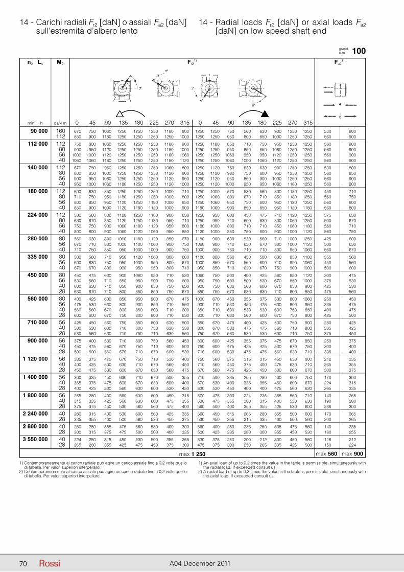
70 A04 December 2011
14 - Carichi radiali Fr2 [daN] o assiali Fa2 [daN] sull’estremità d’albero lento
14 - Radial loads Fr2 [daN] or axial loads Fa2 [daN] on low speed shaft end
grand. size 100
1) Contemporaneamente al carico radiale può agire un carico assiale fino a 0,2 volte quello di tabella. Per valori superiori interpellarci.
2) Contemporaneamente al carico assiale può agire un carico radiale fino a 0,2 volte quello di tabella. Per valori superiori interpellarci.
1) An axial load of up to 0,2 times the value in the table is permissible, simultaneously with the radial load. If exceeded consult us.
2) A radial load of up to 0,2 times the value in the table is permissible, simultaneously with the axial load. If exceeded consult us.
n2 · Lh M2 Fr21) Fa2
2)
min-1 · h daN m 0 45 90 135 180 225 270 315 0 45 90 135 180 225 270 315 90 000 160 670 750 1060 1250 1250 1250 1180 800 1250 1250 750 560 630 900 1250 1250 530 900 112 850 900 1180 1250 1250 1250 1250 1000 1250 1250 950 800 850 1000 1250 1250 560 900
112 000 112 750 800 1060 1250 1250 1250 1180 900 1250 1180 850 710 750 950 1250 1250 560 900 80 900 950 1120 1250 1250 1250 1180 1000 1250 1250 950 850 850 1060 1250 1250 560 900 56 1000 1000 1120 1250 1250 1250 1180 1060 1250 1250 1060 950 950 1120 1250 1250 560 900 40 1060 1060 1180 1250 1250 1250 1180 1120 1250 1250 1060 1000 1060 1120 1250 1250 560 900
140 000 112 670 750 950 1250 1250 1250 1060 800 1250 1120 750 630 630 900 1250 1250 530 800 80 800 850 1000 1250 1250 1250 1120 900 1250 1120 900 750 800 950 1250 1250 560 850 56 900 950 1060 1250 1250 1250 1120 950 1250 1120 950 850 900 1000 1250 1250 560 900 40 950 1000 1060 1180 1250 1250 1120 1000 1250 1120 1000 950 950 1060 1180 1250 560 900
180 000 112 600 630 850 1250 1250 1250 1000 710 1250 1000 670 530 560 800 1180 1250 450 710 80 710 750 950 1180 1250 1250 1000 800 1250 1060 800 670 710 850 1180 1250 560 750 56 800 850 950 1120 1250 1180 1000 850 1250 1060 850 750 800 950 1120 1250 560 800 40 850 900 1000 1120 1180 1120 1000 900 1180 1060 900 850 850 950 1120 1180 560 800
224 000 112 530 560 800 1120 1250 1180 900 630 1250 950 600 450 475 710 1120 1250 375 630 80 630 670 850 1120 1250 1180 950 710 1250 950 710 600 630 800 1060 1250 500 670 56 750 750 900 1060 1180 1120 950 800 1180 1000 800 710 710 850 1060 1180 560 710 40 800 800 900 1060 1120 1060 950 850 1120 1000 850 750 800 900 1000 1120 560 750
280 000 80 560 630 800 1060 1180 1120 850 670 1180 900 630 530 560 710 1000 1250 425 600 56 670 710 800 1000 1120 1060 900 750 1060 900 710 630 670 800 1000 1120 500 630 40 710 750 850 950 1000 1000 900 750 1000 900 750 710 710 800 950 1060 560 670
335 000 80 500 560 710 950 1120 1060 800 600 1120 800 560 450 500 630 950 1180 355 560 56 600 630 750 950 1000 950 800 670 1000 850 670 560 600 710 900 1060 450 560 40 670 670 800 900 950 950 800 710 950 850 710 630 670 750 900 1000 500 600
450 000 80 450 475 630 900 1060 950 710 530 1060 750 500 400 425 560 850 1120 300 475 56 530 560 710 850 950 900 750 600 950 750 600 500 530 670 850 1000 375 530 40 600 630 710 850 900 850 750 630 900 750 630 560 600 670 850 900 425 530 28 630 670 710 800 850 850 750 670 850 750 670 630 630 710 800 850 475 560
560 000 80 400 425 600 850 950 900 670 475 1000 670 450 355 375 530 800 1060 250 450 56 475 530 630 800 900 850 710 560 900 710 530 450 475 600 800 950 335 475 40 560 560 670 800 850 800 710 600 850 710 600 530 530 630 750 850 400 475 28 600 600 670 750 800 800 710 630 800 710 630 560 600 670 750 800 425 500
710 000 56 425 450 560 750 850 800 630 500 850 670 475 400 425 530 750 900 280 425 40 500 530 600 710 800 750 630 530 800 670 530 475 475 560 710 800 335 425 28 530 560 630 710 750 710 630 560 750 670 560 530 530 600 710 750 375 450
900 000 56 375 400 530 710 800 750 560 450 800 600 425 355 375 475 670 850 250 375 40 450 475 560 670 750 710 600 500 750 600 475 425 425 530 670 750 300 400 28 500 500 560 670 710 670 600 530 710 600 530 475 475 560 630 710 335 400
1 120 000 56 335 375 475 670 750 710 530 400 750 560 375 315 315 450 630 800 212 335 40 400 425 500 630 710 670 560 450 710 560 450 375 400 475 630 710 265 355 28 450 475 530 600 670 630 560 475 670 560 475 425 450 500 600 670 300 375
1 400 000 56 300 335 450 630 710 670 500 355 710 500 335 265 280 400 600 750 170 300 40 355 375 475 600 670 630 500 400 670 530 400 335 355 450 600 670 224 315 28 400 425 500 560 630 600 530 450 630 530 450 400 400 475 560 630 265 335
1 800 000 56 265 280 400 560 630 600 450 315 670 475 300 224 236 355 560 710 140 265 40 315 335 425 560 630 600 475 355 630 475 355 300 315 400 530 630 190 280 28 375 375 450 530 560 560 475 400 560 500 400 355 355 425 530 600 236 300
2 240 000 40 280 315 400 530 600 560 425 335 560 450 315 265 280 355 500 600 170 265 28 335 355 400 500 560 530 450 375 530 450 355 315 335 400 500 560 200 265
2 800 000 40 250 280 355 475 560 530 400 300 560 400 280 236 250 335 475 560 140 235 28 300 315 375 475 500 500 400 335 500 425 335 280 300 355 450 530 180 255
3 550 000 40 224 250 315 450 530 500 355 265 530 375 250 200 212 300 450 560 118 212 28 265 280 355 425 475 450 375 300 475 375 300 250 265 335 425 500 150 224
max 560 max 900max 1 250
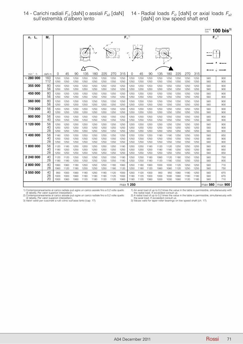
71A04 December 2011
14 - Carichi radiali Fr2 [daN] o assiali Fa2 [daN] sull’estremità d’albero lento
14 - Radial loads Fr2 [daN] or axial loads Fa2 [daN] on low speed shaft end
grand. size 100 bis3)
1) Contemporaneamente al carico radiale può agire un carico assiale fino a 0,2 volte quello di tabella. Per valori superiori interpellarci.
2) Contemporaneamente al carico assiale può agire un carico radiale fino a 0,2 volte quello di tabella. Per valori superiori interpellarci.
3) Valori validi per cuscinetti a rulli conici sull’asse lento (cap. 17).
1) An axial load of up to 0,2 times the value in the table is permissible, simultaneously with the radial load. If exceeded consult us.
2) A radial load of up to 0,2 times the value in the table is permissible, simultaneously with the axial load. If exceeded consult us.
3) Values valid for taper roller bearings on low speed shaft (ch. 17).
n2 · Lh M2 Fr21) Fa2
2)
min-1 · h daN m 0 45 90 135 180 225 270 315 0 45 90 135 180 225 270 315 � 280 000 160 1250 1250 1250 1250 1250 1250 1250 1250 1250 1250 1250 1250 1250 1250 1250 1250 560 900 112 1250 1250 1250 1250 1250 1250 1250 1250 1250 1250 1250 1250 1250 1250 1250 1250 560 900
355 000 80 1250 1250 1250 1250 1250 1250 1250 1250 1250 1250 1250 1250 1250 1250 1250 1250 560 900 56 1250 1250 1250 1250 1250 1250 1250 1250 1250 1250 1250 1250 1250 1250 1250 1250 560 900
450 000 80 1250 1250 1250 1250 1250 1250 1250 1250 1250 1250 1250 1250 1250 1250 1250 1250 560 900 56 1250 1250 1250 1250 1250 1250 1250 1250 1250 1250 1250 1250 1250 1250 1250 1250 560 900
560 000 80 1250 1250 1250 1250 1250 1250 1250 1250 1250 1250 1250 1250 1250 1250 1250 1250 560 900 56 1250 1250 1250 1250 1250 1250 1250 1250 1250 1250 1250 1250 1250 1250 1250 1250 560 900
710 000 56 1250 1250 1250 1250 1250 1250 1250 1250 1250 1250 1250 1250 1250 1250 1250 1250 560 900 40 1250 1250 1250 1250 1250 1250 1250 1250 1250 1250 1250 1250 1250 1250 1250 1250 560 900
900 000 56 1250 1250 1250 1250 1250 1250 1250 1250 1250 1250 1250 1250 1250 1250 1250 1250 560 900 40 1250 1250 1250 1250 1250 1250 1250 1250 1250 1250 1250 1250 1250 1250 1250 1250 560 900
1 120 000 56 1250 1250 1250 1250 1250 1250 1250 1250 1250 1250 1250 1250 1250 1250 1250 1250 560 900 40 1250 1250 1250 1250 1250 1250 1250 1250 1250 1250 1250 1250 1250 1250 1250 1250 560 900 28 1250 1250 1250 1250 1250 1250 1250 1250 1250 1250 1250 1250 1250 1250 1250 1250 560 900
1 400 000 56 1180 1250 1250 1250 1250 1250 1250 1250 1250 1250 1250 1180 1180 1250 1250 1250 560 850 40 1250 1250 1250 1250 1250 1250 1250 1250 1250 1250 1250 1250 1250 1250 1250 1250 560 900 28 1250 1250 1250 1250 1250 1250 1250 1250 1250 1250 1250 1250 1250 1250 1250 1250 560 900
1 800 000 56 1120 1180 1250 1250 1250 1250 1250 1180 1250 1250 1180 1120 1120 1250 1250 1250 560 800 40 1180 1250 1250 1250 1250 1250 1250 1250 1250 1250 1250 1180 1180 1250 1250 1250 560 850 28 1250 1250 1250 1250 1250 1250 1250 1250 1250 1250 1250 1250 1250 1250 1250 1250 560 850
2 240 000 40 1120 1120 1250 1250 1250 1250 1250 1180 1250 1250 1180 1060 1120 1180 1250 1250 560 750 28 1180 1180 1250 1250 1250 1250 1250 1180 1250 1250 1180 1120 1180 1250 1250 1250 560 800
2 800 000 40 1060 1060 1180 1250 1250 1250 1180 1060 1250 1180 1060 1000 1000 1120 1250 1250 560 710 28 1060 1120 1180 1250 1250 1250 1180 1120 1250 1180 1120 1060 1060 1120 1250 1250 560 750
3 550 000 40 950 1000 1060 1180 1250 1180 1120 1000 1250 1120 1000 950 950 1060 1180 1250 560 670 28 1000 1000 1060 1180 1180 1180 1120 1000 1180 1120 1000 1000 1000 1060 1180 1180 560 670 20 1000 1060 1060 1120 1180 1120 1120 1060 1180 1120 1060 1000 1000 1060 1120 1180 560 710
max 560 max 900max 1 250
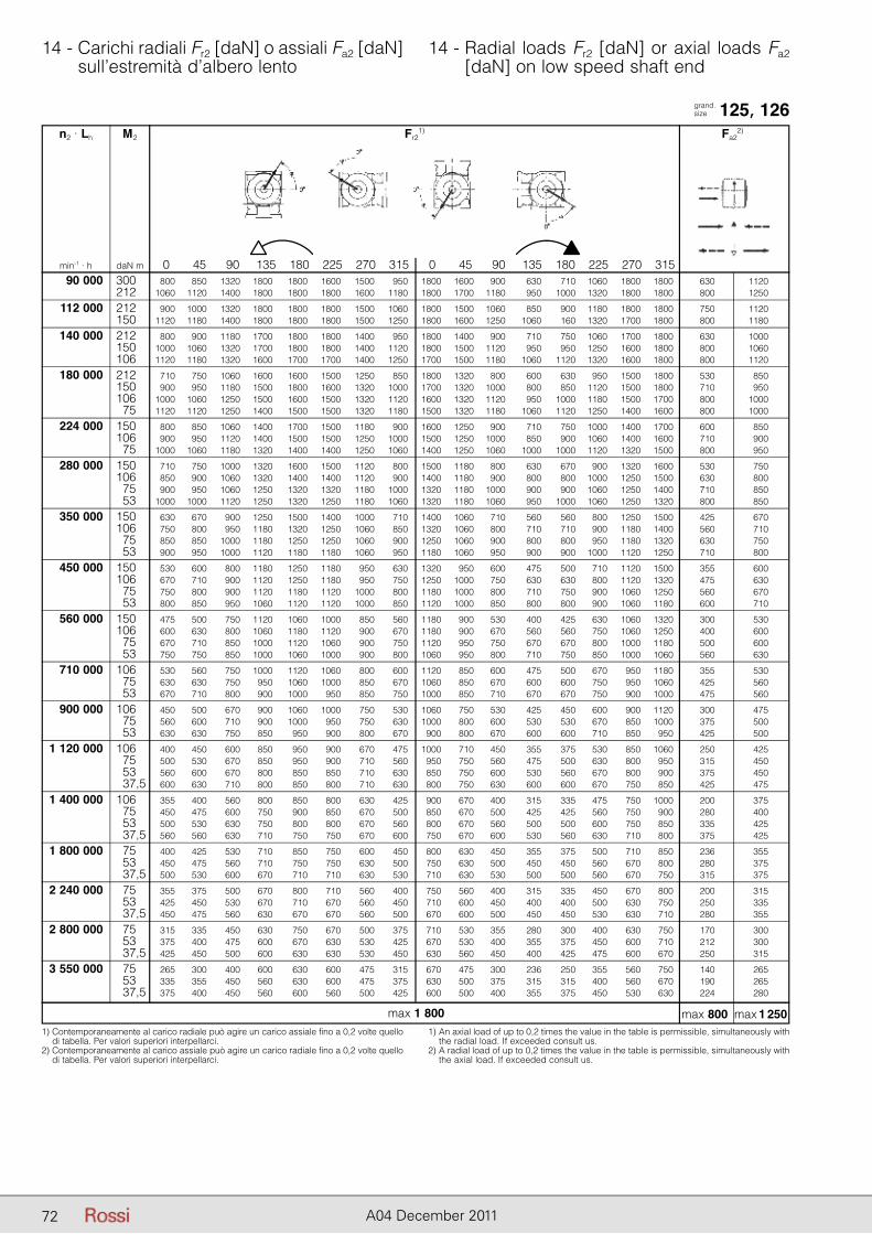
72 A04 December 2011
14 - Carichi radiali Fr2 [daN] o assiali Fa2 [daN] sull’estremità d’albero lento
14 - Radial loads Fr2 [daN] or axial loads Fa2 [daN] on low speed shaft end
grand. size 125, 126
1) Contemporaneamente al carico radiale può agire un carico assiale fino a 0,2 volte quello di tabella. Per valori superiori interpellarci.
2) Contemporaneamente al carico assiale può agire un carico radiale fino a 0,2 volte quello di tabella. Per valori superiori interpellarci.
1) An axial load of up to 0,2 times the value in the table is permissible, simultaneously with the radial load. If exceeded consult us.
2) A radial load of up to 0,2 times the value in the table is permissible, simultaneously with the axial load. If exceeded consult us.
n2 · Lh M2 Fr21) Fa2
2)
min-1 · h daN m 0 45 90 135 180 225 270 315 0 45 90 135 180 225 270 315 90 000 300 800 850 1320 1800 1800 1600 1500 950 1800 1600 900 630 710 1060 1800 1800 630 1120 212 1060 1120 1400 1800 1800 1800 1600 1180 1800 1700 1180 950 1000 1320 1800 1800 800 1250
112 000 212 900 1000 1320 1800 1800 1800 1500 1060 1800 1500 1060 850 900 1180 1800 1800 750 1120 150 1120 1180 1400 1800 1800 1800 1500 1250 1800 1600 1250 1060 160 1320 1700 1800 800 1180
140 000 212 800 900 1180 1700 1800 1800 1400 950 1800 1400 900 710 750 1060 1700 1800 630 1000 150 1000 1060 1320 1700 1800 1800 1400 1120 1800 1500 1120 950 950 1250 1600 1800 800 1060 106 1120 1180 1320 1600 1700 1700 1400 1250 1700 1500 1180 1060 1120 1320 1600 1800 800 1120
180 000 212 710 750 1060 1600 1600 1500 1250 850 1800 1320 800 600 630 950 1500 1800 530 850 150 900 950 1180 1500 1800 1600 1320 1000 1700 1320 1000 800 850 1120 1500 1800 710 950 106 1000 1060 1250 1500 1600 1500 1320 1120 1600 1320 1120 950 1000 1180 1500 1700 800 1000 75 1120 1120 1250 1400 1500 1500 1320 1180 1500 1320 1180 1060 1120 1250 1400 1600 800 1000
224 000 150 800 850 1060 1400 1700 1500 1180 900 1600 1250 900 710 750 1000 1400 1700 600 850 106 900 950 1120 1400 1500 1500 1250 1000 1500 1250 1000 850 900 1060 1400 1600 710 900 75 1000 1060 1180 1320 1400 1400 1250 1060 1400 1250 1060 1000 1000 1120 1320 1500 800 950
280 000 150 710 750 1000 1320 1600 1500 1120 800 1500 1180 800 630 670 900 1320 1600 530 750 106 850 900 1060 1320 1400 1400 1120 900 1400 1180 900 800 800 1000 1250 1500 630 800 75 900 950 1060 1250 1320 1320 1180 1000 1320 1180 1000 900 900 1060 1250 1400 710 850 53 1000 1000 1120 1250 1320 1250 1180 1060 1320 1180 1060 950 1000 1060 1250 1320 800 850
350 000 150 630 670 900 1250 1500 1400 1000 710 1400 1060 710 560 560 800 1250 1500 425 670 106 750 800 950 1180 1320 1250 1060 850 1320 1060 800 710 710 900 1180 1400 560 710 75 850 850 1000 1180 1250 1250 1060 900 1250 1060 900 800 800 950 1180 1320 630 750 53 900 950 1000 1120 1180 1180 1060 950 1180 1060 950 900 900 1000 1120 1250 710 800
450 000 150 530 600 800 1180 1250 1180 950 630 1320 950 600 475 500 710 1120 1500 355 600 106 670 710 900 1120 1250 1180 950 750 1250 1000 750 630 630 800 1120 1320 475 630 75 750 800 900 1120 1180 1120 1000 800 1180 1000 800 710 750 900 1060 1250 560 670 53 800 850 950 1060 1120 1120 1000 850 1120 1000 850 800 800 900 1060 1180 600 710
560 000 150 475 500 750 1120 1060 1000 850 560 1180 900 530 400 425 630 1060 1320 300 530 106 600 630 800 1060 1180 1120 900 670 1180 900 670 560 560 750 1060 1250 400 600 75 670 710 850 1000 1120 1060 900 750 1120 950 750 670 670 800 1000 1180 500 600 53 750 750 850 1000 1060 1000 900 800 1060 950 800 710 750 850 1000 1060 560 630
710 000 106 530 560 750 1000 1120 1060 800 600 1120 850 600 475 500 670 950 1180 355 530 75 630 630 750 950 1060 1000 850 670 1060 850 670 600 600 750 950 1060 425 560 53 670 710 800 900 1000 950 850 750 1000 850 710 670 670 750 900 1000 475 560
900 000 106 450 500 670 900 1060 1000 750 530 1060 750 530 425 450 600 900 1120 300 475 75 560 600 710 900 1000 950 750 630 1000 800 600 530 530 670 850 1000 375 500 53 630 630 750 850 950 900 800 670 900 800 670 600 600 710 850 950 425 500
1 120 000 106 400 450 600 850 950 900 670 475 1000 710 450 355 375 530 850 1060 250 425 75 500 530 670 850 950 900 710 560 950 750 560 475 500 630 800 950 315 450 53 560 600 670 800 850 850 710 630 850 750 600 530 560 670 800 900 375 450 37,5 600 630 710 800 850 800 710 630 800 750 630 600 600 670 750 850 425 475
1 400 000 106 355 400 560 800 850 800 630 425 900 670 400 315 335 475 750 1000 200 375 75 450 475 600 750 900 850 670 500 850 670 500 425 425 560 750 900 280 400 53 500 530 630 750 800 800 670 560 800 670 560 500 500 600 750 850 335 425 37,5 560 560 630 710 750 750 670 600 750 670 600 530 560 630 710 800 375 425
1 800 000 75 400 425 530 710 850 750 600 450 800 630 450 355 375 500 710 850 236 355 53 450 475 560 710 750 750 630 500 750 630 500 450 450 560 670 800 280 375 37,5 500 530 600 670 710 710 630 530 710 630 530 500 500 560 670 750 315 375
2 240 000 75 355 375 500 670 800 710 560 400 750 560 400 315 335 450 670 800 200 315 53 425 450 530 670 710 670 560 450 710 600 450 400 400 500 630 750 250 335 37,5 450 475 560 630 670 670 560 500 670 600 500 450 450 530 630 710 280 355
2 800 000 75 315 335 450 630 750 670 500 375 710 530 355 280 300 400 630 750 170 300 53 375 400 475 600 670 630 530 425 670 530 400 355 375 450 600 710 212 300 37,5 425 450 500 600 630 630 530 450 630 560 450 400 425 475 600 670 250 315
3 550 000 75 265 300 400 600 630 600 475 315 670 475 300 236 250 355 560 750 140 265 53 335 355 450 560 630 600 475 375 630 500 375 315 315 400 560 670 190 265 37,5 375 400 450 560 600 560 500 425 600 500 400 355 375 450 530 630 224 280
max 800 max 1 250max 1 800
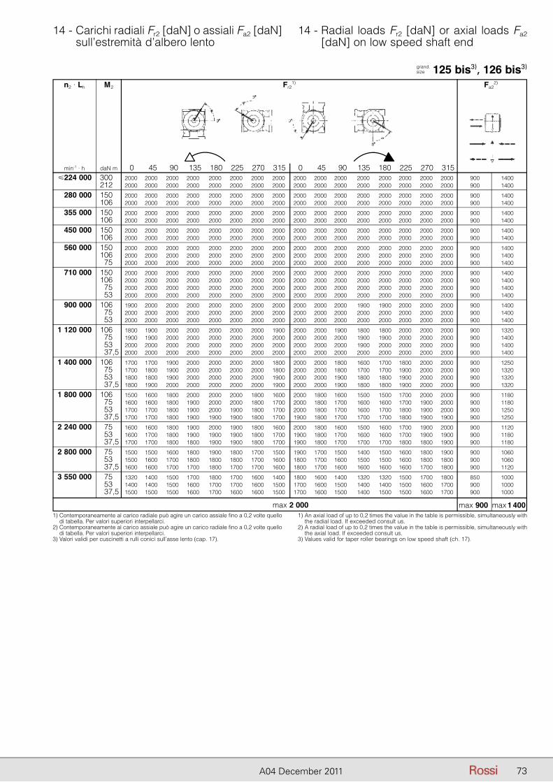
73A04 December 2011
14 - Carichi radiali Fr2 [daN] o assiali Fa2 [daN] sull’estremità d’albero lento
14 - Radial loads Fr2 [daN] or axial loads Fa2 [daN] on low speed shaft end
grand. size 125 bis3), 126 bis3)
1) Contemporaneamente al carico radiale può agire un carico assiale fino a 0,2 volte quello di tabella. Per valori superiori interpellarci.
2) Contemporaneamente al carico assiale può agire un carico radiale fino a 0,2 volte quello di tabella. Per valori superiori interpellarci.
3) Valori validi per cuscinetti a rulli conici sull’asse lento (cap. 17).
1) An axial load of up to 0,2 times the value in the table is permissible, simultaneously with the radial load. If exceeded consult us.
2) A radial load of up to 0,2 times the value in the table is permissible, simultaneously with the axial load. If exceeded consult us.
3) Values valid for taper roller bearings on low speed shaft (ch. 17).
n2 · Lh M2 Fr21) Fa2
2)
min-1 · h daN m 0 45 90 135 180 225 270 315 0 45 90 135 180 225 270 315 �224 000 300 2000 2000 2000 2000 2000 2000 2000 2000 2000 2000 2000 2000 2000 2000 2000 2000 900 1400 212 2000 2000 2000 2000 2000 2000 2000 2000 2000 2000 2000 2000 2000 2000 2000 2000 900 1400
280 000 150 2000 2000 2000 2000 2000 2000 2000 2000 2000 2000 2000 2000 2000 2000 2000 2000 900 1400 106 2000 2000 2000 2000 2000 2000 2000 2000 2000 2000 2000 2000 2000 2000 2000 2000 900 1400
355 000 150 2000 2000 2000 2000 2000 2000 2000 2000 2000 2000 2000 2000 2000 2000 2000 2000 900 1400 106 2000 2000 2000 2000 2000 2000 2000 2000 2000 2000 2000 2000 2000 2000 2000 2000 900 1400
450 000 150 2000 2000 2000 2000 2000 2000 2000 2000 2000 2000 2000 2000 2000 2000 2000 2000 900 1400 106 2000 2000 2000 2000 2000 2000 2000 2000 2000 2000 2000 2000 2000 2000 2000 2000 900 1400
560 000 150 2000 2000 2000 2000 2000 2000 2000 2000 2000 2000 2000 2000 2000 2000 2000 2000 900 1400 106 2000 2000 2000 2000 2000 2000 2000 2000 2000 2000 2000 2000 2000 2000 2000 2000 900 1400 75 2000 2000 2000 2000 2000 2000 2000 2000 2000 2000 2000 2000 2000 2000 2000 2000 900 1400
710 000 150 2000 2000 2000 2000 2000 2000 2000 2000 2000 2000 2000 2000 2000 2000 2000 2000 900 1400 106 2000 2000 2000 2000 2000 2000 2000 2000 2000 2000 2000 2000 2000 2000 2000 2000 900 1400 75 2000 2000 2000 2000 2000 2000 2000 2000 2000 2000 2000 2000 2000 2000 2000 2000 900 1400 53 2000 2000 2000 2000 2000 2000 2000 2000 2000 2000 2000 2000 2000 2000 2000 2000 900 1400
900 000 106 1900 2000 2000 2000 2000 2000 2000 2000 2000 2000 2000 1900 1900 2000 2000 2000 900 1400 75 2000 2000 2000 2000 2000 2000 2000 2000 2000 2000 2000 2000 2000 2000 2000 2000 900 1400 53 2000 2000 2000 2000 2000 2000 2000 2000 2000 2000 2000 2000 2000 2000 2000 2000 900 1400
1 120 000 106 1800 1900 2000 2000 2000 2000 2000 1900 2000 2000 1900 1800 1800 2000 2000 2000 900 1320 75 1900 1900 2000 2000 2000 2000 2000 2000 2000 2000 2000 1900 1900 2000 2000 2000 900 1400 53 2000 2000 2000 2000 2000 2000 2000 2000 2000 2000 2000 1900 2000 2000 2000 2000 900 1400 37,5 2000 2000 2000 2000 2000 2000 2000 2000 2000 2000 2000 2000 2000 2000 2000 2000 900 1400
1 400 000 106 1700 1700 1900 2000 2000 2000 2000 1800 2000 2000 1800 1600 1700 1800 2000 2000 900 1250 75 1700 1800 1900 2000 2000 2000 2000 1800 2000 2000 1800 1700 1700 1900 2000 2000 900 1320 53 1800 1800 1900 2000 2000 2000 2000 1900 2000 2000 1900 1800 1800 1900 2000 2000 900 1320 37,5 1800 1900 2000 2000 2000 2000 2000 1900 2000 2000 1900 1800 1800 1900 2000 2000 900 1320
1 800 000 106 1500 1600 1800 2000 2000 2000 1800 1600 2000 1800 1600 1500 1500 1700 2000 2000 900 1180 75 1600 1600 1800 1900 2000 2000 1800 1700 2000 1800 1700 1600 1600 1700 1900 2000 900 1180 53 1700 1700 1800 1900 2000 1900 1800 1700 2000 1800 1700 1600 1700 1800 1900 2000 900 1250 37,5 1700 1700 1800 1900 1900 1900 1800 1700 1900 1800 1700 1700 1700 1800 1900 1900 900 1250
2 240 000 75 1600 1600 1800 1900 2000 1900 1800 1600 2000 1800 1600 1500 1600 1700 1900 2000 900 1120 53 1600 1700 1800 1900 1900 1900 1800 1700 1900 1800 1700 1600 1600 1700 1900 1900 900 1180 37,5 1700 1700 1800 1800 1900 1900 1800 1700 1900 1800 1700 1700 1700 1800 1800 1900 900 1180
2 800 000 75 1500 1500 1600 1800 1900 1800 1700 1500 1900 1700 1500 1400 1500 1600 1800 1900 900 1060 53 1500 1600 1700 1800 1800 1800 1700 1600 1800 1700 1600 1500 1500 1600 1800 1800 900 1060 37,5 1600 1600 1700 1700 1800 1700 1700 1600 1800 1700 1600 1600 1600 1600 1700 1800 900 1120
3 550 000 75 1320 1400 1500 1700 1800 1700 1600 1400 1800 1600 1400 1320 1320 1500 1700 1800 850 1000 53 1400 1400 1500 1600 1700 1700 1600 1500 1700 1600 1500 1400 1400 1500 1600 1700 900 1000 37,5 1500 1500 1500 1600 1700 1600 1600 1500 1700 1600 1500 1400 1500 1500 1600 1700 900 1000
max 900 max 1 400max 2 000
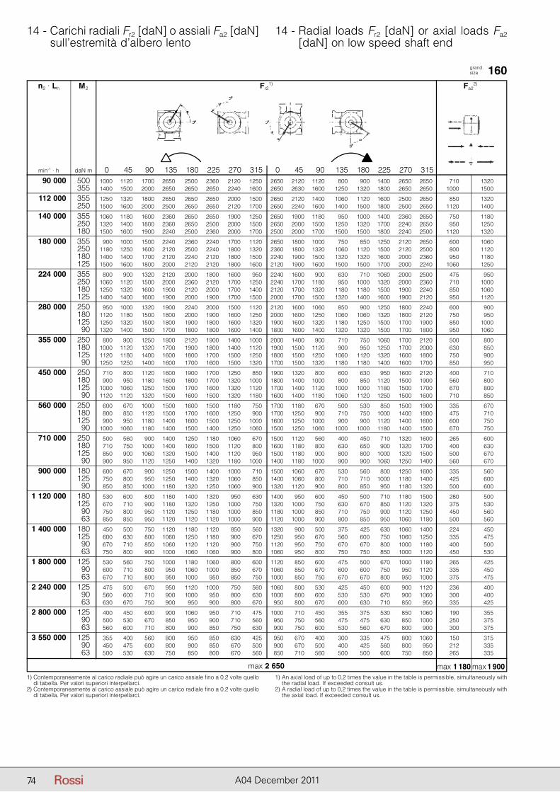
74 A04 December 2011
14 - Carichi radiali Fr2 [daN] o assiali Fa2 [daN] sull’estremità d’albero lento
14 - Radial loads Fr2 [daN] or axial loads Fa2 [daN] on low speed shaft end
grand. size 160
1) Contemporaneamente al carico radiale può agire un carico assiale fino a 0,2 volte quello di tabella. Per valori superiori interpellarci.
2) Contemporaneamente al carico assiale può agire un carico radiale fino a 0,2 volte quello di tabella. Per valori superiori interpellarci.
1) An axial load of up to 0,2 times the value in the table is permissible, simultaneously with the radial load. If exceeded consult us.
2) A radial load of up to 0,2 times the value in the table is permissible, simultaneously with the axial load. If exceeded consult us.
n2 · Lh M2 Fr21) Fa2
2)
min-1 · h daN m 0 45 90 135 180 225 270 315 0 45 90 135 180 225 270 315 90 000 500 1000 1120 1700 2650 2500 2360 2120 1250 2650 2120 1120 800 900 1400 2650 2650 710 1320 355 1400 1500 2000 2650 2650 2650 2240 1600 2650 2630 1600 1250 1320 1800 2650 2650 1000 1500
112 000 355 1250 1320 1800 2650 2650 2650 2000 1500 2650 2120 1400 1060 1120 1600 2500 2650 850 1320 250 1500 1600 2000 2500 2650 2650 2120 1700 2650 2240 1600 1400 1500 1800 2500 2650 1120 1400
140 000 355 1060 1180 1600 2360 2650 2650 1900 1250 2650 1900 1180 950 1000 1400 2360 2650 750 1180 250 1320 1400 1800 2360 2650 2500 2000 1500 2650 2000 1500 1250 1320 1700 2240 2650 950 1250 180 1500 1600 1900 2240 2500 2360 2000 1700 2500 2000 1700 1500 1500 1800 2240 2500 1120 1320
180 000 355 900 1000 1500 2240 2360 2240 1700 1120 2650 1800 1000 750 850 1250 2120 2650 600 1060 250 1180 1250 1600 2120 2500 2240 1800 1320 2360 1800 1320 1060 1120 1500 2120 2500 800 1120 180 1400 1400 1700 2120 2240 2120 1800 1500 2240 1900 1500 1320 1320 1600 2000 2360 950 1180 125 1500 1600 1800 2000 2120 2120 1800 1600 2120 1900 1600 1500 1500 1700 2000 2240 1060 1250
224 000 355 800 900 1320 2120 2000 1800 1600 950 2240 1600 900 630 710 1060 2000 2500 475 950 250 1060 1120 1500 2000 2360 2120 1700 1250 2240 1700 1180 950 1000 1320 2000 2360 710 1000 180 1250 1320 1600 1900 2120 2000 1700 1400 2120 1700 1320 1180 1180 1500 1900 2240 850 1060 125 1400 1400 1600 1900 2000 1900 1700 1500 2000 1700 1500 1320 1400 1600 1900 2120 950 1120
280 000 250 950 1000 1320 1900 2240 2000 1500 1120 2120 1600 1060 850 900 1250 1800 2240 600 900 180 1120 1180 1500 1800 2000 1900 1600 1250 2000 1600 1250 1060 1060 1320 1800 2120 750 950 125 1250 1320 1500 1800 1900 1800 1600 1320 1900 1600 1320 1180 1250 1500 1700 1900 850 1000 90 1320 1400 1500 1700 1800 1800 1600 1400 1800 1600 1400 1320 1320 1500 1700 1800 950 1060
355 000 250 800 900 1250 1800 2120 1900 1400 1000 2000 1400 900 710 750 1060 1700 2120 500 800 180 1000 1120 1320 1700 1900 1800 1400 1120 1900 1500 1120 900 950 1250 1700 2000 630 850 125 1120 1180 1400 1600 1800 1700 1500 1250 1800 1500 1250 1060 1120 1320 1600 1800 750 900 90 1250 1250 1400 1600 1700 1600 1500 1320 1700 1500 1320 1180 1180 1400 1600 1700 850 950
450 000 250 710 800 1120 1600 1900 1700 1250 850 1900 1320 800 600 630 950 1600 2120 400 710 180 900 950 1180 1600 1800 1700 1320 1000 1800 1400 1000 800 850 1120 1500 1900 560 800 125 1000 1060 1250 1500 1700 1600 1320 1120 1700 1400 1120 1000 1000 1180 1500 1700 670 800 90 1120 1120 1320 1500 1600 1500 1320 1180 1600 1400 1180 1060 1120 1250 1500 1600 710 850
560 000 250 600 670 1000 1500 1600 1500 1180 750 1700 1180 670 500 530 850 1500 1900 335 670 180 800 850 1120 1500 1700 1600 1250 900 1700 1250 900 710 750 1000 1400 1800 475 710 125 900 950 1180 1400 1600 1500 1250 1000 1600 1250 1000 900 900 1120 1400 1600 600 750 90 1000 1060 1180 1400 1500 1400 1250 1060 1500 1250 1060 1000 1000 1180 1400 1500 670 750
710 000 250 500 560 900 1400 1250 1180 1060 670 1500 1120 560 400 450 710 1320 1600 265 600 180 710 750 1000 1400 1600 1500 1120 800 1600 1180 800 630 650 900 1320 1700 400 630 125 850 900 1060 1320 1500 1400 1120 950 1500 1180 900 800 800 1000 1320 1500 500 670 90 900 950 1120 1250 1400 1320 1180 1000 1400 1180 1000 900 900 1060 1250 1400 560 670
900 000 180 600 670 900 1250 1500 1400 1000 710 1500 1060 670 530 560 800 1250 1600 335 560 125 750 800 950 1250 1400 1320 1060 850 1400 1060 800 710 710 1000 1180 1400 425 600 90 850 850 1000 1180 1320 1250 1060 900 1320 1120 900 800 850 950 1180 1320 500 600
1 120 000 180 530 600 800 1180 1400 1320 950 630 1400 950 600 450 500 710 1180 1500 280 500 125 670 710 900 1180 1320 1250 1000 750 1320 1000 750 630 670 850 1120 1320 375 530 90 750 800 950 1120 1250 1180 1000 850 1180 1000 850 710 750 900 1120 1250 450 560 63 850 850 950 1120 1120 1120 1000 900 1120 1000 900 800 850 950 1060 1180 500 560
1 400 000 180 450 500 750 1120 1180 1120 850 560 1320 900 500 375 425 630 1060 1400 224 450 125 600 630 800 1060 1250 1180 900 670 1250 950 670 560 600 750 1060 1250 335 475 90 670 710 850 1060 1120 1120 900 750 1120 950 750 670 670 800 1000 1180 400 500 63 750 800 900 1000 1060 1060 900 800 1060 950 800 750 750 850 1000 1120 450 530
1 800 000 125 530 560 750 1000 1180 1060 800 600 1120 850 600 475 500 670 1000 1180 265 425 90 600 710 800 950 1060 1000 850 670 1060 850 670 600 600 750 950 1120 335 450 63 670 710 800 950 1000 950 850 750 1000 850 750 670 670 800 950 1000 375 475
2 240 000 125 475 500 670 950 1120 1000 750 560 1060 800 530 425 450 600 900 1120 236 400 90 560 600 710 900 1000 950 800 630 1000 800 600 530 530 670 900 1060 300 400 63 630 670 750 900 950 900 800 670 950 800 670 600 630 710 850 950 335 425
2 800 000 125 400 450 600 900 1060 950 710 475 1000 710 450 355 375 530 850 1060 190 355 90 500 530 670 850 950 900 710 560 950 750 560 475 475 630 850 1000 250 375 63 560 600 710 800 900 850 750 630 900 750 600 530 560 670 800 900 300 375
3 550 000 125 355 400 560 800 950 850 630 425 950 670 400 300 335 475 800 1060 150 315 90 450 475 600 800 900 850 670 500 900 670 500 400 425 560 800 950 212 335 63 500 530 630 750 850 800 670 560 850 710 560 500 500 600 750 850 265 335
max 1 180 max 1 900max 2 650
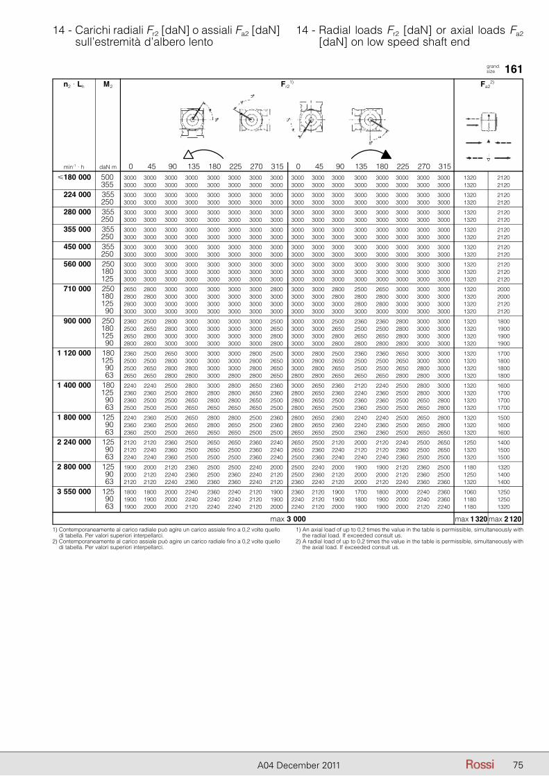
75A04 December 2011
14 - Carichi radiali Fr2 [daN] o assiali Fa2 [daN] sull’estremità d’albero lento
14 - Radial loads Fr2 [daN] or axial loads Fa2 [daN] on low speed shaft end
grand. size 161
1) Contemporaneamente al carico radiale può agire un carico assiale fino a 0,2 volte quello di tabella. Per valori superiori interpellarci.
2) Contemporaneamente al carico assiale può agire un carico radiale fino a 0,2 volte quello di tabella. Per valori superiori interpellarci.
1) An axial load of up to 0,2 times the value in the table is permissible, simultaneously with the radial load. If exceeded consult us.
2) A radial load of up to 0,2 times the value in the table is permissible, simultaneously with the axial load. If exceeded consult us.
n2 · Lh M2 Fr21) Fa2
2)
min-1 · h daN m 0 45 90 135 180 225 270 315 0 45 90 135 180 225 270 315 �180 000 500 3000 3000 3000 3000 3000 3000 3000 3000 3000 3000 3000 3000 3000 3000 3000 3000 1320 2120 355 3000 3000 3000 3000 3000 3000 3000 3000 3000 3000 3000 3000 3000 3000 3000 3000 1320 2120
224 000 355 3000 3000 3000 3000 3000 3000 3000 3000 3000 3000 3000 3000 3000 3000 3000 3000 1320 2120 250 3000 3000 3000 3000 3000 3000 3000 3000 3000 3000 3000 3000 3000 3000 3000 3000 1320 2120
280 000 355 3000 3000 3000 3000 3000 3000 3000 3000 3000 3000 3000 3000 3000 3000 3000 3000 1320 2120 250 3000 3000 3000 3000 3000 3000 3000 3000 3000 3000 3000 3000 3000 3000 3000 3000 1320 2120
355 000 355 3000 3000 3000 3000 3000 3000 3000 3000 3000 3000 3000 3000 3000 3000 3000 3000 1320 2120 250 3000 3000 3000 3000 3000 3000 3000 3000 3000 3000 3000 3000 3000 3000 3000 3000 1320 2120
450 000 355 3000 3000 3000 3000 3000 3000 3000 3000 3000 3000 3000 3000 3000 3000 3000 3000 1320 2120 250 3000 3000 3000 3000 3000 3000 3000 3000 3000 3000 3000 3000 3000 3000 3000 3000 1320 2120
560 000 250 3000 3000 3000 3000 3000 3000 3000 3000 3000 3000 3000 3000 3000 3000 3000 3000 1320 2120 180 3000 3000 3000 3000 3000 3000 3000 3000 3000 3000 3000 3000 3000 3000 3000 3000 1320 2120 125 3000 3000 3000 3000 3000 3000 3000 3000 3000 3000 3000 3000 3000 3000 3000 3000 1320 2120
710 000 250 2650 2800 3000 3000 3000 3000 3000 2800 3000 3000 2800 2500 2650 3000 3000 3000 1320 2000 180 2800 2800 3000 3000 3000 3000 3000 3000 3000 3000 2800 2800 2800 3000 3000 3000 1320 2000 125 2800 3000 3000 3000 3000 3000 3000 3000 3000 3000 3000 2800 2800 3000 3000 3000 1320 2120 90 3000 3000 3000 3000 3000 3000 3000 3000 3000 3000 3000 3000 3000 3000 3000 3000 1320 2120
900 000 250 2360 2500 2800 3000 3000 3000 3000 2500 3000 3000 2500 2360 2360 2800 3000 3000 1320 1800 180 2500 2650 2800 3000 3000 3000 3000 2650 3000 3000 2650 2500 2500 2800 3000 3000 1320 1900 125 2650 2800 3000 3000 3000 3000 3000 2800 3000 3000 2800 2650 2650 2800 3000 3000 1320 1900 90 2800 2800 3000 3000 3000 3000 3000 2800 3000 3000 2800 2800 2800 2800 3000 3000 1320 1900
1 120 000 180 2360 2500 2650 3000 3000 3000 2800 2500 3000 2800 2500 2360 2360 2650 3000 3000 1320 1700 125 2500 2500 2800 3000 3000 3000 2800 2650 3000 2800 2650 2500 2500 2650 3000 3000 1320 1800 90 2500 2650 2800 2800 3000 3000 2800 2650 3000 2800 2650 2500 2500 2650 2800 3000 1320 1800 63 2650 2650 2800 2800 3000 2800 2800 2650 2800 2800 2650 2650 2650 2800 2800 3000 1320 1800
1 400 000 180 2240 2240 2500 2800 3000 2800 2650 2360 3000 2650 2360 2120 2240 2500 2800 3000 1320 1600 125 2360 2360 2500 2800 2800 2800 2650 2360 2800 2650 2360 2240 2360 2500 2800 3000 1320 1700 90 2360 2500 2500 2650 2800 2800 2650 2500 2800 2650 2500 2360 2360 2500 2650 2800 1320 1700 63 2500 2500 2500 2650 2650 2650 2650 2500 2800 2650 2500 2360 2500 2500 2650 2800 1320 1700
1 800 000 125 2240 2360 2500 2650 2800 2800 2500 2360 2800 2650 2360 2240 2240 2500 2650 2800 1320 1500 90 2360 2360 2500 2650 2800 2650 2500 2360 2800 2650 2360 2240 2360 2500 2650 2800 1320 1600 63 2360 2500 2500 2650 2650 2650 2500 2500 2650 2650 2500 2360 2360 2500 2650 2650 1320 1600
2 240 000 125 2120 2120 2360 2500 2650 2650 2360 2240 2650 2500 2120 2000 2120 2240 2500 2650 1250 1400 90 2120 2240 2360 2500 2650 2500 2360 2240 2650 2360 2240 2120 2120 2360 2500 2650 1320 1500 63 2240 2240 2360 2500 2500 2500 2360 2240 2500 2360 2240 2240 2240 2360 2500 2500 1320 1500
2 800 000 125 1900 2000 2120 2360 2500 2500 2240 2000 2500 2240 2000 1900 1900 2120 2360 2500 1180 1320 90 2000 2120 2240 2360 2500 2360 2240 2120 2500 2360 2120 2000 2000 2120 2360 2500 1250 1400 63 2120 2120 2240 2360 2360 2360 2240 2120 2360 2240 2120 2000 2120 2240 2360 2360 1320 1400
3 550 000 125 1800 1800 2000 2240 2360 2240 2120 1900 2360 2120 1900 1700 1800 2000 2240 2360 1060 1250 90 1900 1900 2000 2240 2240 2240 2120 1900 2240 2120 1900 1800 1900 2000 2240 2360 1180 1250 63 1900 2000 2000 2120 2240 2240 2120 2000 2240 2120 2000 1900 1900 2000 2120 2240 1180 1320
max 1 320 max 2 120max 3 000
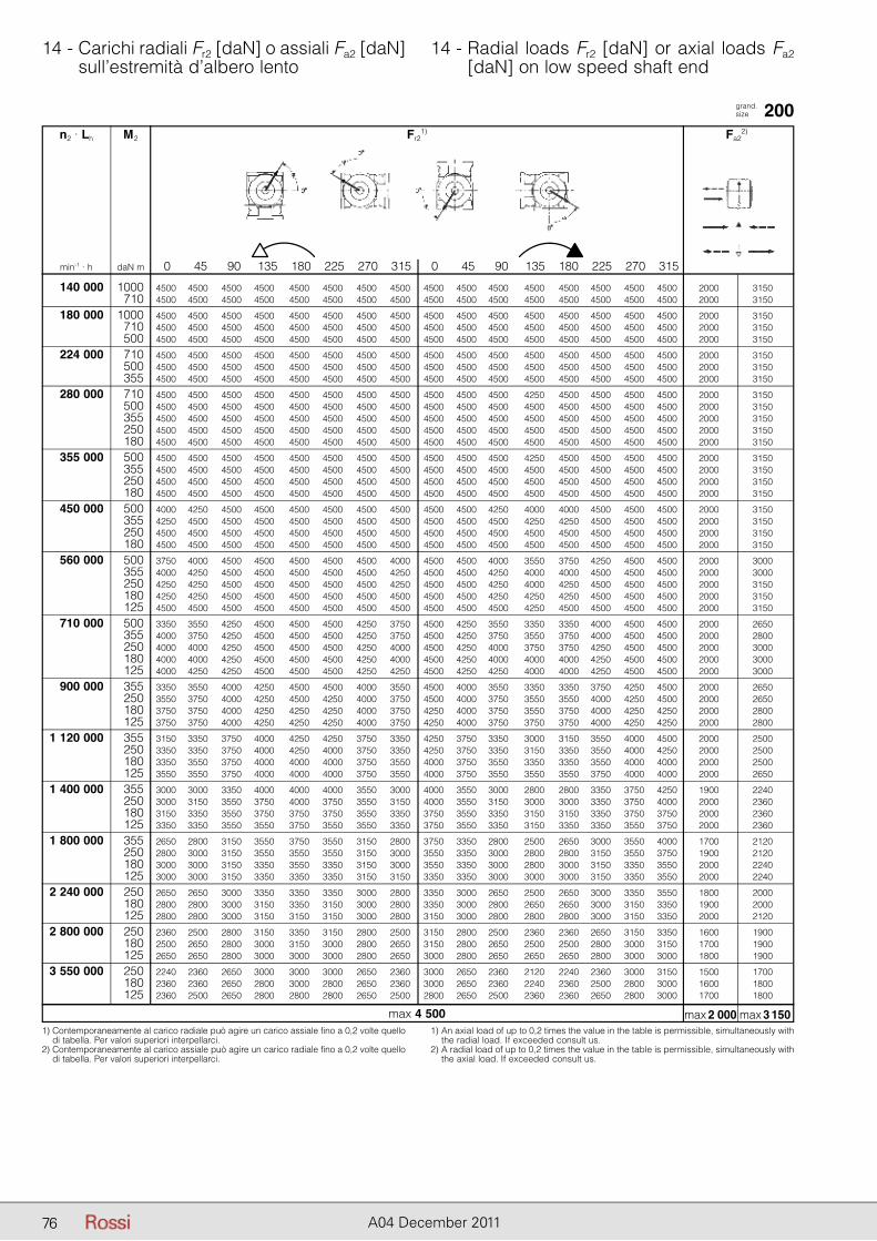
76 A04 December 2011
14 - Carichi radiali Fr2 [daN] o assiali Fa2 [daN] sull’estremità d’albero lento
14 - Radial loads Fr2 [daN] or axial loads Fa2 [daN] on low speed shaft end
grand. size 200
1) Contemporaneamente al carico radiale può agire un carico assiale fino a 0,2 volte quello di tabella. Per valori superiori interpellarci.
2) Contemporaneamente al carico assiale può agire un carico radiale fino a 0,2 volte quello di tabella. Per valori superiori interpellarci.
1) An axial load of up to 0,2 times the value in the table is permissible, simultaneously with the radial load. If exceeded consult us.
2) A radial load of up to 0,2 times the value in the table is permissible, simultaneously with the axial load. If exceeded consult us.
n2 · Lh M2 Fr21) Fa2
2)
min-1 · h daN m 0 45 90 135 180 225 270 315 0 45 90 135 180 225 270 315
140 000 1000 4500 4500 4500 4500 4500 4500 4500 4500 4500 4500 4500 4500 4500 4500 4500 4500 2000 3150 710 4500 4500 4500 4500 4500 4500 4500 4500 4500 4500 4500 4500 4500 4500 4500 4500 2000 3150
180 000 1000 4500 4500 4500 4500 4500 4500 4500 4500 4500 4500 4500 4500 4500 4500 4500 4500 2000 3150 710 4500 4500 4500 4500 4500 4500 4500 4500 4500 4500 4500 4500 4500 4500 4500 4500 2000 3150 500 4500 4500 4500 4500 4500 4500 4500 4500 4500 4500 4500 4500 4500 4500 4500 4500 2000 3150
224 000 710 4500 4500 4500 4500 4500 4500 4500 4500 4500 4500 4500 4500 4500 4500 4500 4500 2000 3150 500 4500 4500 4500 4500 4500 4500 4500 4500 4500 4500 4500 4500 4500 4500 4500 4500 2000 3150 355 4500 4500 4500 4500 4500 4500 4500 4500 4500 4500 4500 4500 4500 4500 4500 4500 2000 3150
280 000 710 4500 4500 4500 4500 4500 4500 4500 4500 4500 4500 4500 4250 4500 4500 4500 4500 2000 3150 500 4500 4500 4500 4500 4500 4500 4500 4500 4500 4500 4500 4500 4500 4500 4500 4500 2000 3150 355 4500 4500 4500 4500 4500 4500 4500 4500 4500 4500 4500 4500 4500 4500 4500 4500 2000 3150 250 4500 4500 4500 4500 4500 4500 4500 4500 4500 4500 4500 4500 4500 4500 4500 4500 2000 3150 180 4500 4500 4500 4500 4500 4500 4500 4500 4500 4500 4500 4500 4500 4500 4500 4500 2000 3150
355 000 500 4500 4500 4500 4500 4500 4500 4500 4500 4500 4500 4500 4250 4500 4500 4500 4500 2000 3150 355 4500 4500 4500 4500 4500 4500 4500 4500 4500 4500 4500 4500 4500 4500 4500 4500 2000 3150 250 4500 4500 4500 4500 4500 4500 4500 4500 4500 4500 4500 4500 4500 4500 4500 4500 2000 3150 180 4500 4500 4500 4500 4500 4500 4500 4500 4500 4500 4500 4500 4500 4500 4500 4500 2000 3150
450 000 500 4000 4250 4500 4500 4500 4500 4500 4500 4500 4500 4250 4000 4000 4500 4500 4500 2000 3150 355 4250 4500 4500 4500 4500 4500 4500 4500 4500 4500 4500 4250 4250 4500 4500 4500 2000 3150 250 4500 4500 4500 4500 4500 4500 4500 4500 4500 4500 4500 4500 4500 4500 4500 4500 2000 3150 180 4500 4500 4500 4500 4500 4500 4500 4500 4500 4500 4500 4500 4500 4500 4500 4500 2000 3150
560 000 500 3750 4000 4500 4500 4500 4500 4500 4000 4500 4500 4000 3550 3750 4250 4500 4500 2000 3000 355 4000 4250 4500 4500 4500 4500 4500 4250 4500 4500 4250 4000 4000 4500 4500 4500 2000 3000 250 4250 4250 4500 4500 4500 4500 4500 4250 4500 4500 4250 4000 4250 4500 4500 4500 2000 3150 180 4250 4250 4500 4500 4500 4500 4500 4500 4500 4500 4250 4250 4250 4500 4500 4500 2000 3150 125 4500 4500 4500 4500 4500 4500 4500 4500 4500 4500 4500 4250 4500 4500 4500 4500 2000 3150
710 000 500 3350 3550 4250 4500 4500 4500 4250 3750 4500 4250 3550 3350 3350 4000 4500 4500 2000 2650 355 4000 3750 4250 4500 4500 4500 4250 3750 4500 4250 3750 3550 3750 4000 4500 4500 2000 2800 250 4000 4000 4250 4500 4500 4500 4250 4000 4500 4250 4000 3750 3750 4250 4500 4500 2000 3000 180 4000 4000 4250 4500 4500 4500 4250 4000 4500 4250 4000 4000 4000 4250 4500 4500 2000 3000 125 4000 4250 4250 4500 4500 4500 4250 4250 4500 4250 4250 4000 4000 4250 4500 4500 2000 3000
900 000 355 3350 3550 4000 4250 4500 4500 4000 3550 4500 4000 3550 3350 3350 3750 4250 4500 2000 2650 250 3550 3750 4000 4250 4500 4250 4000 3750 4500 4000 3750 3550 3550 4000 4250 4500 2000 2650 180 3750 3750 4000 4250 4250 4250 4000 3750 4250 4000 3750 3550 3750 4000 4250 4250 2000 2800 125 3750 3750 4000 4250 4250 4250 4000 3750 4250 4000 3750 3750 3750 4000 4250 4250 2000 2800
1 120 000 355 3150 3350 3750 4000 4250 4250 3750 3350 4250 3750 3350 3000 3150 3550 4000 4500 2000 2500 250 3350 3350 3750 4000 4250 4000 3750 3350 4250 3750 3350 3150 3350 3550 4000 4250 2000 2500 180 3350 3550 3750 4000 4000 4000 3750 3550 4000 3750 3550 3350 3350 3550 4000 4000 2000 2500 125 3550 3550 3750 4000 4000 4000 3750 3550 4000 3750 3550 3550 3550 3750 4000 4000 2000 2650
1 400 000 355 3000 3000 3350 4000 4000 4000 3550 3000 4000 3550 3000 2800 2800 3350 3750 4250 1900 2240 250 3000 3150 3550 3750 4000 3750 3550 3150 4000 3550 3150 3000 3000 3350 3750 4000 2000 2360 180 3150 3350 3550 3750 3750 3750 3550 3350 3750 3550 3350 3150 3150 3350 3750 3750 2000 2360 125 3350 3350 3550 3550 3750 3550 3550 3350 3750 3550 3350 3150 3350 3350 3550 3750 2000 2360
1 800 000 355 2650 2800 3150 3550 3750 3550 3150 2800 3750 3350 2800 2500 2650 3000 3550 4000 1700 2120 250 2800 3000 3150 3550 3550 3550 3150 3000 3550 3350 3000 2800 2800 3150 3550 3750 1900 2120 180 3000 3000 3150 3350 3550 3350 3150 3000 3550 3350 3000 2800 3000 3150 3350 3550 2000 2240 125 3000 3000 3150 3350 3350 3350 3150 3150 3350 3350 3000 3000 3000 3150 3350 3550 2000 2240
2 240 000 250 2650 2650 3000 3350 3350 3350 3000 2800 3350 3000 2650 2500 2650 3000 3350 3550 1800 2000 180 2800 2800 3000 3150 3350 3150 3000 2800 3350 3000 2800 2650 2650 3000 3150 3350 1900 2000 125 2800 2800 3000 3150 3150 3150 3000 2800 3150 3000 2800 2800 2800 3000 3150 3350 2000 2120
2 800 000 250 2360 2500 2800 3150 3350 3150 2800 2500 3150 2800 2500 2360 2360 2650 3150 3350 1600 1900 180 2500 2650 2800 3000 3150 3000 2800 2650 3150 2800 2650 2500 2500 2800 3000 3150 1700 1900 125 2650 2650 2800 3000 3000 3000 2800 2650 3000 2800 2650 2650 2650 2800 3000 3000 1800 1900
3 550 000 250 2240 2360 2650 3000 3000 3000 2650 2360 3000 2650 2360 2120 2240 2360 3000 3150 1500 1700 180 2360 2360 2650 2800 3000 2800 2650 2360 3000 2650 2360 2240 2360 2500 2800 3000 1600 1800 125 2360 2500 2650 2800 2800 2800 2650 2500 2800 2650 2500 2360 2360 2650 2800 3000 1700 1800
max 2 000 max 3 150max 4 500
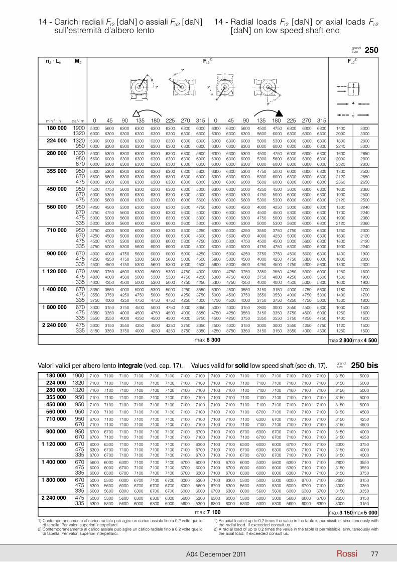
77A04 December 2011
14 - Carichi radiali Fr2 [daN] o assiali Fa2 [daN] sull’estremità d’albero lento
14 - Radial loads Fr2 [daN] or axial loads Fa2 [daN] on low speed shaft end
grand. size 250
1) Contemporaneamente al carico radiale può agire un carico assiale fino a 0,2 volte quello di tabella. Per valori superiori interpellarci.
2) Contemporaneamente al carico assiale può agire un carico radiale fino a 0,2 volte quello di tabella. Per valori superiori interpellarci.
1) An axial load of up to 0,2 times the value in the table is permissible, simultaneously with the radial load. If exceeded consult us.
2) A radial load of up to 0,2 times the value in the table is permissible, simultaneously with the axial load. If exceeded consult us.
n2 · Lh M2 Fr21) Fa2
2)
min-1 · h daN m 0 45 90 135 180 225 270 315 0 45 90 135 180 225 270 315
grand. size 250 bisValori validi per albero lento integrale (ved. cap. 17). Values valid for solid low speed shaft (see ch. 17).
180 000 1900 5000 5600 6300 6300 6300 6300 6300 6000 6300 6300 5600 4500 4750 6300 6300 6300 1400 3000 1320 6000 6300 6300 6300 6300 6300 6300 6300 6300 6300 6300 5600 6000 6300 6300 6300 2000 3000
224 000 1320 5300 6000 6300 6300 6300 6300 6300 6000 6300 6300 6000 5000 5300 6300 6300 6300 1800 2800 950 6000 6300 6300 6300 6300 6300 6300 6300 6300 6300 6300 6000 6000 6300 6300 6300 2240 3000
280 000 1320 5000 5300 6300 6300 6300 6300 6300 5600 6300 6300 5300 4500 4750 6000 6300 6300 1600 2650 950 5600 6000 6300 6300 6300 6300 6300 6000 6300 6300 6000 5300 5600 6300 6300 6300 2000 2800 670 6000 6300 6300 6300 6300 6300 6300 6300 6300 6300 6300 6000 6000 6300 6300 6300 2320 2800
355 000 950 5000 5300 6300 6300 6300 6300 6300 5600 6300 6300 5300 4750 5000 6000 6300 6300 1800 2500 670 5600 5600 6300 6300 6300 6300 6300 6000 6300 6300 6000 5300 6000 6300 6300 6300 2120 2650 475 6000 6000 6300 6300 6300 6300 6300 6000 6300 6300 6000 5600 6000 6300 6300 6300 2360 2650
450 000 950 4500 4750 5600 6300 6300 6300 6300 5000 6300 6300 5000 4250 4500 5600 6300 6300 1600 2360 670 5000 5300 6000 6300 6300 6300 6300 5300 6300 6300 5300 4750 5000 6000 6300 6300 1900 2500 475 5300 5600 6000 6300 6300 6300 6000 5600 6300 6300 5600 5300 5300 6000 6300 6300 2120 2500
560 000 950 4250 4500 5300 6300 6300 6300 5600 4750 6300 6000 4500 4000 4250 5000 6300 6300 1500 2240 670 4750 4750 5600 6300 6300 6300 5600 5000 6300 6000 5000 4500 4500 5300 6300 6300 1700 2240 475 5000 5000 5600 6000 6300 6300 5600 5300 6300 6000 5300 4750 5000 5600 6000 6300 1900 2360 335 5300 5300 5600 6000 6300 6000 5600 5300 6300 6000 5300 5000 5300 5600 6000 6300 2120 2360
710 000 950 3750 4000 5000 6000 6300 6300 5300 4250 6300 5300 4250 3550 3750 4750 6000 6300 1250 2000 670 4250 4500 5000 6000 6300 6000 5300 4500 6300 5600 4500 4000 4250 5000 6000 6300 1600 2120 475 4500 4750 5300 6000 6000 6000 5300 4750 6000 5300 4750 4500 4500 5000 5600 6300 1800 2120 335 4750 5000 5300 5600 6000 6000 5300 5000 6000 5300 5000 4750 4750 5300 5600 6000 1900 2240
900 000 670 4000 4000 4750 5600 6000 6000 5000 4250 6000 5000 4250 3750 3750 4500 5600 6300 1400 1900 475 4250 4250 4750 5300 5600 5600 5000 4500 5600 5000 4500 4000 4250 4750 5300 6000 1600 2000 335 4500 4500 4750 5300 5600 5300 5000 4500 5600 5000 4500 4250 4500 4750 5300 5600 1800 2000
1 120 000 670 3550 3750 4500 5300 5600 5300 4750 4000 5600 4750 3750 3350 3550 4250 5300 6000 1250 1800 475 4000 4000 4500 5000 5300 5300 4750 4250 5300 4750 4000 3750 4000 4250 5000 5600 1500 1900 335 4000 4250 4500 5000 5300 5000 4750 4250 5300 4750 4250 4000 4000 4500 5000 5300 1600 1900
1 400 000 670 3350 3550 4000 5000 5300 5000 4250 3550 5300 4500 3550 3150 3150 4000 4750 5600 1180 1700 475 3550 3750 4250 4750 5000 5000 4250 3750 5000 4500 3750 3550 3550 4000 4750 5300 1400 1700 335 3750 4000 4250 4750 4750 4750 4250 4000 4750 4500 4000 3750 3750 4250 4750 5000 1500 1800
1 800 000 670 3000 3150 3750 4500 5000 4750 4000 3350 5000 4000 3150 2800 3000 3550 4500 5300 1000 1500 475 3350 3350 4000 4500 4750 4500 4000 3550 4750 4250 3550 3150 3350 3750 4500 5000 1250 1600 335 3550 3550 4000 4250 4500 4500 4000 3750 4500 4250 3750 3350 3550 3750 4250 4750 1400 1600
2 240 000 475 3000 3150 3550 4250 4500 4250 3750 3350 4500 4000 3150 3000 3000 3550 4250 4750 1120 1500 335 3150 3350 3750 4000 4250 4250 3750 3350 4250 3750 3350 3150 3150 3550 4000 4500 1250 1500
180 000 1900 7100 7100 7100 7100 7100 7100 7100 7100 7100 7100 7100 7100 7100 7100 7100 7100 3150 5000
224 000 1320 7100 7100 7100 7100 7100 7100 7100 7100 7100 7100 7100 7100 7100 7100 7100 7100 3150 5000
280 000 1320 7100 7100 7100 7100 7100 7100 7100 7100 7100 7100 7100 7100 7100 7100 7100 7100 3150 5000
355 000 950 7100 7100 7100 7100 7100 7100 7100 7100 7100 7100 7100 7100 7100 7100 7100 7100 3150 5000
450 000 950 7100 7100 7100 7100 7100 7100 7100 7100 7100 7100 7100 7100 7100 7100 7100 7100 3150 5000
560 000 950 7100 7100 7100 7100 7100 7100 7100 7100 7100 7100 7100 6700 7100 7100 7100 7100 3150 4500
710 000 950 6700 7100 7100 7100 7100 7100 7100 7100 7100 7100 7100 6300 6700 7100 7100 7100 3150 4250 670 7100 7100 7100 7100 7100 7100 7100 7100 7100 7100 7100 7100 7100 7100 7100 7100 3150 4500
900 000 950 6700 6700 7100 7100 7100 7100 7100 6700 7100 7100 6700 6300 6700 7100 7100 7100 3150 4000 670 6700 7100 7100 7100 7100 7100 7100 7100 7100 7100 7100 6700 6700 7100 7100 7100 3150 4250
1 120 000 670 6000 6300 7100 7100 7100 7100 7100 6300 7100 7100 6300 6000 6000 6700 7100 7100 3000 3750 475 6300 6700 7100 7100 7100 7100 7100 6700 7100 7100 6700 6300 6300 6700 7100 7100 3150 4000 335 6700 6700 7100 7100 7100 7100 7100 6700 7100 7100 6700 6700 6700 7100 7100 7100 3150 4000
1 400 000 670 5600 6000 6300 7100 7100 7100 6700 6000 7100 6700 6000 5300 5600 6300 7100 7100 2800 3550 475 6000 6000 6700 7100 7100 7100 6700 6000 7100 6700 6000 6000 6000 6300 7100 7100 3150 3550 335 6000 6300 6700 7100 7100 7100 6700 6300 7100 6700 6300 6000 6000 6300 7100 7100 3150 3750
1 800 000 670 5000 5300 6000 6700 7100 6700 6000 5300 7100 6300 5300 5000 5000 6000 6700 7100 2650 3150 475 5300 5600 6000 6700 6700 6700 6000 5600 6700 6300 5600 5300 5300 6000 6700 7100 3000 3350 335 5600 5600 6000 6300 6700 6700 6000 6000 6700 6300 6000 5600 5600 6000 6300 6700 3150 3350
2 240 000 475 5000 5300 5600 6300 6300 6300 5600 5300 6300 6000 5300 5000 5000 5600 6000 6700 2650 3150 335 5300 5300 5600 6000 6300 6000 5600 5300 6300 6000 5300 5300 5300 5600 6000 6300 3000 3150
max 2 800 max 4 500max 6 300
max 3 150 max 5 000max 7 100
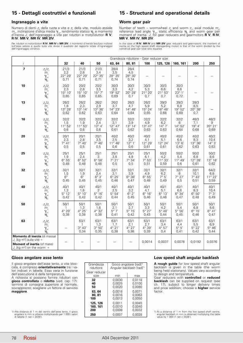
78 A04 December 2011
15 - Dettagli costruttivi e funzionali 15 - Structural and operational details
Ingranaggio a viteNumero di denti z2 della ruota a vite e z1 della vite, modulo assiale mx, inclinazione d’elica media �m, rendimento statico �s e momento d’inerzia J1 dell’ingranaggio a vite per riduttori e motoriduttori R V,R IV, MR V, MR IV, MR 2IV.Per riduttori e motoriduttori R IV, MR IV e MR 2IV, il momento d’inerzia (escluso motore) sull’asse veloce è quello sulla vite diviso il quadrato del rapporto totale d’ingranaggio dell’ingranaggio cilindrico.
Worm gear pairNumber of teeth – wormwheel z2 and worm z1, axial module mx, reference lead angle �m, static efficiency �s and worm gear pair moment of inertia J1 for gear reducers and gearmotors R V, R IV, MR V, MR IV, MR 2IV.In the case of R IV, MR IV and MR 2IV gear reducers and gearmotors, the moment ofinertia on the high speed shaft (disregarding motor) is that of the worm divided by the cylindrical gear pair total ratio squared.
Gioco angolare asse lentoIl gioco angolare dell’asse lento, a vite bloc-cata, è compreso orientativamente tra i va-lori indicati in tabella. Esso varia in funzione dell’esecuzione e della temperatura.A richiesta si possono fornire riduttori con gioco controllato o ridotto (ved. cap. 17): termine di consegna superiore al normale, sovrapprezzo; scegliere un fattore di servizio maggiore.
1) Alla distanza di 1 m dal centro dell’asse lento, il gioco angolare in mm si ottiene moltiplicando per 1 000 i valori di tabella (1 rad = 3438’).
Low speed shaft angular bac k lashA rough guide for low speed shaft angular backlash is given in the table (the worm being held stationary). Values vary according to design and temperature.Gear reducers with controlled or reduced backlash can be supplied on request (see ch. 17), subject to longer delivery times and price addition; choose a higher service factor.
1) At a distance of 1 m from the low speed shaft centre, angular backlash in mm is obtained multiplying the table value by 1 000 (1 rad = 3438’).
Grandezza Gioco angolare [rad]1)
riduttore Angular backlash [rad]1)
Gear reducer size min max 32 0,0030 0,0118 40 0,0025 0,0100 50 0,0020 0,0080 63, 64 0,0018 0,0071 80, 81 0,0016 0,0063 100 0,0013 0,0050 125, 126 0,0011 0,0045 160, 161 0,0010 0,0040 200 0,0008 0,0032 250 0,0007 0,0028
Grandezza riduttore - Gear reducer size i 32 40 50 63, 64 80, 81 100 125, 126 160, 161 200 250
7 z2/z1 21/3 21/3 21/3 28/4 28/4 mx 2,2 2,8 3,4 3,5 4,5 �m 22° 29’ 22° 29’ 22° 35’ 28° 35’ 28° 30’ – – – – – �s 0,71 0,71 0,71 0,74 0,74
10 z2/z1 20/2 20/2 20/2 30/3 30/3 30/3 30/3 30/3 mx 2,3 2,8 3,5 3,3 4,2 5,3 6,6 8,6 �m 15° 10’ 15° 10’ 15° 7’ 19° 52’ 20° 28’ 21° 20’ 21° 53’ 23° 1’ – – �s 0,65 0,65 0,65 0,69 0,7 0,7 0,7 0,72
13 z2/z1 26/2 26/2 26/2 26/2 26/2 26/2 39/3 39/3 39/3 mx 1,8 2,3 2,9 3,7 4,7 5,9 5,2 6,8 8,5 �m 13° 28’ 13° 14’ 13° 36’ 14° 23’ 14° 48’ 15° 24’ 18° 48’ 19° 52’ 20° 38’ – �s 0,62 0,62 0,63 0,64 0,64 0,65 0,68 0,69 0,7
16 z2/z1 32/2 32/2 32/2 32/2 32/2 32/2 32/2 32/2 48/3 48/3 mx 1,5 1,9 2,4 3,1 3,9 4,9 6,2 8 7,1 9 �m 11° 52’ 11° 53’ 12° 4’ 12° 47’ 13° 14’ 13° 47’ 14° 7’ 14° 52’ 19° 4’ 20° 21’ �s 0,6 0,6 0,6 0,61 0,62 0,63 0,63 0,64 0,68 0,69
20 z2/z1 20/1 20/1 20/1 40/2 40/2 40/2 40/2 40/2 40/2 40/2 mx 2,3 2,8 3,5 2,5 3,2 4,1 5,1 6,6 8,3 10,4 �m 7° 41’ 7° 40’ 7° 46’ 11° 46’ 12° 1’ 12° 29’ 12° 24’ 13° 6’ 13° 36’ 14° 3’ �s 0,5 0,5 0,5 0,6 0,6 0,61 0,61 0,62 0,63 0,63
25 z2/z1 25/1 25/1 25/1 25/1 25/1 25/1 50/2 50/2 50/2 50/2 mx 1,9 2,4 3 3,8 4,8 6,1 4,2 5,4 6,8 8,6 �m 6° 55’ 6° 52’ 6° 58’ 7° 21’ 7° 34’ 7° 53’ 11° 33’ 11° 49’ 12° 28’ 13° 18’ �s 0,48 0,48 0,48 0,5 0,5 0,51 0,59 0,6 0,61 0,62
32 z2/z1 32/1 32/1 32/1 32/1 32/1 32/1 32/1 32/1 32/1 64/2 mx 1,5 1,9 2,4 3,1 3,9 4,9 6,2 8 10,1 6,8 �m 6° 6° 6° 3’ 6° 25’ 6° 38’ 6° 55’ 7° 5’ 7° 27’ 7° 43’ 11° 22’ �s 0,45 0,45 0,45 0,46 0,47 0,48 0,49 0,5 0,51 0,59
40 z2/z1 40/1 40/1 40/1 40/1 40/1 40/1 40/1 40/1 40/1 40/1 mx 1,3 1,6 2 2,5 3,2 4,1 5,1 6,6 8,3 10,4 �m 5° 12’ 5° 10’ 5° 16’ 5° 54’ 6° 2’ 6° 16’ 6° 13’ 6° 34’ 6° 50’ 7° 3’ �s 0,42 0,42 0,42 0,44 0,45 0,46 0,46 0,47 0,48 0,49
50 z2/z1 50/1 50/1 50/1 50/1 50/1 50/1 50/1 50/1 50/1 50/1 mx 1 1,3 1,6 2,1 2,7 3,3 4,2 5,4 6,8 8,6 �m 4° 29’ 4° 25’ 4° 32’ 5° 7’ 5° 15’ 5° 27’ 5° 48’ 5° 56’ 6° 15’ 6° 41’ �s 0,38 0,38 0,38 0,41 0,42 0,43 0,44 0,45 0,46 0,47
63 z2/z1 63/1 63/1 63/1 63/1 63/1 63/1 63/1 63/1 63/1 mx 1 1,3 1,7 2,1 2,7 3,4 4,4 5,5 6,9 �m – 3° 43’ 3° 50’ 4° 21’ 4° 27’ 4° 39’ 4° 57’ 5° 5’ 5° 22’ 5° 46’ �s 0,34 0,35 0,38 0,38 0,39 0,4 0,41 0,42 0,44 Momento di inerzia (di massa) J1 [kg m2] sulla vite ≈
– – – – – 0,0014 0,0037 0,0078 0,0192 0,0376 Moment of inertia (of mass) J1 [kg m2] on the worm ≈
78
79A04 December 2011
15 - Dettagli costruttivi e funzionali 15 - Structural and operational details
Rendimento � Il rendimento � è dato dal rapporto PN2 / PN1 per riduttori (cap. 7) e P2 / P1 per i motoriduttori (cap. 9). I valori del rendimento così calcolati sono validi per condizioni di lavoro normali, vite motrice e lubrificazione corretta, dopo un buon rodaggio (ved. cap. 16) e con un carico vicino al valore nominale.Il rendimento è più basso (di circa il 12% per viti con z1 = 1; 6% per viti con z1 = 2; 3% per viti con z1 = 3) nelle prime ore di funziona-mento (circa 50) e, in generale, ad ogni avviamento a freddo.Allo spunto il rendimento «statico» �s (ved. tabella al paragrafo precedente) è molto più basso di � (per il fatto che a velocità 0 si deve vincere l’attrito di «primo distacco»); all’aumentare della velo-cità il rendimento aumenta fino a raggiungere il valore di catalogo.Il rendimento inverso �inv, che si ha quando la ruota a vite è motri-ce, è sempre inferiore a �. Può essere calcolato, con una buona approssimazione, con la formula:
�inv ≈ 2 – 1 / �; analogamente: �s inv ≈ 2 – 1 / �s
IrreversibilitàUn riduttore o motoriduttore a vite è dinamicamente irreversibile (cessa istantaneamente di ruotare quando sull’asse della vite non ci sono più cause che mantengano in rotazione la vite stessa, es.: mo-mento motore, inerzia dovuta alla vite e relativa ventola, motore, volani, giunti, ecc.) quando � � 0,5 in quanto �inv diventa minore di 0.Questa condizione è necessaria quando c’è l’esigenza di arrestare e trattenere il carico, anche senza l’intervento di un freno. In pre-senza di vibrazioni continue l’irreversibilità dinamica può non essere possibile.Un riduttore o motoriduttore è staticamente irreversibile (non è possibile metterlo in rotazione dall’asse lento) quando �s� 0,5.Questa condizione è necessaria quando c’è l’esigenza di mantenere in sosta il carico, in pratica tenuto conto che i rendimenti possono mi-gliorare con il funzionamento è consigliabile che sia �s�0,4 (�m � 5°).In presenza di vibrazioni continue l’irreversibilità statica può non essere possibile.Un riduttore o motoriduttore ha una bassa reversibilità statica (èpossibile metterlo in movimento dall’asse lento con momenti torcen-ti elevati e/o in presenza di vibrazioni) quando 0,5 � �s� 0,6 (7°30’ � �m � 12°).Un riduttore o motoriduttore ha una reversibilità statica completa (è possibile metterlo in movimento dall’asse lento) quanto �s � 0,6(�m � 12°).Questa condizione è consigliabile quando c’è l’esigenza di avviare con facilità il riduttore dall’asse lento.
SovraccarichiPoiché l’ingranaggio a vite è spesso sottoposto a elevati sovraccarichi statici e dinamici, in quanto è particolarmente idoneo a sopportarli, si presenta – più frequentemente che per altri tipi di ingranaggio – la necessità di verificare che il valore di questi sovraccarichi sia sempre inferiore a M2 max (cap. 7).Normalmente si generano sovraccarichi quando si hanno:– avviamenti a pieno carico (specialmente per elevare inerzie e bassi
rapporti di trasmissione), frenature, urti;– casi di riduttori irreversibili o poco reversibili in cui la ruota a vite
diventa motrice per effetto delle inerzie della macchina azionata;– potenza applicata superiore a quella richiesta; altre cause statiche
o dinamiche.Qui di seguito diamo alcune considerazioni generali su questi so vrac-carichi e, per alcuni casi tipici, alcune formule per la loro valutazione.Quando non è possibile valutarli, inserire dispositivi di sicurezza in modo da non superare mai M2 max.
Momento torcente di spuntoQuando l’avviamento è a pieno carico (specialmente per elevate inerzie e bassi rapporti di trasmissione), verificare che M2 max sia maggiore o uguale al momento torcente di spunto il quale può essere calcolato con la formula:
M2 spunto = �M spuntoMN
· M2 disp. – M2 richiesto� JJ + J0 · �
+ M2 richiesto
dove:M2 richiesto è il momento torcente assorbito dalla macchina per lavoro e attriti;M2 disponibile è il momento torcente in uscita dovuto alla potenza nominale del motore;J0 è il momento d’inerzia (di massa) del motore;J è il momento d’inerzia (di massa) esterno (riduttore, giunti, macchina azionata) in kg m2, riferito all’asse del motore;per gli altri simboli ved. cap. 2b.NOTA: quando si vuole verificare che il momento torcente di spunto sia sufficientemente elevato per l’avviamento, considerare, nella valutazione di M2 disponibile il rendimento �s, e nella valutazione di M2 richiesto, eventuali attriti di primo distacco.
Efficiency � Efficiency � is derived from the PN2 / PN1 ratio in the case of gear reducers (ch. 7) and P2 / P1 in the case of gearmotors (ch. 9). The values obtained will be valid assuming normal working conditions, worm operating as driving member, proper lubrication, adequate running-in (ch. 16), and a load near to the nominal value.During the initial working period (about 50 hours) and generally at every cold start, efficiency will be lower (by about 12% for worms with z1 = 1; 6% for worms with z1 = 2 and 3% for worms with z1 = 3).«Static» efficiency �s on starting (see table in the preceding sec-tion) is much lower than � («starting friction») must be overcome at speed 0); as speed picks up gradually, efficiency will rise correspond-ingly until the catalogue value is reached.Inverse efficiency �inv, – produced by the wormwheel as driver– is always less than �. It can be calculated approximately as fol-lows:
�inv ≈ 2 – 1 / �; likewise: �s inv ≈ 2 – 1 / �s
IrreversibilityA worm gear reducer or gearmotor is dynamically irreversible (that is, it ceases to turn the instant the wormshaft receives no further stimu-lus that would keep the worm itself in rotation e.g. motor torque, iner-tia from the worm and related fan, motor flywheels, couplings, etc.) when � � 0,5 as �inv then drops below 0.This state becomes necessary wherever there is a need for stop-ping and holding the load, even without the aid of a brake. Where continuous vibration occurs, dynamic irreversibility may not be obtainable.A gear reducer or gearmotor is statically irreversible (that is,rotation cannot be imparted by way of the low speed shaft) when �s� 0,5.This is a state necessary to keep the load at standstill; taking into account, however, that efficiency can increase with time spent in opera-tion, it would be advisable to assume �s� 0,4 (�m � 5°).Where continuous vibration occurs, static irreversibility may not be obtainable.A gear reducer or gearmotor has low static reversibility (i.e. rotation may be imparted by way of the low speed shaft with high torque and/or vibration) when 0,5 � �s� 0,6 (7° 30’ � �m � 12°).A gear reducer or gearmotor has complete static reversibility (i.e. rotation may be imparted by way of the low speed shaft) when �s �0,6 (�m � 12°).This state is advisable where there is a need for easy start-up of the gear reducer by way of the low speed shaft.
OverloadsSince worm gear pairs are often subject to high static and dynamic overloads by dint of the fact that they are especially suited to bear them, the need arises – more so than with other gear pairs – for veri-fying that such overloads will always remain lower than M2 max (ch. 7).Overloads are normally generated when one has:– starting on full load (especially for high inertias and low trans-
mission ratios), braking, shocks;– irreversible gear reducers, or gear reducers with low reversibility
in which the wormwheel becomes driver due to driven machine inertia;
– applied power higher than that required; other static or dynamic causes.
The following general observations on overloads are accompanied by some formulae for carrying out evaluations in certain typical instances.Where no evaluation is possible, install safety devices which will keep values within M2max.
Starting torqueWhen starting on full load (especially for high inertias and low trans-mission ratios) verify that M2max is equal to or greater than starting torque, by using the following formula:
M2 start = �M startMN
· M2 available – M2 required� JJ + J0· �
+ M2 required
where:M2 required is torque absorbed by the machine through work and friction;M2 available is output torque derived from the motor’s nominal power rating;J0 is the moment of inertia (of mass) of the motor;J is the external moment of inertia (of mass) in kg m2 (gear reducers, couplings, driven machine) referred to the motor shaft;for other symbols see ch. 2b.NOTE: When seeking to verify that starting torque is sufficiently high for starting, take into account efficiency �s when evaluating M2 available, and starting friction, if any, in evaluating M2 required.
80 A04 December 2011
15 - Dettagli costruttivi e funzionali 15 - Structural and operational details
Arresti di macchine con elevata energia cinetica (elevati mo menti d’inerzia con elevate velocità) senza o con frenature (con motore autofrenante o freno sull’asse della vite)Scegliere sempre un riduttore staticamente reversibile (�s � 0,5); se il motore è autofrenante verificare la sollecitazione di frenatura con la formula:
� M f�s inv
· i + M2 richiesto� JJ + J0 /�s inv
– M2 richiesto � M2 max
dove:M f è il momento frenante di taratura (ved. tabella del cap. 2b).�s inv è il rendimento statico inverso (ved. paragrafo precedente);per gli altri simboli ved. sopra e cap. 1.
Quando non è possibile scegliere un riduttore staticamente reversi-bile (cioè �s � 0,5) occorre che il rallentamento sia sufficientemente dolce (per evitare sollecitazioni troppo elevate al riduttore stesso) in modo che sia:
J2 · �2
10 – M2 � M2 max
dove:J2 [kg m2] è il momento d’inerzia (di massa) della macchina azionata riferito all’asse lento del riduttore;M2 [daN m] è il momento torcente assorbito dalla macchina per lavoro e attriti;�2 [rad/s2] è la decelerazione angolare dell’asse lento; può essere diminuita per mezzo di volani sull’asse della vite, rampe elettriche di decelerazione, diminuzione del momento frenante quando c’è frenatura, ecc.Il valore di �2 può essere valutato sulla base di considerazioni (in sicurezza) teoriche oppure sperimentalmente (per mezzo del tempo e dello spazio di arresto, ecc.). Se il motore è autofrenante �2 può essere valutato (prudenzialmente) con la formula:
�2 = 10 · Mf
J0 · i
in cui si considera il motore a vuoto e sottoposto al momento frenante di taratura Mf[daN m] (ved. tabella del cap. 2b).
Funzionamento con motore autofrenanteTempo di avviamento ta e angolo di rotazione del motore �a1
ta = (J0 + J/�) · n1 [s]; �a1 = ta · n119,1
[rad]
95,5 �M spunto – M2 richiestoi · �
�Tempo di frenatura tf e angolo di rotazione del motore �f1
t f = (J0 + J/�inv) · n1
[s]; �f1 = t f · n119,1
[rad] 95,5 �Mf + M2 richiesto · �inv
i �dove:M spunto [daN m] è il momento torcente di spunto del motore �955 · P1
n1
· M spunto
MN�
(ved. cap. 2b);M f [daN m] è il momento frenante di taratura del motore (ved. cap. 2b);per altri simboli ved. sopra e cap. 1.
La ripetitività di frenatura, con riduttore rodato e a regime termico, al variare della temperatura del freno e dello stato di usura della guarnizione di attrito è – entro i limiti normali del traferro e dell’umi-dità ambiente e con adeguata apparecchiatura elettrica – circa± 0,1 · �f1.Nella fase di riscaldamento (1 � 3 h dalle grandezze piccole alle grandi) i tempi e gli spazi di frenatura tendono ad aumentare fino a stabilizzarsi attorno ai valori corrispondenti ai rendimenti di catalogo.
Durata della guarnizione di attritoOrientativamente il nu mero di frenature ammesso tra due registrazioni è dato dalla formula:
W · 105
M f · �f1
dove:W [MJ] è il lavoro di attrito fra due registrazioni del traferro indicato in tabella; per altri simboli ved. sopra.
Il valore del traferro va da un minimo di 0,25 a un massi-mo di 0,7; orientativamente il numero di registrazioni è 5.
Stopping machines with high kinetic energy (high moments of inertia combined with high speeds) with or without braking (braking applied to wormshaft, or use of brake motor)Select a gear reducer with static reversibility (�s � 0,5); if using a brake motor, verify braking stress with the following formula:
� M f�s inv
· i + M2 required� JJ + J0 /�s inv
– M2 required � M2 max
where:M f is the braking torque setting (see table in ch. 2b).�s inv is static inverse efficiency (see previous heading);for other symbols see above and ch.1.
Where selection of a statically reversible gear reducer is not pos-sible (i.e. �s � 0,5) slowing-down should be sufficiently gradual (avoid-ing application of excessive stress to the unit itself) as to ensure that:
J2 · �2
10 – M2 � M2 max
where:J2 [kg m2] is the moment of inertia (of mass) of the driven machine referred to the gear reducer’s low speed shaft;M2 [daN m] is torque absorbed by the machine through work and friction;�2 [rad/s2] is the low speed shaft’s angular deceleration; this may be reduced by fly-wheel fitted to the wormshaft, electric deceleration ramps, lowering of braking torque when braking systems are in use, etc.�2 may be arrived at theorically (within broadly safe limits) or experimentally (by testing against stopping time and distance etc.).If a brake motor is in use, the following formula may be used for a safe evaluation of �2:
�2 = 10 · Mf
J0 · i
in which the motor is presumed without load and subject to its braking torque settingMf [daN m] (see table in ch. 2b).
Operation with brake motorStating time ta and revolutions of motor �a1
ta = (J0 + J/�) · n1 [s]; �a1 = ta · n119,1
[rad]
95,5 �M start – M2 requiredi · � �
Braking time t f and revolutions of motor �f1
t f = (J0 + J/�inv) · n1 [s]; �f1 = t f · n119,1
[rad]
95,5 �Mf + M2 required · �inv i �
where:M start [daN m] is motor starting torque �955 · P1
n1
· M startMN
� (see ch. 2b);
M f [daN m] is the braking torque setting of the motor (see ch. 2b);for other symbols see above and ch. 1.
With the gear reducer run in and operating at normal running tem-perature – assuming a regular air-gap and ambient humidity and uti-lizing suitable electrical equipment – repetition of the braking action, as affected by variation in temperature of the brake and by the state of wear of friction surface, is approx ± 0,1 · �f1.During warm-up (1 � 3 h, small through to large sizes), braking times and distances tend to increase to the point of stabilizing at or around values corresponding to rated catalogue efficiency.
Duration of friction surfaceAs a rough guide, the number of applications permis-sible between successive adjustments of the air-gap is given by the following formula:
W · 105
M f · �f1
where:W [MJ] is the work of friction between successive adjustments of the air-gap as indicated in the table. For other symbols see above.
The air-gap should measure between 0,25 minimum and 0,7 maximum; as a rough guide, 5 adjustments can be made.
Grandezza motore W
Motor size MJ
63 10,6 71 14 80 18 90 24 100 24 112 45 132 67 160, 180M 90 180L, 200 125
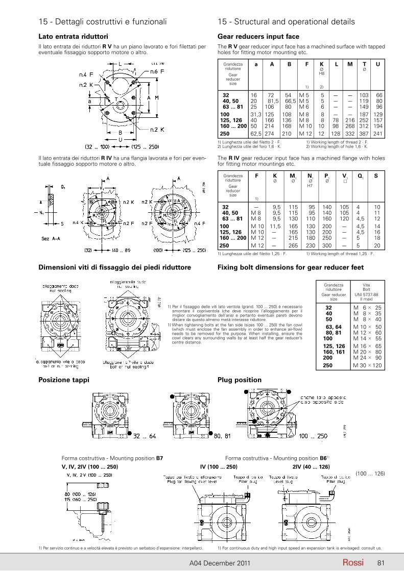
81A04 December 2011
15 - Dettagli costruttivi e funzionali 15 - Structural and operational details
Lato entrata riduttoriIl lato entrata dei riduttori R V ha un piano lavorato e fori filettati per eventuale fissaggio sopporto motore o altro.
Gear reducers input faceThe R V gear reducer input face has a machined surface with tapped holes for fitting motor mounting etc.
Dimensioni viti di fissaggio dei piedi riduttore Fixing bolt dimensions for gear reducer feet
Posizione tappi Plug position
Il lato entrata dei riduttori R IV ha una flangia lavorata e fori per even-tuale fissaggio sopporto motore o altro.
The R IV gear reducer input face has a machined flange with holes for fitting motor mountings etc.
a A B F K L M T U Ø Ø H8
1) 2)
32 16 72 54 M 5 5 – – 103 66 40, 50 20 81,5 66,5 M 5 5 – – 119 80 63 ... 81 25 106 80 M 6 6 – – 149 96 100 31,3 125 108 M 8 8 – – 187 129 125, 126 40 166 136 M 8 8 78 216 252 157 160 ... 200 50 214 168 M 10 10 98 268 312 194 250 62,5 274 210 M 12 12 128 332 387 241
Grandezzariduttore
Gearreducer
size
1) Lunghezza utile del filetto 2 · F.2) Lunghezza utile del foro 1,6 · K.
1) Working length of thread 2 · F.2) Working length of hole 1,6 · K.
F K M1 N1 P1 V1 Q1 S Ø Ø Ø Ø � H7
1)
32 – 9,5 115 95 140 105 4 10 40, 50 M 8 9,5 115 95 140 105 4 11 63 ... 81 M 8 9,5 130 110 160 120 4,5 12 100 M 10 11,5 165 130 200 – 4,5 14 125, 126 M 10 – 165 130 200 – 4,5 16 160 ... 200 M 12 – 215 180 250 – 5 18 250 M 12 – 265 230 300 – 5 20
Grandezzariduttore
Gearreducer
size
1) Lunghezza utile del filetto 1,25 · F. 1) Working length of thread 1,25 · F.
1) Per il fissaggio delle viti lato ventola (grand. 100 ... 250) è necessario smontare il copriventola (che deve ricoprire l’alloggiamento per il miglior convogliamento dell’aria) e pertanto eventuali pareti devono distare da questo almeno metà interasse riduttore.
1) When tightening bolts at the fan side (sizes 100 ... 250) the fan cowl (which must enclose the fan assembly in order to enhance air-flow) needs to be removed for the purpose. When installing, ensure the cowl clears any surrounding walls by at least half the gear reducer’s centre distance.
Grandezza Vite riduttore Bolt Gear reducer UNI 5737-88 size (l max)
32 M 6 � 25 40 M 8 � 35 50 M 8 � 40 63, 64 M 10 � 50 80, 81 M 12 � 60 100 M 14 � 55 125, 126 M 16 � 65 160, 161 M 20 � 80 200 M 24 � 90 250 M 30 � 120
Forma costruttiva - Mounting position B7 Forma costruttiva - Mounting position B61)
V, IV, 2IV (100 ... 250) IV (100 ... 250) 2IV (40 ... 126)
1) Per servizio continuo e a velocità elevata è previsto un serbatoio d’espansione: interpellarci. 1) For continuous duty and high input speed an expansion tank is envisaged: consult us.
(100 ... 126)
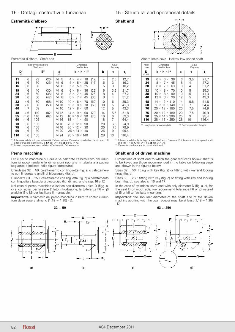
82 A04 December 2011
15 - Dettagli costruttivi e funzionali 15 - Structural and operational details
Estremità d’albero Shaft end
Estremità d’albero - Shaft end Albero lento cavo - Hollow low speed shaft
Estremità d’albero Linguetta Cava Shaft end Parallel key Keyway
D1) E2) d b � h � l2) b t t1 Ø Ø
11 j 6 23 (20) M 5 4 � 4 � 18 (12) 4 2,5 12,7 14 j 6 30 (25) M 6 5 � 5 � 25 (16) 5 3 16,2 16 j 6 30 M 6 5 � 5 � 25 5 3 18,2 19 j 6 40 (30) M 6 6 � 6 � 36 (25) 6 3,5 21,7 24 j 6 50 (36) M 8 8 � 7 � 45 (25) 8 4 27,2 28 j 6 60 (42) M 8 8 � 7 � 45 (36) 8 4 31,2 32 k 6 80 (58) M 10 10 � 8 � 70 (50) 10 5 35,3 38 k 6 80 (58) M 10 10 � 8 � 70 (50) 10 5 41,3 40 h 7 58 M 10 12 � 8 � 50 12 5 43,3 48 k 6 110 (82) M 12 14 � 9 � 90 (70) 14 5,5 51,8 55 m 6 110 (82) M 12 16 � 10 � 90 (70) 16 6 59,3 60 m 6 105 M 16 18 � 11 � 90 18 7 64,4 70 j 6 105 M 16 20 � 12 � 90 20 7,5 74,9 75 j 6 105 M 16 20 � 12 � 90 20 7,5 79,9 90 j 6 130 M 20 25 � 14 � 110 25 9 95,4 110 j 6 165 M 24 28 � 16 � 140 28 10 116,4
Foro Linguetta Cava Hole Parallel key Keyway
D b � h � l* b t t1 Ø H7
19 6 � 6 � 36 6 3,5 21,7 24 8 � 7 � 45 8 4 27,2 28 8 � 7 � 63 8 4 31,2 32 10 � 8 � 70 10 5 35,3 38 10 � 8 � 90 10 5 41,3 40 12 � 8 � 90 12 5,51) 43,3 48 14 � 9 � 110 14 5,5 51,8 60 18 � 11 � 140 18 7 64,4 70 20 � 12 � 180 20 7,5 74,9 75 20 � 12 � 180 20 7,5 79,9 90 25 � 14 � 200 25 9 95,4 110 28 � 16 � 250 28 10 116,4
1) Tolleranza valida solo per estremità d’albero veloce. Per estremità d’albero lento (cap. 17) la tolleranza del diametro D è h7 per D � 60, j6 per D � 70.
2) I valori tra parentesi sono relativi all’estremità d’albero corta.
1) Tolerance valid only for high speed shaft end. Diameter D tolerance for low speed shaft end (ch. 17) is h7 for D � 60, j6 for D � 70.
2) Values in brackets are for short shaft end.
* Lunghezza raccomandata. * Recommended length.
Perno macchinaPer il perno macchina sul quale va calettato l’albero cavo del ridut-tore si raccomandano le dimensioni riportate in tabella alla pagina seguente e indicate nelle figure sottostanti.Grandezze 32 ... 50: calettamento con linguetta (fig. a) o calettamen-to con linguetta e anelli di bloccaggio (fig. b).Grandezze 63 ... 250: calettamento con linguetta (fig. c) o calettamento con linguetta e bussola di bloccaggio (fig. d); ved. anche cap. 16 e 17.Nel caso di perno macchina cilindrico con diametro unico D (figg. a, c) si consiglia, per la sede D lato introduzione, la tolleranza h6 o j6 anzichè j6 o k6 per facilitare il montaggio.Importante: il diametro del perno macchina in battuta contro il ridut-tore deve essere almeno (1,18 � 1,25) · D.
Shaft end of driven machineDimensions of shaft end to which the gear reducer’s hollow shaft is to be keyed are those recommended in the table on following page and shown in the figures below.Sizes 32 ... 50: fitting with key (fig. a) or fitting with key and locking rings (fig. b).Sizes 63 ... 250: fitting with key (fig. c) or fitting with key and locking bush (fig. d); see also ch.16 and 17.In the case of cylindrical shaft end with only diameter D (fig. a, c), for the seat D on input side, we recommend tolerance h6 or j6 instead of j6 or k6 to facilitate mounting.Important: the shoulder diameter of the shaft end of the driven ma chine abutting with the gear reducer must be at least (1,18 � 1,25) · D.
32 ... 50 63 ... 250
a) d)c)b)
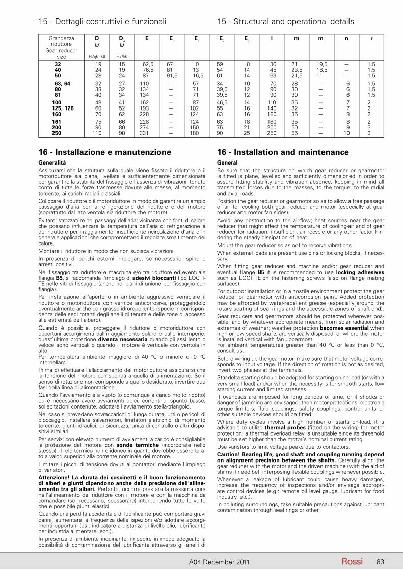
83A04 December 2011
15 - Dettagli costruttivi e funzionali 15 - Structural and operational details
Grandezza D D3 E E0 E1 E2 E3 l m m0 n r riduttore Ø Ø Gear reducer size H7/j6, k6 H7/h6
32 19 15 62,5 67 0 59 8 36 21 19,5 – 1,5 40 24 19 76,5 81 13 54 14 45 23,5 18,5 – 1,5 50 28 24 87 91,5 16,5 61 14 63 21,5 11,0 – 1,5 63, 64 32 27 110 – 57 34 10 70 28 – 6 1,5 80 38 32 134 – 71 39,5 12 90 30 – 6 1,5 81 40 34 134 – 71 39,5 12 90 30 – 6 1,5 100 48 41 162 – 87 46,5 14 110 35 – 7 2 125, 126 60 52 193 – 102 55 16 140 32 – 7 2 160 70 62 228 – 124 63 16 180 35 – 8 2 161 75 66 228 – 124 63 18 180 35 – 8 2 200 90 80 274 – 150 75 21 200 50 – 9 3 250 110 98 331 – 180 90 25 250 55 – 10 3
16 - Installazione e manutenzioneGeneralitàAssicurarsi che la struttura sulla quale viene fissato il riduttore o il mo toriduttore sia piana, livellata e sufficientemente dimensionata per garantire la stabilità del fissaggio e l’assenza di vibrazioni, tenuto conto di tutte le forze trasmesse dovute alle masse, al momento torcente, ai carichi radiali e assiali.Collocare il riduttore o il motoriduttore in modo da garantire un am pio passaggio d’aria per la refrigerazione del riduttore e del motore (soprattutto dal lato ventola sia riduttore che motore).Evitare: strozzature nei passaggi dell’aria; vicinanza con fonti di ca lore che possano influenzare la temperatura dell’aria di refrigerazione e del riduttore per irraggiamento; insufficiente ricircolazione d’aria e in generale applicazioni che compromettano il regolare smaltimento del calore.Montare il riduttore in modo che non subisca vibrazioni.In presenza di carichi esterni impiegare, se necessario, spine o ar resti positivi.Nel fissaggio tra riduttore e macchina e/o tra riduttore ed eventuale flangia B5, si raccomanda l’impiego di adesivi bloccanti tipo LOCTI-TE nelle viti di fissaggio (anche nei piani di unione per fissaggio con flangia).Per installazione all’aperto o in ambiente aggressivo verniciare il ri duttore o motoriduttore con vernice anticorrosiva, proteggendolo eventualmente an che con grasso idrorepellente (specie in corrispon-denza delle sedi rotanti degli anelli di tenuta e delle zone di accesso alle estremità dell’albero).Quando è possibile, proteggere il riduttore o motoriduttore con opportuni accorgimenti dall’irraggiamento solare e dalle intemperie: quest’ultima protezione diventa necessaria quando gli assi lento o veloce sono verticali o quando il motore è verticale con ventola in alto.Per temperatura ambiente maggiore di 40 °C o minore di 0 °C in terpellarci.Prima di effettuare l’allacciamento del motoriduttore assicurarsi che la tensione del motore corrisponda a quella di alimentazione. Se il senso di rotazione non corrisponde a quello desiderato, invertire due fasi della linea di alimentazione.Quando l’avviamento è a vuoto (o comunque a carico molto ridotto) ed è necessario avere avviamenti dolci, correnti di spunto basse, sollecitazioni contenute, adottare l’avviamento stella-triangolo.Nel caso si prevedano sovraccarichi di lunga durata, urti o pericoli di bloccaggio, installare salvamotori, limitatori elettronici di momento torcente, giunti idraulici, di sicurezza, unità di controllo o altri dispo-sitivi similari.Per servizi con elevato numero di avviamenti a carico è consigliabile la protezione del motore con sonde termiche (incorporate nello stesso): il relé termico non è idoneo in quanto dovrebbe essere tara-to a valori superiori alla corrente nominale del motore.Limitare i picchi di tensione dovuti ai contattori mediante l’impiego di varistori.Attenzione! La durata dei cuscinetti e il buon funzionamento di alberi e giunti dipendono anche dalla precisione dell’alline-amento tra gli alberi. Pertanto, occorre prestare la massima cura nell’allineamento del riduttore con il motore e con la macchina da comandare (se necessario, spessorare) interponendo tutte le volte che è possibile giunti elastici.Quando una perdita accidentale di lubrificante può comportare gra vi danni, aumentare la frequenza delle ispezioni e/o adottare accorgi-menti opportuni (es.: indicatore a distanza di livello olio, lubrifican te per industria alimentare, ecc.).In presenza di ambiente inquinante, impedire in modo adeguato la possibilità di contaminazione del lubrificante attraverso gli anelli di
16 - Installation and maintenanceGeneralBe sure that the structure on which gear reducer or gearmotor is fitted is plane, le velled and sufficiently dimensioned in order to assure fitting stability and vibration absence, keeping in mind all transmitted forces due to the masses, to the torque, to the radial and axial loads.Position the gear reducer or gearmotor so as to allow a free passage of air for cooling both gear reducer and motor (especially at gear reducer and motor fan sides).Avoid: any obstruction to the air-flow; heat sources near the gear reducer that might affect the temperature of cooling-air and of gear reducer for radiation; insufficient air recycle or any other factor hin-dering the steady dissipation of heat.Mount the gear reducer so as not to receive vibrations.When external loads are present use pins or locking blocks, if ne ces-sary.When fitting gear reducer and machine and/or gear reducer and eventual flange B5 it is recommended to use locking adhesives such as LOCTITE on the fastening screws (also on flange mating surfaces).For outdoor installation or in a hostile environment protect the gear reducer or gearmotor with anticorrosion paint. Added protection may be afforded by water-repellent grease (especially around the rotary seating of seal rings and the accessible zones of shaft end).Gear reducers and gearmotors should be protected wherever pos-sible, and by whatever appropriate means, from solar radiation and extremes of weather; weather protection becomes essential when high or low speed shafts are vertically disposed, or where the motor is installed vertical with fan uppermost.For ambient temperatures greater than 40 °C or less than 0 °C, consult us.Before wiring-up the gearmotor, make sure that motor voltage corre-sponds to input voltage. If the direction of rotation is not as desired, invert two phases at the terminals.Star-delta starting should be adopted for starting on no load (or with a very small load) and/or when the necessity is for smooth starts, low starting current and limited stresses.If overloads are imposed for long periods of time, or if shocks or danger of jamming are envisaged, then motor-protections, electronic torque limiters, fluid couplings, safety couplings, control units or other suitable devices should be fitted.Where duty cycles involve a high number of starts on-load, it is advisable to utilize thermal probes (fitted on the wiring) for motor protection; a thermal overload relay is unsuitable since its threshold must be set higher than the motor’s nominal current rating.Use varistors to limit voltage peaks due to contactors.Caution! Bearing life, good shaft and coupling running depend on alignment precision between the shafts. Carefully align the gear reducer with the motor and the driven machine (with the aid of shims if need be), interposing flexible couplings whenever possible.Whenever a leakage of lubricant could cause heavy damages, in crease the frequency of inspections and/or envisage appropri-ate control devices (e.g.: remote oil level gauge, lubricant for food industry, etc.).In polluting surroundings, take suitable precautions against lubricant contamination through seal rings or other.
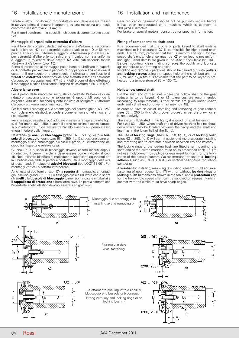
84 A04 December 2011
16 - Installazione e manutenzione 16 - Installation and maintenance
tenuta o altro.Il riduttore o motoriduttore non deve essere messo in servizio prima di essere incorporato su una macchina che risulti conforme alla di rettiva 2006/42/CE.Per motori autofrenanti o speciali, richiedere documentazione speci-fica.
Montaggio di organi sulle estremità d’alberoPer il foro degli organi calettati sull’estremità d’albero, si raccoman-da la tolleranza H7; per estremità d’albero veloce con D � 55 mm, purché il carico sia uniforme e leggero, la tolleranza può essere G7; per estremità d’albero lento, salvo che il carico non sia uniforme e leggero, la tolleranza deve essere K7. Altri dati secondo tabella «Estremità d’albero» (cap. 15).Prima di procedere al montaggio pulire bene e lubrificare le superfi-ci di contatto per evitare il pericolo di grippaggio e l’ossidazione di contatto. Il montaggio e lo smontaggio si effettuano con l’ausilio di tiranti ed estrattori servendosi del foro filettato in testa all’estremità d’albero; per accoppiamenti H7/m6 e K7/j6 è consigliabile effettuare il montaggio a caldo riscaldando l’organo da calettare a 80 � 100 °C.
Albero lento cavoPer il perno delle macchine sul quale va calettato l’albero cavo del riduttore, raccomandiamo le tolleranze j6 oppure k6 secondo le esigenze. Altri dati se condo quanto indicato al paragrafo «Estremità d’albero» e «Perno macchina» (cap. 15).Per facilitare il montaggio e lo smontaggio dei riduttori grand. 63 ...250 (con gola anello elastico), proce dere come raffigurato nelle figg. a, b rispettivamente.Per il fissaggio assiale si può adottare il sistema raffigurato nelle figg. c, d. Per grand. 63 ... 250, quando il perno macchina è senza battuta, si può interporre un distanziale tra l’anello elastico e il perno stesso (metà inferiore della figura d).Utilizzando gli anelli di bloccaggio (grand. 32 ... 50, fig. e), o la bus-sola di bloccaggio (grandezze 63 ... 250, fig. f) si possono avere un montaggio e uno smontaggio più facili e precisi e l’eliminazione del gioco tra linguetta e relativa cava.Gli anelli o la bussola di bloccaggio devono essere inseriti dopo il montaggio, il perno macchina deve essere come indicato al cap. 15. Non utilizzare bisolfuro di molibdeno o lubrificanti equivalenti per la lubrificazione delle superfici a contatto. Per il montaggio della vite si raccomanda l’impiego di adesivi bloccanti tipo LOCTITE 601. Per montaggi verticali a soffitto interpellarci.A richiesta si può fornire (cap. 17) la rosetta di montaggio, smontag-gio (escluso grand. 32 ... 50) e fissaggio assiale riduttore con o senza gli anelli o la bussola di bloccaggio (dimensioni indicate in tabella) e il cappellotto di protezione albero lento cavo. Le parti a contatto con l’eventuale anello elastico devono essere a spigolo vivo.
Gear reducer or gearmotor should not be put into service before it has been incorporated on a machine which is conform to 2006/42/EC directive.For brake or special motors, consult us for specific information.
Fitting of components to shaft endsIt is recommended that the bore of parts keyed to shaft ends is ma chined to H7 tolerance; G7 is permissible for high speed shaft ends D � 55 mm, provided that load is uniform and light; for low speed shaft ends, tolerance must be K7 when load is not uniform and light. Other details are given in the «Shaft end» table (ch. 15).Before mounting, clean mating surfaces thoroughly and lubricate against seizure and fretting corrosion.Installing and removal operations should be carried out with pullers and jacking screws using the tapped hole at the shaft butt-end; for H7/m6 and K7/j6 fits it is advisable that the part to be keyed is pre-heated to a temperature of 80 � 100 °C.
Hollow low speed shaftFor the shaft end of machines where the hollow shaft of the gear reducer is to be keyed, j6 or k6 tolerances are recommended (according to requirements). Other details are given under «Shaft end» and «Shaft end of driven machine» (ch. 15).In order to have an easier installing and removing of gear reducer sizes 63 ... 250 (with circlip groove) proceed as per the drawings a, b, respectively.The system illustrated in the fig. c, d is good for axial fastening.For sizes 63 ... 250, when shaft end of driven machine has no shoul-der a spacer may be located between the circlip and the shaft end itself (as in the lower half of the fig. d).The use of locking rings (sizes 32 ...50, fig. e), or of locking bush (sizes 63 ... 250, fig. f) will permit easier and more accurate installing and removing and to eliminate backlash between key and keyway.The locking rings or the locking bush are fitted after mounting, the shaft end of the driven machine must be as prescribed at ch. 15. Do not use molybdenum bisulphide or equivalent lubricant for the lubri-cation of the parts in contact. We recommend the use of a locking adhesive such as LOCTITE 601. For vertical ceiling-type mounting, contact us.A washer for installing, removing (excluding sizes 32 ... 50) and axial fastening of gear reducer (ch. 17) with or without locking rings or locking bush (dimensions shown in the table) and a protection cap for the hollow low speed shaft can be supplied on request. Parts in contact with the circlip must have sharp edges.
Montaggio a) e smontaggio b)Installing a) and removing b)
Fissaggio assialeAxial fastening
Calettamento con linguetta e anelli dibloccaggio e) o bussola di bloccaggio f)Fitting with key and locking rings e) or
locking bush f)
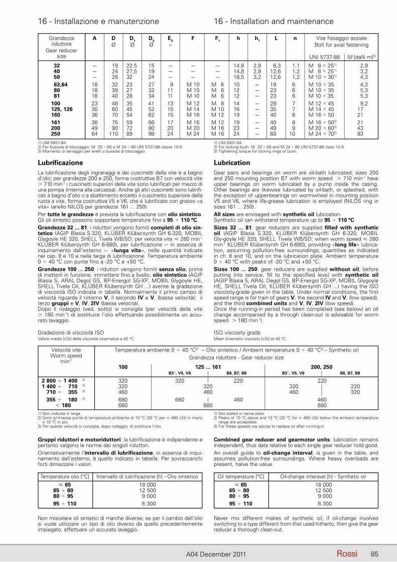
85A04 December 2011
16 - Installazione e manutenzione 16 - Installation and maintenance
LubrificazioneLa lubrificazione degli ingranaggi e dei cuscinetti della vite è a bagno d’olio; per grandezze 200 e 250, forma costruttiva B7 con velocità vite � 710 min-1 i cuscinetti superiori della vite sono lubrificati per mezzo di una pompa (interna alla carcassa). Anche gli altri cuscinetti sono lubrifi-cati a bagno d’olio o a sbattimento eccetto il cuscinetto superiore della ruota a vite, forma costruttiva V5 e V6, che è lubrificato con grasso «a vita» (anello NILOS per grandezze 161 ... 250).Per tutte le grandezze è prevista la lubrificazione con olio sintetico. Gli oli sintetici possono sopportare temperature fino a 95 � 110 °C.Grandezze 32 ... 81: i riduttori vengono forniti completi di olio sin-tetico (AGIP Blasia S 320, KLÜBER Klübersynth GH 6-320, MOBIL Glygoyle HE 320, SHELL Tivela WB/SD; per velocità vite � 280 min-1 KLÜBER Klübersynth GH 6-680), per lubrificazione – in assenza di inquinamento dall’esterno – «lunga vita», nelle quantità indicate nei cap. 8 e 10 e nella targa di lubrificazione. Temperatura ambiente 0 � 40 °C con punte fino a -20 °C e +50 °C.Grandezze 100 ... 250: i riduttori vengono forniti senza olio; prima di metterli in funzione, immettere fino a livello, olio sintetico (AGIP Blasia S, ARAL Degol GS, BP-Energol SG-XP, MOBIL Glygoyle HE, SHELL Tivela Oil, KLÜBER Klübersynth GH ...) avente la gradazione di viscosità ISO indicata in tabella. Normalmente il primo campo di velocità riguarda il rotismo V, il secondo IV e V, (bassa velocità); il terzo gruppi e V, IV, 2IV (bassa velocità).Dopo il rodaggio (ved. sotto) si consiglia (per velocità della vite� 180 min-1) di sostituire l’olio effettuando possibilmente un accu-rato lavaggio.
LubricationGear pairs and bearings on worm are oil-bath lubricated; sizes 200 and 250 mounting position B7 with worm speed � 710 min-1 have upper bearings on worm lubricated by a pump inside the casing. Other bearings are likewise lubricated by oil-bath, or splashed, with the exception of upper-bearings on wormwheel in mounting position V5 and V6, where life-grease lubrication is employed (NILOS ring in sizes 161 ... 250).All sizes are envisaged with synthetic oil lubrication.Synthetic oil can withstand temperature up to 95 � 110 °C.Sizes 32 ... 81: gear reducers are supplied filled with synthetic oil (AGIP Blasia S 320, KLÜBER Klübersynth GH 6-320, MOBIL Gly-goyle HE 320, SHELL Tivela WB/SD; when worm speed � 280 min-1 KLÜBER Klübersynth GH 6-680), providing «long life» lubrica-tion, assuming pollution-free surroundings; quantities as indicatedin ch. 8 and 10, and on the lubrication plate. Ambient temperature0 � 40 °C with peaks of -20 °C and +50 °C.Sizes 100 ... 250: gear reducers are supplied without oil; before putting into service, fill to the specified level with synthetic oil(AGIP Blasia S, ARAL Degol GS, BP-Energol SG-XP, MOBIL Glygoyle HE, SHELL Tivela Oil, KLÜBER Klübersynth GH ...) having the ISO viscosity-grade given in the table. Under normal conditions, the first speed range is for train of gears V, the second IV and V, (low speed), and the third combined units and V, IV, 2IV (low speed).Once the running-in period has been completed (see below) an oil change accompanied by a through clean-out is advisable for worm speed � 180 min-1).
1) UNI 5931-84.2) Per bussola di bloccaggio: M 20 � 65 e M 24 � 80 UNI 5737-88 classe 10.9.3) Momento di serraggio per anelli o bussola di bloccaggio.
1) UNI 5931-84.2) For locking bush: M 20 � 65 and M 24 � 80 UNI 5737-88 class 10.9.3) Tightening torque for locking rings or bush.
Grandezza A D D1 D3 E3 F F1 h h1 L n Vite fissaggio assiale riduttore Ø Ø Ø ≈ Bolt for axial fastening Gear reducer size UNI 5737-88 M [daN m]3)
32 – 19 22,5 15 – – – 14,8 2,8 6,3 1,1 M 8 � 251) 2,9 40 – 24 27,5 19 – – – 14,8 2,8 12,6 1,2 M 8 � 251) 3,2 50 – 28 32 24 – – – 18,5 3,2 12,6 1,2 M 10 � 301) 4,3 63,64 18 32 23 27 9 M 10 M 6 10 – 19 6 M 10 � 35 4,3 80 18 38 27 32 11 M 10 M 6 12 – 23 6 M 10 � 35 5,3 81 18 40 28 34 11 M 10 M 6 12 – 23 6 M 10 � 35 5,3 100 23 48 35 41 13 M 12 M 8 14 – 28 7 M 12 � 45 9,2 125, 126 30 60 45 52 15 M 14 M 10 16 – 35 7 M 14 � 45 17 160 36 70 54 62 15 M 16 M 12 19 – 40 8 M 16 � 50 21 161 36 75 59 66 17 M 16 M 12 19 – 40 8 M 16 � 503) 21 200 49 90 72 80 20 M 20 M 16 23 – 49 9 M 20 � 602) 43 250 64 110 89 98 24 M 24 M 16 24 – 60 10 M 24 � 702) 83
Gradazione di viscosità ISOValore medio [cSt] della viscosità cinematica a 40 °C.
Velocità vite Temperatura ambiente 0 � 40 °C2) – Olio sintetico / Ambient temperature 0 � 40 °C2) – Synthetic oil Worm speed Grandezza riduttore - Gear reducer size min-1
100 125 ... 161 200, 250 B31), V5, V6 B6, B7, B8 B31), V5, V6 B6, B7, B8
2 800 � 1 400 3) 320 320 220 220 1 400 � 1 710 3) 320 320 320 220 2 710 � 1 355 3) 460 460 460 320 355 � 1 180 3) 680 680 460 460 � 180 680 680 6801) Non indicata in targa.2) Sono ammesse punte di temperatura ambiente di 10 °C (20 °C per � 460 cSt) in meno
o 10 °C in più.3) Per queste velocità si consiglia, dopo rodaggio, di sostituire l’olio.
ISO viscosity gradeMean kinematic viscosity [cSt] at 40 °C.
1) Not stated in name plate.2) Peaks of 10 °C above and 10 °C (20 °C for � 460 cSt) below the ambient temperature
range are acceptable.3) For these speeds we advise to replace oil after running-in.
Temperatura olio [°C] Intervallo di lubrificazione [h] - Olio sintetico
� 65 18 000 65 � 800 12 500 80 � 950 9 000 95 � 110 6 300
Oil temperature [°C] Oil-change interaval [h] - Synthetic oil
� 65 18 000 65 � 800 12 500 80 � 950 9 000 95 � 110 6 300
Gruppi riduttori e motoriduttori: la lubrificazione è indipendente e pertanto valgono le norme dei singoli riduttori.Orientativamente l’intervallo di lubrificazione, in assenza di inqui-namento dall’esterno, è quello indicato in tabella. Per sovraccarichi forti dimezzare i valori.
Combined gear reducer and gearmotor units: lubrication remains independent, thus data relative to each single gear reducer hold good.An overall guide to oil-change interval, is given in the table, and assumes pollution-free surroundings. Where heavy overloads are present, halve the value.
Non miscelare oli sintetici di marche diverse; se per il cambio dell’olio si vuole utilizzare un tipo di olio diverso da quello precedentemente impiegato, effettuare un accurato lavaggio.
Never mix different makes of synthetic oil; if oil-change involvesswitching to a type different from that used hitherto, then give the gear reducer a thorough clean-out.
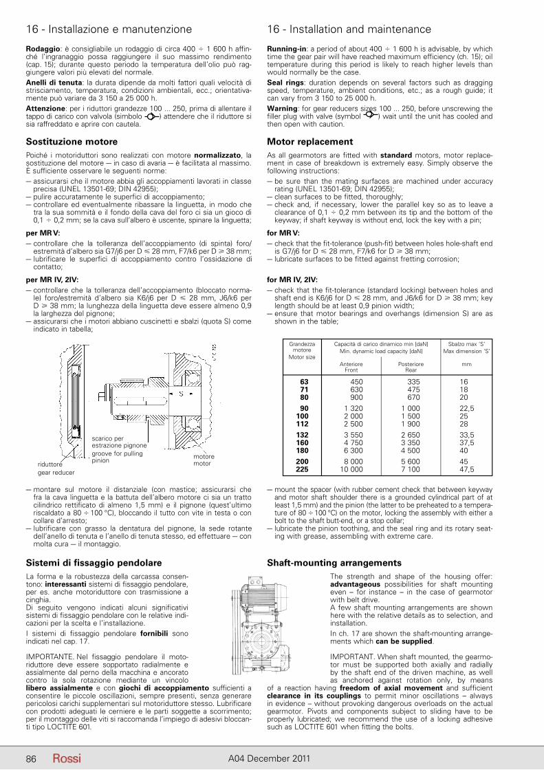
86 A04 December 2011
16 - Installazione e manutenzione 16 - Installation and maintenance
Rodaggio: è consigliabile un rodaggio di circa 400 � 1 600 h affin-ché l’ingranaggio possa raggiungere il suo massimo rendimento (cap. 15); durante questo periodo la temperatura dell’olio può rag-giungere valori più elevati del normale.Anelli di tenuta: la durata dipende da molti fattori quali velocità di strisciamento, temperatura, condizioni ambientali, ecc.; orientativa-mente può variare da 3 150 a 25 000 h.Attenzione: per i riduttori grandezze 100 ... 250, prima di allentare il tappo di carico con valvola (simbolo ) attendere che il riduttore si sia raffreddato e aprire con cautela.
Sostituzione motorePoiché i motoriduttori sono realizzati con motore normalizzato, la sostituzione del motore – in caso di avaria – è facilitata al massimo. È sufficiente osservare le seguenti norme:– assicurarsi che il motore abbia gli accoppiamenti lavorati in classe
precisa (UNEL 13501-69; DIN 42955);– pulire accuratamente le superfici di accoppiamento;– controllare ed eventualmente ribassare la linguetta, in modo che
tra la sua sommità e il fondo della cava del foro ci sia un gioco di 0,1 � 0,2 mm; se la cava sull’albero è uscente, spinare la linguetta;
per MR V:– controllare che la tolleranza dell’accoppiamento (di spinta) foro/
estremità d’albero sia G7/j6 per D � 28 mm, F7/k6 per D � 38 mm;– lubrificare le superfici di accoppiamento contro l’ossidazione di
contatto;
per MR IV, 2IV:– controllare che la tolleranza dell’accoppiamento (bloccato norma-
le) foro/estremità d’albero sia K6/j6 per D � 28 mm, J6/k6 perD � 38 mm; la lunghezza della linguetta deve essere almeno 0,9 la larghezza del pignone;
– assicurarsi che i motori abbiano cuscinetti e sbalzi (quota S) come indicato in tabella;
Running-in: a period of about 400 � 1 600 h is advisable, by which time the gear pair will have reached maximum efficiency (ch. 15); oil temperature during this period is likely to reach higher levels than would normally be the case.Seal rings: duration depends on several factors such as dragging speed, temperature, ambient conditions, etc.; as a rough guide; it can vary from 3 150 to 25 000 h.Warning: for gear reducers sizes 100 ... 250, before unscrewing the filler plug with valve (symbol ) wait until the unit has cooled and then open with caution.
Motor replacementAs all gearmotors are fitted with standard motors, motor replace-ment in case of breakdown is extremely easy. Simply observe the following instructions:– be sure than the mating surfaces are machined under accuracy
rating (UNEL 13501-69; DIN 42955);– clean surfaces to be fitted, thoroughly;– check and, if necessary, lower the parallel key so as to leave a
clearance of 0,1 � 0,2 mm between its tip and the bottom of the keyway; if shaft keyway is without end, lock the key with a pin;
for MR V:– check that the fit-tolerance (push-fit) between holes hole-shaft end
is G7/j6 for D � 28 mm, F7/k6 for D � 38 mm;– lubricate surfaces to be fitted against fretting corrosion;
for MR IV, 2IV:– check that the fit-tolerance (standard locking) between holes and
shaft end is K6/j6 for D � 28 mm, and J6/k6 for D � 38 mm; key length should be at least 0,9 pinion width;
– ensure that motor bearings and overhangs (dimension S) are as shown in the table;
– montare sul motore il distanziale (con mastice; assicurarsi che fra la cava linguetta e la battuta dell’albero motore ci sia un tratto ci lindrico rettificato di almeno 1,5 mm) e il pignone (quest’ultimo riscaldato a 80 � 100 °C), bloccando il tutto con vite in testa o con collare d’arresto;
– lubrificare con grasso la dentatura del pignone, la sede rotante dell’anello di tenuta e l’anello di tenuta stesso, ed effettuare – con molta cura – il montaggio.
– mount the spacer (with rubber cement check that between keyway and motor shaft shoulder there is a grounded cylindrical part of at least 1,5 mm) and the pinion (the latter to be preheated to a tempera-ture of 80 � 100 °C) on the motor, locking the assembly with either a bolt to the shaft butt-end, or a stop collar;
– lubricate the pinion toothing, and the seal ring and its rotary seat-ing with grease, assembling with extreme care.
Sistemi di fissaggio pendolareLa forma e la robustezza della car cassa consen-tono: interessanti si stemi di fissaggio pendolare, per es. anche motoriduttore con trasmissione a cinghia.Di seguito vengono indicati alcuni significativi sistemi di fissaggio pendolare con le relative indi-cazioni per la scelta e l’installazione.I sistemi di fissaggio pendolare fornibili sono in dicati nel cap. 17.
IMPORTANTE. Nel fissaggio pendolare il moto-riduttore deve essere sopportato radialmente e as sialmente dal perno della macchina e ancorato contro la sola rotazione mediante un vincolo libero assialmente e con giochi di accoppiamento sufficienti a consentire le piccole oscillazioni, sempre presenti, senza generare pericolosi carichi supplementari sul motoriduttore stesso. Lubrificare con prodotti adeguati le cerniere e le parti soggette a scorrimento; per il montaggio delle viti si raccomanda l’impiego di adesivi bloccan-ti tipo LOCTITE 601.
Shaft-mounting arrangementsThe strength and shape of the housing offer: advantageous possibilities for shaft mounting even – for instance – in the case of gearmotor with belt drive.A few shaft mounting arrangements are shown here with the relative details as to selection, and installation.In ch. 17 are shown the shaft-mounting arrange-ments which can be supplied.
IMPORTANT. When shaft mounted, the gearmo-tor must be supported both axially and radially by the shaft end of the driven machine, as well as anchored against rotation only, by means
of a reaction having freedom of axial movement and sufficient clearance in its couplings to permit minor oscillations – always in evidence – without provoking dangerous overloads on the actual gearmotor. Pivots and components subject to sliding have to be properly lubricated; we recommend the use of a locking adhesive such as LOCTITE 601 when fitting the bolts.
Grandezza Capacità di carico dinamico min [daN] Sbalzo max ‘S’ motore Min. dynamic load capacity [daN] Max dimension ‘S’ Motor size Anteriore Posteriore mm Front Rear
63 450 335 16 71 630 475 18 80 900 670 20 90 1 320 1 000 22,5 100 2 000 1 500 25 112 2 500 1 900 28 132 3 550 2 650 33,5 160 4 750 3 350 37,5 180 6 300 4 500 40 200 8 000 5 600 45 225 10 000 7 100 47,5
motoremotor
scarico perestrazione pignonegroove for pullingpinionriduttore
gear reducer
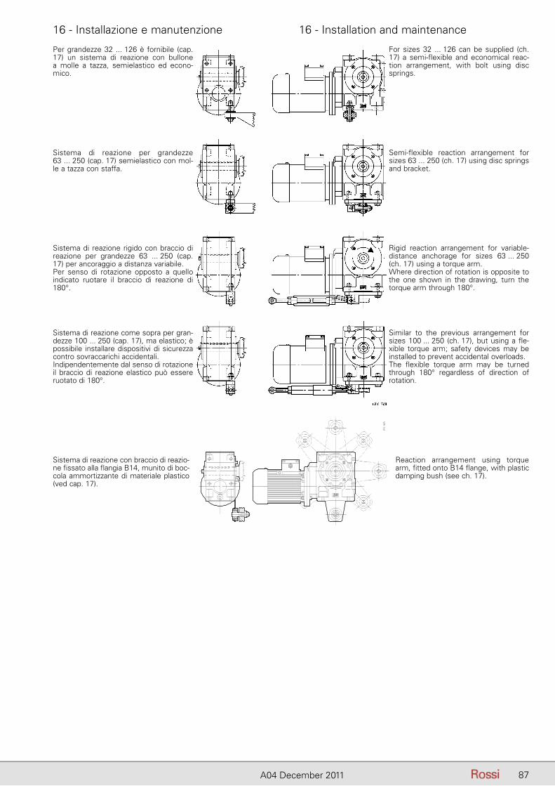
87A04 December 2011
16 - Installazione e manutenzione 16 - Installation and maintenance
Per grandezze 32 ... 126 è fornibile (cap. 17) un sistema di reazione con bullone a molle a tazza, semielastico ed econo-mico.
Sistema di reazione per grandezze63 ... 250 (cap. 17) semielastico con mol-le a tazza con staffa.
Sistema di reazione rigido con braccio di reazione per grandezze 63 ... 250 (cap. 17) per ancoraggio a distanza variabile.Per senso di rotazione opposto a quello indicato ruotare il braccio di reazione di 180°.
Sistema di reazione come sopra per gran-dezze 100 ... 250 (cap. 17), ma elastico; è possibile installare dispositivi di sicurezza contro sovraccarichi accidentali.Indipendentemente dal senso di rotazione il braccio di reazione elastico può es sere ruotato di 180°.
Similar to the previous arrangement for sizes 100 ... 250 (ch. 17), but using a fle-xible torque arm; safety devices may be installed to prevent accidental overloads.The flexible torque arm may be turned through 180° regardless of direction of rotation.
Rigid reaction arrangement for variable-distance anchorage for sizes 63 ... 250 (ch. 17) using a torque arm.Where direction of rotation is opposite to the one shown in the drawing, turn the torque arm through 180°.
Semi-flexible reaction arrangement for sizes 63 ... 250 (ch. 17) using disc springs and bracket.
For sizes 32 ... 126 can be supplied (ch. 17) a semi-flexible and economical reac-tion arrangement, with bolt using disc springs.
Sistema di reazione con braccio di reazio-ne fissato alla flangia B14, munito di boc-cola ammortizzante di materiale plastico (ved cap. 17).
Reaction arrangement using torque arm, fitted onto B14 flange, with plastic damping bush (see ch. 17).
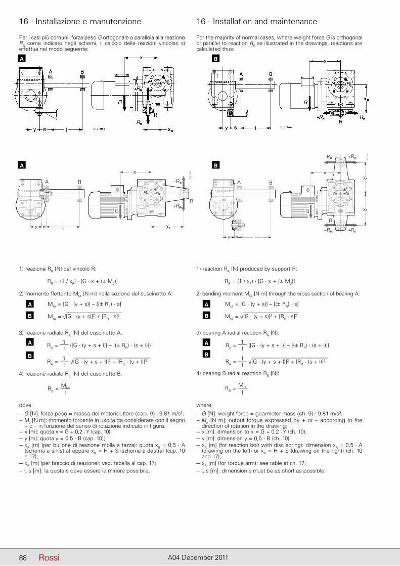
88 A04 December 2011
16 - Installazione e manutenzione 16 - Installation and maintenance
Per i casi più comuni, forza peso G ortogonale o parallela alla reazione RR come indicato negli schemi, il calcolo delle reazioni vincolari si effettua nel modo seguente:
For the majority of normal cases, where weight force G is orthogonal or parallel to reaction RR as illustrated in the drawings, reactions are calculated thus:
BA
2) momento flettente MfA [N m] nella sezione del cuscinetto A:
MfA = [G · (y + s)] – [(± RR) · s]
MfA = √[G · (y + s)]2 + [RR · s]2
2) bending moment MfA [N m] through the cross-section of bearing A:
MfA = [G · (y + s)] – [(± RR) · s]
MfA = √[G · (y + s)]2 + [RR · s]2
3) reazione radiale RA [N] del cuscinetto A:
RA = 1l
{[G · (y + s + l)] – [(± RR) · (s + l)]}
RA = 1l
√[G · (y + s + l)]2 + [RR · (s + l)]2
3) bearing A radial reaction RA [N]:
RA = 1l
{[G · (y + s + l)] – [(± RR) · (s + l)]}
RA = 1l
√[G · (y + s + l)]2 + [RR · (s + l)]2
4) reazione radiale RB [N] del cuscinetto B:
RB = MfA
l
4) bearing B radial reaction RB [N]:
RB = MfA
l
dove:
− G [N]: forza peso = massa del motoriduttore (cap. 9) · 9,81 m/s2;− M2 [N m]: momento torcente in uscita da considerare con il segno
+ o – in funzione del senso di rotazione indicato in figura;– x [m]: quota x = G + 0,2 · Y (cap. 10);– y [m]: quota y = 0,5 · B (cap. 10);– xR [m] (per bullone di reazione molla a tazza): quota xR = 0,5 · A
(schema a sinistra) oppure xR = H + S (schema a destra) (cap. 10 e 17);
– xR [m] (per braccio di reazione): ved. tabella al cap. 17;− l, s [m]: la quota s deve essere la minore possibile.
where:
− G [N]: weight force = gearmotor mass (ch. 9) · 9,81 m/s2;− M2 [N m]: output torque expressed by + or – according to the
direction of rotation in the drawing;– x [m]: dimension to x = G + 0,2 · Y (ch. 10);– y [m]: dimension y = 0,5 · B (ch. 10);– xR [m] (for reaction bolt with disc spring): dimension xR = 0,5 · A
(drawing on the left) or xR = H + S (drawing on the right) (ch. 10 and 17);
– xR [m] (for torque arm): see table at ch. 17;− l, s [m]: dimension s must be as short as possible.
1) reazione RR [N] del vincolo R: 1) reaction RR [N] produced by support R:
RR = (1 / xR) · [G · x + (± M2)] RR = (1 / xR) · [G · x + (± M2)]
A
B
A
B
A
B
A
B
BA
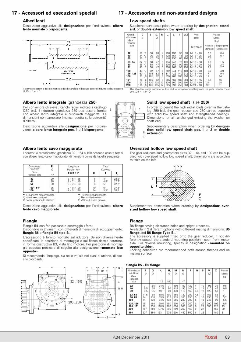
89A04 December 2011
17 - Accessori ed esecuzioni speciali 17 - Accessories and non-standard designs
Alberi lentiDescrizione aggiuntiva alla designazione per l’ordinazione: albero lento normale o bisporgente.
Low speed shaftsSupplementary description when ordering by designation: stand-ard, or double extension low speed shaft.
Grand. D E D1 h L1 L2 l 2 Z Vite Massa riduttore Ø Ø Bolt Mass Gear [kg] reducer size Normale Bisporgente
UNI 5737-88 Standard Double ext.
32 19 h7 30 28 4 108 138 36 78 M 6 � 20 0,3 0,4 40 24 h7 36 35 5 128 164 45 92 M 8 � 25 0,6 0,7 50 28 h7 42 35 5 148 190 63 106 M 8 � 25 0,8 1 63, 64 32 h7 58 47 5 184 242 70 126 M 10 � 30 1,2 1,5 80 38 h7 58 47 5 208 266 90 150 M 10 � 30 1,9 2,4 81 40 h7 58 47 5 208 266 90 150 M 10 � 30 2,1 2,7 100 48 h7 82 57 6 262 344 110 180 M 12 � 40 3,7 4,9 125, 126 60 h7 105 82 8 317 422 140 212 M 16 � 45 7 9,4 160 70 j6 105 82 8 355 460 180 250 M 16 � 45 11 14 161 75 j6 105 82 8 355 460 180 250 M 16 � 45 12,6 16 200 90 j6 130 102 10 430 560 200 300 M 20 � 60 21 28 250 110 j6 165 135 12 525 690 250 360 M 24 � 60 39 51
Albero lento integrale (grandezza 250)Per consentire gli elevati carichi radiali indicati a catalogo (250 bis), il riduttore grandezza 250 può essere fornito con albero lento integrale e cuscinetti maggiorati. Le dimensioni non cambiano (manca rosetta sulla estremità d’albero).
Descrizione aggiuntiva alla designazione per l’ordina-zione: albero lento integrale pos. 1 o 2 bisporgente.
Albero lento cavo maggioratoI riduttori e motoriduttori grandezze 32 ... 64 e 100 possono essere forniti con albero lento cavo maggiorato; dimensioni come da tabella seguente.
Solid low speed shaft (size 250)In order to permit the high radial loads given in the cata-log (250 bis), the gear reducer size 250 can be supplied with solid low speed shaft and strengthened bearings. Dimensions remain unchanged (missing the washer on shaft end).
Supplementary description when ordering by designa-tion: solid low speed shaft pos. 1 or 2 or double extension.
Oversized hollow low speed shaftThe gear reducers and gearmotors sizes 32 ... 64 and 100 can be sup-plied with oversized hollow low speed shaft; dimensions are according to table on the left.
Descrizione aggiuntiva alla designazione per l’ordinazione: albero lento cavo maggiorato.
Supplementary description when ordering by designation: over-sized hollow low speed shaft.
FlangiaFlangia B5 con fori passanti e centraggio «foro»Disponibile in 2 varianti con differenti dimensioni di accoppiamento: flangia B5 e flangia B5 tipo B...L’accessorio è fornito montato sul riduttore. Se non diversamente specificato, la posizione di montaggio è sul fianco destro riduttore, in forma costruttiva B3, vista lato motore. Per posizione di montag-gio opposta precisare di seguito alla designazione «montata lato opposto»Si raccomanda l’impiego, sia nelle viti sia nei piani di unione, di ade-sivi bloccanti.
FlangeB5 flange having clearance holes and spigot «recess».Available in 2 different options with different mating dimensions: B5 flange and B5 flange Type B...The accessory is supplied fitted onto the gear reducer. If not dif-ferently stated, the standard mounting position - seen from motor side. For reverse mounting, specify in designation «mounted on opposite side».Locking adhesives are recommended both around threads and on mating surface.
The shoulder outer diameter of the part, or of spacer abutting with the gear reducer must be (1,25 � 1,4) · D.
Il diametro esterno dell’elemento o del distanziale in battuta contro il riduttore deve essere (1,25 � 1,4) · D.
Grandezza D Linguetta Cava riduttore Ø Parallel key Keyway Gear b x h x l* b t t1 reducer size H7
32 20 6 � 6 � 36 6 41) 22,21)
40 25 8 � 7 � 45 8 4,51) 27,71)
50 30 8 � 7 � 63 8 51) 32,21)
632), 642) 35 10 � 8 � 90 10 61) 37,31)
100 50 14 � 9 � 110 14 5,51) 53,81)
* Lunghezza raccomandata.1) Valori non unificati.2) Senza gola anello elastico.
* Recommended length.1) Not unified values.2) Without circlip groove.
flangia B5 - B5 flange
Grandezza F G H1 H2 M N P Q S V Z Massa riduttore Ø Ø Ø Ø Ø � Mass Gear kg reducer size h12 h12 H7
32 27 55 34,5 71 100 80 120 4 10 95 39 0,5 40 29,5 68 41,5 80 115 95 140 4 11 110 46 0,8 50 29,5 85 49 80 130 110 160 4,5 12 125 53 1 63, 64 11,5 80 58,5 100 165 130 200 4,5 14 152 63 2 80, 81 14 110 69,5 112 215 180 250 5 16 196 75 3,2 100 14 130 84,5 132 265 230 300 5 18 248 90 5,5 125, 126 188 180 99,5 150 300 250 350 6 20 290 106 8,5 160, 161 188 230 118,5 180 350 300 400 6 22 350 125 13 200 188 250 137,5 200 400 350 450 6 22 – 150 20 250 228 350 163 236 500 450 550 6 25 – 180 31
(32...161)
(200...250)
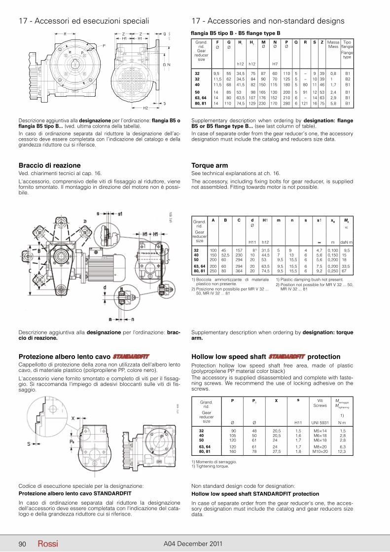
90 A04 December 2011
17 - Accessori ed esecuzioni speciali 17 - Accessories and non-standard designs
Descrizione aggiuntiva alla designazione per l’ordinazione: flangia B5 o flangia B5 tipo B... (ved. ultima colonna della tabella).In caso di ordinazione separata dal riduttore la designazione dell’ac-cessorio deve essere completata con l’indicazione del catalogo e della grandezza riduttore cui si riferisce.
Supplementary description when ordering by designation: flange B5 or B5 flange type B... (see last column of table).In case of separate order from the gear reducer’s one, the accessory designation must include the catalog and reducers size data.
flangia B5 tipo B - B5 flange type B
Grand.rid.
Gearreducer
size
FØ
GØ
H1 H2 MØ
NØ
PØ
Q R S Z MassaMass
Tipo fl angiaFlange type
h12 h12 H7
32 9,5 55 34,5 75 87 60 110 5 – 9 39 0,8 B132 11,5 62 34,5 84 90 70 125 5 – 10 39 1 B240 11,5 68 41,5 82 150 115 180 5 80 11 46 1,7 B1
50 14 85 53 98 165 130 200 5 91 12 53 2,4 B163, 64 14 80 63,5 107 176 152 210 6 – 14 63 2,9 B180, 81 14 110 74,5 129 230 170 280 6 121 16 75 5,8 B1
Braccio di reazioneVed. chiarimenti tecnici al cap. 16.
Torque armSee technical explanations at ch. 16.
Grand.rid.
Gearreducer
size
A B C d H1 m n s s1 xR M2Ø
�
H11 h12 ≈ m daN m
32 100 45 157 81) 31,5 5 9 4 4,7 0,100 9,540 150 52,5 230 10 44,5 7 13 6 5,6 0,150 1550 200 60 294 20 53 9,5 15,5 6 5,6 0,200 18
63, 64 200 60 294 20 63,5 9,5 15,5 6 7,5 0,200 33,580, 81 250 80 364 20 74,5 9,5 15,5 6 9,2 0,250 67
Descrizione aggiuntiva alla designazione per l’ordinazione: brac-cio di reazione.
Supplementary description when ordering by designation: torque arm.
1) Boccola ammortizzante di materiale plastico non presente.
2) Posizione non possibile per MR V 32 ... 50, MR IV 32 ... 81
1) Plastic damping bush not present.2) Position not possible for MR V 32 ... 50,
MR IV 32 ... 81
L'accessorio, comprensivo delle viti di fissaggio al riduttore, viene fornito smontato. Il montaggio in direzione del motore non è possi-bile.
The accessory, including fixing bolts for gear reducer, is supplied not assembled. Fitting towards motor is not possible.
Protezione albero lento cavo Cappellotto di protezione della zona non utilizzata dell'albero lento cavo, di materiale plastico (polipropilene PP, colore nero).
L'accessorio viene fornito smontato e completo di viti per il fissag-gio. Si raccomanda l'impiego di adesivi bloccanti sulle viti di fis-saggio.
Codice di esecuzione speciale per la designazione:Protezione albero lento cavo STANDARDFITIn caso di ordinazione separata dal riduttore la designazione dell'accessorio deve essere completata con l'indicazione del cata-logo e della grandezza riduttore cui si riferisce.
Hollow low speed shaft protection Protection hollow low speed shaft free area, made of plastic (polypropilene PP material color black)The accessory is supplied disassembled and complete with faste-ning screws. We recommend the use of locking adhesive on the screws.
Non standard design code for designation:Hollow low speed shaft STANDARDFIT protection In case of separate order from the gear reducer's one, the acces-sory designation must include the catalog and gear reducers size data.
Grand.rid.
Gearreducer
size
P P0 X s VitiScrews
MserraggioMtightening
1)
Ø Ø H11 UNI 5931 N m
32 90 48 20,5 1,5 M5×14 1,540 105 50 20,5 1,6 M6×18 2,850 120 61 24 1,7 M6×18 2,8
63, 64 120 61 24 1,7 M8×20 6,380, 81 160 78 27,5 1,8 M10×20 12,3
1) Momento di serraggio.1) Tightening torque.
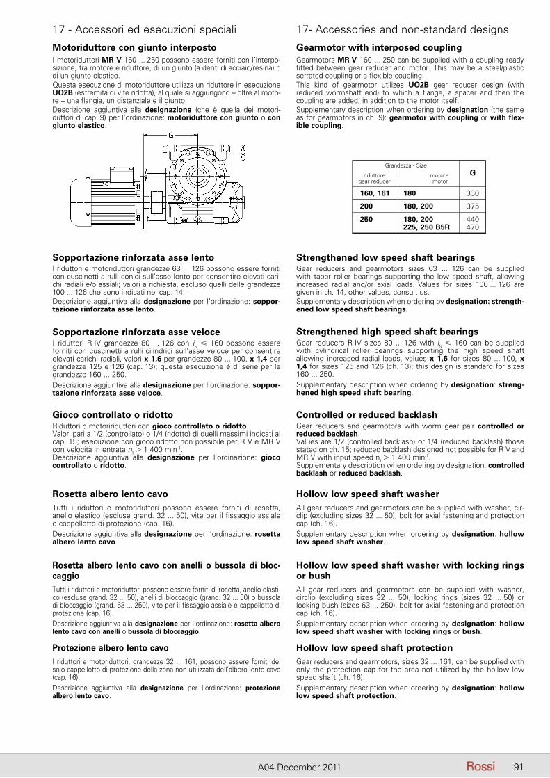
91A04 December 2011
Gearmotor with interposed couplingGearmotors MR V 160 ... 250 can be supplied with a coupling ready fitted between gear reducer and motor. This may be a steel/plastic serrated coupling or a flexible coupling.This kind of gearmotor utilizes UO2B gear reducer design (with reduced wormshaft end) to which a flange, a spacer and then the coupling are added, in addition to the motor itself.Supplementary description when ordering by designation (the same as for gearmotors in ch. 9): gearmotor with coupling or with flex-ible coupling.
Grandezza - Size
riduttore motore gear reducer motor
G
160, 161 180 330
200 180, 200 375
250 180, 200 440 225, 250 B5R 470
Motoriduttore con giunto interpostoI motoriduttori MR V 160 ... 250 possono essere forniti con l’interpo-sizione, tra motore e riduttore, di un giunto (a denti di acciaio/resina) o di un giunto elastico.Questa esecuzione di motoriduttore utilizza un riduttore in esecuzione UO2B (estremità di vite ridotta), al quale si aggiungono – oltre al moto-re – una flangia, un distanziale e il giunto.Descrizione aggiuntiva alla designazione (che è quella dei motori-duttori di cap. 9) per l’ordinazione: motoriduttore con giunto o con giunto elastico.
17 - Accessori ed esecuzioni speciali 17- Accessories and non-standard designs
Sopportazione rinforzata asse veloceI riduttori R IV grandezze 80 ... 126 con iN � 160 possono essere for niti con cuscinetti a rulli cilindrici sull’asse veloce per consentire elevati carichi radiali, valori x 1,6 per grandezze 80 ... 100, x 1,4 per grandezze 125 e 126 (cap. 13); questa esecuzione è di serie per le grandezze 160 ... 250.Descrizione aggiuntiva alla designazione per l’ordinazione: soppor-tazione rinforzata asse veloce.
Strengthened high speed shaft bearingsGear reducers R IV sizes 80 ... 126 with iN � 160 can be supplied with cylindrical roller bearings supporting the high speed shaft allowing increased radial loads, values x 1,6 for sizes 80 ... 100, x 1,4 for sizes 125 and 126 (ch. 13); this design is standard for sizes 160 ... 250.Supplementary description when ordering by designation: streng-hened high speed shaft bearing.
Sopportazione rinforzata asse lentoI riduttori e motoriduttori grandezze 63 ... 126 possono essere forniti con cuscinetti a rulli conici sull’asse lento per consentire elevati cari-chi radiali e/o assiali; valori a richiesta, escluso quelli delle grandezze 100 ... 126 che sono indicati nel cap. 14.Descrizione aggiuntiva alla designazione per l’ordinazione: soppor-tazione rinforzata asse lento.
Strengthened low speed shaft bearingsGear reducers and gearmotors sizes 63 ... 126 can be supplied with taper roller bearings supporting the low speed shaft, allowing increased radial and/or axial loads. Values for sizes 100 ... 126 are given in ch. 14, other values, consult us.Supplementary description when ordering by designation: strength-ened low speed shaft bearings.
Gioco controllato o ridottoRiduttori o motoririduttori con gioco controllato o ridotto.Valori pari a 1/2 (controllato) o 1/4 (ridotto) di quelli massimi indicati al cap. 15; esecuzione con gioco ridotto non possibile per R V e MR V con velocità in entrata n1
� 1 400 min-1.Descrizione aggiuntiva alla designazione per l’ordinazione: gioco controllato o ridotto.
Controlled or reduced backlashGear reducers and gearmotors with worm gear pair controlled or reduced backlash.Values are 1/2 (controlled backlash) or 1/4 (reduced backlash) those stated on ch. 15; reduced backlash designed not possible for R V and MR V with input speed n1
� 1 400 min-1.Supplementary description when ordering by designation: controlled backlash or reduced backlash.
Rosetta albero lento cavoTutti i riduttori o motoriduttori possono essere forniti di rosetta, anello elastico (escluse grand. 32 ... 50), vite per il fissaggio assiale e cappellotto di protezione (cap. 16).Descrizione aggiuntiva alla designazione per l’ordinazione: rosetta albero lento cavo.
Hollow low speed shaft washerAll gear reducers and gearmotors can be supplied with washer, cir-clip (excluding sizes 32 ... 50), bolt for axial fastening and protection cap (ch. 16).Supplementary description when ordering by designation: hollow low speed shaft washer.
Rosetta albero lento cavo con anelli o bussola di bloc-caggioTutti i riduttori e motoriduttori possono essere forniti di rosetta, anello elasti-co (escluse grand. 32 ... 50), anelli di bloccaggio (grand. 32 ... 50) o bussola di bloccaggio (grand. 63 ... 250), vite per il fissaggio assiale e cappellotto di protezione (cap. 16).Descrizione aggiuntiva alla designazione per l’ordinazione: rosetta albero lento cavo con anelli o bussola di bloccaggio.
Protezione albero lento cavoI riduttori e motoriduttori, grandezze 32 ... 161, possono essere forniti del solo cappellotto di protezione della zona non utilizzata dell’albero lento cavo (cap. 16).Descrizione aggiuntiva alla designazione per l’ordinazione: protezione albero lento cavo.
Hollow low speed shaft washer with locking rings or bushAll gear reducers and gearmotors can be supplied with washer, circlip (excluding sizes 32 ... 50), locking rings (sizes 32 ... 50) or locking bush (sizes 63 ... 250), bolt for axial fastening and protection cap (ch. 16).Supplementary description when ordering by designation: hollow low speed shaft washer with locking rings or bush.
Hollow low speed shaft protectionGear reducers and gearmotors, sizes 32 ... 161, can be supplied with only the protection cap for the area not utilized by the hollow low speed shaft (ch. 16).Supplementary description when ordering by designation: hollow low speed shaft protection.
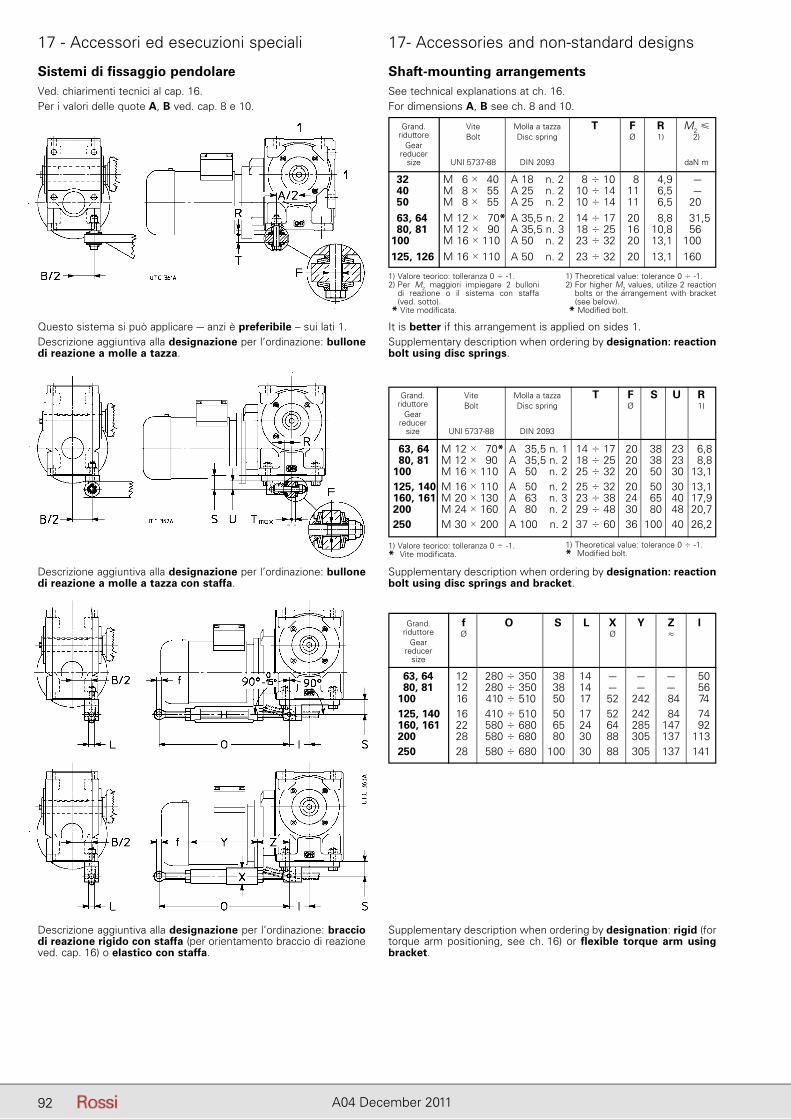
92 A04 December 2011
Sistemi di fissaggio pendolareVed. chiarimenti tecnici al cap. 16.Per i valori delle quote A, B ved. cap. 8 e 10.
Questo sistema si può applicare – anzi è preferibile – sui lati 1.Descrizione aggiuntiva alla designazione per l’ordinazione: bullone di reazione a molle a tazza.
It is better if this arrangement is applied on sides 1.Supplementary description when ordering by designation: reaction bolt using disc springs.
Descrizione aggiuntiva alla designazione per l’ordinazione: bullone di reazione a molle a tazza con staffa.
Supplementary description when ordering by designation: reaction bolt using disc springs and bracket.
Descrizione aggiuntiva alla designazione per l’ordinazione: braccio di reazione rigido con staffa (per orientamento braccio di reazione ved. cap. 16) o elastico con staffa.
Supplementary description when ordering by designation: rigid (for torque arm positioning, see ch. 16) or flexible torque arm using bracket.
Shaft-mounting arrangementsSee technical explanations at ch. 16.For dimensions A, B see ch. 8 and 10.
Grand. Vite Molla a tazza T F R M2 � riduttore Bolt Disc spring Ø 1) 2) Gear reducer size UNI 5737-88 DIN 2093 daN m
32 M 6 � 40 A 18 n. 2 8 � 10 8 4,9 – 40 M 8 � 55 A 25 n. 2 10 � 14 11 6,5 – 50 M 8 � 55 A 25 n. 2 10 � 14 11 6,5 20 63, 64 M 12 � 70* A 35,5 n. 2 14 � 17 20 8,8 31,5 80, 81 M 12 � 90 A 35,5 n. 3 18 � 25 16 10,8 56 100 M 16 � 110 A 50 n. 2 23 � 32 20 13,1 100 125, 126 M 16 � 110 A 50 n. 2 23 � 32 20 13,1 160
1) Valore teorico: tolleranza 0 � -1.2) Per M2 maggiori impiegare 2 bulloni
di reazione o il sistema con staffa (ved. sotto).
* Vite modificata.
1) Theoretical value: tolerance 0 � -1.2) For higher M2 values, utilize 2 reaction
bolts or the arrangement with bracket (see below).
* Modified bolt.
Grand. Vite Molla a tazza T F S U R riduttore Bolt Disc spring Ø 1) Gear reducer size UNI 5737-88 DIN 2093
63, 64 M 12 � 70* A 35,5 n. 1 14 � 17 20 38 23 6,8 80, 81 M 12 � 90 A 35,5 n. 2 18 � 25 20 38 23 8,8 100 M 16 � 110 A 50 n. 2 25 � 32 20 50 30 13,1 125, 140 M 16 � 110 A 50 n. 2 25 � 32 20 50 30 13,1 160, 161 M 20 � 130 A 63 n. 3 23 � 38 24 65 40 17,9 200 M 24 � 160 A 80 n. 2 29 � 48 30 80 48 20,7 250 M 30 � 200 A 100 n. 2 37 � 60 36 100 40 26,2
1) Valore teorico: tolleranza 0 � -1.* Vite modificata.
1) Theoretical value: tolerance 0 � -1.* Modified bolt.
Grand. f O S L X Y Z l riduttore Ø Ø ≈ Gear reducer size
63, 64 12 280 � 350 38 14 – – – 50 80, 81 12 280 � 350 38 14 – – – 56 100 16 410 � 510 50 17 52 242 84 74 125, 140 16 410 � 510 50 17 52 242 84 74 160, 161 22 580 � 680 65 24 64 285 147 92 200 28 580 � 680 80 30 88 305 137 113 250 28 580 � 680 100 30 88 305 137 141
17 - Accessori ed esecuzioni speciali 17- Accessories and non-standard designs

93A04 December 2011
pagina lasciata intenzionalmente biancapage intentionally left blank
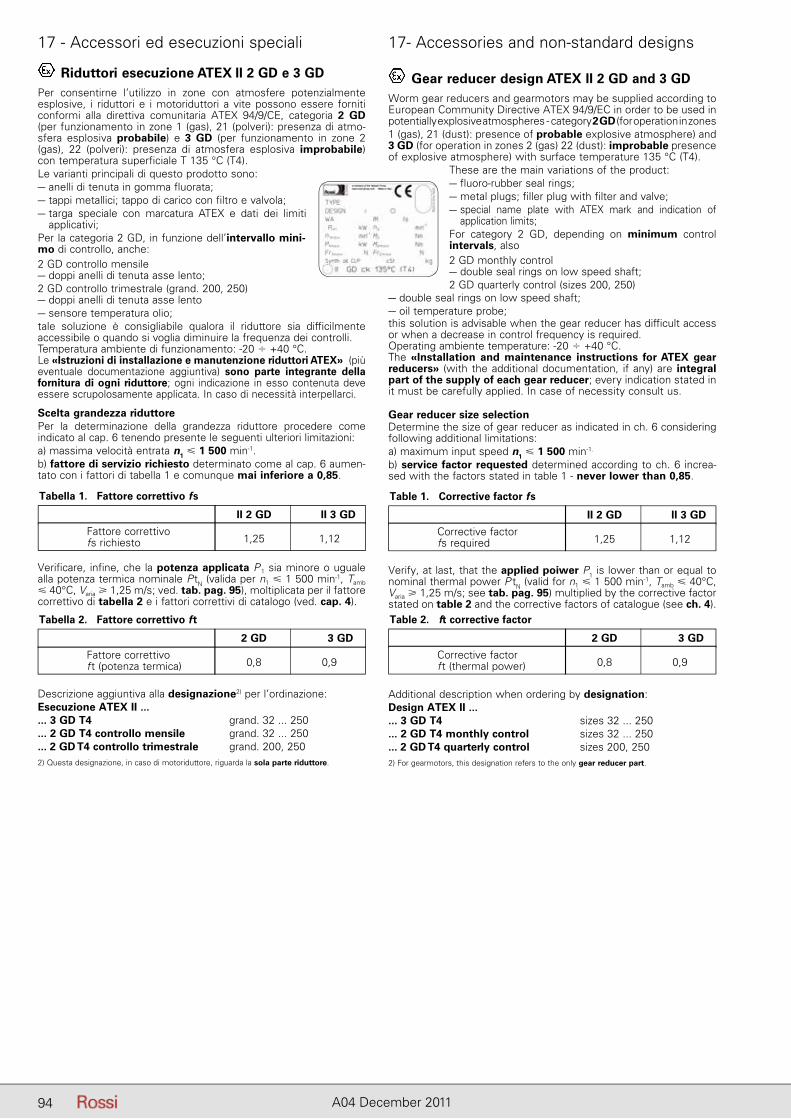
94 A04 December 2011
17 - Accessori ed esecuzioni speciali 17- Accessories and non-standard designs
Riduttori esecuzione ATEX II 2 GD e 3 GDPer consentirne l’utilizzo in zone con atmosfere potenzialmente esplosive, i riduttori e i motoriduttori a vite possono essere forniti conformi alla direttiva comunitaria ATEX 94/9/CE, categoria 2 GD (per funzionamento in zone 1 (gas), 21 (polveri): presenza di atmo-sfera esplosiva probabile) e 3 GD (per funzionamento in zone 2 (gas), 22 (polveri): presenza di atmosfera esplosiva improbabile) con temperatura superficiale T 135 °C (T4).Le varianti principali di questo prodotto sono:– anelli di tenuta in gomma fluorata;– tappi metallici; tappo di carico con filtro e valvola;– targa speciale con marcatura ATEX e dati dei limiti
applicativi;Per la categoria 2 GD, in funzione dell’intervallo mini-mo di controllo, anche:2 GD controllo mensile– doppi anelli di tenuta asse lento;2 GD controllo trimestrale (grand. 200, 250)– doppi anelli di tenuta asse lento– sensore temperatura olio;tale soluzione è consigliabile qualora il riduttore sia difficilmente accessibile o quando si voglia diminuire la frequenza dei controlli.Temperatura ambiente di funzionamento: -20 � +40 °C.Le «Istruzioni di installazione e manutenzione riduttori ATEX» (più eventuale documentazione aggiuntiva) sono parte integrante della fornitura di ogni riduttore; ogni indicazione in esso contenuta deve essere scrupolosamente applicata. In caso di necessità interpellarci.
Scelta grandezza riduttorePer la determinazione della grandezza riduttore procedere come indicato al cap. 6 tenendo presente le seguenti ulteriori limitazioni:a) massima velocità entrata n1 � 1 500 min-1.b) fattore di servizio richiesto determinato come al cap. 6 aumen-tato con i fattori di tabella 1 e comunque mai inferiore a 0,85.
Verificare, infine, che la potenza applicata P 1 sia minore o uguale alla potenza termica nominale P tN (valida per n1 � 1 500 min-1, Tamb � 40°C, Varia � 1,25 m/s; ved. tab. pag. 95), moltiplicata per il fattore correttivo di tabella 2 e i fattori correttivi di catalogo (ved. cap. 4).
Descrizione aggiuntiva alla designazione2) per l’ordinazione:Esecuzione ATEX II ...... 3 GD T4 grand. 32 ... 250... 2 GD T4 controllo mensile grand. 32 ... 250... 2 GD T4 controllo trimestrale grand. 200, 2502) Questa designazione, in caso di motoriduttore, riguarda la sola parte riduttore.
Tabella 1. Fattore correttivo fs
II 2 GD II 3 GD
Fattore correttivo fs richiesto 1,25 1,12
Tabella 2. Fattore correttivo ft
2 GD 3 GD
Fattore correttivo f t (potenza termica) 0,8 0,9
Gear reducer design ATEX II 2 GD and 3 GDWorm gear reducers and gearmotors may be supplied according to European Community Directive ATEX 94/9/EC in order to be used in potentially explosive atmospheres - category 2 GD (for operation in zones1 (gas), 21 (dust): presence of probable explosive atmosphere) and 3 GD (for operation in zones 2 (gas) 22 (dust): improbable presence of explosive atmosphere) with surface temperature 135 °C (T4).
These are the main variations of the product:– fluoro-rubber seal rings;– metal plugs; filler plug with filter and valve;– special name plate with ATEX mark and indication of
application limits;For category 2 GD, depending on minimum control intervals, also2 GD monthly control– double seal rings on low speed shaft;2 GD quarterly control (sizes 200, 250)
– double seal rings on low speed shaft;– oil temperature probe;this solution is advisable when the gear reducer has difficult access or when a decrease in control frequency is required.Operating ambiente temperature: -20 � +40 °C.The «Installation and maintenance instructions for ATEX gear reducers» (with the additional documentation, if any) are integral part of the supply of each gear reducer; every indication stated in it must be carefully applied. In case of necessity consult us.
Gear reducer size selectionDetermine the size of gear reducer as indicated in ch. 6 considering following additional limitations:a) maximum input speed n1 � 1 500 min-1.
b) service factor requested determined according to ch. 6 increa-sed with the factors stated in table 1 - never lower than 0,85.
Table 1. Corrective factor fs
II 2 GD II 3 GD
Corrective factor fs required 1,25 1,12
Verify, at last, that the applied poiwer P1 is lower than or equal to nominal thermal power P tN (valid for n1 � 1 500 min-1, Tamb � 40°C, Varia � 1,25 m/s; see tab. pag. 95) multiplied by the corrective factor stated on table 2 and the corrective factors of catalogue (see ch. 4).
Additional description when ordering by designation:Design ATEX II ...... 3 GD T4 sizes 32 ... 250... 2 GD T4 monthly control sizes 32 ... 250... 2 GD T4 quarterly control sizes 200, 2502) For gearmotors, this designation refers to the only gear reducer part.
Table 2. ft corrective factor
2 GD 3 GD
Corrective factor f t (thermal power) 0,8 0,9
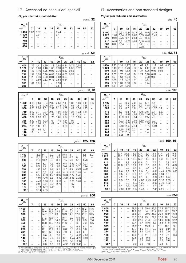
95A04 December 2011
17 - Accessori ed esecuzioni speciali 17- Accessories and non-standard designs
1) Per velocità nx comprese tra due valori tabulati (nsup, ninf), adottare il valore inferiore più vicino oppure interpolare: PtN-nx = (P tN-n sup- P tN-n inf)·(nx-ninf)/(nsup-ninf)+P tN-n inf2) Per nvite� 90 min-1, interpellarci.
1) For worm speed nxintemediate between two stated values (nsup, ninf), select the nearest lower value or interpolate: PtN-nx = (P tN-n sup- P tN-n inf)·(nx-ninf)/(nsup-ninf)+P tN-n inf2) For nworm� 90 min-1, consult us.
PtN per riduttori e motoriduttori PtN for gear reducers and gearmotorsgrand. 32
nvite 2)
worm
min-1 7 10 13 16 20 25 32 40 50 63 1 400 0,82 0,67 – – 0,44 – – – – – 1 120 – 0,61 – – 0,4 – – – – – 900 – – – – – – – – – – 710 – – – – – – – – – – 560 – – – – – – – – – – 450 – – – – – – – – – –
u vite worm
7 10 13 16 20 25 32 40 50 63
size 40 nvite
2)
worm
min-1
1 400 1,14 0,93 0,84 0,77 0,6 0,55 0,49 – – – 1 120 1,04 0,84 0,76 0,69 0,55 0,49 0,45 – – – 900 0,94 0,76 0,7 0,64 0,5 0,46 – – – – 710 0,87 0,7 0,63 0,58 0,45 0,41 – – – – 560 0,8 0,64 – – 0,41 – – – – – 450 – – – – 0,38 – – – – –
u vite worm
size 63, 64
7 10 13 16 20 25 32 40 50 63 1 400 2,73 2,34 1,97 1,81 1,67 1,3 1,17 1,08 0,96 – 1 120 2,49 2,13 1,79 1,64 1,5 1,17 1,06 0,97 – – 900 2,28 1,93 1,62 1,48 1,37 1,06 0,95 0,88 – – 710 2,07 1,75 1,46 1,34 1,24 0,96 0,87 – – – 560 1,9 1,61 1,34 1,23 – 0,88 0,8 – – – 450 1,76 1,48 1,24 1,14 – 0,82 – – – – 355 1,62 1,37 1,13 1,04 – 0,74 – – – – 280 1,51 1,27 1,06 – – – – – – –
u vite worm
nvite 2)
worm
min-1
grand. 50
7 10 13 16 20 25 32 40 50 63 1 400 1,72 1,4 1,29 1,18 0,92 0,84 0,76 0,68 – – 1 120 1,58 1,28 1,16 1,06 0,83 0,76 0,68 0,62 – – 900 1,43 1,16 1,05 0,96 0,75 0,69 0,63 – – – 710 1,31 1,05 0,96 0,88 0,69 0,63 0,57 – – – 560 1,2 0,96 0,88 0,81 0,63 0,58 – – – – 450 1,1 0,89 0,82 0,75 0,58 0,54 – – – – 355 1,01 0,81 – – 0,53 – – – – – 280 – – – – 0,5 – – – – –
nvite 2)
worm
min-1
u vite worm
7 10 13 16 20 25 32 40 50 63
size 250
1 400 – – – 48,5 41,2 39,4 35,5 27,3 25,7 23,2 1 120 – – – 42,2 36 34 30,2 23,8 22,1 19,7 900 – – – 36,8 31 29,6 25,9 20,4 18,9 16,8 710 – – – 31,2 26,4 25 22,2 17,3 16 14,4 560 – – – 26,9 22,8 21,4 18,8 14,9 13,6 12,2 450 – – – 23,4 19,7 18,6 16,3 12,8 11,8 10,6 355 – – – 20,2 17 15,9 14 11 10,1 9,1 280 – – – 17,7 14,9 14 12,3 9,6 8,9 8 224 – – – 15,8 13,1 12,4 11 8,5 7,9 7,2 180 – – – 14,2 11,8 11,1 9,8 7,7 7,1 6,4 140 – – – 12,5 10,3 9,8 – 6,7 6,2 – 112 – – – 11 9,1 8,6 – 5,9 5,6 – 90 1) – – – 9,9 8,3 7,8 – 5,4 5 –
nvite 2)
worm
min-1
u vite worm
grand. 200
7 10 13 16 20 25 32 40 50 63
1 400 – – 33,1 31,3 27 25,1 19,4 17,7 16,2 14,5 1 120 – – 28,6 26,9 23,2 21,5 16,7 15 13,9 12,3 900 – – 24,7 23,1 20 18,3 14,5 12,8 11,7 10,5 710 – – 21,2 19,9 17 15,7 12,2 10,9 10 8,9 560 – – 18,2 17 14,5 13,4 10,4 9,3 8,5 7,6 450 – – 15,8 14,7 12,6 11,6 9 8 7,3 6,5 355 – – 13,7 12,7 10,8 10 7,7 6,9 6,3 5,7 280 – – 12 11,2 9,5 8,8 6,8 6,1 5,6 – 224 – – 10,7 10 8,5 7,8 6 5,4 5 – 180 – – 9,6 9 7,6 7 5,4 4,85 4,52 – 140 – – 8,4 7,8 6,6 6,1 4,74 4,25 3,93 – 112 – – 7,5 7,1 5,9 5,5 4,17 3,83 – – 90 1) – – 6,8 6,3 5,3 4,93 3,79 3,46 – –
nvite 2)
worm
min-1
u vite worm
grand. 125, 126
7 10 13 16 20 25 32 40 50 63
1 400 – 15,2 14 12,2 11,2 10,4 8 7,1 6,6 5,9 1 120 – 13,1 11,9 10,3 9,5 8,8 6,7 6 5,6 – 900 – 11,3 10,2 8,9 8,1 7,5 5,8 5,1 4,76 – 710 – 9,6 8,7 7,5 6,9 6,4 4,89 4,36 4,03 – 560 – 8,3 7,4 6,4 5,8 5,4 4,17 3,7 3,44 – 450 – 7,2 6,4 5,6 5,1 4,7 3,6 3,21 2,99 – 355 – 6,2 5,6 4,81 4,4 4,11 3,12 2,81 – – 280 – 5,5 4,99 4,27 3,92 3,64 2,77 2,49 – – 224 – 4,91 4,46 3,81 3,49 3,24 2,48 2,23 – – 180 – 4,42 3,98 3,4 3,11 – 2,21 2,01 – – 140 – 3,9 3,51 3,01 2,75 – 1,97 – – – 112 – 3,48 3,14 2,68 – – 1,75 – – – 90 1) – 3,14 2,85 – – – – – – –
u vite worm nvite
2)
worm
min-1
size 160, 161
7 10 13 16 20 25 32 40 50 63
1 400 – 23,4 21,8 18,9 17,4 16,1 12,5 11,4 10,3 9,3 1 120 – 20,2 18,9 16,3 14,9 13,8 10,8 9,7 8,7 7,8 900 – 17,4 16,1 13,9 12,7 11,8 9,1 8,3 7,5 6,7 710 – 15 13,8 11,8 10,8 10 7,7 7 6,3 5,7 560 – 12,8 11,8 10,1 9,2 8,5 6,6 6 5,4 4,82 450 – 11,1 10,2 8,7 8 7,4 5,7 5,1 4,67 4,17 355 – 9,6 8,8 7,5 6,9 6,4 4,81 4,44 4,05 3,65 280 – 8,5 7,8 6,7 6,1 5,6 4,32 3,94 3,6 – 224 – 7,6 7 5,9 5,4 5 3,86 3,51 3,23 – 180 – 6,9 6,3 5,4 4,86 4,49 3,48 3,16 2,89 – 140 – 6 5,5 4,63 4,26 – 3,02 2,78 2,32 – 112 – 5,4 4,92 4,16 3,81 – 2,71 2,5 – – 90 1) – 4,81 4,42 3,74 3,43 – 2,46 2,25 – –
nvite 2)
worm
min-1
u vite worm
size 100
7 10 13 16 20 25 32 40 50 63
1 400 – 9,8 8,5 7,8 7,2 5,7 5,1 – – – 1 120 – 8,5 7,3 6,6 6,2 4,84 4,32 – – – 900 – 7,2 6,2 5,6 5,3 4,12 3,67 3,4 – – 710 – 6,2 5,3 4,8 4,45 3,5 3,11 2,87 – – 560 – 5,3 4,49 4,08 3,79 2,97 2,64 2,44 – – 450 – 4,59 3,9 3,54 3,3 2,56 2,3 – – – 355 – 4,02 3,41 3,09 2,89 2,24 2,01 – – – 280 – 3,55 3,01 2,76 2,57 1,99 1,79 – – – 224 – 3,18 2,69 2,44 – 1,78 1,59 – – – 180 – 2,88 2,42 2,21 – 1,6 – – – – 140 – 2,52 2,12 – – 1,4 – – – – 112 – 2,25 1,9 – – – – – – –
nvite 2)
worm
min-1
u vite worm
grand. 80, 81
7 10 13 16 20 25 32 40 50 63
1 400 4,15 3,59 3,04 2,82 2,58 2,1 1,83 1,66 1,49 1,32 1 120 3,82 3,28 2,76 2,54 2,34 1,82 1,65 1,5 1,35 – 900 3,51 2,99 2,51 2,31 2,11 1,65 1,49 1,36 1,23 – 710 3,17 2,7 2,27 2,09 1,91 1,49 1,35 1,23 1,11 – 560 2,89 2,46 2,06 1,89 1,75 1,36 1,22 1,13 – – 450 2,67 2,28 1,9 1,75 1,61 1,24 1,13 1,05 – – 355 2,47 2,09 1,73 1,6 1,49 1,14 1,04 – – – 280 2,31 1,94 1,61 1,49 – 1,06 0,96 – – – 224 2,11 1,8 1,5 – – 0,99 – – – – 180 1,98 1,69 1,4 – – – – – – – 140 1,8 – – – – – – – – – 112 – – – – – – – – – –
nvite 2)
worm
min-1
u vite worm
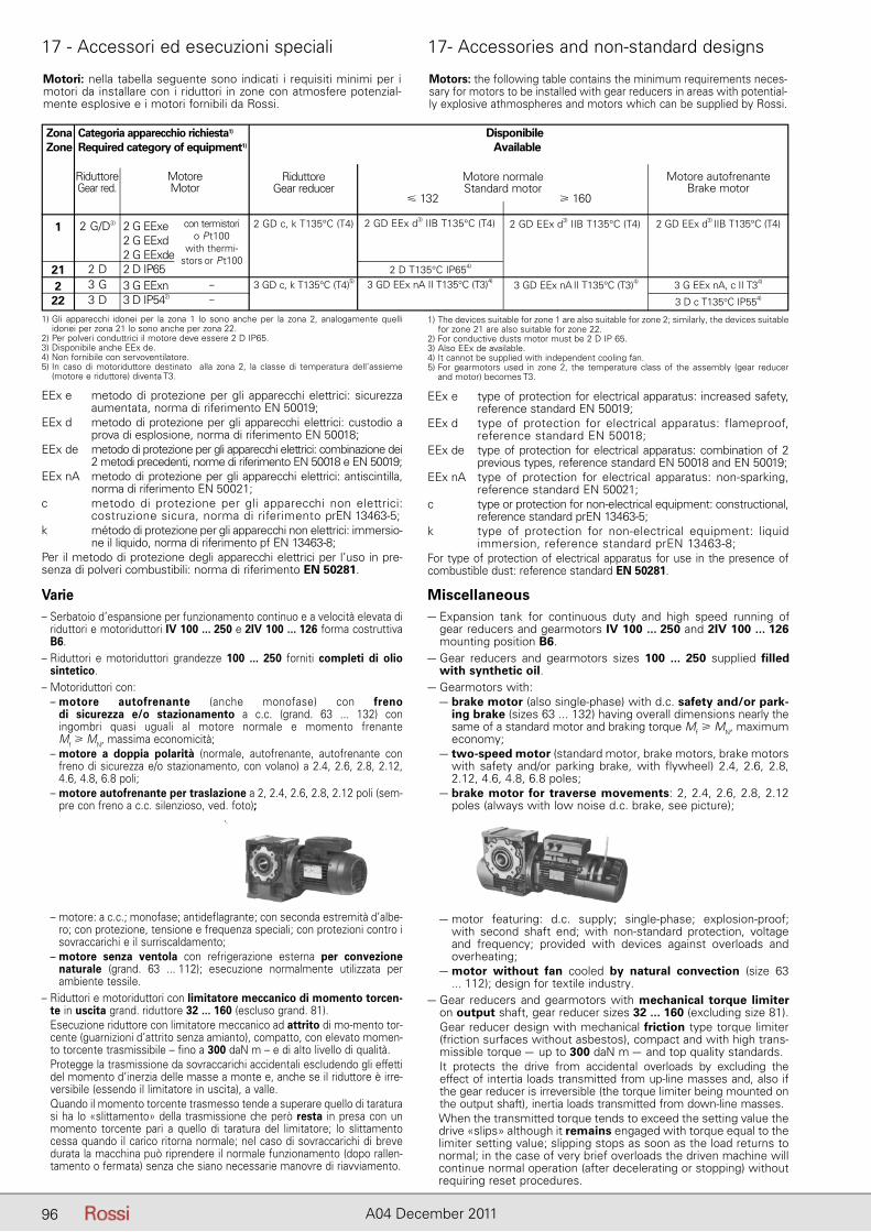
96 A04 December 2011
17 - Accessori ed esecuzioni speciali 17- Accessories and non-standard designs
– – motore: a c.c.; monofase; antideflagrante; con seconda estremità d’albe-ro; con protezione, tensione e frequenza speciali; con protezioni contro i sovraccarichi e il surriscaldamento;
– – motore senza ventola con refrigerazione esterna per convezione naturale (grand. 63 ... 112); esecuzione normalmente utilizzata per ambiente tessile.
– Riduttori e motoriduttori con limitatore meccanico di momento torcen-te in uscita grand. riduttore 32 ... 160 (escluso grand. 81).
– Esecuzione riduttore con limitatore meccanico ad attrito di mo-mento tor-cente (guarnizioni d’attrito senza amianto), compatto, con elevato momen-to torcente trasmissibile – fino a 300 daN m – e di alto livello di qualità.
– Protegge la trasmissione da sovraccarichi accidentali escludendo gli effetti del momento d’inerzia delle masse a monte e, anche se il riduttore è irre-versibile (essendo il limitatore in uscita), a valle.
– Quando il momento torcente trasmesso tende a superare quello di taratura si ha lo «slittamento» della trasmissione che però resta in presa con un momento torcente pari a quello di taratura del limitatore; lo slittamento cessa quando il carico ritorna normale; nel caso di sovraccarichi di breve durata la macchina può riprendere il normale funzionamento (dopo rallen-tamento o fermata) senza che siano necessarie manovre di riavviamento.
– – motor featuring: d.c. supply; single-phase; explosion-proof; with second shaft end; with non-standard protection, voltage and frequency; provided with devices against overloads and overheating;
– – motor without fan cooled by natural convection (size 63 ... 112); design for textile industry.
– Gear reducers and gearmotors with mechanical torque limiter on output shaft, gear reducer sizes 32 ... 160 (excluding size 81).
– Gear reducer design with mechanical friction type torque limiter (friction surfaces without asbestos), compact and with high trans-missible torque – up to 300 daN m – and top quality standards.
– It protects the drive from accidental overloads by excluding the effect of intertia loads transmitted from up-line masses and, also if the gear reducer is irreversible (the torque limiter being mounted on the output shaft), inertia loads transmitted from down-line masses.
– When the transmitted torque tends to exceed the setting value the drive «slips» although it remains engaged with torque equal to the limiter setting value; slipping stops as soon as the load returns to normal; in the case of very brief overloads the driven machine will continue normal operation (after decelerating or stopping) without requiring reset procedures.
Varie– Serbatoio d’espansione per funzionamento continuo e a velocità elevata di
riduttori e motoriduttori IV 100 ... 250 e 2IV 100 ... 126 forma costruttiva B6.
– Riduttori e motoriduttori grandezze 100 ... 250 forniti completi di olio sintetico.
– Motoriduttori con:– – motore autofrenante (anche monofase) con freno
di si curezza e/o stazionamento a c.c. (grand. 63 ... 132) con in gombri quasi uguali al motore normale e momento frenanteMf � MN, massima economicità;
– – motore a doppia polarità (normale, autofrenante, autofrenante con freno di sicurezza e/o stazionamento, con volano) a 2.4, 2.6, 2.8, 2.12, 4.6, 4.8, 6.8 poli;
– – motore autofrenante per traslazione a 2, 2.4, 2.6, 2.8, 2.12 poli (sem-pre con freno a c.c. silenzioso, ved. foto);
Miscellaneous– Expansion tank for continuous duty and high speed running of
gear reducers and gearmotors IV 100 ... 250 and 2IV 100 ... 126 mounting position B6.
– Gear reducers and gearmotors sizes 100 ... 250 supplied filled with synthetic oil.
– Gearmotors with:– – brake motor (also single-phase) with d.c. safety and/or park-
ing brake (sizes 63 ... 132) having overall dimensions nearly the same of a standard motor and braking torque Mf � MN, maximum economy;
– – two-speed motor (standard motor, brake motors, brake motors with safety and/or parking brake, with flywheel) 2.4, 2.6, 2.8, 2.12, 4.6, 4.8, 6.8 poles;
– – brake motor for traverse movements: 2, 2.4, 2.6, 2.8, 2.12 poles (always with low noise d.c. brake, see picture);
Motori: nella tabella seguente sono indicati i requisiti minimi per i motori da installare con i riduttori in zone con atmosfere potenzial-mente esplosive e i motori fornibili da Rossi.
Motors: the following table contains the minimum requirements neces-sary for motors to be installed with gear reducers in areas with potential-ly explosive athmospheres and motors which can be supplied by Rossi.
1) Gli apparecchi idonei per la zona 1 lo sono anche per la zona 2, analogamente quelli idonei per zona 21 lo sono anche per zona 22.
2) Per polveri conduttrici il motore deve essere 2 D IP65.3) Disponibile anche EEx de.4) Non fornibile con servoventilatore.5) In caso di motoriduttore destinato alla zona 2, la classe di temperatura dell’assieme
(motore e riduttore) diventa T3.
1) The devices suitable for zone 1 are also suitable for zone 2; similarly, the devices suitable for zone 21 are also suitable for zone 22.
2) For conductive dusts motor must be 2 D IP 65.3) Also EEx de available.4) It cannot be supplied with independent cooling fan.5) For gearmotors used in zone 2, the temperature class of the assembly (gear reducer
and motor) becomes T3.
Zona Categoria apparecchio richiesta1) Disponibile Zone Required category of equipment1) Available
1
212
22
2 G/D3)
2 D3 G3 D
2 G EExe2 G EExd2 G EExde2 D IP653 G EExn3 D IP542)
con termistorio P t100
with thermi-stors or P t100
–– 3 D c T135°C IP554)
RiduttoreGear red.
MotoreMotor
RiduttoreGear reducer
Motore normaleStandard motor
2 GD c, k T135°C (T4)
3 GD c, k T135°C (T4)5)
2 GD EEx d3) IIB T135°C (T4)
3 GD EEx nA II T135°C (T3)4)
Motore autofrenanteBrake motor
3 G EEx nA, c II T34)
2 GD EEx d3) IIB T135°C (T4)
3 GD EEx nA II T135°C (T3)4)
2 GD EEx d3) IIB T135°C (T4)
2 D T135°C IP654)
EEx e metodo di protezione per gli apparecchi elettrici: sicurezza aumentata, norma di riferimento EN 50019;
EEx d metodo di protezione per gli apparecchi elettrici: custodio a prova di esplosione, norma di riferimento EN 50018;
EEx de metodo di protezione per gli apparecchi elettrici: combinazione dei 2 metodi precedenti, norme di riferimento EN 50018 e EN 50019;
EEx nA metodo di protezione per gli apparecchi elettrici: antiscintilla, norma di riferimento EN 50021;
c metodo di protezione per gli apparecchi non elettrici: costruzione sicura, norma di riferimento prEN 13463-5;
k método di protezione per gli apparecchi non elettrici: immersio-ne il liquido, norma di riferimento pf EN 13463-8;
Per il metodo di protezione degli apparecchi elettrici per l’uso in pre-senza di polveri combustibili: norma di riferimento EN 50281.
EEx e type of protection for electrical apparatus: increased safety, reference standard EN 50019;
EEx d type of protection for electrical apparatus: flameproof, reference standard EN 50018;
EEx de type of protection for electrical apparatus: combination of 2 previous types, reference standard EN 50018 and EN 50019;
EEx nA type of protection for electrical apparatus: non-sparking, reference standard EN 50021;
c type or protection for non-electrical equipment: constructional, reference standard prEN 13463-5;
k type of protection for non-electrical equipment: liquid immersion, reference standard prEN 13463-8;
For type of protection of electrical apparatus for use in the presence of combustible dust: reference standard EN 50281.
� 132 � 160
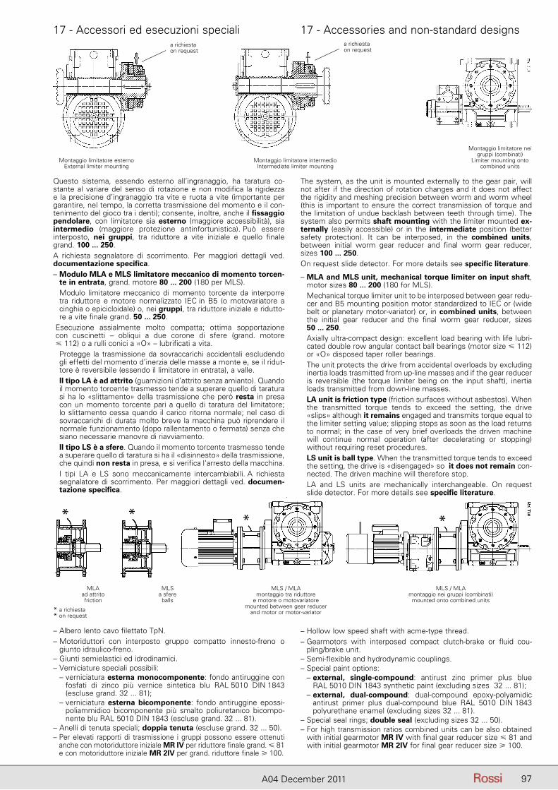
17 - Accessori ed esecuzioni speciali 17 - Accessories and non-standard designs
97A04 December 2011
The system, as the unit is mounted externally to the gear pair, will not after if the direction of rotation changes and it does not affect the rigidity and meshing precision between worm and worm wheel(this is important to ensure the correct transmission of torque and the limitation of undue backlash between teeth through time). The system also permits shaft mounting with the limiter mounted ex-ternally (easily accessible) or in the intermediate position (better safety protection). It can be interposed, in the combined units, between initial worm gear reducer and final worm gear reducer, sizes 100 ... 250.On request slide detector. For more details see specific literature.
– MLA and MLS unit, mechanical torque limiter on input shaft, motor sizes 80 ... 200 (180 for MLS).
– Mechanical torque limiter unit to be interposed between gear redu-cer and B5 mounting position motor standardized to IEC or (wide belt or planetary motor-variator) or, in combined units, between the initial gear reducer and the final worm gear reducer, sizes50 ... 250.
– Axially ultra-compact design: excellent load bearing with life lubri-cated double row angular contact ball bearings (motor size � 112) or «O» disposed taper roller bearings.
– The unit protects the drive from accidental overloads by excluding inertia loads trasmitted from up-line masses and if the gear reducer is reversible (the torque limiter being on the input shaft), inertia loads transmitted from down-line masses.
– LA unit is friction type (friction surfaces without asbestos). When the transmitted torque tends to exceed the setting, the drive «slips» although it remains engaged and transmits torque equal to the limiter setting value; slipping stops as soon as the load returns to normal; in the case of very brief overloads the driven machine will continue normal operation (after decelerating or stopping) without requiring reset procedures.
– LS unit is ball type. When the transmitted torque tends to exceed the setting, the drive is «disengaged» so it does not remain con-nected. The driven machine will therefore stop.
– LA and LS units are mechanically interchangeable. On request slide detector. For more details see specific literature.
– Hollow low speed shaft with acme-type thread.– Gearmotors with interposed compact clutch-brake or fluid cou-
pling/brake unit.– Semi-flexible and hydrodynamic couplings.– Special paint options:– – external, single-compound: antirust zinc primer plus blue
RAL 5010 DIN 1843 synthetic paint (excluding sizes 32 ... 81);– – external, dual-compound: dual-compound epoxy-polyamidic
antirust primer plus dual-compound blue RAL 5010 DIN 1843 polyurethane enamel (excluding sizes 32 ... 81).
– Special seal rings; double seal (excluding sizes 32 ... 50).– For high transmission ratios combined units can be also obtained
with initial gearmotor MR IV with final gear reducer size � 81 and with initial gearmotor MR 2IV for final gear reducer size � 100.
Questo sistema, essendo esterno all’ingranaggio, ha taratura co-stante al variare del senso di rotazione e non modifica la rigidezza e la precisione d’ingranaggio tra vite e ruota a vite (importante per garantire, nel tempo, la corretta trasmissione del momento e il con-tenimento del gioco tra i denti); consente, inoltre, anche il fissaggio pendolare, con limitatore sia esterno (maggiore accessibilità), sia intermedio (maggiore protezione antinfortunistica). Può essere interposto, nei gruppi, tra riduttore a vite iniziale e quello finale grand. 100 ... 250.A richiesta segnalatore di scorrimento. Per maggiori dettagli ved. documentazione specifica.– Modulo MLA e MLS limitatore meccanico di momento torcen-
te in entrata, grand. motore 80 ... 200 (180 per MLS).– Modulo limitatore meccanico di momento torcente da interporre
tra riduttore e motore normalizzato IEC in B5 (o motovariatore a cinghia o epicicloidale) o, nei gruppi, tra riduttore iniziale e ridutto-re a vite finale grand. 50 ... 250.–
Esecuzione assialmente molto compatta; ottima sopportazione con cuscinetti – obliqui a due corone di sfere (grand. motore� 112) o a rulli conici a «O» – lubrificati a vita.
– Protegge la trasmissione da sovraccarichi accidentali escludendo gli effetti del momento d’inerzia delle masse a monte e, se il ridut-tore è reversibile (essendo il limitatore in entrata), a valle.
– Il tipo LA è ad attrito (guarnizioni d’attrito senza amianto). Quando il momento torcente trasmesso tende a superare quello di taratura si ha lo «slittamento» della trasmissione che però resta in presa con un momento torcente pari a quello di taratura del limitatore; lo slittamento cessa quando il carico ritorna normale; nel caso di sovracca richi di durata molto breve la macchina può riprendere il normale funzionamento (dopo rallentamento o fermata) senza che siano ne cessarie manovre di riavviamento.
– Il tipo LS è a sfere. Quando il momento torcente trasmesso tende a superare quello di taratura si ha il «disinnesto» della trasmissione, che quindi non resta in presa, e si verifica l’arresto della macchina.
– I tipi LA e LS sono meccanicamente intercambiabili. A richiesta se gnalatore di scorrimento. Per maggiori dettagli ved. documen-tazione specifica.
MLS / MLAmontaggio tra riduttore
e motore o motovariatoremounted between gear reducer
and motor or motor-variator
MLS / MLAmontaggio nei gruppi (combinati)
mounted onto combined units
MLAad attrito friction
MLSa sfere balls
* a richiesta* on request
****
– Albero lento cavo filettato TpN.– Motoriduttori con interposto gruppo compatto innesto-freno o
giunto idraulico-freno.– Giunti semielastici ed idrodinamici.– Verniciature speciali possibili:– – verniciatura esterna monocomponente: fondo antiruggine con
fosfati di zinco più vernice sintetica blu RAL 5010 DIN 1843 (escluse grand. 32 ... 81);
– – verniciatura esterna bicomponente: fondo antiruggine epos si-poliammidico bicomponente più smalto poliuretanico bicompo-nente blu RAL 5010 DIN 1843 (escluse grand. 32 ... 81).
– Anelli di tenuta speciali; doppia tenuta (escluse grand. 32 ... 50).– Per elevati rapporti di trasmissione i gruppi possono essere ottenuti
anche con motoriduttore iniziale MR IV per riduttore finale grand. � 81 e con motoriduttore iniziale MR 2IV per grand. riduttore finale � 100.
Montaggio limitatore esternoExternal limiter mounting
Montaggio limitatore intermedioIntermediate limiter mounting
Montaggio limitatore neigruppi (combinati)
Limiter mounting ontocombined units
a richiestaon request
a richiestaon request
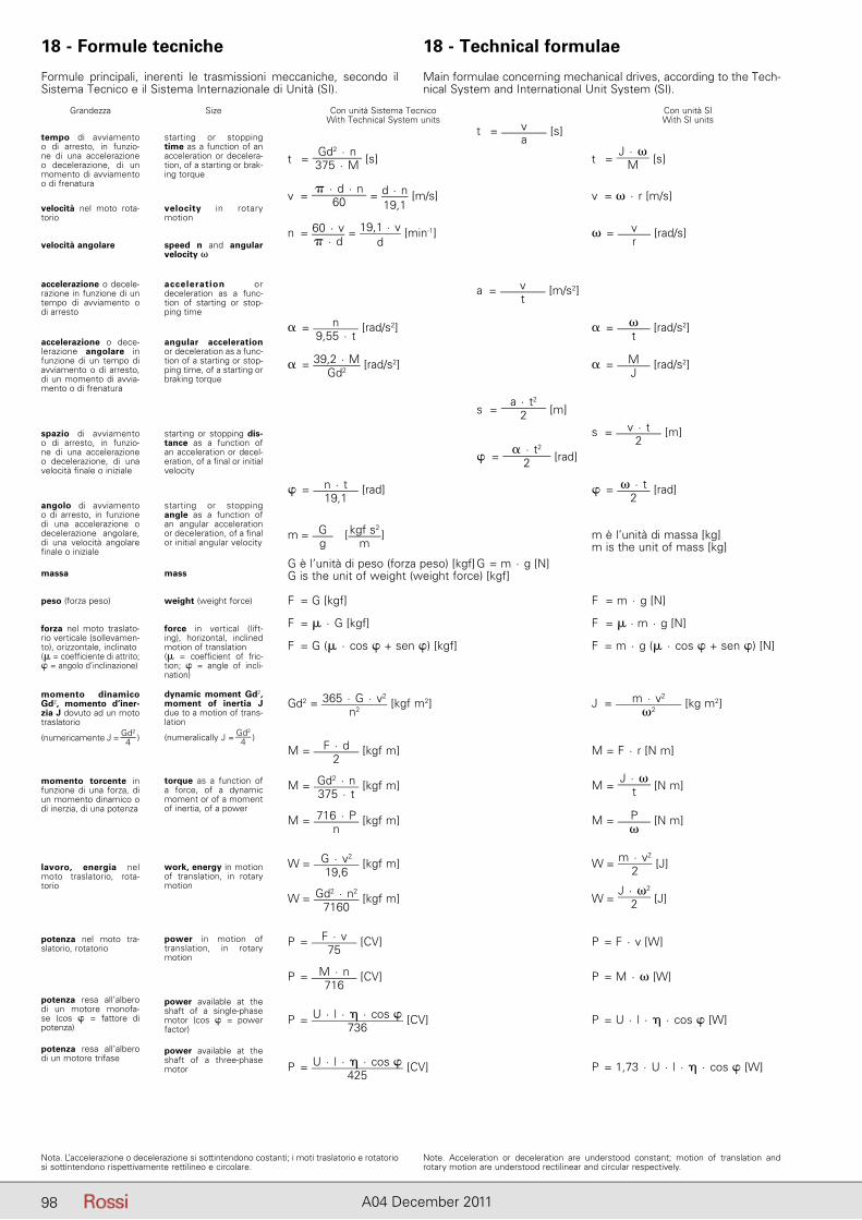
98 A04 December 2011
t = va
[s]
t = Gd2 · n375 · M [s] t =
J · �M [s]
v = � · d · n
60 = d · n19,1
[m/s] v = � · r [m/s]
n = 60 · v� · d
= 19,1 · vd
[min-1] � = vr
[rad/s]
a = vt
[m/s2]
� = n9,55 · t
[rad/s2] � = �t
[rad/s2]
� = 39,2 · MGd2
[rad/s2] � = MJ
[rad/s2]
s = a · t2
2 [m]
s = v · t2
[m]
� = � · t2
2 [rad]
� = n · t19,1
[rad] � = � · t2
[rad]
m = Gg
[ kgf s2
m] m è l’unità di massa [kg]
m is the unit of mass [kg]G è l’unità di peso (forza peso) [kgf] G = m · g [N]G is the unit of weight (weight force) [kgf]
F = G [kgf] F = m · g [N]
F = � · G [kgf] F = � · m · g [N]
F = G (� · cos � + sen �) [kgf] F = m · g (� · cos � + sen �) [N]
Gd2 = 365 · G · v2
n2 [kgf m2] J = m · v2
�2 [kg m2]
M = F · d2
[kgf m] M = F · r [N m]
M = Gd2 · n375 · t
[kgf m] M = J · �
t [N m]
M = 716 · Pn
[kgf m] M = P�
[N m]
W = G · v2
19,6 [kgf m] W = m · v2
2 [J]
W = Gd2 · n2
7160 [kgf m] W =
J · �2
2 [J]
P = F · v75
[CV] P = F · v [W]
P = M · n716
[CV] P = M · � [W]
P = U · l · � · cos �736
[CV] P = U · l · � · cos � [W]
P = U · l · � · cos �425
[CV] P = 1,73 · U · l · � · cos � [W]
Con unità Sistema Tecnico With Technical System units
Con unità SIWith SI units
Grandezza
tempo di avviamento o di arresto, in funzio-ne di una accelerazione o de celerazione, di un mo mento di avviamento o di frenatura
Size
starting or stopping time as a function of an ac celeration or decelera-tion, of a starting or brak-ing torque
velocità nel moto rota-torio
velocità angolare
accelerazione o decele-razione in funzione di un tempo di avviamento o di arresto
accelerazione o dece-lerazione angolare in funzione di un tempo di avviamento o di arresto, di un momento di avvia-mento o di frenatura
spazio di avviamento o di arresto, in funzio-ne di una accelerazione o de celerazione, di una velocità finale o iniziale
angolo di avviamento o di arresto, in funzione di una accelerazione o de celerazione angolare, di una velocità angolare fi nale o iniziale
massa
peso (forza peso)
forza nel moto traslato-rio verticale (sollevamen-to), orizzontale, inclinato(� = coefficiente di attrito; � = angolo d’inclinazione)
momento dinamico Gd2, momento d’iner-zia J dovuto ad un moto traslatorio
(numericamente J = Gd2
4 )
momento torcente in funzione di una forza, di un momento dinamico o di inerzia, di una potenza
lavoro, energia nel moto traslatorio, rota-torio
potenza nel moto tra-slatorio, rotatorio
potenza resa all’albero di un motore monofa-se (cos � = fattore di potenza)
potenza resa all’albero di un motore trifase
velocity in rotary mo tion
speed n and angular velocity �
acceleration or de celeration as a func-tion of starting or stop-ping time
angular acceleration or deceleration as a func-tion of a starting or stop-ping time, of a starting or braking torque
starting or stopping dis-tance as a function of an acceleration or decel-eration, of a final or initial velocity
starting or stopping angle as a function of an angular acceleration or deceleration, of a final or initial angular velocity
mass
weight (weight force)
force in vertical (lift-ing), horizontal, inclined mo tion of translation(� = coefficient of fric-tion; � = angle of incli-nation)
dynamic moment Gd2, moment of inertia J due to a motion of trans-lation
(numeralically J = Gd2
4 )
torque as a function of a force, of a dynamic mo ment or of a moment of inertia, of a power
work, energy in motion of translation, in rotary motion
power in motion of translation, in rotary motion
power available at the shaft of a single-phase motor (cos � = power factor)
power available at the shaft of a three-phase motor
18 - Formule tecniche 18 - Technical formulae
Formule principali, inerenti le trasmissioni meccaniche, secondo il Si stema Tecnico e il Sistema Internazionale di Unità (SI).
Main formulae concerning mechanical drives, according to the Tech-nical System and International Unit System (SI).
Nota. L’accelerazione o decelerazione si sottintendono costanti; i moti traslatorio e rota torio si sottintendono rispettivamente rettilineo e circolare.
Note. Acceleration or deceleration are understood constant; motion of translation and rotary motion are understood rectilinear and circular respectively.
99A04 December 2011
Indice delle revisioniElenco delle modifi che (Cat. A04 - Edition June 2011 disponibile su www.rossi-group.com)
Pag. 9, 11 :introdotti motori IE2
Elenco delle modifi che (Cat. A04 - Edition December 2011 disponi-bile su www.rossi-group.com)
Pag. 66 ... 77: inserite frecce bianche e nere per l’individuazione del senso di rotazione.
Pag. 78: aggiornato valore �m per i = 7 grand. 32.
Pag. 79: aggiornato limite da 2. MN2 a M2max.
Pag. 81: posizione tappi; modifi cata forma costruttiva da B7 a B61).
Pag. 87: introdotto sistema di reazione fl angia B14.
Pag. 88: aggiornati schemi di calcolo delle reazioni vincolari.
Pag. 89 : aggiornata UT.C fl angia B5.
Pag. 90: introdotta esecuzione «Flangia B5 tipo B».
Pag. 90: introdotta esecuzione «Braccio di reazione».
Pag. 90: introdotta esecuzione «Protezione albero lento cavo».
Pag. 91: eliminato accessorio «Flangia quadrata per servomotori».
Index of revisionsList of updates (Cat. A04 - Edition June 2011 available onwww.rossi-group.com)
Pages 9, 11 addition of IE2 motors
List of updates (Cat. A04 - Edition December 2011 available on www.rossi-group.com)
Page 66 ... 77: addition of black and white arrows for the identifi ca-tion of rotation direction.
Page 78: updating of value �m for i = 7 size 32.
Page 79: updating of limit from 2. MN2 to M2max.
Page 81: plug position; mounting position modifi ed from B7 to B61).
Page 87: addition of reaction arrangement onto B14 fl ange.
Page 88: updating of reaction forces calculation schemes.
Page 89: updating of UT.C B5 fl ange.
Page 90: addition of non-standard design «B5 fl ange type B».
Page 90: addition of non-standard design «Torque arm».
Page 90: addition of non-standard design «Hollow low speed shaft protection».
Page 91: elimination of accessory «Square fl ange for servomotors».
Registered trademarksCopyright Rossi S.p.A.Subject to alterationsPrinted in ItalyPublication dataEdition December 2011
Rossi S.p.A.
Via Emilia Ovest 915/A41123 Modena - ItalyPhone +39 059 33 02 88fax +39 059 82 77 74e-mail: [email protected]
Product liability, application considerations
The Customer is responsible for the correct selection and application of product in view of its industrial and/or commercial needs, unless the use has been recommended by technical qualifi ed personnel of Rossi, who were duly informed about customer’s application purposes. In this case all the necessary data required for the selection shall be communicated exactly and in writing by the Customer, stated in the order and confi rmed by Rossi. The Customer is always responsible for the safety of product applications. Every care has been taken in the drawing up of the catalog to ensure the accuracy of the information contained in this publication, however Rossi can accept no responsibility for any errors, omissions or outdated data. Due to the constant evolution of the state of the art, Rossi reserves the right to make any modifi cation whenever to this publication contents. The responsibility for the product selection is of the customer, excluding diff erent agreements duly legalized in writing and undersigned by the Parties.
Every decision we make at Rossi impacts the world we live in. But new technologies and renewed commitment to sustainable practices have provided us with the opportunity to make environmentally friendly printing decisions. Rossi catalogs are printed on Forest Stewardship CouncilTM (FSC®) certifi ed paper (1). This is a tangible commitment of Rossi in terms of environment sustainability.
(1) The certifi cation means that fi nished wood-based products in the marketplace have been handled by companies that have also been certifi ed and that the paper has been handled in an environmentally-friendly manner. The inks used are water-based for greater environmental protection.
Australia
Rossi Gearmotors Australia Pty. Ltd.e-mail: [email protected]/australia
Benelux
Rossi BeNeLux B.V.e-mail: [email protected]/benelux
Canada
Rossi North Americae-mail: [email protected]/northamerica
China
Rossi Gearmotors China P.T.I.e-mail: [email protected]/china
France Rossi Motoréducteurs SARLe-mail: [email protected]/france
Germany
Rossi GmbHe-mail: [email protected]/germany
India Rossi Gearmotors Pvt. Ltd.e-mail: [email protected]/india
Malaysia
Rossi Gearmotors South East Asia Sdn Bhde-mail: [email protected]/malaysia
New Zealand Rossi Gearmotors New Zealand Ltd.e-mail: [email protected]/australia
Poland
Rossi Polska Sp.z o.o.e-mail: [email protected]/poland
Spain, Portugal
Rossi Motorreductores S.L.e-mail: [email protected] www.rossi-group.com/spain
South Africa
Rossi Southern Africae-mail: [email protected]/southafrica
Taiwan
Rossi Gearmotors Co. Ltd. e-mail: [email protected]/taiwan
Turkey
Rossi Turkey & Middle Easte-mail: [email protected]/turkey
United Kingdom
Rossi Gearmotors Ltd.e-mail: [email protected] www.rossi-group.com/unitedkingdom
United States, Mexico
Rossi North Americae-mail: [email protected]/northamerica