JSV Piscaglia Libre
14
Development of a non-reflecting boundary condition for multidimensional nonlinear duct acoustic computation F. Piscaglia n , A. Montorfano, A. Onorati Dip. di Energia, Politecnico di Milano, Via Lambruschini 4, I-20156 Milano, Italy article info Article history: Received 28 July 2011 Received in revised form 7 September 2012 Accepted 10 September 2012 Handling Editor: D. Juve abstract The quality of any time-domain nonlinear CFD simulation of silencers is determined by the modeling procedure used for the anechoic termination at the boundary end of the computational domain. In this study, a novel anechoic boundary condition based on the characteristic theory combined with the linear relaxation method has been developed in an open source CFD code. Wave propagation in ducts and mufflers has been analyzed and the effect of the damping properties of the boundary condition has been studied. The study shows that the explicit damping of the solution vector produces good performance at all the frequencies with acoustic waves having varying incidence to the boundary. Also, results indicate that numerical reflection of acoustic waves with high incident angles is reduced if the damping is applied at the boundary within the semi-implicit solution of the governing equations. Finally, the boundary condition has been applied together with a nonlinear solver to evaluate the acoustic attenuation performance of circular flow-reversing chambers and single-plug perforated mufflers with and without mean flow velocity of the gas. Code validation has been carried out against experimental data. & 2012 Elsevier Ltd. All rights reserved. 1. Introduction A suitable compromise between high acoustic attenuation and low pressure drop represents the desirable characteristic of acoustic silencers and also the actual challenge for their designer. Nowadays, numerical models are often used for the fluid-dynamic and the acoustic optimization of the silencers. Among the different models available, those based upon one- dimensional acoustics (linear and nonlinear) are the most used, because of their very low computational cost. Their main limit is in the assumption of planar wave propagation, that does not hold when the contribution of the higher order modes is not negligible. When a more detailed description of the wave propagation within the silencer is required, multi- dimensional simulation looks as a reliable methodology to describe the features of realistic muffler geometries. In the linear acoustic theory, multidimensional simulation is performed by the finite element method (FEM) or by the boundary element method (BEM) with satisfactory results, in particular when no mean flow of the gas is considered. When simulations with mean gas flow velocity are performed by the linear approach, the acoustic field is superimposed over a decoupled mean flow imported from a steady-state calculation, where dissipative effects in the flow are neglected and only the convective effects are accounted for [1]. Finally, a further step is represented by the three-dimensional time- domain CFD approach, that accounts also for the dissipative effects of the mean flow on the sound propagation in silencers and resonators. The major advantages of the time-domain approach to calculate the transmission loss of complex silencers have been presented in other studies [2,3]. Contents lists available at SciVerse ScienceDirect journal homepage: www.elsevier.com/locate/jsvi Journal of Sound and Vibration 0022-460X/$ - see front matter & 2012 Elsevier Ltd. All rights reserved. http://dx.doi.org/10.1016/j.jsv.2012.09.030 n Corresponding author. Tel.: þ39 02 2399 8620; fax: þ39 02 2399 3863. E-mail address: [email protected] (F. Piscaglia). Journal of Sound and Vibration ] (]]]]) ]]]–]]] Please cite this article as: F. Piscaglia, et al., Development of a non-reflecting boundary condition for multidimensional nonlinear duct acoustic computation, Journal of Sound and Vibration (2012), http://dx.doi.org/10.1016/j.jsv.2012.09.030
description
good
Transcript of JSV Piscaglia Libre

Development of a non-reflecting boundary condition
for multidimensional nonlinear duct acoustic computation
F. Piscaglia n, A. Montorfano, A. Onorati
Dip. di Energia, Politecnico di Milano, Via Lambruschini 4, I-20156 Milano, Italy
a r t i c l e i n f o
Article history:
Received 28 July 2011
Received in revised form
7 September 2012
Accepted 10 September 2012
Handling Editor: D. Juve
a b s t r a c t
The quality of any time-domain nonlinear CFD simulation of silencers is determined by the
modeling procedure used for the anechoic termination at the boundary end of the
computational domain. In this study, a novel anechoic boundary condition based on the
characteristic theory combined with the linear relaxation method has been developed in an
open source CFD code. Wave propagation in ducts and mufflers has been analyzed and the
effect of the damping properties of the boundary condition has been studied. The study
shows that the explicit damping of the solution vector produces good performance at all
the frequencies with acoustic waves having varying incidence to the boundary. Also, results
indicate that numerical reflection of acoustic waves with high incident angles is reduced if
the damping is applied at the boundary within the semi-implicit solution of the governing
equations. Finally, the boundary condition has been applied together with a nonlinear
solver to evaluate the acoustic attenuation performance of circular flow-reversing
chambers and single-plug perforated mufflers with and without mean flow velocity of
the gas. Code validation has been carried out against experimental data.
& 2012 Elsevier Ltd. All rights reserved.
1. Introduction
A suitable compromise between high acoustic attenuation and low pressure drop represents the desirable characteristic
of acoustic silencers and also the actual challenge for their designer. Nowadays, numerical models are often used for the
fluid-dynamic and the acoustic optimization of the silencers. Among the different models available, those based upon one-
dimensional acoustics (linear and nonlinear) are the most used, because of their very low computational cost. Their main
limit is in the assumption of planar wave propagation, that does not hold when the contribution of the higher order modes
is not negligible. When a more detailed description of the wave propagation within the silencer is required, multi-
dimensional simulation looks as a reliable methodology to describe the features of realistic muffler geometries. In the
linear acoustic theory, multidimensional simulation is performed by the finite element method (FEM) or by the boundary
element method (BEM) with satisfactory results, in particular when no mean flow of the gas is considered. When
simulations with mean gas flow velocity are performed by the linear approach, the acoustic field is superimposed over a
decoupled mean flow imported from a steady-state calculation, where dissipative effects in the flow are neglected and
only the convective effects are accounted for [1]. Finally, a further step is represented by the three-dimensional time-
domain CFD approach, that accounts also for the dissipative effects of the mean flow on the sound propagation in silencers
and resonators. The major advantages of the time-domain approach to calculate the transmission loss of complex silencers
have been presented in other studies [2,3].
Contents lists available at SciVerse ScienceDirect
journal homepage: www.elsevier.com/locate/jsvi
Journal of Sound and Vibration
0022-460X/$ - see front matter & 2012 Elsevier Ltd. All rights reserved.
http://dx.doi.org/10.1016/j.jsv.2012.09.030
n Corresponding author. Tel.: þ39 02 2399 8620; fax: þ39 02 2399 3863.
E-mail address: [email protected] (F. Piscaglia).
Journal of Sound and Vibration ] (]]]]) ]]]–]]]
Please cite this article as: F. Piscaglia, et al., Development of a non-reflecting boundary condition for multidimensionalnonlinear duct acoustic computation, Journal of Sound and Vibration (2012), http://dx.doi.org/10.1016/j.jsv.2012.09.030
Similar to what happens in experiments, in nonlinear acoustic simulation the behavior of the anechoic termination
represents a crucial aspect to be considered. An anechoic termination is needed to not include reflections, downstream of the
silencer, in the pressure time histories that are recorded to be converted to the frequency domain for the determination of the
transmission loss (TL) of the silencer. The pressure time histories that are Fourier transformed must be only of waves traveling
from the inlet to the outlet of the system. In the measurements, the accuracy penalty due to the imperfect anechoic
terminations is still under study [4]. In the simulations, the accuracy penalty is easier to estimate and it leads to significant
errors. This aspect is more or less apparent depending on the nonlinear approach followed to simulate the silencer, but it
always occurs as a pressure far-field boundary condition is set at the outlet boundary. In one-dimensional simulation, the
numerical reflection coming from the outlet to the inner domain is very low when compared to the error introduced by the
assumption of one-dimensional flow. The same holds for quasi-three-dimensional approaches [5], where the result is mainly
influenced by the number of zero-dimensional volumes used for domain discretization rather than by the kind of non-
reflecting boundary model. In multidimensional nonlinear acoustic simulation, where the complete form of the Navier–Stokes
equations is solved, the nature and the kind of implementation of the boundary conditions becomes very important;
boundaries may cause artificial wave reflections, which may include both physical waves and numerical waves, in particular
when the non-reflective scheme does not account for full inter-field coupling.
To try to overcome this issue, in [6] the multidimensional domain of the silencer was coupled with a one-dimensional
long outlet pipe having an anechoic termination. Similarly, in [3] silencers were modeled with long inlet and outlet pipes
in three dimensions, to allow the reflected waves from the inlet and outlet boundaries to arrive at the monitoring points at
a time after which all the necessary acoustic data were recorded. In this latter case, the long pipes cause a significant
increase of the number of computational cells and, therefore, the computational time required by the simulation becomes
higher. A more efficient methodology, compatible with common computer resource limits, consists in removing the
computational domain that is not of primary interest (long inlet and outlet pipes for instance). In this case, the number of
computational cells is much lower and the accuracy of unsteady flow calculations strongly relies on the treatment of
boundary conditions.In most of the CFD codes, the non-reflecting boundary conditions attempt to set the instantaneous
value on the boundary as consistent as possible with the value of the incident pressure wave, to create a tendency towards
the undisturbed pressure value p1 defined over an ideal surface, located at an arbitrary distance L1 from the boundary.
The larger the value of L1, the further the boundary condition will deviate from p1. On the other hand, the smaller is the
value of L1, the more reflective the boundary tends to be. The cut boundaries may cause artificial wave reflections, that
appear as high frequency noise in the instantaneous pressure and velocity traces. In authors’ experience, the applicability
of the far-field boundary condition for calculations of the transmission loss is still valid up to a frequency of about 1600–
1800 Hz, depending on the complexity of the configuration. This is also confirmed by the results shown in [2].
In this work, in order to extend the reliability of the multidimensional nonlinear approach to a wider frequency range,
the anechoic termination has been modeled by a non-reflecting outflow Navier–Stokes characteristic boundary condition
(NSCBC) for the numerical solution of the time dependent compressible Navier–Stokes equations. The boundary condition
has been implemented by the authors in an open-source CFD code [7] and it has been tested together with a time
dependent compressible fully parallel Navier–Stokes equation solver. The original local one-dimensional inviscid relations
(LODI) in Cartesian coordinates presented in [8] have been extended to local coordinates and have been solved by a
multistage time stepping scheme. A formulation of the linear relaxation term, which should appear fully non-reflecting to
plane acoustic waves with normal incidence on the boundaries for all frequencies, has been tested.
The paper is organized as follows: the mathematical formulation of the NSCBC and the implementation of a non-
reflecting condition to achieve a well-posed problem are discussed. Then, the performance in duct acoustic application is
analyzed, by using a wave splitting method based on characteristic analysis. Finally, the boundary condition together with
a nonlinear solver has been applied to predict the acoustic attenuation performance of silencers with zero and non-zero
mean flow velocity of the gas. Conclusions are given in the final section.
2. Formulation of the NSCBC framework in local Cartesian coordinates
In the NSCBC theory [9], variables which are not imposed by physical boundary conditions are computed on the
boundaries by solving the conservation equations as in the domain [8]. Wave propagation is assumed to be associated only
with the hyperbolic part of the Navier–Stokes equations by neglecting waves associated with the diffusion process. At high
Reynolds numbers this approximation is probably well justified, but at low Reynolds numbers the mathematical
justification may be questionable. In spite of this, simulation results at low Reynolds numbers look satisfying, as shown
in the section of the results. The system of governing equations, in Cartesian coordinates is
qr
qtþr � ru¼ 0
qru
qtþr � ½uðruÞ�þrp¼r � T
qrE
qtþr � ½uðrEÞ�þr � ðupÞ ¼r � T � u�r � q
8
>
>
>
>
>
>
<
>
>
>
>
>
>
:
(1)
Please cite this article as: F. Piscaglia, et al., Development of a non-reflecting boundary condition for multidimensionalnonlinear duct acoustic computation, Journal of Sound and Vibration (2012), http://dx.doi.org/10.1016/j.jsv.2012.09.030
F. Piscaglia et al. / Journal of Sound and Vibration ] (]]]]) ]]]–]]]2

where
rE¼ 1
2ruk � ukþ
p
g�1(2)
and T is the viscous stress tensor, whose elements are defined as
ti,j ¼ mqui
qxjþ
quj
qxi�2
3dij
quk
qxk
� �
(3)
In the above equations, p is the thermodynamic pressure, mi is the momentum density in the xi direction, rE is the total
energy density (kineticþthermal), q is the conductive heat flux:
q¼�lrT (4)
where T is the gas temperature and l is the thermal conductivity, that is expressed as a function of the specific heat
capacity cp of the gas and of the Prandtl number Pr:
l¼ mcpPr
(5)
In this work, the formulation of the characteristic boundary condition treatment for Navier–Stokes equations (NSCBC)
originally suggested in Cartesian coordinates by Poinsot and Lele [8] has been extended to local coordinates and it has
been solved by a multistage time stepping scheme. For each cell face at the boundary end, a local reference frame (x, Z, z)has been defined. Each reference frame has its origin in the cell face center and the vector z is set as perpendicular to the
cell face (Fig. 1).
To transform the conservative system (1) from a physical domain (x, Z, z) to a computational domain (x, y, z), a change
of variables is required because, as it will be discussed later, the characteristic theory to include in the compressible
subsonic Navier–Stokes equations refers to a wave element that is perpendicular to the outlet domain. Hence, the
following general transformation of the independent variables has been applied:
x¼ xðx,Z,zÞy¼ yðx,Z,zÞz¼ zðx,Z,zÞ (6)
Being ui the flow velocity in the local reference frame:
u1 ¼ ux
u2 ¼ uZ
u3 ¼ uz (7)
and the momentum density in the i-th direction (still written for the local reference frame):
mi ¼ r � ui (8)
For a generic boundary end, under the assumption of inviscid flow, the system of governing equations (1) in local
coordinates takes the form:
Mass conservation
qr
qtþd1þ
qm2
qZþ qm3
qz¼ 0 (9)
Fig. 1. For each cell face at the boundary end, a local reference frame (x, Z, z) has been defined; each reference frame has its origin in the cell face center
with the vector z perpendicular to the cell face.
Please cite this article as: F. Piscaglia, et al., Development of a non-reflecting boundary condition for multidimensionalnonlinear duct acoustic computation, Journal of Sound and Vibration (2012), http://dx.doi.org/10.1016/j.jsv.2012.09.030
F. Piscaglia et al. / Journal of Sound and Vibration ] (]]]]) ]]]–]]] 3

Energy equation
qrE
qtþ 1
2ðuk � ukÞd1þ
d2g�1
þm1d3þm2d4þm3d5þq½ðrEþpÞu2�
qZþ q½ðrEþpÞu3�
qz¼�r � qþ
qujtijqxi
(10)
Momentum equations
qm1
qtþu1d1þrd3þ
qm1u2
qZþ qm1u3
qz¼
qt1jqxj
qm2
qtþu2d1þrd4þ
qm2u2
qZþ qm2u3
qz¼� qp
qZþ
qt2jqxj
qm3
qtþu3d1þrd5þ
qm3u2
qZþ qm3u3
qz¼� qp
qzþ
qt3jqxj
(11)
The different terms of the system of Eqs. (11) contain derivatives normal to the boundary (d1–d5) and derivatives
parallel to the boundary like ðq=qZÞðm2uZÞ.According to the characteristic analysis of Thompson [10], the vector d can be written as
d¼
d1
d2
d3
d4
d5
2
6
6
6
6
6
6
4
3
7
7
7
7
7
7
5
¼
1c2½L2þ 1
2 ðL5þL1Þ�12 ðL5þL1Þ1
2rc ðL5�L1ÞL3
L4
2
6
6
6
6
6
6
6
4
3
7
7
7
7
7
7
7
5
¼
qm1
qx
qc2m1
qxþu1
qpqx
u1qu1
qxþ 1
rqpqx
u1qu2
qx
u1qu3
qx
2
6
6
6
6
6
6
6
6
6
4
3
7
7
7
7
7
7
7
7
7
5
(12)
where Li represents the amplitude variation of the ith characteristic wave crossing the boundary [9]:
L¼
L1
L2
L3
L4
L5
2
6
6
6
6
6
6
4
3
7
7
7
7
7
7
5
¼
l1qpqx�rc qu1
qx
� �
l2 c2 qrqx� qp
qx
� �
l3qu2
qx
l4qu3
qx
l5qpqx
þrc qu1qx
� �
2
6
6
6
6
6
6
6
6
6
6
6
4
3
7
7
7
7
7
7
7
7
7
7
7
5
(13)
Li are the amplitudes of characteristic waves associated with each characteristic velocity li:
l1 ¼ u1�c
l2 ¼ l3 ¼ l4 ¼ u1
l5 ¼ u1þc
8
>
<
>
:
(14)
In particular, in (14), c is the local speed of sound, l1 and l5 are the velocity of sound waves moving along the positive and
negative stream-wise direction, l2 is the velocity for entropy advection, while l3 and l4 are the velocity at which u2 and u3are advected in the x direction.
The complete system of governing Eqs. (9)–(11) for compressible and viscous flows can therefore be written at the
boundary as
qr
qtþ 1
c2L2þ
1
2ðL5þL1Þ
� �
þqm2
qZþqm3
qz¼ 0
qp
qtþ1
2ðL5þL1Þþ
q½ðrEþpÞu2�qZ
q½ðrEþpÞu3�qz
¼�r � q
qu1
qtþ 1
2rcðL5�L1Þþ
qm1u2
qZþqm1u3
qz¼ 0
qu2
qtþL3þ
qm2u2
qZþqm2u3
qz¼�qp
qZ
qu3
qtþL4þ
qm3u2
qZþqm3u3
qz¼�qp
qz
8
>
>
>
>
>
>
>
>
>
>
>
>
>
>
>
>
>
<
>
>
>
>
>
>
>
>
>
>
>
>
>
>
>
>
>
:
The chain rule for changing variables in Eq. (1) requires the operators:
qð Þqx
¼ qð Þqx
xxþqð Þqy
yxþqð Þqz
zx
qð ÞqZ
¼ qð Þqx
xZþqð Þqy
yZþqð Þqz
zZ
Please cite this article as: F. Piscaglia, et al., Development of a non-reflecting boundary condition for multidimensionalnonlinear duct acoustic computation, Journal of Sound and Vibration (2012), http://dx.doi.org/10.1016/j.jsv.2012.09.030
F. Piscaglia et al. / Journal of Sound and Vibration ] (]]]]) ]]]–]]]4

qð Þqz
¼ qð Þqx
xzþqð Þqy
yzþqð Þqz
zz (15)
The partial derivatives in these equations occur in the differential expressions:
dx
dy
dz
2
6
4
3
7
5¼
xx xZ xz
yx yZ yz
zx zZ zz
2
6
4
3
7
5
dx
dZ
dz
2
6
4
3
7
5(16)
In a similar manner, from the inverse transformation equations, the differentials can be derived as
dx
dZ
dz
2
6
4
3
7
5¼
xx xy xz
Zx Zy Zz
zx zy zz
2
6
6
4
3
7
7
5
dx
dy
dz
2
6
4
3
7
5(17)
The transformations (16) and (17) are inverse of each other and so we can write:
xx xZ xz
yx yZ yz
zx zZ zz
2
6
4
3
7
5¼
xx xy xz
Zx Zy Zz
zx zy zz
2
6
6
4
3
7
7
5
�1
¼ 9J9 �Zyzz�Zzzy xzzy�xyzz Zzxy�Zy xz
Zzzx�Zxzz xxzz�xzzx Zxxz�Zz xx
Zxzy�Zyzx xyzx�xxzy Zyxx�Zx xy
2
6
6
4
3
7
7
5
(18)
where 9J9 is the determinant of the Jacobian matrix J, not singular:
J ¼
qxqx
qxqy
qxqz
qZqx
qZqy
qZqz
qzqx
qzqy
qzqz
2
6
6
6
4
3
7
7
7
5
(19)
By comparing like elements in Eq. (18) it follows:
xx ¼ 9J9ðZyzz�ZzzyÞxZ ¼ 9J9ðZzzx�ZxzzÞxz ¼ 9J9ðZxzy�ZyzxÞyx ¼ 9J9ðxzzy�xyzzÞyZ ¼ 9J9ðxxzz�xzzxÞyz ¼ 9J9ðxyzx�xxzyÞzx ¼ 9J9ðZzxy�ZyxzÞzZ ¼ 9J9ðZxxz�ZzxxÞzz ¼ 9J9ðZyxx�ZxxyÞ (20)
The governing equations may be therefore written as
qU
qtþqF1
qxþ qF2
qyþ qF3
qz¼�rp (21)
where
U ¼ U
9J9
qF1
qx¼ F 1xxþ F 2xZþ F 3xz
9J9
qF2
qy¼
F 1yxþ F 2yZþ F 3yz
9J9
qF3
qz¼ F 1zxþ F 2zZþ F 3zz
9J9(22)
If we compare the system equations (9)–(11) with Eqs. (21) and (22), it follows:
^qF1
qx¼
rd1ru1d1þrd3ru2d1þrd4ru3d1þrd5
12 ðuk � ukÞd1þ d2
g�1 þm1d3þm2d4þm3d5
2
6
6
6
6
6
6
6
4
3
7
7
7
7
7
7
7
5
(23)
Please cite this article as: F. Piscaglia, et al., Development of a non-reflecting boundary condition for multidimensionalnonlinear duct acoustic computation, Journal of Sound and Vibration (2012), http://dx.doi.org/10.1016/j.jsv.2012.09.030
F. Piscaglia et al. / Journal of Sound and Vibration ] (]]]]) ]]]–]]] 5

^qF2
qZ¼
qm2
qx2
qm1u2
qx2
qm2u2qx2
þ qpqZ
qm3u2
qx2
q½ðrEþpÞu2 �qx2
2
6
6
6
6
6
6
6
6
6
4
3
7
7
7
7
7
7
7
7
7
5
(24)
^qF3
qz¼
qm3
qx3
qmxu3
qx3
qm2u3
qx3
qm3u3qx3
þ qpqz
q½ðrEþpÞu3 �qx3
2
6
6
6
6
6
6
6
6
6
4
3
7
7
7
7
7
7
7
7
7
5
(25)
3. Non-reflecting boundary model
The implementation of the non-reflecting boundary condition to model an anechoic termination requires some caution.
The NSCBC approach sets values for the wave amplitude variations in the viscous multidimensional case by examining
a local one-dimensional inviscid (LODI) problem [8], where transverse, viscous and reaction terms are neglected:
qr
qtþ 1
c2L2þ
1
2ðL5þL1Þ
� �
¼ 0
qp
qtþ1
2ðL5þL1Þ ¼ 0
qu1
qtþ 1
2rcðL5�L1Þ ¼ 0
qu2
qtþL3 ¼ 0
qu3
qtþL4 ¼ 0
8
>
>
>
>
>
>
>
>
>
>
>
>
>
>
>
>
<
>
>
>
>
>
>
>
>
>
>
>
>
>
>
>
>
:
For subsonic flows at the exit, the eigenvalue l1 ¼ u1�C in (14) associated to the wave amplitude L1 is negative and the
disturbance travels inward the boundary at the speed of sound relative to the moving fluid.
The application of the LODI relations into the Navier–Stokes equations, that does not necessarily always imply a
hyperbolic nature of the system, is questionable. In particular, if the ingoing characteristic is set to zero (perfect anechoic
condition), the problem results to be ill-posed and the information about the static pressure in the outer domain never feds
back into the computational domain [11–13]. For a well-posed problem [11], corrections must be added to the treatment
of the non-reflecting NSCBC, that becomes therefore partially reflective. It is important to note that partial reflection also
includes the contributions of spurious reflections caused by the numerical approximation of hyperbolic equations at the
boundary [14]; this effect looks stronger if inviscid boundary conditions for the primitive variables are specified and if
transverse terms in the equations are neglected. The acoustic theory proposed to characterize the actual reflection
coefficient of numerical ‘‘non-reflecting’’ boundary condition using LRM (linear relaxation method) proposed by Rudy and
Strikwerda [11] has been applied to derive a formulation of the reflected characteristic in generalized coordinates [15]:
L1 ¼ K � ðp�p1Þ ¼ s � 91�M29ffiffiffi
2p
Jrlðp�p1Þ (26)
that has been included in Eq. (12). In Eq. (26),M is the local Mach number of the boundary cell, l is the characteristic length
of the domain. The preferred range for constant s is in the interval ½0:1; p�. The difference L5�L1 in Eq. (12) can be still
calculated by one side upwind differencing.
4. Formulation of the solver
The explicit solution proposed in [8] to solve Eqs. (9)–(11) requires very small time steps for stability and would
therefore result in a very severe restriction for the global time step of the simulation. In the present study, the system of
equations written in the form of (21) has been solved by a multistage time stepping scheme in
tn,i � tnþ i � dt¼ tnþ iDt
nsteps, i 2 ½1;nsteps� (27)
Please cite this article as: F. Piscaglia, et al., Development of a non-reflecting boundary condition for multidimensionalnonlinear duct acoustic computation, Journal of Sound and Vibration (2012), http://dx.doi.org/10.1016/j.jsv.2012.09.030
F. Piscaglia et al. / Journal of Sound and Vibration ] (]]]]) ]]]–]]]6

where tn,i is a variable local fractional time-step, in order to improve the time accuracy. In the expression above, Dt is the
global time step, K is the total number of fractional time steps. The method consists of two main steps:
� a first step is used to evaluate from the old time tn backward spatial derivatives and fluxes at time tnþ iDt=nsteps, where
i¼ ½1,nsteps�; conservation equations are solved sequentially and the solution is first order in time;
� fluxes and source terms calculated at tnþ iDt=nsteps are used to find the solution at time tnþðiþ1ÞDt=nsteps. The time
accuracy of this method is of the second order at this stage.
The process is iterated until the solution at the new time tnþ1 � tþDt is calculated. The Gauss theorem has been used to
compute spatial derivatives over the surface of the boundary, while along the z direction one-sided differences have to be
used because grid points are available only on the interior side of the boundary. This causes a decrease in the accuracy of
the spatial derivatives near the boundaries; on the other hand, if the order of the approximation near the boundary is equal
to the scheme order minus one, the overall accuracy of the scheme is not affected [16]. The time stepping algorithm
requires a relatively small amount of memory storage, it is more stable and accurate and it allows for larger global time
steps in the simulation than a traditional explicit method.
5. Performance of the non-reflecting boundary condition
The performance of non-reflecting boundary conditions can depend on a number of different factors [17]: the cut-off
ratio, the ratio between frequency and wavelength (gas sound velocity), the angle of the incident waves relative to the
boundary normal, the mean flow velocity, the damping constant s of the LRM. Also, numerical reflection can depend on
the solution algorithm used. The cut-off ratio includes both the effect of the wave frequency content and of the wave angle
a, that is defined as the angle between the wavefront normal and the outward normal to the boundary edge (Fig. 2).
In this study, the effect of these parameters on the performance of the boundary condition was investigated, for a fixed
value of the damping constant s in (26), that was set to 0.2. This choice was driven by the idea to evaluate the predictions
of the physical model; also, in author’s experience, s¼ 0:2 represents a good compromise to have low reflections from the
boundary and to avoid the well-known problem of pressure drift [8].
Tests were performed on the shock tube geometry shown in Fig. 2: the gas modeled was air at ambient temperature
(293 K), the pressure difference p1�p2 between air at high and low pressure was 650 Pa, a non-reflecting boundary
condition was set at the open end of the duct. The simulation time was set accurately to allow the compression wavefront
to completely cross the boundary and to avoid any interference between waves reflected by the other boundaries.
For a fixed value of K in Eq. (26) (which is the case in any computation), the boundary condition does not behave as fully
non-reflective in all the frequency range: waves at high frequency will easily leave the computational domain whereas low
frequency waves are strongly reflected [18]. In terms of energy content, only a part of the acoustic energy is fed back
into the computational domain with a certain frequency content. A reliable parameter to evaluate the performance of a
non-reflecting boundary condition is the reflection coefficient R, that represents the permeability of the boundary towards
low frequency waves and that can be calculated according to the characteristic theory as
Rðf ,aÞ ¼ L1ðf ,aÞL5ðf ,aÞ
(28)
The behavior of the reflection coefficient has been studied in a range of the incident pressure wave angle a in between 01
and 601. In Fig. 3a, the pressure averaged over the surface of the outlet boundary has been plotted for different wave angles
against the physical time; the dependence of the time required to cross the boundary on the wave angle is apparent. In Fig. 3b,
the amplitude of the wave reflection coefficient 9R9 of Eq. (28) as a function of the frequency is analyzed. As expected, R is
higher at low frequency and constantly decreases in the low frequency range [0 600] Hz. Differences in magnitude for the
reflection coefficient R do not seem appreciable with different wave angles a for frequencies lower than 600 Hz. Beyond this
value, the reflection coefficient generally increases with the wave angle. An exception has been found with a wave angle
a¼ 601. In this case, results look very similar to the case with a wave having normal incidence; the explanation of this
unexpected behavior is still under investigation. From the frequency of about 600 Hz, the slope of R becomes positive. Note that
the amplitude of the reflection coefficient is always limited to 10�3 in the tests. This value, that looks small if compared to the
wall
wall
wall
Fig. 2. Schematic representation on the xy plane of the three-dimensional shock-tube geometry. Initial pressure conditions: p1¼100,650 Pa, p2¼100,000 Pa.
Please cite this article as: F. Piscaglia, et al., Development of a non-reflecting boundary condition for multidimensionalnonlinear duct acoustic computation, Journal of Sound and Vibration (2012), http://dx.doi.org/10.1016/j.jsv.2012.09.030
F. Piscaglia et al. / Journal of Sound and Vibration ] (]]]]) ]]]–]]] 7
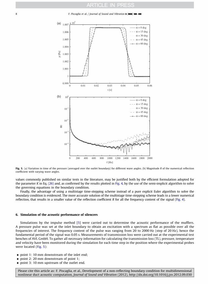
values commonly published on similar tests in the literature, may be justified both by the efficient formulation adopted for
the parameter K in Eq. (26) and, as confirmed by the results plotted in Fig. 4, by the use of the semi-implicit algorithm to solve
the governing equations in the boundary condition.
Finally, the advantage of using a multistage time-stepping scheme instead of a pure explicit Euler algorithm to solve the
boundary condition is evidenced. The more accurate solution of the multistage time-stepping scheme leads to a lower numerical
reflection, that results in a smaller value of the reflection coefficient R for all the frequency content of the signal (Fig. 4).
6. Simulation of the acoustic performance of silencers
Simulations by the impulse method [5] were carried out to determine the acoustic performance of the mufflers.
A pressure pulse was set at the inlet boundary to obtain an excitation with a spectrum as flat as possible over all the
frequencies of interest. The frequency content of the pulse was ranging from 20 to 2000 Hz (step of 20 Hz), hence the
fundamental period of the signal was 0.05 s. Measurements of transmission loss were carried out at the experimental test
benches of AVL GmbH. To gather all necessary information for calculating the transmission loss (TL), pressure, temperature
and velocity have been monitored during the simulation for each time step in the position where the experimental probes
were located (Fig. 5):
� point 1: 10 mm downstream of the inlet end;
� point 2: 20 mm downstream of point 1;
� point 3: 10 mm upstream of the outlet end.
0 0.01 0.02 0.03 0.04 0.05 0.060.999
1
1.001
1.002
1.003
1.004
1.005
1.006
1.007x 10
t [s]
p [
Pa]
α = 0 deg
α = 15 deg
α = 30 deg
α = 45 deg
α = 60 deg
0 200 400 600 800 1000 1200 1400 1600 1800 2000
10
10
10
10
10
f [Hz]
|R|
α = 0 deg
α = 15 deg
α = 30 deg
α = 45 deg
α = 60 deg
Fig. 3. (a) Variation in time of the pressure (averaged over the outlet boundary) for different wave angles. (b) Magnitude R of the numerical reflection
coefficient with varying wave angles.
Please cite this article as: F. Piscaglia, et al., Development of a non-reflecting boundary condition for multidimensionalnonlinear duct acoustic computation, Journal of Sound and Vibration (2012), http://dx.doi.org/10.1016/j.jsv.2012.09.030
F. Piscaglia et al. / Journal of Sound and Vibration ] (]]]]) ]]]–]]]8

The evaluation of the TL was performed by an in-house developed post-processing algorithm based on the two-sensor
method [4].
7. Case setup: flow solver and boundary conditions
The models described in this work were implemented as boundary conditions in an open-source CFD code [7] that
makes use of the finite volume discretisation to solve the systems of partial differential equations. In the acoustic
simulations, compressible Navier–Stokes equations have been solved by a pressure implicit with splitting of operators
(PISO) solver. A second-order semi-implicit Crank–Nicholson scheme has been chosen for temporal discretisation;
standard finite volume discretisation of Gaussian integration, which requires the interpolation of values from cell centers
to face centers, has been used for differential operators (gradient, Laplacian and divergence operator). The realizable k2Eturbulence model with wall functions was chosen for closure. The working fluid has been assumed to be air, and the
boundary conditions have been set as follows:
� inlet b.c.: pressure pulse with frequency content in the range between 20 and 2000 Hz (step 20 Hz);
� outlet b.c.: subsonic non-reflective NSCBC boundary condition (anechoic);
� walls have been modeled as adiabatic.
0 200 400 600 800 1000 1200 1400 1600 1800 2000
10
10
10
10
10
f [Hz]
|R|
n = 1
n = 50
Fig. 4. Magnitude of the reflection coefficient R for different numbers of sub-cycle iterations in the multistage time-stepping scheme. In the simulations,
the wave angle a is 301.
Silencer b [mm] d [mm] D [mm] e1 [mm] e2 [mm] L [mm] S [mm] x1 [mm] x12 [mm] x3 [mm]
RC-l1 17 50 197 17 17 494 50 10 20 10
RC-l2 17 50 197 257 17 494 50 10 20 10
RC-m 17 50 197 167 17 377 50 10 20 10
RC-s 17 50 197 17 17 127 50 10 20 10
Fig. 5. Geometric features of the silencer with flow reversal. Diameters reported are inner diameters, wall thickness is 1.5 mm. Geometric details and
experimental measurements are courtesy of AVL.
Please cite this article as: F. Piscaglia, et al., Development of a non-reflecting boundary condition for multidimensionalnonlinear duct acoustic computation, Journal of Sound and Vibration (2012), http://dx.doi.org/10.1016/j.jsv.2012.09.030
F. Piscaglia et al. / Journal of Sound and Vibration ] (]]]]) ]]]–]]] 9

The time step has been limited by the CFL criterion
ðuþcÞDt2Dx
r1 (29)
to ensure a maximum Courant number of 0.4. The maximum time-step resulted to be 10�6 s; this guarantees a sampling
frequency that is much higher than the frequency needed to satisfy the Nyquist sampling law. Simulation time has been
set as multiple of the period of the perturbation T ¼ 1=minðfmin,f stepÞ. In authors’ experience, at least two periods are
needed to reach full convergence in the simulation. In order to not affect the results by the noise due to non-periodic
effects occurring in the early time steps of the simulation, 10 periods were simulated (0.5 s) and a phase average over the
last eight was performed.
8. Results and discussion
In this study, two different muffler layouts were chosen for validation: the flow-reversing chamber and the single
plug muffler. The aim was to evaluate the behavior of the anechoic boundary condition developed when used with a
three-dimensional time-domain CFD approach to predict the acoustic performance of mufflers with and without mean
flow velocity of the gas.
8.1. Flow-reversing chambers
The flow-reversing chamber is a very well-known configuration of expansion chamber, where both inlet and outlet are
located on the same end-plate [19,20]. Extensions of inlet and outlet pipes within the chamber are meant to suppress the
pass-bands of the expansion chamber by means of resonance peaks typical of quarter wave resonators. The higher order
modes are excited at the area discontinuities of these silencers, and they do not decay fully before reaching the other
opening because of the close proximity of inlet and outlet. Hence, multidimensional wave propagation needs to be
Frequency [Hz]
0
10
20
30
40
50
Tra
nsm
issio
n loss [dB
]
RC-l1
Frequency [Hz]
0
10
20
30
40
50
Tra
nsm
issio
n loss [dB
]
RC-l2
Frequency [Hz]
0
10
20
30
40
50
Tra
nsm
issio
n loss [dB
]
RC-m
0 250 500 750 1000 1250 1500 1750 2000 0 250 500 750 1000 1250 1500 1750 2000
0 250 500 750 1000 1250 1500 1750 2000 0 250 500 750 1000 1250 1500 1750 2000
Frequency [Hz]
0
10
20
30
40
50
Tra
nsm
issio
n loss [dB
]
RC-s
Fig. 6. Transmission loss of the four reverse-chamber geometries. Legend: � Experimental (M¼0); — CFD (M¼0); - - - CFD (M¼0.15).
Please cite this article as: F. Piscaglia, et al., Development of a non-reflecting boundary condition for multidimensionalnonlinear duct acoustic computation, Journal of Sound and Vibration (2012), http://dx.doi.org/10.1016/j.jsv.2012.09.030
F. Piscaglia et al. / Journal of Sound and Vibration ] (]]]]) ]]]–]]]10

considered both in the chamber and in the end ducts for an accurate prediction of the acoustic attenuation performance
even at low frequencies. Four configurations, reported in Fig. 5, are considered in this section. The configuration named
‘‘RC-l1’’ is characterized by an overall length of 494 mm and the inlet pipe is 17 mm long; the ‘‘RC-l2’’ configuration
has still a chamber length of 494 mm, but the inlet duct has been extended to a total length of 257 mm; the ‘‘RC-m’’
(mid length) chamber and the ‘‘RC-s’’ (short) chamber are respectively 377 and 127 mm long, and their inlet ducts are 167
and 17 mm long. Experimental measurements of TL (Fig. 6) show a first abatement peak that can be interpreted as the
result of the interference between the quarter wave effect generated by the chamber length and the extension of the inlet
pipe within the chamber. The second peak is the third harmonic of this resonance frequency. The pass bands of the series
chamber are at multiples of the base frequency f 0 ¼ c=2L and are dependent on the length of the chamber. As shown in
Fig. 6, multidimensional simulation of the reversing chambers allows to satisfactorily capture the resonance peaks and the
transparency frequencies of the silencers in all the frequency range, with some exception. In particular, the discrepancy
between simulations and experiments for the short reversing chamber at 1250 Hz and 1500 Hz has been studied by
monitoring the acoustic pressure fields inside the mufflers. Figs. 7–10 show that as the spherical wave generated at the
inlet reaches the volume, a transverse propagation pattern, that becomes more apparent for shorter lengths of the
chamber, develops. At some frequencies, the transverse component of non-planar waves near the outlet is present
(Fig. 10); in these cases the base-assumption of one-dimensional planar wave propagation in the inlet and outlet pipes,
required by the post-processing algorithm, is not valid any longer and the calculation of the transmission loss becomes less
accurate. For the same four configurations, the calculated transmission loss for a mean flow Mach number M¼0.15 is
provided; as expected, mean flow shifts the transmission loss curve because of the convective effect, in particular at high
frequency.
8.2. Single plug muffler
Satisfying results were obtained by the proposed approach also for the single-plug perforated silencer, whose features
are reported in Fig. 11. In this case, the CFD simulation is able to capture the transparency frequency at 825 Hz due to the
main longitudinal resonance, that might be also estimated by f0¼a/2L (where L is the length of the chamber). At high
frequency there is some noise in the measurements, but they are still reliable for validation. In Fig. 11 the influence of the
mean flow on the transmission loss for the same silencer is also shown. As expected, the mean flow causes an increase of
the acoustic attenuation in the medium-low frequency range (0–1200 Hz), where measurements were available. The mean
flow shifts the transmission loss curve because of the convective effect; part of the sound energy is converted into heat due
to the dissipative effect in the holes, that acts as a resistive impedance.
Fig. 7. Acoustic field inside the reverse chamber ‘‘RC-l1’’ calculated by the CFD method (M¼0). Calculations were performed on a mesh having about 590
thousand cells.
Please cite this article as: F. Piscaglia, et al., Development of a non-reflecting boundary condition for multidimensionalnonlinear duct acoustic computation, Journal of Sound and Vibration (2012), http://dx.doi.org/10.1016/j.jsv.2012.09.030
F. Piscaglia et al. / Journal of Sound and Vibration ] (]]]]) ]]]–]]] 11

9. Conclusions
Accurate predictions of the acoustic performance of silencers have been carried out by the implementation of a novel
boundary condition based on the characteristic theory combined with the linear relaxation method. The original
formulation of the NSCBC framework [9] has been extended to local coordinates and the system of governing equations
has been solved by an effective multistage semi-implicit time stepping scheme, that is more stable and accurate than a
traditional explicit method and allows for larger global time steps in the simulation. A formulation of the reflected
characteristic in generalized coordinates, to compute the actual reflection coefficient for numerical non-reflecting
boundary conditions by the linear relaxation method, has been included in the implementation of a non-reflecting
Fig. 8. Acoustic field inside the reverse chamber ‘‘RC-l2’’ calculated by the CFD method (M¼0). Calculations were performed on a mesh having about 530
thousand cells.
Fig. 9. Acoustic field inside the reverse chamber ‘‘RC-m’’ calculated by the CFD method (M¼0). Calculations were performed on a mesh having about 490
thousand cells.
Please cite this article as: F. Piscaglia, et al., Development of a non-reflecting boundary condition for multidimensionalnonlinear duct acoustic computation, Journal of Sound and Vibration (2012), http://dx.doi.org/10.1016/j.jsv.2012.09.030
F. Piscaglia et al. / Journal of Sound and Vibration ] (]]]]) ]]]–]]]12

boundary condition. The resulting boundary condition gives very small reflections even for high wave angles of the
incident pressure wave, so it is suitable for the multidimensional nonlinear simulation of silencers. The computational
effort of the proposed approach looks high if compared to the effort required by solvers based on the multidimensional
approach in the frequency domain, where linearization of the NS equations in the inner domain is performed. On the other
hand, complex flow and viscous effects are considered, so the effects of the mean flow on the acoustic attenuation
performance of silencers with complex geometries may be successfully captured. No calibration constants have been used
in the simulations, so this approach may be considered as fully predictive.
Acknowledgments
Authors would like to acknowledge AVL List GmbH (Graz, Austria) for the experimental measurements provided to
validate the model. Computational resources were provided by CINECA (Bologna, Italy) through the Italian Super-
Computing Resource Allocation (ISCRA) framework, Project LES4ICE. We greatly appreciated the valuable suggestions of
two anonymous referees and of the scientific editor, which helped to improve the manuscript substantially.
Fig. 10. Acoustic field inside the reverse chamber ‘‘RC-short’’ calculated by the CFD method (M¼0). Calculations were performed on a mesh having about
420 thousand cells.
12008004000
Frequency [Hz]
0
10
20
30
40
Tra
nsm
issio
n lo
ss [
dB
]
single plug perforated
Silencer d [mm] D [mm] la [mm] lp [mm] tw [mm] dh [mm] porosity [%]
P1 57 197 95 15 2 5 5
Fig. 11. (a) Geometric features of the single-plug perforated silencer. (b) Transmission loss of the single-plug perforated silencer with zero (M¼0) and
non-zero mean flow velocity of the gas (M¼0.05): comparison between simulations and experiments. Experimental measurements are courtesy of AVL.
Please cite this article as: F. Piscaglia, et al., Development of a non-reflecting boundary condition for multidimensionalnonlinear duct acoustic computation, Journal of Sound and Vibration (2012), http://dx.doi.org/10.1016/j.jsv.2012.09.030
F. Piscaglia et al. / Journal of Sound and Vibration ] (]]]]) ]]]–]]] 13

References
[1] T. Tsuji, T. Tsuchiya, Y. Kagawa, Finite element and boundary element modelling for the acoustic wave transmission in mean flowmedium, Journal ofSound and Vibration 255 (5) (2002) 849–866.
[2] A. Broatch, X. Margot, A. Gil, F.D. Denia, A cfd approach to the computation of the acoustic response of exhaust mufflers, Journal of Computational
Acoustics 13 (2) (2005) 301–316.[3] Z.L. Ji, H.S. Xu, Z.X. Kang, Influence of mean flow on acoustic attenuation performance of straight-through perforated tube reactive silencers and
resonators, Noise Control Engineering Journal 58 (1) (2010) 12–17.[4] A.F. Seybert, Two-sensor methods for the measurement of sound intensity and acoustic properties in ducts, Journal of Acoustic Society of America 82
(6) (1988) 2233–2239.[5] G. Montenegro, A. Onorati, A. Della Torre, A. Torregrosa, The 3dcell approach for the acoustic modeling of after-treatment devices, SAE International
Journal of Engines 4 (2) (2011) 2519–2530.[6] G. Montenegro, A. Onorati, A coupled 1d-multid nonlinear simulation of i.c. engine silencers with perforates and sound-absorbing material,
SAE International Journal of Passenger Cars—Mechanical Systems 2 (1) (2010) 482–494.[7] OpenCFD Ltd., OpenFOAMs Programmer’s Guide, 2004.[8] T.J. Poinsot, S.K. Lele, Boundary conditions for direct simulations of compressible viscous flows, Journal of Computational Physics 101 (1) (1992)
104–129.[9] T. Poinsot, D. Veynante, Theoretical and Numerical Combustion, Edwards, R.T., Philadelphia, PA, USA, 2005.
[10] K.W. Thompson, Time dependent boundary conditions for hyperbolic systems, Journal of Computational Physics 68 (1) (1987) 1–24.[11] D.H. Rudy, J.C. Strikwerda, A nonreflecting outflow boundary condition for subsonic Navier–Stokes calculations, Journal of Computational Physics 36
(1) (1980) 55–70.[12] J.B. Keller, D. Givoli, Exact non-reflecting boundary conditions, Journal of Computational Physics 82 (1) (1989) 172–192.[13] T. Hagstrom, S.I. Hariharan, Accurate boundary conditions for exterior problems in gas dynamics, Mathematics of Computation 51 (1988) 581–597.[14] R. Vichnevetsky, Invariance theorems concerning reflection at numerical boundaries, Journal of Computational Physics 63 (2) (1986) 268–282.[15] X. Chen, G.-C. Zha, Implicit application of non-reflective boundary conditions for navier-stokes equations in generalized coordinates, International
Journal for Numerical Methods in Fluids 50 (2006) 767–793.[16] S.K. Lele, Direct numerical simulation of compressible free shear flows, in: 27th Aerospace Sciences Meeting, AIAA-89-0374, Reno Nevada, 1989.[17] S.K. Richards, X. Zhang, X.X. Chen, P.A. Nelson, The evaluation of non-reflecting boundary conditions for duct acoustic computation, Journal of Sound
and Vibration 270 (3) (2004) 539–557. (2002 I.M.A. Conference on Computational Aeroacoustics).[18] Q. Liu, O.V. Vasilyev, Nonreflecting boundary conditions based on nonlinear multidimensional characteristics, International Journal for Numerical
Methods in Fluids 62 (1) (2010) 24–55.[19] A. Selamet, Z.L. Ji, Acoustic attenuation performance of circular flow-reversing chambers, The Journal of the Acoustical Society of America 104 (5)
(1998) 2867–2877.[20] A. Selamet, Z. Ji, P. Radavich, Acoustic attenuation performance of circular expansion chambers with offset inlet/outlet: II. Comparison with
experimental and computational studies, Journal of Sound and Vibration 213 (4) (1998) 619–641.
Please cite this article as: F. Piscaglia, et al., Development of a non-reflecting boundary condition for multidimensionalnonlinear duct acoustic computation, Journal of Sound and Vibration (2012), http://dx.doi.org/10.1016/j.jsv.2012.09.030
F. Piscaglia et al. / Journal of Sound and Vibration ] (]]]]) ]]]–]]]14