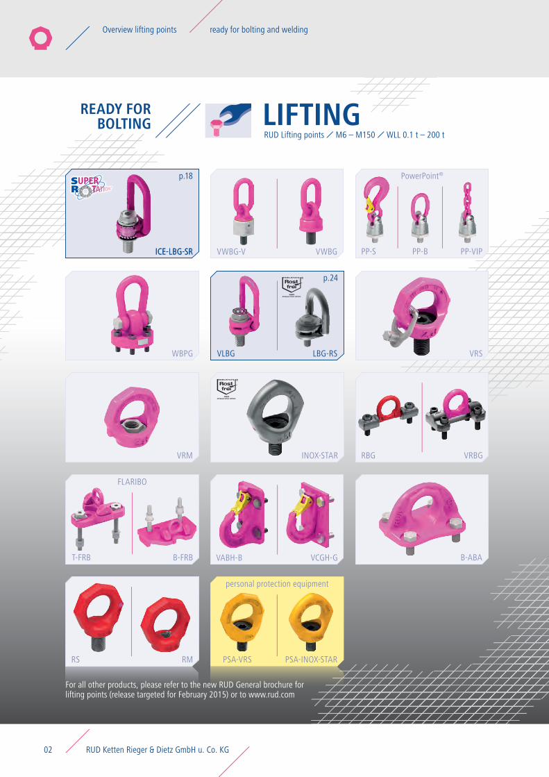
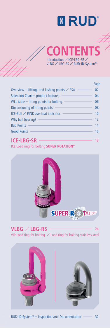
ICE-LBG-SR VLBG · p.18 ICE-LBG-SR WBPG VRS VRM INOX-STAR VLBG LBG-RS T-FRB B-FRB FLARIBO RBG VRBG...
38
Edition 02 EN VLBG ICE-LBG-SR
Transcript of ICE-LBG-SR VLBG · p.18 ICE-LBG-SR WBPG VRS VRM INOX-STAR VLBG LBG-RS T-FRB B-FRB FLARIBO RBG VRBG...
Edition 02 EN
VLBGICE-LBG-SR
p.18
ICE-LBG-SR
WBPG VRS
VRM INOX-STAR
LBG-RSVLBG
B-FRBT-FRB
FLARIBO
VRBGRBG
PSA-INOX-STARPSA-VRS
p.24
ICE-LBG-SR VWBGVWBG-V
B-ABA
RMRS
VABH-B VCGH-G
personal protection equipment
PP-B PP-VIPPP-S
PowerPoint®
LIFTINGREADY FORBOLTING
RUD Lifting points M6 – M150 WLL 0.1 t – 200 t
For all other products, please refer to the new RUD General brochure for lifting points (release targeted for February 2015) or to www.rud.com
RUD Ketten Rieger & Dietz GmbH u. Co. KG02
Overview lifting points ready for bolting and welding
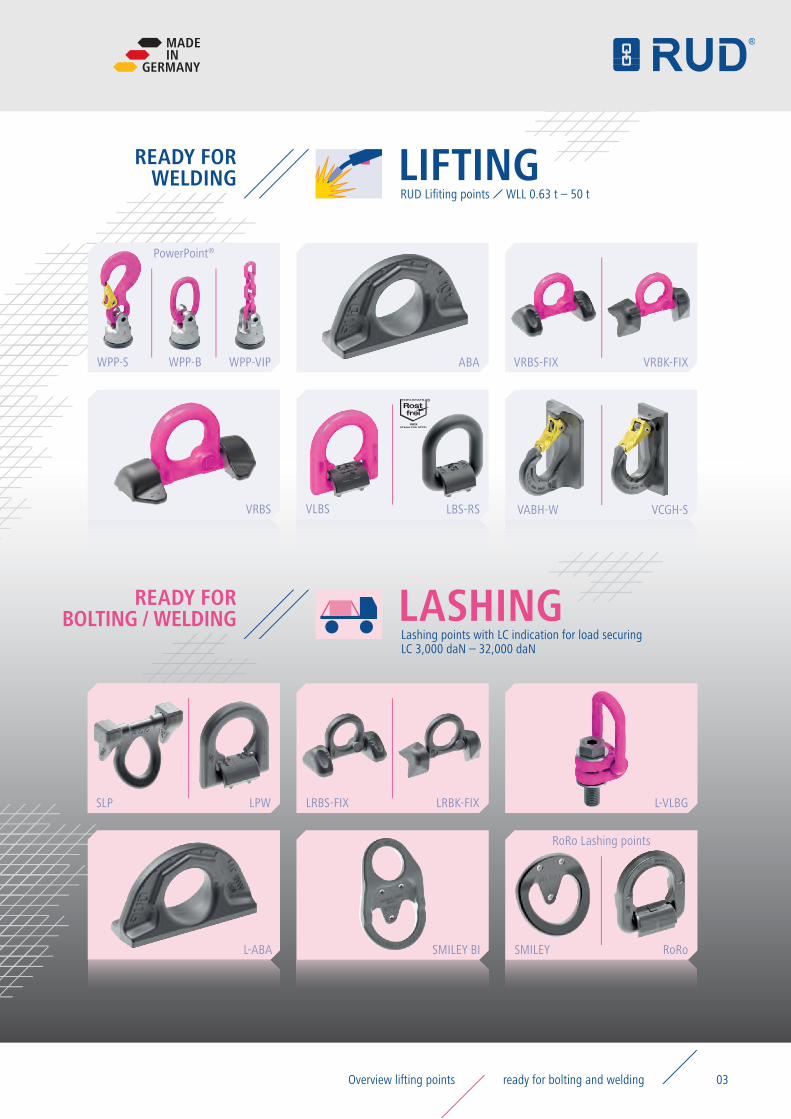
READY FOR BOLTING / WELDING
READY FORWELDING LIFTING
RUD Lifiting points WLL 0.63 t – 50 t
LASHINGLashing points with LC indication for load securing LC 3,000 daN – 32,000 daN
LPWSLP
SMILEY BI
LRBS-FIX LRBK-FIX
WPP-S WPP-B WPP-VIP
L-ABA
L-VLBG
PowerPoint®
RoRoSMILEY
VRBS LBS-RS
ABA
VLBS
VRBS-FIX
VABH-W
VRBK-FIX
VCGH-S
RoRo Lashing points
MADEIN
GERMANY
03ready for bolting and weldingOverview lifting points
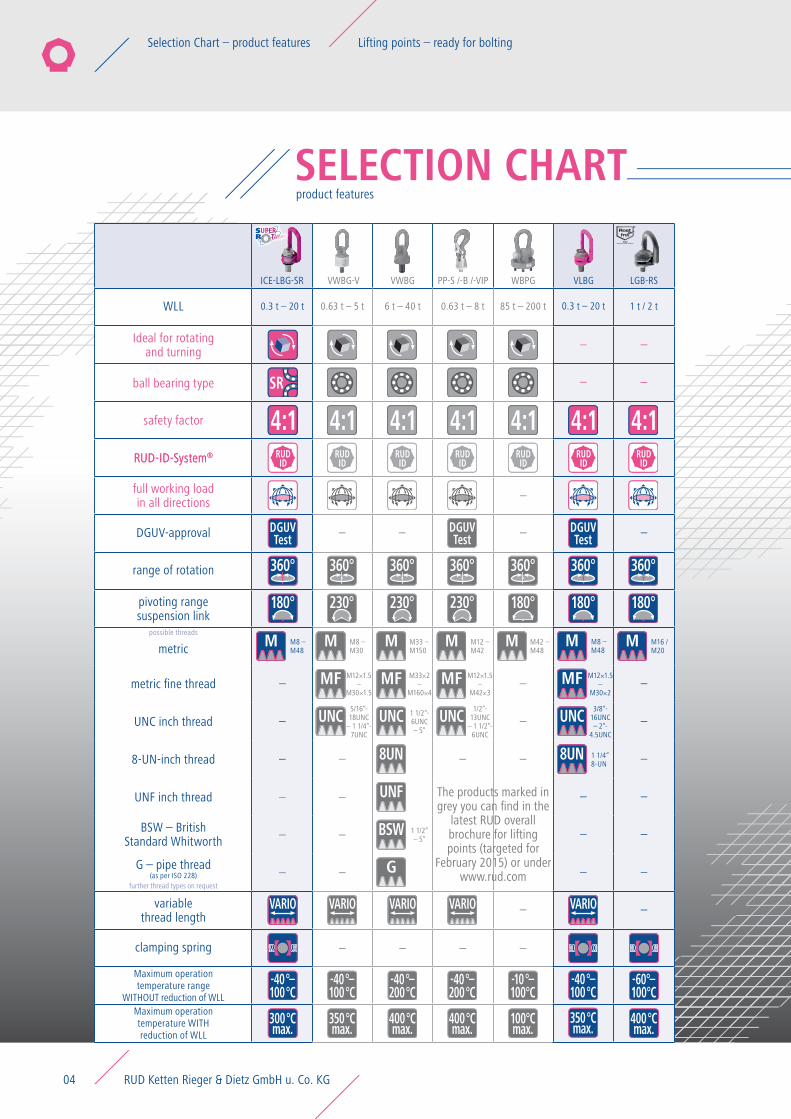
ICE-LBG-SR VWBG-V VWBG PP-S /-B /-VIP WBPG VLBG LGB-RS VRS VRM INOX-STAR RBG / VRBG FLARIBO VABH-B VCGH-G B-ABA RS RM
UNF
8UN
350°Cmax.
-40°–100°C
M8 – M30
M12×1.5–
M30×1.5
M33 – M150
5/16“-18UNC
– 1 1/4“-7UNC
UNC UNC
MF MF
M M
M33×2–
M160×4
1 1/2“-6UNC – 5“
180°230° 230° 230° 180° 180°
360° 360° 360° 360° 360° 360° 360°
180°
SR
0.3 t – 20 t0.3 t – 20 t
M8 – M48
M8 – M48
M16 / M20
3/8“-16UNC– 2“-
4.5UNC
1 1/2“ – 5“
1 t / 2 t0.63 t – 5 t 6 t – 40 t 0.63 t – 8 t 85 t – 200 t
–
–
–
–
–
–
–
–
–
–
– –
– –
–
– –
–
–
– –
–
–
–
–
––
––
–
–
––
–
–
M
MF
UNC
8UN
G
BSW
M
400°Cmax.
400°Cmax.
400°Cmax.
350°Cmax.
-40°–100°C
-60°–100°C
-10°–100°C
100°Cmax.
-40°–200°C
-40°–200°C
M
–
–
M
300°Cmax.
-40°–100°C
RUDID
RUDID
RUDID
RUDID
RUDID
RUDID
RUDID
4:14:1 4:14:14:14:1 4:14:1 4:1 4:14:14:1
DGUVTest
DGUVTest
DGUVTest
M12 – M42
1/2”-13UNC
– 1 1/2”-6UNC
UNC
MF
M
M12×1.5–
M42×3
M12×1.5–
M30×2
–
1 1/4“8-UN
VARIOVARIOVARIO VARIO VARIO
The products marked in grey you can find in the
latest RUD overall brochure for lifting points (targeted for
February 2015) or under www.rud.com
WLL
range of rotation
DGUV-approval
possible threads
further thread types on request
metric
metric fine thread
UNC inch thread
8-UN-inch thread
UNF inch thread
clamping spring
BSW – British Standard Whitworth
G – pipe thread(as per ISO 228)
pivoting range suspension link
RUD-ID-System®RUD-ID-System®
safety factor
ball bearing type
full working load in all directions
Maximum operation temperature range
WITHOUT reduction of WLLMaximum operation temperature WITH reduction of WLL
SELECTION CHARTproduct features
Ideal for rotating and turning
variable thread length
M42 – M48
RUD Ketten Rieger & Dietz GmbH u. Co. KG04
Selection Chart – product features Lifting points – ready for bolting
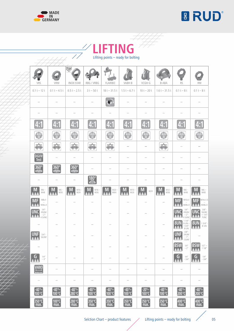
ICE-LBG-SR VWBG-V VWBG PP-S /-B /-VIP WBPG VLBG LGB-RS VRS VRM INOX-STAR RBG / VRBG FLARIBO VABH-B VCGH-G B-ABA RS RM
–
180°
360° 360° 360°
3/4“-16UNF
1 3/4“-8-UN
M6 – M48
M6 – M48
M6 – M48
M16 – M24
M16 – M36
M10 – M20 M24
M8×1–
M36×3
M10×1–
M48×3
M14×1.5–
M48×3
M6 – M30
1/4“-20UNC – 2”-
4.5UNC
1/4“-20UNC – 2”-
4.5UNC
3/8“-16UNC
– 1 1/4”-7UNC
3/8“-24UNF – 1”-
12UNF
1/4“ – 2“
1/4“ – 3/4“
1/4“ – 3/4“
1/4“ – 3“
1/2“ – 1 1/8“
0.1 t – 12 t 0.1 t – 4.5 t 0.1 t – 8 t 0.1 t – 8 t0.5 t – 2.5 t 3 t – 50 t 18 t – 31.5 t 1.5 t – 6.7 t 10 t – 20 t
–
–
–
–
–
–
–
–
–
–
–
–
–
–
–
–
–
–
–
–
–
–
–
–
–
–
–
–
–
–
–
–
– –
–
–
–
–
–
–
–
– –
–
–
–
– –
–
–
–
–
–
–
–
–
– –
–
–
–
– –
–
–
–
–
–
–
––
–
–
–
–
–
–
–
–
– ––
–
–
–
–
–
–
––
–
–
–
–
–
8UN
UNF
G G G
UNF
BSW BSW
8UN
UNC UNC UNC
MF MF MF
M M M M
400°Cmax.
400°Cmax.
280°Cmax.
-40°–100°C
350°Cmax.
350°Cmax.
350°Cmax.
350°Cmax.
350°Cmax.
350°Cmax.
-40°–100°C
-40°–100°C
-40°–100°C
-40°–100°C
-20°–100°C
-40°–100°C
100°Cmax.
-40°–200°C
-40°–280°C
-40°–200°C
M M M M M M
–
–
–
–
–
–
–
–
–
–
–
–
RUDID
RUDID
RUDID
RUDID
RUDID
RUDID
RUDID
RUDID
RUDID
RUDID
4:1 4:14:1 4:1 4:14:1 4:1 4:14:1 4:1
–– –– – ––
DGUVTest
M20 – M64
1 1/4“-8-UN – 1 3/4”-8-UN
M12 – M36
VARIO
LIFTINGLifiting points – ready for bolting
1.6 t – 31.5 t
MADEIN
GERMANY
05Selction Chart – product features Lifting points – ready for bolting
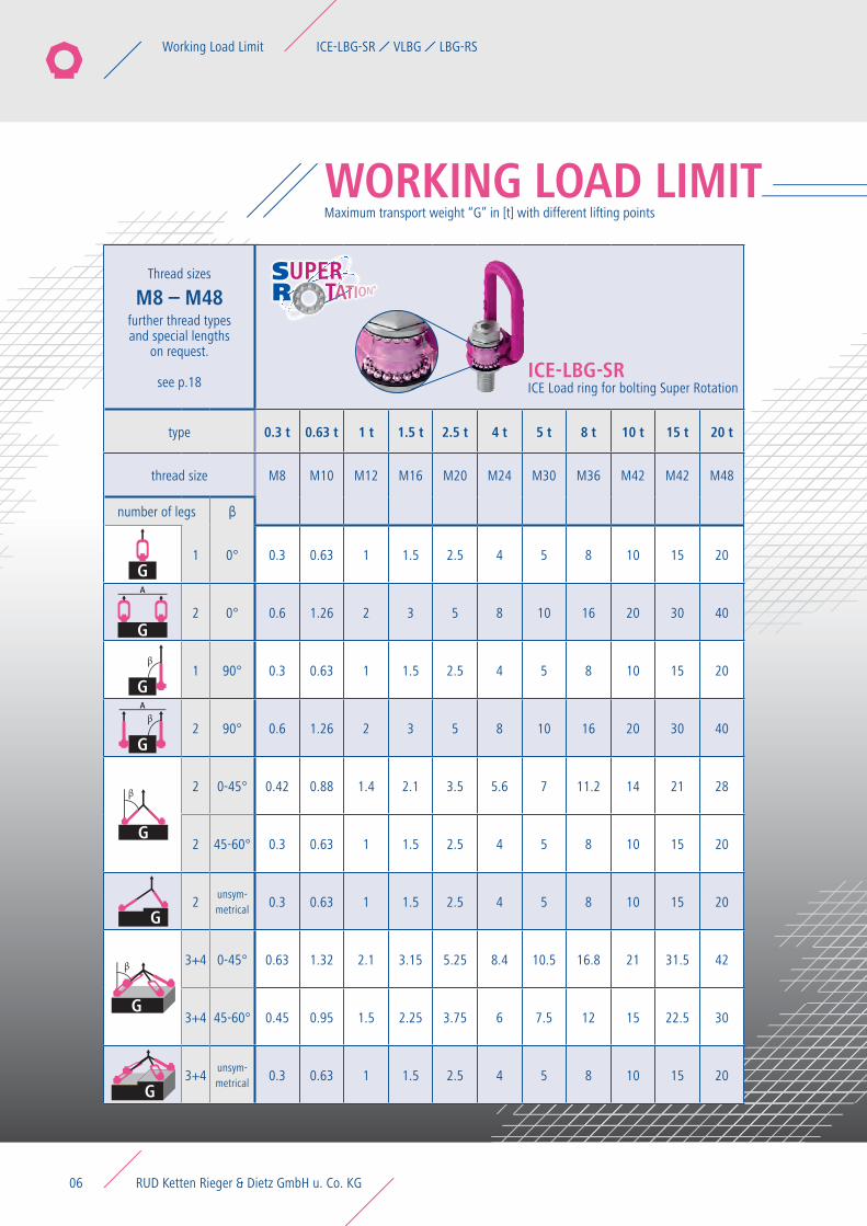
Thread sizes
M8 – M48further thread typesand special lengths
on request.
see p.18
Thread sizes
M8 – M48further thread typesand special lengths
on request.
see p.24
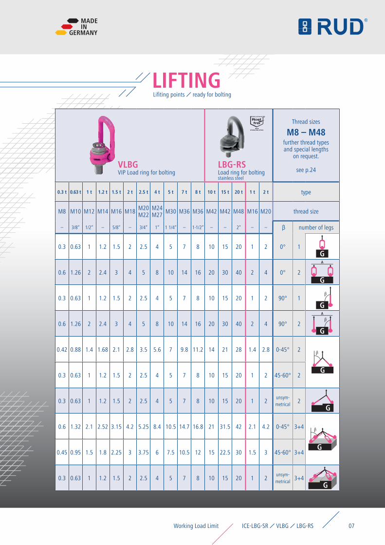
type 0.3 t 0.63 t 1 t 1.5 t 2.5 t 4 t 5 t 8 t 10 t 15 t 20 t 0.3 t 0.63 t 1 t 1.2 t 1.5 t 2 t 2.5 t 4 t 5 t 7 t 8 t 10 t 15 t 20 t 1 t 2 t type
thread size M8 M10 M12 M16 M20 M24 M30 M36 M42 M42 M48 M8 M10 M12 M14 M16 M18 M20M22
M24M27 M30 M36 M36 M42 M42 M48 M16 M20 thread size
number of legs β – 3/8“ 1/2“ – 5/8“ – 3/4“ 1“ 1 1/4“ – 1-1/2“ – – 2“ – – β number of legs
1 0° 0.3 0.63 1 1.5 2.5 4 5 8 10 15 20 0.3 0.63 1 1.2 1.5 2 2.5 4 5 7 8 10 15 20 1 2 0° 1
2 0° 0.6 1.26 2 3 5 8 10 16 20 30 40 0.6 1.26 2 2.4 3 4 5 8 10 14 16 20 30 40 2 4 0° 2
1 90° 0.3 0.63 1 1.5 2.5 4 5 8 10 15 20 0.3 0.63 1 1.2 1.5 2 2.5 4 5 7 8 10 15 20 1 2 90° 1
2 90° 0.6 1.26 2 3 5 8 10 16 20 30 40 0.6 1.26 2 2.4 3 4 5 8 10 14 16 20 30 40 2 4 90° 2
2 0-45° 0.42 0.88 1.4 2.1 3.5 5.6 7 11.2 14 21 28 0.42 0.88 1.4 1.68 2.1 2.8 3.5 5.6 7 9.8 11.2 14 21 28 1.4 2.8 0-45° 2
2 45-60° 0.3 0.63 1 1.5 2.5 4 5 8 10 15 20 0.3 0.63 1 1.2 1.5 2 2.5 4 5 7 8 10 15 20 1 2 45-60° 2
2unsym-metrical
0.3 0.63 1 1.5 2.5 4 5 8 10 15 20 0.3 0.63 1 1.2 1.5 2 2.5 4 5 7 8 10 15 20 1 2unsym-metrical
2
3+4 0-45° 0.63 1.32 2.1 3.15 5.25 8.4 10.5 16.8 21 31.5 42 0.6 1.32 2.1 2.52 3.15 4.2 5.25 8.4 10.5 14.7 16.8 21 31.5 42 2.1 4.2 0-45° 3+4
3+4 45-60° 0.45 0.95 1.5 2.25 3.75 6 7.5 12 15 22.5 30 0.45 0.95 1.5 1.8 2.25 3 3.75 6 7.5 10.5 12 15 22.5 30 1.5 3 45-60° 3+4
3+4unsym-metrical
0.3 0.63 1 1.5 2.5 4 5 8 10 15 20 0.3 0.63 1 1.2 1.5 2 2.5 4 5 7 8 10 15 20 1 2unsym-metrical
3+4
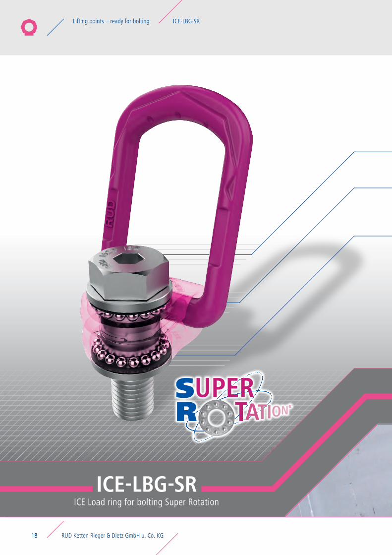
ICE-LBG-SR ICE Load ring for bolting Super Rotation
WORKING LOAD LIMITMaximum transport weight “G” in [t] with different lifting points
G
G
G
G
G
G
G
G
RUD Ketten Rieger & Dietz GmbH u. Co. KG06
Working Load Limit ICE-LBG-SR VLBG LBG-RS
Thread sizes
M8 – M48further thread typesand special lengths
on request.
see p.18
Thread sizes
M8 – M48further thread typesand special lengths
on request.
see p.24
type 0.3 t 0.63 t 1 t 1.5 t 2.5 t 4 t 5 t 8 t 10 t 15 t 20 t 0.3 t 0.63 t 1 t 1.2 t 1.5 t 2 t 2.5 t 4 t 5 t 7 t 8 t 10 t 15 t 20 t 1 t 2 t type
thread size M8 M10 M12 M16 M20 M24 M30 M36 M42 M42 M48 M8 M10 M12 M14 M16 M18 M20M22
M24M27 M30 M36 M36 M42 M42 M48 M16 M20 thread size
number of legs β – 3/8“ 1/2“ – 5/8“ – 3/4“ 1“ 1 1/4“ – 1-1/2“ – – 2“ – – β number of legs
1 0° 0.3 0.63 1 1.5 2.5 4 5 8 10 15 20 0.3 0.63 1 1.2 1.5 2 2.5 4 5 7 8 10 15 20 1 2 0° 1
2 0° 0.6 1.26 2 3 5 8 10 16 20 30 40 0.6 1.26 2 2.4 3 4 5 8 10 14 16 20 30 40 2 4 0° 2
1 90° 0.3 0.63 1 1.5 2.5 4 5 8 10 15 20 0.3 0.63 1 1.2 1.5 2 2.5 4 5 7 8 10 15 20 1 2 90° 1
2 90° 0.6 1.26 2 3 5 8 10 16 20 30 40 0.6 1.26 2 2.4 3 4 5 8 10 14 16 20 30 40 2 4 90° 2
2 0-45° 0.42 0.88 1.4 2.1 3.5 5.6 7 11.2 14 21 28 0.42 0.88 1.4 1.68 2.1 2.8 3.5 5.6 7 9.8 11.2 14 21 28 1.4 2.8 0-45° 2
2 45-60° 0.3 0.63 1 1.5 2.5 4 5 8 10 15 20 0.3 0.63 1 1.2 1.5 2 2.5 4 5 7 8 10 15 20 1 2 45-60° 2
2unsym-metrical
0.3 0.63 1 1.5 2.5 4 5 8 10 15 20 0.3 0.63 1 1.2 1.5 2 2.5 4 5 7 8 10 15 20 1 2unsym-metrical
2
3+4 0-45° 0.63 1.32 2.1 3.15 5.25 8.4 10.5 16.8 21 31.5 42 0.6 1.32 2.1 2.52 3.15 4.2 5.25 8.4 10.5 14.7 16.8 21 31.5 42 2.1 4.2 0-45° 3+4
3+4 45-60° 0.45 0.95 1.5 2.25 3.75 6 7.5 12 15 22.5 30 0.45 0.95 1.5 1.8 2.25 3 3.75 6 7.5 10.5 12 15 22.5 30 1.5 3 45-60° 3+4
3+4unsym-metrical
0.3 0.63 1 1.5 2.5 4 5 8 10 15 20 0.3 0.63 1 1.2 1.5 2 2.5 4 5 7 8 10 15 20 1 2unsym-metrical
3+4
LBG-RSLoad ring for bolting stainless steel
Lifiting points ready for boltingLIFTING
G
G
G
G
G
G
G
G
VLBGVIP Load ring for bolting
MADEIN
GERMANY
07Working Load Limit ICE-LBG-SR VLBG LBG-RS
Important facts for the designerDIMENSIONING
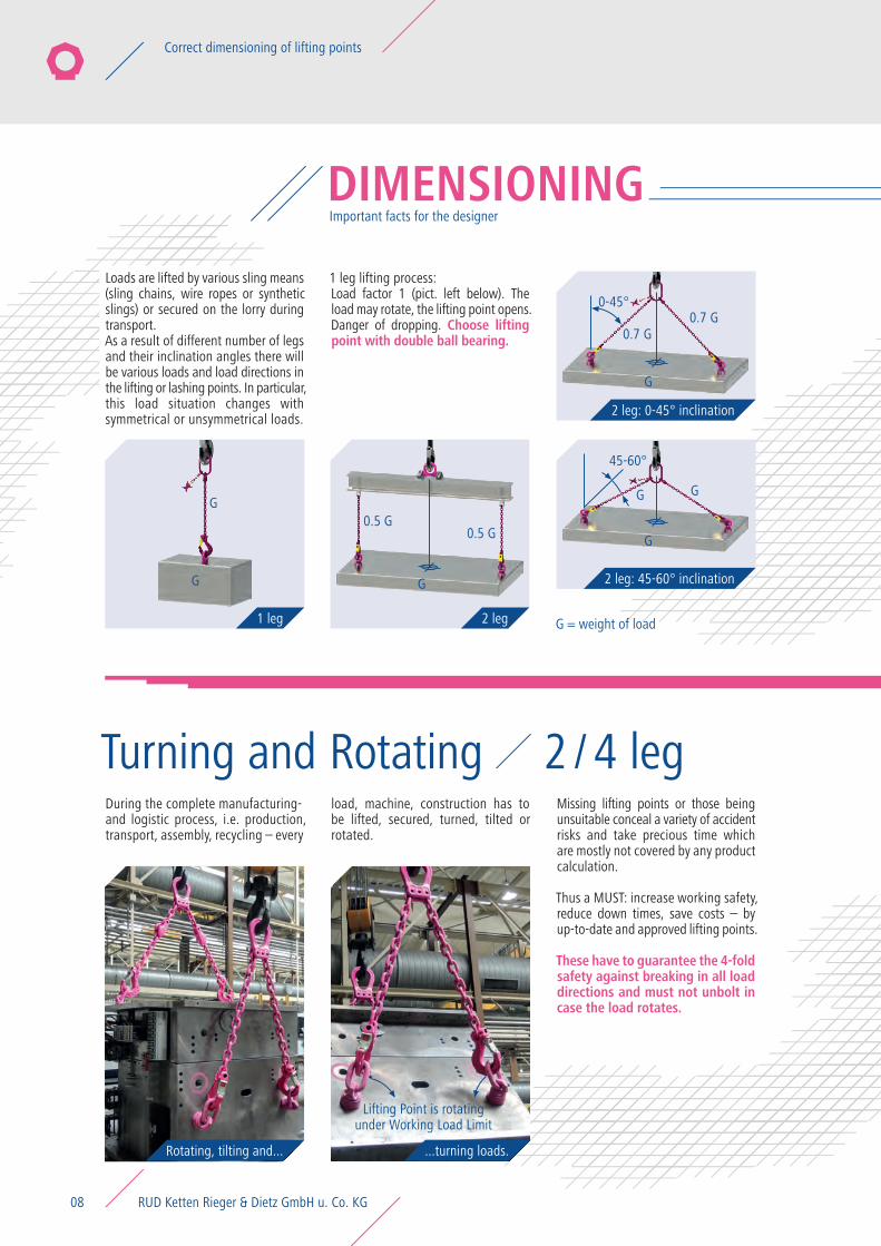
2 leg1 leg
2 leg: 45-60° inclination
2 leg: 0-45° inclination
Rotating, tilting and... ...turning loads.
G = weight of load
Turning and Rotating 2 / 4 leg
Loads are lifted by various sling means (sling chains, wire ropes or synthetic slings) or secured on the lorry during transport.As a result of different number of legs and their inclination angles there will be various loads and load directions in the lifting or lashing points. In particular, this load situation changes with symmetrical or unsymmetrical loads.
1 leg lifting process:Load factor 1 (pict. left below). The load may rotate, the lifting point opens. Danger of dropping. Choose lifting point with double ball bearing.
During the complete manufacturing-and logistic process, i.e. production, transport, assembly, recycling – every
load, machine, construction has to be lifted, secured, turned, tilted or rotated.
Missing lifting points or those being unsuitable conceal a variety of accident risks and take precious time which are mostly not covered by any product calculation.
Thus a MUST: increase working safety, reduce down times, save costs – by up-to-date and approved lifting points.
These have to guarantee the 4-fold safety against breaking in all load directions and must not unbolt in case the load rotates.
G0.5 G
0.7 G0.7 G
0-45°
Lifting Point is rotatingunder Working Load Limit
45-60°
GG
0.5 G
G G
G
G
RUD Ketten Rieger & Dietz GmbH u. Co. KG08
Correct dimensioning of lifting points
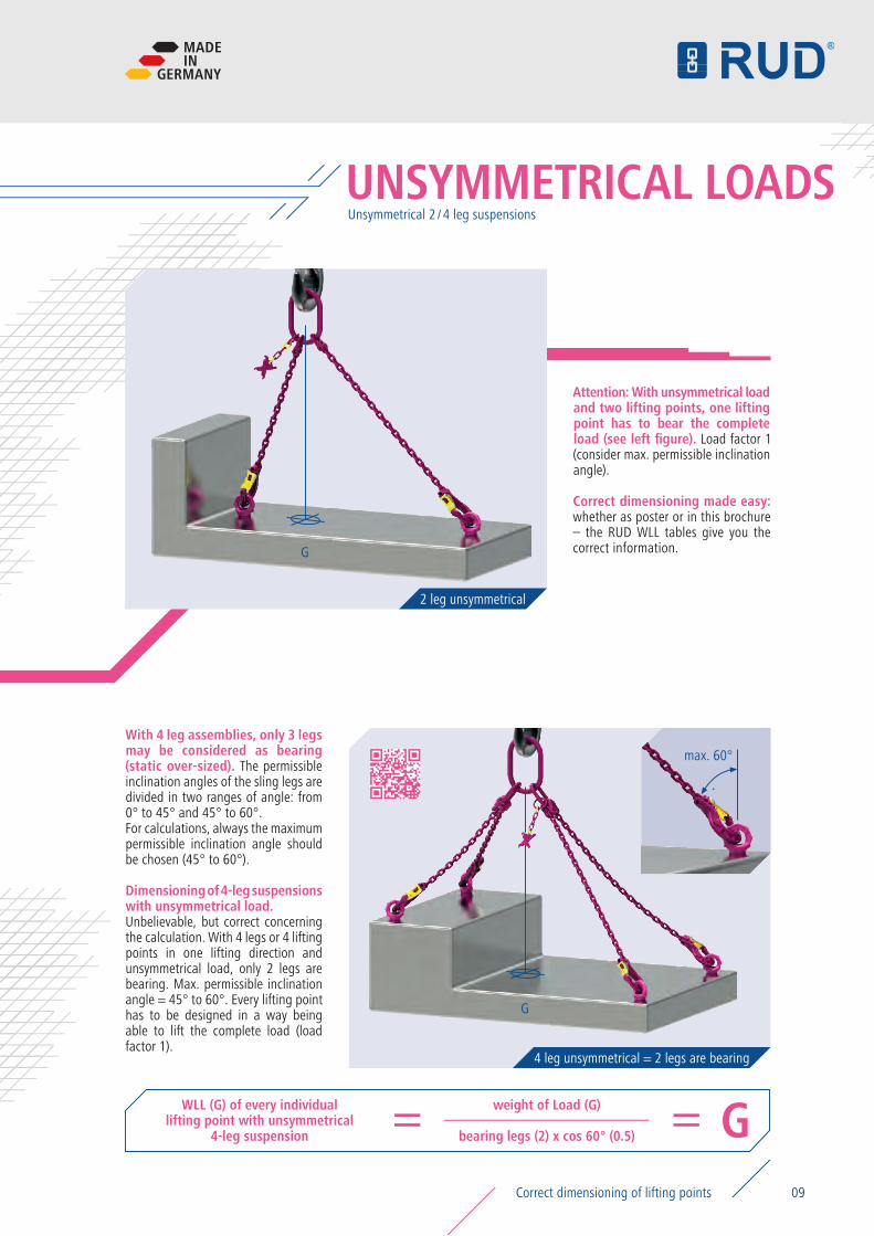
4 leg unsymmetrical = 2 legs are bearing
UNSYMMETRICAL LOADS
2 leg unsymmetrical
WLL (G) of every individual lifting point with unsymmetrical
4-leg suspension
weight of Load (G) G= =bearing legs (2) x cos 60° (0.5)
Unsymmetrical 2 / 4 leg suspensions
Attention: With unsymmetrical load and two lifting points, one lifting point has to bear the complete load (see left figure). Load factor 1 (consider max. permissible inclination angle).
Correct dimensioning made easy: whether as poster or in this brochure – the RUD WLL tables give you the correct information.
With 4 leg assemblies, only 3 legs may be considered as bearing (static over-sized). The permissible inclination angles of the sling legs are divided in two ranges of angle: from 0° to 45° and 45° to 60°. For calculations, always the maximum permissible inclination angle should be chosen (45° to 60°).
Dimensioning of 4-leg suspensions with unsymmetrical load. Unbelievable, but correct concerning the calculation. With 4 legs or 4 lifting points in one lifting direction and unsymmetrical load, only 2 legs are bearing. Max. permissible inclination angle = 45° to 60°. Every lifting point has to be designed in a way being able to lift the complete load (load factor 1).
max. 60°
G
G
MADEIN
GERMANY
09Correct dimensioning of lifting points
A CLASS OF ITS OWN
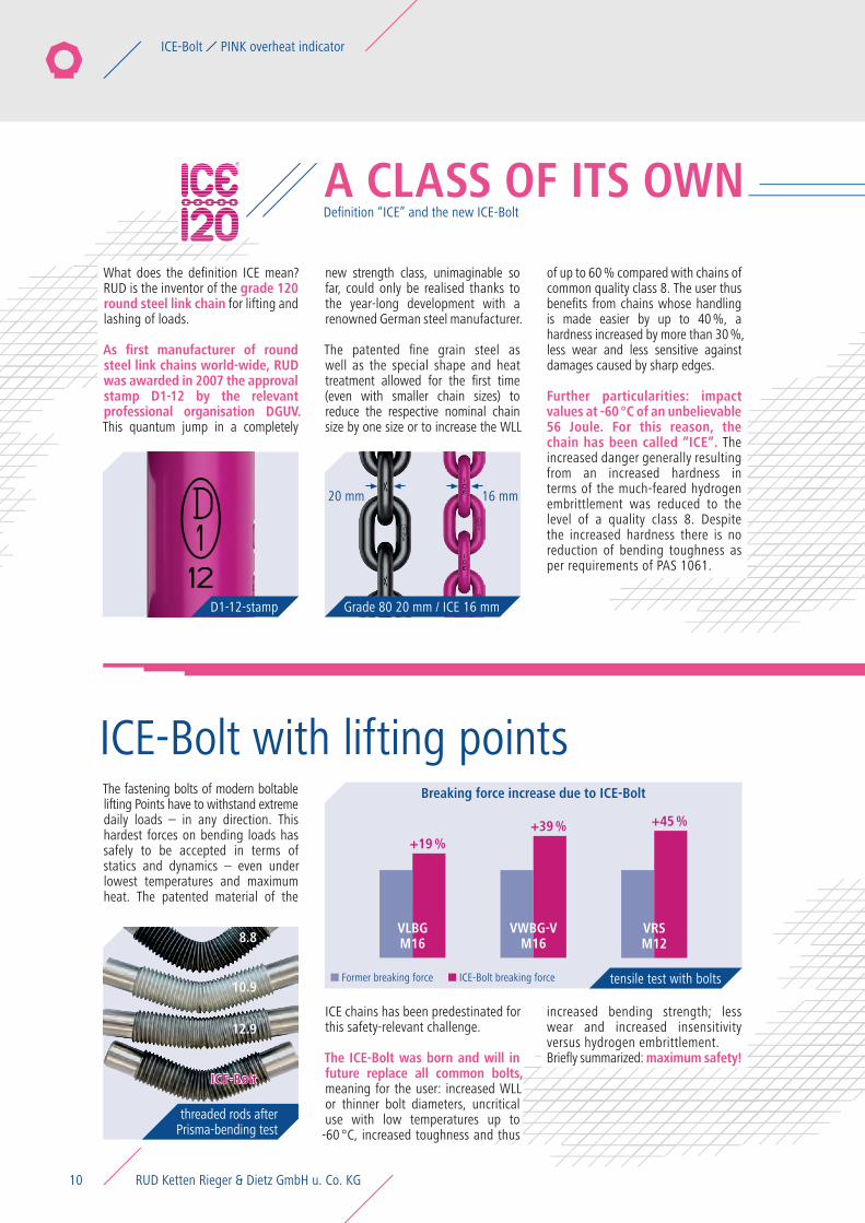
Grade 80 20 mm / ICE 16 mm D1-12-stamp
ICE-Bolt with lifting points8.8
threaded rods after Prisma-bending test
tensile test with bolts
Definition “ICE” and the new ICE-Bolt
What does the definition ICE mean? RUD is the inventor of the grade 120 round steel link chain for lifting and lashing of loads.
As first manufacturer of round steel link chains world-wide, RUD was awarded in 2007 the approval stamp D1-12 by the relevant professional organisation DGUV. This quantum jump in a completely
new strength class, unimaginable so far, could only be realised thanks to the year-long development with a renowned German steel manufacturer.
The patented fine grain steel as well as the special shape and heat treatment allowed for the first time (even with smaller chain sizes) to reduce the respective nominal chain size by one size or to increase the WLL
of up to 60 % compared with chains of common quality class 8. The user thus benefits from chains whose handling is made easier by up to 40 %, a hardness increased by more than 30 %, less wear and less sensitive against damages caused by sharp edges.
Further particularities: impact values at -60 °C of an unbelievable 56 Joule. For this reason, the chain has been called “ICE”. The increased danger generally resulting from an increased hardness in terms of the much-feared hydrogen embrittlement was reduced to the level of a quality class 8. Despite the increased hardness there is no reduction of bending toughness as per requirements of PAS 1061.
The fastening bolts of modern boltable lifting Points have to withstand extreme daily loads – in any direction. This hardest forces on bending loads has safely to be accepted in terms of statics and dynamics – even under lowest temperatures and maximum heat. The patented material of the
ICE chains has been predestinated for this safety-relevant challenge.
The ICE-Bolt was born and will in future replace all common bolts, meaning for the user: increased WLL or thinner bolt diameters, uncritical use with low temperatures up to -60 °C, increased toughness and thus
increased bending strength; less wear and increased insensitivity versus hydrogen embrittlement. Briefly summarized: maximum safety!
VRSM12
VLBGM168.8
10.9
12.9
ICE-Bolt
20 mm 16 mm
Breaking force increase due to ICE-Bolt
VWBG-VM16
Former breaking force ICE-Bolt breaking force
+19 %+39 % +45 %
RUD Ketten Rieger & Dietz GmbH u. Co. KG10
ICE-Bolt PINK overheat indicator
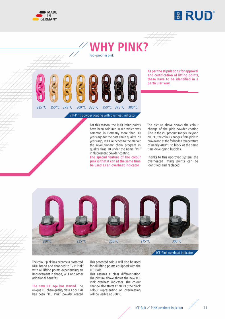
Fool-proof in pinkWHY PINK?
VIP-Pink powder coating with overheat indicator
ICE-Pink overheat indicator
For this reason, the RUD lifting points have been coloured in red which was common in Germany more than 30 years ago for the past chain quality. 20 years ago, RUD launched to the market the revolutionary chain program in quality class 10 under the name “VIP” in fluorescent powder coating.The special feature of the colour pink is that it can at the same time be used as an overheat indicator.
The picture above shows the colour change of the pink powder coating (use in the VIP product range). Beyond 200 °C, the colour changes from pink to brown and at the forbidden temperature of nearly 400 °C to black at the same time developing bubbles.
Thanks to this approved system, the overheated lifting points can be identified and replaced.
The colour pink has become a protected RUD brand and changed to “VIP Pink” with all lifting points experiencing an improvement in shape, WLL and other additional benefits.
The new ICE age has started. The unique ICE chain quality class 12 or 120 has been “ICE Pink” powder coated.
This patented colour will also be used for all lifting points equipped with the ICE-Bolt. This assures a clear differentiation. The picture above shows the new ICE-Pink overheat indicator. The colour change also starts at 200°C; the black colour representing an overheating will be visible at 300°C.
As per the stipulations for approval and certification of lifting points, these have to be identified in a particular way.
225 °C
200°C
250 °C
225 °C
275 °C
250 °C
300 °C
275 °C
320 °C 350 °C
300 °C
375 °C 380 °C
MADEIN
GERMANY
11ICE-Bolt PINK overheat indicator
PowerPoints® in operation
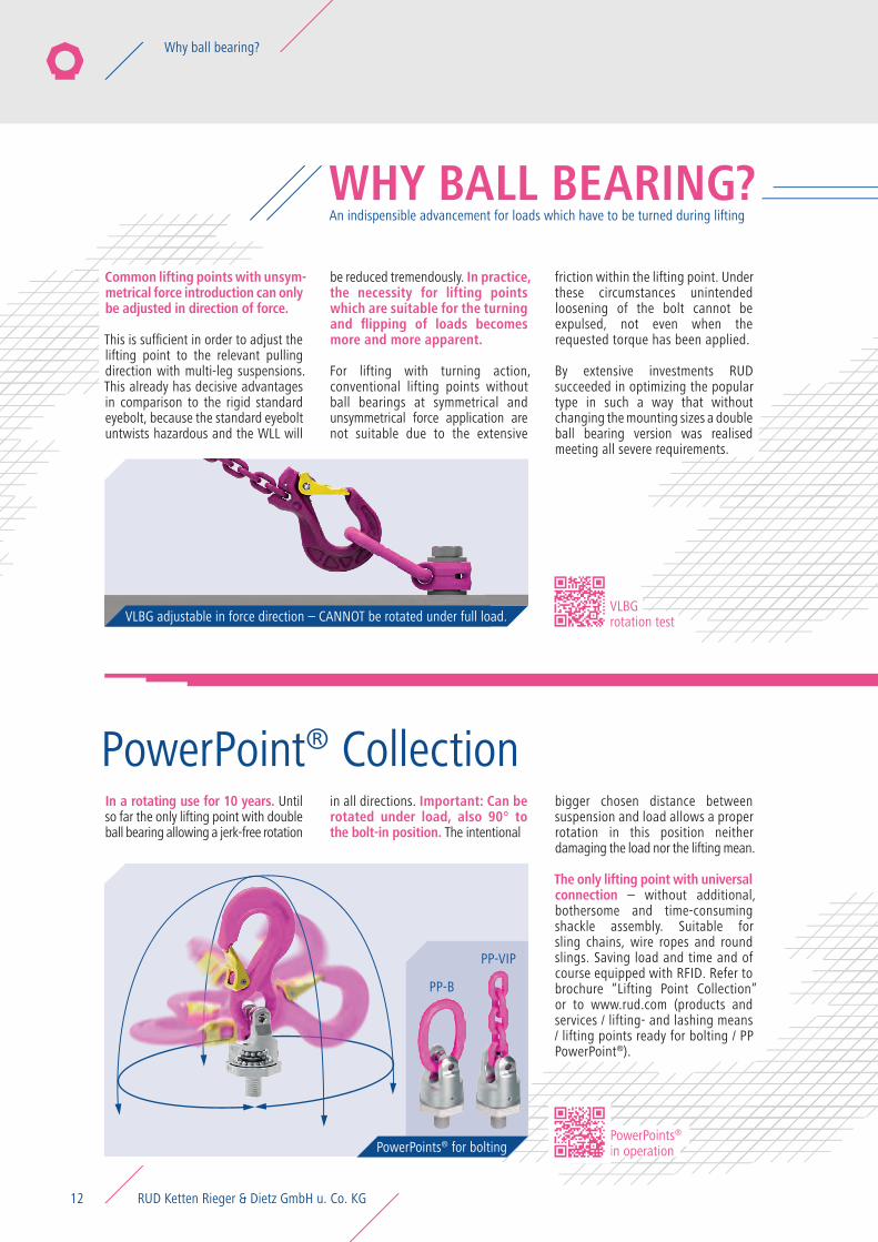
WHY BALL BEARING?
VLBG adjustable in force direction – CANNOT be rotated under full load.VLBG rotation test
An indispensible advancement for loads which have to be turned during lifting
PowerPoint® Collection
PP-B
PP-VIP
PowerPoints® for bolting
In a rotating use for 10 years. Until so far the only lifting point with double ball bearing allowing a jerk-free rotation
in all directions. Important: Can be rotated under load, also 90° to the bolt-in position. The intentional
bigger chosen distance between suspension and load allows a proper rotation in this position neither damaging the load nor the lifting mean.
The only lifting point with universal connection – without additional, bothersome and time-consuming shackle assembly. Suitable for sling chains, wire ropes and round slings. Saving load and time and of course equipped with RFID. Refer to brochure “Lifting Point Collection” or to www.rud.com (products and services / lifting- and lashing means / lifting points ready for bolting / PP PowerPoint®).
Common lifting points with unsym-metrical force introduction can only be adjusted in direction of force.
This is sufficient in order to adjust the lifting point to the relevant pulling direction with multi-leg suspensions. This already has decisive advantages in comparison to the rigid standard eyebolt, because the standard eyebolt untwists hazardous and the WLL will
be reduced tremendously. In practice, the necessity for lifting points which are suitable for the turning and flipping of loads becomes more and more apparent.
For lifting with turning action, conventional lifting points without ball bearings at symmetrical and unsymmetrical force application are not suitable due to the extensive
friction within the lifting point. Under these circumstances unintended loosening of the bolt cannot be expulsed, not even when the requested torque has been applied.
By extensive investments RUD succeeded in optimizing the popular type in such a way that without changing the mounting sizes a double ball bearing version was realised meeting all severe requirements.
RUD Ketten Rieger & Dietz GmbH u. Co. KG12
Why ball bearing?
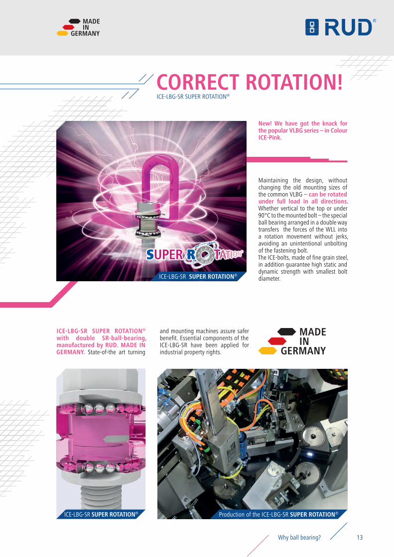
ICE-LBG-SR SUPER ROTATION®
CORRECT ROTATION!
ICE-LBG-SR SUPER ROTATION®
Production of the ICE-LBG-SR SUPER ROTATION®ICE-LBG-SR SUPER ROTATION®
MADEIN
GERMANY
New! We have got the knack for the popular VLBG series – in Colour ICE-Pink.
Maintaining the design, without changing the old mounting sizes of the common VLBG – can be rotated under full load in all directions. Whether vertical to the top or under 90°C to the mounted bolt – the special ball bearing arranged in a double way transfers the forces of the WLL into a rotation movement without jerks, avoiding an unintentional unbolting of the fastening bolt.The ICE-bolts, made of fine grain steel, in addition guarantee high static and dynamic strength with smallest bolt diameter.
ICE-LBG-SR SUPER ROTATION® with double SR-ball-bearing, manufactured by RUD. MADE IN GERMANY. State-of-the art turning
and mounting machines assure safer benefit. Essential components of the ICE-LBG-SR have been applied for industrial property rights.
MADEIN
GERMANY
13Why ball bearing?
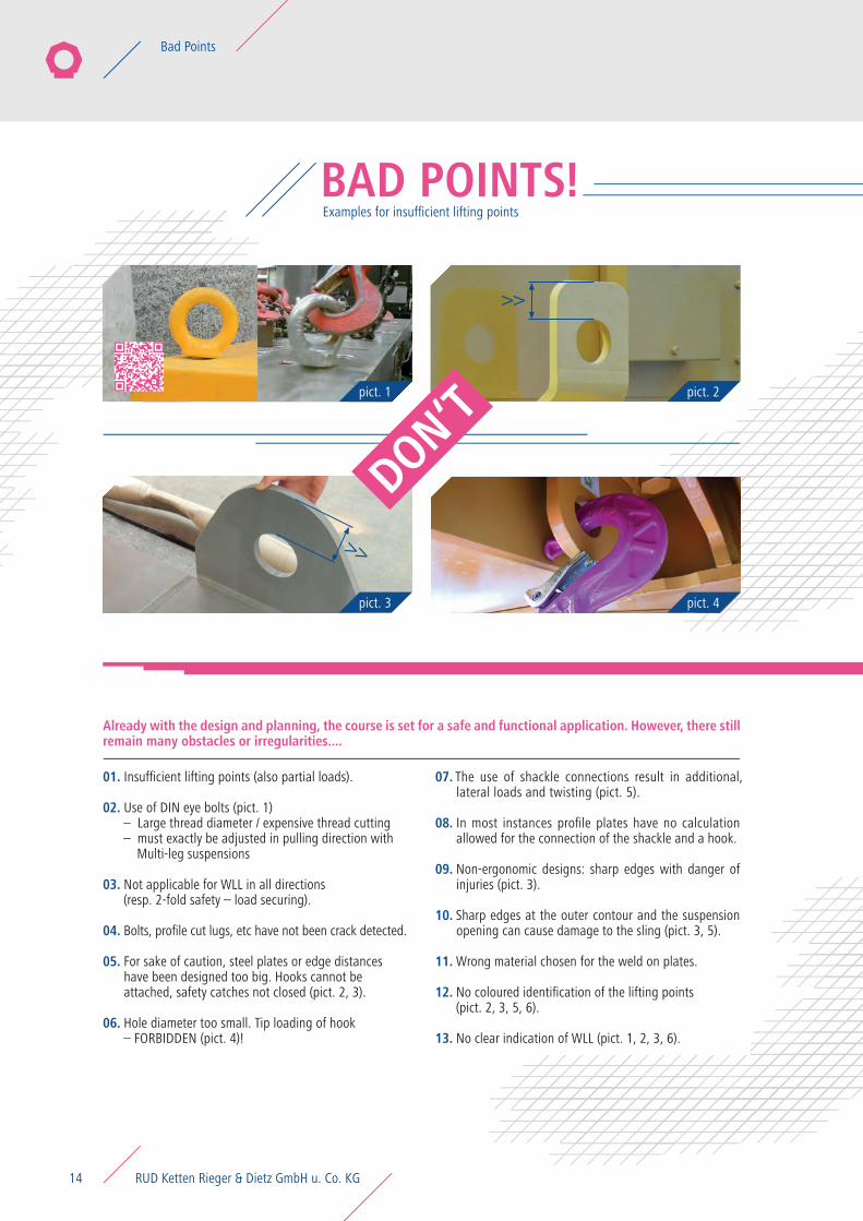
pict. 1 pict. 2
pict. 4pict. 3
BAD POINTS!Examples for insufficient lifting points
DON‘T
Already with the design and planning, the course is set for a safe and functional application. However, there still remain many obstacles or irregularities....
01.
02.
03.
04.
05.
06.
07.
08.
09.
10.
11.
12.
13.
Insufficient lifting points (also partial loads).
Use of DIN eye bolts (pict. 1)– Large thread diameter / expensive thread cutting– must exactly be adjusted in pulling direction with Multi-leg suspensions
Not applicable for WLL in all directions (resp. 2-fold safety – load securing).
Bolts, profile cut lugs, etc have not been crack detected.
For sake of caution, steel plates or edge distances have been designed too big. Hooks cannot be attached, safety catches not closed (pict. 2, 3).
Hole diameter too small. Tip loading of hook – FORBIDDEN (pict. 4)!
The use of shackle connections result in additional, lateral loads and twisting (pict. 5).
In most instances profile plates have no calculation allowed for the connection of the shackle and a hook.
Non-ergonomic designs: sharp edges with danger of injuries (pict. 3).
Sharp edges at the outer contour and the suspension opening can cause damage to the sling (pict. 3, 5).
Wrong material chosen for the weld on plates.
No coloured identification of the lifting points (pict. 2, 3, 5, 6).
No clear indication of WLL (pict. 1, 2, 3, 6).
>>
>>
RUD Ketten Rieger & Dietz GmbH u. Co. KG14
Bad Points
Insist on approved lifting points from RUD “Made in Germany”!
APPLICATION EXAMPLES
B C
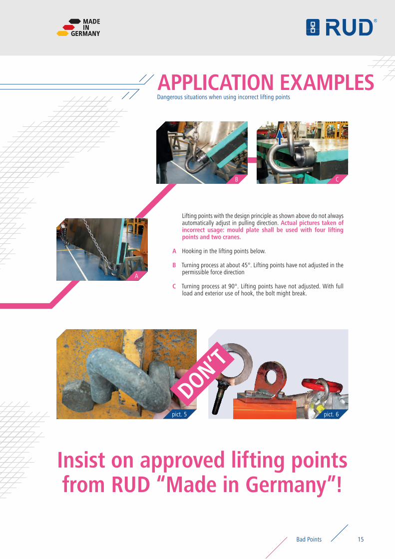
Lifting points with the design principle as shown above do not always automatically adjust in pulling direction. Actual pictures taken of incorrect usage: mould plate shall be used with four lifting points and two cranes.
Hooking in the lifting points below.
Turning process at about 45°. Lifting points have not adjusted in the permissible force direction
Turning process at 90°. Lifting points have not adjusted. With full load and exterior use of hook, the bolt might break.
A
B
C
pict. 5 pict. 6
DON‘T
Dangerous situations when using incorrect lifting points
A
MADEIN
GERMANY
15
MADEIN
GERMANY
Bad Points
4:1 min. safety factor for lifting
standard feature: RFID
full working load in all directions
dimensioning programs
GOOD POINTS!
01.
05.
02. 03.
04. 06.
01.
02.
03.
04.
05.
06.
07.
08.
09.
10.
11.
12.
13.
14.
15.
16.
17.
18.
According to European Machinery Directive 2006/42/EC.
Safety factor 4:1 against breakage in any loading direction.
Full working load in all directions.
Dimensioning programs for finding the correct WLL and reduced construction times thanks to 2D- and 3D data free of charge.
Lifting points for bolting: Standard equipment with RFID chip.
RUD ICE- and VIP Pink Powder Coating as a clear marking for the lifting point (RUD recognition feature) and as a heat indicator up from 200° C.
Turnable Lifting points are rotating 360° in mounted condition.
Distinctive WLL indication based on worst case scenario.
All load bearing parts are 100 % crack detected.
Patented wear marks for easily determining the replacement state of wear.
Convincing RUD advantages
Due to octagon shape clear determination to commercial lifting points.
Ergonomic and innovative design.
Smallest possible design at highest WLL due to high tensile and heat treated materials, small thread diameters and clear defined welding parameters.
Comprehensive choice of variants ready for bolting and welding.
WLL range from 80 kilos to 200 t.
Designed for at least 20,000 load cycles, tested at 50 % overload.
ChromeVI-free coating at all galvanised components.
Made in Germany.
Regard the operation manual before and during usage of the RUD lifting points.
Machinery Directive 2006/42/EC
MD2006/42/EC
ICE-Pink overheat indicator
VIP-Pink overheat indicator
4:1
Convincing RUD advantages
RUD Ketten Rieger & Dietz GmbH u. Co. KG16
Good Points
octagon shape/contour
11. 18.
LIFTING
PowerPoint® PP-SVRS STARPOINT
VWBG ICE-LBG-SR SUPER ROTATION®
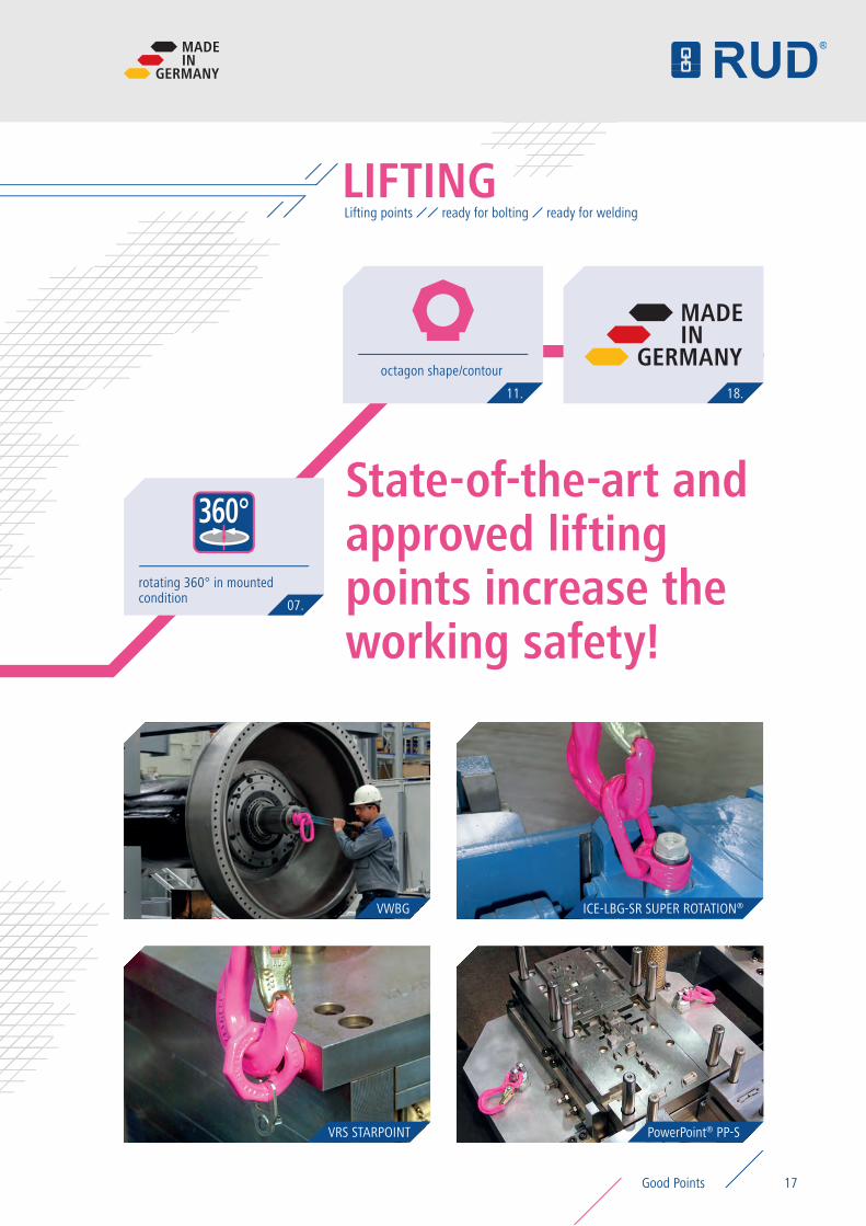
State-of-the-art and approved lifting points increase the working safety!
rotating 360° in mounted condition 07.
Lifting points ready for bolting ready for welding
MADEIN
GERMANY
360°
MADEIN
GERMANY
17Good Points
ICE-LBG-SRICE Load ring for bolting Super Rotation
18 RUD Ketten Rieger & Dietz GmbH u. Co. KG18
Lifting points – ready for bolting ICE-LBG-SR
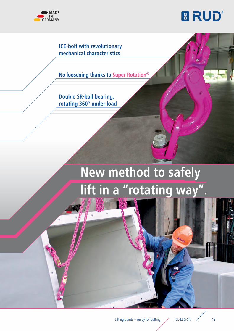
ICE-bolt with revolutionary mechanical characteristics
New method to safely lift in a “rotating way”.
No loosening thanks to Super Rotation®
Double SR-ball bearing,rotating 360° under load
19
MADEIN
GERMANY
19ICE-LBG-SRLifting points – ready for bolting
Product features ICE-LBG-SR
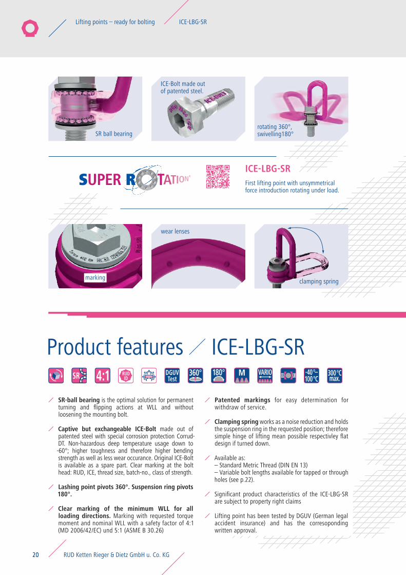
First lifting point with unsymmetrical force introduction rotating under load.
ICE-LBG-SR
20
4:1 RUDID
DGUVTestSR 360° 180° M VARIO 300°C
max.-40°–100°C
ICE-Bolt made out of patented steel.
marking
SR ball bearing
clamping spring
rotating 360°,swivelling180°
wear lenses
SR-ball bearing is the optimal solution for permanent turning and flipping actions at WLL and without loosening the mounting bolt.
Captive but exchangeable ICE-Bolt made out of patented steel with special corrosion protection Corrud-DT. Non-hazardous deep temperature usage down to -60°; higher toughness and therefore higher bending strength as well as less wear occurance. Original ICE-Bolt is available as a spare part. Clear marking at the bolt head: RUD, ICE, thread size, batch-no., class of strength.
Lashing point pivots 360°. Suspension ring pivots 180°.
Clear marking of the minimum WLL for all loading directions. Marking with requested torque moment and nominal WLL with a safety factor of 4:1 (MD 2006/42/EC) und 5:1 (ASME B 30.26)
Patented markings for easy determination for withdraw of service.
Clamping spring works as a noise reduction and holds the suspension ring in the requested position; therefore simple hinge of lifting mean possible respectivley flat design if turned down.
Available as: – Standard Metric Thread (DIN EN 13)– Variable bolt lengths available for tapped or through holes (see p.22).
Significant product characteristics of the ICE-LBG-SR are subject to property right claims
Lifting point has been tested by DGUV (German legal accident insurance) and has the corresoponding written approval.
RUD Ketten Rieger & Dietz GmbH u. Co. KG20
Lifting points – ready for bolting ICE-LBG-SR
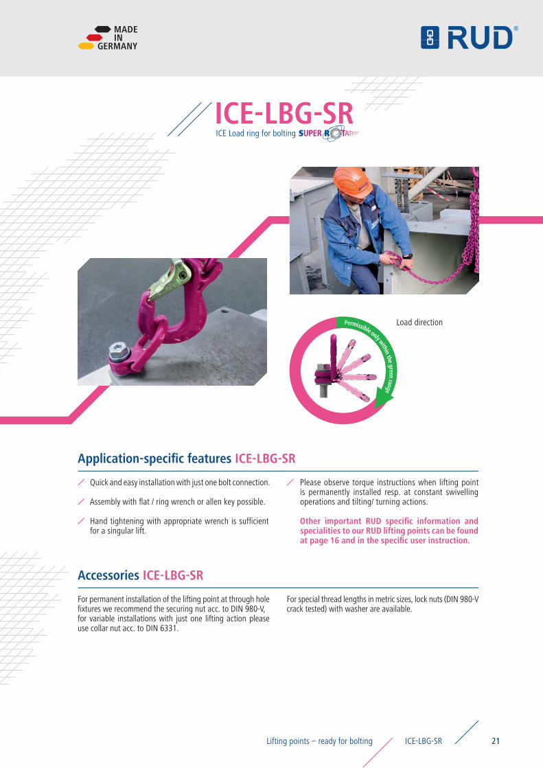
ICE Load ring for bolting ICE-LBG-SR
21
Permissible only within the green range
Load direction
Please observe torque instructions when lifting point is permanently installed resp. at constant swivelling operations and tilting/ turning actions.
Other important RUD specific information and specialities to our RUD lifting points can be found at page 16 and in the specific user instruction.
Quick and easy installation with just one bolt connection.
Assembly with flat / ring wrench or allen key possible.
Hand tightening with appropriate wrench is sufficient for a singular lift.
Application-specific features ICE-LBG-SR
For permanent installation of the lifting point at through hole fixtures we recommend the securing nut acc. to DIN 980-V, for variable installations with just one lifting action please use collar nut acc. to DIN 6331.
For special thread lengths in metric sizes, lock nuts (DIN 980-V crack tested) with washer are available.
Accessories ICE-LBG-SR
MADEIN
GERMANY
21ICE-LBG-SRLifting points – ready for bolting
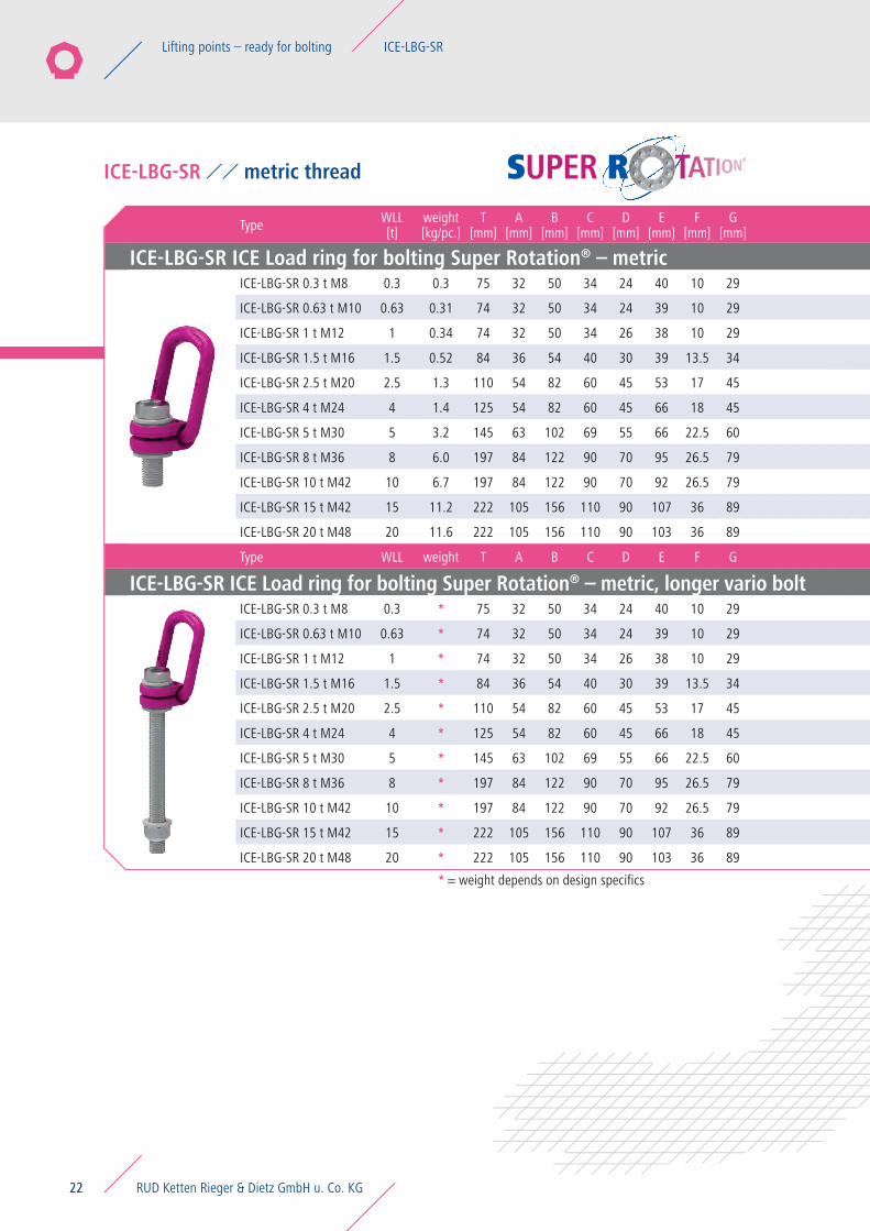
Type WLL[t]
weight[kg/pc.]
T[mm]
A[mm]
B[mm]
C[mm]
D[mm]
E[mm]
F[mm]
G[mm]
H[mm]
I[mm]
K[mm]
L[mm] M N
[mm]torque [Nm] Ref. No.
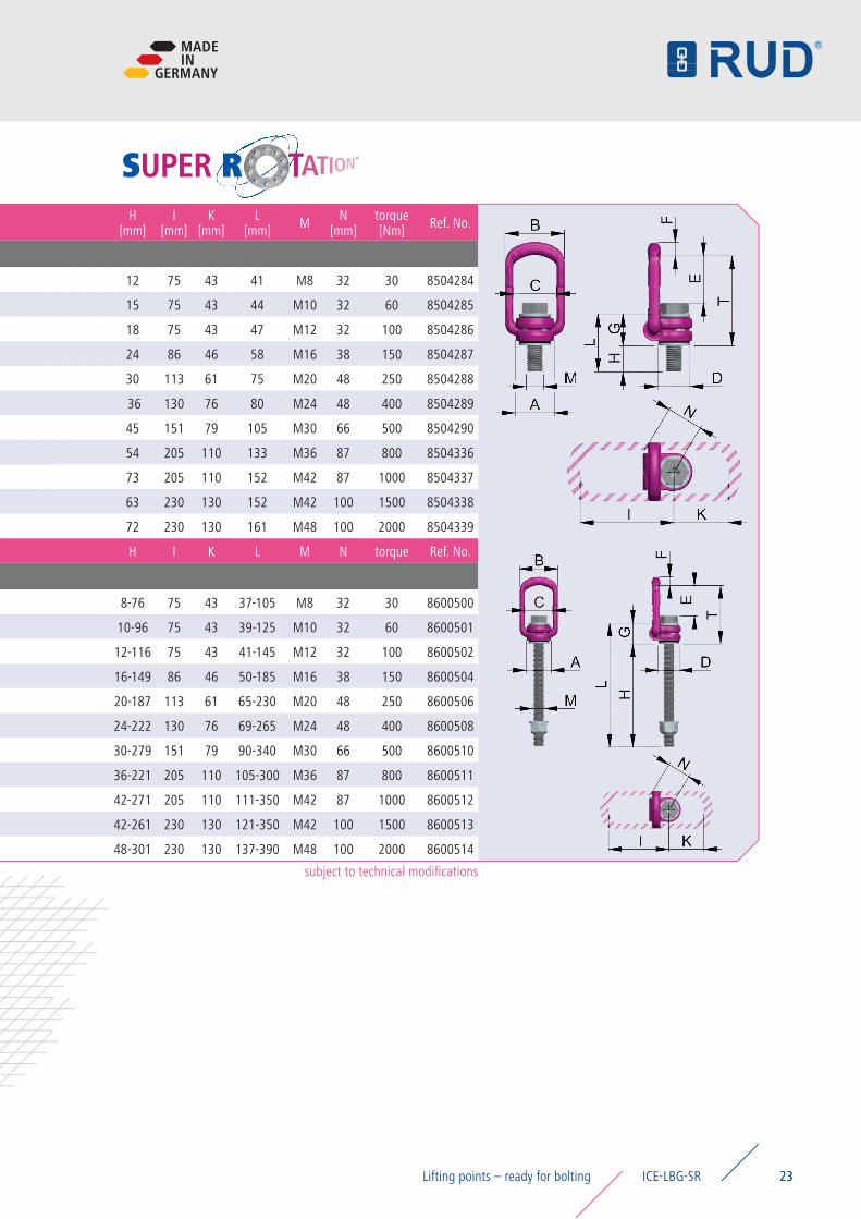
ICE-LBG-SR ICE Load ring for bolting Super Rotation® – metricICE-LBG-SR 0.3 t M8 0.3 0.3 75 32 50 34 24 40 10 29 12 75 43 41 M8 32 30 8504284
ICE-LBG-SR 0.63 t M10 0.63 0.31 74 32 50 34 24 39 10 29 15 75 43 44 M10 32 60 8504285
ICE-LBG-SR 1 t M12 1 0.34 74 32 50 34 26 38 10 29 18 75 43 47 M12 32 100 8504286
ICE-LBG-SR 1.5 t M16 1.5 0.52 84 36 54 40 30 39 13.5 34 24 86 46 58 M16 38 150 8504287
ICE-LBG-SR 2.5 t M20 2.5 1.3 110 54 82 60 45 53 17 45 30 113 61 75 M20 48 250 8504288
ICE-LBG-SR 4 t M24 4 1.4 125 54 82 60 45 66 18 45 36 130 76 80 M24 48 400 8504289
ICE-LBG-SR 5 t M30 5 3.2 145 63 102 69 55 66 22.5 60 45 151 79 105 M30 66 500 8504290
ICE-LBG-SR 8 t M36 8 6.0 197 84 122 90 70 95 26.5 79 54 205 110 133 M36 87 800 8504336
ICE-LBG-SR 10 t M42 10 6.7 197 84 122 90 70 92 26.5 79 73 205 110 152 M42 87 1000 8504337
ICE-LBG-SR 15 t M42 15 11.2 222 105 156 110 90 107 36 89 63 230 130 152 M42 100 1500 8504338
ICE-LBG-SR 20 t M48 20 11.6 222 105 156 110 90 103 36 89 72 230 130 161 M48 100 2000 8504339
Type WLL weight T A B C D E F G H I K L M N torque Ref. No.
ICE-LBG-SR ICE Load ring for bolting Super Rotation® – metric, longer vario boltICE-LBG-SR 0.3 t M8 0.3 * 75 32 50 34 24 40 10 29 8-76 75 43 37-105 M8 32 30 8600500
ICE-LBG-SR 0.63 t M10 0.63 * 74 32 50 34 24 39 10 29 10-96 75 43 39-125 M10 32 60 8600501
ICE-LBG-SR 1 t M12 1 * 74 32 50 34 26 38 10 29 12-116 75 43 41-145 M12 32 100 8600502
ICE-LBG-SR 1.5 t M16 1.5 * 84 36 54 40 30 39 13.5 34 16-149 86 46 50-185 M16 38 150 8600504
ICE-LBG-SR 2.5 t M20 2.5 * 110 54 82 60 45 53 17 45 20-187 113 61 65-230 M20 48 250 8600506
ICE-LBG-SR 4 t M24 4 * 125 54 82 60 45 66 18 45 24-222 130 76 69-265 M24 48 400 8600508
ICE-LBG-SR 5 t M30 5 * 145 63 102 69 55 66 22.5 60 30-279 151 79 90-340 M30 66 500 8600510
ICE-LBG-SR 8 t M36 8 * 197 84 122 90 70 95 26.5 79 36-221 205 110 105-300 M36 87 800 8600511
ICE-LBG-SR 10 t M42 10 * 197 84 122 90 70 92 26.5 79 42-271 205 110 111-350 M42 87 1000 8600512
ICE-LBG-SR 15 t M42 15 * 222 105 156 110 90 107 36 89 42-261 230 130 121-350 M42 100 1500 8600513
ICE-LBG-SR 20 t M48 20 * 222 105 156 110 90 103 36 89 48-301 230 130 137-390 M48 100 2000 8600514
* = weight depends on design specifics
22
ICE-LBG-SR metric thread
RUD Ketten Rieger & Dietz GmbH u. Co. KG22
Lifting points – ready for bolting ICE-LBG-SR
Type WLL[t]
weight[kg/pc.]
T[mm]
A[mm]
B[mm]
C[mm]
D[mm]
E[mm]
F[mm]
G[mm]
H[mm]
I[mm]
K[mm]
L[mm] M N
[mm]torque [Nm] Ref. No.
ICE-LBG-SR ICE Load ring for bolting Super Rotation® – metricICE-LBG-SR 0.3 t M8 0.3 0.3 75 32 50 34 24 40 10 29 12 75 43 41 M8 32 30 8504284
ICE-LBG-SR 0.63 t M10 0.63 0.31 74 32 50 34 24 39 10 29 15 75 43 44 M10 32 60 8504285
ICE-LBG-SR 1 t M12 1 0.34 74 32 50 34 26 38 10 29 18 75 43 47 M12 32 100 8504286
ICE-LBG-SR 1.5 t M16 1.5 0.52 84 36 54 40 30 39 13.5 34 24 86 46 58 M16 38 150 8504287
ICE-LBG-SR 2.5 t M20 2.5 1.3 110 54 82 60 45 53 17 45 30 113 61 75 M20 48 250 8504288
ICE-LBG-SR 4 t M24 4 1.4 125 54 82 60 45 66 18 45 36 130 76 80 M24 48 400 8504289
ICE-LBG-SR 5 t M30 5 3.2 145 63 102 69 55 66 22.5 60 45 151 79 105 M30 66 500 8504290
ICE-LBG-SR 8 t M36 8 6.0 197 84 122 90 70 95 26.5 79 54 205 110 133 M36 87 800 8504336
ICE-LBG-SR 10 t M42 10 6.7 197 84 122 90 70 92 26.5 79 73 205 110 152 M42 87 1000 8504337
ICE-LBG-SR 15 t M42 15 11.2 222 105 156 110 90 107 36 89 63 230 130 152 M42 100 1500 8504338
ICE-LBG-SR 20 t M48 20 11.6 222 105 156 110 90 103 36 89 72 230 130 161 M48 100 2000 8504339
Type WLL weight T A B C D E F G H I K L M N torque Ref. No.
ICE-LBG-SR ICE Load ring for bolting Super Rotation® – metric, longer vario boltICE-LBG-SR 0.3 t M8 0.3 * 75 32 50 34 24 40 10 29 8-76 75 43 37-105 M8 32 30 8600500
ICE-LBG-SR 0.63 t M10 0.63 * 74 32 50 34 24 39 10 29 10-96 75 43 39-125 M10 32 60 8600501
ICE-LBG-SR 1 t M12 1 * 74 32 50 34 26 38 10 29 12-116 75 43 41-145 M12 32 100 8600502
ICE-LBG-SR 1.5 t M16 1.5 * 84 36 54 40 30 39 13.5 34 16-149 86 46 50-185 M16 38 150 8600504
ICE-LBG-SR 2.5 t M20 2.5 * 110 54 82 60 45 53 17 45 20-187 113 61 65-230 M20 48 250 8600506
ICE-LBG-SR 4 t M24 4 * 125 54 82 60 45 66 18 45 24-222 130 76 69-265 M24 48 400 8600508
ICE-LBG-SR 5 t M30 5 * 145 63 102 69 55 66 22.5 60 30-279 151 79 90-340 M30 66 500 8600510
ICE-LBG-SR 8 t M36 8 * 197 84 122 90 70 95 26.5 79 36-221 205 110 105-300 M36 87 800 8600511
ICE-LBG-SR 10 t M42 10 * 197 84 122 90 70 92 26.5 79 42-271 205 110 111-350 M42 87 1000 8600512
ICE-LBG-SR 15 t M42 15 * 222 105 156 110 90 107 36 89 42-261 230 130 121-350 M42 100 1500 8600513
ICE-LBG-SR 20 t M48 20 * 222 105 156 110 90 103 36 89 48-301 230 130 137-390 M48 100 2000 8600514
subject to technical modifications
23
MADEIN
GERMANY
23ICE-LBG-SRLifting points – ready for bolting
24
VLBGVIP Load ring for bolting
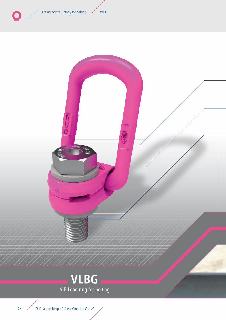
RUD Ketten Rieger & Dietz GmbH u. Co. KG24
Lifting points – ready for bolting VLBG
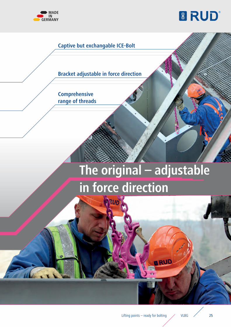
The original – adjustable in force direction
25
Bracket adjustable in force direction
Captive but exchangable ICE-Bolt
Comprehensive range of threads
MADEIN
GERMANY
25VLBGLifting points – ready for bolting
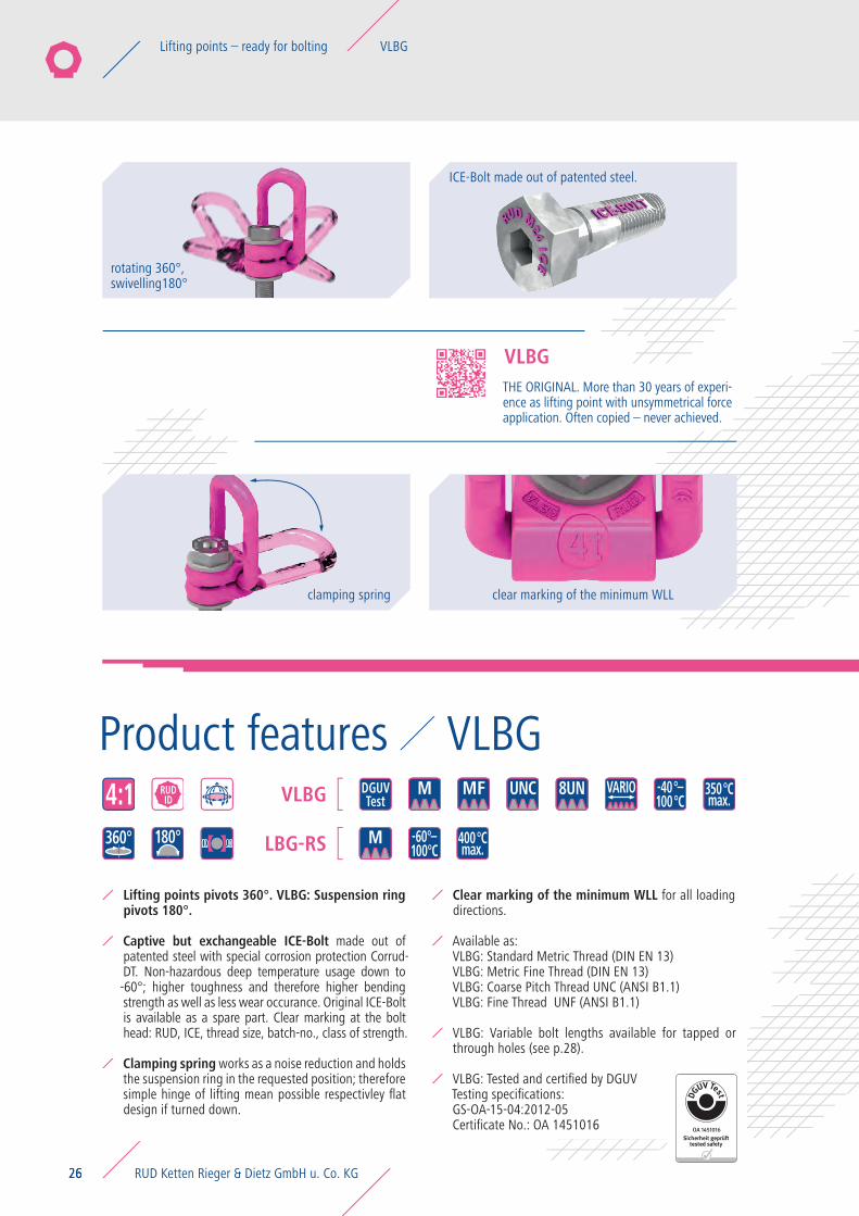
Product features VLBG
THE ORIGINAL. More than 30 years of experi-ence as lifting point with unsymmetrical force application. Often copied – never achieved.
VLBG
26
ICE-Bolt made out of patented steel.
clamping spring
rotating 360°,swivelling180°
UNCMF 8UN -40°–100°C
350°Cmax.4:1 RUD
IDDGUVTest
360° 180° M
M VARIOVLBG
LBG-RS 400°Cmax.
-60°–100°C
clear marking of the minimum WLL
26
Lifting points pivots 360°. VLBG: Suspension ring pivots 180°.
Captive but exchangeable ICE-Bolt made out of patented steel with special corrosion protection Corrud-DT. Non-hazardous deep temperature usage down to -60°; higher toughness and therefore higher bending strength as well as less wear occurance. Original ICE-Bolt is available as a spare part. Clear marking at the bolt head: RUD, ICE, thread size, batch-no., class of strength.
Clamping spring works as a noise reduction and holds the suspension ring in the requested position; therefore simple hinge of lifting mean possible respectivley flat design if turned down.
Clear marking of the minimum WLL for all loading directions.
Available as: VLBG: Standard Metric Thread (DIN EN 13)VLBG: Metric Fine Thread (DIN EN 13)VLBG: Coarse Pitch Thread UNC (ANSI B1.1)VLBG: Fine Thread UNF (ANSI B1.1)
VLBG: Variable bolt lengths available for tapped or through holes (see p.28).
VLBG: Tested and certified by DGUVTesting specifications: GS-OA-15-04:2012-05Certificate No.: OA 1451016
RUD Ketten Rieger & Dietz GmbH u. Co. KG26
Lifting points – ready for bolting VLBG
VIP ring bolt with threadsVLBG
2727
Permissible only within the green range
LBG-RS: Component made out of 1.4571: therefore higher resistancy against intergranular corrosion.
Quick and easy installation with just one bolt connection.
Assembly with flat / ring wrench or allen key possible.
Hand tightening with appropriate wrench is sufficient for a singular lift.
Accessories VLBG
Product features Application-specific features VLBG
Please observe torque instructions when lifting point is permanently installed resp. at constant swivelling operations and tilting/ turning actions.
Other important RUD specific information and specialities to our RUD lifting points can be found at page 16 and in the specific user instruction.
For permanent installation of the lifting point at through hole fixtures we recommend the securing nut acc. to DIN 980-V, for variable installations with just one lifting action please use collar nut acc. to DIN 6331.
For special thread lengths in metric sizes, lock nuts (DIN 980-V crack tested) with washer are available.
MADEIN
GERMANY
27VLBGLifting points – ready for bolting
Type WLL[t]
weight[kg/pc.]
T[mm]
A[mm]
B[mm]
C[mm]
D[mm]
E[mm]
F[mm]
G[mm]
H[mm]
I[mm]
K[mm]
L[mm] M N
[mm]torque[Nm] Ref. No.
VLBG VIP Load ring for bolting – metricVLBG 0.3t M8 0.3 0.3 75 30 54 34 24 40 10 29 11 75 45 40 M8 32 30 8500821
VLBG 0.63t M10 0.63 0.32 75 30 54 34 24 39 10 29 16 75 45 45 M10 32 60 8500822
VLBG 1t M12 1 0.33 75 32 54 34 26 38 10 29 21 75 45 50 M12 32 100 8500823
VLBG 1.2t M14 (H=21) 1.2 0.52 85 33 56 36 30 39 13.5 36 21 86 47 57 M14 38 120 8600399
VLBG 1.5t M16 1.5 0.55 85 33 56 36 30 39 13.5 36 24 86 47 60 M16 38 150 8500824
VLBG 2t M18 (H=27) 2 1.3 110 50 82 54 45 55 16.5 43 27 113 64 70 M18 48 200 8600384
VLBG 2.5t M20 2.5 1.3 110 50 82 54 45 55 16.5 43 32 113 64 75 M20 48 250 8500826
VLBG 2.5t M22 (H=33) 2.5 1.31 110 50 82 54 45 54 16.5 43 33 113 64 75 M22 48 250 8600385
VLBG 4t M24 4 1.5 125 50 82 54 45 67 18 43 37 130 78 80 M24 48 400 8500827
VLBG 4t M27 4 3.1 147 60 103 65 60 69 22.5 61 39 151 80 100 M27 67 400 7983658
VLBG 5t M30 5 3.3 147 60 103 65 60 67 22.5 61 49 151 80 110 M30 67 500 8500828
VLBG 7t M36 (So-Schr.) 7 3.4 146 60 103 65 60 74 22.5 55 52 151 80 107 M36 67 700 8500829
VLBG 8t M36 8 6.2 197 77 122 82 70 97 26.5 77 63 205 110 140 M36 87 800 7983553
VLBG 10t M42 10 6.7 197 77 122 82 70 94 26.5 77 73 205 110 150 M42 70 1000 7983554
VLBG 15t M42 15 10.9 222 95 156 100 85 109 36 87 63 230 130 150 M42 100 1500 7982966
VLBG 20t M48 20 11.6 222 95 156 100 95 105 36 87 73 230 130 160 M48 100 2000 7982967
Type WLL weight T A B C D E F G H I K L M N torque Ref. No.
VLBG VIP Load ring for bolting – metric with longer vario boltVLBG 0.3t M8 0.3 * 75 30 54 34 24 40 10 29 8-76 75 45 37-105 M8 32 30 8600280
VLBG 0.63t M10 0.63 * 75 30 54 34 24 39 10 29 10-96 75 45 39-125 M10 32 60 8600281
VLBG 1t M12 1 * 75 32 54 34 26 38 10 29 12-116 75 45 41-145 M12 32 100 8600382
VLBG 1.2t M14 1.2 * 85 33 56 36 30 39 13.5 36 14-34 86 47 50-70 M14 38 120 8600399
VLBG 1.5t M16 1.5 * 85 33 56 36 30 39 13.5 36 16-149 86 47 52-185 M16 38 150 8600383
VLBG 2t M18 2 * 110 50 82 54 45 55 16.5 43 18-47 113 64 61-90 M18 48 200 8600384
VLBG 2.5t M20 2.5 * 110 50 82 54 45 55 16.5 43 20-187 113 64 63-230 M20 48 250 8600385
VLBG 2.5t M22 2.5 * 110 50 82 54 45 54 16.5 43 22-57 113 64 65-100 M22 48 250 8600385
VLBG 4t M24 4 * 125 50 82 54 45 67 18 43 24-222 130 78 67-265 M24 48 400 8600386
VLBG 4t M27 4 * 147 60 103 65 60 69 22.5 61 27-239 151 80 88-300 M27 67 400 8600387
VLBG 5t M30 5 * 147 60 103 65 60 67 22.5 61 30-279 151 80 91-340 M30 67 500 8600388
VLBG 8t M36 8 * 197 77 122 82 70 97 26.5 77 36-223 205 110 113-300 M36 87 800 8600289
VLBG 10t M42 10 * 197 77 122 82 70 94 26.5 77 42-273 205 110 119-350 M42 70 1000 8600290
VLBG 15t M42 15 * 222 95 156 100 85 109 36 87 42-263 230 130 129-350 M42 100 1500 8600291
VLBG 20t M48 20 * 222 95 156 100 95 105 36 87 48-303 230 130 135-350 M48 100 2000 8600292* = weight depends on design specifics
28
VLBG metric thread
RUD Ketten Rieger & Dietz GmbH u. Co. KG28
Lifting points – ready for bolting VLBG
Type WLL[t]
weight[kg/pc.]
T[mm]
A[mm]
B[mm]
C[mm]
D[mm]
E[mm]
F[mm]
G[mm]
H[mm]
I[mm]
K[mm]
L[mm] M N
[mm]torque[Nm] Ref. No.
VLBG VIP Load ring for bolting – metricVLBG 0.3t M8 0.3 0.3 75 30 54 34 24 40 10 29 11 75 45 40 M8 32 30 8500821
VLBG 0.63t M10 0.63 0.32 75 30 54 34 24 39 10 29 16 75 45 45 M10 32 60 8500822
VLBG 1t M12 1 0.33 75 32 54 34 26 38 10 29 21 75 45 50 M12 32 100 8500823
VLBG 1.2t M14 (H=21) 1.2 0.52 85 33 56 36 30 39 13.5 36 21 86 47 57 M14 38 120 8600399
VLBG 1.5t M16 1.5 0.55 85 33 56 36 30 39 13.5 36 24 86 47 60 M16 38 150 8500824
VLBG 2t M18 (H=27) 2 1.3 110 50 82 54 45 55 16.5 43 27 113 64 70 M18 48 200 8600384
VLBG 2.5t M20 2.5 1.3 110 50 82 54 45 55 16.5 43 32 113 64 75 M20 48 250 8500826
VLBG 2.5t M22 (H=33) 2.5 1.31 110 50 82 54 45 54 16.5 43 33 113 64 75 M22 48 250 8600385
VLBG 4t M24 4 1.5 125 50 82 54 45 67 18 43 37 130 78 80 M24 48 400 8500827
VLBG 4t M27 4 3.1 147 60 103 65 60 69 22.5 61 39 151 80 100 M27 67 400 7983658
VLBG 5t M30 5 3.3 147 60 103 65 60 67 22.5 61 49 151 80 110 M30 67 500 8500828
VLBG 7t M36 (So-Schr.) 7 3.4 146 60 103 65 60 74 22.5 55 52 151 80 107 M36 67 700 8500829
VLBG 8t M36 8 6.2 197 77 122 82 70 97 26.5 77 63 205 110 140 M36 87 800 7983553
VLBG 10t M42 10 6.7 197 77 122 82 70 94 26.5 77 73 205 110 150 M42 70 1000 7983554
VLBG 15t M42 15 10.9 222 95 156 100 85 109 36 87 63 230 130 150 M42 100 1500 7982966
VLBG 20t M48 20 11.6 222 95 156 100 95 105 36 87 73 230 130 160 M48 100 2000 7982967
Type WLL weight T A B C D E F G H I K L M N torque Ref. No.
VLBG VIP Load ring for bolting – metric with longer vario boltVLBG 0.3t M8 0.3 * 75 30 54 34 24 40 10 29 8-76 75 45 37-105 M8 32 30 8600280
VLBG 0.63t M10 0.63 * 75 30 54 34 24 39 10 29 10-96 75 45 39-125 M10 32 60 8600281
VLBG 1t M12 1 * 75 32 54 34 26 38 10 29 12-116 75 45 41-145 M12 32 100 8600382
VLBG 1.2t M14 1.2 * 85 33 56 36 30 39 13.5 36 14-34 86 47 50-70 M14 38 120 8600399
VLBG 1.5t M16 1.5 * 85 33 56 36 30 39 13.5 36 16-149 86 47 52-185 M16 38 150 8600383
VLBG 2t M18 2 * 110 50 82 54 45 55 16.5 43 18-47 113 64 61-90 M18 48 200 8600384
VLBG 2.5t M20 2.5 * 110 50 82 54 45 55 16.5 43 20-187 113 64 63-230 M20 48 250 8600385
VLBG 2.5t M22 2.5 * 110 50 82 54 45 54 16.5 43 22-57 113 64 65-100 M22 48 250 8600385
VLBG 4t M24 4 * 125 50 82 54 45 67 18 43 24-222 130 78 67-265 M24 48 400 8600386
VLBG 4t M27 4 * 147 60 103 65 60 69 22.5 61 27-239 151 80 88-300 M27 67 400 8600387
VLBG 5t M30 5 * 147 60 103 65 60 67 22.5 61 30-279 151 80 91-340 M30 67 500 8600388
VLBG 8t M36 8 * 197 77 122 82 70 97 26.5 77 36-223 205 110 113-300 M36 87 800 8600289
VLBG 10t M42 10 * 197 77 122 82 70 94 26.5 77 42-273 205 110 119-350 M42 70 1000 8600290
VLBG 15t M42 15 * 222 95 156 100 85 109 36 87 42-263 230 130 129-350 M42 100 1500 8600291
VLBG 20t M48 20 * 222 95 156 100 95 105 36 87 48-303 230 130 135-350 M48 100 2000 8600292subject to technical modifications
29
MADEIN
GERMANY
29VLBGLifting points – ready for bolting
Type WLL[t]
weight[kg/pc.]
T[mm]
A[mm]
B[mm]
C[mm]
D[mm]
E[mm]
F[mm]
G[mm]
H[mm]
I[mm]
K[mm]
L[mm] M N
[mm]torque[Nm] Ref. No.
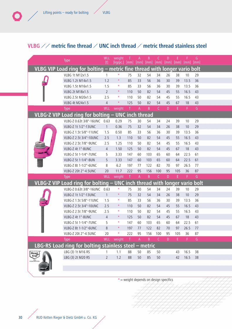
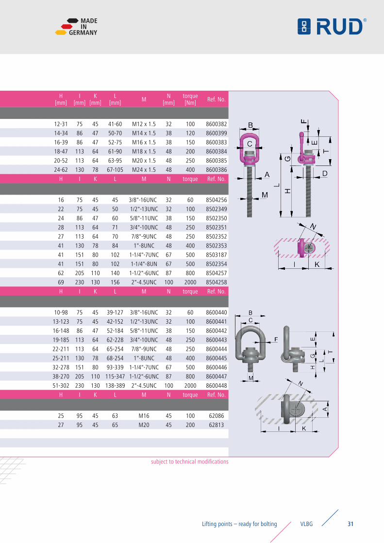
VLBG VIP Load ring for bolting – metric fine thread with longer vario boltVLBG 1t M12x1.5 1 * 75 32 54 34 26 38 10 29 12-31 75 45 41-60 M12 x 1.5 32 100 8600382
VLBG 1.2t M14x1.5 1.2 * 85 33 56 36 30 39 13.5 36 14-34 86 47 50-70 M14 x 1.5 38 120 8600399
VLBG 1.5t M16x1.5 1.5 * 85 33 56 36 30 39 13.5 36 16-39 86 47 52-75 M16 x 1.5 38 150 8600383
VLBG 2t M18x1.5 2 * 110 50 82 54 45 55 16.5 43 18-47 113 64 61-90 M18 x 1.5 48 200 8600384
VLBG 2.5t M20x1.5 2.5 * 110 50 82 54 45 55 16.5 43 20-52 113 64 63-95 M20 x 1.5 48 250 8600385
VLBG 4t M24x1.5 4 * 125 50 82 54 45 67 18 43 24-62 130 78 67-105 M24 x 1.5 48 400 8600386
Type WLL weight T A B C D E F G H I K L M N torque Ref. No.
VLBG-Z VIP Load ring for bolting – UNC inch threadVLBG-Z 0.63t 3/8"-16UNC 0.63 0.29 75 30 54 34 24 39 10 29 16 75 45 45 3/8"-16UNC 32 60 8504256
VLBG-Z 1t 1/2"-13UNC 1 0.36 75 32 54 34 26 38 10 29 22 75 45 50 1/2"-13UNC 32 100 8502349
VLBG-Z 1.5t 5/8"-11UNC 1.5 0.50 85 33 56 36 30 39 13.5 36 24 86 47 60 5/8"-11UNC 38 150 8502350
VLBG-Z 2.5t 3/4"-10UNC 2.5 1.3 110 50 82 54 45 55 16.5 43 28 113 64 71 3/4"-10UNC 48 250 8502351
VLBG-Z 2.5t 7/8"-9UNC 2.5 1.25 110 50 82 54 45 55 16.5 43 27 113 64 70 7/8"-9UNC 48 250 8502352
VLBG-Z 4t 1"-8UNC 4 1.50 125 50 82 54 45 67 18 43 41 130 78 84 1"-8UNC 48 400 8502353
VLBG-Z 5t 1-1/4"-7UNC 5 3.33 147 60 103 65 60 64 22.5 61 41 151 80 102 1-1/4"-7UNC 67 500 8503187
VLBG-Z 5t 1-1/4"-8UN 5 3.33 147 60 103 65 60 64 22.5 61 41 151 80 102 1-1/4"-8UN 67 500 8502354
VLBG-Z 8t 1-1/2"-6UNC 8 6.2 197 77 122 82 70 97 26.5 77 62 205 110 140 1-1/2"-6UNC 87 800 8504257
VLBG-Z 20t 2"-4.5UNC 20 11.7 222 95 156 100 95 105 36 87 69 230 130 156 2"-4.5UNC 100 2000 8504258
Type WLL weight T A B C D E F G H I K L M N torque Ref. No.
VLBG-Z VIP Load ring for bolting – UNC inch thread with longer vario boltVLBG-Z 0.63t 3/8"-16UNC 0.63 * 75 30 54 34 24 39 10 29 10-98 75 45 39-127 3/8"-16UNC 32 60 8600440
VLBG-Z 1t 1/2"-13UNC 1 * 75 32 54 34 26 38 10 29 13-123 75 45 42-152 1/2"-13UNC 32 100 8600441
VLBG-Z 1.5t 5/8"-11UNC 1.5 * 85 33 56 36 30 39 13.5 36 16-148 86 47 52-184 5/8"-11UNC 38 150 8600442
VLBG-Z 2.5t 3/4"-10UNC 2.5 * 110 50 82 54 45 55 16.5 43 19-185 113 64 62-228 3/4"-10UNC 48 250 8600443
VLBG-Z 2.5t 7/8"-9UNC 2.5 * 110 50 82 54 45 55 16.5 43 22-211 113 64 65-254 7/8"-9UNC 48 250 8600444
VLBG-Z 4t 1"-8UNC 4 * 125 50 82 54 45 67 18 43 25-211 130 78 68-254 1"-8UNC 48 400 8600445
VLBG-Z 5t 1-1/4"-7UNC 5 * 147 60 103 65 60 64 22.5 61 32-278 151 80 93-339 1-1/4"-7UNC 67 500 8600446
VLBG-Z 8t 1-1/2"-6UNC 8 * 197 77 122 82 70 97 26.5 77 38-270 205 110 115-347 1-1/2"-6UNC 87 800 8600447
VLBG-Z 20t 2"-4.5UNC 20 * 222 95 156 100 95 105 36 87 51-302 230 130 138-389 2"-4.5UNC 100 2000 8600448
Type WLL weight T A B C D E F G H I K L M N torque Ref. No.
LBG-RS Load ring for bolting stainless steel – metricLBG (3) 1t M16 RS 1 1.1 88 50 85 50 43 16.5 38 25 95 45 63 M16 45 100 62086
LBG (3) 2t M20 RS 2 1.2 88 50 85 50 42 16.5 38 27 95 45 65 M20 45 200 62813
* = weight depends on design specifics
30
VLBG metric fine thread UNC inch thread metric thread stainless steel
RUD Ketten Rieger & Dietz GmbH u. Co. KG30
Lifting points – ready for bolting VLBG
Type WLL[t]
weight[kg/pc.]
T[mm]
A[mm]
B[mm]
C[mm]
D[mm]
E[mm]
F[mm]
G[mm]
H[mm]
I[mm]
K[mm]
L[mm] M N
[mm]torque[Nm] Ref. No.
VLBG VIP Load ring for bolting – metric fine thread with longer vario boltVLBG 1t M12x1.5 1 * 75 32 54 34 26 38 10 29 12-31 75 45 41-60 M12 x 1.5 32 100 8600382
VLBG 1.2t M14x1.5 1.2 * 85 33 56 36 30 39 13.5 36 14-34 86 47 50-70 M14 x 1.5 38 120 8600399
VLBG 1.5t M16x1.5 1.5 * 85 33 56 36 30 39 13.5 36 16-39 86 47 52-75 M16 x 1.5 38 150 8600383
VLBG 2t M18x1.5 2 * 110 50 82 54 45 55 16.5 43 18-47 113 64 61-90 M18 x 1.5 48 200 8600384
VLBG 2.5t M20x1.5 2.5 * 110 50 82 54 45 55 16.5 43 20-52 113 64 63-95 M20 x 1.5 48 250 8600385
VLBG 4t M24x1.5 4 * 125 50 82 54 45 67 18 43 24-62 130 78 67-105 M24 x 1.5 48 400 8600386
Type WLL weight T A B C D E F G H I K L M N torque Ref. No.
VLBG-Z VIP Load ring for bolting – UNC inch threadVLBG-Z 0.63t 3/8"-16UNC 0.63 0.29 75 30 54 34 24 39 10 29 16 75 45 45 3/8"-16UNC 32 60 8504256
VLBG-Z 1t 1/2"-13UNC 1 0.36 75 32 54 34 26 38 10 29 22 75 45 50 1/2"-13UNC 32 100 8502349
VLBG-Z 1.5t 5/8"-11UNC 1.5 0.50 85 33 56 36 30 39 13.5 36 24 86 47 60 5/8"-11UNC 38 150 8502350
VLBG-Z 2.5t 3/4"-10UNC 2.5 1.3 110 50 82 54 45 55 16.5 43 28 113 64 71 3/4"-10UNC 48 250 8502351
VLBG-Z 2.5t 7/8"-9UNC 2.5 1.25 110 50 82 54 45 55 16.5 43 27 113 64 70 7/8"-9UNC 48 250 8502352
VLBG-Z 4t 1"-8UNC 4 1.50 125 50 82 54 45 67 18 43 41 130 78 84 1"-8UNC 48 400 8502353
VLBG-Z 5t 1-1/4"-7UNC 5 3.33 147 60 103 65 60 64 22.5 61 41 151 80 102 1-1/4"-7UNC 67 500 8503187
VLBG-Z 5t 1-1/4"-8UN 5 3.33 147 60 103 65 60 64 22.5 61 41 151 80 102 1-1/4"-8UN 67 500 8502354
VLBG-Z 8t 1-1/2"-6UNC 8 6.2 197 77 122 82 70 97 26.5 77 62 205 110 140 1-1/2"-6UNC 87 800 8504257
VLBG-Z 20t 2"-4.5UNC 20 11.7 222 95 156 100 95 105 36 87 69 230 130 156 2"-4.5UNC 100 2000 8504258
Type WLL weight T A B C D E F G H I K L M N torque Ref. No.
VLBG-Z VIP Load ring for bolting – UNC inch thread with longer vario boltVLBG-Z 0.63t 3/8"-16UNC 0.63 * 75 30 54 34 24 39 10 29 10-98 75 45 39-127 3/8"-16UNC 32 60 8600440
VLBG-Z 1t 1/2"-13UNC 1 * 75 32 54 34 26 38 10 29 13-123 75 45 42-152 1/2"-13UNC 32 100 8600441
VLBG-Z 1.5t 5/8"-11UNC 1.5 * 85 33 56 36 30 39 13.5 36 16-148 86 47 52-184 5/8"-11UNC 38 150 8600442
VLBG-Z 2.5t 3/4"-10UNC 2.5 * 110 50 82 54 45 55 16.5 43 19-185 113 64 62-228 3/4"-10UNC 48 250 8600443
VLBG-Z 2.5t 7/8"-9UNC 2.5 * 110 50 82 54 45 55 16.5 43 22-211 113 64 65-254 7/8"-9UNC 48 250 8600444
VLBG-Z 4t 1"-8UNC 4 * 125 50 82 54 45 67 18 43 25-211 130 78 68-254 1"-8UNC 48 400 8600445
VLBG-Z 5t 1-1/4"-7UNC 5 * 147 60 103 65 60 64 22.5 61 32-278 151 80 93-339 1-1/4"-7UNC 67 500 8600446
VLBG-Z 8t 1-1/2"-6UNC 8 * 197 77 122 82 70 97 26.5 77 38-270 205 110 115-347 1-1/2"-6UNC 87 800 8600447
VLBG-Z 20t 2"-4.5UNC 20 * 222 95 156 100 95 105 36 87 51-302 230 130 138-389 2"-4.5UNC 100 2000 8600448
Type WLL weight T A B C D E F G H I K L M N torque Ref. No.
LBG-RS Load ring for bolting stainless steel – metricLBG (3) 1t M16 RS 1 1.1 88 50 85 50 43 16.5 38 25 95 45 63 M16 45 100 62086
LBG (3) 2t M20 RS 2 1.2 88 50 85 50 42 16.5 38 27 95 45 65 M20 45 200 62813
subject to technical modifications
31
MADEIN
GERMANY
31VLBGLifting points – ready for bolting
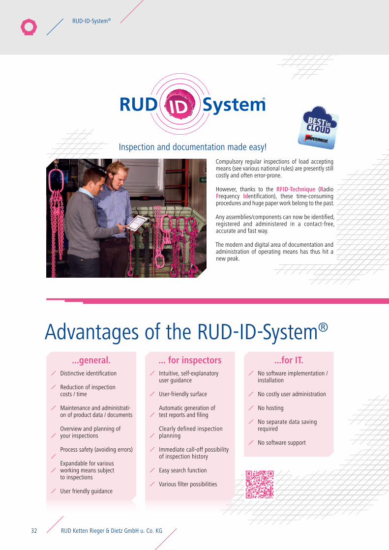
Advantages of the RUD-ID-System®
Inspection and documentation made easy!
...general. ... for inspectors ...for IT.Intuitive, self-explanatory user guidance
User-friendly surface
Automatic generation of test reports and filing
Clearly defined inspection planning
Immediate call-off possibility of inspection history
Easy search function
Various filter possibilities
Distinctive identification
Reduction of inspection costs / time
Maintenance and administrati-on of product data / documents
Overview and planning of your inspections
Process safety (avoiding errors)
Expandable for various working means subject to inspections
User friendly guidance
No software implementation / installation
No costly user administration
No hosting
No separate data saving required
No software support
Compulsory regular inspections of load accepting means (see various national rules) are presently still costly and often error-prone.
However, thanks to the RFID-Technique (Radio Frequency Identification), these time-consuming procedures and huge paper work belong to the past.
Any assemblies/components can now be identified, registered and administered in a contact-free, accurate and fast way.
The modern and digital area of documentation and administration of operating means has thus hit a new peak.
RUD Ketten Rieger & Dietz GmbH u. Co. KG32
RUD-ID-System®
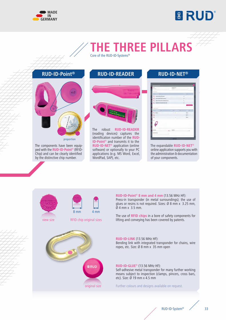
THE THREE PILLARS
RUD-ID-Point® RUD-ID-NET®RUD-ID-READER
RUD-ID-Point® 8 mm and 4 mm (13.56 MHz HF): Press-in transponder (in metal surroundings); the use of glues or resins is not required. Sizes: Ø 8 mm x 3.25 mm, Ø 4 mm x 3.5 mm.
The use of RFID chips in a bore of safety components for lifting and conveying has been covered by patents.
RUD-ID-GLUE® (13.56 MHz HF): Self-adhesive metal transponder for many further working means subject to inspection (clamps, pincers, cross bars, etc). Size: Ø 19 mm x 4.5 mm
Further colours and designs available on request.
RUD-ID-LINK (13.56 MHz HF): Bending link with integrated transponder for chains, wire ropes, etc. Size: Ø 8 mm x 35 mm open
The robust RUD-ID-READER (reading devices) captures the identification number of the RUD-ID-Point® and transmits it to the RUD-ID-NET® application (online software) or optionally to your PC applications (e.g. MS Word, Excel, WordPad, SAP), etc.
The components have been equip-ped with the RUD-ID-Point® (RFID-Chip) and can be clearly identified by the distinctive chip number.
The expandable RUD-ID-NET®
online application supports you with the administration & documentation of your components.
view size RFID chip original sizes
4 mm8 mm
original size
Core of the RUD-ID-Systems®
proportion
MADEIN
GERMANY
33RUD-ID-System®
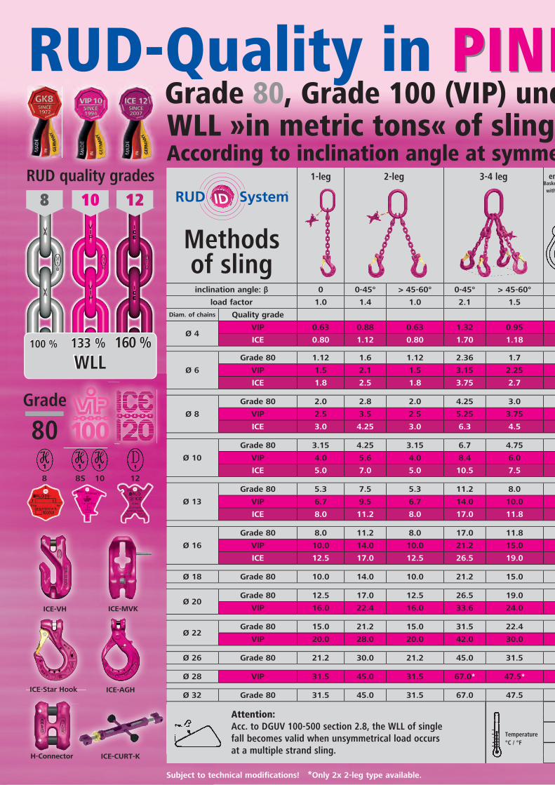
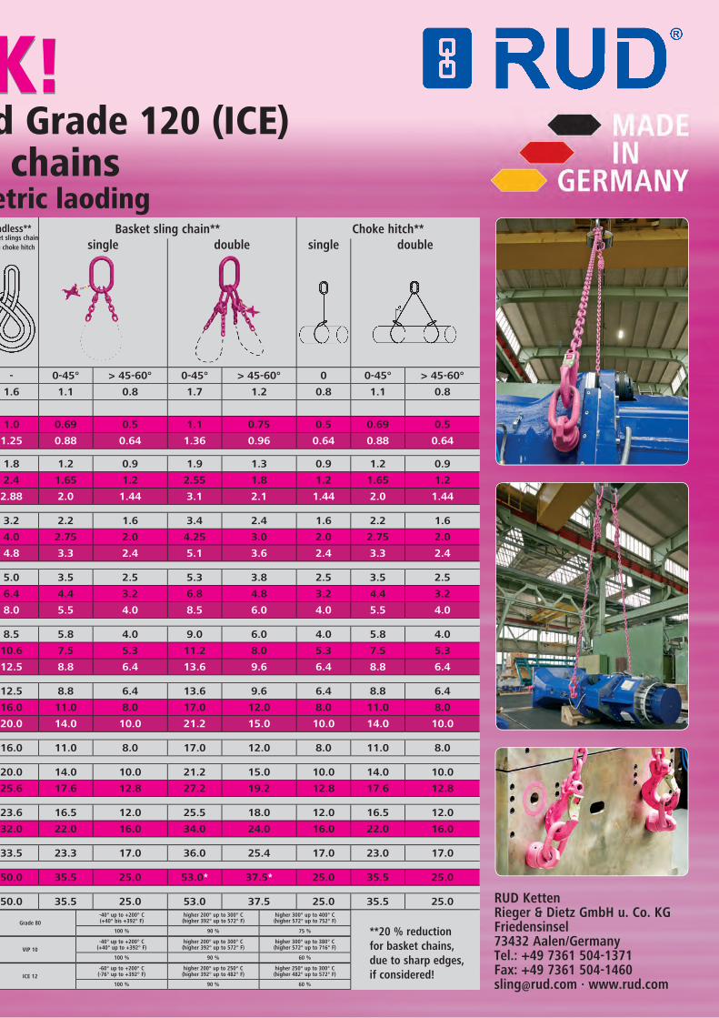
**20 % reduction for basket chains, due to sharp edges, if considered!
Temperature°C / °F
Attention:Acc. to DGUV 100-500 section 2.8, the WLL of single fall becomes valid when unsymmetrical load occurs at a multiple strand sling.
Methods of sling
1-leg 2-leg 3-4 leg Choke hitch**endless**Basket slings chain
with choke hitch singleBasket sling chain**
singledouble double
Grade 80-40° up to +200° C(+40° bis +392° F)
higher 200° up to 300° C(higher 392° up to 572° F)
higher 300° up to 400° C(higher 572° up to 752° F)
100 % 90 % 75 %
VIP 10-40° up to +200° C
(+40° up to +392° F)higher 200° up to 300° C(higher 392° up to 572° F)
higher 300° up to 380° C(higher 572° up to 716° F)
100 % 90 % 60 %
ICE 12-60° up to +200° C(-76° up to +392° F)
higher 200° up to 250° C(higher 392° up to 482° F)
higher 250° up to 300° C(higher 482° up to 572° F)
100 % 90 % 60 %
inclination angle: β 0 0-45° > 45-60° 0-45° > 45-60° - 0-45° > 45-60° 0-45° > 45-60° 0 0-45° > 45-60°
load factor 1.0 1.4 1.0 2.1 1.5 1.6 1.1 0.8 1.7 1.2 0.8 1.1 0.8
Diam. of chains Quality grade
Ø 4VIP 0.63 0.88 0.63 1.32 0.95 1.0 0.69 0.5 1.1 0.75 0.5 0.69 0.5
ICE 0.80 1.12 0.80 1.70 1.18 1.25 0.88 0.64 1.36 0.96 0.64 0.88 0.64
Ø 6
Grade 80 1.12 1.6 1.12 2.36 1.7 1.8 1.2 0.9 1.9 1.3 0.9 1.2 0.9
VIP 1.5 2.1 1.5 3.15 2.25 2.4 1.65 1.2 2.55 1.8 1.2 1.65 1.2
ICE 1.8 2.5 1.8 3.75 2.7 2.88 2.0 1.44 3.1 2.1 1.44 2.0 1.44
Ø 8
Grade 80 2.0 2.8 2.0 4.25 3.0 3.2 2.2 1.6 3.4 2.4 1.6 2.2 1.6
VIP 2.5 3.5 2.5 5.25 3.75 4.0 2.75 2.0 4.25 3.0 2.0 2.75 2.0
ICE 3.0 4.25 3.0 6.3 4.5 4.8 3.3 2.4 5.1 3.6 2.4 3.3 2.4
Ø 10
Grade 80 3.15 4.25 3.15 6.7 4.75 5.0 3.5 2.5 5.3 3.8 2.5 3.5 2.5
VIP 4.0 5.6 4.0 8.4 6.0 6.4 4.4 3.2 6.8 4.8 3.2 4.4 3.2
ICE 5.0 7.0 5.0 10.5 7.5 8.0 5.5 4.0 8.5 6.0 4.0 5.5 4.0
Ø 13
Grade 80 5.3 7.5 5.3 11.2 8.0 8.5 5.8 4.0 9.0 6.0 4.0 5.8 4.0
VIP 6.7 9.5 6.7 14.0 10.0 10.6 7.5 5.3 11.2 8.0 5.3 7.5 5.3
ICE 8.0 11.2 8.0 17.0 11.8 12.5 8.8 6.4 13.6 9.6 6.4 8.8 6.4
Ø 16
Grade 80 8.0 11.2 8.0 17.0 11.8 12.5 8.8 6.4 13.6 9.6 6.4 8.8 6.4
VIP 10.0 14.0 10.0 21.2 15.0 16.0 11.0 8.0 17.0 12.0 8.0 11.0 8.0
ICE 12.5 17.0 12.5 26.5 19.0 20.0 14.0 10.0 21.2 15.0 10.0 14.0 10.0
Ø 18 Grade 80 10.0 14.0 10.0 21.2 15.0 16.0 11.0 8.0 17.0 12.0 8.0 11.0 8.0
Ø 20Grade 80 12.5 17.0 12.5 26.5 19.0 20.0 14.0 10.0 21.2 15.0 10.0 14.0 10.0
VIP 16.0 22.4 16.0 33.6 24.0 25.6 17.6 12.8 27.2 19.2 12.8 17.6 12.8
Ø 22Grade 80 15.0 21.2 15.0 31.5 22.4 23.6 16.5 12.0 25.5 18.0 12.0 16.5 12.0
VIP 20.0 28.0 20.0 42.0 30.0 32.0 22.0 16.0 34.0 24.0 16.0 22.0 16.0
Ø 26 Grade 80 21.2 30.0 21.2 45.0 31.5 33.5 23.3 17.0 36.0 25.4 17.0 23.0 17.0
Ø 28 VIP 31.5 45.0 31.5 67.0* 47.5* 50.0 35.5 25.0 53.0* 37.5* 25.0 35.5 25.0
Ø 32 Grade 80 31.5 45.0 31.5 67.0 47.5 50.0 35.5 25.0 53.0 37.5 25.0 35.5 25.0
8 10 12
100
®
ICE-Star Hook ICE-AGH
ICE-CURT-KH-Connector
12
ICE-VH ICE-MVK
8 8S 10
Grade
80
RUD quality grades
100 % 133 % 160 % WLL
100 % 133 % 160 % WLL
RUD KettenRieger & Dietz GmbH u. Co. KGFriedensinsel73432 Aalen/GermanyTel.: +49 7361 504-1371Fax: +49 7361 [email protected] · www.rud.com
Subject to technical modifications! *Only 2x 2-leg type available.
PINK!RUD-Quality in PINK! Grade 80, Grade 100 (VIP) und Grade 120 (ICE)
WLL »in metric tons« of sling chains According to inclination angle at symmetric laoding
Engineered and madein the heart of Europe!
Tradition in Dynamic Innovation
RUD KettenRieger & Dietz GmbH u. Co. KGFriedensinsel73432 Aalen / GermanyTel. +49 7361 504-1371 / Fax. +49 7361 [email protected] / www.rud.com
Overview – Lifting- and lashing points PSA
Selection Chart – product features
WLL table – lifting points for bolting
Dimensioning of lifting points
ICE-Bolt PINK overheat indicator
Why ball bearing?
Bad Points
Good Points
VIP Load ring for bolting Load ring for bolting stainless steel
ICE Load ring for bolting SUPER ROTATION®
02
04
06
08
10
12
14
16
18ICE-LBG-SR
VLBG LBG-RS 24
Page
RUD-ID-System® – Inspection and Documentation 32
CONTENTSIntroduction ICE-LBG-SR VLBG LBG-RS RUD-ID-System®
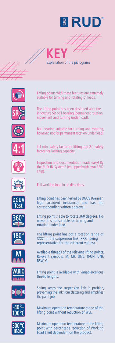
Lifting points with these features are extremely suitable for turning and rotating of loads.
Ball bearing suitable for turning and rotating, however, not for permanent rotation under load!
4:1 min. safety factor for lifting and 2:1 safety factor for lashing capacity.
The lifting point has been designed with the innovative SR-ball-bearing (permanent rotation movement and turning under load).
RUDID
4:1
360°
180°
M
300°Cmax.
-40°–100°C
SR
Inspection and documentation made easy! By the RUD-ID-System® (equipped with own RFID chip).
Lifting point is able to rotate 360 degrees. Ho-wever it is not suitable for turning and rotation under load.
The lifting point has got a rotation range of XXX° in the suspension link (XXX° being representative for the different values).
Available threads of the relevant lifting points. Relevant symbols: M, MF, UNC, 8-UN, UNF, BSW, G.
Spring keeps the suspension link in position, preventing the link from clattering and simplifies the paint job.
Maximum operation temperature range of the lifting point without reduction of WLL.
Maximum operation temperature of the lifting point with percentage reduction of Working Load Limit dependent on the product.
Full working load in all directions.
Lifting point is available with variable/various thread lengths.
Lifting point has been tested by DGUV (German legal accident insurance) and has the corresoponding written approval.
DGUVTest
VARIO
Explanation of the pictogramsKEY