ENERGY TEST - SPY SYSTEM - rieste.at · Il tipo di batteria e la data di produzione sono indicati...
6
APPARECCHIO DI EMERGENZA EMERGENCY LUMINAIRE STEP ENERGY TEST - SPY SYSTEM IP40 ISTRUZIONI PER L'USO L'INSTALLAZIONE E INSTALLATION AND USE INSTRUCTIONS I UK INSTALLAZIONE: 1) Rimuovere il diffusore facendo leva con dei cacciaviti nei punti indicati; 2) Sganciare il riflettore dalla base facendo leva con un cacciavite nel punto indicato; 3) Forare se necessario uno dei tre possibili ingressi laterali per il cavo di alimentazione ed applicare la base al muro tramite gli appositi fori per il fissaggio; 4) Eseguire i cablaggi elettrici (Fig.3-4-5); 5) Riagganciare il riflettore alla base facendo scattare il dente; 6) Riagganciare il diffusore alla base facendo scattare i denti. Attenzione: In caso di installazione a parete il prodotto deve essere disposto con i led verso l’alto. BATTERIE: Sostituire la batteria ogni quattro anni o quando l'autonomia non è più quella nominale. Il tipo di batteria e la data di produzione sono indicati con una marcatura sulla batteria (Fig.1). Inoltre c'è uno spazio da riempire a cura dell'installatore con la data di entrata in funzione. Attenzione: Le batterie al Ni-Cd e Ni-MH sono inizialmente scariche, la prima ricarica deve durare almeno 48h. INSTALLATION: 1) Remove the transparent cover pushing with a screwdriver; 2) Unhook the body of the lamp from the base with a screwdriver; 3) Drill if necessary one of the three possible entries for the power supply cable and fix the base to the wall using the holes on the base; 4) Make the electric connections (Fig.3-4-5); 5) Hook the body to the base making release the tooth; 6) Hook the transparent cover to the base making release the tooth. Warning: In case of wall mounting the product must be positioned with the leds up. BATTERIES: It is recommended to substitute each battery every four years or when the nominal autonomy is not guaranteed. The model and the date of production of the battery are written on it. Fill the field with the date of the first starting (Fig.1). Warning: The Ni-Cd and Ni-MH batteries are sold uncharged: the first charge must be 48h long. GENERAL CHARACTERISTICS: - Indicator green Led for the presence of the power supply. - Indicatore red Led for the warnings signallings. - Operation with rechargeable Ni-Cd and NiMH batteries. - Constant current electronic device for the charge of the battery. - Electrical protection device for the excessive discharge of battery. - Possibility to be put in the stand-by mode by remote control Commander (optional) - Possibility to put a green signal label . - Plastic body in accordance with the rules in force. CARATTERISTICHE GENERALI: - Led spia verde per presenza rete. - Led spia rosso per segnalazione anomalie. - Funzionamento con batterie ricaricabili al Ni-Cd e al NiMH. - Dispositivo di ricarica delle batterie a corrente costante. - Dispositivo di protezione contro la scarica eccessiva della batteria. - Possibilità di messa in stato di riposo tramite il comando remoto Commander (opzionale). - Possibilità di applicare dei pittogrammi di segnalazione. - Corpo in materiale plastico conforme alle normative vigenti. EN 60598-1 EN 60598-2-22 2002/95/CE RoHS Compliant MADE IN ITALY 230 Vac - 50 Hz FUNZIONI DI TEST: - La lampada esegue due tipi di test temporizzati: il test funzionale e il test di autonomia. I test funzionale e di autonomia possono essere effettuati anche manualmente con il Commander quando la batteria è in ricarica di mantenimento. - Tutti i test manuali vengono eseguiti se ci sono le condizioni ambientali idonee di luce esterna. Se le condizioni esterne non sono idonee il test viene rinviato al primo verificarsi delle condizioni idonee. Durante il tempo di attesa il led verde lampeggia per segnalare che la lampada sta aspettando di potere compiere i test. Test funzionale: viene effettuato ogni 15 giorni e consiste nella accensione della lampada fluorescente per una durata di 5 secondi. Per attivare il test funzionale manuale premere una volta il Commander ON (effettuare una pressione breve della durata non superiore a 2 secondi) Test di autonomia: viene effettuato ogni 90 giorni e consiste nella completa scarica della batteria. P e il test di autonomia premere una volta il Commander ON (effettuare una pressione lunga della durata non inferiore a 5 secondi). Disabilitazione dei test: tutti i test temporizzati possono essere inibiti tramite la pressione di un tasto del Commander OFF, ad una seconda pressione del tasto ON i test temporizzati verranno riabilitati. er far partir TEST FUNCTIONS: -The lamp makes two kinds of deliberate time tests: the functional test and the duration test. The functional test and the duration test can be made also in the manual way with the use of the Commander in the normal charge mode. -All the manual tests can be made only if there is the good ambient condition of external light. If the external conditions aren't good the test is postponed to the first coming of the good conditions. In the time of waiting the green led flashes to indicate that the lamp is waiting for the test. The functional test: is done every 15 days and consists in the lighting of the fluorescent lamp for a duration of 5 seconds. To start the manual functional test push one time the Commander ON (make a short push no more than 2 seconds) The duration test: is done every 90 days and consists in the complete discharge of the battery. To start the duration test push one time the Commander ON (make a long push no less than 5 seconds). Disabilitation of the tests: all deliberate time tests can be disabled with a pushing of the button of Commander OFF, with a second pushing of the Commander ON deliberate time tests will be enabled. Linergy Batteria Ricaricabile / Rechargeable Battery Entrata in funzione / Coming in operation......................... mm.aaaa 6V Ni-Cd XXX C2500*5 CONDIZIONI DI GARANZIA / WARRANTY CONDITION La garanzia sugli apparecchi di emergenza è di 2 anni dalla data di vendita. La garanzia decade se il prodotto è stato manomesso o riparato da personale non autorizzato LINERGY. The warranty on the emergency luminaire is 2 years from the sales date. The warranty voids if the product has been mishandled or repaired by personnel not authorized by LINERGY. Fig.1 1. 1. 2. 3. 3. 3. MAINS SUPPLY ON, NO WARNING BATTERY IN FAST CHARGE TEST DISABLED, INHIBIT LUMINAIRE BATTERY FAULT WARNING LUMINAIRE SEGNALETICA LED / LED SIGNALLING VERDE ACCESO FISSO / GREEN ON PRESENZA RETE, NESSUNA ANOMALIA BATTERIA IN RICARICA FAST TEST IN CORSO / TEST IN PROGRESS TEST DISABILITATI, LAMPADA INIBITA GUASTO BATTERIA ANOMALIA LAMPADA VERDE LAMPEGGIANTE VELOCE / GREEN FAST FLASHING VERDE LAMPEGGIANTE LENTO / GREEN SLOW FLASHING ROSSO LAMPEGGIANTE LENTO / RED SLOW FLASHING ROSSO LAMPEGGIANTE VELOCE / RED FAST FLASHING ROSSO ACCESO FISSO / RED ON ALIMENTAZIONE/ POWER SUPPLY POTENZA ASSORBITA/ POWER ABSORPTION GRADO DI PROTEZIONE/ PROTECTION DEGREE CLASSE DI ISOLAMENTO/ INSULATING CLASS SEZIONE DEL CAVO/ WIRE DIAMETER CARATTERISTICHE TECNICHE/TECHNICAL CHARACTERISTICS 230Vac - 50Hz 4VA IP 40 II 0,5 - 5mm 2
Transcript of ENERGY TEST - SPY SYSTEM - rieste.at · Il tipo di batteria e la data di produzione sono indicati...

APPARECCHIO DI EMERGENZAEMERGENCY LUMINAIRE
STEPENERGY TEST - SPY SYSTEM
IP40ISTRUZIONI PER L'USOL'INSTALLAZIONE E
INSTALLATION AND USE INSTRUCTIONS
I
UK
INSTALLAZIONE:1) Rimuovere il diffusore facendo leva con dei cacciaviti nei punti indicati;2) Sganciare il riflettore dalla base facendo leva con un cacciavite nel punto indicato; 3) Forare se necessario uno dei tre possibili ingressi laterali per il cavo di alimentazione ed applicare la base al muro tramite gli appositi fori per il fissaggio; 4) Eseguire i cablaggi elettrici (Fig.3-4-5); 5) Riagganciare il riflettore alla base facendo scattare il dente;6) Riagganciare il diffusore alla base facendo scattare i denti.Attenzione: In caso di installazione a parete il prodotto deve essere disposto con i led verso l’alto.BATTERIE:Sostituire la batteria ogni quattro anni o quando l'autonomia non è più quella nominale. Il tipo di batteria e la data di produzione sono indicati con una marcatura sulla batteria (Fig.1). Inoltre c'è uno spazio da riempire a cura dell'installatore con la data di entrata in funzione.Attenzione: Le batterie al Ni-Cd e Ni-MH sono inizialmente scariche, la prima ricarica deve durare almeno 48h.
INSTALLATION:1) Remove the transparent cover pushing with a screwdriver;2) Unhook the body of the lamp from the base with a screwdriver; 3) Drill if necessary one of the three possible entries for the power supply cable and fix the base to the wall using the holes on the base;4) Make the electric connections (Fig.3-4-5); 5) Hook the body to the base making release the tooth;6) Hook the transparent cover to the base making release the tooth.Warning: In case of wall mounting the product must be positioned with the leds up.BATTERIES: It is recommended to substitute each battery every four years or when the nominal autonomy is not guaranteed. The model and the date of production of the battery are written on it. Fill the field with the date of the first starting (Fig.1).Warning: The Ni-Cd and Ni-MH batteries are sold uncharged: the first charge must be 48h long.
GENERAL CHARACTERISTICS:- Indicator green Led for the presence of the power supply.- Indicatore red Led for the warnings signallings.- Operation with rechargeable Ni-Cd and NiMH batteries.- Constant current electronic device for the charge of the battery.- Electrical protection device for the excessive discharge of battery.- Possibility to be put in the stand-by mode by remote control Commander (optional)- Possibility to put a green signal label .- Plastic body in accordance with the rules in force.
CARATTERISTICHE GENERALI:- Led spia verde per presenza rete.- Led spia rosso per segnalazione anomalie.- Funzionamento con batterie ricaricabili al Ni-Cd e al NiMH.- Dispositivo di ricarica delle batterie a corrente costante.- Dispositivo di protezione contro la scarica eccessiva della batteria.- Possibilità di messa in stato di riposo tramite il comando remoto Commander (opzionale).- Possibilità di applicare dei pittogrammi di segnalazione.- Corpo in materiale plastico conforme alle normative vigenti.
EN 60598-1 EN 60598-2-22 2002/95/CE RoHS Compliant
MADE IN ITALY230 Vac - 50 Hz
FUNZIONI DI TEST:- La lampada esegue due tipi di test temporizzati: il test funzionale e il test di autonomia. I test funzionale e di autonomia possono essere effettuati anche manualmente con il Commander quando la batteria è in ricarica di mantenimento.- Tutti i test manuali vengono eseguiti se ci sono le condizioni ambientali idonee di luce esterna. Se le condizioni esterne non sono idonee il test viene rinviato al primo verificarsi delle condizioni idonee. Durante il tempo di attesa il led verde lampeggia per segnalare che la lampada sta aspettando di potere compiere i test.Test funzionale: viene effettuato ogni 15 giorni e consiste nella accensione della lampada fluorescente per una durata di 5 secondi. Per attivare il test funzionale manuale premere una volta il Commander ON (effettuare una pressione breve della durata non superiore a 2 secondi)Test di autonomia: viene effettuato ogni 90 giorni e consiste nella completa scarica della batteria. P e il test di autonomia premere una volta il Commander ON (effettuare una pressione lunga della durata non inferiore a 5 secondi).Disabilitazione dei test: tutti i test temporizzati possono essere inibiti tramite la pressione di un tasto del Commander OFF, ad una seconda pressione del tasto ON i test temporizzati verranno riabilitati.
er far partir
TEST FUNCTIONS:-The lamp makes two kinds of deliberate time tests: the functional test and the duration test. The functional test and the duration test can be made also in the manual way with the use of the Commander in the normal charge mode.-All the manual tests can be made only if there is the good ambient condition of external light. If the external conditions aren't good the test is postponed to the first coming of the good conditions. In the time of waiting the green led flashes to indicate that the lamp is waiting for the test.The functional test: is done every 15 days and consists in the lighting of the fluorescent lamp for a duration of 5 seconds. To start the manual functional test push one time the Commander ON (make a short push no more than 2 seconds)The duration test: is done every 90 days and consists in the complete discharge of the battery. To start the duration test push one time the Commander ON (make a long push no less than 5 seconds).Disabilitation of the tests: all deliberate time tests can be disabled with a pushing of the button of Commander OFF, with a second pushing of the Commander ON deliberate time tests will be enabled.
LinergyBatteria Ricaricabile / Rechargeable BatteryEntrata in funzione / Coming in operation.........................
mm.aaaa 6V Ni-Cd XXX C2500*5
CONDIZIONI DI GARANZIA / WARRANTY CONDITION
La garanzia sugli apparecchi di emergenza è di 2 anni dalla data di vendita. La garanzia decade se il prodotto è stato manomesso o riparato da personale non autorizzato LINERGY.The warranty on the emergency luminaire is 2 years from the sales date. The warranty voids if the product has been mishandled or repaired by personnel not authorized by LINERGY.
Fig.1
1.
1.
2.
3.
3. 3.
MAINS SUPPLY ON, NO WARNING
BATTERY IN FAST CHARGE
TEST DISABLED, INHIBIT LUMINAIRE
BATTERY FAULT
WARNING LUMINAIRE
SEGNALETICA LED / LED SIGNALLINGVERDE ACCESO FISSO / GREEN ON
PRESENZA RETE, NESSUNA ANOMALIA
BATTERIA IN RICARICA FAST
TEST IN CORSO / TEST IN PROGRESS
TEST DISABILITATI, LAMPADA INIBITA
GUASTO BATTERIA
ANOMALIA LAMPADA
VERDE LAMPEGGIANTE VELOCE / GREEN FAST FLASHING
VERDE LAMPEGGIANTE LENTO / GREEN SLOW FLASHING
ROSSO LAMPEGGIANTE LENTO / RED SLOW FLASHING
ROSSO LAMPEGGIANTE VELOCE / RED FAST FLASHING
ROSSO ACCESO FISSO / RED ON
ALIMENTAZIONE/ POWER SUPPLY
POTENZA ASSORBITA/ POWER ABSORPTION
GRADO DI PROTEZIONE/ PROTECTION DEGREE
CLASSE DI ISOLAMENTO/ INSULATING CLASS
SEZIONE DEL CAVO/ WIRE DIAMETER
CARATTERISTICHE TECNICHE/TECHNICAL CHARACTERISTICS
230Vac - 50Hz
4VA
IP 40
II
0,5 - 5mm2
BA
230Vac
COMMANDER
PresenzaRETE
AbilitazioneEmergenza
COMMANDER
ON
OFF
ABILITAZIONE
REST MODE(OPTIONAL)
L N
L N
L N
SE SA B A SE SA B A
ENERGY TEST - AUTODIAGNOSI LOCALE / SELF TESTINIBIZIONE / INHIBITION
ENERGY TEST - AUTODIAGNOSI LOCALE / SELF TESTREST MODE CON COMMANDER
- NON PERMANENTE (SE) /NON MAINTAINED - PERMANENTE (SA) / MAINTAINED
Fig. 5a
230Vac50Hz
SE
- NON PERMANENTE SE / NON MAINTAINED
Fig .4a
230Vac50Hz
BA
230Vac
COMMANDER
PresenzaRETE
AbilitazioneEmergenza
COMMANDER
ON
OFF
ABILITAZIONE
REST MODE(OPTIONAL)
- PERMANENTE SA / MAINTAINED
230Vac50Hz
SE SA
NOTE:Non collegare il ponticello A-B se si utilizza il Commander.Do not short the A B terminals if you are using the Commander.
NOTE:Non collegare il ponticello A-B se si utilizza il Commander.Do not short the A B terminals if you are using the Commander.
INSTALLAZIONE CON COMMANDER - REST MODEINSTALLATION WITH COMMANDER
SESABA
MODO DI RIPOSOREST MODE
J9
BA
PresenzaRETE
AbilitazioneEmergenza
COMMANDER
ON
OFF
ABILITAZIONE
SPOSTARE LO SWITCH J9 COME INDICATO IN FIGURA.
Dopo aver spostato lo switch J9resettare il microprocessore con le seguenti operazioni:1. Scollegare la batteria 2. Cortocircuitare i pin del connettore J2 con un giravite3. Ricollegare la batteria.
J2
L’installazione con Commanderpermette l’inibizione a distanza degli apparecchi collegati nonché effettuare dei test manuali.(vedi Funzioni di Test pag.1)
The installation with Commanderallows the remote inhibition of the connected luminairesand the manual tests. (see Test functions pag.1)
After moving the switch J9Reset the microprocessor in the following way:1. Disconnect the battery2. Short circuit the pins of the connector J2 with the screw3. Connect the battery.
MOVE THE SWITCH J9 AS SHOWN IN THE PICTURE.
Fig. 8
Fig. 9
Fig. 3
230Vac50Hz
SE
Fig .5
230Vac50Hz 230Vac
50Hz
SE SA
L N
L NL N
INTERRUTTORE ESTERNO
EXTERNALTEST BUTTON
INTERRUTTORE ESTERNO
EXTERNALTEST BUTTON
N.B.Mai collegare la tensione di rete sui morsettiA-B, la scheda elettronica si danneggia.
A-B Interruttore di inibizione, chiuderlo con un pontea filo per abilitare l’emergenza.
N.B.Never connect the main supply to the A-B pins.The electronic circuit breaks down.
A-B Inhibition switch, close it with a short wire to enable the emergency.
SE SESA SA B B A A
Fig .4
L N
L N
L N
SE SA B ASE SA B A
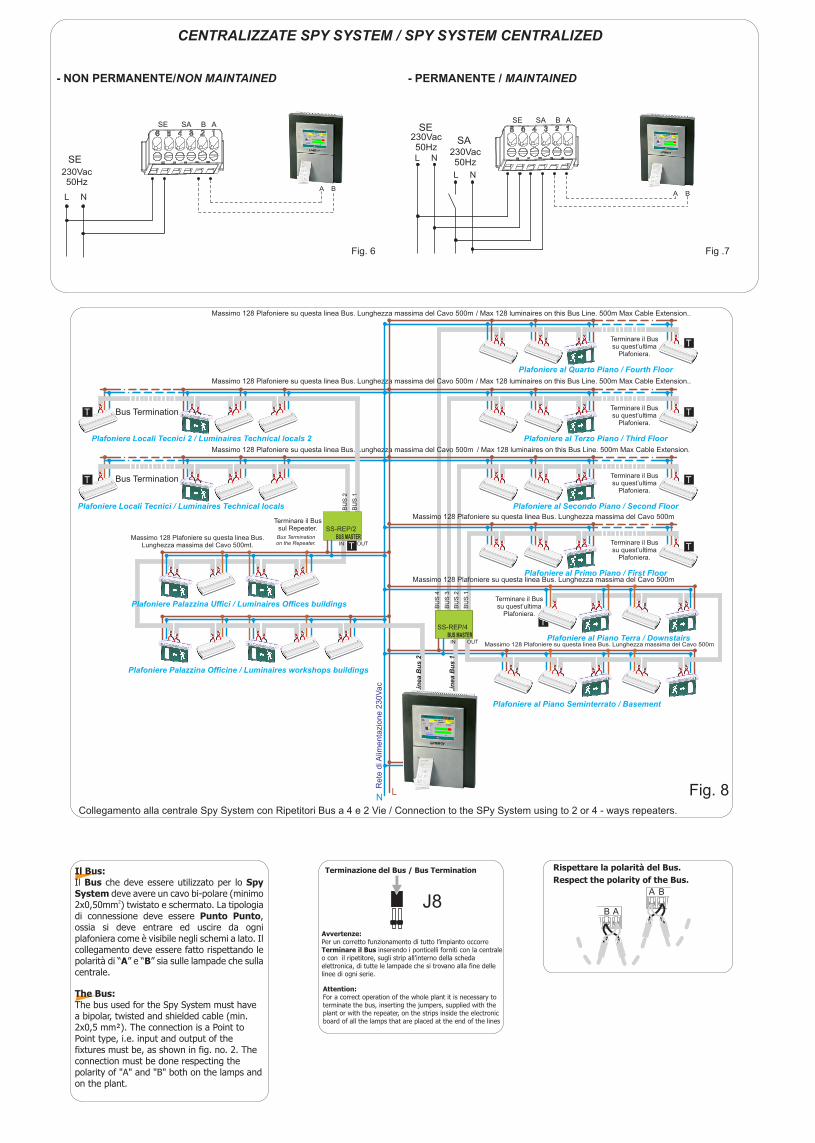
CENTRALIZZATE SPY SYSTEM / SPY SYSTEM CENTRALIZED
Fig. 6
230Vac50Hz
SE
BA
- NON PERMANENTE/NON MAINTAINED
Fig .7
230Vac50Hz
BA
- PERMANENTE / MAINTAINED
230Vac50Hz
SE
SA
/ Max 128 luminaires on this Bus Line. 500m Max Cable Extension..
/ Max 128 luminaires on this Bus Line. 500m Max Cable Extension.
/ Max 128 luminaires on this Bus Line. 500m Max Cable Extension..Massimo 128 Plafoniere su questa linea Bus. Lunghezza massima del Cavo 500m
Massimo 128 Plafoniere su questa linea Bus. Lunghezza massima del Cavo 500m
Massimo 128 Plafoniere su questa linea Bus. Lunghezza massima del Cavo 500m
Massimo 128 Plafoniere su questa linea Bus. Lunghezza massima del Cavo 500m
Massimo 128 Plafoniere su questa linea Bus. Lunghezza massima del Cavo 500m
Massimo 128 Plafoniere su questa linea Bus. Lunghezza massima del Cavo 500m
Bus Termination
Bus Termination
Bus Terminationon the Repeater.
Re
te d
i Alim
en
tazio
ne
23
0V
ac
LN
Massimo 128 Plafoniere su questa linea Bus.Lunghezza massima del Cavo 500mt.
Plafoniere Palazzina Uffici / Luminaires Offices buildings
Plafoniere Palazzina Officine / Luminaires workshops buildings
Plafoniere Locali Tecnici / Luminaires Technical locals
Plafoniere Locali Tecnici 2 / Luminaires Technical locals 2
Terminare il Bussul Repeater.
T
T
T
Collegamento alla centrale Spy System con Ripetitori Bus a 4 e 2 Vie / Connection to the SPy System using to 2 or 4 - ways repeaters.
Lin
ea
Bu
s 2
Plafoniere al Piano Terra / Downstairs
Plafoniere al Piano Seminterrato / Basement
Plafoniere al Primo Piano / First Floor
Plafoniere al Secondo Piano / Second Floor
Plafoniere al Terzo Piano / Third Floor
Plafoniere al Quarto Piano / Fourth Floor
Terminare il Bussu quest’ultima
Plafoniera.
Terminare il Bussu quest’ultima
Plafoniera.
Terminare il Bussu quest’ultima
Plafoniera.
Terminare il Bussu quest’ultima
Plafoniera.
Terminare il Bussu quest’ultima
Plafoniera.
T
T
T
T
T
Fig. 8
Lin
ea
Bu
s 1
BU
S 4
BU
S 3
BU
S 2
BU
S 1
SS-REP/4
IN OUTBUS MASTER
SS-REP/2
IN OUTBUS MASTER
BU
S 2
BU
S 1
T
The Bus:The bus used for the Spy System must have a bipolar, twisted and shielded cable (min. 2x0,5 mm²). The connection is a Point to Point type, i.e. input and output of the fixtures must be, as shown in fig. no. 2. The connection must be done respecting the polarity of "A" and "B" both on the lamps and on the plant.
Respect the polarity of the Bus.
Attention:For a correct operation of the whole plant it is necessary to terminate the bus, inserting the jumpers, supplied with the plant or with the repeater, on the strips inside the electronic board of all the lamps that are placed at the end of the lines
Bus TerminationTerminazione del Bus /Il Bus:Il Bus che deve essere utilizzato per lo Spy System deve avere un cavo bi-polare (minimo
22x0,50mm ) twistato e schermato. La tipologia di connessione deve essere Punto Punto, ossia si deve entrare ed uscire da ogni plafoniera come è visibile negli schemi a lato. Il collegamento deve essere fatto rispettando le polarità di “A” e “B” sia sulle lampade che sulla centrale.
B
B
A
A
Rispettare la polarità del Bus.
J8
Avvertenze:Per un corretto funzionamento di tutto l’impianto occorre Terminare il Bus inserendo i ponticelli forniti con la centrale o con il ripetitore, sugli strip all’interno della scheda elettronica, di tutte le lampade che si trovano alla fine delle linee di ogni serie.
LINERGY S.R.L. - via A. De Gasperi 9 - Acquaviva Picena (AP) - ITALY - tel.0735.5974 - fax 0735.597474 - www.linergy.it - [email protected] - ISTSTET - Ver. 7.4
CONDIZIONI DI GARANZIA / WARRANTY CONDITION
La garanzia sugli apparecchi di emergenza è di 2 anni dalla data di vendita. La garanzia decade se il prodotto è stato manomesso o riparato da personale non autorizzato LINERGY.The warranty on the emergency luminaire is 2 years from the sales date. The warranty voids if the product has been mishandled or repaired by personnel not authorized by LINERGY.
Il cassonetto barrato sull’apparecchio specifica che il prodotto deve essere consegnato ai centri di raccolta autorizzati per un corretto smaltimento. Rivolgersi all’ufficio competente del proprio ente locale per informazioni sulla raccolta e sui termini di legge.The crossed out waste bin symbol indicates that the product should be taken to an authorized waste collection centre which can dispose of it properly. For information on waste collection centres and on current waste disposal legislation, please contact your local waste disposal authority.
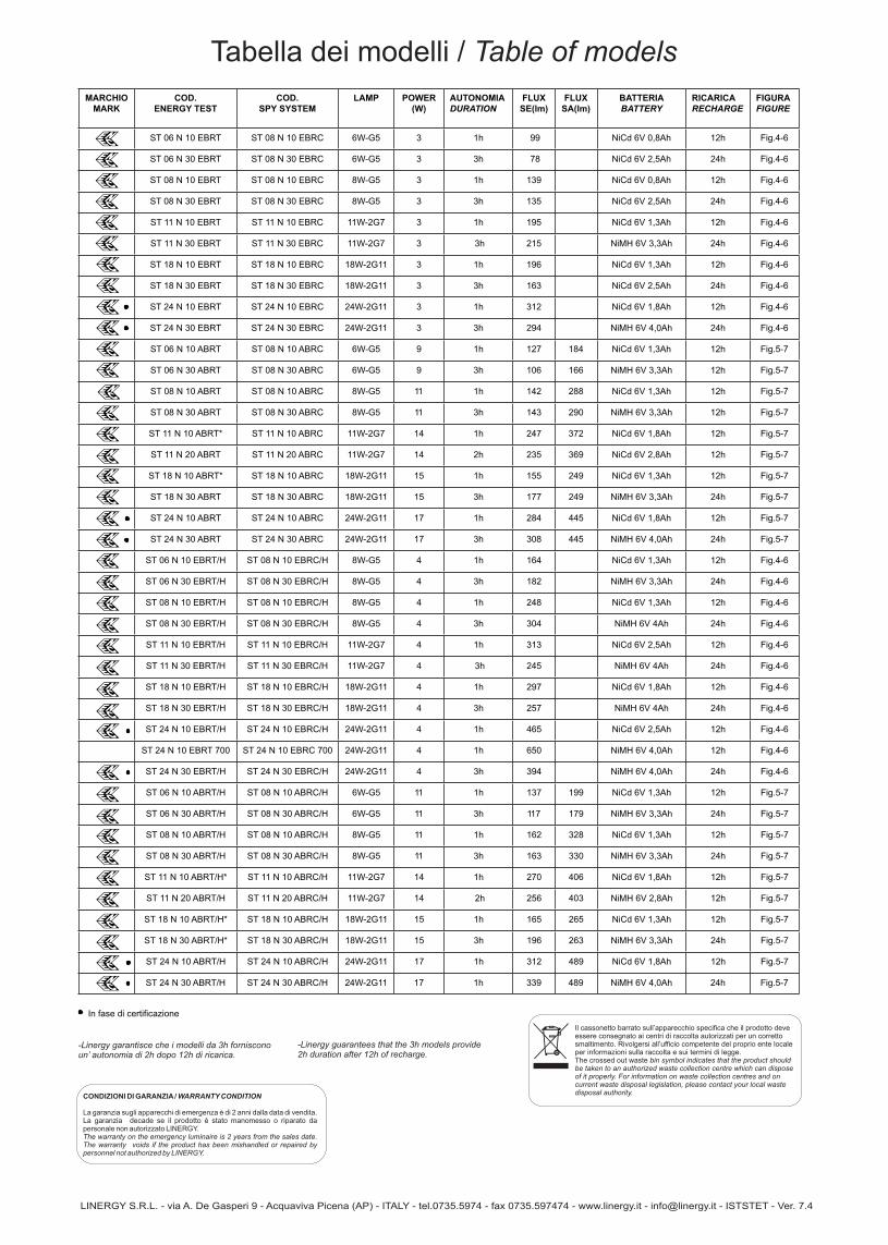
MARCHIOMARK
COD. ENERGY TEST
COD. SPY SYSTEM
LAMP POWER(W)
AUTONOMIADURATION
FLUX SE(lm)
FLUX SA(lm)
BATTERIABATTERY
RICARICARECHARGE
FIGURAFIGURE
ST 06 N 10 EBRT ST 08 N 10 EBRC 6W-G5 3 1h 99 NiCd 6V 0,8Ah 12h Fig.4-6
ST 06 N 30 EBRT ST 08 N 30 EBRC 6W-G5 3 3h 78 NiCd 6V 2,5Ah 24h Fig.4-6
ST 08 N 10 EBRT ST 08 N 10 EBRC 8W-G5 3 1h 139 NiCd 6V 0,8Ah 12h Fig.4-6
ST 08 N 30 EBRT ST 08 N 30 EBRC 8W-G5 3 3h 135 NiCd 6V 2,5Ah 24h Fig.4-6
ST 11 N 10 EBRT ST 11 N 10 EBRC 11W-2G7 3 1h 195 NiCd 6V 1,3Ah 12h Fig.4-6
ST 11 N 30 EBRT ST 11 N 30 EBRC 11W-2G7 3 3h 215 NiMH 6V 3,3Ah 24h Fig.4-6
ST 18 N 10 EBRT ST 18 N 10 EBRC 18W-2G11 3 1h 196 NiCd 6V 1,3Ah 12h Fig.4-6
ST 18 N 30 EBRT ST 18 N 30 EBRC 18W-2G11 3 3h 163 NiCd 6V 2,5Ah 24h Fig.4-6
ST 24 N 10 EBRT ST 24 N 10 EBRC 24W-2G11 3 1h 312 NiCd 6V 1,8Ah 12h Fig.4-6
ST 24 N 30 EBRT ST 24 N 30 EBRC 24W-2G11 3 3h 294 NiMH 6V 4,0Ah 24h Fig.4-6
ST 06 N 10 ABRT ST 08 N 10 ABRC 6W-G5 9 1h 127 184 NiCd 6V 1,3Ah 12h Fig.5-7
ST 06 N 30 ABRT ST 08 N 30 ABRC 6W-G5 9 3h 106 166 NiMH 6V 3,3Ah 12h Fig.5-7
ST 08 N 10 ABRT ST 08 N 10 ABRC 8W-G5 11 1h 142 288 NiCd 6V 1,3Ah 12h Fig.5-7
ST 08 N 30 ABRT ST 08 N 30 ABRC 8W-G5 11 3h 143 290 NiMH 6V 3,3Ah 12h Fig.5-7
ST 11 N 10 ABRT* ST 11 N 10 ABRC 11W-2G7 14 1h 247 372 NiCd 6V 1,8Ah 12h Fig.5-7
ST 11 N 20 ABRT ST 11 N 20 ABRC 11W-2G7 14 2h 235 369 NiCd 6V 2,8Ah 12h Fig.5-7
ST 18 N 10 ABRT* ST 18 N 10 ABRC 18W-2G11 15 1h 155 249 NiCd 6V 1,3Ah 12h Fig.5-7
ST 18 N 30 ABRT ST 18 N 30 ABRC 18W-2G11 15 3h 177 249 NiMH 6V 3,3Ah 24h Fig.5-7
ST 24 N 10 ABRT ST 24 N 10 ABRC 24W-2G11 17 1h 284 445 NiCd 6V 1,8Ah 12h Fig.5-7
ST 24 N 30 ABRT ST 24 N 30 ABRC 24W-2G11 17 3h 308 445 NiMH 6V 4,0Ah 24h Fig.5-7
ST 06 N 10 EBRT/H ST 08 N 10 EBRC/H 8W-G5 4 1h 164 NiCd 6V 1,3Ah 12h Fig.4-6
ST 06 N 30 EBRT/H ST 08 N 30 EBRC/H 8W-G5 4 3h 182 NiMH 6V 3,3Ah 24h Fig.4-6
ST 08 N 10 EBRT/H ST 08 N 10 EBRC/H 8W-G5 4 1h 248 NiCd 6V 1,3Ah 12h Fig.4-6
ST 08 N 30 EBRT/H ST 08 N 30 EBRC/H 8W-G5 4 3h 304 NiMH 6V 4Ah 24h Fig.4-6
ST 11 N 10 EBRT/H ST 11 N 10 EBRC/H 11W-2G7 4 1h 313 NiCd 6V 2,5Ah 12h Fig.4-6
ST 11 N 30 EBRT/H ST 11 N 30 EBRC/H 11W-2G7 4 3h 245 NiMH 6V 4Ah 24h Fig.4-6
ST 18 N 10 EBRT/H ST 18 N 10 EBRC/H 18W-2G11 4 1h 297 NiCd 6V 1,8Ah 12h Fig.4-6
ST 18 N 30 EBRT/H ST 18 N 30 EBRC/H 18W-2G11 4 3h 257 NiMH 6V 4Ah 24h Fig.4-6
ST 24 N 10 EBRT/H ST 24 N 10 EBRC/H 24W-2G11 4 1h 465 NiCd 6V 2,5Ah 12h Fig.4-6
ST 24 N 10 EBRT 700 ST 24 N 10 EBRC 700 24W-2G11 4 1h 650 NiMH 6V 4,0Ah 12h Fig.4-6
ST 24 N 30 EBRT/H ST 24 N 30 EBRC/H 24W-2G11 4 3h 394 NiMH 6V 4,0Ah 24h Fig.4-6
ST 06 N 10 ABRT/H ST 08 N 10 ABRC/H 6W-G5 11 1h 137 199 NiCd 6V 1,3Ah 12h Fig.5-7
ST 06 N 30 ABRT/H ST 08 N 30 ABRC/H 6W-G5 11 3h 117 179 NiMH 6V 3,3Ah 24h Fig.5-7
ST 08 N 10 ABRT/H ST 08 N 10 ABRC/H 8W-G5 11 1h 162 328 NiCd 6V 1,3Ah 12h Fig.5-7
ST 08 N 30 ABRT/H ST 08 N 30 ABRC/H 8W-G5 11 3h 163 330 NiMH 6V 3,3Ah 24h Fig.5-7
ST 11 N 10 ABRT/H* ST 11 N 10 ABRC/H 11W-2G7 14 1h 270 406 NiCd 6V 1,8Ah 12h Fig.5-7
ST 11 N 20 ABRT/H ST 11 N 20 ABRC/H 11W-2G7 14 2h 256 403 NiMH 6V 2,8Ah 12h Fig.5-7
ST 18 N 10 ABRT/H* ST 18 N 10 ABRC/H 18W-2G11 15 1h 165 265 NiCd 6V 1,3Ah 12h Fig.5-7
ST 18 N 30 ABRT/H* ST 18 N 30 ABRC/H 18W-2G11 15 3h 196 263 NiMH 6V 3,3Ah 24h Fig.5-7
ST 24 N 10 ABRT/H ST 24 N 10 ABRC/H 24W-2G11 17 1h 312 489 NiCd 6V 1,8Ah 12h Fig.5-7
ST 24 N 30 ABRT/H ST 24 N 30 ABRC/H 24W-2G11 17 1h 339 489 NiMH 6V 4,0Ah 24h Fig.5-7
In fase di certificazione
Tabella dei modelli / Table of models
-Linergy garantisce che i modelli da 3h forniscono un’ autonomia di 2h dopo 12h di ricarica.
-Linergy guarantees that the 3h models provide 2h duration after 12h of recharge.

CONFIGURAZIONE DEL PRODOTTO PER L’UTILIZZO DEL COMMANDER: HOW TO CONFIGURE THE PRODUCT FOR THE USE WITH COMMANDER:
CONFIGURAZIONE DEL PRODOTTO PER L’UTILIZZO DEL COMMANDER: HOW TO CONFIGURE THE PRODUCT FOR THE USE WITH COMMANDER:
N.B. Dovendo collegare insieme i morsetti A e B di diversi prodotti evitare di collegare il morsetto A di qualche prodotto col morsetto B di altri prodotti.
N.B. When connecting together the A and B terminals of many products avoid connecting The A terminal of some products with the B terminal of some other products.
Spostare il jumper J7 come in figura “REST MODE”Move the J7 jumper as shown in the picture “REST MODE”
INIBIZIONE REST MODE COMMANDER
AGGIORNAMENTO CIRCUITO ELETTRONICO - UPDATING ELECTRONIC CIRCUIT
MODELLI-MODELS REST MODE (-R) MODELLI-MODELS ENERGY TEST (-RT)
Collegare il Commander ai morsetti A e B della lampada (rispettare la polarità).Tenere premuto Commander OFF per 11 secondi circa. Tutti i prodotti sono ora in modalità INIBIZIONE.Tenere premuto Commander ON per 11 secondi circa. Tutti i prodotti sono ora in modalità REST MODE.Se è necessario ritornare in modalità INIBIZIONE tenendo premuto Commander OFF per 11 secondi circa
Connect the Commander to the A and B terminals of the fitting. (respect the polarity).Keep pushed Commander OFF for about 11 seconds. Now all the products are in the INHIBITION mode.Keep pushed Commander ON for about 11 seconds. Now all the products are in the REST MODE.If it is necessary to go back to the INHIBITION mode, keep pushed Commander OFF for about 11 seconds.
N.B. Dovendo collegare insieme i morsetti A e B di diversi prodotti evitare di collegare il morsetto A di qualche prodotto col morsetto B di altri prodotti.
N.B. When connecting together the A and B terminals of many products avoid connecting The A terminal of some products with the B terminal of some other products.
ISTREMAKE - VER.2.0
J7 J7
SOLO PER COLLEGAMENTI CON DISPOSITIVO COMMANDER ONLY FOR COMMANDER CONNECTIONS

VERDE ACCESO FISSO / GREEN ON, NOT FLASHING PRESENZA RETE, NESSUNA ANOMALIA / MAINS SUPPLY ON, NO WARNING
TEST IN CORSO / TEST IN PROGRESS
TEST DISABILITATI - LAMPADA INIBITA* / TEST DISABLED - LUMINAIRE INHIBITED*
GUASTO BATTERIA / BATTERY FAULT
LAMPADA GUASTA / LUMINAIRE FAULT
VERDE LAMPEGGIANTE / GREEN FLASHING
ROSSO LAMPEGGIANTE LENTO / RED SLOW FLASHING
ROSSO LAMPEGGIANTE VELOCE / RED SLOW FLASHING
ROSSO ACCESO FISSO / RED ON, NOT FLASHING
SIGNIFICATO / LED MEANINGSEGNALAZIONI LED / LED SIGNALLING
AGGIORNAMENTO CIRCUITO ELETTRONICO - UPDATING ELECTRONIC CIRCUIT
PER TUTTE LE ALTRE INFORMAZIONI DI NATURA ELETTRICA FARE RIFERIMENTO AL FOGLIO DI ISTRUZIONI PRESENTE NEL PRODOTTO.
FOR ALL THE OTHERS ELECTRICAL INFORMATIONS PLEASE REFER TO THE INSTRUCTION SHEET SUPPLIED IN THE PRODUCT
ISTREMAKE - VER.2.0.