Vetrina Refrigerata Refrigerated Display-Unit Vitrine mit ... pasticceria.pdf · D F 5 SYMBOLES (1)...
56
GUIDA TECNICA Istruzioni di uso-Montaggio-Manutenzione TECHNISCHE ANLEITUNG Bedienungsanweisung Montage Wartung GUIDE TECHNIQUE Utilisation Assemblage Entretien USER'S MANUAL Instructions for Use Assembly Maintenance MISS PST 09-06 MATRICOLA Serial number Seriennummer Numéro de série ANNO DI COSTRUZIONE Year of Manufacture Baujahr Année de construction Vetrina Refrigerata Refrigerated Display-Unit Vitrine mit Kühlaggregat-Vitrine Réfrigérée "MISS" Società Industria Frigoriferi e Arredamenti S.p.a. Via Nazionale, 15/19 Tel. 0039-(0)721-4741 61022 COLBORDOLO (PS) ITALY Fax 0039-(0)721-497507 Sito Internet: http://www.pesaro com/sifa ✆ ✉
Transcript of Vetrina Refrigerata Refrigerated Display-Unit Vitrine mit ... pasticceria.pdf · D F 5 SYMBOLES (1)...
GUIDA TECNICAIstruzioni di uso-Montaggio-Manutenzione
TECHNISCHE ANLEITUNGBedienungsanweisung
MontageWartung
GUIDE TECHNIQUEUtilisation
AssemblageEntretien
USER'S MANUALInstructions for Use
AssemblyMaintenance
MISS PST 09-06
MATRICOLA
Serial number Seriennummer
Numéro de série
ANNO DI COSTRUZIONE
Year of ManufactureBaujahr Année de construction
Vetrina RefrigerataRefrigerated Display-Unit Vitrine mit Kühlaggregat-Vitrine Réfrigérée
"MISS"
Società Industria Frigoriferi e Arredamenti S.p.a. Via Nazionale, 15/19 Tel. 0039-(0)721-4741
61022 COLBORDOLO (PS) ITALY Fax 0039-(0)721-497507Sito Internet: http://www.pesaro com/sifa
✆✉

MATRICOLA
Serial number -Seriennummer -Numéro de série
VETRINA REFRIGERATA
MISS Refrigerated Display Unit-Vitrine mit Kühlaggregat-Vitrine Réfrigérée
ANNO DI COSTRUZIONE
Year of Manufacture-Baujahr -Année de construction
Società Industria Frigoriferi e Arredamenti S.p.a. Via Nazionale, 15/19
61022 COLBORDOLO (PS) ITALYTel. 0039-(0)721-4741
Fax 0039-(0)721-497507Sito Internet: http://www.pesaro com/sifa
✆
I GB
4
SYMBOLS
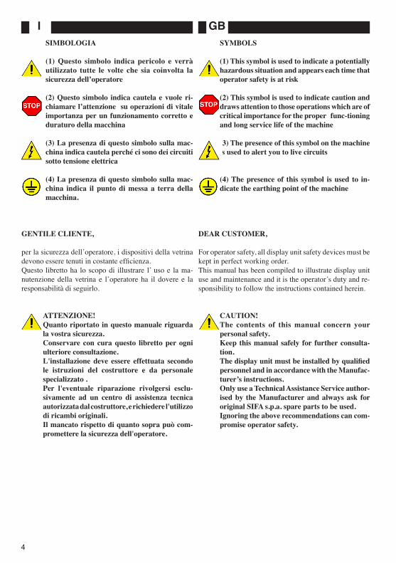
(1) This symbol is used to indicate a potentially hazardous situation and appears each time that operator safety is at risk
(2) This symbol is used to indicate caution and draws attention to those operations which are of critical importance for the proper func-tioning and long service life of the machine
(3) The presence of this symbol on the machine is used to alert you to live circuits
(4) The presence of this symbol is used to in-dicate the earthing point of the machine
DEAR CUSTOMER,
For operator safety, all display unit safety devices must be kept in perfect working order.This manual has been compiled to illustrate display unit use and maintenance and it is the operatorʼs duty and re-sponsibility to follow the instructions contained herein.
CAUTION!The contents of this manual concern your personal safety.Keep this manual safely for further consulta-tion.The display unit must be installed by qualified personnel and in accordance with the Manufac-turerʼs instructions.Only use a Technical Assistance Service author-ised by the Manufacturer and always ask for original SIFA s.p.a. spare parts to be used.Ignoring the above recommendations can com-promise operator safety.
SIMBOLOGIA
(1) Questo simbolo indica pericolo e verrà utilizzato tutte le volte che sia coinvolta la sicurezza dellʼoperatore
(2) Questo simbolo indica cautela e vuole ri-chiamare lʼattenzione su operazioni di vitale importanza per un funzionamento corretto e duraturo della macchina
(3) La presenza di questo simbolo sulla mac-china indica cautela perché ci sono dei circuiti sotto tensione elettrica
(4) La presenza di questo simbolo sulla mac-china indica il punto di messa a terra della macchina.
GENTILE CLIENTE,
per la sicurezza dellʼoperatore, i dispositivi della vetrina devono essere tenuti in costante efficienza. Questo libretto ha lo scopo di illustrare l ̓uso e la ma-nutenzione della vetrina e lʼoperatore ha il dovere e la responsabilità di seguirlo.
ATTENZIONE!Quanto riportato in questo manuale riguarda la vostra sicurezza.Conservare con cura questo libretto per ogni ulteriore consultazione.L'installazione deve essere effettuata secondo le istruzioni del costruttore e da personale specializzato .Per l'eventuale riparazione rivolgersi esclu-sivamente ad un centro di assistenza tecnica autorizzata dal costruttore, e richiedere l'utilizzo di ricambi originali.Il mancato rispetto di quanto sopra può com-promettere la sicurezza dell'operatore.

FD
5
SYMBOLES
(1) Ce symbole indique un danger et il est utilisé chaque fois que la sécurité de lʼopérateur est compromise
(2) Ce symbole invite à la précaution et il attire lʼattention en ce qui concerne des opérations dʼimportance vitale pour le fonctionnement correct et durable de la machine
(3) La présence de ce symbole sur la machine invite à la précaution car il y a des circuits sous tension électrique
(4) La présence de ce symbole sur la machine in-dique le point de mise à la terre de la machine.
CHER CLIENT
pour la sécurité de lʼopérateur, les dispositifs de la vitri-ne doivent être maintenus constamment en conditions dʼefficacité.Ce guide a pour but dʼillustrer lʼutilisation et lʼentretien de la vitrine et lʼopérateur a le devoir et la responsabilité de le respecter.
ATTENTION!Lʼensemble des indications reportées dans ce guide concerne votre sécurité.Conserver avec soin ce guide pour toute consul-tation ultérieure.Lʼinstallation doit être effectuée selon les in-structions du constructeur et par le personnel qualifié.Pour toute réparation éventuelle, sʼadresser exclusivement à un centre dʼassistance techni-que autorisé par le constructeur, et réclamer lʼemploi des pièces détachées originales.Le non respect des instructions ci-dessus peut compromettre la sécurité de lʼopérateur.
SYMBOLIK
(1) Dieses Symbol bedeutet Gefahr und wird immer dann verwendet, wenn die Sicherheit des Bedieners gefährdet ist.
(2) Dieses Symbol bedeutet Vorsicht und lenkt die Aufmerksamkeit auf Vorgänge, die für eine korrekte und dauerhafte Funktionstüchtigkeit der Maschine von grundlegender Wichtigkeit sind.
(3) Dieses Symbol bei der Maschine bedeutet Vorsicht, da die Stromkreise unter Spannung stehen.
(4) Dieses Symbol bei der Maschine zeigt den Erdung-spunkt der Maschine an.
SEHR GEEHRTER KUNDE,
zum Schutz des Bedieners müssen die Vitrinenvorrichtungen laufend instandgehalten werden. Dieses Handbuch soll die Bedienung und Wartung der Vitrine erläutern, und der Bediener hat die Pflicht und Verantwortung, die darin enthaltenen Anweisungen zu befolgen.
ACHTUNG!Der Inhalt dieses Handbuches betrifft Ihre Sicher-heit.Dieses Handbuch muß für eventuelle Informationen sorgfältig aufbewahrt werden.Die Installation muß, gemäß den Anweisungen des Herstellers, von Fachpersonal durchgeführt werden.Eventuelle Reparaturen sollen unter Verwendung von Originalersatzteilen und ausschließlich von technischen Kundendienstzentren, die vom Hersteller autorisiert sind, durchgeführt werden.Die Nichtbeachtung der zuvor genannten Punkte kann die Sicherheit des Bedieners gefährden.
I GB
6
CONDIZIONI GENERALI DI VENDITA E GARANZIA
1) La Ditta SIFA s.p.a. garantisce il proprio prodotto, in condizioni di uso normale come da norme e dati tecnici specificati nella documentazione illustrativa (non vi sono garanzie per un uso diverso da quello descritto nella documentazione SIFA s.p.a.) per un periodo di 12 mesi dalla consegna o ritiro della merce, a condizione che l'apposito tagliando timbrato e dato dal Concessonario, venga rispedito a SIFA s.p.a. entro dieci giorni dalla consegna della stessa.La garanzia termina 12 mesi dopo l'effettuazione della fornitura, indipendentemente, dal fatto che i prodotti siano stati o meno venduti.
2) Il Certificato di Garanzia dovrà essere conservato dall'utilizzatore ed esibito ogni qualvolta si richieda un intervento in garanzia. Il suo smarrimento o alterazione tale da procurarne l'illeggibilità comporta l'immediato decadimento della stessa.
3) La garanzia comprende: la sostituzione gratuita del motocompressore o, in generale, di quelle parti dello stesso motocompressore che ad insindacabile giudizio della SIFA s.p.a., risultino difettose esclusivamente per vizi di fabbricazione o materiale.Fatta eccezione per quanto espressamente previsto nel Certificato di garanzia si esclude ogni ulteriore forma di garanzia espressa o tacita. Inoltre sono esclusi da garanzia i danni conseguenti a trascuratezza , cattivo uso o improprio, insufficiente o non ordinaria manu-tenzione, manomissione da parte del compratore o di terzi, imperizia ed installazione non corrispondente alle norme tecniche fornite dalla SIFA s.p.a., o altre cause non imputabili alla venditrice stessa.Nessun ampliamento della garanzia è dovuto alla SIFA s.p.a. salvo casi sopra descritti.
4) L'eventuale sostituzione della parte difettosa non comporta l'estensione o il rinnovo delle condizioni di garanzia. Le parti difettose e/o sostituite devono essere obbligatoriamente restituite alla SIFA s.p.a. in porto franco.L'installazione e l'assistenza in garanzia sono compe-tenza del Concessonario presso il quale il prodotto è stato acquistato.
5) Per eventuale controversia è fatta espressa deroga a favore esclusivamente del Foro di Pesaro, con tacita accettazione finora da parte dell'acquirente.
.
GENERAL CONDITIONS OF SALEAND GUARANTEE
1) The Company SIFA s.p.a. guarantees this product in conditions of normal use, as required by the standards and technical specifications contained in the illustrated documents (the Guarantee does not cover any use other than that described in the SIFA s.p.a. documents), for a period of 12 months from the date of delivery or collection of goods. This Guarantee is subject to the sending of the attached counterfoil, stamped and dated by the Authorised Dealer, to SIFA s.p.a. within ten days of delivery.
This guarantee expires 12 months from the date of delivery, independently of whether or not the machine has been sold on.
2) The Guarantee Certificate must be retained by the User and shown each time that servicing is requested under guarantee. The loss of this Certificate or any modifica-tion thereof, such as may bring about its illegibility, will render the Guarantee null and void.
3) The Guarantee covers: the replacement, free of charge and at the sole option of SIFA s.p.a., of the motor-driven compressor or, in general, of those parts which due to defects in material or workmanship are judged to be defective.
Excepting that specified in this Guarantee Certificate, no other form of guarantee, either express or implied, is given with respect to this product. Furthermore, damage due to neglect, incorrect or misuse of the product, main-tenance or service not in accordance with this manual, modifications carried out by the purchaser or third par-ties, inexperience and installation not in accordance with the technical standards supplied by SIFA s.p.a., is not covered by the Guarantee, nor is any other cause which cannot be attributed directly to the Vendor.
No extensions of Guarantee coverage will be granted by SIFA s.p.a., excepting in those cases described above.
4) Any replacement of defective parts does not imply the extension or renewal of these Guarantee conditions. All defective and/or replaced parts shall be returned, carriage paid, to SIFA s.p.a. Installation and assist-ance under guarantee are the sole responsibility of the Authorised Dealer from whom the product was purchased.
5) Any dispute arising from the present General Condi-tions of Sale and Guarantee shall fall within the sole competence of the Court of Pesaro, Italy, with the tacit acceptance of the Purchaser.
FD
7
ALLGEMEINE VERKAUFS- UND GARANTIEBEDINGUNGEN
1) Die Firma SIFA s.p.a. garantiert das Produkt für einen Zeitraum von 12 Monaten ab Lieferung oder Abholung der Ware unter der Bedingung, daß es vorschriftsmäßig, laut den in der erklärenden Dokumentation angegebenen Normen und technischen Angaben, verwendet wird (es besteht keinerlei Garantieanspruch, wenn das Produkt nicht entsprechend den Angaben der Dokumentation der Firma SIFA s.p.a. verwendet wird), und unter der Bedingung, daß die mit Stempel und Da-tum des Händlers versehene Garantiekarte innerhalb von zehn Tagen nach Lieferung an SIFA s.p.a. rückgesandt wird.
Die Garantie endet 12 Monate nach der Lieferung unabhängig davon, ob die Produkte verkauft wurden oder nicht.
2) Der Garantieschein ist vom Abnehmer aufzubewahren und jeweils bei Inanspruchnahme der Garantie vorzuzeigen. Bei Verlegen bzw. Unleserlichkeit aufgrund von Veränderungen verfällt jeglicher Garantieanspruch.
3) Unter die Garantieleistungen fallen: kostenloser Austausch des Kompressors oder im allgemeinen der Kompressorteile, die nach dem unanfechtbaren Urteil der Firma SIFA s.p.a. ausschließlich aufgrund von Fabrikations- oder Materials-chäden defekt sind.
Es gelten ausschließlich die im Garantieschein aufgeführten Bestimmungen, jegliches anderweitige mündliche bzw. stills-chweigende Übereinkommen wird abgelehnt. Nicht unter die Garantieleistungen fallen Schäden, die durch Nachlässigkeit, unsachgemäßen oder unpassenden Gebrauch, unzureichende oder außerordentliche Wartung, falsche Handhabung durch den Käufer oder Dritte, Unerfahrenheit, Installation nicht gemäß den von der Firma SIFA s.p.a. gelieferten Fachnor-men, oder aus anderen Gründen, die nicht dem Verkäufer zugeschrieben werden können, entstanden sind.
SIFA s.p.a. ist ausschließlich in oben genannten Fällen zu Garantieleistungen verpflichtet.
4) Bei Austausch des defekten Teiles besteht keine Verlängerung oder Erneuerung der Garantie. Alle schadhaften und/oder ausgetauschten Teile sind verbindlich der Firma SIFA s.p.a. spesenfrei zurückzuerstatten.
Installation und Kundendienst in der Garantiezeit unterliegen der Zuständigkeit des Vertragshändlers, bei dem das Produkt gekauft wurde.
5) Bei eventuellen Streitfragen ist ausschließlich das Gericht von Pesaro zuständig und wird schon jetzt vom Käufer stillsch-weigend angenommen.
CONDITIONS GENERALES DE VENTE ET DE GARANTIE
1) L̓ Entreprise SIFA s.p.a. garantit le produit, aux condi-tions dʼutilisation normale selon les normes et données techniques spécifiées dans la documentation explicative (il nʼy a pas de garantie pour un usage différent de celui décrit dans la documentation SIFA s.p.a.) sur une période de 12 mois à dater de la livraison ou du retrait de la marchandise, à condition que le coupon portant le cachet du Concessionnaire et la date dʼachat soit retourné à Sifa s.p.a. dans les dix jours successifs à la date de livraison de cette marchandise.
La garantie échoit 12 mois après la livraison de la mar-chandise, indépendamment du fait que les produits aient été ou non vendus.
2) Le Certificat de Garantie devra être conservé par lʼuti-lisateur et présenté chaque fois quʼune intervention sous garantie sera nécessaire. La perte ou altération de ce Certificat entraînant son illisibilité comporte la déchéance immédiate de la Garantie.
3) La garantie comprend: le remplacement gratuit du motocompresseur ou, en général, des composants du motocompresseur qui résultent, selon le jugement sans appel de SIFA s.p.a., défectueux exclusivement pour vices de fabrication ou de matériel.
Exception faite de ce qui est expressément prévu dans le Certificat de Garantie, toute autre forme de garantie tacite ou exprimée est exclue. En outre, la garantie ne couvre pas: les dommages dérivant dʼune négligence, dʼun usage impropre ou abusif, dʼun entretien insuffisant ou non périodique, dʼune altération de la part de lʼache-teur ou de tiers, de lʼinexpérience, dʼune installation non correspondante aux normes techniques fournies par SIFA s.p.a., ou toute autre cause non imputable au vendeur lui-même.
Aucune étendue de la garantie nʼest due par SIFA s.p.a., sauf pour les cas sus-mentionnés
4) Le remplacement éventuel de la partie défectueuse ne comporte ni lʼextension ni le renouvellement des conditions de garantie. Les parties défectueuses et/ou remplacées doivent être obligatoirement retournées à SIFA s.p.a. franco de port.
Lʼinstallation et le service après-vente sous garantie sont de compétence du Concessionnaire auprès duquel le produit a été acheté.
5) Dans le cas dʼune éventuelle controverse, une déro-gation expresse est fai te en faveur exclusive du Tribunal de Pesaro, par acceptation tacite de la part de lʼacheteur.
I GB
8
Sommario
1 SPECIFICHE TECNICHE .........................................................101.1 DESCRIZIONE DELLA VETRINA .....................................101.2 NORME APPLICATE ............................................................121.3 POSTAZIONE DI LAVORO ..................................................14 1.4 ACCESSORI ..........................................................................141.5 MODELLI ..............................................................................141.6 IDENTIFICAZIONE ...............................................................161.7 DIMENSIONI DI INGOMBRO E PESI ................................161.8 CARATTERISTICHE TECNICHE .......................................16
2 INSTALLAZIONE .....................................................................182.1 TRASPORTO .........................................................................182.2 SOLLEVAMENTO E MOVIMENTAZIONE ........................182.3 SPECIFICHE AMBIENTALI .................................................202.4 POSIZIONAMENTO ..............................................................202.4.1. CANALIZZAZIONE VETRINA REFRIGERATA CON
VETRINA REFRIGERATA O VETRINA NEUTRA CON VETRINA NEUTRA ............................................................22
2.4.2. CANALIZZAZIONE VETRINA REFRIGERATA CON VETRINA NEUTRA ...........................................................22
2.5 SPAZI MANUTENTIVI .........................................................242.6 COLLEGAMENTO UNITA' REMOTA DI REFRIGERAZIO-
NE .........................................................................................242.7 COLLEGAMENTO ELETTRICO ..........................................262.8 NOTE AMBIENTALI .............................................................26
3 ESERCIZIO ...................................................................................283.1 AVVIAMENTO E REGOLAZIONE DELLA TEMPERATURA
283.2 FERMATA DELLA MACCHINA ...........................................32
4 MANUTENZIONE ORDINARIA ................................................344.1 OPERAZIONI PRELIMINARI DI SICUREZZA .................344.2 PULIZIA CONDENSATORE ................................................344.3 PULIZIA VETRINA ..............................................................36
- PULIZIA ESTERNO VETRINA ...........................................36- PULIZIA PIANO DI ESPOSIZIONE REFRIGERATO .......36
4.4 SBRINAMENTI ......................................................................38- SBRINAMENTO AUTOMATICO .......................................38- SBRINAMENTO MANUALE ..............................................38- SBRINAMENTO CON FERMO MACCHINA ....................38
5 MANUTENZIONE STRAORDINARIA .....................................405.1 OPERAZIONI PRELIMINARI DI SICUREZZA ..................405.2 SOSTITUZIONE DELLE SUPERFICI VETRATE ...............405.3 SOSTITUZIONE LAMPADE - REATTORI - STARTER ......425.4 SOSTITUZIONE RESISTENZA ANTICONDENSA ............44
6 ANOMALIE DI FUNZIONAMENTO ......................................46
7 CATALOGO RICAMBI ..............................................................54
Contents
1 TECHNICAL SPECIFICATIONS ............................................. 10 1.1 DESCRIPTION OF THE DISPLAY UNIT ..........................10 1.2 STANDARDS AND REGULATIONS .................................12 1.3 OPERATOR AREA ...............................................................14 1.4 ACCESSORIES .....................................................................14 1.5 UNIT RANGES .....................................................................14 1.6 PRODUCT IDENTIFICATION ............................................16 1.7 WEIGHTS AND OVERALL DIMENSIONS .......................16 1.8 TECHNICAL DETAILS .......................................................16
2 INSTALLATION ....................................................................... 18 2.1 TRANSPORT ........................................................................18 2.2 LIFTING AND HANDLING ................................................18 2.3 AMBIENT CONDITIONS ....................................................20 2.4 POSITIONING ......................................................................20 2.4.1. HOW TO CONNECT TWO REFRIGERATED DISPLAY
UNITS OR TWO NON-REFRIGER. DISPLAY UNITS ..22 2.4.2. HOW TO CONNECT A REFRIGERATED
DISPLAY UNIT TO A NON-REFRIGERATED DISPLAY UNIT .....................................................................................22
2.5 MAINTENANCE AREAS .....................................................242.6 HOW TO CONNECT A DETACHED REFRIGERATING
UNIT .....................................................................................242.7 ELECTRICAL CONNECTIONS ...........................................262.8 ENVIRONMENTAL MEASURES ........................................26
3 OPERATION ................................................................................ 283.1 START UP AND TEMPERATURE
REGULATION .....................................................................283.2 HOW TO SWITCH OFF THE MACHINE ............................32
4 ROUTINE MAINTENANCE ......................................................344.1 PRELIMINARY SAFETY CHECKS ....................................344.2 CLEANING THE CONDENSER ...........................................344.3 CLEANING THE DISPLAY UNIT ........................................36- CLEANING THE DISPLAY UNIT EXTERIOR .......................36- CLEANING THE REFRIGERATED
DISPLAY TOP .....................................................................364.4 DEFROSTING .......................................................................38- AUTOMATIC DEFROST ...........................................................38- MANUALLY OPERATED DEFROST ......................................38- DEFROSTING WHEN THE MACHINE IS OFF .....................38
5 SPECIAL MAINTENANCE .............................................405.1 PRELIMINARY SAFETY CHECKS ....................................405.2 REPLACING THE GLASS SURFACES ..............................405.3 REPLACING-LAMP - REACTOR - STARTER ..................425.4 REPLACING THE ANTI-CONDENSATE
RESISTOR ..........................................................................44
6 TROUBLESHOOTING ....................................................46
7 REPLACEMENT PARTS CATALOGUE .......................54

FD
9
Inhaltsverzeichnis
1 TECHNISCHE ANGABEN ......................................................... 111.1 BESCHREIBUNG DER VITRINE ....................................... 111.2 GÜLTIGE NORMEN ............................................................131.3 ARBEITSPLATZ .....................................................................151.4 ZUBEHÖR ............................................................................151.5 MODELLE ................ .............................................................151.6 IDENTIFIZIERUNG ...............................................................171.7 AUSMASSE UND GEWICHTE ...........................................171.8 TECHNISCHE MERKMALE ..........................................17
2 INSTALLATION .......................................................................192.1 TRANSPORT .........................................................................192.2 HEBEN UND VERSTELLEN ........................................192.3 UMWELTBEDINGUNGEN ...................................................212.4 POSITIONIEREN ...................................................................212.4.1. ZUSAMMENBAU VON ZWEI VITRINEN MIT KÜHLAG-
GREGAT ODERVON ZWEI VITRINENOHNE ....................KÜHLAGGREGAT ..............................................................23
2.4.2. ZUSAMMENBAU EINER VITRINE MIT KÜHLAGGRE-GAT UND EINER VITRINE OHNE KÜHLAGGREGA ...23
2.5 FREIZUHALTENDE ZONEN FÜR WARTUNG ..................252.6 ANSCHLUSS DISTANZIERTE KÜHLEINHEIT .................252.7 ELEKTRISCHER ANSCHLUSS ...........................................272.8 HINWEISE ZUM SCHUTZ DER UMWELT ........................27
3 BETRIEB ....................................................................................... 293.1 ANLAUF UND TEMPERATURREGELUNG ......................293.2 STILLSETZEN DER MASCHINE .......................................33
4 WARTUNG .....................................................................................354.1 EINLEITENDE SCHUTZMASSNAHMEN .........................354.2 KONDENSATORREINIGUNG ............................................354.3 REINIGUNG VITRINE .........................................................37- AUSSENREINIGUNG VITRINE ..............................................37- REINIGUNG GEKÜHLTE AUSSTELLUNGSFLÄCHE .........374.4 ABTAUEN ...............................................................................39- AUTOMATISCHES ABTAUEN ................................................39- MANUELLES ABTAUEN .........................................................39- ABTAUEN BEI STILLSTEHENDER MASCHINE ..................39
5 AUSSERORDENTLICHE WARTUNG .....................................415.1 EINLEITENDE SCHUTZMASSNAHMEN ..........................415.2 AUSTAUSCH VON GLASFLÄCHEN ..................................415.3 AUSTAUSCH LAMPEN- DROSSELSPULEN- STARTER 435.4 AUSTAUSCH ANTIKONDENSATWIDERSTAND .............45
6 BETRIEBSSTÖRUNGEN ..........................................................47
7 ERSATZTEILKATALOG ......................................................... 55
Sommaire
1 SPECIFICATIONS TECHNIQUES ............................................ 111.1 DESCRIPTION DE LA VITRINE ........................................ 111.2 NORMES APPLIQUEES .......................................................131.3 POSITION DE TRAVAIL .......................................................151.4 ACCESSOIRES .......................................................................151.5 MODELES ..............................................................................151.6 IDENTIFICATION ..................................................................171.7 DIMENSIONS DʼENCOMBREMENT ET POIDS ..............171.8 CARACTERISTIQUES TECHNIQUES ...............................17
2 INSTALLATION ..........................................................................192.1 TRANSPORT .........................................................................192.2 SOULEVEMENT ET DEPLACEMENT ................................192.3 SPECIFICATIONS AMBIANTES ..........................................212.4 POSITIONNEMENT ..............................................................212.4.1. ASSEMBLAGE VITRINE REFRIGEREE AVEC VITRINE REFRIGEREE OU VITRINE NON REFRIGEREE
AVEC VITRINE NON REFRIGEREE ................................232.4.2. ASSEMBLAGE VITRINE REFRIGEREE AVEC VITRINE
NON REFRIGEREE ............................................................232.5 ESPACES DʼENTRETIEN .....................................................252.6 BRANCHEMENT UNITE DE REFRIGERATION PLACEE A DISTANCE .............................................................252.7 BRANCHEMENT ELECTRIQUE .........................................272.8 REMARQUES SUR LʼENVIRONNEMENT .........................27
3 FONCTIONNEMENT ..................................................................293.1 DEMARRAGE ET REGULATION DE LA TEMPERATURE .....................................................................293.2 ARRET DE LA MACHINE ....................................................33
4 ENTRETIEN ORDINAIRE ..........................................................354.1 OPERATIONS PRELIMINAIRES DE SECURITE ..............354.2 NETTOYAGE DU CONDENSEUR ......................................354.3 NETTOYAGE DE LA VITRINE ...........................................37- NETTOYAGE EXTERNE DE LA VITRINE ............................37- NETTOYAGE DU PLAN DʼEXPOSITION REFRIGERE ..............................................................................374.4 DEGIVRAGES ........................................................................39- DEGIVRAGE AUTOMATIQUE ...............................................39- DEGIVRAGE MANUEL ...........................................................39- DEGIVRAGE AVEC ARRET MACHINE .................................39
5 ENTRETIEN EXTRAORDINAIRE ............................................415.1 OPERATIONS PRELIMINAIRES DE SECURITE ...............415.2 REMPLACEMENT DES SURFACES VITREES ..................415.3 REMPLACEMENT LAMPE - REACTEUR - STARTER ...............................................................................435.4 REMPLACEMENT RESISTANCE ANTI-CONDENSATION .......... 45
6 ANOMALIES DE FONCTIONNEMENT ................................47
7 CATALOGUE DES PIECES DETACHEES .............................55

I GB
10
1 SPECIFICHE TECNICHE
1.1 DESCRIZIONE DELLA VETRINA
CON CASSETTI ESTRAIBILI Moduli con cassetti in acciaio inox scorrevoli su guide. Struttura inferiore ad elementi metallici, rivestimenti superiori in acciaio inox e vetri temperati curvi apribili verso lʼalto. Due mensole intermedie fisse in vetro con plafoniere di illuminazione complete di schermo protettivo in metacri-lato; mensola inferiore in vetro, più profonda, refrigerata. Montanti e plafoniere in alluminio anodizato a trattamento ecologico. Piano di servizio posteriore in acciaio inox. Resistenze anticondensa dei vetri nel profilo anteriore. Scorrevoli retrosuperiori in plexiglas, refrigerazione statica con gas R404A, unità condensatrice incorporata e scorrevole posteriormente su guide. Centralina elettronica di controllo con sbrinamento programmabile a 2/4 cicli giornalieri. Coibentazione con schiume poliuretaniche prive di CFC.
A PIANO FISSO Le caratteristiche costruttive generali sono le stesse del modello precedente, ad eccezione del piano che è fisso, in-clinato e refrigerato, con plateaux in acciaio inox estraibili; ed è privo della mensola inferiore in vetro, più profonda e refrigerata. La gamma è completata da un modulo angolare refrigerato e non refrigerato.
N°1
Miss
1 WITH EXTRACTABLE DRAWERS
1.1 DESCRIPTION OF THE DISPLAY UNIT
WITH EXTRACTABLE DRAWERSUnits with stainless steel drawers which pull out on run-ners. Metal base framework, upper unit coating in stainless steel and curved, lift-up front in toughened glass. Two fixed, dividing shelves in glass with downlights fitted with protective methacrylate shields; larger, refrigerated bottom glass shelf. Risers and downlight frames in aluminium, anodised using an environmentally friendly process. Rear work top in stainless steel. Anti-mist resistance for the glass, fitted inside the front profile. Rear sliding doors in Plexiglas. Static refrigeration with R404A gas, built-in condenser, which pulls out on runners and is sited at the rear of the unit. Electronic control panel with program-mable defrost function: 2/4 cycles daily. Insulation with CFC free polyurethane foarn.
WITH FIXED TOPThe general construction details are the same as those for the previous unit, except that it has a display top which is fixed, inclined and refrigerated. The unit also has remov-able, stainless steel trays but is not fitted with the larger. refrigerated bottom shelf in glass. The line is completed by refrigerated and non-refngerated corner units.

FD
11
N°2
1 TECHNISCHE ANGABEN
1.1 BESCHREIBUNG DER VITRINE
MIT AUSZIEHBAREN SCHUBLADEN Komponenten mit Edelstahl Schubladen auf Schienen. Untere Struktur aus Metallelementen, Oberverkleidung Inox Stahl und Panoramascheiben, aus gehartetem, gekri-immten Glas, offnen sich nach oben. Zwei feste Zwischen-ablagen aus Glas mit Deckenleuchten und Blendschutz aus Metacrylat; untere breite Glaskonsole, mit Kuhlung. Stander und Deckenleuchten aus eloxiertem Aluminium, umweltfreundlich behandelt. Hintere Bedienungsflache aus Edelstahl. Elektrische Wlderstande am vorderen Pro-fil der Scheiben zur Verhinderung von Kondensbildung. Schiebturen auf Plexiglas auf der Ruckseite, statische R404A t,askuhlung, eingebaute Kondensatoreinheit hinten auf Schienen. Elektronisches Regelsystem mit program-mierbarer Abtauung mit 2/4 Zyklen taglich. Isolierung mit PUR-Schaum ohne CFC.
MIT FESTER KONSOLEDie allgemeinen Baumerkmale sind dieselben des vo!merigen Modells, mit Ausnahme der Konsole, die fest, geneigt und gekühlt ist; herausnehmbare plateaux aus Edelstahl; ohne Glasablage. Das Sortiment wird mit gekühten und ungekühlten Eckmodulen ergänzt.
1 SPECIFICATIONS TECHNIQUES
1.1 DESCRIPIION DE LA VITRINE
AVEC TIROIRS AMOVIBLESModules avcc tiroirs en acier inox coulissants sur glis-sières. Structure inférieure à éléments métalliques, revéte-ments supérieurs en aciel inox et vitres en verre trempé bombées et relevables. Deux étagères interrnédiaires fixes en verre avec plafonniers dʼéclaurage équipés dʼun écran de protection en métbacrylate; étagère inférieure en verre, plus profonde, réfrigérée. Montants et plafonniers en alu-minium anodisé par traitement écologique. Plan arrière de service en acier inox. Résistances pour le dégivrage des vitres incorporées dans le profil antérieur. Vltres arrières supérieures coulissantes en Plexiglas. Froid statique avec gaz R404A, unité de condensation incorporée à lʼarrière et coulissante sur glissières. Panneau de controle électronique avec dégivrage programmable à 2/4 cycles quotidiens. Isolation par mousses de polyurethane sans les CFC.
AVEC PLAN FIXELes caractéristiques générales de construction sont les me-mes que celles du modèle précédent, en dehors du plan qui est fixe, incliné et réfrigéré, avec des plateaux en acier inox amovibles; ce modèle manque de lʼétagère inférieure en verre, plus profonde et réfrigérée. La gamme est complétée par un module angulaire réfrigéré et non réfrigéré.
I GB
12
1.2 NORME APPLICATE
La vetrina é conforme alla direttiva sulla compatibilità ele-tromagnetica 89/336-93/68 CEE e risponde alle norme:
EN 61000-3-2Parte 3:Limiti Sezione 2:Limite per le emissioni di corrente armonica (apparecchiature con corrente di ingresso 16 A per fase).
EN 61000-3-3Parte 3:Limiti Sezione 3:Limiti delle fluttuazioni di tensione del flicker in sistemi di alimentazione in bassa tensione per apparec-chiature con corrente nominale 16 A.
EN 55014-1Limiti e metodi di misura delle caratteristiche di radio-disturbo degli apparecchi elettrodomestici e similari o termici, degli utensili elettrici e degli apparecchi elettrici similari.
EN 55014-2Requisiti di immunità per gli elettrodomestici, utensili e degli apparecchi elettrici similariInoltre la vetrina è conforme alla direttiva sulla sicurezza elettrica 73/23-93/68 CEE e risponde alle norme:
EN 60335-1Parte 1: Norme generaliSicurezza degli apparecch elettrici ad uso domestico e similare.
EN 60335-2-24Parte II: Norme particolari per frigoriferi e congelatori.Uso degli apparecchi dʼuso domestico e similare.
1.2 STANDARDS AND REGULATIONS
The refrigerated display unit complies with the electro-magnetic compatibility standards 89/336-93/68 ECC and with the following standards:
EN 61000-3-2Part 3: Limits Section 2: Limits for harmonic current emissions (equip-ment input current 16 A per phase)
EN 61000-3-3Part 3: Limits Section 3: Limitation of voltage fluctuations and flicker in low-voltage supply systems for equipment with rated current 16 A.
EN 55014-1Limits and methods of measurement of radio disturbance characteristics of electrical motor-operated and thermal appliances for household and similar purposes, electric tools and similar electric apparatus.
EN 55014-2Immunity requirements for household appliances, tools and similar apparatusesThe glass case is also in compliance with the directive on electrical safety 73/23-93/68 CEE and Product family standard
EN 60335-1Safety of household and similar electrical appliances.
EN 60335-2-24Part II: Particular norms for refrigerators and freezers.Use of household appliances and similar.

FD
13
1.2 GÜLTIGE NORMEN
Die Vitrine entspricht den Richtlinien überdie Elektro-magnetische Kompatibilität 89/336-93/68 CEE und ist normenmässig:
EN 61000-3-2Teil 3: GrenzwerteHauptabschnitt 2:Grenzwerte für Oberschwingungsströme (Geräte-Eingangsstrom 16 A je Leiter)
EN 61000-3-3Teil 3: GrenzwerteHauptabschnitt 3: Grenzwerte für Spannungsschwankun-gen und Flicker in Niederspannungsnetzen für Geräte mit einem Eingangsstrom 16 A.
EN 55014-1Grenzwerte und Messverfahren für Funkstörungen von Geräten mit elektromotorischem Antrieb und Ele-ktrowärmegeräten für den Hausgebrauch und ähnliche Zwecke, Elektrowerkzeugen und ähnlichen Elektrog-eräten
EN 55014-2Störfestigkeitsanforderungen für Haushaltsgeräte, Werkzeuge und ähnliche GeräteProduktfamilien-Norm
EN 60335-1Sicherheit elektrischer Geräte für den Hausgebrauch und ähnliche Zwecke Teil 1: Allgemeine Anforderungen.
EN 60335-2-24Sicherheit elektrischer Geräte für den Hausgebrauch und ähnliche ZweckeTeil 2: besondere Anforderungen für Kühlschränke und Gefriergeräte.
1.2 NORMES APPLIQUEES
La vitrine est conforme à la directive sur la compatibilité électromagnétique 89/336-93/68 CEE et répond aux normes:
EN 61000-3-2Partie 3: Limites Section 2: Limites pour les émissions de courant harmoni-que (courant appelé pour les appareils 16 A par phase).
EN 61000-3-3Partie 3: Limites Section 3: Limites des fluctuations de tension et du flicker dans les réseaux basse tension pour les équipements ayant un courant appelé 16 A.
EN 55014-1Limites et méthodes de mesure des perturbations radioé-lectriques produites par les appareils électrodomestiques ou analogues comportant des moteurs ou des dispositifs thermiques, par les outils électriques et par les appareils électriques analogues.
EN 55014-2Exigences dʼimmunité pour les appareils électrodomesti-ques, outils électriques et appareils analoguesNorme de famille de produits
EN 60335-1Sécurité des appareils électrodomestiques et analoguesPremière partie: Règles générales.
EN 60335-2-24Sécurité des appareils électrodomestiques et analoguesDeuxième partie: Règles particulières pour les réfrigérateurs et congélateurs.

I GB
14
1.3 OPERATOR AREA
The display unit operator area is situated behind the unit itself and contains the start and temperature adjustment controls. In this area there is also an opening for access to the display top and refrigerating cell.
1.4 ACCESSORIES
Machine accessories are as follows (Fig.N° 3):- Fully-incorporated refrigerating unit with water con-densation unit;- Detached refrigerating unit (Pos.1);- Refrigerating unit for two downlights (without refrigerat-ing unit) (Pos.2);- Refrigerating unit for 2 downlights (sufficient for max.3m of counter) (Pos.3);- Fixed partition (Pos.4); - Hot shelf (Pos.5).
l.5 UNIT RANGES
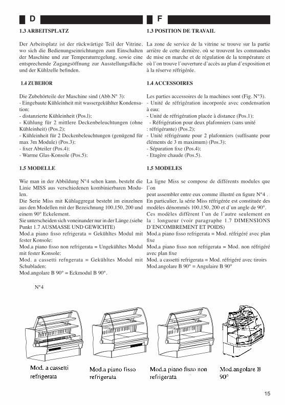
The MISS range includes different modular units that can be connected together, as shown in Fig. N° 4.In particular, the models in the range of Miss refrigerated units are classified as follows: 100,150, 200, and 90° corner unit.These units differ in terms of length only (see Section 1.7 WEIGHTS AND OVERALL DIMENSIONS).Mod.a piano fisso refrigerata = Refrigerated unit with fixed, display top;Mod.a piano fisso non refrigerata = Non-refrigerated unit with fixed display top; Mod. a cassetti refrigerata = Refrigerated unit with drawers;Mod.angolare B 90° = B 90° corner unit.
N°3
1.3 POSTAZIONE DI LAVORO
La zona di lavoro per la vetrina è posta nella parte poste-riore di questa, dove vi sono i comandi di accensione e di regolazione della temperatura e cʼè lʼapposita apertura per accedere al piano di esposizione ed alla celle di riserva.
1.4 ACCESSORI
Le parti accessorie della macchina sono (Fig.N°3): - Unità refrigerante incorporata con condensazione ad
acqua.- Unità refrigerante remota (pos. 1).- Refrigerazione per due plafoniere (senza unità refrig-
erante) (Pos.2). - Unità refrigerante per 2 plafoniere (sufficiente per
max.3m di moduli) (Pos.3). - Divisorio fisso (Pos.4).- Mensola calda (Pos.5).
1.5 MODELLI
La linea MISS si compone di vari moduli canalizzabili come si vede in figura N°4 . La serie Miss refrigerata in particolare è costituita dai modelli denominati 100,150, 200 e un angolare di 90°. Questi differiscono tra loro solo per la lunghezza (vedi para. 1.7 DIMENSIONI Dl INGOMBRO E PESI).Mod. a piano fisso refirgerata.Mod. a piano fisso non refrigerata.Mod. a cassetti refrigerataMod. angolare B 90°=90°.
5
4
2
FD
15
1.3 ARBEITSPLATZ
Der Arbeitsplatz ist der rückwärtige Teil der Vitrine, wo sich die Bedienungseinrichtungen zum Einschalten der Maschine und zur Temperaturregelung, sowie eine entsprechende Zugangsöffnung zur Ausstellungsfläche und der Kühlzelle befinden.
1.4 ZUBEHOR
Die Zubehörteile der Maschine sind (Abb.N° 3):- Eingebaute Kühleinheit mit wassergekühlter Kondensa-tion;- distanzierte Kühleinheit (Pos.l);- Kühlung für 2 mittlere Deckenbeleuchtungen (ohne Kühleinheit) (Pos.2);- Kühleinheit für 2 Deckenbeleuchtungen (genügend für max 3m Module) (Pos.3);- fixer Abteiler (Pos.4);- Warme Glas-Konsole (Pos.5);
1.5 MODELLE
Wie man in der Abbildung N°4 sehen kann, besteht die Linie MISS aus verschiedenen kombinierbaren Modu-len.Die Serie Miss mit Kühlaggregat besteht im einzelnen aus den Modellen mit der Bezeichnung 100,150, 200 und einem 90° Eckelement.Sie unterscheiden sich voneinander nur in der Länge.(siehe Punkt 1.7 AUSMASSE UND GEWICHTE)Mod.a piano fisso refrigerata = Gekühltes Modul mit fester Konsole;Mod.a piano fisso non refrigerata = Ungekühltes Modul mit fester Konsole;Mod. a cassetti refngerata = Gekühltes Modul mit Schubladen;Mod.angolare B 90° = Eckmodul B 90°.
1.3 POSITION DE TRAVAIL
La zone de service de la vitrine se trouve sur la partie arrière de cette dernière, où se trouvent les commandes de mise en marche et de régulation de la température et où lʼon trouve lʼouverture dʼaccès au plan dʼexposition et à la réserve réfrigérée. 1.4 ACCESSOIRES
Les parties accessoires de la machines sont (Fig. N°3).- Unité de réfrigération incorporée avec condensation à eau;- Unité de réfrigération placée à distance (Pos.1); - Réfrigération pour deux plafonniers (sans unité: réfrigérante) (Pos.2);- Unité réfrigérante pour 2 plafonniers (suffisante pour éléments de 3 m maximum) (Pos.3);- Séparation fixe (Pos.4);- Etagère chaude (Pos.5).
1.5 MODELES
La ligne Miss se compose de différents modules que lʼonpeut assembler entre eux comme illustré en figure N°4 .En particulier, la série Miss réfrigérée est constituée des modèles dénommés 100,150, 200 et dʼun angle de 90°.Ces modèles diffèrent lʼun de lʼautre seulement en la : longueur (voir paragraphe 1.7 DIMENSIONS DʼENCOMBREMENT ET POIDS)Mod.a piano fisso refrigerata = Mod. réfrigéré avec plan fixeMod.a piano fisso non refrigerata = Mod. non réfrigéré avec plan fixeMod. a cassetti refrigerata = Mod. réfrigéré avec tiroirsMod.angolare B 90° = Angulaire B 90°
N°4

I GB
16
1.6 IDENTlFICAZlONE
Per qualsiasi comunicazione con il produttore o con i centri assistenza citare sempre il NUMERO Dl MATRICOLA della vetrina, che è apposto sulla targhetta fissata sul lata posteriore (lato operatore) della vetrina (Fig.N° 5).
1.7 DIMENSIONI Dl INGOMBRO E PESI
I valori sono riportati in tabella TN°1.
N°6N°5
fluidoXXXXXX
888±88°C espansione classe °C % umidità
KCAL/HW
V Hz W KG
XXXXXXXXXXXXXXXXXXXXXXXXXXXXXXXXXXXXXX
SIFA S.p.A.Via nazionale , 15/19 61022 COLBORDOLO (PS) -� ITALIA
®
Made in Italy
descrizione
XXXXXXXXXXXXXXXmatricola anno
KG fluido
Modello
- GRUPPO REFRIGERANTE -
XX 888888 8888
888X888 88 88888 8888
88888 88888 8,888
88
XXXXXXXXXXXXXXXXXXXXX
1.6 PRODUCT IDENTIFICATION
In all communications to the Manufacturer or to repair and services agents, please quote the display unit SERIAL NUMBER which can be found fixed to the plate on the back (operatorʼs side) of the unit (Fig.N° 5).
1.7 WEIGHTS AND OVERALL DIMENSIONS
The values are shown in Table TN°1.
1.8 CARATTERISTICHE TECNICHE 1.8 TECHNICAL DETAILS
Superficie espositiva (m2)
Display topAusstellungs-
flächePlan dʼexposition
ModuloUnitModulModule
L cm
PotenzaPower
LeistungPuissance
HP
GasGasGasGaz
100
150
200
B90°
1/5
1/3L
3/8
1/5R 404A
Resa -15°C÷+45°CFrigorieFrigorieFrigorie
Kcal/h
308
437
641
308
A B
C
FD
17
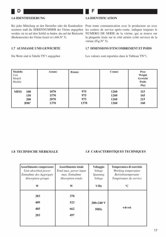
ModelloUnitModellModèle
A(mm) B(mm) C(mm) Peso WeightGewicht
Poids(Kg)
MISS 100 150 200 B90°
1070157020701370
9759759751370
1260126012601260
115165215160
1.6 IDENTIFIZIERUNG
Bei jeder Mitteilung an den Hersteller oder die Kundendien-stzentren muß die SERIENNUMMER der Vitrine angegeben werden; sie ist auf dem Schild zu finden, das auf der Rückseite (Bedienerseite) der Vitrine fixiert ist (Abb.N° 5).
1.6 IDENTIFICATION
Pour toute communication avec le producteur ou avec les centres de service après-vente, indiquer toujours le NUMERO DE SERIE de la vitrine, qui se trouve sur la plaquette fixée sur le côté arrière (côté service) de la vitrine (Fig.N° 5).
1.7 AUSMASSE UND GEWICHTE
Die Werte sind in Tabelle TN°1 angegeben
1.7 DIMENSIONS DʼENCOMBREMENT ET POIDS
Les valeurs sont reportées dans le Tableau TN°1.
1.8 CARACTERISTIQUES TECHNIQUES
Assorbimento totaleTotal max. power input
max. EntnahmeAbsorption totale
W
Assorbimento compressoreUnit absorbed power
Entnahme des AggregatsAbsorption groupe
W
VoltaggioVoltage
SpannungVoltage
V/Hz
Temperatura di esercizioWorking temperatureBetriebstemperatur
Température de service
°C
283
409
485
283
370
523
662
497
200÷240 V
50Hz +4÷+6
1.8 TECHNISCHE MERKMALE

I GB
18
N°7
2 INSTALLAZIONE
2.1 TRASPORTO
Il normale imballo è costituito da fogli di protezione di cartone ondulato o semplici fogli in nylon, a richiesta lʼazienda fornisce imballi particolari.La vetrina viene spedita normalmente su mezzi di tra-sporto via terra.
2.2 SOLLEVAMENTO E MOVIMENTAZIONE
Il carico e lo scarico della vetrina dai mezzi di trasporto va effettuata mediante trans pallet, nella seguente maniera:- Affiancate le forche di questo al livello del mezzo;- Far scorrere (secondo la lunghezza) la vetrina sopra le forche del sollevatore fino a che questa non risulti in perfetto equilibrio (N°7).
ATTENZIONE!Non spingere mai la vetrina facendo forza sulle superfici vetrate (N°8)
Una volta abbassate le forche del sollevatore scaricarla da queste nella stessa maniera.La movimentazione della vetrina a terra si effettua a mano.Lo scorrimento di questa è facilitato dalla presenza di due guide metalliche inferiori..
NOTA: se lo spostamento della vetrina deve essere fatto successivamente allo scarico si consiglia di appoggiare la vetrina su due listelli in legno in modo da favorire l'inserimento delle forche del sollevatore
2 INSTALLATION
2.1 TRANSPORT
Standard packaging comprises protective sheets of cor-rugated cardboard or plain nylon sheet. The Company will provide special packaging on request. The display unit is normally dispatched over land.
2.2 LIFTING AND HANDLING
The display unit must be unloaded from its means of trans-port using a forklift truck and following this procedure:
- Bring the truck forks level with the transporting ve-hicle;- Slide the unit (depending on its length) onto the forks of the truck and manoeuvre until the unit is perfectly balanced (N°7).
CAUTION!Never use the glass surfaces as leverage when pushing the display unit (N° 8)
When the forks have been lowered, unload the unit fol-lowing the above procedure.Once the unit is on the ground, all handling must be carried out manually. Sliding the unit has been made easier by the presence of two metal guides underneath.
NOTE: If, after unloading, the unit is to be moved at a later stage, we recommend that two strips of wood be placed underneath it in order to facilitate the insertion of the truck forks.

FD
19
NO = NONSI = OUI
NO = SI =
NO = NÃOSI = SIM
N°8
2 INSTALLATION
2.1 TRANSPORT
Die normale Verpackung besteht aus einer Schutzhülle aus Wellpappebögen oder einfacher Nylonfolie, auf Wunsch liefert die Firma auch Sonderverpackungen.Die Vitrine wird normalerweise mit Transportmitteln auf dem Landweg versandt.
2.2 HEBEN UND VERSTELLEN
Das Laden und Abladen der Vitrine auf bzw. von den Transport-mitteln muß mit Hilfe eines Handgabelhubwagens auf folgende Weise durchgeführt werden: - Die Gabeln des Handgabelhubwagens und das Transportmittel niveaugleich nebeneinander stellen, - die Vitrine (der Länge nach) solange auf die Gabeln des Handgabelhubwagens schieben, bis sie sich in perfekter Gleich-gewichtslage befindet (Nr. 7).
ACHTUNG!Beim Schieben der Vitrine darf niemals auf die Glasflächen Druck ausgeübt werden (Nr. 8)
Nachdem die Gabeln des Handgabelhubwagens wieder gesenkt wurden, wird die Vitrine auf dieselbe Weise abgeladen.Auf dem Boden wird die Vitrine mit den Händen geschoben.Das Verstellen wird durch zwei Metallschienen auf der Unterseite der Vitrine erleichtert.
HINWEIS: soll die Vitrine nach dem Abladen verstellt werden, wird empfohlen, diese auf zwei Holzleisten zu stellen, um das Einführen der Gabeln des Handgabelhubwagens zu erleichtern.
2 INSTALLATION
2.1 TRANSPORT
L̓ emballage commun est composé de feuilles protectrices de carton ondulé ou de simples feuilles de nylon; lʼEntre-prise fournit, sur demande, des emballages particuliers.La vitrine est expédiée normalement sur des moyens de transport par voie de terre.
2.2 SOULEVEMENT ET DEPLACEMENT
Le chargement et le déchargement de la vitrine des moyens de transport doivent être effectués à lʼaide dʼune transpa-lette, selon la procédure suivante:- Approcher les fourches de la transpalette au niveau du moyen de transport.- Faire glisser la vitrine (selon sa longueur) sur les fourches de lʼélévateur jusquʼà ce quʼelle soit en parfait équilibre (N°7).
ATTENTION!Ne jamais pousser la vitrine en prenant appui sur les surfaces vitrées (N°8)
Après avoir abaissé les fourches de lʼélévateur, décharger la vitrine des fourches de la même façon.La manipulation de la vitrine au sol sʼeffectue avec les mains. Le déplacement de la vitrine est facilité par la pré-sence de deux glissières métalliques inférieures..
REMARQUE: si le déplacement de la vitrine doit être effectué après son déchargement, il est conseillé de la poser sur deux listels en bois de façon à aider lʼintroduction des fourches de lʼélévateur
NO
NO
SI
SI

I GB
20
2.3 SPECIFICHE AMBIENTALI
L'operatività della vetrina viene garantita in condizioni ambientali:- Temperatura di 25°C- Umidità relativa di 65%.Inoltre nellʼinstallare la vetrina si deve verificare che (Fig.N°9):-Vi sia una sufficiente circolazione dʼaria intorno alla vetrina, ma che non vi siano forti correnti;- Non la si deve posizionare nelle vicinanze di sorgenti di aria calda;- Non deve essere esposta direttamente alla luce del sole;- Non devono essere ostruite le griglia per il passaggio dellʼaria di raffreddamento del condensatore;- Non venga indirizzata sulla vetrina lʼeventuale aria condizionata o di riscaldamento del locale .
ATTENZIONE!E ̓essenziale rispettare le indicazioni suddette per evitare malfunzionamenti, che non saranno coperti da garanzia.
2.4 POSIZIONAMENTO
La vetrina viene spedita montata in ogni sua parte anche degli accessori richiesti.Una volta posizionata non si deve far altro che la messa in piano tramite i piedini regolabili (Pos.1 N°10) posti ai quattro angoli, e bloccarli tramite il controdado (Pos.2 N°10).
ATTENZIONE!Livellare accuratamente la vetrina (N°11).Nel caso poi dovessero essere canalizzate più vetrine il livellamento deve essere effettuato solo dopo aver canalizzato tutta la linea.
Per la canalizzazione seguire le note riportate di segui-to.
2.3 AMBIENT CONDITIONS
The machine is guaranteed to function in the following ambient conditions: - Temperature: 25°C- Ambient R.H.: 65% Furthermore, during the installation process, check the following (N°9):- That there is sufficient air circulation around the display unit but that there are no strong draughts;- That the unit is not installed near to sources of hot air;- That the unit is not exposed to direct sunlight;- That the air passage grilles for condenser cooling are not obstructed in any way;- That any air conditioning or heating systems are not directed towards the display unit.
CAUTION!It is essential to respect the above indications if malfunctions not covered by the Guarantee are to be avoided.
2.4 POSITIONING
The display unit is delivered fully assembled and fitted with the accessories requested.Once in position, simply regulate the unit height by means of the adjustable feet (N°10, Pos. 1), which are fitted to each corner of the unit, locking them into place with the lock nuts provided (N°10, Pos. 2).
CAUTION!Make sure that the unit is accurately levelled (N° 11). Should it be necessary to connect more than two units, they should only be levelled once the connection has been completed.
To connect two or more units, please read the following notes.
N°9

FD
21
N°10
2.3 UMWELTBEDINGUNGEN
Die Funktionstüchtigkeit der Vitrine wird bei Umweltbedin-gungen mit einer Temperatur von 25°C und einer relativen Feuchtigkeit von 65% garantiert.Außerdem muß bei der Installation der Vitrine geprüft werden, daß (Nr. 9):- im Bereich um die Vitrine eine genügende Luftzirkulation vorhanden ist, keine Zugluft;- sich die Vitrine nicht in der Nähe von Hitzequellen befindet;- die Vitrine nicht direkter Sonnenbestrahlung ausgesetzt ist;- die Gitter für den Durchfluß der Kühlluft beim Kondensator nicht verstopft sind;- eventuell klimatisierte oder geheizte Luft im Raum nicht direkt auf die Vitrine gerichtet ist.
ACHTUNG!Um Funktionsstörungen zu vermeiden, die nicht durch die Garantie gedeckt sind, ist es wichtig oben-genannte Anweisungen zu befolgen.
2.4 POSITIONIEREN
Die Vitrine ist bei Versand schon vollständig zusammengebaut, einschließlich der gewünschten Zubehörteile.Nachdem sie positioniert wurde, genügt es, die Vitrine mit Hilfe der verstellbaren Füßchen (Pos. 1 Nr.10) an den vier Ecken auszurichten und die Füßchen mit Hilfe der Gegenmutter zu fixieren (Pos. 2 Nr.10).
ACHTUNG!Die Vitrine muß sorgfältig ausgerichtet werden (Nr. 11). Sollen mehrere Vitrinen installiert werden, erfolgt das Ausrichten der Vitrine erst nach dem Zusammenbau der gesamten Vitrinenreihe.
Beim Zusammenbau mehrerer Vitrinen ist folgendermaßen vorzugehen.
2.3 SPECIFICATIONS AMBIANTES
Le fonctionnement de la vitrine est garanti dans les con-ditions ambiantes suivantes: - Température 25°C - Humidité relative 65%.Il faut, en outre, lors de lʼinstallation de la vitrine, sʼassurer que (N°9):- La circulation dʼair autour de la vitrine soit suffisante, mais sans courants dʼair excessifs;- Elle ne soit pas placée près de sources dʼair chaud;- Elle ne soit pas exposée directement à la lumière du soleil;- Les grilles pour le passage de lʼair de refroidissement du condenseur ne soient pas obstruées;- En présence dʼair conditionné ou de chauffage du local, que ces derniers ne soient pas dirigés vers la vitrine .
ATTENTION!Il est essentiel de respecter les indications ci-dessus afin dʼéviter des anomalies de fonc-tionnement, qui ne seront pas couvertes par la garantie.
2.4 POSITIONNEMENT
La vitrine est fournie complètement assemblée et équipée de tous les accessoires requis incorporés.Après avoir positionné la vitrine, il ne reste quʼà effectuer la mise à niveau à lʼaide des pieds réglables (Pos.1, N°10) placés aux quatre angles, en les bloquant avec le contre-écrou (Pos.2, N°10).
ATTENTION!Niveler avec soin la vitrine (N°11).Dans le cas de canalisation de plusieurs vitrines, le nivelage ne doit être effectué quʼaprès avoir canalisé toute la ligne.
Pour la canalisation, suivre les indications reportées ci-dessous.
N°11
90°

I GB
22
2.4.1 CANALIZZAZIONE VETRINA REFRIGER-ATA CON VETRINA REFRIGERATA O VETRINA NEUTRA CON VETRINA NEUTRA
Vedi figura 12 Il kit di canalizzazione è composto da: - 4 tiranti doppi (A). - 4 grani (B).- 4 vite con dado (C).- 8 rondelle (Cl).
1° Fase: Togliere i pannelli di protezione alla base della, vetrina svitando le viti sul perimetro (E);2° Fase: Inserire i tiranti doppi (A) su una delle vetrine nei punti 1,2,3,4 e bloccarli con i grani (B).3° Fase: Portare a contatto le due vetrine. 4° Fase: Bloccare con i rimanenti grani (B) i perni.5° Fase: Inserire la vite e rondella (C, C1) nei punti 5,6,7,8 e fissarla allʼaltro modulo con il dado e rondella (C, C1) 6° Fase: Rimontare i pannelli di protezione alla base della vetrina (E).
2.4.2 CANALIZZAZIONE VETRINA REFRIG-ERATA CON VETRINA NEUTRA
vedi figura 13 Il kit di canalizzazione è composto da:- 4 tiranti doppi (A);- 4 grani (B);- 4 vite con dado (C);- 8 rondelle (C1);- 1Divisorio fisso in vetro
NOTA: Per la canalizzazione seguire le istruzi-oni del paragrafo 2.4.1.
2.4.1. HOW TO CONNECT TWO REFRIGER-ATEDDISPLAY UNITS OR TWO NON-REFRIGER-ATEDDISPLAY UNITS
See Fig. N° 12. The connection kit comprises:- 4 double tie-rods (A);- 4 grub screws (B);- 4 screws with nuts (C);- 8 washers (Cl).Step 1: Remove the protective panels at the base of the display unit by loosening the screws around the panel perimeters (E).Step 2: Insert the double tie-rods (A) into one of the units at the points 1,2,3 and 4, and lock them into place with the grub screws (B).Step 3: Bring the two units together.Step 4: Lock the pins into place with the remaining grub screws (B).Step 5: Insert the screw and washer (C, C I ) into the points 5,6,7 and 8 and fix the two units together using the screws and washers (C, Cl.)Step 6: Put the protective panels back into their original position at the base of the display unit (E).
2.4.2. HOW TO CONNECT A REFRIGERATED DISPLAY UNIT TO A NON-REFRIGERATED DIS-PLAY UNIT
See Fig. N° 13. The connection ht compnses:- 4 double tie-rods (A);- 4 glub screws (B);- 4 screws with nuts (C);- 8 washers (Cl);- I integrate fixed paltition in glass.
NOTE: For the unit connection please follow the instructions in paragraph 2.4.1.
N°12

FD
23
2A.l. ZUSAMMENBAU VON ZWEI VITRINEN MIT KÜHLAGGREGAT ODER VON ZWEI VITRINEN OHNE KÜHLAGGREGAT
Siehe Abbildung 12. Das Kit fur den Zusanunenbau besteht aus:- 4 Doppelzugbolzen (A);- 4 Zapfen (B);- 4 Schrauben mit Schraubenmuttem (C);- 8 Unterlegscheiben (Cl).1° Phase: Die Schutzplatten am unteren Teil der Vitrine durch Lockern der entsprechenden Schrauben rund um die Vitrine entfernen (E).2° Phase: bei einer der Vtrinen die Doppelzugbolzen (A) bei den Punkten 1,2,3,4 einfügen und mit den Zapfen (B) fixieren.3° Phase: Die beiden Vitrinen so nebeneinanderstellen, daß sie sich berühren.4° Phase: Die Bolzen mit den restlichen Zapfen (B) fixieren.5° Phase: Schrauben und Unterlegscheiben (C, Cl) bei den Punkten 5,6,7,8 einfügen und beim anderen Modul mit der Schrauben mutter und der Unterlegscheibe (C,CI) fixieren.6° Phase: Die Schutzplatten wieder auf der Vitrinenbasis montieren (E).
2.4.2. ZUSAMMENBAU EINER VITRINE MIT KÜHLAGGREGAT UND EINER VITRINE OHNE KÜHLAGGREGAT
Siehe Abbildung 13. Das Kit für den Zusammenbau besteht aus: - 4 Doppelzugbolzen (A);- 4 Zapfen (B);- 4 Schrauben mit Schraubenmuttern (C);- 8 Unterlegscheiben (C1);- 1 fixer Abteiler aus Glas.
HINWEIS: Für den Zusammenbau die Anlei-tungen unter Punkt 2.4.1 befolgen
2A.I. ASSEMBLAGE VITRINE REFRIGEREE AVEC VITRINE REFRIGEREE OU VITRINE NON REFRI-GEREE AVEC VITRINE NON REFRIGEREE
Voir Figure 12. Le kit dʼassemblage est composé de: - 4 entretoises doubles (A); - 4 vis sans tete (B); - 4 vis avec écrou (C); - 8 rondelles (Cl); 1ère Phase: Enlever les panneaux de protection à la base de la vitrine en dévissant les vis autour du périmètre (E). 2ème Phase: Introduire les entretoises doubles (A) dans une des vitrines en correspondance des points 1,2,3,4 et les bloquer à lʼaide des vis sans tete (B). 3ème Phase: Mettre les deux vitrines côte à côte. 4ème Phase: Bloquer les tourillons à lʼaide des vis sans tete (B) restantes. 5ème Phase: Introduire la vis et la rondelle (C, Cl) en cor-respondance des points 5,6,7,8 et bloquer les deux modules à lʼaide de la vis et de la rondelle (C, Cl). 6ème Phase: Remonter les panneaux de protection à la base de la vitrine (E).
2.4.2. ASSEMBLAGE VITRINE REFRIGEREE AVEC VITRINE NON REFRIGEREE
Voir Figure 13. Le kit dʼassemblage est composé de:- 4 entretoises doubles (A);- 4 vis sans tete (B);- 4 vis avec écrou (C);- 8 rondelles (C1);- I séparation fixe en verre prémonté
NOTA:Pour lʼassemblage suivre les instructions du paragraphe 2.4.1
N°13

I GB
24
2.5 SPAZI MANUTENTIVI
In fase di installazione oltre che predisporre delle aree di lavoro per l'operatore si dovranno predisporre delle aree per le operazioni di manutenzione (N°14)
ATTENZIONE!Tutte le misure indicate in N°14 sono espresse in mm.
E' necessario quindi non ingombrare queste aree con tubazioni o cablaggi, anche al di sotto della pedana di calpestio.
2.6 COLLEGAMENTO UNITA' REMOTA DI REFRIGERAZIONE
ATTENZIONE!Questo collegamento deve essere effettuato da personale specializzato ed autorizzato dal costruttore.
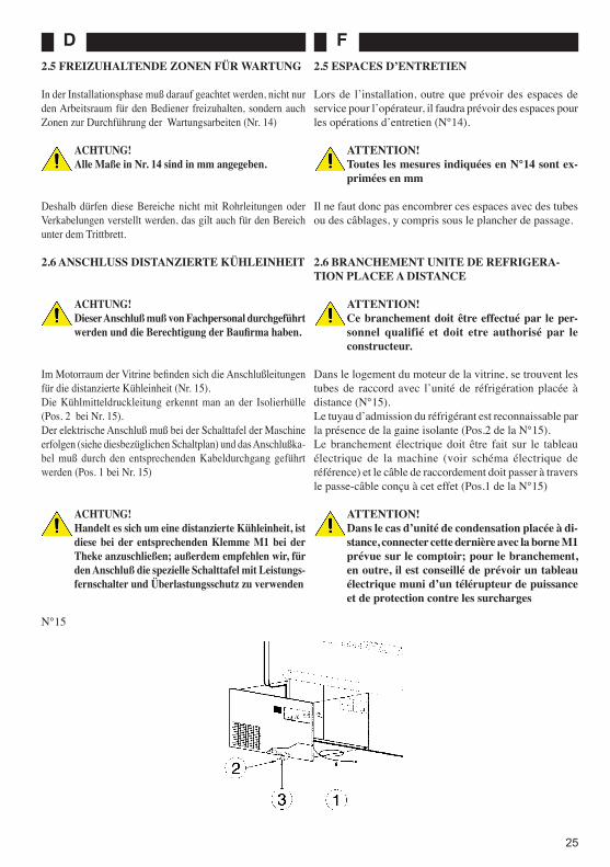
Nel vano motore della vetrina vi sono le tubazioni di allaccio per l'unità remota di refrigerazione (N°15).Il tubo di mandata del refrigerante è riconoscibile per la presenza del guaina isolante (Pos.2 di N°15).Il collegamento elettrico deve essere fatto sul quadro elettrico della macchina (vedi schema elettrico di riferi-mento) e il cavo di collegamento deve essere fatto passare attraverso l'apposito passacavo (Pos.1 di N°15)
ATTENZIONE!Nel caso di unità condensatrice remota collegare la stessa al morsetto M1 predisposto sul banco, inoltre per il collegamento si consiglia apposito quadro elettrico con teleruttore di potenza e protezione per i sovraccarichi
2.5 MAINTENANCE AREAS
During the installation stage, as well as work space for the operator, a sufficient area should be left for mainten-ance operations to be carried out (N° 14).
CAUTION!All measurements in N° 14 are shown in mm.
It is therefore important that these areas are not obstructed by pipes or wiring, even underneath the footboards.
2.6 HOW TO CONNECT A DETACHED REFRI-GERATING UNIT
CAUTION!This connection must be carried out by quali-fied personnel.and have the authorization of the constructor.
The motor compartment of the display unit contains the connection pipes for the detached refrigerating unit (N° 15).The inlet pipe for the refrigerant is recognisable by its insulation sheath (N° 15, Pos. 2).The electrical connection must be made on the electric control board of the machine (refer to the wiring diagram) and the connection cable must be passed through the rela-tive bushing (N° 15 Pos. 1).
CAUTION!If connecting a detached refrigerating unit, it must be connected to the terminal M1, which is fitted to the unit. Furthermore, we recommend fitting an electric control board and a remote switch with overload protection.
MISS 100 150 200
A(mm) 1000 1500 2000 A1(mm) 1000 1500 2000
N°14
AA1 700
700
FD
25
2.5 FREIZUHALTENDE ZONEN FÜR WARTUNG
In der Installationsphase muß darauf geachtet werden, nicht nur den Arbeitsraum für den Bediener freizuhalten, sondern auch Zonen zur Durchführung der Wartungsarbeiten (Nr. 14)
ACHTUNG!Alle Maße in Nr. 14 sind in mm angegeben.
Deshalb dürfen diese Bereiche nicht mit Rohrleitungen oder Verkabelungen verstellt werden, das gilt auch für den Bereich unter dem Trittbrett.
2.6 ANSCHLUSS DISTANZIERTE KÜHLEINHEIT
ACHTUNG!Dieser Anschluß muß von Fachpersonal durchgeführt werden und die Berechtigung der Baufirma haben.
Im Motorraum der Vitrine befinden sich die Anschlußleitungen für die distanzierte Kühleinheit (Nr. 15).Die Kühlmitteldruckleitung erkennt man an der Isolierhülle (Pos. 2 bei Nr. 15).Der elektrische Anschluß muß bei der Schalttafel der Maschine erfolgen (siehe diesbezüglichen Schaltplan) und das Anschlußka-bel muß durch den entsprechenden Kabeldurchgang geführt werden (Pos. 1 bei Nr. 15)
ACHTUNG!Handelt es sich um eine distanzierte Kühleinheit, ist diese bei der entsprechenden Klemme M1 bei der Theke anzuschließen; außerdem empfehlen wir, für den Anschluß die spezielle Schalttafel mit Leistungs-fernschalter und Überlastungsschutz zu verwenden
2.5 ESPACES DʼENTRETIEN
Lors de lʼinstallation, outre que prévoir des espaces de service pour lʼopérateur, il faudra prévoir des espaces pour les opérations dʼentretien (N°14).
ATTENTION!Toutes les mesures indiquées en N°14 sont ex-primées en mm
Il ne faut donc pas encombrer ces espaces avec des tubes ou des câblages, y compris sous le plancher de passage.
2.6 BRANCHEMENT UNITE DE REFRIGERA-TION PLACEE A DISTANCE
ATTENTION!Ce branchement doit être effectué par le per-sonnel qualifié et doit etre authorisé par le constructeur.
Dans le logement du moteur de la vitrine, se trouvent les tubes de raccord avec lʼunité de réfrigération placée à distance (N°15).Le tuyau dʼadmission du réfrigérant est reconnaissable par la présence de la gaine isolante (Pos.2 de la N°15).Le branchement électrique doit être fait sur le tableau électrique de la machine (voir schéma électrique de référence) et le câble de raccordement doit passer à travers le passe-câble conçu à cet effet (Pos.1 de la N°15)
ATTENTION!Dans le cas dʼunité de condensation placée à di-stance, connecter cette dernière avec la borne M1 prévue sur le comptoir; pour le branchement, en outre, il est conseillé de prévoir un tableau électrique muni dʼun télérupteur de puissance et de protection contre les surcharges
N°15

I GB
26
2.7 COLLEGAMENTO ELETTRICO
Prima di effettuare lʼinstallazione verificare lʼesistenza di un idoneo impianto di messa a terra come previsto dalle Norme Europee (EN).Controllare che la tensione di rete sia compatibile con le caratteristiche riportate sulla targa apposta sul lato opera-tore della vetrina (vedi N°5).
ATTENZIONE! Fluttuazioni di tensione maggiori del 10% della tensione nominale indicata sulla targa possono provocare danni permanenti al compressore ed alle altre apparecchiature elettromeccaniche che in tal caso non saranno coperti da garanzia.
Rispettare comunque eventuali norme nazionali per le installazioni elettriche. La vetrina è fornita completa di cavo di alimentazione elettrica a spina.
NOTA: E ̓opportuno installare un interruttore sulla linea di alimentazione elettrica alla presa predisposta per la vetrina .
2.8 NOTE AMBIENTALI
- ImballaggioNon gettare nella spazzatura eventuali parti dellʼimbal-lo della vetrina, ma selezionarli a seconda del tipo di materiale (Cartone, legno, acciaio, polietilene, ecc...) e smaltirli a seconda della normativa vigente nel paese di utilizzo della vetrina.
- Fine servizioAlla fine della vita della vetrina si dovrà:- Recuperare tutto il refrigerante dal circuito frigo;- Svuotarla di tutto lʼolio contenuto a qualsiasi titolo
nella stessa;- Togliere tutte le parti in gomma (es. O-ring, guarni-
zioni);- Smontare tutte le superfici vetrate;- Inviarla infine alla rottamazione.
2.7 ELECTRICAL CONNECTIONS
Before installing the unit, ensure that the earthing con-nections are in strict conformity with European Standards (EN).Check that mains voltage is compatible with the technical data on the plate fixed to the operatorʼs side of the display unit. (N°5).
CAUTION!Voltage fluctuations of more than 10% of the rated voltage shown on the plate can cause permanent damage to the compressor, as well as to other electrical and mechanical equip-ment, which in such circumstances will not be covered by the Guarantee.
In all cases, the applicable national standards for the instal-lation of electrical equipment should be respected.The display unit is supplied with feed cable and plug.
NOTE: We recommend that a switch be fitted to the mains plug socket of the display unit.
2.8 ENVIRONMENTAL MEASURES
- PackagingDo not discard any part of the unit packaging before sorting it according to the different types of material, (cardboard, wood, steel, polyethylene, etc.). Packaging should then be disposed of according to the applicable standards in force in the Country of use.
- End of ServiceAt the end of the display unitʼs useful life it is necessary to carry out the following:- Recover the refrigerant from the refrigerating circuit;- Empty out all oil contained in the unit;- Remove all rubber parts (e.g., O-ring, gaskets);- Dismantle all glass surfaces;- Send the unit for proper disposal.
FD
27
2.7 ELEKTRISCHER ANSCHLUSS
Bevor die Installation durchgeführt wird, muß das Bestehen einer geeigneten Erdungsanlage gemäß den Europanormen (EN) geprüft werden.Prüfen, ob die Netzspannung mit den Merkmalen auf dem Schild, das auf der Bedienerseite der Vitrine angebracht ist, vereinbar ist (siehe Nr.5).
ACHTUNG!Spannungsschwankungen von über 10% gegenüber der Nennspannung auf dem Schild können dauerhafte Schäden am Kompressor und anderen elektromecha-nischen Ausrüstungen verursachen, die nicht unter die Garantieleistungen fallen.
Eventuelle nationale Normen für Elektroinstallationen sind auf jeden Fall zu beachten.Die Vitrine wird mit Speisekabel und Stecker geliefert.
HINWEIS: es ist zweckmäßig, bei der Speiseleitung, die die Vitrine versorgt, einen Schalter zu instal-lieren.
2.8 HINWEISE ZUM SCHUTZ DER UMWELT
- VerpackungEventuelle Teile der Vitrinenverpackung dürfen nicht zum Müll gegeben werden, sondern müssen je nach Material aussortiert (Karton, Holz, Stahl, Polyäthylen usw....) und gemäß der im Verwendungsland gültigen Normen entsorgt werden.
- BetriebseinstellungWird die Vitrine nicht mehr verwendet, muß man:- das gesamte Kühlmittel aus dem Kühlkreis entfernen;- bei der gesamten Vitrine das Öl ablassen;- alle Teile aus Gummi entfernen (z.B. O-Ring, Dichtungen);- alle Glasflächen abmontieren;- die Vitrine verschrotten lassen.
2.7 BRANCHEMENT ELECTRIQUE
Avant de procéder à lʼinstallation, sʼassurer de lʼexistence dʼune installation adéquate de mise à la terre comme le prévoient les Normes Européennes (EN).Vérifier que la tension de réseau soit compatible avec les caractéristiques reportées sur la plaquette placée sur le côté service de la vitrine (voir N°5).
ATTENTION!Les fluctuations de tension dépassant 10% de la tension nominale indiquée sur la plaquette peuvent provoquer des dommages perma-nents au compresseur et aux autres appareils électromécaniques qui, dans ce cas, ne seront pas couverts par la garantie.
Il faut, quoi quʼil en soit, respecter les éventuelles normes nationales concernant les installations électriques. La vitrine est fournie accompagnée dʼun câble dʼalimen-tation électrique à fiche.
REMARQUE: Il est opportun dʼinstaller un in-terrupteur sur la ligne dʼalimentation électrique à la prise prévue pour la vitrine .
2.8 REMARQUES SUR LʼENVIRONNEMENT
- EmballageNe pas mettre les éventuelles parties de lʼemballage de la vitrine au rebut, mais les sélectionner selon le type de matériau (carton, bois, acier, polyéthylène, etc. ...), et les éliminer selon la réglementation en vigueur dans le Pays de destination de la machine.
- Fin de serviceAu terme de la durée de vie de la machine il faudra:- Récupérer tout le réfrigérant à lʼintérieur du circuit frigorifique;- Vider la machine de toute lʼhuile contenue dans celle-ci;- Retirer toutes les parties en caoutchouc (ex. joints tori-ques dʼétanchéité, garnitures);- Démonter toutes les surfaces vitrées;- Placer, enfin, la machine à la ferraille.

I GB
28
N°16
3 ESERCIZIO
3.2 AVVIAMENTO E REGOLAZIONE DELLA TEMPERATURA
Per poter eseguire lʼavviamento della vetrina si deve agire sul gruppo comandi che prevede (vedi N°16, 16A):A- INTERRUTTORE GENERALE VETRINA (Pos.1);B- INTERRUTTORE ACCENSIONE VETRINA
(Pos.2);C- INTERRUTTORE ACCENSIONE LUCI (Pos.3);D- INTERRUTTORE SBRINAMENTO MANUALE
(Pos.4);E- TASTO PER SETTAGGIO TEMPERATURA
(Pos.5);F- TASTO FRECCIA SU E FRECCIA GIU ̓ PER IM-
POSTAZIONE DELLA TEMPERATURA DELLA VETRINA (Pos.6).
G- DISPLAY (Pos.7).H- DEVIATORE RESISTENZA ANTICONDENSA
(Pos.8).I - INTERRUTTORE ILLUMINAZIONE OPZIONALE
FRONTALE (pos.9).
Effettuate le operazioni descritte in para.3.1, inserire lʼinterruttore sulla linea di alimentazione alla presa, quindi azionare lʼinterruttore Pos.1 per portare tensione alla vetrina.A questo punto possiamo avviare la vetrina premendo il pulsante di accensione (pos.2) ed eventualmente accendere lʼilluminazione del vano di esposizione.La temperatura di esercizio della vetrina viene già pre-impostata dalla casa.
3 OPERATION
3.2 START UP AND TEMPERATURE REGULA-TION
To start the unit, it is necessary to use the following con-trols (N°16, 16A):A- MAIN SWITCH OF THE DISPLAY CABINET
(Pos.1);B- SWITCH FOR THE IGNITIO OF THE DISPLAY
CABINET (Pos.2);C- SWITCH FOR THE LIGHTING OF THE LIGHTS
(Pos.3);D- HAND DEFROSTING SWITCH (Pos.4);E- SETTING KEY OF THE TEMPERATURES (Pos.5);F- INDICATOR KEY UP AND INDICATOR DOWN
FOR THE DISPLAY CABINET TEMPERATUREʼS SETTING (Pos.6).
G-DISPLAY (Pos.7).H- ANTICONDENSATE RESISTANCE SWITCH
(Pos.8).I - OPTIONAL FRONTAL ILLUMINATION SWITCH (pos.9).
Once the operations described in para. 3.1. have been fulfilled, put the switch on the feeding line to the intake, then turn on the switch Pos.1 in order to bring tension to the display cabinet.At this point it is possible to make the display cabinet start by pressing on the ignition Key (pos.2) and eventually turn on the lights of the exhibition room.The working temperature of the display cabinet has already been set by the company .
1
25
34
67
8 9
FD
29
3 BETRIEB
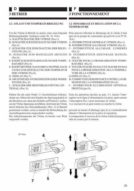
3.2 ANLAUF UND TEMPERATURREGELUNG
Um die Vitrine in Betrieb zu setzen, muss man folgende Bedienungsknöpfe betätigen (siehe Nr. 16, 16A):A- HAUPTSCHALTER DER VITRINE (Pos.1);B- SCHALTER ZUR EINSCHALTUNG DER VITRINE
(Pos.2);C- SCHALTER ZUR EINSCHALTUNG DER BELEU-
CHTUNG (Pos.3);D- SCHALTER ZUM MANUELLEN ABTAUEN
(Pos.4);E- KNOPF ZUR SICHTBARMACHUNG DER TEMPE-
RATUREN (Pos.5);F- KNOPF MIT PFEIL NACH OBEN UND PFEIL NACH
UNTEN ZUR EINSTELLUNG DER TEMPERATUR DER VITRINE (Pos.6).
G- DISPLAY (Pos.7).H- ABLEITER DES ANTIKONDENSWASSER-WIDER-
STANDS (Pos. 8).I – SCHALTER DER FRONTBELEUCHTUNG (OP-TIONAL) (Pos. 9).
Führen Sie die unter Punkt 3.1 beschriebenen Arbeitss-chritte aus, führen Sie den Schalter des Speisungskabels in die Steckdose ein, dann den Schalter auf Position 1 stellen, um der Vitrine Spannung zuzuführen. Jetzt kann die Vitrine durch Drücken des Einschaltknopfes (Pos. 2) in Betrieb genommen werden, sowie eventuell die Beleuchtung des Ausstellungsbereichs eingeschaltet werden.Die Arbeitstemperatur der Vitrine ist bereits vom Werk eingestellt worden.
3 FONCTIONNEMENT
3.2 DEMARRAGE ET REGULATION DE LA TEMPERATURE
Pour pouvoir effectuer le démarrage de la vitrine il faut agir sur le groupe de commandes qui prévoit (voir N°16, 16A):A- INTERRUPTEUR GENERALE VITRINE (Pos.1);B- INTERRUPTEUR ALLUMAGE VITRINE (Pos.2);C- INTERRUPTEUR ALLUMAGE LUMIERES
(Pos.3);D- INTERRUPTEUR DEGIVRAGE MANUEL
(Pos.4);E- TOUCHE POUR LA PROGRAMMATION TEMPE-
RATURES (Pos.5);F- TOUCHE FLECHE EN HAUT ET FLECHE EN BAS
POUR LA PROGRAMMATION DE LA TEMPERA-TURE DE LA VITRINE (Pos.6).
G-DISPLAY (Pos.7).H- COMMUTATEUR RESISTANCE CONTRE LA FOR-
MATION DE LA CONDEBSATION (Pos.8).I - INTERRUTEUR ILLUMINATION OPTIONAL
FRONTAL(pos.9).
Faire les opérations decrites au para. 3.1, insérer lʼinter-rupteur sur la ligne dʼalimentations à la prise, après tourner lʼinterrupteur Pos.1 pour tensionner la vitrine.A ce moment-là on peut mettre en marche la vitrine
pressant la touche dʼallumage (pos.2) et eventuellement allumer lʼillumination de la pièce dʼexposition.La temperature dʼexercise de la vitrine à déjà été program-mée en avance par la maison.
N°16A
56
6
7
4

I GB
30
N°17
Questa può essere in qualsiasi momento modificata nella seguente maniera (vedi fig.17):1- Con la vetrina accesa premere il pulsante SET per
alcuni secondi (pos.5);2- Il display delle temperature comincia a lampeggiare
(pos.7);3- premere il pulsante freccia giù se si vuole abbassare
la temperatura della vetrina (pos.6);4- premere il pulsante freccia su se si vuole aumentare
la temperatura della vetrina (pos.6a);5- Una volta impostato il valore desiderato, aspettare
che i numeri del display smettano di lampeggiare, a questo punto il nuovo valore della temperatura è stato memorizzato.
NOTA: Comunque per informazioni più detta-gliate sullʼuso del controllo fare riferimento al manuale specifico, allegato al presente;
NOTA: Il numero di sbrinamenti che la vetrina esegue durante le 24 ore sono 4 (valore impostato dalla casa costruttrice), comunque valutando le condizioni climatiche in cui opera la macchina si può sempre effettuare uno sbrinamento supple-mentare premendo il pulsante Pos.4.
NOTA: Il deviatore (pos.8) consente di far fun-zionare la resistenza antiappannamento nelle seguenti modalità:Posizione 1: la resistenza viene alimentata solo quando il compressore è funzionante;Posizione 2: la resistenza viene sempre ali-mentata.
ATTENZIONE!TENERE SEMPRE SOTTO CONTROLLO IL LIVELLO DELLA VASCHETTA DI SCARICO DELLA CONDENSA ED EVENTUALMENTE SVUOTARLA (N°17A).
It can be at any time changed as follows (see fig.17):1- When the display cabinet is on press the key SET for
some seconds (pos.5);2- The showing of the temperatures begins to blink
(pos.7);3- press the down indicator key in order to put the tem-
perature of the display cabinet (pos.6);4- press the up indicator key in order to increase the
temperature of the display cabinet (pos.6a);5- Once the value you want has been set, wait that the
numbers of the display stop blinking, at this moment the new value of the temperature has been memori-sed.
NOTE: Anyway for further detail about the control use do refer to the specific handbook that is here attached:
NOTE: The defrosting number that the display cabinet does during the 24 hours are 4 (value set by the company) , however after having checked the climatic conditions in which the machine works, it is possible to execute another defrosting pressing the key Pos.4.
NOTE: The switch (pos.8) allows the anti-fogging switch to function in the following ways :Position 1: the resistance is fed only when the compressor is functioning;Position 2: the resistance is continually fed.
WARNING!ALWAYS CHECK THE LEVEL OF THE DECHARGING TANK OF THE WATER CON-DENSATION AND IF NECESSARY DRAIN IT (N°17A).
56
6
7
8
21

FD
31
Diese kann jederzeit in folgender Weise verändert werden (siehe Abb.17):1- Bei eingeschalteter Vitrine den Knopf SET einige
Sekunden lang drücken (Pos.5);2- Das Temperaturdisplay beginnt zu blinken (Pos.7);3- den Knopf mit Pfeil nach unten drücken, wenn man
die Temperatur der Vitrine senken will (Pos.6);4- den Knopf mit Pfeil nach oben drücken, wenn man
die Temperatur der Vitrine erhöhen will (Pos.6a);5- Nach dem Einstellen des gewünschten Wertes warten
bis die Zahlen auf dem Display aufhören zu blinken; daraufhin ist der neue Temperaturwert gespeichert.
HINWEIS: Genauere Informationen bezüglich des Gebrauchs der Kontrollfunktionen können dem beiliegenden spezifischen Handbuch ent-nommen werden;
HINWEIS: Innerhalb von 24 Stunden führt die Vitrine 4 Abtauungsvorgänge aus (diese Anzahl ist vom Hersteller eingestellt worden); bei entsprechenden klimatischen Konditionen im Umfeld der Maschine kann eine zusätzliche Abtauung vorgenommen werden durch Drücken des Knopfes Pos.4.
HINWEIS: Der Ableiter (Pos. 8) ermöglicht die Funktion des Antibeschlag-Widerstandes auf folgende Weisen:Position 1: der Widerstand wird nur gespeist, wenn der Kompressor in Funktion ist;Position 2: der Widerstand wird immer gespeist.
ACHTUNG!HALTEN SIE STETS DAS NIVEAU DER KONDENSWASSERAUFFANGWANNE UNTER KONTROLLE UND LEEREN SIE SIE (N°17A).
On peut la changer dans nʼimporte quel moment dans la manière suivante (voir fig.17):1- Avec la vitrine allumée presser la touche SET pour
quelques secondes (pos.5);2- Le display des temperatures commence à clignoter
(pos.7);3- presser la touche flèche en bas si lʼon veut diminuer
la temperature de la vitrine (pos.6);4- presser la touche flèche en haut si lʼon veut augmenter
la temperature de la vitrine (pos.6a);5- Une fois programmée la valeur que lʼon veut, attendre
che les nombres du display arretent de clignoter, à ce moment-là la nouvelle temperature à déjà été memo-risée .
NOTE: De toute façon pour des informations plus dettaillées sur lʼutilisation du contrôle il faut se reférer au manuel spécifique ici allegué;
NOTE: Le nombre de degivrage que la vitrine fait pendant les 24 heures sont 4 (valeur program-mée de la maison contructrice), de toute façon en considerant les conditions climatiques dans lesquelles la machine marche on peut toujours faire un degivrage supplementaire en pressant la touche Pos.4.
NOTE : Le commutateur (pos.8) permet de faire fontionner la résistance antiternissement dans les manières suivantes :Position 1 : la résistance est alimentée seulement lorsque le compresseur est en fonction ;Position 2 : la résistance est toujours ali-mentée.
ATTENTION!CONTROLER TOUJOURS LE NIVEAU DU BAC DE DECHARGE DE LA CONDENSA-TION ET EVENTUELLEMENT LE VIDER (N°17A).
N°17A
4
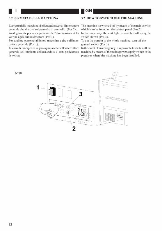
I GB
32
3.2 FERMATA DELLA MACCHINA
L̓ arresto della macchina si effettua attraverso l'interruttore generale che si trova sul pannello di controllo (Pos.2),Analogamente per lo spegnimento dell'illuminazione della vetrina agire sull'interruttore (Pos.3).Per togliere corrente all'intera macchina agire sull'inter-ruttore generale (Pos.1).In caso di emergenza si può agire anche sullʼinterruttore generale dellʼimpianto del locale dove e ̓stata posizionata la vetrina.
3.2 HOW TO SWITCH OFF THE MACHINE
The machine is switched off by means of the mains switch which is to be found on the control panel (Pos.2).In the same way, the unit light is switched off using the switch shown (Pos.3).To cut the current to the whole machine, turn off the general switch (Pos.1).In the event of an emergency, it is possible to switch off the machine by means of the mains power supply switch in the premises where the machine has been installed.
N°18
3
2
1
FD
33
3.2 STILLSETZEN DER MASCHINE
Das Stillsetzen der Maschine erfolgt mit Hilfe des Haupt-schalters, der sich auf dem Bedienfeld befindet (Pos. 2),Gleichermaßen erfolgt das Ausschalten der Vitrinenbeleuchtung mit Hilfe des Schalters (Pos.3).Um die Stromzufuhr der gesamten Maschine stillzule-gen, den Hauptschalter bedienen (Pos.1).Im Notfall kann auch der Hauptschalter der Elektroanlage des Raumes betätigt werden, in dem sich die Vitrine befindet.
3.2 ARRET DE LA MACHINE
Lʼarrêt de la machine sʼeffectue à travers lʼinterrup-teur général qui se trouve sur le panneau de contrôle (Pos.2).De la même façon, pour éteindre lʼéclairage de la vitrine, agir sur lʼinterrupteur (Pos.3).Enlever la corrent electrique à travers lʼinterrupteur général (Pos.1).En cas dʼurgence, il est possible dʼagir également sur lʼinterrupteur général de lʼinstallation du local où est installée la vitrine.

I GB
34
4 ROUTINE MAINTENANCE
4.1 PRELIMINARY SAFETY CHECKS
CAUTION! Before carrying out any cleaning or main-tenance operations, first disconnect the unit from the mains power supply!
To disconnect the unit from the mains power supply, the two switches found on the control panel (N°19, Pos.3 and 2) must be switched off, as must the switch fitted to the mains plug socket of the display unit. The unit must then be unplugged.
4.2 CLEANING THE CONDENSER
It is most important that the dust and dirt which collects on the condenser fins is removed every 20÷30 days, if the refrigerating circuit is to work efficiently. This should be carried out in the following manner (N°20):- Carry out the operations described in Section 4.1.- Remove the condenser protection grille by loosening the screws positioned at the grille perimeter.- With the help of a soft brush and a vacuum cleaner, remove the dust and dirt from the condenser fins.
CAUTION! Never use metal or very stiff tools to carry out this operation since they may bend the fins and in this way, affect the correct operation of the system.
- Replace the grille and screw back into place.- Reconnect the mains power supply.
4 MANUTENZIONE ORDINARIA
4.1 OPERAZIONI PRELIMINARI DI SICUREZZA
ATTENZIONE! Prima di effettuare qualsiasi operazione di manutenzione o pulizia è necessario scollegare lʼalimentazione elettrica!
Per effettuare lo scollegamento della alimentazione elet-trica si devono disinserire i due interruttori che si trovano sul pannello di controllo (N°19 Pos.3 e 2) e l'interruttore di linea alla presa della vetrina, dopo di che staccare la spina elettrica di alimentazione.
4.2 PULIZIA CONDENSATORE
Per mantenere in buona efficienza il circuito frigo è indi-spensabile, ogni 20÷30 giorni, rimuovere la polvere e lo sporco che si depositano sulle alette del condensatore.Procedere nella seguente maniera (N°20):- Eseguire le operazioni descritte in 4.1- Rimuovere la griglia di protezione del condensatore, svitando le viti di fissaggio sul perimetro.- Togliere la polvere e lo sporco presente nelle alette del condensatore usando una spazzola od un pennello e un aspirapolvere.
ATTENZIONE! Non usare arnesi metallici o comunque rigidi poi-ché potrebbero piegare le alette e compromettere il buon funzionamento dellʼimpianto.
- Riposizionare la griglia al suo posto e fissarla con le viti.- Ricollegare l'alimentazione elettrica.
N°19
3
2
1
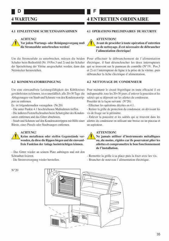
FD
35
N°20
4 WARTUNG
4.1 EINLEITENDE SCHUTZMASSNAHMEN
ACHTUNG! Vor jedem Wartungs- oder Reinigungsvorgang muß die Stromzufuhr unterbrochen werden!
Um die Stromzufuhr zu unterbrechen, müssen die beiden Schalter beim Bedienfeld (Nr. 19 Pos.3 und 2) und der Schalter der Speiseleitung der Vitrine ausgeschaltet werden; dann den Netzstecker herausziehen.
4.2 KONDENSATORREINIGUNG
Um eine einwandfreie Leistungsfähigkeit des Kühlkreises gewährleisten zu können, ist es unerläßlich, alle 20÷30 Tage die Ablagerungen von Staub und Schmutz von den Kondensatorrip-pen zu entfernen. Es ist folgendermaßen vorzugehen (Nr.20):- Die unter Punkte 4.1 beschriebenen Maßnahmen treffen.- Die äußeren Feststellschrauben beim Schutzgitter des Konden-sators entfernen und das Gitter abnehmen.- Staub und Schmutz auf den Kondensatorrippen mit Hilfe einer Bürste, eines Pinsels oder Staubsaugers entfernen.
ACHTUNG! Keine metallenen oder steifen Gegenstände ver-wenden, da diese die Rippen biegen und die einwand-freie Funktion der Anlage beeinträchtigen können.
- Das Gitter wieder an seinem Platz anbringen und mit den Schrauben fixieren.- Die Stromversorgung wieder herstellen.
4 ENTRETIEN ORDINAIRE
4.1 OPERATIONS PRELIMINAIRES DE SECURITE
ATTENTION! Avant de procéder à toute opération dʼentretien ou de nettoyage, il est nécessaire de débrancher lʼalimentation électrique!
Pour effectuer le débranchement de lʼalimentation électrique, il faut désenclencher les deux interrupteurs qui se trouvent sur le panneau de contrôle (N°19, Pos.3 et 2) et lʼinterrupteur de ligne à la prise de la vitrine, puis débrancher la fiche électrique dʼalimentation.
4.2 NETTOYAGE DU CONDENSEUR
Pour maintenir le circuit frigorifique en toute efficacité il est indispensable, tous les 20÷30 jours, dʼenlever la poussière et les saletés qui se déposent sur les ailettes du condenseur.Procéder de la façon suivante (N°20):- Effectuer les opérations décrites en 4.1.- Retirer la grille de protection du condenseur, en dévissant les vis de fixage sur le périmètre.- Enlever la poussière et les saletés qui se trouvent dans les ailettes du condenseur en utilisant une brosse ou un pinceau et un aspirateur.
ATTENTION! Ne jamais utiliser dʼinstruments métalliques ou, du moins, rigides car ils pourraient plier les ailettes et compromettre le bon fonctionnement de lʼinstallation.
- Remettre la grille à sa place puis la fixer avec les vis.- Brancher de nouveau lʼalimentation électrique.
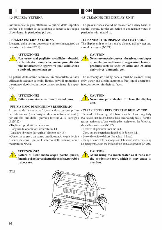
I GB
36
4.3 PULIZIA VETRINA
Giornalmente si può effettuare la pulizia delle superfici vetrate e lo scarico della vaschetta di raccolta dell'acqua di condensa, in particolare poi per:
- PULIZIA ESTERNO VETRINAL̓ esterno della vetrina deve essere pulito con acqua ed un detersivo delicato (N°21).
ATTENZIONE! Non usare mai pagliette metalliche, abrasivi, carta vetrata o simili e nemmeno prodotti chi-mici notoriamente aggressivi quali acidi, cloro e derivati, ammoniaca etc.
La pulizia delle antine scorrevoli in metacrilato va fatta utilizzando acqua e detersivi liquidi, privi di ammoniaca o sostanze alcoliche, in modo da non rovinare la super-ficie.
ATTENZIONE!Evitare assolutamente lʼuso di alcool puro.
- PULIZIA PIANO DI ESPOSIZIONE REFRIGERATOLʼinterno della vasca refrigerata deve essere pulito periodicamente ( si consiglia almeno settimanalmente), per cui alla fine della giornata lavorativa, si consiglia di (N°22):- Togliere i prodotti dalla vetrina .- Eseguire le operazioni descritte in 4.1- Lasciare sbrinare la vetrina (almeno per 1h)- Con una spugna o un panno umidi, usando acqua tiepida e senza detersivi, pulire l ̓ interno della vetrina, come mostrato in N°20a.
ATTENZIONE! Evitare di usare molta acqua poiché questa, finendo poi nella vaschetta di raccolta, potrebbe traboccare.
4.3 CLEANING THE DISPLAY UNIT
The glass surfaces should be cleaned on a daily basis, as should the tray for the collection of condensate water. In particular with regard to:
- CLEANING THE DISPLAY UNIT EXTERIORThe display unit exterior must be cleaned using water and a mild detergent (N° 21).
CAUTION! Never use metal scourers, abrasives, sandpaper or similar, or well-known, aggressive chemical products such as acids, chlorine and chlorine derivatives, ammonia, etc.
The methacrylate sliding panels must be cleaned using only water and alcohol/ammonia-free liquid detergents, in order not to ruin their surfaces.
CAUTION!Never use pure alcohol to clean the display unit.
- CLEANING THE REFRIGERATED DISPLAY TOPThe inside of the refrigerated basin must be cleaned regularly (we advise that this be done at least on a weekly basis). For this reason, at the end of one working day each week, the following should be carried out (N° 22):- Remove all products from the unit.- Carry out the operations described in Section 4.1.- Leave the unit to defrost (for at least 1 hour).- Using a damp cloth or sponge and lukewarm water containing no detergents, clean the inside of the unit, as shown in N° 20a.
CAUTION! Avoid using too much water as it runs into the condensate tray, which it may cause to overflow.
N°21

FD
37
4.3 REINIGUNG VITRINE
Die Reinigung der Glasflächen und das Entleeren der Konden-swasserauffangwanne können täglich durchgeführt werden; im einzelnen:
- AUSSENREINIGUNG VITRINEDie Außenseite der Vitrine muß mit Wasser und einem sanften Reinigungsmittel gesäubert werden (Nr. 21).
ACHTUNG! Niemals Metallwolle, Scheuermittel, Glaspapier oder ähnliches, sowie bekanntermaßen aggressive Chemikalien, wie Säuren, Chlor und Nebenprodukte, Ammoniak usw. verwenden.
Die Reinigung der Schiebetüren aus Methacrylat muß unter Verwendung von Wasser und flüssigen Reinigungsmitteln, ohne Ammoniak oder alkoholische Substanzen, erfolgen, da diese die Oberfläche beschädigen würden.
ACHTUNG!Auf keinen Fall reinen Alkohol verwenden.
- REINIGUNG GEKÜHLTE AUSSTELLUNGSFLÄCHEDie Innenseite der Kühlwanne muß periodisch gereinigt wer-den (wir empfehlen, mindestens einmal pro Woche); am Ende eines Arbeitstag wird empfohlen folgendermaßen vorzugehen (Nr. 22):- die Produkte aus der Vitrine nehmen.- Die unter Punkt 4.1 beschriebenen Maßnahmen treffen.- Die Vitrine abtauen lassen (mindestens 1h).- Die Innenseite der Vitrine mit einem Schwamm oder feuchten Tuch reinigen, siehe Abbildung 20a; das Wasser soll lauwarm sein und es dürfen keine Reinigungsmittel verwendet werden.
ACHTUNG! Nicht zu viel Wasser verwenden, da dieses in die Auf-fangwanne gelangt und überlaufen könnte.
4.3 NETTOYAGE DE LA VITRINE
Le nettoyage des surfaces vitrées peut être effectué quotidiennement ainsi que le déchargement de la cuve de récupération de lʼeau de condensation. Puis, en par-ticulier, pour le:- NETTOYAGE EXTERNE DE LA VITRINEL̓ extérieur de la vitrine doit être nettoyé avec de lʼeau et un détergent délicat (N°21).
ATTENTION! Ne jamais utiliser de pailles de fer, dʼabrasifs, du papier de verre ou autres, ni des produits chimi-ques manifestement agressifs tels que les acides, le chlore et dérivés, lʼammoniaque, etc.
Le nettoyage des panneaux coulissants en méthacrylate doit être effectué en utilisant de lʼeau et des détergents liquides, sans ammoniaque ou solutions alcooliques de façon à ne pas abîmer la surface.
ATTENTION!Eviter absolument lʼusage dʼalcool pur.
- NETTOYAGE DU PLAN DʼEXPOSITION REFRIGE-RELʼintérieur de la vitrine doit être nettoyé périodiquement (il est conseillé de le faire au moins toutes les semaines), raison pour laquelle il est conseillé, au terme de la journée de travail, de (N°22):- Retirer les produits de la vitrine.- Effectuer les opérations indiquées en 4.1.- Laisser le temps à la vitrine de se dégivrer (au moins 1h).- A lʼaide dʼune éponge ou dʼun chiffon humide, et en utilisant de lʼeau tiède sans détergents, nettoyer lʼintérieur de la vitrine, comme illustré en N°20a.
ATTENTION! Eviter dʼutiliser trop dʼeau car, finissant dans la cuve de récupération, elle pourrait déborder.
N°22

I GB
38
4.4 SBRINAMENTI
- SBRINAMENTO AUTOMATICOCome è stato già segnalato la macchina è stata dotata di termostato che esegue 2 o 4 sbrinamenti in 24h a.
ATTENZIONE!Svuotare la vaschetta di recupero dell'acqua di condensa giornalmente (N°23) o ogni volta ce ne fosse la necessità.
- SBRINAMENTO MANUALEPer particolari condizioni ambientali gli sbrinamenti in automatico potrebbero non essere sufficienti, per cui può essere necessario iniziare uno sbrinamento aggiuntivo tra-mite il pulsante di sbrinamento manuale (Pos.4 N°24).
ATTENZIONE!Prima di effettuare uno sbrinamento manuale controllare il livello della vaschetta di raccolta dell'acqua di sbrinamento e nel caso fosse ne-cessario, svuotarla (N°23).
- SBRINAMENTO CON FERMO MACCHINAOgni 30 giorni è preferibile effettuare uno sbrinamento prolungato ( di almeno 12 ore) con fermo macchina, in modo da eliminare ogni residuo di ghiaccio sull'evapo-ratore.
ATTENZIONE!Svuotare la vaschetta di recupero dell'acqua di condensa (N°24).
4.4 DEFROSTING
- AUTOMATIC DEFROSTAs already explained, the machine has been fitted with a thermo-stat to carry out 2 or 4 defrost cycles over a 24-hour period.
CAUTION!Empty the condensate water tray every day. (N°23).
MANUALLY OPERATED DEFROSTIn specific working environments, it is possible that the automatic defrost cycles are insufficient. Should this be the case, it may be necessary to carry out an additional defrost cycle using the push-button for manual defrost (N°24 Pos. 4).
CAUTION!Before carrying out a manually operated defrost cycle, check the level of the defrost water in the tray and empty if necessary (N°23).
- DEFROSTING WHEN THE MACHINE IS SWITCHED OFFA prolonged defrost cycle with the machine switched off should be carried out every thirty days (for at least 12 hours), in order to remove all traces of ice from the evaporator.
CAUTION!Empty the water from the condensate tray (N°24).
N°23
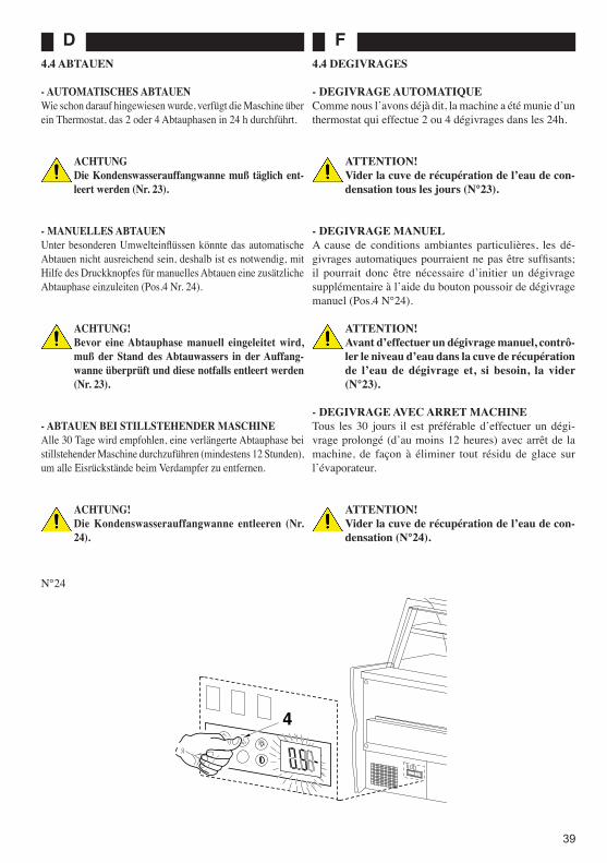
FD
39
4.4 ABTAUEN
- AUTOMATISCHES ABTAUENWie schon darauf hingewiesen wurde, verfügt die Maschine über ein Thermostat, das 2 oder 4 Abtauphasen in 24 h durchführt.
ACHTUNGDie Kondenswasserauffangwanne muß täglich ent-leert werden (Nr. 23).
- MANUELLES ABTAUENUnter besonderen Umwelteinflüssen könnte das automatische Abtauen nicht ausreichend sein, deshalb ist es notwendig, mit Hilfe des Druckknopfes für manuelles Abtauen eine zusätzliche Abtauphase einzuleiten (Pos.4 Nr. 24).
ACHTUNG!Bevor eine Abtauphase manuell eingeleitet wird, muß der Stand des Abtauwassers in der Auffang-wanne überprüft und diese notfalls entleert werden (Nr. 23).
- ABTAUEN BEI STILLSTEHENDER MASCHINEAlle 30 Tage wird empfohlen, eine verlängerte Abtauphase bei stillstehender Maschine durchzuführen (mindestens 12 Stunden), um alle Eisrückstände beim Verdampfer zu entfernen.
ACHTUNG!Die Kondenswasserauffangwanne entleeren (Nr. 24).
4.4 DEGIVRAGES
- DEGIVRAGE AUTOMATIQUEComme nous lʼavons déjà dit, la machine a été munie dʼun thermostat qui effectue 2 ou 4 dégivrages dans les 24h.
ATTENTION!Vider la cuve de récupération de lʼeau de con-densation tous les jours (N°23).
- DEGIVRAGE MANUELA cause de conditions ambiantes particulières, les dé-givrages automatiques pourraient ne pas être suffisants; il pourrait donc être nécessaire dʼinitier un dégivrage supplémentaire à lʼaide du bouton poussoir de dégivrage manuel (Pos.4 N°24).
ATTENTION!Avant dʼeffectuer un dégivrage manuel, contrô-ler le niveau dʼeau dans la cuve de récupération de lʼeau de dégivrage et, si besoin, la vider (N°23).
- DEGIVRAGE AVEC ARRET MACHINETous les 30 jours il est préférable dʼeffectuer un dégi-vrage prolongé (dʼau moins 12 heures) avec arrêt de la machine, de façon à éliminer tout résidu de glace sur lʼévaporateur.
ATTENTION!Vider la cuve de récupération de lʼeau de con-densation (N°24).
N°24
4

I GB
40
5 MANUTENZIONE STRAORDINARIA
5.1 OPERAZIONI PRELIMINARI DI SICUREZZA
ATTENZIONE! Tutte le operazione di manutenzione straor-dinaria o correttiva devono essere effettuate da personale specializzato ed autorizzato dal costruttore
ATTENZIONE! Prima di effettuare qualsiasi operazione di manutenzione è necessario scollegare lʼalimen-tazione elettrica!
Per effettuare lo scollegamento della alimentazione elet-trica si devono disinserire i due interruttori che si trovano sul pannello di controllo (N°25 Pos.5 e 6) e l'interruttore di linea alla presa della vetrina, dopo di che staccare la spina elettrica di alimentazione.
5.2 SOSTITUZIONE DELLE SUPERFICI VETRATE
- Sostituzione vetro frontale
ATTENZIONE!Eseguire questa operazione in due persone.
Per lo smontaggio del vetro, è sufficiente: - Aprire il vetro; - Allentare i grani alla base della cerniera (N°26); - Sfilare il vetro e sostituirlo con il nuovo.
ATTENZIONE!Quando si inserisce il nuovo vetro nella cerniera, avvitare bene tutti i grani senza forzarli
5 SPECIAL MAINTENANCE
5.1 PRELIMINARY SAFETY CHECKS
CAUTION! All corrective and special maintenance opera-tions must be carried out by qualified personnel and have the authorization of the constructor.
CAUTION! Before carrying out any maintenance opera-tions, first disconnect the unit from the mains power supply!
To disconnect the unit from the mains power supply, the two switches found on the control panel (N° 25 Pos. 5 and 6) must be switched off, as must the switch fitted to the mains plug socket of the display unit. The unit must then be unplugged.
5.2 REPLACING THE GLASS SURFACES
- How to replace the front panel in glass
CAUTION! This operation requires two people.
To remove the glass front panel it is sufficient to:- Open the glass panel;- Loosen the grub screws at the base of the hinge (N°26);- Slide out the glass panel and replace it with the new one.
CAUTION!After inserting the new panel into the hinge, tighten the grub screws well without forcing them.
N°25
3
2
1

FD
41
5 ENTRETIEN EXTRAORDINAIRE
5.1 OPERATIONS PRELIMINAIRES DE SECURITE
ATTENTION! Toute opération dʼentretien extraordinaire ou correctif doit être effectuée par le personnel qua-lifié et doit etre authorisé par le constructeur.
ATTENTION! Avant dʼeffectuer toute opération dʼentretien, il faut débrancher lʼalimentation électrique!
Pour débrancher lʼalimentation électrique, il faut dé-senclencher les deux interrupteurs qui se trouvent sur le panneau de contrôle (N°25 Pos.5 et 6) et lʼinterrupteur de ligne à la prise de la vitrine, puis débrancher la fiche électrique dʼalimentation.
5.2 REMPLACEMENT DES SURFACES VITREES
- Remplacement de la vitre frontale
ATTENTION!Effectuer cette opération à deux.
Pour le démontage de la vitre il suffit de: - Ouvrir la vitre; - Desserrer les vis sans tête à la base de la charnière (N°26); - Enlever la vitre en la faisant glisser et la remplacer avec une nouvelle vitre.
ATTENTION! Lors de lʼintroduction de la nouvelle vitre dans la charnière, sʼassurer de bien visser toutes les vis sans tête, sans les forcer.
5 AUSSERORDENTLICHE WARTUNG
5.1 EINLEITENDE SCHUTZMASSNAHMEN
ACHTUNG! Alle außerordentlichen oder korrektiven Wartungs-vorgänge müssen von Fachpersonal durchgeführt werden und die Berechtigung der Baufirma haben.
ACHTUNG! Vor jedem Wartungsvorgang muß die Stromzufuhr unterbrochen werden!
Um die Stromzufuhr zu unterbrechen, müssen die beiden Schalter beim Bedienfeld (Nr. 25 Pos. 5 und 6) und der Schalter der Speiseleitung der Vitrine ausgeschaltet werden; dann den Netzstecker herausziehen.
5.2 AUSTAUSCH VON GLASFLÄCHEN
- Austausch Frontscheibe
ACHTUNG!Dieser Vorgang ist von zwei Personen durch-zuführen.
Zum Demontieren der Scheibe genügt es: - die Scheibe zu öffnen; - die Zapfen an der Scharnierbasis zu lockern (N°26); - die Scheibe zu entnehmen und durch eine neue zu ersetzen.
ACHTUNG!Beim Einsetzen der neuen Scheibe in das Scharnier, ist darauf zu achten, daß die Zapfen fest -aber nicht übermäßig - angezogen werden.
N°26
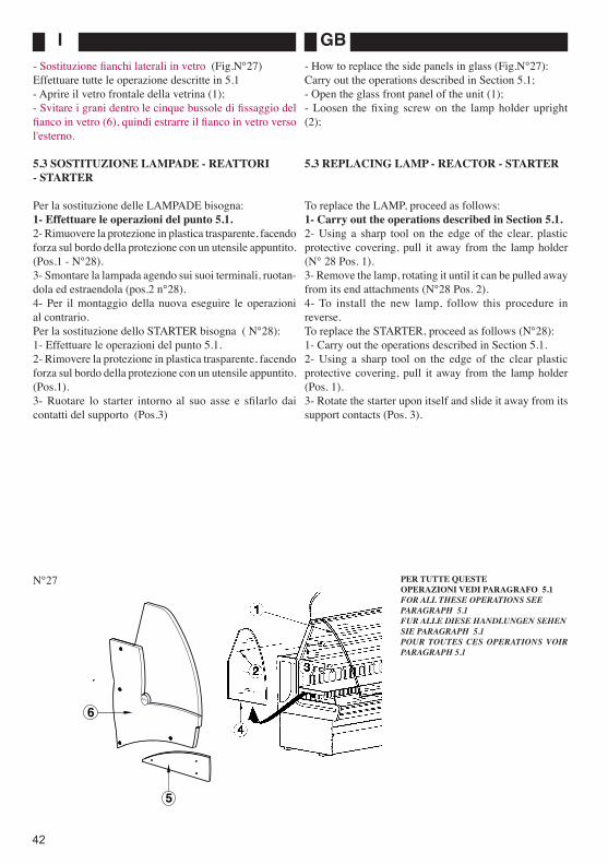
I GB
42
- Sostituzione fianchi laterali in vetro (Fig.N°27)Effettuare tutte le operazione descritte in 5.1- Aprire il vetro frontale della vetrina (1);- Svitare i grani dentro le cinque bussole di fissaggio del fianco in vetro (6), quindi estrarre il fianco in vetro verso l'esterno.
5.3 SOSTITUZIONE LAMPADE - REATTORI - STARTER
Per la sostituzione delle LAMPADE bisogna:1- Effettuare le operazioni del punto 5.1.2- Rimuovere la protezione in plastica trasparente, facendo forza sul bordo della protezione con un utensile appuntito. (Pos.1 - N°28).3- Smontare la lampada agendo sui suoi terminali, ruotan-dola ed estraendola (pos.2 n°28).4- Per il montaggio della nuova eseguire le operazioni al contrario.Per la sostituzione dello STARTER bisogna ( N°28):1- Effettuare le operazioni del punto 5.1.2- Rimovere la protezione in plastica trasparente, facendo forza sul bordo della protezione con un utensile appuntito. (Pos.1).3- Ruotare lo starter intorno al suo asse e sfilarlo dai contatti del supporto (Pos.3)
- How to replace the side panels in glass (Fig.N°27):Carry out the operations described in Section 5.1;- Open the glass front panel of the unit (1);- Loosen the fixing screw on the lamp holder upright (2);
5.3 REPLACING LAMP - REACTOR - STARTER
To replace the LAMP, proceed as follows:1- Carry out the operations described in Section 5.1.2- Using a sharp tool on the edge of the clear, plastic protective covering, pull it away from the lamp holder (N° 28 Pos. 1).3- Remove the lamp, rotating it until it can be pulled away from its end attachments (N°28 Pos. 2).4- To install the new lamp, follow this procedure in reverse.To replace the STARTER, proceed as follows (N°28):1- Carry out the operations described in Section 5.1.2- Using a sharp tool on the edge of the clear plastic protective covering, pull it away from the lamp holder (Pos. 1).3- Rotate the starter upon itself and slide it away from its support contacts (Pos. 3).
N°27 PER TUTTE QUESTE OPERAZIONI VEDI PARAGRAFO 5.1FOR ALL THESE OPERATIONS SEE PARAGRAPH 5.1FUR ALLE DIESE HANDLUNGEN SEHEN SIE PARAGRAPH 5.1POUR TOUTES CES OPERATIONS VOIR PARAGRAPH 5.1
SIFA
5
6

FD
43
N°28
- Austausch seitliche Scheiben (Abb.N°27)Die unter Punkt 5.1 beschriebenen Maßnahmen treffen.- Die Frontscheibe der Vitrine öffnen (1);- Die Feststellschraube beim Deckenlampenträger lösen (2);
5.3 AUSTAUSCH LAMPEN - DROSSELSPULEN - STARTER
Für den Austausch der LAMPEN ist folgendermaßen vor-zugehen:1- die unter Punkt 5.1 beschriebenen Maßnahmen treffen;2- die durchsichtige Schutzabdeckung entfernen, indem man mit einem spitzen Werkzeug beim Abdeckungsrand Kraft ausübt (Pos. 1 - Nr.28).3- Die Lampe abmontieren: man wirkt auf die Endstücke ein, dreht die Lampe und entnimmt sie (Pos.2 - Nr.28).4- Bei der Montage der neuen Lampe die Vorgänge in umgeke-hrter Reihenfolge durchführen.Für den Austausch des STARTERS ist folgendermaßen vor-zugehen ( Nr. 28):1- Die unter Punkt 5.1 beschriebenen Maßnahmen treffen.2- Die durchsichtige Schutzabdeckung entfernen, indem man mit einem spitzen Werkzeug beim Abdeckungsrand Kraft ausübt (Pos. 1).3- Den Starter um die eigene Achse drehen und aus den Kontakten der Halterung herausziehen (Pos. 3).
- Remplacement des vitres latérales (Fig.N°27)Effectuer les opérations indiquées en 5.1- Ouvrir la vitre frontale de la vitrine (1);- Dévisser la vis de fixage au montant du plafonnier (2);
5.3 REMPLACEMENT LAMPE-REACTEUR- STARTER
Pour le remplacement de la LAMPE, il faut:1- Effectuer les opérations du paragraphe 5.1.2- Retirer la protection transparente en plastique, en forçant sur le bord de la protection à lʼaide dʼun outil pointu. (Pos.1, N°28).3- Démonter la lampe en agissant sur ses bornes en la faisant tourner et en lʼextrayant (Pos.2, N°28).4- Pour le montage de la nouvelle lampe, effectuer les opérations dans le sens inverse.
Pour le remplacement du STARTER, il faut ( N°28):1- Effectuer les opérations du paragraphe 5.1.2- Retirer la protection transparente en plastique, en forçant sur le bord de la protection avec un outil pointu (Pos.1).3- Faire tourner le starter autour de son axe et le faire glisser hors des contacts du support (Pos.3).

I GB
44
4- Per il montaggio dello STARTER eseguire le operazioni al contrario.
Per la sostituzione del REATTORE bisogna (Fig.N°29):1- Effettuare le operazioni del punto 5.1.2- Rimovere il pannello posteriore di protezione (Pos.1).3- Rimuovere i collegamenti elettrici del reattore.4- Rimuovere le viti di fissaggio del reattore (Pos.2), e sostituirlo.5- Per il montaggio del REATTORE eseguire le operazioni al contrario.
ATTENZIONE! Installando il nuovo reattore fare riferimento allo schema elettrico per i collegamenti elettrici.
5.4 SOSTITUZIONE RESISTENZA ANTICONDENSA
Per la sostituzione della resistenza anticondensa del vetro anteriore (Pos.2 Fig.N°30):1- Effettuare le operazioni del punto 5.1.2- Rimuovere i vetri frontali come spiegato in Parag.5.23- Rimovere la protezione in alluminio (Pos.1).4- Staccare i Faston di collegamento della resistenza, e sostituirla con una nuova (Pos.3).5- Per il montaggio della nuova eseguire le operazioni al contrario.
4- To install the new starter, follow this procedure in reverse.
To replace the REACTOR, proceed as follows (Fig.N°29):1- Carry out the operations described in Section 5.1.2- Remove the rear protection panel (Pos.1)3- Disconnect the wiring connections of the reactor;4- Remove the reactor fixing screws (Pos. 2) and place the new reactor into position.5- To complete the installation of the new reactor, follow this procedure in reverse.
CAUTION! When installing a new reactor, always refer to the wiring diagram when making the electrical connections.
5.4 REPLACING THE ANTI-CONDENSATE RESISTOR
To replace the glass front panel anti-condensate resistor, proceed as follows (Pos.2 Fig.N°30):1- Carry out the operations described in Section 5.1.2- Remove the glass front panels, as explained in Sec-tion 5.2.3- Remove the aluminium protective covering (Pos. 1).4- Disconnect the Faston connections and replace the resistor (Pos. 3).5- To install the new resistor, follow this procedure in reverse.
N°29PER TUTTE QUESTE OPERAZIONI VEDI PARAGRAFO 5.1FOR ALL THESE OPERATIONS SEE PARAGRAPH 5.1FUR ALLE DIESE HANDLUNGEN SEHEN SIE PARAGRAPH 5.1POUR TOUTES CES OPERATIONS VOIR PARAGRAPH 5.1
2
1
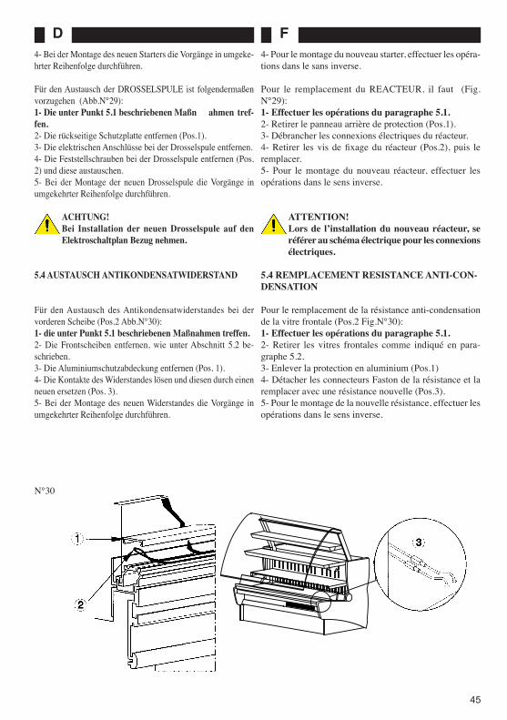
FD
45
N°30
4- Bei der Montage des neuen Starters die Vorgänge in umgeke-hrter Reihenfolge durchführen.
Für den Austausch der DROSSELSPULE ist folgendermaßen vorzugehen (Abb.N°29):1- Die unter Punkt 5.1 beschriebenen Maßn ahmen tref-fen.2- Die rückseitige Schutzplatte entfernen (Pos.1).3- Die elektrischen Anschlüsse bei der Drosselspule entfernen.4- Die Feststellschrauben bei der Drosselspule entfernen (Pos. 2) und diese austauschen.5- Bei der Montage der neuen Drosselspule die Vorgänge in umgekehrter Reihenfolge durchführen.
ACHTUNG! Bei Installation der neuen Drosselspule auf den Elektroschaltplan Bezug nehmen.
5.4 AUSTAUSCH ANTIKONDENSATWIDERSTAND
Für den Austausch des Antikondensatwiderstandes bei der vorderen Scheibe (Pos.2 Abb.N°30):1- die unter Punkt 5.1 beschriebenen Maßnahmen treffen.2- Die Frontscheiben entfernen, wie unter Abschnitt 5.2 be-schrieben.3- Die Aluminiumschutzabdeckung entfernen (Pos. 1).4- Die Kontakte des Widerstandes lösen und diesen durch einen neuen ersetzen (Pos. 3).5- Bei der Montage des neuen Widerstandes die Vorgänge in umgekehrter Reihenfolge durchführen.
4- Pour le montage du nouveau starter, effectuer les opéra-tions dans le sans inverse.
Pour le remplacement du REACTEUR, il faut (Fig.N°29):1- Effectuer les opérations du paragraphe 5.1.2- Retirer le panneau arrière de protection (Pos.1).3- Débrancher les connexions électriques du réacteur.4- Retirer les vis de fixage du réacteur (Pos.2), puis le remplacer.5- Pour le montage du nouveau réacteur, effectuer les opérations dans le sens inverse.
ATTENTION! Lors de lʼinstallation du nouveau réacteur, se référer au schéma électrique pour les connexions électriques.
5.4 REMPLACEMENT RESISTANCE ANTI-CON-DENSATION
Pour le remplacement de la résistance anti-condensation de la vitre frontale (Pos.2 Fig.N°30):1- Effectuer les opérations du paragraphe 5.1.2- Retirer les vitres frontales comme indiqué en para-graphe 5.2.3- Enlever la protection en aluminium (Pos.1)4- Détacher les connecteurs Faston de la résistance et la remplacer avec une résistance nouvelle (Pos.3).5- Pour le montage de la nouvelle résistance, effectuer les opérations dans le sens inverse.

I GB
46
a) chiudere lʼinterruttore automatico (o sostituire il fusibile).
b) inserire lʼinterruttore principale.
c) se la temperatura a cui il termo-stato è tarato è superiore a quella già esistente nella vasca di esposizione, ovviamente il compressore non parte; controllare la messa a punto della temperatura voluta (v. punto 3.2) e quella esistente.d) aprire lʼinterruttore principale, togliendo corrente a tutta la vetrina; pulire le alette del condensatore, come detto al punto 4.2; ridare quindi corrente alla vetrina.
a) provvedere allo sbrinamento come indicato:- Staccare lʼinterruttore principale per 10/12 ore in modo da permette-re lo scongelamento dellʼevaporatore (punto 4.4).b) pulire il condensatore come indi-cato al punto 4.2.c) chiamare un esperto frigorista per individuare la causa della perdita di gas, eliminarla e solo dopo di questo effettuare la nuova carica con la qualità e la quantità di gas indicate nella targhetta.d) in queste condizioni la vetrina non funziona; togliere la vetrina dalle correnti dʼaria e/o dalla luce diretta del sole.e) rimuovere tutto ciò che ostacola un regolare flusso dʼaria al con-densatore.
f) chiamare un esperto frigorista per la sostituzione del termostato.
a) non cʼè corrente perché è saltato lʼinterruttore automatico (o, se cʼera, un fusibile).b) lʼinterruttore principale è disin-serito.c) termostato regolato troppo alto.
d) sovraccarico al compressore per carente condensazione dovuta a con-densatore intasato da polvere o altro.
a) evaporatore ostruito dal ghiaccio.
b) condensatore ostruito da polvere o altro.c) mancanza di gas (l'evaporatore non sbrina completamente).
d) il banco è esposto a correnti dʼaria o alla luce diretta del sole.
e) al condensatore non arriva il regola-re flusso dʼaria (qualche oggetto, fogli di carta, stracci etc. ostruisce le griglie in cui passa lʼaria del condensatore).f) termostato non funzionante rego-larmente (con l'impianto refrigerante perfettamente funzionante il termosta-to interviene prima del raggiungimen-to della temperature impostata).
1) Il compressore non entra in funzione.
2) Temperatura della zona di esposi-zione non sufficientemente bassa.
6 ANOMALIE DI FUNZIONAMENTOPROBLEMA PROBABILI CAUSE POSSIBILI RIMEDI
I
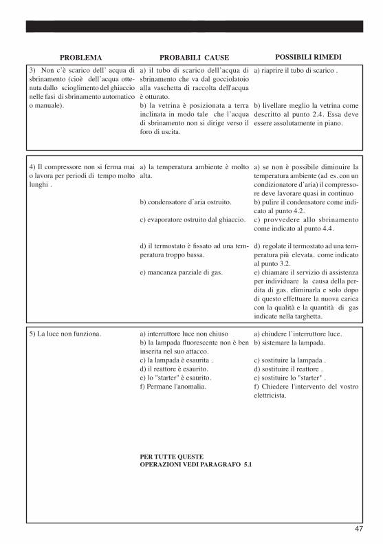
FD
47
a) riaprire il tubo di scarico .
b) livellare meglio la vetrina come descritto al punto 2.4. Essa deve essere assolutamente in piano.
a) se non è possibile diminuire la temperatura ambiente (ad es. con un condizionatore dʼaria) il compresso-re deve lavorare quasi in continuob) pulire il condensatore come indi-cato al punto 4.2.c) provvedere allo sbrinamento come indicato al punto 4.4.
d) regolate il termostato ad una tem-peratura più elevata, come indicato al punto 3.2.e) chiamare il servizio di assistenza per individuare la causa della per-dita di gas, eliminarla e solo dopo di questo effettuare la nuova carica con la qualità e la quantità di gas indicate nella targhetta.
a) chiudere lʼinterruttore luce.b) sistemare la lampada.
c) sostituire la lampada .d) sostituire il reattore .e) sostituire lo "starter" .f) Chiedere l'intervento del vostro elettricista.
a) il tubo di scarico dellʼacqua di sbrinamento che va dal gocciolatoio alla vaschetta di raccolta dell'acqua è otturato.b) la vetrina è posizionata a terra inclinata in modo tale che lʼacqua di sbrinamento non si dirige verso il foro di uscita.
a) la temperatura ambiente è molto alta.
b) condensatore dʼaria ostruito.
c) evaporatore ostruito dal ghiaccio.
d) il termostato è fissato ad una tem-peratura troppo bassa.
e) mancanza parziale di gas.
a) interruttore luce non chiusob) la lampada fluorescente non è ben inserita nel suo attacco.c) la lampada è esaurita .d) il reattore è esaurito.e) lo "starter" è esaurito.f) Permane l'anomalia.
3) Non cʼè scarico dell ̓ acqua di sbrinamento (cioè dellʼacqua otte-nuta dallo scioglimento del ghiaccio nelle fasi di sbrinamento automatico o manuale).
4) Il compressore non si ferma mai o lavora per periodi di tempo molto lunghi .
5) La luce non funziona.
PROBLEMA PROBABILI CAUSE POSSIBILI RIMEDI
PER TUTTE QUESTE OPERAZIONI VEDI PARAGRAFO 5.1

I GB
48
PROBLEM
1) The compressor will not start
2) Display top temperature is not sufficiently low
LIKELY CAUSES
a) there is no electric current because the automatic circuit breaker (or fuse, if applicable), has been triggeredb) the main switch has not been activatedc) the thermostat has been set too high
d) compressor overload due to lack of condensation caused by condenser being blocked by dust or other
a) evaporator blocked by ice
b) condenser blocked by dust or other c) lack of gas (the evaporator does not defrost correctly)
d) the counter is exposed to draughts or to direct sunlight
e) the proper air flow is not reaching the condenser (something, e.g. sheets of paper, cloths, etc. is blocking the condenser air passage grille)f) the thermostat is not functioning regularly (with the refrigerating system in perfect working order, the thermostat intervenes before the set
temperature has been reached)POSSIBILE SOLUTIONS
a) turn off the automatic circuit breaker (or replace the fuse)
b) enable the main switch c) if the set temperature of the ther-mostat is above that of the display top, the compressor will not start up; check the setting of the required temperature (see Section 3.2) with that of the current temperature
d) enable the main switch to cut off the power supply to the display unit; clean the condenser fins, as described in Section 4.2; then reconnect the power to the display unit
a) carry out defrosting as follows:- Turn off the main switch for 10-12 hours in order to permit the evapora-tor to defrost (see Section 4.4)b) clean the condenser as indicated in Section 4.2c) call a qualified refrigeration en-gineer to detect the cause of the gas leak . When this has been solved, refill the system in accordance with the quality and quantity of gas shown on the plate d) the display unit will not function in these circumstances: remove it from any draughts and/or from direct sunlighte) remove anything which is pre-venting regular air flow to the condenser
f) call a qualified refrigeration engi-neer to replace the thermostat
6 TROUBLESHOOTING
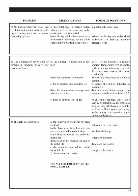
FD
49
POSSIBLE SOLUTIONS
a) unblock the outlet pipe
b) level the display unit as described in Section 2.4. The unit must be perfectly level
a) if it is not possible to reduce ambient temperature (for example, with an air conditioning system), the compressor must work almost continuallyb) clean the condenser as shown in Section 4.2c) defrost the unit as indicated in Section 4.4d) set the thermostat to a higher tem-perature, as indicated in Section 3.2
e) call the Technical Assistance Service to detect the cause of the gas leak and only after having solved the problem, refill the system according to the quality and quantity of gas shown on the plate
a) turn off the light switch
b) adjust the lamp
c) replace the lamp
d) replace the reactor
e) replace the starter
PROBLEM
3) No disposal of defrost water (that is, of the water obtained from melt-ing ice during automatic or manual defrosting cycles)
4) The compressor never stops or remains in function for very long periods of time
5) The light does not work
LIKELY CAUSES
a) the outlet pipe for defrost water, which goes from the water drip to the condensate tray, is blockedb) the display unit has been incorrectly levelled (i.e., unevenly) and the water cannot flow towards the outlet hole
a) the ambient temperature is too high
b) the air condenser is blocked
c) the evaporator is blocked by ice
d) the thermostat is set at a temperature which is too low
e) there is a partial lack of gas
a) the light switch circuit has not been enabledb) the fluorescent lamp has not been correctly inserted into the fittingsc) the lamp has reached the end of its useful lifed) the reactor has reached the end of its useful lifee) the starter has reached the end of its useful lifef) the malfunction persists
FOR ALL THESE OPERATIONS SEE PARAGRAPH 5.1
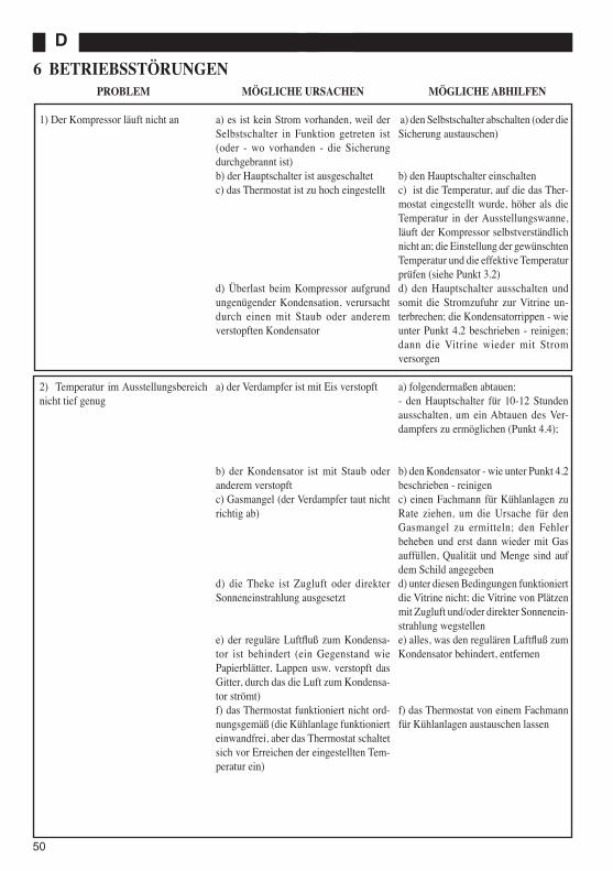
I GB
50
MÖGLICHE ABHILFEN
a) den Selbstschalter abschalten (oder die Sicherung austauschen)
b) den Hauptschalter einschaltenc) ist die Temperatur, auf die das Ther-mostat eingestellt wurde, höher als die Temperatur in der Ausstellungswanne, läuft der Kompressor selbstverständlich nicht an; die Einstellung der gewünschten Temperatur und die effektive Temperatur prüfen (siehe Punkt 3.2)d) den Hauptschalter ausschalten und somit die Stromzufuhr zur Vitrine un-terbrechen; die Kondensatorrippen - wie unter Punkt 4.2 beschrieben - reinigen; dann die Vitrine wieder mit Strom versorgen
a) folgendermaßen abtauen:- den Hauptschalter für 10-12 Stunden ausschalten, um ein Abtauen des Ver-dampfers zu ermöglichen (Punkt 4.4);
b) den Kondensator - wie unter Punkt 4.2 beschrieben - reinigenc) einen Fachmann für Kühlanlagen zu Rate ziehen, um die Ursache für den Gasmangel zu ermitteln; den Fehler beheben und erst dann wieder mit Gas auffüllen, Qualität und Menge sind auf dem Schild angegebend) unter diesen Bedingungen funktioniert die Vitrine nicht; die Vitrine von Plätzen mit Zugluft und/oder direkter Sonnenein-strahlung wegstellene) alles, was den regulären Luftfluß zum Kondensator behindert, entfernen
f) das Thermostat von einem Fachmann für Kühlanlagen austauschen lassen
PROBLEM
1) Der Kompressor läuft nicht an
2) Temperatur im Ausstellungsbereich nicht tief genug
6 BETRIEBSSTÖRUNGEND
MÖGLICHE URSACHEN
a) es ist kein Strom vorhanden, weil der Selbstschalter in Funktion getreten ist (oder - wo vorhanden - die Sicherung durchgebrannt ist)b) der Hauptschalter ist ausgeschaltetc) das Thermostat ist zu hoch eingestellt
d) Überlast beim Kompressor aufgrund ungenügender Kondensation, verursacht durch einen mit Staub oder anderem verstopften Kondensator
a) der Verdampfer ist mit Eis verstopft
b) der Kondensator ist mit Staub oder anderem verstopftc) Gasmangel (der Verdampfer taut nicht richtig ab)
d) die Theke ist Zugluft oder direkter Sonneneinstrahlung ausgesetzt
e) der reguläre Luftfluß zum Kondensa-tor ist behindert (ein Gegenstand wie Papierblätter, Lappen usw. verstopft das Gitter, durch das die Luft zum Kondensa-tor strömt)f) das Thermostat funktioniert nicht ord-nungsgemäß (die Kühlanlage funktioniert einwandfrei, aber das Thermostat schaltet sich vor Erreichen der eingestellten Tem-peratur ein)

FD
51
PROBLEM
3) Das Abtauwasser fließt nicht ab (das heißt, das Wasser, das beim Schmelzen des Eises während der automatischen oder manuellen Abtauphasen entsteht)
4) Der Kompressor steht nie still oder arbeitet über sehr lange Zeitspannen hin
5) Das Licht funktioniert nicht
MÖGLICHE URSACHEN
a) das Abtauwasser-Abflußrohr, das von der Tropfrinne zur Auffangwanne führt, ist verstopftb) die Vitrine ist schief auf dem Boden positioniert und das Abtauwasser kann de-shalb nicht zur Auslauföffnung gelangen
a) die Raumtemperatur ist sehr hoch
b) der Luftkondensator ist verstopft
c) der Verdampfer ist mit Eis verstopft
d) das Thermostat ist auf eine zu niedrige Temperatur eingestellt
e) teilweises Fehlen von Gas
a) der Lichtschalter ist ausgeschaltetb) die Fluoreszenzlampe ist bei den An-schlüssen nicht richtig eingesetztc) die Lampe ist unbrauchbard) die Drosselspule ist unbrauchbare) der “Starter” ist unbrauchbarf) die Störung kann nicht behoben wer-den
MÖGLICHE ABHILFEN
a) das Abflußrohr wieder freimachen
b) die Vitrine besser ausrichten, siehe Beschreibung Punkt 2.4. Die Vitrine muß vollkommen eben sein
a) kann die Raumtemperatur nicht verringert werden (z.B. mit einer Kli-maanlage), muß der Kompressor fast ständig arbeitenb) den Kondensator - wie unter Punkt 4.2 beschrieben - reinigenc) abtauen, wie unter Punkt 4.4 be-schrieben
d) das Thermostat auf eine höhere Temperatur einstellen, wie unter Punkt 3.2 beschriebene) den Kundendienst rufen, um die Ur-sache für den Gasmangel zu ermitteln; den Fehler beheben und erst dann wieder mit Gas auffüllen, Qualität und Menge sind auf dem Schild angegeben
a) den Lichtschalter einschaltenb) die Lampe richtig anbringen
c) die Lampe austauschend) die Drosselspule austauschene) den “Starter” austauschenf) einen Elektriker zu Rate ziehen
FUR ALLE DIESE HANDLUNGEN SEHEN SIE PARAGRAPH 5.1

I GB
52
PROBLEME
1) Le compresseur ne démarre pas
2) Température de la zone dʼexposi-tion non suffisamment basse
SOLUTIONS POSSIBLES
a) enclencher lʼinterrupteur automati-que (ou remplacer le fusible)
b) enclencher lʼinterrupteur prin-cipalc) si la température à laquelle le thermostat a été réglé est supérieure à celle déjà existante dans lʼespace dʼexposition le compresseur ne dé-marre pas; vérifier la mise au point de la température désirée (v. paragraphe 3.2) et celle existanted) désenclencher lʼinterrupteur prin-cipal en coupant le courant de toute la vitrine; nettoyer les ailettes du condenseur, comme indiqué au paragraphe 4.2; redonner ensuite le courant électrique à la vitrine
a) procéder au dégivrage comme suit:- Débrancher lʼinterrupteur principal pendant 10/12 heures de façon à permettre la décongélation de lʼéva-porateur (paragraphe 4.4);b) nettoyer le condenseur comme indiqué au paragraphe 4.2c) appeler un expert frigoriste pour déterminer la cause de la fuite de gaz, éliminer la cause, puis procéder au rechargement avec la qualité et la quantité de gaz indiquées sur la plaquetted) dans ces conditions, la vitrine ne fonctionne pas; placer la vitrine hors dʼatteinte des courants dʼair et/ou de la lumière directe du soleile) enlever tout ce qui est susceptible dʼempêcher un flux régulier dʼair vers le condenseur
f) appeler un expert frigoriste pour le remplacement du thermostat
F6 ANOMALIES DE FONCTIONNEMENT
CAUSES PROBABLES
a) absence de courant car lʼinter-rupteur automatique a sauté (ou un fusible, sʼil y en avait un)b) lʼinterrupteur principal est désen-clenchéc) régulation trop élevée du ther-mostat
d) surcharge au compresseur à cause de la condensation insuffisante due au condenseur bouché par des poussières ou autre
a) évaporateur obstrué par la glace
b) condenseur obstrué par la poussière ou autrec) manque de gaz (lʼévaporateur ne dégivre pas correctement)
d) le comptoir est exposé à des cou-rants dʼair ou à la lumière directe du soleil
e) le flux dʼair normal nʼarrive pas au condenseur (quelque objet, feuilles de papier, chiffons, etc. obstrue les grilles à travers lesquelles passe lʼair du condenseur)f) thermostat ne fonctionnant pas régulièrement (avec lʼinstallation de réfrigération parfaitement fonction-nante, le thermostat intervient avant que la température programmée ait été atteinte)

FD
53
PROBLEME
3) L̓ eau de dégivrage ne sʼévacue pas (à savoir lʼeau obtenue à partir de la fonte de la glace durant les cycles de dégivrage automatique ou manuel)
4) Le compresseur ne sʼarrête jamais ou il travaille pendant des périodes de temps très longues
5) La lumière ne fonctionne pas
SOLUTIONS POSSIBLES
a) libérer le conduit dʼévacuation
b) niveler correctement la vitrine comme indiqué au paragraphe 2.4. Elle doit être absolument à niveau
a) sʼil est impossible de diminuer la température ambiante (par ex, en présence dʼun conditionneur dʼair) le compresseur doit travailler presque de façon continueb) nettoyer le condenseur comme indiqué au paragraphe 4.2c) procéder au dégivrage comme indiqué au paragraphe 4.4
d) régler le thermostat à une tempéra-ture plus élevée, comme indiqué au paragraphe 3.2e) appeler le service après-vente pour déterminer la cause de la fuite de gaz, éliminer la cause, puis procéder au rechargement avec la qualité et la quantité de gaz indiquées sur la plaquette
a) enclencher lʼinterrupteur lumièreb) positionner correctement la lam-pe
c) remplacer la lampe d) remplacer le réacteur e) remplacer le starter f) demander lʼintervention de votre électricien
POUR TOUTES CES OPERATIONS VOIR PARAGRAPH 5.1
CAUSES PROBABLES
a) le conduit dʼévacuation de lʼeau de dégivrage qui va de lʼégouttoir à la cuve de récupération de lʼeau est obstrué.b) la vitrine a été positionnée au sol de façon inclinée, ce qui empêche lʼeau de se diriger vers la bonde
a) la température ambiante est trop élevée
b) le condenseur dʼair est obstrué
c) lʼévaporateur est obstrué par la glace
d) le thermostat est établi à une tem-pérature trop basse
e) manque partiel de gaz
a) interrupteur lumière non enclen-chéb) la lampe fluorescente nʼest pas cor-rectement introduite dans sa prisec) la lampe est morte d) le réacteur est morte) le starter est mortf) lʼanomalie demeure

I GB
54
7 CATALOGO RICAMBI
Indice delle tavole
TAV. 1 SCHEMA ELETTRICO
INDICAZIONI PER L'ORDINAZIONE DELLE PARTI DI RICAMBIO
Per le ordinazioni delle parti di ricambio devono essere comunicate le seguenti indicazioni:- Tipo di macchina- Denominazione del pezzo- Numero di codice del pezzo- Quantità occorrente
7 REPLACEMENT PARTS CATALOGUE
Contents
TAB. 1 WIRING DIAGRAM
HOW TO ORDER REPLACEMENT PARTS
When ordering replacement parts, the following informa-tion must be given:- Machine Model- Part Description- Part Code Number- Quantity

FD
55
7 ERSATZTEILKATALOG
Tafelverzeichnis
TAFEL 1 SCHALTPLAN
HINWEISE ZUR BESTELLUNG VON ERSATZTEILEN
Bei der Bestellung von Ersatzteilen müssen folgende Angaben gemacht werden:- Maschinentyp- Bezeichnung des Teiles- Kodenummer des Teiles- benötigte Menge
7 CATALOGUE DES PIECES DETACHEES
Index des Tableaux
TAB. 1 SCHEMA ELECTRIQUE
INSTRUCTIONS POUR LA COMMANDE DES PIECES DETACHEES
Pour les commandes des pièces détachées, les indications suivantes doivent être communiquées:- Type de machine- Désignation de la pièce- Numéro de code de la pièce- Quantité nécessaire

I GB
56
TAV.
1
SCH
EMA
ELE
TTR
ICO