V. 006 MINDY -...
84
V. 006 A6-A6F A700F Centrale elettronica di controllo per cancelli a due ante A6-A6F A700F Electronic control unit for 2-winged gates A6-A6F A700F Centrale électronique de contrôle pour portails à deux battants A6-A6F A700F Elektronische Steuerzentrale für Zweiflügeltore A6-A6F A700F Central electrónica de control para verjas de dos hojas I GB F D E QUESTO LIBRETTO È DESTINATO SOLO ALL'INSTALLATORE. L'installazione dovrà essere effettuata solamente da personale professionalmente qualificato in conformità a quanto previsto dalla legge n° 46 del 5 marzo 1990 e successive modifiche ed integrazioni e nel pieno rispetto delle norme UNI 8612. MINDY
Transcript of V. 006 MINDY -...
V. 006
A6-A6FA700F
Centraleelettronica dicontrollo percancelli a dueante
A6-A6FA700F
Electroniccontrol unit for2-wingedgates
A6-A6FA700F
Centraleélectroniquede contrôlepour portails àdeux battants
A6-A6FA700F
ElektronischeSteuerzentralefürZweiflügeltore
A6-A6FA700F
Centralelectrónica decontrol paraverjas de doshojas
I GB F D E
QUESTO LIBRETTO È DESTINATO SOLO ALL'INSTALLATORE.L'installazione dovrà essere effettuata solamente da personale professionalmente qualificato in conformità a quanto previsto dallalegge n° 46 del 5 marzo 1990 e successive modifiche ed integrazioni e nel pieno rispetto delle norme UNI 8612.
MINDY

2

AVVISO IMPORTANTE:
La centrale descritta nel presente fascicolo è destinata al comando di uno o due attuatori elettromeccanici per l’automazione diporte o cancelli. Ogni altro uso è improprio e quindi vietato dalle normative vigenti.
E’ nostro dovere ricordare che eseguite delle operazioni su impianti di macchine classificate nella categoria dei: “Cancelli e porteautomatiche” quindi considerati particolarmente “pericolosi”. E’ vostro compito renderli “Sicuri” per quanto sia ragionevolmentepossibile!
L’installazione e gli interventi di manutenzione devono essere eseguiti solo da personale qualificato ed esperto,seguendo le migliori indicazioni dettate dalla “Regola d’arte” ed in conformità a quanto previsto dalle seguenti leggi, norme italianeo direttive europee:
• Norma UNI 8612 (Cancelli e portoni motorizzati: criteri costruttivi e dispositivi di protezione contro gli infortuni)
• DPR N°46 del 5/03/1990 (Norme per la sicurezza degli impianti elettrici, personale abilitato)
• Dlgs N°459/96 del 24/07/96 (Recepimento direttiva 89/392 CEE, Direttiva Macchine)
• Dlgs N°615/96 del 12/11/96 (Recepimento direttiva 89/336 CEE, Direttiva sulla Compatibilità Elettromagnetica)
• Dlgs N°626/96 del 26/11/96 (Recepimento direttiva 93/68 CEE, Direttiva Bassa Tensione)
Nella progettazione e realizzazione dei propri prodotti, Nice, rispetta (per quanto compete alle apparecchiature) tutte questenormative, è fondamentale però che anche l’installatore (per quanto compete agli impianti) prosegua nel rispetto scrupoloso dellemedesime norme.
Personale non qualificato o non a conoscenza delle normative applicabili alla categoria dei “Cancelli e porte automatiche”:Deve assolutamente astenersi dall’ eseguire installazioni ed impianti
Chi esegue impianti senza rispettare tutte le normative applicabili:E’ responsabile di eventuali danni che l’impianto potrà causare!
INDICE:
Guida rapida Pag. 41 Introduzione 61.1 Descrizione 6 2 Istruzioni per l’installazione 72.1 Installazione 72.2 Schema dei collegamenti 82.3 Descrizione dei collegamenti 92.4 Note sui collegamenti 103 Collaudo 113.1 Regolazioni 133.2 Modi di funzionamento 144 Programmazione 144.1 Funzioni programmabili 144.2 Descrizione delle funzioni 15
Accessorio : Scheda espansioni PIU’ 17Caratteristiche tecniche della centrale 18
Italiano
3
Il presente manuale è destinato solamente al personale tecnico qualificato per l'installazione.Nessuna informazione contenuta nel presente fascicolo può essere considerata interessante per l'utilizzatore finale!
Questo fascicolo è allegato agli articoli A6, A6F e A700F e non deve essere utilizzato per prodotti diversi!

GUIDA RAPIDA: Non installare la centrale senza aver letto tutte le istruzioni!
Prima di iniziare l’installazione verificare la robustezza e la consistenza meccanica dell’anta, il rispetto dei franchi di sicurezza edelle distanze minime. Valutare con particolare attenzione i dispositivi di sicurezza da applicare ed installare sempre un dispositivodi arresto d’emergenza vale a dire arresto di categoria 0.
Dopo aver eseguito un’attenta analisi dei rischi, sarà possibile installare la centrale, gli attuatori, i relativi elementi di comando(selettore a chiave o pulsantiere) e di sicurezza (arresto di emergenza, fotocellule, costole sensibili e lampeggiante), poi eseguirei collegamenti elettrici secondo il seguente schema:
Fig. 1
Le parti evidenziate sono diverse tra le versioni A6 , A6F e A700F
Gli ingressi dei contatti di tipo NC (Normalmente Chiuso), se non usati, vanno ponticellati, se piú di uno vanno posti in SERIE tradi loro; gli ingressi dei contatti di tipo NA (Normalmente Aperto) se non usati vanno lasciati liberi, se piú di uno vanno posti inPARALLELO tra di loro. I contatti devono essere assolutamente di tipo meccanico e svincolati da qualsiasi potenziale, non sonoammessi collegamenti a stadi tipo “PNP”, “NPN”, “Open Collector” ecc. ecc.
Si ricorda che vi sono delle normative precise da rispettare in modo rigoroso sia per quanto riguarda la sicurezza degliimpianti elettrici che per quanto riguarda i cancelli automatici.
Sbloccare i motoriduttori agendo sull’apposita chiave e verificare che l’anta si possa muovere senza particolari sforzi per tutta lasua corsa.
Portare tutti i dip-switch delle funzioni in posizione “Off” così il funzionamento è manuale in pratica a tasto premuto.
Italiano
4
CH
IUD
E
AP
RE
PA
SS
O P
AS
SO
FO
TO
1
FO
TO
ALT
SP
IA C
.A.
CO
MU
NE
24 Vac ( S
ER
VIZ
I )
Max 200 m
A
FIN
EC
OR
SA
AP
RE
2
FIN
EC
OR
SA
CH
IUD
E 2
FIN
EC
OR
SA
AP
RE
1
FIN
EC
OR
SA
CH
IUD
E 1
CO
MU
NE
FO
TO
TE
ST
( TX
FO
TO
)
24Vac, M
ax 100 mA
ELE
TT
RO
SE
RR
AT
UR
A
MO
TO
RE
2 CH
IUD
E
MO
TO
RE
2 CO
MU
NE
MO
TO
RE
2 AP
RE
MO
TO
RE
1 CH
IUD
E
MO
TO
RE
1 CO
MU
NE
MO
TO
RE
1 AP
RE
LUC
Y 230 V
acM
ax 100 W
LINE
A 230 V
ac "N"
TE
RR
A I
LINE
A 230 V
ac "L"
12 Vac, M
AX
25 W
MIC
RO
PR
OC
ES
SO
RE
PR
OG
RA
MM
AT
O
CH
AP
P.P
FO
TO
1
FO
TO
ALT
FC
A 2
FC
C 2
FC
A 1
FC
C 1
TR
AS
FO
R.
SE
CO
ND
.
TR
AS
FO
RM
.P
RIM
AR
IO
FUSETLM
TL
OK
FC
F FP
TP44
43
42
41
TRA
ANT.
RADIO
FUNZIONI 1-10 FUNZIONI 11-20
2° Ch
TRC500mA
FUSE
M12 2
M2
5 AF
1 2 3 4 5 6 7 8 9 10 11 12 13 14 15 16 17 18 19 20 21 22 23 24 25 26 27 28 29 30
RELE'COMUNE
RELE'SPUNTO
RELE'APRE/CHIUDE
RADIO
PIU'
•
•

Alimentare la centrale, verificare che tra morsetti 1-2 e 1-3 vi siano 230 Vca e che sui morsetti 21-22 vi siano 24 Vca; i LED postisugli ingressi di contatti NC devono accendersi ed il led OK dovrà lampeggiare alla frequenza di 1 al secondo.
Se installati i finecorsa, nella versione A700F controllare la corrispondenza dei quattro led FCA1, FCA2 FCC1 e FCC2, quandole ante sono chiuse devono spegnersi solo i due FCC, quando sono aperte devono spegnersi solo i due FCA.
Con le ante a metà della corsa in modo che possano muoversi liberamente nei due sensi di marcia, dare un breve impulso dicomando sull’ingresso APRE oppure sul PASSO-PASSO se si tratta della prima manovra dopo che la centrale è stata alimentata.Ora se l’anta non si è mossa nel senso di apertura occorre spegnere l’alimentazione elettrica quindi scambiare i collegamenti deimotori sui morsetti 6-8 oppure 9-11; infine riprovare se il senso di rotazione è corretto.
Provare ad eseguire un’intera manovra fino al raggiungimento dei punti di arresto meccanici o all’intervento dei finecorsa, provarepoi la manovra contraria.
La centrale incorpora un limitatore di coppia come previsto dalle normative UNI 8612 ediz. 89, a seconda delle versioni, regolarela FORZA con l’apposito trimmer oppure il commutatore sul trasformatore in modo che nel punto esterno dell’anta la spinta nonsuperi i 150 N (circa 15 Kg).
Se si desidera selezionare un movimento semiautomatico o automatico, occorre regolare il trimmer TEMPO LAVORO in modoche vi sia un margine di 2-3 Sec. sul tempo necessario per il movimento.
Solo se si è selezionato il modo automatico, regolare a piacere il trimmer TEMPO PAUSA.
Sulla centrale di comando sono presenti due trimmer per la regolazione del TEMPO RITARDO APERTURA e per il TEMPORITARDO CHIUSURA. Se richiesto regolare il ritardo in apertura in modo che le ante non si urtino durante il movimento e regolareil tempo ritardo chiusura affinchè la seconda anta si chiuda sovrapponendosi alla prima
Impostare i dip-switch delle FUNZIONI nel modo desiderato:
Switch 1-2: Off Off = Movimento “Manuale” cioè Uomo PresenteOn Off = Movimento “Semiautomatico”Off On = Movimento “Automatico” cioè Chiusura Automatica On On = Movimento “Automatico + Chiude Sempre”
Switch 3 On = Funzionamento Condominiale < Non disponibile in modo Manuale>Switch 4 On = PrelampeggioSwitch 5 On = Richiudi subito dopo Foto < solo in modo Automatico >Switch 6 On = Foto1 anche in aperturaSwitch 7 On = Partenza graduale < Funzione sconsigliata su motoriduttori METRO >Switch 8 On = Fermata gradualeSwitch 9 On = Colpo d’arieteSwitch 10 On = Luce di cortesia su lampeggiante
Solo nella versione A700F è presente un secondo gruppo di dip-switch con altre funzioni:
Switch 11 On = Funzione posizionamento < solo con l’utilizzo dei finecorsa >Switch 12 On = Lampeggiante anche in Pausa < solo in modo Automatico >Switch 13 On = Mantenimento pressioneSwitch 14 On = Spia C.A. con lampeggio proporzionaleSwitch 15 On = Attivazione FototestSwitch 16 On = Foto e Foto1 anche in aperturaSwitch 17 On = Foto e Foto1 ad inizio manovra di aperturaSwitch 18 On = Salta STOP in apre Switch 19 On = Salta STOP in chiudeSwitch 20 On = CHIUDE diventa APRE PEDONALE
Ricordiamo che alcune funzioni sono possibili solo in determinati casi, altre sono eseguite solo dopo specifici eventi, verificare lenote tra i caratteri “<>” presenti dopo la descrizione della funzione.
Infine provare le varie manovre possibili con le funzioni appena inserite; valutare con particolare attenzione l’efficacia deidispositivi di sicurezza e dell’arresto di emergenza.
Informare accuratamente l’utilizzatore finale sulla modalità d’uso del cancello automatico, sulla pericolosità residua, sulla modalitàdi sblocco manuale in caso di mancanza dell’energia elettrica, sulla necessità di una manutenzione accurata e costante inparticolare sulla necessità di un controllo periodico dei dispositivi di sicurezza e dei limitatori di coppia.
Italiano
5
•
•
•
•
•
•
•
•
•
•
•

1) INTRODUZIONE:
La centrale elettronica è utilizzabile per comandare il movimento di cancelli e porte automatiche, può essere collegata ad attuatorielettromeccanici dotati di motori asincroni monofase funzionanti con tensione di 230 Vac, ad esempio i modelli PLUTO PL 4000o METRO ME 3000 prodotti da Nice.
Il presente manuale di istruzioni si riferisce a più versioni della stessa centrale, le varie versioni si differenziano per una diversacompletezza delle funzioni programmabili e degli ingressi disponibili oltre ad un diverso metodo usato per il controllo della forzadegli attuatori:
A6 : Versione base, regolazione di forza elettronica a parzializzazione di faseA6F : Versione base, regolazione di forza elettromeccanica con autotrasformatore commutabileA700F : Versione completa, regolazione di forza elettromeccanica con autotrasformatore commutabile
La centrale permette azionamenti in modo “manuale”, “semiautomatico” oppure “automatico”; durante il movimento vengonocontrollati i consensi dai dispositivi di sicurezza (ingressi ALT, FOTO, FOTO1) nella versione A700F dei limiti del movimentovengono verificati mediante finecorsa, mentre nella versione A6 il movimento è a tempo.Dispone di sofisticate funzioni di tipo logico che vanno dalla “Memoria del movimento” fino alla “Richiudi subito dopo Foto”passando per la “Chiudi sempre” e di particolari funzioni di tipo operativo “Partenza graduale”, “Fermata graduale”Nella versione A700F, con l’inserimento della scheda espansioni modello “PIU’ “, si ampliano ancora di più le funzioni attraversoaltri ingressi ed altre uscite.Tutte le centrali sono predisposte per l’inserimento della vasta gamma di ricevitori radio prodotti da Nice,
Nel progetto sono state adottate le piú avanzate tecniche per garantire la massima immunità nei confronti dei disturbi, la maggioreflessibilità d’uso e la più vasta scelta di funzioni programmabili.
1.1) DESCRIZIONE:
Vista la particolarità del prodotto e l’uso di tecniche non paragonabili ad altri prodotti similari, prima di iniziare con l’installazionedella centrale ed eseguire i collegamenti è opportuna una breve descrizione degli elementi più importanti presenti sulla scheda.
Fig. 2
1: Trasformatore di alimentazione (solo A6)2: Innesti per autotrasformatore esterno (solo A6F o A700F)3: Fusibile 500 mA rapido su alimentazione 24 Vac4: Innesto per scheda RADIO 5: Trimmer di regolazione dei tempi 6: Morsettiera Antenna ed uscita 2º canale RADIO7: Dip-switch per la selezione delle funzioni8: Innesto per scheda PIU’ (solo A700F)9: Led di segnalazione dello stato degli ingressi10: Morsettiera ingressi sicurezze e comandi11: Morsettiera ingressi finecorsa (solo A700F)12: Morsettiera uscite elettroserratura e Fototest (solo A700F)13: Morsettiera uscite lampeggiante e motori14: Morsettiera alimentazione 230 Vac15: Fusibile 5 A rapido su alimentazione 230 Vac16: Led OK 17: Trimmer di regolazione della forza18: Ponticello FC per finecorsa normalmente aperti
Il led OK (16), ha il compito di segnalare il corretto funzionamento della logica interna deve lampeggiare alla cadenza di unsecondo ed indica che il microprocessore interno è attivo ed è in attesa di comandi. Quando c’è una variazione dello stato sugliingressi (10 - 11) o dei dip-switch delle funzioni (7) viene generato un doppio lampeggio veloce, questo anche se la variazionenon provoca effetti immediati. Quando la centrale è alimentata le spie luminose (9) che sono poste sugli ingressi si accendono se quel particolare ingresso èattivo e quindi presente la tensione di comando a 24 Vac. Normalmente i led sugli ingressi delle sicurezze ALT, FOTO e FOTO1e quelli sui finecorsa sono sempre accesi, mentre quelli sugli ingressi di comando PASSO PASSO, APRE e CHIUDE sononormalmente spenti.
Italiano
6
CH
AP
P.P
FO
TO
1
FO
TO
ALT
FC
A 2
FC
C 2
FC
A 1
FC
C 1
FUSETLM
TL
OK
FC
F FP
TP44
43
42
41
TRA
FUNZIONI 1-10 FUNZIONI 11-20
TRC500mA
FUSE
5 AF
1 2 3 4 5 6 7 8 9 10 11 12 13 14 15 16 17 18 19 20 21 22 23 24 25 26 27 28 29 30
RADIO
PIU'
1 23 4 5
6
7
8
9
1012 111314
15
16
18
17
2) ISTRUZIONI PER L’INSTALLAZIONE:
Non installare la centrale senza aver letto tutte le istruzioni della centrale e degli attuatori!
Prima di iniziare l’installazione verificare la robustezza e la consistenza meccanica del cancello, il rispetto dei franchi di sicurezzae delle distanze minime. Seguire scrupolosamente tutte le indicazioni riportate nei manuali di istruzioni dei motoriduttori.
Eseguire una attenta e scrupolosa analisi dei rischi connessa all’automazione, valutare con particolare attenzione idispositivi di sicurezza da applicare ed installare sempre un dispositivo di arresto di emergenza cioè arresto di categoria 0.Si ricorda che vi sono delle normative precise da rispettare in modo rigoroso sia per quanto riguarda la sicurezza degli impiantielettrici che per quanto riguarda i cancelli automatici!
Oltre a queste normative, che riguardano gli impianti elettrici in generale, gli impianti di macchine e le porte e cancelli automatici,riportiamo altre note specifiche per questa centrale che rendono l’impianto ancora più sicuro ed affidabile:
La linea di alimentazione verso la centrale deve sempre essere protetta da interruttore magnetotermico oppure coppia di fusibilida 5A, un interruttore differenziale è consigliato ma non indispensabile se già presente a monte dell’impianto.
Alimentare la centrale attraverso un cavo da 3 x 1,5 mm2 (fase + neutro + terra), se la distanza fra la centrale e la connessioneall’impianto di terra supera i 30mt è necessario prevedere un dispersore di terra in prossimità della centrale.
Se i motori sono sprovvisti di cavo usare il tipo 4 x 1,5 mm2 (apre + chiude + comune + terra) la lunghezza di questi cavi devesempre essere inferiore a 3mt.
Evitare assolutamente di fare connessioni ai cavi in casse interrate anche se completamente stagne.
Nei collegamenti della parte a bassissima tensione di sicurezza (morsetti 12...30) usare cavetti di sezione minima pari a 0,25 mm2,per la sola elettroserratura usare cavo da almeno 1 mm2. Usare cavetti schermati se la lunghezza supera i 30 m collegando lacalza a terra solo dal lato della centrale.
Usare sempre e solo cavi (diversi conduttori singolarmente isolati più un ulteriore isolamento generale) e mai conduttori singolianche se protetti entro apposite canalizzazioni.
Accertarsi di avere a disposizione tutto il materiale necessario e che questo sia adatto per questo tipo di impiego
2.1) INSTALLAZIONE:
Installare gli attuatori seguendo scrupolosamente tutte le indicazioni riportate sui relativi manuali di istruzioni che devono essereallegati ai motori. Se si riscontrano discordanze tra le istruzioni degli attuatori e il presente manuale non eseguire l’installazionesenza aver prima risolto ogni dubbio consultando il fornitore degli attuatori o in nostro UFFICIO TECNICO.
Una scelta corretta nell’installazione della centrale è fondamentale per una adeguata sicurezza e una buona protezione agli agentiatmosferici. Ricordate che la centrale contiene parti sottoposte a tensione di rete e componenti elettronici che per loro stessanatura sono particolarmente delicati.La centrale viene fornita in un contenitore che se adeguatamente installato garantisce un grado di protezione classificato IP55(secondo CEI 70-1 e IEC 529) pertanto adatta ad essere installata anche all’esterno.E’ comunque necessario rispettare semplici ma fondamentali regole:
Installare la centrale su una superficie irremovibile, perfettamente piana ed adeguatamente protetta da urti.
Fissare con opportuni mezzi il contenitore della centrale in modo che la parte inferiore sia ad almeno 40 cm dal terreno.Per la modalità di fissaggio seguire le indicazioni riportate a termine del presente manuale
Inserire appositi passacavi o passatubi solo nella parte inferiore della centrale, per nessun motivo le pareti laterali e quellasuperiore devono essere forati. I cavi devono entrare nella centrale solo dal lato inferiore!
Nel caso si usino tubazioni che potrebbero essere soggette a riempirsi d’acqua o se queste tubazioni provengono da un pozzettointerrato è necessario far entrare i cavi in una prima scatola di derivazione posta alla stessa altezza della centrale e poi da questa,sempre dal lato inferiore passare i cavi dentro il contenitore della centrale. In questo modo si evita che un eventuale processo dievaporazione dell’acqua nelle tubazioni possa formare condensa dentro la centrale.
Italiano
7
•
•
•
•
•
•
•
•
•

Una volta terminata l’installazione delle varie parti il quadro dell’insieme dovrebbe risultare simile al seguente disegno:
Fig 3
1: Linea di alimentazione 230 V2: Centrale A6, A6F o A700F 3: Lampeggiante LUCY4: Coppia fotocellule (FOTO) 5: Attuatori elettromeccanici 6: Coppia fotocellule (FOTO 1)
NOTA: Questo schema rappresenta solo una possibile applicazione della centrale e va considerata solo come esempio. Solo una approfondita analisi dei rischi della “Macchina” cancello ed una appropriata valutazione delle richieste dell’utilizzatore finale possono stabilire quanti e quali elementi installare.
2.2) SCHEMA DEI COLLEGAMENTI:
Installata quindi la centrale, gli attuatori, i relativi elementi di comando (selettore a chiave o pulsantiere) e di sicurezza (arresto diemergenza, fotocellule, costole sensibili e lampeggiante), è possibile passare ad eseguire i collegamenti elettrici seguendo leindicazioni riportate a seguito.
Per garantire l’incolumità dell’operatore e per prevenire danni ai componenti, mentre si effettuano i collegamenti, sia dibassa tensione (230 V) che di bassissima tensione (24 V) o si innestano le varie schede:
La centrale non deve essere assolutamente alimentata elettricamente.
Ricordiamo inoltre che gli ingressi dei contatti di tipo NC (Normalmente Chiuso), se non usati, vanno ponticellati, se piúdi uno vanno posti in SERIE tra di loro; gli ingressi dei contatti di tipo NA (Normalmente Aperto) se non usati vannolasciati liberi, se piú di uno vanno posti in PARALLELO tra di loro. Per quanto riguarda i contatti questi devono essereassolutamente di tipo meccanico e svincolati da qualsiasi potenziale, non sono ammessi collegamenti a stadi tipo quellidefiniti “PNP”, “NPN”, “Open Collector” ecc. ecc.
Effettuare i collegamenti necessari seguendo lo schema di Fig. 4 e la successiva descrizione dei collegamenti.
Si ricorda che vi sono delle normative precise da rispettare in modo rigoroso sia per quanto riguarda la sicurezza degliimpianti elettrici che per quanto riguarda i cancelli automatici.
Italiano
8
6
1
LINE 230 vac
2
3 4
5
Fig. 4
La parte evidenziata è presente solo sulla versione A700FLa parte evidenziata è presente sulle versioni A6F e A700F
L’installazione e i successivi interventi di manutenzione devono essere effettuati solo da personale qualificato ed esperto,in conformità a quanto previsto dal DPR N°46 del 5/3/1990, nel pieno rispetto delle norme UNI 8612 e seguendo le miglioriindicazioni dettate dalla “Regola d’arte”. Chi esegue detti interventi si rende responsabile di eventuali danni causati.
2.3) DESCRIZIONE DEI COLLEGAMENTI:
Diamo una breve descrizione dei possibili collegamenti della centrale verso l’esterno:
1...3 : 230 Vac = Alimentazione elettrica 230 Vca 50 Hz
4-5 : Lampeggiante = Uscita per collegamento al lampeggiante 230 Vac, potenza massima della lampada 100 W
6...8 : Motore 1 = Uscita per collegamento al 1° motore 230 Vac, potenza massima del motore 1/2 Hp
9...11 : Motore 2 = Uscita per collegamento al 2° motore 230 Vac, potenza massima del motore 1/2 Hp
Nota: I motori 1 e 2 di differenziano solo per il ritardo nelle partenza, il 1° motore è legato al tempo ritardo apertura “TRA” mentre il 2° motore è legato al tempo ritardo chiusura “TRC”. Se i ritardi non sono necessari non c’è alcuna differenza tra i due motori.
Italiano
9
CH
AP
P.P
FO
TO
1
FO
TO
ALT
FC
A 2
FC
C 2
FC
A 1
FC
C 1
FUSE
44
43
42
41
ANT.
RADIO
FUNZIONI 1-10 FUNZIONI 11-20
2° Ch
500mA
FUSE
M12 2
M2
5 AF
1 2 3 4 5 6 7 8 9 10 11 12 13 14 15 16 17 18 19 20 21 22 23 24 25 26 27 28 29 30
RADIO
PIU'
CH
IUD
E
AP
RE
PA
SS
O P
AS
SO
FO
TO
1 F
OT
O
ALT
SP
IA C
.A.
CO
MU
NE
24 Vac ( S
ER
VIZ
I )
Max 200 m
A
FIN
E C
OR
SA
AP
RE
2
FIN
E C
OR
SA
CH
IUD
E 2
FIN
E C
OR
SA
AP
RE
1
FIN
E C
OR
SA
CH
IUD
E 1
CO
MU
NE
FO
TO
TE
ST
(TX FO
TO)
24Vac, M
ax 100 mA
ELE
TT
RO
SE
RR
AT
UR
A
MO
TO
RE
2 CH
IUD
E
MO
TO
RE
2 CO
MU
NE
MO
TO
RE
2 AP
RE
MO
TO
RE
1 CH
IUD
E
MO
TO
RE
1 CO
MU
NE
MO
TO
RE
1 AP
RE
LUC
Y 230 V
acM
ax 100 W
LINE
A 230 V
ac "N"
TE
RR
A
LINE
A 230 V
ac "L"
12 Vac, M
AX
25 W
I seguenti morsetti sono presenti solo su A6F e A700F
12-13 : Elettroserratura = Uscita 12 Vac per attivazione elettroserratura, potenza massima 25 W
La seguente serie di morsetti è presente solo sulla versione A700F
14-15 : Fototest = Uscita 24 Vac per alimentazione trasmettitori delle fotocellule, massimo 100 mA
16 : Comune = Comune per gli ingressi finecorsa (uguale all’altro comune morsetto 23)
17 : Finecorsa C1 = Ingresso finecorsa chiude del motore 1
18 : Finecorsa A1 = Ingresso finecorsa apre del motore 1
19 : Finecorsa C2 = Ingresso finecorsa chiude del motore 2
20 : Finecorsa A2 = Ingresso finecorsa apre del motore 2
21-22 : 24 Vca = Uscita 24 Vca per alimentazione servizi (Foto, Radio ecc) massimo 200 mA
23 : Comune = Comune per tutti gli ingressi (come Comune è utilizzabile anche il morsetto 22)
24 : Spia C.A. = Uscita per spia cancello aperto 24 Vca , potenza massima della spia 2 W
25 : Alt = Ingresso con funzione di ALT (Emergenza, blocco o sicurezza estrema)
26 : Foto = Ingresso per dispositivi di sicurezza (Fotocellule, coste pneumatiche)
27 : Foto1 = Ingresso per altro dispositivo di sicurezza (Fotocellule, coste pneumatiche)
28 : Passo Passo = Ingresso per funzionamento ciclico (APRE STOP CHIUDE STOP)
La seguente serie di morsetti è presente solo sulla versione A700F
29 : Apre = Ingresso per apertura (eventualmente comandata da un orologio)
30 : Chiude = Ingresso per chiusura
41-42 : 2° Ch Radio = Uscita dell’eventuale secondo canale del ricevitore radio
43-44 : Antenna = Ingresso per l’antenna del ricevitore radio
Sulla scheda della centrale sono presenti due connettori ad innesto previsti per schede opzionali:
RADIO = Innesto per ricevitori radio prodotti da Nice
PIU’ = Innesto per scheda espansioni PIU’ (solo sulla versione A700F)
E’ consigliabile attendere di aver completato l’installazione per inserire le eventuali schede opzionali RADIO o PIU’ esolo dopo aver verificato la funzionalità dell’impianto. Le schede opzionali non sono necessarie al funzionamento e seinserite rendono più difficile la ricerca di eventuali guasti.
2.4) NOTE sui COLLEGAMENTI:
La maggior parte dei collegamenti è estremamente semplice, buona parte sono collegamenti diretti ad un singolo utilizzatore ocontatto, alcuni invece prevedono una connessione un po’ più complessa:
Tutti i motori di tipo asincrono monofase richiedono un condensatore per il corretto funzionamento, alcuni motoriduttori, adesempio il modello PLUTO PL 4000 prodotto da Nice hanno già questo condensatore collegato internamente, altri invecerichiedono il collegamento del condensatore esternamente, ad esempio il modello METRO ME 3000 sempre prodotto da Nice. Inquesto caso il condensatore va collegato fra le fasi APRE e CHIUDE del motore. Per praticità è opportuno inserire il condensatoredirettamente dentro alla centrale negli appositi spazi.
Italiano
10
•
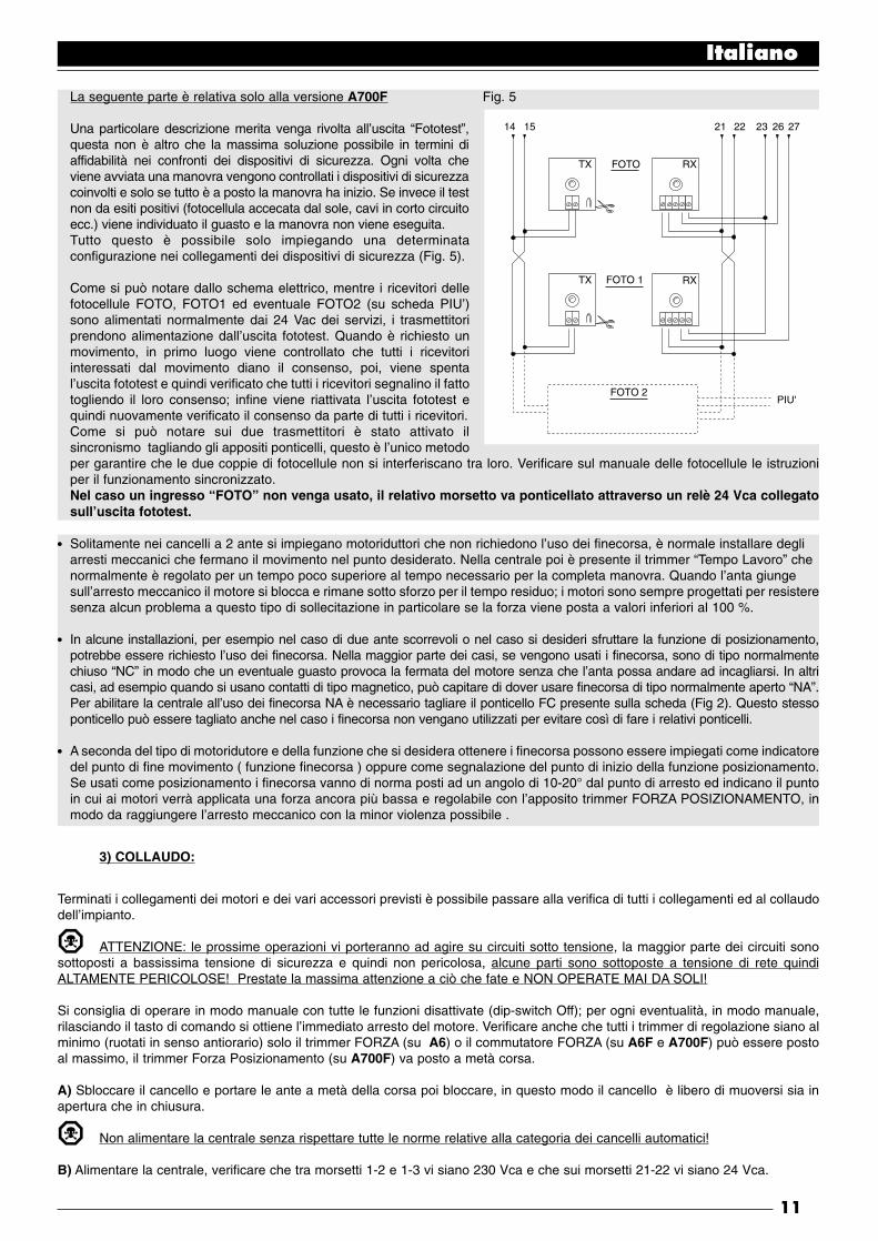
La seguente parte è relativa solo alla versione A700F Fig. 5
Una particolare descrizione merita venga rivolta all’uscita “Fototest”,questa non è altro che la massima soluzione possibile in termini diaffidabilità nei confronti dei dispositivi di sicurezza. Ogni volta cheviene avviata una manovra vengono controllati i dispositivi di sicurezzacoinvolti e solo se tutto è a posto la manovra ha inizio. Se invece il testnon da esiti positivi (fotocellula accecata dal sole, cavi in corto circuitoecc.) viene individuato il guasto e la manovra non viene eseguita.Tutto questo è possibile solo impiegando una determinataconfigurazione nei collegamenti dei dispositivi di sicurezza (Fig. 5).
Come si può notare dallo schema elettrico, mentre i ricevitori dellefotocellule FOTO, FOTO1 ed eventuale FOTO2 (su scheda PIU’)sono alimentati normalmente dai 24 Vac dei servizi, i trasmettitoriprendono alimentazione dall’uscita fototest. Quando è richiesto unmovimento, in primo luogo viene controllato che tutti i ricevitoriinteressati dal movimento diano il consenso, poi, viene spental’uscita fototest e quindi verificato che tutti i ricevitori segnalino il fattotogliendo il loro consenso; infine viene riattivata l’uscita fototest equindi nuovamente verificato il consenso da parte di tutti i ricevitori.Come si può notare sui due trasmettitori è stato attivato ilsincronismo tagliando gli appositi ponticelli, questo è l’unico metodoper garantire che le due coppie di fotocellule non si interferiscano tra loro. Verificare sul manuale delle fotocellule le istruzioniper il funzionamento sincronizzato.Nel caso un ingresso “FOTO” non venga usato, il relativo morsetto va ponticellato attraverso un relè 24 Vca collegatosull’uscita fototest.
Solitamente nei cancelli a 2 ante si impiegano motoriduttori che non richiedono l’uso dei finecorsa, è normale installare degli arresti meccanici che fermano il movimento nel punto desiderato. Nella centrale poi è presente il trimmer “Tempo Lavoro” che normalmente è regolato per un tempo poco superiore al tempo necessario per la completa manovra. Quando l’anta giunge sull’arresto meccanico il motore si blocca e rimane sotto sforzo per il tempo residuo; i motori sono sempre progettati per resisteresenza alcun problema a questo tipo di sollecitazione in particolare se la forza viene posta a valori inferiori al 100 %.
In alcune installazioni, per esempio nel caso di due ante scorrevoli o nel caso si desideri sfruttare la funzione di posizionamento,potrebbe essere richiesto l’uso dei finecorsa. Nella maggior parte dei casi, se vengono usati i finecorsa, sono di tipo normalmentechiuso “NC” in modo che un eventuale guasto provoca la fermata del motore senza che l’anta possa andare ad incagliarsi. In altricasi, ad esempio quando si usano contatti di tipo magnetico, può capitare di dover usare finecorsa di tipo normalmente aperto “NA”.Per abilitare la centrale all’uso dei finecorsa NA è necessario tagliare il ponticello FC presente sulla scheda (Fig 2). Questo stessoponticello può essere tagliato anche nel caso i finecorsa non vengano utilizzati per evitare così di fare i relativi ponticelli.
A seconda del tipo di motoridutore e della funzione che si desidera ottenere i finecorsa possono essere impiegati come indicatoredel punto di fine movimento ( funzione finecorsa ) oppure come segnalazione del punto di inizio della funzione posizionamento.Se usati come posizionamento i finecorsa vanno di norma posti ad un angolo di 10-20° dal punto di arresto ed indicano il puntoin cui ai motori verrà applicata una forza ancora più bassa e regolabile con l’apposito trimmer FORZA POSIZIONAMENTO, inmodo da raggiungere l’arresto meccanico con la minor violenza possibile .
3) COLLAUDO:
Terminati i collegamenti dei motori e dei vari accessori previsti è possibile passare alla verifica di tutti i collegamenti ed al collaudodell’impianto.
ATTENZIONE: le prossime operazioni vi porteranno ad agire su circuiti sotto tensione, la maggior parte dei circuiti sonosottoposti a bassissima tensione di sicurezza e quindi non pericolosa, alcune parti sono sottoposte a tensione di rete quindiALTAMENTE PERICOLOSE! Prestate la massima attenzione a ciò che fate e NON OPERATE MAI DA SOLI!
Si consiglia di operare in modo manuale con tutte le funzioni disattivate (dip-switch Off); per ogni eventualità, in modo manuale,rilasciando il tasto di comando si ottiene l’immediato arresto del motore. Verificare anche che tutti i trimmer di regolazione siano alminimo (ruotati in senso antiorario) solo il trimmer FORZA (su A6) o il commutatore FORZA (su A6F e A700F) può essere postoal massimo, il trimmer Forza Posizionamento (su A700F) va posto a metà corsa.
A) Sbloccare il cancello e portare le ante a metà della corsa poi bloccare, in questo modo il cancello è libero di muoversi sia inapertura che in chiusura.
Non alimentare la centrale senza rispettare tutte le norme relative alla categoria dei cancelli automatici!
B) Alimentare la centrale, verificare che tra morsetti 1-2 e 1-3 vi siano 230 Vca e che sui morsetti 21-22 vi siano 24 Vca.
Italiano
11
TX FOTO
FOTO 1
FOTO 2PIU'
RX
TX RX
14 21 22 23 26 2715
•
•
•

La seguente parte è relativa solo alla versione A700F
C) Verificare che sui morsetti 14-15 sia presente una tensione di 24 Vac per alimentazione trasmettitori delle fotocellule.
Non appena la centrale è alimentata le spie luminose (LED) che sono poste sugli ingressi attivi devono illuminarsi, inoltre dopopochi istanti il led “OK” dovrà iniziare a lampeggiare con cadenza regolare. Se tutto questo non avviene, togliere immediatamentealimentazione e controllare con maggior attenzione i collegamenti.
Il led “OK” posizionato al centro della scheda, ha il compito di segnalare lo stato della logica interna: un lampeggio regolare edalla cadenza di 1 secondo indica che il microprocessore interno è attivo ed è in attesa di comandi. Quando invece lo stessomicroprocessore riconosce una variazione dello stato di un ingresso (sia ingresso di comando che dip_switch delle funzioni)genera un doppio lampeggio veloce, questo anche se la variazione non provoca effetti immediati. Un lampeggio molto veloce per3 secondi indica che la centrale è appena stata alimentata e sta eseguendo un test delle parti interne, infine un lampeggioirregolare e non costante indica che il test non è andato a buon fine e quindi c’è un guasto.
D) Ora verificare che i led relativi agli ingressi con contatti tipo NC siano accesi (tutte le sicurezze attive) e che i ledrelativi ad ingressi tipo NA siano spenti (nessun comando presente), se questo non avviene controllare i collegamenti el’efficienza dei vari dispositivi
E) Verificare il corretto funzionamento di tutti i dispositivi di sicurezza presenti nell’impianto (arresto di emergenza,fotocellule, coste pneumatiche ecc.), ogni volta che intervengono, il relativi led ALT, FOTO o FOTO1 devono spegnersi.
Questa è una verifica fra le più importanti e deve essere eseguita con la massima attenzione, dal corretto funzionamento deidispositivi di sicurezza dipende tutta la sicurezza “attiva” della macchina cancello. Se il lampeggiante è un ottimo strumento persegnalare lo stato di pericolo ed i limitatori di coppia sono un valido ausilio per limitare i danni, solo una corretta installazione deidispositivi di sicurezza permette di bloccare l’automatismo prima che possa provocare danni.
La seguente parte è relativa solo alla versione A700F
F) Se vengono utilizzati gli ingressi finecorsa bisogna verificare l’esattezza dei collegamenti. Muovere le ante una alla volta everificare che una volta raggiunto il punto desiderato il relativo finecorsa intervenga spegnendo il corrispondente led sulla centrale(o accendendolo se sono montati dei finecorsa NA).
Ora bisognerà verificare se il movimento avviene nella direzione corretta cioè controllare la corrispondenza tra il movimentoprevisto dalla centrale e quello effettivo delle ante. Questa verifica è fondamentale, se la direzione è sbagliata in alcuni casi (adesempio in modo semiautomatico) il cancello potrebbe in apparenza funzionare regolarmente infatti il ciclo APRE è simile al cicloCHIUDE con la fondamentale differenza che i dispositivi di sicurezza verranno ignorati nella manovra di chiude, che normalmenteè la più pericolosa, ed interverranno in apertura provocando una richiusura addosso all’ostacolo con effetti disastrosi!
G) Per verificare se il senso di rotazione è esatto basta dare un breve impulso sull’ingresso Passo-Passo; la prima manovra chela centrale esegue dopo che è stata alimentata è sempre APRE, quindi è sufficiente verificare se il cancello si muove nel sensodell’apertura; infine nel caso il movimento sia avvenuto i senso errato occorre:
1 - Spegnere alimentazione2 - Scambiare i collegamenti “APRE” e “CHIUDE” del motore o dei motori che ruotavano in senso contrario.
Eseguito quanto descritto conviene riprovare se il senso di rotazione è corretto ripetendo l’operazione del punto “G”.
H) Verificati tutti i collegamenti ed eseguita la verifica del senso di rotazione dei motori è possibile provare un movimento completodegli attuatori, si consiglia di operare sempre in modo manuale con tutte le funzioni disattivate. Se si usa come comandol’ingresso Passo Passo il primo movimento (dopo l’accensione) dovrà essere in apertura. Agendo sugli ingressi di comandomovimentare il cancello fino al punto di apertura, se tutto si è svolto regolarmente è possibile passare al movimento in senso dichiusura e muovere il cancello fino al relativo punto di arresto.Conviene eseguire diverse manovre apre-chiude al fine di valutare eventuali difetti nella struttura meccanica dell’automazione edi rilevare la presenza di particolari punti di attrito.
I) Passare ora a provare l’intervento dei dispositivi di sicurezza, FOTO e FOTO1 nella manovra di apertura non hanno alcuneffetto, in chiusura provocano la fermata del movimento. Se presente la scheda PIU’ provare anche il funzionamento dell’ingressoFOTO 2, in chiusura non ha alcun effetto, in apertura provoca la fermata del movimento. I dispositivi collegati nell’ingresso ALTagiscono sia in apertura che in chiusura provocando sempre la fermata del movimento.
Italiano
12
•
•
•

3.1) REGOLAZIONI :
✓ Se il cancello è composto da 2 ante che sipossono incagliare se in apertura partonocontemporaneamente o se in chiusura una sisovrappone all’altra, allora è necessariointervenire sulle regolazioni dei trimmer TempoRitardo Apertura “TRA” o Tempo RitardoChiusura “TRC”. Questi trimmer possonoessere regolati a piacere anche se di normaTRA va regolato per lo stretto necessario a chel’anta mossa dal 2° motore sia già fuori zonad’ingombro quando parte il 1° motore.Il trimmer TRC deve essere regolato in modo che in chiusura l’anta del 2° motore giunga sempre quando il 1° motore ha giàterminato la manovra di chiusura.
Il Tempo Ritardo Chiusura può essere impiegato per realizzare il franco di sicurezza in chiusura di 50 cm previsto dal punto5.4.2.3. delle norme UNI 8612 ediz. 89.
✓ A questo punto selezionare il modo di funzionamento “Semiautomatico” spostando in On il dip-switch N°1 quindi regolare il trimmerTempo Lavoro circa a metà corsa. Con queste regolazioni provare un intero ciclo di apertura e poi uno di chiusura, eventualmenteintervenire sulla regolazione del trimmer Tempo Lavoro in modo tale che sia sufficiente ad eseguire tutta la manovra e rimanga ancoraun margine di tempo di 2 o 3 secondi. Nel caso anche ponendo al massimo il trimmer non si ottenga un tempo sufficiente e possibiletagliare il ponticello TLM posto sullo stampato vicino al trimmer ed ottenere così un tempo lavoro maggiorato.
Le normative UNI 8612 ediz.89 al fine di prevenire pericoli di schiacciamento prevedono al punto 6.1.5. tra le misurepossibili l’utilizzo di limitatori di coppia che possono essere regolati in modo che la spinta massima del cancello misurata sullospigolo dell’anta non superi i 150 N (~ 15 Kg). In verità la norma aggiunge la condizione che l’energia cinetica dell’anta sia inferiorea 10 Joule (10 N/m) ma non chiarisce quali metodi usare in alternativa; in ogni caso è una soluzione ottima e da applicare sempre!
✓ In alcuni tipi di attuatori, ad esempio il tipo oleodinamico, la regolazione della forza è prevista direttamente sul gruppo attuatore,consultare il relativo manuale di istruzioni per chiarimenti sulla regolazione, quindi lasciare la regolazione di forza interna allacentrale impostata per il massimo.Per tutti quei tipi di attuatori che non contengono un dispositivo di regolazione di forza è invece possibile sfruttare il sistema diregolazione di forza interno alla centrale: in base alla versione della centrale impiegata seguire le relative istruzioni.
La seguente parte è relativa solo alla versione A6
Sulla centrale è presente un trimmer FORZA che normalmente è posto per la massima forza, con un cacciavite ruotare il trimmerin senso antiorario fino a ridurre la forza del motore al valore previsto dalle normative.
La seguente parte è relativa solo alle versioni A6F e A700F
Sulla centrale è presente un autotrasformatore di adeguata potenza con delle prese intermedie sull’avvolgimento primarioselezionabili attraverso apposito commutatore FORZA, spostare il commutatore sulla posizione più adatta al fine di ridurre la forzadel motore al valore previsto dalle normative.
Qualunque sia il sistema di regolazione della forza per la fase iniziale del movimento e per una durata di 1,5 Sec viene data ilmassimo della forza, solo dopo questo tempo definito di “Spunto” viene inserita la forza prevista.
✓ Se viene selezionato il modo di funzionamento in automatico (dip-switch N° 2 On) al termine della manovra di apertura vieneeseguita una “pausa” al termine della quale viene lanciata automaticamente una manovra di chiusura. Questo tempo nel quale ilcancello rimane aperto è regolabile dall’apposito trimmer TEMPO PAUSA che può essere impostato per il tempo preferito senzaalcuna limitazione di sorta.Una chiusura automatica e quindi la relativa pausa viene attivata anche nel movimento in semiautomatico quando, in chiusura,l’intervento di un dispositivo di sicurezza provoca una inversione del movimento in apertura .
✓ Solo ora, al termine di tutte le regolazioni consigliamo di inserire l’eventuale ricevitore radio ricordando che i comandi da essoprovenienti vengono inviati all’ingresso PASSO-PASSO.
Italiano
13
TLM = Tempo Lavoro Maggiorato
TL = Tempo LavoroTP = Tempo PausaTRA = Tempo Ritardo AperturaTRC = Tempo Ritardo Chiusura
F = ForzaFP = Forza Posizionamento
TLM
TL
F FP
TP TRA TRC

3.2) MODI DI FUNZIONAMENTO:
Nota: alcune delle parti descritte a seguito sono relative solo alla versione A700F
Nel funzionamento in modo manuale, l’ingresso APRE consente il movimento in apertura, l’ingresso CHIUDE consente ilmovimento in chiusura. il PASSO P. consente il movimento alternativamente in apertura e in chiusura; non appena cessa ilcomando in ingresso il movimento si arresta. In apertura il movimento si arresta quando intervengono i finecorsa oppure se mancail consenso dalla FOTO2 (su scheda PIU’); in chiusura invece il movimento si arresta anche se manca il consenso di FOTO eFOTO1. Sia in apertura che in chiusura un intervento su ALT provoca sempre un immediato arresto del movimento. Una volta cheun movimento si è arrestato è necessario far cessare il comando in ingresso prima che un nuovo comando possa far iniziare unnuovo movimento.
Nel funzionamento in uno dei modi automatici (semiautomatico, automatico o chiude sempre) un impulso di comando sull’ingressoAPRE provoca il movimento in apertura, se il comando permane una volta raggiunta l’apertura il movimentorimane “congelato” in una pausa infinita; solo quando cessa il comando il cancello si potrà essere richiuso. Un impulso su PASSOPASSO provoca alternativamente apertura o chiusura. Un secondo impulso sul PASSO P. o sullo stesso ingresso che ha iniziatoil movimento provoca uno Stop.Sia in apertura che in chiusura un intervento su ALT provoca un immediato arresto del movimento.
Se in un ingresso di comando invece di un impulso viene mantenuto un segnale continuo si provoca uno stato di “prevalenza”in cui gli altri ingressi di comando rimangono disabilitati (utile per collegare un orologio o un selettore Notte-Giorno).
Nel caso fosse selezionato il modo di funzionamento automatico, dopo una manovra di apertura, viene eseguita una pausa altermine viene eseguita una chiusura. Se durante la pausa vi fosse un intervento di FOTO o FOTO1, il temporizzatore verràripristinato con un nuovo tempo pausa; se invece durante la pausa si interviene su ALT la funzione di richiusura viene cancellatae si passa in uno stato di STOP.
In apertura gli interventi di FOTO o FOTO1 non hanno alcun effetto mentre la FOTO2 (su scheda PIU’) provoca l’inversione delmoto; in chiusura l’intervento di FOTO o FOTO1 provoca una inversione del moto poi una pausa quindi una richiusura.
4) PROGRAMMAZIONE:
La centrale dispone di una serie di microinterrutori che permettono di attivare varie funzioni al fine di rendere l’impianto più adattoalle esigenze dell’utilizzatore e più sicuro nelle varie condizioni d’uso. Tutte le funzioni sono attivate ponendo il relativo dip-switchin posizione “On” mentre non sono inserite con il corrispondente dip-switch in “Off”; alcune funzioni non hanno una immediataefficacia ed hanno senso solo in determinate condizioni, ad esempio la funzione N° 12 “Lampeggiante anche in pausa” è attivasolo con la chiusura automatica e se la manovra non viene interrotta con un comando di ALT.
ATTENZIONE alcune delle funzioni programmabili solo legati ad aspetti della sicurezza, valutare con molta attenzione glieffetti di una funzione e verificare quale sia la funzione che dia la maggior sicurezza possibile.Nella manutenzione di un impianto prima di modificare una funzione programmabile valutare il motivo per cui nella fase diinstallazione erano state fatte determinate scelte, quindi verificare se con la nuova programmazione la sicurezza ne risente.
4.1) FUNZIONI PROGRAMMABILI:
Il dip-switch FUNZIONI permette di selezionare i vari modi di funzionamento e di inserire le funzioni desiderate secondo laseguente tabella:
Switch 1-2: Off Off = Movimento “Manuale” cioè Uomo Presente
On Off = Movimento “Semiautomatico”
Off On = Movimento “Automatico” cioè Chiusura Automatica
On On = Movimento “Automatico + Chiude Sempre”
Switch 3 On = Funzionamento Condominiale < Non disponibile in modo Manuale>
Switch 4 On = Prelampeggio
Switch 5 On = Richiudi subito dopo Foto < solo in modo Automatico >
Switch 6 On = Foto1 anche in apertura
Switch 7 On = Partenza graduale
Switch 8 On = Fermata graduale
Switch 9 On = Colpo d’ariete
Switch 10 On = Luce di cortesia su lampeggiante
Italiano
14

Nella versione A700F è presente un secondo gruppo di dip-switch con altre funzioni:
Switch 11 On = Funzione posizionamento < solo con l’utilizzo dei finecorsa >
Switch 12 On = Lampeggiante anche in Pausa < solo in modo Automatico >
Switch 13 On = Mantenimento pressione
Switch 14 On = Spia C.A. con lampeggio proporzionale
Switch 15 On = Attivazione Fototest
Switch 16 On = Foto e Foto1 anche in apertura
Switch 17 On = Foto e Foto1 ad inizio manovra di apertura
Switch 18 On = Salta STOP in apre
Switch 19 On = Salta STOP in chiude
Switch 20 On = CHIUDE diventa APRE PEDONALE
Ricordiamo che le funzioni che sono possibili solo in determinati casi sono segnalate con le note tra i caratteri “<>” dopo ladescrizione della funzione.
Naturalmente ogni dip-switch posto in “Off” non attiva la funzione descritta.
4.2) DESCRIZIONE DELLE FUNZIONI:
Riportiamo ora una breve descrizione delle funzioni che si possono inserire portando in “On” il relativo dip-switch
Switch 1-2: Off Off = Movimento “Manuale” (Uomo Presente)On Off = Movimento “Semiautomatico”Off On = Movimento “Automatico” (Chiusura Automatica)On On = Movimento “Automatico + Chiude Sempre”
Nel funzionamento “Manuale” il movimento viene eseguito solo fino alla presenza del comando (tasto premuto).In “Semiautomatico” basta un impulso di comando e viene eseguito tutto il movimento fino al raggiungimento dell’arrestomeccanico o fino all’intervento del finecorsa. Nel funzionamento in modo “Automatico” dopo una apertura viene eseguita unapausa e quindi una chiusura.La funzione “Chiude Sempre” interviene dopo una mancanza momentanea di alimentazione; se viene rilevato il cancelloaperto si avvia automaticamente una manovra di chiusura preceduta da 5 secondi di prelampeggio.
Switch 3: On = Funzionamento Condominiale (non disponibile in modo Manuale)
Nel funzionamento condominiale, una volta avviato un movimento in apertura la manovra non puó piú essere interrotta da altriimpulsi di comando su PASSO PASSO o APRE fino alla fine del movimento in apertura.Nel movimento in chiusura un nuovo impulso di comando provoca l’arresto e l’inversione del movimento in apertura.
Switch 4: On = Prelampeggio
All’impulso di comando viene prima attivato il lampeggiante poi dopo 5 secondi (2 Sec. se in manuale) inizia il movimento.
Switch 5: On = Richiudi subito dopo Foto (solo se in modo Automatico)
Questa funzione permette di tenere il cancello aperto solo per il tempo necessario al transito, infatti dopo l’intervento di FOTO oFOTO1 la chiusura avverrà sempre con una pausa di 5 secondi indipendentemente dal Tempo Pausa regolato.
Switch 6: On = Foto1 anche in apertura
Questa funzione è l’unica che diversifica il funzionamento tra le fotocellule FOTO e FOTO1. Normalmente le sicurezze FOTO eFOTO1 intervengono solo nella manovra di chiusura mentre in apertura non hanno alcun effetto.Se il dip-switch N° 6 viene posto “On” FOTO continua ad intervenire solo in chiusura ma FOTO1 interviene anche in aperturaprovocando una interruzione del movimento. In semiautomatico od automatico la ripresa del moto avverrà quando FOTO1 verrànuovamente disimpegnata.Questo tipo di funzionamento ritorna utile per arrestare il moto del cancello in apertura, quando, per esempio un veicolo si avvicinaal cancello dal lato interno e quindi nella direzione del movimento, senza nello stesso tempo fermare il movimento quando ilveicolo si avvicina dal lato esterno.
Switch 7: On = Partenza graduale
L’inizio del movimento viene eseguito in modo graduale inviando una forza sempre maggiore al motore formando una rampa chedura di circa 1 Sec, questo garantisce che la partenza avvenga senza scossoni. (Funzione sconsigliata su motoriduttori METRO).
Italiano
15
•
•

Switch 8: On = Fermata graduale
Quando il movimento termina viene eseguita una fermata in modo graduale inviando una forza sempre minore al motore con undecremento che dura circa 1 Sec, questo garantisce che la fermata avvenga senza scossoni.Per ovvi motivi di sicurezza la fermata graduale non avviene, e viene sostituita da una fermata normale, quando interviene ALT,FOTO e FOTO1o FOTO2 (su scheda PIU’) oppure uno dei finecorsa.
Switch 9: On = Colpo d’ariete
Quando si impiegano attuatori reversibili, quindi il cancello non rimane chiuso con la sola spinta dei motori, diventa indispensabileinstallare una elettroserratura (vedere le istruzioni degli attuatori per le modalità d’uso).Sull’elettroserratura si potrebbe così trovare applicata quella naturale spinta che tende a portare le ante in posizione leggermenteaperta, talvolta questa spinta è così elevata da mantenere bloccato il meccanismo di scatto dell’elettroserratura. Con la funzione colpo d’ariete inserita, prima di iniziare una manovra di apertura viene attivato un breve ciclo di chiude, checomunque non crea alcun effetto di movimento visto che le ante sono già sull’arresto meccanico di chiusura. In questo modoquando l’elettroserratura viene attivata si troverà scarica da qualsiasi forza e quindi libera di scattare.
Switch 10: On = Luce di cortesia su lampeggiante
In determinati casi può essere richiesto una illuminazione sulla zona di movimento del cancello e spesso si richiede chel’illuminazione si spenga automaticamente poco dopo che il cancello ha concluso la manovra. Questa funzione vienecomunemente definita “Luce di cortesia”. Collegando degli appropriati corpi illuminanti sulla stessa uscita del lampeggiate (peruna potenza massima complessiva di 100 W) ed attivando questa funzione si otterrà che durante tutto il movimento e per altri 60Sec. l’uscita rimarrà attiva permettendo l’illuminazione della zona.
Solo nella versione A700F è presente un secondo gruppo di dip-switch con altre funzioni:
Switch 11 On = Funzione posizionamento (solo con l’utilizzo dei finecorsa)
I finecorsa possono essere impiegati, invece che come segnalazione dei limiti del movimento, come indicazione del punto in cuiscatta il posizionamento. Di norma quando si usa la funzione posizionamento i finecorsa vengono posti ad un angolo di 10-20°prima dell’arresto meccanico. In questo modo quando nel movimento dell’anta si raggiunge il finecorsa al motore verrà inviata unaforza minore, regolabile con l’apposito trimmer “Forza Posizionamento”, per un tempo di altri 3 Sec. in modo che l’anta raggiungal’arresto meccanico con la minor violenza possibile.
Switch 12 On = Lampeggiante anche in Pausa
Normalmente il lampeggiante viene attivato solo durante il movimento in apertura o chiusura, questa funzione prevede che illampeggiante rimanga attivo anche durante la Pausa allo scopo di segnalare lo stato di “prossima chiusura”.
Switch 13 On = Mantenimento pressione
Negli attuatori oleodinamici la spinta per mantenere chiuso il cancello è sviluppata in un circuito idraulico che rimane sempre sottopressione. Quando il tempo e l’usura riducono la tenuta del circuito idraulico può capitare che dopo qualche ora la pressioneinterna decada con conseguente rischio di leggera apertura delle ante del cancello.Se si inserisce la funzione Mantenimento Pressione, dopo 4 ore, poi ogni 4 ore che il cancello è chiuso viene attivata una brevemanovra di chiude con il solo scopo di ricaricare la pressione del circuito idraulico.
NOTA: Le funzioni “Colpo d’ariete” e “Mantenimento pressione” hanno senso e vengono eseguite solo se il cancello è chiuso. Lalogica interna considera cancello chiuso se c’è il relativo finecorsa FCC intervenuto o, nel caso i finecorsa non siano usati, dalfatto che la precedente manovra di chiusura è terminata regolarmente per fine del tempo lavoro.
Switch 14 On = Spia C.A. con lampeggio proporzionale
Normalmente la Spia Cancello Aperto indica lo stato del cancello secondo i seguenti stati:
Spenta : Cancello completamente chiusoAccesa : Cancello anche solo parzialmente apertoLampeggio lento : Cancello in fase di aperturaLampeggio veloce : Cancello in fase di chiusura
Il lampeggio della spia durante il movimento può essere reso proporzionale, da lento, progressivamente a veloce e viceversa in modo di avere un’indicazione dello stato di apertura o chiusura.
Switch 15 On = Attivazione Fototest
Permette di avviare una fase di test sulle fotocellule prima di iniziare ogni movimento, in questo modo eliminando ogni possibilità
Italiano
16

di malfunzionamento si aumenta la sicurezza dell’impianto. Per sfruttare la funzione Fototest è necessario che i trasmettitori dellefotocellule siano collegati all’apposita uscita (vedere: Note dei collegamenti).
Switch 16 On = Foto e Foto1 anche in apertura
Normalmente le sicurezze FOTO e FOTO1 intervengono solo nella manovra di chiusura, se il dip-switch N° 16 viene attivatol’intervento dei dispositivi di sicurezza provocano una interruzione del movimento anche in apertura, se in Semiautomatico odAutomatico si avrà la ripresa nuovamente del moto in apertura subito dopo il disimpegno.
Switch 17 On = Foto e Foto1 ad inizio manovra di apertura
Solitamente i dispositivi di sicurezza FOTO e FOTO1 non sono attivi nella manovra di apre ma solo nella manovra di chiude perchèla più pericolosa. In alcune nazioni vi sono delle normative che impongono il controllo dei dispositivi di sicurezza almeno all’inizioanche della manovra di apre. Se è necessario rispettare queste norme o si desidera aumentare il livello di sicurezza e possibileattivare la funzione e quindi prima di iniziare il movimento, verificare il consenso dalle sicurezze FOTO e FOTO1 e solo dopoiniziare il movimento.
Switch 18 On = Salta STOP in apre
Il ciclo del Passo Passo è normalmente: APRE-STOP-CHIUDE-STOP, con questa funzione inserita il ciclo Passo Passodiventa: APRE-CHIUDE-STOP-APRE, mentre l’ingresso Apre perde la possibilità di fare STOP
Switch 19 On = Salta STOP in chiude
E’ come la funzione precedente ma relativa al ciclo chiude, quindi il ciclo Passo Passo diventa: APRE-STOP-CHIUDE -APRE ,mentre l’ingresso Chiude perde la possibilità di fare STOP
NOTA: Ponendo On i dip-switch 18 e 19 il ciclo passo passo diventa APRE-CHIUDE-APRE perdendo definitivamente la possibilitàdi fare STOP.
Switch 20 On = CHIUDE diventa APRE PEDONALE
Può capitare che non sia necessario aprire completamente il cancello ad esempio quando deve transitare un pedone in questocaso diventa utile la funzione di APRE PEDONALE che permette di aprire solo l’anta collegata al 2° motore lasciando l’altra chiusa.Questo tipo di apertura viene attivata dall’ingresso CHIUDE che perde la sua funzione originale per diventare come l’ingressoPasso-Passo ma per l’apertura di una sola anta. E’ da precisare che il ciclo di apre pedonale si attiva solo partendo da cancellochiuso se invece il cancello è in movimento o comunque aperto l’impulso di ingresso non ha alcun effetto.
ACCESSORIO : SCHEDA ESPANSIONI “ PIU’ “
La centrale elettronica dispone di tutte le principali funzioni richieste in una normale automazione, nella versione A700F è stataprevista la possibilità di aggiungere la scheda opzionale PIU’ che permette di aumentare le prestazione della centrale.
La seguente parte è relativa solo alla versione A700F
La scheda va innestata nell’apposito connettore sulla centrale, quindi sui morsetti della scheda sono disponibili :
• I seguenti ingressi:
Foto 2 = Dispositivo di sicurezza con intervento nella manovra di aperturaApre Parziale = Esegue una manovra di apertura con un tempo ridotto
• Le seguenti uscite:
Rosso = Luce rossa del semaforo \Verde = Luce verde del semaforo | AllarmiElettroserratura = Comando dell’elettroserratura (visto che la centrale dispone già di questa uscita la funzione è
stata modificata in “Ventosa” per collegare quei dispositivi di ritenuta magnetica che si usano in alternativa all’elettroserratura)
Luce di Cortesia = Comando di una lampada con funzione di luce di cortesia
Nota: Le uscite possono comandare solo carichi di piccola potenza (lampade spia, relè ecc.)
• e le seguenti regolazioni:
Tempo Parziale = Tempo per l’apertura parzialeTempo Cortesia = Tempo per la luce di cortesia
Le caratteristiche complete e la modalità d’uso della scheda sono riportate nel relativo manuale di istruzioni.
Italiano
17

CARATTERISTICHE TECNICHE DELLA CENTRALE:
Alimentazione : 230 Vac ± 20%, 50 HzPotenza massima attuatori : due motori da 1/2 Hp con condensatore massimo da 20 µFPotenza massima lampeggiante : 100 W a 230 Vac ( l’uscita presenta tensione fissa.)
Corrente Max servizi 24 Vac : 200 mACorrente Max uscita fototest : 100 mAPotenza massima spia CA : 2 W (24 Vac)Potenza massima elettroserratura : 25 W (12 Vac)Tempo lavoro : da 2,5 a 40 Sec. (da 30 a 80 Sec. con TLM)Tempo pausa : da 5 a 80 Sec.Tempo ritardo apertura TRA : 0 oppure da 2.5 a 12 Sec. (ritardo partenza 1° motore in apertura)Tempo ritardo chiusura TRC : 0 oppure da 2.5 a 12 Sec. (ritardo partenza 2° motore in chiusura)Regolazione forza : da 0 al 100% su versione A6; 30-45-60-80-100% su versione A6F e A700FTemperatura di esercizio : -20 ÷ 70 °C
Dimensioni : 280 x 220 x 110Peso : 2,7 Kg circaGrado di protezione : IP 55
Nice s.r.l. si riserva il diritto di apportare modifiche ai prodotti in qualsiasi momento senza preavviso.
Italiano
18
NOTE FINALI :
Il presente manuale è destinato solamente al personale tecnico qualificato per l’installazione.
• Nessuna informazione contenuta nel presente fascicolo può essere considerata interessante per l’utilizzatore finale!
• Nessuna impostazione o regolazione contenuta nel presente fascicolo può essere eseguita dall’utilizzatore finale!
✓ Terminato l’impianto , informare accuratamente anche in modo scritto l’utilizzatore finale sulla modalità d’uso del cancelloautomatico, sulla pericolosità residua, sulla modalità di sblocco manuale in caso di mancanza dell’energia elettrica.
✓ Informare il proprietario dell’impianto sulla necessità di una manutenzione accurata e costante in particolare sulla necessitàdi un controllo periodico dei dispositivi di sicurezza e dei limitatori di coppia.

This manual is for use only by technical personnel qualified to carry out the installation.No information given in this manual can be considered of any interest to the end user!
This handbook is enclosed with items A6, A6F and A700F and must not be used for different products!
IMPORTANT NOTICE:
The unit described in this handbook is designed to control one or two electromechanical actuators for the automation of doors orgates. Any other use is considered improper and consequently forbidden by current laws.
It is our duty to remind you that you are carrying out operations on machine systems classified in the “Gates and automatic doors”category and as such are considered particularly “hazardous”; it is your job to make them as “Safe” as is reasonably possible!
Only qualified, expert personnel may carry out installation and any servicing required, making the best possible job of itand in compliance with the following Italian laws, standards or European directives:
• UNI 8612 standard (Motorised gates and main doors: construction criteria and protection devices against accidents)
• DPR No. 46 of 5/03/1990 (Standards for the safety of electrical installations, authorised personnel)
• Decree Law No. 459/96 of 24/07/96 (EEC directive 89/392, Machine Directive)
• Decree Law No. 615/96 of 12/11/96 (EEC directive 89/336, Directive on Electromagnetic Compatibility)
• Decree Law No. 626/96 of 26/11/96 (EEC directive 93/68, Low Voltage Directive)
When designing and producing its products, Nice observes (as regards the equipment) all the above standards but it is ofparamount importance that the installer too (as regards the systems) continues the strict observance of the same standards.
Unqualified personnel or those who do not know the standards applicable to the “Automatic gates and doors” category:Must under no circumstances carry out installations and systems
Whoever carries out systems without observing all the applicable standards:Will be held responsible for any damages that the system may cause!
CONTENTS:
Quick guide Page 201 Introduction 221.1 Description 22 2 Installation instructions 232.1 Installation 232.2 Diagram of connections 242.3 Description of connections 252.4 Notes about connections 263 Test 273.1 Adjustments 293.2 Functioning modes 304 Programming 304.1 Programmable functions 304.2 Description of the functions 31
Optional : PIU’ expansions card 33Technical features of the unit 34
English
19
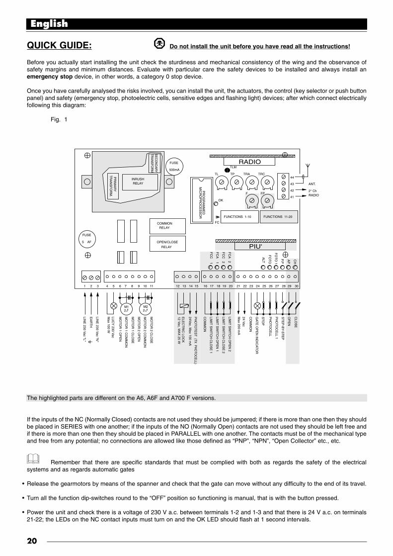
QUICK GUIDE: Do not install the unit before you have read all the instructions!
Before you actually start installing the unit check the sturdiness and mechanical consistency of the wing and the observance ofsafety margins and minimum distances. Evaluate with particular care the safety devices to be installed and always install anemergency stop device, in other words, a category 0 stop device.
Once you have carefully analysed the risks involved, you can install the unit, the actuators, the control (key selector or push buttonpanel) and safety (emergency stop, photoelectric cells, sensitive edges and flashing light) devices; after which connect electricallyfollowing this diagram:
Fig. 1
The highlighted parts are different on the A6, A6F and A700 F versions.
If the inputs of the NC (Normally Closed) contacts are not used they should be jumpered; if there is more than one then they shouldbe placed in SERIES with one another; if the inputs of the NO (Normally Open) contacts are not used they should be left free andif there is more than one then they should be placed in PARALLEL with one another. The contacts must be of the mechanical typeand free from any potential; no connections are allowed like those defined as “PNP”, “NPN”, “Open Collector” etc., etc.
Remember that there are specific standards that must be complied with both as regards the safety of the electricalsystems and as regards automatic gates
Release the gearmotors by means of the spanner and check that the gate can move without any difficulty to the end of its travel.
Turn all the function dip-switches round to the “OFF” position so functioning is manual, that is with the button pressed.
Power the unit and check there is a voltage of 230 V a.c. between terminals 1-2 and 1-3 and that there is 24 V a.c. on terminals21-22; the LEDs on the NC contact inputs must turn on and the OK LED should flash at 1 second intervals.
English
20
CLO
SE
OP
EN
ST
EP
-BY-S
TE
P
PH
OT
OC
ELL 1
P
HO
TO
CE
LL
ST
OP
GA
TE
OP
EN
IND
ICA
TO
R
CO
MM
ON
24 Vac
Max 200 m
A
LIMIT
SW
ITC
H O
PE
N 2
LIMIT
SW
ITC
H C
LOS
E 2
LIMIT
SW
ITC
H O
PE
N 1
LIMIT
SW
ITC
H C
LOS
E 1
CO
MM
ON
PH
OT
OT
ES
T (TX
PH
OTO
CE
LL)
24Vac, M
ax 100 mA
ELE
CT
RIC
LOC
K
MO
TO
R 2 C
LOS
E
MO
TO
R 2 C
OM
MO
N
MO
TO
R 2 O
PE
N
MO
TO
R 1 C
LOS
E
MO
TO
R 1 C
OM
MO
N
MO
TO
R 1 O
PE
N
LUC
Y 230 V
acM
ax 100 W
LINE
230 Vac "N
"
EA
RT
H I
LINE
230 Vac "L"
12 Vac, M
AX
25 W
PR
OG
RA
MM
ED
MIC
RO
PR
OC
ES
SO
R
CH
AP
P.P
FO
TO
1
FO
TO
ALT
FC
A 2
FC
C 2
FC
A 1
FC
C 1
SE
CO
ND
AR
YTR
AN
SFO
RM
.
PR
IMA
RY
TR
AN
SF
OR
M.
FUSETLM
TL
OK
FC
F FP
TP44
43
42
41
TRA
ANT.
RADIO
FUNCTIONS 1-10 FUNCTIONS 11-20
2° Ch
TRC500mA
FUSE
M12 2
M2
5 AF
1 2 3 4 5 6 7 8 9 10 11 12 13 14 15 16 17 18 19 20 21 22 23 24 25 26 27 28 29 30
COMMON RELAY
INRUSHRELAY
OPEN/CLOSE
RELAY
RADIO
PIU'
•
•
•

If the limits switches are installed on the A700F version, check correspondence of the four LEDs: FCA1, FCA2 FCC1 and FCC2;when the gates are closed only the two FCC LEDs should turn off and when they are open only the two FCA LEDs should turn off.
With the gates half way open, so they can move freely in either direction, give a brief command pulse on the OPEN input or onthe STEP-BY-STEP if it is the first manoeuvre after the unit has been powered. Now, if the gate does not move in the openingdirection, turn the electrical power off and reverse motor connections on terminals 6-8 or 9-11; now see if rotation direction iscorrect.
Try and carry out a complete manoeuvre until the mechanical stop points are reached or when the limit switches trigger; then trya manoeuvre in the opposite direction.
The unit has a torque limiting device built into it, as prescribed by the UNI 8612 standard 89th edition, depending on the versions;adjust the FORCE with the relative trimmer or the commutator on the transformer so that the thrust on the outermost point of thegate does not exceed 150 N (about 15 Kg).
If you wish to select a semiautomatic or automatic movement you will have to adjust the WORKING TIME trimmer to have a marginof 2-3 seconds on the time needed for the movement.
Adjust the PAUSE TIME trimmer to your liking only if you have selected the automatic mode.
There are two trimmers on the control unit for adjusting the DELAY OPENING TIME and the DELAY CLOSING TIME. If required,adjust delay opening time so the gates do not bang into each other during movement and adjust delay closing time so the secondgate closes on the first.
Set the FUNCTIONS dip-switches as you want:
Switches 1-2 : Off Off = “Manual” movement (Man Present)On Off = “Semiautomatic” movementOff On = “Automatic” movement (Automatic Closing)On On = “Automatic+Always Closes” movement
Switch 3 : On = Condominium functioning mode < Not available in the Manual mode >Switch 4 : On = PreflashingSwitch 5 : On = Recloses immediately after Photocell < Only in the Automatic mode > Switch 6 : On = Photocell 1 also in OpeningSwitch 7 : On = Gradual start < Not recommended on METRO gear motor >Switch 8 : On = Gradual stopSwitch 9 : On = Water hammering Switch 10 : On = Courtesy light on flashing
There is a second set of dip-switches with other functions only on the A700F version:
Switch 11 On = Positioning function < only with the aid of the limit switch >Switch 12 On = Flashing also in Pause < Only in the Automatic mode >Switch 13 On = Pressure holdingSwitch 14 On = Gate Open Indicator with proportional flashingSwitch 15 On = Phototest operationSwitch 16 On = Photocell and Photocell 1 also in openingSwitch 17 On = Photocell and Photocell 1 at start of the opening manoeuvreSwitch 18 On = Misses STOP in opening Switch 19 On = Misses STOP in closingSwitch 20 On = CLOSE becomes PEDESTRIAN OPEN
Remember that some functions are only possible in certain cases; others can only be carried out after specific events; check thenotes between “<>” that follow a function description.
Now try all the different manoeuvre possibilities with the functions you have just installed; carefully evaluate the effectiveness ofthe safety devices and emergency stop.
Inform the end user, in detail, about how to use the automatic gate, about residual hazards, about how to use the manual unlockin the event of a power cut and about the need for a regular and accurate maintenance especially regarding a regular check ofthe safety and torque limiting devices.
English
21
•
•
•
•
•
•
•
•
•
•

1) INTRODUCTION:
The electronic unit is designed to control the movement of automatic gates and doors; it can be connected to electromechanicalactuators equipped with asynchronous single-phase motors running on 230 V a.c., for example the PLUTO PL 4000 or METROME 3000 models, made by Nice.
This instruction manual refers to several versions of the same unit; the difference of the various versions lies in a differentcompletion of the programmable functions and of the inputs available besides a different method used to control actuator force:
A6 : Base version, adjustment of the electronic force with phase step control A6F : Base version, adjustment of the electromechanical force with commutable autotransformerA700F : Complete version, adjustment of the electromechanical force with commutable autotransformer
“Manual”, “semiautomatic” or “automatic” operations are possible with this unit; during movement the consents of the safetydevices (STOP, PHOTOCELL, PHOTOCELL 1 inputs) are controlled; in the A700F version movement limits are verified by meansof the limit switch, while in the A6 version movement is timed.It has sophisticated, logical type functions going from “Movement memory” to “Close immediately after Photocell”, passing by
“Close always” and certain operating functions such as “Gradual start”, “Gradual stop”.In the A700F version, by plugging in the “PIU” model expansions cards, you can expand the functions even more by means ofother inputs and outputs.All the units are designed for connecting a wide range of Nice made radio receivers.
The most advanced techniques have been adopted in the project to guarantee maximum immunity to interference, greaterflexibility of use and the widest choice of programmable functions.
1.1) DESCRIPTION:
In view of this product’s peculiarities and the use of techniques that cannot be compared to other similar products, before you startinstalling the unit and wiring it, here is a brief description of the most important elements on the card.
Fig. 2
1: Power transformer (only A6)2: Plugs for external autotransformer (only A6F or A700F)3: 500 mA rapid fuse on 24 Vac power4: Plug for RADIO card5: Times adjustment trimmers6: Aerial terminal board and 2nd RADIO channel output7: Dip-switch to select functions8: Plug for the PIU’ card (only A700F)9: Indicator LEDs to signal state of the inputs10: Terminal board for inputs of safety devices and controls11: Terminal board for limit switch inputs (only A700F)12: Terminal board for electric lock and Phototest outputs(only A700F)13: Terminal board for flashing lamp and motor outputs14: 230 Vac power terminal board15: 5 A rapid fuse on 230 Vac power16: OK LED17: Force adjustment trimmer18: FC jumper for limit switch with NO contacts
The task of the OK LED (16) is to signal the correct functioning of the internal logic; it must flash at 1 second intervals and indicatesthat the internal microprocessor is working and waiting for commands. Whenever there is a variation in the state of the inputs (10-11) or of the function dip-switches (7), a double, quick flashing is generated even if the effects of the variation are not immediate.When the unit is powered, the luminous indicators (9) on the inputs turn on if that particular input is active and if there is a controlvoltage of 24 Vac. As a rule, the LEDs on the safety device inputs STOP, PHOTOCELL and PHOTOCELL 1 and those on the limitswitches are always on while those on the STEP-BY-STEP, OPEN and CLOSE are normally off.
English
22
CH
AP
P.P
FO
TO
1
FO
TO
ALT
FC
A 2
FC
C 2
FC
A 1
FC
C 1
FUSETLM
TL
OK
FC
F FP
TP44
43
42
41
TRA
FUNCTIONS 1-10 FUNCTIONS 11-20
TRC500mA
FUSE
5 AF
1 2 3 4 5 6 7 8 9 10 11 12 13 14 15 16 17 18 19 20 21 22 23 24 25 26 27 28 29 30
RADIO
PIU'
1 23 4 5
6
7
8
9
1012 111314
15
16
18
17

2) INSTALLATION INSTRUCTIONS:
Do not install the unit without first having read the instructions for the unit and actuators!
Before you actually start installation, check the sturdiness and mechanical consistency of the gate and the observance of safetymargins and minimum distances. Follow exactly all the indications given in the gearmotor instruction manuals.
Once you have carefully analysed the risks involved with the automation, evaluate with particular care, the safety devicesto be installed and always install an emergency stop device, in other words, a category 0 stop device.Remember there are specific standards to be strictly followed regarding the safety of electrical installations and automatic gates!
Besides these standards, that refer to electrical installations in general, machine systems and automatic doors and gates, hereare some of our own, specific notes for this unit that will make the whole system even more safe and reliable:
The power line leading to the unit must always be protected by a magnetothermic switch or by a couple of 5A fuses, a differentialswitch is recommended but not essential if there is already one before the system.
Power the unit using a 3 x 1.5 mm2 cable (phase + neutral + earth); should the distance between the unit and the earth connectionexceed 30 metres, an earth plate must be installed near the unit.
If the motors have no cable, use a 4 x 1.5 mm2 type (open + close + common + earth); the cable length must never be more than3 metres in length.
It is absolutely forbidden to connect cables in buried boxes even if they are completely watertight.
For the connections of the low voltage safety part (terminals 12...30) use wires with a minimum cross section of 0.25 mm2; for theelectric lock only, use a wire of at least 1 mm2. Use shielded wire if the length exceeds 30 metres, connecting the earth braid onlyon the unit side.
Always and only use cables (various wires insulated individually plus an additional general insulation) and never single wires evenif they are protected inside ducts.
Make sure you have all the necessary materials and that they are suitable for this use.
2.1) INSTALLATION:
Install the actuators following carefully all the instructions given in the relative instruction manuals that should be enclosed withthe motors. Should you find any clashes between the actuator instructions and this manual, do not install before all doubts havebeen cleared up by contacting the actuator supplier or our TECHNICAL OFFICE.
A correct choice in the installation of the unit is essential to guarantee an adequate level of safety and good protection againstatmospheric agents. Remember that the unit contains live parts and electronic components that are, in themselves, of aparticularly delicate nature.
The unit is supplied in a container which, if appropriately installed, will guarantee a protection level of IP55 (in compliance with CEI70-1 and IEC 529) which means it is suitable for outdoor installation too.However, several simple but important rules must be followed:
Install the unit on a permanent surface that is perfectly flat and adequately protected against knocks.
Secure the unit’s container with suitable means so that the bottom of it is at least 40 cm from the ground.For securing the container please refer to the instructions given at the end of this manual
Install cable or pipe leads only at the bottom of the unit; for no reason whatsoever must the side and top walls be perforated. Thecables must only enter the unit from the bottom!
If pipes are used that could fill with water or if they lead from a buried pit, it will be necessary to make the pipes pass through afirst junction box positioned at the same height as the unit and from this junction box, always from the bottom, into the unit’scontainers. This will prevent any evaporation of water inside the pipes from forming condensation inside the unit.
English
23
•
•
•
•
•
•
•
•
•

Once everything has been installed it ought to look something like this drawing:
Fig. 3
1: 230 V power line2: A6, A6F or A700F unit3: LUCY flashing lamp4: Couple of photoelectric cells(PHOTOCELL)
5: Electromechanical actuators6: Couple of photoelectric cells(PHOTOCELL 1)
NOTE: This diagram only shows a possible application of the unit and should be considered merely as an example. Onlyan in-depth analysis of the risks of the “Machine” gate and a proper evaluation of the end user requirements will be ableto establish how many and which elements must be installed.
2.2) DIAGRAM OF THE CONNECTIONS:
Once the unit, the actuators, the control (key selector or push button panel) and safety (emergency stop, photoelectric cells,sensitive edges and flashing light) elements have been installed, you can now do the wiring, following the instructions given below.
To safeguard the operator and avoid damaging the components while you are wiring, whether it is low voltage (230 V) orextra low voltage (24 V) or if you are plugging in the various cards:
The unit must, under no circumstances, be electrically powered.
We also wish to remind you that if the inputs of the NC (Normally Closed) contacts are not used they should be jumpered; if thereis more than one then they should be placed in SERIES with one another; if the inputs of the NO (Normally Open) contacts arenot used they should be left free and if there is more than one then they should be placed in PARALLEL with one another. Thecontacts must be of the mechanical type and free from any potential; no connections are allowed like those defined as “PNP”,“NPN”, “Open Collector” etc., etc.
Carry out the necessary connections, following the diagram in Fig. 4 and the following description of the connections.
Remember that there are specific standards that must be complied with both as regards the safety of the electricalsystems and as regards automatic gates
English
24
6
1
LINE 230 vac
2
3 4
5

Fig. 4
The highlighted part is only found on the A700F version.The highlighted part is found on the A6F and A700F versions.
Only qualified, expert personnel may carry out installation and subsequent maintenance, in compliance with the DPR N°46 dated 5/3/1990, in total observance of the UNI 8612 standards and following the best indications dictated by “expertworkmanship”. Whoever carries out these jobs is held responsible for any damage caused.
2.3) DESCRIPTION OF THE CONNECTIONS:
Here is a brief description of the possible connections of the unit to the outside:
1...3 : 230 Vac = 230 V a.c. 50 Hz
4-5 : Flashing light = Output for connection to the 230 V a.c. flashing light, maximum lamp power 100 W
6...8 : Motor 1 = 230 V a.c. output for connection to the 1st motor, maximum motor power 1/2 Hp
9...11 : Motor 2 = 230 V a.c. output for connection to the 2nd motor, maximum motor power 1/2 Hp
Note: Motors 1 and 2 only differ in the start delay; the 1st motor is connected to the opening delay time “TRA” while the2nd motor is connected to the closing delay time “TRC”. If the delays are unnecessary there is no difference between the motors.
English
25
CH
AP
P.P
FO
TO
1
FO
TO
ALT
FC
A 2
FC
C 2
FC
A 1
FC
C 1
FUSE
44
43
42
41
ANT.
RADIO
FUNCTIONS 1-10 FUNCTIONS 11-20
2° Ch
500mA
FUSE
M12 2
M2
5 AF
1 2 3 4 5 6 7 8 9 10 11 12 13 14 15 16 17 18 19 20 21 22 23 24 25 26 27 28 29 30
RADIO
PIU'
CLO
SE
OP
EN
ST
EP
-BY-S
TE
P
PH
OT
OC
ELL 1
P
HO
TO
CE
LL
ST
OP
GA
TE
OP
EN
IND
ICA
TO
R
CO
MM
ON
24 Vac
Max 200 m
A
LIMIT
SW
ITC
H O
PE
N 2
LIMIT
SW
ITC
H C
LOS
E 2
LIMIT
SW
ITC
H O
PE
N 1
LIMIT
SW
ITC
H C
LOS
E 1
CO
MM
ON
PH
OT
OT
ES
T (TX
PH
OTO
CE
LL)
24Vac, M
ax 100 mA
ELE
CT
RIC
LOC
K
MO
TO
R 2 C
LOS
E
MO
TO
R 2 C
OM
MO
N
MO
TO
R 2 O
PE
N
MO
TO
R 1 C
LOS
E
MO
TO
R 1 C
OM
MO
N
MO
TO
R 1 O
PE
N
LUC
Y 230 V
acM
ax 100 W
LINE
230 Vac "N
"
EA
RT
H
LINE
230 Vac "L"
12 Vac, M
AX
25 W
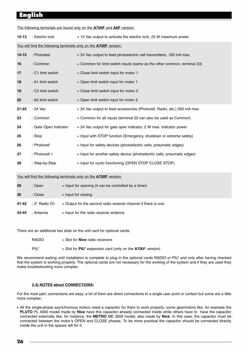
The following terminals are found only on the A700F and A6F version:
12-13 : Electric lock = 12 Vac output to activate the electric lock, 25 W maximum power
You will find the following terminals only on the A700F version:
14-15 : Phototest = 24 Vac output to feed photoelectric cell transmitters, 100 mA max.
16 : Common = Common for limit switch inputs (same as the other common, terminal 23)
17 : C1 limit switch = Close limit switch input for motor 1
18 : A1 limit switch = Open limit switch input for motor 1
19 : C2 limit switch = Close limit switch input for motor 2
20 : A2 limit switch = Open limit switch input for motor 2
21-22 : 24 Vac = 24 Vac output to feed accessories (Photocell, Radio, etc.) 200 mA max.
23 : Common = Common for all inputs (terminal 22 can also be used as Common)
24 : Gate Open Indicator = 24 Vac output for gate open indicator, 2 W max. indicator power
25 : Stop = Input with STOP function (Emergency, shutdown or extreme safety)
26 : Photocell = Input for safety devices (photoelectric cells, pneumatic edges)
27 : Photocell 1 = Input for another safety device (photoelectric cells, pneumatic edges)
28 : Step-by-Step = Input for cyclic functioning (OPEN STOP CLOSE STOP)
You will find the following terminals only on the A700F version:
29 : Open = Input for opening (it can be controlled by a timer)
30 : Close = Input for closing
41-42 : 2° Radio Ch = Output for the second radio receiver channel if there is one
43-44 : Antenna = Input for the radio receiver antenna
There are an additional two slots on the unit card for optional cards:
RADIO = Slot for Nice radio receivers
PIU’ = Slot for PIU’ expansion card (only on the A700F version)
We recommend waiting until installation is complete to plug in the optional cards RADIO or PIU’ and only after having checkedthat the system is working properly. The optional cards are not necessary for the working of the system and if they are used theymake troubleshooting more complex.
2.4) NOTES about CONNECTIONS:
For the most part, connections are easy; a lot of them are direct connections to a single user point or contact but some are a littlemore complex:
All the single-phase asynchronous motors need a capacitor for them to work properly; some gearmotors like, for example thePLUTO PL 4000 model made by Nice have this capacitor already connected inside while others have to have the capacitorconnected externally like, for instance, the METRO ME 3000 model, also made by Nice. In this case, the capacitor must beconnected between the motor’s OPEN and CLOSE phases. To be more practical the capacitor should be connected directlyinside the unit in the spaces left for it.
English
26
•

The following is applicable only to the A700F version Fig. 5
A particular description is given about the “Phototest” output which isnothing else but the best possible solution in terms of reliability asregards safety devices. Each time a manoeuvre is activated therelevant safety devices are checked and only if everything is in orderwill the manoeuvre startShould the test be unsuccessful (the photocell is blinded by the sun,cables have short circuited, etc.) the failure is found and themanoeuvre is not carried out.All this is possible only by using a certain configuration in the safetydevices’ connections (Fig. 5).
As you can see from the wiring diagram, while the receivers of thephotoelectric cells PHOTOCELL, PHOTOCELL 1 (and PHOTOCELL 2if it exists - on the PIU’ card) are normally supplied by the accessories’24 V a.c., the transmitters take their power from the phototest output.When movement is requested, first of all it is verified that all thereceivers involved in the movement give their consent then the phototestoutput is turned off after which it is checked that all the receivers signalthe fact by removing their consent; lastly, the phototest output isreactivated and consent of all the receivers is verified once again.As you can see, synchronism has been activated on the twotransmitters by cutting the jumpers: this is the only way to guaranteethat the two pairs of photoelectric cells do not interfere with one another. Check the instructions in the photocell manual regardingsynchronised functioning.If the “PHOTOCELL” input is not going to be used its terminal must be jumpered via the 24 VAC relay connected on thePHOTOCELL TEST output.
As a rule gearmotors are used on 2-wing gates that do not need limit switches; it is normal practice to install mechanical stopsthat stop movement in the point wanted. There is also a “Working Time” trimmer on the control unit that is usually set for a timeslightly longer than the time actually needed for the complete manoeuvre. When the gate reaches the mechanical stop the motorstops and remains under stress for the rest of the time; the motors are always designed to withstand this kind of stress withoutany trouble, especially if the force is set at values lower than 100%.
In some installations, like for instance in the case of two sliding gates or if you wish to exploit the positioning function, limitswitches might be needed. In the majority of cases, if limit switches are used they are the normally closed (NC) type so that ifa failure does occur it will cause the motor to stop without the gate getting stuck. In other cases, like for example when magnetictype contacts are used, it is possible that normally open type limit switches have to be used (NO). To enable the control unit touse NO type limit switches you have to cut the FC jumper on the card (Fig. 2). This jumper can also be cut even if limit switchesare not used which will avoid having to install the relative jumpers.
Depending on the type of gearmotor and on the function you wish to achieve, the limit switches can be used as indicators of theend of travel point (limit switch function) or to signal the starting point of the positioning function. If they are used for positioning,they are normally installed at an angle of 10-20° from the stopping point and they indicate the point at which an even weakerforce will be applied to the motors, adjustable by means of the POSITIONING FORCE trimmer, so the gate will stopmechanically as gently as possible.
3) TEST:
Once the motor and various accessories have been connected you can now check all the connections and test the plant.
ATTENTION: the next operations entail working on live circuits, most of the circuits are in extra low safety voltage so theyare not dangerous but some are under mains voltage which means they are HIGHLY DANGEROUS! Pay maximum attention towhat you are doing and NEVER WORK ALONE!
We recommend working in the manual mode with all the functions deactivated (dip-switches OFF); in all cases, when you areworking in the manual mode and you release the control key the motor will stop immediately. Also check that all the adjustmenttrimmers are on minimum (turned in the counterclockwise direction); only the FORCE trimmer (on A6) or the FORCE commutator(on A6F and A700F) can be positioned on maximum; the Positioning Force trimmer (on A700F) must be positioned halfway.
A) Unlock the gate and take the wings to the halfway point and then lock them; now the gate is free to move in either the openingor closing direction.
Do not power the unit unless all the standards relative to the automatic gate category are observed!
B) Power the unit and check that voltage between terminals 1-2 and 1-3 is 230 V a.c. and 24 V a.c. between terminals 21-22.
English
27
TX PHOTOCELL
PHOTOCELL 1
PHOTOCELL 2PIU'
RX
TX RX
14 21 22 23 26 2715
•
•
•

The following refers only to the A700F version
C) Check that voltage on terminals 14-15 is 24 V a.c. for powering the photoelectric cell transmitters.
As soon as the unit is powered the indicator lights (LEDs) on the active inputs should light up; in addition, the “OK” LED shouldstart flashing almost immediately afterwards at regular intervals. If none of this happens, switch power off and check connectionsmore carefully.
The task of the “OK” LED, in the centre of the card, is to signal the state of the internal logic: regular flashing at 1 second intervalsmeans the internal microprocessor is working and waiting for commands. On the other hand, when the same microprocessorrecognises a variation in the state of an input (be it a command input or function dip-switch), a double, quick flashing is generatedeven if the effects of the variation are not immediate. Extra fast flashing for 3 seconds means that the unit has just been poweredand is carrying out a test of the internal parts; lastly an irregular, non constant flashing means that the test was unsuccessful and,consequently, there is a failure.
D) Now check that the LEDs of inputs with NC type contacts are on (all the safety devices active) and that the LEDs of inputs withNO type contacts are off (no command present); if this does not happen check connections and effectiveness of the variousdevices.
E) Check that all the safety devices on the plant are working properly (emergency stop, photoelectric cells, pneumatic edges, etc.);each time they trigger the corresponding STOP, PHOTOCELL or PHOTOCELL 1 should turn off.
This is one of the most important checks and must be done with great care: in actual fact the “active” safety of the gate machinedepends on the correct functioning of the safety devices. If the flashing light is an excellent instrument for signalling the state ofdanger and the torque limiting devices are an excellent means to minimise damages, only a correct installation of the safetydevices will make it possible to block the automatism before it can cause any damage.
The following refers only to the A700F version
F) You will have to check correctness of the connections if limit switch inputs are used. Move the wings one at a time and checkthat once the point wanted is reached, the corresponding limit switch triggers, turning the relative LED off on the unit (or turning iton if NO limit switches are installed).
Now is the time to check whether movement occurs in the right direction, that is, to see whether movement set on the unitcorresponds to that of the gates. This check is of paramount importance: if the direction is wrong in some cases (in thesemiautomatic functioning mode for instance), the gate might appear to be working properly; in fact, the OPEN cycle is similar tothe CLOSE cycle but with one basic difference: the safety devices are ignored in the closing manoeuvre which is normally themost dangerous, and they will trigger in the opening manoeuvre causing the gate to reclose up against the obstacle with disastrousresults!
G) To see whether or not rotation direction is correct, give a short pulse to the Step-by-Step input; the first manoeuvre the unit willcarry out after being powered on is always an OPEN one, so simply verify that the gate starts opening; if movement is wrong youmust proceed as follows:
1 - Turn power off2 - Reverse the “OPEN” and “CLOSE” connections of the motor or motors that are turning in the wrong direction.
Once this has been done, check if rotation direction is now correct, repeating the procedure described in point “G”.
H) Having checked all connections and motor rotation direction, it is possible to try a complete movement of the actuators; werecommend that you always work in the manual mode with all functions deactivated. If you use the Step-by-Step as the commandinput, the first movement (after turning on) should be an opening one. By means of the command inputs, move the gate until itreaches the open point; if everything goes normally you can then go on to the closing manoeuvre and move the gate until itreaches the stop point.It is worthwhile carrying out several open and close manoeuvres so you can evaluate any defects in the automation’s mechanicalstructure and also to pinpoint any specific points of friction.
I) Now test triggering of the safety devices; in the opening manoeuvre PHOTOCELL and PHOTOCELL 1 have no effect but in theclosing manoeuvre they will stop movement. If the PIU’ card is plugged in try functioning of the PHOTOCELL 2 input: in the closingmanoeuvre it has no effect while in the opening manoeuvre it will stop movement. The devices connected to the STOP input actboth in the opening and closing manoeuvres, stopping movement each time.
English
28
•
•

3.1) ADJUSTMENTS:
✓ If the gate has 2 wings that could get bumpinto each other if, when opening, they startsimultaneously or, when closing, one moveson top of the other, you will have to readjustthe Opening Delay Time trimmer “TRA” or theClosing Delay Time trimmer “TRC”. Thesetrimmers can be adjusted to your liking,although as a rule the TRA is set for the timeactually needed and the wing moved by the2nd motor is already out of the way when the1st motor starts. The TRC trimmer must be adjusted so that when closing, the wing moved by the 2nd motor always reaches the end only after the1st motor has terminated the closing manoeuvre.
The Closing Delay Time can be used as a safety margin of 50 cm in closing as prescribed in point 5.4.2.3 of the UNI8612 standard, 89th Edition.
✓ Now select the “Semiautomatic” functioning mode by positioning dip-switch no. 1 in ON and adjust the Working Time trimmerto about halfway of the travel distance. Having made these adjustments, run a complete opening cycle followed by a completeclosing cycle and readjust the Working Time trimmer as needed so that there is enough time for the whole manoeuvre leaving amargin of about 2 to 3 seconds. If the trimmer is on maximum and there still is not enough time, the TLM jumper on the printedcircuit near the trimmer can be cut to provide more working time.
Point 6.1.5 of the UNI 8612 89th Edition standards states, in order to prevent crushing hazards, among the possiblemeasurements, that the torque limiting devices used can be adjusted so that maximum gate thrust measured on the corner of thewing does not exceed 150 N (about 15 kg). In truth, the standard adds the condition that the wing’s kinetic energy must be lowerthan 10 Joule (10 N/m) but it is not explicit about the alternative methods to be used; in all cases, it is an excellent solution andmust always be applied!
✓ In some types of actuators, for example the oleodynamic type, force is adjusted directly on the actuator; consult the relativeinstruction manual regarding adjustment and leave force adjustment inside the unit on maximum.For all the types of actuators that do not have a force adjustment device it is possible to exploit the adjustment system of the forceinside the unit: on the basis of the unit version used, follow the relative instructions.
The following refers only to the A6 version
There is a FORCE trimmer on the unit which is usually set for maximum force; with a screwdriver turn the trimmercounterclockwise to reduce motor force until you reach the value established by the standards.
The following refers only to the A6F e A700F versions
There is an adequately powered autotransformer on the unit with intermediate sockets on the primary winding and which can beselected by means of a special FORCE commutator; turn the commutator round to the most suitable position to reduce motor forceuntil you reach the value established by the standards.
Maximum force is provided whatever system is used to adjust the force for the initial movement phase and for a duration of 1.5seconds; only after this time, defined “Inrush”, is the force established.
✓ If you have chosen the automatic functioning mode (dip-switch No. 2 ON), the end of the opening manoeuvre is followed by a“pause” time at the end of which a closing manoeuvre follows automatically. The time the gate stays open can be adjusted withthe PAUSE TIME trimmer for the length of time you want, without any limits.An automatic closing manoeuvre and the relative pause time are activated also in the semiautomatic functioning mode when, inclosing, the triggering of a safety device will cause the gate to reverse direction.
✓ Only now, when all the adjustments have been made, do we advise you to plug in the radio receiver if you have one, remindingyou that the commands it sends are sent to the STEP-BY-STEP input.
English
29
TLM = Increased Working Time
TL = Working TimeTP = Pause TimeTRA = Opening Delay TimeTRC = Closing Delay Time
F = ForceFP = Positioning Force
TLM
TL
F FP
TP TRA TRC
3.2) FUNCTIONING MODES:
Note: some of the parts described below refer only to the A700F version
In the manual functioning mode the OPEN input consents to the opening manoeuvre, the CLOSE input consents to the closingmanoeuvre, the STEP-BY-STEP consents to an alternating closing and opening manoeuvre; as soon as the command in inputstops, movement stops. If, during an opening manoeuvre, the limit switches trigger or if PHOTOCELL 2 (on the PIU’ card) fails togive consent, movement will stop; during a closing manoeuvre, on the other hand, movement will also stop if there is no consentfrom PHOTOCELL and PHOTOCELL 1. Whether in the opening or closing phase, movement will be brought to an abrupt stop bymeans of STOP. When a movement is stopped you have to stop the command in input before a new command has the chanceto start a new movement.
When in one of the automatic functioning modes (semiautomatic, automatic or close always), a command pulse on the OPENinput will cause an opening manoeuvre; if the command persists once fully open, the gate will stay in this position for a “infinite”pause time; only when the command stops can the gate close again. A pulse on the STEP-BY-STEP causes an alternating closingand opening manoeuvre. A second pulse on the STEP-BY-STEP or on the input that started movement, will cause a Stop.Whether in the opening or closing phase, movement will be brought to an abrupt stop by means of STOP.
If, instead of a pulse on a command input a continuous signal is maintained, a state of “priority” will be created where the othercommand inputs are disabled (useful if you want to connect a timer or a Night-Day selector).
If you have chosen the automatic functioning mode, subsequent to an opening manoeuvre there will be a pause followed by aclosing manoeuvre. If, during the pause time, either the PHOTOCELL or PHOTOCELL 1 triggers, the timer will be reset with a newpause time; if, on the other hand, there is a STOP during the pause time, the reclosing function is cancelled and there is a STOPstate.
Triggering of PHOTOCELL or PHOTOCELL 1 has no effect during an opening manoeuvre but PHOTOCELL 2 (on the PIU’ card)will cause reversal of movement; the triggering of PHOTOCELL or PHOTOCELL 1 during a closing manoeuvre will cause reversalof movement followed by a pause time and then a reclosing manoeuvre.
4) PROGRAMMING:
The unit comprises a set of microswitches used to operate various functions so as to render the system more suitable to userneeds and safer in the different ways of usage. All functions are activated by placing the dip-switch in the “ON” position while theywill not be activated if the corresponding dip-switches are “OFF”; some functions do not have an immediate effect and only havesense in certain conditions like, for instance, the No. 12 function “Flashing also in pause time” which is only active with automaticclosing and if the manoeuvre is not interrupted with a STOP command.
ATTENTION: some of the programmable functions are linked to safety aspects; very carefully evaluate the effects of afunction and see which function gives the greatest possible level of safety.When servicing a system, before you modify a programmable function, ascertain the reason why, during installation, certainchoices were made and then verify if, with the new programming, safety will be impaired.
4.1) PROGRAMMABLE FUNCTIONS:
With the FUNCTIONS dip-switch you can select the various functioning modes and add the functions required according to thistable:
Switches 1-2 : Off Off = “Manual” movement (Man Present)On Off = “Semiautomatic” movementOff On = “Automatic” movement (Automatic Closing)On On = “Automatic+Always Closes” movement
Switch 3 : On = Condominium functioning mode < Not available in the Manual mode>Switch 4 : On = PreflashingSwitch 5 : On = Recloses immediately after Photocell < Only in the Automatic mode> Switch 6 : On = Photocell 1 also in OpeningSwitch 7 : On = Gradual startSwitch 8 : On = Gradual stopSwitch 9 : On = Water hammeringSwitch 10 : On = Courtesy light on flashing
English
30

There is a second set of dip-switches with other functions in the A700F version:
Switch 11 On = Positioning function < only with the aid of the limit switch >Switch 12 On = Flashing also in Pause < Only in the Automatic mode>Switch 13 On = Pressure holdingSwitch 14 On = Gate Open Indicator with proportional flashingSwitch 15 On = Phototest operationSwitch 16 On = Photocell and Photocell 1 also in openingSwitch 17 On = Photocell and Photocell 1 at start of the opening manoeuvreSwitch 18 On = Misses STOP in opening Switch 19 On = Misses STOP in closingSwitch 20 On = CLOSE becomes PEDESTRIAN OPEN
We wish to remind you that the functions that are possible only in certain cases are indicated with the notes between the symbols“<>” following the description of the function.
Of course, if a dip-switch is “OFF” the function described will not be activated.
4.2) DESCRIPTION OF THE FUNCTIONS:
Here is a brief description of the functions that can be added by switching the relative dip-switch “ON”.
Switches 1-2: Off Off = “Manual” movement (Man Present)On Off = “Semiautomatic” movementOff On = “Automatic” movement (Automatic Closing)On On = “Automatic+Always Closes” movement
In the “Manual” functioning mode, the gate will move only as long as the key to command it is held down.In the “Semiautomatic” functioning mode a command pulse is enough to carry out the whole movement up to the mechanical stopor until the limit switch triggers. In the “Automatic” functioning mode an opening manoeuvre is followed by a pause and then aclosing manoeuvre.The “Always Closes” function comes into play subsequent to a temporary power cut; if the gate is open a closing manoeuvre startsautomatically preceded by 5 seconds of preflashing.
Switch 3: On = Condominium function (not available in the Manual mode)
In the Condominium functioning mode, once an opening manoeuvre has started it cannot be interrupted by other command pulseson STEP-BY-STEP or OPEN until the gate has finished opening. During a closing manoeuvre, a new command pulse will stop thegate and reverse the direction, opening the gate.
Switch 4: On = Preflashing
With a command pulse first of all flashing is activated followed by movement 5 seconds later (2 seconds if on manual).
Switch 5: On = Recloses straight after Photocell (only if in the Automatic mode)
With this function the gate can be kept open only for the length of time needed for transit; in fact, it will close automatically always5 seconds after the last object has passed by the Photocell or Photocell 1, irrespective of the programmed Pause Time.
Switch 6: On = Photocell 1 also in opening
This is the only function that makes the photoelectric cells PHOTOCELL and PHOTOCELL 1 different. As a rule the safety devicesPHOTOCELL and PHOTOCELL 1 will only trigger in the closing manoeuvre, having no effect whatsoever in the openingmanoeuvre.If dip-switch No. 6 is turned “ON”, the PHOTOCELL will continue triggering only in the closing manoeuvre but PHOTOCELL 1 willtrigger also in the opening manoeuvre, causing an interruption in the movement. In the semiautomatic or automatic mode,movement will restart after the last object has passed by PHOTOCELL 1 This is useful to stop the gate in the opening manoeuvre when, for example, a vehicle nears the gate from the inside, which is inthe direction of the manoeuvre, without stopping movement when the vehicle nears the gate from the outside.
Switch 7: On = Gradual start
Movement starts gradually, sending an increasing force to the motor forming a ramp that lasts about 1 second; this guarantees ajolt-free start. (Not recommended on METRO gear motor).
English
31
•
•

Switch 8: On = Gradual stop
When movement finishes, a gradual stop is carried out, sending a diminishing force to the motor with a decrement that lasts about1 second; this guarantees a jolt-free stop.For obvious safety reasons, when STOP, PHOTOCELL and PHOTOCELL 1 or PHOTOCELL 2 (on the PIU’ card) or one of thelimit switches trigger, there is no gradual stop, being replaced by an ordinary stop.
Switch 9: On = Water hammering
When reversible actuators are used, and hence the gate does not remain closed with the mere thrust of the motors, an electriclock has to be installed (see actuator instructions as to use).Consequently the natural thrust applied to the electric lock might tend to leave the gate wings slightly ajar; sometimes this thrustis so great that it keeps the electric lock’s triggering mechanism blocked.With the water hammering function on, a short closing cycle is activated prior to an opening manoeuvre but it causes no movementsince the gates are already up against the mechanical closing stop. In this way, when the electric lock is activated, without anyforce and therefore ready to trigger.
Switch 10: On = Courtesy light on flashing
In certain cases it might be necessary to illuminate the gate movement area and often it is required that the light turn offautomatically soon after the gate has finished its manoeuvre. This function is commonly referred to as the “Courtesy light”. Byconnecting appropriate light fixtures to the same output as the flashing light (for a maximum total capacity of 100 W) and activatingthis function, the output will remain active, illuminating the area for the duration of the manoeuvre plus 60 seconds.
Only on the A700F version there is a second set of dip-switches with other functions:
Switch 11 On = Positioning function (only with the use of the limit switches)
The limit switches can be used, instead of for signalling movement limits, for indicating the point in which positioning starts. Normallywhen the positioning function is used, the limit switches are installed at an angle of 10-20° before the mechanical stop. This meansthat when the moving wing reaches the limit switch, a reduced force will be sent to the motor which can be adjusted with the“Positioning Force” trimmer for an additional 3 seconds so that the gate can reach the mechanical stop as gently as possible.
Switch 12 On = Flashing also in Pause
The flashing light is normally activated only during the opening and closing manoeuvres; this function means that the flashing lightremains active also during the Pause Time to signal the “closing soon” condition.
Switch 13 On = Pressure holding
In the oleodynamic actuators the thrust to keep the gate closed is developed inside a hydraulic circuit which is constantly underpressure. When time and wear reduce the hydraulic circuit’s sealing effect it could happen that after a few hours the internalpressure drops and there is the risk of the gate opening slightly.If the Pressure Holding Function is activated, after 4 hours, and then for each 4 hours that the gate is closed, a brief closingmanoeuvre is activated with the sole aim of recharging pressure in the hydraulic circuit.
NOTE: the “Water hammering” and “Pressure Holding” functions only have sense and are carried out if the gate is closed. Theinternal logic considers the gate closed if the relative limit switch, FCC, has triggered or, if the limit switches are not used, by thefact that the previous closing manoeuvre was concluded regularly by the end of the working time.
Switch 14 On = Gate Open Indicator with proportional flashing
The Gate Open Indicator normally signals gate condition as follows:
Off : Gate completely closedOn : Gate only partly openSlow flashing : Gate starting to openFast flashing : Gate closing
The flashing of the indicator light during movement can be rendered proportional, going gradually from slow to fast and vice versa;this will provide an indication about the opening and closing state.
Switch 15 On = Phototest activation
This switch starts a test of the photoelectric cells before each movement begins; thus doing, the chance of malfunctioning iseliminated and plant safety is augmented. In order to take advantage of the Phototest function the photoelectric cell transmittersmust be connected to the corresponding output (see: Note on connections).
English
32

Switch 16 On = Photocell and Photocell 1 also in opening
The safety devices PHOTOCELL and PHOTOCELL 1 normally trigger only in the closing manoeuvre; if dip-switch no. 16 isactivated, triggering of the safety devices will cause movement to be interrupted even in the opening phase; if it is set onSemiautomatic or Automatic, movement in the opening direction will start again as soon as the last object has passed by thephotoelectric cell.
Switch 17 On = Photocell and Photocell 1 at the beginning of the opening manoeuvre
As a rule the safety devices PHOTOCELL and PHOTOCELL 1 are only active in the closing manoeuvre and not in the openingmanoeuvre because the former is the most dangerous. In some countries there are standards that impose the control of the safetydevices at least at the beginning also of the opening manoeuvre. If such standards have to be complied with or if you wish toincrease the level of safety, it is possible to activate the function and consequently check, prior to starting movement, consentgiven by the PHOTOCELL and PHOTOCELL 1 safety devices, and only then start movement.
Switch 18 On = Misses STOP in opening
The Step-by-Step cycle is normally: OPEN-STOP-CLOSE-STOP. With this function on, Step-by-Step becomes: OPEN-CLOSE-STOP-OPEN, while the Open input loses its possibility to STOP.
Switch 19 On = Misses STOP in closing
This is similar to the previous function but concerns the closing cycle, hence the Step-by-Step cycle becomes: OPEN-STOP-CLOSE-OPEN, while the Close input loses its possibility to STOP.
NOTE: By turning dip-switches 18 and 19 ON, the step-by-step cycle becomes: OPEN-CLOSE-OPEN, losing its possibility to STOP.
Switch 20 On = CLOSE becomes PEDESTRIAN OPEN
It could happen that you do not need to open the gate fully like, for instance, when a person has to transit; in such a case, thePEDESTRIAN OPEN function is useful which opens just the one gate, connected to the 2nd motor, leaving the other one closed.This type of opening is activated by the CLOSE input which loses its original function, becoming like the Step-by-Step input, butonly for the opening of one gate. We ought to stress that the pedestrian opening cycle will only start if the gate is closed; if thegate is moving or open, the input pulse will have no effect.
ACCESSORY : “ PIU’ “ EXPANSIONS CARD
The electronic unit is equipped with all the main functions required of a normal automation; in the A700F version there is also thepossibility of adding the optional PIU’ card by means of which unit performance can be enhanced.
The following is only applicable to the A700F version
The card must be plugged into the corresponding connector on the unit and consequently the following are available on the cardterminals:
• The following inputs:
Photocell 2 = Safety device that triggers in the opening manoeuvrePartial Opening = It carries out an opening manoeuvre in a shorter time
• The following outputs:
Red = Red light of the traffic light \Green = Green light of the traffic light | AlarmsElectric lock = Electric lock command (seeing as the unit is already equipped with this output, the function has been
modified to “Suction Pad” to connect the magnetic holding devices that are used as an alternative to the electric lock)
Courtesy light = The command of a lamp with the functions of a courtesy light
Note: The outputs can only command small capacity loads (indicator lamps, relays, etc.)
• and the following adjustments:
Partial Time = Time for partial openingCourtesy Time = Time for the courtesy light
The complete features and instructions for using the card are given in the relative instruction manual.
English
33

TECHNICAL FEATURES OF THE UNIT:
Power : 230 Vac ± 20%, 50 HzMaximum actuator power : two 1/2 Hp motors with capacitor, max 20 µFMaximum flashing light power : 100 W at 230 Vac ( the output has a fixed voltage)
Max current accessories, 24 Vac : 200 mAMax current phototest output : 100 mAGate open indicator max. power : 2 W (24 Vac)Max electric lock power : 25 W (12 Vac)Working time : from 2.5 to 40 sec. (from 30 to 80 sec. with TLM)Pause time : from 5 to 80 sec.TRA opening delay time : 0 or from 2.5 to 12 sec. (1st motor starting delay in opening)TRC closing delay time : 0 or from 2.5 to 12 sec. (2nd motor starting delay in closing)Force adjustment : from 0 to 100% in version A6; 30-45-60-80-100% in versions A6F and A700F Operating temperature : -20 ÷ 70 °C
Size : 280 x 220 x 110Weight : approx. 2.7 KgProtection level : IP 55
Nice s.r.l. reserves the right to modify its products at any time without prior notice.
English
34
FINAL NOTES:
This manual is for use only by technical personnel qualified to carry out the installation.
• No information given in this manual can be considered of any interest to the end user!
• No settings or adjustments contained in this manual can be carried out by the end user!
✓ Once the plant is finished inform the end user, in detail also in writing, how to use the automatic gate, about residual hazardsand about how to use the manual unlock device in the event of a power cut.
✓ Inform the owner of the plant about the need for a regular and accurate maintenance, especially regarding a regular checkof the safety and torque limiting devices.

Ce manuel est destiné exclusivement au personnel technique qualifié pour l’installation.Aucune information contenue dans ce fascicule ne peut être considérée comme intéressante pour l’utilisateur!
Ce fascicule est joint aux articles A6, A6F et A700F et ne doit absolument pas être utilisé pour d’autres produits!
RECOMMANDATION IMPORTANTE:
La centrale décrite dans ce fascicule est destinée à la commande d’un ou de deux actionneurs électromécaniques pourl’automatisation de portes ou de portails. Toute autre utilisation est impropre et donc interdite par la réglementation en vigueur.
Nous nous devons de rappeler que vous effectuez des opérations sur des installations appartenant à la catégorie: “Portails etportes automatiques” et donc considérées comme particulièrement “dangereuses”; vous avez pour tâche de les rendre “sûres”dans la mesure où cela est raisonnablement possible!
L’installation et les interventions de maintenance doivent être effectuées exclusivement par du personnel qualifié etexpérimenté, suivant les meilleures indications dictées par les “règles de l’art” et conformément aux lois, normes ou directiveseuropéennes suivantes:
Norme UNI 8612 (Portails et portes motorisés : critères de construction et dispositifs de protection contre les accidents)
DPR N°46 du 5/03/1990 (Normes pour la sécurité des installations électriques, personnel autorisé)
Dlgs N°459/96 du 24/07/96 (Adoption directive 89/392 CEE, Directive Machines)
Dlgs N°615/96 du 12/11/96 (Adoption directive 89/336 CEE, Directive sur la Compatibilité Electromagnétique)
Dlgs N°626/96 du 26/11/96 (Adoption directive 93/68 CEE, Directive Basse Tension)
Dans le projet et dans la fabrication de ses produits, Nice respecte toutes ces normes (en ce qui concerne ses appareils); il estindispensable toutefois que l’installateur lui aussi continue à respecter scrupuleusement ces mêmes normes (en ce qui concerneles installations).
Le personnel non qualifié ou n’étant pas à la connaissance des normes applicables à la catégorie des “Portails et portesautomatiques”:
doit absolument s’abstenir d’effectuer les installations et de réaliser les circuits.
Qui réalise des installations sans respecter toutes les normes applicables:sera tenu pour responsable des éventuels dommages que l’installation pourra provoquer !
TABLE DES MATIERES:
Guide rapide Page 361 Introduction 381.1 Description 38 2 Instructions pour l’installation 392.1 Installation 392.2 Schéma des connexions 402.3 Description des connexions 412.4 Notes sur les connexions 423 Essai de fonctionnement 433.1 Réglages 453.2 Modes de fonctionnement 464 Programmation 464.1 Fonctions programmables 464.2 Description des fonctions 47
Accessoire : Carte expansions PIU’ 49Caractéristiques techniques de la centrale 50
Français
35

GUIDE RAPIDE: Ne pas installer la centrale sans avoir lu toutes les instructions!
Avant de commencer l’installation, vérifier la robustesse et la consistance mécanique du battant, le respect des dégagements desécurité et des distances minimum. Examiner avec une attention particulière les dispositifs de sécurité à appliquer et installertoujours un dispositif d’arrêt d’urgence à savoir un arrêt de catégorie 0.
Après avoir analysé attentivement les risques, il sera possible d’installer la centrale, les actionneurs, les éléments de commande(sélecteur à clé ou tableau de commande) et de sécurité (arrêt d’urgence, photocellules, barres palpeuses et clignotant), puisd’exécuter les connexions électriques selon le schéma suivant:
Fig. 1
Les parties avec fond tramé sont différentes entre les versions A6, A6F et A700F
Les entrées des contacts de type NF (Normalement fermé) doivent être shuntées si elles ne sont pas utilisées; si elles sont plusd’une, elles doivent être mises en SERIE. Les entrées des contacts de type NO (Normalement Ouvert) doivent être laissées libressi elles ne sont pas utilisées; si elles sont plus d’une, elles doivent être mises en PARALLELE. En ce qui concerne les contacts,ceux-ci doivent être absolument de type mécanique et libres de toute puissance; toute connexion avec configuration de type“PNP”, “NPN”, “Open Collector” etc. est exclue.
Nous rappelons qu’il existe des normes précises à respecter scrupuleusement aussi bien en ce qui concerne la sécuritédes installations électriques que pour les portails automatiques.
Débloquer les motoréducteurs en actionnant la clé prévue à cet effet et vérifier que le battant peut bouger sans efforts particulierssur toute sa course.
Mettre tous les dip-switchs des fonction sur “Off” de manière à obtenir le fonctionnement manuel quand la touche est enfoncée.Alimenter la centrale, vérifier que les bornes 1-2 et 1-3 sont alimentées à 230 Vca et que les bornes 21-22 sont alimentées à 24
Français
36
FE
RM
E
OU
VR
E
PA
S-A
-PA
S
PH
OT
O 1
PH
OT
O
HA
LTE
VO
YA
NT
PO
RTA
IL OU
VE
RT
CO
MM
UN
E
24 Vac (S
ER
VIC
ES
)
Max 200 m
A
MICROINTERRUPTEUR DE FIN DE COURSE OUVRE 2
MICROINTERRUPTEUR DE FIN DE COURSE FERM
E 2
MICROINTERRUPTEUR DE FIN DE COURSE OUVRE 1
MICROINTERRUPTEUR DE FIN DE COURSE FERM
E 1
CO
MM
UN
E
TE
ST
PH
OT
O ( T
X P
HO
TO
)
24Vac, M
ax 100 mA
SE
RR
UR
E E
LEC
TR
IQU
E
MO
TE
UR
2 FE
RM
E
MO
TE
UR
2 CO
MM
UN
E
MO
TE
UR
2 OU
VR
E
MO
TE
UR
1 FE
RM
E
MO
TE
UR
1 CO
MM
UN
E
MO
TE
UR
1 OU
VR
E
LUC
Y 230 V
acM
ax 100 W
LIGN
E 230 V
ac "N"
TE
RR
E I
LIGN
E 230 V
ac "L"
12 Vac, M
AX
25 W
MIC
RO
PR
OC
ES
SE
UR
P
RO
GR
AM
ME
CH
AP
P.P
PH
OT
O 1
PH
OT
O
HA
LTE
FC
A 2
FC
C 2
FC
A 1
FC
C 1
TRA
NS
FOR
M.
SE
CO
ND
AIR
E
TR
AN
SF
OR
M.
PR
IMA
IRE
FUSIBLETLM
TL
OK
FC
F FP
TP44
43
42
41
TRA
ANTENNE
RADIO
FONCTIONS 1-10 FONCTIONS 11-20
2e CANAL
TRC500mA
FUSIBLE
M12 2
M2
5 AF
1 2 3 4 5 6 7 8 9 10 11 12 13 14 15 16 17 18 19 20 21 22 23 24 25 26 27 28 29 30
RELAISCOMMUNE
RELAISDECOLLAGE
RELAISOUVRE/FERME
RADIO
PIU'
•
••

Vca; les DEL situées sur les entrées de contact NF doivent s’allumer et la DEL OK doit clignoter à la fréquence d’1 clignotementà la seconde.
Si des microinterrupteurs de fin de course sont installés, dans la version A700F contrôler la correspondance des quatre DELFCA1, FCA2 FCC1 et FCC2, quand les battants sont fermés, seules les deux DEL FCC doivent s’éteindre, quand ils sont ouverts,seules les deux FCA doivent s’éteindre.
Avec les battants à mi-course de manière qu’ils puissent bouger librement dans les deux sens de manoeuvre, donner une brèveimpulsion de commande sur l’entrée OUVRE ou bien sur l’entrée PAS-A-PAS s’il s’agit de la première manoeuvre après que lacentrale ait été alimentée. Si le battant ne s’est pas déplacé dans le sens d’ouverture, il faut couper l’alimentation électrique puisinverser les connexions des moteurs sur les bornes 6-8 ou bien 9-11; contrôler enfin si le sens de rotation est correct.
Essayer d’effectuer une manoeuvre entière jusqu’à ce que les points d’arrêt mécaniques soient atteints ou que lesmicrointerrupteurs de fin de course soient intervenus, essayer ensuite la manoeuvre contraire.
La centrale possède un limiteur de couple incorporé comme le prévoient les normes UNI 8612 éd. 89; selon les versions, réglerla FORCE avec le trimmer prévu à cet effet ou bien le commutateur sur le transformateur de manière qu’au point extérieur dubattant, la poussée ne dépasse pas 150 N (environ 15 Kg).
Si l’on désire sélectionner un mouvement semi-automatique ou automatique, il faut régler le trimmer TEMPS DE TRAVAIL demanière qu’il y ait une marge de 2-3 s sur le temps nécessaire pour le mouvement.
Seulement si le mode automatique est sélectionné, régler le trimmer TEMPS DE PAUSE.
Sur la centrale de commande, il y a deux trimmers pour le réglage du TEMPS DE RETARD OUVERTURE et pour le TEMPS DERETARD FERMETURE. Si nécessaire, régler le retard en ouverture de manière que les battants ne se touchent pas durant lamanoeuvre et régler le temps de retard fermeture de sorte que le deuxième battant se ferme en se superposant au premier.
Régler les dip-switchs des FONCTIONS de la manière désirée:
Dip-switch 1-2 : Off Off = Mouvement “Manuel” (Homme Présent)On Off = Mouvement “Semi-automatique”Off On = Mouvement “Automatique” (Fermeture Automatique)On On = Mouvement “Automatique + Ferme Toujours”
Dip-switch 3 : On = Fonctionnement usage collectif <Non disponible en mode Manuel>Dip-switch 4 : On = PréclignotementDip-switch 5 : On = Referme juste après Photocellule <Seulement en mode Automatique>Dip-switch 6 : On = PHOTO1 également en ouvertureDip-switch 7 : On = Démarrage progressif <Déconseille sur l’opérateur METRO>Dip-switch 8 : On = Arrêt progressifDip-switch 9: On = Coup de bélierDip-switch 10 : On = Eclairage de fonctionnement sur clignotant
Seulement dans la version A 700F se trouve un groupe de dip-switchs avec d’autres fonctions:
Dip-switch 11 : On = Fonction positionnement <Seulement avec utilisation microint. de fin de course>Dip-switch 12 : On = Clignotement également en Pause <Seulement en mode Automatique>Dip-switch 13 : On = Maintien pressionDip-switch 14 : On = Voyant Portail ouvert avec clignotement proportionnelDip-switch 15 : On = Activation test photocellulesDip-switch 16 : On = PHOTO et PHOTO1 également en ouvertureDip-switch 17 : On = PHOTO et PHOTO1 au début de la manoeuvre d’ouvertureDip-switch 18 : On = Saute STOP en ouvertureDip-switch 19 : On = Saute STOP en fermetureDip-switch 20 : On = FERME devient OUVRE PIETONS
Rappelons que certaines fonctions ne sont possibles que dans certains cas, d’autres ne sont effectuées qu’après certainsévénements spécifiques, vérifier les notes entre les caractères “<>” qui suivent la description de la fonction
Essayer ensuite les différentes manoeuvres possibles avec les fonctions qui viennent d’être activées, évaluer avec une attentionparticulière l’efficacité des dispositifs de sécurité et de l’arrêt d’urgence.
Informer en détail l’utilisateur sur le mode d’emploi du portail automatique, sur les dangers résiduels, sur le mode de déblocagemanuel en cas de coupure de courant, sur la nécessité d’une maintenance approfondie et constante, en particulier sur la nécessitéd’un contrôle périodique des dispositifs de sécurité et des limiteurs de couple.
Français
37
•
•
•
•
•
•
•
•

1) INTRODUCTION:
La centrale électronique est utilisable pour manoeuvrer les mouvements de portails et de portes automatiques, elle peut êtreconnectée à des actionneurs électromécaniques munis de moteurs asynchrones monophasés fonctionnant à une tension de 230Vac, par exemple les modèles PLUTO PL 4000 ou METRO ME 3000 produits par Nice.
Ce manuel d’instructions se réfère à plusieurs versions de la même centrale, les différentes versions se différencient par l’éventaildes fonctions programmables et des entrées disponibles ainsi que par la méthode utilisée pour le contrôle de la force desactionneurs:
A6 : Version de base, réglage de la force électronique à découpage de phaseA6F : Version de base, réglage de la force électromécanique avec transformateur automatique commutableA700F : Version complète, réglage de force électromécanique avec transformateur commutable
La centrale permet des actionnements en mode “manuel”, “semi-automatique” ou “automatique”; les accords des dispositifs desécurité sont contrôlés durant le mouvement (entrées HALTE, PHOTO, PHOTO1); dans la version A700F les limites dumouvement sont vérifiées par l’intermédiaire d’un microinterrupteur de fin de course tandis que dans la version A6 le mouvementest temporisé.Elle dispose de fonctions sophistiquées de type logique qui vont de la “Mémoire du mouvement” jusqu’à “Referme juste aprèsPhotocellule” en passant par “Ferme toujours” et de fonctions particulières liées à la manoeuvre “Démarrage progressif”, “Arrêtprogressif”.Dans la version A700F, l ‘introduction de la carte expansions modèle “PIU’ “ permet d’augmenter les fonctions à travers d’autresentrées et d’autres sorties.Toutes les centrales sont prévues pour le branchement de la vaste gamme de récepteurs produits par Nice.
On a adopté pour le projet les techniques les plus avancées pour garantir le maximum de protection contre les parasites, unegrande flexibilité d’utilisation et un vaste choix de fonctions programmables.
1.1) DESCRIPTION:
Etant donné la particularité du produit et l’utilisation de techniques sans comparaison avec d’autres produits similaires avantd’entreprendre l’installation de la centrale et d’effectuer les connexions, il est indispensable de décrire brièvement les élémentsles plus importants présents sur la carte.
Fig. 21: Trasformateur d’alimentation (seulement A6)2: Prises pour transformateur automatique
extérieur (seulement A6F ou A700F)3: Fusible 500 mA rapide sur alimentation 24 Vac4: Prise pour carte RADIO 5: Trimmer de réglage des temps6: Bornier Antenne et sortie 2e canal RADIO7: Dip-switchs pour la sélection des fonctions8: Prise pour carte PIU’ (seulement A700F)9: DEL de signalisation de l’état des entrées10: Bornier entrées sécurités et commandes11: Bornier entrées microint. de fin de course
(seulement A700F)12: Bornier sorties serrure électrique et Test
photocellules (seulement A700F)13: Bornier sorties clignotant et moteurs14: Bornier alimentation 230 Vac15: Fusible 5 A rapide sur alimentation 230 Vac16: DEL OK 17: Trimmer de réglage de la force18: Shunt FC pour microint. de fin de course
normalement ouverts
La DEL “OK” (16) a pour fonction de signaler le fonctionnement correct de la logique interne: elle doit clignoter au rythme d’1seconde et indique que le microprocesseur interne est actif et en attente de commandes. Quand il y a une variation de l’état surles entrées (10 - 11) ou des dip-switchs des fonctions (7) un double clignotement rapide se produit, même si la variation n’a pasd’effets immédiats. Quand la centrale est alimentée, les voyants lumineux (9) qui sont placés sur les entrées s’allument si l’entrée en question estactive et que la tension de commande arrive à 24 Vac. Normalement, les DEL sur les entrées des sécurités HALTE, PHOTO etPHOTO1 et celles sur les microinterrupteurs de fin de course sont toujours allumées, tandis que celles sur les entrées decommande PAS-A-PAS, OUVRE et FERME sont normalement éteints.
Français
38
CH
AP
P.P
FC
A 2
FC
C 2
FC
A 1
FC
C 1
TLM
TL
OK
FC
F FP
TP44
43
42
41
TRA TRC500mA
5 AF
1 2 3 4 5 6 7 8 9 10 11 12 13 14 15 16 17 18 19 20 21 22 23 24 25 26 27 28 29 30
RADIO
PIU'
1 23 4 5
6
7
8
9
1012 111314
15
16
18
17
FUSIBLE
FONCTIONS
11-20
FUSIBLE
PH
OT
O 1
PH
OT
O
HA
LTE
FONCTIONS
1-10
2) INSTRUCTIONS POUR L’INSTALLATION:
Ne pas installer la centrale sans avoir lu toutes les instructions inhérentes à la centrale et aux actionneurs!
Avant de commencer l’installation, vérifier la robustesse et la consistance mécanique du portail, le respect des dégagements desécurité et des distances minimum. Suivre scrupuleusement toutes les indications figurant dans les manuels d’instructions desmotoréducteurs.
Effectuer une analyse attentive et scrupuleuse des risques liés à l’automatisation, évaluer avec une attention particulièreles dispositifs de sécurité à appliquer et installer toujours un dispositif d’arrêt d’urgence à savoir un arrêt de catégorie 0.Nous rappelons qu’il existe des normes précises à respecter rigoureusement aussi bien en ce qui concerne la sécurité desinstallations électriques que pour les portails automatiques!
En dehors de ces normes, qui concernent les installations électriques en général, les installations de machines et les portes etportails automatiques, nous reportons d’autres notes spécifiques pour cette centrale qui rendent l’installation encore plus sûre etfiable:
La ligne d’alimentation vers la centrale doit être toujours protégée par un interrupteur magnéto-thermique ou par une paire defusibles de 5A, un interrupteur différentiel est conseillé mais pas indispensable s’il est déjà monté en amont de l’installation.
Alimenter la centrale avec un câble de 3 x 1,5 mm2 (phase + neutre + terre), si la distance entre la centrale et la connexion àl’installation de mise à la terre dépasse les 30m il faut prévoir un déperditeur à proximité de la centrale.
Si les moteurs sont dépourvus de câble, utiliser un câble de 4 x 1,5 mm2 (ouvre + ferme + commune + terre); la longueur de cescâbles ne doit pas dépasser 3 m.
Eviter absolument de faire des épissures sur les câbles dans des caissons enterrés même s’ils sont complètement étanches.
Pour les connexions de la partie à très basse tension de sécurité (bornes 12...30) utiliser des câbles d’une section minimum de0,25 mm2, pour la serrure électrique seulement, utiliser un câble d’au moins 1 mm2. Utiliser des câbles blindés si leur longueurdépasse 30 m en connectant la gaine à la terre seulement du côté de la centrale.
Utiliser toujours et exclusivement des câbles (différents conducteurs avec isolation distincte plus une isolation généralesupplémentaire) et jamais des conducteurs séparés même s’ils sont protégés par des conduites spéciales.
S’assurer d’avoir à disposition tout le matériel nécessaire et que ce dernier est adapté à ce type d’emploi.
2.1) INSTALLATION:
Installer les actionneurs en suivant scrupuleusement toutes les indications figurant dans les manuels d’instructions qui doivent êtrejoints aux moteurs. En cas de discordances entre les instructions des actionneurs et ce manuel, ne pas effectuer l’installation sansavoir d’abord éliminé tous les doutes en consultant le fournisseur des actionneurs ou notre SERVICE TECHNIQUE.
Il est fondamental de choisir correctement la centrale pour obtenir une installation sûre et une bonne protection contre les agentsatmosphériques. Se rappeler que la centrale contient des parties soumises à la tension de secteur et des composantsélectroniques qui de par leur nature même sont particulièrement délicats.La centrale est fournie dans un coffret qui, s’il est correctement installé, fournit un indice de protection classé IP55 (selon normeCEI 70-1 et IEC 529) et par conséquent elle peut être installée également à l’extérieur.Il est nécessaire dans tous les cas de respecter quelques règles simples mais fondamentales.
Installer la centrale sur une surface stable, parfaitement plate et bien protégée contre les chocs.
Fixer avec les moyens qui conviennent le coffret de la centrale de manière que la partie inférieure se trouve à au-moins 40 cm dusol.Pour le mode de fixation, suivre les indications figurant à la fin du présent manuel.
Introduire les passe-câbles ou les passe-tubes uniquement dans la partie inférieure de la centrale, il ne faut perforer sous aucunprétexte les parois latérales et la paroi supérieure. Les câbles doivent entrer dans la centrale seulement par la partie inférieure!
Si l’on utilise des conduites qui pourraient se remplir d’eau ou si ces conduites proviennent d’un puisard enterré, il faut faire entrerles câbles dans une première boîte de dérivation située à la même hauteur que la centrale puis, de cette boîte, toujours par laparoi inférieure, passer les câbles dans le coffret de la centrale. De cette manière, on évite qu’un éventuel processus d’évaporationde l’eau dans les tuyauteries forme de la condensation à l’intérieur de la centrale.
Français
39
•
•
•
•
•
•
•
•
•

Une fois que l’installation des différentes parties est terminée, le tableau de l’ensemble doit résulter semblable au dessin suivant:
Fig 3
1: Ligne d’alimentation 230 V2: Centrale A6, A6F ou A700F3: Clignotant LUCY4: Paire de photocellules (PHOTO) 5: Actionneurs électromécaniques6: Paire de photocellules (PHOTO 1)
N.B.: Ce schéma représente seulement l’une des applications possibles de la centrale et est donné à titre d’exemple. Seule une analyse approfondie des risques de la “Machine” portail et une évaluation appropriée des demandes de l’utilisateur peuvent permettre de déterminer le type et la quantité d’éléments à installer.
2.2) SCHEMA DES CONNEXIONS:
Après avoir installé la centrale, les actionneurs, les éléments de commande (sélecteur à clé ou tableau de commande) et desécurité (arrêt d’urgence, photocellules, barres palpeuses et clignotant), on peut exécuter les connexions électriques selon lesindications données ci-après.
Pour garantir la sécurité de l’opérateur et pour prévenir les dommages aux composants, quand on effectue lesconnexions, aussi bien en basse tension (230 V) qu’en très basse tension (24 V) ou qu’on branche les différentes cartes:
La centrale ne doit absolument pas être alimentée électriquement.
Nous rappelons en outre que les entrées des contacts de type NF (Normalement fermé) doivent être shuntées si elles ne sontpas utilisées; si elles sont plus d’une, elles doivent être mises en SERIE. Les entrées des contacts de type NO (NormalementOuvert) doivent être laissées libres si elles ne sont pas utilisées; si elles sont plus d’une, elles doivent être mises en PARALLELE.En ce qui concerne les contacts, ceux-ci doivent être absolument de type mécanique et libres de toute puissance; toute connexionà configuration de type “PNP”, “NPN”, “Open Collector” etc. est exclue.
Effectuer les connexions nécessaires suivant le schéma de la Fig. 4 et la description des connexions qui suit.
Nous rappelons qu’il y a des normes précises à respecter de manière rigoureuse tant en ce qui concerne la sécurité desinstallations électriques qu’en ce qui concerne les portails automatiques.
Français
40
6
1
LINE 230 vac
2
3 4
5

Fig. 4
La partie avec fond tramé est présente seulement sur la version A700FLa partie avec fond tramé est présent sur les versions A6F et A700F
L’installation et les interventions de maintenance doivent être effectuées exclusivement par du personnel qualifié etexpérimenté, conformément aux prescriptions du DPR N°46 du 5/3/1990, dans le plein respect des normes UNI 8612 et suivantles indications dictées par les “règles de l’art”. Qui effectue ces interventions se rend responsable des éventuels dommagescausés.
2.3) DESCRIPTION DES CONNEXIONS:
Nous donnons une brève description des connexions possibles de la centrale vers l’extérieur:
1...3 : 230 Vac = Alimentation électrique 230 Vca 50 Hz
4-5 : Clignotant = Sortie pour connexion au clignotant 230 Vac, puissance maximum de la lampe 100 W
6...8 : Moteur 1 = Sortie pour connexion au 1er moteur 230 Vac, puissance maximum du moteur 1/2 Hp
9...11 : Moteur 2 = Sortie pour connexion au 2e moteur 230 Vac, puissance maximum du moteur 1/2 Hp
Note: Les moteurs 1 et 2 se différencient seulement pour le retard au démarrage, le 1er moteur est lié au temps de retardouverture “TRA” tandis que le 2e moteur est lié au temps de retard fermeture “TRC”. Si les retards ne sont pas nécessaires, il n’ya aucune différence entre les deux moteurs
Français
41
CH
AP
P.P
FC
A 2
FC
C 2
FC
A 1
FC
C 1
FUSIBLE
44
43
42
41
FONCTIONS 11-20
500mA
FUSIBLE
M12 2
M2
5 AF
1 2 3 4 5 6 7 8 9 10 11 12 13 14 15 16 17 18 19 20 21 22 23 24 25 26 27 28 29 30
RADIO
PIU'
FE
RM
E
OU
VR
E
PA
S-A
-PA
S
PH
OT
O 1
PH
OT
O
VO
YA
NT
PO
RTA
IL OU
VE
RT
CO
MM
UN
E
24 Vac (S
ER
VIC
ES
)
Max 200 m
A
MICROINTERRUPTEUR DE FIN DE COURSE OUVRE 2
MICROINTERRUPTEUR DE FIN DE COURSE FERME 2
MICROINTERRUPTEUR DE FIN DE COURSE OUVRE 1
MICROINTERRUPTEUR DE FIN DE COURSE FERME 1
CO
MM
UN
E
TE
ST
PH
OT
O ( T
X P
HO
TO
)
24Vac, M
ax 100 mA
SE
RR
UR
E E
LEC
TR
IQU
E
MO
TE
UR
2 FE
RM
E
MO
TE
UR
2 CO
MM
UN
E
MO
TE
UR
2 OU
VR
E
MO
TE
UR
1 FE
RM
E
MO
TE
UR
1 CO
MM
UN
E
MO
TE
UR
1 OU
VR
E
LUC
Y 230 V
acM
ax 100 W
LIGN
E 230 V
ac "N"
TE
RR
E
LIGN
E 230 V
ac "L"
12 Vac, M
AX
25 W
PH
OT
O 1
PH
OT
O
HA
LTE
ANTENNE
RADIO
FONCTIONS 1-10
2e CANAL
Les soivantes bornes sont présent seulement sur les versions A6F et A700F
12-13 : Serrure élect. = Sortie 12 Vac pour activation serrure électrique puissance maximum 25 W
La série de bornes qui suit est présente seulement sur la version A700F
14-15 : Test photocell. = Sortie 24 Vac pour alimentation émetteurs des photocellules, maximum 100 mA
16 : Commune = Commune pour les entrées microint. de fin de course (égale à l’autre borne commune 23)
17 : Microint. FC C1 = Entrée microint. fin de course ferme du moteur 1
18 : Microint. FC A1 = Entrée microint. fin de course ouvre du moteur 1
19 : Microint. FC C2 = Entrée microint. fin de course ferme du moteur 2
20 : Microint. FC A2 = Entrée microint. fin de course ouvre du moteur 2
21-22 : 24 Vca = Sortie 24 Vca pour alimentation services (Photo, Radio ecc) maximum 200 mA
23 : Commune = Commune pour toutes les entrées (comme borne Commune on peut utiliser aussi la borne 22)
24 : Voyant P.O. = Sortie pour voyant portail ouvert 24 Vca , puissance maximum du voyant 2 W
25 : Halte = Entrée avec fonction de HALTE (Urgence, blocage ou sécurité extrême)
26 : Photo = Entrée pour dispositifs de sécurité (Photocellules, barres palpeuses)
27 : Photo1 = Entrée pour autre dispositif de sécurité (Photocellules, barres palpeuses)
28 : Pas-à-Pas = Entrée pour fonctionnement cyclique (OUVRE STOP FERME STOP)
La série de bornes suivante est présente seulement sur la version A700F
29 : Ouvre = Entrée pour ouverture (commandée éventuellement par une horloge)
30 : Ferme = Entrée pour fermeture
41-42 : 2e Canal Radio = Sortie de l’éventuel deuxième canal du récepteur radio
43-44 : Antenne = Entrée pour l’antenne du récepteur radio
Sur la carte de la centrale, il existe deux connecteurs pour des cartes en option:
RADIO = Prise pour récepteurs radio produits par Nice
PIU’ = Prise pour carte expansions PIU’ (seulement sur la version A700F)
Il est conseillé d’attendre d’avoir achevé l’installation pour brancher les éventuelles cartes en option RADIO ou PIU’ etseulement après avoir vérifié le bon fonctionnement de l’installation. Les cartes en option ne sont pas nécessaires aufonctionnement et si elles sont branchées, elles rendent plus difficile la recherche des éventuelles pannes.
2.4) NOTES sur les CONNEXIONS:
La plupart des connexions sont extrêmement simples, une bonne partie est constituée de connexions directes à un seul utilisateurou contact, d’autres par contre prévoient une connexion un peu plus complexe:
Tous les moteurs de type asynchrone monophasés ont besoin d’un condensateur pour fonctionner correctement, certainsmotoréducteurs, par exemple le modèle PLUTO PL 4000 produit par Nice ont déjà ce condensateur connecté à l’intérieur, d’autresau contraire demandent la connexion du condensateur à l’extérieur, par exemple le modèle METRO ME 3000 toujours produit parNice. Dans ce cas, le condensateur doit être connecté entre les phases OUVRE et FERME du moteur. Par commodité il est bonde brancher le condenseur directement dans la centrale dans les espaces prévus à cet effet.
Français
42
•
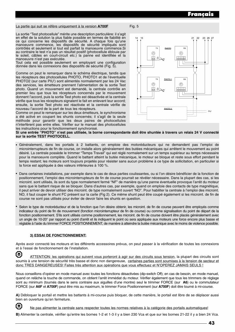
La partie qui suit se réfère uniquement à la version A700F Fig. 5
La sortie “Test photocellule” mérite une description particulière: il s’agiten effet de la solution la plus fiable possible en termes de fiabilité ence qui concerne les dispositifs de sécurité. A chaque fois qu’unemanoeuvre commence, les dispositifs de sécurité impliqués sontcontrôlés et seulement si tout est parfait la manoeuvre commence.Siau contraire le test n’a pas un résultat positif (photocellule éblouie parle soleil, câbles en court-circuit etc.) la panne est identifiée et lamanoeuvre n’est pas exécutée.Tout cela est possible seulement en employant une configurationdonnée dans les connexions des dispositifs de sécurité (Fig. 5).
Comme on peut le remarquer dans le schéma électrique, tandis queles récepteurs des photocellules PHOTO, PHOTO1 et de l’éventuellePHOTO2 (sur carte PIU’) sont alimentés normalement par les 24 Vacdes services, les émetteurs prennent l’alimentation de la sortie Testphoto. Quand un mouvement est demandé, la centrale contrôle enpremier lieu que tous les récepteurs concernés par le mouvementdonnent l’accord, puis la sortie Test photo est désactivée et la centralevérifie que tous les récepteurs signalent le fait en enlevant leur accord;ensuite, la sortie Test photo est réactivée et la centrale vérifie denouveau l’accord de la part de tous les récepteurs.Comme on peut le remarquer sur les deux émetteurs, le synchronismea été activé en coupant les shunts concernés; il s’agit de la seuleméthode pour garantir que les deux paires de photocellulesn’interfèrent pas entre elles. Vérifier sur le manuel des photocellulesles instructions pour le fonctionnement synchronisé.Si une entrée “PHOTO” n’est pas utilisée, la borne correspondante doit être shuntée à travers un relais 24 V connectésur la sortie TEST PHOTOCELL.
Généralement, dans les portails à 2 battants, on emploie des motoréducteurs qui ne demandent pas l’emploi demicrointerrupteurs de fin de course, on installe alors généralement des butées mécaniques qui arrêtent le mouvement au pointdésiré. La centrale possède le trimmer “Temps Travail” qui est réglé normalement sur un temps supérieur au temps nécessairepour la manoeuvre complète. Quand le battant atteint la butée mécanique, le moteur se bloque et reste sous effort pendant letemps restant; les moteurs sont toujours projetés pour résister sans aucun problème à ce type de sollicitation, en particulier sila force est appliquée à des valeurs inférieures à 100 %.
Dans certaines installations, par exemple dans le cas de deux parties coulissantes, ou si l’on désire bénéficier de la fonction depositionnement, l’emploi des microinterrupteurs de fin de course pourrait se révéler nécessaire. Dans la plupart des cas, si lesmicroint. sont utilisés, ils sont du type normalement fermé “NF” de manière qu’une panne éventuelle provoque l’arrêt du moteursans que le battant risque de se bloquer. Dans d’autres cas, par exemple, quand on emploie des contacts de type magnétique,il peut arriver de devoir utiliser des microint. de type normalement ouvert “NO”. Pour habiliter la centrale à l’emploi des microint.NO, il faut couper le shunt FC présent sur la carte (Fig 2). Ce même shunt peut être coupé également si les microint. de fin decourse ne sont pas utilisés pour éviter de devoir faire les shunts en question.
Selon le type de motoréducteur et de la fonction que l’on désire obtenir, les microint. de fin de course peuvent être employés commeindicateur du point de fin de mouvement (fonction microinterrupteur de fin de course) ou comme signalisation du point de départ de lafonction positionnement. S’ils sont utilisés comme positionnement, les microint. de fin de course doivent être placés généralement avecun angle de 10-20° par rapport au point d’arrêt et ils indiquent le point où sera appliquée aux moteurs une force encore plus basse etréglable à l’aide du trimmer FORCE POSITIONNEMENT, de manière à atteindre la butée mécanique avec le moins de violence possible.
3) ESSAI DE FONCTIONNEMENT:
Après avoir connecté les moteurs et les différents accessoires prévus, on peut passer à la vérification de toutes les connexionset à l’essai de fonctionnement de l’installation.
ATTENTION: les opérations qui suivent vous porteront à agir sur des circuits sous tension, la plupart des circuits sontsoumis à une tension de sécurité très basse et donc non dangereuse, certaines parties sont soumises à la tension de secteur etdonc TRES DANGEREUSES! Faites très attention aux opérations que vous effectuez et N’OPEREZ JAMAIS SEULS !
Nous conseillons d’opérer en mode manuel avec toutes les fonctions désactivées (dip-switch Off); en cas de besoin, en mode manuel,quand on relâche la touche de commande, on obtient l’arrêt immédiat du moteur. Vérifier également que tous les trimmers de réglagesont au minimum (tournés dans le sens contraire aux aiguilles d’une montre) seul le trimmer FORCE (sur A6) ou le commutateurFORCE (sur A6F et A700F) peut être mis au maximum, le trimmer Force Positionnement (sur A700F) doit être tourné à mi-course.
A) Débloquer le portail et mettre les battants à mi-course puis bloquer, de cette manière, le portail est libre de se déplacer aussibien en ouverture qu’en fermeture.
Ne pas alimenter la centrale sans respecter toutes les normes relatives à la catégorie des portails automatiques!
B) Alimenter la centrale, vérifier qu’entre les bornes 1-2 et 1-3 il y a bien 230 Vca et que sur les bornes 21-22 il y a bien 24 Vca.
Français
43
TX PHOTO
PHOTO 1
PHOTO 2PIU'
RX
TX RX
14 21 22 23 26 2715
•
•
•

La partie qui suit concerne uniquement la version A700F
C) Vérifier que sur les bornes 14-15 il y a bien une tension de 24 Vac pour l’alimentation des émetteurs des photocellules.
Dès que la centrale est alimentée, les voyants (DEL) situés sur les entrées actives doivent s’allumer, en outre, quelques instantsplus tard, la DEL “OK” devra commencer à clignoter à un rythme régulier. Si tout cela ne se produit pas, couper immédiatementl’alimentation et contrôler soigneusement les connexions.
La DEL “OK” située au centre de la carte a pour fonction de signaler l’état de la logique interne: un clignotement régulier et aurythme d’1 à la seconde indique que le microprocesseur interne est actif et en attente de commandes. Quand le microprocesseurreconnaît une variation de l’état d’une entrée (aussi bien entrée de commande que dip-switch des fonctions), il génère un doubleclignotement rapide, même si la variation ne provoque pas d’effets immédiats. Un clignotement très rapide pendant 3 secondesindique que la centrale vient d’être alimentée et qu’elle est en train d’effectuer un test des parties internes, enfin un clignotementirrégulier et non constant indique que le test ne s’est pas correctement déroulé et qu’il y a donc un inconvénient.
D) Vérifier maintenant que les DEL relatives aux entrées avec contacts type NF sont allumées (toutes les sécurités sont actives)et que les DEL relatives aux entrées type NO sont éteintes (aucune commande présente), si cela ne se produit pas, contrôler lesconnexions et l’efficacité des différents dispositifs.
E) Vérifier le fonctionnement correct de tous les dispositifs de sécurité présents dans l’installation (arrêt d’urgence, photocellules,barres palpeuses etc...), chaque fois qu’ils interviennent, les DEL correspondantes HALTE, PHOTO, PHOTO2 doivent s’éteindre.
Il s’agit d’une vérification parmi les plus importantes et elle doit être effectuée avec la plus grande attention. La sécurité “active”du portail dépend en effet du fonctionnement correct des dispositifs de sécurité. Si le clignotant est un excellent instrument poursignaler l’état de danger et les limiteurs de couple sont un auxiliaire valable pour limiter les dommages, seule une installationcorrecte des dispositifs de sécurité permet de bloquer l’automatisme avant qu’il puisse provoquer des dégâts.
La partie qui suit concerne seulement la version A700F
F) Si les entrées microinterrupteurs de fin de course sont utilisées, il faut vérifier l’exactitude des connexions. Manoeuvrer unbattant à la fois et vérifier qu’une fois que le point désiré est atteint, le microint. de fin de course correspondant intervient enéteignant la DEL correspondante sur la centrale (ou en l’allumant si les microint. de fin de course montés sont du type NO).
Il faut vérifier maintenant si le mouvement s’effectue dans la bonne direction, c’est-à-dire qu’il faut contrôler la correspondanceentre le mouvement prévu par la centrale et le mouvement effectif des battants. Cette vérification est fondamentale, si ladirection est erronée, dans certains cas (par exemple en mode semi-automatique), le portail pourrait fonctionner régulièrement enapparence. En effet, le cycle OUVRE est semblable au cycle FERME avec la différence fondamentale que les dispositifs desécurité seront ignorés dans la manoeuvre de fermeture qui est normalement la plus dangereuse, et interviendront en ouvertureen provoquant une refermeture sur l’obstacle avec des effets désastreux!
G) Pour vérifier si le sens de rotation est exact, il suffit de donner une brève impulsion sur l’entrée Pas-à-Pas; la premièremanoeuvre effectuée par la centrale après qu’elle ait été alimentée est toujours OUVRE, il suffit donc de vérifier si le portail bougedans le sens de l’ouverture; enfin, si le mouvement s’est effectué dans le sens erroné, il faut:
1 - Couper l’alimentation2 - Inverser les connexions “OUVRE” et “FERME” du moteur ou des moteurs qui tournaient en sens contraire.
Après avoir effectué cette opération, il est bon de contrôler de nouveau le sens de rotation en répétant l’opération à partir du point “G”.
H) Après avoir vérifié toutes les connexions et contrôlé le sens de rotation des moteurs, il est possible d’essayer un mouvementcomplet des actionneurs; nous conseillons d’opérer toujours en mode manuel avec toutes les fonctions désactivées. Si on utilisecomme commande l’entrée Pas-à-Pas, le premier mouvement (après l’allumage) devra être en ouverture. En agissant sur lesentrées de commande, manoeuvrer le portail jusqu’au point d’ouverture, si tout s’est déroulé régulièrement, il est possible depasser au mouvement dans le sens de la fermeture et de déplacer le portail jusqu’au point d’arrêt correspondant.Il est préférable d’effectuer différentes manoeuvres ouvre-ferme afin d’évaluer les éventuels défauts dans la structure mécaniquede l’automatisation et de détecter la présence de points de frottement particuliers.
I) Contrôler ensuite l’intervention des dispositifs de sécurité. Dans la manoeuvre d’ouverture, PHOTO et PHOTO1 n’ont aucuneinfluence, en fermeture, elles provoquent l’arrêt du mouvement. Si la carte PIU’ est présente, essayer également lefonctionnement de l’entrée PHOTO 2, en fermeture elle n’a aucun effet, en ouverture, elle provoque l’arrêt du mouvement. lesdispositifs connectés à l’entrée HALTE agissent aussi bien en ouverture qu’en fermeture en provoquant toujours l’arrêt dumouvement.
Français
44
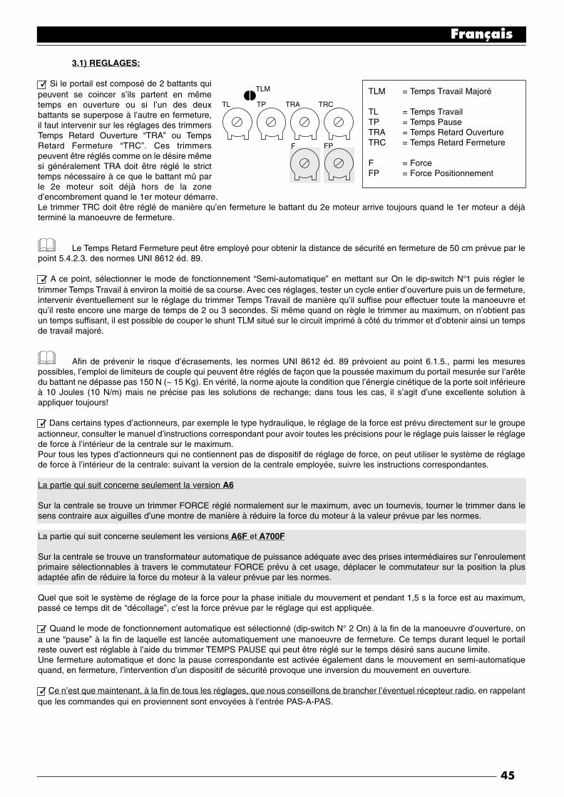
3.1) REGLAGES:
✓ Si le portail est composé de 2 battants quipeuvent se coincer s’ils partent en mêmetemps en ouverture ou si l’un des deuxbattants se superpose à l’autre en fermeture,il faut intervenir sur les réglages des trimmersTemps Retard Ouverture “TRA” ou TempsRetard Fermeture “TRC”. Ces trimmerspeuvent être réglés comme on le désire mêmesi généralement TRA doit être réglé le stricttemps nécessaire à ce que le battant mû parle 2e moteur soit déjà hors de la zoned’encombrement quand le 1er moteur démarre.Le trimmer TRC doit être réglé de manière qu’en fermeture le battant du 2e moteur arrive toujours quand le 1er moteur a déjàterminé la manoeuvre de fermeture.
Le Temps Retard Fermeture peut être employé pour obtenir la distance de sécurité en fermeture de 50 cm prévue par lepoint 5.4.2.3. des normes UNI 8612 éd. 89.
✓ A ce point, sélectionner le mode de fonctionnement “Semi-automatique” en mettant sur On le dip-switch N°1 puis régler letrimmer Temps Travail à environ la moitié de sa course. Avec ces réglages, tester un cycle entier d’ouverture puis un de fermeture,intervenir éventuellement sur le réglage du trimmer Temps Travail de manière qu’il suffise pour effectuer toute la manoeuvre etqu’il reste encore une marge de temps de 2 ou 3 secondes. Si même quand on règle le trimmer au maximum, on n’obtient pasun temps suffisant, il est possible de couper le shunt TLM situé sur le circuit imprimé à côté du trimmer et d’obtenir ainsi un tempsde travail majoré.
Afin de prévenir le risque d’écrasements, les normes UNI 8612 éd. 89 prévoient au point 6.1.5., parmi les mesurespossibles, l’emploi de limiteurs de couple qui peuvent être réglés de façon que la poussée maximum du portail mesurée sur l’arêtedu battant ne dépasse pas 150 N (~ 15 Kg). En vérité, la norme ajoute la condition que l’énergie cinétique de la porte soit inférieureà 10 Joules (10 N/m) mais ne précise pas les solutions de rechange; dans tous les cas, il s’agit d’une excellente solution àappliquer toujours!
✓ Dans certains types d’actionneurs, par exemple le type hydraulique, le réglage de la force est prévu directement sur le groupeactionneur, consulter le manuel d’instructions correspondant pour avoir toutes les précisions pour le réglage puis laisser le réglagede force à l’intérieur de la centrale sur le maximum.Pour tous les types d’actionneurs qui ne contiennent pas de dispositif de réglage de force, on peut utiliser le système de réglagede force à l’intérieur de la centrale: suivant la version de la centrale employée, suivre les instructions correspondantes.
La partie qui suit concerne seulement la version A6
Sur la centrale se trouve un trimmer FORCE réglé normalement sur le maximum, avec un tournevis, tourner le trimmer dans lesens contraire aux aiguilles d’une montre de manière à réduire la force du moteur à la valeur prévue par les normes.
La partie qui suit concerne seulement les versions A6F et A700F
Sur la centrale se trouve un transformateur automatique de puissance adéquate avec des prises intermédiaires sur l’enroulementprimaire sélectionnables à travers le commutateur FORCE prévu à cet usage, déplacer le commutateur sur la position la plusadaptée afin de réduire la force du moteur à la valeur prévue par les normes.
Quel que soit le système de réglage de la force pour la phase initiale du mouvement et pendant 1,5 s la force est au maximum,passé ce temps dit de “décollage”, c’est la force prévue par le réglage qui est appliquée.
✓ Quand le mode de fonctionnement automatique est sélectionné (dip-switch N° 2 On) à la fin de la manoeuvre d’ouverture, ona une “pause” à la fin de laquelle est lancée automatiquement une manoeuvre de fermeture. Ce temps durant lequel le portailreste ouvert est réglable à l’aide du trimmer TEMPS PAUSE qui peut être réglé sur le temps désiré sans aucune limite.Une fermeture automatique et donc la pause correspondante est activée également dans le mouvement en semi-automatiquequand, en fermeture, l’intervention d’un dispositif de sécurité provoque une inversion du mouvement en ouverture.
✓ Ce n’est que maintenant, à la fin de tous les réglages, que nous conseillons de brancher l’éventuel récepteur radio, en rappelantque les commandes qui en proviennent sont envoyées à l’entrée PAS-A-PAS.
Français
45
TLM = Temps Travail Majoré
TL = Temps TravailTP = Temps PauseTRA = Temps Retard OuvertureTRC = Temps Retard Fermeture
F = ForceFP = Force Positionnement
TLM
TL
F FP
TP TRA TRC

3.2) MODES DE FONCTIONNEMENT:
Note : quelques unes des parties décrites ci-après se réfèrent uniquement à la version A700F
Dans le fonctionnement en mode manuel, l’entrée OUVRE permet le mouvement en ouverture, l’entrée FERME permet lemouvement en fermeture. L’entrée PAS-A-PAS permet le mouvement alternativement en ouverture et en fermeture; dès que lacommande cesse en entrée le mouvement s’arrête. En ouverture, le mouvement s’arrête quand les microinterrupteurs de fin decourse interviennent ou en l’absence d’accord de la part de PHOTO2 (sur carte PIU’); en fermeture au contraire, le mouvements’arrête même si l’accord de PHOTO et de PHOTO1 manque. Aussi bien en ouverture qu’en fermeture une intervention sur HALTEprovoque toujours un arrêt immédiat du mouvement. Une fois qu’un mouvement s’est arrêté, il faut faire cesser la commande enentrée avant qu’une nouvelle commande puisse faire commencer un nouveau mouvement.
Dans le fonctionnement dans l’un des modes automatiques (Semi-automatique, Automatique ou Ferme toujours) une impulsionde commande sur l’entrée OUVRE provoque le mouvement en ouverture, si la commande persiste une fois l’ouverture obtenue,le mouvement reste “congelé” en une pause infinie; le portail ne pourra être refermé que lorsque la commande cessera. Uneimpulsion sur PAS-A-PAS provoque alternativement l’ouverture ou la fermeture. Une seconde impulsion sur PAS-A-PAS ou surl’entrée qui a commencé le mouvement provoque un Stop.Aussi bien en ouverture qu’en fermeture, une intervention sur HALTE provoque un arrêt immédiat du mouvement.
Le fait de maintenir dans une entrée de commande un signal continu au lieu d’une impulsion provoque un état de “prédominance”dans lequel les autres entrées de commande restent désactivées (utile pour connecter un temporisateur ou un sélecteur jour/nuit).
Si le mode de fonctionnement automatique est activé, après une manoeuvre d’ouverture, on a une pause à la fin de laquelle seproduit une fermeture. Si PHOTO ou PHOTO1 interviennent durant la pause, le temporisateur sera réinitialisé avec un nouveautemps; si au contraire on intervient durant la pause sur HALTE, la fonction de refermeture est effacée et on passe à un état deSTOP.
En ouverture l’intervention de PHOTO ou PHOTO1 n’a aucune influence tandis que PHOTO2 (sur carte PIU’) provoque l’inversiondu mouvement; en fermeture l’intervention de PHOTO ou PHOTO1 provoque une inversion du mouvement puis une pause puisune refermeture
4) PROGRAMMATION:
La centrale dispose d’une série de microinterrupteurs qui permettent d’activer différentes fonctions afin de rendre l’installation plusadaptée aux exigences de l’utilisateur et plus sûre dans les différentes conditions d’utilisation. Toutes les fonctions sont activéesquand le dip-switch correspondant est sur “On” tandis qu’elles sont désactivées quand le dip-switch correspondant est sur “Off”;certaines fonctions ne sont pas immédiatement efficaces et ont un sens seulement dans certaines conditions, par exemple lafonction N° 12 “Clignotant également en pause” est active uniquement avec la fermeture automatique et si la manoeuvre n’estpas interrompue avec une commande de HALTE.
ATTENTION: quelques unes des fonctions programmables sont liées à des aspects de la sécurité, évaluer trèsattentivement les effets d’une fonction et vérifier quelle est la fonction qui donne le plus de sécurité possible.Lors des opérations de maintenance d’une installation, avant de modifier une fonction programmable, évaluer la raison pourlaquelle certains choix avaient été faits en phase d’installation puis vérifier si avec la nouvelle programmation la sécurité se trouvecompromise.
4.1) FONCTIONS PROGRAMMABLES:
Les dip-switchs FONCTIONS permettent de sélectionner les différents modes de fonctionnement et d’insérer les fonctionsdésirées selon le tableau suivant:
Dip-switch 1-2 : Off Off = Mouvement “Manuel” (Homme Présent)On Off = Mouvement “Semi-automatique”Off On = Mouvement “Automatique” (Fermeture Automatique)On On = Mouvement “Automatique + Ferme Toujours”
Dip-switch 3 : On = Fonctionnement usage collectif <Non disponible en mode Manuel>Dip-switch 4 : On = PréclignotementDip-switch 5 : On = Referme juste après Photocellule <Seulement en mode Automatique>Dip-switch 6 : On = PHOTO1 également en ouvertureDip-switch 7 : On = Démarrage progressifDip-switch 8 : On = Arrêt progressifDip-switch 9: On = Coup de bélierDip-switch 10 : On = Eclairage de fonctionnement sur clignotant
Français
46

Dans la version A 700F se trouve un groupe de dip-switchs avec d’autres fonctions:
Dip-switch 11 : On = Fonction positionnement <Seulement avec utilisation microint. de fin de course>Dip-switch 12 : On = Clignotement également en Pause <Seulement en mode Automatique>Dip-switch 13 : On = Maintien pressionDip-switch 14 : On = Voyant Portail ouvert avec clignotement proportionnelDip-switch 15 : On = Activation test photocellulesDip-switch 16 : On = PHOTO et PHOTO1 également en ouvertureDip-switch 17 : On = PHOTO et PHOTO1 au début de la manoeuvre d’ouvertureDip-switch 18 : On = Saute STOP en ouvertureDip-switch 19 : On = Saute STOP en fermetureDip-switch 20 : On = FERME devient OUVRE PIETONS
• Nous rappelons que les fonctions qui sont possibles que dans certains cas sont signalées avec les notes entre les caractères “<>” après la description de la fonction.
• Naturellement, chaque dip-switch positionné sur “Off” n’active pas la fonction décrite
4.2) DESCRIPTION DES FONCTIONS:
Nous donnons maintenant une brève description des fonctions qui peuvent être activées en mettant sur “On” le dip-switchcorrespondant
Dip-switch 1-2: Off Off = Mouvement “Manuel” (Homme Présent)On Off = Mouvement “Semi-automatique”Off On = Mouvement “Automatique” (Fermeture Automatique)On On = Mouvement “Automatique + Ferme Toujours”
Dans le fonctionnement “Manuel”, le mouvement est exécuté seulement tant que la commande est active (touche enfoncée); en“Semi-automatique”, il suffit d’une impulsion de commande et tout le mouvement est exécuté jusqu’à ce que la butée mécaniquesoit atteinte ou jusqu’à l’intervention du microinterrupteur de fin de course. En mode de fonctionnement “Automatique”, après uneouverture on a une pause puis une fermeture. La fonction “Ferme Toujours” intervient si, après une coupure momentanée del’alimentation, le dispositif détecte le portail ouvert; dans ce cas, on a automatiquement une manoeuvre de fermeture précédéede 5 secondes de préclignotement.
Dip-switch 3: On = Fonctionnement usage collectif (non disponible en mode manuel)
Dans le fonctionnement usage collectif, une fois qu’une manoeuvre d’ouverture démarre, ce mouvement ne peut plus êtreinterrompu par d’autres impulsions de commande sur PAS-A-PAS ou OUVRE jusqu’à la fin du mouvement en ouverture. Dans lemouvement en fermeture, une nouvelle impulsion de commande provoque l’arrêt et l’inversion du mouvement en ouverture.
Dip-switch 4: On = Préclignotement
L’impulsion de commande provoque d’abord l’activation du clignotant puis après 5 secondes (2 s en mode manuel), le mouvementcommence.
Dip-switch 5: On = Referme juste après Photocellule (seulement en mode Automatique)
Cette fonction permet de garder le portail ouvert seulement le temps nécessaire au passage; en effet, après l’intervention dePHOTO et PHOTO1, la fermeture automatique aura lieu toujours après une pause de 5 secondes, indépendamment du Tempsde Pause programmé.
Dip-switch 6: On = PHOTO1 également en ouverture
Cette fonction est la seule qui diversifie le fonctionnement entre les photocellules PHOTO et PHOTO1. Normalement, les sécuritésPHOTO et PHOTO1 interviennent seulement dans la manoeuvre de fermeture tandis qu’elles n’ont aucun effet en ouverture.Si le dip-switch N°6 est mis sur “On”, PHOTO continue à intervenir seulement en fermeture mais PHOTO1 intervient aussi enouverture en provoquant une interruption du mouvement; en mode Semi-Automatique ou Automatique, on aura la reprise dumouvement en ouverture juste après le dégagement de la photocellule PHOTO1.Ce type de fonctionnement redevient utile pour arrêter la manoeuvre du portail en ouverture quand, par exemple, un véhicules’approche du portail du côté interne et donc dans la direction du mouvement, sans arrêter toutefois le mouvement quand levéhicule s’approche du côté externe.
Dip-switch 7: On = Démarrage progressif
Le début du mouvement est effectué de manière progressive en envoyant une force de plus en plus grande au moteur en formantune rampe qui dure environ 1 s de manière à garantir un démarrage sans secousses. (Déconseille sur l’opérateur METRO).
Français
47

Dip-switch 8: On = Arrêt progressif
Quand le mouvement s’achève, on a un arrêt progressif effectué en envoyant une force de plus en plus faible au moteur avec undécrément qui dure environ 1 s, ce qui garantit un arrêt sans secousses.Pour des raisons évidentes de sécurité, l’arrêt progressif ne se produit pas et est remplacé par un arrêt normal quand on al’intervention de HALTE , PHOTO et PHOTO1 ou PHOTO2 (sur carte PIU’) ou bien de l’un des microinterrupteurs de fin de course.
Dip-switch 9: On = Coup de bélier
Quand on utilise des actionneurs reversibles, quand le portail ne reste pas fermé avec uniquement la poussée des moteurs, ildevient indispensable d’installer une serrure électrique (voir les instructions des actionneurs pour le mode d’emploi).Sur la serrure électrique, on pourrait avoir la poussée naturelle qui tend à porter les battants en position légèrement ouverte,parfois cette poussée est si élevée qu’elle maintient le mécanisme de déclenchement de la serrure électrique bloqué.Avec la fonction Coup de bélier activée, avant de commencer une manoeuvre d’ouverture, il faut activer un cycle bref de fermeturequi, dans tous les cas, ne crée aucun effet de mouvement vu que les battants sont déjà sur la butée mécanique de fermeture. Decette manière, quand la serrure électrique est activée, elle se trouvera déchargée de toute force et donc libre de se déclencher.
Dip-switch 10: On = Eclairage de fonctionnement sur clignotant
Dans certains cas, on peut avoir besoin d’un éclairage sur la zone de mouvement du portail et on demande souvent que l’éclairages’éteigne automatiquement peu après la conclusion de la manoeuvre. Cette fonction est couramment appelée “Eclairage defonctionnement”. En connectant des corps d’éclairage sur la même sortie que le clignotant (pour une puissance maximum globalede 100 W) et en activant cette fonction, on obtiendra que durant tout le mouvement ou pendant 60 autres secondes, la sortierestera active en permettant l’éclairage de la zone.
Seulement dans la version A 700F se trouve un groupe de dip-switchs avec d’autres fonctions:
Dip-switch 11: On = Fonction positionnement <Seulement avec utilisation microint. de fin de course>
Au lieu d’être employés comme signalisation des limites du mouvement, les microinterrupteurs de fin de course peuvent êtreutilisés comme indication du point où se déclenche le positionnement. Généralement, quand on utilise la fonction positionnement,les microinterrupteurs de fin de course sont positionnés avec un angle de 10-20° avant la butée mécanique. De cette manière,quand lors du mouvement du battant le microinterrupteur de fin de course est atteint, une force moins grande sera envoyée aumoteur, à travers le réglage du trimmer “Force Positionnement”, pendant 3 autres secondes, de sorte que le battant atteigne l’arrêtmécanique avec le moins de violence possible.
Dip-switch 12: On = Clignotement également en Pause
Normalement, le clignotant est activé seulement durant le mouvement en ouverture ou en fermeture, cette fonction prévoit que leclignotant reste actif même durant la Pause, afin de signaler l’état de “fermeture prochaine”.
Dip-switch 13: On = Maintien pression
Dans les actionneurs hydrauliques, la poussée pour maintenir le portail fermé est développée dans un circuit hydraulique qui restesous pression. Quand le temps et l’usure réduise l’étanchéité du circuit hydraulique, il peut arriver qu’après quelques heures lapression interne tombe avec risque de légère ouverture des battants du portail.Si l’on active la fonction Maintien Pression, après 4 heures, puis toutes les 4 heures durant la fermeture du portail, une brèvemanoeuvre de fermeture est activée seulement dans le but de recharger la pression du circuit hydraulique.
N.B.: Les fonctions “Coup de bélier” et “Maintien Pression” ont un sens et ne sont effectuées que si le portail est fermé. La logiqueinterne considère le portail comme fermé si le microinterrupteur de fin de course FCC est intervenu ou, quand les microint. de fin decourse ne sont pas utilisés, si la précédente manoeuvre de fermeture est terminée régulièrement suite à la fin du temps de travail.
Dip-switch 14: On = Voyant Portail ouvert avec clignotement proportionnel
Normalement, le voyant Portail Ouvert indique l’état du portail selon les états suivants:
Eteint : Portail complètement ferméAllumé : Portail même seulement partiellement ouvertClignotement lent : Portail en phase d’ouvertureClignotement rapide : Portail en phase de fermeture
Le clignotement du voyant durant le mouvement peut être rendu proportionnel, de lent, progressivement à rapide et vice versa demanière à avoir une indication de l’état d’ouverture ou de fermeture.
Dip-switch 15: On = Activation test photocellules
Permet de lancer une phase de test sur les photocellules avant de commencer tout mouvement; de cette manière, en éliminanttoute possibilité de mauvais fonctionnement, on augmente la sécurité de l’installation. Pour exploiter la fonction Test Photo, il fautque les émetteurs des photocellules soient connectés à la sortie prévue à cet usage (noir Notes sur les connexions).
Français
48

Dip-switch 16: On = PHOTO et PHOTO1 également en ouverture
Normalement les sécurités PHOTO et PHOTO1 interviennent seulement dans la manoeuvre de fermeture, si le dip-switch N° 16est activé, l’intervention des dispositifs de sécurité provoque une interruption du mouvement également en ouverture. Si on esten mode semi-automatique ou Automatique, on aura la reprise de nouveau du mouvement en ouverture juste après ledégagement de la photocellule.
Dip-switch 17: On = PHOTO et PHOTO1 au début de la manoeuvre d’ouverture
Généralement, les dispositifs de sécurité PHOTO et PHOTO1 ne sont pas actifs dans la manoeuvre d’ouverture mais seulementdans la manoeuvre de fermeture car c’est la plus dangereuse. Dans certains pays, il y a des normes qui imposent le contrôle desdispositifs de sécurité au moins au début également de la manoeuvre d’ouverture. S’il faut respecter ces normes ou si l’on désireaugmenter le niveau de sécurité, il est possible d’activer la fonction et donc, avant de commencer le mouvement, de vérifierl’accord des sécurités PHOTO et PHOTO1 et seulement après commencer la manoeuvre.
Dip-switch 18: On = Saute STOP en ouverture
Le cycle du Pas-à-Pas est normalement: OUVRE-STOP-FERME-STOP, avec cette fonction activée, le cycle Pas-à-Pas devient:OUVRE-FERME-STOP-OUVRE tandis que l’entrée Ouvre perd la possibilité de faire STOP .
Dip-switch 19: On = Saute STOP en fermeture
Comme la fonction précédente mais relative au cycle FERME, le cycle Pas-à-Pas devient donc: OUVRE-STOP-FERME-OUVRE,tandis que l’entrée Ferme perd la possibilité de faire STOP
N.B: En mettant sur On les dip-switchs 18 et 19 le cycle pas-à-pas devient OUVRE-FERME-OUVRE en perdant définitivement lapossibilité de faire stop.
Dip-switch 20: On = FERME devient OUVRE PIETONS
Il peut arriver qu’il ne soit pas nécessaire d’ouvrir complètement le portail par exemple pour permettre le passage d’un piéton;dans ce cas, la fonction OUVRE PIETONS devient utile car elle permet d’ouvrir seulement le battant connecté au 2e moteur enlaissant l’autre fermé. Cette ouverture est activée par l’entrée FERME qui perd sa fonction d’origine pour devenir comme l’entréePas-à-Pas mais pour l’ouverture d’un seul battant. Il faut préciser que le cycle d’ouverture piétons s’active seulement en partantde la position portail fermé. Si par contre le portail est en mouvement ou ouvert, l’impulsion d’entrée n’a aucun effet.
ACCESSOIRE : CARTE EXPANSIONS “ PIU’ “
La centrale électronique dispose de toutes les principales fonctions demandées dans une automatisation normale, dans la versionA700F on a prévu la possibilité d’ajouter la carte en option PIU’ qui permet d’augmenter les possibilités de la centrale.
La partie qui suit concerne seulement la version A700F
La carte doit être introduite dans le connecteur prévu à cet effet dans la centrale, les bornes de la carte mettent à disposition:
• Les entrées suivantes:
Photo 2 = Dispositif de sécurité avec intervention dans la manoeuvre d’ouvertureOuverture Partielle = Exécute une manoeuvre d’ouverture en un temps réduit
• Les sorties suivantes:
Rouge = Lumière rouge du feu \Verte = Lumière verte du feu | AlarmesSerrure électrique = Commande de la serrure électrique (vu que la centrale dispose déjà de cette sortie, la
fonction a été modifiée en “Ventouse” pour connecter les dispositifs de retenue magnétique qui sont utilisés en alternative à la serrure électrique)
Eclairage de fonction. = Commande d’une lampe avec fonction d’éclairage de fonctionnement
N.B.: Les sorties peuvent commander seulement des charges de petite puissance (voyants, relais, etc.)
• et les réglages suivants:
Temps Partiel = Temps pour l’ouverture partielleTemps Fonct. = Temps pour l’éclairage de fonctionnement
Les caractéristiques complètes et le mode d’emploi de la carte se trouvent dans le manuel d’instructions spécifique.
Français
49

CARACTERISTIQUES TECHNIQUES DE LA CENTRALE:
Alimentation : 230 Vac ± 20%, 50 HzPuissance maximum actionneurs : deux moteurs d’ 1/2 Hp avec condensateur maximum de 20 µFPuissance maximum clignotant : 100 W à 230 Vac ( la sortie présente une tension fixe)
Courant Max. services 24 Vac : 200 mACourant Max sortie test photo. : 100 mAPuissance maximum voyant P.O. : 2 W (24 Vac)Puissance maximum serrure électr. : 25 W (12 Vac)Temps travail : de 2,5 à 40 s (de 30 à 80 s avec TLM)Temps pause : de 5 à 80 sTemps retard ritaritardorirdo ouverture TRA : 0 ou de 2.5 à 12 s (retard démarrage 1er moteur en ouverture)Temps retard fermeture TRC : 0 ou de 2.5 à 12 s (retard démarrage 2e moteur en fermeture)Réglage force : de 0 à 100% sur version A6; 30-45-60-80-100% sur version A6F et A700F Température de fonctionnement : -20 ÷ 70 °C
Dimensions : 280 x 220 x 110Poids : 2,7 Kg environIndice de protection : IP 55
Nice s.r.l. se réserve le droit d’apporter des modifications aux produits à tout moment sans préavis.
Français
50
NOTES FINALES:
Le présent manuel est destiné exclusivement au personnel technique qualifié pour l’installation.
• Aucune information contenue dans ce fascicule ne peut être considérée comme intéressante pour l’utilisateur final!
• Aucun réglage contenu dans ce fascicule ne peut être exécuté par l’utilisateur final!
✓ Quand l’installation est terminée, informer en détail par écrit l’utilisateur final sur le mode d’emploi du portail automatique,sur les risques résiduels, sur le mode de déblocage manuel en cas de manque d’énergie électrique.
✓ Informer le propriétaire de l’installation sur la nécessité d’une maintenance approfondie et constante, en particulier sur lanécessité d’un contrôle périodique des dispositifs de sécurité et des limiteurs de couple.
Dieses Handbuch ist nur für Techniker bestimmt, die für die Installation qualifiziert sind.Für den Endbenutzer ist keine der in diesem Band enthaltenen Informationen von Wichtigkeit!
Dieser Band wird zusammen mit den Artikeln A6, A6F und A700F geliefert und darf nicht für andere Produkte verwendet werden!
WICHTIG:
Die in diesem Band beschriebene Zentrale ist für die Steuerung einer oder zwei elektromechanischer Antriebe für dieAutomatisierung von Türen oder Toren bestimmt. Jeder andere Gebrauch ist unsachgemäß und daher von den gültigenVorschriften verboten.
Es ist unsere Pflicht, Sie daran zu erinnern, dass Sie Arbeiten an Maschinenanlagen ausführen, die in die Kategorie der“automatischen Tore und Türen” eingeordnet worden sind und daher als besonders “gefährlich” betrachtet werden. Ihre Aufgabeist es, diese so weit wie möglich sicher zu machen!
Die Installation und eventuelle Wartungsarbeiten dürfen nur von erfahrenem Fachpersonal ausgeführt werden, das diebesten, fachgemässen Anweisungen zu befolgen und in Übereinstimmung mit den Verordnungen der folgenden Gesetze,italienischen Normen oder europäischen Richtlinien vorzugehen hat:
• Norm UNI 8612 (motorisierte Tore und Türen: Baukriterien und Unfallverhütungseinrichtungen)
• DPR N°46 del 5/03/1990 (Normen für die Sicherheit der Elektroanlagen, befähigtes Personal)
• Dlgs N°459/96 del 24/07/96 (Annahme der Richtlinie 89/392 CEE, Maschinenrichtlinie)
• Dlgs N°615/96 del 12/11/96 (Annahme der Richtlinie 89/336 CEE, Richtlinie über die Elektromagnetische Kompatibilität)
• Dlgs N°626/96 del 26/11/96 (Annahme der Richtlinie 93/68 CEE, Richtlinie für Niederspannung)
Bei der Projektierung und Konstruktion ihrer Produkte beachtet Nice (was die Apparaturen betrifft) all diese Vorschriften, es istjedoch grundlegend, dass die gleichen Normen auch vom Installateur (was die Anlagen betrifft) mit der gleichen Genauigkeit undSorgfalt beachtet werden.
Personal, das kein Fachpersonal ist oder die für die Kategorie “Automatische Tore und Türen” anwendbaren Vorschriften nicht kennt,darf absolut keine Installationen und Anlagen ausführen.
Wer Anlagen ausführt, ohne die anwendbaren Vorschriften zu beachten:haftet für eventuelle Schäden, welche die Anlage verursachen kann!
INHALT:
Schnellanleitung Seite 521 Einleitung 541.1 Beschreibung 54 2 Installationsanleitungen 552.1 Installation 552.2 Schaltplan 562.3 Beschreibung der Anschlüsse 572.4 Anmerkungen bezüglich der Anschlüsse 583 Prüfung 593.1 Einstellungen 613.2 Betriebsarten 624 Programmierung 624.1 Programmierbare Funktionen 624.2 Beschreibung der Funktionen 63
Zubehör : Erweiterungskarte PIU’ 65Technische Merkmale der Zentrale 66
Deutsch
51
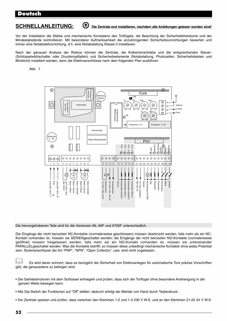
SCHNELLANLEITUNG: Die Zentrale erst installieren, nachdem alle Anleitungen gelesen worden sind!
Vor der Installation die Stärke und mechanische Konsistenz des Torflügels, die Beachtung der Sicherheitsfreiräume und derMindestabstände kontrollieren. Mit besonderer Aufmerksamkeit die anzubringenden Sicherheitsvorrichtungen bewerten undimmer eine Notabstellvorrichtung, d.h. eine Notabstellung Klasse 0 installieren.
Nach der genauen Analyse der Risikos können die Zentrale, die Kolbentorantriebe und die entsprechenden Steuer-(Schlüsselwählschalter oder Druckknopftafeln) und Sicherheitselemente (Notabstellung, Photozellen, Sicherheitsleisten undBlinklicht) installiert werden, dann die Elektroanschlüsse nach dem folgenden Plan ausführen:
Abb. 1
Die hervorgehobenen Teile sind für die Versionen A6, A6F und A700F unterschiedlich.
Die Eingänge der nicht benutzten NC-Kontakte (normalerweise geschlossen) müssen überbrückt werden, falls mehr als ein NC-Kontakt vorhanden ist, müssen sie SERIENgeschaltet werden; die Eingänge der nicht benutzten NO-Kontakte (normalerweisegeöffnet) müssen freigelassen werden, falls mehr als ein NO-Kontakt vorhanden ist, müssen sie untereinanderPARALLELgeschaltet werden. Was die Kontakte betrifft, so müssen diese unbedingt mechanische Kontakte ohne jedes Potentialsein; Stufenanschlüsse der Art “PNP”, “NPN”, “Open Collector”, usw. sind nicht zugelassen.
Es wird daran erinnert, dass es bezüglich der Sicherheit von Elektroanlagen für automatische Tore präzise Vorschriftengibt, die genauestens zu befolgen sind.
• Die Getriebemotoren mit dem Schlüssel entriegeln und prüfen, dass sich der Torflügel ohne besondere Anstrengung in der ganzen Weite bewegen kann.
• Alle Dip-Switch der Funktionen auf “Off” stellen, dadurch erfolgt der Betrieb von Hand durch Tastendruck.
• Die Zentrale speisen und prüfen, dass zwischen den Klemmen 1-2 und 1-3 230 V W.S. und an den Klemmen 21-22 24 V W.S.
Deutsch
52
Schließ
t
Öffnet
Schrittzyklus
Photozelle 1
Photozelle
Halt
Kontrollam
pe Tor Öffen
Gem
ein
24 V W
.S. (Z
ubehör)
Max 200 m
A
Endschalter Ö
ffnet 2
Endschalter S
chließt 2
Endschalter Ö
ffnet 1
Endschalter S
chließt 1
Gem
ein
Photozellentest
24 V W
.S. m
ax. 100 mA
Elektroschloss
Motor 2 S
chließt
Motor 2 G
emei
Motor 2 Ö
ffnet
Motor 1 S
chließt
Motor 1 G
emei
Motor 1 Ö
ffnet
LUC
Y 230 V
W.S
.M
ax 100 W
Linie 230 V W
.S. "N
"
Erde I
Linie 230 V W
.S. "L"
12 V W
.S., M
ax. 25 W
Schließ
t
Öffnet
Schrit-tzyklus
Photozelle 1
Photozelle
Halt
FC
A 2
FC
C 2
FC
A 1
FC
C 1
Prim
ärtransform
atorSicherung
Sicherung TLM
TL
OK
FC
F FP
TP44
43
42
41
TRA
Funktionen 1-10 Funktionen 11-20
TRC500mA
M12 2
M2
5 AF
1 2 3 4 5 6 7 8 9 10 11 12 13 14 15 16 17 18 19 20 21 22 23 24 25 26 27 28 29 30
Gemeinrelais
Funk
PIU'
Sekundärtransform
ator
Anlassrelais
programm
ierterM
ikroprozessor
Relais Öffnet/Schließt
Antenne
2. Kana
Funk

vorhanden sind; die LEDS an den Eingängen der NC-Kontakte müssen aufleuchten und die “OK”-Leuchtdiode muss einmal proSekunde blinken.
Falls die Endschalter installiert sind, müssen in der Version A700F die vier Leuchtdioden FCA1, FCA2 FCC1 und FCC2kontrolliert werden; bei geschlossenen Torflügeln dürfen sich nur die zwei FCC Leds ausschalten, wenn sie geöffnet sind, nur diezwei FCA Leds.
Falls es sich um den ersten Bewegungsvorgang handelt, nachdem die Zentrale gespeist worden ist, mit halb geöffnetenTorflügeln, so dass sie sich frei in beide Laufrichtungen bewegen können, einen kurzen Steuerimpuls auf den Eingang ÖFFNEToder auf SCHRITTZYKLUS geben. Sollte sich der Torflügel nun nicht in Richtung Öffnung bewegt haben, muss die elektrischeSpeisung abgeschaltet werden, dann die Anschlüsse der Motoren an den Klemmen 6-8 oder 9-11 umkehren; abschließend erneutprüfen, ob die Laufrichtung korrekt ist.
Nun eine ganze Bewegung ausführen, bis die mechanischen Anschlagpunkte erreicht werden oder die Endschalter eingreifen,dann die umgekehrte Bewegung versuchen.
In die Zentrale ist gemäfl der Vorschriften UNI 8612 Ausgabe 89 ein Drehmomentbegrenzer eingebaut; die KRAFT je nach Versionmit dem speziellen Trimmer oder dem Umschalter am Transformator einstellen, so dass der Schub am Auflenpunkt des Torflügelsnicht grüsser als 150 N (etwa 15 Kg) ist.
Falls man eine halbautomatische oder automatische Bewegung wählen will, muss der Trimmer ARBEITSZEIT so eingestelltwerden, dass man 2-3 Sekunden mehr als die für die Bewegung notwendige Zeit zur Verfügung hat.
Nur wenn die automatische Betriebsart gewählt worden ist, darf der Trimmer PAUSEZEIT beliebig geregelt werden.
An der Steuerzentrale sind zwei Trimmer für die Einstellung der VERZUGSZEIT ÖFFNUNG und der VERZUGSZEITSCHLIEßUNG vorhanden. Falls verlangt, den Verzug in Öffnung so einstellen, dass sich die Torflügung während der Bewegungnicht anstoßen, und die Verzugszeit in Schließung so regeln, dass der zweite Torflügel den ersten überlappt.
Die Dip-Switch der FUNKTIONEN wie gewünscht einstellen:
Switch 1-2: Off Off = “Manuelle” Bewegenung, bzw. Person anwesendOn Off = “Halbautomatische” BewegungOff On = “Automatische” Bewegung, bzw. Automatisches SchließenOn On = “Automatische + Schließt Immer” Bewegung
Switch 3 On = Wohnblockbetrieb < nicht in der Manuellen Betriebsart>Switch 4 On = VorblinkenSwitch 5 On = Schließt sofort nach der Photozelle wieder < nur in Automatatischem Betrieb >Switch 6 On = Photozelle1 auch in ÖffnungSwitch 7 On = Allmähliches Anfahren < Sollte auf METRO getriebemotoren nicht verwendet werden>Switch 8 On = Allmähliches AnhaltenSwitch 9 On = Druckstoß Switch 10 On = Höflichkeitslicht am Blinklicht
Nur in der Version A700F ist eine zweite Dip-Switch Gruppe mit anderen Funktionen vorhanden:
Switch 11 On = Funktion Positionieren < nur mit Benutzung der Endschalter >Switch 12 On = Blinkt auch in Pause < nur in Automatischem Betrieb>Switch 13 On = DruckerhaltungSwitch 14 On = Kontrollampe T.O. mit ProportionalblinkenSwitch 15 On = Aktivierung PhotozellentestSwitch 16 On = Photozelle und Photozelle1 auch in ÖffnungSwitch 17 On = Photozelle und Photozelle1 bei Beginn des ÖffnungsvorgangsSwitch 18 On = Überspringt STOP in Öffnet Switch 19 On = Überspringt STOP in SchließtSwitch 20 On = SCHLIEßT wird zu ÖFFNET FUßGÄNGER
Wir erinnern daran, dass gewisse Funktionen nur in bestimmten Fällen möglich sind, andere werden nur nach besonderenEreignissen ausgeführt; die Anmerkungen zwischen “<>” nach der Beschreibung der Funktion beachten.
Dann die verschiedenen Bewegungen mit den soeben eingestellten Funktionen versuchen; mit besonderer Aufmerksamkeit dieWirksamkeit der Sicherheitsvorrichtungen und der Notabstellung untersuchen.
Den Endbenutzer genau über die Bedienung des automatischen Tors, die Restgefahren, die manuelle Entriegelung beiStromausfall, die Notwendigkeit einer sorgfältigen und konstanten Wartung und insbesondere über die Notwendigkeit einerregelmäßigen Kontrolle der Sicherheitsvorrichtungen und der Drehmomentbegrenzer informieren.
Deutsch
53
•
•
•
•
•
•
•
•
•

1) EINLEITUNG:
Die elektronische Zentrale kann benutzt werden, um die Bewegung von Toren und automatischen Türen zu steuern; sie kann anelektromechanische Kolbentorantriebe angeschlossen werden, die mit Einphasen-Asynchrommotor mit 230 V W.S. Spannungbetrieben werden, wie zum Beispiel die von Nice hergestellten Modelle PLUTO PL 4000 oder METRO ME 3000.
Diese Betriebsanleitung bezieht sich auf mehrere Versionen der gleichen Zentrale, die verschiedenen Versionen unterscheidensich außer der unterschiedlichen Methode für die Kontrolle der Kraft der Antriebe auch durch ihre Wahl an programmierbarenFunktionen und zur Verfügung stehenden Eingängen:
A6 : Basisversion, elektronische Kraftregelung durch PhasendrosselungA6F : Basisversion, elektromechanische Kraftregelung mit umschaltbarem SpartransformatorA700F : Komplette Version, elektromechanische Kraftregelung mit umschaltbarem Spartransformator
Die Zentrale erlaubt den Betrieb auf “manuell”, “halbautomatisch” oder “automatisch”; während der Bewegung werden dieZustimmungen der Sicherheitsvorrichtungen (Eingänge HALT, PHOTOZELLE, PHOTOZELLE1) kontrolliert; in der Version A700Fwerden die Bewegungsgrenzen mittels Endschalter überprüft, wogegen die Bewegung in der Version A6 auf Zeit ist.Die Zentrale verfügt über hoch entwickelte, logische Funktionen, die vom “Speicher der Bewegung” über “Schließt immer” bis zu“Schließt sofort wieder nach Photozelle” reichen, und über besondere Betriebsfunktionen wie “allmähliches Anfahren”,“allmähliches Anhalten”.In der Ausführung A700F stehen durch die Installation der Erweiterungskarte “PIU’ “ mit anderen Ein- und Ausgängen noch mehrFunktionen zur Verfügung.Alle Zentralen sind für die Installation der großen Auswahl an Funkempfängern, von Nice hergestellt, vorbereitet.
Für das Projekt wurden die fortschrittlichsten Techniken angewendet, um die höchste Störungsfreiheit, beste Einsatzflexibilität undgrößte Wahl an programmierbaren Funktionen zu gewährleisten.
1.1) BESCHREIBUNG:
Mit Hinsicht auf die Besonderheit des Produktes und den Gebrauch von Techniken, die nicht mit jenen für andere ähnlicheProdukte verglichen werden können, wird vor der Installation der Zentrale und der Ausführung der Anschlüsse eine kurzeBeschreibung der wichtigsten Elemente der Karte gegeben.
Abb. 21: Speisetransformator (nur A6)2: Steckverbindungen für externen Spartransformator
(nur A6F oder A700F)3: 500 mA Schnellsicherung auf 24 V W.S. Speisung4: Steckverbindung für FUNK-Karte5: Trimmer für die Einstellung der Zeiten6: Klemmenbrett Antenne und Ausgang 2. FUNKkanal7: Dip-Switch für die Wahl der Funktionen8: Steckverbindung für Erweiterungskarte PIU’ (nur A700F)9: Led für die Meldung des Zustandes der Eingänge10: Klemmenbrett Eingänge Sicherheiten und Steuerungen11: Klemmenbrett Endschaltereingänge (nur A700F)12: Klemmenbrett Ausgänge Elektroschloss und
Photozellentest (nur A700F)13: Klemmenbrett Ausgänge Blinklicht und Motoren14: Klemmenbrett 230 V W.S. Speisung15: 5A Schnellsicherung auf 230 V W.S. Speisung16: OK-Leuchtdiode17: Trimmer für die Einstellung der Kraft18: FC Überbrückung für normalerweise geöffnete Endschalter
Die “OK”-Leuchtdiode (16) hat die Aufgabe, den korrekten Betrieb der internen Logik zu melden: ein regelmäßiges Blinken einmalpro Sekunde bedeutet, dass der interne Mikroprozessor aktiv ist und auf Steuerungen wartet. Wenn der Zustand der Eingänge(10 - 11) oder die Dip-Switch der Funktionen (7) geändert werden, wird ein doppeltes Schnellblinken erzeugt, auch wenn dieÄnderung keine sofortigen Wirkungen hat. Wenn die Zentrale gespeist ist, leuchten die Kontrollampen (9) an den Eingängen auf, falls der Eingang aktiv und die 24 V W.S.Steuerspannung an ihm vorhanden ist. Gewöhnlich sind die Leuchtdioden an den Eingängen der Sicherheiten HALT,PHOTOZELLE und PHOTOZELLE1 und jene der Endschalter immer eingeschaltet, wogegen jene an den SteuereingängenSCHRITTZYKLUS, ÖFFNET und SCHLIEßT gewöhnlich ausgeschaltet sind.
Deutsch
54
FC
A 2
FC
C 2
FC
A 1
FC
C 1
Sicherung
Sicherung
TLM
TL
OK
FC
F FP
TP44
43
42
41
TRA
Funktionen 1-10 Funktionen 11-20
TRC500mA
5 AF
1 2 3 4 5 6 7 8 9 10 11 12 13 14 15 16 17 18 19 20 21 22 23 24 25 26 27 28 29 30
Funk
PIU'
1 23 4 5
6
7
8
9
1012 111314
15
16
18
17
Schließ
t
Öffnet
Schrit-tzyklus
Photozelle 1
Photozelle
Halt

2) INSTALLATIONSANLEITUNGEN:
DieZentrale erst installieren, nachdem alle Anweisungen für die Zentrale und die Kolbentorantriebe gelesen worden sind.
Vor der Installation die Stärke und mechanische Konsistenz des Torflügels, die Beachtung der Sicherheitsfreiräume und derMindestabstände kontrollieren. Alle Anweisungen in den Betriebsanleitungen der Getriebemotoren genauestens befolgen.
Eine genaue und sorgfältige Analyse der mit der Automatisierung verbundenen Risikos durchführen, besonders genaudie anzubringenden Sicherheitsvorrichtungen bewerten und immer eine Notabstellvorrichtung, d.h. eine Notabstellung Klasse 0,installieren. Es wird daran erinnert, dass es bezüglich der Sicherheit von Elektroanlagen für automatische Tore präziseVorschriften gibt, die genauestens zu befolgen sind!
Über diese Vorschriften hinaus, die sich auf Elektroanlagen allgemein, die Anlagen von Maschinen und die automatischen Türenund Tore beziehen, werden hier weitere spezifische Anmerkungen für diese Zentrale gegeben, mit denen die Anlage noch sichererund zuverlässiger wird.
Die Speiseleitung zur Zentrale hin muss immer durch einen magnetthermischen Schalter oder ein Paar 5A Sicherungen geschütztwerden, ein Differentialschalter ist zu empfehlen, jedoch nicht unbedingt notwendig, falls bereits einer vor der Anlage besteht.
Die Zentrale mit einem 3 x 1,5 mm2 Kabel (Phase - Sternpunktleiter + Erdleiter) speisen; sollte die Entfernung zwischen Zentraleund Anschluss an die Erdanlage größer als 30 m sein, muss für einen Erdschluss in der Nähe der Zentrale gesorgt werden.
Sollten die Motoren ohne Kabel sein, muss ein Kabel Typ 4 x 1,5 mm2 (öffnet + schließt + Gemein + Erde) benutzt werden; dieseKabel müssen immer kürzer als 3 m sein.
Absolut vermeiden, Verbindungen zu Kabeln in unterirdischen Kästen zu machen, auch wenn diese ganz dicht sind.
Für die Anschlüsse des Sicherheitsteils mit Niedrigstspannung (Klemmen 12...30) Kabel mit Mindestschnitt gleich 0,25 mm2
benutzen; nur für das Elektroschloss Kabel mit mindestens 1 mm2 Schnitt verwenden. Abschirmkabel für mehr als 30 m langeKabel benutzen und die Beflechtung nur an der Seite der Zentrale erden.
Immer und nur Kabel verwenden (verschiedene, separat isolierte Leiter mit einer zusätzlichen, generellen Isolierung), niemalseinzelne Leiter, auch nicht, wenn sie in spezielle Schienen verlegt sind.
Sicherstellen, dass alles nötige zur Verfügung steht und dass das Material für diesen Einsatz geeignet ist.
2.1) INSTALLATION:
Die Kolbentorantriebe unter genauer Befolgung aller Anweisungen in den Betriebsanleitungen installieren, die den Motorenbeigefügt sein müssen. Sollten Widersprüche zwischen den Anweisungen der Antriebe und diesem Handbuch festgestelltwerden, die Installation erst ausführen, nachdem jeder Zweifel beseitigt worden ist und mit der Lieferfirma der Antriebe oderUNSEREM TECHNISCHEM BÜRO Kontakt aufnehmen.
Eine korrekte Wahl bei der Installation der Zentrale ist für die Sicherheit und den richtigen Schutz vor Witterung grundlegend.Bedenken Sie auch, dass die Zentrale Teile mit Netzspannung und elektronische Komponenten enthält, die an und für sichbesonders empfindlich sind.Die Zentrale wird in einem Gehäuse geliefert, der bei richtiger Installation einen Schutzgrad von IP55 garantiert (gemäßCEI 70-1 und IEC 529), und ist daher auch für die Installation im Freien geeignet.Trotzdem müssen einfache, aber wesentliche Regeln beachtet werden:
Die Zentrale auf eine unbewegliche Fläche montieren, die vollkommen eben und vor Stößen geschützt sein muss.
Das Gehäuse der Zentrale mit passenden Mitteln so befestigen, dass der untere Teil mindenstens 40 cm Abstand vom Erdreich hat.Für die Art der Befestigung die Anweisungen am Ende dieses Handbuchs befolgen.
Spezielle Kabelführungen oder Kabelrohre nur in den unteren Teil der Zentrale einsetzen, die Seitenwände und die obere Wanddürfen auf keinen Fall gelocht werden. Die Kabel dürfen nur von der unteren Seite her in die Zentrale eingehen.!
Falls Leitungen benutzt werden, die sich mit Wasser füllen könnten oder diese Leitungen aus einem unterirdischen Schachtkommen, müssen die Kabel zuerst in eine Abzweigdose auf gleicher Höhe mit der Zentrale geleitet werden, dann die Kabel vonder Abzweigdose aus immer durch den unteren Teil in das Gehäuse der Zentrale leiten. Auf diese Weise wird vermieden, dasssich durch eventuelle Wasserverdampfung Kondenswasser in der Zentrale bilden kann.
Deutsch
55
•
•
•
•
•
•
•
•
•
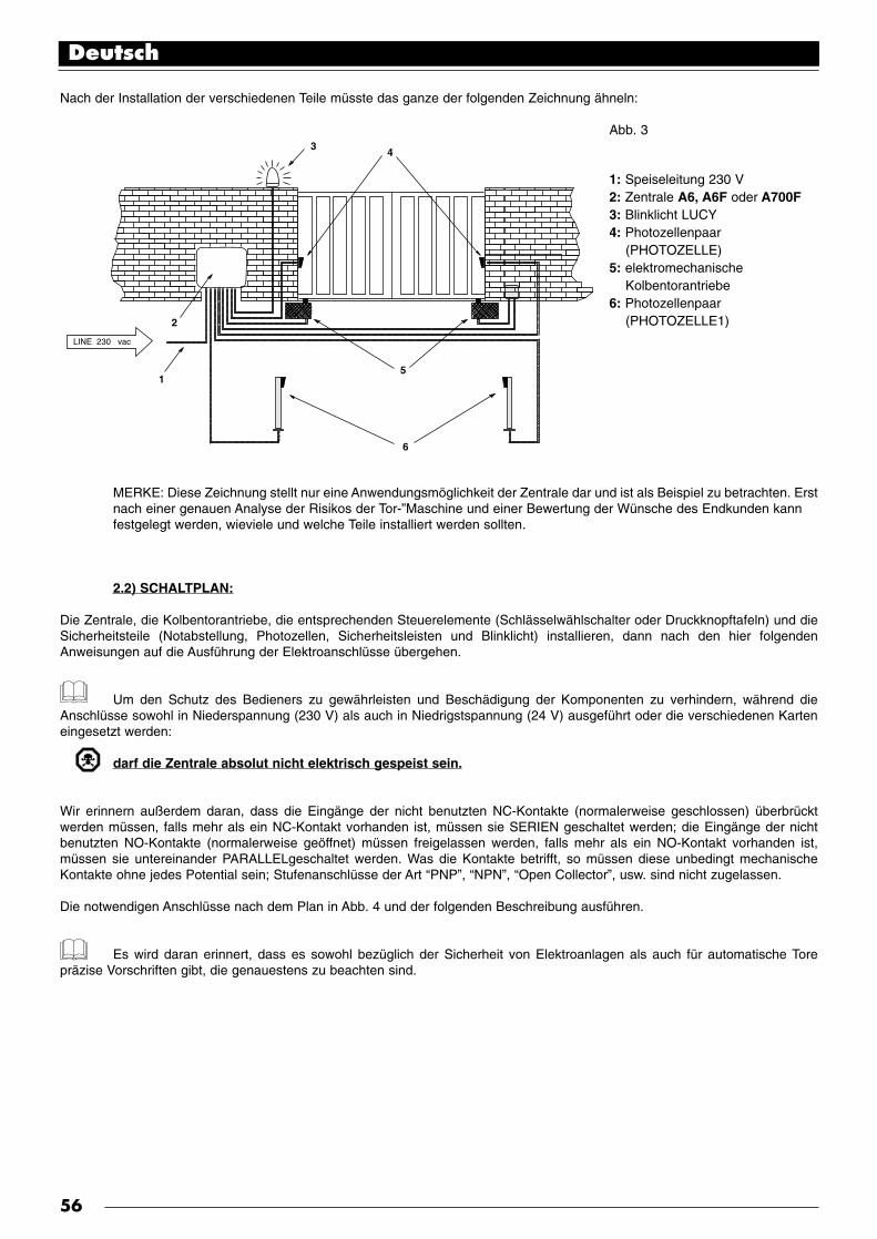
Nach der Installation der verschiedenen Teile müsste das ganze der folgenden Zeichnung ähneln:
Abb. 3
1: Speiseleitung 230 V2: Zentrale A6, A6F oder A700F3: Blinklicht LUCY4: Photozellenpaar
(PHOTOZELLE) 5: elektromechanische
Kolbentorantriebe6: Photozellenpaar
(PHOTOZELLE1)
MERKE: Diese Zeichnung stellt nur eine Anwendungsmöglichkeit der Zentrale dar und ist als Beispiel zu betrachten. Erstnach einer genauen Analyse der Risikos der Tor-”Maschine und einer Bewertung der Wünsche des Endkunden kann festgelegt werden, wieviele und welche Teile installiert werden sollten.
2.2) SCHALTPLAN:
Die Zentrale, die Kolbentorantriebe, die entsprechenden Steuerelemente (Schlässelwählschalter oder Druckknopftafeln) und dieSicherheitsteile (Notabstellung, Photozellen, Sicherheitsleisten und Blinklicht) installieren, dann nach den hier folgendenAnweisungen auf die Ausführung der Elektroanschlüsse übergehen.
Um den Schutz des Bedieners zu gewährleisten und Beschädigung der Komponenten zu verhindern, während dieAnschlüsse sowohl in Niederspannung (230 V) als auch in Niedrigstspannung (24 V) ausgeführt oder die verschiedenen Karteneingesetzt werden:
darf die Zentrale absolut nicht elektrisch gespeist sein.
Wir erinnern außerdem daran, dass die Eingänge der nicht benutzten NC-Kontakte (normalerweise geschlossen) überbrücktwerden müssen, falls mehr als ein NC-Kontakt vorhanden ist, müssen sie SERIEN geschaltet werden; die Eingänge der nichtbenutzten NO-Kontakte (normalerweise geöffnet) müssen freigelassen werden, falls mehr als ein NO-Kontakt vorhanden ist,müssen sie untereinander PARALLELgeschaltet werden. Was die Kontakte betrifft, so müssen diese unbedingt mechanischeKontakte ohne jedes Potential sein; Stufenanschlüsse der Art “PNP”, “NPN”, “Open Collector”, usw. sind nicht zugelassen.
Die notwendigen Anschlüsse nach dem Plan in Abb. 4 und der folgenden Beschreibung ausführen.
Es wird daran erinnert, dass es sowohl bezüglich der Sicherheit von Elektroanlagen als auch für automatische Torepräzise Vorschriften gibt, die genauestens zu beachten sind.
Deutsch
56
6
1
LINE 230 vac
2
3 4
5

Abb. 4
Der hervorgehobene Teil ist nur in der Version A700F vorhanden.Der hervorgehobene Teil ist in den Version A6F und A700F vorhanden.
Die Installation und spätere Wartungseingriffe dürfen nur von erfahrenem Fachpersonal, in Übereinstimmung mit derVerordnung DPR Nr. 46 vom 5/3/1990, unter voller Beachtung der Normen UNI 8612 und der besten Fachkenntnisse ausgeführtwerden. Wer diese Eingriffe ausführt, haftet für die eventuell verursachten Schäden.
2.3) BESCHREIBUNG DER ANSCHLÜSSE:
Hier geben wir eine kurze Beschreibung der möglichen Anschlüsse der Zentrale nach außen.
1...3 : 230 V W.S. = Elektrische Speisung 230 VW.S. 50 Hz
4-5 : Blinklicht = Ausgang für den Anschluss an das 230 V W.S. Blinklicht, Höchstleistung der Lampe 100 W
6...8 : Motor 1 = Ausgang für den Anschluss an den 1. 230 V W.S. Motor, Höchstleistung des Motors 1/2 Hp
9...11 : Motor 2 = Ausgang für den Anschluss an den 2. 230 V W.S. Motor, Höchstleistung des Motors 1/2 Hp
Merke: Die Motoren 1 und 2 unterscheiden sich lediglich durch den Verzug beim Start; der 1. Motor ist an die VerzugszeitÖffnung “TRA” gebunden, wogegen der 2. Motor an die Verzugszeit Schließung “TRC” gebunden ist. Falls keine Verzugszeiten benötigt werden, gibt es keinen Unterschied zwischen den zwei Motoren.
Deutsch
57
FC
A 2
FC
C 2
FC
A 1
FC
C 1
44
43
42
41
Funktionen 11-20
500mA
M12 2
M2
5 AF
1 2 3 4 5 6 7 8 9 10 11 12 13 14 15 16 17 18 19 20 21 22 23 24 25 26 27 28 29 30
PIU'
Schließ
t
Öffnet
Schrittzyklus
Photozelle 1
Photozelle
Halt
Kontrollam
pe Tor Öffen
Gem
ein
24 V W
.S. (Z
ubehör)
Max 200 m
A
Endschalter Ö
ffnet 2
Endschalter S
chließt 2
Endschalter Ö
ffnet 1
Endschalter S
chließt 1
Gem
ein
Photozellentest
24 V W
.S. m
ax. 100 mA
Elektroschloss
Motor 2 S
chließt
Motor 2 G
emein
Motor 2 Ö
ffnet
Motor 1 S
chließt
Motor 1 G
emein
Motor 1 Ö
ffnet
LUC
Y 230 V
W.S
.M
ax 100 W
Linie 230 V W
.S. "N
"
Erde I
Linie 230 V W
.S. "L"
12 V W
.S., M
ax. 25 W
Schließ
t
Öffnet
Schrit-tzyklus
Photozelle 1
Photozelle
Halt
Sicherung
Sicherung
Funktionen 1-10
Funk
Antenne
2. Kana
Funk

Die Folgenden Klemmen sind nur in der Version A6F und A700F vorhanden:
12-13 : Elektroschloss = Ausgang 12 V W.S., für die Aktivierung des Elektroschlosses, Höchstleistung 25 W
Folgende Klemmen sind nur in der Version A700F vorhanden:
14-15 : Photozellentest = Ausgang 24 V W.S., für die Speisung der Sender der Photozellen, höchstens 100 mA
16 : Gemein = Gemein für die Endschaltereingänge (wie die andere gemeine Klemme 23)
17 : Endschalter C1 = Eingang für Endschalter Schließt des Motors 1
18 : Endschalter A1 = Eingang Endschalter Öffnet des Motors 1
19 : Endschalter C2 = Eingang Endschalter Schließt des Motors 2
20 : Endschalter A2 = Eingang Endschalter Öffnet des Motors 2
21-22 : 24 V W.S. = 24 V W.S. Ausgang für die Speisung der Zubehörteile (Photozelle, Funk, usw.), höchstens 200 mA
23 : Gemein = Gemein für alle Eingänge (als Gemein kann auch die Klemme 22 benutzt werden)
24 : Kontrollampe T.O.= Ausgang für Kontrollampe Tor Offen 24 V W.S., Höchstleistung der Kontrollampe 2 W
25 : Halt = Eingang mit HALT-Funktion (Notfall, Verriegelung oder extreme Sicherheit)
26 : Photozelle = Eingang für Sicherheitsvorrichtungen (Photozellen, Sicherheitsleisten)
27 : Photozelle1 = Eingang für weitere Sicherheitsvorrichtung (Photozellen, Sicherheitsleisten)
28 : Schrittzyklus = Eingang für zyklischen Betrieb (ÖFFNET STOP SCHLIEßT STOP)
Folgende Klemmen sind nur in der Version A700F vorhanden:
29 : Öffnet = Eingang für Öffnung (gegebenenfalls durch eine Uhr geschaltet)
30 : Schließt = Eingang für Schließung
41-42 : 2° Funkkanal = Ausgang des eventuellen, zweiten Kanals des Funkempfängers
43-44 : Antenne = Eingang für die Antenne des Funkempfängers
Auf der Karte der Zentrale sind zwei Steckverbinder für Sonderkarten vorhanden:
RADIO = Steckverbinder für Funkempfänger, von Nice hergestellt
PIU’ = Steckverbinder für Erweiterungskarte PIU’ (nur für die Version A700F)
Es wird empfohlen, die eventuellen Sonderkarten RADIO oder PIU’ erst nach Beendigung der Installation und nach Überprüfungder Betriebstüchtigkeit der Anlage einzubauen. Die Sonderkarten sind für den Betrieb nicht notwendig und erschweren die Suchenach eventuellen Defekten.
2.4) ANMERKUNGEN bezüglich der ANSCHLÜSSE:
Der Großteil der Anschlüsse ist sehr einfach, die meisten sind direkt mit nur einem Abnehmer oder Kontakt verbunden, bei einigenist die Verbindung etwas schwieriger:
Für den korrekten Betrieb aller Einphase-Asynchronmotoren wird ein Kondensator benötigt; einige Getriebemotoren, zum Beispieldas Modelll PLUTO PL 4000, von Nice hergestellt, sind bereits mit innen angeschlossenem Kondensator ausgestattet, beianderen muss dagegen der Kondensator außen angeschlossen werden, was zum Beispiel für das Modell METRO ME 3000 gilt,das ebenso von Nice hergestellt wird. In diesem Fall muss der Kondensator zwischen den Motorphasen ÖFFNET und SCHLIEßTangeschlossen werden. Der Einfachheit halber sollte der Kondensator direkt im dazu bestimmten Raum in der Zentraleangebracht werden.
Deutsch
58

Der folgende Teil bezieht sich nur auf die Version A700F Abb. 5
Eine besondere Beschreibung verdient der Ausgang“Photozellentest”, hier handelt es sich einfach um die bestmöglicheLösung, was die Zuverlässigkeit der Sicherheitsvorrichtungen betrifft.Jedesmal, wenn eine Bewegung erfolgen soll, werden die damitbetroffenen Sicherheitsvorrichtungen kontrolliert, und erst, wenn allesin Ordnung ist, kann die Bewegung beginnen.Falls der Test dagegen zu keinem positiven Ergebnis führt (die Photozelleist durch die Sonne geblendet, kurzgeschlossene Kabel, usw.), wird derDefekt festgestellt und die Bewegung wird nicht ausgeführt.All dies ist nur durch eine bestimmte Gestaltung der Anschlüsse derSicherheitsvorrichtungen möglich (Abb. 5).
Wie im Schaltplan bemerkt werden kann, werden die Empfänger derPhotozellen PHOTOZELLE, PHOTOZELLE1 und eventuellPHOTOZELLE2 (auf der Karte PIU’) gewöhnlich von den 24 V W.S. derZubehörteile gespeist, wogegen die Sender die Speisung vom AusgangPhotozellentest nehmen. Wenn eine Bewegung gefordert wird, wirdzuerst kontrolliert, dass alle von der Bewegung betroffenen Empfängerdie Zustimmung geben, dann wird der Ausgang Photozellentestabgeschaltet und geprüft, ob alle Empfänger das Ereignis melden unddie Zustimmung verweigern; am Ende wird der Ausgang Photozellentestwieder aktiviert und die Zustimmung aller Empfänger erneut geprüft.Wie bemerkt werden kann, wurde an den zwei Sendern durch das Durchtrennen der Überbrückungen der Synchronismusaktiviert; das ist die einzige Methode, um zu gewährleisten, dass sich die zwei Photozellenpaare nicht gegenseitig stören. In derBetriebsanleitung der Photozellen die Anweisungen für den Synchronbetrieb überprüfen.Sollte ein Eingang der Photozellen nicht benutzt werden, muss die jeweilige Klemme durch ein Relais mit 24V W.S., anden Ausgang Photozellentest angeschlossen, überbrückt werden.
Gewöhnlich werden für Zweiflügeltore Getriebemotoren verwendet, die keine Endschalter benötigen; üblicherweise werdenmechanische Endanschläge installiert, welche die Bewegung am gewünschten Punkt anhalten. In der Zentrale ist auch derTrimmer “Arbeitszeit” vorhanden, der gewöhnlich auf eine Zeit eingestellt wird, die etwas länger als die Zeit der vollständigenBewegung ist. Wenn der Torflügel den mechanischen Endanschlag erreicht, blockiert sich der Motor und bleibt die restliche Zeitüber beansprucht; die Motoren sind immer so projektiert, dass sie dieser Beanspruchung problemlos widerstehen, vor allem,wenn die Kraft unter Werten von 100 % ist.
In einigen Installationen, zum Beispiel bei zwei Schiebetorflügeln oder falls die Funktion Positionieren ausgenutzt werden soll,könnten Endschalter nötig sein. Großteils handelt es sich dabei um “NC” Endschalter, so dass ein eventueller Defekt dasAnhalten des Motors verursacht, ohne dass der Torflügel auflaufen kann. In anderen Fällen, wenn zum Beispiel magnetischeKontakte benutzt werden, kann es vorkommen, dass “NO” Endschalter benutzt werden müssen. Um die Zentrale für dieBenutzung der NO-Endschalter zu aktivieren, muss die Überbrückung FC auf der Karte (Abb. 2) durchgeschnitten werden.Diese Überbrückung kann auch durchgeschnitten werden, falls die Endschalter nicht benutzt werden, wodurch vermieden wird,die entsprechenden Überbrückungen durchzuführen.
Je nach Typ des Getriebemotors und der Funktion, die erzielt werden soll, können die Endschalter als Anzeiger desBewegungsendpunktes (Endschalterfunktion) oder als Meldung des Anfangspunktes der Funktion Positionieren benutzt werden. DieEndschalter müssen gewöhnlich in einem Winkel von 10-20° ab dem Anhaltepunkt verlegt werden, wenn sie zum Positionieren benutztwerden, und geben den Punkt an, an dem eine noch geringere Kraft an den Motoren angebracht wird, die mit dem Trimmer KRAFTPOSITIONIEREN eingestellt werden kann, so dass der mechanische Endanschlag mit der geringst möglichen Heftigkeit erreicht wird.
3) PRÜFUNG:
Nachdem die Anschlüsse der Motoren und der verschiedenen, vorgesehenen Zubehörteile ausgeführt worden sind, kann auf dieÜberprüfung aller Anschlüsse und die Prüfung der Anlage übergegangen werden.
ACHTUNG: bei den nächsten Arbeiten werden sie mit Kreisläufen unter Spannung arbeiten, großteils der Kreisläufehaben niedrigste Sicherheitsspannung und sind daher nicht gefährlich, einige Teile haben Netzspannung und sind daher SEHRGEFÄHRLICH! Daher sehr aufmerksam und NIE ALLEIN arbeiten!
Es wird empfohlen, auf manuell und mit allen Funktionen deaktiviert (Dip-Switch auf Off) vorzugehen, wenn die Steuertaste immanuellen Betrieb losgelassen wird, erfolgt das sofortige Anhalten des Motors. Außerdem prüfen, ob alle Einstell-Trimmer auf demMinimum sind (gegen den Uhrzeigersinn gedreht), nur der Trimmer KRAFT (in A6) oder der Umschalter KRAFT (in A6F undA700F) kann auf das Maximum gestellt werden, der Trimmer Kraft Positionieren (in A700F) muss auf halben Weg gestellt werden.
A) Das Tor entriegeln und die Torflügel auf die Hälfte ihres Laufs bringen, dann blockieren; das Tor kann sich dadurch sowohl inÖffnung als auch in Schließung frei bewegen.
Die Zentrale nicht speisen, wenn nicht alle Vorschriften für die Klasse der automatischen Tore beachtet werden!
Deutsch
59
TX Photozelle
PIU'
RX
TX RX
14 21 22 23 26 2715
Photozelle 1
Photozelle 2
•
•
•
B) Die Zentrale speisen und prüfen, dass zwischen den Klemmen 1-2 und 1-3 230 V W.S. und an den Klemmen 21-22 24 V W.S.vorhanden sind.
Der folgende Teil bezieht sich nur auf die Version A700F
C) Überprüfen, dass an den Klemmen 14-15 eine Spannung von 24 V W.S. für die Speisung der Photozellensender vorhanden ist.
Sobald die Zentrale gespeist wird, müssen die Kontrollampen (LEDs) an den aktiven Eingängen aufleuchten, außerdem muss die“OK”-Led nach ein paar Augenblicken regelmäßig zu blinken beginnen. Sollte das alles nicht erfolgen, sofort den Stromwegnehmen und die Anschlüsse genauer kontrollieren.
Die in der Mitte der Karte angeordnete “OK”-Leuchtdiode hat die Aufgabe, den Zustand der internen Logik zu melden: einregelmäßiges Blinken einmal pro Sekunde bedeutet, dass der interne Mikroprozessor aktiv ist und auf Steuerungen wartet. Wennder Mikroprozessor dagegen eine Änderung des Zustandes eines Eingangs wahrnimmt (sowohl Steuereingang als auch Dip-Switchder Funktionen), erzeugt er ein doppeltes Schnellblinken, auch wenn die Änderung keine sofortigen Wirkungen hat. Ein 3 Sekundenlanges, sehr schnelles Blinken bedeutet, dass die Zentrale soeben gespeist worden ist und einen Test der internen Teile ausführt;ein unregelmäßiges und nicht konstantes Blinken bedeutet, dass der Test nicht positiv beendet wurde und daher ein Defekt vorliegt.
D) Nun prüfen, ob die Leds der Eingänge mit NC-Kontakten eingeschaltet (alle Sicherheiten aktiv) und die Leds der Eingänge mitNO-Kontakten ausgeschaltet sind (keine Steuerung vorhanden); sollte das nicht erfolgen, die Anschlüsse und dieLeistungsfähigkeit der verschiedenen Vorrichtungen kontrollieren.
E) Den korrekten Betrieb aller Sicherheitsvorrichtungen der Anlage überprüfen (Notabstellung, Photozellen, Sicherheitsleisten,usw.); bei jedem Eingriff dieser Vorrichtungen müssen sich die entsprechenden Leds HALT, PHOTOZELLE und PHOTOZELLE1ausschalten.
Diese Überprüfung ist eine der wichtigsten und muss immer mit größter Aufmerksamkeit gemacht werden; vom korrekten Betrieb derSicherheitsvorrichtungen hängt die gesamte “aktive” Sicherheit der Tormaschine ab. Auch wenn das Blinklicht ein optimales Gerät zurMeldung von Gefahren ist und die Drehmomentbegrenzer ein gültiges Hilfsmittel zur Begrenzung von Schäden sind, kann nur diekorrekte Installation der Sicherheitsvorrichtung gewährleisten, dass der Automatismus blockiert wird, bevor Schäden verursacht werden.
Der folgende Teil bezieht sich nur auf die Version A700F
F) Wenn die Endschaltereingänge benutzt werden, muss überprüft werden, ob die Anschlüsse richtig sind. Einen Torflügel nachdem anderen bewegen und prüfen, dass der Endschalter eingreift, wenn der gewünschte Punkt erreicht ist, wodurch dieentsprechende Led an der Zentrale ausgeschaltet wird (oder eingeschaltet wird, wenn NO-Endschalter installiert sind).
Nun muss geprüft werden, ob die Bewegung in die korrekte Richtung erfolgt, d.h. ob die von der Zentrale vorgesehene Bewegungmit der tatsächlichen Bewegung der Torflügel übereinstimmt. Diese Überprüfung ist wesentlich, wenn die Richtung verkehrt ist,könnte das Tor in einigen Fällen (zum Beispiel im halbautomatischen Betrieb) anscheinend ordnungsgemäß funktionieren, da inder Tat der Zyklus ÖFFNET dem Zyklus SCHLIEßT ähnlich ist, jedoch mit dem grundlegenden Unterschied, dass dieSicherheitsvorrichtungen beim Schließvorgang, der gewöhnlich der gefährlichste ist, ignoriert werden und bei der Öffnungeingreifen und ein erneutes Schließen verursachen werden, wobei das Hindernis mit verheerenden Wirkungen getroffen wird.
G) Um zu prüfen, ob die Drehrichtung korrekt ist, genügt ein kurzer Impuls auf den Eingang Schrittzyklus; die erste, von derZentrale ausgeführte Bewegung nach ihrer Speisung ist immer ÖFFNET, es genügt daher, zu prüfen, ob sich das Tor in dieÖffnungsrichtung bewegt; falls die Bewegung dagegen in die falsche Richtung erfolgte:
1 - muss die Speisung abgeschaltet werden2 - müssen die Anschlüsse “ÖFFNET” und “SCHLIEßT” des Motors oder der Motoren, die sich in die
entgegengesetzte Richtung drehten, umgekehrt werden.
Nachdem das beschriebene ausgeführt worden ist, erneut prüfen, ob die Drehrichtung korrekt ist und die Arbeiten in Punkt “G”wiederholen..
H) Nachdem alle Anschlüsse und die Drehrichtung der Motoren überprüft worden sind, kann eine vollständige Bewegung derTorantriebe versucht werden; es wird empfohlen, immer auf manuell und mit allen Funktionen deaktiviert vorzugehen. Wird alsSteuerung der Eingang Schrttzyklus verwendet, so muss die erste Bewegung (nach dem Einschalten) in Öffnung sein. DurchBetätigung der Steuereingänge das Tor bis zum Öffnungspunkt bewegen; wenn sich alles ordnungsgemäß abgespielt hat, kannauf die Schließbewegung übergegangen und das Tor bis zum Anhaltepunkt bewegt werden.Es ist besser, mehrere auf-zu Bewegungen auszuführen, um eventuelle Defekte der mechanischen Struktur der Automatisierungund das Vorhandensein besondere Reibungspunkte festzustellen.
I) Nun den Eingriff der Sicherheitsvorrichtungen testen, PHOTO und PHOTOZELLE1 haben in Öffnung keine Wirkung undverursachen in Schließung das Anhalten der Bewegung. Wenn die Karte PIU’ vorhanden ist, auch den Betrieb des EingangsPHOTOZELLE2 testen, in Schließung hat er keine Wirkung, in Öffnung wird das Anhalten der Bewegung verursacht. Die amEingang HALT angeschlossenen Vorrichtungen wirken sowohl in Öffnung als auch in Schließung und verursachen immer dasAnhalten der Bewegung.
Deutsch
60
•
•

3.1) EINSTELLUNGEN:
✓ Wenn das Tor aus 2 Flügeln besteht, diesich hindern können, falls sie in Öffnunggleichzeitig starten oder falls sich inSchließung ein Flügel über den anderen legt,müssen die Trimmer Verzugszeit Öffnung“TRA” oder Verzugszeit Schließung “TRC”eingestellt werden. Diese Trimmer könnenbeliebig eingestellt werden, auch wenn TRAgewöhnlich so wenig wie möglich eingestellt,so dass der vom 2. Motor bewegte Torflügelbereits außerhalb des Raumbedarfs ist, wennder 1. Motor startet.Der Trimmer TRC muss so eingestellt werden, dass in Schließung der Torflügel des 2. Motors immer ankommt, wenn der 1. Motordie Schließbewegung bereits beendet hat.
Die Verzugszeit Schließung kann für die Ausführung der 50 cm Freiraum in Schließung benutzt werden, in Punkt 5.4.2.3der Normen UNI 8612 Ausgabe 89 vorgesehen.
✓ Nun die Betriebsart “Halbautomatisch” wählen und den Dip-Switch Nr. 1 auf On stellen, dann den Trimmer Arbeitszeit auf etwahalben Weg regeln. Mit diesen Einstellungen einen ganzen Zyklus in Öffnung, dann einen in Schließung versuchen undgegebenenfalls den Trimmer Arbeitszeit so regulieren, dass während dieser Zeit ein ganzer Bewegungsvorgang ausgeführtwerden kann und noch eine Zeitspanne von 2 oder 3 Sekunden bleibt. Falls keine ausreichende Zeit erzielt wird, auch wenn derTrimmer auf das Maximum gestellt wird, kann die Überbrückung TLM auf der gedruckten Schaltplatte in der Nähe des Trimmersdurchgeschnitten und dadurch eine Arbeitsmehrzeit erhalten werden.
Unter den möglichen Maßnahmen zur Vermeidung von Quetschgefahr sehen die Normen UNI 8612 Ausgabe 89 imPunkt 6.1.5 die Benutzung von Drehmomentbegrenzern vor, die so eingestellt werden können, dass der Höchstschub des Tor, ander Kante des Torflügels gemessen, 150 N (~ 15 Kg) nicht überschreitet. In Wahrheit fügt die Norm die Bedingung hinzu, dass diekinetische Energie des Torflügels kleiner als 10 Joule (10 N/m) sein muss, sie klärt aber nicht, welche Methoden als Alternativebenutzt werden können; auf jeden Fall handelt es sich um eine sehr gute Lösung, die immer anzuwenden ist!
✓ In einigen Antrieben, zum Beispiel den öldynamischen Typen, ist die Kraftregelung direkt auf die Antriebsgruppe vorgesehen;für Erklärungen bezüglich der Einstellungen wird auf die Betriebsanleitung verwiesen, daher die Kraft in der Zentrale auf dasMaximum eingestellt halten.Für all jene Antriebstypen, die keine Kraftregelvorrichtung enthalten, kann dagegen das Kraftregelsystem in der Zentraleausgenutzt werden: je nach Version der benutzten Zentrale die entsprechenden Anweisungen befolgen.
Der folgende Teil bezieht sich nur auf die Version A6
An der Zentrale ist ein Trimmer KRAFT vorhanden, der gewöhnlich auf die Höchstkraft eingestellt ist; mit einem Schraubenzieherden Trimmer gegen den Uhrzeigersinn drehen, bis die Motorkraft auf den von der Norm vorgesehenen Wert reduziert wird.
Der folgende Teil bezieht sich nur auf die Versionen A6F und A700F
An der Zentrale ist ein Spartransformator mit geeigneter Leistung und Zwischeneingriffen auf die Primärwicklung vorhanden, diemit dem Umschalter KRAFT gewählt werden können; den Umschalter auf die beste Position verstellen, um die Motorkraft auf denvon den Vorschriften vorgesehenen Wert zu reduzieren.
Bei jedem Regelsystem der Kraft wird in der Anfangsphase der Bewegung und für eine Dauer von 1,5 Sekunden die Höchstkraftgegeben, nur nach dieser Zeit, auch “Anlaufzeit” genannt, wird die vorgesehene Kraft eingeschaltet.
✓ Bei Wahl der automatischen Betriebsweise (Dip-Switch Nr. 2 auf On) wird am Ende der Öffnungsbewegung eine “Pause”ausgeführt, der automatisch eine Schließbewegung folgt. Diese Zeit, in der das Tor geöffnet bleibt, kann mit dem TrimmerPAUSEZEIT ohne Einschränkungen und beliebig lang eingestellt werden.Ein automatisches Schließen und daher die entsprechende Pause erfolgen auch bei der Bewegung in halbautomatisch, inSchließung verursacht eine Sicherheitsvorrichtung die Umkehrung der Bewegung auf Öffnung.
✓ Wir empfehlen, erst nun, am Ende aller Einstellungen, den eventuellen Funkempfänger zu installieren, wobei zu bedenken ist,dass die von ihm kommenden Steuerungen zum Eingang SCHRITTZYKLUS geschickt werden.
Deutsch
61
TLM = Arbeitsmehrzeit
TL = ArbeitszeitTP = PausezeitTRA = Verzugszeit ÖffnungTRC = Verzugszeit Schließung
F = KraftFP = Kraft Positionieren
TLM
TL
F FP
TP TRA TRC

3.2) BETRIEBSARTEN:
Merke: einige der hier folgend beschriebenen Teile beziehen sich nur auf die Version A700F
Beim manuellen Betrieb erlaubt der Eingang ÖFFNET die Öffnungsbewegung und der Eingang SCHLIEßT die Schließbewegung.Der SCHRITTZYKLUS erlaubt die Bewegung abwechselnd in Öffnung und Schließung; sobald die Eingangssteuerung beendetist, hält die Bewegung an. In Öffnung stoppt die Bewegung, wenn die Endschalter eingreifen, oder die Zustimmung durchPHOTOZELLE2 fehlt (auf der Karte PIU’), in Schließung stoppt dagegen die Bewegung auch beim Fehlen der Zustimmung vonPHOTOZELLE und PHOTOZELLE1. Sowohl in Öffnung als auch in Schließung verursacht ein Eingriff auf HALT immer einsofortiges Anhalten der Bewegung. Nachdem eine Bewegung gestoppt ist, muss die Eingangssteuerung beendet werden, bevormit einer erneuten Steuerung eine neue Bewegung begonnen werden kann.
Bei einer der automatischen Betriebsarten (halbautomatisch, automatisch oder schließt immer) verursacht ein Steuerimpuls aufden Eingang ÖFFNET die Bewegung in Öffnung; falls die Steuerung bestehen bleibt, nachdem die Öffnung erreicht worden ist,bleibt die Bewegung in einer unendlichen Pause “eingefroren”; erst wenn die Steuerung aufhört, kann das Tor wiedergeschlossen werden. Ein Impuls auf SCHRITTZYKLUS verursacht abwechselndes Öffnen oder Schließen. Ein zweiter Impuls aufSCHRITTZYKLUS oder den gleichen Eingang, der die Bewegung begonnen hat, verursacht ein Stop.Der Eingriff auf HALT verursacht sowohl in Öffnung als auch in Schließung das sofortige Anhalten der Bewegung.
Wird an einen Steuereingang statt eines Impulses ein Dauersignal beibehalten, wird ein “Vorrang”-Zustand verursacht, in dem dieanderen Steuereingänge deaktiviert bleiben (nützlich für den Anschluss einer Uhr oder eines Tag-Nacht-Wählers).
Ist die automatische Betriebsweise gewählt, wird nach einer Öffnungsbewegung eine Pause ausgeführt und danach eineSchließung. Falls während der Pause ein Eingriff von PHOTOZELLE oder PHOTOZELLE1 erfolgt, wird der Zeitgeber auf eineneue Pausezeit rückgestellt; sollte dagegen während der Pausezeit ein Eingriff auf HALT erfolgen, wird die Wiederschließfunktiongelöscht und auf ein STOP übergegangen.
In Öffnung haben die Eingriffe von PHOTOZELLE und PHOTOZELLE1 keine Wirkung, wogegen die PHOTOZELLE2 (auf derKarte PIU’) die Umkehrung der Bewegung verursacht; in Schließung verursacht der Eingriff von PHOTOZELLE undPHOTOZELLE1 eine Umkehrung der Bewegung, dann eine Pause, dann ein erneutes Schließen.
4) PROGRAMMIERUNG:
Die Zentrale verfügt über eine Reihe Mikroschalter, mit denen die verschiedenen Funktionen aktiviert werden können, so dass dieAnlage dem Bedarf des Benutzers besser angepasst werden kann und unter den verschiedenen Einsatzbedingungen sicherer ist.Alle Funktionen werden aktiviert, indem der entsprechende Dip-Switch auf “On” gestellt wird, wogegen sie mit dem Dip-Switch auf“Off” nicht eingeschaltet sind; einige Funktionen haben keine sofortige Wirksamkeit und nur unter bestimmten Bedingungen einenSinn, zum Beispiel ist die Funktion Nr. 12 “Blinkt auch in Pause” nur in der automatischen Schließung aktiv und falls die Bewegungnicht mit einer HALT Steuerung unterbrochen wird.
ACHTUNG: einige der programmierbaren Funktionen sind an Sicherheitsaspekte gebunden; daher die Wirkungen einerFunktion sehr genau bewerten und überprüfen, welche die größtmögliche Sicherheit gibt.Bei der Wartung einer Anlage, bevor man eine programmierbare Funktion ändert, den Grund genau festlegen, warum bei derInstallation bestimmte Wahlen getroffen worden sind, dann überprüfen, ob die Sicherheit durch die neue Programmierungbeeinträchtigt wird.
4.1) PROGRAMMIERBARE FUNKTIONEN:
Mit dem Dip-Switch FUNKTIONEN können die verschiedenen Betriebsarten eingestellt und die gewünschten Funktion gemäß derfolgenden Tabelle eingeschaltet werden:
Switch 1-2: Off Off = “Manuelle” Bewegung, bzw. Person anwesendOn Off = “Halbautomatische” BewegungOff On = “Automatische” Bewegung, bzw. Automatische SchließungOn On = “Automatische + Schließt Immer” Bewegung
Switch 3 On = Wohnblockbetrieb <Nicht in der manuellen Betriebsart >Switch 4 On = VorblinkenSwitch 5 On = Schließt sofort wieder nach Photozelle < nur in automatisch >Switch 6 On = Photozelle1 auch in ÖffnungSwitch 7 On = Allmähliches AnfahrenSwitch 8 On = Allmähliches AnhaltenSwitch 9 On = DruckstoßSwitch 10 On = Höflichkeitslicht an Blinklicht
Deutsch
62

In der Version A700F ist eine zweite Dip-Switch Gruppe vorhanden, mit anderen Funktionen:
Switch 11 On = Fnktion Positionieren < nur mit Benutzung der Endschalter >Switch 12 On = Blinklicht auch in Pause < snur in automatisch >Switch 13 On = DruckerhaltungSwitch 14 On = Kontrollampe T.O. mit ProportionalblinkenSwitch 15 On = Aktivierung PhotozellentestSwitch 16 On = Photozelle und Photozelle1 auch in ÖffnungSwitch 17 On = Photozelle und Photozelle1 bei Beginn des ÖffnungsvorgangsSwitch 18 On = Überspringt STOP in ÖffnetSwitch 19 On = Überspringt STOP in SchließtSwitch 20 On = SCHLIEßT wird zu ÖFFNET FUßGÄNGER
• Wir erinnern daran, dass auf die Funktionen, die nur in bestimmten Fällen möglich sind, durch die Anmerkungen zwischen “<>”nach der Beschreibung der Funktion hingewiesen wird.
• Offensichtlich aktiviert jeder auf “Off” gestellte Dip-Swich die beschriebene Funktion nicht.
4.2) BESCHREIBUNG DER FUNKTIONEN:
Wir geben nun eine kurze Beschreibung der Funktionen, die eingeschaltet werden können, indem der entsprechende Dip-Switchauf “On” gestellt wird.
Switch 1-2: Off Off = “Manuelle” Bewegung (Person anwesend)On Off = “Halbautomatische” BewegungOff On = “Automatische” Bewegung (Automatisches Schließen)On On = “Automatische + Schließt Immer” Bewegung
In der “manuellen” Betriebsart wird die Bewegung nur bis zum Vorhandensein der Steuerung (Taste gedrückt) ausgeführt.In der “halbautomatischen” Betriebsart genügt ein Steuerimpuls, damit die gesamte Bewegung bis zum Erreichen desmechanischen Endanschlags oder dem Eingriff des Endschalters ausgeführt wird. In der “automatischen” Betriebsart folgt nacheiner Öffnung eine Pause und dann ein Schließen. Die Funktion “Schließt immer” greift nach einem momentanen Stromausfall ein; falls das offene Tor wahrgenommen wird, wirdautomatisch ein Schließvorgang gestartet, dem ein 5 Sekunden langes Vorblinken vorausgeht.
Switch 3: On = Wohnblockbetrieb <Nicht in der manuellen Betriebsart >
Im Wohnblockbetrieb kann nach dem Start einer Öffnungsbewegung die Bewegung nicht mehr durch andere Steuerimpulse aufSCHRITTZYKLUS oder ÖFFNET bis zum Ende der Öffnungsbewegung unterbrochen werden.In der Schließbewegung verursacht ein neuer Steuerimpuls das Anhalten und die Umkehrung der Öffnungsbewegung.
Switch 4: On = Vorblinken
Bei Steuerimpuls wird zuerst das Blinklicht aktiviert und nach 5 Sekunden (2 Sekunden in manueller Betriebsart) beginnt dieBewegung.
Switch 5: On = Schließt sofort wieder nach Photozelle (nur in Automatisch)
Mit dieser Funktion kann das Tor nur die für das Durchfahren notwendige Zeit geöffnet gehalten werden; nach dem Eingriff vonPHOTOZELLE oder PHOTOZELLE1 erfolgt das automatische Schließen immer mit 5 Sekunden Pause und unabhängig von dereingestellten Pausezeit.
Switch 6: On = Photozelle1 auch in Öffnung
Diese Funktion ist der einzige Unterschied zwischen der Betriebsweise von PHOTOZELLE und PHOTOZELLE1. Gewöhnlichgreifen die Sicherheiten PHOTOZELLE und PHOTOZELLE1 nur bei der Schließung ein und haben in Öffnung keine Wirkung.Wenn der Dip-Switch Nr. 6 auf “On” gestellt wird, greift PHOTOZELLE weiterhin nur in Schließung ein, PHOTOZELLE1 jedochauch in Öffnung und verursacht eine Unterbrechung der Bewegung. In halbautomatisch oder automatisch erfolgt erneut eineBewegung, wenn PHOTOZELLE1 wieder frei ist.Diese Betriebsart ist nützlich, um die Torbewegung zu stoppen, wenn sich dem Tor zum Beispiel ein Fahrzeug von der Innenseiteher und daher in die Richtung der Bewegung nähert, ohne gleichzeitig die Bewegung anzuhalten, wenn sich das Fahrzeug vonder Außenseite her nähert.
Switch 7: On = Allmähliches Anfahren
Der Beginn der Bewegung wird allmählich ausgeführt, indem dem Motor eine immer größere Kraft zugeschickt und eine Stufegebildet wird, die etwa 1 Sekunde lang dauert; dadurch wird garantiert, dass das Anfahren behutsam erfolgt. (Sollte auf METROgetriebemotoren nicht verwendet werden).
Deutsch
63

Switch 8: On = Allmähliches Anhalten
Wenn die Bewegung endet, wird ein allmähliches Anhalten ausgeführt, indem dem Motor eine immer kleinere Kraft zugeschicktwird, mit einer Verzögerung, die etwa 1 Sekunde lang dauert; dadurch wird garantiert, dass das Anhalten behutsam erfolgt.Aus offensichtlichen Sicherheitsgründen erfolgt das allmähliche Anhalten nicht, wenn HALT, PHOTOZELLE und PHOTOZELLE1oder PHOTOZELLE2 (auf der Karte PIU’) oder einer der Endschalter eingreifen, und wird durch ein normales Anhalten ersetzt.
Switch 9: On = Druckstoß
Wenn reversible Kolbentorantriebe benutzt werden und das Tor daher nicht allein durch den Schub der Motoren geschlossenbleibt, wird die Installation eines Elektroschlosses unbedingt nötig (für den Gebrauch siehe Anweisungen der Kolbentorantriebe).Am Elektroschloss könnte daher jener natürliche Schub vorhanden sein, der zu der leicht geöffneten Stellung der Torflügel führt,und manchmal ist dieser Schub so groß, dass der Einrastmechanismus des Elektroschlosses blockiert bleibt.Wenn die Funktion Druckstoß eingeschaltet ist, wird vor dem Beginn einer Öffnung ein kurzer Schließzyklus aktiviert, der jedochwirkungslos ist, da sich die Torflügel bereits am Endanschlag Schließung befinden. Das Elektroschloss wird jedoch dadurch nachseiner Aktivierung ohne jede Kraftbelastung sein und kann daher einrasten.
Switch 10: On = Höflichkeitslicht an Blinklicht
In bestimmten Fällen kann eine Beleuchtung in der Bewegungszone des Tors wünschenswert sein, und oft wird gewünscht, dasssich die Beleuchtung kurz, nachdem das Tor die Bewegung beendet hat, automatisch ausschaltet. Diese Funktion wird allgemein“Höflichkeitslicht” genannt. Wenn geeignete Leuchtkörper am Ausgang des Blinklichtes (für eine Gesamthöchstleistung von 100W) angeschlossen werden und diese Funktion aktiviert wird, so wird der Ausgang während der gesamten Bewegung und noch 60Sekunden danach aktiv bleiben und somit die Beleuchtung der Zone ermöglichen.
Nur in der Version A700F ist eine zweite Gruppe Dip-Switch vorhanden, mit anderen Funktionen
Switch 11 On = Funktion Positionieren (nur mit Benutzung der Endschalter)
Die Endschalter können stattt der Signalisierung der Bewegungsgrenzen zur Angabe des Punktes benutzt werden, an dem dasPositionieren beginnt. Gewöhnlich werden die Endschalter, wenn diese Funktion benutzt wird, in einem Winkel von 10-20° vordem mechanischen Endanschlag verlegt. Auf diese Weise, wenn der Endschalter durch die Torbewegung erreicht wird, wird demMotor 3 Sekunden lang eine geringere Kraft zugeschickt, die mit dem Trimmer “Kraft Positionieren” eingestellt werden kann, sodass der Torflügel den Endanschlag mit der geringst möglichen Heftigkeit erreicht.
Switch 12 On = Blinkt auch in Pause
Gewöhnlich wird das Blinklicht nur während der Öffnungs- oder Schließbewegung aktiviert. Diese Funktion sorgt dafür, dass dasBlinklicht auch während der Pause aktiv bleibt, um das “kommende Schließen” zu melden.
Switch 13 On = Druckerhaltung
Bei den öldynamischen Kolbentorantrieben wird der Schub, um das Tor geschlossen zu halten, in einem immer unter Druckstehendem, hydraulischem Kreislauf entwickelt. Wenn die Dichte dieses Kreislaufs durch Alter und Verschleiss reduziert wird, kannes vorkommen, dass der Innendruck nach ein paar Stunden fällt, mit dem folglichen Risiko einer leichten Öffnung der Torflügel.Wenn die Funktion Druckerhaltung eingeschaltet wird, aktiviert sich nach 4 Stunden, dann alle 4 Stunden, in denen das Torgeschlossen ist, eine kurze Schließbewegung, die nur den Zweck hat, den Druck im hydraulischen Kreislauf wieder aufzuladen.
MERKE: Die Funktionen “Druckstoß” und “Druckerhaltung” haben Sinn und werden nur bei geschlossenem Tor ausgeführt. Die interneLogik betrachtet das Tor als geschlossen, wenn der entsprechende Endschalter FCC eingegriffen hat, oder, falls die Endschalter nichtbenutzt werden, wenn die vorhergehende Schließbewegung ordnungsgemäß am Ende der Arbeitszeit beendet worden ist.
Switch 14 On = Kontrollampe T.O. mit Proportionalblinken
Gewöhnlich gibt die Kontrollampe Tor Offen den Zustand des Tors an, wie folgt:
Aus : Tor vollständig geschlossenEin : Tor geöffnet, auch nur teilweiseLangsames Blinken : Tor in ÖffnungsphaseSchnelles Blinken : Tor in Schließphase
Das Blinken der Kontrollampe während der Bewegung kann proportional gestaltet werden, von langsam auf zunehmend schnellund umgekehrt, so dass man eine Angabe des Zustandes in Öffnung oder Schließung hat.
Switch 15 On = Aktivierung Photozellentest
Für den Start einer Testphase der Photozellen, bevor eine Bewegung begonnen wird; auf diese Weise wird jede Möglichkeit einerBetriebsstörung beseitigt und die Sicherheit der Anlage erhöht. Um die Funktion Photozellentest auszunutzen, müssen die Senderder Photozellen an ihren Ausgang angeschlossen sein (siehe Anmerkungen bezüglich der Anschlüsse).
Deutsch
64
Switch 16 On = Photozelle und Photozelle1 auch in Öffnung
Gewöhnlich greifen die Sicherheiten PHOTOZELLE und PHOTOZELLE1 nur in der Schließung ein; wenn der Dip-Switch Nr. 16aktiviert wird, verursachen die Sicherheitsvorrichtungen eine Unterbrechung der Bewegung auch in Öffnung und falls man inhalbautomatisch oder automatisch ist, wird die Öffnungsbewegung erst wieder erfolgen, nachdem die Vorrichtungen frei sind.
Switch 17 On = Photozelle und Photozelle1 bei Beginn der Öffnung
Üblicherweise sind die Sicherheitsvorrichtungen PHOTOZELLE und PHOTOZELLE1 bei der Öffnungsbewegung nicht aktiv,sondern nur in Schließung, da diese die gefährlichste ist. In einigen Ländern gibt es Vorschriften, die zu einer Kontrolle derSicherheitsvorrichtungen zumindest am Anfang auch der Bewegung Öffnet verpflichten. Wenn diese Normen beachtet werdenmüssen oder man das Sicherheitsniveau erhöhen will, kann die Funktion aktiviert werden, daher vor dem Beginn der Bewegungdie Zustimmung der Sicherheiten PHOTOZELLE und PHOTOZELLE1 überprüfen und erst dann die Bewegung beginnen.
Switch 18 On = Überspringt STOP in Öffnet
Der Schrittzyklus ist gewöhnlich: ÖFFNET-STOP-SCHLIEßT-STOP; wenn diese Funktion eingeschaltet ist, wird der Schrittzyklus:ÖFFNET-SCHLIEßT-STOP-ÖFFNET, wobei der Eingang Öffnet die Möglichkeit verliert, ein STOP zu machen.
Switch 19 On = Überspringt STOP in Schließt
Wie die vorhergehende Funktion, jedoch für die Schließung, und der Schrittzyklus wird daher: ÖFFNET-STOP-SCHLIEßT-ÖFFNET, wobei der Eingang Schließt die Möglichkeit verliert, ein STOP zu machen.
MERKE: Wenn die Dip-Switch 18 und 19 auf On gestellt werden, wird der Schrittzyklus ÖFFNET-SCHLIEßT-ÖFFNET, und dieMöglichkeit der STOP geht endgültig verloren.
Switch 20 On = SCHLIEßT wird zu ÖFFNET FUßGÄNGER
Es kann vorkommen, dass das Tor nicht ganz geöffnet werden muss, zum Beispiel für den Durchgang eines Fußgängers. Indiesem Fall wird die Funktion ÖFFNET FUßGÄNGER nützlich, die es erlaubt, nur den Torflügel, der an den 2. Motorangeschlossen ist, zu öffnen und den anderen geschlossen zu halten. Diese Öffnungsart wird vom Eingang SCHLIEßT aktiviert,der seine ursprüngliche Funktion verliert und wie der Eingang Schrittzyklus wird, jedoch nur für das Öffnen eines Torflügels. Zubemerken ist, dass sich der Zyklus Öffnet Fußgänger nur aktiviert, wenn bei geschlossenem Tor gestartet wird; falls sich das Torbewegt oder geöffnet ist, hat der Eingangsimpuls keine Wirkung.
ZUBEHÖR : ERWEITERUNGSKARTE “ PIU’ “
Die elektronische Zentrale verfügt über alle Hauptfunktionen, die in einer normalen Automatisierung verlangt werden, in derVersion A700F wurde die Möglichkeit vorgesehen, die Sonderkarte PIU’ hinzuzufügen, mit der die Leistungen der Zentrale erhöhtwerden können.
Der folgende Teil bezieht sich nur auf die Version A700F
Die Karte muss in ihren Verbinder an der Zentrale eingesteckt werden, danach stehen an den Klemmen der Karte zur Verfügung::
• Folgende Eingänge:
Photozelle 2 = Sicherheitsvorrichtung, die in Öffnung eingreiftÖffnet Teilweise = Führt eine Öffnungsbewegung mit einer reduzierten Zeit aus
• Folgende Ausgänge:
Rot = Rotes Licht der Ampel \Grün = Grünes Licht der Ampel | AlarmeElektroschloss = Steuerung des Elektroschlosses (da die Zentrale bereits über diesen Ausgang verfügt, wurde diese
Funktion in “Saugnapf” geändert,um jene magnetischen Haltevorrichtungen anzubringen, die als Alternative des Elektroschlosses verwendet werden)
Höflichkeitslicht = Steuerung einer Lampe, die als Höflichkeitslicht dient
Merke: Die Ausgänge können nur Lasten mit geringer Leistung steuern (Kontrollampen, Relais, usw.).
• und folgende Einstellungen:
Zeit Teilweise = Zeit für die teilweise ÖffnungZeit Höflichkeit = Zeit für das Höflichkeitslicht
Für die gesamten Merkmale und den Gebrauch der Karte wird auf die entsprechende Betriebsanleitung verwiesen.
Deutsch
65

TECHNISCHE MERKMALE DER ZENTRALE:
Speisung : 230 V W.S. ± 20% , 50 HzHöchstleistung der Torantriebe : zwei Motoren mit 1/2 Hp mit Kondensator mit maximal 20 µFHöchstleistung des Blinklichtes : 100 W bei 230 V W.S. ( Ausgang mit fester Spannung)
Höchststrom der 24 V W.S. Zubehörteile : 200 mAHöchststrom des Photozellentestausgangs : 100 mAHöchstleistung Kontrollampe T.O. : 2 W (24 Vac)Höchstleistung Elektroschloss : 25 W (12 Vac)Arbeitszeit : von 2,5 bis 40 Sek. (von 30 bis 80 Sec. mit TLM)Pausezeit : von 5 bis 80 Sek.Verzugszeit Öffnung (TRA) : 0 oder von 2.5 bis 12 Sek. (Verzug Start 1. Motor in Öffnung)Verzugszeit Schließung (TRC) : 0 oder von 2.5 bis 12 Sek. (Verzug Start 2. Motor in Schließung)Krafteinstellung : von 0 bis 100% für Version A6; 30-45-60-80-100% für Version A6F und A700F Betriebstemperatur : -20 ÷ 70 °C
Maße : 280 x 220 x 110Gewicht : 2,7 Kg etwaSchutzgrad : IP 55
Nice s.r.l. behält sich das Recht vor, jederzeit und ohne vorherige Benachrichtung Änderungen am Produkt anzubringen.
Deutsch
66
ABSCHLIEßENDE BEMERKUNGEN:
Dieses Handbuch ist nur für Techniker bestimmt, die für die Installation qualifiziert sind
• Für den Endbenutzer ist keine der in diesem Band enthaltenen Informationen von Wichtigkeit!
• Keine in diesem Band beschriebene Einstellung oder Regulierung darf vom Endbenutzer ausgeführt werden!
✓ Nach der Beendigung der Anlage, den Endbenutzer auch schriftlich genau über den Gebrauch des automatischen Tors, dieRestgefahren und die Art und Weise der manuellen Entriegelung bei Stromausfall informieren.
✓ Den Eigentümer der Anlage über die Notwendigkeit einer sorgfältigen und konstanten Wartung informieren, besonders überdie Notwendigkeit einer regelmäßigen Kontrolle der Sicherheitsvorrichtungen und der Drehmomentbegrenzer.

El presente manual está destinado sólo al personal técnico cualificado encargado de la instalación.¡Ninguna información incluida en el presente manual puede ser de interés para el usuario final!
¡Este manual se adjunta a los artículos A6, A6F y A700F y no tiene que ser utilizado para productos diferentes!
AVISO IMPORTANTE:
La central descripta en el presente manual está destinada al accionamiento de uno o dos accionadores electromecánicos para laautomatización de puertas o verjas. Cualquier otro uso se considera impropio y, por lo tanto, está prohibido por las normativasvigentes.Es nuestro deber recordarle que está realizando operaciones sobre instalaciones de máquinas clasificadas en la categoría de:“Verjas y puertas automáticas” y, por consiguiente, consideradas muy “peligrosas”; su deber es hacer que las mismas sean“seguras”, dentro de los límites de lo posible.
La instalación y mantenimiento tienen que ser efectuados sólo por personal cualificado y experto, siguiendo lasindicaciones dictadas por la “Regla del arte” y de conformidad con cuanto previsto por las siguientes leyes, normas italianas, odirectivas europeas:
• Norma UNI 8612 (Verjas y portones motorizados: criterios constructivos y dispositivos de protección para la prevención de accidentes)
• Dec. Pres. N° 46 del 5/03/1990 (Normas para la seguridad de las instalaciones eléctricas, personal habilitado)
• Dec. leg. N° 459/96 del 24/07/96 (Incorporación directiva 89/392 CEE, Directiva Máquina)
• Dec. leg. N° 615/96 del 12/11/96 (Incorporación directiva 89/336 CEE, Directiva sobre la Compatibilidad Electromagnética)
• Dec. leg. N° 626/96 del 26/11/96 (Incorporación directiva 93/68 CEE, Directiva Baja Tensión)
En el planeamiento y realización de sus productos, Nice respeta todas estas normativas, por lo que concierne a los aparatos;pero es fundamental que también el instalador respete escrupulosamente las mismas normas por lo que concierne a lasinstalaciones.
El personal no cualificado, o que desconozca las normativas aplicables a la categoría de las “Verjas y puertas automáticas”:nunca tiene que efectuar operaciones de instalación
Quien efectúe instalaciones sin respetar todas las normativas aplicables:¡es responsable de los posibles daños que pudiera causar la instalación!
ÍNDICE: Guía rápida Pág. 68
1 Introducción 701.1 Descripción 70 2 Instrucciones para la instalación 712.1 Instalación 712.2 Esquema de las conexiones 722.3 Descripción de las conexiones 732.4 Notas sobre las conexiones 743 Ensayo 753.1 Regulaciones 773.2 Modalidades de funcionamiento 784 Programación 784.1 Funciones programables 784.2 Descripción de las funciones 79
Accesorio : Tarjeta de expansiones PIU’ 81Características técnicas de la central 82
Español
67

GUÍA RÁPIDA: ¡No instale la central sin haber leído todas las instrucciones!
Antes de comenzar con la instalación, controle la robustez y la consistencia mecánica de la hoja, el respeto de los límites deseguridad y de las distancias mínimas. Evalúe con mucha atención los dispositivos de seguridad que tiene montar e instalesiempre un dispositivo de parada de emergencia, es decir, parada de categoría 0.
Tras haber efectuado un análisis atento de los riesgos, instale la central, los accionadores, los elementos de mando (selector dellave o botonera) y de seguridad (parada de emergencia, fotocélulas, bordes sensibles y luz intermitente) y luego efectúe lasconexiones eléctricas de acuerdo con el siguiente esquema:
Fig. 1
Las partes evidenciadas son diferentes entre las versiones A6, A6F y A700F
Las entradas de los contactos de tipo NC (Normalmente Cerrado) que no se utilicen tienen que conectarse por medio de unpuente, si son más de una se colocan en SERIE entre sí; si las entradas de los contactos de tipo NA (Normalmente Abierto) nose utilizan, tiene que dejarse libres, si son más de una se colocan en PARALELO entre sí. Por lo que concierne a los contactos,los mismos tienen que ser exclusivamente mecánicos y sin ningún potencial; no se admiten conexiones de configuración comoaquéllas definidas “PNP”, “NPN”, “Open Collector”, etc.
Recuerde que existen normativas precisas que tienen que ser absolutamente respetadas, tanto por lo que concierne ala seguridad de las instalaciones eléctricas, como a las verjas automáticas.Desbloquee los motorreductores por medio de la llave correspondiente y controle que la hoja pueda moverse a lo largo de todala carrera sin particulares esfuerzos.
• Coloque todos los dip-switches de las funciones en la posición “Off”; de esta manera, el funcionamiento se efectúa manualmentecon la tecla apretada.
• Alimente la central, controle que entre los bornes 1-2 y 1-3 haya 230 Vca y que en los bornes 21-22 haya 24 Vca. Los LED queestán colocados en las entradas de contactos NC tienen que encenderse y el led OK tendrá que centellar con una frecuencia de 1 por segundo.
Español
68
CIE
RR
A
AB
RE
PA
SO
A P
AS
O
FO
TO
CÉ
LULA
1
FO
TO
CÉ
LULA
ST
OP
IND
ICA
DO
R LU
MIN
OS
O V
ER
JA A
BIE
RTA
CO
MÚ
N
24 Vca (S
ER
VIC
IOS
)
Máx. 200 m
A
MIC
RO
INT
ER
RU
PT
OR
AB
RE
2
MIC
RO
INTE
RR
UP
TOR
CIE
RR
A 2
MIC
RO
INT
ER
RU
PT
OR
AB
RE
1
MIC
RO
INT
ER
RU
PT
OR
AB
RE
1
CO
MÚ
N
FO
TO
TE
ST
24 Vca M
áx. 100 mA
ELE
CT
RO
CE
RR
AD
UR
A
MO
TO
R 2 C
IER
RA
MO
TO
R 2 C
OM
ÚN
MO
TO
R 2 A
BR
E
MO
TO
R 1 C
IER
RA
MO
TO
R 1 C
OM
ÚN
MO
TO
R 1 A
BR
E
LUC
Y 230 V
caM
áx 100 W
LÍNE
A 230 V
ca "N"
TIE
RR
A I
LÍNE
A 230 V
ac "L"
12 Vca , M
áx. 25 W
MIC
RO
PR
OC
ES
AD
OR
PR
OG
RA
MA
DO
CIE
RR
A
AB
RE
P.P
FO
TO
1
FO
TO
ST
OP
FC
A 2
FC
C 2
FC
A 1
FC
C 1
TR
AS
FO
RM
.P
RIN
CIP
AL
FUSIBLE
FUSIBLE
TLM
TL
OK
FC
F FP
TP44
43
42
41
TRA
ANTENA
RADIO
FUNCIONES 1-10 FUNCIONES 11-20
2° CANAL
TRC500mA
M12 2
M2
5 AF
1 2 3 4 5 6 7 8 9 10 11 12 13 14 15 16 17 18 19 20 21 22 23 24 25 26 27 28 29 30
RELÉ COMÚN
RELÉ ARRANQUE
RELÉ ABRE/CIERRA
RADIO
PIU'TRANSFORM
.SECUNDARIO

Si en la versión A700F están instalados los microinterruptores, controle que los cuatro leds FCA1, FCA2, FCC1 y FCC2correspondan; cuando las hojas estén cerradas tienen que apagarse sólo los dos FCC y cuando estén abiertas tienen queapagarse sólo los dos FCA.
Con las hojas a la mitad de la carrera, de manera que puedan moverse libremente hacia los dos sentidos, dé un breve impulsode mando en la entrada ABRE , o en la de PASO A PASO, si es la primera maniobra luego de que la central ha sido alimentada.Entonces, si la hoja no se mueve en el sentido de apertura, corte la alimentación eléctrica y cambie las conexiones de los motoresen los bornes 6-8 ó 9-11 y pruebe nuevamente si el sentido de rotación es correcto.
Pruebe a efectuar una maniobra entera hasta alcanzar los puntos de paro mecánico o hasta que intervengan losmicrointerruptores; luego, pruebe la maniobra contraria.
La central está equipada con un limitador de par, como indicado por las normativas UNI 8612 edición 89, según las versiones,regule la FUERZA con el trimmer correspondiente, o con el conmutador del transformador, de manera que en el punto exteriorde la hoja el empuje no supere los 150 N (aprox. 15 Kg).
Si desea seleccionar un movimiento semiautomático o automático, regule el trimmer TIEMPO FUNCIONAMIENTO de maneraque haya un margen de 2-3 Seg. en el tiempo necesario para el movimiento.
Sólo si ha seleccionado la modalidad automática, regule el trimmer TIEMPO PAUSA como lo desee.
En la central de mando hay dos trimmers para regular el TIEMPO RETARDO APERTURA y el TIEMPO RETARDO CIERRE. Sies necesario, regule el retardo de la apertura de manera que las hojas no se choquen durante el movimiento y regule el tiempode retardo de cierre para que la segunda hoja se cierre superponiéndose a la primera.
Regule los dip-switch de las FUNCIONES como lo desee:
Switch 1-2: Off Off = Movimiento “Manual” es decir Pulsador de interrupción automáticaOn Off = Movimiento “Semiautomático”Off On = Movimiento “Automático” es decir Cierre automáticoOn On = Movimiento “Automático + Cierra Siempre”
Switch 3 On = Funcionamiento en común < No disponible en Manual>Switch 4 On = Centelleo previoSwitch 5 On = Vuelve a cerrar inmediatamente después de Fotocélula < sólo si está en Automático >Switch 6 On = Fotocélula 1 incluso en aperturaSwitch 7 On = Arranque gradual < No aconsejado con los motorreductores METRO >Switch 8 On = Parada gradualSwitch 9 On = Golpe de arieteSwitch 10 On = Luz de cortesía en luz intermitente
Sólo en la versión A700F hay un segundo grupo de dip-switch con otras funciones:
Switch 11 On = Función colocación < sólo usando los microinterruptores >Switch 12 On = Luz intermitente incluso en Pausa < sólo en Automático > Switch 13 On = Mantenimiento de la presiónSwitch 14 On = Indicador luminoso verja abierta con centelleo proporcionalSwitch 15 On = Activación FototestSwitch 16 On = Fotocélula y Fotocélula 1 también en aperturaSwitch 17 On = Fotocélula y Fotocélula 1 al inicio de la maniobra de aperturaSwitch 18 On = Salta STOP durante la aperturaSwitch 19 On = Salta STOP durante el cierreSwitch 20 On = CIERRA se convierte en ABRE PEATONAL
Recordamos que algunas funciones están disponibles sólo en determinados casos, otras pueden efectuarse sólo luego demaniobras específicas, controle las notas en los caracteres “<>” que se hallan luego de la descripción de la función.Por último, pruebe todas las maniobras posibles con las funciones apenas introducidas; evalúe atentamente los dispositivos deseguridad y la parada de emergencia.
Informe al usuario final sobre la modalidad de uso de la verja automática, sobre el peligro residual, sobre la modalidad dedesbloqueo manual en el caso de que falte la corriente eléctrica, sobre la necesidad de mantenimiento constante y en particular,sobre la necesidad de un control periódico de los dispositivos de seguridad y de los limitadores de par.
Español
69
•
•
•
•
•
•
•
•
•
•

1) INTRODUCCIÓN:
La central electrónica se utiliza para accionar el movimiento de las verjas y puertas automáticas; puede conectarse aaccionadores electromecánicos equipados con motores asincrónicos monofásicos con tensión de 230 Vca, por ejemplo losmodelos PLUTO PL 4000 o METRO ME 3000 fabricados por Nice.El presente manual de instrucciones se refiere a varias versiones de la misma central; dichas versiones se diferencias por lasfunciones programables, por las entradas disponibles y por un método diferente usado para el control de la fuerza de losaccionadores:
A6 : Versión base, regulación de la fuerza electrónica de parcialización de faseA6F : Versión base, regulación de la fuerza electromecánica con transformador automático conmutableA700F : Versión completa, regulación de la fuerza electromecánica con transformador automático conmutable
La central permite el accionamiento en modalidad “manual”, “semiautomático” o “automático”; durante el movimiento se controlanlos asensos de los dispositivos de seguridad (entradas STOP, FOTOCÉLULA, FOTOCÉLULA1); en la versión A700F,microinterruptores controlan los límites de movimiento, mientras que en la versión A6 el movimiento es por tiempo.Dispone de funciones sofisticadas de tipo lógico que van desde “Memoria del movimiento” hasta “Cierra inmediatamente despuésde Fotocélula”, pasando por “Cierra siempre”, y de funciones particulares de tipo operativo: “Arranque gradual”, “Parada gradual”.En la versión A700F, con la introducción de la tarjeta de expansiones modelo “PIU’”, se amplían aún más las funciones a travésde otras entradas y salidas.Todas las centrales están preajustadas para poder introducir una gran gama de radiorreceptores producidos por Nice.
Durante el planeamiento se han adoptado técnicas avanzadas, para garantizar la máxima inmunidad por lo que concierne a lasinterferencias, la mayor flexibilidad de uso y la más variada elección de funciones programables.
1.1) DESCRIPCIÓN:
Dada la particularidad del producto y el uso de técnicas que no pueden compararse con otros productos similares, antes decomenzar con la instalación de la central y efectuar las conexiones, es oportuno describir brevemente los elementos másimportantes que se encuentran en la tarjeta.
Fig. 21: Transformador de alimentación (sólo A6)2: Conexiones para el transformador automático exterior
(solo A6F o A700F)3: Fusible 500 mA rápido en la alimentación de 24 Vca4: Conexión para la tarjeta RADIO5: Trimmer de regulación de los tiempos6: Tablero de bornes Antena y salida del 2° canal RADIO7: Dip-switch para seleccionar las funciones8: Conexión para la tarjeta PIU’ (sólo A700F)9: Led de indicación del estado de las entradas10: Tablero de bornes de las entradas de los dispositivos
de seguridad y mandos11: Tablero de bornes de las entradas de los microinterruptores
(sólo A700F)12: Tablero de bornes de las salidas de la electrocerradura y
Fototest (sólo A700F)13: Tablero de bornes de las salidas de la luz intermitente y de
los motores14: Tablero de bornes de la alimentación de 230 Vca15: Fusible 5 A rápido en la alimentación de 230 Vca16: Led OK 17: Trimmer de regulación de la fuerza18: Conector puente FC para microinterruptor normalmente
abiertos
El led OK (16), que tiene la función de indicar el funcionamiento correcto de la lógica interior, tiene que centellear cada 1 segundoy señala que el microprocesador interior está habilitado y espera el mando. Cuando se produce una variación en el estado de lasentradas (10 - 11), o de los dip-switch de las funciones (7) se produce un centelleo doble rápido, incluso si la variación no provocaefectos inmediatos.Cuando la central está bajo tensión, los indicadores luminosos (9), que están situados en las entradas se encienden si esaentrada está accionada y, por consiguiente, hay corriente de mando a 24 Vca. Normalmente, los leds situados en las entradasde los dispositivos de seguridad STOP FOTOCÉLULA y FOTOCÉLULA1 y en los microinterruptores siempre están encendidos,mientras que aquéllos situados en las entradas de mando PASO A PASO, ABRE y CIERRA generalmente están apagados.
Español
70
FC
A 2
FC
C 2
FC
A 1
FC
C 1
FUSIBLE
FUSIBLE
TLM
TL
OK
FC
F FP
TP44
43
42
41
TRA
FUNCIONES 1-10 FUNCIONES 11-20
TRC500mA
5 AF
1 2 3 4 5 6 7 8 9 10 11 12 13 14 15 16 17 18 19 20 21 22 23 24 25 26 27 28 29 30
RADIO
PIU'
1 23 4 5
6
7
8
9
1012 111314
15
16
18
17
CIE
RR
A
AB
RE
P.P
FO
TO
1
FO
TO
ST
OP

2) INSTRUCCIONES PARA LA INSTALACIÓN:
¡No instale la central sin haber leído todas las instrucciones de la central y de los accionadores!
Antes de comenzar con la instalación, controle la robustez y la consistencia de la verja, el respeto de los límites de seguridad yde las distancias mínimas. Respete minuciosamente todas las instrucciones indicadas en el manual de instrucciones de losmotorreductores.
Analice atenta y minuciosamente los riesgos derivados de la automatización, evalúe con mucha atención los dispositivosde seguridad a instalar e instale siempre un dispositivo de parada de emergencia, es decir, de parada de categoría 0.¡Recuerde que existen normativas precisas que tienen que ser absolutamente respetadas, tanto por lo que concierne a laseguridad de las instalaciones eléctricas, como a las verjas automáticas!
Además de estas normativas, que conciernen a las instalaciones eléctricas en general, instalaciones de máquinas, puertas yverjas automáticas, indicamos otras notas específicas para esta central, que hacen la instalación más segura y fiable:
La línea de alimentación hacia la central siempre tiene que estar protegida por un interruptor magnetotérmico, o con un par defusibles de 5A; es aconsejable un interruptor diferencial, pero no es fundamental si ya existe uno antes de la instalación.
Alimente la central con un cable de 3 x 1,5 mm2 (fase + neutro + tierra); si la distancia entre la central y la conexión a la instalaciónde tierra es superior a 30 m, hay que instalar una placa de conexión a tierra en proximidad de la central.
Si los motores no tienen cable, use uno del tipo 4 x 1,5 mm2 (abre + cierra + común + tierra). La longitud de estos cables siempretiene que ser inferior a 3 m.
No conecte los cables en cajas enterradas aún si son herméticas.
En las conexiones de las piezas de baja tensión de seguridad (bornes 12...30) use cables de sección mínima de 0,25 mm2; parala electrocerradura use cables de 1 mm2 como mínimo. Use cables de conductores encerrados si la longitud es superior a 30 m,conectando la trenza de masa sólo del lado de la central.
Siempre use cables (varios conductores aislados individualmente, más un aislamiento general) y nunca conductores solos, aúnsi están protegidos por canaletas.
Cerciórese de tener a disposición todo el material necesario y que el mismo sea adecuado a este tipo de empleo.
2.1) INSTALACIÓN:
Instale los accionadores siguiendo minuciosamente todas las instrucciones indicadas en el manual de instrucciones adjunto a losmotores. Si encuentra diferencias entre las instrucciones de los accionadores y el presente manual, no efectúe la instalación sinantes haber consultado al proveedor de los accionadores o a nuestro DEPARTAMENTO TÉCNICO.
Una elección correcta en la instalación de la central es fundamental para una seguridad adecuada y una buena protección de losagentes atmosféricos. Recuerde que la central tiene piezas sometidas a tensión de red y componentes electrónicos que por sunaturaleza son muy delicados.La central se suministra en una caja que, si se instala correctamente, garantiza un grado de protección clasificado IP55 (deacuerdo con CEI 70-1 y IEC 529); por lo tanto, también puede instalarse al aire libre.De todas maneras, es necesario respetar reglas simples pero fundamentales:
Instale la central en una superficie firme, perfectamente plana y protegida adecuadamente contra los golpes.
Fije con los medios adecuados la caja de la central de manera que la parte inferior quede a 40 cm del piso.Para la sujeción, siga las instrucciones indicadas la final del presente manual.
Introduzca los aisladores pasapanel o los pasadores de tubos sólo en la parte inferior de la central; no perfore por ningún motivolas paredes laterales y la superior. Los cables tienen que entrar a la central sólo por la parte inferior.
En el caso de que use tubos que podrían llenarse de agua, o si estos tubos llegan de un pozo, es necesario hacer entrar loscables primero en una caja de paso, colocada a la misma altura de la central, y luego hacerlos pasar adentro de la caja de lacentral siempre por la parte inferior de la misma. De esta manera se evita que un posible procedimiento de evaporación del aguadentro de las tuberías pueda formar líquido de condensación adentro de la central.
Español
71
•
•
•
•
•
•
•
•
•

Una vez instaladas las diferentes piezas, la instalación final tendría que ser semejante al siguiente dibujo:
Fig 3
1: Línea de alimentación 230 V2: Central A6, A6F o A700F3: Luz intermitente LUCY4: Par de fotocélulas (FOTOCÉLULA)5: Accionadores electromecánicos 6: Par de fotocélulas (FOTOCÉLULA 1)
NOTA: Este esquema representa sólo una posible instalación de la central y tiene que ser considerado sólo como un ejemplo. Únicamente un profundo análisis de los riesgos de la “Máquina” verja y una evaluación apropiada de las necesidades del usuario final pueden establecer cuántos y cuáles elementos instalar.
2.2) ESQUEMA DE LAS CONEXIONES:
Una vez instalada la central, los accionadores, elementos de mando (selector de llave o botonera) y de seguridad (parada deemergencia, fotocélulas, bordes sensibles y luz intermitente), efectúe las conexiones eléctricas siguiendo las instruccionesindicadas a continuación.
Para garantizar la incolumidad del operador y para prevenir daños a los componentes, mientras se efectúan lasconexiones, tanto aquéllas de baja tensión (230V) como las de bajísima tensión (24V), o se conectan las diferentes tarjetas:
nunca alimente eléctricamente la central.
Además, recordamos que las entradas de los contactos de tipo NC (Normalmente Cerrado) que no se utilicen tienen queconectarse por medio de un puente, si son más de una se colocan en SERIE entre sí; si las entradas de los contactos de tipo NA(Normalmente Abierto) no se utilizan, tiene que dejarse libres, si son más de una se colocan en PARALELO entre sí. Por lo queconcierne a los contactos, los mismos tienen que ser exclusivamente mecánicos y sin ningún potencial; no se admiten conexionesde configuración como aquéllas definidas “PNP”, “NPN”, “Open Collector”, etc.
Efectúe las conexiones necesarias siguiendo el esquema de la Fig. 4 y la sucesiva descripción de las conexiones.
Recuerde que existen normativas precisas que tienen que ser absolutamente respetadas, tanto por lo que concierne ala seguridad de las instalaciones eléctricas, como a las verjas automáticas.
Español
72
6
1
LINE 230 vac
2
3 4
5

Fig. 4
La parte evidenciada se encuentra sólo en la versión A700FLa pieza evidenciada se encuentra sólo en las versiones A6F y A700F
La instalación y mantenimiento tienen que ser efectuados sólo por personal cualificado y experto, de acuerdo con cuantoprevisto por el Dec. Presidencial N° 46 del 5/3/1990, respetando las normas UNI 8612 y siguiendo las indicaciones dictadas porla regla del arte. Quien efectúe instalaciones es responsable de los posibles daños causados.
2.3) DESCRIPCIÓN DE LAS CONEXIONES:
A continuación, describimos brevemente las posibles conexiones de la central hacia el exterior:
1...3 : 230 Vca = Alimentación eléctrica 230 Vca 50 Hz
4-5 : Luz intermitente= Salida para la conexión a la luz intermitente 230 Vca, potencia máxima de la lámpara 100 W
6...8 : Motor 1 = Salida para la conexión del 1° motor 230 Vca, potencia máxima del motor 1/2 Hp
9...11 : Motor 2 = Salida para la conexión del 2° motor 230 Vca, potencia máxima del motor 1/2 Hp
Nota: Los motores 1 y 2 se diferencian sólo por el retardo en el arranque, el 1° motor está vinculado al tiempo de retardode apertura “TRA”, mientras que el 2° motor está vinculado al tiempo de retardo de cierre “TRC”. Si los retardos no sonnecesarios, no existe ninguna diferencia entre los dos motores.
Español
73
ST
OP
FC
A 2
FC
C 2
FC
A 1
FC
C 1
44
43
42
41
FUNCIONES 1-10
500mA
M12 2
M2
5 AF
1 2 3 4 5 6 7 8 9 10 11 12 13 14 15 16 17 18 19 20 21 22 23 24 25 26 27 28 29 30
RADIO
PIU'
CIE
RR
A
AB
RE
PA
SO
A P
AS
O
FO
TO
CÉ
LULA
1
FO
TO
CÉ
LULA
I ND
ICAD
OR
LUM
INO
SO VER
JA ABIERTA
CO
MÚ
N
24 Vca (S
ER
VIC
IOS
)
Máx. 200 m
A
MIC
RO
INT
ER
RU
PT
OR
AB
RE
2
MIC
RO
INTE
RR
UP
TOR
CIE
RR
A 2
MIC
RO
INT
ER
RU
PT
OR
AB
RE
1
MIC
RO
INT
ER
RU
PT
OR
AB
RE
1
CO
MÚ
N
FO
TO
TE
ST
24 Vca M
áx. 100 mA
ELE
CT
RO
CE
RR
AD
UR
A
MO
TO
R 2 C
IER
RA
MO
TO
R 2 C
OM
ÚN
MO
TO
R 2 A
BR
E
MO
TO
R 1 C
IER
RA
MO
TO
R 1 C
OM
ÚN
MO
TO
R 1 A
BR
E
LUC
Y 230 V
caM
áx 100 W
LÍNE
A 230 V
ca "N"
TIE
RR
A I
LÍNE
A 230 V
ac "L"
12 Vca , M
áx. 25 W
CIE
RR
A
AB
RE
P.P
FO
TO
1
FO
TO
ST
OP
FUSIBLE
FUSIBLE
ANTENA
RADIO
FUNCIONES 11-20
2° CANAL

Los siguientes bomes se encuentran sólo en las versiones A6F y A700F
12-13 : Electrocerradura = Salida 12 Vca para la activación de la electrocerradura, potencia máxima 25 W
La siguiente serie de bornes se encuentra sólo en la versión A700F
14-15 : Fototest = Salida 24 Vca para la alimentación de los transmisores de las fotocélulas, máximo 100 mA
16 : Común = Común para las entradas de los microinterruptores (igual al otro borne común 23)
17 : Microinterruptor C1 = Entrada microinterruptor cierra del motor 1
18 : Microinterruptor A1 = Entrada microinterruptor abre del motor 1
19 : Microinterruptor C2 = Entrada microinterruptor cierra del motor 2
20 : Microinterruptor A2 = Entrada microinterruptor abre del motor 2
21-22 : 24 Vca = Salida 24 Vca para la alimentación de los equipos auxiliares (Fotocélula, Radio, etc.) máximo 200 mA
23 : Común = Común para todas las entradas (el borne 22 también puede utilizarse como Común)
24 : Indicador luminoso Verja Abierta = Salida para el indicador luminoso Verja Abierta 24 Vca, potencia máxima del indicador luminoso 2 W
25 : Stop = Entrada con función de STOP (Emergencia, bloqueo, o seguridad extrema)
26 : Fotocélula = Entrada para los dispositivos de seguridad (Fotocélulas, bordes neumáticos)
27 : Fotocélula 1 = Entrada para otros dispositivos de seguridad (Fotocélulas, bordes neumáticos)
28 : Paso a Paso = Entrada para el funcionamiento cíclico ( ABRE STOP CIERRA STOP )
La siguiente serie de bornes se encuentra sólo en la versión A700F
29 : Abre = Entrada para la apertura (posiblemente accionada por un reloj)
30 : Cierra = Entrada para el cierre
41-42 : 2° Canal Radio = Salida del posible segundo canal del radiorreceptor
43-44 : Antena = Entrada para la antena del radiorreceptor
En la tarjeta de la central hay otras dos conexiones que se utilizan para las siguientes tarjetas opcionales:
RADIO = Conexión para los radiorreceptores fabricados por Nice
PIU’ = Conexión para la tarjeta de expansión PIU’ (sólo en la versión A700F)
Para conectar las posibles tarjetas opcionales RADIO, o PIU’, se aconseja haber terminado la instalación y haber controlado quela instalación funcione perfectamente. Las tarjetas opcionales no son necesarias para el funcionamiento y, si están conectadas,es más difícil localizar las posibles averías.
2.4) NOTAS sobre las CONEXIONES:
La mayoría de las conexiones es sumamente sencilla; una gran parte son conexiones directas de un sólo usuario o contacto, encambio otras son conexiones un poco más complejas:Todos los motores de tipo asincrónico monofásico requieren un condensador para que funcionen correctamente; algunosmotorreductores, por ejemplo el modelo PLUTO PL 4000 fabricado por Nice, ya tienen este condensador conectado en su interior,en cambio otros necesitan la conexión del condensador en la parte exterior, por ejemplo el modelo METRO ME 3000, siemprefabricado por Nice. En este caso el condensador se conecta entre las fases ABRE y CIERRA del motor. Para una mayorpracticidad es oportuno introducir el condensador directamente adentro de la central en los alojamientos respectivos.
Español
74
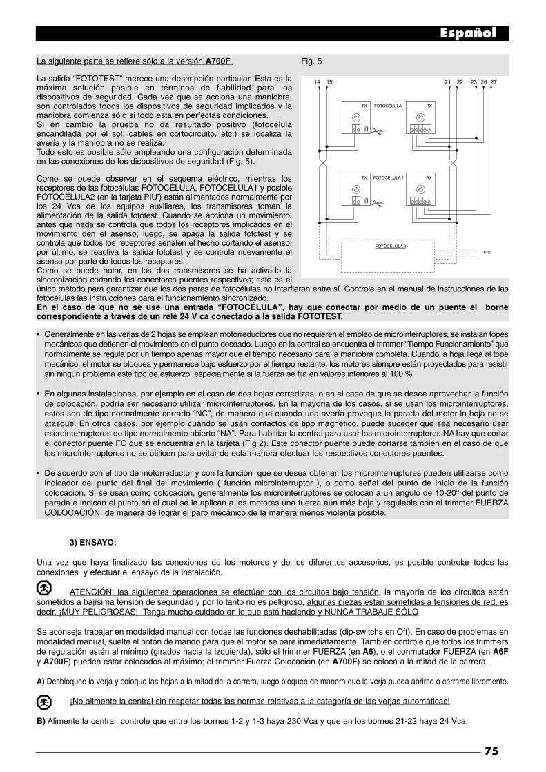
La siguiente parte se refiere sólo a la versión A700F Fig. 5
La salida “FOTOTEST” merece una descripción particular. Esta es lamáxima solución posible en términos de fiabilidad para losdispositivos de seguridad. Cada vez que se acciona una maniobra,son controlados todos los dispositivos de seguridad implicados y lamaniobra comienza sólo si todo está en perfectas condiciones.Si en cambio la prueba no da resultado positivo (fotocélulaencandilada por el sol, cables en cortocircuito, etc.) se localiza laavería y la maniobra no se realiza.Todo esto es posible sólo empleando una configuración determinadaen las conexiones de los dispositivos de seguridad (Fig. 5).
Como se puede observar en el esquema eléctrico, mientras losreceptores de las fotocélulas FOTOCÉLULA, FOTOCÉLULA1 y posibleFOTOCÉLULA2 (en la tarjeta PIU’) están alimentados normalmente porlos 24 Vca de los equipos auxiliares, los transmisores toman laalimentación de la salida fototest. Cuando se acciona un movimiento,antes que nada se controla que todos los receptores implicados en elmovimiento den el asenso; luego, se apaga la salida fototest y secontrola que todos los receptores señalen el hecho cortando el asenso;por último, se reactiva la salida fototest y se controla nuevamente elasenso por parte de todos los receptores.Como se puede notar, en los dos transmisores se ha activado lasincronización cortando los conectores puentes respectivos; este es elúnico método para garantizar que los dos pares de fotocélulas no interfieran entre sí. Controle en el manual de instrucciones de lasfotocélulas las instrucciones para el funcionamiento sincronizado.En el caso de que no se use una entrada “FOTOCÉLULA”, hay que conectar por medio de un puente el bornecorrespondiente a través de un relé 24 V ca conectado a la salida FOTOTEST.
Generalmente en las verjas de 2 hojas se emplean motorreductores que no requieren el empleo de microinterruptores, se instalan topesmecánicos que detienen el movimiento en el punto deseado. Luego en la central se encuentra el trimmer “Tiempo Funcionamiento” quenormalmente se regula por un tiempo apenas mayor que el tiempo necesario para la maniobra completa. Cuando la hoja llega al topemecánico, el motor se bloquea y permanece bajo esfuerzo por el tiempo restante; los motores siempre están proyectados para resistirsin ningún problema este tipo de esfuerzo, especialmente si la fuerza se fija en valores inferiores al 100 %.
En algunas instalaciones, por ejemplo en el caso de dos hojas corredizas, o en el caso de que se desee aprovechar la funciónde colocación, podría ser necesario utilizar microinterruptores. En la mayoría de los casos, si se usan los microinterruptores,estos son de tipo normalmente cerrado “NC”, de manera que cuando una avería provoque la parada del motor la hoja no seatasque. En otros casos, por ejemplo cuando se usan contactos de tipo magnético, puede suceder que sea necesario usarmicrointerruptores de tipo normalmente abierto “NA”. Para habilitar la central para usar los microinterruptores NA hay que cortarel conector puente FC que se encuentra en la tarjeta (Fig 2). Este conector puente puede cortarse también en el caso de quelos microinterruptores no se utilicen para evitar de esta manera efectuar los respectivos conectores puentes.
De acuerdo con el tipo de motorreductor y con la función que se desea obtener, los microinterruptores pueden utilizarse comoindicador del punto del final del movimiento ( función microinterruptor ), o como señal del punto de inicio de la funcióncolocación. Si se usan como colocación, generalmente los microinterruptores se colocan a un ángulo de 10-20° del punto deparada e indican el punto en el cual se le aplican a los motores una fuerza aún más baja y regulable con el trimmer FUERZACOLOCACIÓN, de manera de lograr el paro mecánico de la manera menos violenta posible.
3) ENSAYO:
Una vez que haya finalizado las conexiones de los motores y de los diferentes accesorios, es posible controlar todos lasconexiones y efectuar el ensayo de la instalación.
ATENCIÓN: las siguientes operaciones se efectúan con los circuitos bajo tensión, la mayoría de los circuitos estánsometidos a bajísima tensión de seguridad y por lo tanto no es peligroso, algunas piezas están sometidas a tensiones de red, esdecir, ¡MUY PELIGROSAS! Tenga mucho cuidado en lo que está haciendo y NUNCA TRABAJE SÓLO
Se aconseja trabajar en modalidad manual con todas las funciones deshabilitadas (dip-switchs en Off). En caso de problemas enmodalidad manual, suelte el botón de mando para que el motor se pare inmediatamente. También controle que todos los trimmersde regulación estén al mínimo (girados hacia la izquierda), sólo el trimmer FUERZA (en A6), o el conmutador FUERZA (en A6Fy A700F) pueden estar colocados al máximo; el trimmer Fuerza Colocación (en A700F) se coloca a la mitad de la carrera.
A) Desbloquee la verja y coloque las hojas a la mitad de la carrera, luego bloquee de manera que la verja pueda abrirse o cerrarse libremente.
¡No alimente la central sin respetar todas las normas relativas a la categoría de las verjas automáticas!
B) Alimente la central, controle que entre los bornes 1-2 y 1-3 haya 230 Vca y que en los bornes 21-22 haya 24 Vca.
Español
75
TX FOTOCÉLULA
FOTOCÉLULA 1
FOTOCÉLULA 2PIU'
RX
TX RX
14 21 22 23 26 2715
•
•
•

La siguiente parte se refiere sólo a la versión A700F
C) Controle que en los bornes 14-15 haya una tensión de 24 Vca para la alimentación de los transmisores de las fotocélulas.
Ni bien la central está alimentada, los indicadores luminosos (LED) que se encuentran en las entradas habilitadas tienen queencenderse, además el led “OK” tiene que comenzar a centellear regularmente. Si esto no fuera así, corte inmediatamente laalimentación y controle más atentamente las conexiones.
El led “OK”, que está colocado en el centro de la tarjeta, tiene la función de indicar el estado de la lógica interior: centellearegularmente cada 1 segundo y señala que el microprocesador interior está habilitado y espera el mando. Cuando el mismomicroprocesador reconoce una variación en el estado de una entrada (tanto entrada de mando como dip-switch de las funciones)se produce un centelleo doble rápido, incluso si la variación no provoca efectos inmediatos. Un centelleo rápido 3 veces porsegundo indica que la central ha sido apenas conectada y está efectuando la prueba de las piezas interiores, por último, uncentelleo irregular e inconstante indica que la prueba ha dado resultados negativos y, por cosiguiente, hay una avería.
D) Entonces, controle que los leds que corresponden a las entradas con contactos tipo NC estén encendidos (todos losdispositivos de seguridad accionados) y que los leds que corresponden a las entradas con contactos tipo NA estén apagados(ningún accionamiento habilitado); si ésto no se produce, controle las conexiones y que todos los dispositivos funcionencorrectamente.
E) Controle que todos los dispositivos de seguridad presentes en la instalación funcionen correctamente (parada de emergencia,fotocélulas, bordes neumáticos, etc.); cada vez que se activan, tienen que apagarse los respectivos leds STOP, FOTOCÉLULA,o FOTOCÉLULA2.
Este es uno de los controles más importantes que tiene que efectuar, del funcionamiento correcto de los dispositivos de seguridaddepende toda la seguridad de la máquina verja. Si la luz intermitente es un instrumento ideal para señalar el estado de peligro ylos limitadores de par son un válido auxilio para limitar los daños, sólo una instalación correcta de los dispositivos de seguridadpermite bloquear el automatismo antes que pueda provocar daños.
La siguiente parte se refiere sólo a la versión A700F
F) Si se utilizan las entradas microinterruptor, es necesario controlar que las conexiones sean exactas. Mueva las hojas una porvez y controle que al alcanzar el punto deseado se accione el microinterruptor correspondiente, apagando el respectivo led en lacentral (o encendiéndolo si están instalados los microinterruptores NA).
Entonces, controle si el movimiento se efectúa en la dirección correcta, es decir, controlar que el movimiento previsto por la centraly aquél efectivo de las hojas correspondan. Este control es fundamental; si la dirección es incorrecta, en algunos casos (porejemplo en modalidad semiautomática) la verja aparentemente podría funcionar regularmente; en efecto, el ciclo ABRE esparecido al ciclo CIERRA con una diferencia fundamental: que los dispositivos de seguridad son ignorados en la maniobra decierre, la cual es generalmente más peligrosa, y se accionarán durante la apertura provocando un cierre sobre el obstáculo conresultados desastrosos.
G) Para controlar si el sentido de rotación es correcto, es suficiente dar un impulso en la entrada Paso a Paso; la primeramaniobra que la central efectúa tras haber sido accionada siempre es ABRE, es decir que es suficiente controlar si la verja seabre; por último, si el movimiento se ha efectuado en el sentido incorrecto es necesario:
1 - Apagar la alimentación2 - Cambiar las conexiones “ABRE” y “CIERRA” del motor o de los motores que giraban en el sentido contrario.
Una vez efectuado cuanto indicado, pruebe nuevamente si el sentido de rotación es correcto, repitiendo la operación del punto “G”.
H) Controle todas las conexiones y una vez controlado el sentido de rotación de los motores, pruebe un movimiento completo delos accionadores; se aconseja trabajar siempre en modalidad manual con todas las funciones desactivadas. Si usa como mandola entrada Paso a Paso, el primer movimiento (tras el encendido) tendrá que ser en apertura. Actuando sobre las entradas demando, mueva la verja hasta el punto de apertura; si todo se funciona regularmente, cierre la verja y muévala hasta el punto deparada correspondiente.Conviene efectuar diferentes maniobras abre-cierra para evaluar posibles defectos en la estructura mecánica de laautomatización y detectar la presencia de puntos de fricción particulares.
I) Pruebe ahora el accionamiento de los dispositivos de seguridad: la FOTOCÉLULA y la FOTOCÉLULA1 durante la apertura notienen ningún efecto, durante el cierre detiene el movimiento. Si se encuentra la tarjeta PIU’, pruebe también el funcionamientode la entrada FOTOCÉLULA2, que durante el cierre no tiene ningún efecto, y durante la apertura detiene el movimiento. Losdispositivos conectados a la entrada STOP trabajan tanto durante la apertura como durante el cierre, deteniendo siempre elmovimiento.
Español
76
•
•
•

3.1) REGULACIONES:
✓ Si la verja está compuesta de 2 hojas quese pueden atascar si comienzan a abrirsecontemporáneamente, o si al cerrarse una sesuperpone a la otra, entonces hay que regularlos trimmers Tiempo Retardo Apertura “TRA”o Tiempo Retardo Cierre “TRC”. Dichostrimmers pueden ser regulados a placer,aunque si habitualmente TRA se regula elmínimo indispensable para que la hojamovida por el 2° motor ya esté fuera delespacio ocupado cuando se pone en marchael 1° motor. El trimmer TRC debe ser regulado de manera que durante el cierre la hoja del 2° motor siempre llegue cuando el 1° motor haterminado la maniobra de cierre.
El Tiempo Retardo Cierre puede emplearse para obtener el límite de seguridad durante el cierre de 50 cm previsto porel punto 5.4.2.3. de las normas UNI 8612 edic. 89.
✓ A este punto, seleccione la modalidad de funcionamiento “Semiautomático” desplazando hacia On el dip-switch N°1, entoncesregule el trimmer Tiempo Funcionamiento a la mitad de la carrera aproximadamente. Con estas regulaciones pruebe todo un ciclode apertura y luego uno de cierre, si es necesario, modifique la regulación del trimmer Tiempo Funcionamiento de manera quesea suficiente para desarrollar toda la maniobra y quede un margen de tiempo de 2 ó 3 segundos. Si poniendo el trimmer almáximo no se obtiene un tiempo suficiente, puede cortar el conector puente TLM, que se halla en el circuito impreso cercano altrimmer, y así obtener un tiempo de funcionamiento aumentado.
Las normativas UNI 8612 edic.89 para prevenir el riesgo de aplastamiento, prevén en el punto 6.1.5. entre las medidasposibles, el empleo de limitadores de par que puedan ser regulados de manera que el empuje máximo de la verja medido en elcanto de la hoja no supere los 150 N (~ 15 Kg). En verdad, la norma añade la condición de que la energía cinética de la hoja seainferior a 10 Joule (10 N/m) pero no aclara qué método utilizar en alternativa; de todas maneras es una solución ideal y ¡debe sersiempre aplicada!.
✓ En algunos tipos de accionadores, por ejemplo los de tipo hidráulico, la regulación de la fuerza está prevista directamentesobre el grupo accionador, consúltese el respectivo manual de instrucciones para aclaraciones sobre la regulación; entonces, dejela regulación de la fuerza que está en la central fijada al máximo.Para todos los tipos de accionadores que no contienen un dispositivo de regulación de la fuerza ,es posible aprovechar el sistemade regulación de fuerza que está dentro de la central: según la versión de la central empleada siga las instrucciones respectivas.
La siguiente parte se refiere sólo a la versión A6
En la central hay un trimmer FUERZA que generalmente está fijado para la fuerza máxima, con un destornillador gire el trimmerhacia la izquierda hasta reducir la fuerza del motor al valor previsto por las normativas.
La siguiente parte se refiere sólo a las versiones A6F y A700F
En la central hay un transformador automático de potencia adecuada, con tomas en el devanado primario seleccionablesmediante el conmutador FUERZA. Coloque el conmutador en la posición más adecuada para reducir la fuerza del motor al valorprevisto por las normativas.Cualesquiera que sea el sistema de regulación de la fuerza, para la etapa inicial del movimiento y por una duración de 1,5 Segse da la fuerza máxima, sólo después de este tiempo definido “Punto de arranque” se conecta la fuerza prevista.
✓ Si se selecciona la modalidad de funcionamiento automático (dip-switch N° 2 On) al final de la maniobra de apertura se efectúauna “pausa” después de la cual arranca automáticamente una maniobra de cierre. Este tiempo en el cual la verja queda abierta,puede regularse desde el respectivo trimmer TIEMPO PAUSA que puede fijarse por el tiempo preferido sin ninguna clase delimitación.Un cierre automático y la respectiva pausa se acciona también en el movimiento semiautomático, cuando, durante el cierre, laconexión de un dispositivo de seguridad provoca una inversión del movimiento durante la apertura.
✓ Sólo entonces, al finalizar todas las regulaciones, aconsejamos conectar el radiorreceptor recordando que los mandos queprovienen del mismo se envían a la entrada PASO A PASO.
Español
77
TLM = Tiempo Funcionamiento Aumentado
TL = Tiempo FuncionamientoTP = Tiempo PausaTRA = Tiempo Retardo AperturaTRC = Tiempo Retardo Cierre
F = FuerzaFP = Fuerza Colocación
TLM
TL
F FP
TP TRA TRC

3.2) MODALIDADES DE FUNCIONAMIENTO:
Nota: algunas de las piezas descriptas a continuación se refieren sólo a la versión A700F
En el funcionamiento en modalidad manual, la entrada ABRE permite el movimiento de apertura, la entrada CIERRA permite elmovimiento de cierre. El PASO a PASO permite el movimiento alternativamente de apertura y cierre; apenas cesa el mando deentrada el movimiento se detiene. Durante la apertura el movimiento se para cuando se accionan los microinterruptores de tope,o bien si falta el permiso de la FOTOCÉLULA 2 (en la tarjeta PIU’); en cambio, durante el cierre, el movimiento se para si falta elasenso de FOTOCÉLULA y FOTOCÉLULA 1. El accionamiento de STOP, provoca una parada inmediata del movimiento tantodurante la apertura como durante el cierre. Una vez que el movimiento se ha detenido, deje de accionar el mando en entradaantes de poder iniciar con un nuevo movimiento.
Durante el funcionamiento en una de las dos modalidades automáticas (semiautomático, automático o cierra siempre) un impulsode accionamiento en la entrada ABRE provoca el movimiento de apertura, si el mando prosigue una vez que se produce laapertura el movimiento queda “congelado” en una pausa infinita; sólo cuando cesa el mando, la verja podrá cerrarse nuevamente.Un impulso en PASO a PASO provoca alternativamente la apertura, o el cierre. Un segundo impulso sobre PASO a PASO, o enla misma entrada que ha comenzado el movimiento, provoca un Stop.El accionamiento de STOP provoca una parada inmediata del movimiento, tanto durante la apertura como durante el cierre.
Si en una entrada de mando en vez de un impulso se mantiene una señal continua, se provoca un estado de “preponderancia”en el cual las demás entradas quedan deshabilitadas (útil para conectar un reloj o un selector Noche-Día).
En el caso de que se seleccione la modalidad de funcionamiento automática, tras una maniobra de apertura, se efectúa unapausa y luego el cierre. Si durante la pausa se acciona FOTOCÉLULA o FOTOCÉLULA1, el temporizador se restablecerá conun nuevo tiempo de pausa; si en cambio durante la pausa se acciona STOP, la función de cierre se pone en cero y se pasa a unestado de STOP.
Durante la apertura, el accionamiento de la FOTOCÉLULA o FOTOCÉLULA1 no tienen ningún efecto, mientras que laFOTOCÉLULA2 (en la tarjeta PIU’) provoca la inversión del movimiento; durante el cierre, el accionamiento de la FOTOCÉLULAo FOTOCÉLULA1 provoca una inversión del movimiento, luego una nueva pausa y finalmente un nuevo cierre.
4) PROGRAMACIÓN:
La central dispone de una serie de microinterruptores que permiten accionar varias funciones para que la instalación sea másadecuada a la exigencias del usuario y más segura bajo las diversas condiciones de empleo. Todas las funciones se accionanponiendo el respectivo dip-switch en la posición “On”, mientras que con el dip-switch correspondiente en “Off” no estánintroducidas; algunas funciones no tienen un efecto inmediato y tienen sentido sólo bajo determinadas condiciones, por ejemplola función N° 12 “Intermitente también en pausa” se acciona sólo con cierre automático y si la maniobra no es interrumpida porun mando de STOP.
ATENCIÓN algunas de las funciones programables están vinculadas con aspectos de la seguridad, evalúe con muchaatención los efectos de una función y verifique cuál es la función que da la mayor seguridad posible.En el mantenimiento de una instalación, antes de modificar una función programable, evalúe el motivo por el cual durante lainstalación se habían tomado ciertas decisiones, y controle si la seguridad se verá perjudicada por la nueva programación.
4.1) FUNCIONES PROGRAMABLES:
El dip-switch FUNCIONES permite seleccionar las diversas modalidades de funcionamiento e introducir las funciones deseadassegún la tabla siguiente:
Switch 1-2: Off Off = Movimiento “Manual”, es decir Pulsador de interrupción automáticaOn Off = Movimiento “Semiautomático”Off On = Movimiento “Automático”, es decir Cierre Automático On On = Movimiento “Automático + Cierra siempre”
Switch 3 On = Funcionamiento en común <No disponible en modalidad Manual>Switch 4 On = Centelleo previoSwitch 5 On = Cierra inmediatamente después de Fotocélula <sólo en modalidad Automática>Switch 6 On = Fotocélula1 también durante aperturaSwitch 7 On = Puesta en marcha gradualSwitch 8 On = Parada gradualSwitch 9 On = Golpe de arieteSwitch 10 On = Luz de cortesía en intermitente
Español
78

En la versión A700F hay un segundo grupo de dip-switches con otras funciones:
Switch 11 On = Función colocación < sólo con empleo de los microinterruptores >Switch 12 On = Luz intermitente también en Pausa <sólo en modalidad Automática> Switch 13 On = Mantenimiento presiónSwitch 14 On = Indicador luminoso verja abierta con luz intermitente proporcionalSwitch 15 On = Activación FototestSwitch 16 On = Fotocélula y Fotocélula1 también en aperturaSwitch 17 On = Fotocélula y Fotocélula1 al inicio de la maniobra de aperturaSwitch 18 On = Salta STOP durante apertura Switch 19 On = Salta STOP durante cierreSwitch 20 On = CIERRA se convierte en ABRE PEATONAL
• Recordamos que las funciones que pueden ejecutarse sólo en ciertos casos están evidenciadas con las notas entre caracteres“<>” después de la descripción de la función.
• Obviamente, cada dip-switch que está en “Off” no activa la función descripta.
4.2) DESCRIPCIÓN DE LAS FUNCIONES:
A continuación mencionamos brevemente las funciones que se pueden introducir colocando en “On” el respectivo dip-switch.
Switch 1-2: Off Off = “Movimiento “Manual”, (Pulsador de interrupción automática)On Off = Movimiento “Semiautomático”Off On = Movimiento “Automático” (Cierre Automático)On On = Movimiento “Automático + Cierra siempre”
Durante el funcionamiento “Manual”, el movimiento se efectúa sólo hasta que se acciona el mando (botón apretado).En modalidad “Semiautomática”, es suficiente dar un impulso de mando para que se cumpla todo el movimiento, hasta alcanzarel tope mecánico o hasta que interviene el microinterruptor de tope. En la modalidad de funcionamiento “Automática”, despuésde la apertura, se efectúa una pausa y luego un cierre.La función “Cierre Siempre” se acciona tras un corte momentáneo de alimentación, si detecta que la verja está abierta, se poneen marcha automáticamente una maniobra de cierre, antecedida por 5 segundos de centelleo previo.
Switch 3: On = Funcionamiento en común (no disponible en modalidad Manual)
Durante el funcionamiento en común, una vez que se puso en marcha un movimiento de apertura, éste no puede ser interrumpidopor otros impulsos de mando en PASO A PASO O ABRE, hasta que no finalice el movimiento de apertura.Durante el movimiento de cierre, al efectuar un nuevo accionamiento, se produce la parada y la inversión automática delmovimiento y se abre nuevamente.
Switch 4: On = Centelleo previo
Al recibir el impulso de mando, se activa la luz intermitente, luego de 5 segundos (2 seg. si está en modalidad manual) inicia elmovimiento.
Switch 5: On = Cierra inmediatamente después de Fotocélula (sólo si está en modalidad automática)
Esta función permite mantener la verja abierta sólo por el tiempo necesario para el tránsito; en efecto, el cierre automático seproducirá tras 5 segundos de la activación de la Fotocélula o Fotocélula1, independientemente del Tiempo Pausa programado.
Switch 6: On = Fotocélula1 también durante apertura
Esta función es la única que diferencia el funcionamiento entre las fotocélulas FOTOCÉLULA y FOTOCÉLULA1. Normalmente,los dispositivos de seguridad FOTOCÉLULA y FOTOCÉLULA1 se accionan sólo durante la maniobra de cierre, y no tienen ningúnefecto durante la apertura.Si se coloca el dip-switch N° 6 en “On”, FOTOCÉLULA sigue accionándose sólo durante la maniobra de cierre, peroFOTOCÉLULA1 se acciona también durante la apertura, interrumpiendo el movimiento. En semiautomático o automático elmovimiento recomienza cuando FOTOCÉLULA1 se vuelva a desacoplar.Este tipo de funcionamiento es útil para detener el movimiento de la verja durante la apertura, cuando, por ejemplo, un vehículose acerca a la verja desde el lado interno, es decir desde la dirección del movimiento, sin por ello detener el movimiento cuandoel vehículo se acerca desde el lado externo.
Switch 7: On = Puesta en marcha gradual
El movimiento comienza de manera gradual, enviando una fuerza siempre mayor al motor, formando una rampa que dura 1 seg.,lo cual garantiza que se ponga en marcha sin sacudidas. (No aconsejado con los motorreductores METRO).
Español
79

Switch 8: On = Parada gradual
Cuando el movimiento termina se detiene gradualmente, enviando una fuerza siempre menor al motor, con un decremento quedura 1 Seg. aproximadamente, lo cual garantiza que se pare sin sacudidas.Por motivos de seguridad evidentes, la parada gradual no se produce, y es sustituida por una parada normal, cuando se accionanSTOP, FOTOCÉLULA y FOTOCÉLULA1 o FOTOCÉLULA2 (en la tarjeta PIU’) o bien uno de los microinterruptores.
Switch 9: On = Golpe de ariete
Cuando se emplean accionadores reversibles, es decir que la verja no queda cerrada sólo con el empuje de los motores, esindispensable instalar una electrocerradura (véanse las instrucciones de los accionadores para el modo de empleo).En la electrocerradura se podría encontrar aplicado ese empuje natural que tiende a llevar las hojas a una posición ligeramenteabierta, y ciertas veces ese empuje es tan elevado que mantiene bloqueado el mecanismo de disparo de la electrocerradura. Con la función de golpe de ariete conectada, antes de comenzar una maniobra de apertura se activa un ciclo de cierre breve, quede todas maneras no provoca ningún efecto de movimiento, visto que las hojas ya están en el tope mecánico de cierre. De talmanera, cuando la electrocerradura se acciona se encontrará descargada de toda fuerza y libre de desengancharse.
Switch 10: On = Luz de cortesía en la luz intermitente
En ciertos casos, puede ser necesaria una iluminación de la zona de movimiento de la verja y, a menudo, se requiere que lailuminación se apague automáticamente poco después de que la verja se ha detenido. Esta función comúnmente se define “Luzde cortesía”. Conectando elementos de iluminación adecuados en la misma salida de la luz intermitente (para una potencia totalmáxima de 100 W) y accionando esta función se obtendrá que durante todo el movimiento y por 60 Seg. más, la salidapermanezca activa permitiendo la iluminación de la zona.
Sólo en la versión A700F hay un segundo grupo de dip-switches con otras funciones:
Switch 11 On = Función colocación (sólo con empleo de los microinterruptores)
Los microinterruptores en lugar de emplearse como señal de los límites del movimiento, pueden usarse como indicación del puntoen el cual se acciona la colocación. Generalmente, cuando se usa la función colocación los microinterruptores se colocan en unángulo de 10-20° antes del tope mecánico. De esta manera, cuando en el movimiento de la hoja se alcanza el microinterruptor,se enviará al motor una fuerza menor, regulable con el respectivo trimmer “Fuerza Colocación”, por un tiempo de otros 3 Seg. demanera que la hoja alcanceel tope mecánico con la menor violencia posible.
Switch 12 On = Luz intermitente también en Pausa
Normalmente, la luz intermitente se acciona sólo durante el movimiento de apertura o cierre; esta función prevé que la luzintermitente permanezca accionada incluso durante la Pausa, con el fin de señalar el estado de “cierre próximo”.
Switch 13 On = Mantenimiento presión
En los accionadores hidráulicos, el empuje para mantener cerrada la verja se desarrolla en el circuito hidráulico que quedasiempre bajo presión. Cuando el tiempo y el desgaste reducen la hermeticidad del circuito hidráulico, puede suceder que trasalgunas horas la presión interior baje con el riesgo consiguiente de una apertura ligera de las hojas de la verja.Si se introduce la función Mantenimiento Presión, tras 4 horas, y luego cada 4 horas mientras la verja esté cerrada, se activa unabreve maniobra de cierre con la única finalidad de recargar la presión del circuito hidráulico.NOTA: Las funciones “Golpe de ariete” y “Mantenimiento Presión” tienen sentido y se llevan a cabo sólo si la verja está cerrada.La lógica interna considera verja cerrada si el respectivo microinterruptor FCC se ha accionado o, en el caso de que no se usenlos microinterruptores, del hecho que la maniobra anterior de cierre haya terminado por fin del tiempo de funcionamiento
Switch 14 On = Indicador luminoso Verja Abierta con luz intermitente proporcional
Normalmente, la Luz Indicadora de Verja Abierta indica el estado de la verja según los siguientes estados:
Apagado : Verja completamente cerradaEncendido : Verja también abierta sólo parcialmenteCentelleo lento : Verja durante aperturaCentelleo veloz : Verja durante cierre
El centelleo del indicador durante el movimiento puede hacerse proporcional, desde lento progresivamente a rápido y viceversa,para tener una indicación del estado de apertura o cierre.
Switch 15 On = Activación Fototest
Permite efectuar una prueba de las fotocélulas , antes de comenzar cada movimiento, de esta manera, eliminando todaposibilidad de funcionamiento defectuoso, se aumenta la seguridad de la instalación. Para aprovechar la función Fototest, lostransmisores de las fotocélulas tienen que estar conectados a la respectiva salida (véanse: Notas de las conexiones).
Español
80

Switch 16 On = Fotocélula y Fotocélula1 también durante apertura
Normalmente, los dispositivos de seguridad FOTOCÉLULA y FOTOCÉLULA1 se accionan sólo durante la maniobra de cierre, sise activa el dip-switch N° 16 se accionan los dispositivos de seguridad que interrumpen el movimiento también durante laapertura, si está en semiautomático o automático el movimiento de apertura recomienza inmediatamente después deldesacoplamiento .
Switch 17 On = Fotocélula y Fotocélula1 al inicio de la maniobra de apertura
Habitualmente, los dispositivos de seguridad FOTOCÉLULA y FOTOCÉLULA1 no están accionados en la maniobra de apertura,sino sólo en la de cierre porque es la más peligrosa. En algunos países hay normativas que imponen el control de los dispositivosde seguridad por lo menos al inicio de la maniobra de apertura. Si es necesario respetar tales normas, o si se desea aumentarel nivel de seguridad, puede accionar la función, entonces, antes de iniciar el movimiento, se verifica el asenso de los dispositivosde seguridad FOTOCÉLULA y FOTOCÉLULA1 y sólo después inicia el movimiento.
Switch 18 On = Salta STOP durante apertura
El ciclo de Paso a Paso es normalmente: ABRE-STOP-CIERRA-STOP, con esta función introducida el ciclo Paso a Paso setransforma en: ABRE-CIERRA-STOP-ABRE, mientras que la entrada Abre pierde la posibilidad de hacer STOP
Switch 19 On = Salta STOP durante cierre
Es como la función anterior pero se refiere al ciclo de cierre, de consecuencia el ciclo Paso a Paso se transforma en: ABRE-STOP-CIERRA- ABRE , mientras que la entrada Cierra pierde la posibilidad de hacer STOPNOTA: Colocando los dip-switches 18 y 19 en On, el ciclo paso a paso se transforma en ABRE-CIERRA-ABRE perdiendodefinitivamente la posibilidad de hacer STOP.
Switch 20 On = CIERRA se convierte en ABRE PEATONAL
Puede suceder que no sea necesario abrir completamente la verja, por ejemplo cuando debe pasar un peatón, en dicho caso esútil la función ABRE PEATONAL que permite abrir sólo la hoja conectada al 2° motor dejando la otra cerrada. Este tipo deapertura se activa desde la entrada CIERRA, que pierde su función original para volverse como la entrada Paso a Paso, peropara la apertura de una sola hoja. Hay que precisar que el ciclo de abre peatonal se acciona sólo con la verja cerrada, en cambiosi la verja está en movimiento, o abierta, el impulso de entrada no tiene ningún efecto.
ACCESORIO : TARJETA DE EXPANSIONES “ PIU’”
La central electrónica dispone de todas las funciones principales requeridas por una automatización normal, en la versión A700Fexiste la posibilidad de agregar la tarjeta opcional PIU’, que permite aumentar los servicios de la central.
La siguiente parte se refiere sólo a la versión A700F
La tarjeta se enchufa en el respectivo conector en la central, en los bornes de la tarjeta se dispone de :
• Las siguientes entradas:
Foto 2 = Dispositivo de seguridad con accionamiento de la maniobra de aperturaAbre Parcial = efectúa una maniobra de apertura con un tiempo reducido
• Las siguientes salidas:
Rojo = Luz roja del semáforo \Verde = Luz verde del semáforo | AlarmasElectrocerradura = Accionamiento de la electrocerradura (dado que la central ya dispone de esta salida la función ha
sido modificada en “Ventosa” para conectar los dispositivos de retención magnética que se usan comoalternativa a la electrocerradura )
Luz de Cortesía = Accionamiento de una lámpara con función de luz de cortesía
Nota: Las salidas pueden accionar sólo cargas de potencia pequeña (luces indicadoras, relés, etc.)
• y las siguientes regulaciones:Tiempo Parcial = Tiempo para la apertura parcialTiempo Cortesía = Tiempo para la luz de cortesía
Las características completas y el modo de empleo de la tarjeta se encuentran en el respectivo manual de instrucciones.
Español
81
CARACTERÍSTICAS TÉCNICAS DE LA CENTRAL:
Alimentación : 230 Vca ± 20%, 50 HzPotencia máxima accionadores : dos motores de 1/2 Hp con condensador máximo de 20 µFPotencia máxima luz intermitente : 100 W a 230 Vca ( la salida tiene tensión fija.)
Corriente Máx equipos auxiliares 24 Vca : 200 mACorriente Máx salida fototest : 100 mAPotencia máxima indicador luminoso Verja Abierta: 2 W (24 Vca)Potencia máxima electrocerradura : 25 W (12 Vca)Tiempo de funcionamiento : de 2,5 a 40 Seg. (de 30 a 80 Seg. con TLM)Tiempo pausa : de 5 a 80 Seg.Tiempo retardo ritaritardorirdo apertura TRA : 0 o bien de 2.5 a 12 Seg. (retardo puesta en marcha 1° motor durante apertura)Tiempo retardo cierre TRC : 0 o bien de 2.5 a 12 Seg. (retardo puesta en marcha 2° motor durante cierre)Regulación fuerza : de 0 al 100% en la versión A6; 30-45-60-80-100% en las versiones A6F y A700FTemperatura de servicio : -20 ÷ 70 °C
Dimensiones : 280 x 220 x 110Peso : 2,7 Kg aprox.Grado de protección : IP 55
Nice s.r.l. se reserva el derecho de modificar sus propios productos en cualquier momento sin previo aviso.
Español
82
NOTAS FINALES:
El presente manual está destinado sólo al personal técnico cualificado para la instalación.
• ¡Ninguna información incluida en el presente manual puede ser de interés para el usuario final!
• ¡El usuario final no puede efectuar ningún ajuste o regulación contenida en el presente manual!
✓ Una vez concluida la instalación, informe al usuario final de manera minuciosa, incluso por escrito, acerca del modo deempleo de la verja automática, los peligros residuales,y la forma de desbloqueo manual en caso de falta de electricidad.
✓ Informe al dueño de la instalación acerca de la necesidad de un buen y constante mantenimiento, en particular sobre lanecesidad de controlar periódicamente los dispositivos de seguridad y los limitadores de par.

83

cart
a ric
icla
ta 1
00%
recy
cled
pap
er 1
00%
papi
er r
ecyc
le 1
00%
100%
Altp
apie
r10
0% p
apel
rec
icla
do
A termine di legge ci riserviamo la proprietà di questo manuale con divieto di riprodurlo o di renderlo comunque noto a terzi o a ditte concorrenti senza nostra autorizzazione.
Istruzioni per il montaggio della centrale MINDY. Instructions for assembly of the MINDY control unit.Instructions pour le montage de l’unité MINDY. Anweisungen für die Montage der Steuerzentrale MINDY.Instrucciones para el montaje de la central MINDY.
I GB
F D
E
Inserire le due viti negli appositi fori superiori facendole scorrere sulla guida,come fig. A avvitandole parzialmente. Ruotare di 180° la centrale e ripetere lastessa operazione con le altre 2 viti.Fissare a parete la centrale.
Insert the two screws in the upper holes provided, sliding them on the guide asin fig. A and partly screwing them in. Turn the control unit through 180° andperform the same operation with the other 2 screws.Fix the control unit on to the wall.
Introduire les deux vis dans les trous supérieurs en les faisant coulisser sur laglissière, comme l’indique la Fig. A, en les vissant partiellement. Tourner l’unitésur 180° et répêter mème opération avec les 2 aufres vis.Fixer l’unité au mur.
Die zwei Schrauben in ihre obenen Löcher einfügen und wie in Abb. A gezeigtauf der Führung gleiten lassen, dann teilweise anschrauben. Die Zentrale um180° drehen und das gleiche mit den zwei anderen Schrauben ausführen.Die Zentrale an der Wand befestigen.
Introduzca los dos tornillos en los respactivos agujeros superiores haciéndolosdeslizar sobre la guia como muestra la Fig. A, atornillándolos parcialmente,gire 180° la central y repita la misma operación con los otros dos tornillos.Fije la central a la pared.
Inserire il coperchio dalla parte desiderata (con apertura a destra o sinistra), premere con forza incorrispondenza delle frecce.
Fix the cover on the desiderd part (with opening on the right or left), press firmly on thearrows.
Placer le couvercle dans la position voulue (avec l’ouverture à droite ou à gauche), appuyerfortement au niveau des flèches.
Den Deckel wie gewünscht aufsetzen (mit Rechts-oder Linksöffnung). Kräftig drücken, wodie Pfeile vorhanden sind.
Introduzca la tapa en la parte deseada (con apertura a derecha o izquierda), apriete con fuerza encorrespondencia de las flechas.
Per togliere il coperchio premere con un cacciavite sul punto di incastro econtemporaneamente spingere verso l’alto.
To remove the cover, press with a screwdriver on the join and push upwards at the same time.
Pour enlever le couvercle, appuyer avec un tournevis sur le point d’encastrement et en mêmetemps pousser vers le haut.
Zum Abnehmen des Deckels mit einem Schraubenzieherauf den Einspannpunkt A drücken undgleichzeitig nach oben schieben.
Para quitar la tapa apriete con un destornillador en el punto de encastre ycontemporáneamente empuje hacla arriba.
I
GB
F
D
E
I
GB
F
D
E
I
GB
F
D
E
A
B
C
D
Nice SpA, Oderzo TV ItaliaVia Pezza Alta, 13 Z. I. RustignèTel. +39.0422.85.38.38 Fax +39.0422.85.35.85
E-mail [email protected] site http://www.niceforyou.com
Nice France, BuchelayTel. +33.(0)1.30.33.95.95Fax +33 (0)1.30.33.95.96
Nice Polska, PruszkówTel. +48.22.728.33.22Fax +48.22.728.25.10
ISTA
6 48
58