Victor Gioncu_ Federico m Mazzolani-ductility Resistant Steel Structures

Sezione STRUTTURE E AMBIENTE Structures and Environment Update: October 2017

S&A – Permanent staff
Giovanni di Luzio Associate Professor
Patrick Bamonte Assistant Professor
Giacomo Boffi Assistant Profesor
Gabriele della Vecchia Associate Professor
Claudio di Prisco Professor
Marco di Prisco Professor
Roberto Felicetti Associate Professor
Matteo Colombo Assistant Professor
Liberato Ferrara Associate Professor

S&A – Permanent staff
Roberto Paolucci Professor
Cristina Jommi Professor
Luca Martinelli Associate Professor
Paolo Martinelli Assistant Professor
Federico Perotti Professor
Lorenza Petrini Associate Professor
Donatella Sterpi Assistant Professor
Maria Gabriella Mulas Associate Professor
Andrea Galli Assistant Professor

S&A – research areas
Concrete and advanced cement based materials (ACBM) and structures
- Concept, development, mechanical characterization and modelling of advanced cement based materials
- Structural behaviour of concrete and ACBM elements
- Innovative structure concept for accidental events and sustainability
- Structural assessment and retrofitting
Earthquake engineering and structural dynamics
- Engineering seismology
- Earthquake engineering
- Structural Dynamics and Wind Engineering
Geomechanics and geotechnical engineering
- Natural hazards: prediction, prevention and mitigation
- Geotechnical structures
- Geo-resources, environment and underground engineering

Concrete and Advanced Cement Based Materials
Mechanical characterization of FRC,HPFRCC, TRC
0.6 3
crack opening w (mm)
0
4
8
12
16
(
N/m
m2)
0 3 6 9
beams L1/2
slab A
DEWS L1/2-B
DEWS T1/2-B
bea
m T
2
bea
m T
150 150150150 500
beam L2
beam L1
150
150
150
50
casting
direction
supposed flow lines
T1-BT2-B
T1-AT2-A L1-A
L2-AL2-B
L1-B
Slab A
0 0.002 0.004 0.006 0.008 0.01
strain
0
4
8
12
16
(
N/m
m2)
beams L1/2
slab A
arctg Ec
DEWS L1/2-B
DEWS T1/2-B
500 mm - 20 in.
150 mm - 6 in.
450 mm - 18 in.
200 mm - 8 in.
A
A sect. A-A
150 mm
6 in.
30 mm - 1.2 in7 mm
0 2 4 6
COD (mm)
0
2
4
6
8
10
(
N/m
m2)
DEWS L1/2-B
DEWS T1/T2-B
DEWS T1/T2-A
DEWS L1/L2-A
Slab A
500 mm - 20 in.
150 mm - 6 in.
450 mm - 18 in.
200 mm - 8 in.
A
A sect. A-A
150 mm
6 in.
30 mm - 1.2 in7 mm

Concrete and Advanced Cement Based Materials
Concept and mechanical characterization of collapsible concrete

Concrete and Advanced Cement Based Materials
Rheological characterization of HPFRCC
Electroacoustical Unit
for in situ measure-
ment of zeta potential
and particle
agglomeration
cement paste or
mortar (dmax < 4 mm)
paddel-shaped rotor
specimen container with anti-wallslip serration
10 mm
50 mm
10 mm
Rheological Building Materials Cell
Rheological Unit

Concrete and Advanced Cement Based Materials
Early age and long term behaviour of concrete
0 100 200 300Time [days]
0.0x100
4.0x10⁻⁴
8.0x10⁻⁴
1.2x10⁻³
1.6x10⁻³
Str
ain
Basic Creep - 2 days
Exp: A5+A6
Exp: A1+A2
B3 model(*)
Exp: manual meas.
(*) Il modello B3 è stato calibrato sulla base delle risultanze sperimentali
1 10 100Time [days]
0.0x100
4.0x10⁻⁴
8.0x10⁻⁴
1.2x10⁻³
1.6x10⁻³
Str
ain
Basic Creep - 2 days
Exp: A5+A6
Exp: A1+A2
B3 model(*)
Exp: manual meas.
(*) Il modello B3 è stato calibrato sulla base delle risultanze sperimentali
0 100 200 300Time [days]
0.0x100
2.0x10⁻⁴
4.0x10⁻⁴
6.0x10⁻⁴
8.0x10⁻⁴
Str
ain
Shrinkage - 28 days
B3 model shrinkage(*)
Exp: manual meas. (shrink.)
10 100Time [days]
0.0x100
2.0x10⁻⁴
4.0x10⁻⁴
6.0x10⁻⁴
8.0x10⁻⁴
Str
ain
Shrinkage - 28 days
B3 model shrinkage(*)
Exp: manual meas. (shrink.)

Concrete and Advanced Cement Based Materials
experimental characterization of HP concrete at high temperature and in residual conditions
0.00 0.05 0.10w (mm)0
1
2
3
4
(MPa)20°C
600°C
250°C fc20
= 90 MPa
residual tests
direct-tension tests
at high temperature
splitting test
under sustained pore pressure
Concrete and Advanced Cement Based Materials
characterization of thermal properties and fire testing of small structures and protective materials
small furnace (BBQ) for fire testing
of panels and protective materials
assessment of thermal diffusivity in the range 20-1000°C
11 Alkali Silica Reaction / GDL
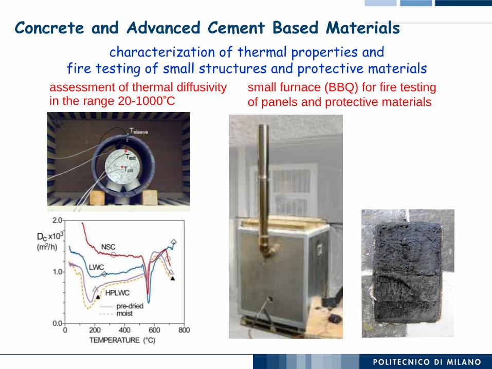
Concrete and Advanced Cement Based Materials
Self healing of cementitious composites
after 1 month in water
after 3 months in water
after 6 months in water

Concrete and Advanced Cement Based Materials
Concept and mechanical characterization of cementitious composites reinforced with natural/recycled fibers
Natural Fibers Absorb the humidity In case of crack the released humidity
will help further hydration
Before
After 1
Month

13 Alkali Silica Reaction / GDL
Concrete and Advanced Cement Based Materials
Damage modelling of concrete behaviour
… vs. DIC

Formation and expansion of ASR gel
14
Development of cracking
Free Expansion Unrest.-20 MPa Rest.-5 mm; 0 MPa
Alkali Silica Reaction / GDL
Meso-scale modeling of Alkali-Silica-Reaction (ASR) damege in concrete
Concrete and Advanced Cement Based Materials

15 Alkali Silica Reaction / GDL
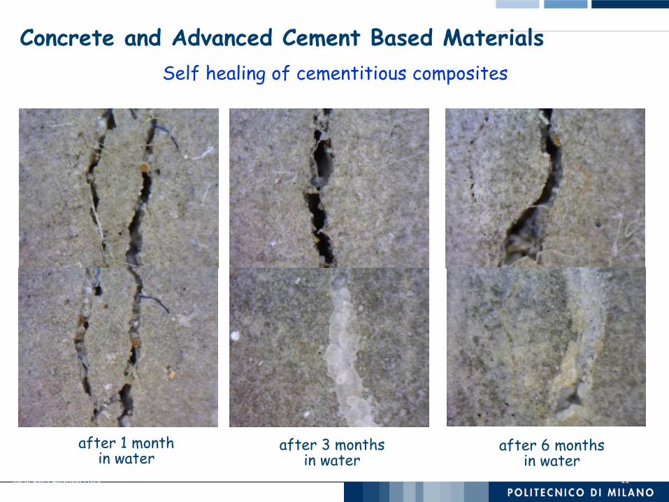
Concrete and Advanced Cement Based Materials … and Structures
development of equipment and setups for material and structural testing (in lab & onsite)
in situ load tests laboratory load tests
fire testing structural monitoring

Advanced Cementitious Composites In
DEsign and coNstruction of safe Tunnels
Advanced Solutions for Outdoor Energetic Retrofit of façade
Concrete and Advanced Cement Based Materials … and Structures
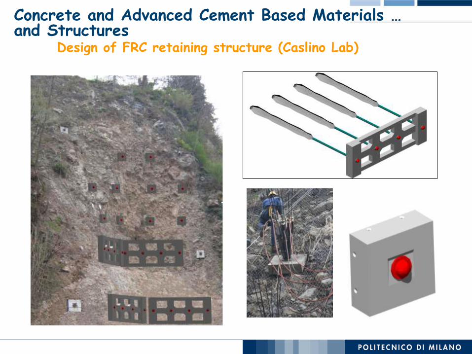
Design of FRC retaining structure (Caslino Lab)
Concrete and Advanced Cement Based Materials … and Structures
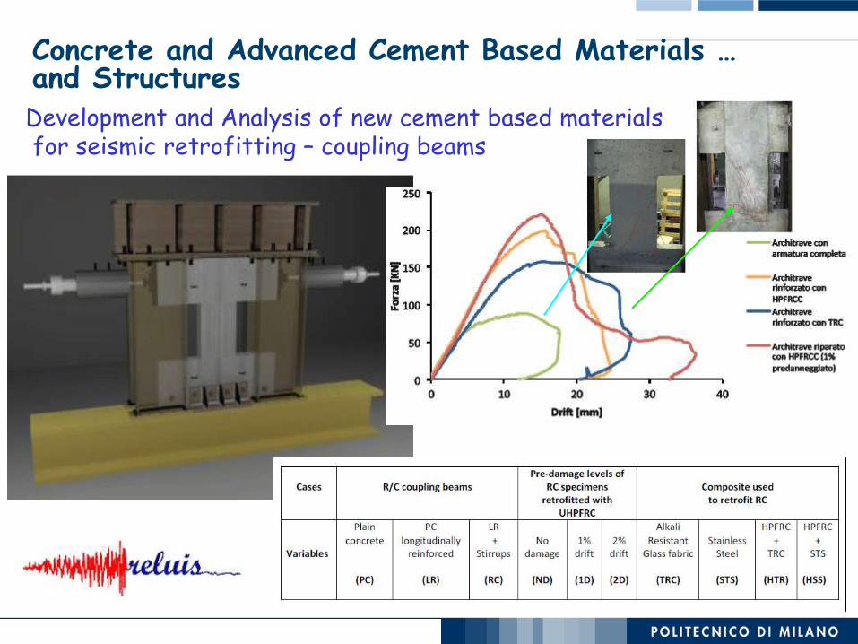
Concrete and Advanced Cement Based Materials … and Structures Development and Analysis of new cement based materials for seismic retrofitting – coupling beams

development of Non-Destructive tools for structural inspection and damage assessment
time of flight of the drill pulses
concrete analysis (colour, carbonation, DTA) via a sorted sample of drilling powder
Concrete and Advanced Cement Based Materials … and Structures

onsite assessment of damaged structures
delamination in floorings and tiles fire damage assessment
debris inspection modelling of fire scenario load/vibration tests residual deformation ultrasonic pulse transmission/refraction drilling resistance rebound hammer pull-out rebars hardness discoloration, chemo-physical analysis
mobile robots for flatness and delamination survey
Concrete and Advanced Cement Based Materials … and Structures

Earthquake engineering and structural dynamics
Seismic Hazard Assessment for critical facilities
Approaches to account for site effects in the Probabilistic Seismic Hazard
Assessment

Earthquake engineering and structural dynamics
High-performance computing tools in elasto-dynamics (SPEED code, with Dept of Mathematics)
Traffic-induced vibrations
Seismic wave propagation in complex geological configurations
L’Aquila basin

Earthquake engineering and structural dynamics
Earthquake ground-shaking scenarios in large urban areas
~ 5 hours on FERMI using 512 cores
SANTIAGO DEL CILE

Earthquake engineering and structural dynamics
Guidelines for gas pipeline design
expected earthquake induced slope displacements
pipeline response under dynamic and fault-rupture loading
seismic hazard assessment

Earthquake engineering and structural dynamics
Software for the design spectrum-compatible selection of real accelerograms (in cooperation with Università Federico II, Napoli)
The project DPC-RELUIS

Earthquake engineering and structural dynamics
The project DPC-RELUIS
Integrated seismic design and assessment of foundations and structures
Experimental results

Earthquake engineering and structural dynamics
The Submerged Floating Tunnel, also known as Archimedes Bridge,
serves as a promising alternative to cross sea-straits, lakes
and waterways in general.
Submerged Floating Tunnels (SFTs)
Engineering solutions
Bridge Underground tunnel Immersed tunnel (I.T.) Floating tunnel (Archimede’s Bridge, SFT “Submerged Floating Tunnel”)
Shallow water ▪
Intermediate depth water
Deep water ▪
Crossing problems:
Conventional tunnel
Immersed tunnel
SFT

Submerged Floating Tunnels
sqsqsq sq sq
eqeqeqeq
one section of tunnel
bars
ISSUES
• Safety assessment (e.g. flooding, fire)
• Soil-structure interaction
• Mooring system: slender members with material and geometric nonlinearity
• 3D multiple-support seismic excitation (eq)
• Seaquake: hydrodynamic pressure on the tunnel (sq)
• Control devices (at tunnel ends and in the mooring system)
Earthquake engineering and structural dynamics

Earthquake engineering and structural dynamics
Structural control of long and medium-span bridges
70 80 90 100 110 120-1
-0.5
0
0.5
1Uy (Gbz)
[s]
[m]
Damping devices
Motion reduction
Medium-span bridge
Earthquake engineering and structural dynamics
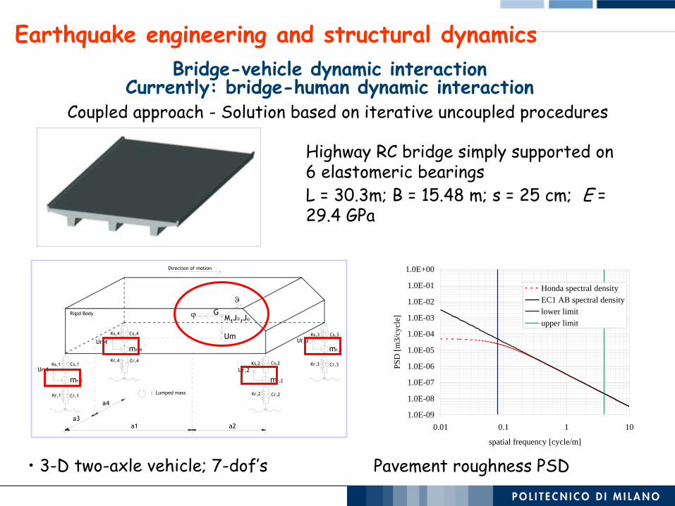
Highway RC bridge simply supported on 6 elastomeric bearings
L = 30.3m; B = 15.48 m; s = 25 cm; E = 29.4 GPa
Bridge-vehicle dynamic interaction Currently: bridge-human dynamic interaction
a1 a2a3
a4
: Lumped mass
Direction of motion
Rigid Body
Ur,1
Ur,4
Ur,2
Ur,3
G
mr,1
mr,4
mr,2
mr,3
Um
M,J,J
Kr,2
Ks,2
Cr,2
Cs,2 Kr,3
Ks,3
Cr,3
Cs,3
Kr,1
Ks,1
Cr,1
Cs,1Kr,4
Ks,4
Cr,4
Cs,4
• 3-D two-axle vehicle; 7-dof’s
1.0E-09
1.0E-08
1.0E-07
1.0E-06
1.0E-05
1.0E-04
1.0E-03
1.0E-02
1.0E-01
1.0E+00
0.01 0.1 1 10
spatial frequency [cycle/m]
PS
D [
m3
/cy
cle]
Honda spectral density
EC1 AB spectral density
lower limit
upper limit
Pavement roughness PSD
Coupled approach - Solution based on iterative uncoupled procedures
Earthquake engineering and structural dynamics
Col_Solid_1.25
-200
-150
-100
-50
0
50
100
150
200
-4 -3 -2 -1 0 1 2 3 4
Deflection [mm]
Late
ral
Fo
rce [
kN
]
Experiment
Flexure model
Col_Solid_1.25
-200
-150
-100
-50
0
50
100
150
200
-4 -3 -2 -1 0 1 2 3 4
Deflection [mm]
Late
ral
Fo
rce [
kN
]
Experiment
Shear model
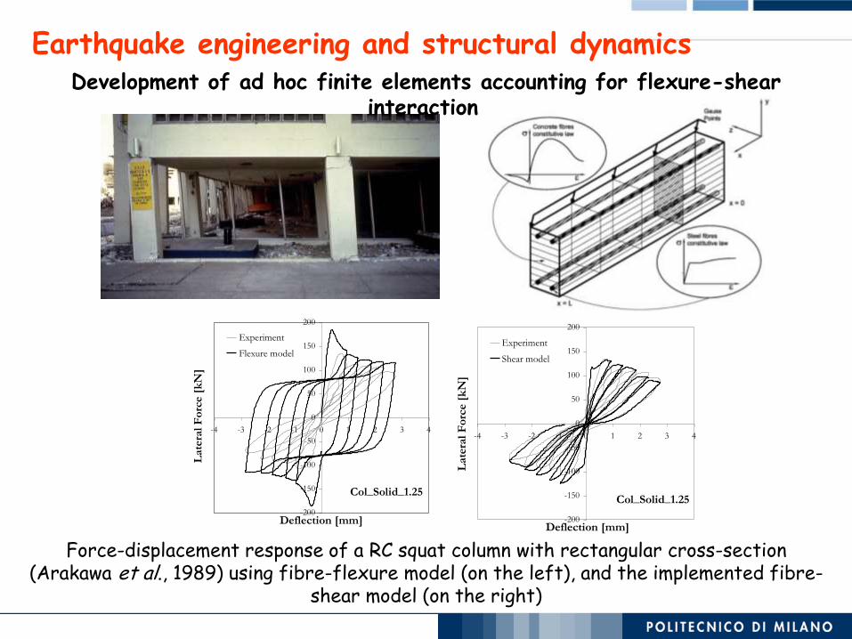
Development of ad hoc finite elements accounting for flexure-shear interaction
Force-displacement response of a RC squat column with rectangular cross-section (Arakawa et al., 1989) using fibre-flexure model (on the left), and the implemented fibre-
shear model (on the right)

Earthquake engineering and structural dynamics
Response of RC wall to seismic excitation
Test Type P.G.A.
- - g
1 WN 0.10
2 Nice 0.25
3 WN 0.10
4 Nice 0.05
5 Nice 0.06
6 Nice 0.15
7 Nice 0.06
8 Nice 0.052
9 Nice 0.116
10 SF 0.066
11 SF 0.15
12 SF 0.132
13 WN 0.10
14 SF 1.11
15 WN 0.10
16 Nice 0.252
17 Nice 0.41
18 WN 0.10
19 Nice 0.72
Numerically simulated
RUN 1
RUN 2
RUN 3
RUN 4
RUN 5
back
Models for shear mechanisms compression area
tension area
Arc
h a
ctio
n R
itte
r –
Moe
rsch
tru
ss
Very low reinforcement

Dd
me FP,1
Keff
Vd
xeff
FP,2
Fa,1
Fa,2
Ksec,P
1
Ksec,P
2 Kel
VP,1
VP,2 VA,1
VA,2
Struttura reale
DP,1
DP,2
DA,2
DA,1
DDBD
Pier D MN rl
[m] [kN*m] [%]
P1 2.5 37497 1.31
P2 2.5 37497 1.31
P3 2.5 37496 1.31
P4 2.5 37494 1.31
P5 2.5 37490 1.31
FBD
Pier D MN rl
[m] [kN*m] [%]
P1 2.5 21471 0.50
P2 2.5 35897 1.22
P3 2.5 11135 0.50
P4 2.5 22673 0.50P5 2.5 21984 0.50
DDBD
Pier D MN rl
[m] [kN*m] [%]
P1 2.5 37069 1.29
P2 2.5 37069 1.29
P3 2.5 37067 1.29
P4 2.5 37065 1.29
P5 2.5 37058 1.29
FBD
Pier D MN rl
[m] [kN*m] [%]
P1 2.5 10468 0.50
P2 2.5 39634 1.43
P3 2.5 9410 0.50
P4 2.5 20501 0.50P5 2.5 31888 0.99
DDBD
Pier D MN rl
[m] [kN*m] [%]
P1 2.7 38644 0.97
P2 2.7 38644 0.97
P3 2.7 38643 0.97
P4 2.7 38642 0.97
P5 2.7 38640 0.97
FBD
Pier D MN rl
[m] [kN*m] [%]
P1 2.7 8324 0.50
P2 2.7 43300 1.18
P3 2.7 9786 0.50
P4 2.7 21332 0.50P5 2.7 37120 0.91
DDBD
Pier D MN rl
[m] [kN*m] [%]
P1 2.7 40544 1.06
P2 2.7 40544 1.06
P3 2.7 40544 1.06
P4 2.7 40544 1.06
P5 2.7 40544 1.06
FBD
Pier D MN rl
[m] [kN*m] [%]
P1 2.7 5958 0.50
P2 2.7 43649 1.20
P3 2.7 8606 0.50
P4 2.7 18410 0.50P5 2.7 35250 0.83
Design THA Average EffMS
H =
7.5
mH
= 1
0.0
mH
= 1
2.5
mH
= 1
5.0
m
0 40 90 140 18000.20.40.6 DDBD DisplacementPosition [m]Displacement [m] 0 40 90 140 180012 x 105 DDBD Deck MomentsPosition [m]Moment [kN*m]0 40 90 140 18000.20.40.6 FBD DisplacementPosition [m]Displacement [m] 0 40 90 140 180012 x 105 FBD Deck MomentsPosition [m]Moment [kN*m] 0409014018000.20.40.6DDBD DisplacementPosition [m]Displacement [m]04090140180012x 105DDBD Deck MomentsPosition [m]Moment [kN*m]0409014018000.20.40.6FBD DisplacementPosition [m]Displacement [m]04090140180012x 105FBD Deck MomentsPosition [m]Moment [kN*m]
04090140190240280
0.2
0.4
0.6DDBD Displacement
Position [m]
D
i
s
p
l
a
c
e
m
e
n
t
[
m
]
040901401902402800
0.5
1
1.5
2
x 105DDBD Deck Moments
Position [m]
M
o
m
e
n
t
[
k
N
*
m
]
04090140190240280-1
0
1DDBD Elastic Mode Shapes
Position [m]
S
h
a
p
e
04090140190240280-1
0
1DDBD Effective Mode Shapes
Position [m]
S
h
a
p
e
040901401902402800
0.2
0.4
0.6DDBD Displacement
Position [m]
D
i
s
p
l
a
c
e
m
e
n
t
[
m
]
040901401902402800
5
10
15
x 104DDBD Deck Moments
Position [m]
M
o
m
e
n
t
[
k
N
*
m
]
040901401902402800
0.2
0.4
0.6FBD Displacement
Position [m]
D
i
s
p
l
a
c
e
m
e
n
t
[
m
]
040901401902402800
5
10
15
x 104FBD Deck Moments
Position [m]
M
o
m
e
n
t
[
k
N
*
m
]
040901401902402800
0.2
0.4
0.6DDBD Displacement
Position [m]
D
i
s
p
l
a
c
e
m
e
n
t
[
m
]
040901401902402800
5
10
15
x 104DDBD Deck Moments
Position [m]
M
o
m
e
n
t
[
k
N
*
m
]
04090140190240280-1
0
1DDBD Elastic Mode Shapes
Position [m]
S
h
a
p
e
04090140190240280-1
0
1DDBD Effective Mode Shapes
Position [m]
S
h
a
p
e
0 40 90 140 190 240 2800
0.2
0.4
0.6
0.8
DDBD Displacement
Position [m]
Dis
pla
cem
ent
[m]
0 40 90 140 190 240 2800
1
2
3x 10
5 DDBD Deck Moments
Position [m]
Mom
ent
[kN
*m]
0 40 90 140 190 240 2800
0.2
0.4
0.6
0.8
FBD Displacement
Position [m]
Dis
pla
cem
ent
[m]
0 40 90 140 190 240 2800
1
2
3x 10
5 FBD Deck Moments
Position [m]
Mom
ent
[kN
*m]
0 40 90 140 190 240 2800
0.5
1
DDBD Displacement
Position [m]
Dis
pla
cem
ent
[m]
0 40 90 140 190 240 2800
1
2
3x 10
5 DDBD Deck Moments
Position [m]
Mom
ent
[kN
*m]
0 40 90 140 190 240 2800
0.5
1
FBD Displacement
Position [m]
Dis
pla
cem
ent
[m]
0 40 90 140 190 240 2800
1
2
3x 10
5 FBD Deck Moments
Position [m]
Mom
ent
[kN
*m]
0 40 90 140 190 240 2800
0.5
1
1.5DDBD Displacement
Position [m]
Dis
pla
cem
ent
[m]
0 40 90 140 190 240 2800
1
2
3x 10
5 DDBD Deck Moments
Position [m]
Mom
ent
[kN
*m]
0 40 90 140 190 240 2800
0.5
1
1.5FBD Displacement
Position [m]D
ispla
cem
ent
[m]
0 40 90 140 190 240 2800
1
2
3x 10
5 FBD Deck Moments
Position [m]
Mom
ent
[kN
*m]
0 40 90 140 190 240 2800
0.5
1
1.5
DDBD Displacement
Position [m]
Dis
pla
cem
ent
[m]
0 40 90 140 190 240 2800
1
2
3x 10
5 DDBD Deck Moments
Position [m]
Mom
ent
[kN
*m]
0 40 90 140 190 240 2800
0.5
1
1.5
FBD Displacement
Position [m]
Dis
pla
cem
ent
[m]
0 40 90 140 190 240 2800
1
2
3x 10
5 FBD Deck Moments
Position [m]
Mom
ent
[kN
*m]
Earthquake engineering and structural dynamics
Development of methods based on displacement for design and assessment of bridges
Earthquake engineering and structural dynamics
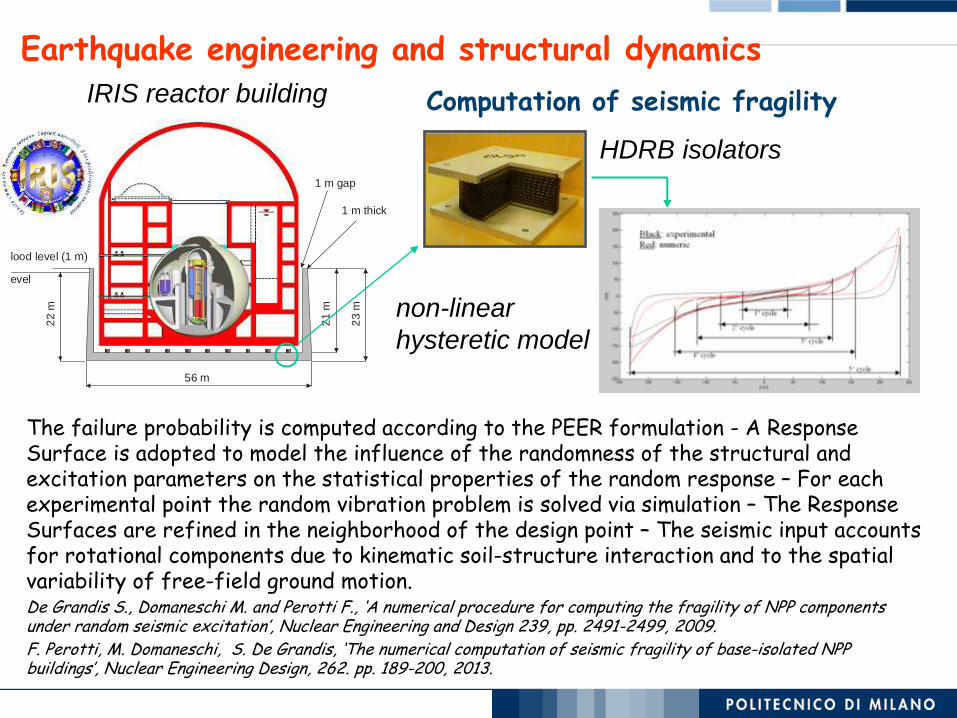
Computation of seismic fragility
50 m
23 m
22 m
21 m
56 m
1 m gap
Ground level
Flood level (1 m)
1 m thick
HDRB isolators
non-linear
hysteretic model
The failure probability is computed according to the PEER formulation - A Response Surface is adopted to model the influence of the randomness of the structural and excitation parameters on the statistical properties of the random response – For each experimental point the random vibration problem is solved via simulation – The Response Surfaces are refined in the neighborhood of the design point – The seismic input accounts for rotational components due to kinematic soil-structure interaction and to the spatial variability of free-field ground motion. De Grandis S., Domaneschi M. and Perotti F., ‘A numerical procedure for computing the fragility of NPP components under random seismic excitation’, Nuclear Engineering and Design 239, pp. 2491-2499, 2009. F. Perotti, M. Domaneschi, S. De Grandis, ‘The numerical computation of seismic fragility of base-isolated NPP buildings’, Nuclear Engineering Design, 262. pp. 189-200, 2013.
IRIS reactor building

NORTH
WING WEST
WING
SOUTH
WING
BEFORE
Nort
h
Wing
AFTER
THE COLLAPSE MECHANISM
Grey: REI 60
wall and floor
still standing
Green:
collapsed floor
In between:
cross-section
of 18-29 failed
in shear
Shear failure of beams, 1° floor
Columns failure, ground floor
Earthquake engineering and structural dynamics
Forensic Engineering and analysis of progressive collapse

Multiphysics and multi-scale experimental studies of materials and models
Internal erosion and piping
Small scale model for soil-atmosphere interaction
Chemo-electro-hydro-mechanical behaviour
Field monitoring of water exchanges
Geomechanics and geotechnical engineering
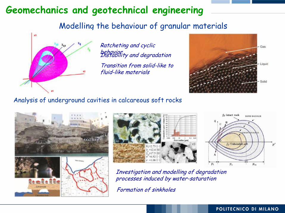
Modelling the behaviour of granular materials
Transition from solid-like to fluid-like materials
Ratcheting and cyclic behavior Instability and degradation
Analysis of underground cavities in calcareous soft rocks
Investigation and modelling of degradation processes induced by water-saturation
Formation of sinkholes
Geomechanics and geotechnical engineering

Retention, hydraulic conductivity, stiffness and strength
Simulation of pore size density function of a compacted clay
Water retention curve for Perlite at various densities
Multiscale approach: from microstructure to the field
Multiphysics actions: drying/wetting – freezing/thawing – electrical (electroosmotic) -
chemical
Water retention curve for compacted Boom clay
As compacted bentonite
Saturated 0.5M NaCl
Saturated distilled water
Modelling the behaviour of compacted materials of increasing activity
Geomechanics and geotechnical engineering
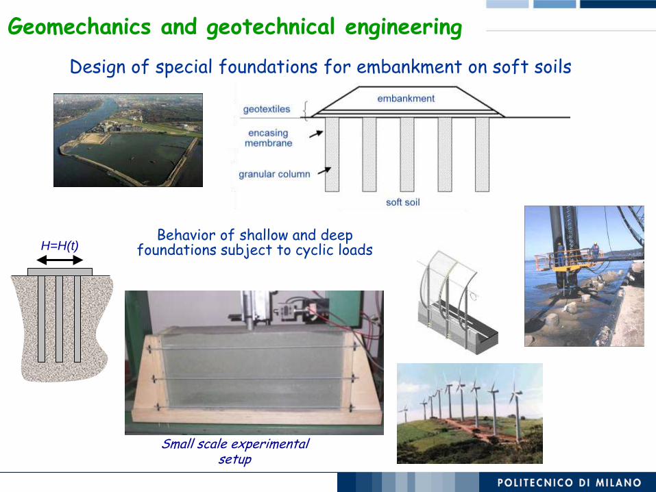
Small scale experimental setup
H=H(t) Behavior of shallow and deep
foundations subject to cyclic loads
Design of special foundations for embankment on soft soils
Geomechanics and geotechnical engineering

Cracking phenomena in clayey soils undergoing desiccation processes
Durability, maintanance and mitigation actions for
Barriers, Dykes, Embankments, Slopes
Geomechanics and geotechnical engineering
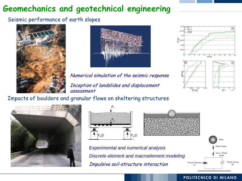
Impacts of boulders and granular flows on sheltering structures
Seismic performance of earth slopes
Experimental and numerical analysis
Discrete element and macroelement modeling
Impulsive soil-structure interaction
Numerical simulation of the seismic response
Inception of landslides and displacement assessment
Geomechanics and geotechnical engineering

Tunneling in difficult conditions
Stress in a tunnel liner in squeezing conditions
SOFTENING and SQUEEZING GROUND CONDITION
GROUND IMPROVEMENT and SOIL NAIL STABILISATION at the tunnel face
for low enthalpy geothermal energy sources
Soil thermal drift and temperature field
in a thermo-active diaphragm wall
PIPE LAYOUT OPTIMISATION
EFFECTS on SOIL TEMPERATURE
and on SOIL-STRUCTURE
INTERACTION
Thermo-active Geostructures
Design of structural intervention measures for landslide risk
mitigation
Geomechanics and geotechnical engineering