
Protocolo AES EBU
20
SPECIFICATION OF THE DIGITAL AUDIO INTERFACE (The AES/EBU interface) Tech. 3250-E - Third edition 2004 CONTENTS 1. Scope........... .................................................................................................................................................. ......2 2. Inte rfac e format....................................................................................................................................................2 2.1. Ter minology........ .........................................................................................................................................2 2.2. Str uct ur e of for mat....................................................................................................................................... .3 2.3. Channel coding... ..........................................................................................................................................5 2.4. Pr eamble s .................................................................................................................................................. ...5 2.5. Va lidity bit ...................................................................................................................................................6 3. User data format................................................................................................................................................... 6 4. Cha nne l sta tus for ma t ...........................................................................................................................................6 5. Interface format impl emen tatio n .........................................................................................................................12 5.1. Gen era l...... ............................................................................................................................................ .....12 5.2. Trans mit ter .................................................................................................................................................12 5.3. Rec eivers.............................................................................................................................................. ......13 6. Ele ctr ica l req uir ements.......................................................................................................................................13 6.1. Ge ner al characteristic ..................................................................................................................................13 6.2. Lin e dri ver cha racter ist ics ......................................................................................................................... ..14 6.3. Line rec eiver cha rac ter istics........................................................................................................................15 6.4. Connec tor s ............................................................................................................................................ .....16 Appendix 1 Generation of the CRCC (Byte 23) for channel status...............................................................................17 Appe ndix 2 AES /EBU signals on Stru ctur ed Wiri ng...................................................................................................19 Bibliography..............................................................................................................................................................20 European Broadcasting Union Ancienne Route 17A, CH-1218 Grand-Sac onnex (Geneva) Switze rland
-
Upload
edson-francisco-silva -
Category
Documents
-
view
238 -
download
1
Transcript of Protocolo AES EBU
7/21/2019 Protocolo AES EBU
http://slidepdf.com/reader/full/protocolo-aes-ebu 1/20
SPECIFICATION OF THE DIGITAL AUDIO INTERFACE
(The AES/EBU interface)
Tech. 3250-E - Third edition 2004
CONTENTS
1. Scope...................................................................................................................................................................2
2. Interface format................................................................................................... .................................................2
2.1. Terminology.................................................................................................................................................2
2.2. Structure of format........................................................................................................................................3
2.3. Channel coding.............................................................................................................................................5
2.4. Preambles .....................................................................................................................................................5
2.5. Validity bit ...................................................................................................................................................6
3. User data format...................................................................................................................................................6
4. Channel status format ...........................................................................................................................................6
5. Interface format implementation .........................................................................................................................12
5.1. General.......................................................................................................................................................12
5.2. Transmitter .................................................................................................................................................12
5.3. Receivers....................................................................................................................................................13
6. Electrical requirements.......................................................................................................................................13
6.1. General characteristic..................................................................................................................................136.2. Line driver characteristics ...........................................................................................................................14
6.3. Line receiver characteristics........................................................................................................................15
6.4. Connectors .................................................................................................................................................16
Appendix 1 Generation of the CRCC (Byte 23) for channel status...............................................................................17
Appendix 2 AES/EBU signals on Structured Wiring...................................................................................................19
Bibliography..............................................................................................................................................................20
European Broadcasting Union
Ancienne Route 17A, CH-1218 Grand-Saconnex (Geneva) Switzerland
7/21/2019 Protocolo AES EBU
http://slidepdf.com/reader/full/protocolo-aes-ebu 2/20
tech 3250 EBU - Specification of the digital audio interface
2
Specification of the digital audio interface
(The AES/EBU interface)
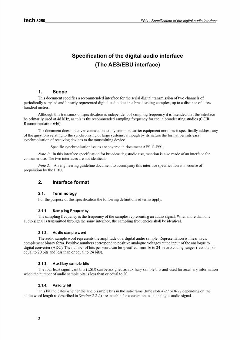
1. Scope
This document specifies a recommended interface for the serial digital transmission of two channels of
periodically sampled and linearly represented digital audio data in a broadcasting complex, up to a distance of a fewhundred metres,
Although this transmission specification is independent of sampling frequency it is intended that the interface
be primarily used at 48 kHz, as this is the recommended sampling frequency for use in broadcasting studios (CCIR Recommendation 646).
The document does not cover connection to any common carrier equipment nor does it specifically address any
of the questions relating to the synchronising of large systems, although by its nature the format permits easysynchronisation of receiving devices to the transmitting device.
Specific synchronisation issues are covered in document AES 1l-l991.
Note 1: In this interface specification for broadcasting studio use, mention is also made of an interface for consumer use. The two interfaces are not identical.
Note 2: An engineering guideline document to accompany this interface specification is in course of preparation by the EBU.
2. Interface format
2.1. Terminology
For the purpose of this specification the following definitions of terms apply.
2.1.1. Sampling Frequency
The sampling frequency is the frequency of the samples representing an audio signal. When more than oneaudio signal is transmitted through the same interface, the sampling frequencies shall be identical.
2.1.2. Audio sample word
The audio sample word represents the amplitude of a digital audio sample. Representation is linear in 2'scomplement binary form. Positive numbers correspond to positive analogue voltages at the input of the analogue todigital converter (ADC). The number of bits per word can be specified from 16 to 24 in two coding ranges (less than or equal to 20 bits and less than or equal to 24 bits).
2.1.3. Auxiliary sample bits
The four least significant bits (LSB) can be assigned as auxiliary sample bits and used for auxiliary informationwhen the number of audio sample bits is less than or equal to 20.
2.1.4. Validity bit
This bit indicates whether the audio sample bits in the sub-frame (time slots 4-27 or 8-27 depending on theaudio word length as described in Section 2.2.1.) are suitable for conversion to an analogue audio signal.
7/21/2019 Protocolo AES EBU
http://slidepdf.com/reader/full/protocolo-aes-ebu 3/20
EBU - Specification of the digital audio interface tech 3250
3
2.1.5. Channel status
The channel status carries, in a fixed format derived from the block (see Section 2. 1. 11.), informationassociated with each audio channel, which is decodable by any interface user.
2.1.6. User data
The user data channel is provided to carry any other information.
2.1.7. Parity bit
The parity bit is provided to permit the detection of an odd number of errors resulting from malfunctions in the
interface.
2.1.8. Preambles
Preambles are specific patterns used for synchronisation. There are three different preambles (see Section 2.4.).
2.1.9. Sub-frame
The sub-frame is a fixed structure used to carry the information described in Sections 2.1.1. to 2.1.8. (SeeSections 2.2.1. and 2.2.2.).
2.1.10. Frame
The frame is a sequence of two successive and associated sub-frames.
2.1.11. Block
The block is a group of 192 consecutive frames. The start of a block is designated by a special sub-frame preamble (see Section 2.4.).
2.1.12. Channel coding
The channel coding describes the method by which the binary digits are represented for transmission through
the interface.
2.1.13. Unit interval UI
Shortest nominal time interval in the coding scheme
2.1.14. Interface jitter
Deviation in timing of interface data transitions (zero crossings) when measured with respect to an ideal clock
2.1.15. Intrinsic jitter
Output interface jitter of a device that is either free running or is synchronized to a jitter-free reference
2.1.16. Jitter gain
Rate of transmission of frames
2.2. Structure of format
2.2.1. Sub-frame format
Each sub-frame is divided into 32 time slots, numbered from 0 to 31 (see fig 1)
Time slots 0 to 3 (preamble) carry one of the three permitted preambles (see Fig. 2) (see Sections 2.2.2. and2.4; see also Fig. 2).
Time slots 4 to 27 (audio samples word) carry the audio sample word in linear 2's complement representation.
The most significant bit (MSB) is carried by time slot 27.When a 24-bit coding range is used, the LSB is in time slot 4 (see Fig. 1a).
7/21/2019 Protocolo AES EBU
http://slidepdf.com/reader/full/protocolo-aes-ebu 4/20
tech 3250 EBU - Specification of the digital audio interface
4
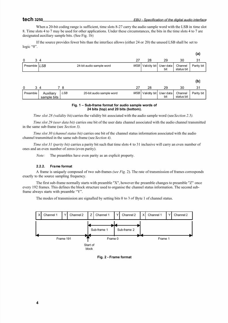
When a 20-bit coding range is sufficient, time slots 8-27 carry the audio sample word with the LSB in time slot8. Time slots 4 to 7 may be used for other applications. Under these circumstances, the bits in the time slots 4 to 7 aredesignated auxiliary sample bits. (See Fig. 1b)
If the source provides fewer bits than the interface allows (either 24 or 20) the unused LSB shall be set tologic “0”.
(a)
0 3 4 27 28 29 30 31
Preamble LSB 24-bit audio sample word MSB Validity bit User databit
Channelstatus bit
Parity bit
(b)
0 3 4 7 8 27 28 29 30 31
Preamble Auxiliarysample bits
LSB 20-bit audio sample word MSB Validity bit User databit
Channelstatus bit
Parity bit
Fig. 1 – Sub-frame format for audio sample words of 24 bits (top) and 20 bits (bottom).
Time slot 28 (validity bit) carries the validity bit associated with the audio sample word (see Section 2.5).
Time slot 29 (user data bit) carries one bit of the user data channel associated with the audio channel transmittedin the same sub-frame (see Section 3).
Time slot 30 (channel status bit) carries one bit of the channel status information associated with the audiochannel transmitted in the same sub-frame (see Section 4).
Time slot 31 (parity bit) carries a parity bit such that time slots 4 to 31 inclusive will carry an even number of ones and an even number of zeros (even parity).
Note: The preambles have even parity as an explicit property.
2.2.2. Frame format
A frame is uniquely composed of two sub-frames (see Fig. 2). The rate of transmission of frames correspondsexactly to the source sampling frequency.
The first sub-frame normally starts with preamble "X", however the preamble changes to preamble "Z" onceevery 192 frames. This defines the block structure used to organise the channel status information. The second sub-
frame always starts with preamble “Y”.
The modes of transmission are signalled by setting bits 0 to 3 of Byte 1 of channel status.
Channel 1 Channel 2X Y Channel 1 Channel 2Z Y Channel 1 Channel 2X Y
Sub-frame 1 Sub-frame 2
Frame 1Frame 191 Frame 0
Start of
block
Fig. 2 - Frame format
7/21/2019 Protocolo AES EBU
http://slidepdf.com/reader/full/protocolo-aes-ebu 5/20
EBU - Specification of the digital audio interface tech 3250
5
Clock
(2 times bit rate)
Source c oding
Channel coding
(bi-phase mark) 0
01
1
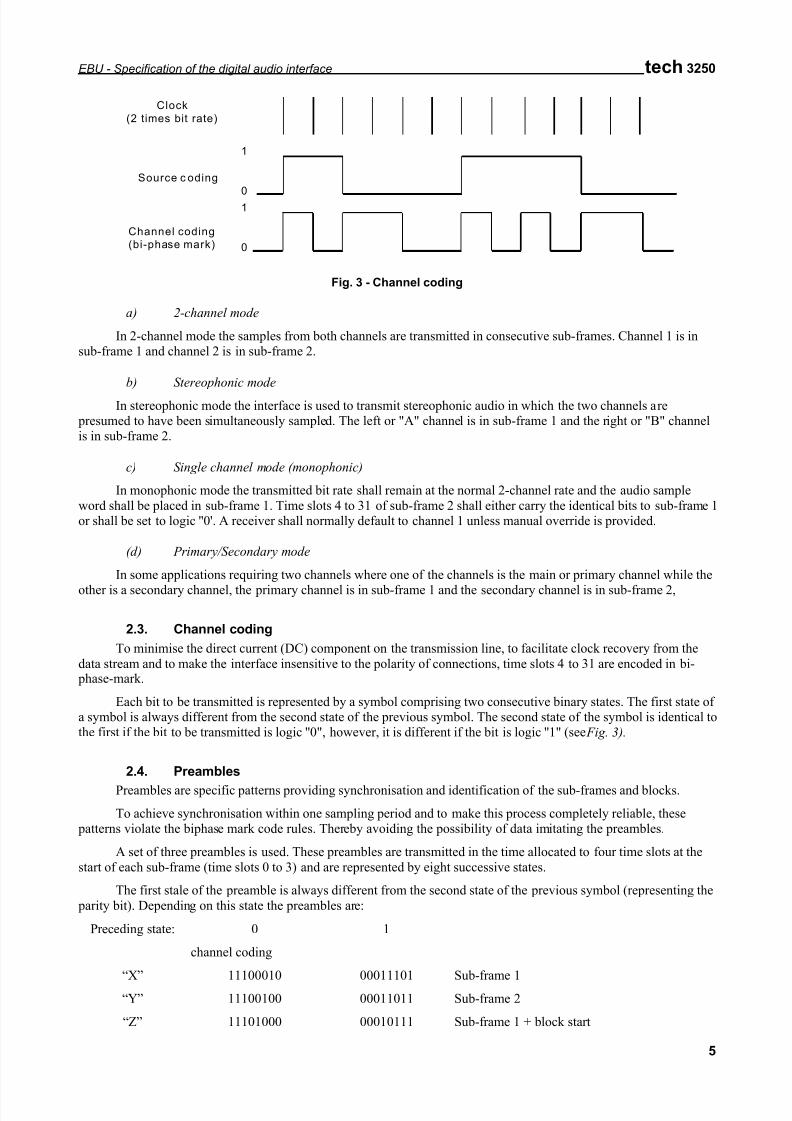
Fig. 3 - Channel coding
a) 2-channel mode
In 2-channel mode the samples from both channels are transmitted in consecutive sub-frames. Channel 1 is insub-frame 1 and channel 2 is in sub-frame 2.
b) Stereophonic mode
In stereophonic mode the interface is used to transmit stereophonic audio in which the two channels are presumed to have been simultaneously sampled. The left or "A" channel is in sub-frame 1 and the right or "B" channelis in sub-frame 2.
c) Single channel mode (monophonic)
In monophonic mode the transmitted bit rate shall remain at the normal 2-channel rate and the audio sample
word shall be placed in sub-frame 1. Time slots 4 to 31 of sub-frame 2 shall either carry the identical bits to sub-frame 1or shall be set to logic ''0'. A receiver shall normally default to channel 1 unless manual override is provided.
(d) Primary/Secondary mode
In some applications requiring two channels where one of the channels is the main or primary channel while the
other is a secondary channel, the primary channel is in sub-frame 1 and the secondary channel is in sub-frame 2,
2.3. Channel coding
To minimise the direct current (DC) component on the transmission line, to facilitate clock recovery from the
data stream and to make the interface insensitive to the polarity of connections, time slots 4 to 31 are encoded in bi- phase-mark.
Each bit to be transmitted is represented by a symbol comprising two consecutive binary states. The first state of a symbol is always different from the second state of the previous symbol. The second state of the symbol is identical tothe first if the bit to be transmitted is logic ''0", however, it is different if the bit is logic ''1" (see Fig. 3).
2.4. Preambles
Preambles are specific patterns providing synchronisation and identification of the sub-frames and blocks.
To achieve synchronisation within one sampling period and to make this process completely reliable, these patterns violate the biphase mark code rules. Thereby avoiding the possibility of data imitating the preambles.
A set of three preambles is used. These preambles are transmitted in the time allocated to four time slots at the
start of each sub-frame (time slots 0 to 3) and are represented by eight successive states.
The first stale of the preamble is always different from the second state of the previous symbol (representing the
parity bit). Depending on this state the preambles are:
Preceding state: 0 1
channel coding
“X” 11100010 00011101 Sub-frame 1“Y” 11100100 00011011 Sub-frame 2
“Z” 11101000 00010111 Sub-frame 1 + block start
7/21/2019 Protocolo AES EBU
http://slidepdf.com/reader/full/protocolo-aes-ebu 6/20
tech 3250 EBU - Specification of the digital audio interface
6
As with biphase code, these preambles are DC free and provide clock recovery. They differ in at least two statesfrom any valid biphase sequence.
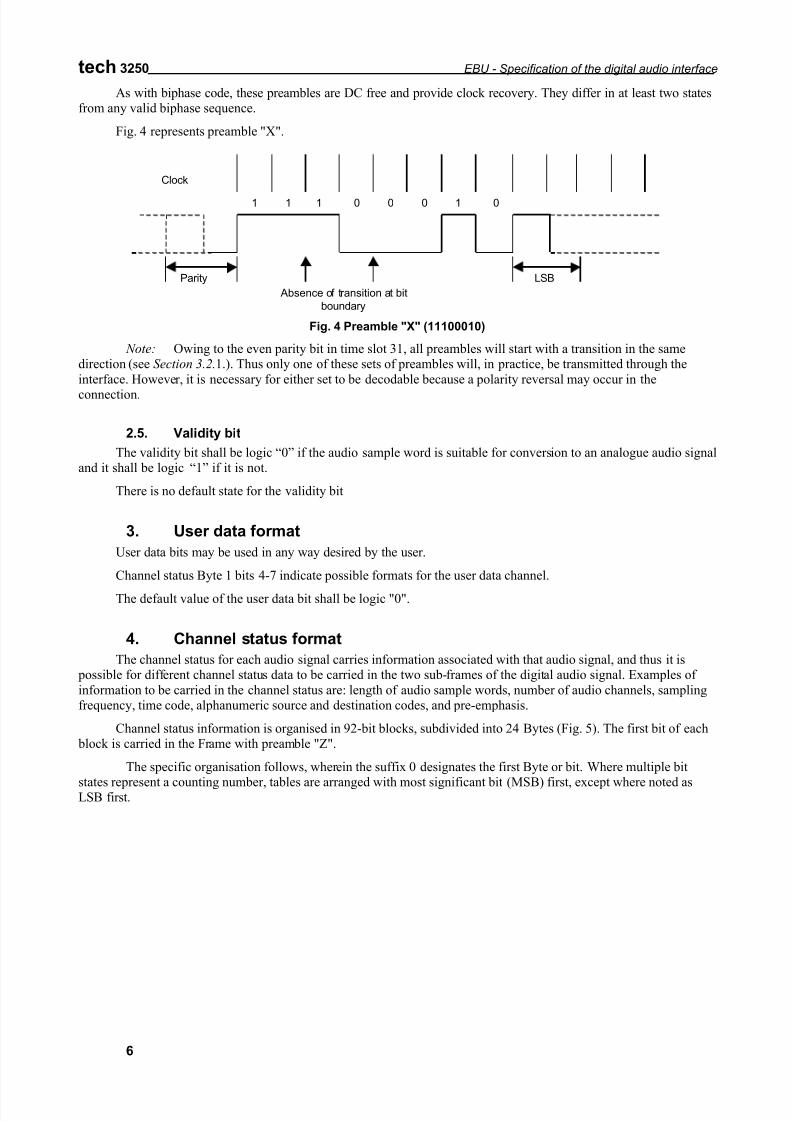
Fig. 4 represents preamble "X".
01 11 1 0 0 0
Absence of transition at bit
boundary
LSBParity
Clock
Fig. 4 Preamble "X" (11100010)
Note: Owing to the even parity bit in time slot 31, all preambles will start with a transition in the samedirection (see Section 3.2.1.). Thus only one of these sets of preambles will, in practice, be transmitted through the
interface. However, it is necessary for either set to be decodable because a polarity reversal may occur in the
connection.
2.5. Validity bit
The validity bit shall be logic “0” if the audio sample word is suitable for conversion to an analogue audio signaland it shall be logic “1” if it is not.
There is no default state for the validity bit
3. User data format
User data bits may be used in any way desired by the user.
Channel status Byte 1 bits 4-7 indicate possible formats for the user data channel.
The default value of the user data bit shall be logic "0".
4. Channel status format
The channel status for each audio signal carries information associated with that audio signal, and thus it is possible for different channel status data to be carried in the two sub-frames of the digital audio signal. Examples of
information to be carried in the channel status are: length of audio sample words, number of audio channels, samplingfrequency, time code, alphanumeric source and destination codes, and pre-emphasis.
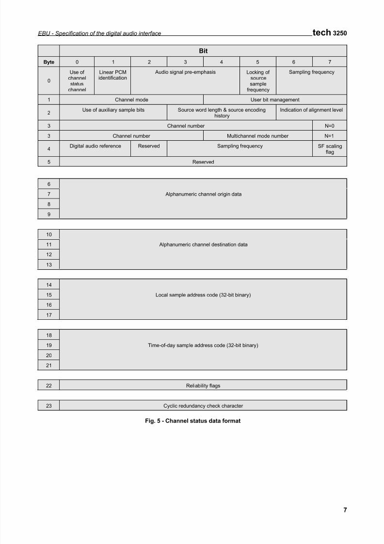
Channel status information is organised in 92-bit blocks, subdivided into 24 Bytes (Fig. 5). The first bit of each block is carried in the Frame with preamble "Z".
The specific organisation follows, wherein the suffix 0 designates the first Byte or bit. Where multiple bit
states represent a counting number, tables are arranged with most significant bit (MSB) first, except where noted asLSB first.
7/21/2019 Protocolo AES EBU
http://slidepdf.com/reader/full/protocolo-aes-ebu 7/20
EBU - Specification of the digital audio interface tech 3250
7
Bit
Byte 0 1 2 3 4 5 6 7
0
Use of channelstatus
channel
Linear PCMidentification
Audio signal pre-emphasis Locking of sourcesample
frequency
Sampling frequency
1 Channel mode User bit management
2Use of auxiliary sample bits Source word length & source encoding
historyIndication of alignment level
3 Channel number N=0
3 Channel number Multichannel mode number N=1
4Digital audio reference Reserved Sampling frequency SF scaling
flag
5 Reserved
6
7 Alphanumeric channel origin data
8
9
10
11 Alphanumeric channel destination data
12
13
14
15 Local sample address code (32-bit binary)
16
17
18
19 Time-of-day sample address code (32-bit binary)
20
21
22 Reliability flags
23 Cyclic redundancy check character
Fig. 5 - Channel status data format
7/21/2019 Protocolo AES EBU
http://slidepdf.com/reader/full/protocolo-aes-ebu 8/20
tech 3250 EBU - Specification of the digital audio interface
8
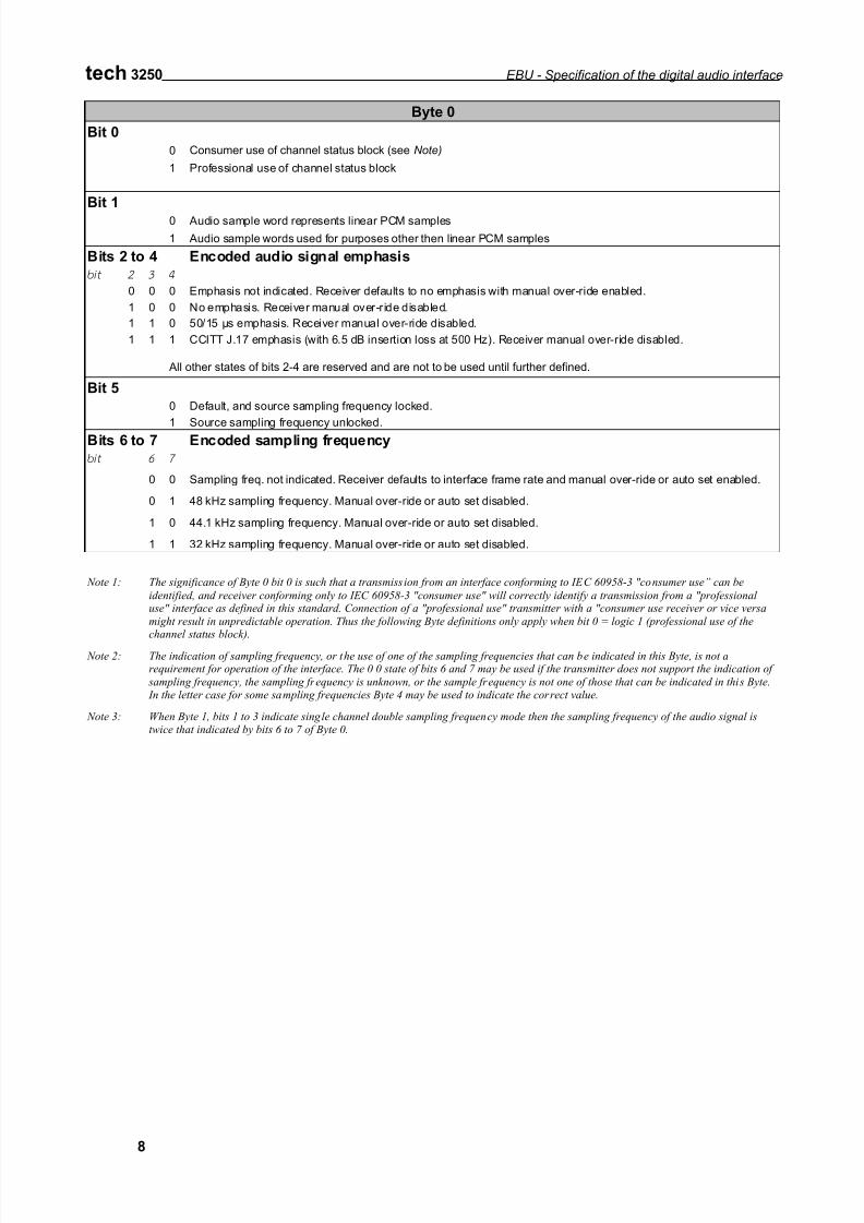
Byte 0
Bit 0
0 Consumer use of channel status block (see Note)
1 Professional use of channel status block
Bit 1
0 Audio sample word represents linear PCM samples
1 Audio sample words used for purposes other then linear PCM samples
Bits 2 to 4 Encoded audio signal emphasis
bit 2 3 4
0 0 0 Emphasis not indicated. Receiver defaults to no emphasis with manual over-ride enabled.
1 0 0 No emphasis. Receiver manual over-ride disabled.
1 1 0 50/15 µs emphasis. Receiver manual over-ride disabled.
1 1 1 CCITT J.17 emphasis (with 6.5 dB insertion loss at 500 Hz). Receiver manual over-ride disabled.
All other states of bits 2-4 are reserved and are not to be used until further defined.
Bit 50 Default, and source sampling frequency locked.
1 Source sampling frequency unlocked.Bits 6 to 7 Encoded sampling frequency
bit 6 7
0 0 Sampling freq. not indicated. Receiver defaults to interface frame rate and manual over-ride or auto set enabled.
0 1 48 kHz sampling frequency. Manual over-ride or auto set disabled.
1 0 44.1 kHz sampling frequency. Manual over-ride or auto set disabled.
1 1 32 kHz sampling frequency. Manual over-ride or auto set disabled.
Note 1: The significance of Byte 0 bit 0 is such that a transmission from an interface conforming to IEC 60958-3 "consumer use” can be
identified, and receiver conforming only to IEC 60958-3 "consumer use" will correctly identify a transmission from a "professional use" interface as defined in this standard. Connection of a "professional use" transmitter with a "consumer use receiver or vice versa
might result in unpredictable operation. Thus the following Byte definitions only apply when bit 0 = logic 1 (professional use of thechannel status block).
Note 2: The indication of sampling frequency, or the use of one of the sampling frequencies that can be indicated in this Byte, is not arequirement for operation of the interface. The 0 0 state of bits 6 and 7 may be used if the transmitter does not support the indication of
sampling frequency, the sampling frequency is unknown, or the sample frequency is not one of those that can be indicated in this Byte. In the letter case for some sampling frequencies Byte 4 may be used to indicate the correct value.
Note 3: When Byte 1, bits 1 to 3 indicate single channel double sampling frequency mode then the sampling frequency of the audio signal istwice that indicated by bits 6 to 7 of Byte 0.
7/21/2019 Protocolo AES EBU
http://slidepdf.com/reader/full/protocolo-aes-ebu 9/20
EBU - Specification of the digital audio interface tech 3250
9
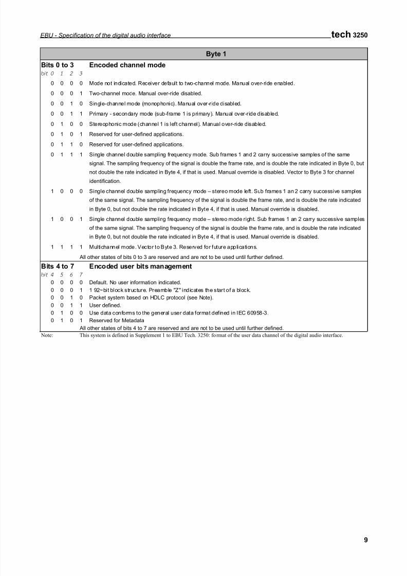
Byte 1
Bits 0 to 3 Encoded channel modebit 0 1 2 3
0 0 0 0 Mode not indicated. Receiver default to two-channel mode. Manual over-ride enabled.
0 0 0 1 Two-channel mode. Manual over-ride disabled.
0 0 1 0 Single-channel mode (monophonic). Manual over-ride disabled.
0 0 1 1 Primary - secondary mode (sub-frame 1 is primary). Manual over-ride disabled.
0 1 0 0 Stereophonic mode (channel 1 is left channel). Manual over-ride disabled.
0 1 0 1 Reserved for user-defined applications.
0 1 1 0 Reserved for user-defined applications.
0 1 1 1 Single channel double sampling frequency mode. Sub frames 1 and 2 carry successive samples of the same
signal. The sampling frequency of the signal is double the frame rate, and is double the rate indicated in Byte 0, but
not double the rate indicated in Byte 4, if that is used. Manual override is disabled. Vector to Byte 3 for channel
identification.
1 0 0 0 Single channel double sampling frequency mode – stereo mode left. Sub frames 1 an 2 carry successive samples
of the same signal. The sampling frequency of the signal is double the frame rate, and is double the rate indicatedin Byte 0, but not double the rate indicated in Byte 4, if that is used. Manual override is disabled.
1 0 0 1 Single channel double sampling frequency mode – stereo mode right. Sub frames 1 an 2 carry successive samples
of the same signal. The sampling frequency of the signal is double the frame rate, and is double the rate indicated
in Byte 0, but not double the rate indicated in Byte 4, if that is used. Manual override is disabled.
1 1 1 1 Multichannel mode. Vector to Byte 3. Reserved for future applications.
All other states of bits 0 to 3 are reserved and are not to be used until further defined.
Bits 4 to 7 Encoded user bits managementbit 4 5 6 7
0 0 0 0 Default. No user information indicated.
0 0 0 1 1 92~bit block structure. Preamble "Z" indicates the start of a block.
0 0 1 0 Packet system based on HDLC protocol (see Note).
0 0 1 1 User defined.
0 1 0 0 Use data conforms to the general user data format defined in IEC 60958-3.
0 1 0 1 Reserved for Metadata
All other states of bits 4 to 7 are reserved and are not to be used until further defined.
Note: This system is defined in Supplement 1 to EBU Tech. 3250: format of the user data channel of the digital audio interface.
7/21/2019 Protocolo AES EBU
http://slidepdf.com/reader/full/protocolo-aes-ebu 10/20
tech 3250 EBU - Specification of the digital audio interface
10
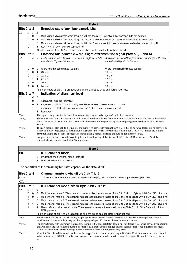
Byte 2
Bits 0 to 2 Encoded use of auxiliary sample bits
bit 0 1 2
0 0 0 Maximum audio sample word length is 20 bits (default). Use of auxiliary sample bits not defined
0 0 1 Maximum audio sample word length is 24 bits, Auxiliary sample bits used for main audio sample data
0 1 0 Maximum audio sample word length is 20 bits, Aux. sample bits carry a single coordination signal (Note 1)
0 1 1 Reserved for user-defined appl ications All other states of bits 0-2 are reserved and shall not be used until further defined
Bits 3 to 5 Encoded audio sample word length of transmitted signal (Notes 2, 3 and 4)
bit 3 4 5 Audio sample word length H maximum length is 24 bits,
as indicated by bits 0-2 above
Audio sample word length if maximum length is 20 bits,
as indicated by bits 0-2 above
0 0 0 Word length not indicated (default) Word length not indicated (default)
0 0 1 23 bits 19 bits
0 1 0 22 bits 18 bits
0 1 1 21 bits 17 bits
1 0 0 20 bits 16 bits
1 0 1 24 bits 20 bits
All other states of bits 3 - 5 are reserved and shall not be used until further defined,
Bits 6 to 7 Indication of alignment levelbit 6 7
0 0 Alignment level not indicated
0 1 Alignment to SMPTE RP155, alignment level is 20 dB below maximum code
1 0 Alignment to EBU R68, alignment level is 18.06 dB below maximum code
1 1 Reserved
Note 1: The signal coding used for the co-ordination channel is described in Appendix 1 to this document.
Note 2: The default state of bits 3-5 indicates that the transmitter does not specify the number of active bits within the 20 or 24 bits coding
range. The receiver should default to the maximum number of bits specified by the coding range and enable manual override or
auto set.
Note 3: The non-default states of bits 3-5 indicate the number of active bits within the 20 or 24 bits coding range that might be active. This
is also an indirect expression of the number of LSBs that are certain to be inactive which is equal to 20 or 24 minus the number
corresponding to the bit state, The receiver should disable manual override and auto set for these bit states.
Note 4: Irrespective of the audio sample word length as indicated by any of the states of bits 3-5, the MSB is in time slot 27 of the
transmitted sub-frame as specified in Section 2.2.1.
Byte 3
Bit 7 Multichannel mode0 Undefined multichannel mode (default)
1 Defined multichannel modes
The definition of the remaining bit states depends on the state of bit 7.
Bits 0 to 6 Channel number, when Byte 3 bit 7 is 0
Value The channel number is the numeric value of the Byte, with bit 0 as the least significant bit, plus one.
OR
Bits 0 to 6 Multichannel mode, when Byte 3 bit 7 is “1”bit 4 5 6
0 0 0 Multichannel mode 0. The channel number is the numeric value of bits 0 to 3 of this Byte with bit 0 = LSB, plus one
1 0 0 Multichannel mode 1. The channel number is the numeric value of bits 0 to 3 of this Byte with bit 0 = LSB, plus one
0 1 0 Multichannel mode 2. The channel number is the numeric value of bits 0 to 3 of this Byte with bit 0 = LSB, plus one
1 1 0 Multichannel mode 3. The channel number is the numeric value of bits 0 to 3 of this Byte with bit 0 = LSB, plus one
1 1 1 User-defined multichannel mode. The channel number is the numeric value of bits 0 to 3 of this Byte with bit 0 =LSB, plus one
All other states of bits 4 to 6 are reserved and are not to be used until further defined
Note 1: The defined multichannel modes identify mappings between channel numbers and function. The standard mappings are under
consideration. Some mappings may involve groupings of up to 32 channels by combining two modes.
Note 2: For compatibility with equipment that is only sensitive to the channel status data in one sub frame the channel carried by sub frame
2 may indicate the same channel number as channel 1. In that case it is implicit that the second channel has a number one higher
than the channel of sub frame 1 except in single channel double sampling frequency mode.
Note 3: When bit 7 is 1 the 4-bit channel number can be mapped to the channel numbering in bits 20 to 23 of the consumer mode channel
status defined in IEC 60958-3. In this case channel A of consumer mode maps to channel 2, channel B maps to channel 3 and so
on.
7/21/2019 Protocolo AES EBU
http://slidepdf.com/reader/full/protocolo-aes-ebu 11/20
EBU - Specification of the digital audio interface tech 3250
11
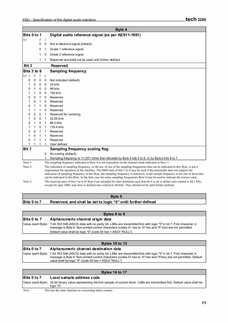
Byte 4
Bits 0 to 1 Digital audio reference signal (as per AES11-1991)
bit 0 1
0 0 Not a reference signal (default).
0 1 Grade 1 reference signal.
1 0 Grade 2 reference signal.
1 1 Reserved and shall not be used until further defined.
Bit 2 Reserved
Bits 3 to 6 Sampling frequencybit 3 4 5 6
0 0 0 0 Not indicated (default)
1 0 0 0 24 kHz
0 1 0 0 96 kHz
1 1 0 0 192 kHz
0 0 1 0 Reserved
1 0 1 0 Reserved
0 1 1 0 Reserved
1 1 1 0 Reserved
0 0 0 1 Reserved for vectoring
1 0 0 1 22.05 kHz
0 1 0 1 88.2 kHz
1 1 0 1 176.4 kHz
0 0 1 1 Reserved
1 0 1 1 Reserved
0 1 1 1 Reserved
1 1 1 1 User defined
Bit 7 Sampling frequency scaling flag
0 No scaling (default)
1 Sampling frequency is 1/1,001 times that indicated by Byte 4 bits 3 to 6, or by Byte 0 bits 6 to 7
Note 1: The sampling frequency indicated in Byte 4 is not dependent on the channel mode indicated in Byte 1.
Note 2: The indication of sampling frequency, or the use of one of the sampling frequencies that can be indicated in this Byte, is not a
requirement for operation of the interface. The 0000 state of bits 3 to 6 may be used if the transmitter does not support theindication of sampling frequency in this Byte, the sampling frequency is unknown, or the sample frequency is not one of those that
can be indicated in this Byte. In the later case for some sampling frequencies Byte 0 may be used to indicate the correct value.
Note 3: The reserved sates of bits 3 to 6 of Byte 4 are intended for later definition such that bit 6 is set to define rates related to 44,1 kHz,
except for state 1000, and clear to defined rates related to 48 kHz. They should not be until further defined.
Byte 5
Bits 0 to 7 Reserved, and shall be set to logic “0” until further defined
Bytes 6 to 9
Bits 0 to 7 Alphanumeric channel origin data
Value (each Byte) 7-bit ISO 646 (ASCII) data with no parity bit. LSBs are transmitted first with logic "0" in bit 7. First character inmessage is Byte 6. Non-printed control characters (codes 01 hex to 1F hex and 7F hex) are not permitted.
Default value shall be logic "0" (code 00 hex = ASCII "NULL")
Bytes 10 to 13
Bits 0 to 7 Alphanumeric channel destination dataValue (each Byte) 7-bit ISO 646 (ASCII) data with no parity bit. LSBs are transmitted first with logic "0" in bit 7. First character in
message is Byte 6. Non-printed control characters (codes 01 hex to 1F hex and 7Fhex) are not permitted. Defaultvalue shall be logic "0" (code 00 hex = ASCII "NULL")
Bytes 14 to 17
Bits 0 to 7 Local sample address code
Value (each Byte) 32-bit binary value representing the first sample of current block. LSBs are transmitted first. Default value shall belogic "0".
Note: This has the same function as a recording index counter.
7/21/2019 Protocolo AES EBU
http://slidepdf.com/reader/full/protocolo-aes-ebu 12/20
tech 3250 EBU - Specification of the digital audio interface
12
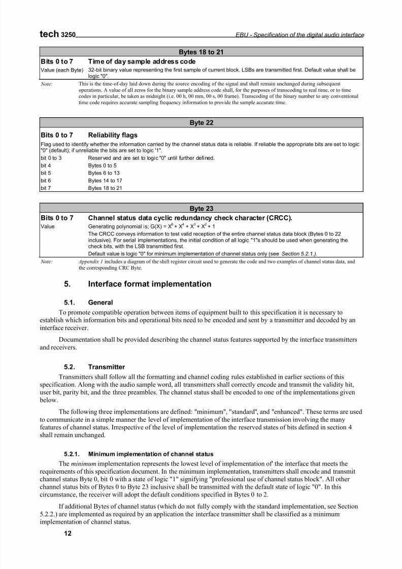
Bytes 18 to 21
Bits 0 to 7 Time of day sample address code
Value (each Byte) 32-bit binary value representing the first sample of current block. LSBs are transmitted first. Default value shall belogic "0".
Note: This is the time-of-day laid down during the source encoding of the signal and shall remain unchanged during subsequent
operations. A value of all zeros for the binary sample address code shall, for the purposes of transcoding to real time, or to time
codes in particular, be taken as midnight (i.e. 00 h, 00 mm, 00 s, 00 frame). Transcoding of the binary number to any conventional
time code requires accurate sampling frequency information to provide the sample accurate time.
Byte 22
Bits 0 to 7 Reliability flags
Flag used to identify whether the information carried by the channel status data is reliable. If reliable the appropriate bits are set to logic"0" (default); if unreliable the bits are set to logic '1".
bit 0 to 3 Reserved and are set to logic "0" until further defined.
bit 4 Bytes 0 to 5
bit 5 Bytes 6 to 13
bit 6 Bytes 14 to 17
bit 7 Bytes 18 to 21
Byte 23
Bits 0 to 7 Channel status data cyclic redundancy check character (CRCC).
Value Generating polynomial is; G(X) = X8+ X
4 + X
3+ X
2+ 1
The CRCC conveys information to test valid reception of the entire channel status data block (Bytes 0 to 22inclusive). For serial implementations, the initial condition of all logic "1"s should be used when generating thecheck bits, with the LSB transmitted first.
Default value is logic "0" for minimum implementation of channel status only (see Section 5.2.1.).
Note: Appendix 1 includes a diagram of the shift register circuit used to generate the code and two examples of channel status data, and
the corresponding CRC Byte.
5. Interface format implementation
5.1. General
To promote compatible operation between items of equipment built to this specification it is necessary toestablish which information bits and operational bits need to be encoded and sent by a transmitter and decoded by an
interface receiver.
Documentation shall be provided describing the channel status features supported by the interface transmitters
and receivers.
5.2. Transmitter
Transmitters shall follow all the formatting and channel coding rules established in earlier sections of thisspecification. Along with the audio sample word, all transmitters shall correctly encode and transmit the validity hit,user bit, parity bit, and the three preambles. The channel status shall be encoded to one of the implementations given
below.
The following three implementations are defined: ''minimum'', "standard'', and ''enhanced". These terms are used
to communicate in a simple manner the level of implementation of the interface transmission involving the manyfeatures of channel status. Irrespective of the level of implementation the reserved states of bits defined in section 4shall remain unchanged.
5.2.1. Minimum implementation of channel status
The minimum implementation represents the lowest level of implementation of' the interface that meets the
requirements of this specification document. In the minimum implementation, transmitters shall encode and transmitchannel status Byte 0, bit 0 with a state of logic "1" signifying "professional use of channel status block". All other channel status bits of Bytes 0 to Byte 23 inclusive shall be transmitted with the default state of logic "0". In thiscircumstance, the receiver will adopt the default conditions specified in Bytes 0 to 2.
If additional Bytes of channel status (which do not fully comply with the standard implementation, see Section
5.2.2.) are implemented as required by an application the interface transmitter shall be classified as a minimumimplementation of channel status.
7/21/2019 Protocolo AES EBU
http://slidepdf.com/reader/full/protocolo-aes-ebu 13/20
EBU - Specification of the digital audio interface tech 3250
13
It should be noted that this implementation imposes severe operational restrictions on the receiving devices thatmay be connected to it. For example, receivers implementing Byte 23 will show a CRC error when the default value of logic "0" is received as the CRCC. Also, reception of the default value for Byte 0 bits 6-7 might cause improper
operation in receiving devices not supporting manual override or auto set capabilities.
5.2.2. Standard implementation of channel status
The standard implementation provides a fundamental level of implementation that should prove sufficient for general applications in professional audio or broadcasting. In addition to conforming to the requirements describedabove for the minimum implementation, a standard implementation interface transmitter shall correctly encode andtransmit all channel status bits in Byte 0, Byte 1, Byte 2 and Byte 23 (CRCC) in the manner specified in this document.
5.2.3. Enhanced implementation of channel status
In addition to conforming to the requirements described above for the standard implementation, the enhanced implementation shall provide further capabilities.
5.3. Receivers
Implementation in receivers is highly dependent on the application. Proper documentation shall be provided on
the level of implementation of the interface receiver for decoding the transmitted information (validity. user, channelstatus, parity), and on whatever subsequent action is taken by the equipment of which it is a part.
6. Electrical requirements
6.1. General characteristic
The electrical parameters of the interface are based on those defined in ITU-T Recommendation V.11 for balanced voltage digital circuits, which allow signal transmission over distances of up to a few hundred metres.
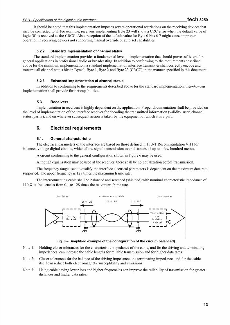
A circuit conforming to the general configuration shown in figure 6 may be used.
Although equalization may be used at the receiver, there shall be no equalization before transmission.
The frequency range used to qualify the interface electrical parameters is dependent on the maximum data ratesupported. The upper frequency is 128 times the maximum frame rate,
The interconnecting cable shall be balanced and screened (shielded) with nominal characteristic impedance of
110 Ω at frequencies from 0.1 to 128 times the maximum frame rate.
Fig. 6 – Simplified example of the configuration of the circuit (balanced)
Note 1: Holding closer tolerances for the characteristic impedance of the cable, and for the driving and terminatingimpedances, can increase the cable lengths for reliable transmission and for higher data rates.
Note 2: Closer tolerances for the balance of the driving impedance, the terminating impedance, and for the cableitself can reduce both electromagnetic susceptibility and emissions.
Note 3: Using cable having lower loss and higher frequencies can improve the reliability of transmission for greater
distances and higher data rates.
7/21/2019 Protocolo AES EBU
http://slidepdf.com/reader/full/protocolo-aes-ebu 14/20
tech 3250 EBU - Specification of the digital audio interface
14
6.2. Line driver characteristics
6.2.1. Output impedance
The line driver shall have a balanced output with an internal impedance of 110 Ω ± 20%, at frequencies from0.1 to 128 times the maximum frame rate when measured the output at terminals.
6.2.2. Signal amplitude
The signal amplitude shall lie between 2 and 7 V peak-to-peak, when measured across a 110 Ω resistor connected to the output terminals, without any interconnecting cable present.
6.2.3. Balance
Any common mode component at the output of the equipment shall be more than 30 dB below the signal atfrequencies from DC to 128 times the maximum frame rate.
6.2.4. Rise and fall times
The rise and fall times determined between the 10% and 90% amplitude points, shall be between 5 ns and
30 ns when measured across a 110Ω resistor connected to the output terminals, without any interconnecting cable
present.
Note: Operation toward the lower limit of 5 ns will improve the received eye pattern but will increase EMI at thetransmitter. Equipment must meet local regulations regarding EMI.
6.2.5. Output interface jitter
Jitter at the output of a device shall be measured as the sum of the jitter intrinsic to the device and jitter being passed through from the timing reference of the device.
6.2.5.1 Intrinsic jitter
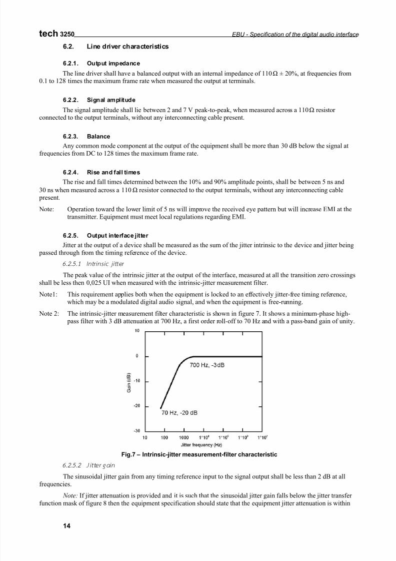
The peak value of the intrinsic jitter at the output of the interface, measured at all the transition zero crossings
shall be less then 0,025 UI when measured with the intrinsic-jitter measurement filter.
Note1: This requirement applies both when the equipment is locked to an effectively jitter-free timing reference,which may be a modulated digital audio signal, and when the equipment is free-running.
Note 2: The intrinsic-jitter measurement filter characteristic is shown in figure 7. It shows a minimum-phase high- pass filter with 3 dB attenuation at 700 Hz, a first order roll-off to 70 Hz and with a pass-band gain of unity.
Fig.7 – Intrinsic-jitter measurement-filter characteristic
6.2.5.2 Jitter gain
The sinusoidal jitter gain from any timing reference input to the signal output shall be less than 2 dB at allfrequencies.
Note: If jitter attenuation is provided and it is such that the sinusoidal jitter gain falls below the jitter transfer
function mask of figure 8 then the equipment specification should state that the equipment jitter attenuation is within
7/21/2019 Protocolo AES EBU
http://slidepdf.com/reader/full/protocolo-aes-ebu 15/20
EBU - Specification of the digital audio interface tech 3250
15
this specification. The mask imposes no additional limit on low-frequency jitter gain. The limit starts at the input-jitter of 500 Hz where it is 0 dB, and falls to –6 dB at and above 1 kHz.
-10
0
10
10 100 1000 1*10 1*10 1*10 1*10
Gain(dB)
Jitter frequency (Hz)
4 5 76
500 Hz, 0 dB
1000 Hz, -6 dB
Fig.8 – Jitter transfer-function mask
6.3. Line receiver characteristics
6.3.1. Terminating impedance
The receiver shall present a substantially resistive impedance of 110 Ω ± 20% to the interconnecting cable over the frequency hand 0.1 to 6.0 MHz, when measured across the input terminals. The application of more than onereceiver to any one line might create transmission errors due to the resulting impedance mismatch.
6.3.2. Maximum input signals
The receiver shall correctly interpret the data when connected directly to a line driver working between theextreme voltage limits specified by Section 6.2.2.
Note: In EBU document Tech. 3250 (1985) the specification for line driver signal amplitude was 10 V peak-to- peak maximum.
6.3.3. Minimum input signals
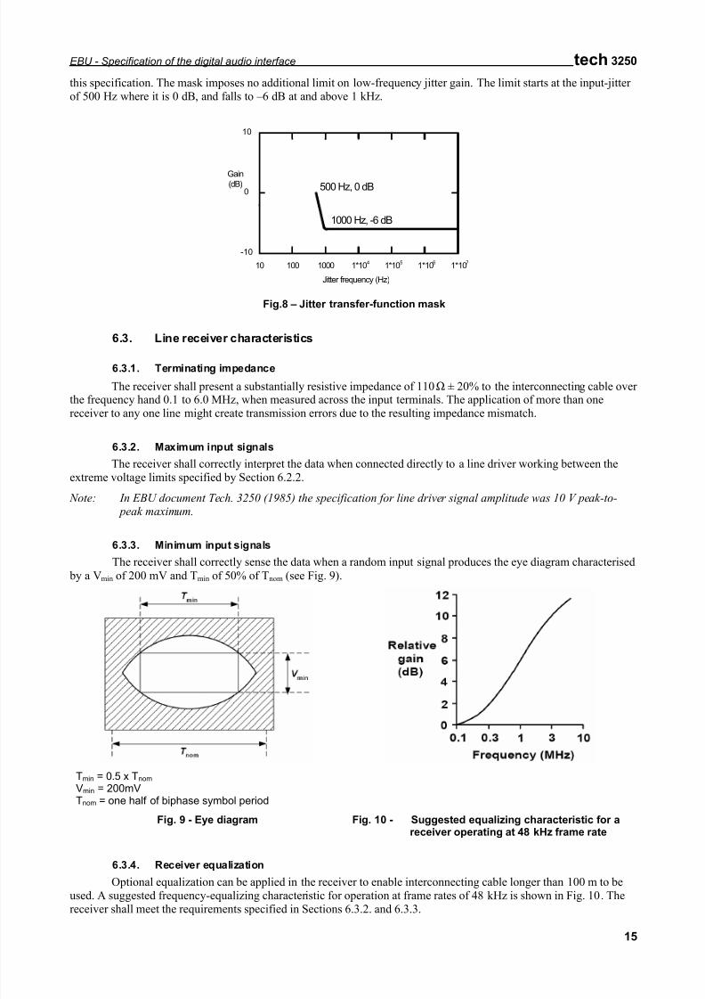
The receiver shall correctly sense the data when a random input signal produces the eye diagram characterised
by a Vmin of 200 mV and Tmin of 50% of Tnom (see Fig. 9).
Tmin = 0.5 x Tnom
Vmin = 200mVTnom = one half of biphase symbol period
Fig. 9 - Eye diagram Fig. 10 - Suggested equalizing characteristic for areceiver operating at 48 kHz frame rate
6.3.4. Receiver equalization
Optional equalization can be applied in the receiver to enable interconnecting cable longer than 100 m to beused. A suggested frequency-equalizing characteristic for operation at frame rates of 48 kHz is shown in Fig. 10. Thereceiver shall meet the requirements specified in Sections 6.3.2. and 6.3.3.
7/21/2019 Protocolo AES EBU
http://slidepdf.com/reader/full/protocolo-aes-ebu 16/20
tech 3250 EBU - Specification of the digital audio interface
16
6.3.5. Common mode rejection
There shall be no data errors introduced by the presence of a common mode signal of up to 7 V peak atfrequencies from DC to 20 kHz.
6.3.6. Receiver jitter tolerance
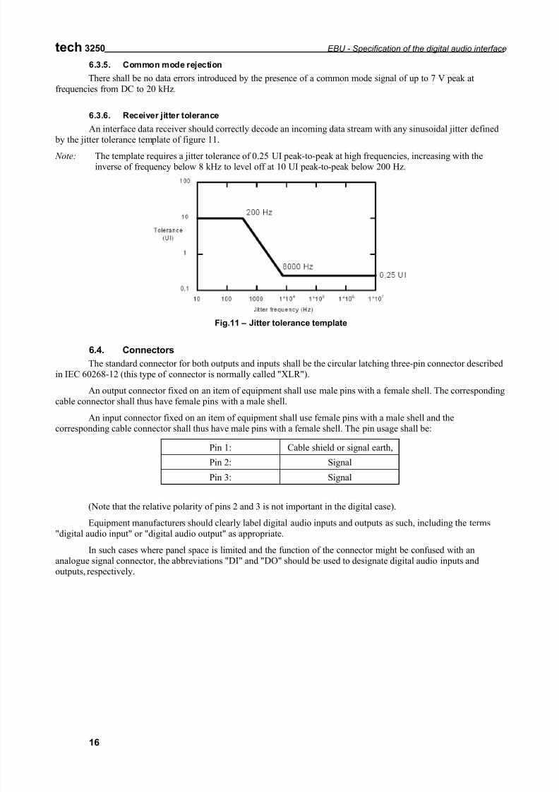
An interface data receiver should correctly decode an incoming data stream with any sinusoidal jitter defined
by the jitter tolerance template of figure 11.
Note: The template requires a jitter tolerance of 0.25 UI peak-to-peak at high frequencies, increasing with theinverse of frequency below 8 kHz to level off at 10 UI peak-to-peak below 200 Hz.
Fig.11 – Jitter tolerance template
6.4. Connectors
The standard connector for both outputs and inputs shall be the circular latching three-pin connector describedin IEC 60268-12 (this type of connector is normally called "XLR").
An output connector fixed on an item of equipment shall use male pins with a female shell. The correspondingcable connector shall thus have female pins with a male shell.
An input connector fixed on an item of equipment shall use female pins with a male shell and thecorresponding cable connector shall thus have male pins with a female shell. The pin usage shall be:
Pin 1: Cable shield or signal earth,
Pin 2: Signal
Pin 3: Signal
(Note that the relative polarity of pins 2 and 3 is not important in the digital case).
Equipment manufacturers should clearly label digital audio inputs and outputs as such, including the terms"digital audio input" or "digital audio output" as appropriate.
In such cases where panel space is limited and the function of the connector might be confused with ananalogue signal connector, the abbreviations "DI" and "DO" should be used to designate digital audio inputs andoutputs, respectively.
7/21/2019 Protocolo AES EBU
http://slidepdf.com/reader/full/protocolo-aes-ebu 17/20
EBU - Specification of the digital audio interface tech 3250
17
Appendix 1
Generation of the CRCC (Byte 23) for channel status
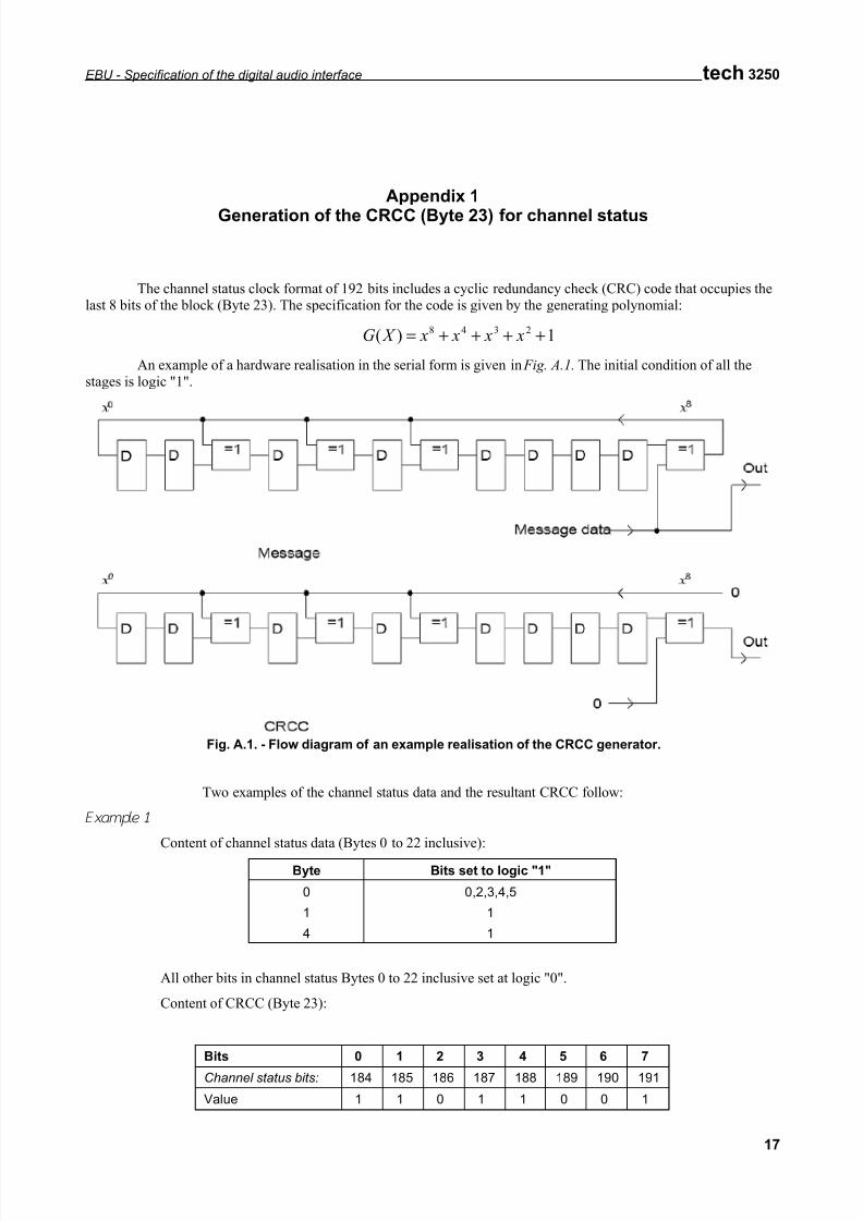
The channel status clock format of 192 bits includes a cyclic redundancy check (CRC) code that occupies thelast 8 bits of the block (Byte 23). The specification for the code is given by the generating polynomial:
1)( 2348++++= x x x x X G
An example of a hardware realisation in the serial form is given in Fig. A.1. The initial condition of all thestages is logic "1".
Fig. A.1. - Flow diagram of an example realisation of the CRCC generator.
Two examples of the channel status data and the resultant CRCC follow:
Example 1
Content of channel status data (Bytes 0 to 22 inclusive):
Byte Bits set to logic "1"
0 0,2,3,4,5
1 1
4 1
All other bits in channel status Bytes 0 to 22 inclusive set at logic "0".
Content of CRCC (Byte 23):
Bits 0 1 2 3 4 5 6 7
Channel status bits: 184 185 186 187 188 189 190 191
Value 1 1 0 1 1 0 0 1
7/21/2019 Protocolo AES EBU
http://slidepdf.com/reader/full/protocolo-aes-ebu 18/20
tech 3250 EBU - Specification of the digital audio interface
18
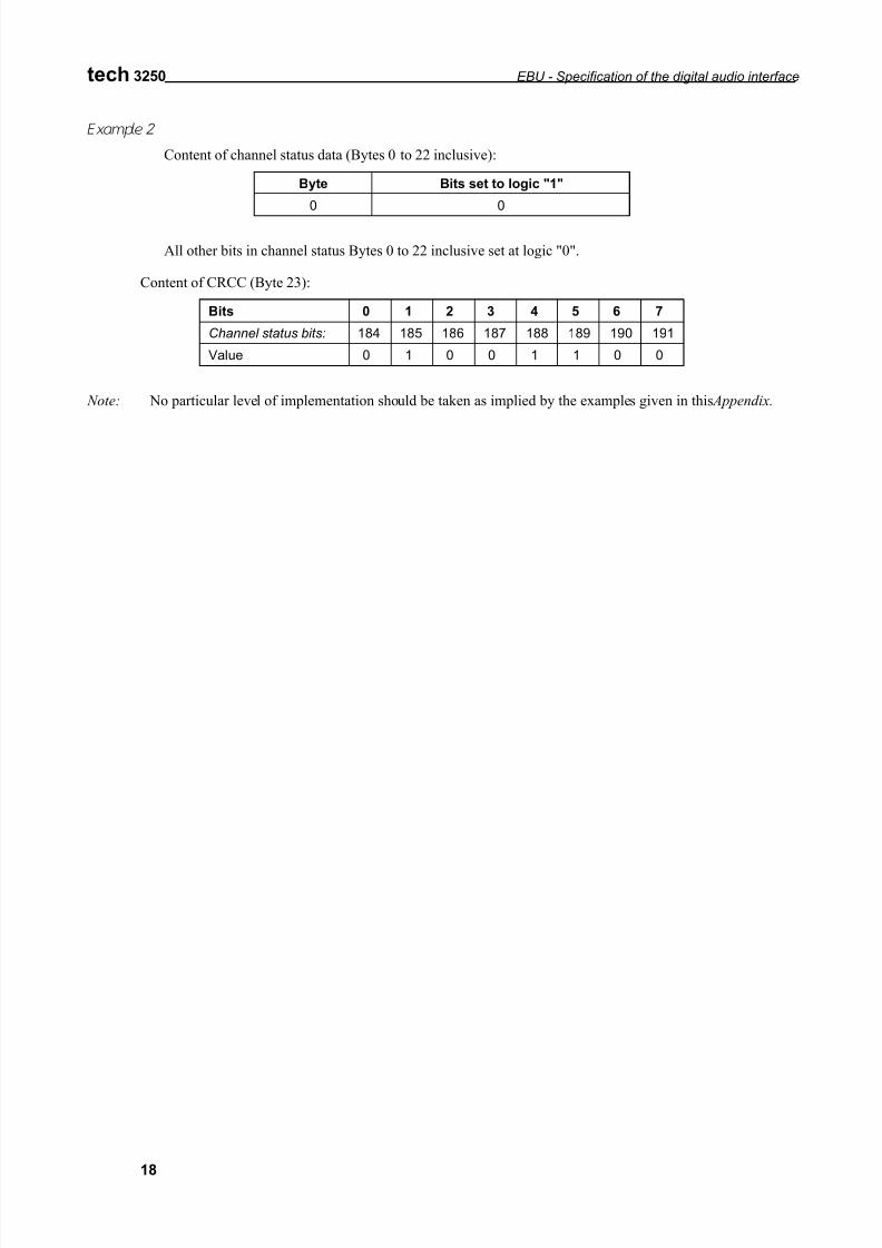
Example 2
Content of channel status data (Bytes 0 to 22 inclusive):
Byte Bits set to logic "1"
0 0
All other bits in channel status Bytes 0 to 22 inclusive set at logic "0".
Content of CRCC (Byte 23):
Bits 0 1 2 3 4 5 6 7
Channel status bits: 184 185 186 187 188 189 190 191
Value 0 1 0 0 1 1 0 0
Note: No particular level of implementation should be taken as implied by the examples given in this Appendix.
7/21/2019 Protocolo AES EBU
http://slidepdf.com/reader/full/protocolo-aes-ebu 19/20
EBU - Specification of the digital audio interface tech 3250
19
Appendix 2
AES/EBU signals on Structured Wiring
There is an increasing use of structured wiring for carrying AES3 signals. Notwithstanding clause 6.1, the practice has been shown to be viable on Category 5 unscreened pairs, meeting EMI requirements, and offeringtransmission up to 400 metres overall unequalised, or 800 metres equalised, at 48 kHz frame rate.
For a satisfactory outcome, this practice should only be used where the whole length of the connection usesCategory 5 UTP (Unscreened Twisted Pair) cable, including that which is installed and any flexible leads (equipment
cords), and that the connection is unscreened for the whole length. Alternatively, the whole length of the connectionshould use Category 5 STP (Screened Twisted Pair), and the connection should be screened for the whole length.
Care should be taken in design of the interface to provide adequate balance on the twisted pair within the Cat.5cable.
Using RJ45 connectors, conventionally wired, current practice favours the use of pins 4 and 5 for AES/EBUsignals (separating them from ATM signals on the same cable). Pins 3 and 6 are the preferred second pair. Note that, for
full protection, the interface may have to withstand power voltages specified to support network equipment, and the useof transformers and blocking capacitors on the AES/EBU interface is strongly recommended.
Suggested practice: while the interface is by definition insensitive to polarity, for the purposes of constructingadaptors, XLR Pin 2 should be connected to RJ45 Pin 5 (or other odd-numbered pin), XLR Pin 3 should be connected
to RJ45 Pin 4 (or even-numbered pin).
7/21/2019 Protocolo AES EBU
http://slidepdf.com/reader/full/protocolo-aes-ebu 20/20
tech 3250 EBU - Specification of the digital audio interface
20
Bibliography
IEC Publication 268-11 (1987): Sound system equipment, Part 11: Application of connectorsfor the interconnection of sound system components.
IEC Publication 268-12 (1987): Sound system equipment Part .12: Application of connectorsfor broadcast and similar use.
ITU-R Recommendation BS647: A digital audio interface for broadcasting studios
IEC Publication 60958-1: Digital audio interface – Part 1: General
IEC Publication 60958-4: Digital audio interface- Part 4: Professional applications.
EBU Technical Recommendation R68-2000: Alignment level in digital audio production equipment and indigital audio recorders
AES11-1991: AES Recommended practice for digital audio engineering -
Synchronization of digital audio equipment in studiooperations.
EBU document Tech. 3250 - Supplement 1, 1992: Format, for the user data channel of the digital audio interface(The AES/EBU interface)
Editeur responsable : Philip Laven, Ancienne Route 17A, CH-1218 Grand-Saconnex / Genève, Suisse.