PEGASO IT-GB - kruba.nl · Standard tool taper ISO 30. Morse di bloccaggio ... Versione 3 e 4 Assi...
8
IT-GB 3-4 Assi Centro di Lavoro 3-4 Axis Machining Centre PEGASO PEGASO
Transcript of PEGASO IT-GB - kruba.nl · Standard tool taper ISO 30. Morse di bloccaggio ... Versione 3 e 4 Assi...
IT-GB
3-4 Assi Centro di Lavoro 3-4 Axis Machining Centre
PEGASOPEGASO

2
Z
XY
A
Centro di lavoro PEGASO 3 e 4 assi a doppia zona di lavoroIl centro di lavoro a contollo numerico PEGASO è stato concepito per la foratura e fresatura di profili di alluminio, acciaio, e leghe leggere. Nella versione a 3 e 4 assi controllati da CNC l’elettromandrino è fornito di cambio utensili automatico, e offre la possibilità di lavorare su 1 o 3 facce del profilo.Il basamento è costituito da un tubo strutturale di grosse dimensioni, sul quale scorre il carro mobile con montante a sbalzo, equipaggiato di elettromandrino e magazzino utensili.
Machining Centre PEGASO 3 and 4 axis with twin operation areaThe maching centre PEGASO has been design for drilling milling and tapping operations on aluminium steel and light steel alloy.Thanks to CNC drive control on 3 and 4 axis version the HSD electro-spindle is able to works on all different radius angulations on the one or three profile surfaces.The basement is made by electtroweled steel supporting the mobile and open bridge carriage including electrospindle and the rack tool device.
3-4 Assi Centro di Lavoro 3-4 Axis Machining Centre
PEGASOPEGASO
I modelli disponibili nella versione standard:
PEGASO
Versione: 3 e 4 assi
P 4000 1 ZONA
P 7000 1 ZONA / 2 ZONE
P 9000 1 ZONA / 2 ZONE
Avaiable standard versions:
PEGASO
Version: 3 and 4 axis
P 4000 1 ZONA
P 7000 1 ZONA / 2 ZONE
P 9000 1 ZONA / 2 ZONE
3
Centro di lavoro - Machining centre
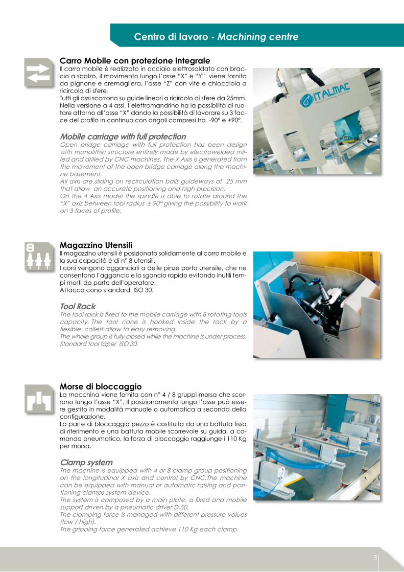
Carro Mobile con protezione integraleIl carro mobile è realizzato in acciaio elettrosaldato con brac-cio a sbalzo, il movimento lungo l’asse “X” e “Y” viene fornito da pignone e cremagliera, l’asse “Z” con vite e chiocciola a ricircolo di sfere. Tutti gli assi scorrono su guide lineari a ricircolo di sfere da 25mm. Nella versione a 4 assi, l’elettromandrino ha la possibilità di ruo-tare attorno all’asse “X” dando la possibilità di lavorare su 3 fac-ce del profilo in continuo con angoli compresi tra -90° e +90°.
Mobile carriage with full protectionOpen bridge carriage with full protection has been design with monolithic structure entirely made by electrowelded mil-led and drilled by CNC machines. The X Axis is generated from the movement of the open bridge carriage along the machi-ne basement.All axis are sliding on recirculation balls guideways of 25 mm that allow an accurate positioning and high precision. On the 4 Axis model the spindle is able to rotate around the “X” axis between tool radius ± 90° giving the possibility to work on 3 faces of profile.
Magazzino UtensiliIl magazzino utensili è posizionato solidamente al carro mobile e la sua capacità è di n° 8 utensili. I coni vengono agganciati a delle pinze porta utensile, che ne consentono l’aggancio e lo sgancio rapido evitando inutili tem-pi morti da parte dell’operatore.Attacco cono standard ISO 30.
Tool Rack The tool rack is fixed to the mobile carriage with 8 rotating tools capacity. The tool cone is hooked inside the rack by a flexible collett allow to easy removing.The whole group is fully closed while the machine is under process. Standard tool taper ISO 30.
Morse di bloccaggioLa macchina viene fornita con n° 4 / 8 gruppi morsa che scor-rono lungo l’asse “X”. Il posizionamento lungo l’asse può esse-re gestito in modalità manuale o automatica a seconda della configurazione. La parte di bloccaggio pezzo è costituita da una battuta fissa di riferimento e una battuta mobile scorrevole su guida, a co-mando pneumatico, la forza di bloccaggio raggiunge i 110 Kg per morsa.
Clamp system The machine is equipped with 4 or 8 clamp group positioning on the longitudinal X axis and control by CNC.The machine can be equipped with manual or automatic raising and posi-tioning clamps system device. The system is composed by a main plate, a fixed and mobile support driven by a pneumatic driver D.50.The clamping force is managed with different pressure values (low / high). The gripping force generated achieve 110 Kg each clamp.
4 5
4 5
4 5
4
3-4 Assi Centro di Lavoro 3-4 Axis Machining Centre
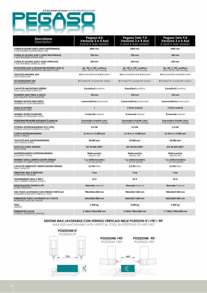
PEGASOPEGASODescrizioneDescription
Pegaso 4.0Versione 3 e 4 Assi3 and 4 Axis version
Pegaso Twin 7.0Versione 3 e 4 Assi3 and 4 Axis version
Pegaso Twin 9.0Versione 3 e 4 Assi3 and 4 Axis version
CORSA DI LAVORO ASSE X (ASSE LONGITUDINALE)X AXE TRAVERSE (LONGITUDINAL AXE)
4000 mm 5000 mm 9000 mm
CORSA DI LAVORO ASSE Y (ASSE TRASVERSALE)Y AXE TRAVERSE (CROSS AXE)
700 mm 700 mm 700 mm
CORSA DI LAVORO ASSE Z (ASSE VERTICALE)Z AXE TRAVERSE (VERTICAL AXE)
230 mm 230 mm 230 mm
ROTAZIONE ASSE A (ROTAZIONE INTORNO ASSE X)A AXE ROTATION (ROTATION AROUND X AXE)
da -90° a +90° continuo from -90° to +90° no stop
da -90° a +90° continuo from -90° to +90° no stop
da -90° a +90° continuo from -90° to +90° no stop
VELOCITÀ MASSIMA ASSIMAX SPEED AXIS
X 80 m/min Y 60 m/min Z 30 m/min X 80 m/min Y 60 m/min Z 30 m/min X 80 m/min Y 60 m/min Z 30 m/min
ACCELERAZIONE ASSIACCELERATION AXIS
X 2 m/sec2 Y 1.6 m/sec2 Z 1 m/sec2 X 2 m/sec2 Y 1.6 m/sec2 Z 1 m/sec2 X 2 m/sec2 Y 1.6 m/sec2 Z 1 m/sec2
CAPACITÀ MAGAZZINO UTENSILITOOL MAGAZINE CAPACITY
8 posizioni/positions 8 posizioni/positions 8 posizioni/positions
DIAMETRO MAX FRESA A DISCOMAX MILLING TOOL DIAMETER
120 mm 120 mm 120 mm
NUMERO BATTUTE ZERO PEZZONUMBER OF STOPS REFERENCE
1 pneumatiche/pneumatic 2 pneumatiche/pneumatic 2 pneumatiche/pneumatic
ZONA DI LAVOROOPERATION AREA
1 2 (Twin system) 2 (Twin system)
NUMERO MORSE STANDARDNUMBER OF STANDARD VICES
4 manuali/manual 8 manuali/manual 8 manuali/manual
POSIZIONATORE MORSE AUTOMATICO (optional)AUTOMATIC VICES POSITIONER (optional)
Pneumatico tramite carroPneumatic by the carriage
Pneumatico tramite carroPneumatic by the carriage
Pneumatico tramite carroPneumatic by the carriage
POTENZA ELETTROMANDRINO IN S1 (STD)SPINDLE MOTOR POWER IN S1 (STD)
5,5 kW 5,5 kW 5,5 kW
COPPIA ELETTROMANDRINORATED TORQUE
3,6 N/m a 12.000 rpm 3,6 N/m a 12.000 rpm 3,6 N/m a 12.000 rpm
VELOCITÀ MAX ELETTROMANDRINOMAX SPINDLE SPEED
24.000 rpm 24.000 rpm 24.000 rpm
ATTACCO CONO UTENSILETOOL TAPER
ISO 30 DIN 69871 ISO 30 DIN 69871 ISO 30 DIN 69871
RAFFREDDAMENTO ELETTROMANDRINOCOOLING SYSTEM
ElettroventolaElectric fan
ElettroventolaElectric fan
ElettroventolaElectric fan
NUMERO UGELLI LUBRIFICAZIONE UTENSILENUMBER OF LUBRICATION TOOL SPRYERS
1 su elettromandrino1 on the spindle
1 su elettromandrino1 on the spindle
1 su elettromandrino1 on the spindle
CAPACITÀ SERBATOIO LUBRIFICAZIONE UTENSILETANK CAPACITY
2,2 litri/litres 2,2 litri/litres 2,2 litri/litres
PRESSIONE ARIA D’ESERCIZIOOPERATING PRESSURE
7 bar 7 bar 7 bar
ASSORBIMENTO MAX A 400 VMAX CURRENT DRAWN AT 400 V
32 A 32 A 32 A
INGRASSAGGIO PATTINI E VITISLIDES GREASING
Manuale/Manual Manuale/Manual Manuale/Manual
DIM. PEZZO LAVORABILE CON UTENSILE VERTICALEWORKPIECE SIZE WITH VERTICAL TOOL
700x230x4.000 mm 700x230x7.000 mm 700x230x9.000 mm
DIMENSIONI PEZZO LAVORABILE SU 3 FACCEWORKPIECE SIZE ON 3 FACES
460x230x4.000 mm 460x230x7.000 mm 460x230x9.000 mm
PESOWEIGHT
2.300 kg 3.200 kg 3.500 kg
DIMENSIONI (LxPxH)OVERALL DIMENSION (DxWxH)
6.100x2.750x2.000 mm 9.100x2.750x2.000 mm 11.100x2.750x2.000 mm
POSIZIONE 0°POSITION 0°
POSIZIONE +90°POSITION +90°
POSIZIONE -90°POSITION -90°
SEZIONE MAX LAVORABILE CON UTENSILE VERTICALE NELLE POSIZIONI 0°/+90°/-90°MAX SIZE MACHINABLE WITH VERTICAL TOOL IN POSTIONS 0°/+90°/-90°

5
Hardware - Software
HardwarePlancia di comando e controllo numericoDedicato all’impiego su macchine utensili e mandrino controllato il control-lo industriale offre le seguenti caratteristiche:
Piattaforma digitale integrata.• Sofisticati algoritmi per il controllo degli assi.• Interfaccia operatore di facile approccio.• Pannello operatore da 17” a colori TFT, tastiera a membrana e override • feed e velocità.Hard disk da 80 GB (minimo).• Linguaggio di programmazione ISO standard.• Ambiente interfaccia Microsoft Windows XP.•
La plancia di comando è situata frontalmente alla macchina, ed è predi-sposta di tutti i comandi operativi per il corretto funzionamento, pannello operatore, pulsati di comando, fungo di emergenza.4 5
SoftwareIl centro di lavoro PEGASO può essere fornito con un software 2D CAD-CAM ITALSOFT.ITALSOFT è un sistema di programmazione per CNC, potente e allo stesso tempo semplice da usare. Tramite l’interfaccia grafica, l’operatore ha la possibilità di creare la geometria del profilo, o importare il DXF, passando poi alla programmazione delle lavorazioni. L’ambiente grafico permette di visualizzare le lavorazioni in ambiente 3D, generando in automatico il pro-gramma ISO da eseguire in macchina. Il sistema è compatibile con Windows 95, Windows 98, Windows XP.
On our Machining Centre PEGASO can be installed the pro-gramming software ITALSOFT CAD-CAM 3D.ITALSOFT can be PC-based or CNC based programming system that is both powerful and friendly user. Thanks to interactive gra-phical user interface allows users to easily access geometry, lo-ading DXF format. With flexible programming methods user can quickly output highly optimized.The software is able to automatic generate ISO code program directly on the machine keyboard. The system is compatible with Windows 95, Windows 98, Windows XP.
4 5
Console group by CNC systemSpecially designed for machining tool industrial control is offering the following futures:
Digital integrated platform.• Sophisticated driver algorithm.• Operator interface for user friendly.• User panel with colour 17” monitor, membrane switchboard and override • feed e speed. Hard disk up to 80 GB. • Operation language ISO standard.• Interface Microsoft Windows XP.•
The mobile console allows the operator to stay in front of the whole working area.Machine’s control and function keys fit in handle mobile and robust structure equipped with mouse and floppy driver.
ITALSOFT
FLYSUITE
6
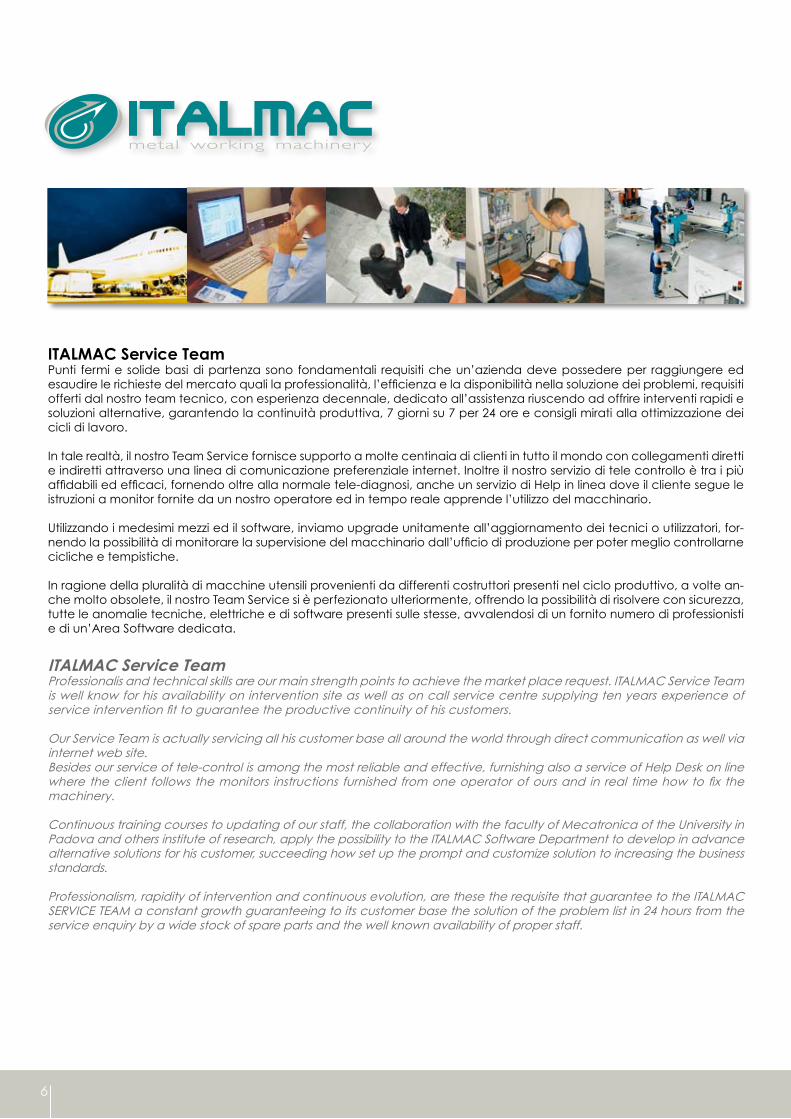
ITALMAC Service TeamPunti fermi e solide basi di partenza sono fondamentali requisiti che un’azienda deve possedere per raggiungere ed esaudire le richieste del mercato quali la professionalità, l’efficienza e la disponibilità nella soluzione dei problemi, requisiti offerti dal nostro team tecnico, con esperienza decennale, dedicato all’assistenza riuscendo ad offrire interventi rapidi e soluzioni alternative, garantendo la continuità produttiva, 7 giorni su 7 per 24 ore e consigli mirati alla ottimizzazione dei cicli di lavoro.
In tale realtà, il nostro Team Service fornisce supporto a molte centinaia di clienti in tutto il mondo con collegamenti diretti e indiretti attraverso una linea di comunicazione preferenziale internet. Inoltre il nostro servizio di tele controllo è tra i più affidabili ed efficaci, fornendo oltre alla normale tele-diagnosi, anche un servizio di Help in linea dove il cliente segue le istruzioni a monitor fornite da un nostro operatore ed in tempo reale apprende l’utilizzo del macchinario.
Utilizzando i medesimi mezzi ed il software, inviamo upgrade unitamente all’aggiornamento dei tecnici o utilizzatori, for-nendo la possibilità di monitorare la supervisione del macchinario dall’ufficio di produzione per poter meglio controllarne cicliche e tempistiche. In ragione della pluralità di macchine utensili provenienti da differenti costruttori presenti nel ciclo produttivo, a volte an-che molto obsolete, il nostro Team Service si è perfezionato ulteriormente, offrendo la possibilità di risolvere con sicurezza, tutte le anomalie tecniche, elettriche e di software presenti sulle stesse, avvalendosi di un fornito numero di professionisti e di un’Area Software dedicata.
ITALMAC Service TeamProfessionalis and technical skills are our main strength points to achieve the market place request. ITALMAC Service Team is well know for his availability on intervention site as well as on call service centre supplying ten years experience of service intervention fit to guarantee the productive continuity of his customers.
Our Service Team is actually servicing all his customer base all around the world through direct communication as well via internet web site.Besides our service of tele-control is among the most reliable and effective, furnishing also a service of Help Desk on line where the client follows the monitors instructions furnished from one operator of ours and in real time how to fix the machinery.
Continuous training courses to updating of our staff, the collaboration with the faculty of Mecatronica of the University in Padova and others institute of research, apply the possibility to the ITALMAC Software Department to develop in advance alternative solutions for his customer, succeeding how set up the prompt and customize solution to increasing the business standards. Professionalism, rapidity of intervention and continuous evolution, are these the requisite that guarantee to the ITALMAC SERVICE TEAM a constant growth guaranteeing to its customer base the solution of the problem list in 24 hours from the service enquiry by a wide stock of spare parts and the well known availability of proper staff.

7
Esempi di campi applicativi che impiegano macchine ITALMAC per la lavorazione di profili di alluminio ed acciaio.
ITALMAC machines are mainly used for processing aluminium and light steel alloys in various application fields.
I dati e le immagini di questo catalogo sono forniti a titolo indicativo, pertanto ITALMAC S.r.l. si riserva il diritto di apportare qualsiasi modifica,per ragioni di natura tecnica o commerciale.
The specifications and illustrations in this catalogue are only a guide, ITALMAC S.r.l. therefore reserves the right to make anymodifications it deems necessary for technical or commercial reasons.
Versione - Version 12/2009
ITALMAC S.r.l. Viale del Lavoro, 137055 Ronco all’Adige (VERONA) ITALY
Tel. +39 045 7000123 Fax +39 045 7000571
e-mail: [email protected]: www.italmac.it