![irp-cdn.multiscreensite.com · MAX FERRO AMMESSO [PPM] MAX MANGANESE AMMESSO [PPM] MAX SALINITÀ [uS/Cm] TEMPERATURA AMBIENTE MINIMAX UMIDITA RELATIVA MAX [0/0] 220VAC - 50Hz 115W](https://static.fdocumenti.com/doc/165x107/6011036cf9c31138be1f8943/irp-cdn-max-ferro-ammesso-ppm-max-manganese-ammesso-ppm-max-salinit-uscm.jpg)
Omt APM110 APM 110 BAR 8vo 16/06/11 16.55 Pagina 1...
68
Filtri - Filters 09 SERIE APM-110 BAR SERIES Filtri in linea a media pressione In line filter medium pressure
Transcript of Omt APM110 APM 110 BAR 8vo 16/06/11 16.55 Pagina 1...

Filtri - Filters
09
SERIE APM-110 BAR SERIES
Filtri in linea a media pressione In line filter medium pressure
Omt_APM110_APM 110 BAR 8vo 16/06/11 16.55 Pagina 1

Versione -Version 01/112010
Con il fine di migliorare costantemente la qualità dei nostri prodotti, ci riserviamo il diritto di modificarne inqualsiasi momento le caratteristiche senza preavviso.È responsabilità della spettabile clientela la costante verifica dei dati contenuti nei cataloghi.Questo catalogo annulla e sostituisce i precedenti.
In order to constantly improve our products quality, we take the right to make changes to the catalogues at anytime without notice.Customers have the responsibility to continuously check all the information in the catalogues.This catalogue cancels and replaces the previous ones.
Omt_APM110_APM 110 BAR 8vo 16/06/11 16.55 Pagina 2

DIMENSIONIDIMENSIONS
1
APM 37
APM 38
60
90
2,4
4,95
TipoType
Portata maxMax delivery
l/min A
Superficie filtrante / Filtration surface dm2 PesoWeight g
2,4
4,95
B
3,14
6,42
C
3,36
6,88
F
3,36
6,88
G
3,36
6,88
H
3,14
6,42
L
3,14
6,42
950
1250
M
C.A. 125
C.A. 250
C.C. 15
C.C. 30
C.C. 50
C.C. 125
5
5
10
5
1
0.5
5
5
10
5
1
0.06
Tensione di aliment.Voltage supply
(V)
Carico resistivoResistive charge
(A)
Carico induttivoInductive charge
(A)
DV500M / DV500
indicatore visivo
Visual indicator
DR500M / DR500
indicatore visivo
con contatti “Reed”
Visual indicator
with “Reed” contacts
DE500M / DE500
indicatore visivo
elettrico
Electrical visual
indicator
Contatti in scambio con i seguenti valoriExchange contacts with the following values:
Gli indicatori visivi sono disponibili:- con filettatura M20x1.5 (DV…M) e filettatura 1/2” BSP (DV…)- con contatti ad ampolla “Reed” (DR131M e DR131)
Visual indicators are available:- with threads M20x1.5 (DV…M) and threads 1/2” BSP (DV…)- with “Reed” contacts (DR131M and DR131)
APM…S
DV500
APM…S + DV500M
DE500
APM…S + DE500M APM…R
DV500
APM…R + DV500M
DE500
APM…R + DE500M
iNDiCAToRi Di iNTASAMENTo / DiffERENTiAl iNDiCAToRS
SiMBologiA / SiMBolS
Omt_APM110_APM 110 BAR 8vo 16/06/11 16.55 Pagina 3
2
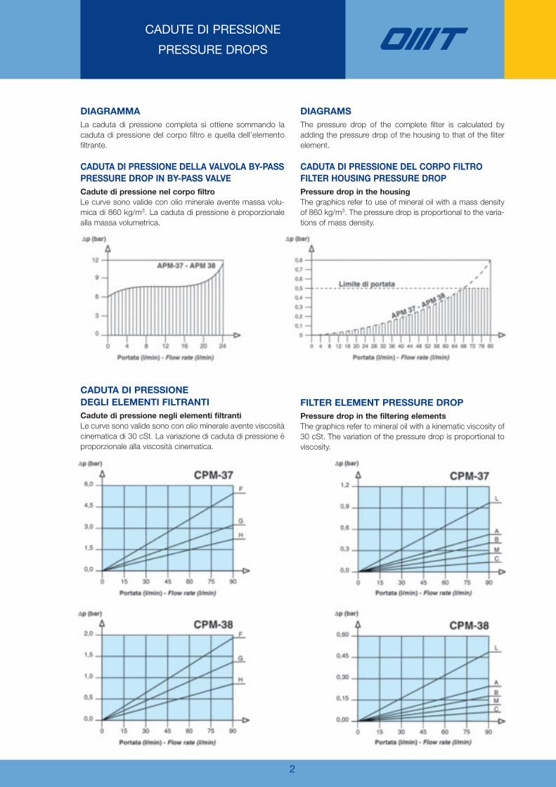
CADUTE DI PRESSIONE
PRESSURE DROPS
CADUTA Di PRESSioNE
DEgli ElEMENTi filTRANTi
Cadute di pressione negli elementi filtranti
Le curve sono valide sono con olio minerale avente viscositàcinematica di 30 cSt. La variazione di caduta di pressione èproporzionale alla viscosità cinematica.
filTER ElEMENT PRESSURE DRoP
Pressure drop in the filtering elements
The graphics refer to mineral oil with a kinematic viscosity of30 cSt. The variation of the pressure drop is proportional toviscosity.
DiAgRAMMA
La caduta di pressione completa si ottiene sommando lacaduta di pressione del corpo filtro e quella dell’elementofiltrante.
CADUTA Di PRESSioNE DEllA VAlVolA BY-PASS
PRESSURE DRoP iN BY-PASS VAlVE
Cadute di pressione nel corpo filtro
Le curve sono valide con olio minerale avente massa volu-mica di 860 kg/m3. La caduta di pressione è proporzionalealla massa volumetrica.
DiAgRAMS
The pressure drop of the complete filter is calculated byadding the pressure drop of the housing to that of the filterelement.
CADUTA Di PRESSioNE DEl CoRPo filTRo
filTER HoUSiNg PRESSURE DRoP
Pressure drop in the housing
The graphics refer to use of mineral oil with a mass densityof 860 kg/m3. The pressure drop is proportional to the varia-tions of mass density.
Omt_APM110_APM 110 BAR 8vo 16/06/11 16.55 Pagina 4
3
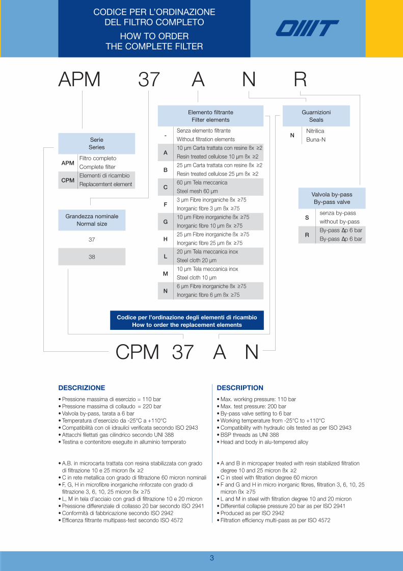
CODICE PER L’ORDINAZIONEDEL FILTRO COMPLETO
HOW TO ORDER THE COMPLETE FILTER
APM 37 A N R
CPM 37 A N
APM
CPM
Filtro completo
Complete filter
Elementi di ricambio
Replacemtent element
SerieSeries
S
R
senza by-pass
without by-pass
By-pass ∆p 6 bar
By-pass ∆p 6 bar
Valvola by-passBy-pass valve
NNitrilica
Buna-N
Guarnizioni Seals
37
38
Grandezza nominaleNormal size
Codice per l’ordinazione degli elementi di ricambio
How to order the replacement elements
-
A
B
C
F
G
H
L
M
N
Senza elemento filtrante
Without filtration elements
10 µm Carta trattata con resine ßx ≥2
Resin treated cellulose 10 µm ßx ≥2
25 µm Carta trattata con resine ßx ≥2
Resin treated cellulose 25 µm ßx ≥2
60 µm Tela meccanica
Steel mesh 60 µm
3 µm Fibre inorganiche ßx ≥75
Inorganic fibre 3 µm ßx ≥75
10 µm Fibre inorganiche ßx ≥75
Inorganic fibre 10 µm ßx ≥75
25 µm Fibre inorganiche ßx ≥75
Inorganic fibre 25 µm ßx ≥75
20 µm Tela meccanica inox
Steel cloth 20 µm
10 µm Tela meccanica inox
Steel cloth 10 µm
6 µm Fibre inorganiche ßx ≥75
Inorganic fibre 6 µm ßx ≥75
Elemento filtranteFilter elements
• Pressione massima di esercizio = 110 bar• Pressione massima di collaudo = 220 bar• Valvola by-pass, tarata a 6 bar• Temperatura d’esercizio da -25°C a +110°C• Compatibilità con oli idraulici verificata secondo ISO 2943• Attacchi filettati gas cilindrico secondo UNI 388• Testina e contenitore eseguite in alluminio temperato
• A.B. in microcarta trattata con resina stabilizzata con grado di filtrazione 10 e 25 micron ßx ≥2 • C in rete metallica con grado di filtrazione 60 micron nominali• F, G, H in microfibre inorganiche rinforzate con grado difiltrazione 3, 6, 10, 25 micron ßx ≥75 • L, M in tela d’acciaio con gradi di filtrazione 10 e 20 micron• Pressione differenziale di collasso 20 bar secondo ISO 2941• Conformità di fabbricazione secondo ISO 2942• Efficenza filtrante multipass-test secondo ISO 4572
•Max. working pressure: 110 bar• Max. test pressure: 200 bar• By-pass valve setting to 6 bar•Working temperature from -25°C to +110°C• Compatibility with hydraulic oils tested as per ISO 2943• BSP threads as UNI 388• Head and body in alu-tempered alloy
• A and B in micropaper treated with resin stabilized filtrationdegree 10 and 25 micron ßx ≥2 • C in steel with filtration degree 60 micron• F and G and H in micro inorganic fibres, filtration 3, 6, 10, 25micron ßx ≥75 • L and M in steel with filtration degree 10 and 20 micron• Differential collapse pressure 20 bar as per ISO 2941• Produced as per ISO 2942• Filtration efficiency multi-pass as per ISO 4572
DESCRizioNE DESCRiPTioN
Omt_APM110_APM 110 BAR 8vo 16/06/11 16.55 Pagina 5

4
NOTES
Omt_APM110_APM 110 BAR 8vo 16/06/11 16.55 Pagina 6

Omt_APM110_APM 110 BAR 8vo 16/06/11 16.55 Pagina 7

OMT s.p.a. Via Lombardia, 14 - 24040 Calvenzano (Bg) ITALY - Tel. +39 0363 860311 - Fax +39 0363 335636www.omtfiltri.com - [email protected]
SCAMBIATORIHEAT EXCHANGERS
FILTRIFILTERS
ACCESSORIACCESSORIES
COMPONENTICOMPONENTS
FLANGE / FLANGESRACCORDI/COUPLINGS BLOCCHI / MANIFOLDS
Filtri - Filters
09
Omt_APM110_APM 110 BAR 8vo 16/06/11 16.55 Pagina 8

SERIE HMM SERIES
Filtri media pressioneMedium pressure filters F
iltri - Filters
04

Versione -Version 04/062018
Con il fine di migliorare costantemente la qualità dei nostri prodotti, ci riserviamo il diritto di modificarne inqualsiasi momento le caratteristiche senza preavviso.È responsabilità della spettabile clientela la costante verifica dei dati contenuti nei cataloghi.Questo catalogo annulla e sostituisce i precedenti.
In order to constantly improve our products quality, we take the right to make changes to the catalogues at anytime without notice.Customers have the responsibility to continuously check all the information in the catalogues.This catalogue cancels and replaces the previous ones.

Tappo di chiusura
Plug
Indicatore visivo
Visual indicator
Indicatore visivo elettrico “Reed”
Visual electrical “Reed” indicator
Indicatore visivo elettrico
Visual electrical indicator
Valvola di by-pass
By-pass valve
Tappo di chiusura
Plug
Testina
Filter head
Guarnizioni
Seals
Elemento filtrante
Filter element
Contenitore
Filter bowl
1
HMM è la serie di filtri per linee in pressione fino a22.000.000 Pa (220 bar-3200 Psi) HMM28,32.000.000 Pa (320 bar-4641 Psi) HMM42; lagamma è composta da due differenti grandezzecon portate nominali fino a 170 L/min. con attacchifilettati o flangiati.Gli elementi filtranti sono costruiti con i più evolutimateriali a garanzia di una elevata efficienza di fil-trazione e della massima durata nel tempo.La concezione di costruzione modulare, propriadella serie HMM, permette al cliente OMT di potersceglierne la configurazione più adatta alle proprienecessità.La divisione Ricerca e Sviluppo presente nella sededi Calvenzano, utilizzando moderne e sofisticateapparecchiature di prova, esercita un costantecontrollo delle prestazioni dei filtri e degli elementifiltranti OMT.
HMM is the medium pressure filter up to22.000.000 Pa (220 bar-3200 Psi) HMM28,32.000.000 Pa (320 bar-4641 Psi) HMM42; therange is composed of two different sizes withnominal flow rates up to 170 l/min. with threadedor flanged connections.Filter elements are made of the most advancedmaterials, as a guarantee for a high filtration effi-ciency and a long-lasting life.HMM series modular construction allows thecustomer to choose the most suitable type follo-wing his needs.OMT Research and Development Department isconstantly check ing filter and elements perfor-mances.
FILTRI MEDIA PRESSIONE SERIE HMM
MEDIUM PRESSURE FILTERS HMM SERIES

2
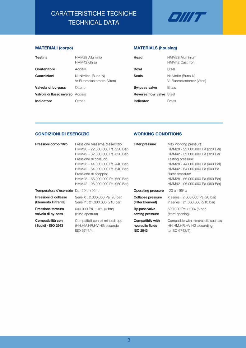
CARATTERISTICHE TECNICHETECHNICAL DATA
LA SERIE DI FILTRI HMM ÈCONFORME ALLE SEGUENTI NORME ISO:
-ISO 2941 - Oleoidraulica - Elementi filtranti - Verifica dellaresistenza allo schiacciamento o allo scoppio
-ISO 2942 - Oleoidraulica - Elementi filtranti - Verificadell’integrità di fabbricazione e determinazionedel punto di prima bolla
-ISO 2943 - Oleoidraulica - Elementi filtranti - Verificadella compatibilità dei materiali con i fluidi
-ISO 3723 - Oleoidraulica - Elementi filtranti - Verifica dellaresistenza alla deformazione assiale
-ISO 3724 - Oleoidraulica - Elementi filtranti - Verifica dellecaratteristiche mediante prova di resistenza afatica in funzione della portata
-ISO 3968 - Oleoidraulica - Filtri - Determinazione della perdita di carico in funzione della portata
-ISO 16889 - Oleoidraulica - Filtri - Metodo Multi-pass:valutazione delle caratteristiche di filtrazionedi un elemento filtrante
MATERIALI (elementi filtranti)
Fondelli Acciaio zincatoTubo di sostegno Acciaio zincatoReti di supporto Acciaio galvanizzato con rivestimento
epossidico
F03 Fibra inorganica / Inorganic fibre Fibra di vetro / Glass fibre 3 3 5F06 Fibra inorganica / Inorganic fibre Fibra di vetro / Glass fibre 6 6 6F10 Fibra inorganica / Inorganic fibre Fibra di vetro / Glass fibre 10 10 9F25 Fibra inorganica / Inorganic fibre Fibra di vetro / Glass fibre 25 25 20T10 Tela / Wire mesh Inox (aisi 304) / Inox (aisi 304) 10 - -T25 Tela / Wire mesh Inox (aisi 304) / Inox (aisi 304) 25 - -C10 Carta trattata / Treaded paper Fibre di cellulosa / Cellulose fibre 10 - -C25 Carta trattata / Treaded paper Fibre di cellulosa / Cellulose fibre 25 - -
Elementi filtrantiFilter elements
DescrizioneDescription
MaterialeMaterial
Grado di filtrazione (µm)Filtration (µm)
Rapporto ß / ß RatioISO 4572ßx≥200
ISO 16889ßx(c)≥200
MATERIALS (filter elements)
Plates Galvanized steelSupport tube Galvanized steelSupport mesh Galvanized steel with epox coating
SETTI FILTRANTI FILTRATION MATERIALS
SUPERFICI UTILI (cm2) ELEMENTI FILTRANTISERIE X - ∆P 2.000.000 Pa (20 bar)
FILTRATION AREA (cm2) FILTER ELEMENTSSERIES X - ∆P 2.000.000 Pa (20 bar)
HMM FILTER SERIES IS SUITABLETO THE FOLLOWING ISO STANDARDS:
-ISO 2941 - Hydraulic fluid power - Filter elementsVerification of collapse / burst resistance
-ISO 2942 - Hydraulic fluid power - Filter elementsVerification of fabrication integrity anddetermination of the first bubble point
-ISO 2943 - Hydraulic fluid power - Filter elementsVerification of material compatibility with fluids
-ISO 3723 - Hydraulic fluid power - Filter elementsMethod for end load test
-ISO 3724 - Hydraulic fluid power - Filter elementsVerification of flow fatigue characteristics
-ISO 3968 - Hydraulic fluid power - Filters - Evaluationof pressure drop versus flow characteristics
-ISO 16889 - Hydraulic fluid power filters - Multi-pass methodfor evaluating filtration performance of afilter element
Elementi filtranti/Filter elements CHP281 CHP282 CHP283 CHP421 CHP422
F03 - F06 - F10 - F25 325 450 870 900 1780T10 - T25 325 450 870 900 1780C10 - C25 325 450 870 900 1780
SUPERFICI UTILI (cm2) ELEMENTI FILTRANTISERIE Y - ∆P 21.000.000 Pa (210 bar)
FILTRATION AREA (cm2) FILTER ELEMENTSSERIES Y - ∆P 21.000.000 Pa (210 bar)
Elementi filtranti/Filter elements CHP281 CHP282 CHP283 CHP421 CHP422
F03 - F06 - F10 - F25 290 410 810 810 1635T10 - T25 290 410 810 810 1635
VALVOLA DI MASSIMA PRESSIONEDIRECT POPPET TYPE RELIEF
3
CARATTERISTICHE TECNICHETECHNICAL DATA
MATERIALI (corpo)
Testina
Contenitore
Guarnizioni
Valvola di by-pass
Valvola di flusso inverso
Indicatore
HMM28 AlluminioHMM42 Ghisa
Acciaio
N: Nitrilica (Buna-N)V: Fluoroelastomero (Viton)
Ottone
Acciaio
Ottone
MATERIALS (housing)
Head
Bowl
Seals
By-pass valve
Reverse flow valve
Indicator
HMM28 AluminiumHMM42 Cast Iron
Steel
N: Nitrilic (Buna-N)V: Fluoroelastomer (Viton)
Brass
Steel
Brass
CONDIZIONI DI ESERCIZIO
Pressioni corpo filtro
Temperatura d'esercizio
Pressioni di collasso(Elemento Filtrante)
Pressione taraturavalvola di by-pass
Compatibilità coni liquidi - ISO 2943
Pressione massima d'esercizio:HMM28 - 22.000.000 Pa (220 Bar)HMM42 - 32.000.000 Pa (320 Bar)Pressione di collaudo:HMM28 - 44.000.000 Pa (440 Bar)HMM42 - 64.000.000 Pa (640 Bar)Pressione di scoppio:HMM28 - 66.000.000 Pa (660 Bar)HMM42 - 96.000.000 Pa (960 Bar)
Da -20 a +95o c
Serie X : 2.000.000 Pa (20 bar)Serie Y : 21.000.000 (210 bar)
600.000 Pa ±10% (6 bar)(inizio apertura)
Compatibili con oli minerali tipo(HH,HM,HR,HV,HG secondoISO 6743/4)
WORKING CONDITIONS
Filter pressure
Operating pressure
Collapse pressure(Filter Element)
By-pass valvesetting pressure
Compatibily withhydraulic fluidsISO 2943
Max working pressure:HMM28 - 22.000.000 Pa (220 Bar)HMM42 - 32.000.000 Pa (320 BarTesting pressure:HMM28 - 44.000.000 Pa (440 Bar)HMM42 - 64.000.000 Pa (640 BaBurst pressure:HMM28 - 66.000.000 Pa (660 Bar)HMM42 - 96.000.000 Pa (960 Bar)
-20 a +95o c
X series : 2.000.000 Pa (20 bar)Y series : 21.000.000 (210 bar)
600.000 Pa ±10% (6 bar)(from opening)
Compatible with mineral oils such asHH,HM,HR,HV,HG accordingto ISO 6743/4)

4
HMM series 28
Le portate sono state calcolate per avere una per-dita di carico ∆p ≤ 120.000 Pa (1.2 bar) con oliominerale avente viscosità cinematica 30 cSt e den-sità 860 kg/m3. (vedi note a pag. 06/07)
Flows have been calculated just in order to obtaina pressure drop ∆p ≤ 120.000 Pa (1.2 bar) withmineral oil kinematic viscosity 30 cSt and 860kg/m3 density. (See remarks on page 06/07)
12345
1/2” BSP3/4” BSP1/2” NPT3/4” NPT
SAE8 - 3/4”-16UNFSAE12 - 1 1/16”- 12UN
M 8M 8
5/16” UNC5/16” UNC5/16” UNC5/16” UNC
Tipo / Type A E (prof. 15mm)E (depth 15mm)
PORTATE CONSIGLIATERECOMMENDED FLOWS
(Elementi in microfibra)(Glass fibre elements)
ATTACCHI FILETTATITHREADED CONNECTIONS
ATA
43
H10
0
ø70
E
46
87
CH 30
10 13.5
68
ø8.5
30
40
43.5
43.5
1/2”
BS
P
123
187214310
HMM281..HMM282..HMM283..
Tipo / Type H (mm) Lunghezza OMT/PallLength OMT/Pall
281281281281282282282282283283283283
F03F06F10F25F03F06F10F25F03F06F10F25
HMM
ElementofiltranteReplaceelement
172035502640558038507095
Portata (L/min)serie X
Flow (L/min)X series
151833472229507032406085
Portata (L/min)serie Y
Flow (L/min)Y series
2,652,652,652,653,23,23,23,24,74,74,74,7
Peso (Kg)Weight (Kg)
LUNGHEZZELENGTHS
CH 30
A
113111113
94
ø78
125
H
47
E
57
10
ø8.5
40
50.5
51.5
1/2 ”
BS
P
33
IM
G
5
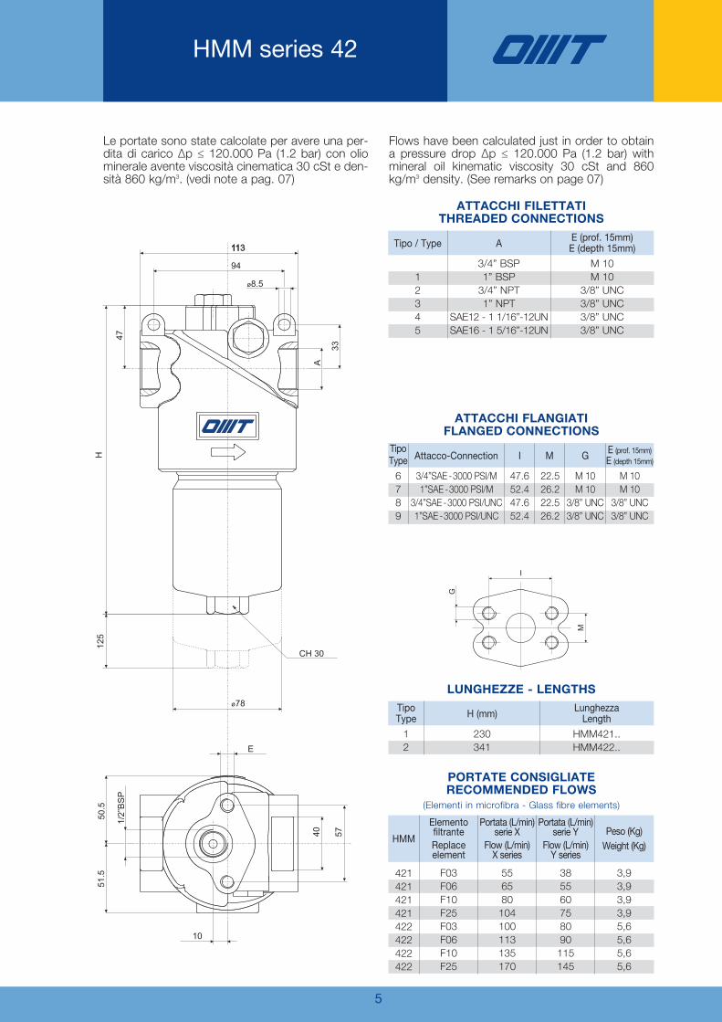
HMM series 42
Le portate sono state calcolate per avere una per-dita di carico ∆p ≤ 120.000 Pa (1.2 bar) con oliominerale avente viscosità cinematica 30 cSt e den-sità 860 kg/m3. (vedi note a pag. 07)
Flows have been calculated just in order to obtaina pressure drop ∆p ≤ 120.000 Pa (1.2 bar) withmineral oil kinematic viscosity 30 cSt and 860kg/m3 density. (See remarks on page 07)
12345
3/4” BSP1” BSP
3/4” NPT1” NPT
SAE12 - 1 1/16”-12UNSAE16 - 1 5/16”-12UN
M 10M 10
3/8” UNC3/8” UNC3/8” UNC3/8” UNC
Tipo / Type A E (prof. 15mm)E (depth 15mm)
PORTATE CONSIGLIATERECOMMENDED FLOWS
(Elementi in microfibra - Glass fibre elements)
ATTACCHI FILETTATITHREADED CONNECTIONS
6789
3/4”SAE -3000 PSI/M1”SAE -3000 PSI/M
3/4”SAE -3000 PSI/UNC1”SAE -3000 PSI/UNC
M 10M 10
3/8” UNC3/8” UNC
M 10M 10
3/8” UNC3/8” UNC
22.526.222.526.2
47.652.447.652.4
Tipo Type Attacco-Connection I M G E (prof. 15mm)
E (depth 15mm)
ATTACCHI FLANGIATIFLANGED CONNECTIONS
12
230341
HMM421..HMM422..
TipoType H (mm) Lunghezza
Length
421421421421422422422422
F03F06F10F25F03F06F10F25
HMM
ElementofiltranteReplaceelement
556580104100113135170
Portata (L/min)serie X
Flow (L/min)X series
385560758090
115145
Portata (L/min)serie Y
Flow (L/min)Y series
3,93,93,93,95,65,65,65,6
Peso (Kg)Weight (Kg)
LUNGHEZZE - LENGTHS

6
Cadute di Pressione(conformi a ISO 3968)
Pressure Drops(according to ISO 3968)
La caduta di pressione completa si ottiene som-mando la caduta di pressione del corpo filtro equella dell’elemento filtrante.Cadute di pressione nel corpo filtroLe curve sono valide con olio minerale aventemassa volumica di 860 Kg/m3.La caduta di pressione è proporzionale alla massavolumica.Cadute di pressione negli elementi filtrantiLe curve sono valide con olio minerale aventeviscosità cinematica di 30 cSt.La variazione di caduta di pressione è proporziona-le alla viscosità cinematica.
The pressure drop of the complete filter is calculatedby adding the pressure drop of the housing to thatof the filter element.Pressure drops in the housingsThe graphics refer to use of mineral oil with a massdensity of 860 Kg/m3.The pressure drop is proportional to the variations ofmass density.Pressure drops in the filter elementsThe graphics refer to mineral oil with a kinematicviscosity of 30 cSt. The variation of the pressuredrop is proportional to viscosity.
0
10
20
30
40
50
60
0 20 40 60 80 100
portata / flow (L/min)
del
taP
(KP
a )
0
300
600
900
1200
0 10 20 30 40 50
portata /flow (L/min)
del
taP
(KP
a)
0
140
120
100
80
60
40
20
160
180
200
0 10 20 30 40 50 60
portata / flow (L/min)
del
taP
(KP
a)
0F3 6
F0 F01
5F2
0
20
40
60
80
100
120
140
160
180
200
0 20 3010 40 50 7060 80 90 100
portata / flow (L/min)
del
taP
(KP
a)
F03
F06 1F
0
25F
0
140
120
100
80
60
40
20
160
180
200
0 10 20 30 40 50 60
portata / flow (L/min)
del
taP
(KP
a)
F03 06F
01F
F 52
0
20
40
60
80
100
120
140
160
180
200
0 20 3010 40 50 7060 80 90 100
portata / flow (L/min)
del
taP
(KP
a)
F03
F60 F
01
F25
∆P CORPI / ∆P HOUSINGS BY-PASS / BY-PASS
∆P ELEMENTI X / ∆P X ELEMENTS ∆P ELEMENTI Y / ∆P Y ELEMENTStipo 281 series
∆P ELEMENTI X / ∆P X ELEMENTS ∆P ELEMENTI Y / ∆P Y ELEMENTStipo 282 series
HMM serie/series 28

0
140
120
100
80
60
40
20
160
180
200
0 20 40 60 80 100 120
portata / flow (L/min)
del
taP
(KP
a)
F03
F06 10F
25F
0
140
120
100
80
60
40
20
160
180
200
0 20 40 60 80 100 120
portata / flow (L/min)
del
taP
(KP
a)
F30 F06 0
F1
F25
7
0
140
120
100
80
60
40
20
160
180
200
0 20 40 60 80 100 120 140
portata / flow (L/min)
del
taP
(KP
a)
03F6
F0 F01
F 52
0
140
120
100
80
60
40
20
160
180
200
0 20 40 60 80 100 120 140
portata / flow (L/min)
del
taP
(KP
a)
F30 F06
F01
25F
0
20
40
60
80
100
120
140
160
180
200
0 20 40 60 80 100 120 140 160 180
portata / flow (L/min)
del
taP
(KP
a)
3F0 06
F
0F1
25F
0
20
40
60
80
100
120
140
160
180
200
0 20 40 60 80 100 120 140 160 180
portata / flow (L/min)
del
taP
(KP
a)
F30 06
F 0F1
5F2
Cadute di Pressione(conformi a ISO 3968)
Pressure Drops(according to ISO 3968)
∆P ELEMENTI X / ∆P X ELEMENTS ∆P ELEMENTI Y / ∆P Y ELEMENTStipo 421 series
∆P ELEMENTI X / ∆P X ELEMENTS ∆P ELEMENTI Y / ∆P Y ELEMENTStipo 283 series
∆P ELEMENTI X / ∆P X ELEMENTS ∆P ELEMENTI Y / ∆P Y ELEMENTS
∆P CORPI / ∆P HOUSINGS BY-PASS / BY-PASS RF FLUSSO INV. / REV. FLOW VALVE
tipo 422 series
HMM serie/series 42
0
10
20
30
40
50
60
70
80
0 20 40 60 80 100 120 140 160 180 200portata / flow (L/min)
del
taP
(KP
a)
Con valvolaReverse flow
0
400
200
800
600
1200
1000
1600
1400
0 20 40 60 80 100portata / flow (L/min)
del
taP
(KP
a)
0
100
200
300
400
500
600
0 20 40 60 80 100portata / flow (L/min)
del
taP
(KP
a)

8
VALVOLA DI FLUSSO INVERSO
REVERSE FLOW VALVE
INGRESSOIN
USCITAOUT
Disponibile per i modelli HMM:421 - 422
Available for HMM models:421 - 422

9
INDICATORI DIFFERENZIALI
DIFFERENTIAL INDICATORS
CH 30
70
ø16
45
®
1/2” BSP
CH 30
4228
ø16
®
1/2” BSP
®
1/2” BSP
ø16
CH 30
HMM...S/P HMM...S/P + DV800 HMM...S/P + DE800/DR800
B B
A AN.A.
N.C.
C
B
A
3/bl
2/
1
N.A.
N.C.
C
HMM...R/Q HMM...R/Q + DV500 HMM...R/Q + DE500/DR500
B B
A A
B
A
2/
1
brma
3/blbrma
C
INDICATORE VISIVOVISUAL INDICATOR
INDICATORE VISIVO-ELETTRICOELECTRICAL VISUAL INDICATOR
INDICATORE VISIVO-ELETTRICOCON CONTATTI “REED”
VISUAL-ELECTRICAL INDICATORWITH “REED” CONTACTS
CARATTERISTICHE TECNICHETECHNICAL DATA
SIMBOLOGIA / SIMBOLOGYCon By-pass / With By-pass Senza By-pass / Without By-pass
CodicePart
number
DescrizioneDescription
TaraturaSetting
ContattielettriciElectricalContacts
ApplicazioneApplication
Tensioni di rottura per “DR 500 e DR 800”Breakdown voltage for “DR 500 and DR 800”
Tensione di alimen. (V)Feeder voltage (V)
Potenza con carico induttivo (VA)Power with inductive load (VA)
A.C. 3-115D.C. 3-115
2020
D V 500 visivo - visual
elettrico - electrical
visivo- elettricocon contatti “reed”
Visual-electricalwith “reed” contacts
500.000Pa(5 bar) Scambio
Switch
-Filtri con By-pass
ed elementifiltranti serie “X”
Filters with By-passand elements
“X” series
D E 500
D R 500
D V 800 visivo - visual
elettrico - electrical
visivo- elettricocon contatti “reed”
Visual-electricalwith “reed” contacts
D E 800
D R 800
800.000Pa(8 bar) Scambio
Switch
-Filtri con By-pass
ed elementifiltranti serie “Y”
Filters with By-passand elements
“Y” series
Tensioni di rottura per “DE 500 e DE 800”Breakdown voltage for “DE 500 and DE 800”
Tensione di alimen. (V)Feeder voltage (V)
Carico resistivo (A)Resistive load (A)
Carico induttivo (A)Inductive load (A)
A.C. 125A.C. 250D.C. 15D.C. 30D.C. 50
D.C. 125
551052
0.5
55
1052
0.06
DV500/800 DE500/800 DR500/800
10
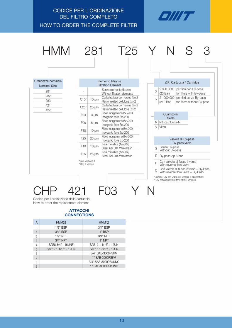
CODICE PER L’ORDINAZIONEDEL FILTRO COMPLETO
HOW TO ORDER THE COMPLETE FILTER
HMM 281 T25 Y N S 3
CHP 421 F03 Y N
Grandezza nominaleNominal Size
281282283421422
-123456789
Elemento filtranteFiltration Element
A HMM28
1/2” BSP3/4” BSP1/2” NPT3/4” NPT
SAE8 3/4” - 16UNFSAE12 1 1/16” - 12UN
3/4” BSP1” BSP3/4” NPT1” NPT
SAE12 1 1/16” - 12UNSAE16 1 5/16” - 12UN3/4” SAE-3000PSI/M1” SAE-3000PSI/M
3/4” SAE-3000PSI/UNC1” SAE-3000PSI/UNC
HMM42
-
C10*
C25*
F03
F06
F10
F25
T10
T25
10 µm
25 µm
3 µm
6 µm
10 µm
25 µm
10 µm
25 µm
Senza elemento filtranteWithout filtration elementsCarta trattata con resine ßx>2Resin treated cellulose ßx>2Carta trattata con resine ßx>2Resin treated cellulose ßx>2Fibre inorganiche ßx>200Inorganic fibre ßx>200Fibre inorganiche ßx>200Inorganic fibre ßx>200Fibre inorganiche ßx>200Inorganic fibre ßx>200Fibre inorganiche ßx>200Inorganic fibre ßx>200Tela metallica (Aisi304)Steel Aisi 304 Wire meshTela metallica (Aisi304)Steel Aisi 304 Wire mesh
GuarnizioniSeals
NV
S
R
P
Q
Nitrica / Buna-NViton
∆P. Cartuccia / Cartridge
X
Y
2.000.000(20 Bar)21.000.000(210 Bar)
per filtri con By-passfor filters with By-passper filtri senza By-passfor filters without By-pass
Valvola di By-passBy-pass valve
Senza By-passWithout By-pass
By-pass ∆p 6 bar
Con valvola di flusso inversoWith reverse flow valveCon valvola di flusso inverso + By-PassWith reverse flow valve + By-Pass
Codice per l'ordinazione della cartucciaHow to order the replacement element
ATTACCHICONNECTIONS
*Solo versione X*Only X version
*Opzioni P, Q non valide per versioni di tipo HMM28*P, Q options not valid for HMM28 versions

11
NOTES

12
NOTES


OMT S.p.A. Via Lombardia, 14 - 24040 Calvenzano (Bg) ITALY - Tel. +39 0363 860311 - Fax +39 0363 335636www.omtfiltri.com - [email protected]
SCAMBIATORIHEAT EXCHANGERS
FILTRIFILTERS
ACCESSORIACCESSORIES
COMPONENTICOMPONENTS
FLANGE/FLANGESRACCORDI/COUPLINGS BLOCCHI/MANIFOLDS
Filtri - Filters
04
ACCUMULATORIACCUMULATOR

SERIE HPB - 315 BAR SERIES
Filtri alta pressioneHigh pressure filters
Filtri - Filters
10
Omt_HPB_OMT hpb 02/10/13 12.20 Pagina 1

Versione -Version 02/102013
Con il fine di migliorare costantemente la qualità dei nostri prodotti, ci riserviamo il diritto di modificarne inqualsiasi momento le caratteristiche senza preavviso.È responsabilità della spettabile clientela la costante verifica dei dati contenuti nei cataloghi.Questo catalogo annulla e sostituisce i precedenti.
In order to constantly improve our products quality, we take the right to make changes to the catalogues at anytime without notice.Customers have the responsibility to continuously check all the information in the catalogues.This catalogue cancels and replaces the previous ones.
Omt_HPB_OMT hpb 02/10/13 12.20 Pagina 2

DIMENSIONIDIMENSIONS
1
TESTiNA CoN ATTACCo CEToP 05
HEAD wiTH CoNNECTioN CEToP 05
TESTiNA CoN ATTACCo CEToP 03
HEAD wiTH CoNNECTioN CEToP 03
HPB 061
HPB 282
HPB 283
CETOP 03
CETOP 05
CETOP 05
150
172
272
CodiceCode
AttaccoConnection A
231,5
281,5
381,5
B
M20x1.5
1/2” BSP
C
C.A. 125
C.A. 250
C.C. 15
C.C. 30
C.C. 50
C.C. 125
5
5
10
5
1
0.5
5
5
10
5
1
0.06
Tensione di aliment.Voltage supply
(V)
Carico resistivoResistive charge
(A)
Carico induttivoInductive charge
(A)
DV500M / DV500
indicatore visivo
elettrico
Electrical visual
indicator
DR500M / DR500
indicatore visivo
con contatti “Reed”
Visual indicator
with “Reed” contacts
DE500M / DE500
indicatore visivo
Visual indicator
Contatti in scambio con i seguenti valoriExchange contacts with the followings values:
Gli indicatori visivi sono disponibili:- con filettatura M20x1.5 (DV…M) e filettatura 1/2” BSP (DV…)- con contatti ad ampolla “Reed” (DR500M e DR500)
Visual indicators are available:- with threads M20x1.5 (DV…M) and threads 1/2” BSP (DV…)- with “Reed” contacts (DR500M and DR500)
iNDiCAToRi Di iNTASAMENTo / DiffERENTiAl iNDiCAToRS
SiMBologiA / SiMBolS
HPBDV500
HPB + DV500M DE500
HPB + DE500M
Omt_HPB_OMT hpb 02/10/13 12.20 Pagina 3
2
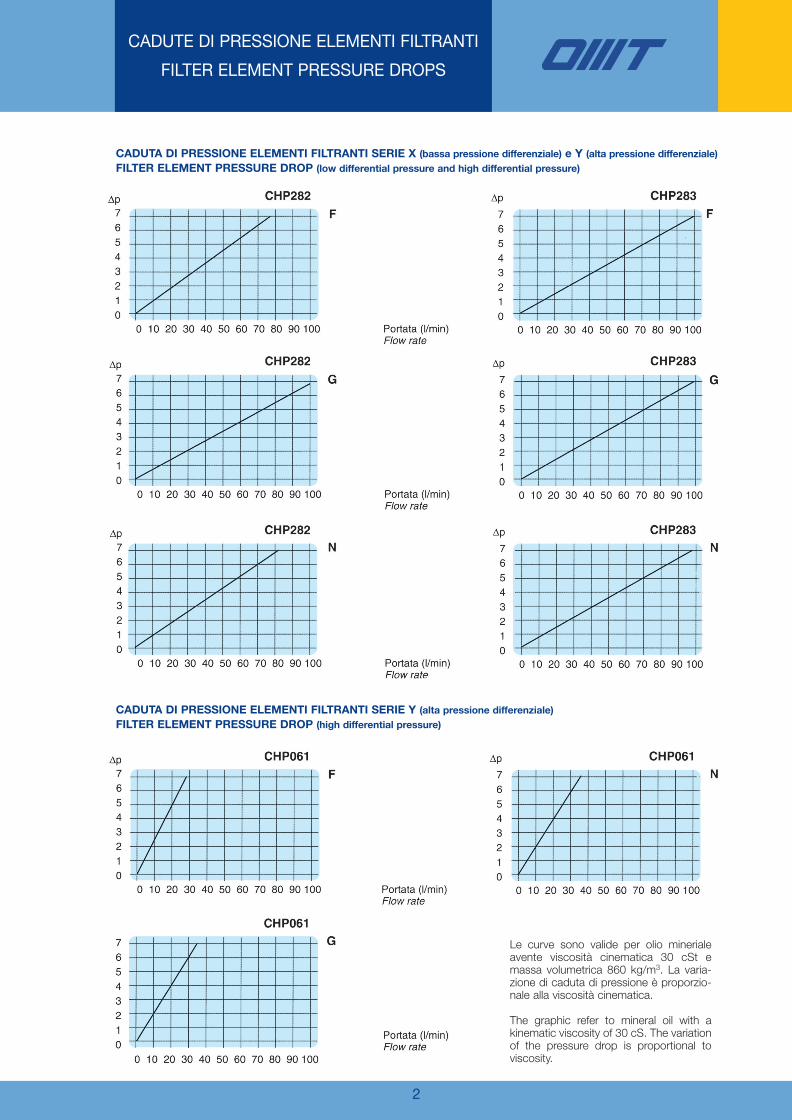
CADUTE DI PRESSIONE ELEMENTI FILTRANTI
FILTER ELEMENT PRESSURE DROPS
CADuTA Di PRESSioNE ElEMENTi filTRANTi SERiE X (bassa pressione differenziale) e Y (alta pressione differenziale)
filTER ElEMENT PRESSuRE DRoP (low differential pressure and high differential pressure)
CADuTA Di PRESSioNE ElEMENTi filTRANTi SERiE Y (alta pressione differenziale)
filTER ElEMENT PRESSuRE DRoP (high differential pressure)
Le curve sono valide per olio minerialeavente viscosità cinematica 30 cSt emassa volumetrica 860 kg/m3. La varia-zione di caduta di pressione è proporzio-nale alla viscosità cinematica.
The graphic refer to mineral oil with akinematic viscosity of 30 cS. The variationof the pressure drop is proportional toviscosity.
Omt_HPB_OMT hpb 02/10/13 12.20 Pagina 4

3
CODICE PER L’ORDINAZIONEDEL FILTRO COMPLETO
HOW TO ORDER THE COMPLETE FILTER
HPB 061 F Y N -
CHP 061 F Y N
HPB
CHP
Filtro completo
Complete filter
Elementi filtranti
Filter elements
SerieSeries
X
Y
20 Bar
210 Bar
*Cartucce serie CHP061, solo versione “Y”*Cartridges type CHP061 only model “Y”
∅ p. Elemento filtranteFilter elements
-
G
M20 x1,5
1/2” BSP
FilettatureThread
N
V
Nitrilica
Buna-N
Viton
Guarnizioni Seals
061
282
283
Lunghezza unica
Only one leinght
Lunghezza 1
Leinght 1
Lunghezza 2
Leinght 2
Grandezza nominaleNormal size
Codice per l’ordinazione degli elementi filtranti
How to order the replacement elements
-
F
G
N
Senza elemento filtrante
Without filtration elements
3 µm Fibre inorganiche ßx ≥75
Inorganic fibre 3 µm ßx ≥75
10 µm Fibre inorganiche ßx ≥75
Inorganic fibre 10 µm ßx ≥75
6 µm Fibre inorganiche ßx ≥75
Inorganic fibre 6 µm ßx ≥75
Elemento filtranteFilter elements
filtri per alte pressioni
DATi TECNiCi filTRo CoMPlETo
- Testa fusa in ghisa sferoidale- Contenitore in acciaio- Pressione massima di esercizio 315 bar- Pressione di prova a fatica da 0 a 300 bar e per 1.000.000 di cicli- Pressione di collaudo 450 bar- Pressione di collasso 900 bar- Pressione d’esercizio -20 +95 °C
ElEMENTi filTRANTi
- iSo 4572 - Oleoidraulica - Filtri - Determinazione del grado di filtrazione- iSo 2942 - Oleoidraulica - Elementi filtranti - Verifica della conformità difabbricazione
- iSo 2943 - Oleoidraulica - Elementi filtranti - Verifica della compatibilitàdei materiali con oli minerali (tipo HH - HM - HR - HV - HG secondo ISO 6743/4)
- iSo 3723 - Oleoidraulica - Elementi filtranti - Verifica della resistenza alladeformazione assiale
- iSo 3724 - Oleoidraulica - Elementi filtranti - Verifica della resistenza afatica per variazioni di portata
- iSo 2941 - Oleoidraulica - Elementi filtranti - Verifica della resistenza alloschiacciamento (collasso)
- iSo 3968 Ci.B. - Oleoidraulica - Filtri - Determinazione della perdita dicarico in funzione della portata
High pressure filters
TECHNiCAl DATA
- Filter head melts in cast spheroidal iron- Steel housing- Max working pressure 315 bar- Fatigue pressure of 1.000.000 cycles at 0-300 bar- Static pressure testing at 450 bar- Collapse pressure 900 bar- Operating temperature -20 +95 °C
filTRATioN ElEMENTS
- iSo 4572 - Hydraulic fluid power - Filters - Multi-pass method for eva-luating filtration performance
- iSo 2942 - Hydraulic fluid power - Filters elements - Verification of fabri-cation integrity and determination of first bubble point
- iSo 2943 - Hydraulic fluid power - Filters elements - Verification ofmaterial compatibility with fluids (HH - HM - HR - HV - HG type accor-ding ISO 6743/4)
- iSo 3723 - Hydraulic fluid power - Filters elements - Method for endload test
- iSo 3724 - Hydraulic fluid power - Filters elements - Verification of flowfatigue characteristics
- iSo 2941 - Hydraulic fluid power - Filters elements - Verification of col-lapse/burst resistance
- iSo 3968 Ci.B. - Hydraulic fluid power - Filters - Evaluation of pressuredrop versus flow characteristics
DESCRizioNE DESCRiPTioN
*** solo per elementi filtranti serie 28i riferimenti diventanoonly for filter elements series 28the references becomeF - F03G - F10N - F06
***
Omt_HPB_OMT hpb 02/10/13 12.20 Pagina 5

4
NOTES
Omt_HPB_OMT hpb 02/10/13 12.20 Pagina 6

Omt_HPB_OMT hpb 02/10/13 12.20 Pagina 7

OMT s.p.a. Via Lombardia, 14 - 24040 Calvenzano (Bg) ITALY - Tel. +39 0363 860311 - Fax +39 0363 335636www.omtfiltri.com - [email protected]
SCAMBIATORIHEAT EXCHANGERS
FILTRIFILTERS
ACCESSORIACCESSORIES
COMPONENTICOMPONENTS
FLANGE / FLANGESRACCORDI/COUPLINGS BLOCCHI /MANIFOLDS
8
Filtri - Filters
10
Omt_HPB_OMT hpb 02/10/13 12.24 Pagina 8
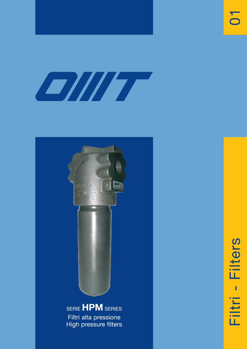
SERIE HPM SERIES
Filtri alta pressioneHigh pressure filters F
iltri - Filters
01

Versione -Version 05/042018
Con il fine di migliorare costantemente la qualità dei nostri prodotti, ci riserviamo il diritto di modificarne inqualsiasi momento le caratteristiche senza preavviso.È responsabilità della spettabile clientela la costante verifica dei dati contenuti nei cataloghi.Questo catalogo annulla e sostituisce i precedenti.
In order to constantly improve our products quality, we take the right to make changes to the catalogues at anytime without notice.Customers have the responsibility to continuously check all the information in the catalogues.This catalogue cancels and replaces the previous ones.

FILTRI ALTA PRESSIONE SERIE HPM42.000.000 Pa (420 BAR)
HIGH PRESSURE FILTERS HPM SERIES42.000.000 Pa (420 BAR)
Tappo di chiusura
Plug
Indicatore visivo
Visual indicator
Indicatore visivo elettrico “Reed”
Visual el. “Reed” indicator
Indicatore visivo elettrico
Visual el. indicator
Valvola di by-pass
By-pass valve
Ta ppo di chiusura
PlugTestina
Filter head
Guarnizioni
Seals
Elemento filtrante
Filter element
Contenitore
Filter bowl
1
HPM è la serie di filtri per linee in pressione fino a42.000.000 Pa (420bar-6000Psi); la gamma è com-posta da tre differenti grandezze con portate nomi-nali fino a 400L/min, ed attacchi filettati o flangiati.Gli elementi filtranti sono costruiti con i più evolutimateriali, a garanzia di una elevata efficienza di fil-trazione e della massima durata nel tempo.La concezione di costruzione modulare, propriadella serie HPM, permette al cliente OMT di potersceglierne la configurazione più adatta alla proprianecessità.La divisione Ricerca e Sviluppo presente nella sededi Calvenzano, utilizzando moderne e sofisticateapparecchiature di prova, esercita un costantecontrollo delle prestazioni dei filtri e degli elementifiltranti OMT.
HPM is the high pressure filter up to 42.000.000 Pa(420 bar-6000 Psi); the range is composed by 3 dif-ferent sizes with nominal flow rates up to 400 l/min.,available with threaded or flanged connections.Filter elements are made with the most advancedmaterials, as a guarantee for an high filtration effi-ciency and a long-lasting life.HPM series modular construction allows thecustomer to choose the most suitable type follo-wing his needs.OMT Research & Development Department isconstantly making a check about filter and ele-ments performances.

2
CARATTERISTICHE TECNICHETECHNICAL DATA
LA SERIE DI FILTRI HPM ÈCONFORME ALLE SEGUENTI NORME ISO:
-ISO 2941 - Oleoidraulica - Elementi filtranti - Verificadella resistenza allo schiacciamento o allo scoppio
-ISO 2942 - Oleoidraulica - Elementi filtranti - Verificadell’integrità di fabbricazione e determinazionedel punto di prima bolla
-ISO 2943 - Oleoidraulica - Elementi filtranti - Verificadella compatibilità dei materiali con i fluidi
-ISO 3723 - Oleoidraulica - Elementi filtranti - Verificadella resistenza alla deformazione assiale
-ISO 3724 - Oleoidraulica - Elementi filtranti - Verificadelle caratteristiche mediante prova di resistenzaa fatica in funzione della portata
-ISO 3968 - Oleoidraulica - Filtri - Determinazione dellaperdita di carico in funzione della portata
-ISO 16889 - Oleoidraulica - Filtri - Metodo Multi-pass valutazione delle caratteristiche di filtrazione di un elemento filtrante
MATERIALI (elementi filtranti)
Fondelli Acciaio zincatoTubo di sostegno Acciaio zincatoReti di supporto Acciaio galvanizzato con rivestimento
epossidico
F03 Fibra inorganica / Inorganic fibre Fibra di vetro / Glass fibre 3 3 5 F06 Fibra inorganica / Inorganic fibre Fibra di vetro / Glass fibre 6 6 6 F10 Fibra inorganica / Inorganic fibre Fibra di vetro / Glass fibre 10 10 9 F25 Fibra inorganica / Inorganic fibre Fibra di vetro / Glass fibre 25 25 20 T10 Tela / Wire mesh Inox (aisi 304) / Inox (aisi 304) 10 - - T25 Tela / Wire mesh Inox (aisi 304) / Inox (aisi 304) 25 - - C10 Carta trattata / Treaded paper Fibre di cellulosa / Cellulose fibre 10 - - C25 Carta trattata / Treaded paper Fibre di cellulosa / Cellulose fibre 25 - -
Elementi filtrantiFilter elements
DescrizioneDescription
MaterialeMaterial
Grado di filtrazione (µm)Filtration (µm)
Rapporto ß / ß RatioISO 4572ßx≥200
ISO 16889ßx(c)≥200
MATERIALS (filter elements)
Plates Galvanized steelSupport tube Galvanized steelSupport mesh Galvanized steel with epox coating
SETTI FILTRANTI FILTRATION MATERIALS
SUPERFICI UTILI (cm2) ELEMENTI FILTRANTISERIE X - ∆P 2.000.000 Pa (20 bar)
FILTRATION AREA (cm2) FILTER ELEMENTSSERIES X - ∆P 2.000.000 Pa (20 bar)
HPM FILTER SERIES IS SUITABLETO THE FOLLOWING ISO STANDARDS:
-ISO 2941 - Hydraulic fluid power - Filter elementsVerification of collapse / burst resistance
-ISO 2942 - Hydraulic fluid power - Filter elementsVerification of fabrication integrity anddetermination of the first bubble point
-ISO 2943 - Hydraulic fluid power - Filter elementsVerification of material compatibility with fluids
-ISO 3723 - Hydraulic fluid power - Filter elementsMethod for end load test
-ISO 3724 - Hydraulic fluid power - Filter elementsVerification of flow fatigue characteristics
-ISO 3968 - Hydraulic fluid power - Filters - Evaluationof pressure drop versus flow characteristics
-ISO 16889 - Hydraulic fluid power - Filters - Multi-pass methodfor evaluating filtration performance of afilter element
Elementi filtranti/Filter elements CHP281 CHP282 CHP283 CHP421 CHP422 CHP621 CHP622 CHP623 CHP624
F03 - F06 - F10 - F25 325 450 870 900 1780 1500 3070 4920 6770 T10 - T25 325 450 870 900 1780 1500 3070 4920 6770 C10 - C25 325 450 870 900 1780 1500 3070 4920 6770
SUPERFICI UTILI (cm2) ELEMENTI FILTRANTISERIE Y - ∆P 21.000.000 Pa (210 bar)
FILTRATION AREA (cm2) FILTER ELEMENTSSERIES Y - ∆P 21.000.000 Pa (210 bar)
Elementi filtranti/Filter elements CHP281 CHP282 CHP283 CHP421 CHP422 CHP621 CHP622 CHP623 CHP624
F03 - F06 - F10 - F25 290 410 810 810 1635 960 2015 3245 4480 T10 - T25 290 410 810 810 1635 960 2015 3245 4480

VS-30
VALVOLA DI MASSIMA PRESSIONEDIRECT POPPET TYPE RELIEF
3
CARATTERISTICHE TECNICHETECHNICAL DATA
MATERIALI (corpo)
Testina
Contenitore
Guarnizioni
Valvola di by-pass
Valvola di flusso inverso
Indicatore
Ghisa
Acciaio o ghisa
N: Nitrilica (Buna-N)V: Fluoroelastomero(viton)
Ottone
Acciaio
Ottone
MATERIALS (housing)
Head
Bowl
Seals
By-pass valve
Reverse flow valve
Indicator
Cast iron
Steel or cast iron
N: Buna-NV: Viton
Brass
Steel
Brass
CONDIZIONI DI ESERCIZIO
Pressioni corpo filtro
Temperatura d'esercizio
Pressioni di collasso
Pressione taraturavalvola di by-pass
Compatibilità coni liquidi - ISO 2943
Pressione massima d'esercizio:42.000.000 Pa (420 bar)Pressione di collaudo:63.000.000 Pa (630 bar)Pressione di scoppio:126.000.000 Pa (1260 bar)
Da -20 a +95o c
Serie X : 2.000.000 Pa (20 bar)Serie Y : 21.000.000 (210 bar)
6 bar ±10% (inizio apertura)
Compatibili con oli minerali tipo(HH,HM,HR,HV,HG secondo ISO6743/4)
WORKING CONDITIONS
Filter pressure
Operating pressure
Collapse pressure
By-pass valvesetting pressure
Compatibily withhydraulic fluidsISO 2943
Working pressure:42.000.000 Pa (420 bar)Testing pressure:63.000.000 Pa (630 bar)Collapse pressure:126.000.000 Pa (1260 bar)
-20 a +95o c
X series : 2.000.000 Pa (20 bar)Y series : 21.000.000 (210 bar)
6 bar ±10% (from opening)
Compatible with mineral oils such asHH,HM,HR,HV,HG accordingto ISO 6743/4)

4
HPM series 28
Le portate sono state calcolate per ottenere unaperdita di carico ∆p ≤ 120.000 Pa (1.2 bar) con oliominerale avente viscosità cinematica 30 cst e den-sità 860 kg/m3. (vedi note a pag. 08-09 )
Flows have been calculated just in order to obtaina pressure drop ∆p ≤ 120.000 Pa (1.2 bar) Withmineral oil kinematic viscosity 30 cst and 860kg/m3 density. (See remarks on page 08-09)
1234567
1/2” BSP3/4” BSP1/2” NPT3/4” NPT
SAE8 - 3/4”-16UNFSAE12 - 1 1/16”- 12UN
1/2” BSPT3/4” BSPT
M 8M 8
5/16” UNC5/16” UNC5/16” UNC5/16” UNC
M 8M 8
Tipo / Type A E (prof. 15mm)E (depth 15mm)
PORTATE CONSIGLIATERECOMMENDED FLOWS
(Elementi in microfibra)(Glass fibre elements)
ATTACCHI FILETTATITHREADED CONNECTIONS
H
45 A
85
46
E
ø70
CH30
100
13,510
123
189214310
HPM281..HPM282..HPM283..
Tipo / Type H (mm) Lunghezza OMT/PallLength OMT/Pall
281281281281282282282282283283283283
F03F06F10F25F03F06F10F25F03F06F10F25
HPM
ElementofiltranteReplaceelement
172035502640558038507095
Portata (L/min)serie X
Flow (L/min)X series
151833472229507032406085
Portata (L/min)serie Y
Flow (L/min)Y series
3,83,83,83,84,24,24,24,26666
Peso (Kg)Weight (Kg)
LUNGHEZZELENGTHS
H
45
110
A57
E
ø78CH30
125
30
M
G
I
5
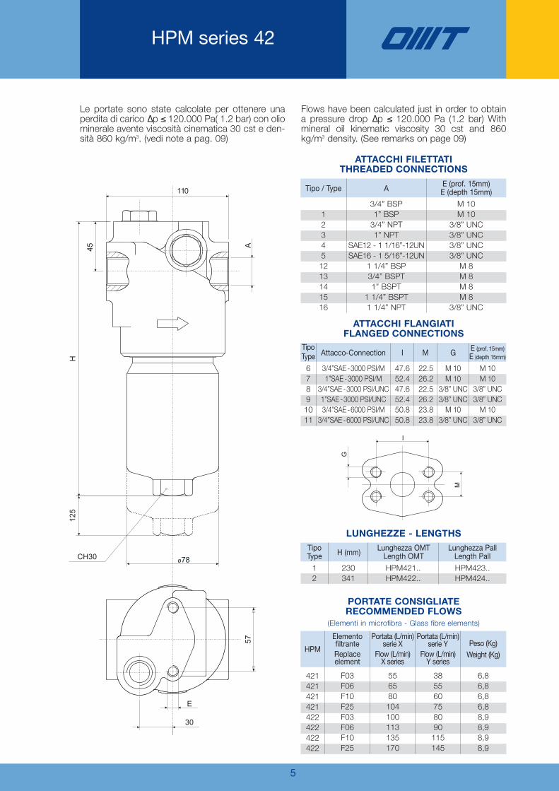
HPM series 42
Le portate sono state calcolate per ottenere unaperdita di carico ∆p ≤ 120.000 Pa( 1.2 bar) con oliominerale avente viscosità cinematica 30 cst e den-sità 860 kg/m3. (vedi note a pag. 09)
Flows have been calculated just in order to obtaina pressure drop ∆p ≤ 120.000 Pa (1.2 bar) Withmineral oil kinematic viscosity 30 cst and 860kg/m3 density. (See remarks on page 09)
123451213141516
3/4” BSP1” BSP3/4” NPT1” NPT
SAE12 - 1 1/16”-12UNSAE16 - 1 5/16”-12UN
1 1/4” BSP3/4” BSPT1” BSPT
1 1/4” BSPT1 1/4” NPT
M 10M 10
3/8” UNC3/8” UNC3/8” UNC3/8” UNCM 8M 8M 8M 8
3/8” UNC
Tipo / Type A E (prof. 15mm)E (depth 15mm)
PORTATE CONSIGLIATERECOMMENDED FLOWS
(Elementi in microfibra - Glass fibre elements)
ATTACCHI FILETTATITHREADED CONNECTIONS
67891011
3/4”SAE -3000 PSI/M1”SAE -3000 PSI/M
3/4”SAE -3000 PSI/UNC1”SAE -3000 PSI/UNC3/4”SAE -6000 PSI/M3/4”SAE -6000 PSI/UNC
M 10M 10
3/8” UNC3/8” UNCM 10
3/8” UNC
M 10M 10
3/8” UNC3/8” UNCM 10
3/8” UNC
22.526.222.526.223.823.8
47.652.447.652.450.850.8
Tipo Type Attacco-Connection I M G E (prof. 15mm)
E (depth 15mm)
ATTACCHI FLANGIATIFLANGED CONNECTIONS
12
230341
HPM423..HPM424..
TipoType H (mm) Lunghezza Pall
Length Pall
HPM421..HPM422..
Lunghezza OMTLength OMT
421421421421422422422422
F03F06F10F25F03F06F10F25
HPM
ElementofiltranteReplaceelement
556580104100113135170
Portata (L/min)serie X
Flow (L/min)X series
385560758090115145
Portata (L/min)serie Y
Flow (L/min)Y series
6,86,86,86,88,98,98,98,9
Peso (Kg)Weight (Kg)
LUNGHEZZE - LENGTHS

6
HPM series 62
le portate sono state calcolate per ottenere unaperdita di carico ∆p ≤ 120.000 Pa ( 1.2 bar) con oliominerale avente viscosità cinematica 30 cst e den-sità 860 kg/m3. (vedi note a pag. 10)
Flows have been calculated just in order to obtaina lpressure drop ∆p ≤ 120.000 Pa (1.2 bar) Withmineral oil kinematic viscosity 30 cst and 860kg/m3 density. (See remarks on page 10)
62
140
A
H
ø110
150
CH30
E
57
94
15
G
M
I
1234567141516
1” BSP1 1/4” BSP1 1/2” BSP1” NPT
1 1/4” NPT1 1/2” NPT
SAE20 - 1 5/8” - 12UNSAE24 - 1 7/8” - 12UN
1” BSPT1 1/4” BSPT1 1/2” BSPT
M 12M 12M 12
1/2” UNC1/2” UNC1/2” UNC1/2” UNC1/2” UNCM 12M 12M 12
Tipo / Type A E (prof. 15mm)E (depth 15mm)
PORTATE CONSIGLIATERECOMMENDED FLOWS
(Elementi in microfibra - Glass fibre elements)
ATTACCHI FILETTATITHREADED CONNECTIONS
8910111213
1 1/4” SAE - 3000PSI/M1 1/2” SAE - 3000 PSI/M1 1/4” SAE - 3000 PSI/UNC1 1/2” SAE - 3000 PSI/UNC1 1/4” SAE - 6000 PSI/M1 1/4” SAE - 3000 PSI/UNC
M 12M 12
1/2” UNC1/2” UNCM 12
1/2” UNC
M 10M 10
7/16” UNC1/2” UNCM 14
1/2” UNC
30.235.730.235.731.631.6
58.77058.77066.766.7
Tipo Type Attacco-Connection I M G E (prof. 15mm)
E (depth 15mm)
ATTACCHI FLANGIATIFLANGED CONNECTIONS
1234
273393533673
HPM625..HPM626..HPM627..HPM628..
TipoType H (mm) Lunghezza Pall
Length Pall
HPM621..HPM622..HPM623..HPM624..
Lunghezza OMTLength OMT
621621621621622622622622623623623623624624624624
F03F06F10F25F03F06F10F25F03F06F10F25F03F06F10F25
HPM
ElementofiltranteReplaceelement
110125145190206250300345250290330375285330360410
Portata (L/min)serie X
Flow (L/min)X series
7080105155145180220245225260290365240265310345
Portata (L/min)serie Y
Flow (L/min)Y series
1313131316,716,716,716,720,520,520,520,524242424
Peso (Kg)Weight (Kg)
LUNGHEZZE - LENGTHS

7
Gli elementi filtranti OMT serie CHP sono perfetta-mente intercambiabili con gli elementi filtranti “Pall”,come indicato nella tabella:
OMT replace elements CHP Series are perfectlyinterchangeable with “Pall” replace elements, asindicated in the following table:
Indicando la grandezza dell’elemento filtrante OMTnel codice di ordinazione, i filtri completi serie HPMsaranno forniti con l’elemento filtrante e codolospeciale intercambiabile “Pall”
Esempio: HPM 628 F03XNR
Filtro completo OMT serie HPM62 con elemento fil-trante intercambiabile al tipo “Pall HC9600FKP16H”
HPM complete filters will be supplied with thereplace element and special interchangeable “Pall”tang, if when ordering the OMT replace element,you indicate the size of the replace element in thecomplete part-number.
Example: HPM 628 F03XNR
Complete OMT filter series HPM62 with replaceelement interchangeable to “Pall HC9600FKP16H”
VALVOLA DI FLUSSO INVERSO
REVERSE FLOW VALVE
Disponibile per i modelli HPM:421 - 422 - 621 - 622 - 623 - 624
Available for HPM models:421 - 422 - 621 - 622 - 623 - 624
INGRESSOIN
USCITAOUT
Codice “Pall”Pall part-number
Codice OMTOMT part-number
ELEMENTI FILTRANTI INTERCAMBIABILI “PALL”FILTER ELEMENTS INTERCHANGEABLE TO “PALL”
HC9020 FKP4H FKN4H FKS4H FKT4H HC9020 FKP8H FKN8H FKS8H FKT8H HC9021 FDP4H FDT4H HC9021 FDP8H FDT8H HC9800 FKP4H FKN4H FKS4H FKT4H
CHP282 F03XN F06XN F10XN F25XN CHP283 F03XN F06XN F10XN F25XN CHP282 F03YN F10YN CHP283 F03YN F10YN CHP423 F03XN F06XN F10XN F25XN
Codice “Pall”Pall part-number
Codice OMTOMT part-number
HC9800 FKP8H FKN8H FKS8H FKT8H HC9801 FDP4H FDT4H HC9801 FDP8H FDT8H HC9600 FKP4H FKN4H FKS4H FKT4H HC9600 FKP8H FKN8H FKS8H FKT8H
CHP424 F03XN F06XN F10XN F25XN CHP423 F03YN F10YN CHP424 F03YN F10YN CHP625 F03XN F06XN F10XN F25XN CHP626 F03XN F06XN F10XN F25XN
Codice “Pall”Pall part-number
Codice OMTOMT part-number
HC9600 FKP13H FKN13H FKS13H FKT13H HC9600 FKP16H FKN16H FKS16H FKT16H HC9601 FDP4H FDT4H HC9601 FDP8H FDT8H HC9601 FDP13H FDT13H HC9601 FDP16H FDT16H
CHP627 F03XN F06XN F10XN F25XN CHP628 F03XN F06XN F10XN F25XN CHP625 F03YN F10YN CHP626 F03YN F10YN CHP627 F03YN F10YN CHP628 F03YN F10YN
FILTRO COMPLETO - COMPLETE FILTER

8
Cadute di Pressione(conformi a ISO 3968)
Pressure Drops(according to ISO 3968)
La caduta di pressione completa si ottiene som-mando la caduta di pressione del corpo filtro equella dell’elemento filtrante.Cadute di pressione nel corpo filtroLe curve sono valide con olio minerale aventemassa volumica di 860 Kg/m3.La caduta di pressione è proporzionale alla massavolumica.Cadute di pressione negli elementi filtrantiLe curve sono valide con olio minerale aventeviscosità cinematica di 30 cSt.La variazione di caduta di pressione è proporziona-le alla viscosità cinematica.
The pressure drop of the complete filter is calculatedby adding the pressure drop of the housing to that ofthe filter element.Pressure drops in the housingsThe graphics refer to use of mineral oil with a massdensity of 860 Kg/m3.The pressure drop is proportional to the variations ofmass density.Pressure drops in the filter elementsThe graphics refer to mineral oil with a kinematicviscosity of 30 cSt. The variation of the pressuredrop is proportional to viscosity.
0
10
20
30
40
50
60
0 20 40 60 80 100
portata / flow (L/min)
del
taP
(KP
a)
0
300
600
900
1200
0 10 20 30 40 50
portata /flow (L/min)
del
taP
(KP
a)
0
140
120
100
80
60
40
20
160
180
200
0 10 20 30 40 50 60
portata / flow (L/min)
del
taP
(KP
a)
F03
F06 F1
0
F25
0
20
40
60
80
100
120
140
160
180
200
0 20 3010 40 50 7060 80 90 100
portata / flow (L/min)
del
taP
(KP
a)
F03
F06
F10
F25
0
140
120
100
80
60
40
20
160
180
200
0 10 20 30 40 50 60
portata / flow (L/min)
del
taP
(KP
a)
F03
F06
F10
F25
0
20
40
60
80
100
120
140
160
180
200
0 20 3010 40 50 7060 80 90 100
portata / flow (L/min)
del
taP
(KP
a )
F03
F06
F10
F25
∆P CORPI / ∆P HOUSINGS BY-PASS / BY-PASS
∆P ELEMENTI X / ∆P X ELEMENTS ∆P ELEMENTI Y / ∆P Y ELEMENTStipo 281 series
∆P ELEMENTI X / ∆P X ELEMENTS ∆P ELEMENTI Y / ∆P Y ELEMENTStipo 282 series
HPM serie/series 28

0
140
120
100
80
60
40
20
160
180
200
0 20 40 60 80 100 120 140
portata / flow (L/min)
del
taP
(KP
a )
F03 F06F10
F25
0
20
40
60
80
100
120
140
160
180
200
0 20 40 60 80 100 120 140 160 180
portata / flow (L/min)
del
taP
(KP
a)
F03F06
F10
F25
0
140
120
100
80
60
40
20
160
180
200
0 20 40 60 80 100 120 140
portata / flow (L/min)
del
taP
(KP
a)
F03
F06F10 F25
0
20
40
60
80
100
120
140
160
180
200
0 20 40 60 80 100 120 140 160 180
portata / flow (L/min)
del
taP
(KP
a )
F03F06
F10
F25
0
140
120
100
80
60
40
20
160
180
200
0 20 40 60 80 100 120
portata / flow (L/min)
del
taP
(KP
a)
F03
F06 F10
F25
0
140
120
100
80
60
40
20
160
180
200
0 20 40 60 80 100 120
portata / flow (L/min)
del
taP
(KP
a)
F03
F06 F10
F25
0
10
20
30
40
50
60
70
80
0 20 40 60 80 100 120 140 160 180 200portata / flow (L/min)
del
taP
(KP
a )
Con valvolaReverse flow
0
400
200
800
600
1200
1000
1600
1400
0 20 40 60 80 100portata / flow (L/min)
del
taP
(KP
a)
0
100
200
300
400
500
600
0 20 40 60 80 100portata / flow (L/min)
del
taP
(KP
a)
9
Cadute di Pressione(conformi a ISO 3968)
Pressure Drops(according to ISO 3968)
∆P ELEMENTI X / ∆P X ELEMENTS ∆P ELEMENTI Y / ∆P Y ELEMENTStipo 421 series
∆P ELEMENTI X / ∆P X ELEMENTS ∆P ELEMENTI Y / ∆P Y ELEMENTStipo 283 series
∆P CORPI / ∆P HOUSINGS BY-PASS / BY-PASS RF FLUSSO INV. / REV. FLOW VALVE
∆P ELEMENTI X / ∆P X ELEMENTS ∆P ELEMENTI Y / ∆P Y ELEMENTStipo 422 series
HPM serie/series 42

10
Cadute di Pressione(conformi a ISO 3968)
Pressure Drops(according to ISO 3968)
0
10
20
30
40
50
60
70
80
90
0 50 100 150 200 250 300 350 400 450portata / flow (L/min)
del
taP
(KP
a )
0
200
400
600
800
1000
1200
0 50 100 150 200 250portata / flow (L/min)
del
taP
(KP
a)0
100
200
300
400
500
600
0 50 100 150 200portata / flow (L/min)
del
taP
(KP
a)
0
140
120
100
80
60
40
20
160
180
200
0 40 80 120 160 200 240
portata / flow (L/min)
del
taP
(KP
a)
F03
F06 F1
0
F25
0
20
40
60
80
100
120
140
160
180
200
0 80 12040 160 200 280240 320 360 400
portata / flow (L/min)
del
taP
(KP
a)
F03 F0
6
F10
F25
0
140
120
100
80
60
40
20
160
180
200
0 40 80 120 160 200 240 280 320 360 400 440
portata / flow (L/min)
del
taP
(KP
a )
F03
F06
F10
F25
0
140
120
100
80
60
40
20
160
180
200
0 40 80 120 160 200 240 280 320 360 400 440
portata / flow (L/min)
del
taP
(KP
a )
F03
F06
F10
F25
0
140
120
100
80
60
40
20
160
180
200
0 40 80 120 160 200 240
portata / flow (L/min)d
elta
P(K
Pa)
F03
F06
F10
F25
0
20
40
60
80
100
120
140
160
180
200
0 80 12040 160 200 280240 320 360 400
portata / flow (L/min)
del
taP
(KP
a)
F03
F06
F10
F25
0
140
120
100
80
60
40
20
160
180
200
0 40 80 120 160 200 240 280 320 360 400 440
portata / flow (L/min)
del
taP
(KP
a)
F03
F06
F10
F25
0
140
120
100
80
60
40
20
160
180
200
0 40 80 120 160 200 240 280 320 360 400 440
portata / flow (L/min)
del
taP
(KP
a)
F03 F0
6
F10
F25
HPM serie/series 62
∆P ELEMENTI X / ∆P X ELEMENTS ∆P ELEMENTI Y / ∆P Y ELEMENTStipo 621 series
∆P ELEMENTI X / ∆P X ELEMENTS ∆P ELEMENTI Y / ∆P Y ELEMENTStipo 622 seriestipo 622 series
∆P ELEMENTI X / ∆P X ELEMENTS ∆P ELEMENTI Y / ∆P Y ELEMENTStipo 623 series
∆P ELEMENTI X / ∆P X ELEMENTS ∆P ELEMENTI Y / ∆P Y ELEMENTStipo 624 series
∆P CORPI / ∆P HOUSINGS BY-PASS / BY-PASS RF FLUSSO INV. / REV. FLOW VALVE

11
INDICATORI DIFFERENZIALI
DIFFERENTIAL INDICATORS
CH 30
70
ø16
45
CH 30
ø16
®
1/2” BSP
CH 30
4228
ø16
®
1/2” BSP
®
1/2” BSP
HPM...S/P HPM...S/P + DV800 HPM...S/P + DE800 / DR800
B B
A AN.A.
N.C.
C
B
A
3/bl
2/
1/
N.A.
N.C.
C
HPM...R/Q HPM...R/Q + DV500 HPM...R/Q + DE500 / DR500
B B
A A
B
A
brma
bkne
3/bl
2/
1/
brma
bkne
C
INDICATORE VISIVOVISUAL INDICATOR
INDICATORE VISIVO-ELETTRICOELECTRICAL VISUAL INDICATOR
INDICATORE VISIVO-ELETTRICOCON CONTATTI “REED”
VISUAL-ELECTRICAL INDICATORWITH “REED” CONTACTS
CARATTERISTICHE TECNICHETECHNICAL DATA
SIMBOLOGIA / SIMBOLOGYCon By-pass / With By-pass Senza By-pass / Without By-pass
CodicePart
number
DescrizioneDescription
TaraturaSetting
ContattielettriciElectricalContacts
ApplicazioneApplication
Tensioni di rottura per “DR 500 e DR 800”Breakdown voltage for “DR 500 and DR 800”
Tensione di alimen. (V)Feeder voltage (V)
Potenza con carico induttivo (VA)Power with inductive load (VA)
A.C. 3-115D.C. 3-115
2020
D V 500 visivo - visual
elettrico - electrical
visivo- elettricocon contatti “reed”Visual-electrical
with “reed” contacts
500.000Pa(5 bar) Scambio
Switch
-Filtri con By-passed elementi
filtranti serie “X”Filters with By-passand elements“X” series
D E 500
D R 500
D V 800 visivo - visual
elettrico - electrical
visivo- elettricocon contatti “reed”Visual-electrical
with “reed” contacts
D E 800
D R 800
800.000Pa(8 bar) Scambio
Switch
-Filtri con By-passed elementi
filtranti serie “Y”Filters with By-passand elements“Y” series
Tensioni di rottura per “DE 500 e DE 800”Breakdown voltage for “DE 500 and DE 800”
Tensione di alimen. (V)Feeder voltage (V)
Carico resistivo (A)Resistive load (A)
Carico induttivo (A)Inductive load (A)
A.C. 125A.C. 250D.C. 15D.C. 30
55105
55105
DV500/800 DE500/800 DR500/800

12
CODICE PER L’ORDINAZIONEDEL FILTRO COMPLETO
HOW TO ORDER THE COMPLETE FILTER
HPM 283 F10 X N R 2
CHP 421 F03 Y N
Grandezza nominaleNominal Size
281282283
421 - (423 Pall)422 - (424 Pall)621 - (625 Pall)622 - (626 Pall)623 - (627 Pall)624 - (628 Pall)
-12345678910111213141516
Elemento filtranteFiltration Element
A HPM28
1/2” BSP3/4” BSP1/2” NPT3/4” NPT
SAE8 3/4” - 16UNFSAE 12
1/2” BSPT3/4” BSPT
3/4” BSP1” BSP3/4” NPT1” NPT
SAE12 1 1/16” - 12UNSAE16 1 5/16” - 12UN3/4” SAE-300PSI/M1” SAE-3000PSI/M
3/4” SAE-300PSI/UNC1” SAE-3000PSI/UNC3/4” SAE-6000PSI/M3/4” SAE-6000PSI/UNC
1 1/4” BSP3/4” BSPT1” BSPT
1 1/4” BSPT1 1/4” NPT
1” BSP1 1/4” BSP1 1/2” BSP1” NPT
1 1/4” NPT1 1/2” NPT
SAE20 1 5/8” - 12UNSAE24 1 7/8” - 12UN1 1/4” SAE-3000PSI/M1 1/2” SAE-3000PSI/M1 1/4” SAE-3000PSI/UNC1 1/2” SAE-3000PSI/UNC1 1/4” SAE-6000PSI/M1 1/4” SAE-6000PSI/UNC
1” BSPT1 1/4” BSPT1 1/2” BSPT
HPM42 HPM62
-
C10*
C25*
F03
F06
F10
F25
T10
T25
10 µm
25 µm
3 µm
6 µm
10 µm
25 µm
10 µm
25 µm
Senza elemento filtranteWithout filtration elementsCarta trattata con resine ßx>2Resin treated cellulose ßx>2Carta trattata con resine ßx>2Resin treated cellulose ßx>2Fibre inorganiche ßx>200Inorganic fibre ßx>200Fibre inorganiche ßx>200Inorganic fibre ßx>200Fibre inorganiche ßx>200Inorganic fibre ßx>200Fibre inorganiche ßx>200Inorganic fibre ßx>200Tela metallica (Aisi304)Steel Aisi 304 Wire meshTela metallica (Aisi304)Steel Aisi 304 Wire mesh
GuarnizioniSeals
NV
S
R
P
Q
Nitrica / Buna-NViton
∆P. Cartuccia / Cartridge
X
Y
2.000.000(20 Bar)21.000.000(210 Bar)
per filtri con By-passfor filters with By-passper filtri senza By-passfor filters without By-pass
Valvola di By-passBy-pass valve
Senza By-passWithout By-pass
By-pass ∆p 6 barCon valvola di flusso inversoWith reverse flow valveCon valvola di flusso inverso + By-PassWith reverse flow valve + By-Pass
Codice per l'ordinazione dell’elemento filtrante di ricambioHow to order the replacement element
* Per l’ordinazione degli indicatori di intasamento, guardare pag. 11* See page 11 for information how to order clogging indicators
ATTACCHICONNECTIONS
*Solo versione X*Only X version
*Opzioni P, Q non valide per versioni di tipo “Pall” e HPM28*P, Q options not valid for “Pall” and HPM28 versions


OMT S.p.A. Via Lombardia, 14 - 24040 Calvenzano (Bg) ITALY - Tel. +39 0363 860311 - Fax +39 0363 335636www.omtfiltri.com - [email protected]
SCAMBIATORI
HEAT EXCHANGERS
FILTRI
FILTERS
ACCESSORI
ACCESSORIES
COMPONENTI
COMPONENTS
FLANGE/FLANGES
RACCORDI/COUPLINGS
BLOCCHI/MANIFOLDS
Filtri - Filters
01
ACCUMULATORI
ACCUMULATOR

SERIE HTM SERIES
Filtri alta pressioneHigh Pressure Inline Filter F
iltri - Filters
15

Versione -Version 02/032017
Con il fine di migliorare costantemente la qualità dei nostri prodotti, ci riserviamo il diritto di modificarne inqualsiasi momento le caratteristiche senza preavviso.È responsabilità della spettabile clientela la costante verifica dei dati contenuti nei cataloghi.Questo catalogo annulla e sostituisce i precedenti.
In order to constantly improve our products quality, we take the right to make changes to the catalogues at anytime without notice.Customers have the responsibility to continuously check all the information in the catalogues.This catalogue cancels and replaces the previous ones.

1
CARATTERISTICHE TECNICHETECHNICAL DATA
CORPO FILTRO
Pressione
Attacchi
Materiali
By-Pass
Pressione massima d’esercizio:
315 bar (31.5 MPa)
Pressione di scoppio:
950 bar (95 MPa)
1/2” BSP ÷ 3/4" BSP ÷ M22x1,5(altre connessioni su richiesta)
Testa: Ghisa
Contenitore: Acciaio
Guarnizioni: NBR (FKM su richiesta)
Apertura a 6 bar ± 10% (se installato)
ELEMENTO FILTRANTE
Media
Pressioni di Collasso
Microfibra, Carta e Tela – Serie BassoCollasso
Microfibra – Serie Alto Collasso
20 bar (290 psi) or 210 bar (3045 psi)
FILTER ELEMENT
Media
Collapse Pressure
Microfiber, Cellulose and Wire Mesh– Low Collapse Series
Microfiber – High Collapse Series
20 bar (290 psi) or 210 bar (3045 psi)
INFORMAZIONI AGGIUNTIVE
Temperatura di Lavoro
Compatibilità coi Fluidi
-25°C +110°C (-13°F +230°F)
completa con oli HH-HM-HR-HV-HG
ADDITIONAL INFORMATION
Working Temperaturedi Lavoro
Fluid Compatibility
-25°C +110°C (-13°F +230°F)
Full with HH-HM-HR-HV-HG oils
I FILTRI HTM SONO PROGETTATI PER MONTAGGIO VERTICALE
HTM FILTERS ARE DESIGNED FOR VERTICAL MOUNTING
FILTER HOUSING
Pressure
Connection Ports
Materials
By-Pass
Maximum Working:
315 bar (31.5 MPa)
Burst:
950 bar (95 MPa)
1/2” BSP ÷ 3/4" BSP ÷ M22x1,5(other thread option on demand)
Head: Cast Iron
Bowl: Steel
Seal: NBR (FKM on demand)
Opening pressure 6 bar ± 10% (if selected)

2
DISEGNO D’INGOMBRO DIMENSIONAL LAY-OUT
Peso (Kg)Weight (Kg)
Taglia / Size A D H L R
DIMENSIONI GENERALI - OVERALL DIMENSIONI
HTM-423
HTM-425HTM-424
1/2” BSP3/4" BSPM22x1.5
70mm191 mm234 mm282 mm
90 mm 100 mm
3,4 kg3,9 kg4,5 kg

3/4”
1/2”
CORPO FILTRO / FILTER HOUSINGS
VS-30
VALVOLA DI MASSIMA PRESSIONEDIRECT POPPET TYPE RELIEF
3
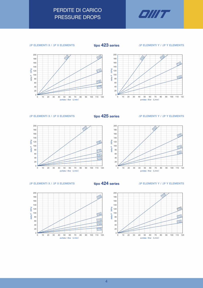
PERDITE DI CARICO PRESSURE DROPS
La perdita di carico totale si ottiene sommando
quella del corpo filtro con quella dell’elemento
filtrante ad un determinato valore di portata. Il valo-
re iniziale (cartuccia nuova) non dovrebbe superare
il 30% della taratura del by-pass.
The total pressure drop is calculated by adding the
values of the filter housings and filter elements at
the given flow rate. The initial value (new filter ele-
ment) should never exceed 30% of the by-pass
setting.
La perdita di carico del corpo filtro dipende solodalle dimensioni dell’attacco.
La valvola di by-pass protegge l’elemento filtrante
contro picchi di pressione, partenze a freddo o
quando la cartuccia è intasata.
The pressure drop related to the filter housingdepends only by the port size.
The by-pass valve avoids the filter element collapse
against pressure peaks, cold start conditions or
when the cartridge is clogged
ELEMENTO FILTRANTE – FILTER ELEMENT [30 CST]
La perdita di carico legata all’elemento dipende dal
diametro interno della cartuccia e dal media filtran-
te ed è legata direttamente alla viscosità.
The pressure drop of the element depends on the
ID of the cartridge and on the filter media with a
proportional relation with the oil-viscosity.
4
PERDITE DI CARICO PRESSURE DROPS
∆P ELEMENTI X / ∆P X ELEMENTS ∆P ELEMENTI Y / ∆P Y ELEMENTStipo 423 series
∆P ELEMENTI X / ∆P X ELEMENTS ∆P ELEMENTI Y / ∆P Y ELEMENTStipo 425 series
∆P ELEMENTI X / ∆P X ELEMENTS ∆P ELEMENTI Y / ∆P Y ELEMENTStipo 424 series

5
CODICE D’ORDINEORDERING CODIFICATION
HTM 425 F10 X N R 1
CHP 425 F10 X N
Taglia filtroNominal Size
423425424
-12
1/2” BSP3/4” BSPM22x1.5
-HTM-423HTM-424HTM-425
Media filtranteFiltration media
Codice kit guarnizioniSpare seal kit
NBR – Buna N FKM – Viton
KIT-HTM42-V
-
C10*
F03
F06
F10
F25
T25
10 µm
3 µm
6 µm
10 µm
25 µm
25 µm
Senza elementoNo elementsCartaCellulose Fibre inorganiche Inorganic fibre Fibre inorganiche Inorganic fibre Fibre inorganiche Inorganic fibre Fibre inorganiche Inorganic fibre 0Tela metallica (Aisi 304) Steel Aisi 304 Wire mesh
By-Pass
SR
X
Y*
Senza/No By-Pass6 bar/90 psi
GuarnizioniSeals
NV
NBR / Buna-NFKM / Viton
AttacchiConnection parts
Collasso elemento filtranteFilter element collapse
Basso Collasso 20 barLow Collapse 290 psiAlto Collasso 210 barHigh Collapse 3045 psi
Codice dell’elemento filtranteFilter Element Code
*Solo versione X - Only X version
Carta/Cellulose: βx (c) ≥ 2Fibra Inorganica/Inorganic Fiber: βx (c) ≥ 1000Tela Metallica/Wire Mesh: β Nominale/Nominal
** adatto per configurazione senza by-pass/recommended with no by-pass option
KIT-HTM42-N
6
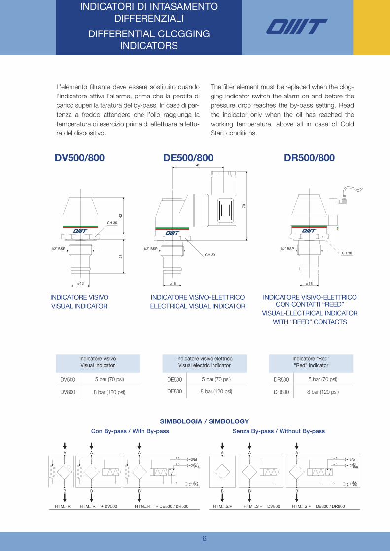
INDICATORI DI INTASAMENTO DIFFERENZIALI
DIFFERENTIAL CLOGGING INDICATORS
Indicatore visivoVisual indicator
DV800
DV500 5 bar (70 psi)
8 bar (120 psi)
Indicatore visivo elettricoVisual electric indicator
DE800
DE500
DR800
DR5005 bar (70 psi)
8 bar (120 psi)
Indicatore “Red”“Red” indicator
5 bar (70 psi)
8 bar (120 psi)
L’elemento filtrante deve essere sostituito quando
l’indicatore attiva l’allarme, prima che la perdita di
carico superi la taratura del by-pass. In caso di par-
tenza a freddo attendere che l’olio raggiunga la
temperatura di esercizio prima di effettuare la lettu-
ra del dispositivo.
The filter element must be replaced when the clog-
ging indicator switch the alarm on and before the
pressure drop reaches the by-pass setting. Read
the indicator only when the oil has reached the
working temperature, above all in case of Cold
Start conditions.
CH 30
70
ø16
45
CH 30
ø16
®
1/2” BSP
CH 30
4228
ø16
®
1/2” BSP
®
1/2” BSP
HTM...S/P HTM...S + DV800 HTM...S + DE800 / DR800
B B
A AN.A.
N.C.
C
B
A
3/bl2/
1/
N.A.
N.C.
C
HTM...R HTM...R + DV500 HTM...R + DE500 / DR500
B B
A A
B
A
brma
bkne
3/bl2/
1/
brma
bkne
C
INDICATORE VISIVOVISUAL INDICATOR
INDICATORE VISIVO-ELETTRICOELECTRICAL VISUAL INDICATOR
INDICATORE VISIVO-ELETTRICOCON CONTATTI “REED”
VISUAL-ELECTRICAL INDICATORWITH “REED” CONTACTS
SIMBOLOGIA / SIMBOLOGY
Con By-pass / With By-pass Senza By-pass / Without By-pass
DV500/800 DE500/800 DR500/800

7
FILTRI ALTA PRESSIONE SERIE HTM
HIGH PRESSURE IN LIGHT FILTER HTMSERIES
Tappo di chiusuraPlug
Indicatore visivoVisual indicator
Indicatore visivo elettrico “Reed”Visual el. “Reed” indicator
Indicatore visivo elettricoVisual el. indicator
TestinaFilter head
GuarnizioniSeals
Elemento ÞltranteFilter element
ContenitoreFilter Bowl
1) Assicurarsi che il filtro sia usato secondo i para-
metri di pressione, temperatura e compatibilità
illustrate in questo catalogo;
2) Sostituire l’elemento filtrante non appena l’indi-
catore attiva il segnale d’allarme alla tempera-
tura di esercizio. In caso nessun indicatore sia
montato seguire le indicazioni dell’impiantista;
3) Effettuare la manutenzione solo a sistema
spento, assicurandosi che non vi sia pressione
residua nel filtro;
4) Sostituire l’elemento filtrante esausto con una
cartuccia OMT, verificando il codice;
5) Sostituire le guarnizioni del filtro se necessario,
lubrificando i filetti e avvitando con cura.
1) Check the filter is working according to pres-
sure, temperature and oil compatibility, previ-
ously described in this catalogue;
2) Replace the filter element as soon as the clog-
ging indicator switches the alarm signal at work-
ing temperature. If no indicator is mounted, fol-
low the instruction of the system manufacturer;
3) Perform the maintenance only when the sys-
tem is switched off, ensuring that no residual
pressure is present;
4) Replace the clogged filter element with a OMT
cartridge, checking the part number;
5) If necessary, replace the filter gaskets, lubricat-
ing the threads and screwing with care.
CONSIGLI GENERALI - GENERAL TIPPS

8
NOTE

NOTE
OMT S.p.A. Via Lombardia, 14 - 24040 Calvenzano (Bg) ITALY - Tel. +39 0363 860311 - Fax +39 0363 335636www.omtfiltri.com - [email protected]
SCAMBIATORI
HEAT EXCHANGERS
FILTRI
FILTERS
ACCESSORI
ACCESSORIES
COMPONENTI
COMPONENTS
FLANGE/FLANGES
RACCORDI/COUPLINGS
BLOCCHI/MANIFOLDS
Filtri - Filters
15
ACCUMULATORI
ACCUMULATOR

SERIEMHP220 SERIES
MinifiltriMinifilters F
iltri-Filters
14

Versione - Version 01/022009
Con il fine di migliorare costantemente la qualità dei nostri prodotti, ci riserviamo il diritto di modificarne inqualsiasi momento le caratteristiche senza preavviso.È responsabilità della spettabile clientela la costante verifica dei dati contenuti nei cataloghi.Questo catalogo annulla e sostituisce i precedenti.
In order to constantly improve our products quality, we take the right to make changes to the catalogues at anytime without notice.Customers have the responsibility to continuously check all the information in the catalogues.This catalogue cancels and replaces the previous ones.

DESCRIZIONEDESCRIPTION
CARATTERISTICHE TECNICHE
TECHNICAL DATA
1
I filtri della serie MHP220 sono idonei per l’utilizzo su linee inpressione con portate fino a 6 L/min.
Posizionati in linea sulle tubazioni, sono disponibili con val-vola di by-pass e differenti gradi di filtrazione realizzati inmicrofibra inorganica, carta trattata e in rete metallica.
I filtri della serie MHP220 sono costruiti e provati secondo lenormative internazionali vigenti.
ISO 2941 Oleoidraulica - Elementi filtranti - Verifica dellaresistenza allo schiacciamento o allo scoppio;
ISO 2942 Oleoidraulica - Elementi filtranti - Verifica dellaconformità di fabbricazione e determinazione del punto diprima bolla;
ISO 2943 Oleoidraulica - Elementi filtranti - Verifica dellacompatibilità dei materiali con i fluidi;
ISO 3723 Oleoidraulica - Elementi filtranti - Verifica dellaresistenza alla deformazione assiale;
ISO 3724 Oleoidraulica - Elementi filtranti - Verifica dellecaratteristiche di un filtro mediante prova di resistenza a fati-ca in funzione della portata;
ISO 3968 Oleoidraulica - Filtri - Determinazione della perdi-ta di carico in funzione della portata;
ISO 16889 Oleoidraulica - Metodo Multi-pass per la valu-tazione delle caratteristiche di filtrazione di un elemento fil-trante.
MATERIALI DI COSTRUZIONE
Corpo filtroCorpo e contenitore Lega verdeTenute Buna-N o Viton (a richiesta)
Elementi filtrantiMateriali filtranti Fibre inorganiche
Carta trattataRete metallica acciaio
Reti di rinforzo Acciaio galvanizzato con rivestimen-to epossidico
Tubi di sostegno Acciaio zincatoFondelli Acciaio zincato
COMPATIBILITÀ DEI MATERIALI CON I LIQUIDI
I filtri della serie MHP220 sono compatibili con gli oli mine-rali tipo HH - HM - HR - HV - HG secondo ISO 6743/4 inun campo di taratura compreso tra -20°C e +95°C.Per applicazioni differenti quanto descritto in questo cata-logo, contattare l’ufficio commerciale della OMT S.p.A.
PRESSIONI DI LAVORO
Filtro completoPressione max. di esercizio 280 barValvola di by-pass inizio apertura 5 bar ±10%
Elementi filtrantiPressione differenziale di collasso 20 bar
CONSTRUCTION MATERIALS
Filter housingHead and bowl BrassGaskets Buna-N or Viton (optional)
Filter elementsFilter media Inorganic fibre
Resin treated paperSteel wire mesh
Support wire mesh Galvanized steel with epoxy treat-ment
Internal core Zinc treated steelEnd caps Zinc treated steel
FLUID COMPATIBILITY
MHP220 series is compatible with mineral oils type HH -HM - HR - HV - HG according to ISO 6743/4, for tempe-rature range between -20°C and +95°C.For any other application please contact the OMT S.p.A.Sales Department.
PRESSURE
Complete filterMax working pressure 280 barBy-pass valve set at 5 bar ±10%
Filter elementsFilter elements collapse rating 20 bar
The filters of our MHP220-series are suitable for use in pres-sure lines with flow rates up to 6 l/min.
They are to be placed in line on the pressure tube. Two ver-sions are available: with and without bypass valve, the repla-cement elements can be supplied either made of inorganicfibre, resin treated paper or made of wire mesh.
The filters of the MHP220 series are produced and testedaccording to current international standards.
ISO 2941 Hydraulic fluid power - Filter elements - Verificationof collapse/burst pressure resistance;
ISO 2942 Hydraulic fluid power - Filter elements - Verificationof fabrication integrity and determination of the first bubblepoint;
ISO 2943 Hydraulic fluid power - Filter elements - Verificationof material compatibility with fluid;
ISO 3723 Hydraulic fluid power - Filter elements - Methodfor end load tests;
ISO 3724 Hydraulic fluid power - Filter elements - Verificationof flow fatigue characteristics;
ISO 3968 Hydraulic fluid power - Filters - Evaluation of pres-sure drop versus flow characteristics;
ISO 16889 Hydraulic fluid power filters - Multipass methodfor evaluating filtration performance of a filter element.

2
Gradi di filtrazioneFiltration degrees
Codice /CodeGrado di filtrazione / Filtration degree
[µm] Rapporto di filtrazione / Beta ratio
G 10 β10≥200H 25 β25≥200
La particolare attenzione della nostra azienda nella scelta deimateriali filtranti ha permesso al reparto Ricerca e Sviluppodi creare elementi filtranti ad elevata efficienza di filtrazione ecapacità di ritenzione del contaminante solido (accumulo),capaci di soddisfare le applicazioni più esigenti.
The particular attention our company has always dedicatedto the choice of the filtration media used in our filters hasallowed our R&D department to develop filtration elementssuitable even for the most demanding applications, with ahigh filtration efficiency and an elevated dirt holding capaci-ty of solid contaminant.
ELEMENTI FILTRANTIIN FIBRA INORGANICA
Rapporto di filtrazione βx≥200, equivalente ad una efficien-za del 99,5% riferita alla dimensione indicata.
REPLACEMENT ELEMENTSMADE OF INORGANIC FIBRE
Filtration ratio βx≥200, equivalent to an efficiency of 99,5%concerning the indicated dimension.
Codice /CodeGrado di filtrazione / Filtration degree
[µm] Rapporto di filtrazione / Beta ratio
A 10 β10≥2B 25 β25≥2
ELEMENTI FILTRANTIIN CARTA TRATTATA
Rapporto di filtrazione βx≥2, equivalente ad una efficienzadel 50% riferita alla dimensione indicata.
REPLACEMENT ELEMENTSMADE OF RESIN TREATED PAPER
Filtration ratio βx≥2, equivalent to an efficiency of 50% con-cerning the indicated dimension.
Codice /CodeGrado di filtrazione / Filtration degree
[µm] Tipo di materiale / Wire material
L 10 Acciaio / Steel (Aisi 304)
M 20 Acciaio / Steel (Aisi 304)
C 60 Acciaio / Steel (Aisi 304)
U 90 Acciaio / Steel (Aisi 304)
E 125 Acciaio / Steel (Aisi 304)
ELEMENTI FILTRANTIIN RETE METALLICA
Rapporto di filtrazione βx≥2, equivalente ad una efficienzadel 50% riferita alla dimensione indicata.
REPLACEMENT ELEMENTSMADE OF WIRE MESH
Filtration ratio βx≥2, equivalent to an efficiency of 50% con-cerning the indicated dimension.
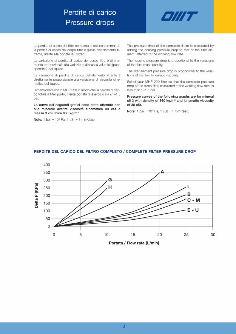
43
Perdite di caricoPressure drops
La perdita di carico del filtro completo si ottiene sommandola perdita di carico del corpo filtro e quella dell’elemento fil-trante, riferite alla portata di utilizzo.
La variazione di perdita di carico del corpo filtro è diretta-mente proporzionale alla variazione di massa volumica [pesospecifico] del liquido.
La variazione di perdita di carico dell’elemento filtrante èdirettamente proporzionale alla variazione di viscosità cine-matica del liquido.
Dimensionare il filtro MHP 220 in modo che la perdita di cari-co totale a filtro pulito, riferita portata di esercizio sia ≤1–1,5bar.
Le curve dei seguenti grafici sono state ottenute conolio minerale avente viscosità cinematica 30 cSt emassa 3 volumica 860 kg/m3.
Note: 1 bar = 105 Pa; 1 cSt = 1 mm2/sec.
The pressure drop of the complete filters is calculated byadding the housing pressure drop to that of the filter ele-ment, referred to the working flow rate.
The housing pressure drop is proportional to the variationsof the fluid mass density.
The filter element pressure drop is proportional to the varia-tions of the fluid kinematic viscosity.
Select your MHP 220 filter so that the complete pressuredrop of the clean filter, calculated at the working flow rate, isless than 1–1,5 bar.
Pressure curves of the following graphs are for mineraloil 3 with density of 860 kg/m3 and kinematic viscosityof 30 cSt.
Note: 1 bar = 105 Pa; 1 cSt = 1 mm2/sec.
PERDITE DEL CARICO DEL FILTRO COMPLETO / COMPLETE FILTER PRESSURE DROP
400
350
300
250
200
150
100
50
0
0 5 10 15 20 25 30
Portata / Flow rate [L/min]
DeltaP[KPa]
G
H
A
L
BC - M
E - U

4
Caratteristiche dimensionaliComplete filter with by-pass
FILTRO COMPLETO SENZA BY-PASSCOMPLETE FILTER WITHOUT BY-PASS
FILTRO COMPLETO CON BY-PASSCOMPLETE FILTER WITH BY-PASS
1/4
"B
SP
1/4
"B
SP
1/4
"B
SP
86
63
ø 50
1/4
"B
SP
86
63
ø 50
ELEMENTO FILTRANTE / FILTER ELEMENT
ø14
31
ø30
Coppia di serraggio contenitore: 50 NmBowl torque 50 Nm

5
Codice per l’ordinazioneHow to order
FILTRO COMPLETO / COMPLETE FILTER
OMT S.p.A. persegue una politica di continuo sviluppo dei propri prodotti, i dati contenuti in questo catalogo possonoessere modificati in qualsiasi momento senza preavviso da parte dell’azienda.
The informations printed in this bulletin is for reference only. It is subject to change without notice.
Ordinazione dell’elementodi ricambio
Replacement element
MHP 220 G N R
MHPR 220 G N
MHP
MHPR
SerieSeries
Filtro completoComplete filter
Elementi di ricambioReplacement element
Grandezza nominaleDimension
220
G
H
A
B
L
M
C
U
E
Materiali filtrantiFilter media
10 µm
25 µm
10 µm
25 µm
10 µm
25 µm
60 µm
90 µm
125 µm
βx≥200 Fibra inorganicaβx≥200 Inorganic fibre
βx≥200 Fibra inorganicaβx≥200 Inorganic fibre
βx≥2 Carta trattataβx≥2 Resin treated paper
βx≥2 Carta trattataβx≥2 Resin treated paper
Tela metallica (Aisi 304)Steel (Aisi 304) wire mesh
Tela metallica (Aisi 304)Steel (Aisi 304) wire mesh
Rete maglia quadra (Aisi 304)Square mesh (Aisi 304)
Rete maglia quadra (Aisi 304)Square mesh (Aisi 304)
Rete maglia quadra (Aisi 304)Square mesh (Aisi 304)
R
S
Valvola di by-passBy-pass valve
By-passDelta P 6 bar
Senza by-passNone
N
V
GuarnizioniSeals
Buna N
Viton
OMT s.p.a. Via Lombardia, 14 - 24040 Calvenzano (Bg) ITALY - Tel. +39 0363 860311 - Fax +39 0363 335636www.omtfiltri.com - [email protected]
SCAMBIATORIHEAT EXCHANGERS
FILTRIFILTERS
ACCESSORIACCESSORIES
COMPONENTICOMPONENTS
FLANGE / FLANGESRACCORDI/COUPLINGSBLOCCHI /MANIFOLDS
Filtri-Filters
14