om yonos para oem 4523676 01 1205 de en fr - GLo24 2017/juisim_6720819049-000-00.pdf · Die Pumpe...
29
Yonos PARA Pioneering for You de Einbau- und Betriebsanleitung en Installation and operating instructionst Istruzioni di montaggio, uso e manutenzione nl Inbouw- en bedieningsvoorschriften pl Instrukcja montażu i obsługi cs Návod k montáži a obsluze sk Návod na montáž a obsluhu 4 523 676-Ed.01 / 2012-05-Wilo
Transcript of om yonos para oem 4523676 01 1205 de en fr - GLo24 2017/juisim_6720819049-000-00.pdf · Die Pumpe...

Yonos PARA
Pioneering for You
de Einbau- und Betriebsanleitungen Installation and operating instructionst Istruzioni di montaggio, uso e manutenzionenl Inbouw- en bedieningsvoorschriften
pl Instrukcjamontażuiobsługics Návodk montážiaobsluzesk Návodnamontážaobsluhu
4 523 676-Ed.01 / 2012-05-Wilo

Fig. 1:
A B
Fig. 2:
RKA RKC
Fig. 3a: Fig. 3b:
H max
H
H min
Hs
Q
Hs1/2
H max
H
H min
Hs
Q

Fig. 3c: Fig. 3d:
Fig. 3e: Fig. 4:
Fig. 5:
a b
max
H
min
II
III
I
Q
max
n/¹/min
min
0 5 85 88 93 100 PWM %
max
min
0 7 12 15 95 100 PWM %
n/¹/min
PE N L

Fig. 5:
c d
e f
Fig. 6:

de Einbau- und Betriebsanleitung 3
en Installation and operating instructions 13


Einbau- und Betriebsanleitung Wilo-Yonos PARA 3
Deutsch
Einbau- und Betriebsanleitung1 Allgemeines
Über dieses DokumentDie Sprache der Originalbetriebsanleitung ist Englisch. Alle weiteren Sprachen dieser Anleitung sind eine Übersetzung der Originalbetriebsanleitung.Die Einbau- und Betriebsanleitung ist Bestandteil des Produktes. Sie ist jeder-zeit in Produktnähe bereitzustellen. Das genaue Beachten dieser Anweisung ist Voraussetzung für den bestimmungsgemäßen Gebrauch und die richtige Bedie-nung des Produktes.Die Einbau- und Betriebsanleitung entspricht der Ausführung des Produktes und dem Stand der zugrunde gelegten sicherheitstechnischen Normen bei Drucklegung.EG-Konformitätserklärung:Eine Kopie der EG-Konformitätserklärung ist Bestandteil dieser Betriebsanlei-tung.Bei einer mit uns nicht abgestimmten technischen Änderung der dort genann-ten Bauarten verliert diese Erklärung ihre Gültigkeit.
2 SicherheitDiese Betriebsanleitung enthält grundlegende Hinweise, die bei Montage, Betrieb und Wartung zu beachten sind. Daher ist diese Betriebsanleitung unbe-dingt vor Montage und Inbetriebnahme vom Monteur sowie dem zuständigen Fachpersonal/Betreiber zu lesen.Es sind nicht nur die unter diesem Hauptpunkt Sicherheit aufgeführten allge-meinen Sicherheitshinweise zu beachten, sondern auch die unter den folgenden Hauptpunkten mit Gefahrensymbolen eingefügten, speziellen Sicherheitshin-weise.
2.1 Kennzeichnung von Hinweisen in der Betriebsanleitung
Symbole:
Allgemeines Gefahrensymbol
Gefahr durch elektrische Spannung
HINWEIS:
Signalwörter:
GEFAHR!Akut gefährliche Situation.Nichtbeachtung führt zu Tod oder schwersten Verletzungen.
WARNUNG!Der Benutzer kann (schwere) Verletzungen erleiden. 'Warnung' beinhaltet, dass (schwere) Personenschäden wahrscheinlich sind, wenn der Hinweis missachtet wird.
VORSICHT!Es besteht die Gefahr, das Produkt/die Anlage zu beschädigen. 'Vorsicht' bezieht sich auf mögliche Produktschäden durch Missachten des Hinweises.

Deutsch
4 WILO SE 05/2012
HINWEIS: Ein nützlicher Hinweis zur Handhabung des Produktes. Er macht auch auf mög-liche Schwierigkeiten aufmerksam.
Direkt am Produkt angebrachte Hinweise wie z.B.• Drehrichtungspfeil,• Kennzeichen für Anschlüsse,• Typenschild,• Warnaufkleber,
müssen unbedingt beachtet und in vollständig lesbarem Zustand gehalten wer-den.
2.2 PersonalqualifikationDas Personal für die Montage, Bedienung und Wartung muss die entsprechende Qualifikation für diese Arbeiten aufweisen. Verantwortungsbereich, Zuständig-keit und Überwachung des Personals sind durch den Betreiber sicherzustellen. Liegen dem Personal nicht die notwendigen Kenntnisse vor, so ist dieses zu schulen und zu unterweisen. Falls erforderlich kann dies im Auftrag des Betrei-bers durch den Hersteller des Produktes erfolgen.
2.3 Gefahren bei Nichtbeachtung der SicherheitshinweiseDie Nichtbeachtung der Sicherheitshinweise kann eine Gefährdung für Perso-nen, die Umwelt und Produkt/Anlage zur Folge haben. Die Nichtbeachtung der Sicherheitshinweise führt zum Verlust jeglicher Schadensersatzansprüche.Im Einzelnen kann Nichtbeachtung beispielsweise folgende Gefährdungen nach sich ziehen:
• Gefährdungen von Personen durch elektrische, mechanische und bakteriologi-sche Einwirkungen,
• Gefährdung der Umwelt durch Leckage von gefährlichen Stoffen,• Sachschäden,• Versagen wichtiger Funktionen des Produktes/der Anlage,• Versagen vorgeschriebener Wartungs- und Reparaturverfahren.
2.4 Sicherheitsbewusstes ArbeitenDie in dieser Betriebsanleitung aufgeführten Sicherheitshinweise, die bestehen-den nationalen Vorschriften zur Unfallverhütung sowie eventuelle interne Arbeits-, Betriebs- und Sicherheitsvorschriften des Betreibers sind zu beachten.
2.5 Sicherheitshinweise für den BetreiberDieses Gerät ist nicht dafür bestimmt, durch Personen (einschließlich Kinder) mit eingeschränkten physischen, sensorischen oder geistigen Fähigkeiten oder mangels Erfahrung und/oder mangels Wissen benutzt zu werden, es sei denn, sie werden durch eine für ihre Sicherheit zuständige Person beaufsichtigt oder erhielten von ihr Anweisungen, wie das Gerät zu benutzen ist. Kinder müssen beaufsichtigt werden, um sicherzustellen, dass sie nicht mit dem Gerät spielen.

Einbau- und Betriebsanleitung Wilo-Yonos PARA 5
Deutsch
• Führen heiße oder kalte Komponenten am Produkt/der Anlage zu Gefahren, müssen diese bauseitig gegen Berührung gesichert sein.
• Berührungsschutz für sich bewegende Komponenten (z.B. Kupplung) darf bei sich im Betrieb befindlichem Produkt nicht entfernt werden.
• Leckagen (z.B. Wellendichtung) gefährlicher Fördermedien (z.B. explosiv, giftig, heiß) müssen so abgeführt werden, dass keine Gefährdung für Personen und die Umwelt entsteht. Nationale gesetzliche Bestimmungen sind einzuhalten.
• Gefährdungen durch elektrische Energie sind auszuschließen. Weisungen loka-ler oder genereller Vorschriften [z.B. IEC, VDE usw.] und der örtlichen Energie-versorgungsunternehmen sind zu beachten.
• Störung elektronischer Geräte durch elektromagnetische Felder. Elektromag-netische Felder werden beim Betrieb von Pumpen mit Umrichter erzeugt. Dadurch können elektronische Geräte gestört werden. Die Folge kann eine Fehlfunktion des Gerätes sein, die zu gesundheitlichen Personenschäden bis hin zum Tod, z.B. bei Trägern implantierter aktiver oder passiver medizinischer Geräte, führen kann. Daher sollte während des Betriebs der Aufenthalt von Personen z.B. mit Herz-schrittmachern in der Nähe der Anlage/Pumpe untersagt werden. Bei magneti-schen oder elektronischen Datenträger kann es zu Datenverlusten kommen.
WARNUNG! Gefahr durch starkes Magnetfeld!Im Inneren der Maschine besteht immer ein starkes Magnetfeld welches bei unsachgemäßer Demontage zu Personen- und Sachschäden führen kann.
• Die Entnahme des Rotors aus dem Motorgehäuse ist grundsätzlich nur durch autorisiertes Fachpersonal zulässig!
• Es besteht Quetschgefahr! Beim Herausziehen des Rotors aus dem Motor kann dieser durch das starke Magnetfeld schlagartig in seine Ausgangslage zurück-gezogen werden.
• Wird die aus Laufrad, Lagerschild und Rotor bestehende Einheit aus dem Motor herausgezogen, sind besonders Personen, die medizinische Hilfsmittel wie Herzschrittmacher, Insulinpumpen, Hörgeräte, Implantate oder ähnli-ches verwenden, gefährdet. Tod, schwere Körperverletzung und Sachschä-den können die Folge sein. Für diese Personen ist in jedem Fall eine arbeitsmedizinische Beurteilung erforderlich.
• Elektronische Geräte können durch das starke Magnetfeld des Rotors in ihrer Funktion beeinträchtigt oder beschädigt werden.
• Befindet sich der Rotor außerhalb des Motors, können magnetische Gegen-stände schlagartig angezogen werden. Dies kann Körperverletzungen und Sachschäden zur Folge haben.
Im zusammengebauten Zustand wird das Magnetfeld des Rotors im Eisenkreis des Motors geführt. Dadurch ist außerhalb der Maschine kein gesundheits-schädliches Magnetfeld nachweisbar.

Deutsch
6 WILO SE 05/2012
2.6 Sicherheitshinweise für Montage- und WartungsarbeitenDer Betreiber hat dafür zu sorgen, dass alle Montage- und Wartungsarbeiten von autorisiertem und qualifiziertem Fachpersonal ausgeführt werden, das sich durch eingehendes Studium der Betriebsanleitung ausreichend informiert hat.Die Arbeiten an dem Produkt/der Anlage dürfen nur im Stillstand durchgeführt werden. Die in der Einbau- und Betriebsanleitung beschriebene Vorgehens-weise zum Stillsetzen des Produktes/der Anlage muss unbedingt eingehalten werden.Unmittelbar nach Abschluss der Arbeiten müssen alle Sicherheits- und Schutz-einrichtungen wieder angebracht bzw. in Funktion gesetzt werden.
2.7 Eigenmächtiger Umbau und ErsatzteilherstellungEigenmächtiger Umbau und Ersatzteilherstellung gefährden die Sicherheit des Produktes/Personals und setzen die vom Hersteller abgegebenen Erklärungen zur Sicherheit außer Kraft. Veränderungen des Produktes sind nur nach Absprache mit dem Hersteller zulässig. Originalersatzteile und vom Hersteller autorisiertes Zubehör dienen der Sicherheit. Die Verwendung anderer Teile hebt die Haftung für die daraus entstehenden Folgen auf.
2.8 Unzulässige BetriebsweisenDie Betriebssicherheit des gelieferten Produktes ist nur bei bestimmungsgemä-ßer Verwendung entsprechend Abschnitt 4 der Betriebsanleitung gewährleis-tet. Die im Katalog/Datenblatt angegebenen Grenzwerte dürfen auf keinen Fall unter- bzw. überschritten werden.
3 Transport und ZwischenlagerungSofort nach Erhalt das Produktes auf Transportschäden überprüfen.
VORSICHT! Gefahr von Sachschäden!Unsachgemäßer Transport und unsachgemäße Zwischenlagerung können zu Sachschäden am Produkt führen.Die Pumpe ist gegen Feuchtigkeit, Frost und mechanische Beschädigung während des Transports und der Zwischenlagerung zu schützen.
TransportbedingungenDas Produkt darf keinen Temperaturen außerhalb des Bereichs von -40 °C bis +85°C ausgesetzt werden. Die Transportbedingungen sind für maximal 3 Monate zulässig.
LagerbedingungenDas Produkt darf keinen Temperaturen außerhalb des Bereichs von 0 °C bis +40°C ausgesetzt werden. Die Lagerzeit kann bis zu 2 Jahre betragen. Restli-ches Wasser, im Falle von Produktionsprüfungen des Kunden, kann nicht zu Frostschäden führen.
Einbau- und Betriebsanleitung Wilo-Yonos PARA 7
Deutsch
4 Bestimmungsgemäße VerwendungDie Umwälzpumpen der Baureihe Wilo-Yonos PARA sind für Warmwasser-Hei-zungsanlagen und ähnliche Systeme mit ständig wechselnden Förderströmen konzipiert. Zugelassene Fördermedien sind Heizungswasser nach VDI 2035, Wasser-/Glykolgemische im Mischungsverhältnis 1:1. Bei Beimischungen von Glykol sind die Förderdaten der Pumpe entsprechend der höheren Viskosität, abhängig vom prozentualen Mischungsverhältnis zu korrigieren. Zur bestimmungsgemäßen Verwendung gehört auch die Einhaltung dieser Anleitung.Jede darüber hinausgehende Verwendung gilt als nicht bestimmungsgemäße Verwendung.
5 Angaben über das Erzeugnis
5.1 Typenschlüssel
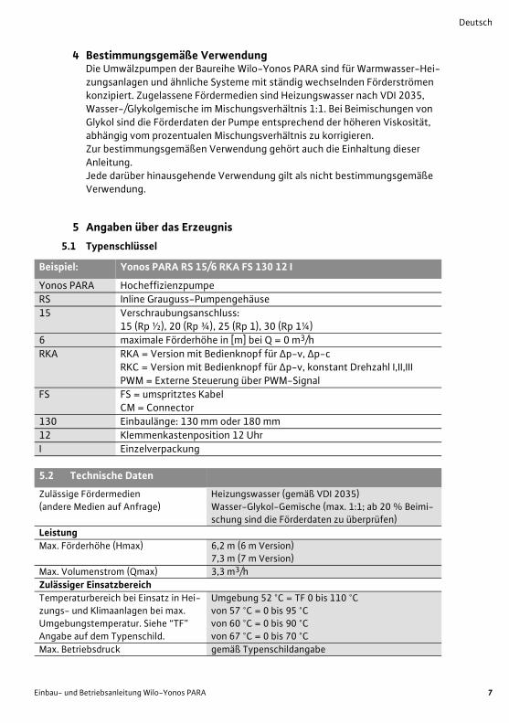
Beispiel: Yonos PARA RS 15/6 RKA FS 130 12 I
Yonos PARA Hocheffizienzpumpe
RS Inline Grauguss-Pumpengehäuse
15 Verschraubungsanschluss: 15 (Rp ½), 20 (Rp ¾), 25 (Rp 1), 30 (Rp 1¼)
6 maximale Förderhöhe in [m] bei Q = 0 m3/h
RKA RKA = Version mit Bedienknopf für Δp-v, Δp-cRKC = Version mit Bedienknopf für Δp-v, konstant Drehzahl I,II,IIIPWM = Externe Steuerung über PWM-Signal
FS FS = umspritztes KabelCM = Connector
130 Einbaulänge: 130 mm oder 180 mm
12 Klemmenkastenposition 12 Uhr
I Einzelverpackung
5.2 Technische Daten
Zulässige Fördermedien (andere Medien auf Anfrage)
Heizungswasser (gemäß VDI 2035)Wasser-Glykol-Gemische (max. 1:1; ab 20 % Beimi-schung sind die Förderdaten zu überprüfen)
Leistung
Max. Förderhöhe (Hmax) 6,2 m (6 m Version)7,3 m (7 m Version)
Max. Volumenstrom (Qmax) 3,3 m3/h
Zulässiger Einsatzbereich
Temperaturbereich bei Einsatz in Hei-zungs- und Klimaanlagen bei max. Umgebungstemperatur. Siehe “TF” Angabe auf dem Typenschild.
Umgebung 52 °C = TF 0 bis 110 °Cvon 57 °C = 0 bis 95 °Cvon 60 °C = 0 bis 90 °Cvon 67 °C = 0 bis 70 °C
Max. Betriebsdruck gemäß Typenschildangabe

Deutsch
8 WILO SE 05/2012
6 Beschreibung und Funktion
6.1 Beschreibung der PumpeDie Pumpe (Fig. 1A RKA/RKC Version, Fig. 1B PWM Version) besteht aus einer Hydraulik, einem Nassläufermotor mit Permanentmagnetrotor und einem elek-tronischen Regelmodul mit integriertem Frequenzumrichter. Das Regelmodul enthält entweder einen Bedienknopf (selbstregelde Pumpe RKA/RKC Version) oder eine Drehzahlregelung über ein externes PWM Signal (PWM Version). Beide Versionen sind mit einer LED-Anzeige ausgestattet um den Betriebszustand der Pumpe anzuzeigen (siehe Kapitel 10).
6.2 FunktionenAlle Funktionen lassen sich mit dem Bedienknopf oder über ein externes PWM-Signal einstellen, aktivieren oder deaktivieren.
Einstellungen über den Bedienknopf
Differenzdruck variabel (Δp-v):
Der Differenzdruck-Sollwert H wird über dem zulässigen Förderstrombereich linear zwischen ½H und H erhöht (Fig. 3a). Der von der Pumpe erzeugte Differenzdruck wird auf dem jeweiligen Differenz-druck-Sollwert geregelt. Diese Regelungsart bietet sich besonders bei Hei-zungsanlagen mit Heizkörpern an, da die Fließgeräusche an den Thermostatventilen reduziert werden.
Differenzdruck konstant (Δp-c):Der Differenzdruck-Sollwert H wird über dem zulässigen Förderstrombereich konstant auf dem eingestellten Differenzdruck-Sollwert bis zur Maximalkenn-linie gehalten (Fig. 3b). Wilo empfiehlt diese Regelungsart bei Fußbodenheiz-kreisen oder älteren Heizungssystemen mit groß dimensionierten Rohrleitungen, sowie bei allen Anwendungen die keine veränderliche Rohrnetz-kennlinie haben, wie z. B. Boilerladepumpen
Elektroanschluss
Netzanschluss 1~230 V +10%/-15%, 50/60 Hz (gem. IEC 60038)
Motor/Elektronik
Elektromagnetische Verträglichkeit EN 61800-3
Störaussendung EN 61000-6-3 / EN 61000-6-4
Störfestigkeit EN 61000-6-1 / EN 61000-6-2
Schutzart IP X4D
Isolationsklasse F
RoHS konform
Mindest Zulaufhöhe am Sauganschluss zur Vermeidung von Kavition bei Wasser-Fördertemperatur
Mindestzulaufhöhe bei 50/95/110°C 0,5 / 4,5 / 11 m
5.2 Technische Daten

Einbau- und Betriebsanleitung Wilo-Yonos PARA 9
Deutsch
Entlüftungsfunktion (RKA Version):
Bei der automatischen Entlüftungsfunktion (10 min.) läuft die Pumpe abwech-selnd mit hohen und niedrigen Drehzahlen und führt Luftansammlungen aus der Pumpe direkt dem Entlüftungsventil des Systems zu.
Konstant-Drehzahl I, II, III (RKC Version)Die Pumpe läuft konstant bei voreingestellter Festdrehzahl (Fig. 3c)
Externe Regelung über ein PWM Signal (PWM Version)Der erforderliche Soll-/Istwertvergleich wird für eine Regelung von einem externen Regler übernommen. Als Stellgröße wird der Pumpe von dem externen Regler ein PWM Signal zugeführt.Der PWM-Signal Erzeuger gibt an die Pumpe eine periodische Folge von Impul-sen (der Tastgrad) gemäß DIN IEC 60469-1. Die Stellgröße wird durch das Ver-hältnis der Impulsdauer zur Impulsperiodendauer bestimmt. Der Tastgrad wird als dimensionslose Verhältniszahl mit einem Wert von 0 … 1 % oder 0 … 100 % angegeben. PWM Signallogik 1 (Heizung) Fig. 3dund PWM Signallogik 2 (Solar) Fig. 3e .
7 Installation und elektrischer Anschluss
GEFAHR! Lebensgefahr!Unsachgemäße Installation und unsachgemäßer elektrischer Anschluss kön-nen lebensgefährlich sein.
• Installation und elektrischen Anschluss nur durch Fachpersonal und gemäß geltenden Vorschriften durchführen lassen!
• Vorschriften zur Unfallverhütung beachten!
7.1 Installation• Einbau der Pumpe erst nach Abschluss aller Schweiß- und Lötarbeiten und der
ggf. erforderlichen Spülung des Rohrsystems.• Die Pumpe an gut zugänglicher Stelle montieren zur leichten Überprüfung bzw.
Demontage.• Bei Einbau im Vorlauf offener Anlagen muss der Sicherheitsvorlauf vor der
Pumpe abzweigen (DIN EN 12828).• Vor und hinter der Pumpe sollten Absperrarmaturen eingebaut werden, um
einen evtl. Pumpenaustausch zu erleichtern. • Montage so durchzuführen, dass evtl. Leckagewasser nicht auf das
Regelmodul tropfen kann, • Hierzu oberen Absperrschieber seitlich ausrichten.
• Bei Wärmedämmarbeiten darauf achten, dass der Pumpenmotor, sowie das Modul nicht gedämmt werden. Die Kondensatablauföffnungen müssen frei sein.
• Spannungsfreie Montage mit waagerecht liegendem Pumpenmotor durchfüh-ren. Einbaulagen für die Pumpe siehe Fig. 4.
• Richtungspfeile auf dem Pumpengehäuse zeigen die Fließrichtung an.

Deutsch
10 WILO SE 05/2012
7.2 Elektrischer Anschluss
GEFAHR! Lebensgefahr!Bei unsachgemäßem elektrischen Anschluss besteht Lebensgefahr durch Stromschlag.
• Elektrischen Anschluss nur durch vom örtlichen Energieversorger zugelasse-nen Elektroinstallateur und entsprechend den örtlich geltenden Vorschriften ausführen lassen.
• Vor dem Arbeiten die Versorgungsspannung trennen.
• Stromart und Spannung des Netzanschlusses müssen den Angaben auf dem Typenschild entsprechen.
• max. Vorsicherung: 10 A, träge.• Pumpe vorschriftsmäßig erden.• Netzanschluss: L, N, PE• Anschluss des Netzkabels vornehmen:
1. Standard: 3-adriges umspritztes Kabel mit Messing Aderendhülsen 2. Optional: Molex 3-Wge Stecker Fig.63. Optional: Wilo-Connector (Fig. 5a bis 5e).
Demontage des Wilo-Connectors nach Fig. 5f vornehmen, dazu ist ein Schraubendreher erforderlich.
• Anschluss des Signalkabels (PWM) vornehmen:• Braun, PWM + (Signaleigenschaften)• Blau, PWM – (Masse)
8 Inbetriebnahme
WARNUNG! Gefahr von Personen- und Sachschäden!Unsachgemäße Inbetriebnahme kann zu Personen- und Sachschäden führen.
• Inbetriebnahme nur durch qualifiziertes Fachpersonal! • Je nach Betriebszustand der Pumpe bzw. der Anlage (Temperatur des För-
dermediums) kann die gesamte Pumpe sehr heiß werden. Es besteht Verbrennungsgefahr bei Berührung der Pumpe!
8.1 Bedienung (nur Version mit Bedienknopf)Die Bedienung der Pumpe erfolgt über den Bedienknopf. Durch drehen des Knopfes können die unterschiedlichen Reglungsarten ausgewählt und die Ein-stellung der Förderhöhe oder konstanten Drehzahl (Fig. 2 RKA / RKC) vorge-nommen werden.Werkseinstellung der Pumpe: RKA Version: Δp-c max.
RKC Version: max. Drehzahl III
8.1.1 Füllen und EntlüftenAnlage sachgerecht füllen und entlüften. Falls eine direkte Entlüftung des Rotorraumes erforderlich sein sollte, kann die Entlüftungsfunktion (Version RKA) manuell gestartet werden.

Einbau- und Betriebsanleitung Wilo-Yonos PARA 11
Deutsch
Durch Drehen des Bedienknopfes in die Mittelstellung, auf das Symbol für die Entlüftung, wird nach 3 Sekunden die Entlüftungsfunktion aktiviert.Die Dauer der Entlüftungsfunktion beträgt 10 Minuten und wird durch schnelles grünes Blinken der LED angezeigt. Während der Entlüftungsfunktion kann es zu Geräuschbildung kommen. Der Vorgang kann auf Wunsch durch Drehen des Knopfes abgebrochen werden.Nach Ablauf der 10 Minuten stoppt die Pumpe und geht automatisch in die Regelungsart Δp-c max. Danach muss die Regelungsart und die Förderhöhe eingestellt werden, falls die Pumpe nicht bei Δp-c max weiter betrieben werden soll.
HINWEIS: Die Entlüftungsfunktion entfernt angesammelte Luft aus dem Rotor-raum der Pumpe. Das Heizungssystem wird durch die Entlüftungsfunktion nicht entlüftet.
8.1.2 Einstellung der RegelungsartDurch Drehen des Bedienknopfes wird das Symbol der Regelungsart gewählt und die gewünschte Förderhöhe / Konstant-Drehzahl eingestellt.
Differenzdruck variabel (Δp-v): Fig. 2 RKA / RKC, Fig. 3aLinks der Mittelstellung wird die Pumpe für den Regelmodus ∆p-v eingestellt.
Differenzdruck konstant (Δp-c): Fig. 2 RKA Fig. 3bRechts der Mittelstellung wird die Pumpe für den Regelmodus ∆p-c eingestellt.
Konstant-Drehzahl I, II, III: Fig. 2 RKC, Fig. 3cRechts der Mittelstellung wird die Pumpe für den Regelmodus Konstant-Dreh-zahl eingestellt. Bei dieser Regelungsart arbeitet die Pumpe nicht selbstregelnd, sie läuft konstant bei voreingestellter Festdrehzahl.
HINWEIS: Bei einer Netzunterbrechung bleiben alle Einstellungen und Anzeigen erhalten.
9 Wartung
GEFAHR! Lebensgefahr!Bei Arbeiten an elektrischen Geräten besteht Lebensgefahr durch Strom-schlag.
• Bei allen Wartungs- und Reparaturarbeiten die Pumpe spannungsfrei schal-ten und gegen unbefugtes Wiedereinschalten sichern.
• Schäden am Anschlusskabel sind grundsätzlich nur durch einen qualifizierten Elektroinstallateur zu beheben.
Nach erfolgten Wartungs- und Reparaturarbeiten die Pumpe entsprechend Kapitel „Installation und elektrischer Anschluss“ einbauen bzw. anschließen. Das Einschalten der Pumpe erfolgt nach Kapitel „Inbetriebnahme“.
Deutsch
12 WILO SE 05/2012
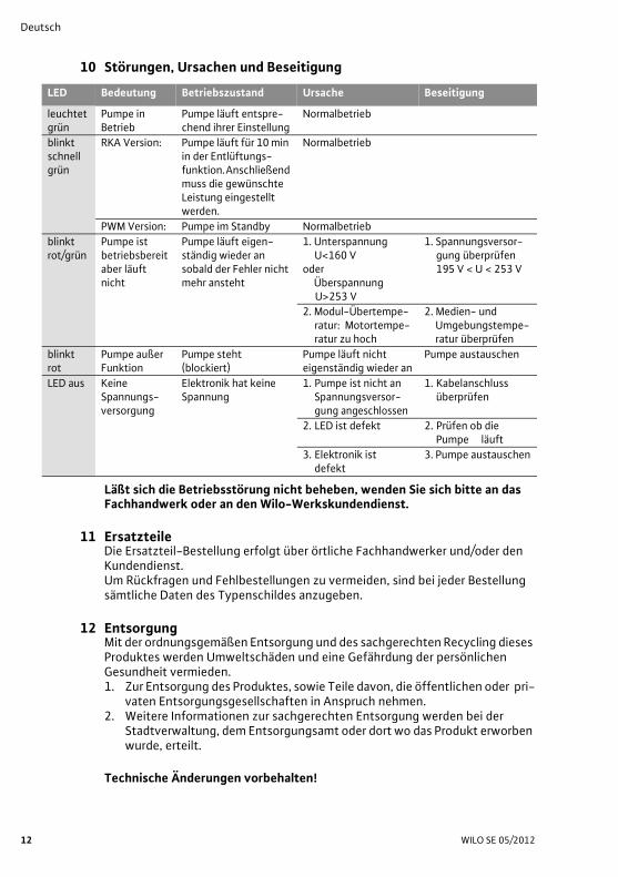
10 Störungen, Ursachen und Beseitigung
Läßt sich die Betriebsstörung nicht beheben, wenden Sie sich bitte an das Fachhandwerk oder an den Wilo-Werkskundendienst.
11 ErsatzteileDie Ersatzteil-Bestellung erfolgt über örtliche Fachhandwerker und/oder den Kundendienst.Um Rückfragen und Fehlbestellungen zu vermeiden, sind bei jeder Bestellung sämtliche Daten des Typenschildes anzugeben.
12 EntsorgungMit der ordnungsgemäßen Entsorgung und des sachgerechten Recycling dieses Produktes werden Umweltschäden und eine Gefährdung der persönlichen Gesundheit vermieden.1. Zur Entsorgung des Produktes, sowie Teile davon, die öffentlichen oder pri-
vaten Entsorgungsgesellschaften in Anspruch nehmen.2. Weitere Informationen zur sachgerechten Entsorgung werden bei der
Stadtverwaltung, dem Entsorgungsamt oder dort wo das Produkt erworben wurde, erteilt.
Technische Änderungen vorbehalten!
LED Bedeutung Betriebszustand Ursache Beseitigung
leuchtet grün
Pumpe in Betrieb
Pumpe läuft entspre-chend ihrer Einstellung
Normalbetrieb
blinkt schnell grün
RKA Version: Pumpe läuft für 10 min in der Entlüftungs-funktion. Anschließend muss die gewünschte Leistung eingestellt werden.
Normalbetrieb
PWM Version: Pumpe im Standby Normalbetrieb
blinkt rot/grün
Pumpe ist betriebsbereit aber läuft nicht
Pumpe läuft eigen-ständig wieder an sobald der Fehler nicht mehr ansteht
1. Unterspannung U<160 V
oderÜberspannung
U>253 V
1. Spannungsversor-gung überprüfen195 V < U < 253 V
2. Modul-Übertempe-ratur: Motortempe-ratur zu hoch
2. Medien- und Umgebungstempe-ratur überprüfen
blinkt rot
Pumpe außer Funktion
Pumpe steht(blockiert)
Pumpe läuft nicht eigenständig wieder an
Pumpe austauschen
LED aus Keine Spannungs-versorgung
Elektronik hat keine Spannung
1. Pumpe ist nicht an Spannungsversor-gung angeschlossen
1. Kabelanschluss überprüfen
2. LED ist defekt 2. Prüfen ob die Pumpe läuft
3. Elektronik ist defekt
3. Pumpe austauschen
Installation and Operating Instructions Wilo-Yonos PARA 13
English
Installation and Operating Instructions1 General
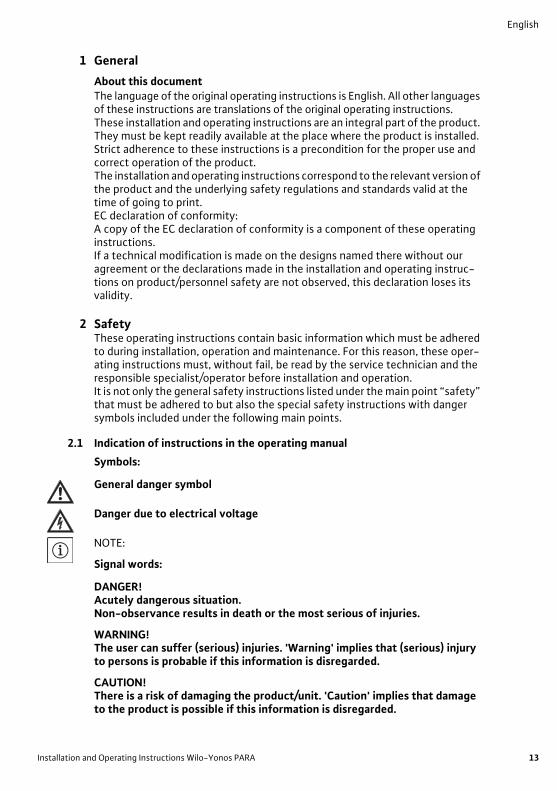
About this documentThe language of the original operating instructions is English. All other languages of these instructions are translations of the original operating instructions.These installation and operating instructions are an integral part of the product. They must be kept readily available at the place where the product is installed. Strict adherence to these instructions is a precondition for the proper use and correct operation of the product.The installation and operating instructions correspond to the relevant version of the product and the underlying safety regulations and standards valid at the time of going to print.EC declaration of conformity:A copy of the EC declaration of conformity is a component of these operating instructions.If a technical modification is made on the designs named there without our agreement or the declarations made in the installation and operating instruc-tions on product/personnel safety are not observed, this declaration loses its validity.
2 SafetyThese operating instructions contain basic information which must be adhered to during installation, operation and maintenance. For this reason, these oper-ating instructions must, without fail, be read by the service technician and the responsible specialist/operator before installation and operation.It is not only the general safety instructions listed under the main point “safety” that must be adhered to but also the special safety instructions with danger symbols included under the following main points.
2.1 Indication of instructions in the operating manual
Symbols:
General danger symbol
Danger due to electrical voltage
NOTE:
Signal words:
DANGER!Acutely dangerous situation.Non-observance results in death or the most serious of injuries.
WARNING!The user can suffer (serious) injuries. 'Warning' implies that (serious) injury to persons is probable if this information is disregarded.
CAUTION!There is a risk of damaging the product/unit. 'Caution' implies that damage to the product is possible if this information is disregarded.

English
14 WILO SE 05/2012
NOTE: Useful information on handling the product. It draws attention to possible pro-blems.
Information applied directly to the product, such as:• Direction of rotation arrow,
• Identifiers for connections,
• Name plate,
• warning sticker,
must be strictly compliant with and kept in a fully legible condition.
2.2 Personnel qualificationsThe installation, operating and maintenance personnel must have the appropri-ate qualifications for this work. Area of responsibility, terms of reference and monitoring of the personnel have to be ensured by the operator. If the person-nel are not in possession of the necessary knowledge, they have to be trained and instructed. This can be accomplished if necessary by the manufacturer of the product at the request of the operator.
2.3 Danger in the event of non-observance of the safety instructionsNon-observance of the safety instructions can result in risk of injury to persons and damage to the environment and the product/unit. Non-observance of the safety instructions results in the loss of any claims to damages. In detail, non-observance can, for example, result in the following risks:
• Danger to persons from electrical, mechanical and bacteriological influences,
• Damage to the environment due to leakage of hazardous materials,
• Property damage,
• Failure of important product/unit functions,
• Failure of required maintenance and repair procedures.
2.4 Safety consciousness on the jobThe safety instructions included in this installation and operating instructions, the existing national regulations for accident prevention together with any internal working, operating and safety regulations of the operator are to be com-pliant with.
2.5 Safety instructions for the operatorThis appliance is not intended for use by persons (including children) with reduced physical, sensory or mental capabilities, or lack of experience and knowledge, unless they have been given supervision or instruction concerning use of the appliance by a person responsible for their safety. Children should be supervised to ensure that they do not play with the appli-ance.
• If hot or cold components on the product/the unit lead to hazards, local meas-ures must be taken to guard them against touching.

Installation and Operating Instructions Wilo-Yonos PARA 15
English
• Guards protecting against touching moving components (such as the coupling) must not be removed whilst the product is in operation.
• Leakages (e.g. from a shaft seal) of hazardous fluids (e.g. explosive, toxic or hot) must be led away so that no danger to persons or to the environment arises. National statutory provisions are to be complied with.
• Danger from electrical current must be eliminated. Local directives or general directives [e.g. IEC, VDE etc.] and local energy supply companies must be adhered to.
• Faults of electronic devices due to electromagnetic fields Electromagnetic fields are created during the operation of pumps with frequency converter. Interference of electronic devices may be the result. The result may be a device malfunction, which can result in damage to the health or even death, e.g. of per-sons carrying implanted active or passive medical devices.Therefore, during operation the presence of any persons e.g. with cardiac pace-makers in the vicinity of the unit/pump should be prohibited. With magnetic or electronic data media, the loss of data is possible.
WARNING! Danger due to strong magnetic field!Inside the machine there is always a strong magnetic field that can cause injury and damage to property in the event of incorrect dismantling.
• It is only permitted to have the rotor removed from the motor housing by qualified personnel!
• There is a crushing hazard! When pulling the rotor out of the motor, it may be suddenly pulled back into its initial position by the strong magnetic field.
• If the unit consisting of impeller, bearing shield and rotor is pulled out of the motor, persons with medical aids, such as cardiac pacemakers, insulin pumps, hearing aids, implants or similar are at risk. Death, severe injury and damage to property may be the result. For such persons, a professional medical assessment is always necessary.
• Electronic devices may be impaired functionally or damaged by the strong magnetic field of the rotor.
• If the rotor is outside the motor, magnetic objects may be attracted very suddenly. That can result in injury and damage to property.
In assembled condition, the rotor's magnetic field is guided in the motor's iron core. There is therefore no harmful magnetic field outside the machine.
2.6 Safety instructions for installation and maintenance workThe operator must ensure that all installation and maintenance work is carried out by authorized and qualified personnel, who are sufficiently informed from their own detailed study of the operating instructions.Work to the product/unit must only be carried out when at a standstill. It is man-datory that the procedure described in the installation and operating instruc-tions for shutting down the product/unit be complied with.Immediately on conclusion of the work, all safety and protective devices must be put back in position and/or re-commissioned.

English
16 WILO SE 05/2012
2.7 Unauthorised modification and manufacture of spare partsUnauthorised modification and manufacture of spare parts will impair the safety of the product/personnel and will make void the manufacturer's declarations regarding safety. Modifications to the product are only permissible after consultation with the manufacturer. Original spare parts and accessories authorised by the manufac-turer ensure safety. The use of other parts will absolve us of liability for conse-quential events.
2.8 Improper useThe operating safety of the supplied product is only guaranteed for conven-tional use in accordance with Section 4 of the operating instructions. The limit values must on no account fall under or exceed those specified in the catalogue/data sheet.
3 Transport and interim storageImmediately after receiving check the product for damage in transit.
CAUTION! Risk of damage to property!Incorrect transport and interim storage can cause damage to the product.The pump must be protected from moisture, frost and mechanical damage due to impact during transport and interim storage.
Transport conditionsThe device must not be exposed to temperatures outside the range of -40 °C up to +85 °C The transport conditions must be applied max. three months.
Storage conditionsThe device must not be exposed to temperatures outside the range 0 °C up to +40 °C. The storage time can be up to two years. The remaining water, in case of customer production tests, cannot lead to frost damages.
4 Intended useThe circulation pumps of the Wilo-Yonos PARA series are designed for hot-water heating systems and other similar systems with constantly changing vol-ume flows. Approved fluids are heating water in accordance with VDI 2035, water/glycol mixture at a mixing ratio of max. 1:1. If glycol is added, the delivery data of the pump must be corrected according to the higher viscosity, depend-ing on the mixing ratio percentage.Intended use also includes following these instructions.Any other use is regarded as incorrect use.

Installation and Operating Instructions Wilo-Yonos PARA 17
English
5 Product Information
5.1 Type key
Example: Yonos PARA RS 15/6 RKA FS 130 12 I
Yonos PARA High Efficiency pump
RS Inline cast iron pump housing
15 Threaded connection: 15 (Rp ½), 20 (Rp ¾), 25 (Rp 1), 30 (Rp 1¼)
6 Maximum delivery head in [m] at Q = 0 m3/h
RKA RKA = model with control knob for Δp-v, Δp-cRKC = model with control knob for Δp-v, constant speed I,II,IIIPWM = external control via PWM signal
FS FS = overmoulded cable C = connector
130 Pump housing legth: 130 mm or 180 mm
12 Control box orientation 12 o’clock
I Individual packaging
5.2 Technical data
Approved fluids (other fluids on request)
Heating water (in accordance with VDI 2035)Water-glycol mixtures (max. 1:1; above 20% admix-ture, the pumping data must be checked)
Power
Max. delivery head (Hmax) 6,2 m (6 m model)7,3 m (7 m model)
Max. volume flow (Qmax) 3,3 m3/h
Permitted field of application
Temperature range for applications in heating and air-conditioning systems at max. ambient temperature. See nameplate for “TF” indication
Ambient 52 °C = TF 0 to 110 °Cof 57 °C = 0 to 95 °Cof 60 °C = 0 to 90 °Cof 67 °C = 0 to 70 °C
Max. operating pressure According information on the nameplate
Electrical connection
Mains connection 1~230 V +10%/-15%, 50/60 Hz (acc. IEC 60038)
Motor/Electronics
Electromagnetic compatibility EN 61800-3
Emitted interference EN 61000-6-3 / EN 61000-6-4
Interference resistance EN 61000-6-1 / EN 61000-6-2
Protection class IP X4D
Insulation class F
RoHS conform
Minimum suction head at suction port for avoiding cavitation at water pumping temperature
Minimum suction head at 50/95/110°C 0,5 / 4,5 / 11 m

English
18 WILO SE 05/2012
6 Description and function
6.1 Description of the pumpThe pump (Fig. 1A RKA/RKC model, Fig. 1B PWM model) consists of a hydraulic system, a glandless pump motor with a permanent magnet rotor, and an elec-tronic control module with an integrated frequency converter. The control module can have either a operating knob (self regulated pump RKA/RKC model) or speed control by an external PWM signal (PWM model). Both models are equipped with a LED display in order to display the pump operating status (see paragraph 10).
6.2 FunctionsAll functions can be set, activated or deactivated by using the operating knob or by an externally controlled PWM signal.
Settings via operating knob
Variable differential pressure (Δp-v):
The differential-pressure setpoint H is increased linearly over the permitted volume flow range between ½H and H (Fig. 3a). The differential pressure gen-erated by the pump is adjusted to the corresponding differential-pressure set-point. This control mode is especially useful in heating systems with radiators, since the flow noises at the thermostatic valves are reduced.
Constant differential pressure (Δp-c):The differential-pressure setpoint H is kept constant over the permitted volume flow range at the set differential-pressure setpoint up to the maximum pump curve (Fig. 3b). Wilo recommends this control mode for underfloor-heating cir-cuits or older heating systems with large-sized pipes as well as for all applica-tions with no changeable pipe system curve, e.g. boiler charge pumps.
Venting function (RKA model):
During automatic venting function (10min) the Pump runs alternately with high and low speeds to help air bubble from the pump to agglomerate and to lead direct to the venting valve of the installation.
Constant speed I, II, III (RKC model)The pump is operating continuously with the preset speed (Fig. 3c)
External control via a PWM signal (PWM model)The actual/setpoint level assessment required for control is referred to a remote controller. The remote controller sends a PWM signal as an actuating variable to the Pump.The PWM signal generator gives a periodic order of pulses to the pump (the duty cycle), according to DIN IEC 60469-1. The actuating variable is determined by the ratio between pulse duration and the pulse period. The duty cycle is defined as a ratio without dimension, with a value of 0 … 1 % or 0 … 100 %. See PWM signal logic 1 (heating) fig. 3d and PWM signal logic 2 (solar) fig. 3e.
Installation and Operating Instructions Wilo-Yonos PARA 19
English
7 Installation and electrical connection
DANGER! Danger of death!Incorrect installation and electrical connection can result in fatal injury.
• Installation and electrical connection may only be carried out by qualified
personnel and in accordance with the applicable regulations!
• Adhere to regulations for accident prevention!
7.1 Installation• Only install the pump after all welding and soldering work has been completed
and, if necessary, the pipe system has been flushed through.• Install the pump in a readily accessible place for easy inspection and dismantling.• When installing in the feed of open systems, the safety supply must branch off
upstream of the pump (DIN EN 12828).• Install check valves upstream and downstream of the pump to facilitate a possible
pump replacement.• Perform installation so that any leaking water cannot drip onto the control
module, • To do this, aline the upper gate valve laterally.
• In thermal insulation work, make sure that the pump motor and the module are not insulated. The condensate-drain openings must remain uncovered.
• Install the pump with the power switched off and the pump motor in a horizontal position see fig. 4 for installation positions of the pump.
• Direction arrows on the pump housing indicate the direction of the flow.
7.2 Electrical connection
DANGER! Danger of death!A fatal shock may occur if the electrical connection is not made correctly.
• Only allow the electrical connection to be made by an electrician approved
by the local electricity supplier and in accordance with the local regulations
in force.
• Disconnect the power supply before any work.
• The current type and voltage must correspond to the details on the name plate.• Maximum back-up fuse: 10 A, slow bow.• Earth the pump according to the regulations.• Mains connection: L, N, PE• Connect the power cable:
1. Standard: 3-core overmoulded cable solution with brass end splices 2. Optional: Molex 3 way plug Fig.63. Optional: Wilo-Connector (Fig. 5a to 5e).
Dismantle the Wilo-Connector in accordance with fig. 5f, a screwdriver is required for this.
• Connect the signal cable (PWM) as following:• Brown, PWM + (signal characteristics)• Blue, PWM – (ground)

English
20 WILO SE 05/2012
8 Commissioning
WARNING! Risk of injury and damage to property!Incorrect commissioning can lead to injuries to persons and damage to property.
• Commissioning by qualified personnel only! • Depending on the operating status of the pump or system (fluid tempera-
ture), the entire pump can become very hot. Touching the pump can cause burns!
8.1 Operation (model with operating knob only)The pump is operated using the operating knob. By turning the knob the differ-ent control modes can be selected and the delivery head or constant speed (Fig. 2 RKA / RKC) can be set.Factory setting of the pump: RKA model: Δp-c max.
RKC model: max. speed III
8.1.1 Filling and ventingFill and vent the system correctly. If direct venting of the rotor chamber is required, the venting function (RKA model) can be started manually.By turning the operating knob to the symbol for venting in the middle position, the venting function is activated after 3 seconds.The venting function lasts 10 minutes and is indicated with quick green LED blinking. Noises may be heard during the venting function is running. The proc-ess can be stopped if desired by turning the knob.After 10 minutes, the pump stops and goes automatically in Δp-c max mode. Afterwards, the control mode and the delivery head must be set if the pump will not be operated in Δp-c max mode.
NOTE: The venting function removes accumulated air from the rotor chamber of the pump. The venting function on the pump does not vent the heating system.
8.1.2 Setting the control modeTo select the control mode symbol and set the desired delivery head / constant speed, turn the operating knob.
Variable differential pressure (Δp-v): Fig. 2 RKA / RKC, Fig. 3aThe knob for the control mode Δp-v is set on the left of the middle position.
Constant differential pressure (Δp-c): Fig. 2 RKA Fig. 3bThe knob for the control mode Δp-c is set on the right of the middle position.
Constant speed I, II, III: Fig. 2 RKC, Fig. 3cThe operating knob for a fixed constant speed is set on the right of the middle position. In this operating mode the pump is not self regulating its speed. The pump is operating constantly with a fixed speed.
NOTE: All settings are retained if the mains supply is interrupted.

Installation and Operating Instructions Wilo-Yonos PARA 21
English
9 Maintenance
DANGER! Danger of death!A fatal shock may occur when working on electrical equipment.
• The pump must be electrically isolated and secured against unauthorised switch-on during any maintenance or repair work.
• Any damage to the connecting cable must always be rectified by a qualified electrician only.
After successful maintenance and repair work, install and connect the pump according to the “Installation and electrical connection” chapter. Switch on the pump according to the “Commissioning” chapter.
10 Faults, Causes and Remedies
If the fault cannot be remedied, please consult the specialist technician or the Wilo factory after-sales service.
LED Meaning Diagnostic Cause Remedy
lights green
Pump inoperation
Pump runs according its setting
Normal operation
blinks quick green
RKA model: Pump runs during 10 min in air venting function. Afterwards the targeted per-formance must be adjusted.
Normal operation
PWM model: Pump in standby Normal operation
blinks red/green
Pump in func-tion but stopped
Pump restarts by itself after the fault is disappeared
1. Undervoltage U<160 V
orOvervoltage
U>253 V
1. Check voltage supply195 V < U < 253 V
2. Modul overheat-ing: temperatur inside motor too high
2. Check water and ambient temperature
blinks red
Pump out of function
Pump stopped (blocked)
Pump does not restart by itself due to a permanent fail-ure
Change pump
LED off No power supply No voltage on electronics
1. Pump is not con-nected to power supply
1. Check cable connection
2. LED is damaged 2. Check if pump is running
3. Electronics aredamaged
3. Cange pump

English
22 WILO SE 05/2012
11 Spare partsSpare parts are ordered via local specialist retailers and/or customer service. In order to avoid queries and incorrect orders, all data on the name plate should be submitted for each order.
12 DisposalDamage to the environment and risks to personal health are avoided by the proper disposal and appropriate recycling of this product.1. Use public or private disposal organisations when disposing of all or part of
the product.2. For more information on proper disposal, please contact your local council or
waste disposal office or the supplier from whom you obtained the product.
Technical information subject to change without prior notice!

The supplier: Le Fabricant : Der Hersteller:
WILO INTEC 50 Avenue Eugène CASELLA 18700 AUBIGNY SUR NERE FRANCE
certifies that the following pumps, déclare que le type de circulateurs désigné ci-dessous, erklärt, dass die unten genannten Pumpentypen,
WILO YONOS PARA RK WILO YONOS PARA PWM
are meeting the requirements of the European legislation concerning: sont conformes aux dispositions des directives : mit folgenden Richtlinien übereinstimmen:
and the national legislations referring to them. et aux législations nationales les transposant. und entsprechender nationaler Gesetzgebung.
They are also meeting the following European Standards: Elles sont également conformes aux dispositions des normes européennes harmonisées suivantes : Des weiteren entsprechen sie den folgenden harmonisierten europäischen Normen:
NF EN 60.335.1&2.51
If the above mentioned series are technically modified without our approval, this declaration shall no longer be applicable. Si les séries mentionnées ci-dessus sont techniquement modifiées sans notre approbation, cette déclaration ne sera plus applicable. Bei einer mit uns nicht abgestimmten technischen Änderung der oben genannten Bauarten, verliert diese Erklärung ihre Gültigkeit.
M.PERROT
Quality Manager
Aubigny-sur-Nère, the 29th of November 2011
~ "Low Voltage" modified (European law Nr 2006/95/EC) ~ "Basse Tension"modifiée (Directives 2006/95/CE) ~ geänderte "Niederspannung" (Richtlinie 2006/95/EG)
~ "Electromagnetic Compatibility" modified (European law Nr 2004/108/EC) ~ "Compatibilité Electromagnétique" modifiée (Directives 2004/108/CE) ~ geänderte "elektromagnetische Verträglichkeit" (Richtlinie 2004/108/EG)
EC DECLARATION OF CONFORMITY DECLARATION DE CONFORMITE CE
EG KONFORMITÄTSERKLÄRUNG
Wilo – International (Subsidiaries)
ArgentinaWILO SALMSON Argentina S.A. C1295ABI Ciudad Autónomade Buenos AiresT+ 54 11 4361 [email protected]
AustraliaWILO Australia Pty LimitedMurrarrie, Queensland, 4172T +61 7 3907 [email protected]
AustriaWILO PumpenÖsterreich GmbH2351 Wiener NeudorfT +43 507 [email protected]
Azerbaijan WILO Caspian LLC1014 BakuT +994 12 [email protected]
BelarusWILO Bel OOO220035 MinskT +375 17 [email protected]
BelgiumWILO SA/NV1083 GanshorenT +32 2 [email protected]
BulgariaWILO Bulgaria Ltd.1125 Sofia T +359 2 [email protected]
BrazilWILO Brasil LtdaJundiaí – SP – CEP 13.201-005T + 55 11 2817 [email protected]
CanadaWILO Canada Inc. Calgary, Alberta T2A 5L4T +1 403 [email protected]
ChinaWILO China Ltd.101300 BeijingT +86 10 [email protected]
CroatiaWILO Hrvatska d.o.o. 10090 ZagrebT +38 51 [email protected]
Czech RepublicWILO Praha s.r.o.25101 CestliceT +420 234 [email protected]
DenmarkWILO Danmark A/S2690 KarlslundeT +45 70 [email protected]
EstoniaWILO Eesti OÜ12618 TallinnT +372 6 [email protected]
FinlandWILO Finland OY02330 EspooT +358 [email protected]
FranceWILO S.A.S.78390 Bois d'ArcyT +33 1 [email protected]
Great BritainWILO (U.K.) Ltd.DE14 2WJ Burton-Upon-TrentT +44 1283 [email protected]
GreeceWILO Hellas AG14569 Anixi (Attika)T +302 10 [email protected]
HungaryWILO Magyarország Kft2045 Törökbálint(Budapest)T +36 23 [email protected]
IndiaWILO India Mather and PlattPumps Ltd.Pune 411019T +91 20 [email protected]
IndonesiaWILO Pumps IndonesiaJakarta Selatan 12140T +62 21 [email protected]
IrelandWILO IrelandLimerickT +353 61 [email protected]
ItalyWILO Italia s.r.l.20068 Peschiera Borromeo (Milano)T +39 [email protected]
KazakhstanWILO Central Asia 050002 AlmatyT +7 727 [email protected]
KoreaWILO Pumps Ltd. 621-807 GimhaeGyeongnamT +82 55 [email protected]
LatviaWILO Baltic SIA1019 RigaT +371 7 [email protected]
LebanonWILO SALMSON Lebanon12022030 El MetnT +961 4 [email protected]
LithuaniaWILO Lietuva UAB03202 VilniusT +370 5 [email protected]
MoroccoWILO Maroc SARLQUARTIER INDUSTRIEL AIN SEBAA20250CASABLANCAT +212 (0) 5 22 660 [email protected]
The NetherlandsWILO Nederland b.v.1551 NA WestzaanT +31 88 9456 [email protected]
NorwayWILO Norge AS0975 OsloT +47 22 [email protected]
PolandWILO Polska Sp. z.o.o.05-090 RaszynT +48 22 [email protected]
PortugalBombas Wilo-SalmsonPortugal Lda.4050-040 PortoT +351 22 [email protected]
RomaniaWILO Romania s.r.l.077040 Com. Chiajna Jud.IlfovT +40 21 [email protected]
RussiaWILO Rus ooo123592 MoscowT +7 495 [email protected]
Saudi ArabiaWILO ME - RiyadhRiyadh 11465T +966 1 [email protected]
Serbia and MontenegroWILO Beograd d.o.o.11000 BeogradT +381 11 [email protected]
SlovakiaWILO Slovakia s.r.o.83106 BratislavaT +421 2 [email protected]
SloveniaWILO Adriatic d.o.o.1000 LjubljanaT +386 1 [email protected]
South AfricaSalmson South Africa1610 EdenvaleT +27 11 [email protected] Ibérica S.A.28806 Alcalá de Henares(Madrid)T +34 91 [email protected] Sverige AB35246 VäxjöT +46 470 [email protected] Pumpen AG4310 RheinfeldenT +41 61 [email protected] Taiwan Co. Ltd.110 TaipehT +886 227 [email protected] Pompa Sistemleri San. ve Tic. A.S.34956 İstanbulT +90 216 [email protected] Ukraina t.o.w.01033 KiewT +38 044 [email protected] Arab EmiratesWILO Middle East FZEJebel Ali Free Zone - South- DubaiT +971 4 880 91 [email protected] USA LLC Rosemont, IL 60018T +1 866 945 [email protected] Vietnam Co Ltd.Ho Chi Minh City, VietnamT +84 8 [email protected]
March 2012Further subsidiaries, representation and sales offices on www.wilo.com