Notizie sulla conferenza OIPEEC2009 - latif.it 2009 stoccarda.pdf · Berner, O.: Endurance of wire...
27
1 Notizie sulla conferenza OIPEEC2009 Svoltasi a Stoccarda il 18-20 marzo 2009 A cura di Ing. Fabio Degasperi – p.i. Ettore Pedrotti LA.T.I.F. LA.T.I.F. – Laboratorio Tecnologico Impianti a fune Servizio Impianti a Fune della Provincia Autonoma di Trento www.latif.it
-
Upload
phungnguyet -
Category
Documents
-
view
220 -
download
0
Transcript of Notizie sulla conferenza OIPEEC2009 - latif.it 2009 stoccarda.pdf · Berner, O.: Endurance of wire...

1
Notizie sulla conferenza OIPEEC2009 Svoltasi a Stoccarda il 18-20 marzo 2009
A cura di
Ing. Fabio Degasperi – p.i. Ettore Pedrotti LA.T.I.F.
LA.T.I.F. – Laboratorio Tecnologico Impianti a fune Servizio Impianti a Fune della Provincia Autonoma di Trento www.latif.it

2
cos’è l’OIPEEC (vedi www.oipeec.org - contiene molti links a costruttori di funi e istituzioni varie) L’O.I.P.E.E.C. (Organisation Internationale Pour l'Etude de l'Endurance des Câbles), cioè Organizzazione internazionale per lo studio della durata delle Funi, è una associazione senza scopo di lucro creata in seguito ad una decisione dei partecipanti al Colloquio Internazionale sulla Fatica delle Funi (Torino 7 - 10 Settembre 1961), e con l'appoggio dell'OITAF (Organizzazione Internazionale Trasporti a Fune) e della RILEM (Unione internazionale laboratori ed esperti di materiali e strutture). Oggi ha 130 membri di 30 paesi. L’organizzazione si propone di:
a. stimolare e promuovere ricerche sulla fatica delle funi
b. riunire e diffondere d'accordo con gli interessati i risultati ottenuti sia nel corso delle citate ricerche, sia nel corso di quelle intraprese sullo stesso argomento fuori della sua propria iniziativa
c. tenersi, a questo scopo, in collegamento più stretto possibile con le persone ed organismi interessati agli studi sulla durata delle funi
d. organizzare e convocare riunioni e colloqui internazionali sullo stesso soggetto L’espressione “fatica delle funi” deve intendersi qui nella sua accezione più ampia, cioè che essa ingloba tutte le questioni suscettibili di influire a qualsiasi titolo sulla durata in servizio delle funi (funi non solo in acciaio, ma anche sintetiche). Sono argomenti la progettazione e tecnologia di costruzione, lo studio del degrado, la determinazione della durata in esercizio, le ispezioni e controlli.
L'Organizzazione ha carattere internazionale; i suoi membri possono appartenere a qualsiasi nazionalità. L’atto costitutivo è redatto nelle lingue francese, l'inglese, il tedesco e l'italiano: la lingua ufficiale delle conferenze è l’inglese. L'Organizzazione ha la sua sede sociale in Francia.
Ogni due anni è organizzata la Conferenza, cui partecipano membri e non dell’organizzazione, dove vengono presentate relazioni tecnico-scientifiche valutate e scelte dal comitato scientifico.
I Gruppi di lavoro sono gli organi per mezzo dei quali l'Organizzazione effettua il suo lavoro scientifico. Sono composti da membri ordinari o onorari dell' Organizzazione incaricati dello studio di questioni particolari e costituiti dal Comitato Direttivo. incaricato di indirizzare l'attività del Gruppo e di riferire al Comitato Direttivo. L’OIPEEC pubblica un giornale semestrale e gestisce un database di articoli e relazioni inerenti le funi. La conferenza 2009 è stata organizzata a Stoccarda, unitamente all’Università di Stoccarda e l’IFT (Institut fur Fordertechnik und Logistik), dal 18 al 20 marzo. La conferenza era concomitante con la terza edizione della International Stuttgart Ropedays, cioè la giornata dedicata alle funi, che l’IFT organizza ogni due anni. Sede della conferenza il Maritim Hotel, dotato di sala conferenze da almeno 300 posti – in questa occasione circa 220 presenti, provenienti da tutto il mondo. Si allega il programma, con i titoli delle relazioni e una breve descrizione dell’oggetto della relazione. Tra le 19 relazioni, è stata presentata una sola relazione italiana (allegata), alla quale ha fattivamente contribuito il LA.T.I.F. e di cui è coautore il Direttore ing. Degasperi Si espongono di seguito le relazioni presentate
3
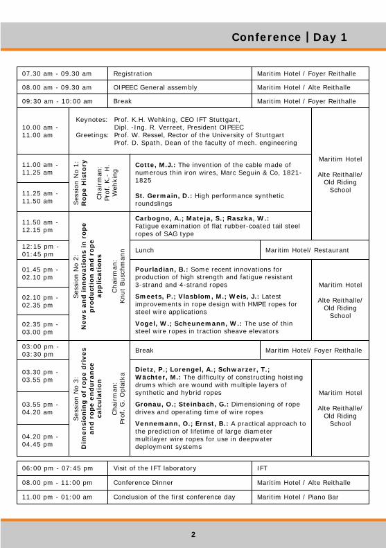
18 marzo 2009 - I° giorno di relazioni: Presentazione del I.F.T. (Institut fur Fordertechnik und Logistik) dell’Università di Stoccarda, specializzato nei sistemi di trasporto, per la parte direttamente interessante le funi (studi di fatica, metodi di controllo ed ispezione, metodi di calcolo, calcolo della vita tecnica delle funi, lavorazione delle funi, etc.) J.C. Weis, I.M.L. Ridge: W.A.J.Albert and his wire rope Celebrazione dei 175 anni della fune, inventata da Albert – percorso storico Cotte, M.J.: The invention of the cable made of numerous thin iron wires, Marc Seguin & Co, 1821-1825 Illustrazione del percorso storico dell’utilizzo delle funi in acciaio, costituite da fasci di fili paralleli, nelle strutture a funi portanti dei ponti sospesi. St. Germain, D.: High performance synthetic roundslings Funi sintetiche per alti carichi (es.1000tonn): tipologie, caratteristiche dei materiali e di produzione, campi di utilizzo, versatilità, controlli confronto con le funi in acciaio, Carbogno, A.; Mateja, S.; Raszka, W.: Fatigue examination of flat rubber-coated tail steelropes of SAG type Comportamento a fatica di funi piatte costituite da 2-4-8 funi in acciaio affiancate ed annegate in materiale plastico, a realizzare una fune piatta (per montacarichi o ascensori in miniere) Pourladian, B.: Some recent innovations for production of high strength and fatigue resistant 3-strand and 4-strand ropes Progressi nella produzione di funi in acciaio a tre o quattro trefoli, ai fini della distribuzione degli sforzi e del miglioramento della resistenza a fatica. Smeets, P.; Vlasblom, M.; Weis, J.: La test improvements in rope design with HMPE ropes for steel wire applications Innovazioni nella realizzazione di funi sintetiche in fibre di polietilene ad alta densità (HPME) – comportamento sugli argani e pulegge di deviazione – applicazioni marine, immerse nell’acqua – problemi di abrasione Vogel, W.; Scheunemann, W.: The use of thin steel wire ropes in traction sheave elevators Impiego di funicelle in acciaio molto piccole (4mm) sugli ascensori domestici, ai fini di ridurre ingombri e costi dei sistemi di sollevamento- comportamento a fatica.. Dietz, P.; Lorengel, A.; Schwarzer, T.; Wächter, M. : The difficulty of constructing hoisting drums which are wound with multiple layers of synthetic and hybrid ropes Problematiche di dimensionamento dei tamburi degli argani di sistemi di sollevamento, quando si avvolgono numerosi strati di funi sintetiche Gronau, O.; Steinbach, G.: Dimensioning of rope drives and operating time of wire ropes Dimensionamento di argani per sistemi di sollevamento – rottura a fatica delle funi in acciaio. Vennemann, O.; Ernst, B.: A practical approach to the prediction of lifetime of large diameter multilayer wire ropes for use in deepwater deployment systems Approccio sulla prevedibile durata di vita di funi di grosso diametro su piattaforme offshore
4
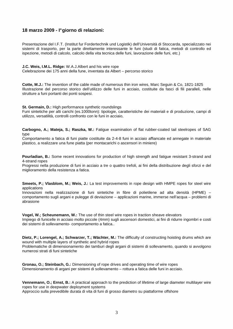
Visita al Laboratorio I.F.T. (Institut fur Forderte chnik und Logistik)
dell’Università di Stoccarda (vedi www.uni-stuttgart.de/ift)
Interno sala prove
Macchina di prova da 600kN
5
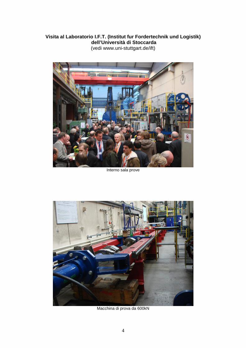
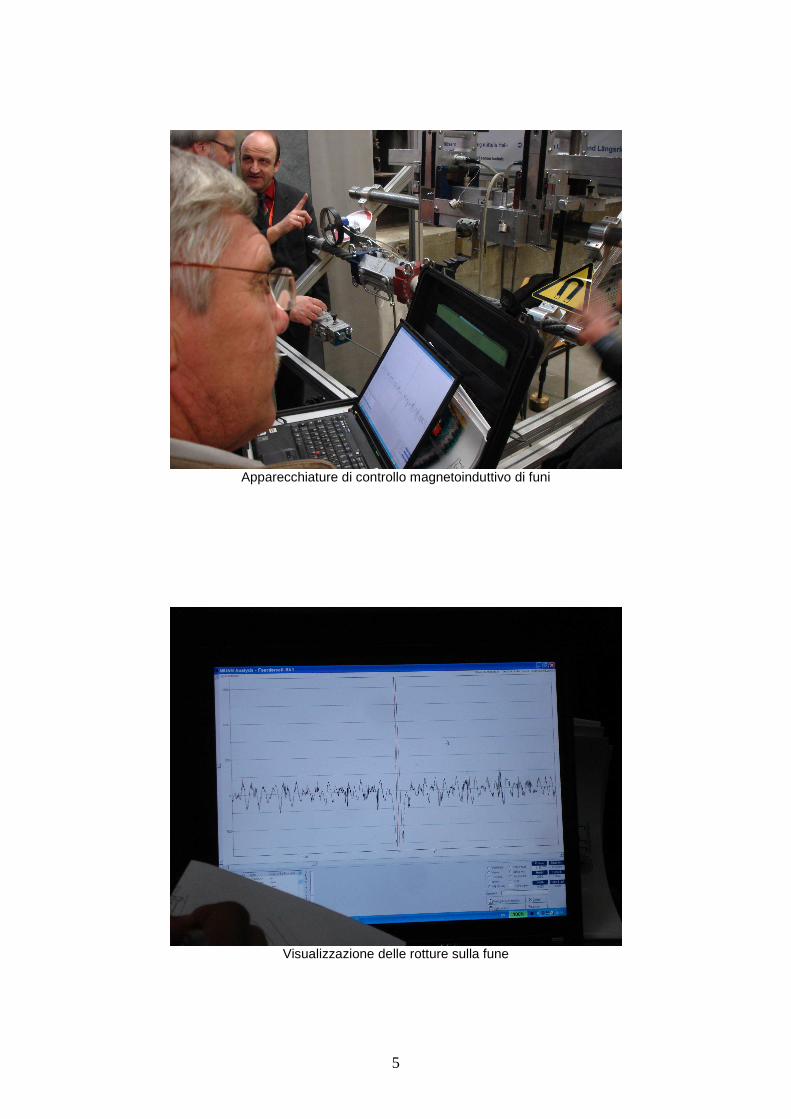
Apparecchiature di controllo magnetoinduttivo di funi
Visualizzazione delle rotture sulla fune

6
serie apparecchi di controllo funi Funi di grosso diametro in dotazione
macchine per prove a fatica sulle funi

7
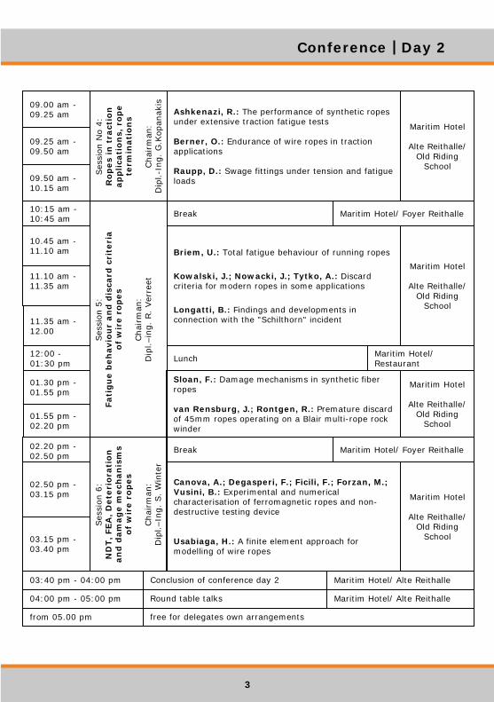
19 marzo 2009 - II° giorno di relazioni: Ashkenazi, R.: The performance of synthetic ropes under extensive traction fatigue tests Comportamento di funi sintetiche sotto prova di fatica Berner, O.: Endurance of wire ropes in traction applications Durata delle funi in applicazione di sistemi di sollevamento, con particolare riferimento al passaggio sugli argani di trazione e pulegge di deviazione Raupp, D.: Swage fittings under tension and fatigue loads Collegamenti di estremità delle funi di acciaio , realizzati con manicotto pressato :distribuzione degli sforzi e resistenza a fatica del collegamento Briem, U.: Total fatigue behaviour of running ropes Studio teorico degli sforzi sui fili componenti le funi che transitano sulle pulegge e comportamento a fatica sia su modello, che con riscontro sperimentale. Kowalski, J.; Nowacki, J.; Tytko, A.: Discard criteria for modern ropes in some applications Definizione di criteri di dismissione delle funi, con l’ausilio di un database contenente parametri di utilizzazione delle funi (cicli di carico, movimentazione, misura di diametri e passi sulla fune, catalogazione ispezioni visive e strumentali. Longatti, B.: Findings and developments in connection with the "Schilthorn" incident Esposizione del danneggiamento sulle funi portanti della funivia dello Schiltorn (CH), indagini effettuate e proposta di programma di ispezioni Sloan, F.: Damage mechanisms in synthetic fiber Ropes Fenomenologia del danno in funi sintetiche (variazioni di tensione, interazioni tra e fibre, abrasioni, fatica) van Rensburg, J.; Rontgen, R.: Premature discard of 45mm ropes operating on a Blair multi-rope rock winder Illustrazione di dismissione prematura di funi su montacarichi di miniera, dovuta alle eccessive pressioni trasversali tra gli strati di fune che si avvolgono sul tamburo dell’argano di movimentazione Canova, A.; Degasperi, F.; Ficili, F.; Forzan, M.; Vusini, B.: Experimental and numerical characterisation of ferromagnetic ropes and nondestructive testing device (vedi descrizione pagina seguente) Usabiaga, H.: A finite element approach for modelling of wire ropes Modellizzazione della fune agli elementi finiti (FEM), per la quantificazione delle azioni tra i fili, in funzione della tipologia delle funi
8
Relazione italiana presentata: Canova, A.; Degasperi, F.; Ficili, F.; Forzan, M.;V usini, B.: Experimental and numerical characterisation of ferromagnetic ropes and nondestructive testing device Prof. Aldo Canova: Dipartimento di Ingegneria Elettrica - Politecnico di Torino (Italy) Ing. Fabio Degasperi: Laboratorio Tecnologico Impianti a Fune (Latif) – Ravina di Trento, Trento (Italy) Ing. Franco Ficili e ing. Michele Forzan: Dipartimento di Ingegneria Elettrica - Università di Padova (Italy) Ing. Bruno Vusini AMC Instruments – Spin off del Politecnico di Torino (Italy) La relazione ha titolo: “Caratterizzazione numerica e sperimentale di funi ferromagnetiche e di apparecchiature per controllo magnetoinduttivo” Trattasi dell’unica relazione italiana presentata nelle ultime quattro edizioni della Conferenza Internazionale OIPEEC!! L’argomento del controllo magnetoinduttivo per la verifica dell’integrità delle funi in acciaio svolge un ruolo fondamentale per la valutazione delle condizioni delle funi in esercizio, ai fini dell’ammissibilità del loro mantenimento in opera o della necessità di sostituzione per raggiunti limiti di difettosità. Il metodo di controllo è ormai conosciuto nel settore delle funi in acciaio e la sua validità è consacrata: l’approccio ad una progettazione teorica di un dispositivo per il controllo magnetico è spinto dalla necessità di ottimizzare pesi ed ingombri delle apparecchiature, senza perdere la sensibilità del controllo, a rilevare i difetti La relazione affronta l’argomento della progettazione di un detector per questo tipo di controllo, con il seguente percorso:
a) caratterizzazione del materiale delle funi, cioè la risposta al campo magnetico indotto, ai fini della determinazione del campo necessario alla saturazione del materiale;
b) dimensionamento teorico del circuito magnetico e realizzazione di un prototipo di detector; c) calcolo teorico dell’andamento del campo magnetico nel detector, in assenza o in presenza di fune d) misura dell’induzione magnetica nella fune, tramite campioni appositamente predisposti; e) confronto e validazione del modello teorico, tramite le prove sperimentali.
Il LA.T.I.F. ha partecipato attivamente per la parte a) e d), e mettendo a disposizione le proprie conoscenze ed esperienza in materia di funi e di controlli magnetoinduttivi, argomenti trattati da decenni presso il Laboratorio. L’unione della parte teorica e della verifica sperimentale del modello ha portato ad un risultato di tutto rispetto, soprattutto per la metodica con la quale è stato affrontato l’argomento. La relazione, presentata dal prof. Canova è stata molto apprezzata, ritenuta molto interessante dagli ascoltatori ed ha stimolato interventi specifici, più delle altre relazioni presentate. I pochi tecnici che si occupano dell’argomento, molto sensibili alle novità, hanno richiesto chiarimenti a livello personale, a giornata conclusa. Dal punto di vista degli sviluppi futuri, il L.A.T.I.F. potrà avere ancora un ruolo significativo nella verifica di efficienza dei prototipi direttamente su funi difettose: da tempo sono stati predisposti spezzoni di fune finalizzati alla verifica di conformità degli apparecchi alla recente normativa europea UNI EN 12927-8. Questo permetterà di affiancare, al percorso teorico di dimensionamento, un costante riscontro sperimentale, offrendo l’opportunità di valutare gli effetti di modifiche e affinamenti sul prototipo, con contributo sostanziale all’ottimizzazione degli apparecchi stessi. E’ ormai consolidato che la maggior versatilità degli apparecchi di prova consente sia l’effettuazione di controlli più efficienti, che la loro esecuzione di tratti di fune oggi inaccessibili per problemi di ingombro. La partecipazione a questi studi permette al L.A,T.I.F. di essere presente nei gruppi di lavoro di redazione/modifica della normativa, con proposte supportate da risultati oggettivi. Stoccarda, 20 Marzo 2009 ing. Fabio Degasperi
9
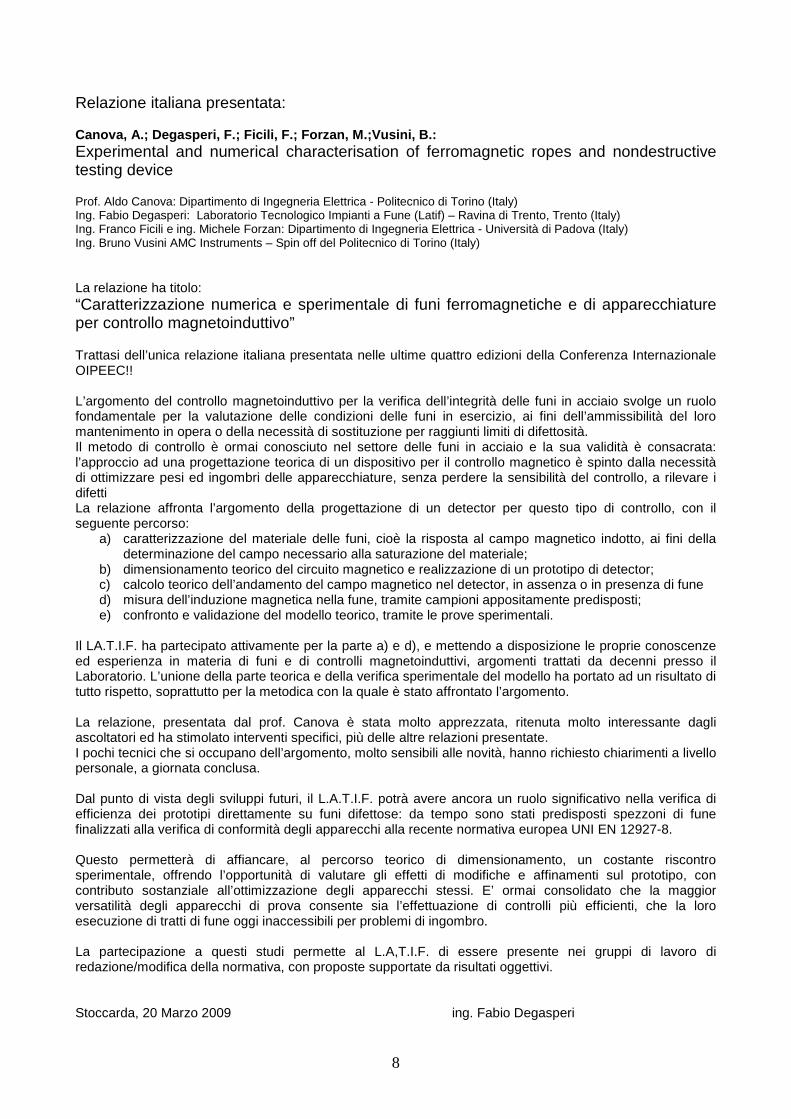
Documentazione fotografica di presentazione della r elazione
sala conferenze
avvio presentazione
10
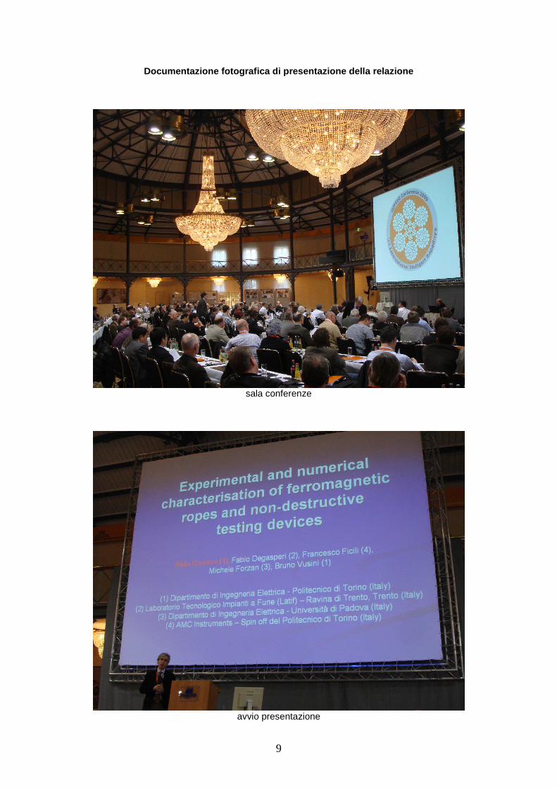
illustrazione del metodo di controllo
comportamento del materiale delle funi

11
andamento della permeabilità e risposta ai difetti
progettazione dell’apparecchio - modello
12
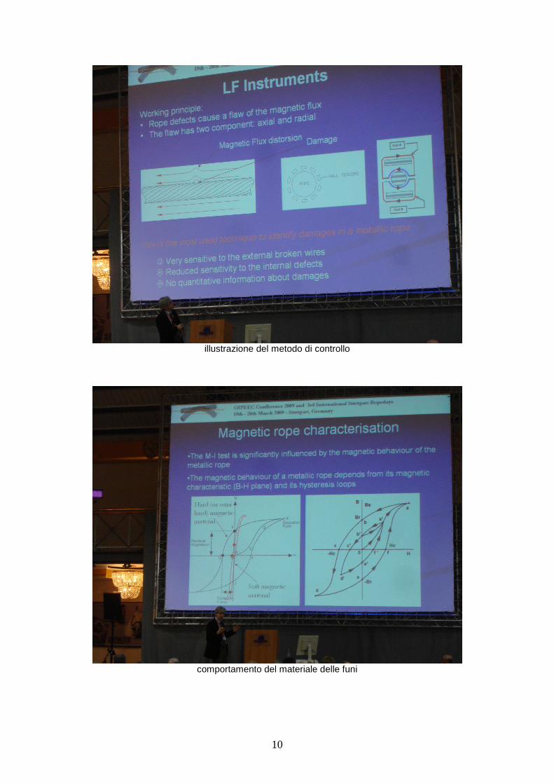
confronto tra modello e verifica sperimentale
conclusioni
13
RELAZIONE
Aldo Canova (1), Fabio Degasperi (2), Francesco Fic ili (4), Michele Forzan (3), Bruno Vusini (1) (1) Dipartimento di Ingegneria Elettrica - Politecnico di Torino (Italy) (2) Laboratorio Tecnologico Impianti a Fune (Latif) – Ravina di Trento, Trento (Italy) (3) Dipartimento di Ingegneria Elettrica - Università di Padova (Italy) (4) AMC Instruments – Spin off del Politecnico di Torino (Italy)
Experimental and numerical characterisation of ferr omagnetic ropes
and non-destructive testing devices
Summary
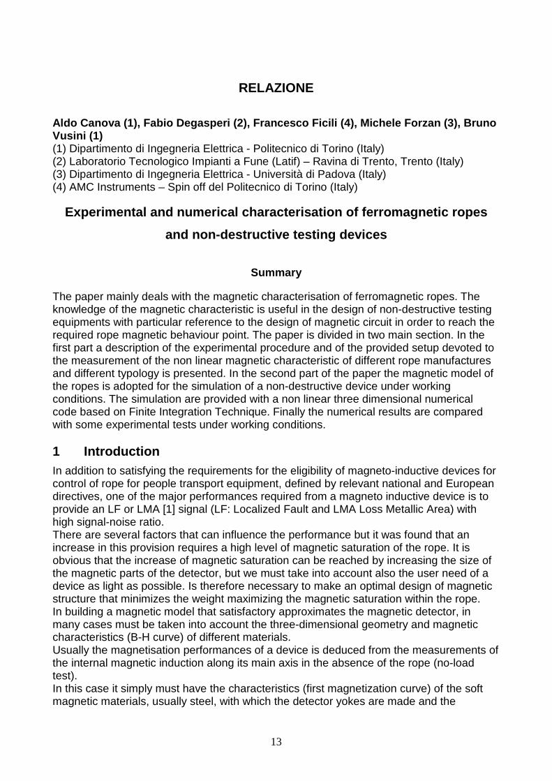
The paper mainly deals with the magnetic characterisation of ferromagnetic ropes. The knowledge of the magnetic characteristic is useful in the design of non-destructive testing equipments with particular reference to the design of magnetic circuit in order to reach the required rope magnetic behaviour point. The paper is divided in two main section. In the first part a description of the experimental procedure and of the provided setup devoted to the measurement of the non linear magnetic characteristic of different rope manufactures and different typology is presented. In the second part of the paper the magnetic model of the ropes is adopted for the simulation of a non-destructive device under working conditions. The simulation are provided with a non linear three dimensional numerical code based on Finite Integration Technique. Finally the numerical results are compared with some experimental tests under working conditions. 1 Introduction In addition to satisfying the requirements for the eligibility of magneto-inductive devices for control of rope for people transport equipment, defined by relevant national and European directives, one of the major performances required from a magneto inductive device is to provide an LF or LMA [1] signal (LF: Localized Fault and LMA Loss Metallic Area) with high signal-noise ratio. There are several factors that can influence the performance but it was found that an increase in this provision requires a high level of magnetic saturation of the rope. It is obvious that the increase of magnetic saturation can be reached by increasing the size of the magnetic parts of the detector, but we must take into account also the user need of a device as light as possible. Is therefore necessary to make an optimal design of magnetic structure that minimizes the weight maximizing the magnetic saturation within the rope. In building a magnetic model that satisfactory approximates the magnetic detector, in many cases must be taken into account the three-dimensional geometry and magnetic characteristics (B-H curve) of different materials. Usually the magnetisation performances of a device is deduced from the measurements of the internal magnetic induction along its main axis in the absence of the rope (no-load test). In this case it simply must have the characteristics (first magnetization curve) of the soft magnetic materials, usually steel, with which the detector yokes are made and the
14
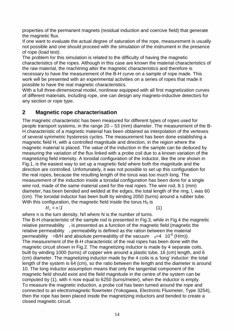
properties of the permanent magnets (residual induction and coercive field) that generate the magnetic flux. If one want to evaluate the actual degree of saturation of the rope, measurement is usually not possible and one should proceed with the simulation of the instrument in the presence of rope (load test). The problem for this simulation is related to the difficulty of having the magnetic characteristics of the ropes. Although in this case are known the material characteristics of the raw material, the machining alter the magnetic characteristics and therefore is necessary to have the measurement of the B-H curve on a sample of rope made. This work will be presented with an experimental activities on a series of ropes that made it possible to have the real magnetic characteristics. With a full three-dimensional model, nonlinear equipped with all first magnetization curves of different materials, including rope, one can design any magneto-inductive detectors for any section or rope type. 2 Magnetic rope characterisation The magnetic characteristic has been measured for different types of ropes used for people transport systems, in the range 20 – 53 (mm) diameter. The measurement of the B-H characteristic of a magnetic material has been obtained as interpolation of the vertexes of several symmetric hysteresis cycles. The measurement has been done establishing a magnetic field H, with a controlled magnitude and direction, in the region where the magnetic material is placed. The value of the induction in the sample can be deduced by measuring the variation of the flux linked with a probe coil due to a known variation of the magnetizing field intensity. A toroidal configuration of the inductor, like the one shown in Fig.1, is the easiest way to set up a magnetic field where both the magnitude and the direction are controlled. Unfortunately, it was not possible to set up this configuration for the real ropes, because the resulting length of the torus was too much long. The measurement of the induction inside a toroidal configuration has been done for a single wire rod, made of the same material used for the real ropes. The wire rod, 8.1 (mm) diameter, has been bended and welded at the edges, the total length of the ring, l, was 60 (cm). The toroidal inductor has been built by winding 2050 (turns) around a rubber tube. With this configuration, the magnetic field inside the torus H0 is 0H n I= ⋅ (1) where n is the turn density, N/l where N is the number of turns. The B-H characteristic of the sample rod is presented in Fig.3, while in Fig.4 the magnetic relative permeability �r is presented as a function of the magnetic field (magnetic the relative permeability �r permeability is defined as the ration between the material permeability �=B/H and absolute permeability of the vacuum �0=4�10-6 (H/m)). The measurement of the B-H characteristic of the real ropes has been done with the magnetic circuit shown in Fig.2. The magnetizing inductor is made by 4 separate coils, built by winding 1000 (turns) of copper wire around a plastic tube, 16 (cm) length, and 6 (cm) diameter. The magnetizing inductor made by the 4 coils is a ‘long’ inductor: the total length of the system is 64 (cm), so the ratio between the length and the diameter is around 10. The long inductor assumption means that only the tangential component of the magnetic field should exist and the field magnitude in the centre of the system can be computed by (1), with n now equal to 6250 (turns/meter), when the inductor is empty. To measure the magnetic induction, a probe coil has been turned around the rope and connected to an electromagnetic flowmeter (Yokogawa, Electronic Fluxmeter, Type 3254), then the rope has been placed inside the magnetizing inductors and bended to create a closed magnetic circuit.
15
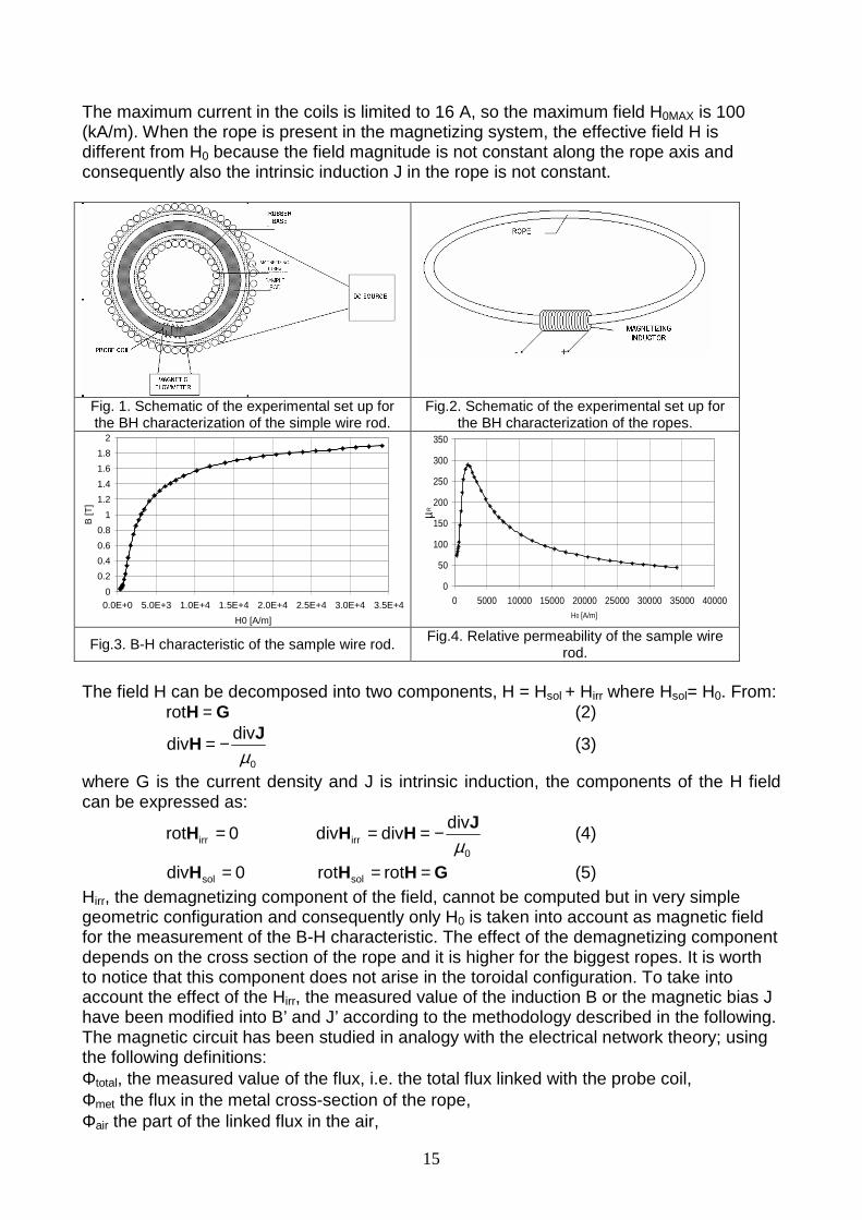
The maximum current in the coils is limited to 16 A, so the maximum field H0MAX is 100 (kA/m). When the rope is present in the magnetizing system, the effective field H is different from H0 because the field magnitude is not constant along the rope axis and consequently also the intrinsic induction J in the rope is not constant.
Fig. 1. Schematic of the experimental set up for the BH characterization of the simple wire rod.
Fig.2. Schematic of the experimental set up for the BH characterization of the ropes.
0
0.2
0.4
0.6
0.8
1
1.2
1.4
1.6
1.8
2
0.0E+0 5.0E+3 1.0E+4 1.5E+4 2.0E+4 2.5E+4 3.0E+4 3.5E+4
H0 [A/m]
B [T
]
0
50
100
150
200
250
300
350
0 5000 10000 15000 20000 25000 30000 35000 40000H0 [A/m]
µR
Fig.3. B-H characteristic of the sample wire rod. Fig.4. Relative permeability of the sample wire
rod. The field H can be decomposed into two components, H = Hsol + Hirr where Hsol= H0. From: GH =rot (2)
0
divdiv
µJ
H −= (3)
where G is the current density and J is intrinsic induction, the components of the H field can be expressed as:
0rot irr =H 0
irr
divdivdiv
µJ
HH −== (4)
0div sol =H GHH == rotrot sol (5) Hirr, the demagnetizing component of the field, cannot be computed but in very simple geometric configuration and consequently only H0 is taken into account as magnetic field for the measurement of the B-H characteristic. The effect of the demagnetizing component depends on the cross section of the rope and it is higher for the biggest ropes. It is worth to notice that this component does not arise in the toroidal configuration. To take into account the effect of the Hirr, the measured value of the induction B or the magnetic bias J have been modified into B’ and J’ according to the methodology described in the following. The magnetic circuit has been studied in analogy with the electrical network theory; using the following definitions: Φtotal, the measured value of the flux, i.e. the total flux linked with the probe coil, Φmet the flux in the metal cross-section of the rope, Φair the part of the linked flux in the air,
16
Scoil cross-section of the probe coil, Smet cross-section of the metal part of the rope, α filling factor of the coil (Smet/Scoil);
metr0met
dd
Sl⋅⋅
=ℜµµ
reluctance of an infinitesimal part of the metal part of the magnetic
circuit,
air0air
dd
Sl
⋅=ℜ
µreluctance of an infinitesimal part in air of the magnetic circuit.
The actual flux in the metal, Φmet, can be computed as:
metair
airmet dd
d
ℜ+ℜℜ
Φ=Φ tot (6)
From (6), using the coefficient α
α−= 1f and metSB ⋅=Φ 'met , the modified induction intensity
is: ( )
met
metcoiltot
met
mettot
S
SSH
S
SHB
−⋅⋅Φ=
⋅⋅⋅Φ= 0000 -f-
'µµ
(7)
The magnetic bias J’ is defined as: 0 0' 'J B Hµ= − ⋅ and:
met
coiltot
S
SHJ
⋅⋅Φ= 00-
'µ
(8)
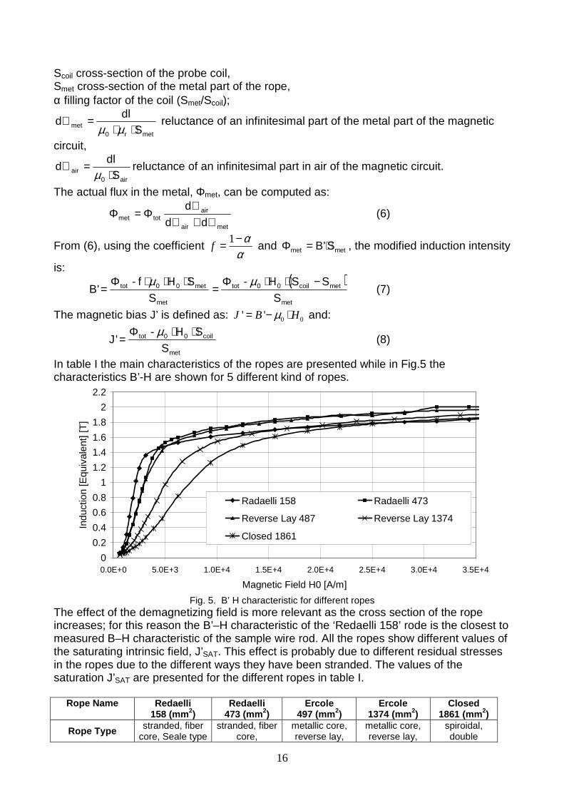
In table I the main characteristics of the ropes are presented while in Fig.5 the characteristics B’-H are shown for 5 different kind of ropes.
0
0.2
0.4
0.6
0.8
1
1.2
1.4
1.6
1.8
2
2.2
0.0E+0 5.0E+3 1.0E+4 1.5E+4 2.0E+4 2.5E+4 3.0E+4 3.5E+4
Magnetic Field H0 [A/m]
Indu
ctio
n [E
quiv
alen
t] [T
]
Radaelli 158 Radaelli 473
Reverse Lay 487 Reverse Lay 1374
Closed 1861
Fig. 5. B’ H characteristic for different ropes
The effect of the demagnetizing field is more relevant as the cross section of the rope increases; for this reason the B’–H characteristic of the ‘Redaelli 158’ rode is the closest to measured B–H characteristic of the sample wire rod. All the ropes show different values of the saturating intrinsic field, J’SAT. This effect is probably due to different residual stresses in the ropes due to the different ways they have been stranded. The values of the saturation J’SAT are presented for the different ropes in table I.
Rope Name
Redaelli 158 (mm2)
Redaelli 473 (mm2)
Ercole 497 (mm2)
Ercole 1374 (mm2)
Closed 1861 (mm2)
Rope Type stranded, fiber core, Seale type
stranded, fiber core,
metallic core, reverse lay,
metallic core, reverse lay,
spiroidal, double
17
Warrington-Seale type
external stranded
external stranded
external layer with Z-formed
wires Diameter (mm) 20 34 31 52 53
Construction 6(9+9+1)+PPC 6(12+6/6+1)
+PPC 12(6+1)+24
+18+ 12+6+1
12(6+1)+30 +24+18+12+6+
1
1+6+12+18 +24+30+32
+37 Number of wires 114 186 145 175 160
Lay Z/Z Z/Z - Z/S Z Metallic cross section (mm2) 158 473 497 1374.3 1861
Mass (kg/m) 1.43 4.28 4.35 11.6 15.4 External wire
diameter (mm) 1.61 2.18 2 3.46 h=4.20
Average Total Load (kN) 310 925 974 2800 3510
Saturated Magnetization
J’SAT (T) 1.9 2.1 2.1 1.93 1.92
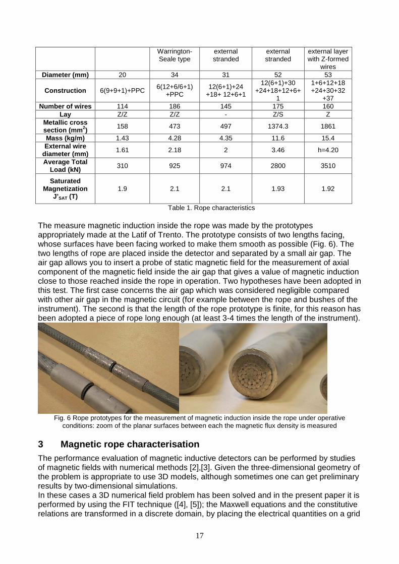
Table 1. Rope characteristics The measure magnetic induction inside the rope was made by the prototypes appropriately made at the Latif of Trento. The prototype consists of two lengths facing, whose surfaces have been facing worked to make them smooth as possible (Fig. 6). The two lengths of rope are placed inside the detector and separated by a small air gap. The air gap allows you to insert a probe of static magnetic field for the measurement of axial component of the magnetic field inside the air gap that gives a value of magnetic induction close to those reached inside the rope in operation. Two hypotheses have been adopted in this test. The first case concerns the air gap which was considered negligible compared with other air gap in the magnetic circuit (for example between the rope and bushes of the instrument). The second is that the length of the rope prototype is finite, for this reason has been adopted a piece of rope long enough (at least 3-4 times the length of the instrument).
Fig. 6 Rope prototypes for the measurement of magnetic induction inside the rope under operative
conditions: zoom of the planar surfaces between each the magnetic flux density is measured 3 Magnetic rope characterisation The performance evaluation of magnetic inductive detectors can be performed by studies of magnetic fields with numerical methods [2],[3]. Given the three-dimensional geometry of the problem is appropriate to use 3D models, although sometimes one can get preliminary results by two-dimensional simulations. In these cases a 3D numerical field problem has been solved and in the present paper it is performed by using the FIT technique ([4], [5]); the Maxwell equations and the constitutive relations are transformed in a discrete domain, by placing the electrical quantities on a grid
18
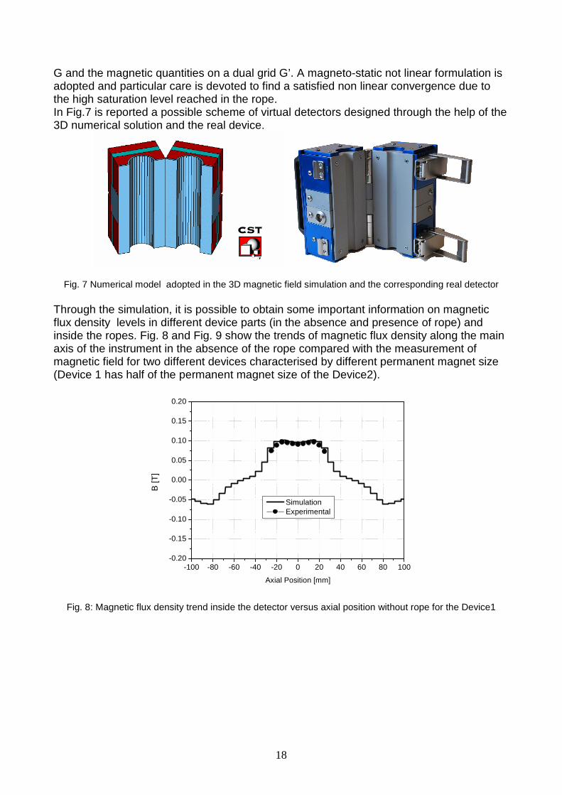
G and the magnetic quantities on a dual grid G’. A magneto-static not linear formulation is adopted and particular care is devoted to find a satisfied non linear convergence due to the high saturation level reached in the rope. In Fig.7 is reported a possible scheme of virtual detectors designed through the help of the 3D numerical solution and the real device.
Fig. 7 Numerical model adopted in the 3D magnetic field simulation and the corresponding real detector Through the simulation, it is possible to obtain some important information on magnetic flux density levels in different device parts (in the absence and presence of rope) and inside the ropes. Fig. 8 and Fig. 9 show the trends of magnetic flux density along the main axis of the instrument in the absence of the rope compared with the measurement of magnetic field for two different devices characterised by different permanent magnet size (Device 1 has half of the permanent magnet size of the Device2).
-100 -80 -60 -40 -20 0 20 40 60 80 100-0.20
-0.15
-0.10
-0.05
0.00
0.05
0.10
0.15
0.20
B [T
]
Axial Position [mm]
Simulation Experimental
Fig. 8: Magnetic flux density trend inside the detector versus axial position without rope for the Device1

19
-100 -80 -60 -40 -20 0 20 40 60 80 100-0.20
-0.15
-0.10
-0.05
0.00
0.05
0.10
0.15
0.20
B [T
]
Axial Position [mm]
Simulation Experimental
Fig. 9: Magnetic flux density trend inside the detector versus axial position without rope for the Dev. 2
Regarding the magnetic performances of the device under working conditions in Fig. 10 is reported the calculated magnetic flux density distribution along the rope axis compared with a measured value in the gap of the two rope parts (with a gap of 1.5 mm). The measured value inside the gap is lower to the value can be obtained inside the rope but it can provide an important indicator of the degree of saturation reached in the rope.
-100 -80 -60 -40 -20 0 20 40 60 80 100-1.5
-1.0
-0.5
0.0
0.5
1.0
1.5
2.0
B [T
]
Axial Position [mm]
Simulation without gap Simulation with gap of 1.5 (mm) Experimental with gap of 1.5 (mm)
Fig. 10: Magnetic flux density behaviour along the rope axis for the Device 2
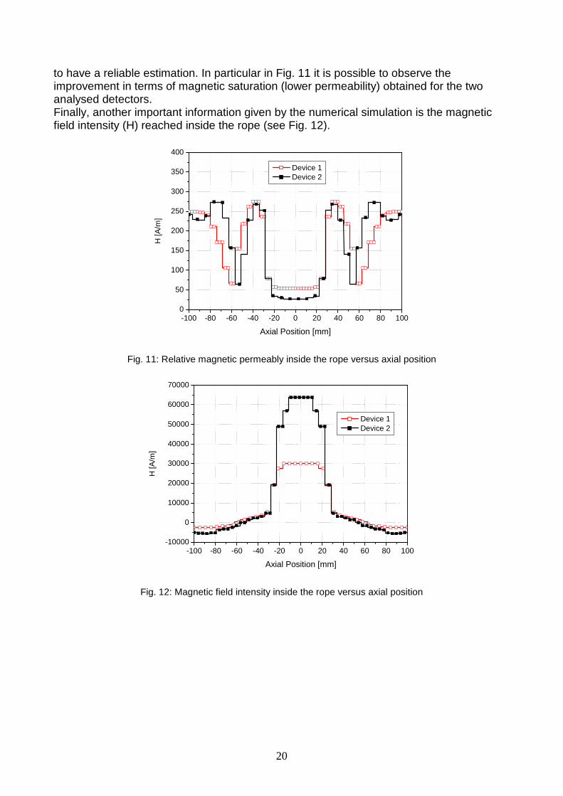
It is important to note that the saturation of the rope is the level of magnetic induction that can be reached inside the rope, but a better indicator is the value of the relative magnetic permeability: lower this value is, the more the rope is magnetically saturated. In particular the main goal is to obtain a lower value of the relative permeability in the central part of the rope where the LF magnetic probes (winding or hall sensors crowns) are placed to measure the leakage magnetic flux. It may have some relevance also the axial extension of the saturation zone. Of course this values cannot experimental measured but through the numerical model and the proper rope magnetic characterisation it is possible
20
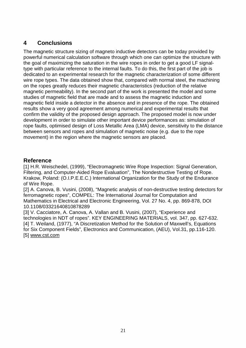
to have a reliable estimation. In particular in Fig. 11 it is possible to observe the improvement in terms of magnetic saturation (lower permeability) obtained for the two analysed detectors. Finally, another important information given by the numerical simulation is the magnetic field intensity (H) reached inside the rope (see Fig. 12).
-100 -80 -60 -40 -20 0 20 40 60 80 1000
50
100
150
200
250
300
350
400H
[A/m
]
Axial Position [mm]
Device 1 Device 2
Fig. 11: Relative magnetic permeably inside the rope versus axial position
-100 -80 -60 -40 -20 0 20 40 60 80 100-10000
0
10000
20000
30000
40000
50000
60000
70000
H [A
/m]
Axial Position [mm]
Device 1 Device 2
Fig. 12: Magnetic field intensity inside the rope versus axial position
21
4 Conclusions The magnetic structure sizing of magneto inductive detectors can be today provided by powerful numerical calculation software through which one can optimize the structure with the goal of maximizing the saturation in the wire ropes in order to get a good LF signal-type with particular reference to the internal faults. To do this, the first part of the job is dedicated to an experimental research for the magnetic characterization of some different wire rope types. The data obtained show that, compared with normal steel, the machining on the ropes greatly reduces their magnetic characteristics (reduction of the relative magnetic permeability). In the second part of the work is presented the model and some studies of magnetic field that are made and to assess the magnetic induction and magnetic field inside a detector in the absence and in presence of the rope. The obtained results show a very good agreement among numerical and experimental results that confirm the validity of the proposed design approach. The proposed model is now under development in order to simulate other important device performances as: simulation of rope faults, optimised design of Loss Metallic Area (LMA) device, sensitivity to the distance between sensors and ropes and simulation of magnetic noise (e.g. due to the rope movement) in the region where the magnetic sensors are placed. Reference [1] H.R. Weischedel, (1999), “Electromagnetic Wire Rope Inspection: Signal Generation, Filtering, and Computer-Aided Rope Evaluation”, The Nondestructive Testing of Rope. Krakow, Poland: (O.I.P.E.E.C.) International Organization for the Study of the Endurance of Wire Rope. [2] A. Canova, B. Vusini, (2008), “Magnetic analysis of non-destructive testing detectors for ferromagnetic ropes”, COMPEL: The International Journal for Computation and Mathematics in Electrical and Electronic Engineering, Vol. 27 No. 4, pp. 869-878, DOI 10.1108/03321640810878289 [3] V. Cacciatore, A. Canova, A. Vallan and B. Vusini, (2007), “Experience and technologies in NDT of ropes”. KEY ENGINEERING MATERIALS, vol. 347, pp. 627-632. [4] T. Weiland, (1977), “A Discretization Method for the Solution of Maxwell’s, Equations for Six Component Fields”, Electronics and Communication, (AEU), Vol.31, pp.116-120. [5] www.cst.com
““Innovative Ropes and Rope ApplicationsInnovative Ropes and Rope Applications””A celebration of 175 years of wire ropeA celebration of 175 years of wire rope
OIPEEC Conference 2009 OIPEEC Conference 2009
3rd International Stuttgart Ropedays
3rd International Stuttgart Ropedays
18th - 20th March 2009Stuttgart, Germany
ProgrammeProgramme
ORGANISATION INTERNATIONALE POUR L'ETUDE DE L'ENDURANCE DES CABLES INTERNATIONAL ORGANIZATION FOR THE STUDY OF THE ENDURANCE OF ROPESINTERNATIONALE ORGANISATION ZUM STUDIUM DER BETREIBSFESTIGKEIT VON SEILENORGANIZZAZIONE INTERNAZIONALE PER LO STUDIO DELLA FATICA DELLE FUNI
Institut für Fördertechnikund Logistik
together with
OIPEEC

Tuesday, March 17 – Welcome Reception
free for delegates own arrangementsfrom 07.00 pm
Maritim Hotel, LobbyRegistration and Welcome Drink05.00 pm - 07.00 pm
Conference schedule - Overview
(*) Contemporaneously to the registration OIPEEC will held its general assembly (from 8:00 am to 9:30 am). Members of OIPEEC are kindly asked to register at March 17 or before 8:00 am at Wednesday, March 18.
Wednesday, March 18 - Conference, Day 1
Thursday, March 19 - Conference, Day 2
Friday, March 20 - Technical and cultural excursion
Maritim Hotel, Foyer VenueRegistration07.30 am - 09.30 am
Maritim Hotel, Venue
OIPEEC General assembly (*)08.00 am - 09.30 am
Conference opening10.00 am - 11.00 am
Conference sessions11.00 am - 12.15 pm
Maritim Hotel, RestaurantLunch12.15 pm - 01.45 pm
Maritim Hotel, VenueConference sessions01.45 pm - 04.45 pm
Maritim Hotel, LobbyMeeting at Maritim Hotel06.00 pm - 06.15 pm
IFTVisit of IFT laboratory06.15 pm - 07.45 pm
Maritim Hotel, VenueConference Dinner08.00 pm - 11.00 pm
Maritim Hotel, VenueConference sessions09.00 am - 12.00
Maritim Hotel, RestaurantLunch12.00 - 01.30 pm
Conference sessions01.30 pm - 03.40 pm
Conclusion03.40 pm - 04.00 pm Maritim Hotel, Venue
Round table talks04.00 pm - 05.00 pm
Maritim Hotel, LobbyMeeting at Maritim Hotel09.00 am - 09.15 am
Excursion to the port of Stuttgart and the new Mercedes Benz museum
09.15 am - 04.30 pm
Maritim Hotel, LobbyReturn to Maritim Hotel04.30 pm - 05.00 pm
free for delegates own arrangementsfrom 07.00 pm
LocationContentTime
1
Maritim Hotel
Alte Reithalle/Old Riding
School
Maritim Hotel
Alte Reithalle/Old Riding
School
11.00 am -11.25 am
10.00 am -11.00 am
Cotte, M.J.: The invention of the cable made of numerous thin iron wires, Marc Seguin & Co, 1821-1825
St. Germain, D.: High performance synthetic roundslings
Break09:30 am - 10:00 am
Maritim Hotel / Alte ReithalleOIPEEC General assembly08.00 am - 09.30 am
Maritim Hotel / Foyer ReithalleRegistration 07.30 am - 09.30 am Ses
sion
No 1
: R
op
e H
isto
ry
Chai
rman
:Pro
f. K
.-H
. W
ehki
ng
11.25 am -11.50 am
11.50 am -12.15 pm
Carbogno, A.; Mateja, S.; Raszka, W.:Fatigue examination of flat rubber-coated tail steel ropes of SAG type
Ses
sion
No 2
: N
ew
s an
d in
novati
on
s in
rop
e
pro
du
ctio
n a
nd
rop
e
ap
plica
tio
ns
Chai
rman
:Knut
Busc
hm
ann
Dietz, P.; Lorengel, A.; Schwarzer, T.; Wächter, M.: The difficulty of constructing hoisting drums which are wound with multiple layers of synthetic and hybrid ropes
Gronau, O.; Steinbach, G.: Dimensioning of rope drives and operating time of wire ropes
Vennemann, O.; Ernst, B.: A practical approach to the prediction of lifetime of large diameter multilayer wire ropes for use in deepwater deployment systems
Ses
sion
No 3
: D
imen
sio
nin
g o
f ro
pe d
rives
an
d r
op
e e
nd
ura
nce
ca
lcu
lati
on
Chai
rman
:Pro
f. G
. O
pla
tka
03.55 pm -04.20 am
Break Maritim Hotel/ Foyer Reithalle
04.20 pm -04.45 pm
Conference Day 1
Keynotes: Prof. K.H. Wehking, CEO IFT Stuttgart,Dipl. -Ing. R. Verreet, President OIPEEC
Greetings: Prof. W. Ressel, Rector of the University of StuttgartProf. D. Spath, Dean of the faculty of mech. engineering
Lunch12:15 pm -01:45 pm
Maritim Hotel / Foyer Reithalle
Maritim Hotel
Alte Reithalle/Old Riding
School
Maritim Hotel/ Restaurant
01.45 pm -02.10 pm
02.10 pm -02.35 pm
02.35 pm -03.00 pm
03:00 pm -03:30 pm
03.30 pm -03.55 pm
Conference Dinner Maritim Hotel / Alte Reithalle08.00 pm - 11:00 pm
Conclusion of the first conference day Maritim Hotel / Piano Bar11.00 pm - 01:00 am
Visit of the IFT laboratory IFT06:00 pm - 07:45 pm
Pourladian, B.: Some recent innovations for production of high strength and fatigue resistant 3-strand and 4-strand ropes
Smeets, P.; Vlasblom, M.; Weis, J.: Latest improvements in rope design with HMPE ropes for steel wire applications
Vogel, W.; Scheunemann, W.: The use of thin steel wire ropes in traction sheave elevators
2
Conference Day 2
Briem, U.: Total fatigue behaviour of running ropes
Kowalski, J.; Nowacki, J.; Tytko, A.: Discard criteria for modern ropes in some applications
Longatti, B.: Findings and developments in connection with the "Schilthorn" incident
Ses
sion
5:
Fati
gu
e b
eh
avio
ur
an
d d
isca
rd c
rite
ria
of
wir
e r
op
es
Chai
rman
:D
ipl.–in
g.
R.
Ver
reet
Canova, A.; Degasperi, F.; Ficili, F.; Forzan, M.; Vusini, B.: Experimental and numerical characterisation of ferromagnetic ropes and non-destructive testing device
Usabiaga, H.: A finite element approach for modelling of wire ropes
Ses
sion
6:
ND
T, FEA
, D
ete
rio
rati
on
an
d d
am
ag
e m
ech
an
ism
s o
f w
ire r
op
es
Chai
rman
:D
ipl.–In
g.
S.
Win
ter
Ashkenazi, R.: The performance of synthetic ropes under extensive traction fatigue tests
Berner, O.: Endurance of wire ropes in traction applications
Raupp, D.: Swage fittings under tension and fatigue loads
Ses
sion
No 4
: R
op
es
in t
ract
ion
ap
plica
tio
ns,
rop
e
term
inati
on
s
Chai
rman
:D
ipl.-I
ng.
G.K
opan
akis
Maritim Hotel
Alte Reithalle/ Old Riding
School
10.45 am -11.10 am
11.10 am -11.35 am
11.35 am -12.00
03.15 pm -03.40 pm
Break Maritim Hotel/ Foyer Reithalle
Lunch12:00 -01:30 pm
Maritim Hotel
Alte Reithalle/ Old Riding
School
Maritim Hotel/ Restaurant
01.30 pm -01.55 pm
01.55 pm -02.20 pm
02.20 pm -02.50 pm
02.50 pm -03.15 pm
Conclusion of conference day 2 Maritim Hotel/ Alte Reithalle03:40 pm - 04:00 pm
free for delegates own arrangementsfrom 05.00 pm
Round table talks Maritim Hotel/ Alte Reithalle04:00 pm - 05:00 pm
Maritim Hotel
Alte Reithalle/Old Riding
School
09.25 am -09.50 am
09.50 am -10.15 am
Break Maritim Hotel/ Foyer Reithalle10:15 am -10:45 am
Sloan, F.: Damage mechanisms in synthetic fiber ropes
van Rensburg, J.; Rontgen, R.: Premature discard of 45mm ropes operating on a Blair multi-rope rock winder
09.00 am -09.25 am
3
Maritim Hotel
Alte Reithalle/ Old Riding
School
Welcome Reception
Attendance to the Welcome Reception on Tuesday is included in all delegate registration fees. It will be the first opportunity to network, meet industry colleagues and also to register to the conference in advance.
Conference exhibit
Next to the conference days an historical exhibit will be provided with focus on the wire rope of W.A.J. Albert of 1834.
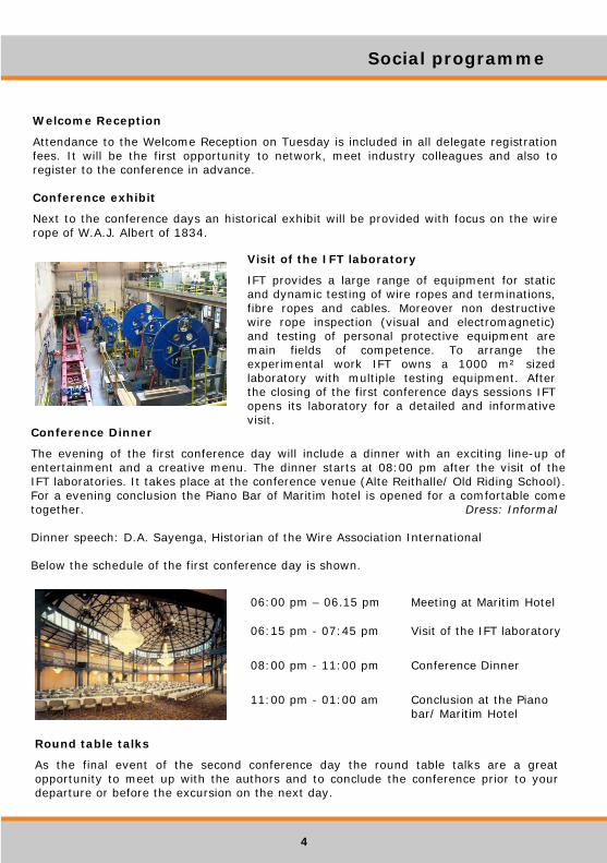
Conclusion at the Piano bar/ Maritim Hotel
11:00 pm - 01:00 am
Conference Dinner08:00 pm - 11:00 pm
Visit of the IFT laboratory06:15 pm - 07:45 pm
Meeting at Maritim Hotel06:00 pm – 06.15 pm
Social programme
Visit of the IFT laboratory
IFT provides a large range of equipment for static and dynamic testing of wire ropes and terminations, fibre ropes and cables. Moreover non destructive wire rope inspection (visual and electromagnetic) and testing of personal protective equipment are main fields of competence. To arrange the experimental work IFT owns a 1000 m² sized laboratory with multiple testing equipment. After the closing of the first conference days sessions IFT opens its laboratory for a detailed and informative visit.
Conference Dinner
The evening of the first conference day will include a dinner with an exciting line-up of entertainment and a creative menu. The dinner starts at 08:00 pm after the visit of the IFT laboratories. It takes place at the conference venue (Alte Reithalle/ Old Riding School). For a evening conclusion the Piano Bar of Maritim hotel is opened for a comfortable come together. Dress: Informal
Dinner speech: D.A. Sayenga, Historian of the Wire Association International
Below the schedule of the first conference day is shown.
Round table talks
As the final event of the second conference day the round table talks are a great opportunity to meet up with the authors and to conclude the conference prior to your departure or before the excursion on the next day.
4

Climate The weather in Stuttgart in March is alternating. Sunny and warm days change with cold and rainy days, so an umbrella may be usefull. For more information please visit www.wetteronline.de.
TaxiTaxies are called at 0049 711 19410. Most taxis accept major credit cards. If you want to pay with a credit card, let the driver know before beginning the trip.
Local public transportMaps of the local public transport net can be found at http://www.vvs.de.
Banks Normal banking hours are from 09:00 to 18:00 hrs, Monday to Friday. There are ATMs usually located in connection with a bank branch, which accept a variety of international credit cards. The cards accepted are indicated on the dispenser.
Lost or Stolen credit cardsIf your cards are stolen or lost, then you should cancel them immediately. In Germany there is a special number which you can dial for the most of the available credit cards (incl. Visa, Master Card, American Express). Phone: +49 116 116
EmergencyIn case of an emergency dial 110 for ambulance and police. Dial 112 for firedepartment. Foreign mobile users should dial the +49 711 before the emergency number above. English is fine - just speak as slowly and clearly as you can.
Contact
If you have any request, question or comment please contact us via:
e-mail: [email protected]: +49-711- 685 83771
Conference Management & Organising committee
In urgent cases please directly contact one of the organisers/ conference coordinators:
Dipl. -Ing. Jens Weis
phone: +49-711- 685 84198 or mobile +49-177 - 6861832e-mail: [email protected]
Dipl. -Ing. Sven Winter
phone: +49-711- 685 83787e-mail: [email protected]
The conference organising committee reserve the right to adjust or change the programme as necessary.
Useful information Contact
9 © Universität Stuttgart 2009 – Design & Layout Jens Weis, Konstantin Kühner, IFT Stuttgart