NORDIK ECO - gavri.es · Manual de instrucciones Instruktionshäfte Brugervejledning...
60
NORDIK ECO COD. 5.571.084.002 18/06/2018 Libretto istruzioni Instruction booklet Notice d’emploi et d’entretien Betriebsanleitung Manual de instrucciones Instruktionshäfte Brugervejledning Инструкция по эксплуатации
Transcript of NORDIK ECO - gavri.es · Manual de instrucciones Instruktionshäfte Brugervejledning...

NORDIK ECO
COD. 5.571.084.002 18/06/2018
Libretto istruzioniInstruction bookletNotice d’emploi et d’entretienBetriebsanleitung
Manual de instruccionesInstruktionshäfteBrugervejledningИнструкция по эксплуатации

Prima di usare il prodotto leggere attentamentele istruzioni contenute nel presente libretto.
Vortice non potrà essere ritenuta responsabileper eventuali danni a persone o cose causati
dal mancato rispetto delle indicazioni di seguitoelencate, la cui osservanza assicurerà invece ladurata e l’affidabilità, elettrica e meccanica,
dell’apparecchio.Conservare sempre questo libretto d’istruzioni.
Indice ITDescrizione ed impiego . . . . . . . . . . . . . . 4Attenzione - Avvertenze . . . . . . . . . . . . . . 4Utensili necessari al montaggio . . . . . . . 5Accessori in dotazione . . . . . . . . . . . . . . 5Installazione . . . . . . . . . . . . . . . . . . . . . . . 5Funzionamento. . . . . . . . . . . . . . . . . . . . . 5Pulizia . . . . . . . . . . . . . . . . . . . . . . . . . . . . . . . . . . . 5Collegamenti elettrici . . . . . . . . . . . . . . . . . . . . 5Smontaggio coppe. . . . . . . . . . . . . . . . . . 5Figure . . . . . . . . . . . . . . . . . . . . . . . . . . . . . . . . . . 20
Read the instructions contained in this bookletcarefully before using the appliance.
Vortice cannot assume any responsibility fordamage to property or personal injury resultingfrom failure to abide by the instructions given in
this booklet.Following these instructions will ensure a longservice life and overall electrical and mechanical
reliability.Keep this instruction booklet in a safe place.
Table of Contents ENDescription and use . . . . . . . . . . . . . . . . 6Warning - Caution . . . . . . . . . . . . . . . . . . 6Tools needed for assembly . . . . . . . . . . . 7Supplied accessories . . . . . . . . . . . . . . . . 7Installation . . . . . . . . . . . . . . . . . . . . . . . . 7Operation . . . . . . . . . . . . . . . . . . . . . . . . . 7Cleaning. . . . . . . . . . . . . . . . . . . . . . . . . . . . . . . . . 7Electrical connection . . . . . . . . . . . . . . . . . . . . 7Dismantling caps . . . . . . . . . . . . . . . . . . . 7Figures . . . . . . . . . . . . . . . . . . . . . . . . . . . . . . . . . 20
Avant d'utiliser le produit, lire attentivement lesinstructions contenues dans cette notice.
La société Vortice ne pourra être tenue pourresponsable des dommages éventuels causés auxpersonnes ou aux choses par suite du non-respect
desinstructions ci-dessous. Le respect de toutes les indications reportées dansce livret garantira une longue durée de vie ainsi que
la fiabilité électrique et mécanique del'appareil.onserver toujours ce livret d'instructions.
Index FRDescription et utilisation . . . . . . . . . . . . . 8Attention - Avertissement . . . . . . . . . . . . 8Outils nécessaires au montage . . . . . . . . 9Accessoires fournis . . . . . . . . . . . . . . . . . 9Installation . . . . . . . . . . . . . . . . . . . . . . . . 9Fonctionnement . . . . . . . . . . . . . . . . . . . . 9Nettoyage . . . . . . . . . . . . . . . . . . . . . . . . . . . . . . . 9Raccordements électriques . . . . . . . . . . . . . . 9Démontage carters. . . . . . . . . . . . . . . . . . 9Figures . . . . . . . . . . . . . . . . . . . . . . . . . . . . . . . . . 20
Vor Installation und Anschluss dieses Produktsmüssen die vorliegenden Anleitungenaufmerksam durchgelesen werden.
Vortice kann nicht für Personen- oderSachschäden zur Verantwortung gezogenwerden, die auf eine Nichtbeachtung derHinweise in dieser Betriebsanleitung zurückzuführen sind. Befolgen Sie alle
Anweisungen, um eine lange Lebensdauer sowiedie elektrische und mechanische Zuverlässigkeit
des Geräts zu gewährleisten.Diese Betriebsanleitung ist gut aufzubewahren.
Inhaltsverzeichnis DEBeschreibung und Gebrauch . . . . . . . . 10Achtung - Hinweis . . . . . . . . . . . . . . . . . 10Erforderliches Montagewerkzeug. . . . . . 11Im Lieferumfang Zubehör. . . . . . . . . . . . 11Installation . . . . . . . . . . . . . . . . . . . . . . . 11Funktionsweise. . . . . . . . . . . . . . . . . . . . 11Reinigung . . . . . . . . . . . . . . . . . . . . . . . . . . . . . . 11Schaltplan. . . . . . . . . . . . . . . . . . . . . . . . . . . . . . 11Ausbauen der Kappen . . . . . . . . . . . . . . 11Abbildungen. . . . . . . . . . . . . . . . . . . . . . . . . . . . 20

Innan produkten installeras och ansluts,läs noga dessa instruktioner.
Vortice kan ej hållas ansvarig för eventuellaskador på personer eller föremål orsakade avunderlåtenhet att uppfylla föreskrifterna somanges nedan, vilka om de däremot iakttasgaranterar tillförlitlig och säker drift av
apparaten under tiden. Bevara därför alltiddenna bruksanvisning för framtida bruk.
Før produktet installeres og tilsluttes, skal disseanvisninger læses grundigt. Vortice kan ikke hol-des ansvarlig for eventuelle skader på personereller ting forårsaget af manglende overholdelseaf disse forskrifter, der derimod er en garanti for
apparatets sikre og pålidelige funktion.Opbevar altid denne brugervejledning
Перед началом эксплуатации изделиявнимательно прочитайте указания,
приведенные в настоящей инструкции.Фирма Vortice не может считаться
ответственной за травмы илиматериальный ущерб, которые могут
быть вызваны несоблюдением положенийнижеприведенных указаний, в то время как
их выполнение явится гарантиейдлительного срока службы и механической и электрической надежности устройства.
Сохраняйте настоящую инструкцию.
Antes de utilizar el producto, leadetenidamente las instrucciones contenidas en
el presente manual. Vortice no se haceresponsable de posibles daños a personas o
cosas provocados por el incumplimiento de lasindicaciones que se describen a continuación,cuyo cumplimiento asegurará la duración yfiabilidad eléctrica y mecánica del aparato.
Conserve siempre este manual deinstrucciones.
Índice ESDescripción y uso . . . . . . . . . . . . . . . 12Atenciòn - Advertencia . . . . . . . . . . . 12Herramientas necesarias para el montaje . 13Accesorios . . . . . . . . . . . . . . . . . . . . . . . 13Instalación . . . . . . . . . . . . . . . . . . . . . . . 13Funcionamiento . . . . . . . . . . . . . . . . . . . 13Limpieza . . . . . . . . . . . . . . . . . . . . . . . . . . . . . . . 13Conexiones eléctricas . . . . . . . . . . . . . . . . 13Desmontaje de las copas. . . . . . . . . . . . 13Figuras . . . . . . . . . . . . . . . . . . . . . . . . . . . . . . . . . 20
Innehållsförteckning SVBeskrivning och användning . . . . . . . . . 14Let Op - Waarschuwing . . . . . . . . . . . . 14Verktyg som krävs för montering . . . . . 15Medföljande tillbehör . . . . . . . . . . . . . . . 15Installation . . . . . . . . . . . . . . . . . . . . . . . 15Funktion . . . . . . . . . . . . . . . . . . . . . . . . . 15Rengöring . . . . . . . . . . . . . . . . . . . . . . . . . . . . . . 15Elektriska anslutningar. . . . . . . . . . . . . . . . . . 15Montera ner kupa . . . . . . . . . . . . . . . . . . 15Figuren . . . . . . . . . . . . . . . . . . . . . . . . . . . . . . . . . 20
Indeks DABeskrivelse og anvendelse . . . . . . . . . . 16Pas på - Advarsel . . . . . . . . . . . . . . . . . 16Nødvendigt værktøj til monteringen . . . 17Medfølgende værktøj . . . . . . . . . . . . . . 17Installation . . . . . . . . . . . . . . . . . . . . . . . 17Funktion . . . . . . . . . . . . . . . . . . . . . . . . . 17Rengøring . . . . . . . . . . . . . . . . . . . . . . . . . . . . . . 17Elektriske forbindelser . . . . . . . . . . . . . . . . . . 17Afmontering af kupler. . . . . . . . . . . . . . . 17Figurerne . . . . . . . . . . . . . . . . . . . . . . . . . . . . . . . 20
Оглавление RUОписание и применение . . . . . . . . . . . 18Oсторожно - Вниманиe . . . . . . . . . . . . . 18Инструменты, необходимые для монтажа . 19Принадлежностиj . . . . . . . . . . . . . . . . . 19Установка. . . . . . . . . . . . . . . . . . . . . . . . 19Функционирование . . . . . . . . . . . . . . . . 19Чистка . . . . . . . . . . . . . . . . . . . . . . . . . . . . . . . . . 19Электрические подключения . . . . . . . . . . 19Демонтаж колпаков . . . . . . . . . . . . . . . 19Иллюстрации . . . . . . . . . . . . . . . . . . . . . . . . . . 20

Descrizione ed impiegoIl prodotto da lei acquistato è un apparecchioventilatore agitatore da soffitto reversibile contemperatura massima di funzionamento di 45°C.
Gli apparecchi della serieNORDIK ECO sono statiprogettati per un uso in ambientedomestico.Sono adatti anche per installazioni in ambitiCommerciali o Industriali purché le condizioniambientali non siano particolarmente aggressive(esempio ambienti corrosivi, polverosi, …).
• Non usare questo prodotto per una funzionedifferente da quella esposta in questo libretto.
• Dopo aver tolto il prodotto dall’imballo, assicurarsidella sua integrità; nel dubbio rivolgersi subito ad unCentro Assistenza Tecnica autorizzato Vortice.
• Non lasciare parti dell’imballo alla portata di bambinio persone diversamente abili.
• L’uso di qualsiasi apparecchio elettrico comportal’osservanza di alcune regole fondamentali, tra lequali:- non toccarlo con mani bagnate o umide- non toccarlo a piedi nudi.
• Non utilizzare l’apparecchio in presenza di sostanzeo vapori infiammabili come alcool, insetticidi,benzina, ecc.
• La parte inferiore delle pale deve risultare adun’altezza uguale o superiore a metri 2,70 dal pianodi calpestio (fig.1), nel caso di installazione inambito non residenziale, secondo le norme vigenti.
• Qualsiasi modifica venga apportata all’attaccopredisposto dalla fabbrica farà decadere la garanziae solleverà il costruttore da eventuali responsabilità
• Non apportare modifiche di alcun genereall’apparecchio.
• Ispezionare visivamente e periodicamente l’integritàdell’apparecchio. In caso di imperfezioni, nonutilizzare l’apparecchio e contattare subito unCentro di Assistenza Tecnica autorizzato Vortice.
• L’impianto elettrico a cui è collegato il prodotto deveessere conforme alle norme vigenti.
• L’apparecchio deve essere correttamente collegatoad un efficace impianto di messa a terra, comeprevisto dalle vigenti norme di sicurezza elettrica. Incaso di dubbio, richiedere un controllo accurato daparte di personale professionalmente qualificato.
• Collegare il prodotto alla rete di alimentazione/presaelettrica solo se la portata dell’impianto/presa èadeguata alla sua potenza massima. In casocontrario rivolgersi subito a personaprofessionalmente qualificata.
• Se il prodotto cade o riceve forti colpi farlo verificare
subito presso un Centro di Assistenza Tecnicaautorizzato Vortice.
• In caso di cattivo funzionamento e/o guasto,spegnere l’interruttore dell’apparecchio. Rivolgersisubito ad un Centro di Assistenza Tecnicaautorizzato e richiedere, per l’eventuale riparazione,l’uso di ricambi originali Vortice.
• Spegnere l’interruttore dell’apparecchio quando nonè utilizzato.
• Posizionare il prodotto ad un’adeguata distanza dapareti, oggetti,ecc.
• I dati elettrici della rete devono corrispondere aquelli riportati in targa A (fig.2).
4
ITALIANO
Attenzione:questo simbolo indica che è necessarioprendere precauzioni per evitare danni all’utente!
Avvertenza:questo simbolo indica che è necessarioprendere precauzioni per evitare danni al prodotto
!
Utensili necessari almontaggioFigura A
Accessori in dotazioneFigura B
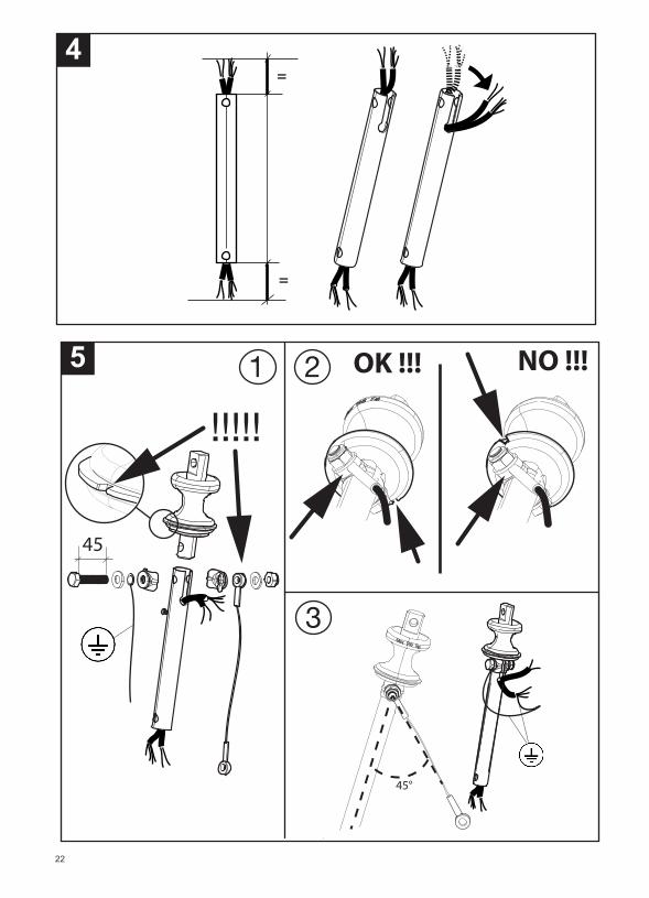
InstallazioneFigure: 4 ÷ 50Per l’installazione attenersi comunque a quantoesposto nel seguito.
1.Verificare che il soffitto di destinazione siastrutturalmente adeguato a sostenere il peso delprodotto.
2.Prestare attenzione a che i dispositivi di ancoraggionon compromettano la resistenza strutturale delsoffitto di destinazione.
3.Utilizzare tasselli in grado di garantire la tenuta sulmateriale del soffitto di destinazione
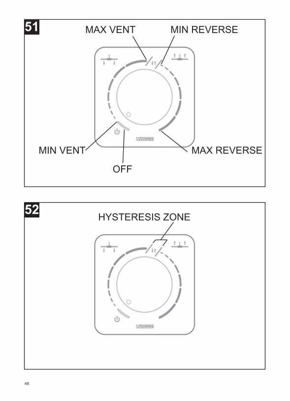
FunzionamentoAttenzione !!! Quanto descritto in questo capitolo èrelativo esclusivamente all’utilizzo del regolatoreVORTICE Cod.12829 POT-R. Il funzionamento èpossibile con altri potenziometri purchè abbiano leseguenti caratteristiche:1 - valore resistivo di 10kOhm2 - interruttore integrato oppure esterno (fig.57
L’accensione del ventilatore avviene tramitel’interruttore integrato nel potenziometro. Partendodalla posizione di riposo della manopola e ruotandolain senso orario, alla chiusura dell’interruttore siavvertirà uno scatto e poi, all’accensione delventilatore, un breve segnale acustico del buzzeraccompagnato da una accensione veloce del led.
L’impostazione della velocità è continua. La primametà del fondo scala del potenziometro è dedicataalla regolazione della velocità del prodotto inventilazione “standard” (aria spinta verso ilpavimento); la seconda metà del fondo scala èdedicata alla regolazione in modalità “reverse” (ariaspinta verso il soffitto). Il passaggio da ventilazione“standard” a ventilazione “reverse” viene sottolineatoda due brevi segnali acustici del buzzer e da dueaccensioni veloci del led mentre il passaggio daventilazione “reverse” a ventilazione “standard” èevidenziato da un breve segnale acustico del buzzere da una accensione veloce del led (fig.51).
Sul potenziometro è indicata (fig.52) una zona ditransizione (HYSTERESYS ZONE) corrispondente alpassaggio dal funzionamento in modalità ventilazione“standard” (alla velocità massima) al funzionamento inmodalità ventilazione “reverse” (in velocità minima).
Lo spegnimento, che avviene ruotandocompletamente in senso antiorario la manopola, vieneindicato da un segnale acustico lungo del buzzer e dauna accensione lunga del led.
Il prodotto può essere azionato a distanza con iltelecomando VORTICE Cod.21200 TELENORDIKECO e con il controllore Vort Delta T WIFI Cod. 21175. ATTENZIONE !Per utilizzare il TELENORDIK ECO e il Vort Delta TWIFI spegnere il potenziometro, se presente.
PuliziaFigure: 53 ÷ 56.Prima di effettuare qualsiasi operazione di pulizia o dimanutenzione, spegnere l’interruttore dell’apparecchio e staccare la sua eventuale spina dallarete d’alimentazione.
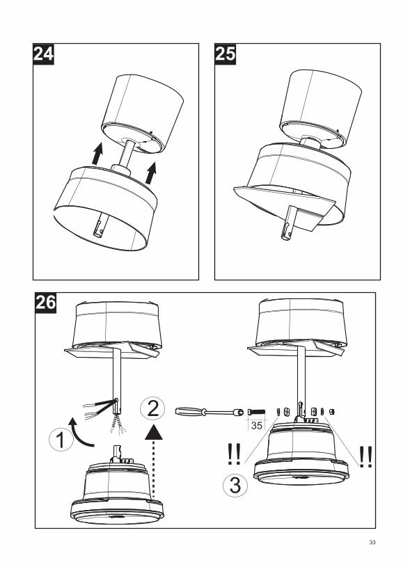
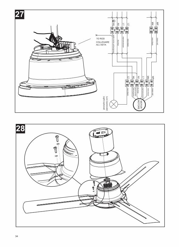
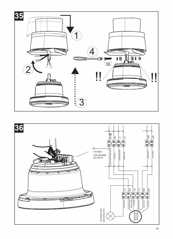
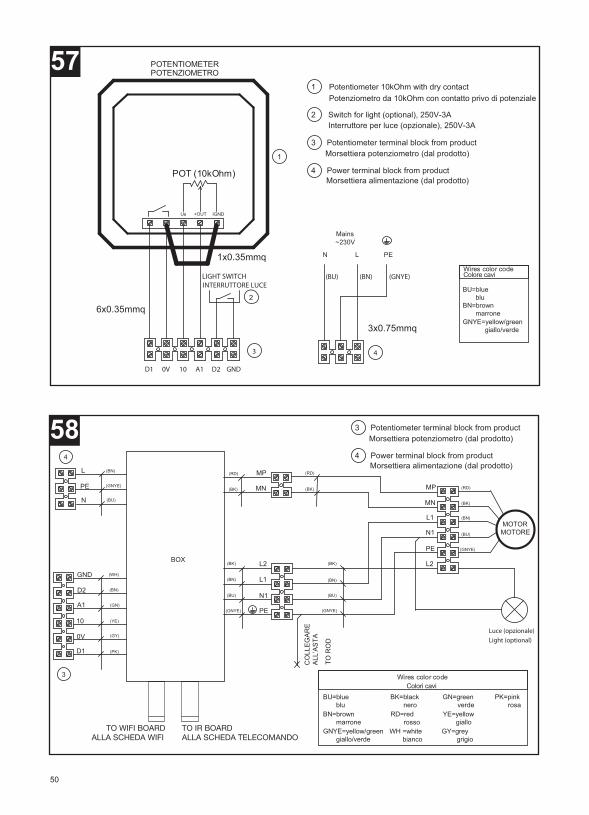
Collegamenti elettriciFigure: 57 ÷ 58
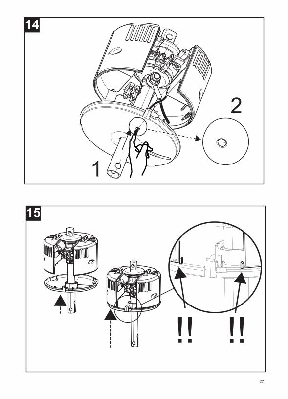
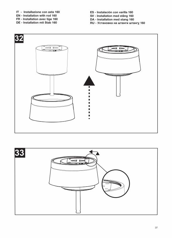
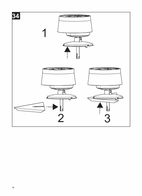
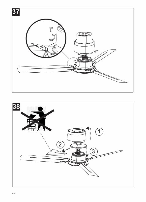
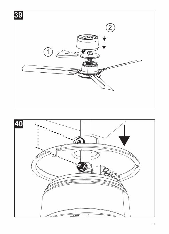
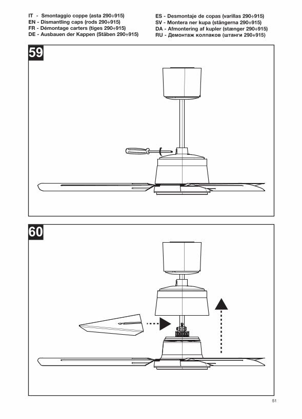
Smontaggio coppe Figure: 59 ÷ 62 (aste 290÷915)
Figure: 63 ÷ 68 (asta 160)
5
ITALIANO
6
Description and useThe product you have purchased is a reversible cei-ling agitator fan unit with a maximum operating tem-perature of 45°C.
NORDIK ECO series units havebeen designed for householduse.NORDIK ECO series units have been designed forhousehold installation and use. They are also suitablefor installations in Commercial or Industrial areas pro-vided environmental conditions are not particularlyaggressive (i.e. corrosive, dusty environments, etc.).
• Do not use this product for functions other thanthose described in the instruction booklet.
• After having removed the product from its packing,ensure that it is complete and undamaged: if indoubtcontact Vortice Service Centre.
• Do not leave packaging within the reach of childrenor differently able persons.
• Certain fundamental rules must be observed whenusing any electrical appliance: - Never touch appliances with wet or damp hands- Never touch appliances while barefoot
• Do not use the appliance where flammable vapoursare present (spirit, insecticides, petrol, etc.).
• To conform with applicable standards, the bottomedges of the fan blades must be at a height of atleast 2.7 metres or more from the floor (fig.1) in non-residential premises.
• Unauthorised changes to the factory set fittingshallinvalidate the guarantee and entitle the manu-facturer to disclaim any whatsoever liability.
Do not make modifications of any kind to thisappliance.
• Regularly inspect the appliance for visible defects. Ifany faults are found, do not operate the appliancebut contact Vortice Service Centre.
• The electrical mains to wich the unit is connectedmust conform to current standard.
• The appliance must be properly connected to anelectrical system in compliance with the applicableregulations and equipped with an efficient earthingsystem. If in doubt, have a qualified electricianperform a thorough check.
• The electrical power source to which the productisto be connected must be able to provide themaximum amount of electrical power required bythe product.If it cannot do this, contact an electricianfor appropriate remedial action.
• Should the appliance be dropped or suffer a heavyblow, have it checked immediately by Vortice.
• If the appliance does not function correctly ordevelops a fault, turn it off and contact Vorticeimmediately. Ensure that only genuine originalVortice spares are used for any repairs.
• Do not leave the appliance on unnecessarily: whenthe appliance is not in use, turn the switch to off.
• Place the unit at a suitable distance fromwalls,objects, etc.
• Specifications for the power supply mustcorrespond to the electrical data on data plate A(fig.2).
ENGLISH
Warning:this symbol indicates that care mustbe taken to avoid injury to the user!
Caution:this symbol indicates that care must be taken to avoid damaging the appliance
!

Tools needed for assemblyFigure A
Supplied accessoriesFigure B
InstallationFigures: 4 ÷ 50Please follow the instructions below for installation. 1. Make sure that the ceiling where the unit is to beinstalled is structurally sound to support the weightof the product. 2. Be careful that the anchoring devices do not com-promise the structural resistance of the ceilingwhere the unit is to be installed. 3. Use dowels that can ensure material stays grippedto the ceiling where the unit is to be installed.
OperationCaution!!! The information described in this chapteronly relates to use of the VORTICE Code 12829POT-R regulator. Operation is possible with otherpotentiometers provided they have the following cha-racteristics:1 - Resistive value 10kOhm2 - Integrated or external switch (fig.57)
Fans are turned on by means of a switch integratedinto the potentiometer. Start from the stand-by posi-tion on the knob and turn it clockwise. You will heara click when the switch closes and then, when the fanis switched back on, you will hear a brief buzzer toneaccompanied by a quick ignition of the LED.
The speed setting is continuous. The first half of thepotentiometer full scale is dedicated to adjusting pro-duct speed in "standard" ventilation (air pushedtoward the floor). The second half of the full scale isdedicated to "reverse" mode adjustment (air pushedtoward the ceiling). Fan passage from "standard"ventilation to "reverse" ventilation is highlighted bytwo short buzzer tones and two quick ignitions of theLED, while passage from "reverse" ventilation to"standard" ventilation is highlighted by a brief buzzertone and a quick ignition of the LED (fig.51).
A transition zone (HYSTERESYS ZONE) is indicatedon the potentiometer (fig.52), corresponding to pas-sage from "standard" ventilation mode operation (atmaximum speed) to "reverse" ventilation mode ope-ration (minimum speed).
Shut-down occurs by completely rotating the knob inthe counter-clockwise direction. A long buzzer toneand a long LED ignition will indicate shut-down.
The product can be remotely operated by means of
the VORTICE Code 21200 TELENORDIK ECO remotecontrol, and the remote controller unit Vort Delta TWIFI Code 21175.CAUTION!Switch off the potentiometer if present to use the“TELENORDIK ECO” and the “Vort Delta T WIFI”.
CleaningFigures: 53 ÷ 56.Before performing any cleaning or maintenance ope-rations, turn the unit switch off and disconnect itsplug from the power supply.
Electrical connectionsFigures: 57 ÷ 58
Dismantling capsFigures: 59 ÷ 62 (rods 290÷915)Figures: 63 ÷ 68 (rod 160)
7
ENGLISH
estbranché doit être conforme aux normes envigueur.
• L'appareil doit être branché correctement à uneinstallation électrique conforme aux normes envigueur et être équipé d'un système efficace de miseà la terre. Dans le doute, demander à du personnelprofessionnellement qualifié d'effectuer un contrôlesoigné.
• Brancher l’appareil au réseau d’alimentation/à laprise électrique uniquement si la portéedel’installation/prise est adaptée à la puissancemaximum.Dans le cas contraire, s’adresserimmédiatement à une personne professionnellementqualifiée.
• Si l'appareil tombe ou reçoit des coups violents, lefaire vérifier immédiatement auprès d'un Serviceaprès-vente agréé Vortice
• En cas de dysfonctionnement et/ou de panne,éteindre l'appareil et s'adresser immédiatement à unService après-vente agréé Vortice;.exiger, en cas deréparation, l'emploi de pièces détachées originalesVortice.
• Couper l’interrupteur de l’appareil quand onnel’utilise pas.
• Veiller à maintenir une distance suffisanteentrel’appareil et les parois ou autres éléments.
• Les données électriques du réseau doiventcorrespondre à celles inscrites sur la plaque A (Fig.2).
Description et utilisationLe produit que vous avez acheté est un ventilateur deplafond réversible avec une température de fonction-nement maximale de 45 ° C .
Les appareils de la série NORDIKECO ont été conçus pour une uti-lisation dans un environnementdomestique.Les appareils de la série NORDIK ECO ont été con-çus pour une installation et une utilisation dans unenvironnement domestique. Il est également adaptépour des installations dans des contextesCommerciaux ou Industriels si les conditions environ-nementales ne sont particulièrement agressives (parexemple, milieux corrosifs, poussiéreux, ...).
• Ne pas utiliser ce produit pour un usage autre quecelui décrit dans ce livret.
• Contrôler l'intégrité de l'appareil après l'avoir sortide son emballage : dans le doute, s'adresserimmédiatement à un Service après-vente agrééVortice.
• Placer les éléments de l'emballage hors de portéedes enfants ou des personnes handicapées.
• L'utilisation de tout appareil électrique requiertl'observation de quelques règles fondamentalesdont, entre autres :- ne pas toucher l'appareil avec les mains mouilléesou humides- ne pas toucher l'appareil pieds nus
• ne pas utiliser l'appareil en présence de substancesou de vapeurs inflammables telles que l'alcool, lesinsecticides, l'essence, etc.
• La partie inférieure des pales doit se trouver à unehauteur égale ou supérieure à 2,70 mètres de lasurface de piétinement (fig.1) en cas d'installationdans un milieu non résidentiel, selon les normes envigueur.
• Toute modification apportée au système de fixationd’origine annule la garantie et décharge lefabricantde toute responsabilité.
• Ne modifier l'appareil en aucune façon.• Contrôler visuellement et périodiquement l'intégritédu produit. En cas de défectuosité, ne pas utiliserl'appareil et contacter immédiatement un Serviceaprès-vente agréé Vortice.
• L’installation électrique sur laquelle le produit
8
FRANÇAIS
Attention:ce symbole indique la nécessité de prendrequelques précautions pour la sécurité de l‘utilisateur
!
Avertissement:ce symbole indique la nécessité de prendrequelques précautions pour la sécurité du produit
!

Outils nécessaires au montageFigure A
Accessoires fournisFigure B
InstallationFigures : 4 ÷ 50Suivre les indications mentionnées ci-dessous pourl'installation : 1.Vérifier que le plafond de destination soit structurel-lement adapté pour soutenir le poids du produit.
2.Faire attention à ce que les dispositifs de fixation necompromettent pas la résistance structurelle duplafond de destination.
3.Utiliser des chevilles en mesure de garantir le main-tien du matériel sur le plafond de destination.
FonctionnementAttention ! Les descriptions de ce chapitre concer-nent exclusivement l'utilisation du régulateur VORTI-CE Cod.12829 POT-R. Le fonctionnement est pos-sible avec d'autres potentiomètres ayant les caracté-ristiques suivantes :1 - charge résistive de 10kOhm2 - interrupteur intégré ou externe (fig.57)
Le démarrage du ventilateur se fait au moyen de l'in-terrupteur intégré dans le potentiomètre. En partantde la position de repos de la poignée et en la tour-nant dans le sens des aiguilles d'une montre, undéclic se produira à la fermeture de l'interrupteur puisun bref signal acoustique de l'avertisseur sonoreaccompagné d'un allumage rapide de la led audémarrage du ventilateur.
La programmation de la vitesse est continue. La pre-mière moitié du fond d'échelle du potentiomètre estdédiée au réglage de la vitesse du produit en ventila-tion «standard» (air poussé vers le sol) ; la deuxièmemoitié du fond d'échelle est dédiée au réglage enmodalité «inverse» (air poussé vers le plafond). Lepassage de ventilation «standard» à ventilation«inverse» est indiqué par deux signaux acoustiquesbrefs de l'avertisseur sonore et par deux allumagesrapides de la led alors que le passage de ventilation«inverse» à ventilation «standard» est indiqué par unbref signal acoustique de l'avertisseur sonore et parun allumage rapide de la led (fig.51).
Sur le potentiomètre est indiquée (fig.52) une zone detransition (HYSTERESYS ZONE) correspondant aupassage du fonctionnement en modalité ventilation«standard» (à la vitesse maximale) au fonctionnementen modalité ventilation «inverse» (à la vitesse minima-le).
L'arrêt qui a lieu en tournant complètement la poi-gnée dans le sens contraire des aiguilles d'une mon-tre, est indiqué par un long signal acoustique del'avertisseur sonore et par un long allumage de la led.
Le produit peut être actionné à distance avec la télé-commande VORTICE Cod.21200 TELENORDIK ECOet avec l’unité de contrôle Vort Delta T WIFI, code21175. ATTENTION !Pour utiliser "TELENORDIK ECO" et "Vort Delta TWIFI", éteindre le potentiomètre si présent.
NettoyageFigures : 53 ÷ 56Avant toute opération de nettoyage ou entretien,éteindre l'interrupteur de l'appareil et débrancher saprise éventuelle.
Raccordements électriquesFigures : 57 ÷ 58
Démontage cartersFigures : 59 ÷ 62 (tiges 290 ÷ 915)Figures : 63 ÷ 68 (tige 160)
9
FRANÇAIS
Fachpersonal vornehmen.• Das Produkt nur dann an das Stromnetzanschließen, wenn die Stromfestigkeit derAnlage/Steckdose für die maximale Leistunggeeignet ist. Sollte dies nicht der Fall sein, so sollteman sich sofort an einen Fachmann wenden.
• Fällt das Gerät hin oder wurde es starken Stößenausgesetzt, muss es sofort von einem Vortice-Vertragshändler überprüft werden.
• Das Gerät im Störungsfall oder bei mangelhafterFunktion mit dem Schalter ausschalten. WendenSie sich unverzüglich an eine autorisierteKundendienststelle und verlangen Sie im Fall einernotwendigen Reparatur den Einsatz von VorticeOriginal- Ersatzteilen.
• Den Schalter des Geräts ausschalten, wenn dasGerät nicht benutzt wird.
• Es muss ein ausreichender Abstand vonWänden,Objekten usw.vorgesehen werden.
• Die elektrischen Daten der Netzversorgung müssenden Angaben auf dem Typenschild A entsprechen(Abb.2).
Erforderliches
Beschreibung und GebrauchDas von Ihnen gekaufte Produkt ist ein reversiblerDecken-Ventilator mit maximaler Betriebstemperaturvon 45 ° C.
Die Geräte der Serie NORDIKECO wurden für denHausgebrauch konzipiert.Die Geräte der Serie NORDIK ECO wurden für eineHausinstallation und -gebrauch entwickelt. Es eignetsich auch Installationen in Gewerbe- undIndustrieumgebungen, vorausgesetzt, sie sind nichtübermäßig aggressiv (z.B. korrosive, staubigeUmgebungen usw.).
• Dieses Gerät darf nur für den Verwendungszweckeingesetzt werden, der in der vorliegenden Anleitungangegeben ist.
• Das Gerät nach dem Auspacken aufTransportschäden oder andere Mängel untersuchenund im Zweifelsfall sofort einen Vortice-Vertragshändler verständigen.
• Das Verpackungsmaterial entsorgen und nicht inReichweite von Kindern und anderen Personen, diesich damit schaden könnten, lassen.
• Beim Einsatz von Elektrogeräten jeder Art müsseneinige Grundregeln stets beachtet werden, darunterim einzelnen:- nicht mit nassen oder feuchten Händen berühren - nicht barfuß berühren.
• Das Gerät nicht in der Nähe entflammbarer Stoffeoder Dämpfe wie Alkohol, Insektizide, Benzin usw.verwenden.
• Handelt es sich nicht um ein Wohngebäude, mussder untere Teil der Rotorblätter den geltendenVorschriften entsprechend mindestens 2,70 m vomFußboden entfernt sein (Abb. 1).
• Jede Veränderung, die an der werkseitigvorgesehenen Aufhängung vorgenommen wird,führt zur Verlöschung der Garantie und entbindetden Hersteller von eventuellenHaftungsansprüchen.
• Keine Änderungen am Gerät vornehmen.• Den einwandfreien Zustand des Gerätes regelmäßigüberprüfen. Sollten Defekte festgestellt werden, dasGerät auf keinen Fall benutzen und sofort einenVortice-Vertragshändler verständigen.
• Die Elektroanlage, an die das Produktangescholossen ist, muß den geltendenVorschriften entsprechen.
• Das Gerät ist sachgerecht mit einer wirksamenErdungs zu verbinden, wie von den einschlägigenelektrotechnischen Sicherheitsbestimmungengefordert. Lassen Sie im Zweifelsfall eine sorgfältigeKontrolle der Elektroanlage durch qualifiziertes
10
DEUTSCH
Achtung:dieses Symbol zeigt Vorsichtsmaßnahmen anum Schäden am Bediener zu vermeiden!
Hinweis:dieses Symbol zeigt Vorsichtsmaßnahmen anum Schäden am Gerät zu vermeiden!
MontagewerkzeugAbbildung A
Im Lieferumfang ZubehörAbbildung B
InstallationAbbildungen: 4 ÷ 50Halten Sie sich zur Installation an nachstehendenAnweisungen. 1. Stellen Sie sicher, dass die Decke strukturell geei-gnet ist, um dem Gewicht des Geräts Stand zu hal-ten. 2. Stellen Sie sicher, dass dieVerankerungsvorrichtungen die strukturelleFestigkeit der Decke nicht beeinträchtigen. 3. Verwenden Sie Dübel, die den Halt des Geräts ander Decke gewährleisten
FunktionsweiseAchtung!!! Die Beschreibungen in diesem Kapitelrichten sich ausschließlich an die Verwendung desReglers VORTICE Cod.12829 POT-R. Der Betriebist auch mit anderen Potentiometern möglich, sofernsie folgende Merkmale aufweisen:1 - Widerstand 10kOhm2 - Eingebauter oder externer Schalter (Abb. 57)
Das Einschalten des Ventilators erfolgt über den imPotentiometer integrierten Schalter. Von derRuheposition aus dreht man den Drehgriff imUhrzeigersinn, bis man beim Schließen des Schaltersein Klicken hört, Danach ertönt beim Anlaufen desVentilators ein kurzer Signalton des Summers, dieLed leuchtet einmal kurz
Die Geschwindigkeitseinstellung erfolgt stufenlos.Die erste Hälfte des Messbereichs desPotentiometers dienst zurGeschwindigkeitsregulierung des Produkts in„Standardbelüftung“ (Luftstrom Richtung Boden); diezweite Hälfte des Messbereichs dient zurRegulierung des „Umkehrbetriebs“ (LuftstromRichtung Decke). Der Übergang von„Standardbelüftung“ zur „Umkehrbelüftung“ wirddurch zwei kurze Signaltöne des Summers und durchzweimal schnelles Blinken der Led angezeigt, derÜbergang von „Umkehrbelüftung“ auf„Standardbelüftung“ wird durch einen kurzenSignalton des Summers und durch einmal schnellesLeuchten der Led (Abb. 51) angezeigt.
Auf dem Potentiometer (Abb. 52) ist einÜbergangsbereich (HYSTERESYS ZONE) angezeigt,der dem Übergang „Standardbelüftung“ (beiHöchstgeschwindigkeit) zur „Umkehrbelüftung“ (beiMindestgeschwindigkeit) entspricht.Beim Ausschalten wird der Drehgriff vollständig
gegen den Uhrzeigersinn gedreht, es gibt einen lan-gen Signalton des Summers und ein langesAufleuchten der Led.
Das Gerät kann auch mit der FernbedienungVORTICE Cod.21200 TELENORDIK ECO und mitder Steuereinheit Vort Delta T WIFI Cod.21175ferngesteuert werden.ACHTUNG!Um die „TELENORDIK ECO“ und den „Vort Delta TWIFI“ zu verwenden, das Potentiometer ausschalten,falls vorhanden
ReinigungAbbildungen: 53 ÷ 56.Vor Reinigung und Wartung muss stets derGeräteschalter ausgeschaltet und der etwaigeNetzstecker ausgesteckt werden.
SchaltplanAbbildungen: 57 ÷ 58
Ausbauen der KappenAbbildungen: 59 ÷ 62 (Stäben 290÷915).
Abbildungen: 63 ÷ 68 (Stäbe 160).
11
DEUTSCH
tierra, como seprevéen por las normas vigentes enmateria de seguridad eléctrica. En caso de dudaspedir un control adecuado por parte de personalprofesional calificado.
• Conectar el producto a la red de alimentacióneléctrica sólo si la capacidad de la instalaciónesadecuada a su potencia máxima. En caso dedudas pedir un control adecuado por parte depersonal profesional calificado.
• Si el aparato se cae o recibe un golpe fuerte,contactar inmediatamente con un proveedorautorizado de Vortice.
• Si el aparato no funciona correctamente o se avería,apagar el interruptor y ponerse en contactoinmediatamente con un proveedor autorizado deVortice. Solicitar recambios originales Vortice para lareparación.
• No dejar el aparato encendido inutilmente: cuandono se emplee cerrar el interruptor.
• Respetar una apropiada distancia con respectoaparedes, objetos, etc.
• Los datos eléctricos de la red deben coincidir conlos de la placa A (fig. 2).
Descripción y uso
El producto que usted ha comprado es un ventiladorde techo reversible con una temperatura de funciona-miento máxima de 45 ° C.
Los aparatos de la serie NORDIKECO han sido diseñados parauso doméstico.Los aparatos de la serie NORDIK ECO han sido dise-ñados para su uso e instalación en el ambientedoméstico. Se adapta también a instalaciones dentrodel ámbito Comercial o Industrial siempre que lascondiciones ambientales no sean especialmenteagresivas (como por ejemplo ambientes corrosivos,pulverulentos, etc.).
• No emplear este producto con fines distintos a losprevistos por este manual.
• Una vez extraído el producto del embalaje,comprobar su integridad: en caso de duda,contactar inmediatamente con un proveedorautorizado de Vortice.
• No dejar el embalaje al alcance de niños o personascon discapacidad.
• El empleo de todo tipo de aparato eléctricocomporta el cumplimiento de algunas reglasfundamentales, entre las que destacamos:- no tocarlo con las manos mojadas o húmedas;- no tocarlo con los pies descalzos.
• No utilizarlo en presencia de sustancias o vaporesinflamables como alcohol, insecticidas, gasolina,etc.
• La parte inferior de las aspas ha de estar a 2,70metros o más del suelo (fig.1) en caso de instalaciónno residencial, según las normas vigentes.
• Cualquier tipo de modificación que sea aplicada alaenchufe predispuesta por la fábrica, hará decaerlagarantía y eximirá a la misma de eventualesresponsabilidades.
• No modificar el producto.• Inspeccionar el producto periódicamente. En casode anomalía, no utilizarlo y ponerse en contactoinmediatamente con un proveedor autorizado deVortice.
• La instalación eléctrica a la cual está conectadoelproducto debe ser conforme con las normasvigentes.
• El aparato tiene que estar conectadocorrectamentea una instalación eficaz de toma de
12
ESPAÑOL
Atención:este simbolo indica precaucionespara evitar daños al usuario !
Advertencia:este simbolo indica precaucionespara evitar daños al producto !
Herramientas necesarias parael montajeFigura A
AccesoriosFigura B
InstalaciónFiguras: 4 ÷ 50Para la instalación, respete lo que se expone a conti-nuación.1. Verifique que el techo donde se vaya a instalar eldispositivo tenga una estructura adecuada para suje-tar el peso del producto.2. Preste atención a que los dispositivos de anclajeno comprometan la resistencia estructural del techodonde se instalará el aparato.3. Utilice pernos que garanticen la fijación sobre elmaterial del techo.
Funcionamiento¡Atención! Lo que se describe en este capítulo hacereferencia exclusivamente al uso del reguladorVortice Cód.12829 POT-R. También puede funcio-nar con otros potenciómetros siempre que tengan lassiguientes características:1 - valor resistivo de 10kOhm2 - interruptor integrado o externo (fig.57)
El ventilador se enciende mediante el interruptor inte-grado en el potenciómetro. Partiendo de la posiciónde descanso del selector y girándola hacia la dere-cha, cuando se cierre el interruptor se notará un clic,después, al encender el ventilador, una breve señalacústica del buzzer junto con un encendido rápido dela luz.
La configuración de la velocidad es continua.La pri-mera mitad del fondo de la escala del potenciómetroestá destinado a la regulación de la velocidad delproducto en ventilación ‘estándar’ (aire empujadohacia el suelo); la segunda mitad del fondo de laescala está destinado a la regulación en el modo“reverse” (aire empujado hacia el techo). Al pasar deventilación ‘estándar’ a ventilación ‘reverse’, se oyendos breves señales acústicas del buzzer y la luz delled se enciende rápidamente dos veces; mientrasque al pasar de ‘reverse’ a ventilación ‘estándar’, seoye una breve señal acústica del buzzer y la luz delled se enciende rápidamente una vez (fig. 51).
En el potenciómetro se indica (fig.52) una zona detransición (HYSTERESYS ZONE) que corresponde alpaso de funcionamiento en modo ventilación ‘están-dar’ (con velocidad máxima) al funcionamiento enmodo ventilación ‘reverse’ (con velocidad mínima).
Al apagar el aparato girando completamente el selec-tor hacia la izquierda, se oye una señal acústica a lolargo del buzzer y se enciende una luz.
El producto se puede encender a distancia con elmando VORTICE Cód. 21200 TELENORDIK ECO ycol la unidad de control Vort Delta T WIFI Cod.21175.¡ATENCIÓN!Para utilizar el “TELENORDIK ECO” y el “Vort Delta TWIFI” apagar el potenciómetro, si está presente.
LimpiezaFiguras: 53 ÷ 56.Antes de efectuar cualquier operación de limpieza omantenimiento, apague el aparato y desconecte elcable de la red de alimentación.
Conexiones eléctricasFiguras: 57 ÷ 58
Desmontaje de las copasFiguras: 59 ÷ 62 (varillas 290 ÷ 915)Figuras: 63 ÷ 68 (varilla 160)
13
ESPAÑOL

Beskrivning och användningDen produkt ni köpt är en reversibel takfläkt medhögsta driftstemperatur på 45 ° C.
Apparaterna i sortimentet NOR-DIK ECO är avsedda för hushål-lsbruk.Apparaterna i sortimentet NORDIK ECO är avseddaatt installeras och användas i hemmet. De lämpar sigäven för kommersiellt eller industriellt bruk underförutsättning att miljöförhållandena inte är alltföraggressiva (som till exempel frätande eller mycketdammiga miljöer...).
• Gebruik het product niet voor andere doeleindendan waarvoor het volgens de handleiding isvervaardigd.
• Controleer, na het verpakkingsmateriaal te hebbenverwijderd, of het product compleet enonbeschadigd is. Wend u in geval van twijfel tot eenVortice-Servicecentrum.
• Houd het verpakkingsmateriaal buiten het bereikvan kinderen of onbevoegden.
• Bij het gebruik van elektrische apparatenmoetenenige basisregels in acht genomen wordenen wel:- raak het apparaat niet aan met vochtige ofnattehanden- gebruik het niet als u blootsvoets bent
• Gebruik het apparaat niet in aanwezigheid vanontvlambare stoffen of dampen, zoals alcohol,insecticiden, benzine, enz.
• Het onderste gedeelte van de schoepen moet zichvolgens de geldende normen op een hoogte van2,70 meter of hoger van het vloeroppervlak (afb. 1)bevinden in geval van installatie in niet-residentiëlegebouwen.
• Wijzigingen aangebracht op de door de fabriekvervaardigde aansluiting hebben tot gevolg dat degarantie komt te vervallen en ontheffen de fabrikant
van elke vorm van aansprakelijkheid.
Breng geen veranderingen, van welke aard ook,inhet product aan.
• Controleer het apparaat regelmatig om te zien ofhet intact is. Indien er iets niet in orde is, wend udan onmiddellijk tot het Vortice-Servicecentrum.
• Het elektriciteitsnet waarop het apparaatwordtaangesloten, moet conform de geldendenormen zijn.
• Het apparaat moet op de juiste wijze wordenaangesloten op een goed geaard elektriciteitsnet,conform de geldende normen.Laat in geval vantwijfel een controle uitvoeren door een vakman.
• Sluit het apparaat alleen op het elektriciteitsnet/decontactdoos aan, indien de stroomsterkte van hetelektriciteitsnet/de contactdoos geschikt is voor hetmaximum vermogen van het apparaat.Is dit niet hetgeval, raadpleeg dan een vakman.
• Indien het product valt of zware klappen te verdurenkrijgt, moet u het onmiddellijk door een erkendServicecentrum laten nakijken.
• Mocht het apparaat niet of niet goed functioneren,schakel het dan uit en haal de stekker uit decontactdoos. Wend u tot een erkendServicecentrum en laat, in geval van reparatie, deonderdelen alleen vervangen door originele Vortice-onderdelen.
• Schakel het apparaat uit wanneer het niet gebruiktwordt.
• Zorg bij het installeren altijd voor een redelijkeafstand tussen het product en de muur,voorwerpen, etc.
• De elektrische gegevens van het lichtnet moetenovereenkomen met die van het merkplaatje A (fig.2).
14
SVENSKA
Let Op:dit symbool markeert voorzorgsmaatregelenom schade aan de gebruiker zu voorkomen
!
Waarschuwing:dit symbool markeert voorzorgsmaatregelenom schade aan de product zu voorkomen
!

Verktyg som krävs för monte-ringFigur A
Medföljande tillbehörFigur B
InstallationFigur: 4 ÷ 50Under installationsarbetet ska man följa nedanståen-de anvisningar.
1. Kontrollera att det tak fläkten ska monteras i klararav produktens vikt.
2. Se noga till att fästanordningarna inte äventyrartakets konstruktionsstyrka.
3. Använd pluggar som kan garantera tätning på detmaterial taket består av
FunktionObservera!! Beskrivningarna i detta avsnitt gällerendast vid användning av regulatorn VORTICE Kod12829 POT-R. Apparaten kan användas med andrapotentiometrar under förutsättning att nedanståendekrav uppfylls:1 - motståndsvärde på 10kOhm2 - integrerad eller extern brytare (Figur 57)
Fläkten sätts igång via den brytare som är integreradi potentiometern. Vrid vredet i medurs riktning medutgångspunkt från viloläget. När brytaren stängs hörsett klickljud och när fläkten därefter startar hör manen kort ljudsignal som följs av att lysdioden blinkar tillsnabbt.Den första hälften på potentiometerns skala användsför att ställa in produktens hastighet i läget "stan-dard" (luften trycks mot golvet). Den andra hälftenanvänds för att ställa in produkten i läget "reverse"(luften trycks mot taket). När man går från standard tillreverse-läge markeras detta genom att man hör tvåkorta ljudsignaler och lysdioden blinkar snabbt tvågånger. När man går från reverse-läge till "standard"markeras detta genom en kort ljudsignal och ensnabb blinkning på lysdioden (fig. 51).
På potentiometern markeras (fig.52) ett övergån-gsområde (HYSTERESYS ZONE) som motsvarar enövergång från funktion i “standard”-läge (vid maximalhastighet) till “reverse”-läge (vid den lägsta hastighe-ten).
Man stänger av apparaten genom att vrida vredet imoturs riktning så långt det går. Det hörs en lång ljud-signal och lysdioden tänds en längre stund.
Produkten kan styras även med hjälp av fjärrkontrol-
len VORTICE Kod 21200 TELENORDIK ECO, ochmed hjälp av enhet Vort Delta T WIFI Kod 21175.OBSERVERA !När man avser använda “TELENORDIK ECO” och“Vort Delta T WIFI” ska man stänga avpotentiometern (i förekommande fall).
RengöringFigur: 53 ÷ 56.Innan man påbörjar något rengörings- eller underhål-lsarbete ska man stänga apparatens brytare och draut en eventuell kontakt från elnätet.
Elektriska anslutningarFigur: 57 ÷ 58
Montera ner kupaFigur: 59 ÷ 62 (stängerna 290÷915)Figur: 63 ÷ 68 (stång 160)
15
SVENSKA
osv.)• Kontrollér regelmæssigt apparatets tilstand. Hvisder findes defekter, må apparatet ikke bruges, ogder skal rettes henvendelse til et autoriseret Vorticeservicecenter.
• Produktet skal tilsluttes et elektrisk anlæg, som erudført i overensstemmelse med gældende regler.
• Apparatet skal tilsluttes korrekt til et fungerendejordanlæg (ekstrabeskyttes) i medfør af gældendebestemmelser om elsikkerhed. I tvivlstilfælde skalman anmode om et omhyggeligt eftersyn fra fagud-dannet personale.
• Slut kun apparatet til strømforsyningen/stikkontak-ten, hvis spændingen i anlægget/stikkontaktenpasser til apparatets maksimale effekt. Hvis detikke er tilfældet, skal man straks henvende sig til enfaguddannet person.
• Hvis apparatet falder ned eller bliver stødt, skal detstraks kontrolleres på et autoriseret Vortice service-center.
• I tilfælde af funktionsfejl og/eller skader, skal derslukkes for apparatet på afbryderen. Ret henven-delse til et servicecenter med det samme, og hvisdet skal repareres, skal der anvendes originaleVortice-reservedele.
• Sluk på apparatets afbryder, når det ikke er i brug.• Placer produktet i passende afstand fra vægge,genstande osv.
• Forsyningsnettets elektriske specifikationer skalsvare til specifikationerne på typepladen A (fig. 2).
Beskrivelse og anvendelseProduktet, som du har købt, er en reversibel ventilatortil loftsmontering med maksimal driftstemperatur på45°C.
Apparaterne i serien NORDIK ECOer designet til brug i hjemmet.Apparaterne i serien NORDIK ECO er designet til instal-lation og brug i hjemmet. De er også velegnede tilinstallationer i kommercielle eller industrielle omgivel-ser, så længe miljøforholdene ikke er meget aggressive(f.eks. ætsende, støvede miljøer, ...).
• Brug ikke dette produkt til andet, end hvad er angi-vet i disse anvisninger.
• Når apparatet er taget ud af emballagen, kontrolle-res det, at det er intakt. I tvivlstilfælde rettes derhenvendelse til et autoriseret Vortice servicecenter.
• Efterlad ikke dele af emballagen inden for børns ogfunktionshæmmedes rækkevidde.
• Brugen af ethvert elektrisk apparat gør det nødven-digt at overholde visse grundlæggende regler, heri blandt:-Rør ikke ved apparatet med våde eller fugtigehænder.-Berør aldrig apparatet barfodet.
• Dette apparat er ikke beregnet til brug af personer(herunder børn), som er fysisk, sensorisk eller men-talt funktionshæmmede, eller som mangler dennødvendige erfaring og viden, medmindre de erunder passende opsyn, eller først er blevet instrue-ret i sikker brug af apparatet af en person medansvar for deres sikkerhed. Børn skal overvågesfor at sikre, at de ikke leger med apparatet.
• Brug ikke apparatet i nærheden af brændfarligestoffer eller dampe såsom sprit, insektdræbendemidler, benzin og lignende.
• Den underste del af vingerne skal befinde sig i enhøjde på eller over 2,30 m fra gulvet (fig. 1), i for-bindelse med installation i beboelse i medfør afgældende bestemmelser.
• Den underste del af vingerne skal befinde sig i enhøjde på eller over 2,70 m fra gulvet (fig. 2), i for-bindelse med installation i andet end beboelse imedfør af gældende bestemmelser.
• Enhver ændring på fabrikkens fatning vil få garan-tien til at bortfalde og fritage producenten for
ethvert ansvar.
• Foretag ikke ændringer på apparatet.• Udsæt ikke apparatet for vind og vejr (regn, sol
16
DANSK
Pas på: Dette symbol angiver, at der skal tagesforholdsregler for at undgå skader påbrugeren!
Advarsel: Dette symbol angiver, at der skal tagesforholdsregler for at undgå skader påproduktet.
!

Nødvendigt værktøj til monte-ringenFigur A
Medfølgende værktøjFigur B
InstallationFigur: 4 ÷ 50Installationen skal følge anvisningerne herunder. 1. Kontrollér, at loftet, hvor produktet skal monteres, erstrukturelt egnet til at bære produktets vægt.
2. Kontrollér, at fastgøringsanordningerne ikke beska-diger loftets strukturelle styrke på monteringsstedet.
3. Brug rawlplugs, som sidder sikkert fast i loftsmate-rialet
FunktionAdvarsel!!! Vejledningen i dette kapitel gælder udeluk-kende for brug af regulatoren VORTICE kode 12829POT-R. Produktet kan fungere med andre potentio-metre, hvis de har følgende specifikationer:1 - modstandsværdi på 10 kOhm2 - indbygget eller ekstern afbryder (Figur 57)
Ventilatoren tændes med den indbyggede afbryder ipotentiometeret. Med udgangspunkt i knappens hvile-position drejes den med uret til afbryderen lukker. Derlyder et klik og, når ventilatoren starter, et kort lydsi-gnal. LED-signalet tænder kortvarigt.
Indstillingen af hastigheden er trinløs.Den første hal-vdel af potentiometerets skalabund er dedikeret til atregulere produktets hastighed i “standard” ventilation(luftens føres mod gulvet), den anden halvdel af skala-bunden er dedikeret til regulering i tilstanden “reverse”(luften føres mod loftet). Overgangen fra “standard”ventilation til “reverse” ventilation signaleres med tokorte lydsignaler, ligesom LED-signalet tænker kort togange. Overgangen fra “reverse” ventilation til “stan-dard” ventilation signaleres med et kort lydsignal, lige-som LED-signalet tænder kort en gang (fig. 51).
Potentiometeret indikerer (fig.52) en overgangszone(HYSTERESYS ZONE) svarende til overgangen fra“standard” ventilation (ved maksimal hastighed) til“reverse” ventilation (ved minimumshastighed).
Produktet slukkes ved at dreje knappen helt i bud modurets retning. Det signaleres med et langt lydsignal, atapparatet er slukket, ligesom LED'en tænder længe engang.
Produktet kan betjenes på afstand med fjernbetjenin-gen VORTICE kode 21200 TELENORDIK ECO, og medstyreenheden Vort Delta T WIFI kode 21175.
FORSIGTIG!Sluk potentiometeret, hvis det er monteret, for atbruge "TELENORDIK ECO" og "Vort Delta T WIFI".
RengøringFigur: 53 ÷ 56.Inden rengøring eller vedligeholdelse skal afbryderenpå apparatet slukkes og et eventuelt stik fjernes frastrømforsyningsstikket.
Elektriske forbindelserFigur: 57 ÷ 58
Afmontering af kuplerFigur: 59 ÷ 62 (stænger 290÷915)Figur: 63 ÷ 68 (stang 160)
17
DANSK

• Не вносите в изделие никакие изменения.• Периодически проверяйте состояние изделия. • В случае неисправности прекратите эксплуатацию
изделия и немедленно обратитесь вавторизованный сервисный центр компанииVortice.
• Система электроснабжения, к которойподключается изделие, должна соответствоватьдействующим нормам.
• Изделие должно быть надлежащим образомсоединено с эффективным контуром заземления всоответствии с требованиями действующихнормативов по электробезопасности. В случаекаких-либо сомнений обращайтесь за помощью кквалифицированным специалистам.
• Подключайте изделие к сети питания/розеткетолько в том случае, если их параметрысоответствуют его максимальной мощности. Впротивном случае немедленно обратитесь кквалифицированному специалисту.
• При монтаже следует предусмотреть установкумногополюсного рубильника с расстоянием междуего разомкнутыми контактами, равным илибольшим 3 мм. 3
• В случае падения изделия или получения имсильных ударов немедленно обратитесь вавторизованный сервисный центр компанииVortice для его проверки.
• В случае ненормальной работы и/илинеисправности изделия, выключите его спомощью выключателя. • Немедленно обратитесьв авторизованный сервисный центр компанииVortice; при необходимости проведения ремонтазапросите оригинальные запчасти компанииVortice.
• Выключайте изделие с помощью выключателя,когда оно не используется.
• Устанавливайте изделие на надлежащемрасстоянии от стен, предметов и т.д.
• Параметры электрической сети должнысоответствовать приведенным на табличке А(рис.2).
Инструменты, необходимыедля монтажаРисунок А
ПринадлежностиРисунок B
УстановкаИллюстрации: 4 ÷ 50Во время монтажа, следуйте нижеуказанным
инструкциям.
Описание и применениеТовар, который вы приобрели, является реверсив-ным потолочным вентилятором с максимальнойрабочей температурой 45 ° С.
Приборы серии NORDIK ECOпредназначены для бытовогоиспользования.Приборы серии NORDIK ECO предназначены длябытовой установки и бытового использования.Они также подходят для установок в коммерче-ских или промышленных помещениях, если усло-вия окружающей среды не являются особенноагрессивными (например, коррозионная, пыльнаясреда, ...).
• Не используйте это изделие для целей,отличных от предусмотренных настоящейинструкцией.
• После распаковки изделия убедитесь в егоцелости и сохранности; в случае сомненийнемедленно обратитесь в авторизованныйсервисный центр компании Vortice.
• Держите элементы упаковки вне доступа детейи лиц с ограниченной дееспособностью.
• Эксплуатация любого электроприбора требуетсоблюдения некоторых основных правил, в томчисле:- не касаться его мокрыми или влажнымируками;- не касаться его, стоя на полу босиком.
• Данное изделие не предназначено дляэксплуатации лицами (включая детей) сограниченными физическими, сенсорными илиумственными возможностями или не имеющиминеобходимого опыта и знаний за исключениемтех случаев, когда они находятся подприсмотром или получили надлежащиеуказания по эксплуатации от лица,ответственного за их безопасность. Следите,чтобы дети не играли с прибором.
• Не эксплуатируйте изделие в присутствиивоспламеняемых веществ или паров, таких какспирт, инсектициды, бензин и т.д.
• Согласно действующим нормативам в случаеустановки изделия в жилых помещенияхнижняя часть лопастей должна находиться навысоте не менее 2,30 м от поверхности пола(рис.1).
• Любое несанкционированное изменение вилки,установленной на заводе-изготовителе, будетозначать аннулирование гарантии иосвобождение изготовителя от всякойответственности.
18
РУССКИЙ
!Oсторожно:этот символ означает мерыпредосторожности, необходимые длябезопасности пользователя
Вниманиe:этот символ означает мерыпредосторожности, необходимые дляобеспечения сохранности изделия
!

1. Проверьте, чтобы конструкция потолка была спо-собна выдерживать вес прибора.
2. Убедитесь в том, чтобы анкерные крепления неповредили целостность конструкции потолка, гдебудет устанавливаться прибор.
3. Всегда используйте дюбели, чтобы обеспечитьплотное крепление к материалу потолка
ФункционированиеВнимание!!! В этом разделе описывается исполь-зование регулятора VORTICE Код 12829 POT-R.Функционирование также возможно с другимипотенциометрами при условии, что они имеют сле-дующие характеристики:1 - значение сопротивления 10кОм2 - переключатель встроенный или внешний(рис.57)
Включение вентилятора осуществляется посред-ством переключателя, встроенного в потенцио-метр. Из нейтральной позиции повернуть ручкурегулятора по часовой стрелке, до замыканияпереключателя, при котором будет слышен щел-чок, а затем до включения вентилятора, при кото-ром будет слышен короткий звуковой сигнал зум-мера, сопровождаемый быстрым включением све-тодиода.
Установка скорости является непрерывной.Первая половина всей шкалы потенциометра пред-назначена для регулирования скорости во время«стандартной» вентиляции (воздух толкается кполу); вторая половина шкалы предназначена длярегулирования в "реверсивном" режиме (движениевоздуха к потолку). Переход от "стандартной" вен-тиляции в "реверсивный режим" указываетсядвумя короткими звуковыми сигналами зуммера идвумя быстрыми переключениями светодиодов, вто время, как переход от реверсивного режимавентиляции к "стандартной" вентиляции обознача-ется коротким звуковым сигналом зуммера и быст-рым включением светодиода (рис.51),
На потенциометре изображена (рис.52) переходнаязона (ЗОНА ГИСТЕРЕЗИСА), соответствующаяпереходу из «стандартного» режима вентиляции (смаксимальной скоростью) в режим «реверсивной»вентиляции (на минимальную скорость).
Выключение, которое происходит путем поворотадо упора против часовой стрелки ручки, обозна-чаются длинным звуковым сигналом зуммера идлительным включением светодиодов.
Прибором можно управлять дистанционно с помо-щью пульта управления VORTICE Код 21200TELENORDIK ECO., и с помощью пульта управле-ния Vort Delta T WIFI, Код 21175.
ВНИМАНИЕ!Чтобы использовать "TELENORDIK ECO" и "VortDelta T WIFI”, выключить потенциометр, еслитаковой имеется.
ЧисткаИллюстрации: 53 ÷ 56.Перед тем, как выполнять какие-либо операции поочистке и уходу, отключить выключатель прибораи вынуть вилку с розетки питания (если есть).
Электрические подключенияИллюстрации: 57 ÷ 58
Демонтаж колпаковИллюстрации: 59 ÷ 62 (штанги 290÷915)
Иллюстрации: 63 ÷ 68 (штангу 160 160)
19
РУССКИЙ
20
B
(pz 4)
(pz 6)
(pz 3 M8)
(pz 2 M8 x 35)
(pz 1 M8 x 45)(pz 6 M5 x 16)
(pz 6 d.5,3)
(pz 1) (pz 1)(pz 1)(pz 1)
(pz 2)(pz 1)(pz 1)
(pz 4 2,2 x 13)(pz 2 3 x 14)
(pz 1)
FIGURE FIGURES FIGURAS FIGURERNEFIGURES ABBILDUNGEN FIGUREN Иллюстрации
A
21
C
90°
110
5.5
10.5
NO !! NO !!
OK OK
90° 90°
NO !!
≥ 2,
3 m
≥ 2,
3 m
1 2 A
Kg 10
Kg40 MAX
3
22
5
45
45°
!!!!!
OK !!! NO !!!1 2
3
4=
=

23
7
6

24
8
9
9090°°

25
11
10
nero
- b
lack
mar
rone
- b
row
n
blu
- b
lue
ner
o -
bla
ck -
L2
mar
rone
- b
row
n -
L1
blu
- b
lue
- N
1
ross
o -
red
nero
- b
lack
ross
o -
red
- M
P
nero
- b
lack
- M
N
PE

26
13
CLICK !!
12
IT - In caso di installazione del telecomando Telenordik ECO cod.21200 vedere il libretto istruzioni relativo.EN - In the case of Telenordik ECO code 21200 remote control installation, see the relative instructions manual.FR - En cas d'installation de la télécommande Telenordik ECO cod.21200 voir le livret instructions correspondant.DE - Bei Installation der Fernbedienung Telenordik ECO Cod.21200 siehe die zugehörige AnleitungES - En caso de instalación del mando Telenordik ECO cód. 21200, véase el manual de instrucciones correspondiente.SV - Vid installation av fjärrkontrollen Telenordik ECO kod 21200 hänvisar vi till tillhörande bruksanvisning.DA - Hvis fjernbetjeningen Telenordik ECO kode 21200 skal installeres, bedes du se fjernbetjeningens vejledningRU- В случаеустановкипультадистанционногоуправленияTelenordik ECO код21200, см. соответствующуюинструкцию.
27
15
!! !!
14
2
1

28
17
B L N
IT - B - Solo nel caso di voler utilizzare il potenzio-metro.
NE - B - Only if you wish to use the potentiometerFR - B - Seulement en cas d'utilisation du potentio-
mètre.DE - B - Nur bei Verwendung des PotentiometersES - B - solo en caso de querer utilizar el potenció-
metro
16
SV - B - Endast om man vill använda potentiome-tern.
DA - B - Kun hvis du ønsker at benytte potentiome-teret
RU - B - Только в случае использования потен-циометра

29
19 1
3
blu
- b
lue
mar
rone
- b
row
n
blu
- b
lue
- N
mar
rone
- b
row
n -
L
ver
de
- gr
een
- A
1
gial
lo -
yel
low
- I
0
grig
io -
gre
y -
0V
ros
a -
pin
k -
D1
ros
a -
pin
k
mar
rone
- b
row
n -
D2
grig
io -
gre
y
gial
lo -
yel
low
ver
de
- gr
een
mar
rone
- b
row
n
bia
nco
- w
hite
- G
ND
bia
nco
- w
hite
PE
2
18
35
IT - ATTENZIONE !!! Non serrare completamenteEN - CAUTION!!! Do not tighten completelyFR - ATTENTION ! Ne pas serrer complètementDE - ACHTUNG!!! Nicht vollständig festziehenES - ¡Aviso! No cerrarlo completamenteSV - OBSERVERA!!! Dra inte åt heltDA - ADVARSEL!!! Spænd ikke helt fastRU - ВНИМАНИЕ!!! Не закрывать полностью

30
212
CLICK
31 1
20

31
221
2
3
Andare a fig.32Go to fig. 32Aller à la fig.32Gehe zu Abb.32Ve a la figura.32Gå till fig.32Gå til fig.32Перейдите к рис.32
IT - Installazione con asta 160EN - Installation with rod 160FR - Installation avec tige 160DE - Installation mit Stab 160
ES - Instalación con varilla 160SV - Installation med stång 160DA - Installation med stang 160RU - Установка на штанги штангу 160
32
233
CLICK !!
1
2
IT - Installazione con aste 290÷915EN - Installation with rods 290÷915FR - Installation avec tiges 290÷915DE - Installation mit Stäben 290÷915
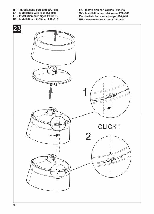
ES - Instalación con varillas 290÷915SV - Installation med stängerna 290÷915DA - Installation med stænger 290÷915RU - Установка на штанги 290÷915
33
24 25
26
12
3!! !!
35
34
27
L2L1N1
PE
MO
TOR
MO
TOR
E
MP
PE
N1
L1
MN
L2
COLLEGAREALL’ASTA
Light (optional)Luce (opzionale)
MP
MN
TO ROD
nero-black
rosso-red
nero-black
rosso-red
nero-blacknero-black
marrone-brow
n
marrone-brow
n
blu-blue
blu-blue
giallo/verde-yellow/green
giallo/verde-yellow
/green
28

35
29
1 2
30

36
31
Andare a fig.44Go to fig. 44Aller à la fig.44Gehe zu Abb.44Ve a la figura.44Gå till fig.44Gå til fig.44Перейдите к рис.44
37
32
33
IT - Installazione con asta 160EN - Installation with rod 160FR - Installation avec tige 160DE - Installation mit Stab 160
ES - Instalación con varilla 160SV - Installation med stång 160DA - Installation med stang 160RU - Установка на штанги штангу 160
38
34
1
2 3
39
36
L2L1N1
PE
MO
TOR
MO
TOR
E
MP
PE
N1
L1
MN
L2
COLLEGAREALL’ASTA
Light (optional)Luce (opzionale)
MP
MN
TO ROD
nero-black
rosso-red
nero-black
rosso-red
nero-blacknero-black
marrone-brow
n
marrone-brow
n
blu-blue
blu-blue
giallo/verde-yellow/green
giallo/verde-yellow
/green
35
1
2
3
4
!! !!35
40
37
38
1
23
41
39
1
2
40

42
41
42
1
2

43
43
CLICK !!
1
2

44
45
90°
44
1
2

45
46
47
1
2

46
49
48

47
50
48
51
MIN VENT
MAX VENT MIN REVERSE
MAX REVERSE
OFF
52 HYSTERESIS ZONE

49
53 54
55
56
50
57 POTENTIOMETER
PE
IGND+OUTUs
POT (10kOhm)
D1
1x0.35mmq
0V 10 A1
INTERRUTTORE LUCE
6x0.35mmq
D2 GND
1
3
N L
~230VMains
3x0.75mmq
4
1 Potentiometer 10kOhm with dry contact
2 Switch for light (optional), 250V-3A
3 Potentiometer terminal block from product
4 Power terminal block from product
BU=blue bluBN=brown marroneGNYE=yellow/green giallo/verde
Wires color code(BU) (BN) (GNYE)
2
Colore cavi
POTENZIOMETRO
LIGHT SWITCH
Potenziometro da 10kOhm con contatto privo di potenziale
Interruttore per luce (opzionale), 250V-3A
Morsettiera potenziometro (dal prodotto)
Morsettiera alimentazione (dal prodotto)
58
BOX
(BN)
(BU)
(GNYE)
BU=blue bluBN=brown marroneGNYE=yellow/green giallo/verde
RD=red YE=yellow rosso giallo
BK=black GN=green PK=pink nero verde rosa
Wires color code
D1
0V
10
A1
D2
GND
3
4
L
N
PE
Colori cavi
3 Potentiometer terminal block from product
4 Power terminal block from product
Morsettiera potenziometro (dal prodotto)
Morsettiera alimentazione (dal prodotto)
(WH)
(BN)
(GN)
(YE)
(GY)
(PK)
WH =white GY=grey bianco grigio
TO WIFI BOARD TO IR BOARDALLA SCHEDA WIFI ALLA SCHEDA TELECOMANDO
L2
L1
N1
PE
MOTORMOTORE
(GNYE)
(BU)
(BN)
(BK)
(RD)
(GNYE)
(BU)
(BN)
(BK)
MP
PE
N1
L1
MN
L2
CO
LLE
GA
RE
ALL
’AS
TA
(GNYE)
(BU)
(BN)
(BK)
Light (optional)Luce (opzionale)
(BK)
(RD)MP
MN(BK)
(RD)
TO R
OD
51
IT - Smontaggio coppe (asta 290÷915)EN - Dismantling caps (rods 290÷915)FR - Démontage carters (tiges 290÷915)DE - Ausbauen der Kappen (Stäben 290÷915)
ES - Desmontaje de copas (varillas 290÷915)SV - Montera ner kupa (stängerna 290÷915)DA - Afmontering af kupler (stænger 290÷915)RU - Демонтаж колпаков (штанги 290÷915)
59
60

52
61
62

53
63
64
IT - Smontaggio coppe (asta 160)EN - Dismantling caps (rods 160)FR - Démontage carters (tiges 160)DE - Ausbauen der Kappen (Stäben 160)
ES - Desmontaje de copas (varillas 160)SV - Montera ner kupa (stängerna 160)DA - Afmontering af kupler (stænger 160)RU - Демонтаж колпаков (штанги 160)

54
65

55
66
67

56
68
VORTICE LIMITEDBeeches House - Eastern AvenueBurton on TrentDE13 0BBTel. +44 1283-492949UNITED [email protected]
VORTICE ELETTROSOCIALI S.p.A.Strada Cerca, 2 - frazione di Zoate20067 TRIBIANO (MI)Tel. +39 [email protected]
VORTICE LATAM S.A.3er Piso, O cina 9-B, Edi cioMeridianoGuachipelín, Escazú, San JoséPO Box 10-1251 Tel +506 2201 6242; COSTA [email protected]
VORTICE VENTILATION SYSTEM (CHANGZHOU) CO., LTDBuilding 19 , No.388 West Huanghe Road, Xinbei District,Changzhou, Jiangsu Province CAP:[email protected]
Vortice Elettrosociali S.p.A. si riserva il diritto di apportare tutte le varianti migliorative ai prodotti in corso di vendita.Vortice Elettrosociali S.p.A. reserves the right to make improvements to products at any time and without prior notice.La société Vortice Elettrosociali S.p.A. se réserve le droit d'apporter toutes les variations afin d'améliorer ses produits en cours de commercialisation.Die Firma Vortice Elettrosociali S.p.A. behält sich vor, alle eventuellen Verbesserungsänderungen an den Produkten des Verkaufsangebots vorzunehmen.Vortice Elettrosociali S.p.A. se reserva el derecho de incorporar todas las mejoras necesarias a los productos en fase de venta.Vortice Elettrosociali S.p.A.

57
A TAGLIANDO INTERVENTO IN GARANZIACERTIFICATE OF WORK PERFORMED UNDER GUARANTEECOUPON INTERVENTION SOUS GARANTIE
DATA INTERVENTODATE OF WORK - DATE INTERVENTION
TIMBRO CENTRO ASSISTENZA
TAGLIANDO INTERVENTO IN GARANZIACERTIFICATE OF WORK PERFORMED UNDER GUARANTEECOUPON INTERVENTION SOUS GARANTIE
DATA INTERVENTODATE OF WORK - DATE INTERVENTION
TIMBRO CENTRO ASSISTENZASTAMP OF TECHNICAL ASSISTANCE CENTRE - CACHET SERVICE APRES-VENTE
TAGLIANDO INTERVENTO IN GARANZIACERTIFICATE OF WORK PERFORMED UNDER GUARANTEECOUPON INTERVENTION SOUS GARANTIE
DATA INTERVENTODATE OF WORK - DATE INTERVENTION
TIMBRO CENTRO ASSISTENZA
TAGLIANDO INTERVENTO IN GARANZIACERTIFICATE OF WORK PERFORMED UNDER GUARANTEECOUPON INTERVENTION SOUS GARANTIE
DATA INTERVENTODATE OF WORK - DATE INTERVENTION
TIMBRO CENTRO ASSISTENZA
B
C
D
STAMP OF TECHNICAL ASSISTANCE CENTRE - CACHET SERVICE APRES-VENTE
STAMP OF TECHNICAL ASSISTANCE CENTRE - CACHET SERVICE APRES-VENTE
STAMP OF TECHNICAL ASSISTANCE CENTRE - CACHET SERVICE APRES-VENTE
ITALIACONDIZIONI DI GARANZIA
VORTICE ELETTROSOCIALI SPA garantisce i suoiprodotti per 2 anni dalla data dell’acquisto, che deveessere comprovata da idoneo documento fiscale (scontrinoo fattura), rilasciato dal venditore. Nel suddetto periodo digaranzia VORTICE ELETTROSOCIALI SPA si impegna,dopo aver effettuato le opportune valutazioni tecniche, ariparare o a sostituire gratuitamente le partidell’apparecchio che risultassero affette da difetti difabbricazione. La presente garanzia, da attivare nei modie nei termini di seguito indicati, lascia impregiudicati idiritti derivanti al consumatore dalla applicazione del D.lgs. 24/2002.Tali diritti, conformemente alla legge,potranno essere fatti valere esclusivamente nei confrontidel proprio venditore. La presente garanzia è valida su tutto il territorio italiano.Modalità e condizioni di attivazione della garanziaGli interventi in garanzia (riparazioni o sostituzioni delprodotto ovvero delle parti difettose) saranno eseguitipresso uno dei Centri di Assistenza Tecnica autorizzati daVORTICE ELETTROSOCIALI SPA, il cui indirizzo èdisponibile sull’elenco telefonico alfabetico o contattandoil numero verde 800.555.777.La prestazione eseguita in garanzia non prolunga ilperiodo della garanzia. Pertanto, incaso di sostituzionedel prodotto o di un suo componente, sul bene o sulsingolo componente fornito in sostituzione non decorreun nuovo periodo di garanzia ma si deve tener contodella data di acquisto del prodotto originario.
UK AND IRELANDCONDITIONS OF WARRANTY
This guarantee is offered as an extra benefit anddoes not affect your legal rights. All electricalappliances produced byVORTICE ELETTROSOCIALI SPA are guaranteed bythe Company for 2 years against faulty material orworkmanship. If any part is found to be defective in thisway within the first twentyfour months from the date ofpurchase or hire purchase agreement, we, or ourauthorised service agents, will replace or at our optionrepair that part without any charge for materials or labouror transportation, provided that the appliance has beenused only in accordance with the instructions providedwith each appliance and has been not connected to anunsuitable electricity supply, or subjected to misuse,neglect or damage or modified or repaired by any personnot authorised by us. The correct electricity supplyvoltage is shown on the rating plate attached to theappliance. This guarantee is normally available only tothe original purchaser of theappliance, but the Companywill consider written applications for transfer. Should anydefect arise in any Vortice product and a claim underguarantee become necessary, the appliance should becarefully packed and returned to your approved Vorticestockist. This portion of the guarantee should be attachedto the appliance.
ITALIASpedire la garanzia in bustachiusa a:Vortice Elettrosociali S.p.A.Strada Cerca 2Frazione di Zoate20067 Tribiano Milano.
UK-IRELANDSend the guaranteein sealed envelope to:Vortice LimitedBeeches HouseEastern AvenueBurton on TrentDE13 0BB United Kingdom
OTHER COUNTRIESPlease send the guarantee to theretailer’s address in the country wherethe appliance has been purchased.
Autorizzo VORTICE ELETTROSOCIALI SPAad inserire i miei dati nelle sueliste e a comunicarli a terzi perl’invio di materiale pubblicitarioed informativo. In ogni momento,a norma dell’art. 13 legge675/96, potrò avere accesso aimiei dati, chiederne la modificao la cancellazione oppureoppormi al loro utilizzo scrivendoa:Vortice Elettrosociali S.p.A.Responsabiletrattamento dati - Strada Cerca, 2 - Frazione di Zoate -20067 Tribiano (MI).
I authorize VORTICE LTD. to include my personaldetails within theirdatabase, which they use,via a third party for thedespatch of advertisingmaterial, at any time, inaccordance with theregulations in force withinmy country. I can haveaccess to my details andcan request changes, orprohibit the usage of mydetails.This will be doneby addressing my requestdirectly to:Vortice LimitedBeeches HouseEastern AvenueBurton on TrentDE13 0BB UnitedKingdom.
I authorize VORTICE ELETTROSOCIALI SPAand its local distributors toinclude my personal detailswithin their database and theycan use it through a third partyfor the despatch of advertisingmaterial. At any time, inaccordance with the regulationsin force within my country. I canhave access to details and canask to make changes, orprohibit the usage of mydetails.This will be done byaddressing my request directlyto the headquarters of the localdistributor where the appliancehas been bought.
I do not authorize(please tick if required)
Non autorizzo(barrare se interessa)
I do not authorize(please tick if required)

ANNI
YEARS2
1 GARANZIA - GUARANTEE - GARANTIE
DA CONSERVARETO BE RETAINEDA CONSERVER
Per poter usufruire della garanzia il cliente deve compilare e rispedire a VORTICE ELETTROSOCIALI SPA, entro 8 giorni dall’acquisto, la “Parte2” del tagliando di garanzia, all’indirizzo e con le modalità in tale parte riportate.La “Parte 1” del tagliando di garanzia deve essere conservata e presentata,unitamente al documento fiscale (scontrino o fattura) rilasciato dal venditore al momento dell’acquisto, al Centro di Assistenza autorizzato di VORTICE ELETTROSOCIALI SPA, che dovrà eseguire l’intervento in garanzia.
This warranty must be attached to the appliance should it need to be returned for servicing.N.B. Guarantee is only valid if all details are completed correctly.
ATTENTION: pour bénéficier de la garantie, le présent certificat doit obligatoirement accompagner l’appareil présumé défectueux. Le certificatdoit porter le cachet du revendeur et la date d’achat.A defaut, la garantie sera comptée à partir de la date de sortie d’usine.
EsclusioniLa presente garanzia non copre:•Le rotture provocate dal trasporto.• I difetti o guasti derivanti da uso non corretto o improprio da parte del cliente.• I difetti derivanti dal mancato rispetto delle avvertenze e condizioni d’uso indicate nel libretto di istruzioni ed uso allegato al prodotto.• I difetti derivanti da non corretta installazione ovvero da una installazione effettuata senza rispettare quanto previstonel relativo capitolo del libretto di istruzioni ed uso.• I guasti derivanti da un errato allacciamento alla rete di alimentazione elettrica o per tensione di alimentazione diversa da quella prevista per l’apparecchio, ovvero diversa dal limite stabilito dalle norme CEI (+/- 10% del valorenominale).La presente garanzia non copre, inoltre, gli eventuali difetti derivanti da una cattiva manutenzione ovvero da interventi effettuati da personale non qualificato o da terzi non autorizzati.
TIMBRO RIVENDITOREstamp of supplier
cacher du vendeurDATA SPEDIZIONE
Mailing date - Date d’expédition
DATA ACQUISTOPurchase date - Date d’achat
CONF.
COLL.
DATI UTENTE / CUSTOMER DATA / COORDONNÉES DE L’UTILISATEURnome / name / nom _____________________________________________________cognome / surname / prenom _____________________________________________via / street / rue ________________________________________________________cap / post code / code postal ______________________________________________città / town ____________________________________________________________
Dichiaro di aver preso atto delle condizioni di garanzia specificate sul certificato in mio possesso e autorizzo la gestione dei miei dati personali (v.retro).I have read and understood the terms and conditions of this guarantee and I authorize the processing of my personal details (see overleaf).Suivant les conditions de garantie définies par le certificat en ma possession j’autorise l’utilisation de mes coordonnées (voir au verso).
Firma / Signature / Signature ______________________________________________
2 GARANZIA - GUARANTEE - GARANTIE
DA SPEDIRE (entro 8 giorni dall’acquisto)
TO SEND (within 8 days from date of purchase)A RETOURNER (dans les 8 jours après l’achat)
TIMBRO RIVENDITOREstamp of supplier
cacher du vendeur
ANNI
YEARS2
DATA ACQUISTOPurchase date - Date d’achat
DATA SPEDIZIONEMailing date - Date d’expédition