ИНСТРУКЦИЯ ПО УСТАНОВКЕ INSTALLATIONSANVSNING AIR...
29
ENGLISH FRANÇAIS DEUTSCH ITALIANO ESPAÑOL ΕΛΛΗΝΙΚΑ PORTUGUÊS SVENSKA РУССКИЙ ЯЗЫК AIR CONDITIONER (SPLIT TYPE) INSTALLATION MANUAL MANUEL D’INSTALLATION INSTALLATIONS-HANDBUCH MANUALE DI INSTALLAZIONE MANUAL DE INSTALACIÓN ΕΓΧΕΙΡΙ∆ΙΟ ΕΓΚΑΤΑΣΤΑΣΗΣ MANUAL DE INSTALAÇÃO ИНСТРУКЦИЯ ПО УСТАНОВКЕ INSTALLATIONSANVSNING Not accessible to the general public CLIMATISEUR (TYPE SEPARE) Vente interdite au grand public KLIMAGERÄT (SPLIT-TYP) Kein öffentlicher Zugang CONDIZIONATORE D’ARIA (TIPO SPLIT) Non accessibile a clienti generici AIRE ACONDICIONADO (TIPO SPLIT) No destinado al público en general ΚΛΙΜΑΤΙΣΤΙΚΟ (∆ΙΑΙΡΟΥΜΕΝΟΥ ΤΥΠΟΥ) Μη προσβάσιο από το γενικό κοινό AR CONDICIONADO (TIPO SPLIT) Não acessível ao público em geral КОНДИЦИОНЕР (РАЗДЕЛИТЕЛЬНЫЙ ТИП) Ограничено для доступа широкой общественности LUFTKONDITIONERINGSAPPARAT (SPLITTYP) Inte tillgänglig för allmänheten 4-Way Air Discharge Cassette Type Type cassette à 4 voies de soufflage 4-Wege-Belüftungskassette Tipo a cassetta con scarico d'aria a 4 vie Modelo de casete de distribución de aire de 4 vías Εκροή αέρα 4-∆ιευθύνσεων Τύπου Κασέτας Descarga de ar tipo cassete de 4 vias 4-направленная кассета выписка воздуха Apparat med 4-vägars luftutsläpp Indoor Unit/Unité intérieure/Raumeinheit/Unità interna/Unidad interior Εσωτερική ονάδα/Unidade interior/Внутренний блок/Inomhusenhet Heat Pump Model Modèle à thermopompe Geräte mit Heizung Modello con pompa di riscaldamento Modelo con bomba de calor Μοντέλο ε Αντλία Θερότητας Modelo de bomba térmica Модель теплового насоса Värmepumpsmodell Cooling Only Model Modèle à froid seul Geräte nur zur Kühlung Modello solo per raffreddamento Modelo de refrigeración únicamente Μοντέλο Ψύξης αποκλειστικά Modelo Apenas para Refrigeração Модель только c охлаждением Modell endast för avkylning RAS-M10SMUV-E RAS-M13SMUV-E RAS-M16SMUV-E RAS-M10SMUCV-E RAS-M13SMUCV-E RAS-M16SMUCV-E Ceiling panel/Panneau pour plafond/Deckenrahmen/Pannello al soffitto/ Panel de techo/Φάτνωµα ρφής/Painel de tecto/Потолочная панель/ Takpanel RB-B11MC(W)E
Transcript of ИНСТРУКЦИЯ ПО УСТАНОВКЕ INSTALLATIONSANVSNING AIR...
EN
GL
ISH
FR
AN
ÇA
ISD
EU
TS
CH
ITA
LIA
NO
ES
PAÑ
OL
ΕΛΛΗΝΙΚΑ
PO
RT
UG
UÊ
SS
VE
NS
KA
РУ
СС
КИ
Й Я
ЗЫ
К
AIR CONDITIONER (SPLIT TYPE)
INSTALLATION MANUALMANUEL D’INSTALLATIONINSTALLATIONS-HANDBUCHMANUALE DI INSTALLAZIONEMANUAL DE INSTALACIÓNΕΓΧΕΙΡΙ∆ΙΟ ΕΓΚΑΤΑΣΤΑΣΗΣMANUAL DE INSTALAÇÃOИНСТРУКЦИЯ ПО УСТАНОВКЕINSTALLATIONSANVSNING
Not accessible to the general publicCLIMATISEUR (TYPE SEPARE) Vente interdite au grand public KLIMAGERÄT (SPLIT-TYP) Kein öffentlicher Zugang CONDIZIONATORE D’ARIA (TIPO SPLIT) Non accessibile a clienti genericiAIRE ACONDICIONADO (TIPO SPLIT) No destinado al público en generalΚΛΙΜΑΤΙΣΤΙΚΟ (∆ΙΑΙΡΟΥΜΕΝΟΥ ΤΥΠΟΥ) Μη προσβάσιµο από το γενικό κοινόAR CONDICIONADO (TIPO SPLIT) Não acessível ao público em geralКОНДИЦИОНЕР (РАЗДЕЛИТЕЛЬНЫЙ ТИП) Ограничено для доступа широкой
общественностиLUFTKONDITIONERINGSAPPARAT (SPLITTYP) Inte tillgänglig för allmänheten
4-Way Air Discharge Cassette TypeType cassette à 4 voies de soufflage4-Wege-BelüftungskassetteTipo a cassetta con scarico d'aria a 4 vieModelo de casete de distribución de aire de 4 víasΕκροή αέρα 4-∆ιευθύνσεων Τύπου ΚασέταςDescarga de ar tipo cassete de 4 vias4-направленная кассета выписка воздухаApparat med 4-vägars luftutsläpp
Indoor Unit/Unité intérieure/Raumeinheit/Unità interna/Unidad interiorΕσωτερική µονάδα/Unidade interior/Внутренний блок/Inomhusenhet
Heat Pump Model Modèle à thermopompe Geräte mit HeizungModello con pompa di riscaldamento Modelo con bomba de calorΜοντέλο µε Αντλία ΘερµότηταςModelo de bomba térmicaМодель теплового насосаVärmepumpsmodell
Cooling Only ModelModèle à froid seulGeräte nur zur KühlungModello solo per raffreddamentoModelo de refrigeración únicamenteΜοντέλο Ψύξης αποκλειστικάModelo Apenas para RefrigeraçãoМодель только c охлаждениемModell endast för avkylning
RAS-M10SMUV-ERAS-M13SMUV-ERAS-M16SMUV-E
RAS-M10SMUCV-ERAS-M13SMUCV-ERAS-M16SMUCV-E
Ceiling panel/Panneau pour plafond/Deckenrahmen/Pannello al soffitto/Panel de techo/Φάτνωµα ρφής/Painel de tecto/Потолочная панель/Takpanel
RB-B11MC(W)E
1 SAFETY PRECAUTIONS.......................................................... 12 ACCESSORY PARTS AND PARTS TO BE PROCURED
LOCALLY .................................................................................. 33 SELECTION OF INSTALLATION PLACE................................. 44 INSTALLATION OF INDOOR UNIT .......................................... 65 DRAIN PIPING WORK............................................................ 116 REFRIGERANT PIPING AND EVACUATING......................... 157 EVACUATING ......................................................................... 178 ELECTRICAL WORK .............................................................. 189 APPLICABLE CONTROLS...................................................... 2110 TEST OPERATION ................................................................. 2311 INSTALLATION/SERVICING TOOLS..................................... 2312 MAINTENANCE ...................................................................... 24
Please read this Installation Manual carefully before installing the Air Conditioner.• This Manual describes the installation method of the indoor unit.• For installation of the outdoor unit, follow the Installation Manual
attached to the outdoor unit.
This Air Conditioner is a new type which adopts the new refrigerant HFC (R410A) instead of the conventional refrigerant R22. R410A is an ozone friendly refrigerant.
1 MESURES DE SECURITE........................................................ 12 PIÈCES ACCESSOIRES ET PIÈCES NON FOURNIES .......... 33 SELECTION DU LIEU D’INSTALLATION ................................. 44 INSTALLATION DE L’UNITE INTERIEURE.............................. 65 INSTALLATION DES TUYAUX D’EVACUATION ................... 116 TUYAUTERIE DE FRIGORIGÈNE ET ÉVACUATION............ 157 EVACUATION DE L’AIR ......................................................... 178 INSTALLATION ELECTRIQUE............................................... 189 COMMANDES APPLICABLES ............................................... 2110 ESSAI DE FONCTIONNEMENT............................................. 2311 OUTILS D’INSTALLATION/D’ENTRETIEN............................. 2312 ENTRETIEN ............................................................................ 24
Veuillez lire attentivement ce Manuel d'installation avant d'installer le climatiseur.• Ce manuel décrit la procédure d'installation de l'unité intérieure.• Pour installer l'unité extérieure, reportez-vous au Manuel
d'installation fourni avec l'unité extérieure.
Ce nouveau type de climatiseur utilise le nouveau réfrigérant HFC (R410A) au lieu du traditionnel R22. Le R410A est un réfrigérant qui respecte la couche d'ozone.
1 SICHERHEITSVORKEHRUNGEN............................................ 12 ZUBEHÖR UND BAUSEITS BEREITZUSTELLENDE TEILE... 33 AUSWAHL DES AUFSTELLUNGSORTES .............................. 44 INSTALLATION DER RAUMEINHEIT....................................... 65 INSTALLATION DES KONDENSWASSER-ABLAUFS........... 116 KÜHLMITTELLEITUNGSSYSTEM UND ENTLÜFTUNG ....... 157 ENTLÜFTEN DER ROHRLEITUNGEN................................... 178 ELEKTROINSTALLATION ...................................................... 189 STEUERUNGSMÖGLICHKEITEN.......................................... 2110 TESTLAUF .............................................................................. 2311 INSTALLATIONS / WARTUNGSWERKZEUGE ..................... 2312 WARTUNG.............................................................................. 24
Bitte lesen Sie dieses Handbuch sorgfältig, bevor Sie mit der Installation des Klimagerätes beginnen.• In diesem Handbuch wird die Installation der Inneneinheit
beschrieben.• Um die Außeneinheit zu installieren, folgen Sie den Anweisungen
des Handbuchs, das der Außeneinheit beiliegt.
Dies ist ein neuartiges Klimagerät. Anstatt des herkömmlichen Kältemittels R22 verwendet es das neue HFC Kältemittel R410A. R410A schont die Ozonschicht.
1 PRECAUZIONI PER LA SICUREZZA....................................... 12 ACCESSORI E PARTI DA ACQUISTARE SUL POSTO .......... 33 SCELTA DEL POSTO D’INSTALLAZIONE............................... 44 INSTALLAZIONE DELL’UNITÀ INTERNA ................................ 65 LAVORO PER TUBAZIONE DI SCARICO.............................. 116 TUBAZIONI DEL REFRIGERANTE E SCARICO ................... 157 SPURGO................................................................................. 178 ESECUZIONE DEI COLLEGAMENTI ELETTRICI.................. 189 COMANDI UTILIZZABILI......................................................... 2110 FUNZIONAMENTO DI PROVA............................................... 2311 ATTREZZI PER L’INSTALLAZIONE/PER LA
MANUTENZIONE.................................................................... 2312 MANUTENZIONE.................................................................... 24
Prima di eseguire l'installazione del condizionatore d'aria, leggere attentamente il Manuale d'installazione.• Questo manaule il metodo d'installazione dell'unità interna.• Per l'installazione dell'unità esterna, fare riferimento al Manuale
d'installazione fornito con l'unità esterna.
Questo condizionatore d'aria è di dipo nuovo e impiega il nuovo refrigerante HFC (R410A) invece del R22, tradizionalmente usato. R410A è un refrigerante ecologicamente rispettoso dello strato d'ozono.
CONTENTS/SOMMAIRE/INHALT/INDICE
ENGLISH
ADOPTION OF NEW REFRIGERANT
FRANÇAIS
UTILISATION DU NOUVEAU REFRIGERANT
DEUTSCH
EINFÜHRUNG EINES NEUEN KÜHLMITTELS
ITALIANO
ADOZIONE DI UN NUOVO REFRIGERANTE
i
EN
GL
ISH
FR
AN
ÇA
ISD
EU
TS
CH
ITA
LIA
NO
ES
PAÑ
OL
ΕΛΛΗΝΙΚΑ
PO
RT
UG
UÊ
SS
KA
РУ
СС
КИ
Й Я
ЗЫ
К
1 PRECAUCIONES SOBRE SEGURIDAD.................................. 12 COMPONENTES ACCESORIOS Y COMPONENTES DE
SUMINISTRO LOCAL ............................................................... 33 SELECCIÓN DEL LUGAR DE INSTALACIÓN ......................... 44 INSTALACIÓN DE LA UNIDAD INTERIOR .............................. 65 CANALIZACIÓN DE DRENAJE .............................................. 116 TUBOS DE REFRIGERANTE Y EVACUACIÓN..................... 157 EVACUACIÓN......................................................................... 178 TRABAJOS EN EL SISTEMA ELÉCTRICO............................ 189 CONTROLES APLICABLES ................................................... 2110 FUNCIONAMIENTO DE PRUEBA .......................................... 2311 HERRAMIENTAS DE INSTALACIÓN/REPARACIÓN ............ 2312 MANTENIMIENTO .................................................................. 24
Lea atentamente este Manual de instalación antes de proceder a la instalación del aparato de aire acondicionado.• Este manual describe el método de instalación de la unidad interior.• Para la instalación de la unidad exterior, consulte el Manual de
instalación que acompaña a la unidad exterior.
Este acondicionador de aire es un tipo Nuevo que adopta el refrigerante nuevo HFC (R410A) en vez del refrigerante convencional R22. El R410A es un refrigerante que no daña la capa de ozono.
1 ΠΡΟΦΥΛΑΞΕΙΣ ΑΣΦΑΛΕΙΑΣ ................................................... 12 ΠΑΡΕΛΚΌΜΕΝΑ ΑΝΤΑΛΛΑΚΤΙΚΆ ΚΑΙ ΕΞΑΡΤΉΜΑΤΑ ΑΠΌ ΤΗΝ ΤΟΠΙΚΉ ΑΓΟΡΆ ............................................................... 3
3 ΕΠΙΛΟΓΗ ΤΟΥ ΧΩΡΟΥ ΕΓΚΑΤΑΣΤΑΣΗΣ ................................ 44 ΕΓΚΑΤΑΣΤΑΣΗ ΤΗΣ ΕΣΩΤΕΡΙΚΗΣ ΜΟΝΑ∆ΑΣ....................... 65 ΕΓΚΑΤΑΣΤΑΣΗ ΣΩΛΗΝΩΣΕΩΝ ΑΠΟΣΤΡΑΓΓΙΣΗΣ ............... 116 ΣΩΛΗΝΩΣΕΙΣ ΨΥΞΗΣ ΚΑΙ ΑΠΟΣΤΡΑΓΓΙΣΗΣ ....................... 157 ΕΚΚΕΝΩΣΗ ............................................................................. 178 ΗΛΕΚΤΡΟΛΟΓΙΚΑ .................................................................. 189 ΕΦΑΡΜΟΣΙΜΟΙ ΕΛΕΓΧΟΙ ...................................................... 2110 ∆ΟΚΙΜΑΣΤΙΚΗ ΛΕΙΤΟΥΡΓΙΑ .................................................. 2311 ΕΡΓΑΛΕΙΑ ΕΓΚΑΤΑΣΤΑΣΗΣ/ ΕΠΙΣΚΕΥΗΣ ............................ 2312 ΣΥΝΤΗΡΗΣΗ........................................................................... 24
Παρακαλώ διαβάστε προσεχτικά το Εγχειρίδιο Εγκατάστασης πριν από την εγκατάσταση του Κλιµατιστικού. Το παρόν Εγχειρίδιο περιγράφει τη µέθοδο εγκατάστασης της εσωτερικής µονάδας.
Για την εγκατάσταση της εξωτερικής µονάδας, συµβουλευτείτε το Εγχειρίδιο Εγκατάστασης που συνοδεύει την εξωτερική µονάδα.
Το παρόν Κλιµατιστικό είναι νέου τύπου και υιοθετεί το νέο ψυκτικό HFC (R410A) αντί για το συµβατικό ψυκτικό R22. Το R410A είναι ένα ψυκτικό φιλικό ως προς το όζον.
1 PRECAUÇÕES DE SEGURANÇA............................................ 12 ACESSÓRIOS E PEÇAS ADQUIRIDAS LOCALMENTE ......... 33 SELECÇÃO DO LOCAL DE INSTALAÇÃO.............................. 44 INSTALAÇÃO DA UNIDADE INTERIOR .................................. 65 INSTALAÇÃO DA TUBAGEM DE DRENAGEM ..................... 116 TUBAGEM DE REFRIGERANTE E EVACUAÇÃO................. 157 EXPURGO............................................................................... 178 LIGAÇÕES ELÉCTRICAS....................................................... 189 CONTROLOS APLICÁVEIS.................................................... 2110 OPERAÇÃO DE TESTE.......................................................... 2311 FERRAMENTAS DE INSTALAÇÃO/REPARO ....................... 2312 MANUTENÇÃO....................................................................... 24
Leia atentamente o presente Manual de Instalação antes de instalar o Ar Condicionado.• O presente manual descreve o método de instalar a unidade
interior.• Para a instalação de uma unidade exterior, siga o Manual de
Instalação que acompanha a unidade exterior.
O presente aparelho de ar condicionado é um novo tipo que adopta o novo refrigerante HFC (R410A) em vez do refrigerante convencional R22. O R410A é um refrigerante que não prejudica o ozono.
1 МЕРЫ ПРЕДОСТОРОЖНОСТИ............................................. 12 ДОПОЛНИТЕЛЬНЫЕ ПРИНАДЛЕЖНОСТИ И
КОМПОНЕНТЫ, ПРИОБРЕТАЕМЫЕ НА МЕСТЕ ................. 33 ВЫБОР МЕСТА УСТАНОВКИ ................................................ 44 УСТАНОВКА ВНУТРЕННЕГО БЛОКА ................................... 65 РАБОТЫ HA ДРЕНАЖНОМ ТРУБОПРОВОДЕ................... 116 ПОДАЧА И ОТКАЧКА XЛAДAГEHTA.................................... 157 ОТКАЧКА................................................................................ 178 ЭЛЕКТРОМОНТАЖНЫЕ РАБОТЫ ...................................... 189 ПРИМЕНИМЫЕ СРЕДСТВА УПРАВЛЕНИЯ........................ 2110 ТЕСТОВАЯ РАБОТА ............................................................. 2311 УСТАНОВКА/ИНСТРУМЕНТЫ ДЛЯ ОБСЛУЖИВАНИЯ..... 2312 ТЕХНИЧЕСКОЕ ОБСЛУЖИВАНИЕ ..................................... 24
Внимательно прочитайте данное Руководство перед установкой кондиционера.• B данном Руководстве описывается метод установки
внутреннего блока.• Для установки наружного блока следуйте инструкциям
Руководства по установке, прилагаемого к наружному блоку.
Данный кондиционер является кондиционером нового типа. в котором предусмотрено использование нового хладагента НЕС (R410A) вместо традиционного R22. R410A - хладагент, не разрушающий озоновый слой.
ÍNDICE/ΠΕΡΙΕΧΟΜΕΝΑ/ÍNDICE/СОДЕРЖАНИЕ
ESPAÑOL
ADOPCIÓN DE NUEVO REFRIGERANTE
ΕΛΛΗΝΙΚA
ΥΙΟΘΕΤΗΣΗ ΝΕΟΥ ΨΥΚΤΙΚΟΥ
PORTUGUÊS
ADOPCIÓN DE NUEVO REFRIGERANTE
РУССКИЙ ЯЗЫК
ВНЕДРЕНИЕ НОВОГО ХЛАДАГЕНТА
ii
SV
EN
1 SÄKERHETSFÖRESKRIFTER................................................. 12 TILLBEHÖR OCH DELAR SOM ANFÖRSKAFFAS LOKALT... 33 VAL AV INSTALLATIONSPLATS.............................................. 44 INOMHUSENHETENS INSTALLATION ................................... 65 ARBETE MED TÖMNINGSRÖREN........................................ 116 KYLVÄTSKANS RÖRLEDNING OCH TÖMNING................... 157 TÖMNING................................................................................ 178 ELEKTRISKT ARBETE ........................................................... 189 TILLÄMPBARA KONTROLLER .............................................. 2110 TESTFUNKTION..................................................................... 2311 INSTALLATION / SERVICEVERKTYG................................... 2312 UNDERHÅLL........................................................................... 24
Vänligen läs denna Installationshandbok noga innan du installerar luftkonditioneringsapparaten.• Denna handbok beskriver hur inomhusenheten ska installeras.• För installation av utomhusenheten, följ Installationshandboken
som är ansluten till utomhusenheten.
Denna luftkonditioneringsapparat är en ny typ som använder den nya kylvätskan HFC (R410A) i stället för den vanliga kylvätskan R22. R410A är en kylvätska som inte är skadlig för ozonskiktet.
INNEHÅLL
SVENSKA
ANVÄNDANDE AV NY KYLVÄTSKA
iii
EN
GL
ISH
FR
AN
ÇA
ISD
EU
TS
CH
ITA
LIA
NO
ES
PAÑ
OL
ΕΛΛΗΝΙΚΗ
PO
RT
UG
UÊ
S##
#SW
###
U##
#
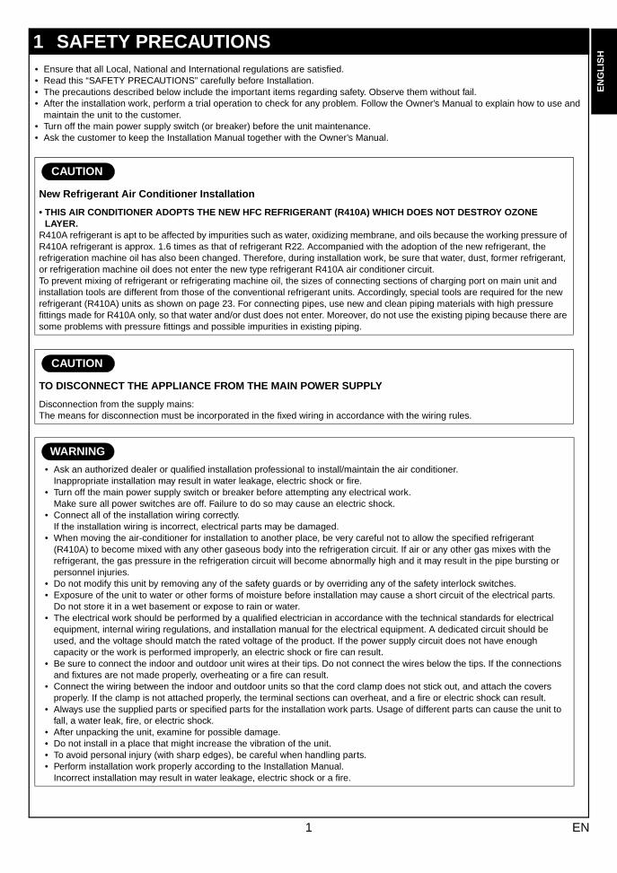
• Ensure that all Local, National and International regulations are satisfied.• Read this “SAFETY PRECAUTIONS” carefully before Installation.• The precautions described below include the important items regarding safety. Observe them without fail.• After the installation work, perform a trial operation to check for any problem. Follow the Owner’s Manual to explain how to use and
maintain the unit to the customer.• Turn off the main power supply switch (or breaker) before the unit maintenance.• Ask the customer to keep the Installation Manual together with the Owner’s Manual.
1 SAFETY PRECAUTIONS
CAUTION
New Refrigerant Air Conditioner Installation
• THIS AIR CONDITIONER ADOPTS THE NEW HFC REFRIGERANT (R410A) WHICH DOES NOT DESTROY OZONE LAYER.
R410A refrigerant is apt to be affected by impurities such as water, oxidizing membrane, and oils because the working pressure of R410A refrigerant is approx. 1.6 times as that of refrigerant R22. Accompanied with the adoption of the new refrigerant, the refrigeration machine oil has also been changed. Therefore, during installation work, be sure that water, dust, former refrigerant, or refrigeration machine oil does not enter the new type refrigerant R410A air conditioner circuit.To prevent mixing of refrigerant or refrigerating machine oil, the sizes of connecting sections of charging port on main unit and installation tools are different from those of the conventional refrigerant units. Accordingly, special tools are required for the new refrigerant (R410A) units as shown on page 23. For connecting pipes, use new and clean piping materials with high pressure fittings made for R410A only, so that water and/or dust does not enter. Moreover, do not use the existing piping because there are some problems with pressure fittings and possible impurities in existing piping.
CAUTION
TO DISCONNECT THE APPLIANCE FROM THE MAIN POWER SUPPLY
Disconnection from the supply mains:The means for disconnection must be incorporated in the fixed wiring in accordance with the wiring rules.
WARNING
• Ask an authorized dealer or qualified installation professional to install/maintain the air conditioner.Inappropriate installation may result in water leakage, electric shock or fire.
• Turn off the main power supply switch or breaker before attempting any electrical work.Make sure all power switches are off. Failure to do so may cause an electric shock.
• Connect all of the installation wiring correctly.If the installation wiring is incorrect, electrical parts may be damaged.
• When moving the air-conditioner for installation to another place, be very careful not to allow the specified refrigerant (R410A) to become mixed with any other gaseous body into the refrigeration circuit. If air or any other gas mixes with the refrigerant, the gas pressure in the refrigeration circuit will become abnormally high and it may result in the pipe bursting or personnel injuries.
• Do not modify this unit by removing any of the safety guards or by overriding any of the safety interlock switches.• Exposure of the unit to water or other forms of moisture before installation may cause a short circuit of the electrical parts.
Do not store it in a wet basement or expose to rain or water.• The electrical work should be performed by a qualified electrician in accordance with the technical standards for electrical
equipment, internal wiring regulations, and installation manual for the electrical equipment. A dedicated circuit should be used, and the voltage should match the rated voltage of the product. If the power supply circuit does not have enough capacity or the work is performed improperly, an electric shock or fire can result.
• Be sure to connect the indoor and outdoor unit wires at their tips. Do not connect the wires below the tips. If the connections and fixtures are not made properly, overheating or a fire can result.
• Connect the wiring between the indoor and outdoor units so that the cord clamp does not stick out, and attach the covers properly. If the clamp is not attached properly, the terminal sections can overheat, and a fire or electric shock can result.
• Always use the supplied parts or specified parts for the installation work parts. Usage of different parts can cause the unit to fall, a water leak, fire, or electric shock.
• After unpacking the unit, examine for possible damage.• Do not install in a place that might increase the vibration of the unit.• To avoid personal injury (with sharp edges), be careful when handling parts.• Perform installation work properly according to the Installation Manual.
Incorrect installation may result in water leakage, electric shock or a fire.
1 EN
###R
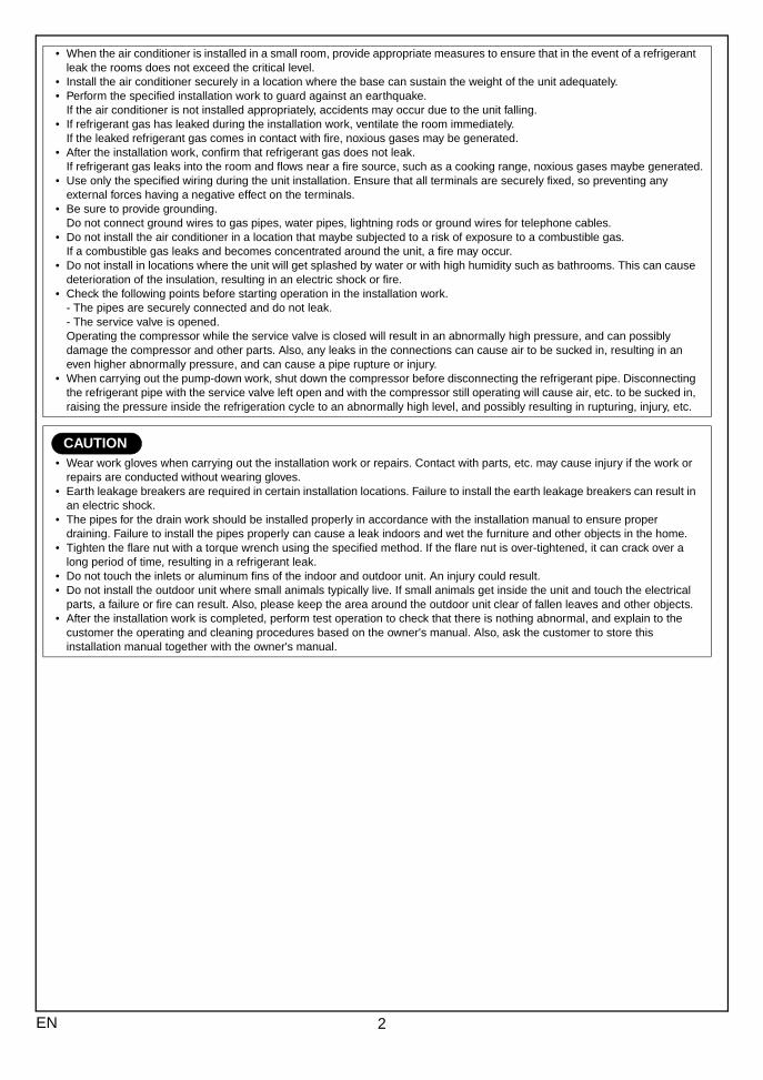
• When the air conditioner is installed in a small room, provide appropriate measures to ensure that in the event of a refrigerant leak the rooms does not exceed the critical level.
• Install the air conditioner securely in a location where the base can sustain the weight of the unit adequately.• Perform the specified installation work to guard against an earthquake.
If the air conditioner is not installed appropriately, accidents may occur due to the unit falling.• If refrigerant gas has leaked during the installation work, ventilate the room immediately.
If the leaked refrigerant gas comes in contact with fire, noxious gases may be generated.• After the installation work, confirm that refrigerant gas does not leak.
If refrigerant gas leaks into the room and flows near a fire source, such as a cooking range, noxious gases maybe generated.• Use only the specified wiring during the unit installation. Ensure that all terminals are securely fixed, so preventing any
external forces having a negative effect on the terminals.• Be sure to provide grounding.
Do not connect ground wires to gas pipes, water pipes, lightning rods or ground wires for telephone cables.• Do not install the air conditioner in a location that maybe subjected to a risk of exposure to a combustible gas.
If a combustible gas leaks and becomes concentrated around the unit, a fire may occur.• Do not install in locations where the unit will get splashed by water or with high humidity such as bathrooms. This can cause
deterioration of the insulation, resulting in an electric shock or fire.• Check the following points before starting operation in the installation work.
- The pipes are securely connected and do not leak.- The service valve is opened.Operating the compressor while the service valve is closed will result in an abnormally high pressure, and can possibly damage the compressor and other parts. Also, any leaks in the connections can cause air to be sucked in, resulting in an even higher abnormally pressure, and can cause a pipe rupture or injury.
• When carrying out the pump-down work, shut down the compressor before disconnecting the refrigerant pipe. Disconnecting the refrigerant pipe with the service valve left open and with the compressor still operating will cause air, etc. to be sucked in, raising the pressure inside the refrigeration cycle to an abnormally high level, and possibly resulting in rupturing, injury, etc.
CAUTION• Wear work gloves when carrying out the installation work or repairs. Contact with parts, etc. may cause injury if the work or
repairs are conducted without wearing gloves.• Earth leakage breakers are required in certain installation locations. Failure to install the earth leakage breakers can result in
an electric shock.• The pipes for the drain work should be installed properly in accordance with the installation manual to ensure proper
draining. Failure to install the pipes properly can cause a leak indoors and wet the furniture and other objects in the home.• Tighten the flare nut with a torque wrench using the specified method. If the flare nut is over-tightened, it can crack over a
long period of time, resulting in a refrigerant leak.• Do not touch the inlets or aluminum fins of the indoor and outdoor unit. An injury could result.• Do not install the outdoor unit where small animals typically live. If small animals get inside the unit and touch the electrical
parts, a failure or fire can result. Also, please keep the area around the outdoor unit clear of fallen leaves and other objects.• After the installation work is completed, perform test operation to check that there is nothing abnormal, and explain to the
customer the operating and cleaning procedures based on the owner's manual. Also, ask the customer to store this installation manual together with the owner's manual.
2EN
EN
GL
ISH
FR
AN
ÇA
ISD
EU
TS
CH
ITA
LIA
NO
ES
PAÑ
OL
ΕΛΛΗΝΙΚΗ
PO
RT
UG
UÊ
S##
#SW
###
RU
###
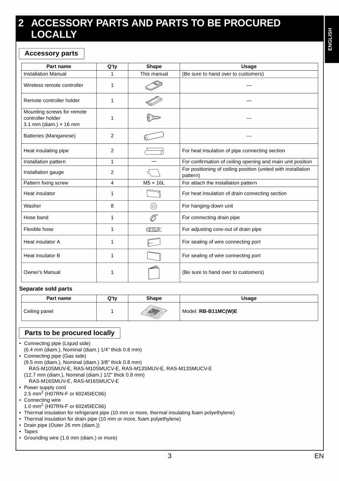
Separate sold parts
• Connecting pipe (Liquid side)(6.4 mm (diam.), Nominal (diam.) 1/4" thick 0.8 mm)
• Connecting pipe (Gas side)(9.5 mm (diam.), Nominal (diam.) 3/8" thick 0.8 mm)
RAS-M10SMUV-E, RAS-M10SMUCV-E, RAS-M13SMUV-E, RAS-M13SMUCV-E (12.7 mm (diam.), Nominal (diam.) 1/2" thick 0.8 mm)
RAS-M16SMUV-E, RAS-M16SMUCV-E• Power supply cord
2.5 mm2 (H07RN-F or 60245IEC66)• Connecting wire
1.0 mm2 (H07RN-F or 60245IEC66)• Thermal insulation for refrigerant pipe (10 mm or more, thermal insulating foam polyethylene)• Thermal insulation for drain pipe (10 mm or more, foam polyethylene)• Drain pipe (Outer 26 mm (diam.))• Tapes• Grounding wire (1.6 mm (diam.) or more)
2 ACCESSORY PARTS AND PARTS TO BE PROCURED LOCALLY
Accessory parts
Part name Q'ty Shape UsageInstallation Manual 1 This manual (Be sure to hand over to customers)
Wireless remote controller 1 —
Remote controller holder 1 —
Mounting screws for remote controller holder 3.1 mm (diam.) × 16 mm
1 —
Batteries (Manganese) 2 —
Heat insulating pipe 2 For heat insulation of pipe connecting section
Installation pattern 1 — For confirmation of ceiling opening and main unit position
Installation gauge 2For positioning of ceiling position (united with installation pattern)
Pattern fixing screw 4 M5 × 16L For attach the installation pattern
Heat insulator 1 For heat insulation of drain connecting section
Washer 8 For hanging-down unit
Hose band 1 For connecting drain pipe
Flexible hose 1 For adjusting core-out of drain pipe
Heat insulator A 1 For sealing of wire connecting port
Heat insulator B 1 For sealing of wire connecting port
Owner’s Manual 1 (Be sure to hand over to customers)
Part name Q'ty Shape Usage
Ceiling panel 1 Model: RB-B11MC(W)E
Parts to be procured locally
3 EN
###
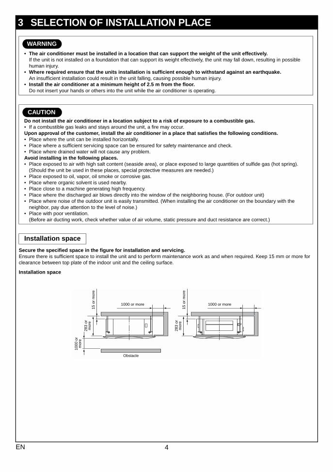
Secure the specified space in the figure for installation and servicing.Ensure there is sufficient space to install the unit and to perform maintenance work as and when required. Keep 15 mm or more for clearance between top plate of the indoor unit and the ceiling surface.
Installation space
3 SELECTION OF INSTALLATION PLACE
WARNING
• The air conditioner must be installed in a location that can support the weight of the unit effectively.If the unit is not installed on a foundation that can support its weight effectively, the unit may fall down, resulting in possible human injury.
• Where required ensure that the units installation is sufficient enough to withstand against an earthquake.An insufficient installation could result in the unit falling, causing possible human injury.
• Install the air conditioner at a minimum height of 2.5 m from the floor.Do not insert your hands or others into the unit while the air conditioner is operating.
CAUTIONDo not install the air conditioner in a location subject to a risk of exposure to a combustible gas.• If a combustible gas leaks and stays around the unit, a fire may occur.Upon approval of the customer, install the air conditioner in a place that satisfies the following conditions.• Place where the unit can be installed horizontally.• Place where a sufficient servicing space can be ensured for safety maintenance and check.• Place where drained water will not cause any problem.Avoid installing in the following places.• Place exposed to air with high salt content (seaside area), or place exposed to large quantities of sulfide gas (hot spring).
(Should the unit be used in these places, special protective measures are needed.)• Place exposed to oil, vapor, oil smoke or corrosive gas.• Place where organic solvent is used nearby.• Place close to a machine generating high frequency.• Place where the discharged air blows directly into the window of the neighboring house. (For outdoor unit)• Place where noise of the outdoor unit is easily transmitted. (When installing the air conditioner on the boundary with the
neighbor, pay due attention to the level of noise.)• Place with poor ventilation.
(Before air ducting work, check whether value of air volume, static pressure and duct resistance are correct.)
Installation space
15 o
r m
ore
283
or
mor
e
1000
or
mor
e
15 o
r m
ore
283
or
mor
e
1000 or more 1000 or more
Obstacle
4EN
EN
GL
ISH
FR
AN
ÇA
ISD
EU
TS
CH
ITA
LIA
NO
ES
PAÑ
OL
ΕΛΛΗΝΙΚΗ
PO
RT
UG
UÊ
S##
#SW
###
RU
###
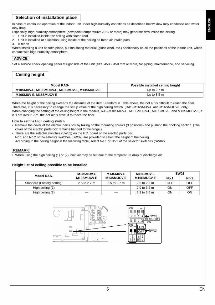
In case of continued operation of the indoor unit under high-humidity conditions as described below, dew may condense and water may drop.Especially, high-humidity atmosphere (dew point temperature: 23°C or more) may generate dew inside the ceiling.1. Unit is installed inside the ceiling with slated roof.2. Unit is installed at a location using inside of the ceiling as fresh air intake path.3. KitchenWhen installing a unit at such place, put insulating material (glass wool, etc.) additionally on all the positions of the indoor unit, which contact with high-humidity atmosphere.
ADVICE
Set a service check opening panel at right side of the unit (size: 450 × 450 mm or more) for piping, maintenance, and servicing.
When the height of the ceiling exceeds the distance of the item Standard in Table above, the hot air is difficult to reach the floor.Therefore, it is necessary to change the setup value of the high ceiling switch. (RAS-M16SMUV-E and M16SMUCV-E only)When changing the setting of the ceiling height in the models, RAS-M10SMUV-E, M10SMUCV-E, M13SMUV-E and M13SMUCV-E, if it is set over 2.7 m, the hot air is difficult to reach the floor.
How to set the High ceiling switch• Remove the cover of the electric parts box by taking off the mounting screws (3 positions) and pushing the hooking section. (The
cover of the electric parts box remains hanged to the hinge.)• There are the selector switches (SW02) on the P.C. board of the electric parts box.
No.1 and No.2 of the selector switches (SW02) are provided to select the height of the ceiling.According to the ceiling height in the following table, select No.1 or No.2 of the selector switches (SW02).
REMARK• When using the high ceiling (1) or (2), cold air may be felt due to the temperature drop of discharge air.
Height list of ceiling possible to be installed
Selection of installation place
Ceiling height
Model RAS- Possible installed ceiling heightM10SMUV-E, M10SMUCV-E, M13SMUV-E, M13SMUCV-E Up to 2.7 m
M16SMUV-E, M16SMUCV-E Up to 3.5 m
Model RAS-M10SMUV-E
M10SMUCV-EM13SMUV-E
M13SMUCV-EM16SMUV-E
M16SMUCV-ESW02
No.1 No.2Standard (Factory setting) 2.5 to 2.7 m 2.5 to 2.7 m 2.5 to 2.9 m OFF OFF
High ceiling (1) — — 2.9 to 3.2 m ON OFF
High ceiling (2) — — 3.2 to 3.5 m ON ON
5 EN
###
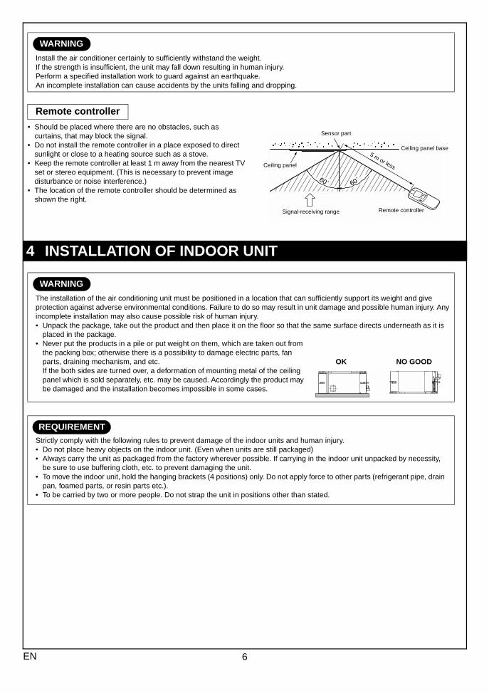
• Should be placed where there are no obstacles, such as curtains, that may block the signal.
• Do not install the remote controller in a place exposed to direct sunlight or close to a heating source such as a stove.
• Keep the remote controller at least 1 m away from the nearest TV set or stereo equipment. (This is necessary to prevent image disturbance or noise interference.)
• The location of the remote controller should be determined as shown the right.
WARNING
Install the air conditioner certainly to sufficiently withstand the weight. If the strength is insufficient, the unit may fall down resulting in human injury. Perform a specified installation work to guard against an earthquake. An incomplete installation can cause accidents by the units falling and dropping.
Remote controller
4 INSTALLATION OF INDOOR UNIT
WARNING
The installation of the air conditioning unit must be positioned in a location that can sufficiently support its weight and give protection against adverse environmental conditions. Failure to do so may result in unit damage and possible human injury. Any incomplete installation may also cause possible risk of human injury.• Unpack the package, take out the product and then place it on the floor so that the same surface directs underneath as it is
placed in the package.• Never put the products in a pile or put weight on them, which are taken out from
the packing box; otherwise there is a possibility to damage electric parts, fan parts, draining mechanism, and etc.If the both sides are turned over, a deformation of mounting metal of the ceiling panel which is sold separately, etc. may be caused. Accordingly the product may be damaged and the installation becomes impossible in some cases.
REQUIREMENTStrictly comply with the following rules to prevent damage of the indoor units and human injury.• Do not place heavy objects on the indoor unit. (Even when units are still packaged)• Always carry the unit as packaged from the factory wherever possible. If carrying in the indoor unit unpacked by necessity,
be sure to use buffering cloth, etc. to prevent damaging the unit.• To move the indoor unit, hold the hanging brackets (4 positions) only. Do not apply force to other parts (refrigerant pipe, drain
pan, foamed parts, or resin parts etc.).• To be carried by two or more people. Do not strap the unit in positions other than stated.
Ceiling panel
Remote controller
Sensor part
Signal-receiving range
Ceiling panel base5 m or less
NO GOODOK
6EN
EN
GL
ISH
FR
AN
ÇA
ISD
EU
TS
CH
ITA
LIA
NO
ES
PAÑ
OL
ΕΛΛΗΝΙΚΗ
PO
RT
UG
UÊ
S##
#SW
###
RU
###
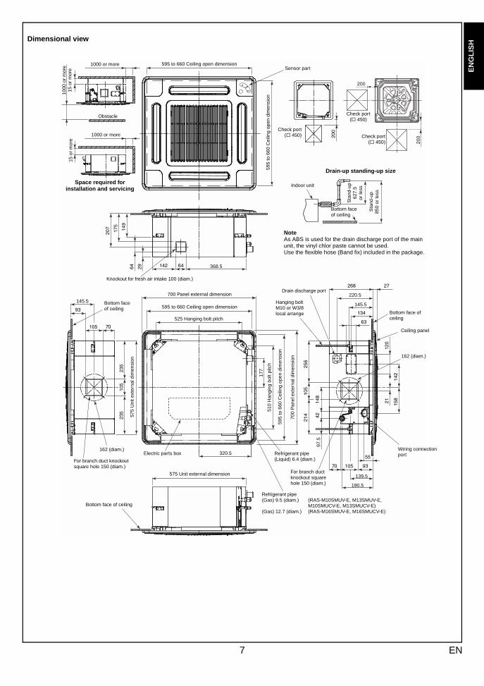
Dimensional view
1000 or more
Obstacle
1000
or
mor
e15
or
mor
e595 to 660 Ceiling open dimension
595
to 6
60 C
eilin
g op
en d
imen
sion
Knockout for fresh air intake 100 (diam.)
Space required for installation and servicing
Sensor part
Check port(! 450) Check port
(! 450)
Check port(! 450)
Drain-up standing-up size
Sta
nd-u
p85
0 or
less
Sta
nd-u
p62
7.5
or le
ss
Indoor unit
Bottom faceof ceiling
NoteAs ABS is used for the drain discharge port of the main unit, the vinyl chlor paste cannot be used.Use the flexible hose (Band fix) included in the package.
Bottom face of ceiling
162 (diam.)
For branch duct knockout square hole 150 (diam.)
575
Uni
t ext
erna
l dim
ensi
on
700 Panel external dimension
595 to 660 Ceiling open dimension
525 Hanging bolt pitch
510
Han
ging
bol
t pitc
h
595
to 6
60 C
eilin
g op
en d
imen
sion
700
Pan
el e
xter
nal d
imen
sion
Drain discharge port
Hanging bolt M10 or W3/8 local arrange
Refrigerant pipe (Liquid) 6.4 (diam.)
Refrigerant pipe(Gas) 9.5 (diam.) (RAS-M10SMUV-E, M13SMUV-E,
M10SMUCV-E, M13SMUCV-E)(Gas) 12.7 (diam.) (RAS-M16SMUV-E, M16SMUCV-E)
For branch duct knockout square hole 150 (diam.)
Bottom face of ceiling
575 Unit external dimension
162 (diam.)
Bottom face of ceiling
Ceiling panel
Wiring connection port
220.5
145.5
139.5
190.5
97.5
320.5
145.5
368.5
1000 or more
15 o
r m
ore
Electric parts box
177
7 EN
###
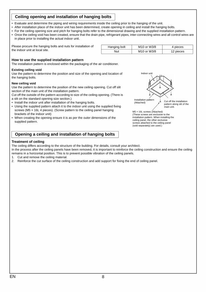
• Evaluate and determine the piping and wiring requirements inside the ceiling prior to the hanging of the unit.• After installation place of the indoor unit has been determined, create opening in ceiling and install the hanging bolts.• For the ceiling opening size and pitch for hanging bolts refer to the dimensional drawing and the supplied installation pattern.• Once the ceiling void has been created, ensure that the drain pipe, refrigerant pipes, inter-connecting wires and all control wires are
in place prior to installing the actual indoor unit.
Please procure the hanging bolts and nuts for installation of the indoor unit at local site.
How to use the supplied installation patternThe installation pattern is enclosed within the packaging of the air conditioner.
Existing ceiling voidUse the pattern to determine the position and size of the opening and location of the hanging bolts.
New ceiling voidUse the pattern to determine the position of the new ceiling opening. Cut off slit section of the main unit of the installation pattern.Cut off the outside of the pattern according to size of the ceiling opening. (There is a slit on the standard opening size section.)• Install the indoor unit after installation of the hanging bolts.• Using the supplied pattern attach it to the indoor unit using the supplied fixing
screws (M5 × 16L 4 pieces). (Screw pattern to the ceiling panel hanging brackets of the indoor unit)
• When creating the opening ensure it is as per the outer dimensions of the supplied pattern.
Treatment of ceilingThe ceiling differs according to the structure of the building. For details, consult your architect.In the process after the ceiling panels have been removed, it is important to reinforce the ceiling construction and ensure the ceiling remains in a horizontal position. This is to prevent possible vibration of the ceiling panels.1. Cut and remove the ceiling material.2. Reinforce the cut surface of the ceiling construction and add support for fixing the end of ceiling panel.
Ceiling opening and installation of hanging bolts
Opening a ceiling and installation of hanging bolts
Hanging bolt M10 or W3/8 4 pieces
Nut M10 or W3/8 12 pieces
Indoor unit
Installation pattern (Attached)
M5 × 16L screws (Attached)(These screws are exclusive to the installation pattern. When installing the ceiling panel, the other exclusive screws attached to the ceiling panel (sold separately) are used.)
Cut off the installation pattern along slit of the main unit.
8EN
EN
GL
ISH
FR
AN
ÇA
ISD
EU
TS
CH
ITA
LIA
NO
ES
PAÑ
OL
ΕΛΛΗΝΙΚΗ
PO
RT
UG
UÊ
S##
#SW
###
###R
U##
#
9 EN
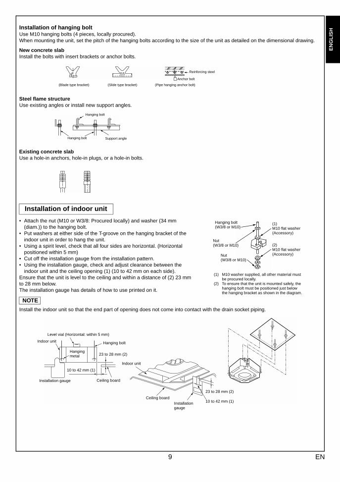
Installation of hanging boltUse M10 hanging bolts (4 pieces, locally procured).When mounting the unit, set the pitch of the hanging bolts according to the size of the unit as detailed on the dimensional drawing.
New concrete slabInstall the bolts with insert brackets or anchor bolts.
Steel flame structureUse existing angles or install new support angles.
Existing concrete slabUse a hole-in anchors, hole-in plugs, or a hole-in bolts.
• Attach the nut (M10 or W3/8: Procured locally) and washer (34 mm (diam.)) to the hanging bolt.
• Put washers at either side of the T-groove on the hanging bracket of the indoor unit in order to hang the unit.
• Using a spirit level, check that all four sides are horizontal. (Horizontal positioned within 5 mm)
• Cut off the installation gauge from the installation pattern.• Using the installation gauge, check and adjust clearance between the
indoor unit and the ceiling opening (1) (10 to 42 mm on each side).Ensure that the unit is level to the ceiling and within a distance of (2) 23 mm to 28 mm below.The installation gauge has details of how to use printed on it.
NOTE
Install the indoor unit so that the end part of opening does not come into contact with the drain socket piping.
Installation of indoor unit
(Blade type bracket) (Slide type bracket) (Pipe hanging anchor bolt)
Reinforcing steel
Anchor bolt
Hanging bolt Support angle
Hanging bolt
Hanging bolt (W3/8 or M10)
(1)M10 flat washer (Accessory)
(2)M10 flat washer (Accessory)
Nut(W3/8 or M10)
Nut(W3/8 or M10)
(1) M10 washer supplied, all other material must be procured locally.
(2) To ensure that the unit is mounted safely, the hanging bolt must be positioned just below the hanging bracket as shown in the diagram.
Level vial (Horizontal: within 5 mm)
Hanging boltIndoor unit
Ceiling board
23 to 28 mm (2)Hanging metal
10 to 42 mm (1)
Installation gauge
Indoor unit
Ceiling boardInstallation gauge
10 to 42 mm (1)
23 to 28 mm (2)
Install the ceiling panel after completion of the installation of the indoor unit, including all piping and wiring.Install the ceiling panel as per the supplied Installation Manual.Check the installation dimensions of the indoor unit and the ceiling opening are correct and then install.
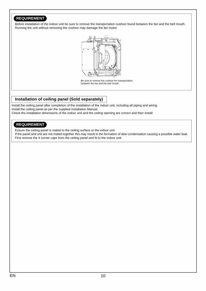
REQUIREMENTBefore installation of the indoor unit be sure to remove the transportation cushion found between the fan and the bell mouth.Running the unit without removing the cushion may damage the fan motor.
Installation of ceiling panel (Sold separately)
REQUIREMENTEnsure the ceiling panel is mated to the ceiling surface or the indoor unit.If the panel and unit are not mated together this may result in the formation of dew condensation causing a possible water leak.First remove the 4 corner caps from the ceiling panel and fit to the indoor unit.
Be sure to remove the cushion for transportation between the fan and the bell mouth.
10EN
EN
GL
ISH
FR
AN
ÇA
ISD
EU
TS
CH
ITA
LIA
NO
ES
PAÑ
OL
ΕΛΛΗΝΙΚΗ
PO
RT
UG
UÊ
S##
#SW
###
RU
###
The following materials for piping work and insulation are to be procured locally.
5 DRAIN PIPING WORK
CAUTION• Install the drain piping so that the water drains effectively.• Apply heat insulation to prevent dew condensation from forming.• Incorrectly installed pipework may result in a water leak.
Pipe material/Insulator and size
Pipe materialHard vinyl chloride pipe socket for VP25
Hard vinyl chloride pipe VP25 (Outer diameter 32 mm (diam.))
Insulator Foamed polyethylene foam, thickness: 10 mm or more
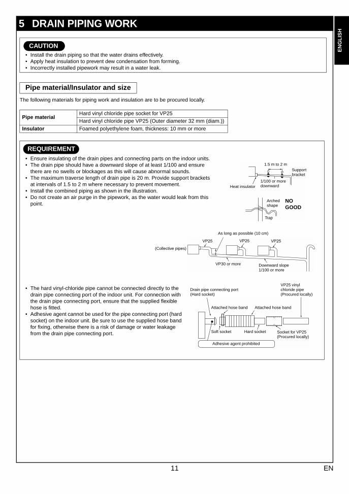
REQUIREMENT• Ensure insulating of the drain pipes and connecting parts on the indoor units.• The drain pipe should have a downward slope of at least 1/100 and ensure
there are no swells or blockages as this will cause abnormal sounds.• The maximum traverse length of drain pipe is 20 m. Provide support brackets
at intervals of 1.5 to 2 m where necessary to prevent movement.• Install the combined piping as shown in the illustration.• Do not create an air purge in the pipework, as the water would leak from this
point.
• The hard vinyl-chloride pipe cannot be connected directly to the drain pipe connecting port of the indoor unit. For connection with the drain pipe connecting port, ensure that the supplied flexible hose is fitted.
• Adhesive agent cannot be used for the pipe connecting port (hard socket) on the indoor unit. Be sure to use the supplied hose band for fixing, otherwise there is a risk of damage or water leakage from the drain pipe connecting port.
1.5 m to 2 m
Heat insulator1/100 or more downward
Support bracket
Trap
Arched shape
NO GOOD
As long as possible (10 cm)
(Collective pipes)
VP30 or more Downward slope 1/100 or more
Drain pipe connecting port (Hard socket)
Adhesive agent prohibited
VP25 vinyl chloride pipe(Procured locally)
Attached hose band Attached hose band
Soft socket Hard socket Socket for VP25 (Procured locally)
11 EN
###
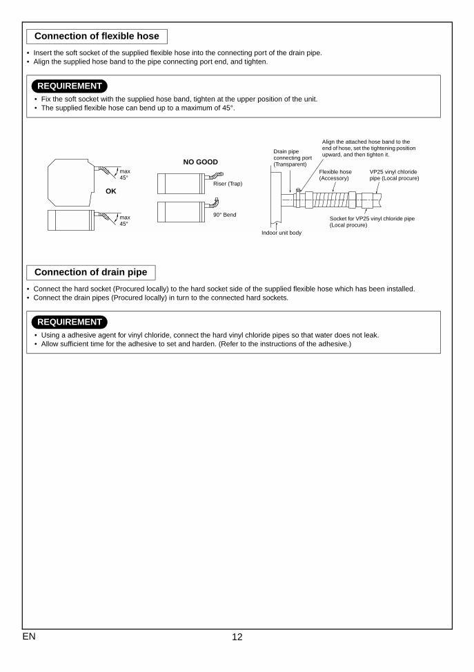
• Insert the soft socket of the supplied flexible hose into the connecting port of the drain pipe.• Align the supplied hose band to the pipe connecting port end, and tighten.
• Connect the hard socket (Procured locally) to the hard socket side of the supplied flexible hose which has been installed.• Connect the drain pipes (Procured locally) in turn to the connected hard sockets.
Connection of flexible hose
REQUIREMENT• Fix the soft socket with the supplied hose band, tighten at the upper position of the unit.• The supplied flexible hose can bend up to a maximum of 45°.
Connection of drain pipe
REQUIREMENT• Using a adhesive agent for vinyl chloride, connect the hard vinyl chloride pipes so that water does not leak.• Allow sufficient time for the adhesive to set and harden. (Refer to the instructions of the adhesive.)
NO GOOD
OK
max45°
max45°
Riser (Trap)
90° BendSocket for VP25 vinyl chloride pipe (Local procure)
VP25 vinyl chloride pipe (Local procure)
Flexible hose (Accessory)
Align the attached hose band to the end of hose, set the tightening position upward, and then tighten it.Drain pipe
connecting port (Transparent)
Indoor unit body
12EN
EN
GL
ISH
FR
AN
ÇA
ISD
EU
TS
CH
ITA
LIA
NO
ES
PAÑ
OL
ΕΛΛΗΝΙΚΗ
PO
RT
UG
UÊ
S##
#SW
###
RU
###
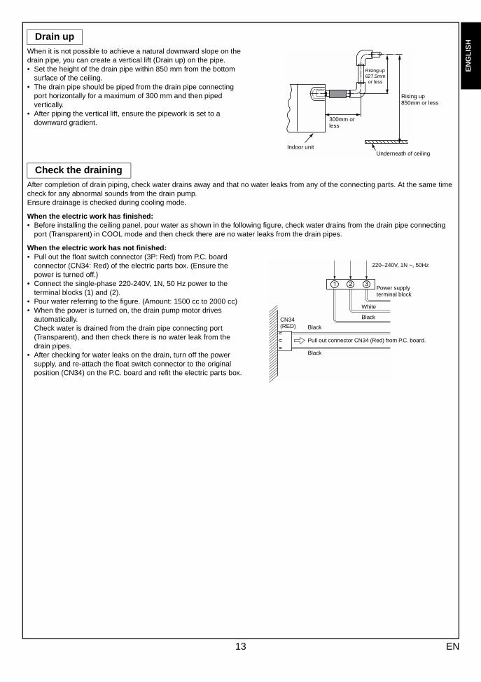
When it is not possible to achieve a natural downward slope on the drain pipe, you can create a vertical lift (Drain up) on the pipe.• Set the height of the drain pipe within 850 mm from the bottom
surface of the ceiling.• The drain pipe should be piped from the drain pipe connecting
port horizontally for a maximum of 300 mm and then piped vertically.
• After piping the vertical lift, ensure the pipework is set to a downward gradient.
After completion of drain piping, check water drains away and that no water leaks from any of the connecting parts. At the same time check for any abnormal sounds from the drain pump. Ensure drainage is checked during cooling mode.
When the electric work has finished:• Before installing the ceiling panel, pour water as shown in the following figure, check water drains from the drain pipe connecting
port (Transparent) in COOL mode and then check there are no water leaks from the drain pipes.
When the electric work has not finished:• Pull out the float switch connector (3P: Red) from P.C. board
connector (CN34: Red) of the electric parts box. (Ensure the power is turned off.)
• Connect the single-phase 220-240V, 1N, 50 Hz power to the terminal blocks (1) and (2).
• Pour water referring to the figure. (Amount: 1500 cc to 2000 cc)• When the power is turned on, the drain pump motor drives
automatically.Check water is drained from the drain pipe connecting port (Transparent), and then check there is no water leak from the drain pipes.
• After checking for water leaks on the drain, turn off the power supply, and re-attach the float switch connector to the original position (CN34) on the P.C. board and refit the electric parts box.
Drain up
Check the draining
Indoor unit
300mm or less
Underneath of ceiling
Rising up 850mm or less
Rising up 627.5mm
or less
Black
Pull out connector CN34 (Red) from P.C. board.
BlackCN34 (RED)
Black
White
Power supply terminal block
220–240V, 1N ~, 50Hz
13 EN
###
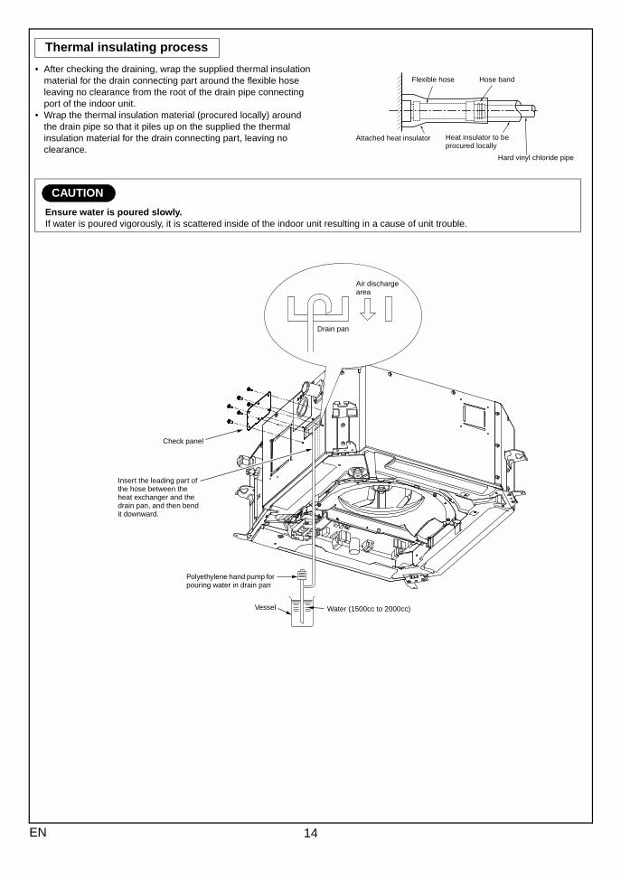
• After checking the draining, wrap the supplied thermal insulation material for the drain connecting part around the flexible hose leaving no clearance from the root of the drain pipe connecting port of the indoor unit.
• Wrap the thermal insulation material (procured locally) around the drain pipe so that it piles up on the supplied the thermal insulation material for the drain connecting part, leaving no clearance.
Thermal insulating process
CAUTION
Ensure water is poured slowly.If water is poured vigorously, it is scattered inside of the indoor unit resulting in a cause of unit trouble.
Flexible hose
Attached heat insulator
Hose band
Heat insulator to be procured locally
Hard vinyl chloride pipe
Drain pan
Air discharge area
Check panel
Insert the leading part of the hose between the heat exchanger and the drain pan, and then bend it downward.
Polyethylene hand pump for pouring water in drain pan
Vessel Water (1500cc to 2000cc)
14EN
EN
GL
ISH
FR
AN
ÇA
ISD
EU
TS
CH
ITA
LIA
NO
ES
PAÑ
OL
ΕΛΛΗΝΙΚΗ
PO
RT
UG
UÊ
S##
#SW
###
RU
###
1. If the outdoor units are to be mounted on a wall, make sure that the supporting platform is sufficiently strong. The platform should be designed and manufactured to maintain its strength over a long period of time, and sufficient consideration should be given to ensuring that the outdoor unit will not fall.
2. Use copper pipe with 0.8 mm or more thickness.3. Flare nut and flare works are different from those of the conventional refrigerant.Take out the flare nut attached to the main unit of the air conditioner, and use it.
They vary according to the outdoor unit.For details, refer to the Installation Manual attached to the outdoor unit.
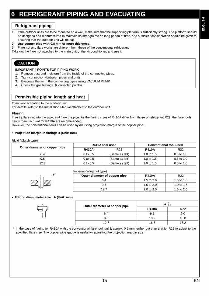
FlaringInsert a flare nut into the pipe, and flare the pipe. As the flaring sizes of R410A differ from those of refrigerant R22, the flare tools newly manufactured for R410A are recommended.However, the conventional tools can be used by adjusting projection margin of the copper pipe.
• Projection margin in flaring: B (Unit: mm)
Rigid (Clutch type)
Imperial (Wing nut type)
• Flaring diam. meter size : A (Unit: mm)
* In the case of flaring for R410A with the conventional flare tool, pull it approx. 0.5 mm further out than that for R22 to adjust to the specified flare size. The copper pipe gauge is useful for adjusting the projection margin size.
6 REFRIGERANT PIPING AND EVACUATING
Refrigerant piping
CAUTION
IMPORTANT 4 POINTS FOR PIPING WORK1. Remove dust and moisture from the inside of the connecting pipes.2. Tight connection (between pipes and unit)3. Evacuate the air in the connecting pipes using VACUUM PUMP.4. Check the gas leakage. (Connected points)
Permissible piping length and heat
Outer diameter of copper pipeR410A tool used Conventional tool used
R410A R22 R410A R22
6.4 0 to 0.5 (Same as left) 1.0 to 1.5 0.5 to 1.0
9.5 0 to 0.5 (Same as left) 1.0 to 1.5 0.5 to 1.0
12.7 0 to 0.5 (Same as left) 1.0 to 1.5 0.5 to 1.0
Outer diameter of copper pipe R410A R22
6.4 1.5 to 2.0 1.0 to 1.5
9.5 1.5 to 2.0 1.0 to 1.5
12.7 2.0 to 2.5 1.5 to 2.0
Outer diameter of copper pipe A
R410A R22
6.4 9.1 9.0
9.5 13.2 13.0
12.7 16.6 16.2
+0–0.4
15 EN
###
Tightening connection
(Unit: N·m)
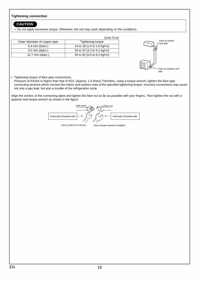
• Tightening torque of flare pipe connections. Pressure of R410A is higher than that of R22. (Approx. 1.6 times) Therefore, using a torque wrench, tighten the flare pipe connecting sections which connect the indoor and outdoor units of the specified tightening torque. Incorrect connections may cause not only a gas leak, but also a trouble of the refrigeration cycle.
Align the centers of the connecting pipes and tighten the flare nut as far as possible with your fingers. Then tighten the nut with a spanner and torque wrench as shown in the figure.
CAUTION• Do not apply excessive torque. Otherwise, the nut may crack depending on the conditions.
Outer diameter of copper pipe Tightening torque
6.4 mm (diam.) 14 to 18 (1.4 to 1.8 kgf·m)
9.5 mm (diam.) 33 to 42 (3.3 to 4.2 kgf·m)
12.7 mm (diam.) 50 to 62 (5.0 to 6.2 kgf·m)
Flare at indoor unit side
Flare at outdoor unit side
Half union Flare nut
Externally threaded side
Use a wrench to secure.
Internally threaded side
Use a torque wrench to tighten.
16EN
EN
GL
ISH
FR
AN
ÇA
ISD
EU
TS
CH
ITA
LIA
NO
ES
PAÑ
OL
ΕΛΛΗΝΙΚΗ
PO
RT
UG
UÊ
S##
#SW
###
RU
###
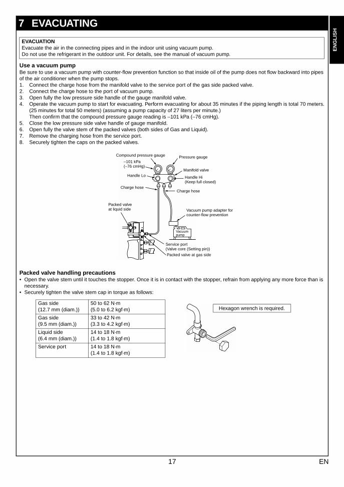
Use a vacuum pumpBe sure to use a vacuum pump with counter-flow prevention function so that inside oil of the pump does not flow backward into pipes of the air conditioner when the pump stops.1. Connect the charge hose from the manifold valve to the service port of the gas side packed valve.2. Connect the charge hose to the port of vacuum pump.3. Open fully the low pressure side handle of the gauge manifold valve.4. Operate the vacuum pump to start for evacuating. Perform evacuating for about 35 minutes if the piping length is total 70 meters.
(25 minutes for total 50 meters) (assuming a pump capacity of 27 liters per minute.)Then confirm that the compound pressure gauge reading is –101 kPa (–76 cmHg).
5. Close the low pressure side valve handle of gauge manifold.6. Open fully the valve stem of the packed valves (both sides of Gas and Liquid).7. Remove the charging hose from the service port.8. Securely tighten the caps on the packed valves.
Packed valve handling precautions• Open the valve stem until it touches the stopper. Once it is in contact with the stopper, refrain from applying any more force than is
necessary.• Securely tighten the valve stem cap in torque as follows:
7 EVACUATING
EVACUATIONEvacuate the air in the connecting pipes and in the indoor unit using vacuum pump.Do not use the refrigerant in the outdoor unit. For details, see the manual of vacuum pump.
Compound pressure gauge
–101 kPa (–76 cmHg)
Handle Lo
Charge hose
Pressure gauge
Manifold valve
Handle Hi (Keep full closed)
Charge hose
Vacuum pump adapter for counter-flow prevention
Vacuum pump
Packed valve at liquid side
Packed valve at gas side
Service port(Valve core (Setting pin))
Hexagon wrench is required.Gas side(12.7 mm (diam.))
50 to 62 N·m(5.0 to 6.2 kgf·m)
Gas side(9.5 mm (diam.))
33 to 42 N·m(3.3 to 4.2 kgf·m)
Liquid side(6.4 mm (diam.))
14 to 18 N·m(1.4 to 1.8 kgf·m)
Service port 14 to 18 N·m(1.4 to 1.8 kgf·m)
17 EN
###
How to wire1. Connect the connecting wire to the terminal as identified with their respective numbers on the terminal block of indoor and
outdoor unit. 1.0 mm2 (H07 RN-F or 60245 IEC 66)
2. Insulate the unsheathed redundant cords (conductors) with electrical insulation tape. Process them so that they do not touch any electrical or metal parts.
3. For inter-unit wiring, do not use a wire jointed to another on the way.
8 ELECTRICAL WORK
WARNING
1. Using the specified wires, ensure to connect the wires, and fix wires securely so that the external tension to the wires do not affect the connecting part of the terminals.Incomplete connection or fixation may cause a fire, etc.
2. Be sure to connect earth wire. (Grounding work)Do not connect the earth wire to gas pipe, city water pipe, lightning rod, or the earth wire of telephone. Incomplete grounding causes an electric shock.
3. For electric work, strictly follow the Local Regulation in each country and the Installation Manual, and use an exclusive circuit.Capacity shortage of power circuit or incomplete installation may cause an electric shock or a fire.
CAUTION• This indoor unit has no power cord.• If incorrect/incomplete wiring is carried out, it will cause an electrical fire or smoke.• Be sure to install an earth leakage breaker that is not tripped by shock waves.
If an earth leakage breaker is not installed, an electric shock may be caused.• Be sure to use the cord clamps attached to the product.• Do not damage or scratch the conductive core and inner insulator of power and inter-connecting wires when peeling them.• Be sure to comply with local regulations on running the wire from outdoor unit to indoor unit (size of wire and wiring method
etc.)• Use the power cord and Inter-connecting cable of specified thickness, type, and protective devices required.
REQUIREMENT• Appliance shall be installed in accordance with national wiring regulations.• For wiring of power supply of the outdoor units, follow the Installation Manual of each outdoor unit.• Perform the electric wiring so that it does not come to contact with the high-temperature part of the pipe. The coating may
melt resulting in an accident.• After connecting wires to the terminal blocks, provide a trap and fix wires with the cord clamp.• Run the refrigerant piping line and control wiring line in the same line.• Do not turn on the power of the indoor unit until vacuuming of the refrigerant pipes completes.
18EN
EN
GL
ISH
FR
AN
ÇA
ISD
EU
TS
CH
ITA
LIA
NO
ES
PAÑ
OL
ΕΛΛΗΝΙΚΗ
PO
RT
UG
UÊ
S##
#SW
###
RU
###
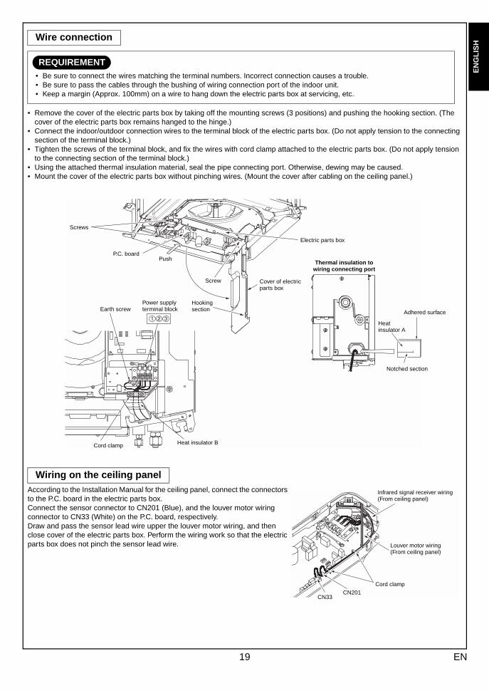
• Remove the cover of the electric parts box by taking off the mounting screws (3 positions) and pushing the hooking section. (The cover of the electric parts box remains hanged to the hinge.)
• Connect the indoor/outdoor connection wires to the terminal block of the electric parts box. (Do not apply tension to the connecting section of the terminal block.)
• Tighten the screws of the terminal block, and fix the wires with cord clamp attached to the electric parts box. (Do not apply tension to the connecting section of the terminal block.)
• Using the attached thermal insulation material, seal the pipe connecting port. Otherwise, dewing may be caused.• Mount the cover of the electric parts box without pinching wires. (Mount the cover after cabling on the ceiling panel.)
According to the Installation Manual for the ceiling panel, connect the connectors to the P.C. board in the electric parts box.Connect the sensor connector to CN201 (Blue), and the louver motor wiring connector to CN33 (White) on the P.C. board, respectively.Draw and pass the sensor lead wire upper the louver motor wiring, and then close cover of the electric parts box. Perform the wiring work so that the electric parts box does not pinch the sensor lead wire.
Wire connection
REQUIREMENT• Be sure to connect the wires matching the terminal numbers. Incorrect connection causes a trouble.• Be sure to pass the cables through the bushing of wiring connection port of the indoor unit.• Keep a margin (Approx. 100mm) on a wire to hang down the electric parts box at servicing, etc.
Wiring on the ceiling panel
Electric parts box
Cover of electric parts box
Thermal insulation to wiring connecting port
Hooking section
Screw
P.C. board
Screws
Push
Earth screwPower supply terminal block
Cord clamp Heat insulator B
Adhered surface
Heat insulator A
Notched section
Louver motor wiring(From ceiling panel)
Infrared signal receiver wiring(From ceiling panel)
Cord clampCN201
CN33
19 EN
###
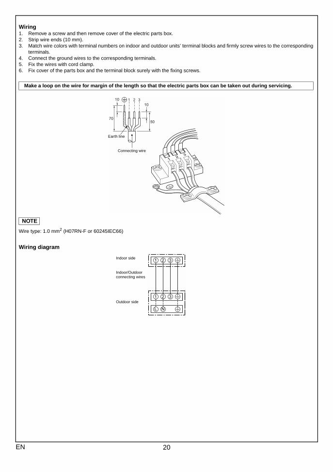
Wiring1. Remove a screw and then remove cover of the electric parts box.2. Strip wire ends (10 mm).3. Match wire colors with terminal numbers on indoor and outdoor units’ terminal blocks and firmly screw wires to the corresponding
terminals.4. Connect the ground wires to the corresponding terminals.5. Fix the wires with cord clamp.6. Fix cover of the parts box and the terminal block surely with the fixing screws.
NOTE
Wire type: 1.0 mm2 (H07RN-F or 60245IEC66)
Wiring diagram
Make a loop on the wire for margin of the length so that the electric parts box can be taken out during servicing.
Earth line
Connecting wire
Indoor side
Indoor/Outdoor connecting wires
Outdoor side
20EN
EN
GL
ISH
FR
AN
ÇA
ISD
EU
TS
CH
ITA
LIA
NO
ES
PAÑ
OL
ΕΛΛΗΝΙΚΗ
PO
RT
UG
UÊ
S##
#SW
###
RU
###
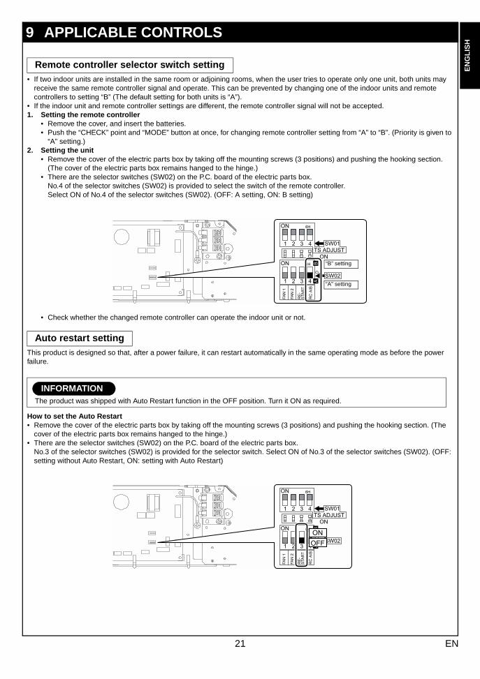
• If two indoor units are installed in the same room or adjoining rooms, when the user tries to operate only one unit, both units may receive the same remote controller signal and operate. This can be prevented by changing one of the indoor units and remote controllers to setting “B” (The default setting for both units is “A”).
• If the indoor unit and remote controller settings are different, the remote controller signal will not be accepted.1. Setting the remote controller
• Remove the cover, and insert the batteries.• Push the “CHECK” point and “MODE” button at once, for changing remote controller setting from “A” to “B”. (Priority is given to
“A” setting.)2. Setting the unit
• Remove the cover of the electric parts box by taking off the mounting screws (3 positions) and pushing the hooking section. (The cover of the electric parts box remains hanged to the hinge.)
• There are the selector switches (SW02) on the P.C. board of the electric parts box.No.4 of the selector switches (SW02) is provided to select the switch of the remote controller. Select ON of No.4 of the selector switches (SW02). (OFF: A setting, ON: B setting)
• Check whether the changed remote controller can operate the indoor unit or not.
This product is designed so that, after a power failure, it can restart automatically in the same operating mode as before the power failure.
How to set the Auto Restart• Remove the cover of the electric parts box by taking off the mounting screws (3 positions) and pushing the hooking section. (The
cover of the electric parts box remains hanged to the hinge.)• There are the selector switches (SW02) on the P.C. board of the electric parts box.
No.3 of the selector switches (SW02) is provided for the selector switch. Select ON of No.3 of the selector switches (SW02). (OFF: setting without Auto Restart, ON: setting with Auto Restart)
9 APPLICABLE CONTROLS
Remote controller selector switch setting
Auto restart setting
INFORMATIONThe product was shipped with Auto Restart function in the OFF position. Turn it ON as required.
“B” setting
“A” setting
21 EN
###
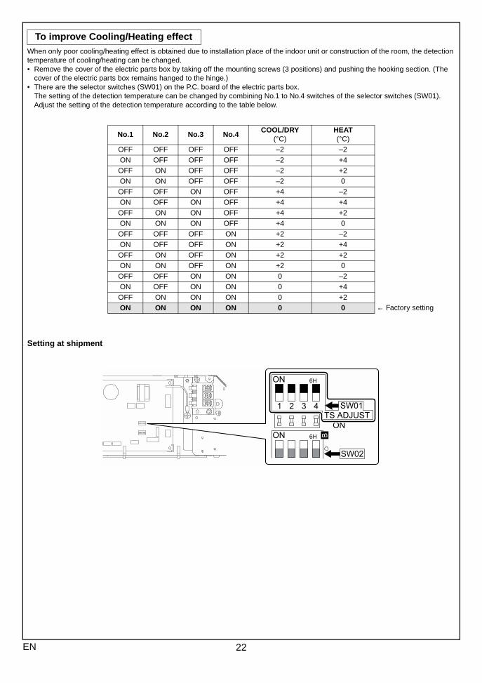
When only poor cooling/heating effect is obtained due to installation place of the indoor unit or construction of the room, the detection temperature of cooling/heating can be changed.• Remove the cover of the electric parts box by taking off the mounting screws (3 positions) and pushing the hooking section. (The
cover of the electric parts box remains hanged to the hinge.)• There are the selector switches (SW01) on the P.C. board of the electric parts box.
The setting of the detection temperature can be changed by combining No.1 to No.4 switches of the selector switches (SW01). Adjust the setting of the detection temperature according to the table below.
Setting at shipment
To improve Cooling/Heating effect
No.1 No.2 No.3 No.4COOL/DRY
(°C) HEAT(°C)
OFF OFF OFF OFF –2 –2
ON OFF OFF OFF –2 +4
OFF ON OFF OFF –2 +2
ON ON OFF OFF –2 0
OFF OFF ON OFF +4 –2
ON OFF ON OFF +4 +4
OFF ON ON OFF +4 +2
ON ON ON OFF +4 0
OFF OFF OFF ON +2 –2
ON OFF OFF ON +2 +4
OFF ON OFF ON +2 +2
ON ON OFF ON +2 0
OFF OFF ON ON 0 –2
ON OFF ON ON 0 +4
OFF ON ON ON 0 +2
ON ON ON ON 0 0 ← Factory setting
22EN
EN
GL
ISH
FR
AN
ÇA
ISD
EU
TS
CH
ITA
LIA
NO
ES
PAÑ
OL
ΕΛΛΗΝΙΚΗ
PO
RT
UG
UÊ
S##
#SW
###
RU
###
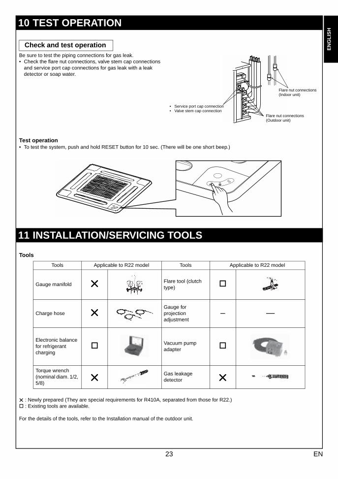
Be sure to test the piping connections for gas leak.• Check the flare nut connections, valve stem cap connections
and service port cap connections for gas leak with a leak detector or soap water.
Test operation• To test the system, push and hold RESET button for 10 sec. (There will be one short beep.)
Tools
: Newly prepared (They are special requirements for R410A, separated from those for R22.) " : Existing tools are available.
For the details of the tools, refer to the Installation manual of the outdoor unit.
10 TEST OPERATION
Check and test operation
11 INSTALLATION/SERVICING TOOLS
Tools Applicable to R22 model Tools Applicable to R22 model
Gauge manifoldFlare tool (clutch type) "
Charge hoseGauge for projection adjustment
– —
Electronic balance for refrigerant charging
" Vacuum pump adapter "
Torque wrench (nominal diam. 1/2, 5/8)
Gas leakage detector
• Service port cap connection• Valve stem cap connection
Flare nut connections (Outdoor unit)
Flare nut connections (Indoor unit)
23 EN
###
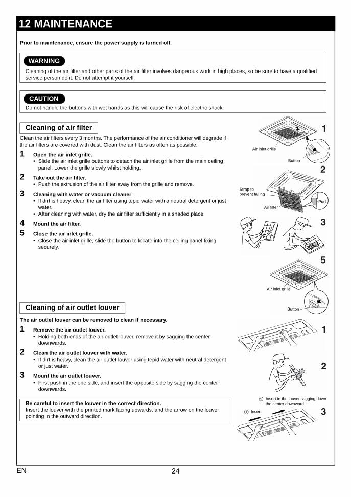
Prior to maintenance, ensure the power supply is turned off.
Clean the air filters every 3 months. The performance of the air conditioner will degrade if the air filters are covered with dust. Clean the air filters as often as possible.
1 Open the air inlet grille.• Slide the air inlet grille buttons to detach the air inlet grille from the main ceiling
panel. Lower the grille slowly whilst holding.
2 Take out the air filter.• Push the extrusion of the air filter away from the grille and remove.
3 Cleaning with water or vacuum cleaner• If dirt is heavy, clean the air filter using tepid water with a neutral detergent or just
water.• After cleaning with water, dry the air filter sufficiently in a shaded place.
4 Mount the air filter.
5 Close the air inlet grille.• Close the air inlet grille, slide the button to locate into the ceiling panel fixing
securely.
The air outlet louver can be removed to clean if necessary.
1 Remove the air outlet louver.• Holding both ends of the air outlet louver, remove it by sagging the center
downwards.
2 Clean the air outlet louver with water.• If dirt is heavy, clean the air outlet louver using tepid water with neutral detergent
or just water.
3 Mount the air outlet louver.• First push in the one side, and insert the opposite side by sagging the center
downwards.
12 MAINTENANCE
WARNING
Cleaning of the air filter and other parts of the air filter involves dangerous work in high places, so be sure to have a qualified service person do it. Do not attempt it yourself.
CAUTIONDo not handle the buttons with wet hands as this will cause the risk of electric shock.
Cleaning of air filter
Cleaning of air outlet louver
Be careful to insert the louver in the correct direction.Insert the louver with the printed mark facing upwards, and the arrow on the louver pointing in the outward direction.
Air inlet grille
Button
Air filter
Strap to prevent falling
Air inlet grille
Button
Push
b Insert in the louver sagging down the center downward.
a Insert
24EN

EH72957101-b