NASHIRA I LIBRETTO ISTRUZIONI - neri.biz · plinto di fondazione foundation plinth massif...
36
Rev. A - 2014 NASHIRA I GB F D E LIBRETTO ISTRUZIONI PALI INSTRUCTION BOOKLET OF POSTS NOTICE DE MONTAGE DES CANDELABRES INSTALLATIONSANLEITUNG FÜR MASTEN MANUAL DE INSTRUCCIONES PARA POSTES I GB F D E ATTENZIONE - CAUTION ATTENTION - ACHTUNG ATENCIÓN Questo manuale va letto e conservato con molta attenzione This manual should be read with attention and kept with great care Ce manuel doit être lu très attentivement et soigneusement conservé Die Anleitung sollte mit großer Aufmerksamkeit gelesen und aufbewahrt werden Leer este manual con atención y con- servarlo en un buen estado.
Transcript of NASHIRA I LIBRETTO ISTRUZIONI - neri.biz · plinto di fondazione foundation plinth massif...
Rev. A - 2014
NASHIRA I
GB
F
D
E
LIBRETTO ISTRUZIONIPALI
INSTRUCTION BOOKLETOF POSTS
NOTICE DE MONTAGE DES CANDELABRES
INSTALLATIONSANLEITUNGFÜR MASTEN
MANUAL DE INSTRUCCIONES PARA POSTES
I
GB
F
D
E
ATTENZIONE - CAUTIONATTENTION - ACHTUNG ATENCIÓNQuesto manuale va lettoe conservato con molta attenzione
This manual should be read withattention and kept with great care
Ce manuel doit être lu très attentivement et soigneusement conservé
Die Anleitung sollte mit großerAufmerksamkeit gelesen undaufbewahrt werden
Leer este manual con atención y con-servarlo en un buen estado.
2
NERI S.p.A. - S.S. Emilia 1622 - 47020 Longiano - FC - Italy - Tel. +39 0547 652111 - Fax +39 0547 54074 - [email protected] - www.neri.biz
Certificato/Certificate 9105.DONE
ISO 9001:2008
Certificato/Certificate9191.NER1
ISO 14001:2004
Questo manuale è soggetto a copyright © 2014. Tutti i diritti sono riservati. E’ vietata la riproduzione anche parziale di esso senza il consenso scritto della Neri spa.
La Neri spa si riserva il diritto di apportare modifiche ai propri prodotti e alla documentazione senza obbligo di preavviso.
This manual is subject to copyright © 2014. All rights reserved. Reproduction of this manual, even partially, is forbidden without written consent from Neri spa.
Neri spa reserves the right to modify its products and documentation without obligation to give prior warning.
Ce manuel fait l’objet d’un copyright © 2014. Tous droits réservés. Ce manuel ne peut être reproduit, même partiellement, sans l’accord écrit de Neri spa.
Neri spa se réserve le droit d’apporter toutes modifications à ses produits et à la documentation sans préavis.
Dieses Handbuch unterliegt dem Copyright © 2014. Alle Rechte vorbehalten. Seine auch auszugsweise Reproduktion ohne schriftliche Zustimmung der Neri spa ist verboten.
Die Neri spa behält sich das Recht vor, an ihren Produkten und der Dokumentation Veränderungen vorzunehmen, ohne dies vorher ankündigen zu müssen.
Este manual está protegido por derechos de propiedad intelectual © 2014. Todos los derechos reservados. Se prohíbe su reproducción incluso parcial sin autorización por escrito de la empresa Neri spa.
Neri spa se reserva el derecho de aportar cambios a sus productos y a la documentación sin obligación de aviso previo.
Autori: Isacco Neri - Titolo: Libretto Istruzioni Pali Nashira - Pubblicatore: Neri spaProgetto e coordinamento grafico: Daniele Lombardi - Stampa: Grafiche MDM srl, Forlì FC, ottobre 2014.Tutti i diritti riservati. E’ fatto espresso divieto a qualunque riproduzione parziale o totale del presente testo.
© 2014, DESIGN PATENTED, PRINTED IN ITALY

3
www.neri.biz
I
I
I
I
I
I
I
I
I
I
I
I
GB
GB
GB
GB
GB
GB
GB
GB
GB
GB
GB
GB
F
F
F
F
F
F
F
F
F
F
F
F
D
D
D
D
D
D
D
D
D
D
D
D
E
E
E
E
E
E
E
E
E
E
E
E
IGBFDE
SIMBOLI E ETICHETTA SYMBOLS AND LABELSYMBOLES ET ETIQUETTESYMBOLE UND AUFKLEBERSÍMBOLOS Y ETIQUETAS
1°pag 4
NOTE GENERALI ALLA CONSEGNA GENERAL NOTES ON DELIVERYCONSIGNES GÉNÉRALES À LA LIVRAISON ALLGEMEINE HINWEISE BEI DER LIEFERUNGNOTAS GENERALES DE ENTREGA
2°pag 5
PRESCRIZIONI DI SICUREZZA SAFETY PRECAUTIONS PRESCRIPTIONS DE SECURITE SICHERHEITSVORSCHRIFTEN NORMAS DE SEGURIDAD
3°pag 6
DISIMBALLO ANIME PALIUNPACKING POST CORESDEBALLAGE AMES DE CANDELABREAUSPACKEN DIE KERNMASTENDESEMBALAJE DE ALMAS PARA POSTES
4°pag 7
SISTEMA DI FISSAGGIO - MURATURAFIXING SYSTEM - CEMENTING INSYSTEME D’ANCRAGE - SCELLEMENT DIRECTBEFESTIGUNGSSYSTEM – EINMAUERNSISTEMA DE FIJACIÓN-MURAL
5°pag 8
SISTEMA DI FISSAGGIO - FLANGIAFIXING SYSTEM - FLANGESYSTEME D’ANCRAGE - SEMELLE DE FIXATIONBEFESTIGUNGSSYSTEM – FLANSCHSISTEMAS DE FIJACIÓN-BRIDA
6°pag 9
INSTALLAZIONE GUAINA PROTETTIVAFITTING OF PROTECTIVE SHEATHINSTALLATION GAINE DE PROTECTIONINSTALLATION DES SCHUTZMANTELSINSTALACIÓN DE FUNDA PROTECTORA
7°pag 10-11
PLINTO DI FONDAZIONEFOUNDATION PLINTHMASSIF D’ANCRAGEFUNDAMENTSOCKELPLINTO DE CIMENTACIÓN
8°pag 12
IMBRACATURA PALOPOLE SLINGINGÉLINGAGE CANDÉLABREANSCHLAG - LICHTMASTESLINGADO DEL POSTE
9°pag 13
MESSA A TERRRAGROUND CONNECTIONMISE A LA TERREERDUNGPUESTA A TIERRA
11°pag 17
PROTEZIONI FINALIFINAL PROTECTIONPROTECTIONS FINALESSCHUTZBEHANDLUNGPROTECCIÓN FINAL
12°pag 17
INSTALLAZIONE ANIME PALIINSTALLATION POST CORESINSTALLATION DES AMES DE CANDELABREINSTALLATION FÜR DIE KERNMASTENINSTALACIÓN DE ALMAS PARA POSTES
10°pag 14-16
IMBRACATURAHARNESSINGÉLINGAGEANSCHLAGEN ESLINGADO
13°pag 19
I
I
I
I
I
I
I
I
GB
GB
GB
GB
GB
GB
GB
GB
F
F
F
F
F
F
F
F
D
D
D
D
D
D
D
D
E
E
E
E
E
E
E
E
INSTALLAZIONE CIME 4201.025/G, 4301.025/G, 4401.035/G, 4101.100TOP SECTION INSTALLATION 4201.025/G, 4301.025/G, 4401.035/G, 4101.100INSTALLATION BOUQUETS 44201.025/G, 4301.025/G, 4401.035/G, 4101.100INSTALLATION KRONEN 4201.025/G, 4301.025/G, 4401.035/G, 4101.100INSTALACIÓN DE CIMAS 4201.025/G, 4301.025/G, 4401.035/G, 4101.100
ASSEMBLAGGIO PASTORALI AD UN BRACCIOASSEMBLY OF ONE-ARM PASTORAL ELEMENTSASSEMBLAGE CROSSES À UN BRASMONTAGE EINZELNER AUSLEGERENSAMBLAJE DE BÁCULOS CON UN BRAZO
INSTALLAZIONE CIME 4202.024/G, 4302.024/G, 4302.034/G, 4402.034/GTOP SECTION INSTALLATION 4202.024/G, 4302.024/G, 4302.034/G, 4402.034/GINSTALLATION BOUQUETS 4202.024/G, 4302.024/G, 4302.034/G, 4402.034/GINSTALLATION KRONEN 4202.024/G, 4302.024/G, 4302.034/G, 4402.034/GINSTALACIÓN DE CIMAS 4202.024/G, 4302.024/G, 4302.034/G, 4402.034/G
ASSEMBLAGGIO PASTORALI A PIU’ BRACCIASSEMBLY OF MULTIPLE-ARM PASTORAL ELEMENTSASSEMBLAGE CROSSES À PLUSIEURS BRASMONTAGE MEHRERE AUSLEGERENSAMBLAJE DE BÁCULOS CON VARIOS BRAZOS
INSTALLAZIONE CIMA TERMINALEINSTALLATION OF END TOP SECTIONINSTALLATION BOUQUET TERMINALINSTALLATION DES SPITZENENDSTÜCKSINSTALACIÓN DE LA CIMA TERMINAL
IMBRACATURA E INSTALLAZIONE PASTORALIHARNESSING AND INSTALLATION OF PASTORAL ELEMENTSÉLINGAGE ET INSTALLATION CROSSESANSCHLAGEN UND INSTALLIEREN DER AUSLEGERESLINGADO E INSTALACIÓN DE LOS BÁCULOS
INSTALLAZIONEINSTALLATIONINSTALLATIONINSTALLIEREN INSTALACIÓN
CONTROLLI FINALI E MANUTENZIONEFINAL CHECKS AND MAINTENANCECONTRÔLES FINALS ET ENTRETIENENDKONTROLLEN UND WARTUNGCONTROLES FINALES Y MANTENIMIENTO
15°
17°
16°
18°
19°
20°
14°
21°
pag 24-26
pag 30-32
pag 27-29
pag 32-33
pag 34
pag 34-35
pag 20-21
pag 36
CIME - TOP SECTIONS - BOUQUETS - MASTSPITZENCIMAS
INDICE - CONTENTS - INDEX - INHALTVERZEICHNIS - INDICE
ANIME PALI - POST CORES - AMES DE CANDELABRE KERNMASTEN - ALMAS PARA POSTES
4
CODICE - CODE
1320.600DESCRIZIONE - DESCRIPTION
PALOPOST
I
GB
F
D
E
I
I
GB
GB
F
F
D
D
E
E
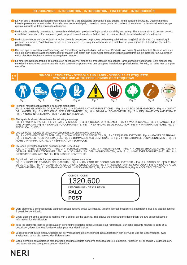
I simboli mostrati sopra hanno il seguente signifi cato: Fig. 1 > ABBIGLIAMENTO DA LAVORO - Fig. 2 > SCARPE ANTINFORTUNISTICHE - Fig. 3 > CASCO OBBLIGATORIO - Fig. 4 > GUANTI DA LAVORO, Fig. 5 > PERICOLO PER L’OPERATORE, Fig. 6 > DANNI AI COMPONENTI, Fig. 7 > INQUINAMENTO AMBIENTALE, Fig. 8 > NOTA INFORMATIVA, Fig. 9 > VERIFICA TECNICA.
The symbols shown above have the following meanings:Fig. 1 > WORK APPAREL - Fig. 2 > SAFETY SHOES - Fig. 3 > OBLIGATORY HELMET - Fig. 4 > WORK GLOVES, Fig. 5 > DANGER FOR THE OPERATOR, Fig. 6 > DAMAGE TO COMPONENTS, Fig. 7 > ENVIRONMENTAL POLLUTION, Fig. 8 > INFORMATIVE NOTE, Fig. 9 > TECHNICAL CHECK.
Les symboles indiqués ci-dessus correspondent aux signifi cations suivantes:Fig. 1 > VÊTEMENTS DE TRAVAIL - Fig. 2 > CHAUSSURES DE SÉCURITÉ - Fig. 3 > CASQUE OBLIGATOIRE - Fig. 4 > GANTS DE TRAVAIL, Fig. 5 > DANGER POUR L’OPÉRATEUR, Fig. 6 > DOMMAGES AUX COMPOSANTS, Fig. 7 > POLLUTION DE L’ENVIRONNEMENT, Fig. 8 > NOTE D’INFORMATION, Fig. 9 > VÉRIFICATION TECHNIQUE.
Die oben gezeigten Symbole haben folgende Bedeutung:Abb. 1 > ARBEITSKLEIDUNG - Abb. 2 > SCHUTZSCHUHE - Abb. 3 > HELMPFLICHT - Abb. 4 > ARBEITSHANDSCHUHE, Abb. 5 >GEFAHR FÜR DEN TECHNIKER, Abb. 6 > SCHÄDEN AN DEN KOMPONENTEN, Abb. 7 > UMWELTVERSCHMUTZUNG, Abb. 8 > INFORMATIONSBLATT, Abb. 9 > TECHNISCHE KONTROLLE.
Signifi cado de los símbolos que aparecen en las páginas anteriores: Fig. 1 > ROPA DE TRABAJO OBLIGATORIA - Fig. 2 > CALZADO DE SEGURIDAD OBLIGATORIO - Fig. 3 > CASCO DE SEGURIDAD OBLIGATORIO - Fig. 4 > GUANTES DE SEGURIDAD OBLIGATORIOS, Fig. 5 > PELIGRO PARA EL OPERADOR, Fig. 6 > DAÑOS A LOS COMPONENTES, Fig. 7 > CONTAMINACIÓN DEL MEDIO AMBIENTE, Fig. 8 > NOTA INFORMATIVA, Fig. 9 > CONTROL TÉCNICO.
La Neri spa è impegnata costantemente nella ricerca e progettazione di prodotti di alta qualità, lunga durata e sicurezza. Questo manuale intende presentare le metodiche di installazione corrette dei pali, ponendosi come guida nei confronti di installatori professionali. A tale scopo questo manuale va letto con molta attenzione.
Neri spa is constantly committed to research and design for products of high quality, durability and safety. This manual aims to present correct installation procedures for posts as a guide for professional installers. To this end the manual should be read with extreme attention.
Neri spa a toujours eu pour objectif la recherche et la conception de produits de haute qualité, offrant longévité et sécurité. Ce manuel, qui présente les modes d’installation corrects des candélabres, est un guide à l’adresse des installateurs professionnels. Il doit donc être lu très attentivement.
Die Neri spa ist konstant um Forschung und Entwicklung zeitbeständiger und sicherer Produkte von hoher Qualität bemüht. Dieses Handbuch stellt die korrekten Installationsmethoden für Masten und bietet sich gegenüber professionellen Installateuren als ein Ratgeber an. Deswegen sollte dies Handbuch sehr aufmerksam gelesen werden.
La empresa Neri spa trabaja de continuo en el estudio y el diseño de productos de alta calidad, larga duración y seguridad. Este manual con-tiene las instrucciones para instalar de modo correcto los postes y es una guía para instaladores profesionales. Por ello, se debe leer con gran atención.
Ogni elemento è contrassegnato da una etichetta adesiva posta sull’imballo. Vi sono riportati il codice e la descrizione, due dati basilari con cui è possibile identifi carlo.
Every element of the bollards is marked with a sticker on the packing. This shows the code and the description, the two essential items of information for identifi cation.
Tous les éléments bornes de dissuasion portent une étiquette adhésive placée sur l’emballage. Sur cette étiquette fi gurent le code et la description, deux données fondamentales pour leur identifi cation.
Jedes Poller ist durch einen Aufkleber auf der Verpackung gekennzeichnet. Darauf befi nden sich der Code und die Beschreibung, zwei Basisdaten, durch die man es identifi zieren kann.
Cada elemento para bolardos está marcado con una etiqueta adhesiva colocada sobre el embalaje. Aparecen allí el código y la descripción, dos datos básicos con que se pueden identifi car.
Fig. 1 Fig. 2 Fig. 3 Fig. 4 Fig. 5 Fig. 6 Fig. 7 Fig. 8 Fig. 9
INTRODUZIONE - INTRODUCTION - INTRODUCTION - EINLEITUNG - INTRODUCCIÓN
1° SIMBOLI / ETICHETTA - SYMBOLS AND LABEL- SYMBOLES ET ETIQUETTESYMBOLE UND AUFKLEBER - SÍMBOLOS Y ETIQUETAS

5
www.neri.biz
3°
A C
B
2°
I
GB
F
D
E
Gli elementi dei pali possono esere spediti e consegnati in vari modi: A) elementi singoli sfusi; B) elementi raggruppati su bancale in legno; C) elementi raggruppati in casse di legno su bancale.L’imballo dei singoli elementi può essere realizzato con cartone in vari strati, scatole di cartone, sacchetti di nylon.In ogni caso comunque al ricevimento della merce controllare che: 1) l’imballo sia integro; 2) la fornitura corrisponda all’ordine (vedi bolla di consegna); 3) non vi siano parti mancanti.
In caso di danni o parti mancanti, informare immediatamente e in modo dettagliato (e/o con foto) la Neri spa.
The elements of the posts can be shipped and delivered in various ways:A) loose single elements; B) elements packed together on wooden pallet; C) elements packed together in wooden crates on pallet.The single elements can be packed with several layers of cardboard, cardboard boxes and plastic bags.On receipt of the goods, always:1) check that packing is undamaged; 2) check that goods received correspond to order (consult delivery note); 3) check that there are no missing parts.
In case of damage or missing parts, immediately inform Neri spa, giving full details (and/or with photograph).
Les éléments des candélabres peuvent être expédiés et livrés de différentes façons:A) éléments seuls en vrac; B) éléments groupés sur palette en bois; C) éléments groupés dans des caisses en bois sur palette. L’emballage de chaque élément peut être réalisé dans des feuilles de carton, des boîtes en carton, des sacs en nylon.Dans tous les cas, s’assurer dès la réception de la marchandise que:1) l’emballage soit intact; 2) la fourniture corresponde à la commande (voir bulletin de livraison); 3) il ne manque aucune partie.
En cas de dommages ou de parties manquantes, en informer immédiatement d’une manière détaillée (et/ou avec photo) Neri spa.
Die Gusseisenelemente der Pfähle können auf verschiedene Weise transportiert und angeliefert werden:A) einzelne Elemente; B) gruppierte Elemente auf Palette; C) gruppierte Elemente in Holzkisten auf Palette. Die Verpackung der einzelnen Ele-mente kann aus Karton in mehreren Lagen bestehen, aus Kartonschachteln, aus Nylonsäcken. Jedenfalls muss man beim Wareneingang stets kontrollieren, dass:1) die Verpackung unversehrt ist; 2) die Lieferung der Bestellung entspricht (siehe Lieferschein); 3) keine Teile fehlen.
Bei Schäden oder fehlenden Teilen sofort und detailliert (u./o. mit Foto) die Neri spa informieren.
Los elementos de los postes se pueden expedir y entregar de varias formas:A) elementos individuales sueltos; B) elementos agrupados en palets de madera; C) elementos agrupados en cajas de madera sobre palets. El embalaje de cada elemento individualmente se puede realizar con cartones de varios estratos, cajas de cartón, sacos de nilón.De todos modos al recibir la mercancía controlen:1) que el embalaje esté íntegro; 2) que el suministro corresponda al pedido (vean albarán); 3) que no falten piezas.
En caso de daños o piezas que falten, infórmen a Neri spa de inmediato y con detalles (y/o con foto).
NOTE GENERALI ALLA CONSEGNA - DELIVERY INFORMATION - NOTES GENERALES POUR LA LIVRAISON ALLGEMEINE ANMERKUNGEN ZUR ANLIEFERUNG - NOTAS GENERALES A LA ENTREGA

6
I
GB
F
D
E
In base alle varie direttive in vigore nei vari paesi europei ed extraeuropei, nel luogo di lavoro devono essere rispettate determinate regole.Le indicazioni di sicurezza non hanno lo scopo di alterare o modifi care le direttive sopra menzionate; il loro unico scopo è quello di sottolinearle o amplifi carle. Queste prescrizioni di sicurezza sono indirizzate agli installatori professionali, i quali devono attentamente leggere e comprendere questo manuale di installazione.
ATTENZIONE, la non osservanza delle prescrizioni citate in questo manuale aumenta il rischio di incidenti.
Prima di effetuare qualsiasi operazione munirsi di: casco antiurto, guanti da lavoro, scarpe antifortunistiche, abbigliamento da lavoro ed eventualmente in base al peso dell’elemento da sollevare (consultare tabella pesi e codici) di un mezzo di sollevamento meccanico (gru, carrello, ecc.).
A variety of rules must be followed in workplaces, depending on the legislation applicable in different countries of Europe and elsewhere.The aim of the safety precautions illustrated here is not to replace or modify this applicable legislation, but solely to emphasize or reinforce it. These safety precautions are intended for professional installers, who must carefully read and understand this installation manual.
WARNING, failure to observe the prescriptions given in this manual will increase the risk of accidents.
Before carrying out any operations whatsoever installers must put on: safety helmets, work gloves, safety footwear and suitable working clothes. Depending on the weight of the element to be lifted (consult chart of weights and codes), mechanical lifting equipment (crane, forklift, etc) must be provided.
Conformément aux différentes directives en vigueur dans les pays européens et extra-européens, les lieux de travail sont soumis à des règles précises qui doivent être respectées. Ces indications de sécurité n’entendent ni modifi er ni altérer les directives susdites mais ont pour but de les souligner ou d’en étendre l’application. Ces prescriptions de sécurité s’adressent aux installateurs professionnels, qui devront lire attentivement ce manuel d’installation et en comprendre parfaitement le contenu.
ATTENTION - La non-observation des prescriptions indiquées dans ce manuel augmente le risque d’accidents.
Avant d’effectuer toute opération, s’équiper de: casque antichoc, gants de travail, chaussures de sécurité, habillement de travail et, éventuellement, en fonction du poids de l’élément à soulever (consulter le tableau des poids et codes) d’un appareil de levage mécanique (grue, chariot, etc.).
Auf Grundlage der verschiedenen in europäischen und außereuropäischen Ländern geltenden Vorschriften, müssen am Ort der Arbeit bestimmte Regeln eingehalten werden. Die Sicherheitsangaben haben nicht den Sinn, die o.a. Vorschriften zu verändern; ihr einziger Zweck ist es, sie zu unterstreichen oder zu erweitern. Diese Sicherheitsvorschriften wenden sich an professionelle Installateure, die dieses Installationshandbuch aufmerksam lesen und begreifen müssen.
ACHTUNG, Wenn die in diesem Handbuch angegebenen Vorschriften nicht eingehalten werden, erhöht sich die Unfallgefahr.
Vor der Durchführung von Arbeiten muss man sich eindecken mit: Schutzhelm, Arbeitshandschuhen, unfallsicheren Schuhen, Arbeitsbekleidung und evtl. aufgrund des Gewichtes des anzuhebenden Elements (nachsehen in der Tabelle der Gewichte und Codes) mit einem mechanischen Hebewerkzeug (Kran, Hubwagen usw.).
De acuerdo con las directivas en vigor en los distintos países europeos y no europeos, en el lugar de trabajo se deben respetar determinadas normas. Las normas de seguridad no tienen el objetivo de alterar ni modifi car dichas directivas; su único objetivo es el de ponerlas en evidencia o ampliarlas. Estas normas de seguridad se dirigen a los instaladores profesionales, quienes deben leer atentamente y comprender perfectamente este manual de instalación.
ATENCIÓN: el incumplimiento de las normas contenidas en este manual hace aumentar el riesgo de accidente.
Antes de iniciar cualquier tipo de trabajo, equiparse con: casco de seguridad, guantes de trabajo, calzado especial de trabajo, ropa de trabajo y, dependiendo del peso que se deba elevar (consultar la tabla de pesos y códigos), un medio mecánico de elevación adecuado (grúa, carretilla elevadora, etc.).
ATTENZIONE - CAUTIONATTENTION - ACHTUNG
ATENCIÓN
1191.0501191.0511295.0201295.0211310.6001310.6011310.7001310.701
403343517447620540720640
PALO-POST -CANDELABRE-MUST-POSTE
Kg h. cm.
3°
TABELLA CODICI ANIME PALI - CODE CHART FOR POST CORES - TABLEAU DES CODES DES AMES DE CANDELABRETABELLE DER CODES DER KERNMASTEN - TABLA DE CÓDIGOS DE ALMAS PARA POSTES
Peso e altezza massimi per tipo di anima - Maximum weight and height for core types - Poids et hauteur maximaux par type d’âmeGewicht und maximale Höhe je Seelentyp - Peso y altura máximos por tipo de alma
PRESCRIZIONI DI SICUREZZA - SAFETY PRECAUTIONSPRESCRIPTIONS DE SECURITE - SICHERHEITSVORSCHRIFTEN - NORMAS DE SEGURIDAD
1320.6001320.6011320.7001320.701 1351.7001351.7011351.8001351.801
620540720640720640820740
PALO-POST -CANDELABRE-MUST-POSTE
Kg h. cm.
32.830.7534975758781
556385839492
106104

7
www.neri.biz
C E
D
A B
4°
I
GB
F
D
E
Per il disimballo dei fasci di anime (in base al tipo di imballo omettere ciò che non serve) comportarsi nel seguente modo: 1) recintare la zona di lavoro; 2) dotarsi di una robusta corda (D) da legare in prossimità della parte terminale del fascio (Fig. A); 3) predisporre a terra una robusta stuoia per la protezione delle parti verniciate; 4) mettersi dietro la parte terminale del fascio e tagliare la centina (Fig. B) (ATTENZIONE - tale manovra può provocare il rotolamento di alcune anime del fascio verso terra); 5) lentamente sciogliere la corda (D) messa a protezione.
IMPORTANTE - non trascinare o rotolare le anime a terra, si possono danneggiare.
ATTENZIONE - La non osservanza delle prescrizioni citate sopra aumenta il rischio di incidenti.
IMPORTANTE - Non disperdere l’imballo nell’ambiente, potrebbe essere fonte di pericolo e inquinamento. Seguire le normali procedure di smaltimento dei rifi uti urbani (Fig. C) in conformità alle norme vigenti.
IMPORTANTE - L’anima è protetta da un’apposita pellicola antigraffi o (Fig. E), che non dovrà essere rimossa durante il disimballo ma solamente dopo l’installazione delle basi.
To unpack, proceed as follows (disregard instructions that do not apply to type of packing received): 1) Fence off the work area. 2) Tie a strong rope (F) round one end of the bundle of cores (Fig. A). 3) Lay a robust mat on ground to protect paintwork (Fig. A). 4) Stand behind the end of the bundle and cut strapping (Fig. B) (CAUTION: some cores of the bundle may roll onto the ground as a result of this operation). 5) carefully until the rope (D) fi tted for protective purposes.
IMPORTANT – do not drag or roll the cores on the ground as this may result in damage.
CAUTION – Failure to apply the precautions illustrated in this manual will increase the risk of accidents.
IMPORTANT – Do not dispose incorrectly of packaging materials, which could be a source of pollution and danger. Follow normal waste disposal procedures for urban wastes (Fig. C) in compliance with applicable legislation.
IMPORTANT - The core is protected by a special scratch-proof fi lm (Fig. E) which must not be removed during unpacking but only after the bases have been installed.
Pour le déballage des âmes en faisceaux (en fonction du type d’emballage, omettre les précisations inutiles) il est conseillé de suivre les indications suivantes:1) délimiter la zone de travail ; 2) se munir d’une corde robuste (D) à nouer à proximité de la partie terminale du faisceau (Fig. A) ; 3) étendre sur le sol une robuste natte afi n de protéger les parties peintes ; 4) se placer derrière la partie terminale du faisceau et couper la bande de cerclage (Fig. B) (ATTENTION – cette manoeuvre peut provoquer le roulement au sol de certaines âmes) ; 5) dénouer lentement la corde de protection (D).
IMPORTANT - Ne pas traîner ou faire rouler les âmes sur le sol afi n d’éviter tout dommage.
ATTENTION - La non-observation des prescriptions citées ci-dessus augmente le risque d’accidents.
IMPORTANT - Ne pas disperser l’emballage dans l’environnement, car il pourrait être source de danger ou pollution. Suivre les normales procédures d’élimination des déchets urbains (Fig. C) conformément aux normes en vigueur.
IMPORTANT - L’âme est protégée par une pellicule anti-rayures (Fig. E) prévue à cet usage, qui ne devra pas être retirée pendant le déballage, mais uniquement après l’installation des bases.
Beim Auspacken der Elemente (auf Basis des Verpackungstyps das weglassen, was nicht dienlich ist) muss man wie folgt vorgehen: 1) den Arbeitsbereich absperren; 2) ein robustes Tau besorgen (F), das man nahe am Ende um das Bündel bindet; 3) auf dem Boden eine robuste Matte zum Schutz der lackierten Teile ausbreiten (Abb. A); 4) sich hinter das Bündelende stellen und das Halteband durchtrennen (Abb. B) (ACHTUNG, es besteht Quetschgefahr); 5) langsam das Schutzseil lösen (D).
WICHTIG - weder die Mastkerne am Boden ziehen noch rollen, damit sie nicht beschädigt werden.
ACHTUNG - Die Nichtbeachtung dieser Anweisungen erhöht das Unfallrisiko.
WICHTIG - Die Verpackung nicht in der Umgebung liegen lassen, sie könnte eine Gefahrenquelle sein und die Umwelt verschmutzen. Folgen Sie den normalen Verfahren zur Beseitigung von städtischen Abfällen (Abb. C) entsprechend den geltenden Vorschriften.
WICHTIG - Das Mastrohr ist durch eine Kratzschutzfolie geschützt (Abb. E). Diese Folie darf beim Entfernen der Verpackung nicht entfernt werden, sondern erst nach der Montage der Unterteile.
Para desembalar los haces de almas (según el tipo de embalaje omitir lo que no sirve) y realizar las siguientes operaciones: 1) Delimitar la zona de trabajo; 2) Utilizar una maroma robusta (F) para ligar en la parte terminal del haz (Fig. A); 3) Poner en el suelo una estera gruesa para proteger las piezas pintadas; 4) Ponerse detrás de la parte fi nal del haz y cortar la tira envolvente (Fig. B) (ATENCIÓN: dicha maniobra puede provocar el rodamiento por tierra de algunas almas que escapen del haz); 5) desatar la cuerda (D) de protección lentamente.
IMPORTANTE – no arrastrar ni girar las almas mientras están en el suelo, podrían dañarse.
ATENCIÓN- El no observar las normas de seguridad citadas anteriormente implica aumentar el riesgo de accidentes.
IMPORTANTE- No dejen el embalaje tirado por ahí, podría resultar fuente de peligro o de contaminación. Sigan el procedimiento normal de retirada de la basura urbana (Fig. C) según las leyes vigentes.
IMPORTANTE - El alma está protegida por una película antirrayado (Fig. E), que sólo se debe eliminar después de haber instalado las bases y no tras el desembalaje.
IMPORTANTEIMPORTANTIMPORTANT
WICHTIGIMPORTANTE
DISIMBALLAGGIO ANIME PALI - POST CORES UNPACKING - DÉBALLAGE ÂMES CANDÉLABRES -AUSPACKEN MASTKERNE - DESEMBALAJE DE LAS ALMAS DE LOS POSTES
ATTENZIONE PERICOLOCAUTION : DANGERATTENTION DANGERACHTUNG GEFAHR
ATENCIÓN, PELIGRO

8
I
GB
F
D
E
IMPORTANTE - Dati per la messa in opera delle anime con muratura.
Lo schema illustrato in Fig. A, mostra un esempio tipico di anima con muratura. Tutte le anime con muratura sono dotate di: un bullone per la messa a terra; un’asola (A1) per l’entrata cavi elettrici, e di una seconda asola (A2) per l’installazione di una morsettiera.Per le misure dei diametri (Ø) e altezza (h) delle murature consultare la tabella informativa Fig. B. Il riferimento di quota zero è dato dalla quota (h) riportata nella tabella (B).
IMPORTANT - Data for installation of cement-in cores.
Fig. A shows a typical example of installation by cementing in. All cores to be installed in this way are complete with: an earthing bolt; a slot (A1) for entrance of electrical cables, and a second slot (A2) for installation of a terminal board. For diameters (Ø) and depths (h) of installation by cementing in consult the information chart in Fig. B. The zero position reference mark is given by position (h) shown in Table (B).
IMPORTANT – Données pour l’installation des âmes par scellement direct.
Le schéma illustré sur la Fig. A présente un typique exemple d’âme à sceller directement dans le sol. Toutes ces âmes sont dotées de: un boulon pour la mise à la terre; une boutonnière (A1) pour l’entrée des câbles électriques, et une seconde boutonnière (A2) pour l’installation d’un coffret de connexion.Pour les dimensions des diamètres (Ø) et hauteurs (h) des extrémités de scellement, consulter les tableaux informatifs Fig. B. Le repère de cote zéro est donné par la cote (h) reportée dans le tableau (B).
WICHTIG - Angaben über die Installation der Mastkerne mit Einmauerung.
Das in Abb. A illustrierte Schema zeigt ein typisches Beispiel für eine Seele mit Einmauerung. Alle einzumauernden Mastkerne sind ausgestattet mit: 1 Bolzen für die Erdung; 1 Langloch (A1) für das Einführen der Stromkabel und einem zweiten Langloch (A2) für die Installation des Klemmenbretts.In Bezug auf die Maße (Durchmesser Ø und Höhe h) siehe Informationstabelle Abb. B. Der Nullhöhenbezug wird vom in der Tabelle (B) angegebenen Wert (h) gegeben.
IMPORTANTE: Datos para la puesta en obra de las almas con mampostería.
El esquema de la Fig. A muestra un ejemplo típico de alma con mampostería. Todas las almas con mampostería están dotadas de: un perno de conexión a tierra; un ojal (A1) de entrada de los cables eléctricos y un segundo ojal (A2) para la instalación de una regleta.Los diámetros (Ø) y la altura (h) de la mampostería se indican en la tabla informativa Fig. B. La referencia de cota cero corresponde a la cota (h) indicada en la tabla (B).
TABELLE INFORMATIVEINFORMATION CHART
TABLEAUX INFORMATIFSINFORMATIONSTABELLEN
TABLA INFORMATIVA
PALO - POST- CANDELABRE PFAHL - POSTES Ø cm h. cm
1191.0501295.0201310.6001310.7001320.6001320.7001351.7001351.800
11,413,314,014,014,014,016,816,8
6070808080808080
B
5° SISTEMA DI FISSAGGIO CON MURATURA • FIXING SYSTEM – CEMENTING INSYSTEME D’ANCRAGE PAR SCELLEMENT DIRECT • BEFESTIGUNGSSYSTEM MIT EINMAUERN
SISTEMA DE FIJACIÓN CON MAMPOSTERÍA
A
A2
35
h
Ø
A1
Quota zeroZero position
Cote zéroHöhe NullCota cero

9
www.neri.biz
1191.0511295.0211310.6011310.7011320.6011320.7011351.7011351.801
F1F1F2F2F2F2F3F3
2,2
60°
ø 26,6 ø 9 ø 20
2,2
60°
ø 34,1 ø 9 ø 27,5
ø 24,6 ø 9
90°
ø 18
2,2
Ø246 mm
Ø266 mm
Ø341 mmØ275 mmØ90 mm
Ø200 mmØ90 mm
60°
60°
90
°
Ø180 mmØ90 mm
I
GB
F
D
E
IMPORTANTE - Dati per la messa in opera delle anime con fl angia.
Lo schema illustrato in Fig. C, mostra un esempio tipico di anima con fl angia. Tutte le anime con fl angia sono dotate di: un bullone per la messa a terra; un’asola (A1) per l’installazione di una morsettiera; quattro asole Ø 2,2 cm per tirafondi; un foro centrale Ø 9 cm per il passaggio dei cavi elettrici.Il simbolo ( ) indica la posizione dell’asola (A1). Il riferimento di quota zero è la base di appoggio della fl angia.
IMPORTANT - Data for installation of cores with fl ange.
Fig. C shows a typical example of installation with a fl ange. All cores to be installed in this way are complete with: an earthing bolt; a slot (A1) for installation of a terminal board; four slots Ø 2,2 cm for anchor bolts; a central hole Ø 9 cm for entry of the electrical cables.The ( ) shows the position of the slot (A1). The zero position reference mark is the supporting base of the fl ange.
IMPORTANT - Données pour l’installation des âmes avec bride.
Le schéma illustré sur la Fig. C présente un typique exemple d’âme avec semelle de fi xation. Toutes les âmes avec semelle sont dotées de:un boulon pour la mise à la terre; une fente (A1) pour l’installation d’un bornier ; quatre fentes Ø 2,2 cm pour tire-fond ; un trou central Ø 9 cm pour le passage des câbles électriques.Le symbole ( ) indique la position de la fente (A1). Le repère de cote zéro est la base d’appui de la bride.
Angaben für die Montage der Mastrohre mit Flansch.
Die Skizze von Abb. C zeigt ein typisches Beispiel eines Mastrohrs mit Flansch. Alle Mastrohre mit Flansch verfügen über Folgendes: eine Mutterschraube für die Erdung; ein Langloch (A1) für die Installation einer Klemmenleiste; vier Langlöcher Ø 2,2 cm für Ankerbolzen; ein mittleres Loch Ø 9 cm für die Durchführung der Stromkabel.Das Symbol ( ) gibt die Position des Langlochs (A1) an. Der Bezugspunkt für die Höhe Null ist die Aufl agefl äche des Flansches.
IMPORTANTE: Datos para la puesta en obra de las almas con brida.
El esquema de la Fig. C muestra un ejemplo típico de alma con brida. Todas las almas con brida están dotadas de: un perno para la conexión a tierra, un ojal (A1) para la instalación de la regleta, cuatro ojales Ø 2,2 cm para tirafondos y un orifi cio central Ø 9 cm para la entrada de los cables eléctricos.El símbolo ( ) indica la posición del ojal (A1). La referencia de cota cero se corresponde con la base de apoyo de la brida.
PALO - FLANGIAPOST - FLANGE
CANDELABRE-SEMELLEPFAHL - FLANSCHPOSTES - BRIDA
6° SISTEMA DI FISSAGGIO CON FLANGIA • FIXING SYSTEM – FLANGE • SYSTEME D’ANCRAGE AVEC SEMELLE DE FIXATION • BEFESTIGUNGSSYSTEM – FLANSCH - SISTEMA DE FIJACIÓN CON BRIDA
C
A1
Ø
Quota zeroZero position
Cote zéroHöhe NullCota cero
F2F2
F3F3
F1F1

10
A B C D E
I
GB
F
D
E
7°
Per applicare la guaina protettiva termorestringente sulle anime con muratura eseguire le seguenti operazioni:
ATTENZIONE - Pericolo di schiacciamento.
1) recintare la zona di lavoro;2) predisporre due robusti cavaletti (Fig. A) da posizionare ben livellati e stabili, dotati di sponde più alte rispetto al piano d’appoggio onde evitare
la caduta accidentale a terra dell’anima; una bombola di gas propano completa di torcia (Fig. B); una guaina protettiva della giusta misura daapplicare sull’anima (Fig. C);
3) pulire accuratamente con uno straccio umido la superfi ce in cui andrà applicata la guaina protettiva (Fig. D);4) strappare la pellicola protettiva interna alla guaina (Fig. E) e inserire la guaina sull’anima;
To apply the protective heat-shrink sheath to cores to be cemented in, proceed as follows:
CAUTION - Crushing danger.
1) Fence off the work area.2) Prepare two strong trestles (Fig. A) to be placed in a stable, level position, with sides higher than the crosspieces to prevent the accidental fall of the core;
a canister of propane gas complete with blow torch (Fig. B); a protective sheath of the correct size to be applied to the core (Fig. C).3) Thoroughly clean the surface to which the sheath is to be applied with a damp rag (Fig. D).4) Tear away the protective fi lm inside the sheath (Fig. E) and insert sheath on core.
Pour appliquer la gaine de protection thermorétrécissante sur les âmes à scellement direct, effectuer les opérations suivantes:
ATTENTION - Risque d’écrasement.
1) délimiter la zone de travail;2) installer deux chevalets robustes (Fig. A) en position horizontale et stable, dotés de rebords plus élevés par rapport au plan d’appui pour éviter toute chute
de l’âme sur le sol; une bouteille de gaz propane équipée de torche (Fig. B); une gaine de protection de taille appropriée à appliquer sur l’âme (Fig. C);3) nettoyer soigneusement à l’aide d’un chiffon humide la surface sur laquelle la gaine de protection devra être appliquée (Fig. D);4) arracher le fi lm de protection interne de la gaine (Fig. E) et introduire la gaine sur l’âme.
Um den durch Wärme schrumpfbaren Schutzmantel auf einzumauernde Seelen aufzubringen, führt man folgende Operationen durch:
ACHTUNG – Quetschgefahr.
1) Arbeitsbereich absperren.2) Zwei robuste Böcke (Abb. A), deren Pfosten über die Aufl agesprossen hinausragen, wodurch ein Herunterfallen der Seelen vermieden wird, stabil und ausbilanziert
aufstellen; eine Propangasbombe mit Brenner (Abb. B) bereit halten; außerdem eine gut abgemessene Schutzfolie zur Aufbringung auf die Seele (Abb. C).3) Mit einem feuchten Lappen die zu behandelnde Oberfl äche akkurat säubern (Abb. D) .4) Den internen Schutzfi lm des Schutzmantels (Abb. E) entfernen und den Schutzmantel über die Seele ziehen.
Para aplicar la funda protectora termorresistente sobre las almas con mampostería, realizar las operaciones siguientes:
ATENCIÓN: Peligro de aplastamiento.
1) Delimitar la zona de trabajo.2) Preparar dos caballetes robustos (Fig. A), estables y bien nivelados cuyos bordes superen la superfi cie de apoyo para evitar la caída accidental a
tierra del alma, una bombona de gas propano con soplete (Fig. B) y una funda protectora del tamaño adecuado para aplicarla sobre el alma (Fig. C).3) Limpiar a fondo la superfi cie en que se aplicará la funda protectora, con un trapo húmedo (Fig. D).4) Extraer la película protectora del interior de la funda (Fig. E) y colocar la funda sobre el alma.
ATTENZIONE PERICOLOCAUTION : DANGERATTENTION DANGERACHTUNG GEFAHR
ATENCIÓN, PELIGRO
Nota: sulle anime con fl angia non và applicata la guaina protettiva
Note: protective sheaths are not fi tted on cores with fl ange
Note: la gaine de protection ne doit pas être appliquée sur les âmes avec semelle.
Anmerkung: bei den Seelen mit Flansch wird kein Schutzmantel aufgebracht.
Nota: en las almas con brida no se aplica la funda protectora.
APPLICAZIONE GUAINA PROTETTIVA - FITTING OF PROTECTIVE SHEATH - APPLICATION DE LA GAINE DEPROTECTION - AUFBRINGUNG DES SCHUTZMANTELS - APLICACIÓN DE UNA FUNDA PROTECTORA
11
www.neri.biz
F
I
G
L
H
M N
I
GB
F
D
E
ATTENZIONE PERICOLOCAUTION : DANGERATTENTION DANGERACHTUNG GEFAHR
ATENCIÓN, PELIGRO
7°
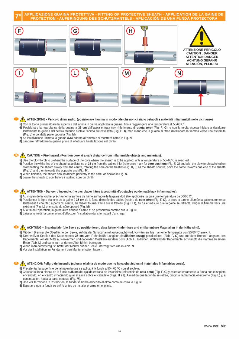
ATTENZIONE - Pericolo di incendio. (posizionare l’anima in modo tale che non ci siano ostacoli e materiali infi ammabili nelle vicinanze).
5) Con la torcia preriscaldare la superfi ce dell’anima in cui và applicata la guaina, fi no a raggiungere una temperatura di 50/60 C°.6) Posizionare la riga bianca della guaina a 35 cm dall’asola entrata cavi (riferimento di quota zero) (Fig. F, G), e con la torcia accesa iniziare a riscaldare
lentamente la guaina dal centro facendo ruotale l’anima sul cavalletto (Fig. H, I), man mano che la guaina si ritrae direzionare la fi amma verso una estremità (Fig. L) e poi dalla parte opposta (Fig. M).
7) Ad installazione ultimata la guaina avrà aderito all’anima e si mostrerà come in Fig. N8) Lasciare raffreddare la guaina prima di effettuare l’installazione nel plinto.
CAUTION – Fire hazard. (Position core at a safe distance from infl ammable objects and materials).
5) Use the blow torch to preheat the surface of the core where the sheath is to be applied, until a temperature of 50–60°C is reached.6) Position the white line of the sheath at a distance of 35 cm from the cables inlet (reference mark for zero position) (Fig. F, G) and with the blow torch switched on
start heating the sheath slowly from the centre, rotating the core on the trestles (Fig. H, I); as the sheath shrinks, point the fl ame towards one end of the sheath (Fig. L) and then towards the opposite end (Fig. M).
7) When fi nished, the sheath should adhere perfectly to the core, as shown in Fig. N.8) Leave the sheath to cool before installing core on plinth.
ATTENTION - Danger d’incendie. (ne pas placer l’âme à proximité d’obstacles ou de matériaux infl ammables).
5) Au moyen de la torche, préchauffer la surface de l’âme sur laquelle la gaine doit être appliquée jusqu’à une température de 50/60 C°.6) Positionner la ligne blanche de la gaine à 35 cm de la fente d’entrée des câbles (repère de cote zéro) (Fig. F, G), et avec la torche allumée la gaine commence
lentement à chauffer, à partir du centre, en faisant tourner l’âme sur le tréteau (Fig. H, I), au fur et mesure que la gaine se rétracte, diriger la fl amme vers une extrémité (Fig. L) et ensuite du côté opposé (Fig. M).
7) À la fi n de l’opération, la gaine aura adhéré à l’âme et se présentera comme sur la Fig. N.8) Laisser refroidir la gaine avant d’effectuer l’installation dans le massif d’ancrage.
ACHTUNG – Brandgefahr (die Seele so positionieren, dass keine Hindernisse und entfl ammbare Materialien in der Nähe sind).
5) Mit dem Brenner die Oberfl äche der Seele, auf die der Schutzmantel aufgebracht wird, vorwärmen, bis man eine Temperatur von 50/60 °C erreicht.6) Den weißen Streifen des Kabelmantes 35 cm vom Rohreinführ-Langloch (Nullhöhenbezug) positionieren (Abb. F, G) und mit dem Brenner langsam den
Kabelmantel von der Mitte aus erwärmen und dabei den Mastkern auf dem Bock (Abb. H, I) drehen. Während der Kabelmantel schrumpft, die Flamme zu einem Ende (Abb. L) und dann zum anderen (Abb. M) hin bewegen.
7) Wenn man damit fertig ist, haftet der Mantel auf der Seele und zeigt sich wie in Abb. N.8) Vor der Installation im Fundament den Mantel erkalten lassen.
ATENCIÓN: Peligro de incendio (colocar el alma de modo que no haya obstáculos ni materiales infl amables cerca).
5) Precalentar la superfi cie del alma en la que se aplicará la funda a 50 - 60 ºC con el soplete.6) Colocar la línea blanca de la funda a 35 cm del ojal de entrada de los cables (referencia de cota cero) (Fig. F, G) y calentar lentamente la funda con el soplete
encendido, en el centro y haciendo girar el alma sobre el caballete (Figs. H e I). A medida que la funda se retrae, dirigir la llama hacia el extremo (Fig. L) y, a continuación. hacia la parte opuesta (Fig. M).
7) Una vez terminada la instalación, la funda se habrá adherido al alma como muestra la Fig. N.8) Esperar a que la funda se enfríe antes de instalar el alma en el plinto.
APPLICAZIONE GUAINA PROTETTIVA - FITTING OF PROTECTIVE SHEATH - APPLICATION DE LA GAINE DEPROTECTION - AUFBRINGUNG DES SCHUTZMANTELS - APLICACIÓN DE UNA FUNDA PROTECTORA

12
HB
P
L
I
GB
F
D
E
A B
G
P
P
G
T
I
GB
F
D
E
Per realizzare il plinto devono essere forniti dal direttore dei lavori i seguenti dati: dimensioni (L,P,H,); dosaggio del calcestruzzo; ferri per l’armatura interna; dimensione e tipo dei tirafondi (non forniti).
For the construction of the plinth the clerk of works must provide the following information: dimensions (L, P, H); concrete mix proportions; steel bars for internal reinforcement; dimensions and type of anchor bolts (not supplied).
Pour la réalisation du massif d’ancrage, le directeur des travaux doit fournir les données suivantes: dimensions (L, P, H); dosage du béton; fers à béton; dimension et type de tire-fond (non fournis).
Zur Anfertigung des Fundamentsockels müssen vom Verantwortlichen für die Arbeiten die folgenden Daten geliefert werden: Dimensionen (H, T, B); Dosierung der Zementmischung; Armierungseisen; Dimensionen und Typ der Bodenbefestigungseisendübel (werden nicht geliefert).
Para realizar el plinto o base, el director de los trabajos debe proporcionar los datos siguientes: dimensiones (L, P, H); dosis de hormigón, hierros para el armado interno; dimensiones y tipo de los tirafondos (no suministrados de fábrica).
1) Il disegno di Fig. A, mostra la sezione di un plinto per pali con muratura. Nel centro del plinto và realizzato un foro con dimensioni (B,Ø) idonee all’inserimento dell’anima del palo, la tabella a pag. 8 riporta tutte le dimensioni (altezza e diametro) delle anime pali con muratura. Il diametro (Ø) del foro ricavato nel plinto dovrà essere circa 10 cm superiore al diametro della muratura dell’anima da installare. Predisporre un tubo fl essibile (G, diametro interno cm 2) e un altro (P, diametro interno cm 5) in PVC, per il passaggio dei cavi elettrici dal pozzetto di derivazione all’anima. 2) Il disegno di Fig. B, mostra la sezione di un plinto per pali con fl angia. Nel centro del plinto vànno annegati i tirafondi (T), i disegni a pag. 9 e 14 riportano tutte le informazioni (fori, diametri, interassi) per il posizionamento. I tirafondi (T) devono essere posizionati 5 cm più alti rispetto al piano del plinto, e devono avere la parte sporgente fi lettata. Predisporre un tubo fl essibile (G, diametro interno cm 5) in PVC, per il passaggio dei cavi elettrici dal pozzetto di derivazione all’anima, da posizionare al centro fra i tirafondi e un altro (P, diametro interno cm 2) per il cavo di massa.
1) The drawing in Fig. A shows the cross section of a plinth for cores to be cemented in. At the centre of the plinth there should be a hole (dimensions B,Ø) suitable for insertion of the core. The chart on page 8 shows the relative dimensions (height and diameter) for all cores for cementing in. The holein the plinth should have diameter (Ø) at least 10 cm greater than the diameter of the base of the core to be installed. Prepare a fl exible PVC tube (G, inside diameter 2 cm) and a second one (P, inside diameter 5 cm) for the passage of the electrical cables from the branch box to the core. 2) The drawing in Fig. B shows the cross section of a plinth for cores with fl anges. Anchor bolts (T) must be sunk into the centre of the plinth; the drawings on pages 9 and 14 give all the relative information (holes, diameters, centre distances) for positioning of the anchor bolts. The anchor bolts (T) must be positioned 5 cm higher than the plinth level, and the protruding sections must be threaded. Prepare a fl exible PVC tube (G, inside diameter 5 cm) for the passage of electrical cables from the branch box to the core, to be positioned at the centre between the anchor bolts, and prepare a second tube (P, inside diameter 2 cm) for the earth cable.
1) Le dessin de la Fig. A, montre la section d’un plinthe pour des candélabres à scellement direct. Le trou à réaliser au centre du plinthe doit avoir des dimensions (B,Ø) appropriées pour l’introduction de l’âme du candélabre, le tableau à page 8 reporte toutes les dimensions (hauteur et diamètre) des âmes des candélabres à scellement direct. Le diamètre (Ø) du trou pratiqué dans le plinthe devra être d’environ 10 cm supérieur au diamètre du scellement de l’âme à installer. Prévoir un tube fl exible (G, diamètre interne 2 cm) et un autre (P, diamètre interne 5 cm) en PVC, pour le passage des câbles électriques de la chambre de dérivation à l’âme. 2) Le dessin de la Fig. B, montre la section d’un plinthe pour des candélabres avec bride. Le trou à réaliser au centre du plinthe doit être profond 10 cm et avoir un diamètre approprié pour l’introduction de la Bride (voir dessin page 9) UNIQUEMENT pour lescandélabres du tableau (Fig. B). Les tire-fond (T) doivent être noyés toujours au centre du plinthe, les dessins aux pages 9 et 14 reportent toutes les informations (trous, diamètres, entraxes) pour le positionnement correct. Les tire-fond (T) doivent être positionnés 5 cm plus hauts par rapport au niveau du plinthe et leur partie saillante doit être fi letée. Prévoir un tube fl exible (G, diamètre interne 5 cm) en PVC, pour le passage des câbles électriques de la chambre de dérivation à l’âme, à positionner au centre entre les tire-fond et un autre (P, diamètre interne 2 cm) pour le câble de masse.
1) Die Zeichnung von Abb. A zeigt den Querschnitt eines Sockels für einzumauernde Masten. Der Sockel muss im Zentrum mit einem Loch mit den Abmessungen (B,Ø) versehen werden, in das das Mastrohr eingesetzt werden kann. Die Tabelle auf S. 8 enthält alle Maßangaben (Höhe und Durchmesser) der einzumauendern Mastrohre. Der Durchmesser (Ø) des Lochs im Sockel muss ca. 10 größer als der Einmauerungsdurchmesser des zu montierenden Mastrohrs sein. Ein fl exibles Installationsrohr (G, Innendurchmesser 2 cm) und ein weiteres Installationsrohr (P, Durchmesser 5 cm) aus PVC für die Verlegung der Stromkabel vom Abzweigschacht zum Mastrohr vorsehen. 2) Die Zeichnung von Abb. B zeigt den Querschnitt eines Sockels für Masten mit Flansch. Im Zentrum des Sockels müssen die Ankerbolzen (T) eingelassen werden. Die Zeichnungen auf S. 9 und 14 enthalten alle für die Positionierung erforderlichen Informationen (Löcher, Durchmesser, Achsabstände). Der gewindete Teil der Ankerbolzen (T) muss 5 cm aus der Oberseite des Sockels herausragen. Ein fl exibles Installationsrohr (G, Innendurchmesser 5 cm) aus PVC für die Verlegung der Stromkabel vom Abzweigschacht zum Mastrohr im Zentrum der Ankerbolzen anordnen. Ein weiteres Installationsrohr (P, Innendurchmesser 2 cm) für das Erdungskabel vorsehen.
1) El dibujo de la Fig. A muestra la sección de un plinto para postes con mampostería. En el centro del plinto se debe realizar un orifi cio de dimensiones adecuadas (B,Ø) para introducir el alma del poste. En la tabla de la pág. 8 se indican todas las medidas (altura y diámetro) de las almas de postes con mampostería. El diámetro (Ø) del orifi cio realizado en el plinto debe ser unos 10 cm más grande que el diámetro de la mampostería del ánima que se ha de instalar. Colocar un tubo fl exible (G, diámetro interno 2 cm) y un tubo (P, diámetro interno 5 cm) de PVC para hacer pasar los cables desde la caja de derivación al alma. 2) El dibujo de la Fig. B, muestra la sección de un plinto para postes con brida. Sumergir los tirafondos (T) en el plinto. Consultar las fi guras de las págs. 9 y 14 para conocer las medidas de instalación (orifi cios, diámetros y distancias entre ejes). El extremo roscado de los tirafondos (T) debe sobresalir 5 cm por encima de la superfi cie del plinto. Colocar un tubo fl exible (G, diámetro interno cm 5) de PVC en el centro de los tirafondos para hacer pasar los cables eléctricos desde la caja de derivación al alma en el centro de los tirafondos y un segundo tubo (P, diámetro interno cm 2) para hacer pasar el cable de masa.
8° PLINTO DI FONDAZIONE - CROSS SECTION - MASSIF D’ANCRAGEFUNDAMENTSOCKEL - PLINTO DE CIMENTACIÓN

13
www.neri.biz
A B C
I
GB
F
D
E
ATTENZION - CAUTIONATTENTION - ACHTUNG
ATENCIÓN
9°
ATTENZIONE - Recintare la zona di lavoro. Se si utilizza un braccio meccanico per il sollevamento dell’anima (vedi tabella pesi e altezze anime a pag. 6) attuare tutte le prescrizioni sull’uso in sicurezza di tale braccio. ATTENZIONE - Pericolo di oscillazione.
Per imbragare l’anima eseguire le istruzioni sotto elencate: 1) Munirsi di un cavo in acciaio senza ganci con portata non inferiore a 250 Kg e di lunghezza idonea (vedi altezza anima a pag. 6). 2) Inserire il cavo all’interno dell’asola sede morsettiera (Fig. B). 3) Eseguire un nodo all’estremità inferiore del cavo di acciaio (Fig. B). 4) Fare un cappio all’estremità superiore del cavo e fi ssare il tutto con due morsetti per cavi metallici (Fig. C).
IMPORTANTE - Interporre fra il cavo e l’anima degli strati di cartone per proteggere la verniciatura.
5) Agganciare il cappio al gancio del braccio meccanico e sollevare lentamente l’anima.
CAUTION - Fence off the work area. If a crane is used to lift the core (see chart with weights on page 6) take all precautions for the safe use of this equipment. CAUTION: Danger of swinging objects.
To secure the core to be lifted follow these instructions: 1) Procure a steel cable without hooks, with a lifting capacity of at least 250 kg and of a suitable length (see core heights on page 6). 2) Insert the cable through the terminal board seat slot (Fig. B). 3) Make a knot at the lower end of the steel cable (Fig. B). 4) Make a loop at the upper end of the cable and secure it with two metal cable U-clamps (Fig. C).
IMPORTANT - Place layers of cardboard between the core and the cable to protect the paintwork.
5) Attach the loop to the crane hook and slowly lift the core.
ATTENTION - Délimiter la zone de travail. Dans le cas d’utilisation d’un bras mécanique pour le levage de l’âme (voir tableau poids et hauteursdes âmes à pag. 6) respecter toutes les prescriptions de sécurité concernant l’utilisation de ces appareils. ATTENTION, risque d’oscillations.
Pour élinguer l’âme, suivre les instructions suivantes: 1) S’équiper d’un câble en acier sans crochets d’une portée non inférieure à 250 kg et de longueur appropriée (voir hauteur des âmes à pag. 6). 2) Introduire le câble à l’intérieur de la fente (Fig. B). 3) Réaliser un noeud à l’extrémité inférieure du câble en acier (Fig. B). 4) Faire un noeud coulant à l’extrémité supérieure du câble et fi xer le tout avec deux bornes pour câbles métalliques (Fig. C).
IMPORTANT - Il est nécessaire de placer des feuilles de carton entre le câble et l’âme, afi n de protéger la peinture.
5) Accrocher le noeud coulant au crochet du bras mécanique et soulevet lentement l’âme.
ACHTUNG - Den Arbeitsbereich absperren. Wird zum Anheben des Mastrohrs ein Mobilkran verwendet (siehe die Tabelle mit den Angaben zum Gewicht und zur Höhe der Mastrohre auf S. 6) alle Vorschriften in Bezug auf den sicheren Gebrauch dieses Mobilkrans beachten. ACHTUNG: Die Last kann ins Schwingen geraten.
Zum Anschlagen des Mastrohrs die nachstehenden Anweisungen befolgen: 1) Ein Stahlseil ohne Haken verwenden, dessen Tragfähigkeit mindestens 250 kg beträgt und das eine geeignete Länge hat (siehe die Höhe des Mastrohrs auf S. 6). 2) Das Seil in das Langloch für die Klemmenleiste (Fig. B) einführen. 3) Das untere Ende des Stahlseils mit einem Knoten versehen (Abb. B). 4) Am anderen Ende des Stahlseils eine Schlaufe bilden und mit zwei Seilklemmen blockieren (Abb. C).
WICHTIG Zwischen das Stahlseil und das Mastrohr Kartonstreifen einfügen, um die Lackierung zu schützen..
5) Die Schlaufe in den Haken des Mobilkrans einhängen und das Mastrohr langsam anheben.
ATENCIÓN - Delimitar la zona de trabajo. Si se utiliza un brazo mecánico para elevar el alma (véase la tabla de pesos y alturas en la pág. 6), respetar las normas de uso para utilizar el brazo de modo seguro. ATENCIÓN: peligro de oscilación.
Para eslingar el alma, respetar las siguientes instrucciones: 1) Utilizar un cable de acero sin ganchos con capacidad para soportar cargas de más de 250 kg y que posea una longitud adecuada (véase la altura del alma en la pág. 6). 2) Introducir el cable dentro del ojal situado en la regleta (Fig. B). 3) Realizar un nudo en el extremo inferior del cable de acero (Fig. B). 4) Realizar un lazo en el extremo superior del cable y fi jar el tubo con dos anclajes para cables metálicos (Fig. C).
IMPORTANTE: Colocar entre el cable y el alma varios estratos de cartón para proteger la pintura.
5) Enganchar el lazo al gancho del brazo mecánico y levantar lentamente el alma.
IMBRACATURA PALO - POST SLINGING - ÉLINGAGE CANDÉLABRE - ANSCHLAG LICHTMAST - ESLINGADO DEL POSTE
14
A
I
GB
F
D
E
10°
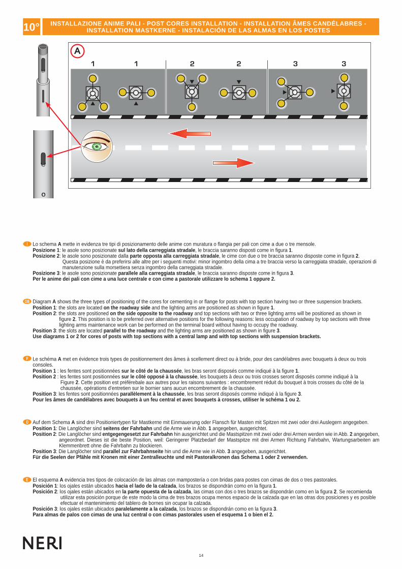
Lo schema A mette in evidenza tre tipi di posizionamento delle anime con muratura o fl angia per pali con cime a due o tre mensole.Posizione 1: le asole sono posizionate sul lato della carreggiata stradale, le braccia saranno disposti come in fi gura 1.Posizione 2: le asole sono posizionate dalla parte opposta alla carreggiata stradale, le cime con due o tre braccia saranno disposte come in fi gura 2.
Questa posizione è da preferirsi alle altre per i seguenti motivi: minor ingombro della cima a tre braccia verso la carreggiata stradale, operazioni di manutenzione sulla morsettiera senza ingombro della carreggiata stradale.
Posizione 3: le asole sono posizionate parallele alla carreggiata stradale, le braccia saranno disposte come in fi gura 3.Per le anime dei pali con cime a una luce centrale e con cime a pastorale utilizzare lo schema 1 oppure 2.
Diagram A shows the three types of positioning of the cores for cementing in or fl ange for posts with top section having two or three suspension brackets.Position 1: the slots are located on the roadway side and the lighting arms are positioned as shown in fi gure 1.Position 2: the slots are positioned on the side opposite to the roadway and top sections with two or three lighting arms will be positioned as shown in
fi gure 2. This position is to be preferred over alternative positions for the following reasons: less occupation of roadway by top sections with three lighting arms maintenance work can be performed on the terminal board without having to occupy the roadway.
Position 3: the slots are located parallel to the roadway and the lighting arms are positioned as shown in fi gure 3.Use diagrams 1 or 2 for cores of posts with top sections with a central lamp and with top sections with suspension brackets.
Le schéma A met en évidence trois types de positionnement des âmes à scellement direct ou à bride, pour des candélabres avec bouquets à deux ou trois consoles.Position 1 : les fentes sont positionnées sur le côté de la chaussée, les bras seront disposés comme indiqué à la fi gure 1.Position 2 : les fentes sont positionnées sur le côté opposé à la chaussée, les bouquets à deux ou trois crosses seront disposés comme indiqué à la
Figure 2. Cette position est préférebale aux autres pour les raisons suivantes : encombrement réduit du bouquet à trois crosses du côté de la chaussée, opérations d’entretien sur le bornier sans aucun encombrement de la chaussée.
Position 3: les fentes sont positionnées parallèlement à la chaussée, les bras seront disposés comme indiqué à la fi gure 3.Pour les âmes de candélabres avec bouquets à un feu central et avec bouquets à crosses, utiliser le schéma 1 ou 2.
Auf dem Schema A sind drei Positioniertypen für Mastkerne mit Einmauerung oder Flansch für Masten mit Spitzen mit zwei oder drei Auslegern angegeben.Position 1: Die Langlöcher sind seitens der Fahrbahn und die Arme wie in Abb. 1 angegeben, ausgerichtet.Position 2: Die Langlöcher sind entgegengesetzt zur Fahrbahn hin ausgerichtet und die Mastspitzen mit zwei oder drei Armen werden wie in Abb. 2 angegeben,
angeordnet. Dieses ist die beste Position, weil: Geringerer Platzbedarf der Mastspitze mit drei Armen Richtung Fahrbahn, Wartungsarbeiten am Klemmenbrett ohne die Fahrbahn zu blockieren.
Position 3: Die Langlöcher sind parallel zur Fahrbahnseite hin und die Arme wie in Abb. 3 angegeben, ausgerichtet.Für die Seelen der Pfähle mit Kronen mit einer Zentralleuchte und mit Pastoralkronen das Schema 1 oder 2 verwenden.
El esquema A evidencia tres tipos de colocación de las almas con mampostería o con bridas para postes con cimas de dos o tres pastorales.Posición 1: los ojales están ubicados hacia el lado de la calzada, los brazos se dispondrán como en la fi gura 1.Posición 2: los ojales están ubicados en la parte opuesta de la calzada, las cimas con dos o tres brazos se dispondrán como en la fi gura 2. Se recomienda
utilizar esta posición porque de este modo la cima de tres brazos ocupa menos espacio de la calzada que en las otras dos posiciones y es posible efectuar el mantenimiento del tablero de bornes sin ocupar la calzada.
Posición 3: los ojales están ubicados paralelamente a la calzada, los brazos se dispondrán como en la fi gura 3.Para almas de palos con cimas de una luz central o con cimas pastorales usen el esquema 1 o bien el 2.
INSTALLAZIONE ANIME PALI - POST CORES INSTALLATION - INSTALLATION ÂMES CANDÉLABRES - INSTALLATION MASTKERNE - INSTALACIÓN DE LAS ALMAS EN LOS POSTES
15
www.neri.biz
B C
I
GB
F
D
E
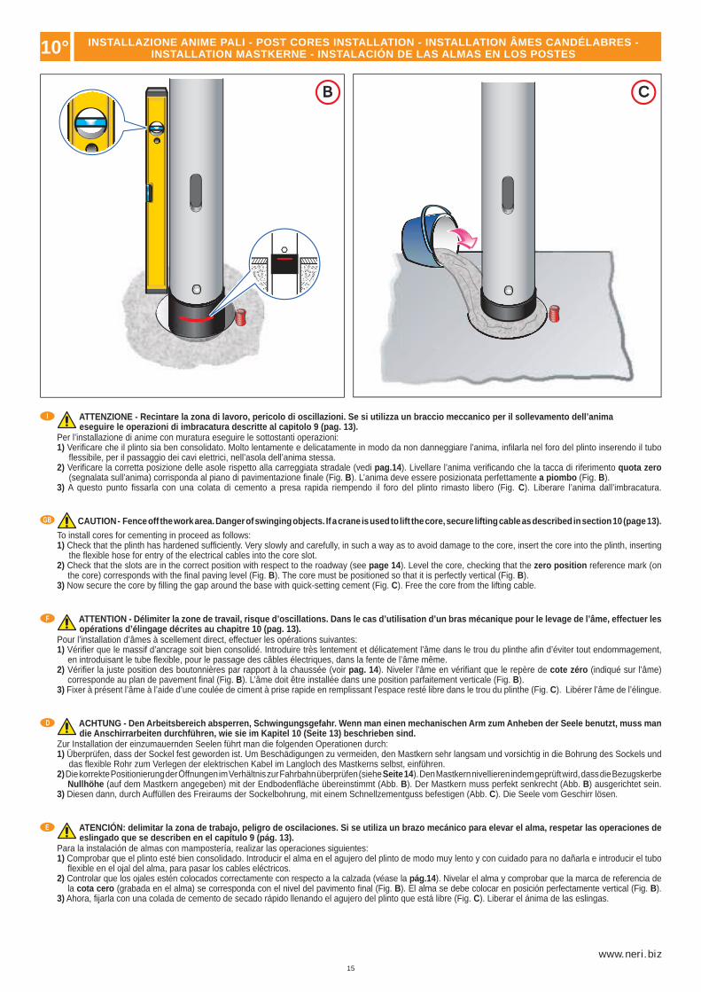
ATTENZIONE - Recintare la zona di lavoro, pericolo di oscillazioni. Se si utilizza un braccio meccanico per il sollevamento dell’animaeseguire le operazioni di imbracatura descritte al capitolo 9 (pag. 13).
Per l’installazione di anime con muratura eseguire le sottostanti operazioni:1) Verifi care che il plinto sia ben consolidato. Molto lentamente e delicatamente in modo da non danneggiare l’anima, infi larla nel foro del plinto inserendo il tubo
fl essibile, per il passaggio dei cavi elettrici, nell’asola dell’anima stessa.2) Verifi care la corretta posizione delle asole rispetto alla carreggiata stradale (vedi pag.14). Livellare l’anima verifi cando che la tacca di riferimento quota zero
(segnalata sull’anima) corrisponda al piano di pavimentazione fi nale (Fig. B). L’anima deve essere posizionata perfettamente a piombo (Fig. B).3) A questo punto fi ssarla con una colata di cemento a presa rapida riempendo il foro del plinto rimasto libero (Fig. C). Liberare l’anima dall’imbracatura.
CAUTION - Fence off the work area. Danger of swinging objects. If a crane is used to lift the core, secure lifting cable as described in section 10 (page 13).
To install cores for cementing in proceed as follows:1) Check that the plinth has hardened suffi ciently. Very slowly and carefully, in such a way as to avoid damage to the core, insert the core into the plinth, inserting
the fl exible hose for entry of the electrical cables into the core slot.2) Check that the slots are in the correct position with respect to the roadway (see page 14). Level the core, checking that the zero position reference mark (on
the core) corresponds with the fi nal paving level (Fig. B). The core must be positioned so that it is perfectly vertical (Fig. B).3) Now secure the core by fi lling the gap around the base with quick-setting cement (Fig. C). Free the core from the lifting cable.
ATTENTION - Délimiter la zone de travail, risque d’oscillations. Dans le cas d’utilisation d’un bras mécanique pour le levage de l’âme, effectuer les opérations d’élingage décrites au chapitre 10 (pag. 13).
Pour l’installation d’âmes à scellement direct, effectuer les opérations suivantes:1) Vérifi er que le massif d’ancrage soit bien consolidé. Introduire très lentement et délicatement l’âme dans le trou du plinthe afi n d’éviter tout endommagement,
en introduisant le tube fl exible, pour le passage des câbles électriques, dans la fente de l’âme même.2) Vérifi er la juste position des boutonnières par rapport à la chaussée (voir pag. 14). Niveler l’âme en vérifi ant que le repère de cote zéro (indiqué sur l’âme)
corresponde au plan de pavement fi nal (Fig. B). L’âme doit être installée dans une position parfaitement verticale (Fig. B).3) Fixer à présent l’âme à l’aide d’une coulée de ciment à prise rapide en remplissant l’espace resté libre dans le trou du plinthe (Fig. C). Libérer l’âme de l’élingue.
ACHTUNG - Den Arbeitsbereich absperren, Schwingungsgefahr. Wenn man einen mechanischen Arm zum Anheben der Seele benutzt, muss man die Anschirrarbeiten durchführen, wie sie im Kapitel 10 (Seite 13) beschrieben sind.
Zur Installation der einzumauernden Seelen führt man die folgenden Operationen durch:1) Überprüfen, dass der Sockel fest geworden ist. Um Beschädigungen zu vermeiden, den Mastkern sehr langsam und vorsichtig in die Bohrung des Sockels und
das fl exible Rohr zum Verlegen der elektrischen Kabel im Langloch des Mastkerns selbst, einführen.2) Die korrekte Positionierung der Öffnungen im Verhältnis zur Fahrbahn überprüfen (siehe Seite 14). Den Mastkern nivellieren indem geprüft wird, dass die Bezugskerbe
Nullhöhe (auf dem Mastkern angegeben) mit der Endbodenfl äche übereinstimmt (Abb. B). Der Mastkern muss perfekt senkrecht (Abb. B) ausgerichtet sein.3) Diesen dann, durch Auffüllen des Freiraums der Sockelbohrung, mit einem Schnellzementguss befestigen (Abb. C). Die Seele vom Geschirr lösen.
ATENCIÓN: delimitar la zona de trabajo, peligro de oscilaciones. Si se utiliza un brazo mecánico para elevar el alma, respetar las operaciones de eslingado que se describen en el capítulo 9 (pág. 13).
Para la instalación de almas con mampostería, realizar las operaciones siguientes:1) Comprobar que el plinto esté bien consolidado. Introducir el alma en el agujero del plinto de modo muy lento y con cuidado para no dañarla e introducir el tubo
fl exible en el ojal del alma, para pasar los cables eléctricos.2) Controlar que los ojales estén colocados correctamente con respecto a la calzada (véase la pág.14). Nivelar el alma y comprobar que la marca de referencia de
la cota cero (grabada en el alma) se corresponda con el nivel del pavimento fi nal (Fig. B). El alma se debe colocar en posición perfectamente vertical (Fig. B).3) Ahora, fi jarla con una colada de cemento de secado rápido llenando el agujero del plinto que está libre (Fig. C). Liberar el ánima de las eslingas.
10° INSTALLAZIONE ANIME PALI - POST CORES INSTALLATION - INSTALLATION ÂMES CANDÉLABRES - INSTALLATION MASTKERNE - INSTALACIÓN DE LAS ALMAS EN LOS POSTES
16
D E
I
GB
F
D
E
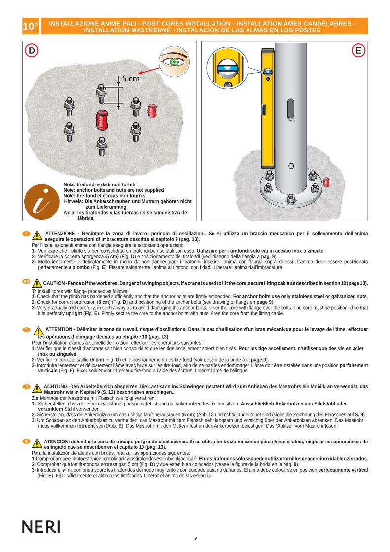
ATTENZIONE - Recintare la zona di lavoro, pericolo di oscillazioni. Se si utilizza un braccio meccanico per il sollevamento dell’animaeseguire le operazioni di imbracatura descritte al capitolo 9 (pag. 13).
Per l’installazione di anime con fl angia eseguire le sottostanti operazioni:1) Verifi care che il plinto sia ben consolidato e i tirafondi ben solidali con esso. Utilizzare per i tirafondi solo viti in acciaio inox o zincate.2) Verifi care la corretta sporgenza (5 cm) (Fig. D) e posizionamento dei tirafondi (vedi disegno della fl angia a pag. 9).3) Molto lentamente e delicatamente in modo da non danneggiare i tirafondi, inserire l’anima con fl angia sopra di essi. L’anima deve essere posizionata
perfettamente a piombo (Fig. E). Fissare saldamente l’anima ai tirafondi con i dadi. Liberare l’anima dall’imbracatura.
CAUTION - Fence off the work area. Danger of swinging objects. If a crane is used to lift the core, secure lifting cable as described in section 10 (page 13).
To install cores with fl ange proceed as follows:1) Check that the plinth has hardened suffi ciently and that the anchor bolts are fi rmly embedded. For anchor bolts use only stainless steel or galvanized nuts.2) Check for correct protrusion (5 cm) (Fig. D) and positioning of the anchor bolts (see drawing of fl ange on page 9).3) Very gradually and carefully, in such a way as to avoid damaging the anchor bolts, lower the core with fl ange over the bolts. The core must be positioned so that
it is perfectly upright (Fig. E). Firmly secure the core to the anchor bolts with nuts. Free the core from the lifting cable.
ATTENTION - Délimiter la zone de travail, risque d’oscillations. Dans le cas d’utilisation d’un bras mécanique pour le levage de l’âme, effectuer
les opérations d’élingage décrites au chapitre 10 (pag. 13).Pour l’installation d’âmes à semelle de fi xation, effectuer les opérations suivantes:1) Vérifi er que le massif d’ancrage soit bien consolidé et que les tige ascellement soient bien fi xés. Pour les tige ascellement, n’utiliser que des vis en acier
inox ou zinguées.2) Vérifi er la correcte saillie (5 cm) (Fig. D) et le positionnement des tire-fond (voir dessin de la bride à la page 9).3) Introduire lentement et délicatement l’âme avec bride sur les tire-fond, afi n de ne pas les endommager. L’âme doit être installée dans une position parfaitement
verticale (Fig. E). Fixer solidement l’âme aux tire-fond à l’aide des écrous. Libérer l’âme de l’élingue.
ACHTUNG -Den Arbeitsbereich absperren. Die Last kann ins Schwingen geraten! Wird zum Anheben des Mastrohrs ein Mobilkran verwendet, das Mastrohr wie in Kapitel 9 (S. 13) beschrieben anschlagen..
Zur Montage der Mastrohre mit Flansch wie folgt verfahren:1) Sicherstellen, dass der Sockel vollständig ausgehärtet ist und die Ankerbolzen fest in ihm sitzen. Ausschließlich Ankerbolzen aus Edelstahl oder
verzinktem Stahl verwenden.2) Sicherstellen, dass die Ankerbolzen um das richtige Maß herausragen (5 cm) (Abb. D) und richtig angeordnet sind (siehe die Zeichnung des Flansches auf S. 9).3) Um Schäden an den Ankerbolzen zu vermeiden, das Mastrohr mit dem Flansch sehr langsam und vorsichtig über den Ankerbolzen absenken. Das Mastrohr
muss vollkommen lotrecht sein (Abb. E). Das Mastrohr mit den Muttern fest an den Ankerbolzen befestigen. Das Stahlseil vom Mastrohr lösen.
ATENCIÓN: delimitar la zona de trabajo, peligro de oscilaciones. Si se utiliza un brazo mecánico para elevar el alma, respetar las operaciones de eslingado que se describen en el capítulo 10 (pág. 13).
Para la instalación de almas con bridas, realizar las operaciones siguientes:1) Comprobar que el plinto esté bien consolidado y los tirafondos estén bien fi jados a él. En los tirafondos sólo se pueden utilizar tornillos de acero inoxidable o zincados.2) Comprobar que los tirafondos sobresalgan 5 cm (Fig. D) y que estén bien colocados (véase la fi gura de la brida en la pág. 9).3) Introducir el alma con brida sobre los tirafondos de modo muy lento y con cuidado para no dañarlos. El alma debe colocarse en posición perfectamente vertical
(Fig. E). Fijar sólidamente el alma a los tirafondos. Liberar el ánima de las eslingas.
Nota: tirafondi e dadi non fornitiNote: anchor bolts and nuts are not suppliedNote: tire-fond et écrous non fournisHinweis: Die Ankerschrauben und Muttern gehören nicht
zum Lieferumfang.Nota: los tirafondos y las tuercas no se suministran de
fábrica.
10° INSTALLAZIONE ANIME PALI - POST CORES INSTALLATION - INSTALLATION ÂMES CANDÉLABRES - INSTALLATION MASTKERNE - INSTALACIÓN DE LAS ALMAS EN LOS POSTES

17
www.neri.biz
I
GB
F
D
E
12°
IMPORTANTE - Se l’impianto elettrico prescrive il collegamento a terra del palo, procedere utilizzando l’apposita vite M10 in acciaio inox posta alla base dell’anima e contrassegnata dal simbolo di messa a terra.
Il collegamento se da eseguire, và comunque fatto prima di iniziare a montare gli elementi del palo (base, colonna, ecc.), poiché la vite per il collegamento a terra risulta inaccessibile dopo aver installato i vari elementi del palo.
CAUTION - If the electrical system envisages a ground connection for the post, use the stainless steel M10 screw located at the bottom of the core, marked with the ground symbol.
If envisaged, the ground connection must always be made before the elements of the post are mounted (base, column, etc), as in some types of post the ground connection screw is inaccessible after the various elements of the post are installed.
ATTENTION - Si l’installation électrique prévoit le branchement à la terre du candélabre, utiliser la vis M10 en acier inox placée à cet effet à la base de l’âme et portant le symbole de mise à la terre.
La connexion doit toujours être effectuée avant de commencer le montage des éléments du candélabre (base, colonne, etc.) car, sur certains types de candélabres, la vis de branchement à la terre est inaccessible lorsque les différents éléments du candélabre ont été montés.
ACHTUNG - Wenn die Elektroanlage eine Erdung des Pfahls vorschreibt, verfährt man, indem man die eigens dafür vorgesehene M10- Edelstahlschraube verwendet, dies sich an der Basis der Seele befi ndet und durch das Erdungssymbol gekennzeichnet ist.
Die Verbindung, wenn man sie denn herstellen muss, sollte jedenfalls eingerichtet werden, bevor man mit der Montage der Pfahlelemente beginnt (Basis, Säule usw.), weil bei einigen Pfahltypen nachher die Erdungsschraube nicht mehr zugänglich ist.
IMPORTANTE - Si para realizar la instalación eléctrica es necesario conectar el poste a tierra, utilizar el tornillo M10 de acero inoxidable situado en la base del alma y marcado con el símbolo de puesta a tierra.
La eventual conexión se deberá realizar antes de montar los elementos del poste (base, columna, etc.), ya que no es posible acceder al tornillo de conexión a tierra después de haber instalado dichos elementos.
11° MESSA A TERRA - GROUND CONNECTION - MISE A LA TERRE - ERDUNG - COLOCACIÓN EN TIERRA
PROTEZIONI FINALI - FINAL PROTECTION - PROTECTIONS FINALES - SCHUTZBEHANDLUNG - PROTECCIÓN FINAL12°
A B
I
GB
F
D
E
IMPORTANTE - Al termine dell’installazione delle anime con fl angia verifi care scrupolosamente il serraggio dei dadi dei tirafondi (Fig. A).
Proteggere con prodotti contro la corrosione (vernici a base di zinco, grasso, ecc.) i dadi e le fi lettature dei tirafondi (Fig. B).
I tirafondi, i dadi e i prodotti protettivi non sono forniti.
IMPORTANT - After the installation of cores with fl anges, scrupulously check that the nuts on the anchor bolts have been fully tightened (Fig. A).
Protect nuts and anchor bolt threads with anti-corrosion products (zinc paint, grease, etc) (Fig. B).
Anchor bolts, nuts and anti-corrosion products are not supplied.
IMPORTANT - Au terme de l’installation des âmes à semelle de fi xation, contrôler scrupuleusement le serrage des écrous des tige ascellement (Fig. A).
Protéger les écrous et les fi letages des tige ascellement par des produits contre la corrosion (peintures à base de zinc, gras, etc.) (Fig. B).
Les tige ascellement, les vis et les produits de protection ne sont pas fournis.
WICHTIG - Nach Beendigung der Installation der Seelen mit Flansch sorgfältig überprüfen, dass die Muttern der Bodenbefestigungseisendübel fest angezogen sind (Fig. A).
Die Muttern und die Gewinde der Bodenbefestigungseisen mit Anti-Korrosionsprodukten schützen (Lacke auf Zinkbasis, Fett usw.) (Abb. B).
Die Bodenbefestigungseisendübel, die Muttern und die Schutzprodukte werden nicht mitgeliefert.
IMPORTANTE - Al fi nalizar la instalación de las almas con brida, comprobar escrupulosamente el apriete de las tuercas de los tirafondos (Fig. A).
Proteger con productos anticorrosión (pinturas de zinc, grasa, etc.) las tuercas y las roscas de los tirafondos (Fig. B).
Los tirafondos, las tuercas y los productos de protección no se incluyen en el suministro.

18
1320.6001320.6011320.7001320.701
1310.6001310.6011310.7001310.701
1295.0201295.021
1191.0501191.051
1351.7001351.7011351.8001351.801
4°
6°
10°
9°
13°
7° 11°
8° 12°
3°
9°
10°
5°
1°
14°
1°
2°
15°
2°
Rif.CODICE
CODE - CODECODE - CÓDIGO
Kg
1°2°3°4°5°6°7°8°9°
10°11°12°13°14°15°
9.501.1919.501.1909.501.1989.501.1059.501.1939.501.1949.501.3109.501.3119.501.3139.501.3589.501.320
95.010.3219.501.3229.501.3509.501.349
671
15,514,55238821,875
77,522
1824
Rif.
Cod.
TABELLA CODICE, RIFERIMENTO - TABLE CODE, REFERENCE - TABLEAU CODE, RÉFÉRENCE - TABELLE CODE, BEZUG - TABLA DE CÓDIGO, REFERENCIA

19
www.neri.biz
I I
I II I
I IA B
E FH G
C D
O
250 Kg
ATTENZIONECAUTION
ATTENTIONACHTUNGATENCIÓN
13°
E
F
D
I
GB
IMBRACATURA - HARNESSING - ÉLINGAGE - ANSCHLAGEN - ESLINGADO
ATTENZIONE - Recintare la zona di lavoro e attuare tutte le prescrizioni sull’uso in sicurezza di mezzi meccanici in movimento. In base al peso degli elementi (vedi tabella pesi a pag. 18) e all’altezza che dovranno essere sollevati è necessario utilizzare un braccio meccanico (Fig. A) più tre fasce in tessuto (O) senza ganci metallici con portata non inferiore a 250 Kg e lunghezza di circa tre metri.
Per imbragare gli elementi seguire gli esempi sotto elencati:1) Esempio di Figura B, C, D, E, F, G, H. L’elemento ha la parte alta terminale più larga del corpo centrale: va imbragato utilizzando due fasce, le quali vengonoavvolte attorno all’elemento in modo tale che ogni fascia crea un cappio, sistemarle poi in modo tale che l’elemento quando viene sollevato risulti il più possibile inposizione verticale.
CAUTION - Fence off the work area and implement all the prescriptions regarding the safe use of mechanical means in motion. Depending on the weight of the elements (see Weights Table on page 18) and the heights to be lifted a mechanical boom must be used (Fig. A) together with three fabric belts (O) without metal hooks having load-carrying capacity of at least 250 kg and length of about 3 m.
To secure the elements to be lifted follow the examples illustrated here:1) Examples in fi gs. B, C, D, E, F, G, H. The top of the element is wider than the central section. It must be secured with two straps wound around the centralsection, with each strap forming a loop and positioned in a way that allows the element to be as vertical as possible when lifted.
ATTENTION – Délimiter la zone de travail et réaliser toutes les prescriptions sur l’usage en toute sécurité de moyens mécaniques en mouvement. En fonction du poids des éléments (voir tableau des poids à la page 18) et de la hauteur à laquelle ils sont à soulever il est nécessaire d’utiliser un bras mécanique (Fig. A) avec trois sangles en tissu (O) sans crochets métalliques, avec une portée non inférieure à 250 kg et une longueur d’environ trois mètres.
Pour élinguer les éléments, suivre les exemples suivants:1) Exemple des fi gures B, C, D, E, F, G, H. La partie terminale supérieure de l’élément est plus large que le corps central: l’élément doit ainsi être élinguéà l’aidede deux sangles, chacune d’elles devant être enroulée autour de l’élément de façon à former un noeud coulant et placée de manière à soulever ce même élémentdans la position la plus verticale possible.
ACHTUNG - Den Arbeitsbereich absperren und allen Verordnungen in Bezug auf die sichere Verwendung von mechanischen, sich bewegenden Hilfsmitteln, folgen. Je nach Gewicht (siehe Seite 18 - Gewichtstabelle) und Höhe der anzuhebenden Elemente, müssen ein mechanischer Arm (Abb. A) sowie 3 Textilbänder (O) ohne Metallhaken mit einer Mindesttragfähigkeit von 250 kg und einer Länge von ca. 3 Metern verwendet werden.
Zum Anschirren der Elemente den u.a. Beispielen folgen:1) Beispiel der Fig. B, C, D, E, F, G, H. Beim Element ist das Endteil breiter als der Zentralkörper: es wird mit zwei Gurten angeschirrt, die so um dasElement gewunden werden, dass jeder eine Schlinge bildet; dann ordnet man sie so an, dass das Element beim Anheben möglichst senkrecht hängt.
ATENCIÓN: delimitar la zona de trabajo y respetar todas las normas de seguridad relativas al uso de medios mecánicos en movimiento. En función del peso de los elementos (véase la tabla de pesos de la pág. 18) y de la altura a la que se han izar, se deberá utilizar un brazo mecánico (Fig. A) y tres eslingas de tela (O) sin ganchos metálicos con capacidad para resistir cargas de más de 250 kg y una longitud de aproximadamente 3 m.
Para embragar los elementos sigan las instrucciones siguientes:1) Ejemplo de fi gura B, C, D, E, F, G, H. El elemento tiene la parte alta terminal más ancha que el cuerpo central: el elemento se embraga utilizando dos tiras que se enrollan alrededor del elemento de forma que cada tira crea un lazo, colóquenlas después de tal modo que el elemento, cuando se eleve, se mantenga lo más posible en posición vertical.

20
I IA B
ATTENZIONECAUTION
ATTENTIONACHTUNGATENCIÓN
I
=
=I
I
C
D
E
I
GB
14°
F G
H
INSTALLAZIONE - INSTALLATION - INSTALLATION - INSTALLIEREN - INSTALACIÓN
Attenzione. Recintare la zona di lavoro, pericolo di oscillazioni. Se si utilizza un braccio meccanico per il sollevamento eseguire le operazioni di imbracatura descritte al capitolo 13 (pag. 19) e attuare tutte le prescrizioni sull’uso in sicurezza di mezzi meccanici (Fig. A).
Per l’installazione eseguire le sottostanti operazioni:Operazioni di verifi ca:1) Verifi care che l’anima del palo sia saldamente ancorata al plinto;2) Verifi care la corretta posizione delle asole rispetto alla carreggiata stradale (vedi pag.14 - Guida installazione anime pali);3) Verifi care che la tacca di riferimento quota zero (segnalata sull’anima) corrisponda al piano di pavimentazione fi nale;4) Verifi care che il collegamento a terra dell’anima se prescritto sia stato eseguito.Montaggio degli elementi in ghisa:1) Consultare la tabella a pag. 18, per individuare il modello del palo e l’ordine di montaggio in successione degli elementi;2) Eseguire le operazioni di imbracatura descritte da pag. 19. E’ consigliato legare una corda all’elemento in modo tale che una personada terra possa guidare l’elemento e ridurre le oscillazioni. Sollevare l’elemento sopra la sommità dell’anima e poi farlo scendere su di essalentamente. Le basi dotate di portello devono essere posizionate in modo tale che l’asola dell’anima e apertura della base coincidano (Fig. B), (smontare il portello preassemblato in fabbrica). Sciogliere l’imbracatura solo dopo essere certi che il pozionamento è corretto;3) Gli elementi che non necessitano di un braccio meccanico per essere sollevati devono comunque essere movimentati in sicurezza, utilizzare quindi un braccio meccanico con cestello porta persone (Fig. A, C, D) per raggiungere la sommità dell’anima del palo. Gli elementi devono essere posizionati con cura l’uno sull’altro, facendo attenzione che si incastrino, in questo modo si evitano infi ltrazioni d’acqua all’interno del palo (Fig. E).4) Per i pali interessati (vedere pag. 18), installare dalla sommità del palo l’apposito raccordo decorativo (Fig. F). 5) Per i pali interessati (vedere pag. 18), installare nella mezzaria della lunghezza dell’anima l’apposito raccordo decorativo avvitando i tre appositi grani (Fig. G, H).Il palo è protetto dalla specifi ca pellicola antigraffi o. Al termine delle operazioni di installazione, rimuovere la pellicola antigraffi o.
Caution. Fence off the work area. Danger of swinging objects. If a crane is used, secure elements to lifting straps or ropes as describedin section 13 (pages 19) and take all precautions for the safe use of mechanical equipment (Fig. A).
For installation proceed as follows:Checks:1) Check that the post core is fi rmly anchored to the plinth.2) Check the correct position of slots with respect to the roadway (see page 14 – Guide to installation of post cores).3) Check that the reference mark for zero position (marked on core) corresponds to the fi nal level of paving.4) Check that the earth connection of the core, if envisaged, has been correctly made.Assembly of cast iron elements:1) Consult the charts on pages 18 to identify the post model and assembly sequence of elements.2) Secure elements as described on pages 19. It is advisable to tie a rope to the element to allow it to be guided by a person on the ground andto reduce swing. Lift the element above the top of the post core and slowly lower it onto the core. Bases with a hatch must be positioned withthe slot of the core and the aperture on the base correctly aligned (Fig. B) (remove hatch preassembled in factory). Remove the liftingharness only after checking that the position is correct.3) Elements that do not need to be lifted with a crane must nevertheless be handled in safety. Use an aerial platform (Figs. A, C, D) foraccess to the top of the post. The elements must be positioned carefully on top of each other, taking care that they are correctly fi tted togetherto prevent water infi ltrations inside the post (Fig. E).4) For the posts in question, (see page. 18), install the relative decorative junction from the top of the post (Fig. F). 5) For the posts in question, (see page. 18), install the relative decorative junction in the centre line of the core length by tightening the three grub screws (Fig. G, H).The post is protected by the special scratch-resistant fi lm. Once installation operations have been completed, remove the scratch-resistant fi lm.

21
www.neri.biz
F
D
E
14° INSTALLAZIONE - INSTALLATION - INSTALLATION - INSTALLIEREN - INSTALACIÓN
Attention. Délimiter la zone de travail, risque d’oscillations. Dans le cas d’utilisation d’un bras mécanique de levage, effectuer les opérationsd’élingage décrites au chapitre 13 (pag. 19) et respecter toutes les prescriptions de sécurité concernant l’utilisation d’appareils mécaniques (Fig. A).
Pour l’installation, effectuer les opérations suivantes:Opérations de vérifi cation:1) Vérifi er que l’âme du candélabre soit solidement scellée dans le massif d’ancrage.2) Vérifi er la juste position des boutonnières par rapport à la chaussée (voir pag. 14 - Manuel d’installation des âmes des candélabres).3) Vérifi er que l’encoche de repère “cote zéro” (indiquée sur l’âme) corresponde au plan de pavement fi nal.4) Vérifi er que le branchement de l’âme à la terre, s’il est indiqué, ait été effectué.Montage des éléments en fonte:1) Consulter le tableau à pag. 18 pour identifi er le modèle de candélabre ainsi que l’ordre des phases de montage des éléments;2) Effectuer les opérations d’élingage décrites de la page 19. Il est conseillé d’attacher une corde à l’élément pour permettre à unepersonne à terre de le guider et d’en réduire les oscillations. Soulever l’élément au-dessus du sommet de l’âme puis le faire descendre lentementsur celle-ci. Les bases dotées de volet doivent être positionnées de façon à ce que la boutonnière de l’âme et l’ouverture de la basecoïncident (Fig. A) (démonter le volet préassemblé en usine). Ne décorder l’élément qu’après avoir vérifi é que le positionnement est correct.3) Les éléments ne nécessitant pas de bras mécanique pour être soulevés doivent toutefois être déplacés en toute sécurité. Utiliser pour cela unbras mécanique doté de plate-forme élévatrice (Fig. A, C, D) pour atteindre le sommet de l’âme du candélabre. Les éléments doiventêtre positionnés avec soin l’un sur l’autre et bien encastrés, de façon à éviter toute infi ltration d’eau à l’intérieur du candélabre (Fig. E).4) Pour les candélabres affectés (voir page 18), installer par le sommet du candélabre le raccord décoratif (Fig. F) prévu à cet usage. 5) Pour les candélabres affectés (voir page 18), installer dans le milieu de la longueur de l’âme le raccord décoratif prévu à cet usage en vissant les trois doigts spéciaux (Fig. G, H).Le candélabre est protégé par le fi lm anti-rayures spécifi que. Une fois les opérations d’installation terminées, retirer le fi lm anti-rayures.
Achtung. Den Arbeitsbereich absperren, Schwingungsgefahr. Wenn man zum Anheben einen mechanischen Arm benutzt, die in Kap. 13 (Seite 19) beschriebenen Anschirrungsarbeiten erledigen und alle Vorschriften zum sicheren Einsatz von mechanischen Hilfsmitteln befolgen (Abb. A).
Zur Installation die folgenden Arbeiten durchführen:Kontrollarbeiten:1) Überprüfen, dass die Pfahlseele fest am Sockel verankert ist;2) Überprüfen, dass die Position der Pfahl/Seele-Öffnungen richtig zur Straßenführung hin ausgerichtet ist (siehe Seite 14 – Installationsanleitungfür Pfahlseelen);3) Überprüfen, dass das Bezugszeichen für Höhe Null (das sich an der Pfahlseele befi ndet) der endgültigen Pfl asterebene entspricht.4) Überprüfen, dass die Erdung der Pfahlseele – falls vorgeschrieben – ausgeführt worden ist.Montage der Elemente aus Gusseisen:1) Um das Pfahlmodell und die Montage-Reihenfolge der Elemente festzustellen, die Tabelle auf den Seiten 18 zu Rate ziehen.2) Die auf Seite 19 beschriebenen Anschirrarbeiten ausführen. Man sollte eine Leine so an das Element binden, dass es durch eine Person vomBoden aus geführt werden kann, wodurch die Schwingungen vermindert werden. Das Element über das Pfahlseelenende hinaus anheben unddann langsam um die Pfahlseele herum hinablassen. Die mit einer Öffnungsplatte versehenen Basen müssen so ausgerichtet werden, dassdie Öffnungen von Seele und Basis übereinstimmen (Fig. A), (die in der Fabrik zuvor schon aufgesetzte Platte abmontieren). DasMontagegeschirr erst lösen, wenn man sicher ist, das die Ausrichtung stimmt.3) Die Elemente bedürfen zur Anhebung keines mechanischen Arms, müssen jedoch in jedem Fall sicher bewegt werden, weshalb man einenmechanischen Arm mit einem Personenkorb (Fig. A. C, D) benutzen muss, um zum oberen Pfahlseelenende zu gelangen. Die Elementemüssen sorgfältig übereinander gesetzt werden, wobei darauf zu achten ist, dass sie sich ineinander fügen, wodurch man Wasserinfi ltrationen insPfahlinnere vermeidet (Fig. E).4) Am oberen Teil der betreffenden Masten (siehe Seite 18) den Dekroanschluss anbringen (Abb. F).5) An den betroffenen Masten (siehe Seite 18) das dafür bestimmte Dekoranschlussstück auf halber Höhe des Mastrohrs durch Einschrauben der drei Stifte (Abb. G, H) befestigen.Der Mast wird durch eine Kratzschutzfolie geschützt. Nach Beendigung der Installationsarbeiten, die Kratzschutzfolie entfernen.
Atención. Delimiten la zona de trabajo, peligro de oscilaciones. Si se utiliza un brazo mecánico para la elevación, realicen las operacionesde embragado descritas en el capítulo 13 (pag.19) y utilicen todas las normas de seguridad referidas a medios mecánicos (Fig. A).
Para la instalación sigan las operaciones siguientes:Operaciones de comprobación:1) Comprueben que el alma del palo esté anclada perfectamente al plinto.2) Comprueben la correcta posición de los ojales con respecto al nivel de la calzada (vean pag. 14) – guía de instalación almas de postes).3) Comprueben que la muesca que marca la cota cero (señalada en el alma) corresponda al nivel del pavimento fi nal.4) Comprueben que la conexión de tierra del alma haya sido realizada, si está prescrito.Montaje de los elementos de hierro colado:1) Consulten la tabla de pag 18 para localizar el modelo de poste y el orden de colocación de los elementos en forma sucesiva,2) Realicen las operaciones de embragado descritas en las páginas 19. Se aconseja atar una cuerda al elemento de forma que una personadesde tierra pueda guíar el elemento y reducir las oscilaciones. Eleven el elemento por encima del extremo del alma y después háganlodescender sobre la misma lentamente. Las bases dotadas de puertecilla deben ser colocadas de forma que el ojal del alma y la aberturade la base coincidan (Fig. A), (desmonten la puertecilla ensamblada en fábrica). Deshagan el embragado sólo después de haberse cercioradode que la posición es correcta,3) Los elementos que no necesitan de una grúa o brazo mecánico para ser elevados deben de todas formas desplazarse con seguridad, utilicenpor ello un brazo mecánico o grúa con cesta para personas (Fig. A, C, D) para alcanzar el extremo superior del alma del poste.Los elementos deben colocarse con cuidado uno sobre otro, poniendo atención a que se encastren para evitar infi ltraciones de agua en el interiordel poste (Fig. E).4) En aquellos postes que lo requieran (véase la pág. 18), instalar el embellecedor de unión en el extremo del poste (Fig. F).5) En los postes implicados (véase la pág. 18), instalar en la mediana de la longitud del alma el embellecedor de empalme y fi jarlo con los tres tornillos prisioneros correspondientes (Figs. G y H).El poste está protegido por una película antirrayas especial. Al terminar las operaciones de instalación, quitar la película antirrayas.
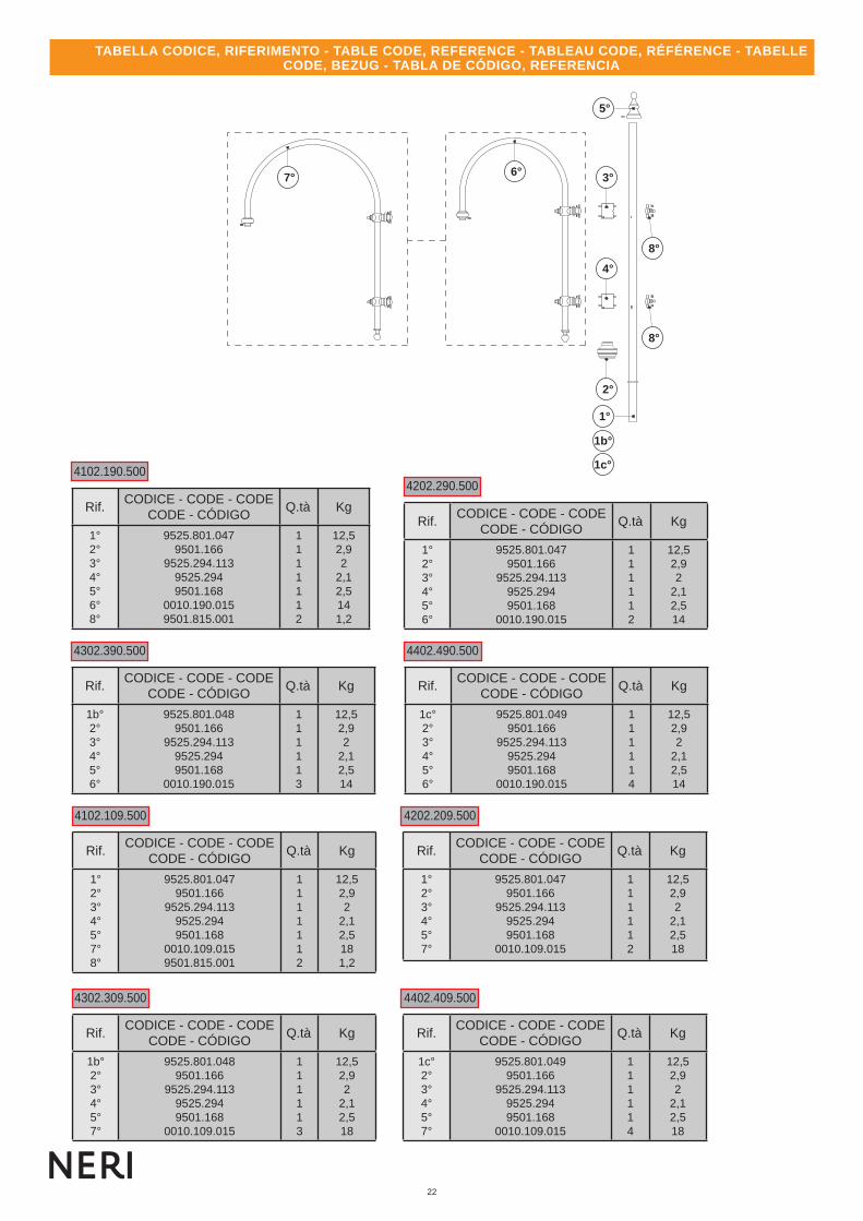
22
4102.109.500
4302.309.500
4202.209.500
4402.409.500
Rif.CODICE - CODE - CODE
CODE - CÓDIGOQ.tà Kg
1°2°3°4°5°7°8°
9525.801.0479501.166
9525.294.1139525.2949501.168
0010.109.0159501.815.001
1111112
12,52,92
2,12,5181,2
Rif.CODICE - CODE - CODE
CODE - CÓDIGOQ.tà Kg
1b°2°3°4°5°7°
9525.801.0489501.166
9525.294.1139525.2949501.168
0010.109.015
111113
12,52,92
2,12,518
Rif.CODICE - CODE - CODE
CODE - CÓDIGOQ.tà Kg
1°2°3°4°5°7°
9525.801.0479501.166
9525.294.1139525.2949501.168
0010.109.015
111112
12,52,92
2,12,518
Rif.CODICE - CODE - CODE
CODE - CÓDIGOQ.tà Kg
1c°2°3°4°5°7°
9525.801.0499501.166
9525.294.1139525.2949501.168
0010.109.015
111114
12,52,92
2,12,518
2°
6°7°
8°
1°
1b°
1c°
4°
3°
8°
4102.190.5004202.290.500
Rif.CODICE - CODE - CODE
CODE - CÓDIGOQ.tà Kg
1°2°3°4°5°6°8°
9525.801.0479501.166
9525.294.1139525.2949501.168
0010.190.0159501.815.001
1111112
12,52,92
2,12,5141,2
Rif.CODICE - CODE - CODE
CODE - CÓDIGOQ.tà Kg
1°2°3°4°5°6°
9525.801.0479501.166
9525.294.1139525.2949501.168
0010.190.015
111112
12,52,92
2,12,514
4302.390.500 4402.490.500
Rif.CODICE - CODE - CODE
CODE - CÓDIGOQ.tà Kg
1b°2°3°4°5°6°
9525.801.0489501.166
9525.294.1139525.2949501.168
0010.190.015
111113
12,52,92
2,12,514
Rif.CODICE - CODE - CODE
CODE - CÓDIGOQ.tà Kg
1c°2°3°4°5°6°
9525.801.0499501.166
9525.294.1139525.2949501.168
0010.190.015
111114
12,52,92
2,12,514
5°
TABELLA CODICE, RIFERIMENTO - TABLE CODE, REFERENCE - TABLEAU CODE, RÉFÉRENCE - TABELLE CODE, BEZUG - TABLA DE CÓDIGO, REFERENCIA

23
www.neri.biz
4101.100 4201.025/G 4301.025/G 4401.035/G
4402.034/G4302.034/G4302.024/G4202.024/G
4102.193.500 4202.293.500 4302.393.500 4402.493.500
9°
Cod.Rif.
CODICECODE - CODE
CODE - CÓDIGOKg
9°10°11°12°13°
14°x215°16°17°18°19°
9.525.0579.501.1759.501.1779.501.110
9.501.109.0019.501.277
9.501.176.0019504.005/G
9.525.326.0019.501.208
9504.004/G
0,48
142,43261116
15
Rif.CODICE
CODE - CODECODE - CÓDIGO
Kg
20°21°22°23°24°25°26°
26°B26°C27°28°
9501.2119.501.906
9.525.294.0049.501.815.001
9.525.2949.501.166
9.525.801.0479.525.801.0489.525.801.049
10.193.5009.501.278
10,3141,91,32
2.912,612,6 12,6341
16°(n°2)
19°(n°2)
27° 27°(n°2) 27°(n°3) 27°(n°4)
19°(n°3)19°(n°2) 19°(n°3)
16°(n°2) 16°(n°3)
11° 11° 11°
15° 15° 15°14°(n°2) 14°(n°2) 28°(n°3)
17°
17° 17°17° 17°
12°
12°
21° 21° 21° 21°
25° 25° 25° 25°
26° 26° 26°B 26°C
22° 22°22° 22°
24° 24° 24° 24°
23°
23°
12°
20° 20°20° 20°
18° 18°18° 18°
14°(n°2) 14°(n°2) 28°(n°3) 28°(n°3)
12°17°13° 13° 13°
11°
Ref.
10°
TABELLA CODICE, RIFERIMENTO - TABLE CODE, REFERENCE - TABLEAU CODE, RÉFÉRENCE - TABELLE CODE, BEZUG - TABLA DE CÓDIGO, REFERENCIA

24
Ø 14 mm max
Ø 14 mm max
20 Nm
IA
ATTENZIONECAUTION
ATTENTIONACHTUNGATENCIÓN
I I I
I II
I
B D E
I LF
C
I
I
G
H
60 m
m
50 m
m
I
15°
Attenzione. Recintare la zona di lavoro. Se si utilizza un braccio meccanico (Fig. A) per il sollevamento attuare tutte le prescrizioni sull’uso in sicurezza di mezzi meccanici.
Montaggio delle cime con mensole 4201.025/G, 4301.025/G, 4401.035/G.Per l’installazione eseguire le sottostanti operazioni:1) Consultare la tabella a pag. 23, per individuare il modello e il peso degli elementi della cima da installare.2) Inserire la colonna (Fig. B) sull’anima e sovrapporla ad incastro sull’elemento sottostante.3) Inserire il portamensole (Fig. C) sull’anima, avendo cura di avvitare una vite nell’asola presente nell’anima.
La vite, Fig. C, inserita nell’asola determina il posizionamento delle cime con due o tre bracci mensola come mostrato nello schema (Fig. D).Le mensole prima di essere installate sul portamensole devono essere cablate con un cavo elettrico non superiore a 14 mm di diametro (Fig. E). Verifi care attentamente la lunghezza necessaria del cavo.
4) Installare le mensole complete di cavo nelle apposite asole del portamensole (Fig. F). Attenzione, le mensole agganciate al portamensola devono subito esserefi ssate con i collari stringimensola (Fig. H). I cavi elettrici devono essere inseriti nell’asola presente alla sommità dell’anima in acciaio (Fig. G) e fatti scendereall’interno dell’anima del palo.5) Avvitare il tubino in acciaio zincato alla boccola fi lettata da 3/4”” GAS posta alla sommità dell’anima in acciaio (Fig. I). Il tubino è predisposto per il passaggio diun cavo elettrico con diametro massimo di 14 mm.6) Installare la cima decorata con foglie sul tubino in acciaio (Fig. L). Regolare avvitando o svitando il tubino in acciaio in modo che sporga di circa 60 mm dallacima in ghisa (Fig. L).
INSTALLAZIONE CIME - TOP SECTION INSTALLATION - INSTALLATION BOUQUETS - INSTALLATION KRONEN - INSTALACIÓN DE CIMAS
4201.025/G , 4301.025/G , 4401.035/G , 4101.100

25
www.neri.biz
GB
F
D
E
15°
Caution. Fence off the work area. If a crane is used to lift the core (Fig. A) take all precautions for the safe use of mechanical equipment.Installation of top sections with brackets 4201.025/G, 4301.025/G, 4401.035/G.For installation proceed as follows:1) Consult the chart on page 23 to identify the model and weight of the elements of the top section to be installed. 2) Fit the column (Fig. B) onto the core and place it over the element below.3) Fit the bracket support (Fig. C) onto the core, taking care to tighten the screw into the slot in the core.
The screw (Fig. C) projecting into the slot determines the position of top sections with two or three brackets, as shown in Fig. D).Before installation on the bracket support the brackets must be wired with a power cable no greater than 14 mm in diameter (Fig. E).Carefully check the length of power cable required.
4) Hook the bracket complete with cable onto the slots of the bracket support (Fig. F). Caution: The brackets hooked onto the bracket support must be immediatelysecured with the bracket collars (Fig. H). Insert the power cables into the slot at the top of the steel core (Fig. G) and pass them down into the core.5) Screw the small galvanized steel tube into the 3/4” GAS threaded bush at the top of the core (Fig. I). The tube is suitable for the passage of a power cable witha maximum diameter of 14 mm.6) Fit the element decorated with leaves onto the small steel tube (Fig. L). Screw the small steel tube in or out until a length of about 60 mm projects from the topof the cast iron element (Fig. L).
Attention. Délimiter la zone de travail. Dans le cas d’utilisation de bras mécanique (Fig. A) de levage, respecter toutes les prescriptions de sécurité concernant l’utilisation d’appareils mécaniques.
Montage des bouquets à consoles 4201.025/G, 4301.025/G, 4401.035/G.Pour l’installation, effectuer les opérations suivantes:1) Consulter le tableau à pag. 23, pour identifi er le modèle et le poids des éléments du bouquet à installer;2) Introduire la colonne (Fig. B) sur l’âme et l’encastrer sur l’élément sous-jacent;3) Introduire le porte-consoles (Fig. C) sur l’âme, en prenant soin de visser une vis dans la boutonnière située sur l’âme.
La vis (Fig. C) introduite dans l’âme détermine le positionnement des bouquets à deux ou trois consoles, tel qu’illustré sur le schéma (Fig. D).Pour l’installation, effectuer les opérations suivantes. Avant d’être installées sur le porte-consoles, les consoles doivent être câblées avec uncâble électrique non supérieur à 14 mm de diamètre (Fig. E). Vérifi er attentivement la longueur de câble nécessaire.
4) Installer les consoles équipées de câble sur le porte-consoles utilisant les boutonnières réservées à cet effet (Fig. F). Attention, les consoles accrochées auporte-consoles doivent être immédiatement fi xées par les colliers serre-console (Fig. H). Les câbles électriques doivent être introduits dans la boutonnière situéeau sommet de l’âme en acier (Fig. G) et descendre à l’intérieur de l’âme du candélabre;5) Visser le petit tube en acier zingué sur le manchon taraudé de 3/4” GAS placé au sommet de l’âme en acier (Fig. I). Ce petit tube est adapté aupassage d’uncâble électrique d’un diamètre maximal de 14 mm;6) Monter le bouquet décoré de feuilles sur le petit tube en acier (Fig. L). Régler la hauteur du petit tube en acier en le vissant ou le dévissant de façon à ce qu’ilsorte d’environ 60 mm du bouquet en fonte (Fig. L).
Achtung. Den Arbeitsbereich absperren. Wenn ein mechanischer Arm zum Anheben eingesetzt wird (Fig. A), alle Sicherheitsvorschriften für den Einsatz von mechanischen Hilfsmitteln anwenden.
Montage der Konsolenkronen 4201.025/G, 4301.025/G, 4401.035/G.Zur Installation die folgenden Operationen durchführen:1) Die Tabelle auf Seite 23 zu Rate ziehen, um das Modell und das Gewicht der Kronenelemente zu ermitteln.2) Die Säule über die Seele stülpen (Fig. B) und mit dem Element darunter zusammenfügen.3) Den Konsolenträger (Fig. C) auf der Seele anbringen und daran denken, eine Schraube im dafür vorgesehenen Loch der Seele anziehen.
Die in das Loch einführte Schraube (Fig. C) bestimmt die Positionierung der Kronen mit zwei oder drei Konsolenarmen, wie im Schema gezeigt wird (Fig. D).Zur Installation die folgenden Operationen durchführen. Bevor die Konsolen auf dem Konsolenträger installiert werden, müssen siemit einem Stromkabel, dessen Durchmesser nicht größer als 14 mm sein darf, verkabelt werden (Fig. E). Darauf achten, dass das Kabel die erforderliche Länge hat.
4) Die mit dem Kabel ergänzten Konsolen in die dafür vorgesehenen Öffnungen des Konsolenträgers einsetzen (Fig. F). Achtung, die an den Konsolenträgerangehängten Konsolen müssen sofort mit den Befestigungselementen verschraubt werden (Fig. H). Die Stromkabel müssen in die Öffnung am oberen Ende derSeele aus Stahl eingeführt (Fig. G) und dann darin hinunter gelassen werden.5) Das kleine Rohr aus verzinktem Stahl mit der 3/4” Gewindebuchse GAS verschrauben, die sich oben auf der Stahlseele befi ndet (Fig. I). Das kleine Rohr ist fürden Durchlass eines Stromkabels von höchstens 14 mm Durchmesser hergerichtet.6) Die Krone mit Blattdekoration auf dem kleinen Stahlrohr installieren (Fig. L). Das kleine Stahlrohr so hoch- oder runterschrauben, dass etwa 60 mm über dieGusseisenoberkante hinausragen (Fig. L).
Atención. Recinten la zona de trabajo. Si se utiliza un brazo mecánico (fi g A) para la elevación pongan en práctica todas las normas de seguridad para usar medios mecánicos.Montaje de cimas con ménsulas o brazos 4201.025/G, 4301.025/G, 4401.035/G.
Para la instalación sigan las operaciones siguientes:1) Consulten la tabla de la pag 23 para elegir el modelo y el peso de los elementos de las cima que se instalará;2) Introduzcan la columna (Fig. B) sobre el alma y sobrepónganla encastrada sobre el elemento inferior;3) Introduzcan el apoyaménsulas (Fig. C) sobre el alma, teniendo cuidado de atornillar un tornillo del ojal presente en el alma.
El tornillo (Fig. C) introducido en el ojal determina la colocación de las cimas con dos o tres brazos ménsulas como muestra el esquema (Fig. D).
Para la instalación sigan las operaciones siguientes. Antes de instalar las ménsulas o brazos en el apoyaménsulas, éstas deben ser cableadas con un cable eléctrico no superior a 14 mm de diámetro (Fig. E). Comprueben con atención la longitud de cable necesaria.
4) Instalen la ménsula completa de cable en el expreso ojal del apoyaménsulas (Fig. F). Atención, las ménsulas enganchadas al apoyaménsulas deben fi jarse conabrazaderas aprietaménsulas (Fig. H). Los cables eléctricos deben introducirse en el ojal presente en la parte superior del alma de acero (fi g G) y hacerlosdescender por el alma del poste.;5) Atornillen el tubito de acero cincado a la boquilla fi leteada de 3/ 4” “GAS colocada en la parte superior del alma de acero (Fig. I). El tubito está preparado parael paso de un cable eléctrico con diámetro máximo de 14 mm;6) Instalen la cima decorada con hojas sobre el tubito de acero (Fig. L). Regulen atornillando o afl ojando el tubito de acero de modo que unos 60 mm sobresalgande la cima de hierro colado (Fig. L).
INSTALLAZIONE CIME - TOP SECTION INSTALLATION - INSTALLATION BOUQUETS - INSTALLATION KRONEN - INSTALACIÓN DE CIMAS
4201.025/G , 4301.025/G , 4401.035/G , 4101.100
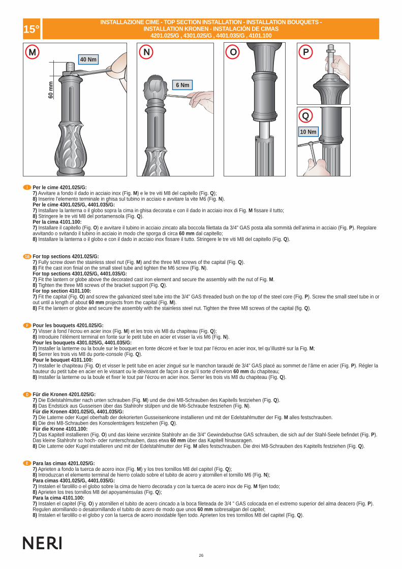
26
60 m
m
40 Nm
6 Nm
10 Nm
I I I I
I
M N O P
Q
I
GB
F
D
E
15°
Per le cime 4201.025/G:7) Avvitare a fondo il dado in acciaio inox (Fig. M) e le tre viti M8 del capitello (Fig. Q);8) Inserire l’elemento terminale in ghisa sul tubino in acciaio e avvitare la vite M6 (Fig. N).Per le cime 4301.025/G, 4401.035/G:7) Installare la lanterna o il globo sopra la cima in ghisa decorata e con il dado in acciaio inox di Fig. M fi ssare il tutto;8) Stringere le tre viti M8 del portamensola (Fig. Q).Per la cima 4101.100:7) Installare il capitello (Fig. O) e avvitare il tubino in acciaio zincato alla boccola fi lettata da 3/4” GAS posta alla sommità dell’anima in acciaio (Fig. P). Regolareavvitando o svitando il tubino in acciaio in modo che sporga di circa 60 mm dal capitello;8) Installare la lanterna o il globo e con il dado in acciaio inox fi ssare il tutto. Stringere le tre viti M8 del capitello (Fig. Q).
For top sections 4201.025/G:7) Fully screw down the stainless steel nut (Fig. M) and the three M8 screws of the capital (Fig. Q).8) Fit the cast iron fi nial on the small steel tube and tighten the M6 screw (Fig. N).For top sections 4301.025/G, 4401.035/G:7) Fit the lantern or globe above the decorated cast iron element and secure the assembly with the nut of Fig. M.8) Tighten the three M8 screws of the bracket support (Fig. Q).For top section 4101.100:7) Fit the capital (Fig. O) and screw the galvanized steel tube into the 3/4” GAS threaded bush on the top of the steel core (Fig. P). Screw the small steel tube in orout until a length of about 60 mm projects from the capital (Fig. M).8) Fit the lantern or globe and secure the assembly with the stainless steel nut. Tighten the three M8 screws of the capital (fi g. Q).
Pour les bouquets 4201.025/G:7) Visser à fond l’écrou en acier inox (Fig. M) et les trois vis M8 du chapiteau (Fig. Q);8) Introduire l’élément terminal en fonte sur le petit tube en acier et visser la vis M6 (Fig. N).Pour les bouquets 4301.025/G, 4401.035/G:7) Installer la lanterne ou la boule sur le bouquet en fonte décoré et fi xer le tout par l’écrou en acier inox, tel qu’illustré sur la Fig. M;8) Serrer les trois vis M8 du porte-console (Fig. Q).Pour le bouquet 4101.100:7) Installer le chapiteau (Fig. O) et visser le petit tube en acier zingué sur le manchon taraudé de 3/4” GAS placé au sommet de l’âme en acier (Fig. P). Régler lahauteur du petit tube en acier en le vissant ou le dévissant de façon à ce qu’il sorte d’environ 60 mm du chapiteau;8) Installer la lanterne ou la boule et fi xer le tout par l’écrou en acier inox. Serrer les trois vis M8 du chapiteau (Fig. Q).
Für die Kronen 4201.025/G:7) Die Edelstahlmutter nach unten schrauben (Fig. M) und die drei M8-Schrauben des Kapitells festziehen (Fig. Q).8) Das Endstück aus Gusseisen über das Stahlrohr stülpen und die M6-Schraube festziehen (Fig. N).Für die Kronen 4301.025/G, 4401.035/G:7) Die Laterne oder Kugel oberhalb der dekorierten Gusseisenkrone installieren und mit der Edelstahlmutter der Fig. M alles festschrauben.8) Die drei M8-Schrauben des Konsolenträgers festziehen (Fig. Q).Für die Krone 4101.100:7) Das Kapitell installieren (Fig. O) und das kleine verzinkte Stahlrohr an die 3/4” Gewindebuchse GAS schrauben, die sich auf der Stahl-Seele befi ndet (Fig. P).Das kleine Stahlrohr so hoch- oder runterschrauben, dass etwa 60 mm über das Kapitell hinausragen.8) Die Laterne oder Kugel installieren und mit der Edelstahlmutter der Fig. M alles festschrauben. Die drei M8-Schrauben des Kapitells festziehen (Fig. Q).
Para las cimas 4201.025/G:7) Aprieten a fondo la tuerca de acero inox (Fig. M) y los tres tornillos M8 del capitel (Fig. Q);8) Introduzcan el elemento terminal de hierro colado sobre el tubito de acero y atornillen el tornillo M6 (Fig. N);Para cimas 4301.025/G, 4401.035/G:7) Instalen el farolillo o el globo sobre la cima de hierro decorada y con la tuerca de acero inox de Fig. M fi jen todo;8) Aprieten los tres tornillos M8 del apoyaménsulas (Fig. Q);Para la cima 4101.100:7) Instalen el capitel (Fig. O) y atornillen el tubito de acero cincado a la boca fi leteada de 3/4 ” GAS colocada en el extremo superior del alma deacero (Fig. P).Regulen atornillando o desatornillando el tubito de acero de modo que unos 60 mm sobresalgan del capitel;8) Instalen el farolillo o el globo y con la tuerca de acero inoxidable fi jen todo. Aprieten los tres tornillos M8 del capitel (Fig. Q).
INSTALLAZIONE CIME - TOP SECTION INSTALLATION - INSTALLATION BOUQUETS - INSTALLATION KRONEN - INSTALACIÓN DE CIMAS
4201.025/G , 4301.025/G , 4401.035/G , 4101.100
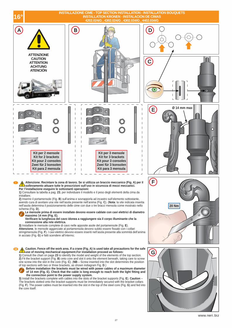
27
www.neri.biz
16°
IA
ATTENZIONECAUTION
ATTENTIONACHTUNGATENCIÓN
I
I
I
D
C
E Ø 14 mm max
I
I
F
G
IB
20 Nm
I
GB
Kit per 2 mensoleKit for 2 brackets
Kit pour 2 consolesZwei für 2 konsolenKit para 2 mensula
Kit per 3 mensoleKit for 3 brackets
Kit pour 3 consolesZwei für 3 konsolenKit para 3 mensula
Attenzione. Recintare la zona di lavoro. Se si utilizza un braccio meccanico (Fig. A) per il sollevamento attuare tutte le prescrizioni sull’uso in sicurezza di mezzi meccanici.Per l’installazione eseguire le sottostanti operazioni:1) Consultare la tabella a pag. 23, per individuare il modello e il peso degli elementi della cima dainstallare;2) Inserire il portamensole (Fig. B) sull’anima e sovrapporla ad incastro sull’elemento sottostante,avendo cura di avvitare una vite nell’asola presente nell’anima (Fig. C). (Nota: la vite indicata inseritanell’asola determina il posizionamento delle cime con due o tre bracci mensola come mostrato nelloschema (Fig. D).
Le mensole prima di essere installate devono essere cablate con cavi elettrici di diametromassimo 14 mm (Fig. E). Verifi care la lunghezza del cavo idonea a raggiungere sia il corpo illuminante che laconnessione alla rete elettrica.
3) Installare le mensole complete di cavo nelle apposite asole del portamensole (Fig. E). Attenzione, le mensole agganciate al portamensola devono subito essere fi ssate con i collaristringimensola (Fig. F). I cavi elettrici devono essere inseriti nell’asola presente alla sommità dell’animain acciaio (Fig. G) e fatti scendere all’interno;
Caution. Fence off the work area. If a crane (Fig. A) is used take all precautions for the safe use of moving mechanical equipment.For installation proceed as follows:
1) Consult the chart on page 23 to identify the model and weight of the elements of the top section.2) Fit the bracket support (Fig. B) onto core and slot it onto the element beneath, taking care to screwone screw into the slot in the core (Fig. C). (NB – Screw inserted into the slot determines the positionof top sections with two or three brackets, as shown indiagram Fig. D.)
Before installation the brackets must be wired with power cables of a maximum diameter of 14 mm (Fig. E). Check that the cable is long enough to reach both the light fi tting and the connection point to the power supply system.
3) Install the brackets complete with cables into the slots of the bracket supports (Fig. E). Caution –The brackets slotted onto the bracket supports must be immediately secured with the bracket collars(Fig. F). The power cables must be inserted into the slot in the top of the steel core (Fig. G) and fed intothe core itself.
INSTALLAZIONE CIME - TOP SECTION INSTALLATION - INSTALLATION BOUQUETSINSTALLATION KRONEN - INSTALACIÓN DE CIMAS
4202.024/G , 4302.024/G , 4302.034/G , 4402.034/G

28
16°
16°
60 m
m
35 m
m40 Nm
6 Nm
I I I I
I
I
H I L O
M
N
F
D
E
I
GB
Attention. Délimiter la zone de travail. Dans le cas d’utilisation d’un bras mécanique de levage (Fig. A), respecter toutes les prescriptions de sécurité concernant l’utilisation d’appareils mécaniques.
Pour l’installation, effectuer les opérations suivantes:1) Consulter le tableau à pag. 23, pour identifi er le modèle et le poids des éléments du bouquet à installer;2) Introduire le porte-consoles (Fig. B) sur l’âme et l’encastrer sur l’élément sous-jacent, en ayant soin de visser une vis dans le trou se trouvant sur l’âme (Fig. C).
Note: la vis introduite dans le trou détermine le positionnement des bouquets à deux ou trois consoles, comme illustré sur le schéma (Fig. D). Note: avant d’être installées, les consoles doivent être câblées avec des câbles électriques d’un diamètre maximal de 14 mm (Fig. E).
Vérifi er que la longueur du câble soit suffi sante pour atteindre tant le luminaire que la connexion au réseau électrique.3) Placer les consoles munies de leur câble dans les ouvertures spécialement aménagées sur le porte-consoles (Fig. E). Attention, les consoles accrochées auporte-consoles doivent immédiatement être fi xées au moyen des colliers de serrage pour consoles (Fig. F). Les câbles électriquesdoivent être introduits dansl’ouverture située au sommet de l’âme en acier (Fig. G) et descendre à l’intérieur de celle-ci.
Achtung. Arbeitsbereich absperren. Wenn man zum Anheben einen mechanischen Arm benutzt (Fig. A), alle Vorschriften für den sicheren Gebrauch mechanischer Hilfsmittel befolgen.
Zur Installation die folgenden Arbeiten durchführen:1) In der Tabelle auf S. 23 das Kronenmodell und das Gewicht der Elemente feststellen.2) Den Konsolenträger (Fig. B) auf die Pfahlseele geben und über das Element darunter stülpen, wobei dann eine Schraube in dem entsprechenden Loch derPfahlseele festgezogen werden muss (Fig. C).
Anmerkung: durch die Schraube wird die Positionierung der Kronen mit zwei oder drei Konsolen – wie im Schema dargestellt – festgelegt (Fig. D).
Anmerkung: bevor man die Konsolen installiert, müssen sie mit Kabeln, deren Durchmesser höchstens 14 mm beträgt, verkabelt werden (Fig. E). Kontrollieren, dass die Länge des Kabels genügt, um sowohl den Beleuchtungskörper wie das Stromnetz zu erreichen.3) Die mit Kabel versehenen Konsolen in den dafür vorgesehenen Löchern desKonsolenträgers anbringen (Fig. E). Achtung, die in die Löcher des Konsolenträgerseingehängten Konsolen müssen sofort mit den Zwingen (Fig. F) fi xiert werden. DieElektrokabel müssen in die Öffnung oben an der Pfahlseele aus Stahl eingeführt(Fig. G) und dann innen hinab gelassen werden.
Atención. Delimiten la zona de trabajo; si se utiliza un brazo mecánico (Fig. A) para elevar los elementos, utilicen las normas de seguridad obligatorias para usar dichas grúas y medios mecánicos.
Para la instalación sigan las operaciones siguientes:1) Consulten la tabla de pag. 23 para localizar el modelo y el peso de los elementos de la cima a instalar;2) Introduzcan el portaménsulas (Fig. B) sobre el alma y colóquenla encastrada sobre el elemento inferior, teniendo en cuenta de atornillar un tornillo en el ojalpresente en el alma (Fig. C).
Nota: el tornillo introducido en el alma determina la posición de las cimas con dos o tres brazos ménsula como se muestra en el esquema (Fig. D).
Nota: Las ménsulas, antes de ser instaladas, deben ser cableadas con cables eléctricos de 14 mm máximo de diámetro (Fig. E). Comprueben la longitud idónea del cable para que alcance el cuerpo iluminador y la conexión a la red eléctrica.3) Instalen las ménsulas completas de cable en las correspondientes aberturas delportaménsulas (Fig. E). Atención: las ménsulas enganchadas al portaménsulas debenser fíjadas rápidamente con los collares aprietaménsulas (Fig. F). Los cables eléctricosdeben introducirse en los ojales presentes en el extremo superior delalma de acero (Fig. G) y se harán descender por el interior.
Per l’installazione eseguire le sottostanti operazioni:4) Avvitare il tubino in acciaio zincato alla boccola fi lettata da 3/4” GAS posta alla sommità dell’anima in acciaio (Fig. H). Il tubino è predisposto per il passaggio diun cavo elettrico con diametro massimo di 14 mm;5) Installare la cima decorata con foglie sul tubino in acciaio (Fig. I).Per le cime 4202.024/G, 4302.034/G:1) Regolare avvitando o svitando il tubino in modo che sporga circa 60 mm dalla cima in ghisa (Fig. L), stringere a fondo il dado;2) Inserire l’elemento terminale in ghisa (Fig. M), e avvitare la vite M6 (Fig. N).Per le cime 4302.024/G, 4402.034/G:1) Regolare avvitando o svitando il tubino in modo che circa 35 mm sporgano dalla cima in ghisa (Fig. O), installare la lanterna o il globo sopra la cima in ghisadecorata e con il dado in acciaio inox da 3/4” GAS fi ssare il tutto;
For installation proceed as follows:4) Screw the galvanized steel tube into the 3/4” GAS threaded bush on top of the post core (Fig. H). The tube is suitable for the passage of a power cable with amaximum diameter of 14 mm.5) Install element decorated with leaves onto the steel tube (Fig. I).For top sections 4202.024/G, 4302.034/G:1) Adjust by screwing or unscrewing the tube so that about 60 mm projects from the cast iron element (Fig. L). Fully tighten the nut.2) Insert upper terminal in cast iron element (Fig. M) and tighten M6 screw (Fig. N).For top sections 4302.024/G, 4402.034/G:1) Adjust by screwing or unscrewing the tube so that about 35 mm projects from the cast iron element (Fig. O), fi t the lantern or globe onto the decorated cast ironelement and secure the tube with the 3/4” GAS stainless steel nut.
INSTALLAZIONE CIME - TOP SECTION INSTALLATION - INSTALLATION BOUQUETSINSTALLATION KRONEN - INSTALACIÓN DE CIMAS
4202.024/G , 4302.024/G , 4302.034/G , 4402.034/G
INSTALLAZIONE CIME - TOP SECTION INSTALLATION - INSTALLATION BOUQUETSINSTALLATION KRONEN - INSTALACIÓN DE CIMAS
4202.024/G , 4302.024/G , 4302.034/G , 4402.034/G

29
www.neri.biz
16°F
D
E
Pour l’installation, effectuer les opérations suivantes:4) Visser le petit tube en acier zingué sur le manchon taraudé de 3/4” GAS placé au sommet de l’âme en acier (Fig. H). Ce petit tube est adapté au passage d’uncâble électrique d’un diamètre maximal de 14 mm.5) Monter le bouquet décoré de feuilles sur le petit tube en acier (Fig. I).Pour les bouquets 4202.024/G, 4302.034/G:1) Régler la hauteur du petit tube en le vissant ou en le dévissant de façon à ce qu’il sorte d’environ 60 mm du bouquet en fonte (Fig. L), serrer l’écrou à fond;2) Introduire l’élément terminal en fonte (Fig. M) et visser la vis M6 (Fig. N).Pour les bouquets 4302.024/G, 4402.034/G:1) Régler la hauteur du petit tube en le vissant ou en le dévissant de façon à ce qu’il sorte d’environ 35 mm du bouquet en fonte (Fig. O), installer la lanterne ou laboule sur le bouquet en fonte décoré et fi xer le tout par l’écrou en acier inox de 3/4” GAS.Zur Installation die folgenden Arbeiten durchführen:4) Das kleine verzinkte Stahlrohr mit der 3/4“GAS-Gewindebuchse verschrauben, die sich oben an der Pfahlseele aus Stahl befi ndet (Fig. H). Das kleine Stahlrohrist hergerichtet für den Durchlass eines Elektrokabels von höchstens 14 mm Durchmesser.5) Die mit Blättern dekorierte Krone auf dem Stahlrohr anbringen (Fig. I).Für die Kronen 4202.024/G, 4302.034/G:1) Durch Rein- oder Rausschrauben das kleine Rohr so einstellen, dass etwa 60 mm über die Gusseisenkrone hinausragen (Fig. L), dann die Mutter bis auf denGrund schrauben.2) Das gusseiserne Endstück aufsetzen (Fig. M) und die M6-Schraube festziehen (Fig. N).Für die Kronen 4302.024/G, 4402.034/G:1) Durch Rein- oder Rausschrauben das kleine Rohr so einstellen, dass etwa 35 mm über die Gusseisenkrone hinausragen (Fig. O), die Laterne oder Kugel auf dergusseisernen dekorierten Krone installieren und das ganze mit der 3/4“GAS-Edelstahlmutter feststellen.Para la instalación sigan las operaciones siguientes:4) Atornillen el tubito de acero cincado a la boca roscada de 3/4” GAS situada en la parte superior del alma de acero (Fig. H). El tubito está preparado para el pasode un cable eléctrico con diámetro máximo de 14 mm;5) Instalen la cima decorada con hojas sobre el tubito de acero (Fig. I).Para las cimas 4202.024/G, 4302.034/G:1) Regulen apretando o afl ojando el tubito de forma que unos 60 mm sobresalgan de la cima de hierro colado (Fig. L), aprieten a fondo la tuerca;2) Introduzcan el elemento terminal de hierro colado (Fig. M) y atornillen el tornillo M6 (Fig. N).Para las cimas 4302.024/G, 4402.034/G:1) Regulen atornillando o desatornillando el tubito de modo que sobresalga unos 35 mm de la cima de hierro colado (Fig. O); instalen el farolillo o el globo sobrela cima de hierro colado decorado y con la tuerca inoxidable de 3/4 “ GAS fi jen todo ello;
INSTALLAZIONE CIME - TOP SECTION INSTALLATION - INSTALLATION BOUQUETSINSTALLATION KRONEN - INSTALACIÓN DE CIMAS
4202.024/G , 4302.024/G , 4302.034/G , 4402.034/G
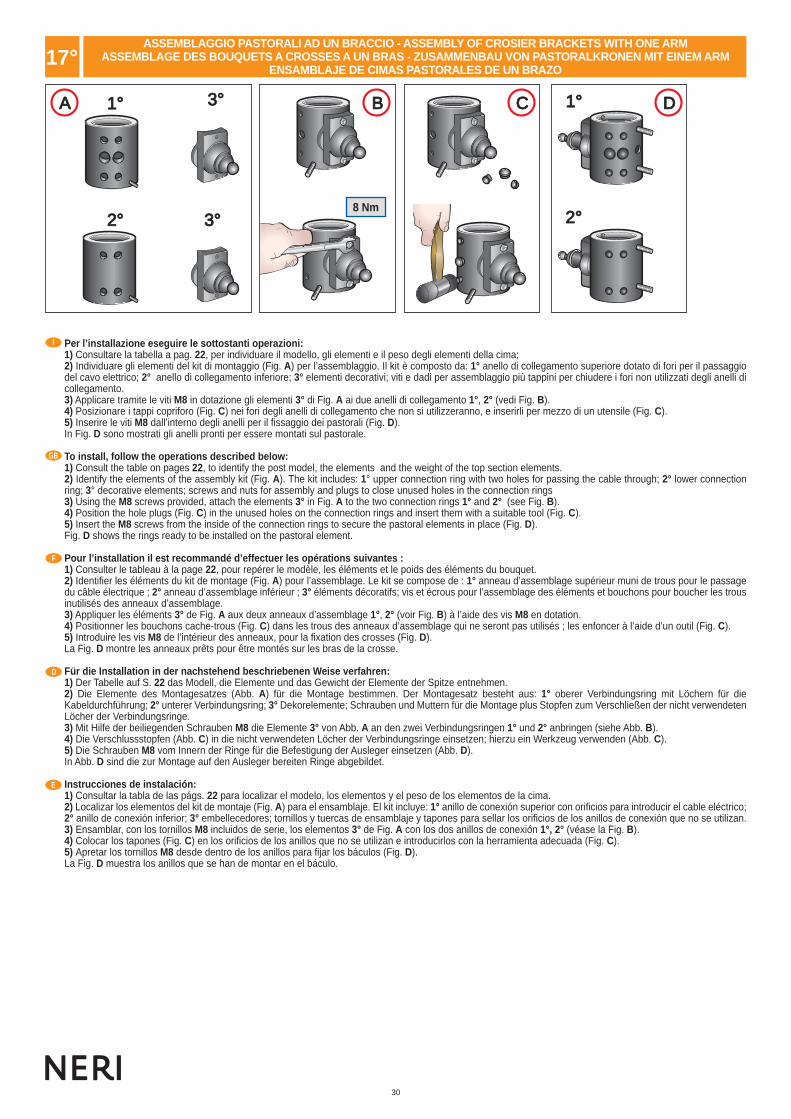
30
I
GB
F
D
E
15°
I I I IA B C D1°1° 1°1°
2°2° 2°2°3°3°
3°3°
17°
8 Nm
Per l’installazione eseguire le sottostanti operazioni:1) Consultare la tabella a pag. 22, per individuare il modello, gli elementi e il peso degli elementi della cima;2) Individuare gli elementi del kit di montaggio (Fig. A) per l’assemblaggio. Il kit è composto da: 1° anello di collegamento superiore dotato di fori per il passaggio del cavo elettrico; 2° anello di collegamento inferiore; 3° elementi decorativi; viti e dadi per assemblaggio più tappini per chiudere i fori non utilizzati degli anelli di collegamento.3) Applicare tramite le viti M8 in dotazione gli elementi 3° di Fig. A ai due anelli di collegamento 1°, 2° (vedi Fig. B).4) Posizionare i tappi copriforo (Fig. C) nei fori degli anelli di collegamento che non si utilizzeranno, e inserirli per mezzo di un utensile (Fig. C).5) Inserire le viti M8 dall’interno degli anelli per il fi ssaggio dei pastorali (Fig. D). In Fig. D sono mostrati gli anelli pronti per essere montati sul pastorale.
To install, follow the operations described below:1) Consult the table on pages 22, to identify the post model, the elements and the weight of the top section elements. 2) Identify the elements of the assembly kit (Fig. A). The kit includes: 1° upper connection ring with two holes for passing the cable through; 2° lower connection ring; 3° decorative elements; screws and nuts for assembly and plugs to close unused holes in the connection rings3) Using the M8 screws provided, attach the elements 3° in Fig. A to the two connection rings 1° and 2° (see Fig. B).4) Position the hole plugs (Fig. C) in the unused holes on the connection rings and insert them with a suitable tool (Fig. C).5) Insert the M8 screws from the inside of the connection rings to secure the pastoral elements in place (Fig. D). Fig. D shows the rings ready to be installed on the pastoral element.
Pour l’installation il est recommandé d’effectuer les opérations suivantes :1) Consulter le tableau à la page 22, pour repérer le modèle, les éléments et le poids des éléments du bouquet.2) Identifi er les éléments du kit de montage (Fig. A) pour l’assemblage. Le kit se compose de : 1° anneau d’assemblage supérieur muni de trous pour le passage du câble électrique ; 2° anneau d’assemblage inférieur ; 3° éléments décoratifs; vis et écrous pour l’assemblage des éléments et bouchons pour boucher les trous inutilisés des anneaux d’assemblage.3) Appliquer les éléments 3° de Fig. A aux deux anneaux d’assemblage 1°, 2° (voir Fig. B) à l’aide des vis M8 en dotation.4) Positionner les bouchons cache-trous (Fig. C) dans les trous des anneaux d’assemblage qui ne seront pas utilisés ; les enfoncer à l’aide d’un outil (Fig. C).5) Introduire les vis M8 de l’intérieur des anneaux, pour la fi xation des crosses (Fig. D). La Fig. D montre les anneaux prêts pour être montés sur les bras de la crosse.
Für die Installation in der nachstehend beschriebenen Weise verfahren:1) Der Tabelle auf S. 22 das Modell, die Elemente und das Gewicht der Elemente der Spitze entnehmen.2) Die Elemente des Montagesatzes (Abb. A) für die Montage bestimmen. Der Montagesatz besteht aus: 1° oberer Verbindungsring mit Löchern für die Kabeldurchführung; 2° unterer Verbindungsring; 3° Dekorelemente; Schrauben und Muttern für die Montage plus Stopfen zum Verschließen der nicht verwendeten Löcher der Verbindungsringe.3) Mit Hilfe der beiliegenden Schrauben M8 die Elemente 3° von Abb. A an den zwei Verbindungsringen 1° und 2° anbringen (siehe Abb. B).4) Die Verschlussstopfen (Abb. C) in die nicht verwendeten Löcher der Verbindungsringe einsetzen; hierzu ein Werkzeug verwenden (Abb. C).5) Die Schrauben M8 vom Innern der Ringe für die Befestigung der Ausleger einsetzen (Abb. D). In Abb. D sind die zur Montage auf den Ausleger bereiten Ringe abgebildet.
Instrucciones de instalación:1) Consultar la tabla de las págs. 22 para localizar el modelo, los elementos y el peso de los elementos de la cima.2) Localizar los elementos del kit de montaje (Fig. A) para el ensamblaje. El kit incluye: 1° anillo de conexión superior con orifi cios para introducir el cable eléctrico; 2° anillo de conexión inferior; 3° embellecedores; tornillos y tuercas de ensamblaje y tapones para sellar los orifi cios de los anillos de conexión que no se utilizan.3) Ensamblar, con los tornillos M8 incluidos de serie, los elementos 3° de Fig. A con los dos anillos de conexión 1°, 2° (véase la Fig. B).4) Colocar los tapones (Fig. C) en los orifi cios de los anillos que no se utilizan e introducirlos con la herramienta adecuada (Fig. C).5) Apretar los tornillos M8 desde dentro de los anillos para fi jar los báculos (Fig. D). La Fig. D muestra los anillos que se han de montar en el báculo.
ASSEMBLAGGIO PASTORALI AD UN BRACCIO - ASSEMBLY OF CROSIER BRACKETS WITH ONE ARMASSEMBLAGE DES BOUQUETS A CROSSES A UN BRAS - ZUSAMMENBAU VON PASTORALKRONEN MIT EINEM ARM
ENSAMBLAJE DE CIMAS PASTORALES DE UN BRAZO

31
www.neri.biz
I
GB
15°
1°1°
2°2°
E F G H
L M N
17°
10 Nm
10 Nm
10 Nm
1) Inserire il raccordo decorativo sul tubo della cima (Fig. E e F).2) Inserire l’anello inferiore 2° e fi ssarlo provvisoriamente al tubo con l’apposito grano indicato, in corrispondenza dell’asola sul tubo stesso (Fig. G). 3) Inserire l’anello superiore 1° e fi ssarlo provvisoriamente al tubo con l’apposito grano indicato, in corrispondenza del foro sul tubo stesso (Fig. G).4) Misurare quindi la quantità di cavo elettrico necessaria per collegare il corpo illuminante alla morsettiera, alla base del palo (Fig. H).5) Inserire il cavo elettrico all’interno del pastorale creando una matassa nel lato palo (Fig. L).6) Inserire il cavo elettrico all’interno dell’apposito foro sull’anello superiore e farlo scendere fi no alla base della cima (Fig. M).7) Fissare il pastorale agli anelli sul tubo serrando i dadi indicati (Fig. N).8) Bloccare defi nitivamente gli anelli inferiore e superiore al palo della cima serrando i grani indicati (Fig. G).
1) Insert the decorative junction on the top section pipe (Fig. E and F).2) Insert the lower ring 2° and fasten it momentarily to the pipe using the grub screw indicated where the slot on the pipe is (Fig. G). 3) Insert the upper ring 1° and fasten it momentarily to the pipe using the grub screw indicated where the hole in the pipe is (Fig. G).4) Measure the length of cable needed to connect the light fi xture to the terminal board at the base of the post (Fig. H).5) Insert the electric cable inside the pastoral element making a coil of cable on the side of the post (Fig. L).6) Insert the electric cable through the relative hole on the upper ring and allow it to run drop down to the base of the top section (Fig. M).7) Attach the pastoral element to the rings on the pipe, tightening the nuts indicated (Fig. N).8) Tighten the upper and lower rings defi nitively to the top section post by tightening the grub screws indicated (Fig. G).
ASSEMBLAGGIO PASTORALI AD UN BRACCIO - ASSEMBLY OF CROSIER BRACKETS WITH ONE ARMASSEMBLAGE DES BOUQUETS A CROSSES A UN BRAS - ZUSAMMENBAU VON PASTORALKRONEN MIT EINEM ARM
ENSAMBLAJE DE CIMAS PASTORALES DE UN BRAZO

32
18°
I I IA B C1°1° 1°1°
2°2° 2°2°
I
GB
F
D
E
17°
F
D
E
1) Introduire le raccord décoratif sur le tube du bouquet (Fig. E et F).2) Introduire l’anneau inférieur 2° et le fi xer provisoirement au tube à l’aide de l’ergot indiqué prévu à cet usage, en correspondance de la fente sur le tube même (Fig. G). 3) Introduire l’anneau supérieur 1° et le fi xer provisoirement au tube à l’aide de l’ergot indiqué prévu à cet usage, en correspondance du trou sur le tube même (Fig. G).4) Mesurer ensuite la quantité de câble électrique nécessaire à connecter l’armature d’éclairage au bornier, à la base du candélabre (Fig. H).5) Introduire le câble électrique à l’intérieur de la crosse en formant une couronne du côté du candélabre (Fig. L).6) Introduire le câble électrique à l’intérieur du trou prévu à cet usage sur l’anneau supérieur et le faire descendre jusqu’à la base du bouquet (Fig. M).7) Fixer la crosse aux anneaux sur le tube en serrant les écrous indiqués (Fig. N).8) Bloquer défi nitivement les anneaux inférieur et supérieur au candélabre du bouquet en serrant les ergots indiqués (Fig. G).
1) Das Dekoranschlussstück auf das Rohr der Spitze stecken (Abb. E und F).2) Den unteren Ring 2° anbringen und mit der angegebenen Stiftschraube auf Höhe des Langlochs im Rohr provisorisch am Rohr befestigen (Abb. G). 3) Den oberen Ring 1° anbringen und mit der angegebenen Stiftschraube auf Höhe des Lochs im Rohr provisorisch am Rohr befestigen (Abb. G).4) Dann die für die Verbindung des Leuchtkörpers mit der Klemmenleiste im Unterteil des Masts erforderliche Kabellänge messen (Abb. H).5) Das Stromkabel in den Ausleger einführen und auf der Seite des Masts aufrollen (Abb. L).6) Das Stromkabel in das Loch im oberen Ring einführen und bis zum Fuß der Spitze nach unten führen (Abb. M).7) Die angegebenen Muttern anziehen, um den Ausleger an den Ringen auf dem Rohr zu befestigen (Abb. N).8) Die angegebenen Stiftschrauben festziehen, um den unteren und den oberen Ring endgültig am Rohr der Spitze zu blockieren (Abb. G).
1) Introducir el embellecedor de empalme en el tubo de la cima (Figs. E y F).2) Introducir el anillo inferior 2° y fi jarlo de manera provisional en el tubo con el tornillo prisionero indicado, haciéndolo coincidir con el ojal del tubo (Fig. G). 3) Introducir el anillo superior 1° y fi jarlo de manera provisional en el tubo con el tornillo prisionero indicado, haciéndolo coincidir con el orifi cio del tubo (Fig. G).4) Calcular la cantidad de cable eléctrico que se requiere para conectar el cuerpo de iluminación a la regleta situada en la base del poste (Fig. H).5) Introducir el cable eléctrico en el báculo y formar una madeja en el extremo orientado hacia el poste (Fig. L).6) Introducir el cable eléctrico en el orifi cio del anillo superior y deslizarlo hasta la base de la cima (Fig. M).7) Apretar las tuercas para fi jar el báculo a los anillos instalados en el tubo (Fig. N).8) Apretar los tornillos prisioneros para bloquear los anillos inferior y superior en el poste de la cima (Fig. G).
Per l’installazione eseguire le sottostanti operazioni:1) Consultare la tabella a pag. 22, per individuare il modello, gli elementi e il peso degli elementi della cima.2) Individuare gli elementi del kit di montaggio (Fig. A) per l’assemblaggio. Il kit è composto da: 1° anello di collegamento superiore dotato di fori per il passaggio del cavo elettrico; 2° anello di collegamento inferiore; viti e dadi per assemblaggio parti, più tappini per chiudere i fori non utilizzati degli anelli di collegamento.3) Posizionare i tappi copriforo (Fig. B) nei fori degli anelli di collegamento che non si utilizzeranno, e inserirli per mezzo di un utensile (Fig. B).4) Inserire le viti M8 in dotazione, dall’interno dei due anelli di collegamento 1° e 2° per il fi ssaggio dei pastorali (Fig. C).
To install, follow the operations described below:1) Consult the table on pages 22 to identify the model, the elements and the weight of the top section elements.2) Identify the elements of the assembly kit (Fig. A). The kit includes: 1° upper connection ring with holes for passing the cable through; 2° lower connection ring; screws and nuts forassembly and plugs to close unused holes in the connection rings.3) Position the hole plugs (Fig. B) in the unused holes on the connection rings and insert them with a suitable tool (Fig. B).5) Insert the M8 screws provided from the inside of the two connection rings 1° and 2° for securing the pastoral elements in place (Fig. C).
Pour l’installation il est recommandé d’effectuer les opérations suivantes :1) Consulter le tableau à la page 22, pour repérer le modèle, les éléments et le poids des éléments du bouquet.2) Identifi er les éléments du kit de montage (Fig. A) pour l’assemblage. Le kit se compose de : 1° anneau d’assemblage supérieur muni de trous pour le passage du câble électrique ; 2° anneau d’assemblage inférieur ; vis et écrous pour l’assemblage des éléments et bouchons pour boucher les trous inutilisés des anneaux d’assemblage.3) Positionner les bouchons cache-trous (Fig. B) dans les trous des anneaux d’assemblage qui ne seront pas utilisés ; les enfoncer à l’aide d’un outil (Fig. B).4) Intrduire les vis M8 en dotation, de l’intérieur des deux anneaux d’assemblage 1° et 2° pour la fi xation des crosses (Fig. C).
Für die Installation in der nachstehend beschriebenen Weise verfahren:1) Der Tabelle auf S. 22 das Modell, die Elemente und das Gewicht der Elemente der Spitze entnehmen.2) Die Elemente des Montagesatzes (Abb. A) für die Montage bestimmen. Der Montagesatz besteht aus: 1° oberer Verbindungsring mit Löchern für die Kabeldurchführung; 2° unterer Verbindungsring; Schrauben und Muttern für die Montage der Teile plus Stopfen zum Verschließen der nicht verwendeten Löcher der Verbindungsringe.3) Die Verschlussstopfen (Abb. B) in die nicht verwendeten Löcher der Verbindungsringe einsetzen; hierzu ein Werkzeug verwenden (Abb. B).4) Die beiliegenden Schrauben M8 für die Befestigung der Ausleger in die zwei Verbindungsringe 1° und 2° einsetzen (Abb. C).
Instrucciones de instalación:1) Consultar la tabla de las págs. 22 para localizar el modelo, los elementos y el peso de los elementos de la cima.2) Localizar los elementos del kit de montaje (Fig. A) para el ensamblaje. El kit incluye: 1° anillo de conexión superior con orifi cios para introducir el cable eléctrico; 2° anillo de conexión inferior; tornillos y tuercas de ensamblaje y tapones para sellar los orifi cios de los anillos de conexión que no se utilizan.3) Colocar los tapones (Fig. B) en los orifi cios de los anillos que no se utilizan e introducirlos con la herramienta adecuada (Fig. B).4) Introducir los tornillos M8 incluidos de serie en los dos anillos de conexión 1° y 2° para fi jar los báculos (Fig. C).
ASSEMBLAGGIO PASTORALI AD UN BRACCIO - ASSEMBLY OF CROSIER BRACKETS WITH ONE ARMASSEMBLAGE DES BOUQUETS A CROSSES A UN BRAS - ZUSAMMENBAU VON PASTORALKRONEN MIT EINEM ARM
ENSAMBLAJE DE CIMAS PASTORALES DE UN BRAZO
ASSEMBLAGGIO PASTORALI A PIU’ BRACCI - ASSEMBLY OF CROSIER BRACKETS WITH MORE THAN ONE ARMASSEMBLAGE DES BOUQUETS A CROSSES A PLUSIEURS BRAS - ZUSAMMENBAU VON PASTORALKRONEN MIT
MEHREREN ARMEN - ENSAMBLAJE DE CIMAS PASTORALES DE VARIOS BRAZOS

33
www.neri.biz
18°
1°1°
2°2°
G H
L M N
E F
E
D
I
GB
F
10 Nm10 Nm
10 Nm
10 Nm
1) Inserire il raccordo decorativo sul tubo della cima (Fig. E e F).2) Inserire l’anello inferiore 2° e fi ssarlo provvisoriamente al tubo con l’apposito grano, in corrispondenza dell’asola sul tubo stesso (Fig. G). 3) Inserire l’anello superiore 1° e fi ssarlo provvisoriamente al tubo con l’apposito grano, in corrispondenza del foro sul tubo stesso (Fig. G).4) Misurare quindi la quantità di cavo elettrico necessaria per collegare i corpi illuminanti alla morsettiera, alla base del palo (Fig. D).5) Inserire i cavi elettrici all’interno dei pastorali creando delle matasse nel lato palo (Fig. L).6) Inserire i cavi elettrici all’interno degli appositi fori sull’anello superiore e farli scendere fi no alla base della cima (Fig. M).7) Fissare i pastorali agli anelli sul tubo serrando i dadi indicati (Fig. N).8) Bloccare defi nitivamente gli anelli inferiore e superiore al palo della cima serrando i grani indicati (Fig. G).1) Insert the decorative junction on the top section pipe (Fig. E and F).2) Insert the lower ring 2° and fasten it momentarily to the pipe using the relative grub screw where the slot on the pipe is (Fig. G). 3) Insert the upper ring 1° and fasten it momentarily to the pipe using the relative grub screw where the hole on the pipe is (Fig. G).4) Measure the length of cable needed to connect the light fi xtures to the terminal board at the base of the post (Fig. D).5) Insert the electric cables inside the pastoral elements making coils of cable on the post side (Fig. L).6) Insert the electric cables through the relative holes on the upper ring and allow them to drop down to the base of the top section (Fig. M).7) Attach the pastoral elements to the rings on the pipe, tightening the nuts indicated (Fig. N).8) Tighten the upper and lower rings defi nitively to the top section post by tightening the grub screws indicated (Fig. G).1) Introduire le raccord décoratif sur le tube du bouquet (Fig. E et F).2) Introduire l’anneau inférieur 2° et le fi xer provisoirement au tube à l’aide de l’ergot indiqué, prévu à cet usage, en correspondance de la fente sur le tube même (Fig. G). 3) Introduire l’anneau supérieur 1° et le fi xer provisoirement au tube à l’aide de l’ergot indiqué, prévu à cet usage, en correspondance du trou sur le tube même (Fig. G).4) Mesurer ensuite la quantité de câble électrique nécessaire à connecter les armatures d’éclairage au bornier, à la base du candélabre (Fig. D).5) Introduire les câbles électriques à l’intérieur des crosses en formant des couronnes du côté du candélabre (Fig. L).6) Introduire les câbles électriques à l’intérieur des trous prévus à cet usage sur l’anneau supérieur et les faire descendre jusqu’à la base du bouquet (Fig. M).7) Fixer les crosses aux anneaux sur le tube en serrant les écrous indiqués (Fig. N).8) Bloquer défi nitivement les anneaux inférieur et supérieur au candélabre du bouquet en serrant les ergots indiqués (Fig. G).1) Das Dekoranschlussstück auf das Rohr der Spitze stecken (Abb. E und F).2) Den unteren Ring 2° anbringen und mit der angegebenen Stiftschraube auf Höhe des Langlochs im Rohr provisorisch am Rohr befestigen (Abb. G). 3) Den oberen Ring 1° anbringen und mit der angegebenen Stiftschraube auf Höhe des Lochs im Rohr provisorisch am Rohr befestigen (Abb. G).4) Dann die für die Verbindung der Leuchtkörper mit der Klemmenleiste im Unterteil des Masts erforderliche Kabellänge messen (Abb. D).5) Die Stromkabel in die Ausleger einführen und auf der Seite des Masts aufrollen (Abb. L).6) Die Stromkabel in die hierfür vorgesehenen Löcher im oberen Ring einführen und bis zum Fuß der Spitze nach unten führen (Abb. M).7) Die angegebenen Muttern anziehen, um die Ausleger an den Ringen auf dem Rohr zu befestigen (Abb. N).8) Die angegebenen Stiftschrauben festziehen, um den unteren und den oberen Ring endgültig am Rohr der Spitze zu blockieren (Abb. G).1) Introducir el embellecedor de empalme en el tubo de la cima (Figs. E y F).2) Introducir el anillo inferior 2° y fi jarlo de manera provisional en el tubo con el tornillo prisionero, haciéndolo coincidir con el ojal del tubo (Fig. G). 3) Introducir el anillo superior 1° y fi jarlo de manera provisional en el tubo con el tornillo prisionero, haciéndolo coincidir con el orifi cio del tubo (Fig. G).4) Calcular la cantidad de cable eléctrico que se requiere para conectar los cuerpos de iluminación a la regleta situada en la base del poste (Fig. D).5) Introducir los cables eléctricos en los báculos y formar madejas en los extremos orientados hacia el poste (Fig. L).6) Introducir los cables eléctricos en los orifi cios del anillo superior y deslizarlos hasta la base de la cima (Fig. M).7) Apretar las tuercas para fi jar los báculos a los anillos instalados en el tubo (Fig. N).8) Apretar los tornillos prisioneros para bloquear los anillos inferior y superior en el poste de la cima (Fig. G).
ASSEMBLAGGIO PASTORALI A PIU’ BRACCI - ASSEMBLY OF CROSIER BRACKETS WITH MORE THAN ONE ARMASSEMBLAGE DES BOUQUETS A CROSSES A PLUSIEURS BRAS - ZUSAMMENBAU VON PASTORALKRONEN MIT
MEHREREN ARMEN - ENSAMBLAJE DE CIMAS PASTORALES DE VARIOS BRAZOS

34
20°
A
R
250 Kg
ATTENZION - CAUTIONATTENTION - ACHTUNG
ATENCIÓN
B C D
19°
A BI
GB
F
D
E
10 Nm
10 Nm
20 Nm
L’elemento terminale cambia in base al tipo di cima; consultare la tabella a pag. 22-23, per individuare il modello. Sono disponibili due tipologie:1° tipo) Installare la cime terminale sul tubo e avvitare la vite M8 indicato (Fig. A).2° tipo) Installare la cime terminale sul tubo e avvitare le tre viti M8 indicate (Fig. B).
The end element changes based on the type of top section in question, consult the table on page 22-23, to identify the relative model. Two types are available:Type 1°) Install the end top sections on the pipe and tighten the M8 screw indicated (Fig. A).Type 2°) Install the end top sections on the pipe and tighten the three M8 screws indicated (Fig. A).
L’élément terminal peut varier en fonction du type de bouquet ; consulter le tableau à la page 22-23, pour repérer le modèle. Deux types de bouquet sont disponibles :1er type) Installer le bouquet terminal sur le tube et visser la vis M8 indiquée (Fig. A).2e type) Installer le bouquet terminal sur le tube et visser les trois vis M8 indiquées (Fig. B).
Das Endstück variiert in Abhängigkeit vom Spitzentyp. Der Tabelle auf S. 22-23 das Modell entnehmen. Zwei Typen sind lieferbar:1. Typ) Das Spitzenendstück auf dem Rohr anbringen und die angegebene Schraube M8 anziehen (Abb. A).2. Typ) Das Spitzenendstück auf dem Rohr anbringen und die angegebenen drei Schrauben M8 anziehen (Abb. B).
El terminal varía en función del tipo de cima; consultar la tabla de las págs. 22-23 para localizar el modelo. Existen dos tipos:1° tipo) Instalar la cima terminal en el tubo y apretar el tornillo M8 indicado (Fig. A).2° tipo) Instalar la cima terminal en el tubo y apretar los tres tornillos M8 indicados (Fig. B).
IMBRACATURA E INSTALLAZIONE CIMA A PASTORALE - HARNESSING AND INSTALLATION OF PASTORAL TOP SECTIONS - ÉLINGAGE ET INSTALLATION BOUQUET À CROSSE - ANSCHLAGEN UND INSTALLIEREN DER AUSLEGERSPITZE -
ESLINGADO E INSTALACIÓN DELA CIMA CON BÁCULO
INSTALLAZIONE CIMA TERMINALE - INSTALLATION OF END TOP SECTION - INSTALLATION BOUQUET TERMINAL -INSTALLATION DES SPITZENENDSTÜCKS - INSTALACIÓN DE LA CIMA TERMINAL
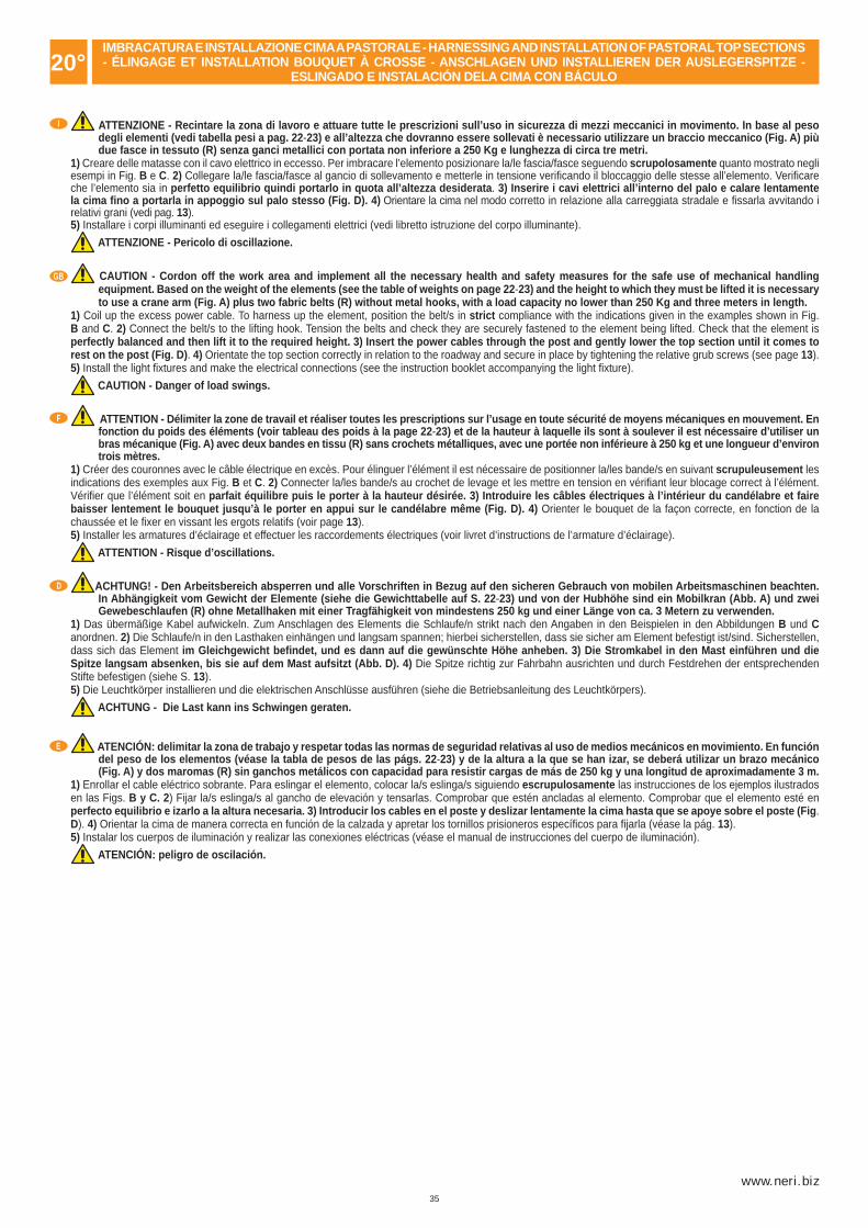
35
www.neri.biz
I
GB
F
D
20°
E
ATTENZIONE - Recintare la zona di lavoro e attuare tutte le prescrizioni sull’uso in sicurezza di mezzi meccanici in movimento. In base al peso degli elementi (vedi tabella pesi a pag. 22-23) e all’altezza che dovranno essere sollevati è necessario utilizzare un braccio meccanico (Fig. A) più due fasce in tessuto (R) senza ganci metallici con portata non inferiore a 250 Kg e lunghezza di circa tre metri.
1) Creare delle matasse con il cavo elettrico in eccesso. Per imbracare l’elemento posizionare la/le fascia/fasce seguendo scrupolosamente quanto mostrato negli esempi in Fig. B e C. 2) Collegare la/le fascia/fasce al gancio di sollevamento e metterle in tensione verifi cando il bloccaggio delle stesse all’elemento. Verifi care che l’elemento sia in perfetto equilibrio quindi portarlo in quota all’altezza desiderata. 3) Inserire i cavi elettrici all’interno del palo e calare lentamente la cima fi no a portarla in appoggio sul palo stesso (Fig. D). 4) Orientare la cima nel modo corretto in relazione alla carreggiata stradale e fi ssarla avvitando i relativi grani (vedi pag. 13).5) Installare i corpi illuminanti ed eseguire i collegamenti elettrici (vedi libretto istruzione del corpo illuminante).
ATTENZIONE - Pericolo di oscillazione.
CAUTION - Cordon off the work area and implement all the necessary health and safety measures for the safe use of mechanical handling equipment. Based on the weight of the elements (see the table of weights on page 22-23) and the height to which they must be lifted it is necessary to use a crane arm (Fig. A) plus two fabric belts (R) without metal hooks, with a load capacity no lower than 250 Kg and three meters in length.
1) Coil up the excess power cable. To harness up the element, position the belt/s in strict compliance with the indications given in the examples shown in Fig. B and C. 2) Connect the belt/s to the lifting hook. Tension the belts and check they are securely fastened to the element being lifted. Check that the element is perfectly balanced and then lift it to the required height. 3) Insert the power cables through the post and gently lower the top section until it comes to rest on the post (Fig. D). 4) Orientate the top section correctly in relation to the roadway and secure in place by tightening the relative grub screws (see page 13).5) Install the light fi xtures and make the electrical connections (see the instruction booklet accompanying the light fi xture).
CAUTION - Danger of load swings.
ATTENTION - Délimiter la zone de travail et réaliser toutes les prescriptions sur l’usage en toute sécurité de moyens mécaniques en mouvement. En fonction du poids des éléments (voir tableau des poids à la page 22-23) et de la hauteur à laquelle ils sont à soulever il est nécessaire d’utiliser un bras mécanique (Fig. A) avec deux bandes en tissu (R) sans crochets métalliques, avec une portée non inférieure à 250 kg et une longueur d’environ trois mètres.
1) Créer des couronnes avec le câble électrique en excès. Pour élinguer l’élément il est nécessaire de positionner la/les bande/s en suivant scrupuleusement les indications des exemples aux Fig. B et C. 2) Connecter la/les bande/s au crochet de levage et les mettre en tension en vérifi ant leur blocage correct à l’élément. Vérifi er que l’élément soit en parfait équilibre puis le porter à la hauteur désirée. 3) Introduire les câbles électriques à l’intérieur du candélabre et faire baisser lentement le bouquet jusqu’à le porter en appui sur le candélabre même (Fig. D). 4) Orienter le bouquet de la façon correcte, en fonction de la chaussée et le fi xer en vissant les ergots relatifs (voir page 13).5) Installer les armatures d’éclairage et effectuer les raccordements électriques (voir livret d’instructions de l’armature d’éclairage).
ATTENTION - Risque d’oscillations.
ACHTUNG! - Den Arbeitsbereich absperren und alle Vorschriften in Bezug auf den sicheren Gebrauch von mobilen Arbeitsmaschinen beachten. In Abhängigkeit vom Gewicht der Elemente (siehe die Gewichttabelle auf S. 22-23) und von der Hubhöhe sind ein Mobilkran (Abb. A) und zwei Gewebeschlaufen (R) ohne Metallhaken mit einer Tragfähigkeit von mindestens 250 kg und einer Länge von ca. 3 Metern zu verwenden.
1) Das übermäßige Kabel aufwickeln. Zum Anschlagen des Elements die Schlaufe/n strikt nach den Angaben in den Beispielen in den Abbildungen B und C anordnen. 2) Die Schlaufe/n in den Lasthaken einhängen und langsam spannen; hierbei sicherstellen, dass sie sicher am Element befestigt ist/sind. Sicherstellen, dass sich das Element im Gleichgewicht befi ndet, und es dann auf die gewünschte Höhe anheben. 3) Die Stromkabel in den Mast einführen und die Spitze langsam absenken, bis sie auf dem Mast aufsitzt (Abb. D). 4) Die Spitze richtig zur Fahrbahn ausrichten und durch Festdrehen der entsprechenden Stifte befestigen (siehe S. 13).5) Die Leuchtkörper installieren und die elektrischen Anschlüsse ausführen (siehe die Betriebsanleitung des Leuchtkörpers).
ACHTUNG - Die Last kann ins Schwingen geraten.
ATENCIÓN: delimitar la zona de trabajo y respetar todas las normas de seguridad relativas al uso de medios mecánicos en movimiento. En función del peso de los elementos (véase la tabla de pesos de las págs. 22-23) y de la altura a la que se han izar, se deberá utilizar un brazo mecánico (Fig. A) y dos maromas (R) sin ganchos metálicos con capacidad para resistir cargas de más de 250 kg y una longitud de aproximadamente 3 m.
1) Enrollar el cable eléctrico sobrante. Para eslingar el elemento, colocar la/s eslinga/s siguiendo escrupulosamente las instrucciones de los ejemplos ilustrados en las Figs. B y C. 2) Fijar la/s eslinga/s al gancho de elevación y tensarlas. Comprobar que estén ancladas al elemento. Comprobar que el elemento esté en perfecto equilibrio e izarlo a la altura necesaria. 3) Introducir los cables en el poste y deslizar lentamente la cima hasta que se apoye sobre el poste (Fig. D). 4) Orientar la cima de manera correcta en función de la calzada y apretar los tornillos prisioneros específi cos para fi jarla (véase la pág. 13).5) Instalar los cuerpos de iluminación y realizar las conexiones eléctricas (véase el manual de instrucciones del cuerpo de iluminación).
ATENCIÓN: peligro de oscilación.
IMBRACATURA E INSTALLAZIONE CIMA A PASTORALE - HARNESSING AND INSTALLATION OF PASTORAL TOP SECTIONS - ÉLINGAGE ET INSTALLATION BOUQUET À CROSSE - ANSCHLAGEN UND INSTALLIEREN DER AUSLEGERSPITZE -
ESLINGADO E INSTALACIÓN DELA CIMA CON BÁCULO
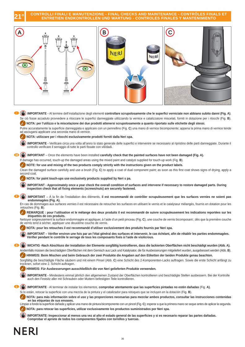
36
A B C
I
GB
F
D
E
IMPORTANTE - Al termine dell’installazione degli elementi controllare scrupolosamente che le superfi ci verniciate non abbiano subito danni (Fig. A).
Se ciò fosse accaduto provvedere a ritoccare le superfi ci danneggiate utilizzando la vernice e catalizzatore miscelati, forniti in dotazione per i ritocchi (Fig. B).
NOTA: per l’utilizzo e la miscelazione dei due prodotti attenersi scrupolosamente a quanto riportato sulle etichette degli stessi.
Pulire accuratamente la superfi cie danneggiata e applicare con un pennellino (Fig. C) una mano di vernice bicomponente; appena la prima mano di vernice tende ad asciugarsi applicare una seconda mano di vernice.
NOTA: utilizzare per i ritocchi esclusivamente prodotti forniti dalla Neri spa.
IMPORTANTE - Verifi care circa una volta all’anno lo stato generale delle superfi ci e intervenire se necessario al ripristino delle parti danneggiate. Durante il controllo verifi care il serraggio di tutte le parti fi ssate con viti/dadi.
IMPORTANT – Once the elements have been installed carefully check that the painted surfaces have not been damaged (Fig. A).
If damage has occurred, touch-up the damaged areas using the mixed paint and catalyst supplied for touch-up work (Fig. B).
NOTE: for use and mixing of the two products comply strictly with the instructions given on the product labels.
Clean the damaged surface carefully and use a brush (Fig. C) to apply a coat of dual component paint; as soon as this fi rst coat shows signs of drying, apply a second coat.
NOTA: for paint touch-ups use exclusively products supplied by Neri s pa.
IMPORTANT - Approximately once a year check the overall condition of surfaces and intervene if necessary to restore damaged parts. During inspection check that all fi xing elements (screws/nuts) are securely fastened.
IMPORTANT – À la fi n de l’installation des éléments, il est recommandé de contrôler scrupuleusement que les surfaces vernies ne soient pas endommagées (Fig. A).
En cas de dommages aux surfaces vernies il est nécessaire de retoucher les surfaces en utilisant le vernis et le catalyseur mélangés, fournis en dotation pour les retouches (Fig. B).
REMARQUE : pour l’utilisation et le mélange des deux produits il est recommandé de suivre scrupuleusement les indications reportées sur les étiquettes de ces produits.
Nettoyer soigneusement la surface endommagée et appliquer, à l’aide d’un petit pinceau (Fig. C), une couche de vernis bicomposant ; dès que la première couche de vernis tend à sécher, appliquer une deuxième couche de vernis.
NOTA: pour les retouches il est recommandé d’utiliser exclusivement des produits fournis par Neri spa.
IMPORTANT – Vérifi er environ une fois par an l’état général des surfaces et intervenir, le cas échéant, afi n de rétablir les parties endommagées. Vérifi er pendant le contrôle le serrage de tous les composants fi xés à l’aide de vis/écrous.
WICHTIG -Nach Abschluss der Installation der Elemente sorgfältig kontrollieren, dass die lackierten Oberfl ächen nicht beschädigt wurden (Abb. A).
Andernfalls müssen die beschädigten Oberfl ächen mit dem Gemisch aus Lack und Katalysator, die für Ausbesserungen mitgeliefert wurden, ausgebessert werden (Abb. B).
HINWEIS: Beim Mischen und beim Gebrauch der zwei Produkte die Angaben auf den Etiketten der beiden Produkte genau beachten.
Sorgfältig die beschädigte Fläche säubern und mit einem Pinsel (Abb. C) eine Schicht des 2-Komponenten-Lacks auftragen. Sowie die erste Schicht anfängt zu trocknen, sofort eine 2. Schicht auftragen.
HINWEIS: Für Ausbesserungen ausschließlich die von Neri gelieferten Produkte verwenden.
IMPORTANTE - Mindestens einmal jährlich den allgemeinen Zustand der Oberfl ächen kontrollieren und beschädigte Stellen ausbessern. Bei der Kontrolle auch den Festsitz aller mit Schrauben oder Muttern befestigten Teile kontrollieren.
IMPORTANTE - Al terminar de instalar los elementos, comprobar atentamente que las superfi cies pintadas no estén dañadas (Fig. A).
Si lo están, retocar la superfi cie con una mezcla de la pintura y el catalizador para retoques que se incluyen en la dotación (Fig. B).
NOTA: para más información sobre el uso y las proporciones necesarias para mezclar ambos productos, consultar las instrucciones contenidas en las etiquetas de sus envases.
Limpiar a fondo la superfi cie dañada y aplicar una mano de pintura bicomponente con un pincel (Fig. C); esperar a que la primera mano se seque antes de aplicar la segunda.
NOTA: para retocar las superfi cies, utilizar exclusivamente los productos suministrados por Neri spa.
IMPORTANTE: Inspeccionar al menos una vez al año el estado general de las superfi cies y si es necesario reparar las partes dañadas. Comprobar el apriete de todos los componentes fi jados con tornillos y tuercas.
21° CONTROLLI FINALI E MANUTENZIONE - FINAL CHECKS AND MAINTENANCE - CONTRÔLES FINALS ET ENTRETIEN ENDKONTROLLEN UND WARTUNG - CONTROLES FINALES Y MANTENIMIENTO


![Pierangela Croce Da Villa - openstarts.units.it · delle problematiche che suscita la localizzazione del Portus Reatinum pliniano, ... emisferica, con iscrizione sul plinto:[---]](https://static.fdocumenti.com/doc/165x107/5c67a54c09d3f2c85f8c3508/pierangela-croce-da-villa-delle-problematiche-che-suscita-la-localizzazione.jpg)


![Lezione 27 Ponti (Pile).ppt [modalità compatibilità] Ponti 2014-15/Lezione 27... · costituita da pila, plinto e pali.](https://static.fdocumenti.com/doc/165x107/5c65c41209d3f2826e8d1608/lezione-27-ponti-pileppt-modalita-compatibilita-ponti-2014-15lezione-27.jpg)