MOTORI ASINCRONI TRIFASI SERIE T 56 - interempresas.net · Electro Adda Group CT-TEG - Rev 1 -...
58
MOTORI ASINCRONI TRIFASI SERIE T 56 ÷ 132 SERIE EG 132 ÷ 355 kW 0.05 ÷ 315 THREE-PHASE ASYNCHRONOUS MOTORS T SERIES 56 ÷ 132 EG SERIES 132 ÷ 355 Kw 0.05 ÷ 315 CT-TEG—Rev 1 –12-2014
Transcript of MOTORI ASINCRONI TRIFASI SERIE T 56 - interempresas.net · Electro Adda Group CT-TEG - Rev 1 -...
MOTORI ASINCRONI TRIFASI
SERIE T 56 ÷ 132
SERIE EG 132 ÷ 355 kW 0.05 ÷ 315
THREE-PHASE ASYNCHRONOUS MOTORS
T SERIES 56 ÷ 132
EG SERIES 132 ÷ 355 Kw 0.05 ÷ 315
CT-TEG—Rev 1 –12-2014

Electro Adda Group CT-TEG - Rev 1 - 12-14
2
Certificati Certificates
Le caratteristiche tecniche, le dimensioni ed ogni altro dato di questo catalogo non sono impegnative.
ELECTRO ADDA SpA si riserva il diritto di cambiarle in qualsiasi momento e senza preavviso
Technical features, dimensions, as well as any othe r data in this catalogue are not binding. ELECTRO ADDA SpA reserves the right to change them at any time without giving any previous notice
Electro Adda Group CT-TEG - Rev 1 - 12-14
3
MOTORI ASINCRONI TRIFASI Serie T - Grandezze 63÷132 Serie EG - Grandezze 132÷355
ASYNCHRONOUS THREE-PHASE MOTORS T line - Frame sizes 63÷132
T line - Frame sizes132÷355
Indice Index
Nuove normative riguardanti l’efficienza Caratteristiche generali Norme, Unificazioni Forme costruttive Grado di protezione Particolari costruttivi Raffreddamento Cuscinetti per motori standard Carichi ammessi sui cuscinetti Cuscinetti per carichi radiali elevati Intervalli di lubrificazione Targhe Scatola morsetti e morsettiera Gabbia di rotore Isolamento, avvolgimento Potenze e dati tecnici Tensioni di alimentazione e collegamenti Oscillazioni di tensione e frequenza Funzionamento a 60 Hz Squilibrio di tensione Servizi Declassamenti Sovraccarichi Avviamenti Rumorosità Vibrazioni Protezioni termiche Scaldiglie anticondensa Verniciatura
4 7 8 9 10 10 11 12 13 18 20 21 21 21 21 22 22 22 23 24 24 25 25 25 26 26 26 27 27
New standards concerning efficiency General features Standards and Standardizations Mountings and positions Degree of protection Construction Cooling Bearings for standard motors Permissible load on the bearing Bearings for high radial loads Lubrication intervals Rating plates Terminal box and block Rotor cage Insulation, winding Ratings and technical data Supply voltage and connections Voltage and frequency variations Operation at 60 Hz frequency Unbalanced voltage Duties Deratings Overloads Starting Noise Vibrations Thermal protections Anticondensation heaters Paintings
4 7 8 9 10 10 11 12 13 18 20 21 21 21 21 22 22 22 23 24 24 25 25 25 26 26 26 27 27
Caratteristiche tecniche Classe di efficienza IE1 Classe di Efficienza IE2 Classe di Efficienza IE3 Doppia polarità
Alimentazione da inverter Velocità massima Funzionamento a potenza aumentata
28 32 35 38 40 42 43
Technical features IE1 Efficiency class IE2 Efficiency class IE3 Efficiency class Double polarity Inverter supply Maximun speed Increased power operating
28 32 35 38 40 42 43
Dimensioni d’ingombro Motori autoventilati (IC 411) Ventilatori ausiliari (IC416) Dimensioni (IC416)
43 45 54 55
Overall dimensions Self ventilating motors (IC411) Assisted ventilation (IC416) Overall dimensions IC416
43 45 54 55
Electro Adda Group CT-TEG - Rev 1 - 12-14
4
Nuove normative riguardanti l’efficienza New standards concerning efficiency
La Commissione IEC ha introdotto due nuove normative riguardanti l’efficienza energetica dei motori: - IEC 60034-2-1 che specifica i criteri che
definiscono i metodi di prova relativi al calcolo dell’efficienza
- IEC 60034-30 che definisce le nuove classi di efficienza dei motori.
IEC 60034-2-1; 2007
Il nuovo standard IEC 60034-2-1, entrato in vigore a settembre 2007, introduce nuove regole relative ai metodi di prova da utilizzare per la determinazione delle perdite e dell’ efficienza. Ci sono due modalità di determinazione dell'efficienza: il metodo diretto ed il metodo indiretto. Per il metodo indiretto la nuova norma specifica i seguenti parametri: - la temperatura di riferimento - tre opzioni per la determinazione delle perdite di carico supplementari: misurazione, stima e calcolo matematico. Il nuovo standard ELECTRO ADDA utilizza il metodo indiretto di calcolo, e le perdite di carico supplementari determinate dalla misurazione. I valori di efficienza derivati sono diversi da quelli risultanti dal precedente standard di prova IEC 60034-2-1996. E’ da notare che i valori di efficienza sono comparabili solo se misurati con lo stesso metodo. La documentazione del motore deve indicare il metodo utilizzato. I valori di rendimento nelle pagine dei dati tecnici di questo catalogo, sono dati secondo entrambe i metodi di calcolo vecchio e nuovo. Di seguito sono mostrate le differenze tra vecchio e nuovo standard. Vecchio metodo di prova standard EN/IEC60034-2-1996: Metodo diretto Metodo indiretto: • PLL (perdite addizionali) stimato al 0.5 % della potenza in ingresso a carico nominale. Le perdite nello statore e nel rotore sono determinate a 95°C. Nuovo metodo di prova standard EN/IEC 60034-2-1-2007: Metodo diretto Metodo indiretto: - Misurazione: PLL calcolato da prove di carico; - Stima: PLL dal 2,5% al 1,0% di potenza in
ingresso a carico nominale compresa tra 0,1 kW e 1000 kW;
- Matematica: metodo alternativo indiretto per il calcolo matematico del PLL. Le perdite nello statore e nel rotore sono determinate a 25°C + temperatura reale misurata.
The IEC Commission introduced two new standards concerning energy efficient motors. - IEC/EN 60034-2-1 specifies new rules concerning
efficiency testing methods; - IEC 60034-30 defines new efficiency classes for
motors. IEC/EN 60034-2-1; 2007
The new standard IEC/EN 60034-2-1, which came into force September 2007, introduces new rules concerning the testing methods to be used for determining losses and efficiency. It offers two ways of determining the efficiency; direct method and indirect method. The new standard specifies following parameters for determining the efficiency according to indirect method: - reference temperature - three options for determining additional load losses: measurement, estimation and mathematical. The new ELECTRO ADDA standard uses the indirect calculation method, additional load losses are determined from measuring. The resulting efficiency values differ from those obtained under the previous IEC 60034-2-1996 testing standard. It must be noted that efficiency values are only comparable if they are measured using the same method. The motor documentation must state which method is used. The efficiency values on the technical data pages in this catalogue are given according to both new and old calculation methods. The table below shows the differences between old and new standard. Old efficiency testing standard EN/IEC 60034-2-1996 Direct method Indirect method: • PLL (= additional losses) estimated at 0.5 % of input power at rated load. Winding losses in stator and rotor determined at 95°C. New efficiency testing standard IEC/EN 60034-2-1-2007 Direct method Indirect method: - Measurement; PLL calculated from load tests - Estimation; PLL at 2.5% - 1.0% of input power at
rated load between 0.1 kW and 1000 kW
- Mathematical calculation; alternative indirect method with mathematical calculation of PLL.Winding losses in stator and rotor determined at 25°C + actual measured temperature.
Electro Adda Group CT-TEG - Rev 1 - 12-14
5
IEC 60034-30; 2008 La norma IEC 60034-30 ottobre 2008 definisce tre classi di efficienza IE (International Efficiency) per motori asincroni trifasi a gabbia e singola velocità. - IE1 = Efficienza standard (livelli di efficienza più o
meno equivalente a EFF2 in Europa al giorno d'oggi)
- IE2 = Alta efficienza (livelli di efficienza più o meno equivalente a EFF1 in Europa oggi e identico a EPAct in USA per 60 Hz)
- IE3 = Efficienza Premium (nuova classe di efficienza in Europa oggi e identico a "NEMA Premium" negli Stati Uniti per 60 Hz)
- La norma IEC 60034-30 copre quasi tutti i tipi di motori (standard, zona pericolosa, marina, autofrenanti): • Singole velocità, trifase, 50 e 60 Hz • 2, 4 o 6 poli • Potenza nominale in uscita da 0.75 a 375 kW • Tensione nominale Un fino a 1000 V • Tipo di servizio S1 (funzionamento continuo) o S3
(servizio intermittente periodico), con un fattore nominale di intermittenza dell’80% o superiore In grado di funzionare direttamente in linea
I seguenti motori sono esclusi dalla IEC 60034-30: - Motori per il funzionamento con convertitori - Motori integrati in una macchina (per es. pompe, ventilatori o compressori) che non possono essere provati separatamente da essa.
IEC 60034-30; 2008 IEC 60034-30: October 2008 defines three IE (International Efficiency) efficiency classes of single speed, three phase, cage induction motors. - IE1 = Standard efficiency (efficiency levels
roughly equivalent to EFF2 in Europe nowadays)
- IE2 = High efficiency (efficiency levels roughly equivalent to EFF1 in Europe nowadays and identical to EPAct in USA for 60 Hz)
- IE3 = Premium efficiency (new efficiency class in Europe nowadays and identical to "NEMA Premium" in the USA for 60Hz)
IEC 60034-30 covers almost all motors (for example standard, hazardous area, marine, brake motors): • Single-speed, three-phase, 50 Hz and 60 Hz • 2, 4 or 6-pole • Rated output from 0.75 to 375 kW • Rated voltage UN up to 1000 V • Duty type S1 (continuous duty) or S3 (intermittent
periodic duty) with a rated cyclic duration factor of 80% or higher capable of operating direct online
Following motors are excluded from IEC 60034-30: – Motors made solely for converter operation – Motors completely integrated into a machine (for example, pump, fan and compressor) that cannot be tested separately from the machine
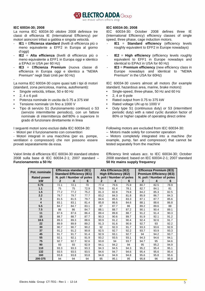
Valori limite di efficienza IEC 60034-30 standard ottobre 2008 sulla base di IEC 60034-2-1; 2007 standard – Funzionamento a 50 Hz
Efficiency limit values acc. to IEC 60034-30; October 2008 standard; based on IEC 60034-2-1; 2007 standard 50 Hz mains supply frequency
Pot. nominale Efficenza standard (IE1) Standard Efficiency (IE1)
Alta Efficienza (IE2) High Efficiency (IE2)
Efficenza Premium (IE3) Premium Efficiency (IE3)
Rated power N. poli / Number of poles N. poli / Number of poles N. poli / Number of poles kW 2 4 6 2 4 6 2 4 6 0.75 72.1 72.1 70 77.4 79.6 75.9 80.7 82.5 78.9 1.1 75 75 72.9 79.6 81.4 78.1 82.7 84.1 81 1.5 77.2 77.2 75.2 81.3 82.8 79.8 84.2 85.3 82.5 2.2 79.7 79.7 77.7 83.2 84.3 81.8 85.9 86.7 84.3 3 81.5 81.5 79.7 84.6 85.5 83.3 87.1 87.7 85.6 4 83.1 83.1 81.4 85.8 86.6 84.6 88.1 88.6 86.8
5.5 84.7 84.7 83.1 87 87.7 86 89.2 89.6 88 7.5 86 86 84.7 88.1 88.7 87.2 90.1 90.4 89.1 11 87.6 87.6 86.4 89.4 89.8 88.7 91.2 91.4 90.3 15 88.7 88.7 87.7 90.3 90.6 89.7 91.9 92.1 91.2 18.5 89.3 89.3 88.6 90.9 91.2 90.4 92.4 92.6 91.7 22 89.9 89.9 89.2 91.3 91.6 90.9 92.7 93 92.2 30 90.7 90.7 90.2 92 92.3 91.7 93.3 93.6 92.9 37 91.2 91.2 90.8 92.5 92.7 92.2 93.7 93.9 93.3 45 91.7 91.7 91.4 92.9 93.1 92.7 94 94.2 93.7 55 92.1 92.1 91.9 93.2 93.5 93.1 94.3 94.6 94.1 75 92.7 92.7 92.6 93.8 94 93.7 94.7 95 94.6 90 93 93 92.9 94.1 94.2 94 95 95.2 94.9 110 93.3 93.3 93.3 94.3 94.5 94.3 95.2 95.4 95.1 132 93.5 93.5 93.5 94.6 94.7 94.6 95.4 95.6 95.4 160 93.8 93.8 93.8 94.8 94.9 94.8 95.6 95.8 95.6
200-375 94 94 94 95 95.1 95 95.8 96 95.8
Electro Adda Group CT-TEG - Rev 1 - 12-14
6
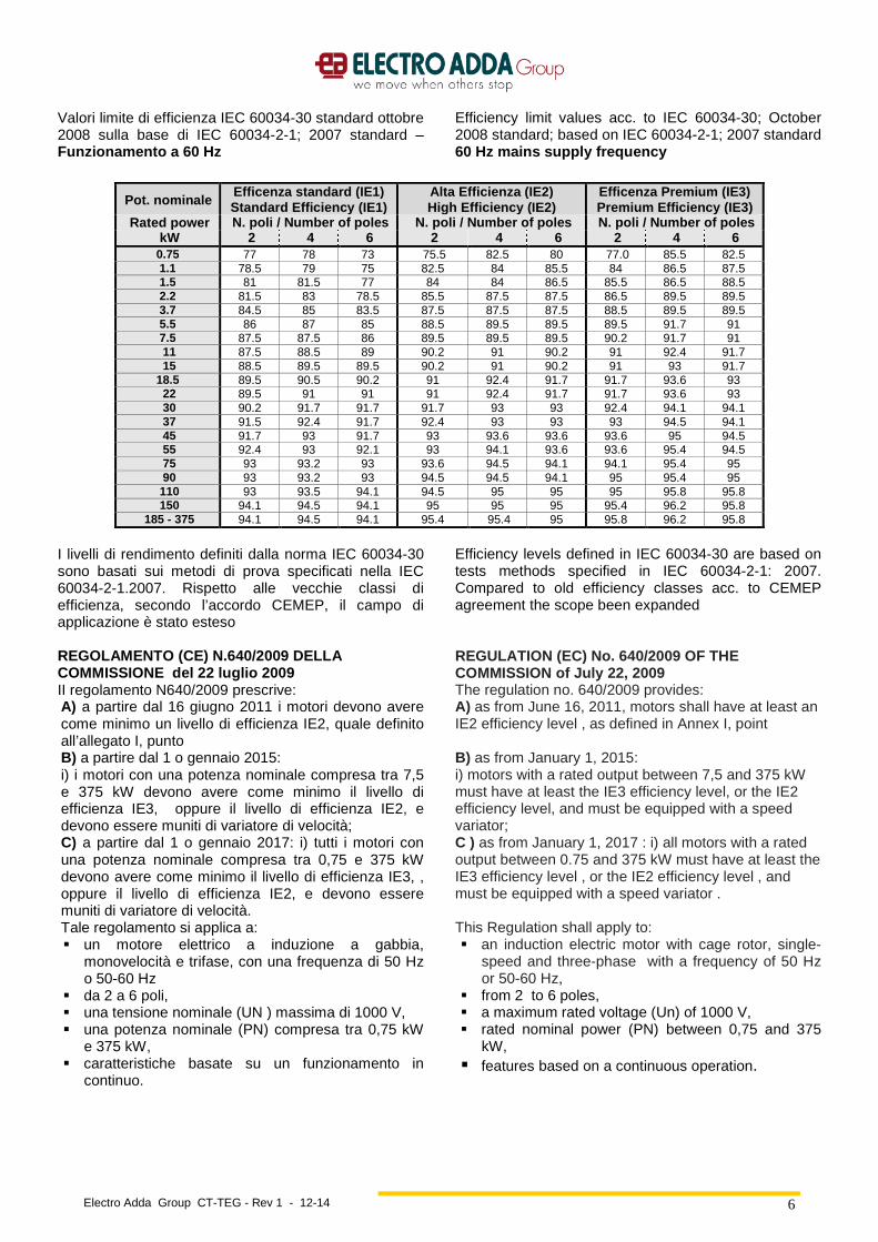
Valori limite di efficienza IEC 60034-30 standard ottobre 2008 sulla base di IEC 60034-2-1; 2007 standard – Funzionamento a 60 Hz
Efficiency limit values acc. to IEC 60034-30; October 2008 standard; based on IEC 60034-2-1; 2007 standard 60 Hz mains supply frequency
Pot. nominale Efficenza standard (IE1) Standard Efficiency (IE1)
Alta Efficienza (IE2) High Efficiency (IE2)
Efficenza Premium ( IE3) Premium Efficiency (IE3)
Rated power N. poli / Number of poles N. poli / Number of poles N. poli / Number of poles kW 2 4 6 2 4 6 2 4 6 0.75 77 78 73 75.5 82.5 80 77.0 85.5 82.5 1.1 78.5 79 75 82.5 84 85.5 84 86.5 87.5 1.5 81 81.5 77 84 84 86.5 85.5 86.5 88.5 2.2 81.5 83 78.5 85.5 87.5 87.5 86.5 89.5 89.5 3.7 84.5 85 83.5 87.5 87.5 87.5 88.5 89.5 89.5 5.5 86 87 85 88.5 89.5 89.5 89.5 91.7 91 7.5 87.5 87.5 86 89.5 89.5 89.5 90.2 91.7 91 11 87.5 88.5 89 90.2 91 90.2 91 92.4 91.7 15 88.5 89.5 89.5 90.2 91 90.2 91 93 91.7 18.5 89.5 90.5 90.2 91 92.4 91.7 91.7 93.6 93 22 89.5 91 91 91 92.4 91.7 91.7 93.6 93 30 90.2 91.7 91.7 91.7 93 93 92.4 94.1 94.1 37 91.5 92.4 91.7 92.4 93 93 93 94.5 94.1 45 91.7 93 91.7 93 93.6 93.6 93.6 95 94.5 55 92.4 93 92.1 93 94.1 93.6 93.6 95.4 94.5 75 93 93.2 93 93.6 94.5 94.1 94.1 95.4 95 90 93 93.2 93 94.5 94.5 94.1 95 95.4 95 110 93 93.5 94.1 94.5 95 95 95 95.8 95.8 150 94.1 94.5 94.1 95 95 95 95.4 96.2 95.8
185 - 375 94.1 94.5 94.1 95.4 95.4 95 95.8 96.2 95.8
I livelli di rendimento definiti dalla norma IEC 60034-30 sono basati sui metodi di prova specificati nella IEC 60034-2-1.2007. Rispetto alle vecchie classi di efficienza, secondo l’accordo CEMEP, il campo di applicazione è stato esteso
Efficiency levels defined in IEC 60034-30 are based on tests methods specified in IEC 60034-2-1: 2007. Compared to old efficiency classes acc. to CEMEP agreement the scope been expanded
REGOLAMENTO (CE) N.640/2009 DELLA COMMISSIONE del 22 luglio 2009 II regolamento N640/2009 prescrive: A) a partire dal 16 giugno 2011 i motori devono avere come minimo un livello di efficienza IE2, quale definito all’allegato I, punto B) a partire dal 1 o gennaio 2015: i) i motori con una potenza nominale compresa tra 7,5 e 375 kW devono avere come minimo il livello di efficienza IE3, oppure il livello di efficienza IE2, e devono essere muniti di variatore di velocità; C) a partire dal 1 o gennaio 2017: i) tutti i motori con una potenza nominale compresa tra 0,75 e 375 kW devono avere come minimo il livello di efficienza IE3, , oppure il livello di efficienza IE2, e devono essere muniti di variatore di velocità. Tale regolamento si applica a: � un motore elettrico a induzione a gabbia,
monovelocità e trifase, con una frequenza di 50 Hz o 50-60 Hz
� da 2 a 6 poli, � una tensione nominale (UN ) massima di 1000 V, � una potenza nominale (PN) compresa tra 0,75 kW
e 375 kW, � caratteristiche basate su un funzionamento in
continuo.
REGULATION (EC) No. 640/2009 OF THE COMMISSION of July 22, 2009 The regulation no. 640/2009 provides: A) as from June 16, 2011, motors shall have at least an IE2 efficiency level , as defined in Annex I, point B) as from January 1, 2015: i) motors with a rated output between 7,5 and 375 kW must have at least the IE3 efficiency level, or the IE2 efficiency level, and must be equipped with a speed variator; C ) as from January 1, 2017 : i) all motors with a rated output between 0.75 and 375 kW must have at least the IE3 efficiency level , or the IE2 efficiency level , and must be equipped with a speed variator . This Regulation shall apply to: � an induction electric motor with cage rotor, single-
speed and three-phase with a frequency of 50 Hz or 50-60 Hz,
� from 2 to 6 poles, � a maximum rated voltage (Un) of 1000 V, � rated nominal power (PN) between 0,75 and 375
kW, � features based on a continuous operation.
Electro Adda Group CT-TEG - Rev 1 - 12-14
7
Caratteristiche generali General features
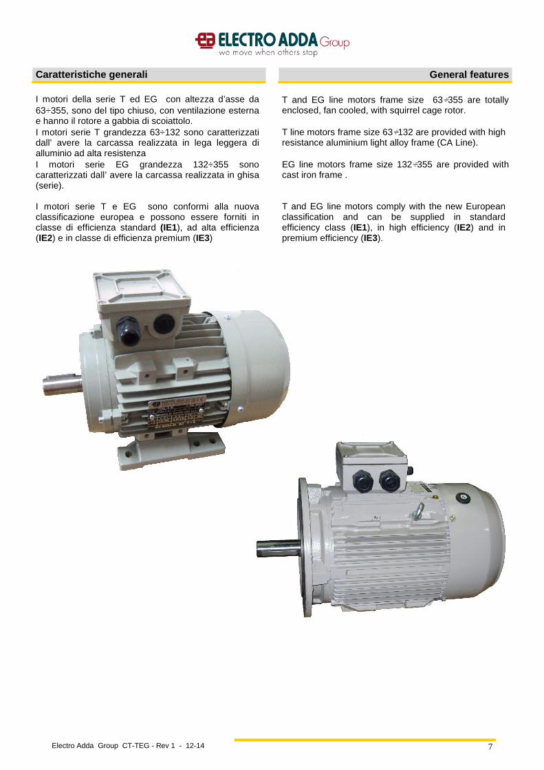
I motori della serie T ed EG con altezza d’asse da 63÷355, sono del tipo chiuso, con ventilazione esterna e hanno il rotore a gabbia di scoiattolo. I motori serie T grandezza 63÷132 sono caratterizzati dall’ avere la carcassa realizzata in lega leggera di alluminio ad alta resistenza I motori serie EG grandezza 132÷355 sono caratterizzati dall’ avere la carcassa realizzata in ghisa (serie). I motori serie T e EG sono conformi alla nuova classificazione europea e possono essere forniti in classe di efficienza standard (IE1), ad alta efficienza (IE2) e in classe di efficienza premium (IE3)
T and EG line motors frame size 63÷355 are totally enclosed, fan cooled, with squirrel cage rotor. T line motors frame size 63÷132 are provided with high resistance aluminium light alloy frame (CA Line). EG line motors frame size 132÷355 are provided with cast iron frame . T and EG line motors comply with the new European classification and can be supplied in standard efficiency class (IE1), in high efficiency (IE2) and in premium efficiency (IE3).

Electro Adda Group CT-TEG - Rev 1 - 12-14
8
Norme, Unificazioni Standards and standardizations
I motori del presente catalogo sono conformi alle seguenti Norme e Direttive:
Motors described in this cataogue comply with the following Standards and Directives:
CEI IEC Titolo Title
EN 60034-1 60034-1 Caratteristiche nominali e di funzionamento
Rating and performances
EN 60034-2 60034-2 Metodi di determinazione delle perdite e rendimento
Methods for detemining losses and efficiency
EN 60034-5 60034-5 Classificazione dei gradi di protezione (codice IP)
Classification of the degrees of protection (IP code)
EN 60034-6 60034-6 Metodi di raffreddamento (codice IC) Methods of cooling (IC code)
EN 60034-7 60034-7 Tipi di costruzione, forme costruttive e posizione scatola morsetti (codice IM)
Types of construction, mounting arrangements and terminal box position (IM code)
EN 60034-8 60034-8 Marcatura dei terminali e senso di rotazione
Terminal markings and direction of rotation
EN 60034-9 60034-9 Limiti di rumore Noise limits
60034-11 60034-11 Protezioni termiche a bordo macchina Built-in thermal protections
EN 60034-12 60034-12 Prestazioni elettriche delle macchine elettriche rotanti all’avviamento
Starting performance of rotating electrical machines
EN 60034-14 60034-14 Vibrazioni meccaniche delle macchine rotanti
Mechanical vibrations of rotating machines
IEC 60034-30 Ed. 1 Classe di efficienza di motori asincroni trifase con rotore a gabbia a singola velocità (codice IE)
Efficiency classes of single-speed, three-phase, cage-induction motors (IE code)
EN 50347 60072-1
60072-2
Dimensioni e potenze delle macchine rotanti
Dimensions and outputs for rotating machines
16-8 1293 Marcatura delle apparecchiature elettriche
Marking of electrical devices
IEC TS 60034-25
Guida per il progetto e le prestazioni di motori ca specificatamente progettati per alimentazione da inverter – Specifica tecnica
Guidance for the design and performance of a.c. motors specifically designed for converter supply –Technical specification
IEC TS 60034-18-41
Qualificazione e prove di tipo dei sistemi d’isolamento di tipo I utilizzati nelle macchine rotanti alimentate da inverter-Specifica tecnica
Qualification and type tests for type I electrical insulation systems used in rotating electrical machines fed from voltage converters-Technical specification
UNI ISO 2768/1-2 Tolleranze generali General tolerances
UNI 321 Estremità d'albero Shaft end
73/23/EEC Direttiva bassa tensione Low voltage directive
89/336/EEC (EMC) Direttiva compatibilità elettromagnetica Electromagnetic compatibility directive
2006/42/CE Direttiva macchine Machine directive
Le unificazioni UNEL concordano con le norme internazionali IEC, pubblicazione 72, e relativo Emendamento N° 1.
The UNEL standardizations are in accordance with the IEC international standards publication 72 and relative Amendment No. 1.
I motori possono essere realizzati anche per applicazioni a bordo di navi; in tal caso sono inoltre conformi alle prescrizioni emesse dagli enti di classificazione: Registro Italiano Navale Lloyds Register of Shipping Bureau Veritas American Bureau of Shipping Det Norske Veritas
Motors can also be manufactured for applications on shipboard; in this case they are also in compliance with the prescriptions issued by the following Classification Bodies: Registro Italiano Navale Lloyds Register of Shipping Bureau Veritas American Bureau of Shipping Det Norske Veritas
Electro Adda Group CT-TEG - Rev 1 - 12-14
9
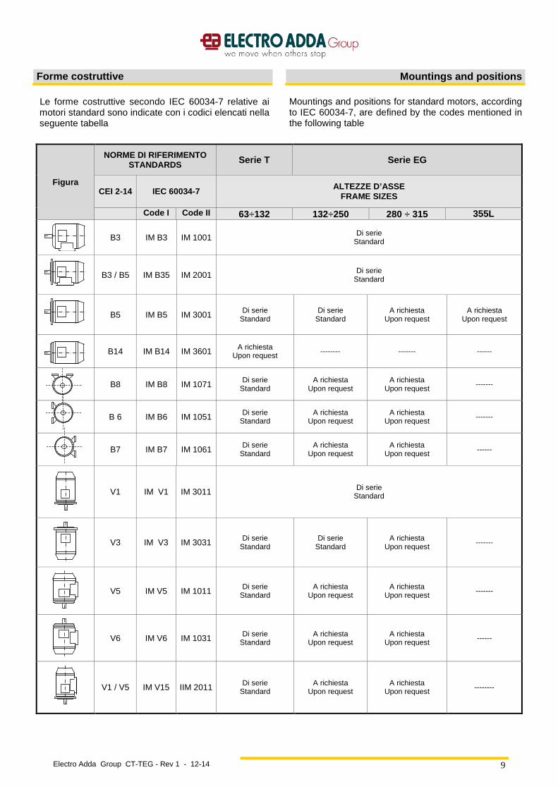
Forme costruttive Mountings and positions
Le forme costruttive secondo IEC 60034-7 relative ai motori standard sono indicate con i codici elencati nella seguente tabella
Mountings and positions for standard motors, according to IEC 60034-7, are defined by the codes mentioned in the following table
Figura
NORME DI RIFERIMENTO STANDARDS Serie T Serie EG
CEI 2-14 IEC 60034-7 ALTEZZE D’ASSE FRAME SIZES
Code I Code II 63÷132 132÷250 280 ÷ 315 355L
B3 IM B3 IM 1001 Di serie Standard
B3 / B5 IM B35 IM 2001 Di serie
Standard
B5 IM B5 IM 3001 Di serie
Standard Di serie
Standard A richiesta
Upon request A richiesta
Upon request
B14 IM B14 IM 3601 A richiesta Upon request -------- ------- ------
B8 IM B8 IM 1071 Di serie
Standard A richiesta
Upon request A richiesta
Upon request -------
B 6 IM B6 IM 1051 Di serie
Standard A richiesta
Upon request A richiesta
Upon request -------
B7 IM B7 IM 1061 Di serie Standard
A richiesta Upon request
A richiesta Upon request ------
V1 IM V1 IM 3011 Di serie Standard
V3 IM V3 IM 3031 Di serie Standard
Di serie Standard
A richiesta Upon request
-------
V5 IM V5 IM 1011 Di serie Standard
A richiesta Upon request
A richiesta Upon request
-------
V6 IM V6 IM 1031 Di serie Standard
A richiesta Upon request
A richiesta Upon request ------
V1 / V5 IM V15 IIM 2011 Di serie Standard
A richiesta Upon request
A richiesta Upon request --------
Electro Adda Group CT-TEG - Rev 1 - 12-14
10
Grado di protezione Degrees of protection
I motori sono in accordo con le Norme IEC 60034-5, hanno i seguenti gradi di protezione: IP 55 (di serie). Motori chiusi con ventilazione esterna protetti alla penetrazione di polvere e getti d’acqua provenienti da ogni direzione IP 56 (a richiesta). Motori stagni protetti alla penetrazione della polvere e contro le ondate per funzionamento sopracoperta. La ventola esterna è coperta da una calotta avente grado di protezione lP 20 (cioè è protetta contro l’accesso involontario delle dita). A richiesta, i motori previsti per l’installazione con asse verticale con albero verso il basso, vengono forniti con il tettuccio di protezione. La scatola morsettiera ha il grado di protezione IP 55 o IP 56.
Motors, according to IEC 60034-5 Standards, have the following protection degrees IP 55 (standard) totally enclosed motors, fan cooled, protected against penetration of dust and water splashes coming from any direction IP 56 (upon request) totally enclosed motors, protected against dust penetration and against sea waves, for use on deck. The external fan is covered by a fan cover with IP 20 protection degree (accidental contact of fingers is avoided). Upon request, motors for vertical mounting, can be supplied with rain cowl. The terminal box has IP 55 or IP56 protection degree.
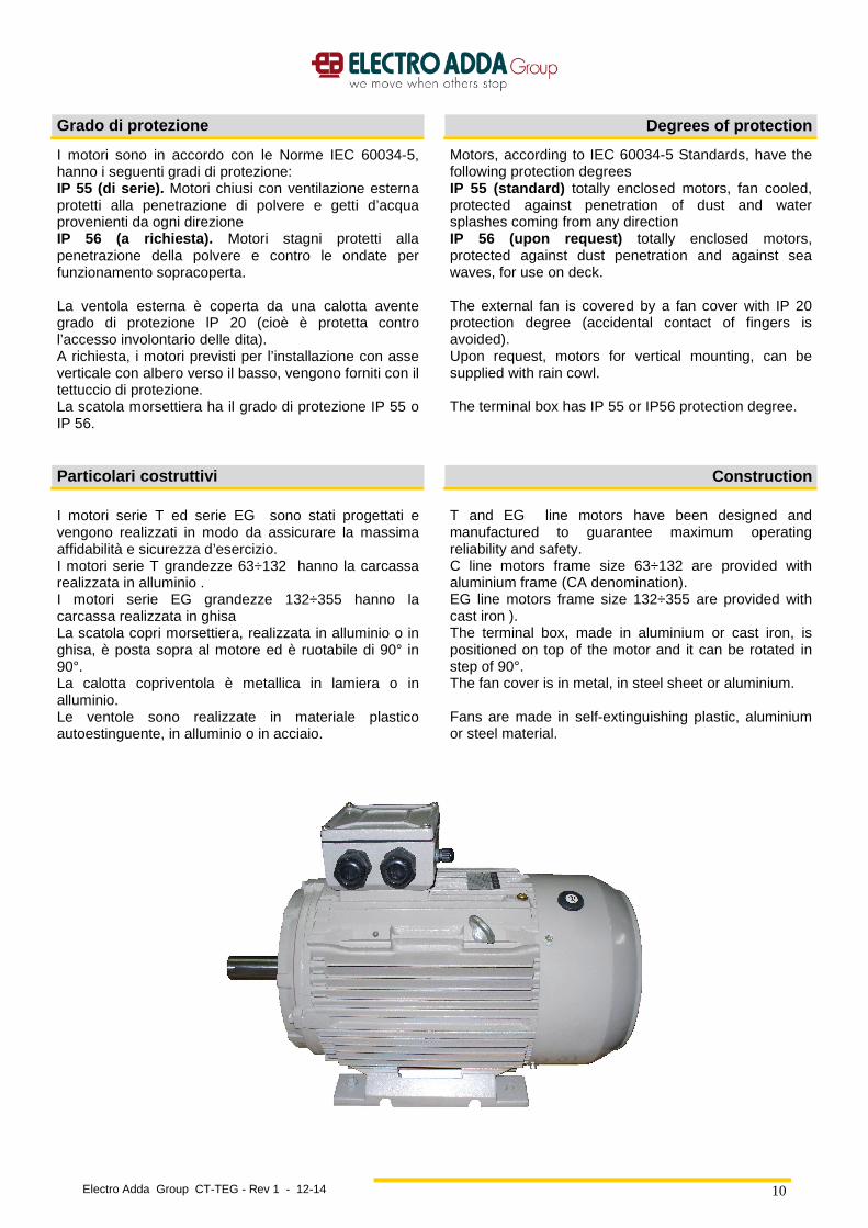
Particolari costruttivi Construction
I motori serie T ed serie EG sono stati progettati e vengono realizzati in modo da assicurare la massima affidabilità e sicurezza d’esercizio. I motori serie T grandezze 63÷132 hanno la carcassa realizzata in alluminio . I motori serie EG grandezze 132÷355 hanno la carcassa realizzata in ghisa La scatola copri morsettiera, realizzata in alluminio o in ghisa, è posta sopra al motore ed è ruotabile di 90° in 90°. La calotta copriventola è metallica in lamiera o in alluminio. Le ventole sono realizzate in materiale plastico autoestinguente, in alluminio o in acciaio.
T and EG line motors have been designed and manufactured to guarantee maximum operating reliability and safety. C line motors frame size 63÷132 are provided with aluminium frame (CA denomination). EG line motors frame size 132÷355 are provided with cast iron ). The terminal box, made in aluminium or cast iron, is positioned on top of the motor and it can be rotated in step of 90°. The fan cover is in metal, in steel sheet or aluminium. Fans are made in self-extinguishing plastic, aluminium or steel material.
Electro Adda Group CT-TEG - Rev 1 - 12-14
11
Raffreddamento Cooling
La definizione del metodo di raffreddamento è data dal codice IC (International Cooling), in accordo alla IEC 60034-6.
The designation of cooling method is given by the IC (International Cooling) code, according to IEC60034-6
Codice I (Semplificato) IC 4 1 1 Code I (Simplified) IC 4 1 1 Disposizione del circuito
Circuit Arrangement
Metodi di circolazione del fluido di raffreddamento primario.
Method of fluid circulation for the secondary cooling fluid.
Metodi di circolazione del fluido di raffreddamento secondario.
Method of fluid circulation for the primary cooling fluid.
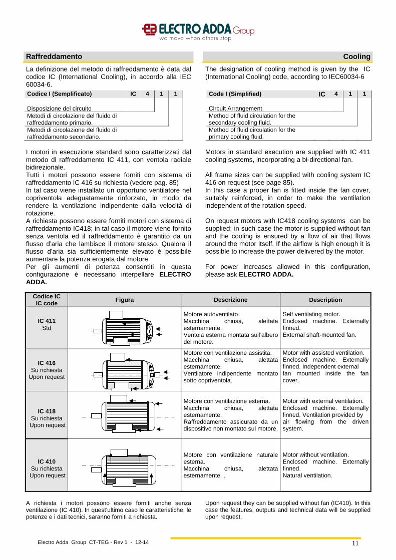
I motori in esecuzione standard sono caratterizzati dal metodo di raffreddamento IC 411, con ventola radiale bidirezionale. Tutti i motori possono essere forniti con sistema di raffreddamento IC 416 su richiesta (vedere pag. 85) In tal caso viene installato un opportuno ventilatore nel copriventola adeguatamente rinforzato, in modo da rendere la ventilazione indipendente dalla velocità di rotazione. A richiesta possono essere forniti motori con sistema di raffreddamento IC418; in tal caso il motore viene fornito senza ventola ed il raffreddamento è garantito da un flusso d’aria che lambisce il motore stesso. Qualora il flusso d’aria sia sufficientemente elevato è possibile aumentare la potenza erogata dal motore. Per gli aumenti di potenza consentiti in questa configurazione è necessario interpellare ELECTRO ADDA.
Motors in standard execution are supplied with IC 411 cooling systems, incorporating a bi-directional fan. All frame sizes can be supplied with cooling system IC 416 on request (see page 85). In this case a proper fan is fitted inside the fan cover, suitably reinforced, in order to make the ventilation independent of the rotation speed. On request motors with IC418 cooling systems can be supplied; in such case the motor is supplied without fan and the cooling is ensured by a flow of air that flows around the motor itself. If the airflow is high enough it is possible to increase the power delivered by the motor. For power increases allowed in this configuration, please ask ELECTRO ADDA.
Codice IC IC code Figura Descrizione Description
IC 411 Std
Motore autoventilato Macchina chiusa, alettata esternamente. Ventola esterna montata sull’albero del motore.
Self ventilating motor. Enclosed machine. Externally finned. External shaft-mounted fan.
IC 416 Su richiesta
Upon request
Motore con ventilazione assistita. Macchina chiusa, alettata esternamente. Ventilatore indipendente montato sotto copriventola.
Motor with assisted ventilation. Enclosed machine. Externally finned. Independent external fan mounted inside the fan cover.
IC 418
Su richiesta Upon request
Motore con ventilazione esterna. Macchina chiusa, alettata esternamente. Raffreddamento assicurato da un dispositivo non montato sul motore.
Motor with external ventilation. Enclosed machine. Externally finned. Ventilation provided by air flowing from the driven system.
IC 410
Su richiesta Upon request
Motore con ventilazione naturale esterna. Macchina chiusa, alettata esternamente. .
Motor without ventilation. Enclosed machine. Externally finned. Natural ventilation.
A richiesta i motori possono essere forniti anche senza ventilazione (IC 410). In quest’ultimo caso le caratteristiche, le potenze e i dati tecnici, saranno forniti a richiesta.
Upon request they can be supplied without fan (IC410). In this case the features, outputs and technical data will be supplied upon request.

Electro Adda Group CT-TEG - Rev 1 - 12-14
12
Cuscinetti per motori standard Bearings for standard motors
Tutti i motori serie T ed EG hanno i cuscinetti a sfere od a rulli, lubrificati a grasso. I motori serie T grandezze 63 ÷ 132 ed i motori serie EG grandezza 132 hanno i cuscinetti a sfere stagni prelubrificati. Il grasso contenuto all’interno è sufficiente per tutta la vita del cuscinetto, pertanto non necessitano di rilubrificazione. I motori serie EG grandezze 160 ÷ 355 hanno i cuscinetti a sfere o a rulli, lubrificati a grasso con ingrassatori su ambo i lati. Per questi cuscinetti è necessario provvedere ad una periodica rilubrificazione secondo i dati indicati nella tabella di pagina 21 e sulla targa del motore, e secondo le modalità indicate nel manuale di uso e manutenzione I coperchietti esterni sono di forma e dimensioni tali da consentire un elevato accumulo di grasso esausto (10 - 12 lubrificazioni) e sono dotati di tappo di scarico. A richiesta i motori, a partire dalla grandezza 160, possono essere forniti con cuscinetto a rulli lato accoppiamento. A richiesta le macchine possono essere predisposte per il sistema di monitoraggio SPM (Shock Pulse Method) su entrambi i cuscinetti. A richiesta possono essere installati su entrambi i cuscinetti termometri Pt-100 per controllare la loro corretta temperatura. Tutti i cuscinetti sono previsti per una durata di funzionamento (in base ai dati dei fabbricanti) di almeno 40.000 ore, con accoppiamento diretto.
All T and EG line motors have ball bearings (radial or oblique) or roller bearings, grease lubricated. T line motors frame size 63 ÷ 132and EG line frame size 132 have sealed prelubricated bearings. The grease contained inside is sufficient for the whole bearing life, therefore they do not need to be relubricated. EG line motors frame size 160 ÷ 355 have ball bearings or roller bearings, grease lubricated, with lubricators on both sides. These bearings need to be periodically relubricated according to the data given in the table on page 21 and on the motor name plate, and according to the directions given in the operating and maintenance manual. The shape and dimensions of the bearing outer covers allow a high exhausted grease accumulation (10 - 12 lubrications) and are provided with drain plug. Upon request , starting from size 160, motors can be supplied with roller bearing on the drive end. Upon request, machines can be prepared for fitting the SPM monitoring system (Shock Pulse Method) on both bearings. Upon request, Pt-100 thermometers can be fitted on both bearings, in order to check the correct bearing temperature. The lifetime of bearings ( in accordance with supplier data ) is at least 40.000 hours, for motors with direct coupling.
Serie T –Carcassa in alluminio T line – Aluminium Frame
Motore tipo Motor type
Poli Poles
Forma costruttiva B3 Mounting B3
Forma costruttiva V1, B5, B14 Mounting V1, B5, B14
Cuscinetto LA DE Bearing
Cuscinetto LOA NDE Bearing
Cuscinetto LA DE Bearing
Cuscinetto LOA NDE Bearing
63 2-4-6-8 6201-2RS 6201-2RS 6201-2RS 6201-2RS
71 2-4-6-8 6202-2RS 6202-2RS 6202-2RS 6202-2RS
80 2-4-6-8 6204-2RS 6204-2RS 6204-2RS 6204-2RS
90 2-4-6-8 6205-2RS 6205-2RS 6205-2RS 6205-2RS
100 2-4-6-8 6206-2RS 6206-2RS 6206-2RS 6206-2RS
112 2-4-6-8 6306-2RS 6206-2RS 6306-2RS 6206-2RS
132 2-4-6-8 6308-2RS 6208-2RS 6308-2RS 6208-2RS
Electro Adda Group CT-TEG - Rev 1 - 12-14
13
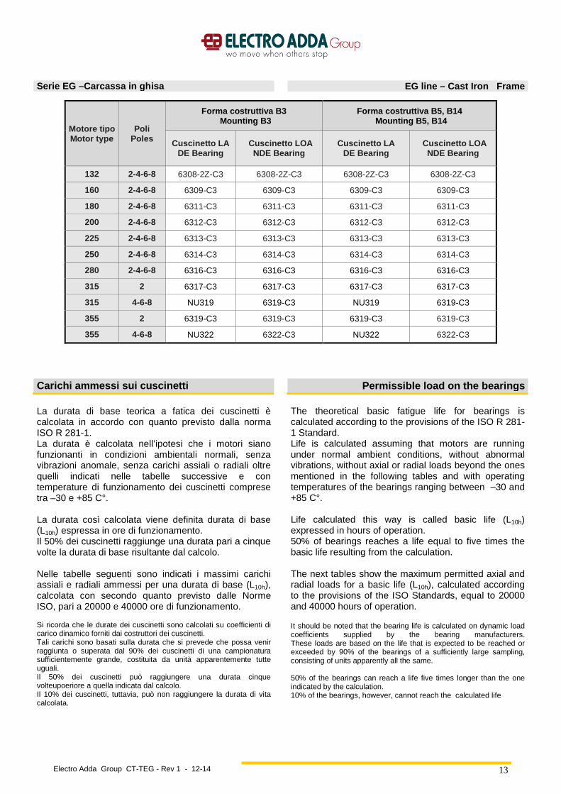
Serie EG –Carcassa in ghisa EG line – Cast Iron Frame
Motore tipo Motor type
Poli Poles
Forma costruttiva B3 Mounting B3
Forma costruttiva B5, B14 Mounting B5, B14
Cuscinetto LA DE Bearing
Cuscinetto LOA NDE Bearing
Cuscinetto LA DE Bearing
Cuscinetto LOA NDE Bearing
132 2-4-6-8 6308-2Z-C3 6308-2Z-C3 6308-2Z-C3 6308-2Z-C3
160 2-4-6-8 6309-C3 6309-C3 6309-C3 6309-C3
180 2-4-6-8 6311-C3 6311-C3 6311-C3 6311-C3
200 2-4-6-8 6312-C3 6312-C3 6312-C3 6312-C3
225 2-4-6-8 6313-C3 6313-C3 6313-C3 6313-C3
250 2-4-6-8 6314-C3 6314-C3 6314-C3 6314-C3
280 2-4-6-8 6316-C3 6316-C3 6316-C3 6316-C3
315 2 6317-C3 6317-C3 6317-C3 6317-C3
315 4-6-8 NU319 6319-C3 NU319 6319-C3
355 2 6319-C3 6319-C3 6319-C3 6319-C3
355 4-6-8 NU322 6322-C3 NU322 6322-C3
Carichi ammessi sui cuscinetti Permissible load on the bearings
La durata di base teorica a fatica dei cuscinetti è calcolata in accordo con quanto previsto dalla norma ISO R 281-1. La durata è calcolata nell’ipotesi che i motori siano funzionanti in condizioni ambientali normali, senza vibrazioni anomale, senza carichi assiali o radiali oltre quelli indicati nelle tabelle successive e con temperature di funzionamento dei cuscinetti comprese tra –30 e +85 C°. La durata così calcolata viene definita durata di base (L10h) espressa in ore di funzionamento. Il 50% dei cuscinetti raggiunge una durata pari a cinque volte la durata di base risultante dal calcolo. Nelle tabelle seguenti sono indicati i massimi carichi assiali e radiali ammessi per una durata di base (L10h), calcolata con secondo quanto previsto dalle Norme ISO, pari a 20000 e 40000 ore di funzionamento. Si ricorda che le durate dei cuscinetti sono calcolati su coefficienti di carico dinamico forniti dai costruttori dei cuscinetti. Tali carichi sono basati sulla durata che si prevede che possa venir raggiunta o superata dal 90% dei cuscinetti di una campionatura sufficientemente grande, costituita da unità apparentemente tutte uguali. Il 50% dei cuscinetti può raggiungere una durata cinque volteupoeriore a quella indicata dal calcolo. Il 10% dei cuscinetti, tuttavia, può non raggiungere la durata di vita calcolata.
The theoretical basic fatigue life for bearings is calculated according to the provisions of the ISO R 281-1 Standard. Life is calculated assuming that motors are running under normal ambient conditions, without abnormal vibrations, without axial or radial loads beyond the ones mentioned in the following tables and with operating temperatures of the bearings ranging between –30 and +85 C°. Life calculated this way is called basic life (L10h) expressed in hours of operation. 50% of bearings reaches a life equal to five times the basic life resulting from the calculation. The next tables show the maximum permitted axial and radial loads for a basic life (L10h), calculated according to the provisions of the ISO Standards, equal to 20000 and 40000 hours of operation. It should be noted that the bearing life is calculated on dynamic load coefficients supplied by the bearing manufacturers. These loads are based on the life that is expected to be reached or exceeded by 90% of the bearings of a sufficiently large sampling, consisting of units apparently all the same. 50% of the bearings can reach a life five times longer than the one indicated by the calculation. 10% of the bearings, however, cannot reach the calculated life
Electro Adda Group CT-TEG - Rev 1 - 12-14
14
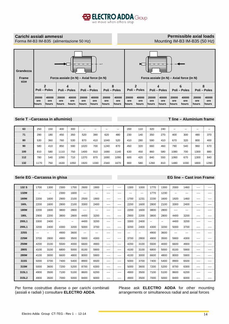
Carichi assiali ammessi Forma IM-B3 IM-B35 (alimentazione 50 Hz)
Permissible axial loads Mounting IM-B3 IM-B35 (50 Hz)
Grandezza
Frame size
Forza assiale (in N) – Axial force (in N )
Forza assiale (in N) – Axial force (in N )
2 Poli – Poles
4 Poli – Poles
6 Poli – Poles
8 Poli – Poles
2 Poli – Poles
4 Poli – Poles
6 Poli – Poles
8 Poli – Poles
20000 ore
hours
40000 ore
hours
20000 ore
hours
40000 ore
hours
20000 ore
hours
40000 ore
hours
20000 ore
hours
40000 ore
hours
20000 ore
hours
40000 ore
hours
20000 ore
hours
40000 ore
hours
20000 ore
hours
40000 ore
hours
20000 ore
hours
40000 ore
hours
Serie T –Carcassa in alluminio) T line – Aluminium frame 63 250 150 400 300 -- -- -- -- 200 110 320 240 -- -- -- --
71 290 180 450 350 520 390 620 480 230 140 350 270 400 300 480 370
80 530 360 760 530 870 410 1040 520 410 280 590 410 670 320 800 400
90 580 410 850 590 1020 700 1240 870 450 320 660 460 790 540 960 670
100 810 580 1110 750 1400 910 1690 1140 630 450 860 580 1080 700 1300 880
112 780 540 1090 710 1370 870 1690 1090 600 420 840 550 1060 670 1300 840
132 1170 750 1630 1050 1920 1330 2340 1670 900 580 1260 810 1480 1030 1800 1290
Serie EG –Carcassa in ghisa EG line – Cast iron Frame
132 S 1700 1300 2300 1700 2600 1900 ---- ---- 1300 1000 1770 1300 2000 1460 ---- ----
132M -- -- 2300 1600 --- -- ---- ---- --- --- 1770 1230 -- --- ---- ----
160M 2200 1600 2900 2100 2500 1900 ---- ---- 1700 1231 2230 1600 1920 1460 ---- ----
160L 2200 1600 2800 2100 3300 2400 ---- ---- 2200 1600 2800 2100 3300 2400 ---- ----
180M 2200 1600 3800 2800 ---- --- ---- ---- 2200 1600 3800 2800 ---- --- ---- ----
180L 2900 2200 3800 2800 4400 3200 ---- ---- 2900 2200 3800 2800 4400 3200 ---- ----
200L1 3300 2400 -- -- 4400 3200 ---- ---- 3300 2400 -- -- 4400 3200 ---- ----
200L1 3200 2400 4300 3200 5000 3700 ---- ---- 3200 2400 4300 3200 5000 3700 ---- ----
225S --- -- 4900 3600 --- --- ---- ---- --- -- 4900 3600 --- --- ---- ----
225M 3700 2800 4900 3500 5900 4300 ---- ---- 3700 2800 4900 3500 5900 4300 ---- ----
250M 4200 3100 5500 4000 6600 4900 ---- ---- 4200 3100 5500 4000 6600 4900 ---- ----
280S 4100 3100 6800 5000 8100 5900 ---- ---- 4100 3100 6800 5000 8100 5900 ---- ----
280M 4100 3000 6600 4800 8000 5900 ---- ---- 4100 3000 6600 4800 8000 5900 ---- ----
315S 5000 3700 7400 5400 8900 6500 ---- ---- 5000 3700 7400 5400 8900 6500 ---- ----
315M 5000 3600 7200 5200 8700 6300 ---- ---- 5000 3600 7200 5200 8700 6300 ---- ----
315L1 4900 3500 7100 5100 8600 6200 ---- ---- 4900 3500 7100 5100 8600 6200 ---- ----
315L2 4900 3500 7000 5000 8400 6000 ---- ---- 4900 3500 7000 5000 8400 6000 ---- ----
Per forme costruttive diverse o per carichi combinati (assiali e radiali ) consultare ELECTRO ADDA .
Please ask ELECTRO ADDA for other mounting arrangements or simultaneous radial and axial forces

Electro Adda Group CT-TEG - Rev 1 - 12-14
15
Carichi radiali ammessi Forma IM-B3 IM-B35 (alimentazione 50 Hz)
Permissible radial loads Mounting IM-B3 IM-B35 (50 Hz)
I valori dei carichi radiali sono dati sia per carichi applicati all'estremità dell'albero (Xmax) che in corrispondenza della battuta sul mozzo dell'albero (X0). I carichi radiali applicabili variano linearmente con il variare del punto di applicazione, pertanto per carichi posti ad una distanza X dalla battuta dell'albero (X0), il carico massimo applicabile è dato dalla seguente espressione:
Values of the radial loads are given both for loads applied to the shaft extension (Xmax) and in correspondence of the face on the shaft hub (X0). Radial loads that can be applied linearly, change with the change of the application point, therefore for loads placed at a distance X from the shaft face (X0), the maximum load that can be applied is given by the following expression:
Dove: Fra = carico radiale ammesso nel punto X Cxo = carico radiale ammesso nel punto X0 Cxmax = carico radiale ammesso nel punto Xmax Xmax = sporgenza d'albero X = distanza dal punto di applicazione del carico radiale alla battuta dell'albero
Where: Fra = permitted radial load at point X Cxo = permitted radial load at point X0 Cxmax = permitted radial load at point Xmax Xmax = shaft extension X = distance from the application point of the radial load to the shaft face
Per verificare che il tiro di cinghia non superi i valori massimi ammessi, si può utilizzare la seguente formula:
To verify that the belt pull does not exceed the maximum value allowed the following formula can be used:
19100 x P x K F = ------------------------------- n x D
In cui F = Forza radiale in N P = Potenza trasmessa in kW n = Velocità in giri/min D = Diametro della puleggia in metri K = 2 per pulegge con tenditore K = 2.25 per pulegge con profilo a “V” K = 2.5÷3 per cinghie piane senza tenditore, o per
servizi pesanti con tutti i tipi di puleggia
In which F = Newton radial force P = Power transmitted in kW n = Number of revs. per minute D = Pulley diameter in metres K = 2 for flat pulley with tension roller K = 2.25 for sheaves with “V” belt K = 2.5÷3 for flat belts without tension roller, or for
heavy duty with any type of pulley
maxmax
max xxxo
X CXX
CCFra +×−=

Electro Adda Group CT-TEG - Rev 1 - 12-14
16
Carichi radiali ammessi Forma IM B3 (50 Hz)
Permissibile radial loads Mounting IM B3 (50 Hz)
Grandez
za
Frame size
2 Poli – Poles
4 Poli – Poles
6 Poli – Poles
8 Poli – Poles
20000 ore hours
40000 ore hours
20000 ore hours
40000 ore hours
20000 ore hours
40000 ore hours
20000 ore hours
40000 ore hours
X0 Xmax X0 Xmax X0 Xmax X0 Xmax X0 Xmax X0 Xmax X0 Xmax X0 Xmax
Serie T –Carcassa in alluminio T line – Aluminium frame
63 360 330 280 230 510 440 390 310 640 520 500 390
71 470 380 360 310 600 510 460 400 850 690 660 520
80 600 490 460 370 780 630 600 500 1000 810 770 630
90 650 540 500 410 850 670 650 510 1360 1090 1050 850
100 960 770 750 590 1200 950 930 740 1350 1350 1080 1040
112 950 850 740 580 1160 920 890 710 2100 1670 1560 1260
132 1500 1200 1140 920 1840 1480 1400 1120 640 520 500 390
Serie EG –Carcassa in ghisa EG line – Cast iron Frame
132 1800 1400 1400 1100 2100 1690 1600 1300 2300 1900 1800 1430 2800 2250 2150 1700
160 3000 2350 2300 1800 3700 2800 2850 2200 4200 3300 3200 2500 4800 3700 3700 2900
180L-LT 4000 3400 3100 2700 5000 4000 3900 3200 5600 4200 4200 3200 6000 4500 4700 3500
200 4600 3840 3600 2900 6400 5100 4400 3600 6600 5500 5100 4200 7300 6000 5600 4600
225 5200 4300 4000 3400 6400 5100 5000 4000 7400 6000 5600 4500 8200 6600 6300 5000
250 5900 4851 4600 3700 7100 5800 5400 4400 8200 6700 6300 5100 9200 7600 7100 5800
280 5800 4874 4400 3700 8300 7000 6300 5300 9900 8400 7600 6400 10700 9000 8100 6800
315M 6400 5700 4600 4100 Vedere costruzione per carichi radiali elevati – See construction for high radial loads
355 L 7400 6700 5600 5100 Vedere costruzione per carichi radiali elevati – See construction for high radial loads
Electro Adda Group CT-TEG - Rev 1 - 12-14
17
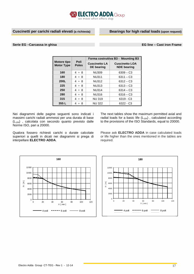
Cuscinetti per carichi radiali elevati (a richiesta) Bearings for high radial loads (upon request)
Serie EG –Carcassa in ghisa EG line – Cast iron Frame
Motore tipo Motor Type
Poli Poles
Forma costruttiva B3 - Mounting B3
Cuscinetto LA DE bearing
Cuscinetto LOA NDE bearing
160 4 ÷ 8 NU309 6309 – C3
180 4 ÷ 8 NU311 6311 – C3
200L 4 ÷ 8 NU312 6312 – C3
225 4 ÷ 8 NU313 6313 – C3
250 4 ÷ 8 NU314 6314 – C3
280 4 ÷ 8 NU316 6316 – C3
315 4 ÷ 8 NU 319 6319 - C3
355 L 4 ÷ 8 NU 322 6322 - C3
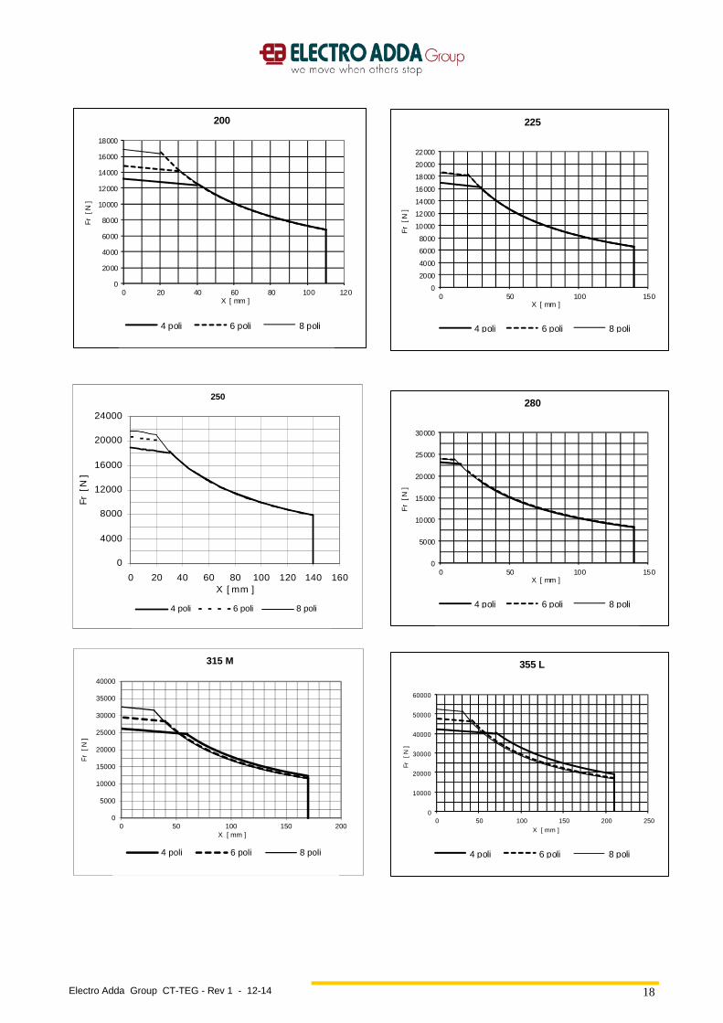
Nei diagrammi delle pagine seguenti sono indicati i massimi carichi radiali ammessi per una durata di base (L10h) , calcolata con secondo quanto previsto dalle Norme ISO, pari a 20000. Qualora fossero richiesti carichi o durate calcolate superiori a quelli in dicati nei diagrammi si prega di interpellare ELECTRO ADDA .
The next tables show the maximum permitted axial and radial loads for a basic life (L10h) , calculated according to the provisions of the ISO Standards, equal to 20000. Please ask ELECTRO ADDA in case calculated loads or life higher than the ones mentioned in the tables are required.
0
2000
4000
6000
8000
10000
12000
0 20 40 60 80 100 120
Fr
[ N
]
X [ mm ]
160
4 poli 6 poli 8 poli
0
2000
4000
6000
8000
10000
12000
0 20 40 60 80 100 120
Fr
[ N ]
X [ mm ]
180
4 poli 6 poli 8 poli
Serie7
Electro Adda Group CT-TEG - Rev 1 - 12-14
18
0
2000
4000
6000
8000
10000
12000
14000
16000
18000
0 20 40 60 80 100 120
Fr
[ N
]
X [ mm ]
200
4 poli 6 poli 8 poli
250
0
4000
8000
12000
16000
20000
24000
0 20 40 60 80 100 120 140 160X [ mm ]
Fr [
N ]
4 poli 6 poli 8 poli
Serie7
0
5000
10000
15000
20000
25000
30000
35000
40000
0 50 100 150 200
Fr
[ N
]
X [ mm ]
315 M
4 poli 6 poli 8 poli
0
2000
4000
6000
8000
10000
12000
14000
16000
18000
20000
22000
0 50 100 150
Fr
[ N
]
X [ mm ]
225
4 poli 6 poli 8 poli
0
5000
10000
15000
20000
25000
30000
0 50 100 150
Fr
[ N
]
X [ mm ]
280
4 poli 6 poli 8 poli
0
10000
20000
30000
40000
50000
60000
0 50 100 150 200 250
Fr
[ N ]
X [ mm ]
355 L
4 poli 6 poli 8 poli
Electro Adda Group CT-TEG - Rev 1 - 12-14
19
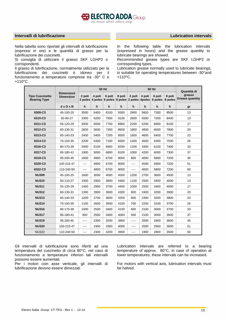
Intervalli di lubrificazione Lubrication intervals
Nella tabella sono riportati gli intervalli di lubrificazione (espressi in ore) e le quantità di grasso per la lubrificazione dei cuscinetti. Si consiglia di utilizzare il grasso SKF LGHP2 o corrispondenti. Il grasso di lubrificazione, normalmente utilizzato per la lubrificazione dei cuscinetti è idoneo per il funzionamento a temperature comprese tra -30° C e +110°C.
In the following table the lubrication intervals (expressed in hours) and the grease quantity to lubricate bearings are showed. Recommended grease types are SKF LGHP2 or corresponding types. Lubrication grease normally used to lubricate bearings, is suitable for operating temperatures between -30°and +110°C.
Tipo Cuscinetto Bearing Type
Dimensioni Dimension
50 Hz 60 Hz Quantità di
grasso Grease quantity
2 poli 2 poles
4 poli 4 poles
6 poli 6 poles
8 poli 8 poles
2 poli 2 poles
4 poli 4poles
6 poli 6 poles
8 poli 8 poles
d x D x B h h h h h h h h gr
6309-C3 45-100-25 3500 6400 8100 9300 2800 5600 7300 8500 13
6310-C3 50-90-27 3300 6200 7900 9100 2600 5500 7200 8400 13
6311-C3 55-120-29 3000 6000 7700 8900 2200 5200 6900 8100 17
6312-C3 60-130-31 2600 5600 7300 8600 1800 4800 6500 7800 20
6313-C3 65-140-33 2400 5400 7200 8500 1600 4600 6400 7700 23
6314-C3 70-150-35 2200 5300 7100 8300 1400 4500 6300 7500 26
6316-C3 80-170-39 2000 5100 6900 8200 1200 4300 6100 7400 33
6317-C3 85-180-41 1900 5000 6800 8100 1000 4200 6000 7300 37
6319-C3 95-200-45 1600 4800 6700 8000 800 4000 5800 7200 45
6320-C3 100-215-47 ---- 4800 6700 8000 ---- 4000 5900 7200 51
6322-C3 110-240-50 ---- 4800 6700 8000 ---- 4000 5800 7200 60
NU309 45-100-25 1600 3000 4000 4500 1200 2700 3600 4500 13
NU310 50-110-27 1500 2900 3800 4400 1100 2500 3400 4000 13
NU311 55-120-29 1400 2900 3700 4400 1000 2500 3400 4000 17
NU312 60-130-31 1300 2800 3600 4300 900 2400 3200 3900 20
NU313 65-140-33 1200 2700 3600 4200 800 2300 3200 3800 23
NU314 70-150-35 1100 2600 3500 4100 700 2200 3100 3700 26
NU316 80-170-39 1000 2500 3400 4100 600 2100 3000 3700 33
NU317 85-180-41 900 2500 3400 4000 500 2100 3000 3600 37
NU319 95.200.45 ----- 2300 3200 3900 ----- 2000 2900 3600 45
NU320 100-215-47 ---- 2400 3300 4000 ---- 2000 2900 3600 51
NU322 110-240-50 ---- 2300 3200 3900 ---- 1900 2800 3500 60
Gli intervalli di lubrificazione sono riferiti ad una temperatura del cuscinetto di circa 80°C, nel caso di funzionamento a temperature inferiori tali intervalli possono essere aumentati. Per i motori coin asse verticale, gli intervalli di lubrificazione devono essere dimezzati
Lubrication intervals are referred to a bearing temperature of approx. 80°C, in case of operation at lower temperatures, these intervals can be increased. For motors with vertical axis, lubrication intervals must be halved.
Electro Adda Group CT-TEG - Rev 1 - 12-14
20
Targhe Rating Plates
Tutti i motori in esecuzione standard sono forniti con targa in alluminio o a richiesta in acciaio inossidabile. Tutte le targhe, realizzate mediante incisione laser, riportano i dati caratteristici della macchina elettrica in accordo con le norme di riferimento, i tipi di cuscinetti e i dati di ingrassaggio. A richiesta del cliente possono essere aggiunte targhe speciali riportanti caratteristiche particolari. Per esempio: Item di impianto ecc..
All motors in standard execution are supplied with aluminium rating plate or, upon request, with stainless steel rating plate. All rating plates, made by laser engraving, contain the distinctive data of the electric machine according to the reference standards, the bearing types and the regreasing data. Upon customer's request, special rating plates mentioning particular features can be added. For example: system item etc
Scatola morsetti e morsettiera Terminal box and block
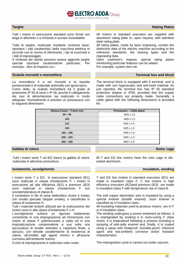
La morsettiera è a sei morsetti e la basetta portamorsetti è di materiale antimuffa non igroscopico. Come detto, la scatola morsettiera ha il grado di protezione IP 55 di serie o IP 56, purché il collegamento dei cavi di alimentazione sia realizzato in modo adeguato. Normalmente è previsto un pressacavo con le seguenti dimensioni:
The terminal block is equipped with 6 terminal, and is made with non hygroscopic and anti-mold material. As just reported, the terminal box has IP 55 standard protection degree or IP56, provided that the supply cable connections are properly made. Generally, a cable gland with the following dimensions is provided for:
Altezza d’asse – Frame size Pressacavo – Cable gland
80 ÷ 90 M20 x 1.5
100 M20 x 1.5
112 M25 x 1.5
132 M25 x 1.5
160 ÷ 180 M40 x 1.5
200 ÷ 225 M50 x 1.5
250 ÷ 355 M63 x 1.5
Gabbia di rotore Rotor cage
Tutti i motori serie T ed EG hanno la gabbia di rotore realizzata in alluminio pressofuso.
All T and EG line motors have the rotor cage in die-casted aluminium.
Isolamento, avvolgimento Insulation, winding
I motori serie T e EG in esecuzione standard (IE1) sono realizzati in classe d’isolamento F; i motori in esecuzione ad alta efficienza (IE2) e premium (IE3) sono realizzati in classe d’isolamento F con sovratemperatura di classe B. Il conduttore in filo di rame elettrolitico ricotto è isolato con smalto speciale (doppio smalto), è classificato in classe di isolamento H. Tutti i materiali isolanti utilizzati per la realizzazione dei motori sono in alla classe d’isolamento F o H. L’avvolgimento subisce un rigoroso trattamento consistente in una impregnazione ad immersione con resine di classe F polimerizzanti a caldo ed in una tropicalizzazione comprendente a sua volta una spruzzatura di smalto antisalso e copertura finale, a spruzzo, con elevate caratteristiche di resistenza al calore, all’umidità agli agenti chimici e all’azione corrosiva dell’ambiente marino. Il ciclo di impregnazione è realizzato sotto vuoto.
T and EG line motors in standard execution (IE1) are made in insulation class F; C line motors in high efficiency execution (IE2)and premium (IE3) are made in insulation class F with temperature rise in class B. The soft copper electrolytic wire is insulated by using a special enamel (double enamel). Such enamel is classified as H insulation class. All insulating materials used to produce motors are in F or H insulation class. The winding undergoes a severe treatment as follows: it is impregnated by soaking it in oven-curing F class resins, it is tropicalized following a process including a spraying of anti-salty enamel and, finally, it is coated using a spray with heatproof, humidity-proof, chemical agent and sea-ambient corrosive action resistant characteristics. The impregnation cycle is carried out under vacuum.
Electro Adda Group CT-TEG - Rev 1 - 12-14
21
Potenza e dati tecnici Ratings and technical data
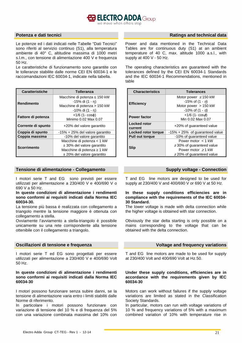
Le potenze ed i dati indicati nelle Tabelle “Dati Tecnici” sono riferiti al servizio continuo (S1), alla temperatura ambiente di 40° C, altitudine massima di 1000 metri s.l.m., con tensione di alimentazione 400 V e frequenza 50 Hz. Le caratteristiche di funzionamento sono garantite con le tolleranze stabilite dalle norme CEI EN 60034-1 e le raccomandazioni IEC 60034-1, indicate nella tabella.
Power and data mentioned in the Technical Data Tables are for continuous duty (S1) at an ambient temperature of 40 C, max. altitude 1000 a.s.l., with supply at 400 V - 50 Hz. The operating characteristics are guaranteed with the tolerances defined by the CEI EN 60034-1 Standards and the IEC 60034-1 Recommendations, mentioned in table
Caratteristiche Tolleranza Characteristics Tolerances
Rendimento
Macchine di potenza ≤ 150 kW -15% di (1 - η)
Macchine di potenza > 150 kW -10% di (1 - η)
Efficiency
Motor power ≤ 150 kW -15% of (1 - η)
Motor power > 150 kW -10% of (1 - η)
Fattore di potenza +1/6 (1- cosϕ) Minimo 0.02 Max 0.07
Power factor +1/6 (1- cosϕ) Min 0.02 Max 0.07
Corrente di spunto +20% del valore garantito Locked rotor current +20% of guaranteed value
Coppia di spunto -15% + 25% del valore garantito Locked rotor torque -15% + 25% of guaranteed value Coppia massima -10% del valore garantito Pull out torque -10% of guaranteed value
Scorrimento
Macchine di potenza < 1 kW ± 30% del valore garantito
Macchine di potenza ≥ 1 kW ± 20% del valore garantito
Slip
Power motor < 1 kW ± 30% of guaranteed value
Power motor ≥ 1 kW ± 20% of guaranteed value
Tensione di alimentazione - Collegamento Supply voltage - Connection
I motori serie T and EG sono previsti per essere utilizzati per alimentazione a 230/400 V e 400/690 V o 690 V a 50 Hz. In queste condizioni di alimentazione i rendimenti sono conformi ai requisiti indicati dalla Norma IEC 60034-30. La tensione più bassa è realizzata con collegamento a triangolo mentre la tensione maggiore è ottenuta con collegamento a stella. Ovviamente l’avviamento a stella-triangolo è possibile unicamente su una rete corrispondente alla tensione ottenibile con il collegamento a triangolo.
T and EG line motors are designed to be used for supply at 230/400 V and 400/690 V or 690 V at 50 Hz. In these supply conditions efficiencies are in compliance with the requirements of the IEC 60034-30 Standard. The lower voltage is made with delta connection while the higher voltage is obtained with star connection. Obviously the star delta starting is only possible on a mains corresponding to the voltage that can be obtained with the delta connection.
Oscillazioni di tensione e frequenza Voltage and frequency variations
I motori serie T ed EG sono progettati per essere utilizzati per alimentazione a 230/400 V e 400/690 Volt 50 Hz. In queste condizioni di alimentazione i rendimenti sono conformi ai requisiti indicati dalla Norma IEC 60034-30 I motori possono funzionare senza subire danni, se la tensione di alimentazione varia entro i limiti stabiliti dalle Norme di riferimento. In particolare i motori possono funzionare con variazione di tensione del 10 % e di frequenza del 5% con una variazione combinata massima del 10% con
T and EG line motors are made to be used for supply at 230/400 Volt and 400/690 Volt at Hz.50. Under these supply conditions, efficiencies are in accordance with the requirements given by IEC 60034-30 Motors can work without failures if the supply voltage variations are limited as stated in the Classification Society Standards. In particular, motors can run with voltage variations of 10 % and frequency variations of 5% with a maximum combined variation of 10% with temperature rise in
Electro Adda Group CT-TEG - Rev 1 - 12-14
22
sovratemperatura conformi a quanto previsto dalle norme di riferimento Questo significa che lo stesso motore può funzionare sulle seguenti reti ancora esistenti: - 220/380 Volt +/- 5 % - 230/400 Volt +/- 10% - 240/415 Volt +/- 5% - 380/660 Volt +/- 5% - 400/600 Volt +/- 10% - 415/720 Volt +/- 5% rispondendo ai requisiti richiesti dalIe normative di numerosi paesi.
compliance with the provisions of the reference Standards. This means that the same motor can run on the following still existing supply mains: - 220/380 Volt +/- 5% - 230/400 Volt +/- 10% - 240/415 Volt +/- 5% - 380/660 Volt +/- 5% . - 400/600 Volt +/- 10% - 415/720 Volt +/- 5% corresponding to the requirements requested by the rules of several Countries.
Funzionamento a 60 Hz Operation at 60 Hz frequency
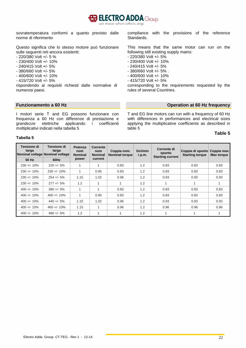
I motori serie T and EG possono funzionare con frequenza a 60 Hz con differenze di prestazione e grandezze elettriche applicando i coefficienti moltiplicativi indicati nella tabella 5 Tabella 5
T and EG line motors can run with a frequency of 60 Hz with differences in performances and electrical sizes applying the multiplicative coefficients as described in table 5
Table 5
Tensione di targa
Nominal voltage
Tensione di targa
Nominal voltage
Potenza nom
Nominal power
Corrente nom
Nominal current
Coppia nom. Nominal torque
Giri/min r.p.m.
Corrente di spunto
Starting current
Coppia di spunto Starting torque
Coppia max Max torque
50 Hz 60Hz
230 +/- 10% 220 +/- 5% 1 1 0.83 1.2 0.83 0.83 0.83
230 +/- 10% 230 +/- 10% 1 0.95 0.83 1.2 0.83 0.83 0.83
230 +/- 10% 254 +/- 5% 1.15 1.02 0.96 1.2 0.93 0.93 0.93
230 +/- 10% 277 +/- 5% 1.2 1 1 1.2 1 1 1
400 +/- 10% 380 +/- 5% 1 1 0.83 1.2 0.83 0.83 0.83
400 +/- 10% 400 +/- 10% 1 0.95 0.83 1.2 0.83 0.83 0.83
400 +/- 10% 440 +/- 5% 1.15 1.02 0.96 1.2 0.93 0.93 0.93
400 +/- 10% 460 +/- 10% 1.15 1 0.96 1.2 0.96 0.96 0.96
400 +/- 10% 480 +/- 5% 1.2 1 1 1.2 1 1 1
Electro Adda Group CT-TEG - Rev 1 - 12-14
23
Squilibrio di tensione Unbalanced voltage
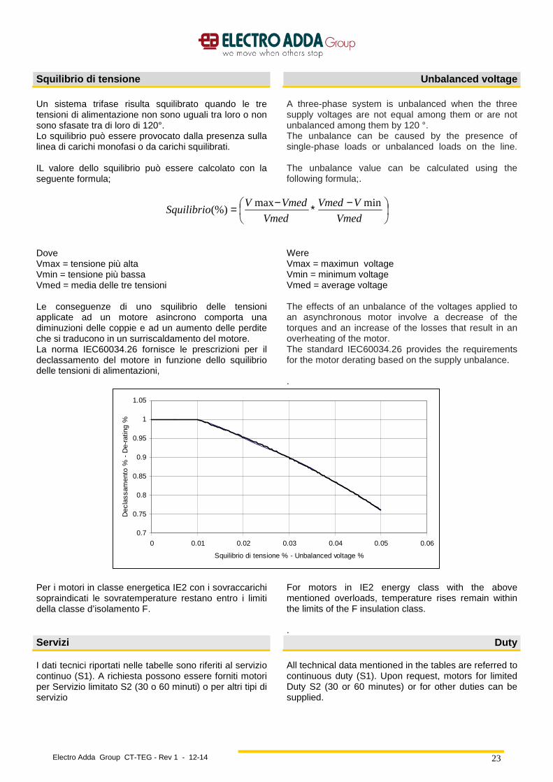
Un sistema trifase risulta squilibrato quando le tre tensioni di alimentazione non sono uguali tra loro o non sono sfasate tra di loro di 120°. Lo squilibrio può essere provocato dalla presenza sulla linea di carichi monofasi o da carichi squilibrati. IL valore dello squilibrio può essere calcolato con la seguente formula;
A three-phase system is unbalanced when the three supply voltages are not equal among them or are not unbalanced among them by 120 °. The unbalance can be caused by the presence of single-phase loads or unbalanced loads on the line. The unbalance value can be calculated using the following formula;.
−∗−=Vmed
VVmed
Vmed
VmedVSquilibrio
minmax(%)
Dove Vmax = tensione più alta Vmin = tensione più bassa Vmed = media delle tre tensioni Le conseguenze di uno squilibrio delle tensioni applicate ad un motore asincrono comporta una diminuzioni delle coppie e ad un aumento delle perdite che si traducono in un surriscaldamento del motore. La norma IEC60034.26 fornisce le prescrizioni per il declassamento del motore in funzione dello squilibrio delle tensioni di alimentazioni,
Were Vmax = maximun voltage Vmin = minimum voltage Vmed = average voltage The effects of an unbalance of the voltages applied to an asynchronous motor involve a decrease of the torques and an increase of the losses that result in an overheating of the motor. The standard IEC60034.26 provides the requirements for the motor derating based on the supply unbalance. .
0.7
0.75
0.8
0.85
0.9
0.95
1
1.05
0 0.01 0.02 0.03 0.04 0.05 0.06
Squilibrio di tensione % - Unbalanced voltage %
Dec
lass
amen
to %
- D
e-ra
ting
%
Per i motori in classe energetica IE2 con i sovraccarichi sopraindicati le sovratemperature restano entro i limiti della classe d’isolamento F.
For motors in IE2 energy class with the above mentioned overloads, temperature rises remain within the limits of the F insulation class. .
Servizi Duty
I dati tecnici riportati nelle tabelle sono riferiti al servizio continuo (S1). A richiesta possono essere forniti motori per Servizio limitato S2 (30 o 60 minuti) o per altri tipi di servizio
All technical data mentioned in the tables are referred to continuous duty (S1). Upon request, motors for limited Duty S2 (30 or 60 minutes) or for other duties can be supplied.

Electro Adda Group CT-TEG - Rev 1 - 12-14
24
Declassamenti Deratings
Le tabelle dei dati tecnici sono riferiti alla temperatura ambiente max 40°C ed altitudine fino a 1000 metri s.l.m Per condizioni ambientali diverse, le potenze variano e si ottengono applicando i fattori correttivi indicati nella tabella, mantenendo le sovratemperatura previste per la classe d’isolamento.
The tables of technical data are referred to an ambient temperature of 40°C and an altitude up to 1000 m.a.s.l. In different environmental conditions output ratings vary, and are obtainable by applying the factors as mentioned in table, maintaining the temperature rise provided for by the insulation class.
Altitudine m.s.l.m. Altitude m.a.s.l.
Temperatura ambiente (°C) Ambient temperature (°C)
30 40 45 50 55 60
<= 1000 1.06 1 0.97 0.94 0.90 0.87
1500 1.04 0.97 0.94 0.91 0.87 0.84
2000 1 0.95 0.92 0.88 0.84 0.81
3000 0.96 0.89 0.86 0.82 0.78 0.74
4000 0.91 0.84 0.80 0.76 0.72 0.67
Sovraccarichi Overloads
I motori in servizio continuo possono sopportare i seguenti sovraccarichi (in coppia)
Continuous duty motors can withstand the following overloads (torque)
Sovraccarico Overload
%
Durata / Duration Min Intervallo
Interval Min . Serie T
T line Serie EG EG Line
10 7 10 15
20 5 6 15
30 4 4 15
40 3 3 15
50 2 2 15
In tali condizioni di funzionamento in sovraccarico, le sovratemperature possono risultare superiori di 10°C ai limiti previsti per la classe d’isolamento. Per i motori in classe energetica IE2 e IE3 con i sovraccarichi sopraindicati le sovratemperature restano entro i limiti della classe d’isolamento F.
In such operation conditions with overload, temperature rises may be 10°C higher than the limits provided for by the insulation class. For motors in IE2and IE3 energy class with the above mentioned overloads, temperature rises remain within the limits of the F insulation class.
Avviamenti Startings
I motori sono idonei per i seguenti tipi di avviamento: • Diretto • Stella – triangolo • Autotrasformatore • Soft-start (1) • con inverter (2)
1) Al termine dell’avviamento il soft-starter deve essere by-passato. In caso contrario è necessario utilizzare un motore con avvolgimento con isolamento rinforzato 2) Vedere paragrafo alimentazione da inverter.
Motors are suitable for the following types of starting • Direct • Star – delta • By autotransformer • Soft-start (1) • by inverter (2)
1) At the end of the starting, the soft-starter must be by-passed. If not, it is necessary to use a motor with winding with reinforced insulation. 2) Please refer to inverter supply paragraph..
Electro Adda Group CT-TEG - Rev 1 - 12-14
25
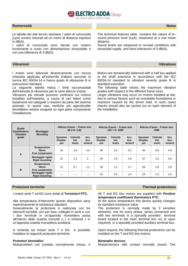
Rumorosità Noise
Le tabelle dei dati tecnici riportano i valori di rumorosità (LpA) sonora misurati ad un metro di distanza espressi in dB(A). I valori di rumorosità sono rilevati con motore funzionante a vuoto con alimentazione sinusoidale e con una tolleranza di 3 dB(A).
The technical features table contains the values of A–sound pressure level (LpA), measured at a one meter distance. Sound levels are measured in no-load conditions with sinusoidal supply and have tolerances of 3 dB(A),
Vibrazioni Vibrations
I motori sono bilanciati dinamicamente con mezza chiavetta applicata all’estremità d’albero secondo la norma IEC 60034-14 e hanno grado di vibrazione B in esecuzione standard. La seguente tabella indica i limiti raccomandati dell’intensità di vibrazione per le varie altezze d’asse. Vibrazioni più elevate possono verificarsi sul motore installato sull’impianto, a causa di vari fattori come basamenti non adeguati o reazioni da parte del sistema azionato. In questi casi, verifiche più approfondite dovrebbero essere eseguite su ogni parte componente l’installazione.
Motors are dynamically balanced with a half key applied to the shaft extension in accordance with the IEC 60034-14 standard to vibration severity grade B in standard execution. The following table shows the maximum vibration grades with respect to the different frame sizes. Larger vibrations may occur on motors installed at site, due to various factors such as unsuitable foundations or reactions caused by the driven load. In such cases checks should also be carried out on each element of the installation.
Grado Equilibratura
Vibration grade
Montaggio Mounting
Altezza d’asse - Frame size 56 ≤ H <132
Altezza d’asse - Frame size 132 < H ≤280
Altezza d’asse - Frame size >280
Spostam Displac . µm
Velocità Vel.
mm/s
Acc. Acc .
m/sec2
Spostam Displac . µm
Velocità Vel.
mm/s
Acc. Acc .
m/sec2
Spostam Displac . µm
Velocità Vel.
mm/s
Acc. Acc .
m/sec2
A
Sospensione libera
Free suspension 25 1.6 2.5 35 2.2 3.5 45 2.8 4.4
Montaggio rigido Rigid mounting 21 1.3 2. 29 1.8 2.8 37 2.3 3.6
B
Sospensione libera
Free suspension 11 0.7 1.1 18 1.1 1.7 29 1.8 2.8
Montaggio rigido Rigid mounting --- --- --- 14 0.9 1.4 24 1.5 2.4
Protezioni termiche Thermal protections
I motori serie T ed EG sono dotati di Termistori PTC. Alla temperatura d’intervento questo dispositivo varia repentinamente la resistenza standard. Generalmente la protezione è realizzata con tre elementi sensibili, uno per fase, collegati in serie e con i due terminali in un’apposita morsettiera posta all’interno della scatola morsetti o ( a richiesta ) in un’apposita scatola morsettiera ausiliaria. A richiesta sui motori serie T e EG è possibile installare le seguenti protezioni termiche: Protettori bimetallici Motoprotettori con contatto normalmente chiuso. Il
All T and EG line motors ara supplied with Positive temperature coefficient thermistors PTC. At the active temperature this device quickly changes its standard resistance value. The protection is normally made by 3 sensitive elements, one for every phase, series connected and with two terminals in a specially provided terminal board located in the main terminal box or( or upon required) in a specially provided auxiliary terminal box. Upon request, the following thermal protections can be installed on the T and EG line motors: Bimetallic devices Motoprotectors with contact normally closed. The

Electro Adda Group CT-TEG - Rev 1 - 12-14
26
contatto si apre quando la temperatura degli avvolgimenti raggiunge limiti pericolosi per il sistema isolante. Termometri a resistenza di platino PT100 Il valore di resistenza varia linearmente con la temperatura degli avvolgimenti. Dispositivo particolarmente adatto per un rilievo continuo della temperatura.
contact opens when the winding temperature reaches limits dangerous to the insulation system of the motor. Platinum resistance thermometers PT100 Variable linear resistance with the winding temperature. Device particularly suitable for a continuous winding temperature monitoring.
Scaldiglie anticondensa Anticondensation heaters
Per i motori funzionanti in ambienti ad elevata umidità e con forti escursioni termiche si consiglia l’applicazione di scaldiglie per eliminare la condensa. Sono di tipo a nastro e vengono montate sulla testata degli avvolgimenti di statore. Viene normalmente prevista la loro alimentazione quando quella del motore viene interrotta, generando un riscaldamento che previene la formazione di condensa. La tensione di alimentazione normale è 115 V o 220/240V. I terminali delle scaldiglie sono portati ad un’apposita morsettiera posta all’interno della scatola morsetti principale. A richiesta possono essere portati ad una morsettiera posta in una scatola morsetti ausiliari. Le potenze normalmente impiegate sono indicate nella tabella seguente.
Motors subject to atmospheric condensation, either through standing idle in damp environments or because of wide ambient temperature variations, may be fitted with anticondensation heaters. They are of tape form and are normally mounted on the stator winding head. Anticondensation heaters are normally switched on automatically when the supply to the motor is interrupted, heating the motor to avoid water condensation. Normal supply voltage is 115 V or 220/240V. Anticondensation heater terminals are led to a specially provided terminal board located in the main terminal box. Upon request they can be led to a terminal board located in an auxiliary terminal box. The power values normally used are shown in the following table.
Serie T A – Carcassa in alluminio TA Line – Aluminium Frame
Altezza d’asse - Frame size Potenza (W) - Power (W)
63 A richiesta – On request
71 ÷ 90 8
100 ÷ 132 22
Serie EG – Carcassa in ghisa EG Line – Cast iron Frame
Altezza d’asse - Frame size Potenza (W) - Power (W)
132÷160 40
180÷200 45
225÷250 50
280÷315 100
355 200
400 300
450 400
500 500
Verniciatura Painting
I motori sono verniciati con colore RAL 7030. A richiesta sono disponibili trattamenti superficiali per ambienti aggressivi o colori diversi.
Motors are painted with color RAL 7030. On request, surface treatment for aggressive environments and other colors are available.
Electro Adda Group CT-TEG - Rev 1 - 12-14
27
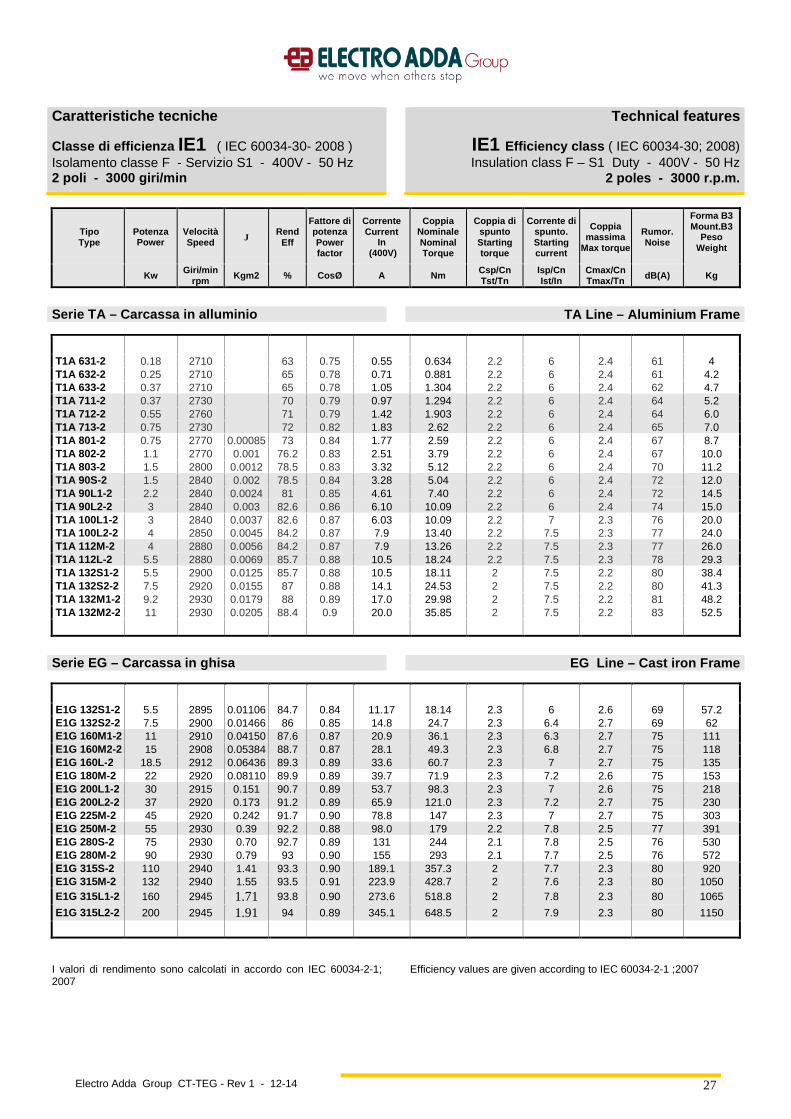
Carat teristiche tecniche
Classe di efficienza IE1 ( IEC 60034-30- 2008 ) Isolamento classe F - Servizio S1 - 400V - 50 Hz 2 poli - 3000 giri/min
Technical features
IE1 Efficiency class ( IEC 60034-30; 2008) Insulation class F – S1 Duty - 400V - 50 Hz
2 poles - 3000 r.p.m.
Tipo Type
Potenza Powe r
Velocità Speed J
Rend Eff
Fattore di potenza Power factor
Corrente Current
In (400V)
Coppia Nominale Nominal Torque
Coppia di spunto Starting torque
Corrente di spunto. Starting current
Coppia massima
Max torque
Rumor . Noise
Forma B3 Mount.B3
Peso Weight
Kw Giri/min rpm Kgm2 % CosØ A Nm Csp/Cn
Tst/Tn Isp/Cn Ist/In
Cmax/Cn Tmax/Tn dB(A) Kg
Serie T A – Carcassa in alluminio TA Line – Aluminium Frame
T1A 631-2 0.18 2710 63 0.75 0.55 0.634 2.2 6 2.4 61 4 T1A 632-2 0.25 2710 65 0.78 0.71 0.881 2.2 6 2.4 61 4.2 T1A 633-2 0.37 2710 65 0.78 1.05 1.304 2.2 6 2.4 62 4.7 T1A 711-2 0.37 2730 70 0.79 0.97 1.294 2.2 6 2.4 64 5.2 T1A 712-2 0.55 2760 71 0.79 1.42 1.903 2.2 6 2.4 64 6.0 T1A 713-2 0.75 2730 72 0.82 1.83 2.62 2.2 6 2.4 65 7.0 T1A 801-2 0.75 2770 0.00085 73 0.84 1.77 2.59 2.2 6 2.4 67 8.7 T1A 802-2 1.1 2770 0.001 76.2 0.83 2.51 3.79 2.2 6 2.4 67 10.0 T1A 803-2 1.5 2800 0.0012 78.5 0.83 3.32 5.12 2.2 6 2.4 70 11.2 T1A 90S-2 1.5 2840 0.002 78.5 0.84 3.28 5.04 2.2 6 2.4 72 12.0 T1A 90L1-2 2.2 2840 0.0024 81 0.85 4.61 7.40 2.2 6 2.4 72 14.5 T1A 90L2-2 3 2840 0.003 82.6 0.86 6.10 10.09 2.2 6 2.4 74 15.0 T1A 100L1-2 3 2840 0.0037 82.6 0.87 6.03 10.09 2.2 7 2.3 76 20.0 T1A 100L2-2 4 2850 0.0045 84.2 0.87 7.9 13.40 2.2 7.5 2.3 77 24.0 T1A 112M-2 4 2880 0.0056 84.2 0.87 7.9 13.26 2.2 7.5 2.3 77 26.0 T1A 112L-2 5.5 2880 0.0069 85.7 0.88 10.5 18.24 2.2 7.5 2.3 78 29.3 T1A 132S1-2 5.5 2900 0.0125 85.7 0.88 10.5 18.11 2 7.5 2.2 80 38.4 T1A 132S2-2 7.5 2920 0.0155 87 0.88 14.1 24.53 2 7.5 2.2 80 41.3 T1A 132M1-2 9.2 2930 0.0179 88 0.89 17.0 29.98 2 7.5 2.2 81 48.2 T1A 132M2-2 11 2930 0.0205 88.4 0.9 20.0 35.85 2 7.5 2.2 83 52.5
Serie EG – Carcas sa in ghisa EG Line – Cast iron Frame
E1G 132S1-2 5.5 2895 0.01106 84.7 0.84 11.17 18.14 2.3 6 2.6 69 57.2 E1G 132S2-2 7.5 2900 0.01466 86 0.85 14.8 24.7 2.3 6.4 2.7 69 62 E1G 160M1-2 11 2910 0.04150 87.6 0.87 20.9 36.1 2.3 6.3 2.7 75 111 E1G 160M2-2 15 2908 0.05384 88.7 0.87 28.1 49.3 2.3 6.8 2.7 75 118 E1G 160L-2 18.5 2912 0.06436 89.3 0.89 33.6 60.7 2.3 7 2.7 75 135 E1G 180M-2 22 2920 0.08110 89.9 0.89 39.7 71.9 2.3 7.2 2.6 75 153 E1G 200L1-2 30 2915 0.151 90.7 0.89 53.7 98.3 2.3 7 2.6 75 218 E1G 200L2-2 37 2920 0.173 91.2 0.89 65.9 121.0 2.3 7.2 2.7 75 230 E1G 225M-2 45 2920 0.242 91.7 0.90 78.8 147 2.3 7 2.7 75 303 E1G 250M-2 55 2930 0.39 92.2 0.88 98.0 179 2.2 7.8 2.5 77 391 E1G 280S-2 75 2930 0.70 92.7 0.89 131 244 2.1 7.8 2.5 76 530 E1G 280M-2 90 2930 0.79 93 0.90 155 293 2.1 7.7 2.5 76 572 E1G 315S-2 110 2940 1.41 93.3 0.90 189.1 357.3 2 7.7 2.3 80 920 E1G 315M-2 132 2940 1.55 93.5 0.91 223.9 428.7 2 7.6 2.3 80 1050 E1G 315L1-2 160 2945 1.71 93.8 0.90 273.6 518.8 2 7.8 2.3 80 1065
E1G 315L2-2 200 2945 1.91 94 0.89 345.1 648.5 2 7.9 2.3 80 1150
I valori di rendimento sono calcolati in accordo con IEC 60034-2-1; 2007 Efficiency values are given according to IEC 60034-2-1 ;2007
Electro Adda Group CT-TEG - Rev 1 - 12-14
28
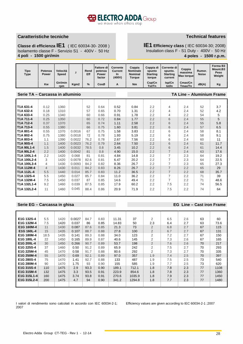
Caratteristiche tecniche
Classe di efficienza IE1 ( IEC 60034-30- 2008 ) Isolamento classe F - Servizio S1 - 400V - 50 Hz 4 poli - 1500 giri/min
Technical features
IE1 Efficiency class ( IEC 60034-30; 2008) Insulation class F - S1 Duty - 400V - 50 Hz
4 poles - 1500 r.p.m .
Tipo Type
Potenza Powe r
Velocità Speed J Rend
Eff
Fattore di potenza Power factor
Corrente Current
In (400V)
Coppia Nominale Nominal Torque
Coppia di spunto Starting torque
Corrente di spunto. Starting current
Coppia massima
Max torque
Rumor . Noise
Forma B3 Mount.B3
Peso Weight
Kw Giri/min rpm
Kgm2 % CosØ A Nm Csp/Cn Tst/Tn
Isp/Cn Ist/In
Cmax/Cn Tmax/Tn
dB(A) Kg
Serie T A – Carcassa in alluminio TA Line – Aluminium Frame
T1A 631-4 0.12 1360 52 0.64 0.52 0.84 2.2 4 2.4 52 3.7 T1A 632-4 0.18 1310 57 0.65 0.70 1.31 2.2 4 2.4 52 4.2 T1A 633-4 0.25 1340 60 0.66 0.91 1.78 2.2 4 2.2 54 5 T1A 711-4 0.25 1350 60 0.72 0.84 1.77 2.2 6 2.4 55 5 T1A 712-4 0.37 1370 65 0.74 1.11 2.58 2.2 6 2.4 55 5.8 T1A 713-4 0.55 1380 66 0.75 1.60 3.81 2.2 6 2.4 57 6.5 T1A 801-4 0.55 1370 0.0016 67 0.75 1.58 3.83 2.2 6 2.4 58 8.1 T1A 802-4 0.75 1380 0.0018 72 0.78 1.93 5.19 2.2 6 2.4 58 9.1 T1A 803-4 1.1 1390 0.0022 76.2 0.78 2.67 7.56 2.2 6 2.4 60 11 T1A 90S-4 1.1 1400 0.0023 76.2 0.79 2.64 7.50 2.2 6 2.4 61 11.7 T1A 90L1-4 1.5 1400 0.0032 78.5 0.8 3.45 10.2 2.2 6 2.4 61 14.4 T1A 90L2-4 2.2 1400 0.0042 81 0.8 4.90 15.0 2.2 7 2.4 63 17.6 T1A 100L1-4 2.2 1420 0.068 81 0.81 4.84 14.8 2.2 7 2.3 64 19.2 T1A 100L2-4 3 1420 0.0078 82.6 0.81 6.47 20.2 2.2 7 2.3 64 22.5 T1A 100L3-4 4 1430 0.0093 84.2 0.82 8.36 26.7 2.2 7 2.3 65 27.3 T1A 112M-4 4 1430 0.011 84.2 0.83 8.26 26.7 2.2 7 2.2 65 29 T1A 112L-4 5.5 1440 0.014 85.7 0.83 11.2 36.5 2.2 7 2.2 68 35.7 T1A 132S-4 5.5 1450 0.027 85.7 0.84 11.0 36.2 2.2 7 2.2 71 39 T1A 132M-4 7.5 1450 0.037 87 0.85 14.6 49.4 2.2 7 2.2 71 48.6 T1A 132L1-4 9.2 1460 0.039 87.5 0.85 17.9 60.2 2.2 7.5 2.2 74 56.5
T1A 132L2-4 11 1460 0.045 88.4 0.86 20.9 71.9 2.2 7.5 2.2 74 64
Serie EG – Carcassa in ghisa EG Line – Cast iron Frame
E1G 132S-4 5.5 1420 0.0027 84.7 0.83 11.31 37 2 6.5 2.6 63 60 E1G 132M-4 7.5 1420 0.037 86 0.85 14.83 50 2.3 6.4 2.7 63 73.6 E1G 160M-4 11 1430 0.087 87.6 0.85 21.3 73 2 6.8 2.7 67 115 E1G 160L-4 15 1435 0.107 88.7 0.88 27.8 100 2 6.7 2.7 67 131
E1G 180M-4 18.5 1435 0.141 89.3 0.88 34.0 123 2 7.2 2.7 67 150 E1G 180L-4 22 1450 0.165 89.9 0.87 40.6 145 2 7.3 2.6 67 165 E1G 200L-4 30 1450 0.266 90.7 0.89 53.7 198 2 7.6 2.6 70 217 E1G 225S-4 37 1460 0.50 91.2 0.89 65.9 242 2 7.5 2.7 70 293 E1G 225M-4 45 1470 0.58 91.7 0.88 80.6 292 2 7.3 2.7 70 335 E1G 250M-4 55 1470 0.69 92.1 0.89 97.0 357 1.9 7.4 2.5 70 397 E1G 280S-4 75 1470 1.41 92.7 0.88 133 487 1.9 7.5 2.5 73 540 E1G 280M-4 90 1470 1.75 93 0.90 155 585 1.9 7.7 2.5 73 620 E1G 315S-4 110 1475 2.9 93.3 0.90 189.1 712.1 1.8 7.8 2.3 77 1108 E1G 315M-4 132 1475 3.3 93.5 0.91 223.9 854.6 1.8 7.8 2.3 77 1360 E1G 315L1-4 160 1475 3.74 93.8 0.91 270.6 1035.9 1.8 7.9 2.3 77 1450 E1G 315L2-4 200 1475 4.7 94 0.90 341.2 1294.8 1.8 7.7 2.3 77 1480
I valori di rendimento sono calcolati in accordo con IEC 60034-2-1; 2007 Efficiency values are given according to IEC 60034-2-1 ;2007
Electro Adda Group CT-TEG - Rev 1 - 12-14
29
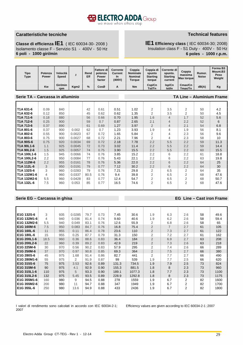
Caratteristiche tecniche
Classe di efficienza IE1 ( IEC 60034-30- 2008 ) Isolamento classe F - Servizio S1 - 400V - 50 Hz 6 poli - 1000 giri/min
Technical features
IE1 Efficiency class ( IEC 60034-30; 2008) Insulation class F - S1 Duty - 400V - 50 Hz
6 poles - 1000 r.p.m .
Tipo Type
Potenza Powe r
Velocità Speed J
Rend Eff
Fattore di potenza Power factor
Corrente Current
In (400V)
Coppia Nominale Nominal Torque
Coppia di spunto Starting torque
Corrente di spunto. Starting current
Coppia massima
Max torque
Rumor . Noise
Forma B3 Mount.B3
Peso Weight
Kw Giri/min rpm
Kgm2 % CosØ A Nm Csp/Cn Tst/Tn
Isp/Cn Ist/In
Cmax/Cn Tmax/Tn
dB(A) Kg
Serie T A – Carcassa in alluminio TA Line – Aluminium Frame
T1A 631-6 0.09 840 42 0.61 0.51 1.02 2 3.5 2 50 4.2 T1A 632-6 0.12 850 45 0.62 0.62 1.35 2 3.5 2 50 4.5 T1A 711-6 0.18 880 56 0.66 0.70 1.95 1.6 4 1.7 52 5.6 T1A 712-6 0.25 900 59 0.7 0.87 2.65 2.1 4 2.2 52 6 T1A 713-6 0.37 890 61 0.69 1.27 3.97 2 4 2.1 54 6.8 T1A 801-6 0.37 900 0.002 62 0.7 1.23 3.93 1.9 4 1.9 56 8.1 T1A 802-6 0.55 900 0.0023 67 0.72 1.65 5.84 2 4 2.3 56 9.6 T1A 803-6 0.75 900 0.0027 68 0.72 2.21 7.96 2 4 2.3 58 10 T1A 90S-6 0.75 920 0.0034 69 0.72 2.18 7.78 2.2 5.5 2.2 59 11.3 T1A 90L1-6 1.1 925 0.0045 72 0.73 3.02 11.4 2.2 5.5 2.2 59 14.4 T1A 90L2-6 1.5 925 0.0057 74 0.75 3.90 15.5 2.2 5.5 2.2 60 15.5 T1A 100L1-6 1.5 945 0.0066 74 0.76 3.85 15.2 2.2 6 2.2 61 18.8 T1A 100L2-6 2.2 950 0.0084 77 0.76 5.43 22.1 2.2 6 2.2 63 19.8 T1A 112M-6 2.2 955 0.0161 78 0.76 5.36 22.0 2.2 6 2.2 64 25 T1A 112L-6 3 950 0.0191 79 0.77 7.12 30.2 2.2 6 2.2 64 30 T1A 132S-6 3 960 0.0283 79 0.76 7.21 29.8 2 6.5 2 64 35 T1A 132M1-6 4 960 0.0337 80.5 0.76 9.4 39.8 2 6.5 2 68 47.6 T1A 132M2-6 5.5 960 0.0428 83 0.77 12.4 54.7 2 6.5 2 68 50.7 T1A 132L-6 7.5 960 0.053 85 0.77 16.5 74.6 2 6.5 2 68 47.6
Serie EG – Carcassa in ghisa EG Line – Cast iron Frame
E1G 132S-6 3 935 0.0285 79.7 0.73 7.45 30.6 1.9 6.3 2.6 58 49.6 E1G 132M1-6 4 940 0.036 81.4 0.74 9.60 40.6 1.9 6.2 2.6 58 59.4 E1G 132M2-6 5.5 940 0.049 83.1 0.76 12.6 55.9 2 6.8 2.6 58 65 E1G 160M-6 7.5 950 0.083 84.7 0.76 16.8 75.4 2 7 2.7 61 105 E1G 160L-6 11 955 0.11 86.4 0.78 23.6 110 2 7.3 2.7 61 122 E1G 180L-6 15 955 0.25 87.7 0.79 31.3 150 2 7.2 2.7 61 162 E1G 200L1-6 18.5 960 0.36 88.6 0.83 36.4 184 2 6.9 2.7 63 208 E1G 200L2-6 22 960 0.39 89.2 0.83 42.9 219 2 7.3 2.6 63 218 E1G 225M-6 30 970 0.56 90.2 0.83 57.9 295 2 7.4 2.6 66 289 E1G 250M-6 37 970 0.97 90.8 0.85 69.3 364 2 7.5 2.7 66 380 E1G 280S-6 45 975 1.68 91.4 0.86 82.7 441 2 7.7 2.7 66 490 E1G 280M1-6 55 975 2 91.9 0.87 99 539 1.9 7.7 2.5 66 620 E1G 315S-6 75 975 3.53 92.6 0.89 131.3 734.5 1.9 7.9 2.5 73 824 E1G 315M-6 90 975 4.1 92.9 0.90 155.3 881.5 1.8 8 2.3 73 960 E1G 315L1-6 110 975 5 93.3 0.90 189.1 1077.3 1.8 7.7 2.3 73 1100 E1G 315L2-6 132 975 5.45 93.5 0.89 228.9 1292.8 1.8 8 2.3 73 1175 E1G 355M1-6 160 980 9 94.5 0.88 278 1559 1.9 6.7 2 82 1600 E1G 355M2-6 200 980 11 94.7 0.88 347 1949 1.9 6.7 2 82 1700 E1G 355L-6 250 980 13.6 94.9 0.88 433 2436 1.9 6.7 2 82 1800
I valori di rendimento sono calcolati in accordo con IEC 60034-2-1; 2007 Efficiency values are given according to IEC 60034-2-1 ;2007
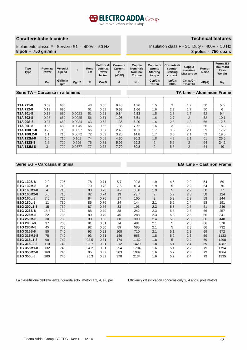
Electro Adda Group CT-TEG - Rev 1 - 12-14
30
Caratteristiche tecniche
Isolamento classe F - Servizio S1 - 400V - 50 Hz 8 poli - 750 giri/min
Technical features
Insulation class F - S1 Duty - 400V - 50 Hz 8 poles - 750 r.p.m .
Tipo Type
Potenza Powe r
Velocità Speed J Rend
Eff
Fattore di potenza Power factor
Corrente Current
In (400V)
Coppia Nominale Nominal Torque
Coppia di spunto Starting torque
Corrente di spunto. Starting current
Coppia massima
Max torque
Rumor . Noise
Forma B3 Mount.B3
Peso Weight
Kw Giri/min rpm
Kgm2 % CosØ A Nm Csp/Cn Tst/Tn
Isp/Cn Ist/In
Cmax/Cn Tmax/Tn
dB(A) Kg
Serie T A – Carcassa in alluminio TA Line – Aluminium Frame
T1A 711-8 0.09 680 48 0.56 0.48 1.26 1.5 3 1.7 50 5.6 T1A 712-8 0.12 690 51 0.59 0.58 1.66 1.6 2.7 1.7 50 6 T1A 801-8 0.18 680 0.0023 51 0.61 0.84 2.53 1.5 2.8 1.7 52 9.4 T1A 802-8 0.25 680 0.0025 56 0.61 1.06 3.51 1.6 2.7 2 52 10.1 T1A 90S-8 0.37 680 0.0034 63 0.63 1.35 5.20 1.6 2.8 1.8 56 12.5 T1A 90L-8 0.55 680 0.0045 66 0.65 1.85 7.72 1.6 3 1.8 56 15.3 T1A 100L1-8 0.75 710 0.0057 66 0.67 2.45 10.1 1.7 3.5 2.1 59 17.2 T1A 100L2-8 1.1 710 0.0072 72 0.69 3.20 14.8 1.7 3.5 2.1 59 19.5 T1A 112M-8 1.5 710 0.161 74 0.68 4.30 20.2 1.8 4.2 2.1 61 25.5 T1A 132S-8 2.2 720 0.296 75 0.71 5.96 29.2 2 5.5 2 64 34.2 T1A 132M-8 3 720 0.0377 77 0.73 7.70 39.8 2 5.5 2 64 40
Serie EG – Carcassa in ghisa EG Line – Cast iron Frame
E1G 132S-8 2.2 705 78 0.71 5.7 29.8 1.9 4.6 2.2 54 59 E1G 132M-8 3 710 79 0.72 7.6 40.4 1.9 5 2.2 54 70 E1G 160M1-8 4 710 80 0.73 9.9 53.8 1.9 5 2.2 58 77 E1G 160M2-8 5.5 715 82 0.74 13 73.7 2 5.2 2.3 58 124 E1G 160L-8 7.5 725 84 0.75 17 100 2 5.3 2.3 58 144 E1G 180L-8 11 730 85 0.76 24 144 2.1 5.2 2.4 58 191 E1G 200L1-8 15 730 87 0.76 33 196 2.3 5.3 2.5 61 246 E1G 225S-8 18.5 730 88 0.79 38 242 2.3 5.3 2.5 66 257 E1G 225M-8 22 735 89 0.79 45 288 2.3 5.3 2.5 66 341 E1G 250M-8 30 735 90 0.80 60 390 2.4 5.3 2.6 66 448 E1G 280S-8 37 735 91 0.81 74 481 2.1 5 2.3 66 578 E1G 280M-8 45 735 92 0.80 89 585 2.1 5 2.3 66 732 E1G 315S-8 55 740 93 0.81 108 710 2.1 5.1 2.3 69 972 E1G 315M1-8 75 740 93 0.81 146 968 1.8 5.2 2.3 69 1133 E1G 315L1-8 90 740 93.5 0.81 174 1162 1.8 5 2.2 69 1298 E1G 315L2-8 110 740 93.7 0.81 212 1420 1.8 5.1 2.4 69 1387 E1G 355M1-8 132 740 94.2 0.81 254 1704 1.6 5.1 2.2 79 1794 E1G 355M2-8 160 740 95 0.82 303 1987 1.6 5.2 2.3 79 1864 E1G 355L-8 200 740 95.3 0.82 378 2134 1.6 5.2 2.4 79 1935
La classifizione dell’efficienza riguarda solo i motori a 2, 4, e 6 poli
Efficiency classification concerns only 2, 4 and 6 pole motors
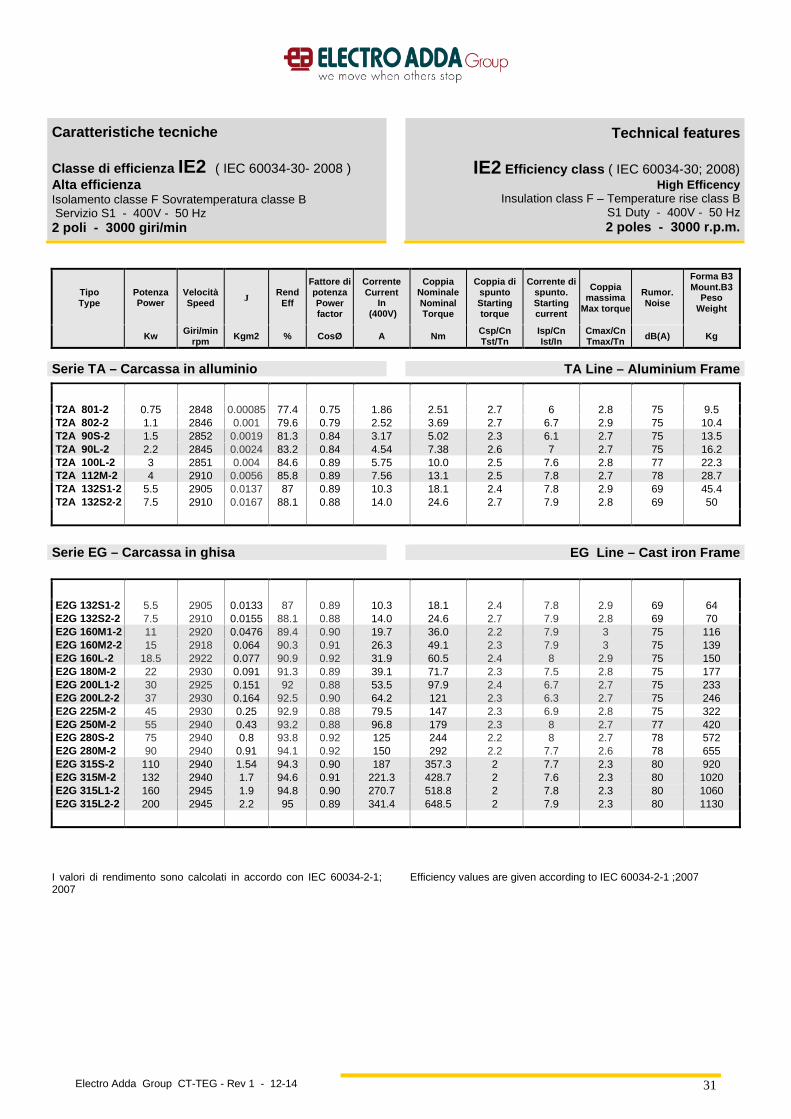
Electro Adda Group CT-TEG - Rev 1 - 12-14
31
Caratteristiche tecniche
Classe di efficienza IE2 ( IEC 60034-30- 2008 ) Alta efficienza Isolamento classe F Sovratemperatura classe B Servizio S1 - 400V - 50 Hz 2 poli - 3000 giri/min
Technical features
IE2 Efficiency class ( IEC 60034-30; 2008) High Efficency
Insulation class F – Temperature rise class B S1 Duty - 400V - 50 Hz 2 poles - 3000 r.p.m.
Tipo Type
Potenza Powe r
Velocità Speed J
Rend Eff
Fattore di potenza Power factor
Corrente Current
In (400V)
Coppia Nominale Nominal Torque
Coppia di spunto Starting torque
Corrente di spunto. Starting current
Coppia massima
Max torque
Rumor . Noise
Forma B3 Mount.B3
Peso Weight
Kw Giri/min rpm Kgm2 % CosØ A Nm Csp/Cn
Tst/Tn Isp/Cn Ist/In
Cmax/Cn Tmax/Tn dB(A) Kg
Serie T A – Carcassa in alluminio TA Line – Aluminium Frame
T2A 801-2 0.75 2848 0.00085 77.4 0.75 1.86 2.51 2.7 6 2.8 75 9.5 T2A 802-2 1.1 2846 0.001 79.6 0.79 2.52 3.69 2.7 6.7 2.9 75 10.4 T2A 90S-2 1.5 2852 0.0019 81.3 0.84 3.17 5.02 2.3 6.1 2.7 75 13.5 T2A 90L-2 2.2 2845 0.0024 83.2 0.84 4.54 7.38 2.6 7 2.7 75 16.2 T2A 100L-2 3 2851 0.004 84.6 0.89 5.75 10.0 2.5 7.6 2.8 77 22.3 T2A 112M-2 4 2910 0.0056 85.8 0.89 7.56 13.1 2.5 7.8 2.7 78 28.7 T2A 132S1-2 5.5 2905 0.0137 87 0.89 10.3 18.1 2.4 7.8 2.9 69 45.4 T2A 132S2-2 7.5 2910 0.0167 88.1 0.88 14.0 24.6 2.7 7.9 2.8 69 50
Serie EG – Carcassa in ghisa EG Line – Cast iron Frame
E2G 132S1-2 5.5 2905 0.0133 87 0.89 10.3 18.1 2.4 7.8 2.9 69 64 E2G 132S2-2 7.5 2910 0.0155 88.1 0.88 14.0 24.6 2.7 7.9 2.8 69 70 E2G 160M1-2 11 2920 0.0476 89.4 0.90 19.7 36.0 2.2 7.9 3 75 116 E2G 160M2-2 15 2918 0.064 90.3 0.91 26.3 49.1 2.3 7.9 3 75 139 E2G 160L-2 18.5 2922 0.077 90.9 0.92 31.9 60.5 2.4 8 2.9 75 150 E2G 180M-2 22 2930 0.091 91.3 0.89 39.1 71.7 2.3 7.5 2.8 75 177 E2G 200L1-2 30 2925 0.151 92 0.88 53.5 97.9 2.4 6.7 2.7 75 233 E2G 200L2-2 37 2930 0.164 92.5 0.90 64.2 121 2.3 6.3 2.7 75 246 E2G 225M-2 45 2930 0.25 92.9 0.88 79.5 147 2.3 6.9 2.8 75 322 E2G 250M-2 55 2940 0.43 93.2 0.88 96.8 179 2.3 8 2.7 77 420 E2G 280S-2 75 2940 0.8 93.8 0.92 125 244 2.2 8 2.7 78 572 E2G 280M-2 90 2940 0.91 94.1 0.92 150 292 2.2 7.7 2.6 78 655 E2G 315S-2 110 2940 1.54 94.3 0.90 187 357.3 2 7.7 2.3 80 920 E2G 315M-2 132 2940 1.7 94.6 0.91 221.3 428.7 2 7.6 2.3 80 1020 E2G 315L1-2 160 2945 1.9 94.8 0.90 270.7 518.8 2 7.8 2.3 80 1060 E2G 315L2-2 200 2945 2.2 95 0.89 341.4 648.5 2 7.9 2.3 80 1130
I valori di rendimento sono calcolati in accordo con IEC 60034-2-1; 2007
Efficiency values are given according to IEC 60034-2-1 ;2007
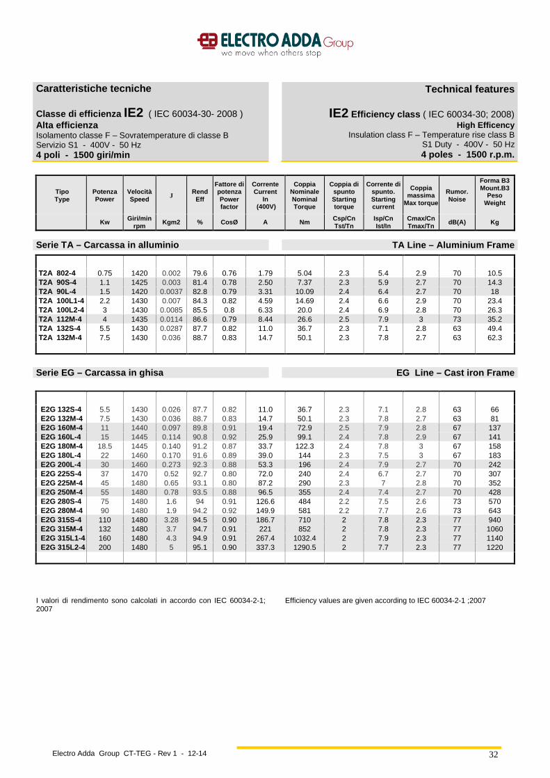
Electro Adda Group CT-TEG - Rev 1 - 12-14
32
Caratteristiche tecniche
Classe di efficienza IE2 ( IEC 60034-30- 2008 ) Alta efficienza Isolamento classe F – Sovratemperature di classe B Servizio S1 - 400V - 50 Hz 4 poli - 1500 giri/min
Technical features
IE2 Efficiency class ( IEC 60034-30; 2008) High Efficency
Insulation class F – Temperature rise class B S1 Duty - 400V - 50 Hz 4 poles - 1500 r.p.m.
Tipo Type
Potenza Powe r
Velocità Speed J
Rend Eff
Fattore di potenza Power factor
Corrente Current
In (400V)
Coppia Nominale Nominal Torque
Coppia di spunto Starting torque
Corrente di spunto. Starting current
Coppia massima
Max torque
Rumor . Noise
Forma B3 Mount.B3
Peso Weight
Kw Giri/min rpm
Kgm2 % CosØ A Nm Csp/Cn Tst/Tn
Isp/Cn Ist/In
Cmax/Cn Tmax/Tn
dB(A) Kg
Serie T A – Carcassa in alluminio TA Line – Aluminium Frame
T2A 802-4 0.75 1420 0.002 79.6 0.76 1.79 5.04 2.3 5.4 2.9 70 10.5 T2A 90S-4 1.1 1425 0.003 81.4 0.78 2.50 7.37 2.3 5.9 2.7 70 14.3 T2A 90L-4 1.5 1420 0.0037 82.8 0.79 3.31 10.09 2.4 6.4 2.7 70 18 T2A 100L1-4 2.2 1430 0.007 84.3 0.82 4.59 14.69 2.4 6.6 2.9 70 23.4 T2A 100L2-4 3 1430 0.0085 85.5 0.8 6.33 20.0 2.4 6.9 2.8 70 26.3 T2A 112M-4 4 1435 0.0114 86.6 0.79 8.44 26.6 2.5 7.9 3 73 35.2 T2A 132S-4 5.5 1430 0.0287 87.7 0.82 11.0 36.7 2.3 7.1 2.8 63 49.4 T2A 132M-4 7.5 1430 0.036 88.7 0.83 14.7 50.1 2.3 7.8 2.7 63 62.3
Serie EG – Carcassa in ghisa EG Line – Cast iron Frame
E2G 132S-4 5.5 1430 0.026 87.7 0.82 11.0 36.7 2.3 7.1 2.8 63 66 E2G 132M-4 7.5 1430 0.036 88.7 0.83 14.7 50.1 2.3 7.8 2.7 63 81 E2G 160M-4 11 1440 0.097 89.8 0.91 19.4 72.9 2.5 7.9 2.8 67 137 E2G 160L-4 15 1445 0.114 90.8 0.92 25.9 99.1 2.4 7.8 2.9 67 141 E2G 180M-4 18.5 1445 0.140 91.2 0.87 33.7 122.3 2.4 7.8 3 67 158 E2G 180L-4 22 1460 0.170 91.6 0.89 39.0 144 2.3 7.5 3 67 183 E2G 200L-4 30 1460 0.273 92.3 0.88 53.3 196 2.4 7.9 2.7 70 242 E2G 225S-4 37 1470 0.52 92.7 0.80 72.0 240 2.4 6.7 2.7 70 307 E2G 225M-4 45 1480 0.65 93.1 0.80 87.2 290 2.3 7 2.8 70 352 E2G 250M-4 55 1480 0.78 93.5 0.88 96.5 355 2.4 7.4 2.7 70 428 E2G 280S-4 75 1480 1.6 94 0.91 126.6 484 2.2 7.5 2.6 73 570 E2G 280M-4 90 1480 1.9 94.2 0.92 149.9 581 2.2 7.7 2.6 73 643 E2G 315S-4 110 1480 3.28 94.5 0.90 186.7 710 2 7.8 2.3 77 940 E2G 315M-4 132 1480 3.7 94.7 0.91 221 852 2 7.8 2.3 77 1060 E2G 315L1-4 160 1480 4.3 94.9 0.91 267.4 1032.4 2 7.9 2.3 77 1140 E2G 315L2-4 200 1480 5 95.1 0.90 337.3 1290.5 2 7.7 2.3 77 1220
I valori di rendimento sono calcolati in accordo con IEC 60034-2-1; 2007
Efficiency values are given according to IEC 60034-2-1 ;2007
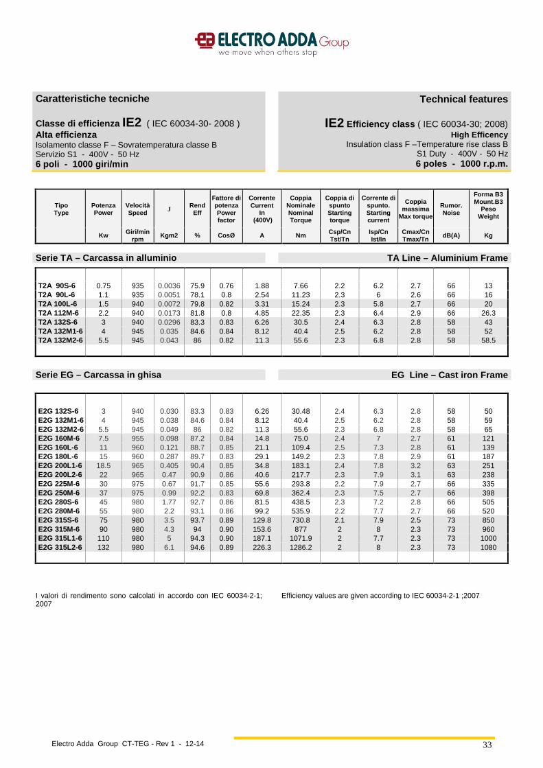
Electro Adda Group CT-TEG - Rev 1 - 12-14
33
Caratteristiche tecniche
Classe di efficienza IE2 ( IEC 60034-30- 2008 ) Alta efficienza Isolamento classe F – Sovratemperatura classe B Servizio S1 - 400V - 50 Hz 6 poli - 1000 giri/min
Technical features
IE2 Efficiency class ( IEC 60034-30; 2008) High Efficency
Insulation class F –Temperature rise class B S1 Duty - 400V - 50 Hz 6 poles - 1000 r.p.m.
Tipo Type
Potenza Powe r
Velocità Speed J Rend
Eff
Fattore di potenza Power factor
Corrente Current
In (400V)
Coppia Nominale Nominal Torque
Coppia di spunto Starting torque
Corrente di spunto. Starting current
Coppia massima
Max torque
Rumor . Noise
Forma B3 Mount.B3
Peso Weight
Kw Giri/min rpm
Kgm2 % CosØ A Nm Csp/Cn Tst/Tn
Isp/Cn Ist/In
Cmax/Cn Tmax/Tn
dB(A) Kg
Serie T A – Carcassa in alluminio TA Line – Aluminium Frame
T2A 90S-6 0.75 935 0.0036 75.9 0.76 1.88 7.66 2.2 6.2 2.7 66 13 T2A 90L-6 1.1 935 0.0051 78.1 0.8 2.54 11.23 2.3 6 2.6 66 16 T2A 100L-6 1.5 940 0.0072 79.8 0.82 3.31 15.24 2.3 5.8 2.7 66 20 T2A 112M-6 2.2 940 0.0173 81.8 0.8 4.85 22.35 2.3 6.4 2.9 66 26.3 T2A 132S-6 3 940 0.0296 83.3 0.83 6.26 30.5 2.4 6.3 2.8 58 43 T2A 132M1-6 4 945 0.035 84.6 0.84 8.12 40.4 2.5 6.2 2.8 58 52 T2A 132M2-6 5.5 945 0.043 86 0.82 11.3 55.6 2.3 6.8 2.8 58 58.5
Serie EG – Carcassa in ghisa EG Line – Cast iron Frame
E2G 132S-6 3 940 0.030 83.3 0.83 6.26 30.48 2.4 6.3 2.8 58 50 E2G 132M1-6 4 945 0.038 84.6 0.84 8.12 40.4 2.5 6.2 2.8 58 59 E2G 132M2-6 5.5 945 0.049 86 0.82 11.3 55.6 2.3 6.8 2.8 58 65 E2G 160M-6 7.5 955 0.098 87.2 0.84 14.8 75.0 2.4 7 2.7 61 121 E2G 160L-6 11 960 0.121 88.7 0.85 21.1 109.4 2.5 7.3 2.8 61 139 E2G 180L-6 15 960 0.287 89.7 0.83 29.1 149.2 2.3 7.8 2.9 61 187 E2G 200L1-6 18.5 965 0.405 90.4 0.85 34.8 183.1 2.4 7.8 3.2 63 251 E2G 200L2-6 22 965 0.47 90.9 0.86 40.6 217.7 2.3 7.9 3.1 63 238 E2G 225M-6 30 975 0.67 91.7 0.85 55.6 293.8 2.2 7.9 2.7 66 335 E2G 250M-6 37 975 0.99 92.2 0.83 69.8 362.4 2.3 7.5 2.7 66 398 E2G 280S-6 45 980 1.77 92.7 0.86 81.5 438.5 2.3 7.2 2.8 66 505 E2G 280M-6 55 980 2.2 93.1 0.86 99.2 535.9 2.2 7.7 2.7 66 520 E2G 315S-6 75 980 3.5 93.7 0.89 129.8 730.8 2.1 7.9 2.5 73 850 E2G 315M-6 90 980 4.3 94 0.90 153.6 877 2 8 2.3 73 960 E2G 315L1-6 110 980 5 94.3 0.90 187.1 1071.9 2 7.7 2.3 73 1000 E2G 315L2-6 132 980 6.1 94.6 0.89 226.3 1286.2 2 8 2.3 73 1080
I valori di rendimento sono calcolati in accordo con IEC 60034-2-1; 2007
Efficiency values are given according to IEC 60034-2-1 ;2007
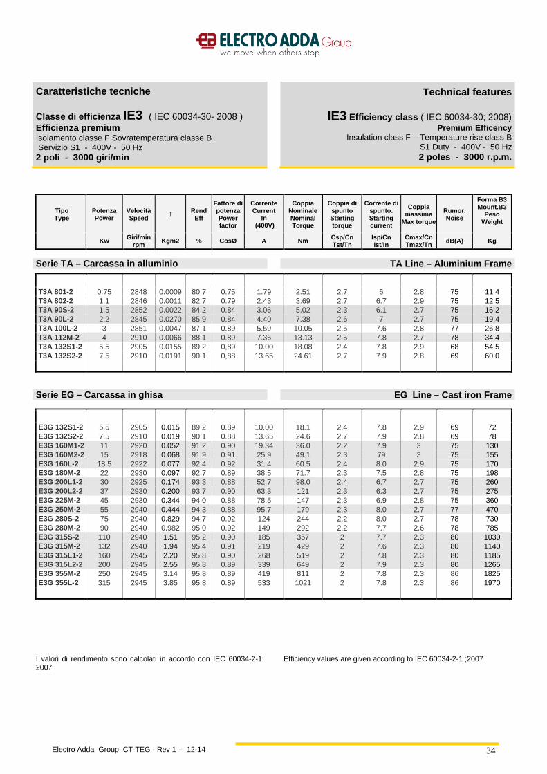
Electro Adda Group CT-TEG - Rev 1 - 12-14
34
Caratteristiche tecniche
Classe di efficienza IE3 ( IEC 60034-30- 2008 ) Efficienza premium Isolamento classe F Sovratemperatura classe B Servizio S1 - 400V - 50 Hz 2 poli - 3000 giri/min
Technical features
IE3 Efficiency class ( IEC 60034-30; 2008) Premium Efficency
Insulation class F – Temperature rise class B S1 Duty - 400V - 50 Hz 2 poles - 3000 r.p.m.
Tipo Type
Potenza Powe r
Velocità Speed J Rend
Eff
Fattore di potenza Power factor
Corrente Current
In (400V)
Coppia Nominale Nominal Torque
Coppia di spunto Starting torque
Corrente di spunto. Starting current
Coppia massima
Max torque
Rumor . Noise
Forma B3 Mount.B3
Peso Weight
Kw Giri/min rpm
Kgm2 % CosØ A Nm Csp/Cn Tst/Tn
Isp/Cn Ist/In
Cmax/Cn Tmax/Tn
dB(A) Kg
Serie T A – Carcassa in alluminio TA Line – Aluminium Frame
T3A 801-2 0.75 2848 0.0009 80.7 0.75 1.79 2.51 2.7 6 2.8 75 11.4 T3A 802-2 1.1 2846 0.0011 82.7 0.79 2.43 3.69 2.7 6.7 2.9 75 12.5 T3A 90S-2 1.5 2852 0.0022 84.2 0.84 3.06 5.02 2.3 6.1 2.7 75 16.2 T3A 90L-2 2.2 2845 0.0270 85.9 0.84 4.40 7.38 2.6 7 2.7 75 19.4 T3A 100L-2 3 2851 0.0047 87.1 0.89 5.59 10.05 2.5 7.6 2.8 77 26.8 T3A 112M-2 4 2910 0.0066 88.1 0.89 7.36 13.13 2.5 7.8 2.7 78 34.4 T3A 132S1-2 5.5 2905 0.0155 89,2 0,89 10.00 18.08 2.4 7.8 2.9 68 54.5 T3A 132S2-2 7.5 2910 0.0191 90,1 0,88 13.65 24.61 2.7 7.9 2.8 69 60.0
Serie EG – Carcassa in ghisa EG Line – Cast iron Frame
E3G 132S1-2 5.5 2905 0.015 89.2 0.89 10.00 18.1 2.4 7.8 2.9 69 72 E3G 132S2-2 7.5 2910 0.019 90.1 0.88 13.65 24.6 2.7 7.9 2.8 69 78 E3G 160M1-2 11 2920 0.052 91.2 0.90 19.34 36.0 2.2 7.9 3 75 130 E3G 160M2-2 15 2918 0.068 91.9 0.91 25.9 49.1 2.3 79 3 75 155 E3G 160L-2 18.5 2922 0.077 92.4 0.92 31.4 60.5 2.4 8.0 2.9 75 170 E3G 180M-2 22 2930 0.097 92.7 0.89 38.5 71.7 2.3 7.5 2.8 75 198 E3G 200L1-2 30 2925 0.174 93.3 0.88 52.7 98.0 2.4 6.7 2.7 75 260 E3G 200L2-2 37 2930 0.200 93.7 0.90 63.3 121 2.3 6.3 2.7 75 275 E3G 225M-2 45 2930 0.344 94.0 0.88 78.5 147 2.3 6.9 2.8 75 360 E3G 250M-2 55 2940 0.444 94.3 0.88 95.7 179 2.3 8.0 2.7 77 470 E3G 280S-2 75 2940 0.829 94.7 0.92 124 244 2.2 8.0 2.7 78 730 E3G 280M-2 90 2940 0.982 95.0 0.92 149 292 2.2 7.7 2.6 78 785 E3G 315S-2 110 2940 1.51 95.2 0.90 185 357 2 7.7 2.3 80 1030 E3G 315M-2 132 2940 1.94 95.4 0.91 219 429 2 7.6 2.3 80 1140 E3G 315L1-2 160 2945 2.20 95.8 0.90 268 519 2 7.8 2.3 80 1185 E3G 315L2-2 200 2945 2.55 95.8 0.89 339 649 2 7.9 2.3 80 1265 E3G 355M-2 250 2945 3.14 95.8 0.89 419 811 2 7.8 2.3 86 1825 E3G 355L-2 315 2945 3.85 95.8 0.89 533 1021 2 7.8 2.3 86 1970
I valori di rendimento sono calcolati in accordo con IEC 60034-2-1; 2007
Efficiency values are given according to IEC 60034-2-1 ;2007

Electro Adda Group CT-TEG - Rev 1 - 12-14
35
Caratteristiche tecniche
Classe di efficienza IE3 ( IEC 60034-30- 2008 ) Efficienza Premium Isolamento classe F – Sovratemperature di classe B Servizio S1 - 400V - 50 Hz 4 poli - 1500 giri/min
Technical features
IE3 Efficiency class ( IEC 60034-30; 2008) Premium Efficency
Insulation class F – Temperature rise class B S1 Duty - 400V - 50 Hz 4 poles - 1500 r.p.m.
Tipo Type
Potenza Powe r
Velocità Speed J
Rend Eff
Fattore di potenza Power factor
Corrente Current
In (400V)
Coppia Nominale Nominal Torque
Coppia di spunto Starting torque
Corrente di spunto. Starting current
Coppia massima
Max torque
Rumor . Noise
Forma B3 Mount.B3
Peso Weight
Kw Giri/min rpm
Kgm2 % CosØ A Nm Csp/Cn Tst/Tn
Isp/Cn Ist/In
Cmax/Cn Tmax/Tn
dB(A) Kg
Serie T A – Carcassa in alluminio TA Line – Aluminium Frame
T3A 802-4 0.75 1420 0.0023 82.5 0.76 1.73 5.04 2.3 5.4 2.9 70 12.6 T3A 90S-4 1.1 1425 0.00335 84.1 0.78 2.42 7.37 2.3 5.9 2.7 70 17.2 T3A 90L-4 1.5 1420 0.0042 85.3 0.79 3.21 10.09 2.4 6.4 2.7 70 21.6 T3A 100L1-4 2.2 1430 0.00805 86.7 0.82 4.47 14.7 2.4 6.6 2.9 70 28.9 T3A 100L2-4 3 1430 0.00955 87.7 0.80 6.17 20.0 2.4 6.9 2.8 70 31.6 T3A 112M-4 4 1435 0.0126 88.6 0.79 8.25 26.6 2.5 7.9 3 73 42.2 T3A 132S-4 5.5 1430 0.0317 89.6 0.82 10.81 36.73 2.3 7.1 2.8 63 59.3 T3A 132M-4 7.5 1430 0.0389 90.4 0.83 14.43 50.08 2.3 7.8 2.7 63 74.8
Serie EG – Carcassa in ghisa EG Line – Cast iron Frame
E3G 132S-4 5.5 1430 0.034 89.6 0.82 10.81 36.7 2.3 7.1 2.8 63 73 E3G 132M-4 7.5 1430 0.044 90.4 0.83 14.43 50.1 2.3 7.8 2.7 63 90 E3G 160M-4 11 1440 0.097 91.4 0.91 19.1 73.0 2.5 7.9 2.8 67 137 E3G 160L-4 15 1445 0.121 92.1 0.92 25.6 99.1 2.4 7.8 2.9 67 151 E3G 180M-4 18.5 1445 0.155 92.6 0.87 33.2 122 2.4 7.8 3 67 175 E3G 180L-4 22 1460 0.194 93 0.89 38.4 144 2.3 7.5 3 67 203 E3G 200L-4 30 1460 0.287 93.6 0.88 52.6 196 2.4 7.9 2.7 70 270 E3G 225S-4 37 1470 0.578 93.9 0.80 71.1 240 2.4 6.7 2.7 70 340 E3G 225M-4 45 1480 0.653 94.2 0.80 86.2 290 2.3 7 2.8 70 390 E3G 250M-4 55 1480 0.765 94.6 0.88 95.4 355 2.4 7.4 2.7 70 480 E3G 280S-4 75 1480 1.887 95 0.91 125 484 2.2 7.5 2.6 73 670 E3G 280M-4 90 1480 2.183 95.2 0.92 148 581 2.2 7.7 2.6 73 723 E3G 315S-4 110 1480 3.72 95.4 0.90 185 710 2 7.8 2.3 77 1050 E3G 315M-4 132 1480 4.30 95.6 0.91 219 852 2 7.8 2.3 77 1185 E3G 315L1-4 160 1480 5.11 95.8 0.91 265 1032 2 7.9 2.3 77 1205 E3G 315L2-4 200 1480 6.17 96 0.90 334 1290 2 7.7 2.3 77 1360 E3G 355M-4 250 1480 7.64 96 0.89 422 1613 2 7.9 2.3 84 1840 E3G 355L-4 315 1480 9.34 96 0.90 526 2032 2 7.8 2.3 84 2120
I valori di rendimento sono calcolati in accordo con IEC 60034-2-1; 2007
Efficiency values are given according to IEC 60034-2-1 ;2007
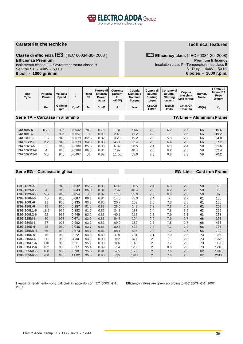
Electro Adda Group CT-TEG - Rev 1 - 12-14
36
Caratteristiche tecniche
Classe di efficienza IE3 ( IEC 60034-30- 2008 ) Efficienza Premium Isolamento classe F – Sovratemperatura classe B Servizio S1 - 400V - 50 Hz 6 poli - 1000 giri/min
Technical features
IE3 Efficiency class ( IEC 60034-30; 2008) Premium Efficency
Insulation class F –Temperature rise class B S1 Duty - 400V - 50 Hz 6 poles - 1000 r.p.m.
Tipo Type
Potenza Powe r
Velocità Speed J Rend
Eff
Fattore di potenza Power factor
Corrente Current
In (400V)
Coppia Nominale Nominal Torque
Coppia di spunto Starting torque
Corrente di spunto. Starting current
Coppia massima
Max torque
Rumor . Noise
Forma B3 Mount.B3
Peso Weight
Kw Giri/min rpm
Kgm2 % CosØ A Nm Csp/Cn Tst/Tn
Isp/Cn Ist/In
Cmax/Cn Tmax/Tn
dB(A) Kg
Serie T A – Carcassa in alluminio TA Line – Aluminium Frame
T3A 90S-6 0.75 935 0.0042 78.9 0.76 1.81 7.66 2.2 6.2 2.7 66 15.6 T3A 90L-6 1.1 935 0.0057 81 0.80 2.45 11.2 2.3 6 2.6 66 19.2 T3A 100L-6 1.5 940 0.0078 82.5 0.82 3.20 15.2 2.3 5.8 2.7 66 24.0 T3A 112M-6 2.2 940 0.0179 84.3 0.80 4.71 22.4 2.3 6.4 2.9 66 37.2 T3A 132S-6 3 940 0.0309 85.6 0.83 6.09 30.5 2.4 6.3 2.4 58 51.6 T3A 132M1-6 4 945 0.0389 86.8 0.84 7.92 40.4 2.5 6.2 2.5 58 62.4 T3A 132M2-6 5.5 945 0.0467 88 0.82 11.00 55.6 2.3 6.8 2.3 58 70.2
Serie EG – Carcassa in ghisa EG Line – Cast iron Frame
E3G 132S-6 3 940 0.032 85.6 0.83 6.09 30.5 2.4 6.3 2.8 58 63 E3G 132M1-6 4 945 0.043 86.8 0.84 7.92 40.4 2.5 6.2 2.8 58 75 E3G 132M2-6 5.5 945 0.054 88 0.82 11.0 55.6 2.3 6.8 2.8 58 82 E3G 160M-6 7.5 955 0.087 89.1 0.84 14.5 75.0 2.4 7 2.7 61 135 E3G 160L-6 11 960 0.135 90.3 0.85 20.7 109 2.5 7.3 2.8 61 155 E3G 180L-6 15 960 0.257 91.2 0.83 28.6 149 2.3 7.8 2.9 61 209 E3G 200L1-6 18.5 965 0.383 91.7 0.85 34.3 183 2.4 7.8 3.2 63 265 E3G 200L2-6 22 965 0.449 92.2 0.86 40.1 218 2.3 7.9 3.1 63 278 E3G 225M-6 30 975 0.671 92.9 0.85 54.8 294 2.2 7.9 2.7 66 375 E3G 250M-6 37 975 0.992 93.3 0.83 69.0 362 2.3 7.5 2.7 66 485 E3G 280S-6 45 980 2.046 93.7 0.86 80.6 438 2.3 7.2 2.8 66 735 E3G 280M1-6 55 980 2.573 94.1 0.86 98.1 536 2.2 7.7 2.7 66 790 E3G 315S-6 75 980 3.72 94.6 0.89 129 731 2.1 7.9 2.5 73 1050 E3G 315M-6 90 980 4.30 94.9 0.90 152 877 2 8 2.3 73 1075 E3G 315L1-6 110 980 5.11 95.1 0.90 186 1072 2 7.7 2.3 73 1120 E3G 315L2-6 132 980 6.17 95.4 0.89 224 1286 2 0.8 2.3 73 1210 E3G 355M1-6 160 980 8.98 95.6 0.91 265 1559 2 7.6 2.3 82 1940 E3G 355M2-6 200 980 11.02 95.8 0.90 335 1949 2 7.8 2.3 82 2017
I valori di rendimento sono calcolati in accordo con IEC 60034-2-1; 2007
Efficiency values are given according to IEC 60034-2-1 ;2007

Electro Adda Group CT-TEG - Rev 1 - 12-14
37
Caratteristiche tecniche Isolamento classe F Servizio S1 - 400V - 50 Hz
Technical features
Insulation class F Duty S1 - 400V - 50 Hz
Tipo Type
Potenza Powe r
Velocità Speed J Rend
Eff
Fattore di
potenza Power factor
Corrente Current
In (400V)
Coppia Nominale Nominal Torque
Coppia di Spunto
Start Torque
Corrente di spunto
Start Current
Coppia Massima
Max torque
Forma Mount.
B3 Peso
Weight
Kw Giri/min
rpm Kgm2 % CosØ A Nm Csp/Cn Tst/Tn
Isp/In Ist/In
Cmax/Cn Tmax/Tn Kg
2/4 poli - 3000/1500 giri/min 2/4 poles - 3000/1500 r.p.m.
TA 63 0.15/0.11 2680/1340 0.00024 54/53 0.82/0.67 0.49/0.45 0.53/0.58 1.7/1.5 4/3 1.8/1.6 4 TA 63 0.22/0.15 2690/1340 0.00029 61/59 0.86/0.67 0.61/0.55 1.7/1.4 1.7/1.5 4/3 1.8/1.6 4.6 TA 71 0.3/0.22 2760/1330 0.00035 60/55 0.8/0.73 0.9/0.79 1.04/1.56 1.7/1.5 3.5/3.5 1.9/1.6 6.4 TA 71 0.45/0.3 2790/1370 0.00052 63/58 0.8/0.73 1.29/1.02 1.54/2.08 2/1.8 4/4 2/1.7 7.5 TA 80 0.55/0.45 2820/1380 0.00120 65/64 0.84/0.75 1.45/1.35 1.88/3.11 2/1.8 4.5/4.5 2.1/1.8 8.9 TA 80 0.75/0.6 2830/1410 0.00170 67/68 0.86/0.77 1.9/1.65 2.56/4.1 1.8/1.7 4./4.55 2/1.8 10.9 TA 90S 1.25/0.95 2830/1380 0.00220 72/68 0.86/0.82 2.9/2.5 4.2/6.5 2/1.8 5/5 2/1.8 12.5 TA 90L 1.7/1.32 2840/1400 0.00280 73/70 0.86/0.83 3.9/3.3 5.74/9 2/1.8 5/5 2/1.8 15.7 TA 100L 2.4/1.84 2840/1400 0.00570 73/76 0.86/0.83 5.5/4.2 8.1/12.5 2/1.8 5.5/5 2/1.6 22 TA 100L 3.2/2.6 2850/1420 0.00780 74/78 0.86/0.85 7.5/5.7 11.1/17.8 2/1.9 5.5/5 2/1.9 23.5 TA 112M 4.5/4 2870/1420 0.00920 77/79 0.85/0.86 9.9/8.5 15/26.7 2/1.8 5.5/5 2.2/2 28.9 TA 132S 6/5 2870/1440 0.02100 79/82 0.84/0.86 13.05/10.2 20/33.2 2/1.5 5./55 2.2/1.9 45 TA 132M 8/6.6 2875/1440 0.02800 82/84 0.84/0.86 16.8/13.1 26.6/43.8 2/1.9 6/6 2.2/1.9 54
4/6 poli - 1500/1000 giri/min 4/6 poles - 1500/1000 r.p.m.
TA 71 0.22/0.15 1400/900 0.00129 52/45 0.70/0.68 0.87/0.71 1.5/1.59 1.8/1.9 3/2.7 1.9/1.8 6.9 TA 80 0.3/0.22 1400/910 0.00164 60/65 0.74/0.69 0.98/0.84 2.05/2.31 1.8/1.7 4.5/4 2/1.8 7.8 TA 80 0.45/0.3 1410/920 0.00256 63/58 0.75/0.7 1.37/1.07 3.05/3.11 1.8/1.7 4.5/4 2/1.8 11 TA 90S 0.66/0.45 1410/920 0.00354 66/61 0.76/0.65 1.9/1.64 4.47/4.67 1.7/1.6 5/4.5 2/1.7 14.7 TA 90L 0.88/0.6 1420/930 0.00505 70/64 0.77/0.67 2.36/2.02 5.92/6.16 1.7/1.6 5/4.5 2/1.9 15.9 TA 100L 1.32/0.88 1420/940 0.00870 72/67 0.85/0.75 3.11/2.3 8.88/8.94 1.8/1.7 6/5 2/1.8 21 TA100L 1.76/1.2 1430/950 0.01200 74/70 0.85/0.75 4.04/3.3 11.75/12.06 1.8/1.7 6/5 2/1.8 24 TA 112M 2.2/1.5 1430/950 0.01400 76/70 0.8/0.7 5.22/4.42 14.69/15 2/1.8 6/5 2.2/2 27.3 TA 132S 3.3/2.2 1440/960 0.03100 82/78 0.81/0.72 7.17/5.65 21.9/22.0 2/1.8 7/6 2.2/2.1 48 TA 132M 4.5/3 1450/970 0.04100 83/80 0.82/0.74 9.45/7.31 29.6/29.5 2/1.8 7/6 2.3/2.1 56
6/8 poli - 1000/750 giri/min 6/8 poles - 1000/750 r.p.m.
TA 71 0.11/0.075 900/680 0.00129 41/33 0.67/0.60 0.58/0.55 1.19/1.07 1.3/1.3 2/1.9 1.5/1.5 7 TA 80 0.18/0.11 900/680 0.00164 50/42 0.69/0.65 0.75/0.58 1.91/1.54 1.5/1.3 3.5/3 1.5/1.5 8.6 TA 80 0.25/0.18 920/700 0.00256 54/46 0.7/0.66 0.95/0.86 2.6/2.46 1.7/1.5 3.5/3 1.5/1.7 10.7 TA 90S 0.37/0.25 930/680 0.00354 58/50 0.72/0.68 1.28/1.06 3.8/3.51 1.5/1.4 4/3 1.8/1.8 11.8 TA 90L 0.55/0.37 940/685 0.00505 63/54 0.73/0.69 1.73/1.43 5.59/5.16 1.5/1.4 4/3 1.8/1.7 14.9 TA 100L 0.75/0.55 950/700 0.00870 69/63 0.74/0.74 2.12/1.7 7.54/7.5 1.5/1.4 5/4 4/2 21 TA 100L 1.03/0.75 955/705 0.01200 71/65 0.76/0.76 2.76/2.19 10.3/10.16 1.5/1.4 5/4 4/2 27 TA 112M 1.25/0.95 960/710 0.01400 72/64 0.71/0.71 3.53/3.02 12.43/12.78 1.6/1.4 5/4 2/1.8 28.9 TA 132S 2.2/1.5 970/720 0.03100 76/70 0.71/0.7 5.88/4.42 21.66/19.9 1.6/1.4 6/5.5 2.3/2 48.9 TA 132M 3/1.85 970/720 0.04100 78/74 0.71/0.7 7.82/5.01 29.54/24.37 1.6/1.4 6/5.5 2.3/2 58.6
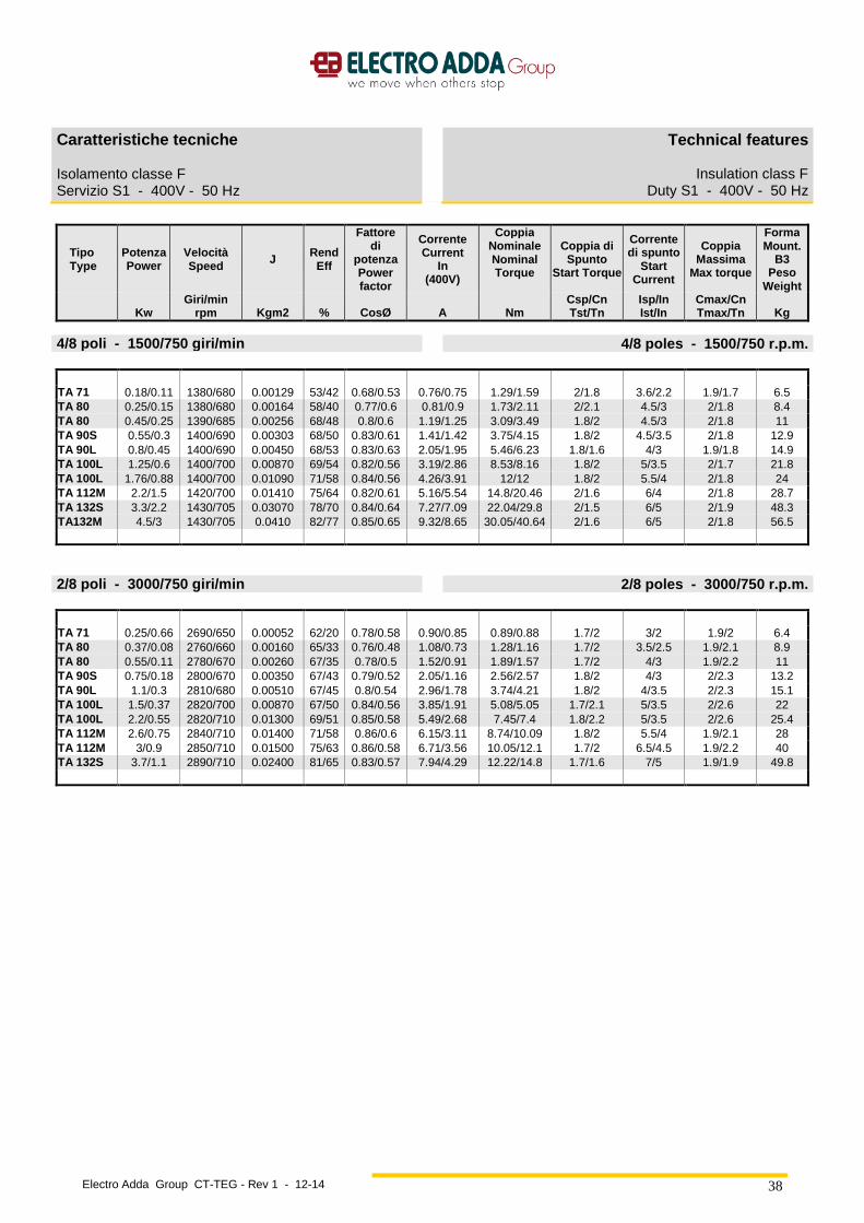
Electro Adda Group CT-TEG - Rev 1 - 12-14
38
Caratteristiche tecniche Isolamento classe F Servizio S1 - 400V - 50 Hz
Technical features
Insulation class F Duty S1 - 400V - 50 Hz
Tipo Type
Potenza Powe r
Velocità Speed J Rend
Eff
Fattore di
potenza Power factor
Corrente Current
In (400V)
Coppia Nominale Nominal Torque
Coppia di Spunto
Start Torque
Corrente di spunto
Start Current
Coppia Massima
Max torque
Forma Mount.
B3 Peso
Weight
Kw Giri/min
rpm Kgm2 % CosØ A Nm Csp/Cn Tst/Tn
Isp/In Ist/In
Cmax/Cn Tmax/Tn Kg
4/8 poli - 1500/750 giri/min 4/8 poles - 1500/750 r.p.m.
TA 71 0.18/0.11 1380/680 0.00129 53/42 0.68/0.53 0.76/0.75 1.29/1.59 2/1.8 3.6/2.2 1.9/1.7 6.5 TA 80 0.25/0.15 1380/680 0.00164 58/40 0.77/0.6 0.81/0.9 1.73/2.11 2/2.1 4.5/3 2/1.8 8.4 TA 80 0.45/0.25 1390/685 0.00256 68/48 0.8/0.6 1.19/1.25 3.09/3.49 1.8/2 4.5/3 2/1.8 11 TA 90S 0.55/0.3 1400/690 0.00303 68/50 0.83/0.61 1.41/1.42 3.75/4.15 1.8/2 4.5/3.5 2/1.8 12.9 TA 90L 0.8/0.45 1400/690 0.00450 68/53 0.83/0.63 2.05/1.95 5.46/6.23 1.8/1.6 4/3 1.9/1.8 14.9 TA 100L 1.25/0.6 1400/700 0.00870 69/54 0.82/0.56 3.19/2.86 8.53/8.16 1.8/2 5/3.5 2/1.7 21.8 TA 100L 1.76/0.88 1400/700 0.01090 71/58 0.84/0.56 4.26/3.91 12/12 1.8/2 5.5/4 2/1.8 24 TA 112M 2.2/1.5 1420/700 0.01410 75/64 0.82/0.61 5.16/5.54 14.8/20.46 2/1.6 6/4 2/1.8 28.7 TA 132S 3.3/2.2 1430/705 0.03070 78/70 0.84/0.64 7.27/7.09 22.04/29.8 2/1.5 6/5 2/1.9 48.3 TA132M 4.5/3 1430/705 0.0410 82/77 0.85/0.65 9.32/8.65 30.05/40.64 2/1.6 6/5 2/1.8 56.5
2/8 poli - 3000/750 giri/min 2/8 poles - 3000/750 r.p.m.
TA 71 0.25/0.66 2690/650 0.00052 62/20 0.78/0.58 0.90/0.85 0.89/0.88 1.7/2 3/2 1.9/2 6.4 TA 80 0.37/0.08 2760/660 0.00160 65/33 0.76/0.48 1.08/0.73 1.28/1.16 1.7/2 3.5/2.5 1.9/2.1 8.9 TA 80 0.55/0.11 2780/670 0.00260 67/35 0.78/0.5 1.52/0.91 1.89/1.57 1.7/2 4/3 1.9/2.2 11 TA 90S 0.75/0.18 2800/670 0.00350 67/43 0.79/0.52 2.05/1.16 2.56/2.57 1.8/2 4/3 2/2.3 13.2 TA 90L 1.1/0.3 2810/680 0.00510 67/45 0.8/0.54 2.96/1.78 3.74/4.21 1.8/2 4/3.5 2/2.3 15.1 TA 100L 1.5/0.37 2820/700 0.00870 67/50 0.84/0.56 3.85/1.91 5.08/5.05 1.7/2.1 5/3.5 2/2.6 22 TA 100L 2.2/0.55 2820/710 0.01300 69/51 0.85/0.58 5.49/2.68 7.45/7.4 1.8/2.2 5/3.5 2/2.6 25.4 TA 112M 2.6/0.75 2840/710 0.01400 71/58 0.86/0.6 6.15/3.11 8.74/10.09 1.8/2 5.5/4 1.9/2.1 28 TA 112M 3/0.9 2850/710 0.01500 75/63 0.86/0.58 6.71/3.56 10.05/12.1 1.7/2 6.5/4.5 1.9/2.2 40 TA 132S 3.7/1.1 2890/710 0.02400 81/65 0.83/0.57 7.94/4.29 12.22/14.8 1.7/1.6 7/5 1.9/1.9 49.8

Electro Adda Group CT-TEG - Rev 1 - 12-14
39
Alimentazione da inverter Inverter supply
I motori serie T ed EG sono previsti per alimentazione da inverter. Tali motori possono essere azionati fino alla frequenza nominale (50Hz) con tensione di alimentazione proporzionale alla frequenza. (Vedere diagr.1), alle frequenze maggiori possono essere alimentati a tensione costante fino a 80Hz
T and EG line motors are designed to be supplied by inverter. These motors can be driven up to the rated frequency (50Hz) with supply voltage proportional to the frequency. (See diagr.1), at higher frequencies they can be supplied at constant voltage up to the achievement of 80Hz
0
20
40
60
80
100
120
0 10 20 30 40 50 60 70 80 90 100
Frequenza di alimentazione (Hz)
Ten
sion
e di
alim
enta
zion
e in
% d
ella
nom
inal
e
Diagr. 1 - Diagramma tensione di alimentazione - frequenza.
Diagr. 1 - Supply voltage - frequency diagram.
Con il tipo di alimentazione indicata nel diagr. 1, il flusso creato dagli avvolgimenti statorici risulterà costante da 0 fino alla frequenza di 50 Hz, alle frequenze maggiori di 50 Hz il flusso risulterà inferiore al valore massimo Nota: Alle basse frequenze (0 ÷ 10 Hz) a causa delle cadute di tensione, per poter mantenere il flusso costante è necessario incrementare leggermente la tensione di alimentazione. Tale incremento di tensione dipende sia dal tipo di motore che dal tipo di inverter. I motori in esecuzione normale (autoventilati codice IC411) sono pertanto in grado di funzionare a coppia costante tra 40 e 50 Hz e a potenza costante nel tratto compreso tra 50 e 80 Hz (vedere diagramma 2 e 3 ). I motori a richiesta possono essere dotati di un ventilatore ausiliario ( codice IC 416 ), in tal caso possono fornire una coppia costante tra 0 e 50 Hz ed una potenza costante nel tratto compreso tra 50 e 80 Hz.
By the type of supply shown in diagr. 1, the flux created by the stator windings will be constant from 0 frequency to 50 Hz frequency, at frequencies higher than 50 Hz, the flux will be lower than the maximum value. Note: At low frequencies (0 ÷ 10 Hz) due to the voltage drops, in order to keep the flux constant, the supply voltage should be slightly increased. This voltage increase depends both on the motor type and on the inverter type. Consequently motors in standard execution (self ventilating code IC411) are able to run at constant torque between 40 and 50 Hz and at constant power in the section included between 50 and 80 Hz (see diagram 2 and 3). Upon request, motors can be equipped with an auxiliary fan (code IC 416), in this case they can supply a constant torque between 0 and 50 Hz and a constant power in the section included between 50 and 80 Hz.
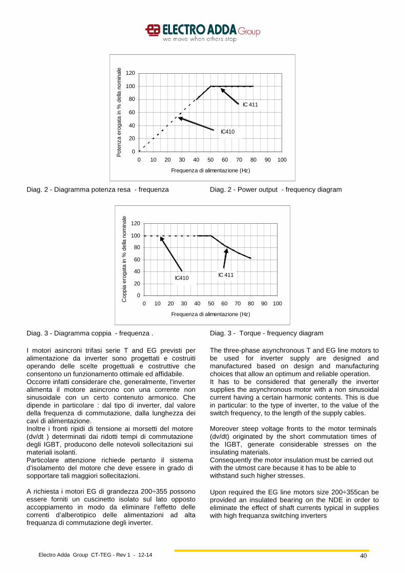
Electro Adda Group CT-TEG - Rev 1 - 12-14
40
0
20
40
60
80
100
120
0 10 20 30 40 50 60 70 80 90 100
Frequenza di alimentazione (Hz)
Pot
enza
ero
gata
in %
del
la n
omin
ale
IC 411
IC410
Diag. 2 - Diagramma potenza resa - frequenza Diag. 2 - Power output - frequency diagram
0
20
40
60
80
100
120
0 10 20 30 40 50 60 70 80 90 100
Frequenza di alimentazione (Hz)
Cop
pia
erog
ata
in %
del
la n
omin
ale
IC 411IC410
Diag. 3 - Diagramma coppia - frequenza . Diag. 3 - Torque - frequency diagram
I motori asincroni trifasi serie T and EG previsti per alimentazione da inverter sono progettati e costruiti operando delle scelte progettuali e costruttive che consentono un funzionamento ottimale ed affidabile. Occorre infatti considerare che, generalmente, l'inverter alimenta il motore asincrono con una corrente non sinusoidale con un certo contenuto armonico. Che dipende in particolare : dal tipo di inverter, dal valore della frequenza di commutazione, dalla lunghezza dei cavi di alimentazione. Inoltre i fronti ripidi di tensione ai morsetti del motore (dv/dt ) determinati dai ridotti tempi di commutazione degli IGBT, producono delle notevoli sollecitazioni sui materiali isolanti. Particolare attenzione richiede pertanto il sistema d’isolamento del motore che deve essere in grado di sopportare tali maggiori sollecitazioni. A richiesta i motori EG di grandezza 200÷355 possono essere forniti un cuscinetto isolato sul lato opposto accoppiamento in modo da eliminare l’effetto delle correnti d’alberotipico delle alimentazioni ad alta frequanza di commutazione degli inverter.
The three-phase asynchronous T and EG line motors to be used for inverter supply are designed and manufactured based on design and manufacturing choices that allow an optimum and reliable operation. It has to be considered that generally the inverter supplies the asynchronous motor with a non sinusoidal current having a certain harmonic contents. This is due in particular: to the type of inverter, to the value of the switch frequency, to the length of the supply cables. Moreover steep voltage fronts to the motor terminals (dv/dt) originated by the short commutation times of the IGBT, generate considerable stresses on the insulating materials. Consequently the motor insulation must be carried out with the utmost care because it has to be able to withstand such higher stresses. Upon required the EG line motors size 200÷355can be provided an insulated bearing on the NDE in order to eliminate the effect of shaft currents typical in supplies with high frequanza switching inverters
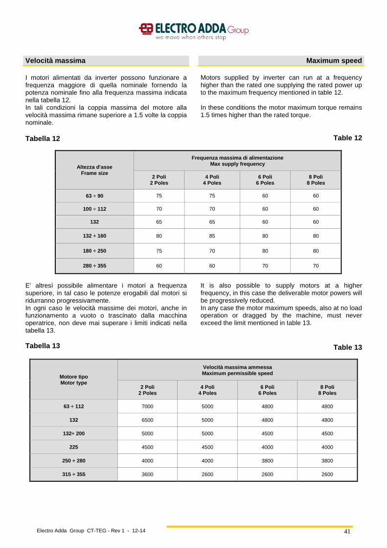
Electro Adda Group CT-TEG - Rev 1 - 12-14
41
Velocità massima Maximum speed
I motori alimentati da inverter possono funzionare a frequenza maggiore di quella nominale fornendo la potenza nominale fino alla frequenza massima indicata nella tabella 12. In tali condizioni la coppia massima del motore alla velocità massima rimane superiore a 1.5 volte la coppia nominale. Tabella 12
Motors supplied by inverter can run at a frequency higher than the rated one supplying the rated power up to the maximum frequency mentioned in table 12. In these conditions the motor maximum torque remains 1.5 times higher than the rated torque.
Table 12
Altezza d’asse Frame size
Frequenza massima di alimentazione Max supply frequency
2 Poli 2 Poles
4 Poli 4 Poles
6 Poli 6 Poles
8 Poli 8 Poles
63 ÷ 90 75 75 60 60
100 ÷ 112 70 70 60 60
132 65 65 60 60
132 ÷ 160 80 85 80 80
180 ÷ 250 75 70 80 80
280 ÷ 355 60 60 70 70
E’ altresì possibile alimentare i motori a frequenza superiore, in tal caso le potenze erogabili dal motori si ridurranno progressivamente. In ogni caso le velocità massime dei motori, anche in funzionamento a vuoto o trascinato dalla macchina operatrice, non deve mai superare i limiti indicati nella tabella 13. Tabella 13
It is also possible to supply motors at a higher frequency, in this case the deliverable motor powers will be progressively reduced. In any case the motor maximum speeds, also at no load operation or dragged by the machine, must never exceed the limit mentioned in table 13.
Table 13
Motore tipo Motor type
Velocità massima ammessa Maximum permissible speed
2 Poli 2 Poles
4 Poli 4 Poles
6 Poli 6 Poles
8 Poli 8 Poles
63 ÷ 112 7000 5000 4800 4800
132 6500 5000 4800 4800
132÷ 200 5000 5000 4500 4500
225 4500 4500 4000 4000
250 ÷ 280 4000 4000 3800 3800
315 ÷ 355 3600 2600 2600 2600

Electro Adda Group CT-TEG - Rev 1 - 12-14
42
Funzionamento a potenza aumentata Motori grandezze 63÷160
Increased power operation frame sizes 63÷160
I motori serie T ed EG (fino al grandezza 160) in esecuzione standard previsti per alimentazione a 230 V / 50 Hz con collegamento a triangolo, possono essere alimentati a frequenze maggiori di 50 Hz con tensione proporzionale alla frequenza fino a 100 Hz (2 volte la velocità nominale). In tal caso la potenza erogabile in servizio continuo (S1) può essere aumentata secondo quanto indicato nel diagr. 5. La corrente nel funzionamento a potenza nominale a 50 Hz aumenta di circa 1.73 volte il valore indicato nelle tabelle relativi ai dati tecnici a 400 Volt ; il valore di corrente assorbita alla potenza di 100 Hz varia in modo lineare. Ovviamente anche in questo caso non devono mai essere superati i limiti di velocità indicati alla tabelle dei dati tecnici.
T and EG line motors (up to size 160) in standard execution designed to be supplied at 230 V / 50 Hz with delta connection, may be supplied at frequencies higher than 50 Hz with voltage proportional to the frequency up to 100 Hz (twice the rated speed). In such case the motor output in continuous duty (S1) may be increased as shown in diagr.5. During operation at rated power at 50 Hz, current increases by approx. 1.73 times the value shown in the tables concerning the technical data at 400 Volt; the value of input current at the power of 100 Hz linearly changes. Of course also in this case the speed limits shown in the technical data tables must never be exceeded.
0
100
200
300
400
500
0 25 50 75 100
Frequenza di alimentazione (Hz)
Ten
sion
e di
alim
enta
zion
e
Diag. 4 - Diagramma tensione di alimentazione-frequenza previsto per i motori serie T e EG(230V/50Hz) per il funzionamento a potenza aumentata.
Diag. 4 – Supply voltage – frequency diagram intended for the T and EG line motors (230V/50Hz) for operation at increased power.
0
20
40
60
80
100
120
140
160
180
0 25 50 75 100
Frequenza di alimentazione (Hz)
Pot
enza
res
a in
% d
ella
nom
inal
e a
50H
z
Diag. 5 - Diagramma potenza resa - frequenza per i motori serie T a EG (220V/50Hz) per il funzionamento a potenza aumentata.
Diag. 5 - Power output – frequency diagram intended for the T and EG line motors (220V/50Hz) for operation at increased power.
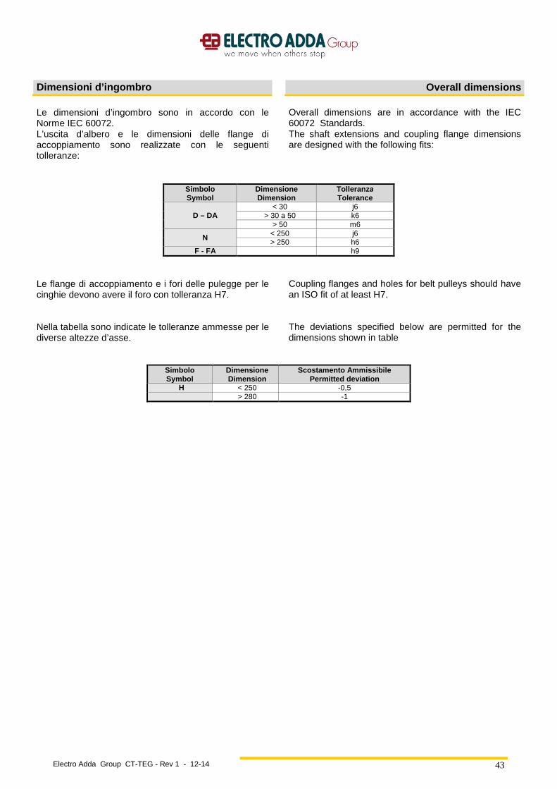
Electro Adda Group CT-TEG - Rev 1 - 12-14
43
Dimensioni d’ingombro Overall dimensions
Le dimensioni d’ingombro sono in accordo con le Norme IEC 60072. L’uscita d’albero e le dimensioni delle flange di accoppiamento sono realizzate con le seguenti tolleranze:
Overall dimensions are in accordance with the IEC 60072 Standards. The shaft extensions and coupling flange dimensions are designed with the following fits:
Simbolo Symbol
Dimensione Dimension
Tolleranza Tolerance
D – DA < 30 j6
> 30 a 50 k6 > 50 m6
N < 250 j6 > 250 h6
F - FA h9
Le flange di accoppiamento e i fori delle pulegge per le cinghie devono avere il foro con tolleranza H7. Nella tabella sono indicate le tolleranze ammesse per le diverse altezze d’asse.
Coupling flanges and holes for belt pulleys should have an ISO fit of at least H7. The deviations specified below are permitted for the dimensions shown in table
Simbolo Symbol
Dimensione Dimension
Scostamento Ammissibile Permitted deviation
H < 250 -0,5 > 280 -1
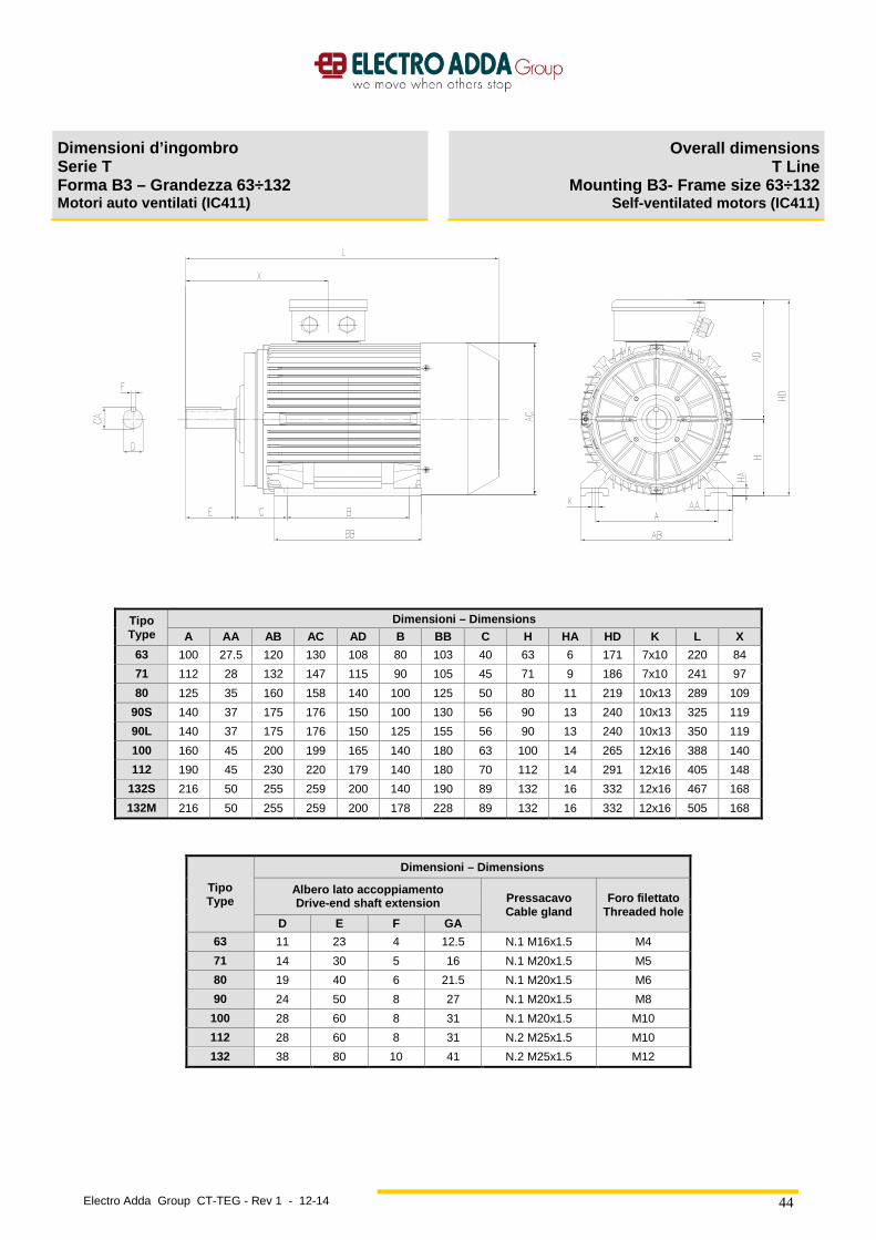
Electro Adda Group CT-TEG - Rev 1 - 12-14
44
Dimensioni d’ingombro Serie T Forma B3 – Grandezza 63÷132 Motori auto ventilati (IC411)
Overall dimensions T Line
Mounting B3- Frame size 63÷132 Self-ventilated motors (IC411)
Tipo Type
Dimensioni – Dimensions A AA AB AC AD B BB C H HA HD K L X
63 100 27.5 120 130 108 80 103 40 63 6 171 7x10 220 84
71 112 28 132 147 115 90 105 45 71 9 186 7x10 241 97
80 125 35 160 158 140 100 125 50 80 11 219 10x13 289 109
90S 140 37 175 176 150 100 130 56 90 13 240 10x13 325 119
90L 140 37 175 176 150 125 155 56 90 13 240 10x13 350 119
100 160 45 200 199 165 140 180 63 100 14 265 12x16 388 140
112 190 45 230 220 179 140 180 70 112 14 291 12x16 405 148
132S 216 50 255 259 200 140 190 89 132 16 332 12x16 467 168
132M 216 50 255 259 200 178 228 89 132 16 332 12x16 505 168
Tipo Type
Dimensioni – Dimensions
Albero lato accoppiamento Drive-end shaft extension Pressacavo
Cable gland Foro filettato
Threaded hole D E F GA
63 11 23 4 12.5 N.1 M16x1.5 M4
71 14 30 5 16 N.1 M20x1.5 M5
80 19 40 6 21.5 N.1 M20x1.5 M6
90 24 50 8 27 N.1 M20x1.5 M8
100 28 60 8 31 N.1 M20x1.5 M10
112 28 60 8 31 N.2 M25x1.5 M10
132 38 80 10 41 N.2 M25x1.5 M12
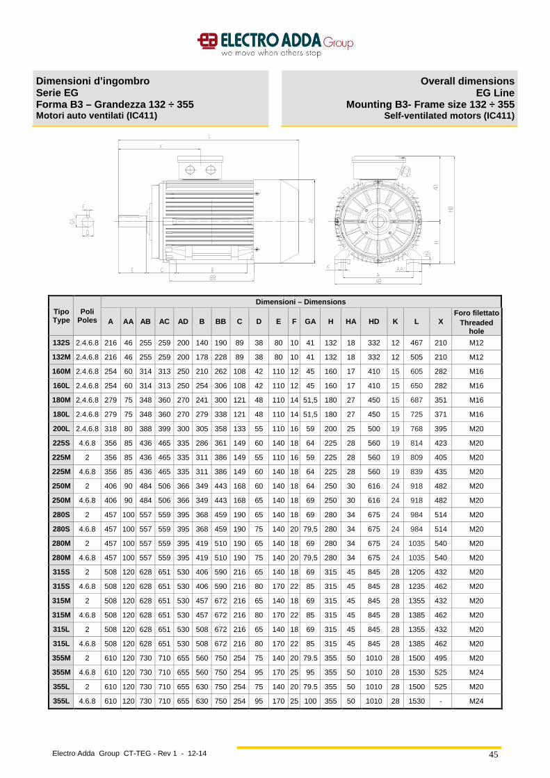
Electro Adda Group CT-TEG - Rev 1 - 12-14
45
Dimensioni d’ingombro Serie EG Forma B3 – Grandezza 132 ÷ 355 Motori auto ventilati (IC411)
Overall dimensions EG Line
Mounting B3- Frame size 132 ÷ 355 Self-ventilated motors (IC411)
Tipo Type
Poli Poles
Dimensioni – Dimensions
A AA AB AC AD B BB C D E F GA H HA HD K L X Foro filettato
Threaded hole
132S 2.4.6.8 216 46 255 259 200 140 190 89 38 80 10 41 132 18 332 12 467 210 M12
132M 2.4.6.8 216 46 255 259 200 178 228 89 38 80 10 41 132 18 332 12 505 210 M12
160M 2.4.6.8 254 60 314 313 250 210 262 108 42 110 12 45 160 17 410 15 605 282 M16
160L 2.4.6.8 254 60 314 313 250 254 306 108 42 110 12 45 160 17 410 15 650 282 M16
180M 2.4.6.8 279 75 348 360 270 241 300 121 48 110 14 51,5 180 27 450 15 687 351 M16
180L 2.4.6.8 279 75 348 360 270 279 338 121 48 110 14 51,5 180 27 450 15 725 371 M16
200L 2.4.6.8 318 80 388 399 300 305 358 133 55 110 16 59 200 25 500 19 768 395 M20
225S 4.6.8 356 85 436 465 335 286 361 149 60 140 18 64 225 28 560 19 814 423 M20
225M 2 356 85 436 465 335 311 386 149 55 110 16 59 225 28 560 19 809 405 M20
225M 4.6.8 356 85 436 465 335 311 386 149 60 140 18 64 225 28 560 19 839 435 M20
250M 2 406 90 484 506 366 349 443 168 60 140 18 64 250 30 616 24 918 482 M20
250M 4.6.8 406 90 484 506 366 349 443 168 65 140 18 69 250 30 616 24 918 482 M20
280S 2 457 100 557 559 395 368 459 190 65 140 18 69 280 34 675 24 984 514 M20
280S 4.6.8 457 100 557 559 395 368 459 190 75 140 20 79,5 280 34 675 24 984 514 M20
280M 2 457 100 557 559 395 419 510 190 65 140 18 69 280 34 675 24 1035 540 M20
280M 4.6.8 457 100 557 559 395 419 510 190 75 140 20 79,5 280 34 675 24 1035 540 M20
315S 2 508 120 628 651 530 406 590 216 65 140 18 69 315 45 845 28 1205 432 M20
315S 4.6.8 508 120 628 651 530 406 590 216 80 170 22 85 315 45 845 28 1235 462 M20
315M 2 508 120 628 651 530 457 672 216 65 140 18 69 315 45 845 28 1355 432 M20
315M 4.6.8 508 120 628 651 530 457 672 216 80 170 22 85 315 45 845 28 1385 462 M20
315L 2 508 120 628 651 530 508 672 216 65 140 18 69 315 45 845 28 1355 432 M20
315L 4.6.8 508 120 628 651 530 508 672 216 80 170 22 85 315 45 845 28 1385 462 M20
355M 2 610 120 730 710 655 560 750 254 75 140 20 79.5 355 50 1010 28 1500 495 M20
355M 4.6.8 610 120 730 710 655 560 750 254 95 170 25 95 355 50 1010 28 1530 525 M24
355L 2 610 120 730 710 655 630 750 254 75 140 20 79.5 355 50 1010 28 1500 525 M20
355L 4.6.8 610 120 730 710 655 630 750 254 95 170 25 100 355 50 1010 28 1530 - M24
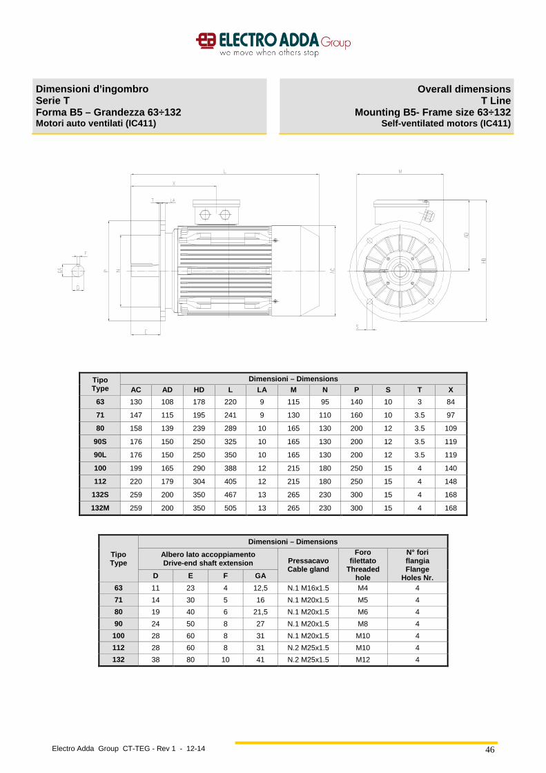
Electro Adda Group CT-TEG - Rev 1 - 12-14
46
Dimensioni d’ingombro Serie T Forma B5 – Grandezza 63÷132 Motori auto ventilati (IC411)
Overall dimensions T Line
Mounting B5- Frame size 63÷132 Self-ventilated motors (IC411)
Tipo Type
Dimensioni – Dimensions AC AD HD L LA M N P S T X
63 130 108 178 220 9 115 95 140 10 3 84
71 147 115 195 241 9 130 110 160 10 3.5 97
80 158 139 239 289 10 165 130 200 12 3.5 109
90S 176 150 250 325 10 165 130 200 12 3.5 119
90L 176 150 250 350 10 165 130 200 12 3.5 119
100 199 165 290 388 12 215 180 250 15 4 140
112 220 179 304 405 12 215 180 250 15 4 148
132S 259 200 350 467 13 265 230 300 15 4 168
132M 259 200 350 505 13 265 230 300 15 4 168
Tipo Type
Dimensioni – Dimensions Albero lato accoppiamento Drive-end shaft extension Pressacavo
Cable gland
Foro filettato
Threaded hole
N° fori flangia Flange
Holes Nr. D E F GA
63 11 23 4 12,5 N.1 M16x1.5 M4 4
71 14 30 5 16 N.1 M20x1.5 M5 4
80 19 40 6 21,5 N.1 M20x1.5 M6 4
90 24 50 8 27 N.1 M20x1.5 M8 4
100 28 60 8 31 N.1 M20x1.5 M10 4
112 28 60 8 31 N.2 M25x1.5 M10 4
132 38 80 10 41 N.2 M25x1.5 M12 4
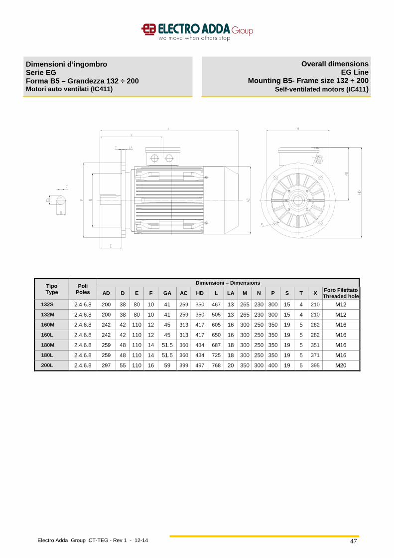
Electro Adda Group CT-TEG - Rev 1 - 12-14
47
Dimensioni d’ingombro Serie EG Forma B5 – Grandezza 132 ÷ 200 Motori auto ventilati (IC411)
Overall dimensions EG Line
Mounting B5- Frame size 132 ÷ 200 Self-ventilated motors (IC411 )
Tipo Type
Poli Poles
Dimensioni – Dimensions
AD D E F GA AC HD L LA M N P S T X Foro Filettato Threaded hole
132S 2.4.6.8 200 38 80 10 41 259 350 467 13 265 230 300 15 4 210 M12
132M 2.4.6.8 200 38 80 10 41 259 350 505 13 265 230 300 15 4 210 M12
160M 2.4.6.8 242 42 110 12 45 313 417 605 16 300 250 350 19 5 282 M16
160L 2.4.6.8 242 42 110 12 45 313 417 650 16 300 250 350 19 5 282 M16
180M 2.4.6.8 259 48 110 14 51.5 360 434 687 18 300 250 350 19 5 351 M16
180L 2.4.6.8 259 48 110 14 51.5 360 434 725 18 300 250 350 19 5 371 M16
200L 2.4.6.8 297 55 110 16 59 399 497 768 20 350 300 400 19 5 395 M20
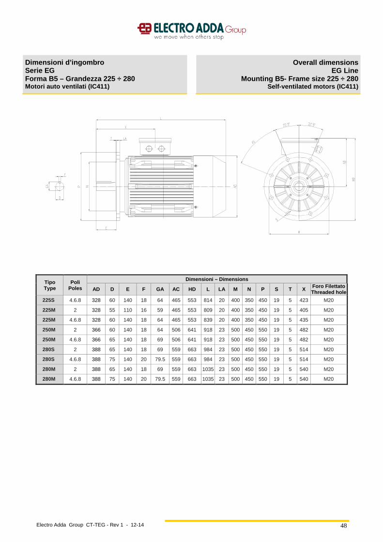
Electro Adda Group CT-TEG - Rev 1 - 12-14
48
Dimensioni d’ingombro Serie EG Forma B5 – Grandezza 225 ÷ 280 Motori auto ventilati (IC411)
Overall dimensions EG Line
Mounting B5- Frame size 225 ÷ 280 Self-ventilated motors (IC411)
Tipo Type
Poli Poles
Dimensioni – Dimensions
AD D E F GA AC HD L LA M N P S T X Foro Filettato Threaded hole
225S 4.6.8 328 60 140 18 64 465 553 814 20 400 350 450 19 5 423 M20
225M 2 328 55 110 16 59 465 553 809 20 400 350 450 19 5 405 M20
225M 4.6.8 328 60 140 18 64 465 553 839 20 400 350 450 19 5 435 M20
250M 2 366 60 140 18 64 506 641 918 23 500 450 550 19 5 482 M20
250M 4.6.8 366 65 140 18 69 506 641 918 23 500 450 550 19 5 482 M20
280S 2 388 65 140 18 69 559 663 984 23 500 450 550 19 5 514 M20
280S 4.6.8 388 75 140 20 79.5 559 663 984 23 500 450 550 19 5 514 M20
280M 2 388 65 140 18 69 559 663 1035 23 500 450 550 19 5 540 M20
280M 4.6.8 388 75 140 20 79.5 559 663 1035 23 500 450 550 19 5 540 M20
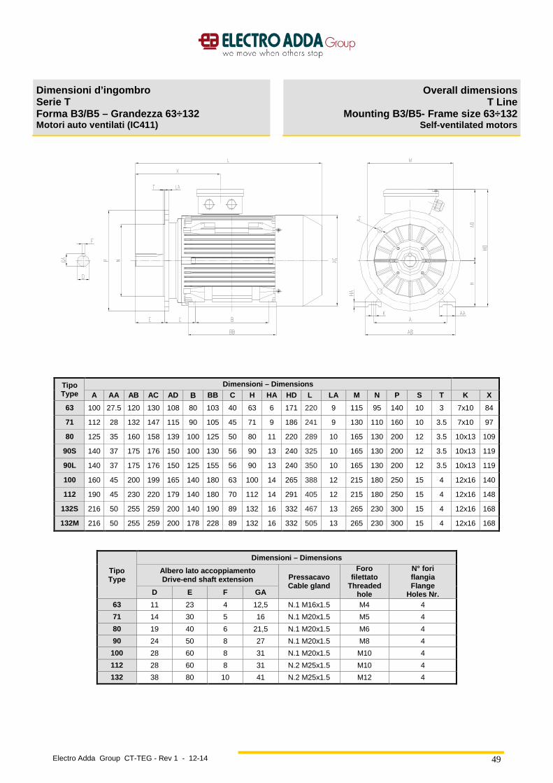
Electro Adda Group CT-TEG - Rev 1 - 12-14
49
Dimensioni d’ingombro Serie T Forma B3/B5 – Grandezza 63÷132 Motori auto ventilati (IC411)
Overall dimensions T Line
Mounting B3/B5- Frame size 63÷132 Self-ventilated motors
Tipo Type
Dimensioni – Dimensions
A AA AB AC AD B BB C H HA HD L LA M N P S T K X
63 100 27.5 120 130 108 80 103 40 63 6 171 220 9 115 95 140 10 3 7x10 84
71 112 28 132 147 115 90 105 45 71 9 186 241 9 130 110 160 10 3.5 7x10 97
80 125 35 160 158 139 100 125 50 80 11 220 289 10 165 130 200 12 3.5 10x13 109
90S 140 37 175 176 150 100 130 56 90 13 240 325 10 165 130 200 12 3.5 10x13 119
90L 140 37 175 176 150 125 155 56 90 13 240 350 10 165 130 200 12 3.5 10x13 119
100 160 45 200 199 165 140 180 63 100 14 265 388 12 215 180 250 15 4 12x16 140
112 190 45 230 220 179 140 180 70 112 14 291 405 12 215 180 250 15 4 12x16 148
132S 216 50 255 259 200 140 190 89 132 16 332 467 13 265 230 300 15 4 12x16 168
132M 216 50 255 259 200 178 228 89 132 16 332 505 13 265 230 300 15 4 12x16 168
Tipo Type
Dimensioni – Dimensions Albero lato accoppiamento Drive-end shaft extension Pressacavo
Cable gland
Foro filettato
Threaded hole
N° fori flangia Flange
Holes Nr. D E F GA
63 11 23 4 12,5 N.1 M16x1.5 M4 4
71 14 30 5 16 N.1 M20x1.5 M5 4
80 19 40 6 21,5 N.1 M20x1.5 M6 4
90 24 50 8 27 N.1 M20x1.5 M8 4
100 28 60 8 31 N.1 M20x1.5 M10 4
112 28 60 8 31 N.2 M25x1.5 M10 4
132 38 80 10 41 N.2 M25x1.5 M12 4
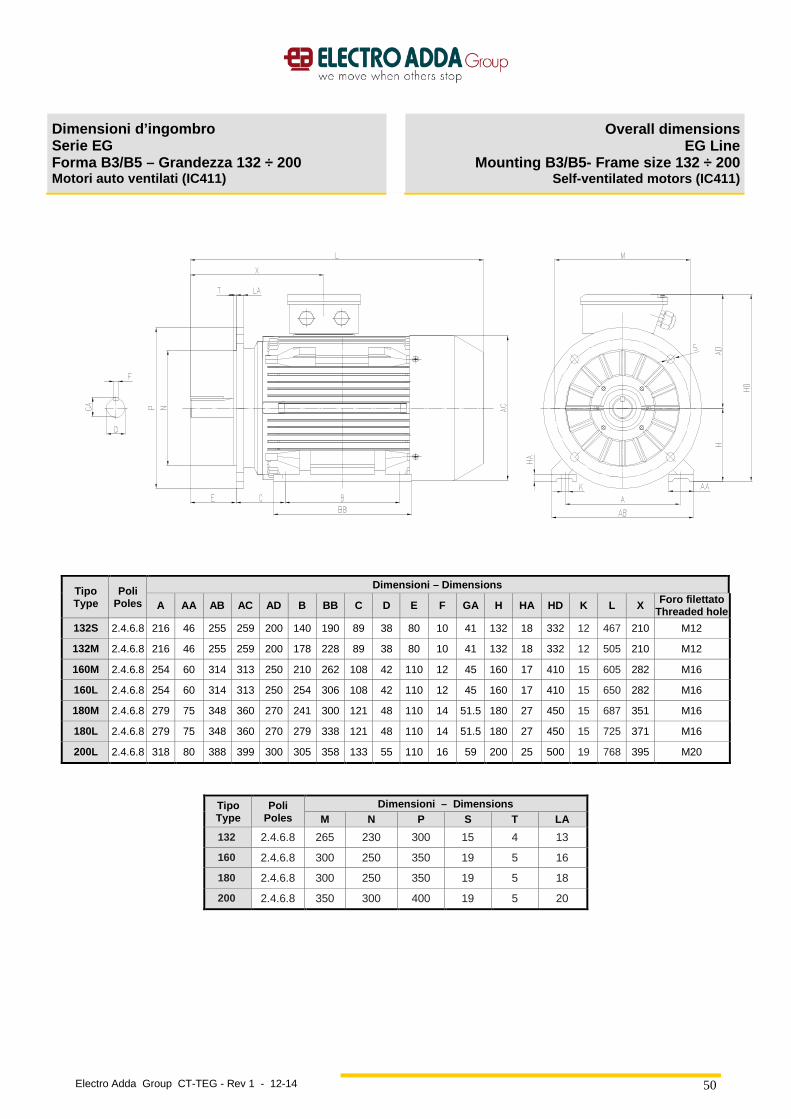
Electro Adda Group CT-TEG - Rev 1 - 12-14
50
Dimensioni d’ingombro Serie EG Forma B3/B5 – Grandezza 132 ÷ 200 Motori auto ventilati (IC411)
Overall dimensions EG Line
Mounting B3/B5- Frame size 132 ÷ 200 Self-ventilated motors (IC411)
Tipo Type
Poli Poles
Dimensioni – Dimensions
A AA AB AC AD B BB C D E F GA H HA HD K L X Foro filettato Threaded hole
132S 2.4.6.8 216 46 255 259 200 140 190 89 38 80 10 41 132 18 332 12 467 210 M12
132M 2.4.6.8 216 46 255 259 200 178 228 89 38 80 10 41 132 18 332 12 505 210 M12
160M 2.4.6.8 254 60 314 313 250 210 262 108 42 110 12 45 160 17 410 15 605 282 M16
160L 2.4.6.8 254 60 314 313 250 254 306 108 42 110 12 45 160 17 410 15 650 282 M16
180M 2.4.6.8 279 75 348 360 270 241 300 121 48 110 14 51.5 180 27 450 15 687 351 M16
180L 2.4.6.8 279 75 348 360 270 279 338 121 48 110 14 51.5 180 27 450 15 725 371 M16
200L 2.4.6.8 318 80 388 399 300 305 358 133 55 110 16 59 200 25 500 19 768 395 M20
Tipo Type
Poli Poles
Dimensioni – Dimensions M N P S T LA
132 2.4.6.8 265 230 300 15 4 13
160 2.4.6.8 300 250 350 19 5 16
180 2.4.6.8 300 250 350 19 5 18
200 2.4.6.8 350 300 400 19 5 20
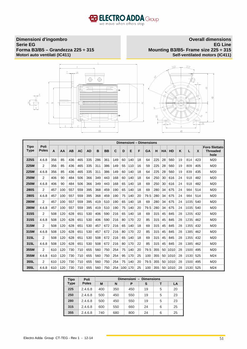
Electro Adda Group CT-TEG - Rev 1 - 12-14
51
Dimensioni d’ingombro Serie EG Forma B3/B5 – Grandezza 225 ÷ 315 Motori auto ventilati (IC411)
Overall dimensions EG Line
Mounting B3/B5- Frame size 225 ÷ 315 Self-ventilated motors (IC411)
Tipo Type
Poli Poles
Dimensioni – Dimensions
A AA AB AC AD B BB C D E F GA H HA HD K L X Foro filettato
Threaded hole
225S 4.6.8 356 85 436 465 335 286 361 149 60 140 18 64 225 28 560 19 814 423 M20
225M 2 356 85 436 465 335 311 386 149 55 110 16 59 225 28 560 19 809 405 M20
225M 4.6.8 356 85 436 465 335 311 386 149 60 140 18 64 225 28 560 19 839 435 M20
250M 2 406 90 484 506 366 349 443 168 60 140 18 64 250 30 616 24 918 482 M20
250M 4.6.8 406 90 484 506 366 349 443 168 65 140 18 69 250 30 616 24 918 482 M20
280S 2 457 100 557 559 395 368 459 190 65 140 18 69 280 34 675 24 984 514 M20
280S 4.6.8 457 100 557 559 395 368 459 190 75 140 20 79.5 280 34 675 24 984 514 M20
280M 2 457 100 557 559 395 419 510 190 65 140 18 69 280 34 675 24 1035 540 M20
280M 4.6.8 457 100 557 559 395 419 510 190 75 140 20 79.5 280 34 675 24 1035 540 M20
315S 2 508 120 628 651 530 406 590 216 65 140 18 69 315 45 845 28 1205 432 M20
315S 4.6.8 508 120 628 651 530 406 590 216 80 170 22 85 315 45 845 28 1235 462 M20
315M 2 508 120 628 651 530 457 672 216 65 140 18 69 315 45 845 28 1355 432 M20
315M 4.6.8 508 120 628 651 530 457 672 216 80 170 22 85 315 45 845 28 1385 462 M20
315L 2 508 120 628 651 530 508 672 216 65 140 18 69 315 45 845 28 1355 432 M20
315L 4.6.8 508 120 628 651 530 508 672 216 80 170 22 85 315 45 845 28 1385 462 M20
355M 2 610 120 730 710 655 560 750 254 75 140 20 79.5 355 50 1010 28 1500 495 M20
355M 4.6.8 610 120 730 710 655 560 750 254 95 170 25 100 355 50 1010 28 1530 525 M24
355L 2 610 120 730 710 655 560 750 254 75 140 20 79.5 355 50 1010 28 1500 495 M20
355L 4.6.8 610 120 730 710 655 560 750 254 100 170 25 100 355 50 1010 28 1530 525 M24
Tipo Type
Poli Poles
Dimensioni – Dimensions M N P S T LA
225 2.4.6.8 400 350 450 19 5 20
250 2.4.6.8 500 450 550 19 5 23
280 2.4.6.8 500 450 550 19 5 23
315 2.4.6.8 600 550 660 24 6 25
355 2.4.6.8 740 680 800 24 6 25
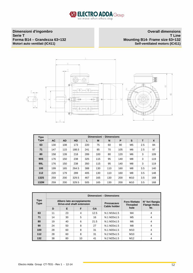
Electro Adda Group CT-TEG - Rev 1 - 12-14
52
Dimensioni d’ingombro Serie T Forma B14 – Grandezza 63÷132 Motori auto ventilati (IC411)
Overall dimensions T Line
Mounting B14- Frame size 63÷132 Self-ventilated motors (IC411)
Tipo Type
Dimensioni – Dimensions AC AD HD L M N P S T X
63 130 108 173 220 75 60 90 M5 2.5 84
71 147 115 188.5 241 85 70 105 M6 2.5 97
80 158 139 218 289 100 80 120 M6 3 109
90S 176 150 238 325 115 95 140 M8 3 119
90L 176 150 238 350 115 95 140 M8 3 119
100 199 165 264.5 388 130 110 160 M8 3.5 140
112 220 179 289 405 130 110 160 M8 3.5 148
132S 259 200 329.5 467 165 130 200 M10 3.5 168
132M 259 200 329.5 505 165 130 200 M10 3.5 168
Tipo Type
Dimensioni – Dimensions
Albero lato accoppiamento Drive-end shaft extension Pressacavo
Cable holder
Foro filettato Threaded
hole
N° fori flangia Flange Holes
Nr. D E F GA
63 11 23 4 12.5 N.1 M16x1.5 M4 4
71 14 30 5 16 N.1 M20x1.5 M5 4
80 19 40 6 21.5 N.1 M20x1.5 M6 4
90 24 50 8 27 N.1 M20x1.5 M8 4
100 28 60 8 31 N.1 M20x1.5 M10 4
112 28 60 8 31 N.2 M25x1.5 M10 4
132 38 80 10 41 N.2 M25x1.5 M12 4
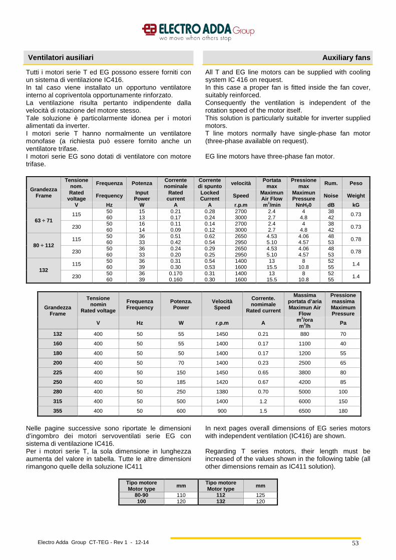
Electro Adda Group CT-TEG - Rev 1 - 12-14
53
Ventilatori ausiliari Auxiliary fans
Tutti i motori serie T ed EG possono essere forniti con un sistema di ventilazione IC416. In tal caso viene installato un opportuno ventilatore interno al copriventola opportunamente rinforzato. La ventilazione risulta pertanto indipendente dalla velocità di rotazione del motore stesso. Tale soluzione è particolarmente idonea per i motori alimentati da inverter. I motori serie T hanno normalmente un ventilatore monofase (a richiesta può essere fornito anche un ventilatore trifase. I motori serie EG sono dotati di ventilatore con motore trifase.
All T and EG line motors can be supplied with cooling system IC 416 on request. In this case a proper fan is fitted inside the fan cover, suitably reinforced. Consequently the ventilation is independent of the rotation speed of the motor itself. This solution is particularly suitable for inverter supplied motors. T line motors normally have single-phase fan motor (three-phase available on request). EG line motors have three-phase fan motor.
Grandezza Frame
Tensione nom. Frequenza Potenza Corrente
nominale Corrente di spunto velocità Portata
max Pressione
max Rum. Peso
Rated voltage Frequency Input
Power Rated
current Locked Current Speed Maximun
Air Flow Maximun Pressure Noise Weight
V Hz W A A r.p.m m3/min NnH20 dB kG
63 ÷ 71 115 50
60 15 13
0.21 0.17
0.28 0.24
2700 3000
2.4 2.7
4 4.8
38 42
0.73
230 50 60
16 14
0.11 0.09
0.14 0.12
2700 3000
2.4 2.7
4 4.8
38 42 0.73
80 ÷ 112 115 50
60 36 33
0.51 0.42
0.62 0.54
2650 2950
4.53 5.10
4.06 4.57
48 53 0.78
230 50 60
36 33
0.24 0.20
0.29 0.25
2650 2950
4.53 5.10
4.06 4.57
48 53
0.78
132 115
50 60
36 39
0.31 0.30
0.54 0.53
1400 1600
13 15.5
8 10.8
52 55 1.4
230 50 60
36 39
0.170 0.160
0.31 0.30
1400 1600
13 15.5
8 10.8
52 55
1.4
Grandezza Frame
Tensione nomin
Rated voltage
Frequenza Frequency
Potenza. Power
Velocità Speed
Corrente. nomimale
Rated current
Massima portata d’aria Maximun Air
Flow
Pressione massima Maximum Pressure
V Hz W r.p.m A m3/ora m3/h Pa
132 400 50 55 1450 0.21 880 70
160 400 50 55 1400 0.17 1100 40
180 400 50 50 1400 0.17 1200 55
200 400 50 70 1400 0.23 2500 65
225 400 50 150 1450 0.65 3800 80
250 400 50 185 1420 0.67 4200 85
280 400 50 250 1380 0.70 5000 100
315 400 50 500 1400 1.2 6000 150
355 400 50 600 900 1.5 6500 180
Nelle pagine successive sono riportate le dimensioni d’ingombro dei motori servoventilati serie EG con sistema di ventilazione IC416. Per i motori serie T, la sola dimensione in lunghezza aumenta del valore in tabella. Tutte le altre dimensioni rimangono quelle della soluzione IC411
In next pages overall dimensions of EG series motors with independent ventilation (IC416) are shown. Regarding T series motors, their length must be increased of the values shown in the following table (all other dimensions remain as IC411 solution).
Tipo motore Motor type
mm Tipo motore Motor type
mm
80-90 110 112 125 100 120 132 120
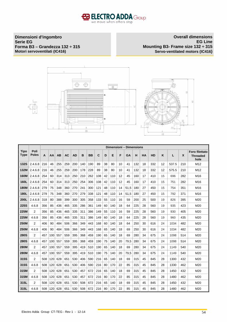
Electro Adda Group CT-TEG - Rev 1 - 12-14
54
Dimensioni d’ingombro Serie EG Forma B3 – Grandezza 132 ÷ 315 Motori servoventilati (IC416)
Overall dimensions EG Line
Mounting B3- Frame size 132 ÷ 315 Servo-ventilated motors (IC416 )
Tipo Type
Poli Poles
Dimensioni – Dimensions
A AA AB AC AD B BB C D E F GA H HA HD K L X Foro filettato
Threaded hole
132S 2.4.6.8 216 46 255 259 200 140 190 89 38 80 10 41 132 18 332 12 537.5 210 M12
132M 2.4.6.8 216 46 255 259 200 178 228 89 38 80 10 41 132 18 332 12 575.5 210 M12
160M 2.4.6.8 254 60 314 313 250 210 262 108 42 110 12 45 160 17 410 15 696 282 M16
160L 2.4.6.8 254 60 314 313 250 254 306 108 42 110 12 45 160 17 410 15 751 282 M16
180M 2.4.6.8 279 75 348 360 270 241 300 121 48 110 14 51,5 180 27 450 15 754 351 M16
180L 2.4.6.8 279 75 348 360 270 279 338 121 48 110 14 51,5 180 27 450 15 792 371 M16
200L 2.4.6.8 318 80 388 399 300 305 358 133 55 110 16 59 200 25 500 19 826 395 M20
225S 4.6.8 356 85 436 465 335 286 361 149 60 140 18 64 225 28 560 19 935 423 M20
225M 2 356 85 436 465 335 311 386 149 55 110 16 59 225 28 560 19 930 405 M20
225M 4.6.8 356 85 436 465 335 311 386 149 60 140 18 64 225 28 560 19 960 435 M20
250M 2 406 90 484 506 366 349 443 168 60 140 18 64 250 30 616 24 1034 482 M20
250M 4.6.8 406 90 484 506 366 349 443 168 65 140 18 69 250 30 616 24 1034 482 M20
280S 2 457 100 557 559 395 368 459 190 65 140 18 69 280 34 675 24 1098 514 M20
280S 4.6.8 457 100 557 559 395 368 459 190 75 140 20 79,5 280 34 675 24 1098 514 M20
280M 2 457 100 557 559 395 419 510 190 65 140 18 69 280 34 675 24 1149 540 M20
280M 4.6.8 457 100 557 559 395 419 510 190 75 140 20 79,5 280 34 675 24 1149 540 M20
315S 2 508 120 628 651 530 406 590 216 65 140 18 69 315 45 845 28 1300 432 M20
315S 4.6.8 508 120 628 651 530 406 590 216 80 170 22 85 315 45 845 28 1330 462 M20
315M 2 508 120 628 651 530 457 672 216 65 140 18 69 315 45 845 28 1450 432 M20
315M 4.6.8 508 120 628 651 530 457 672 216 80 170 22 85 315 45 845 28 1480 462 M20
315L 2 508 120 628 651 530 508 672 216 65 140 18 69 315 45 845 28 1450 432 M20
315L 4.6.8 508 120 628 651 530 508 672 216 80 170 22 85 315 45 845 28 1480 462 M20
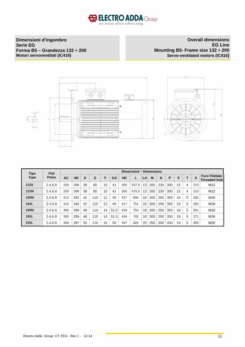
Electro Adda Group CT-TEG - Rev 1 - 12-14
55
Dimensioni d’ingombro Serie EG Forma B5 – Grandezza 132 ÷ 200 Motori servoventilati (IC416)
Overall dimensions EG Line
Mounting B5- Frame size 132 ÷ 200 Servo-ventilated motors (IC416 )
Tipo Type
Poli Poles
Dimensioni – Dimensions
AC AD D E F GA HD L LA M N P S T X Foro Filettato Threaded hole
132S 2.4.6.8 259 200 38 80 10 41 350 537.5 13 265 230 300 15 4 210 M12
132M 2.4.6.8 259 200 38 80 10 41 350 575.5 13 265 230 300 15 4 210 M12
160M 2.4.6.8 313 242 42 110 12 45 417 696 16 300 250 350 19 5 282 M16
160L 2.4.6.8 313 242 42 110 12 45 417 751 16 300 250 350 19 5 282 M16
180M 2.4.6.8 360 259 48 110 14 51.5 434 754 18 300 250 350 19 5 351 M16
180L 2.4.6.8 360 259 48 110 14 51.5 434 792 18 300 250 350 19 5 371 M16
200L 2.4.6.8 399 297 55 110 16 59 497 826 20 350 300 400 19 5 395 M20

Electro Adda Group CT-TEG - Rev 1 - 12-14
56
Dimensioni d’ingombro Serie EG Forma B5 – Grandezza 225 ÷ 315 Motori servoventilati (IC416)
Overall dimensions EG Line
Mounting B5- Frame size 225 ÷ 315 Servo-ventilated motors (IC416 )
Tipo Type
Poli Poles
Dimensioni – Dimensions
AC AD D E F GA HD L LA M N P S T X Foro Filettato Threaded hole
225S 4.6.8 465 328 60 140 18 64 553 935 20 400 350 450 19 5 423 M20
225M 2 465 328 55 110 16 59 553 930 20 400 350 450 19 5 405 M20
225M 4.6.8 465 328 60 140 18 64 553 960 20 400 350 450 19 5 435 M20
250M 2 506 366 60 140 18 64 641 1034 23 500 450 550 19 5 482 M20
250M 4.6.8 506 366 65 140 18 69 641 1034 23 500 450 550 19 5 482 M20
280S 2 559 388 65 140 18 69 663 1098 23 500 450 550 19 5 514 M20
280S 4.6.8 559 388 75 140 20 79.5 663 1098 23 500 450 550 19 5 514 M20
280M 2 559 388 65 140 18 69 663 1149 23 500 450 550 19 5 540 M20
280M 4.6.8 559 388 75 140 20 79.5 663 1149 23 500 450 550 19 5 540 M20
Electro Adda Group CT-TEG - Rev 1 - 12-14
57
ELECTRO ADDA S.p.A. Via Nazionale 8, Beverate di Brivio (LC) - I
Tel +39 039 53.20.621 Fax +39 039 53.21.335 www.electroadda.com [email protected]
Unità locale Modena: Via S. Anna 640, Modena - I
Tel +39 059 45.21.32 Fax +39 059 45.21.58 [email protected]
ADDA ANTRIEBSTECHNIK GMBH Max-Planck-Strasse 2, Rödermark - D
Tel +49 6074 91.050 Fax +49 6074 91.0520 [email protected]