Montaggio CDI 12 VOLT - catalog.polini.comcatalog.polini.com/dep/PI_483.pdf · provvede a generare...
20
Montaggio CDI 12 VOLT Sicurezza La CDI Polini 12 volt è un dispositivo elettronico il cui impiego è strettamente limitato al settore delle competizioni motoristiche sportive su circuito chiuso. Non può essere impiegato in campi diversi da quello per cui è stato concepito. Deve essere utilizzato solo da persone con adeguata conoscenza tecnica e con una buona capacità di valutazione dei rischi. Impostazioni inadeguate senza valutarne le conseguenze possono causare danni al motore e quindi mettere in pericolo la vita delle persone. Chi guida il mezzo sul quale è installata la CDI deve essere messo a conoscenza dei rischi che impostazioni errate possono comportare. Toccare il dispositivo e i suoi cablaggi solo con l’utilizzo di guanti isolanti, oppure dopo 10 minuti lo spegnimento del motore. Collegamenti errati possono dare scosse elettriche inaspettate. Persone con problemi cardiaci non devono utilizzare-installare la CDI Polini 12 volt. Precauzioni Per far funzionare correttamente questo sistema è necessario premunirsi di una batteria. Fate attenzione che la batteria a 12 volt deve avere almeno 4/6 A/h. Naturalmente più la batteria è potente, maggiore sarà la durata. Fate attenzione ai giri motore, più i giri motore sono alti più la centralina consuma. Per avere un riferimento potete calcolare che a 12000 giri motore si ha un consumo di circa 0.7A/h. Con batteria in buono stato di carica ed efficienza ottimale si possono superare tranquillamente le 4 ore di funzionamento. Descrizione del dispositivo. La CDI è programmabile e dotata di diverse possibilità di utilizzo e impostazione. Nella sua versione base provvede a generare una curva d’accensione da 600 Rpm a 20000 Rpm, a passi di 100 Rpm ed a risoluzione dell’angolo anticipo accensione di 0.2°. Schema di collegamento. La CDI è molto semplice da montare, basta seguire queste piccole indicazioni: 1) collegare il cablaggio alla CDI 2) collegare il Pick up al suo connettore 3) collegare i cavi di massa neri; uno va collegato alla massa della batteria, l’altro deve andare a massa al telaio, e il telaio deve essere a massa col motore e con la bobina. 4) collegare la bobina 5) montare il supporto pick-up 6) montare il volano di fase pick-up e controllare in traferro 0.8/1 mm Fate molta attenzione non controllate mai in traferro con la CDI accesa collegata alla centralina, la CDI va in corto e può bruciare in nessun caso ci sarà garanzia se la centralina sarà bruciata da un cortocircuito. 7) Il collegamento +12 deve essere collegato per ultimo. Noterete che il collegamento è stato interrotto perché il +12 deve essere messo sotto un interruttore per interrompere l’alimentazione alla CDI e per spegnere il motore quando è acceso. Regolazione anticipo La regolazione anticipo in queste CDI è una curva per scooter 70 cc EVOLUTION Tarare con stroboscopica a 30/32 gradi a 4000 rpm. Oppure con il comparatore a 4 mm con la camma in uscita (come da foto 1). Per modificare angolo fisso di anticipo e curva caricare il “Programmer POLINI 2013” Leggere attentamente istruzioni nel cd e controllare se il vostro pc ha un sistema operativo compatibile.
-
Upload
duongxuyen -
Category
Documents
-
view
223 -
download
0
Transcript of Montaggio CDI 12 VOLT - catalog.polini.comcatalog.polini.com/dep/PI_483.pdf · provvede a generare...

Montaggio CDI 12 VOLT Sicurezza La CDI Polini 12 volt è un dispositivo elettronico il cui impiego è strettamente limitato al settore delle competizioni motoristiche sportive su circuito chiuso. Non può essere impiegato in campi diversi da quello per cui è stato concepito. Deve essere utilizzato solo da persone con adeguata conoscenza tecnica e con una buona capacità di valutazione dei rischi. Impostazioni inadeguate senza valutarne le conseguenze possono causare danni al motore e quindi mettere in pericolo la vita delle persone. Chi guida il mezzo sul quale è installata la CDI deve essere messo a conoscenza dei rischi che impostazioni errate possono comportare. Toccare il dispositivo e i suoi cablaggi solo con l’utilizzo di guanti isolanti, oppure dopo 10 minuti lo spegnimento del motore. Collegamenti errati possono dare scosse elettriche inaspettate. Persone con problemi cardiaci non devono utilizzare-installare la CDI Polini 12 volt. Precauzioni Per far funzionare correttamente questo sistema è necessario premunirsi di una batteria. Fate attenzione che la batteria a 12 volt deve avere almeno 4/6 A/h. Naturalmente più la batteria è potente, maggiore sarà la durata. Fate attenzione ai giri motore, più i giri motore sono alti più la centralina consuma. Per avere un riferimento potete calcolare che a 12000 giri motore si ha un consumo di circa 0.7A/h. Con batteria in buono stato di carica ed efficienza ottimale si possono superare tranquillamente le 4 ore di funzionamento. Descrizione del dispositivo. La CDI è programmabile e dotata di diverse possibilità di utilizzo e impostazione. Nella sua versione base provvede a generare una curva d’accensione da 600 Rpm a 20000 Rpm, a passi di 100 Rpm ed a risoluzione dell’angolo anticipo accensione di 0.2°. Schema di collegamento. La CDI è molto semplice da montare, basta seguire queste piccole indicazioni: 1) collegare il cablaggio alla CDI 2) collegare il Pick up al suo connettore 3) collegare i cavi di massa neri; uno va collegato alla massa della batteria, l’altro deve andare a massa al telaio, e il telaio deve essere a massa col motore e con la bobina. 4) collegare la bobina 5) montare il supporto pick-up 6) montare il volano di fase pick-up e controllare in traferro 0.8/1 mm Fate molta attenzione non controllate mai in traferro con la CDI accesa collegata alla centralina, la CDI va in corto e può bruciare in nessun caso ci sarà garanzia se la centralina sarà bruciata da un cortocircuito. 7) Il collegamento +12 deve essere collegato per ultimo. Noterete che il collegamento è stato interrotto perché il +12 deve essere messo sotto un interruttore per interrompere l’alimentazione alla CDI e per spegnere il motore quando è acceso. Regolazione anticipo La regolazione anticipo in queste CDI è una curva per scooter 70 cc EVOLUTION Tarare con stroboscopica a 30/32 gradi a 4000 rpm. Oppure con il comparatore a 4 mm con la camma in uscita (come da foto 1). Per modificare angolo fisso di anticipo e curva caricare il “Programmer POLINI 2013” Leggere attentamente istruzioni nel cd e controllare se il vostro pc ha un sistema operativo compatibile.

Montaggio per motori Piaggio
FOTO 1
Montaggio per Yamaha orizzontale
(consigliato per motori Big Evolution 70 cc)
Montaggio per Yamaha orizzontale (consigliato per motori Big Evolution 94 cc)
SENSO DI
ROTAZIONE
ANGOLO FISSO
ANGOLO FISSO
M5 x 35
M6x20
bloccare i pioli originali con frena
filetti forte
rondella 6x11
(grower)
massa d'inerzia
aggiuntiva
M6x16
Rondella alluminio spessore 3 mm.

Descrizione � Filo ROSSO CDI che diventa ROSSO/BLU nel cablaggio: è il segnale di fase dell’impulsore o pick-up. Esso va collegato al pick-up. Se il pick-up è un modello a 2 fili, collegare l’altro terminale a massa. E' buona norma fissare il filo rosso, così come gli altri, lontano dalla bobina e dal cavo candela. � Filo VERDE: è il pilotaggio della bobina; esso va collegato al polo della bobina. Scollegare questo cavo durante il funzionamento può danneggiare la centralina, quindi se ne consiglia un fissaggio affidabile. Se si usa una bobina a 2 poli (o 2 faston) il polo non occupato dal verde deve essere messo a massa. Non utilizzare pulsanti di spegnimento su questo filo. � Filo MARRONE che diventa ROSSO/MARRONE nel cablaggio: è l’alimentazione a +12Volt che fornisce energia alla centralina. Si può usare un fusibile da 2 Ampere in serie a questo filo per proteggere il proprio mezzo dai rischi di incendio che un’eventuale avaria può causare. Per spegnere il motore, scollegare questo filo. � Filo BLU che diventa NERO nel cablaggio: è il negativo a -12Volt e deve essere collegato al polo negativo della batteria. Da notare che il filo negativo dovrà essere presente anche sul polo negativo della bobina, sul carter motore ed eventualmente anche sul telaio, se la bobina è fissata al telaio. Accorgimenti elettrici necessari. Tenere la CDI lontano dalla bobina poiché essa può arrecare disturbo al regolare funzionamento. I fili elettrici della centralina non devono scorrere appaiati al cavo candela, ma il più lontano possibile. Non utilizzare candele resistive; regolare la distanza dagli elettrodi della candela usata a 0.4 mm. Fissaggio meccanico del dispositivo. La CDI deve essere fissata saldamente ad un punto del mezzo in cui non vi siano intense vibrazioni o temperature troppo elevate.

Requisiti del sistema operativo per programma centralina “Programmer POLINI 2013” è concepito per l'uso su sistemi operativi Microsoft® Windows partendo da Xp sino a Windows 7 e 8: non si esclude però la compatibilità con sistemi operativi successivi, ma al momento attuale non è ancora stata pienamente testata. Il PC sul quale lo si intende installare deve essere almeno P4, 512 MB Ram, lettore CD rom-DVD funzionante, 200 MB liberi su Hard Disk, una porta USB libera e funzionante. La risoluzione ottimale per una corretta visualizzazione è 1024X768, ma funziona ovviamente anche con risoluzioni superiori. Il PC deve essere esente da Virus o altro malware.

Manuale operativo software “Programmer 2013” Sicurezza. Regolazioni improprie su dispositivi eseguite tramite software “Programmer 2013” possono essere pericolose e pertanto mettere in pericolo l'integrità fisica delle persone o creare danneggiamenti su motori e mezzi. Pertanto tali interventi devono essere messi in atto solo da persone competenti e solo dopo aver effettuato un'attenta valutazione degli eventuali pericoli che esse comportano. Non si assume pertanto la responsabilità per danneggiamenti ed infortuni derivanti da impostazioni eseguite in maniera errata. Utilizzo del software. “Programmer 2013” è un programma che permette la modifica o la personalizzazione delle impostazioni-dati. Copyright. “Programmer 2013” non è un prodotto freeware, non è gratuito, ed è soggetto alle leggi anti-pirateria vigenti. Ne è proibita pertanto la riproduzione e l'uso se non autorizzati. Ne è consentito l'uso solo in abbinamento ad un dispositivo “Polini” a cui è associato. Non si assume la responsabilità di malfunzionamenti, perdite di dati, avarie al proprio PC o al proprio mezzo. Chi lo utilizza lo fa a proprio rischio e pericolo. La riproduzione di questo manuale, anche parziale, è vietata. Requisiti del sistema. “Programmer 2013” è concepito per l'uso su sistemi operativi Microsoft® Windows partendo da Xp sino a Windows 7-8: non si esclude però la compatibilità' con sistemi operativi successivi, ma al momento attuale non è ancora stata pienamente testata. Il PC sul quale lo si intende installare deve essere almeno P4, 512 MB Ram, lettore CD rom-DVD funzionante, 200 MB liberi su Hard Disk, una porta USB libera e funzionante. La risoluzione ottimale per una corretta visualizzazione è 1024X768, ma funziona ovviamente anche con risoluzioni superiori. Il PC deve essere esente da Virus o altro malware. Installazione Driver cavo programmazione. Il cavo per la programmazione necessita per il suo corretto uso di un apposito Driver, contenuto nella cartella “Driver Cavi Programmazione” nel CD fornito. NB: non inserire il cavo nella presa USB prima di aver installato il proprio Driver. Una volta verificato il sistema operativo del proprio PC, aprire il driver nella cartella “Driver installer applicazione”. Installazione Software. Utilizzare il Cd originale fornito, ed una volta inserito nel lettore DWD-CDRom, lanciare il Set-up che inizia l'installazione ed attendere: se sul Pc in uso si dispone già di “DotnetFx35” l'installazione sarà breve, mentre se non si dispone di tale componente l'operazione può richiedere alcuni minuti. Alla fine dell'installazione sarà possibile lanciare il software “Lektor 2012” dalla normale tendina “Programmi” o “Tutti i programmi” (a seconda del sistema operativo).
Schermata principale: La schermata principale è formata da un grafico centrale in cui trova sull'asse orizzontale il regime di rotazione in multipli di 1000 RPM, e sull'asse verticale l'angolo di anticipo accensione in multipli di un Grado (°).

Nella parte bassa abbiamo una serie di pulsanti-funzione, mentre nella parte alta una serie di selettori ed indicatori. Vi sono poi alcune linee sul grafico, una gialla e una azzurra punteggiata. Linee o curve sul grafico. Linea Gialla: è la linea che esprime l'andamento dell'anticipo descritto dalla Curva 1. Linea Azzurra punteggiata: è la linea che indica il valore dell'anticipo fisso, il FIX. Conferme e notifiche nella parte alta del grafico. Nell'immagine qui sotto vengono mostrate le notifiche e le selezioni nella parte alta del grafico.
Pulsanti in basso. Nell'immagine sottostante vengono riportati i pulsanti di comando di “Programmer 2013” ed a seguito una breve descrizione funzionale.
Pulsanti “+0.2°” o “-0.2°”
Con la pressione di questi pulsanti si ottiene un aumento di tutta la curva selezionata di 0,2 gradi con il “+0.2°”, oppure una diminuzione di 0,2 gradi con il pulsante “-0,2°”. Ovviamente non si potrà mai superare il valore del FIX oppure scendere sotto lo 0°. Premendo diverse volte si può ottenere la variazione voluta di tutta la curva. Pulsante “LOAD <-PC”
Premendo questo pulsante si permette di prelevare dalla collezione di mappature memorizzate nel PC quella desiderata e metterla sul nostro grafico per poterla visionare, modificare o salvare nel dispositivo collegato. Pulsante “Save ->PC”
Premendo questo pulsante si permette di salvare nella collezione di mappature memorizzate nel PC quella che si ha in quel momento sul grafico, nominandola opportunamente. Pulsante “Grid C1” Premendo questo pulsante viene fatta apparire una griglia di valori relativi all'andamento della curva accensione relativa alla curva C1. Tale griglia apparirà in basso a sinistra nel grafico (come in foto sottostante) e scomparirà non appena si cliccherà il grafico in zone diverse da quella. Serve per poter fare un'analisi numerica della curva d'anticipo.
Pulsante “Read Device” E' il pulsante che lancia il procedimento di lettura del dispositivo collegato:una volta terminata la lettura verrà presentato il contenuto del dispositivo sul grafico.

A tal proposito si ricorda la corretta sequenza di collegamento del cavo di programmazione tra centralina e PC: Inserire il cavo di programmazione nella centralina. Inserire Il cavo di programmazione nella presa USB del PC. Premere il pulsante “Read Device”.
A tal punto “Programmer 2013” mostrerà una finestra di avviso che ci indica che se verrà letta una mappa, farà scomparire quella già sul grafico:
Rispondendo “No” si tornerà alla situazione precedente senza leggere il dispositivo; premendo “Si” si proseguirà ed il software mostrerà al centro del grafico la scritta lampeggiante:
Se il dispositivo non verrà rilevato apparirà una scritta che consiglia di controllare ed eventualmente ricollegare dopo avere tenuto scollegato il dispositivo per 15 secondi; poi si avvisa che si procederà senza essere collegati.
Se invece il dispositivo viene riconosciuto apparirà al centro dello schermo la scritta:
e l'indicatore di progresso in alto a destra mostrerà l'evoluzione della lettura indicando anche il numero della curva trasferita:
Una volta terminata la lettura del dispositivo collegato, sul grafico apparirà la curva che regola l’anticipo. Modificare la curva a piacimento stando sempre attenti a non superare l’angolo massimo di anticipo dato dall’angolo fisso. Se avete già una curva di anticipo in memoria caricarla del pc. Pulsante “Write Device”
E' il pulsante che lancia il procedimento di scrittura del dispositivo collegato: viene trasferita la mappatura presente sul grafico. Una volta terminata la scrittura, il dispositivo conterrà ciò che precedentemente era sul grafico. A tal proposito si ricorda la corretta sequenza di collegamento del cavo di programmazione tra centralina e PC. ATTENZIONE: ESEGUIRE QUESTA OPERAZIONE CON CENTRALINA NON ALIMENTATA
Inserire il cavo di programmazione nella centralina. Inserire il cavo di programmazione nella presa USB del PC. Premere il pulsante “Write Device”.
A tal punto “Lektor 2012” mostrerà le finestre di avviso; se verrà rilevato il dispositivo, ci mostrerà anche il progredire del processo in maniera simile al processo di lettura. Una volta terminato il processo di scrittura si scollegherà il cavo di programmazione e si potrà testare il funzionamento dei nuovi settaggi sul motore. NB: nella maggior parte dei casi il dispositivo non può essere avviato con il cavo di programmazione collegato!

Pulsante “Exit”.
Il pulsante “Exit” permette l'uscita dal programma ed il ritorno al sistema operativo. Pulsante e sezione “Segment Input”.
E' un gruppo di pulsanti e caselle che contribuiscono ad una sola funzione, quella di creare un tratto rettilineo di curva di anticipo accensione, anche molto esteso, con due soli punti. Il primo punto è dato da “RPM 1” e “Angle 1”, il secondo da “Rpm2” e “Angle 2”. Si può impostare manualmente il valore nelle caselle, oppure tramite un singolo click nella zona in cui si vuole che il punto abbia origine. Il pallino indica quale punto viene impostato se si clicca sul grafico; nell'esempio sopra, se si clicca verrà impostato il punto 1,cioè quello di “Rpm1” ed “Angle 1”. Quindi se vogliamo impostare un tratto rettilineo come nell'esempio:
Controllare che il pallino sia al punto 1 (se non è al punto 1 basta cliccare sul punto e si posizionerà dove desiderato) Cliccare la zona sul grafico dove si vuole che inizi il tratto (nell'esempio 600 Rpm e 10 Gradi), il pallino scenderà al
punto 2. Cliccare il secondo punto dove si vuole che finisca il tratto (nell'esempio 20000 Rpm e 20 Gradi) il puntino salirà al
punto 1. Cliccare il pulsante “Segment Input”, la curva verrà dotata del tratto rettilineo impostato.
Si potranno ottenere risultati simili anche impostando manualmente valori nelle caselle, bisogna solo badare ad impostare RPM2 più grande di RPM1. CONFERME:
Nome Mappa letta dal PC. E' uno spazio di 18 caratteri che raffigura il nome della mappa una volta letta dal PC e mostrata sul grafico. Casella Fix.
E' la raffigurazione numerica del valore del Fix. Il Fix è l'angolo di anticipo dell’impianto accensione quando la centralina installata non esegue nessuna correzione. Serve come riferimento al grafico ed alla centralina accensione. Per modificarlo è sufficiente fare doppio click sulle cifre azzurre, introdurre valore nella finestra di immissione che apparirà e confermare. Il grafico verrà poi adeguato al nuovo valore impostato in modo automatico. Casella RPM Advance.
Sono due caselle di sola visualizzazione dell'angolo anticipo accensione e regime nel punto in cui si effettua un click singolo. Servono per vedere a quanti gradi ci si trova in un punto di una curva magari molto complessa o molto inclinata. Si punta con il mouse l'esatto punto della curva e dopo aver premuto con un solo click appariranno nelle due caselle gli Rpm e l'angolo a quel regime. Creazione di una nuova curva di anticipo: Lanciare il software “Lektor 2012” apparirà quindi la videata come qui sotto riprodotta:

La situazione che si presenta, quella di default, indica che il Fix è a 28 Gradi, la curva C1 è tutta a 26,4 gradi. Dato che si dovrà modificare il tratto da 7000 a 12000 Rpm nel motore, operando con una riduzione di circa 11 Gradi andiamo ad utilizzare il blocco funzionale “Segment Input” che è quello sottoriportato: quindi si clicca a 7000 Rpm e 26.4° per impostare il punto 1, ed a 12000 Rpm e 15° per impostare il punto 2.
Dopo aver premuto il tasto “Segment Input” l'andamento di C1 che si presenterà sarà il seguente:
Ora raccordare il tratto 12000-20000 Rpm impostando la funzione “Segment Input” come segue.
Dopo aver premuto il Tasto “Segment Input” si avrà una Curva C1 fatta così:

In questa situazione si potrà salvare la mappatura con il tasto “Save->PC” creare una copia di C1, modificarne l'anticipo totale con il tasto ”+0.2°” o il ,tasto “-0.2°”, oppure ritoccarne i valori semplicemente facendo doppi click sul grafico. Una volta terminate le modifiche si potrà inviare la mappa al dispositivo collegato tramite il pulsante ”Write Device”. Rilevazione del valore dell'angolo “FIX” L'angolo Fix è il valore di angolo accensione che l’impianto produce quando la centralina non apporta nessuna modifica. “Programmer 2013” lo richiede per presentarci le curve di accensione con valori veritieri, anche se tutto il sistema può funzionare anche con valori fittizi. Per individuare il valore “Fix” quindi:
Impostare nella casella “Fix” un valore ipotetico di 28. Impostare una curva di accensione con un tratto in cui si lavori al valore di “FIX”, che era appunto 28°,come mostrato
nella videata qui sotto. Misurare con pistola stroboscopica l'angolo di accensione a 2500-3000 Rpm: il valore ottenuto sarà il “Fix” del nostro
impianto. Introdurre il nuovo valore di “Fix” appena ottenuto nella casella FIX.
Se tutto è stato fatto con assoluta precisione gli angoli descritti dal grafico saranno esattamente quelli eseguiti dal dispositivo collegato.

12 V CDI ASSEMBLY SAFETY The Polini 12 v CDI is an electrical device whose use is strictly limited to the race field on close tracks. It cannot be used for different purposes but the ones it has been devised. It must be used only by persons with an adequate technical knowledge and with a good capability to value the risks. Wrong setting without valuing the consequences may damage the engine and consequently endanger people’s life. Who drives the vehicle equipped with the CDI must be informed about the risks that wrong setting may causes Touch the devise and its wires only using insulating gloves or 10 minutes after it has been switched off. Wrong connection may causes unexpected electric shocks. Person with heart problems must NOT use-fit the 12 v Polini CDI. PRECAUTIONS In order to put in operation this device you need to install a battery. The 12 v battery must have a minimum of 4/6 a/h. Naturally the more powerful the battery is the longer the duration will be. Be careful to the engine rpm: the higher the rpm are, the higher the consumption will be. In order to have a reference you can calculate that at 1.200 rpm the engine consumes about 0,7A/h. With batteries in good conditions and with a good charge it can work more than 4 hours. DEVICE DESCRIPTION The CDI can be set up and it has different uses and settings. In the standard version it provides an ignition curve from 600 rpm to 20000 rpm, with steps of 100 rpm each and with a resolution of 0.2° of the ignition advance angle. CONNECTION SCHEMATIC The CDI is very easy to assemble; it is enough to follow these brief indications: 1)connect the wiring to the CDI unit; 2)connect the Pick Up to its connector; 3)connect the black earth cables; one has to be connected to the battery ground, the other one must be ground connected to the frame and the frame must ground connected to the coil; 4)connect the coil; 5)assemble the pick-up support; 6)fit the pick-up phase flywheel and check the 0.8/1 air gap Be very careful and never check the air gap when the CDI is connected and working. The CDI may get short-circuit and burn. Warranty is no valid if the CDI breaks because of a short-circuit. 7)The +12 connection must be connected at the end. You will notice that the connection has been interrupted because the +12 must be put under a switch to cut the power source off to the CDI and to switch the engine off when running. ADVANCE ADJUSTMENT The advance adjustment of the CDI is a curve for 70cc Evolution scooter. Set it with a stroboscopic at 30/32° at 4000 or use a dial gauge at 4mm with exit cam (see photo 1). To modify the advance fix angle and curve upload the “2013 POLINI programmer” Carefully read the instructions in the CD and check if your system has a compatible operating system.

Assembly for Piaggio engines PHOTO 1
Assembly for Horizontal Yamaha engines (recommended for 70cc Big Evolution engines)
Assembly for Horizontal Yamaha engines (recommended for 94cc Big Evolution engines)
DIRECTION OF ROTATION
FIXED ANGLE
fixed angle
M5 x 35
M6x20
seal the original stake with strong
thread locker
washer 6x11
(grower)
Additional inertial mass
M6x16
Aluminum washer thickness 3 mm.
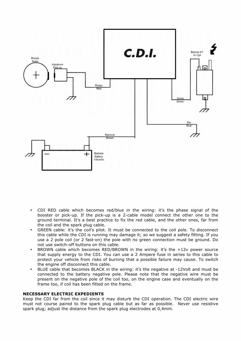
• CDI RED cable which becomes red/blue in the wiring: it’s the phase signal of the booster or pick-up. If the pick-up is a 2-cable model connect the other one to the ground terminal. It’s a best practice to fix the red cable, and the other ones, far from the coil and the spark plug cable.
• GREEN cable: it’s the coil’s pilot. It must be connected to the coil pole. To disconnect this cable while the CDI is running may damage it; so we suggest a safety fitting. If you use a 2 pole coil (or 2 fast-on) the pole with no green connection must be ground. Do not use switch-off buttons on this cable.
• BROWN cable which becomes RED/BROWN in the wiring: it’s the +12v power source that supply energy to the CDI. You can use a 2 Ampere fuse in series to this cable to protect your vehicle from risks of burning that a possible failure may cause. To switch the engine off disconnect this cable.
• BLUE cable that becomes BLACK in the wiring: it’s the negative at -12Volt and must be connected to the battery negative pole. Please note that the negative wire must be present on the negative pole of the coil too, on the engine case and eventually on the frame too, if coil has been fitted on the frame.
NECESSARY ELECTRIC EXPEDIENTS Keep the CDI far from the coil since it may disturb the CDI operation. The CDI electric wire must not course paired to the spark plug cable but as far as possible. Never use resistive spark plug; adjust the distance from the spark plug electrodes at 0,4mm.

MECHANICAL FITTING OF THE DEVICE The CDI must be fitted firmly to a part of the vehicle where there are no intensive vibrations or very high temperatures. OPERATING SYSTEM REQUIREMENTS FOR THE CDI PROGRAM “2013 POLINI programmer” has been conceived to be used with Window Microsoft® operating system starting from XP to Windows 7 and 8: we do not exclude the possibility to be used with other new operating systems, but at the moment it hasn’t been tested. The PC where you intend to install it must have the minimum requirements of P44, 512 Ram, CD-rom and DVD devices working, 200 MB available on the Hard disk, one free and working USB port. The best resolution for its correct display is 1024x768 but it works with superior resolution too. PC does not have any worm or other malware.

“2013 Programmer” software - Operating Manual Safety Improper regulations on the devices executed through “2013 Programmer” software may be dangerous and consequently endanger the physical integrity of people or damage engines and vehicles. Therefore these regulations should be implemented only by competent persons and only after careful evaluation of the potential risks that they entail. Therefore no responsibility for damages and accidents caused by incorrectly performed settings is assumed. Software use “2031 Programmer” is a program that permits to modify and customize the data setting. Copyright “2013 Programmer” is not a freeware program, it is not free of charge, and it is under anti-piracy laws’ in force. It is prohibited to copy and reproduce it if not authorized. Its use is only allowed together with a Polini device it is matched to. No responsibility will be assumed for malfunctioning, data lost, PC breakdown or to damages to the vehicle. Who uses it does it at his own risk and peril. It is forbidden to copy, even partially, this manual. OPERATING SYSTEM REQUIREMENTS FOR THE CDI PROGRAM “2013 POLINI programmer” has been conceived to be used with Window Microsoft® operating system starting from XP to Windows 7 and 8: we do not exclude the possibility to be used with other new operating systems, but at the moment it hasn’t been tested. The PC where you intend to install it must have the minimum requirements of P44, 512 Ram, CD-rom and DVD devices working, 200 MB available on the Hard disk, one free and working USB port. The best resolution for its correct display is 1024x768 but it works with superior resolution too. PC does not have any worm or other malware. Installation of the program cable Drive To use the programmer cable it is necessary to use the proper driver included in the file “Programmer Cable Driver” in the CD rom supplied. Important: do not insert the cable in the USB port before having installed its Driver. Once you have verified your PC operating system, open the “Application installer Driver” files. Software installation Use the original CD supplied and, after having inserted it in the DWD-CD Rom, launch the Set-up to start the installation and wait: if your PC includes “DotnetFx35” the installation will be fast, otherwise the operation will last some minutes more. When the installation is completed it is possible to launch the “Lektor 2012” software from the menu “Program” or “All programs” (it depends on the operating system) Main screen:
The main screen consists of a central graphic where on the horizontal axis there is the rpm range in multiple of 1000 RPM, and on the Vertical axis the ignition advance angle in multiple of 1 degree (°)

In the low side there is a series of buttons-functions, while on the top side there are a series of switches and indicators. Then there are some lines on the graphic, one yellow and a dotted light blue line. Lines or curves on the graphic Yellow line: it’s the line that indicates the advanced trend described by the Curve1. Dotted light blue line: it’s the line which indicates the value of the fixed advances, the FIX Confirmations and notifications in the top side of the graphic In the picture below the notifications and selections on the top size of the graphic are indicated.
Down buttons In the picture below the control buttons of the “2013 programmer” and following a short description of their functions
“+0.2°” o “-0.2°” buttons
By pressing these buttons you achieve an increase of the selected curve of 0,2 degrees with “+0.2” , or with a decrease of 2.2 degree with “10.2” button. Never exceed the FIX value or decrease under 0°. By pressing it several times you may achieve the variation you wish of the entire curve. “LOAD <-PC” button
By pressing this button you may take by the maps collection stored in the PC the wished one and put it on the graphic to display, modify or save it in the connected device. “Save ->PC” button
By pressing this button you may save in the maps collection saved in the PC the one you are displaying on the graphic, naming it properly. “Grid C1” button By pressing this button a grid appears with the value of the ignition curve trend related to the C1 curve. This grid will appear in the bottom part of the graphic in the left side (as in the photo below) and will disappear as soon as you will click on the graphic in another area. Its purpose is that to make a numerical analysis of the advance curve.
“Read Device” Button
It is the button that launches the reading process of the connected device: once the reading is completed the graphic will display the device contents.

In this regard please be careful to the correct sequence of the programming cable connection between CDI and PC: Insert the programming cable into the control unit. Insert the programming cable into the USB port of your PC. Press the "Read Device" button.
Now “2013 Programmer” will show a warning window that informs you that if you read a map the one already on the graphic will be erased:
By selecting “NO” you will return to the previous situation without reading the device; by pressing “YES” you will go on and the software will display the flashing notice:
If the device won’t be found a notice will appear saying that it is suggested to check and eventually to re-connect the device after 15 seconds from its disconnection; then it says that it will proceed off-line
On the contrary, if the device will be detected a notice will appear in the centre of the display :
And the program indicator placed on the right top side will show the reading evolution indicating the number of the delivered curve too.
Once the reading of the connected device is completed, on the graphic will appear the curve that adjusts the advance. Modify the curve as you like being careful not to exceed the maximum advance angle given by the fix angle. If you already have saved an advanced curve in your PC, upload it. “Write Device” button
It is the button that launches the writing process of the connected device: the mapping on the graphic is transferred. Once the writing is completed, the device will contain what previously appeared on the graphic. In this regard please be careful to the correct sequence of the programming cable connection between CDI and PC: WARNING: DO THIS OPERATION WITH NON-POWERED CONTROL UNIT
Insert the programming cable into the cdi Insert the programming cable into the USB port of your PC. Press the "Write Device" button
Now “2012 Lektor" will show warning windows; if the device is detected, it will also show the progress of the process in a manner similar to the reading process. Once the writing process is completed disconnect the programming cable and you can test the operation of the new set-tings on the engine. Important: in most cases, the device cannot be started with the programming cable connected!

“Exit” button
“Exit” button exits from the program and it returns to the operating system “Segment Input” button and section
It’s a group of buttons and boxes that contribute to one function only, to create a straight section of ignition advance curve, also very extensive, with just two points. The first point is given by "RPM 1" and "Angle 1", the second one from "Rpm2" and "Angle" 2. You can manually set the value in the boxes, or with a single click in the area where you want the point start. The dot indicates which point you set if you click on the graphic; in the example above, if you click the point 1 you be set so that of "Rpm1" and "Angle 1". So if you want to set a straight section like in the example:
Check that the dot is at point 1 (if it's not in step 1 just click on the point and it will place where you wish) Click the area on the graphic where you want to start the section (example 600 Rpm and 10 degrees), the dot will
move to point 1. Click the second point where you want to end the section (example 20000 Rpm and 20 degrees) the dot will rise to
step 1. Click the "Segment Input" Button, the curve will be equipped with the straight section selected.
You can get similar results by setting in the box the values manually; you need to make sure to set RPM1 bigger than RPM2.
CONFIRMATIONS: Name of the map read by the PC
It’s a space of 18 letters which represents the name of the map once it has been ridden by the PC and displayed on the graphic. Fix box
It’s the numerical representation of the Fix’s value. The Fix is the advance angle of the ignition system when the control unit that has been installed doesn’t make any correction. It’s the reference to the graphic and the ignition. To modify it, double click on the light blue figures, enter the value in the input window that appears and confirm. The graphic will automatically update to the new value. RPM Advance box
They are two boxes that only display the ignition advance angle and rpm in the exact point where you click. It’s for to know how many degrees at a certain point of a curve which is very complex or inclined. Direct the mouse to the point on the curve and after pressing with one click only two boxes will appear with the RPM and the angle at that range.

Creation of a new advance curve: Launch the software “2012 Lektor” and the screen below will appear.
The default situation that appears indicates that the FIX is at 28 Degree, the C1 curve is all at 26,4 degree. Considering that you have to modify the stretch from 7000 to 12000 Rpm in your engine, by operating with a reduction of about 11 degree you have to use the “Segment Input” function which is indicated below: click at 7000 rpm and 26.4° to set point 1 and at 12000Rpm and 16° to set point 2
After pressing “Segment input” button the C1 trend that will be displayed is the following:
Now connect the 12000-20000 stretch by selecting “Segment Input” function as follow:

In this situation you can save the map using the “Save->PC” button, make a copy of C1, modify the advance pressing ”+0.2°” or “-0.2°” button or change the value just double clicking on the graphic. Once the modification is completed you can send the map to the connected devices through “WriteDevice” button. “FIX” angle value survey The FIX angle is the ignition angle value that the system produces when the CDI does not make any modification “2013 PROGRAMMER” requires it to present the ignition curves with true value, even if all the system works with fictitious values too. To find the “FIX” value: *Insert in the “Fix” box 28 as hypothetic value *Set the ignition curve with a section where it is possible to work on the “Fix” value, which was 28°, as show in the picture above. *Gauge using a stroboscopic gun the ignition angle at 2500-3000 rpm: the value achieved is the “Fix” of our system. *Digit the new “Fix” value just achieved. If everything has been done in the right way, the angles on the graphic will be exactly as the ones executed by the connected device.