MINI TS - ribind.com · Alcuni punti della scheda elettrica sono sottoposti a tensioni pericolose....
32
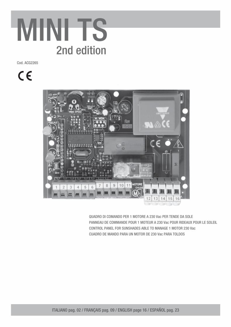
Cod. ACG2265 MINI TS 2nd edition QUADRO DI COMANDO PER 1 MOTORE A 230 Vac PER TENDE DA SOLE PANNEAU DE COMMANDE POUR 1 MOTEUR A 230 Vac POUR RIDEAUX POUR LE SOLEIL CONTROL PANEL FOR SUNSHADES ABLE TO MANAGE 1 MOTOR 230 Vac CUADRO DE MANDO PARA UN MOTOR DE 230 Vac PARA TOLDOS ITALIANO pag. 02 / FRANÇAIS pag. 09 / ENGLISH page 16 / ESPAÑOL pag. 23
Transcript of MINI TS - ribind.com · Alcuni punti della scheda elettrica sono sottoposti a tensioni pericolose....
Cod. ACG2265
MINI TS2nd edition
QUADRO DI COMANDO PER 1 MOTORE A 230 Vac PER TENDE DA SOLE
PANNEAU DE COMMANDE POUR 1 MOTEUR A 230 Vac POUR RIDEAUX POUR LE SOLEIL
CONTROL PANEL FOR SUNSHADES ABLE TO MANAGE 1 MOTOR 230 Vac
CUADRO DE MANDO PARA UN MOTOR DE 230 Vac PARA TOLDOS
ITALIANO pag. 02 / FRANÇAIS pag. 09 / ENGLISH page 16 / ESPAÑOL pag. 23
2
Il quadro di comando MINI TS è un’apparecchiatura universale adatta a gestire l’azionamento ed il controllo di tende da sole in modo semplice e completo. Questo prodotto comanda motori a 230V in corrente alternata fino a 500W (max) di potenza.
La logica della MINI TS offre la possibilità di gestire: - la rilevazione della velocità del vento- l’intensità della luce- la rilevazione della pioggiaconsentendo di aprire e/o chiudere la tenda da sole in modo completamente automatico in base alle condizioni metereologiche presenti.
ATTENZIONE: LEGGERE ATTENTAMENTE LE ISTRUZIONI PRIMA DI INSTALLARE IL QUADRO DI COMANDO!!!
INSTALLAZIONEAlcuni punti della scheda elettrica sono sottoposti a tensioni pericolose. L’installazione e la programmazione del quadro andrà pertanto svolta solamente da personale qualificato.Prevedere l’uso di un dispositivo di sicurezza che assicuri la sconnessione del quadro elettronico dall’alimentazione per effettuare manutenzioni.
Ciò può essere effettuato utilizzando per esempio un interruttore bipolare automatico manetotermico a norma, adeguato all’assorbimento di corrente del motore installato.Utilizzare cavi a norma per la parte di potenza, con una sezione adeguata all’assorbimento di corrente del motore installato.
CARATTERISTICHE TECNICHE MINI TS
Tensione di alimentazione 230 Vac +10% - 15%
Uscita motore 230 Vac 500W MAX cosϕ > 0,8
Assorbimento scheda 3W MAX (escluso accessori e utenze)
Tempo di lavoro motore 7 minuti
Tempo di attesa dopo allarme vento 7 minuti
Temperatura di funzionamento -10°C ÷ +60°C
Grado di Protezione IP54
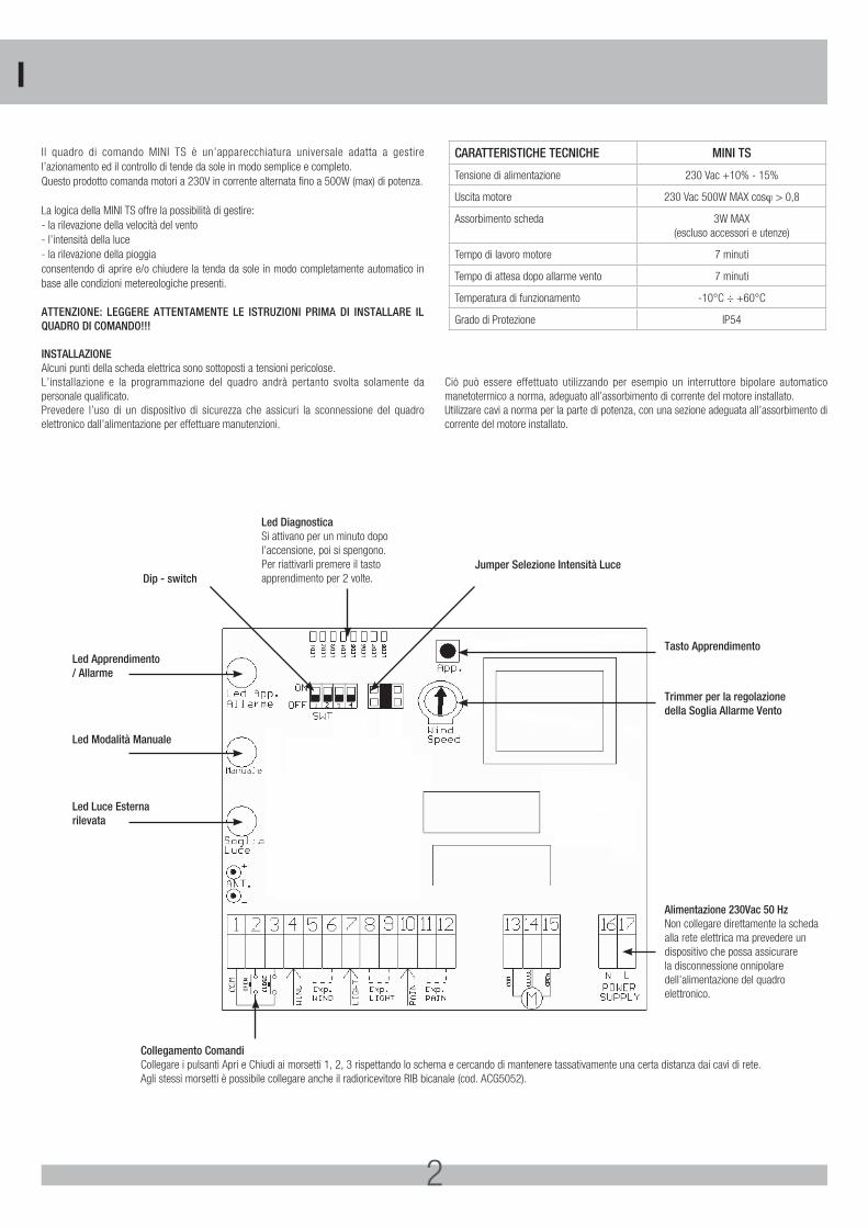
Led Diagnostica Si attivano per un minuto dopo l’accensione, poi si spengono. Per riattivarli premere il tasto apprendimento per 2 volte.
Collegamento ComandiCollegare i pulsanti Apri e Chiudi ai morsetti 1, 2, 3 rispettando lo schema e cercando di mantenere tassativamente una certa distanza dai cavi di rete. Agli stessi morsetti è possibile collegare anche il radioricevitore RIB bicanale (cod. ACG5052).
Led Apprendimento/ Allarme
Tasto Apprendimento
Trimmer per la regolazionedella Soglia Allarme Vento
Alimentazione 230Vac 50 HzNon collegare direttamente la scheda alla rete elettrica ma prevedere un dispositivo che possa assicurare la disconnessione onnipolare dell’alimentazione del quadro elettronico.
Dip - switchJumper Selezione Intensità Luce
Led Modalità Manuale
Led Luce Esternarilevata
I
3
Il quadro elettronico MINI TS è dotato di un pannello di controllo, con il quale è possibile monitorare il suo stato di funzionamento. Il pannello di controllo è composto da tre spie luminose (Led):- spia verde che segnala l’intensità della luce;- spia gialla che indica il funzionamento in modalità “posizionamento” ed “esclusione
sensori”;- spia rossa che segnala la condizione d’allarme.Con questi indicatori luminosi, si può verificare il corretto funzionamento del quadro elettronico ed individuare i possibili malfunzionamenti.Quando viene data tensione al quadro elettronico, tutti e tre i led indicatori rimarranno accesi per un secondo, dopo di che eseguiranno 3 lampeggi. Dopo alcuni secondi, se è presente il sensore d’intensità luminosa, il led verde comincerà a lampeggiare in modo differente a seconda dell’intensità di luce registrata.
Con questo led è infatti possibile effettuare la regolazione dell’intensità luminosa per l’apertura automatica della tenda. Nel caso in cui si presenti una condizione d’allarme (vento o pioggia), il led rosso comincerà a lampeggiare per tutto il periodo d’allarme (circa 7 min). Il led giallo segnala il funzionamento del dispositivo in modalità di posizionamento e esclusione sensori a seconda di come esso lampeggia.
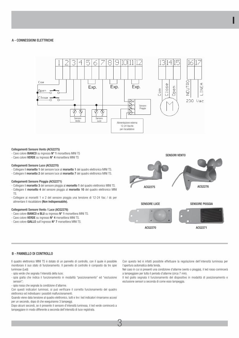
A - CONNESSIONI ELETTRICHE
B - PANNELLO DI CONTROLLO
SensoreVento
SensorePioggia
Alimentazione esterna12-24 Vac/dc
per riscaldatore
SensoreLuce
Collegamenti Sensore Vento (ACG2275)- Cavo colore BIANCO su ingresso N° 1 morsettiera MINI TS- Cavo colore VERDE su ingresso N° 4 morsettiera MINI TS
Collegamenti Sensore Luce (ACG2270)- Collegare il morsetto 1 del sensore luce al morsetto 1 del quadro elettronico MINI TS.- Collegare il morsetto 2 del sensore luce al morsetto 7 del quadro elettronico MINI TS.
Collegamenti Sensore Pioggia (ACG2271)- Collegare il morsetto 3 del sensore pioggia al morsetto 1 del quadro elettronico MINI TS.- Collegare il morsetto 4 del sensore pioggia al morsetto 10 del quadro elettronico MINI
TS.- Collegare ai morsetti 1 e 2 del sensore pioggia una tensione di 12-24 Vac / dc per
alimentare il riscaldatore (Non indispensabile).
Collegamenti Sensore Vento / Luce (ACG2276)- Cavo colore BIANCO e BLU su ingresso N° 1 morsettiera MINI TS.- Cavo colore VERDE su ingresso N° 4 morsettiera MINI TS.- Cavo colore GIALLO sull’ingresso N° 7 morsettiera MINI TS.
SENSORI VENTO
SENSORE LUCE
ACG2270
SENSORE PIOGGIA
ACG2271
ACG2275 ACG2276
I
4
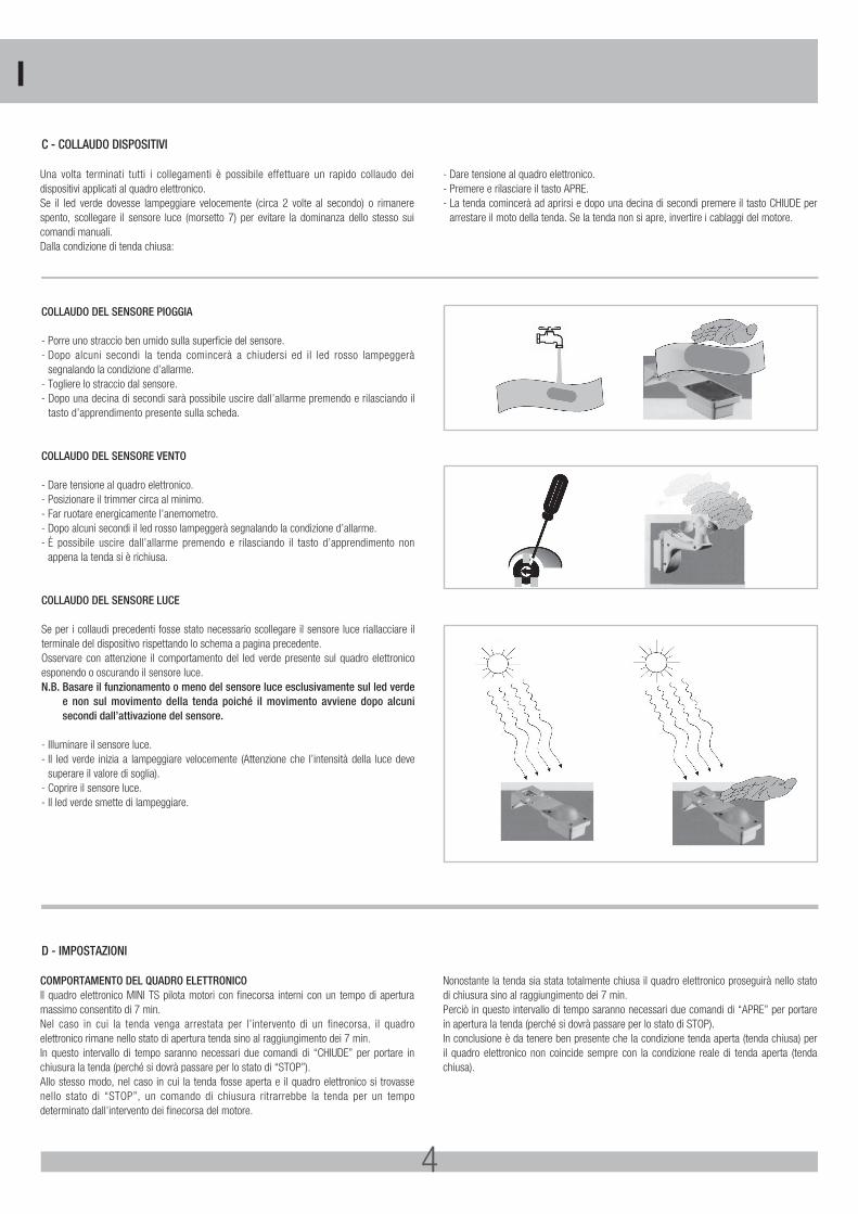
COLLAUDO DEL SENSORE PIOGGIA
- Porre uno straccio ben umido sulla superficie del sensore.- Dopo alcuni secondi la tenda comincerà a chiudersi ed il led rosso lampeggerà
segnalando la condizione d’allarme.- Togliere lo straccio dal sensore.- Dopo una decina di secondi sarà possibile uscire dall’allarme premendo e rilasciando il
tasto d’apprendimento presente sulla scheda.
COLLAUDO DEL SENSORE VENTO
- Dare tensione al quadro elettronico.- Posizionare il trimmer circa al minimo.- Far ruotare energicamente l’anemometro.- Dopo alcuni secondi il led rosso lampeggerà segnalando la condizione d’allarme.- È possibile uscire dall’allarme premendo e rilasciando il tasto d’apprendimento non
appena la tenda si è richiusa.
COLLAUDO DEL SENSORE LUCE
Se per i collaudi precedenti fosse stato necessario scollegare il sensore luce riallacciare il terminale del dispositivo rispettando lo schema a pagina precedente.Osservare con attenzione il comportamento del led verde presente sul quadro elettronico esponendo o oscurando il sensore luce.N.B. Basare il funzionamento o meno del sensore luce esclusivamente sul led verde
e non sul movimento della tenda poiché il movimento avviene dopo alcuni secondi dall’attivazione del sensore.
- Illuminare il sensore luce.- Il led verde inizia a lampeggiare velocemente (Attenzione che l’intensità della luce deve
superare il valore di soglia).- Coprire il sensore luce.- Il led verde smette di lampeggiare.
Una volta terminati tutti i collegamenti è possibile effettuare un rapido collaudo dei dispositivi applicati al quadro elettronico. Se il led verde dovesse lampeggiare velocemente (circa 2 volte al secondo) o rimanere spento, scollegare il sensore luce (morsetto 7) per evitare la dominanza dello stesso sui comandi manuali. Dalla condizione di tenda chiusa:
- Dare tensione al quadro elettronico.- Premere e rilasciare il tasto APRE.- La tenda comincerà ad aprirsi e dopo una decina di secondi premere il tasto CHIUDE per
arrestare il moto della tenda. Se la tenda non si apre, invertire i cablaggi del motore.
COMPORTAMENTO DEL QUADRO ELETTRONICOIl quadro elettronico MINI TS pilota motori con finecorsa interni con un tempo di apertura massimo consentito di 7 min. Nel caso in cui la tenda venga arrestata per l’intervento di un finecorsa, il quadro elettronico rimane nello stato di apertura tenda sino al raggiungimento dei 7 min. In questo intervallo di tempo saranno necessari due comandi di “CHIUDE” per portare in chiusura la tenda (perché si dovrà passare per lo stato di “STOP”).Allo stesso modo, nel caso in cui la tenda fosse aperta e il quadro elettronico si trovasse nello stato di “STOP”, un comando di chiusura ritrarrebbe la tenda per un tempo determinato dall’intervento dei finecorsa del motore.
Nonostante la tenda sia stata totalmente chiusa il quadro elettronico proseguirà nello stato di chiusura sino al raggiungimento dei 7 min. Perciò in questo intervallo di tempo saranno necessari due comandi di “APRE” per portare in apertura la tenda (perché si dovrà passare per lo stato di STOP). In conclusione è da tenere ben presente che la condizione tenda aperta (tenda chiusa) per il quadro elettronico non coincide sempre con la condizione reale di tenda aperta (tenda chiusa).
C - COLLAUDO DISPOSITIVI
D - IMPOSTAZIONI
I
5
SELEZIONE FUNZIONIImpostando il selettore di funzione (dip-switch) e il dispositivo di regolazione (trimmer) presenti nel quadro elettronico, sono possibili vari tipi di funzionamento. MINI TS viene distribuito con le seguenti impostazioni:- Soglia vento a 30 km/h.- Tempo apertura al massimo = 7 min.- Tempo chiusura al massimo = 7 min.- Tutti i dip in OFF (NOTA: al Dip 4 non sono associate funzioni).- Soglia luce 2 (intermedia).Applicando i vari dispositivi di controllo “ambientale” (anemometro, sensore d’intensità luminosa, sensore pioggia), si possono effettuare delle ulteriori regolazioni, alcune di queste agendo direttamente sulla scheda.
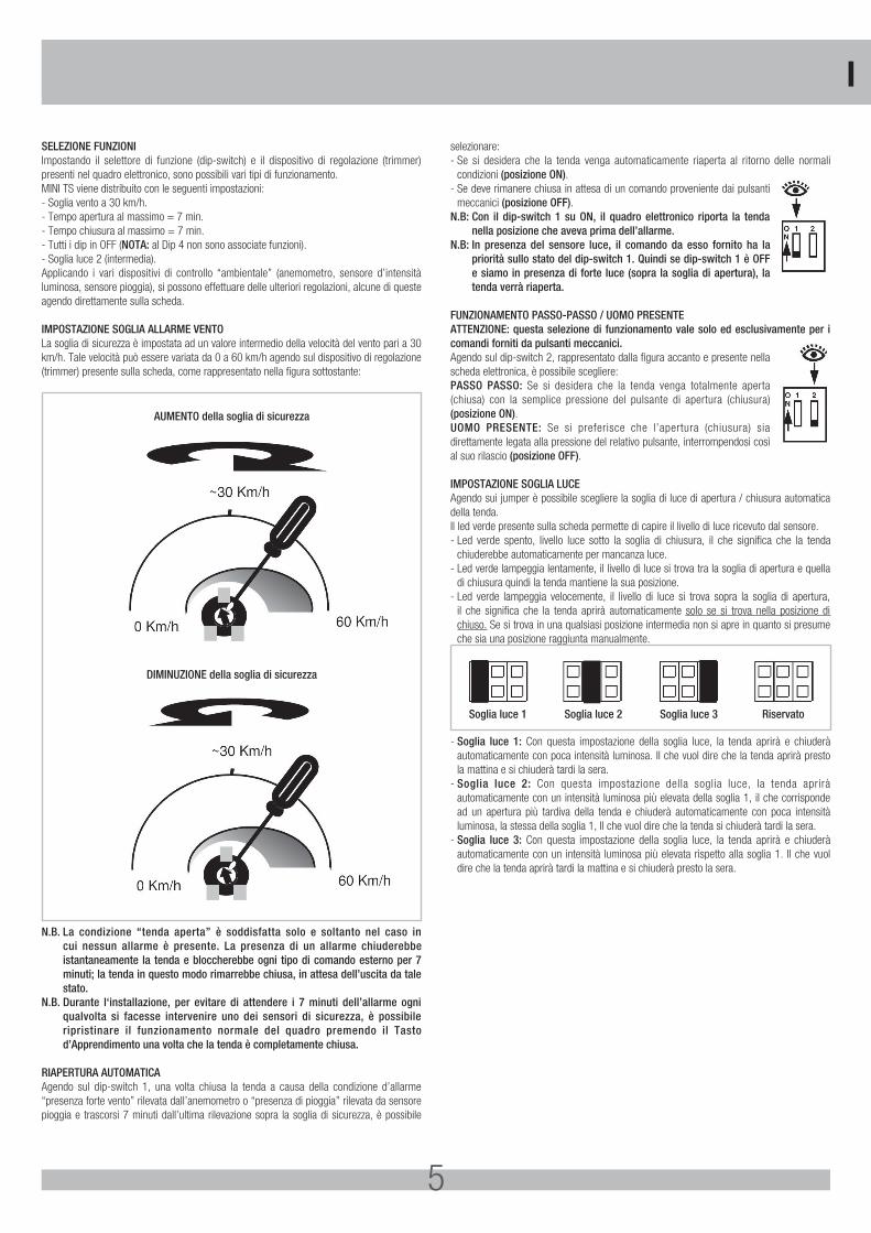
IMPOSTAZIONE SOGLIA ALLARME VENTOLa soglia di sicurezza è impostata ad un valore intermedio della velocità del vento pari a 30 km/h. Tale velocità può essere variata da 0 a 60 km/h agendo sul dispositivo di regolazione (trimmer) presente sulla scheda, come rappresentato nella figura sottostante:
AUMENTO della soglia di sicurezza
DIMINUZIONE della soglia di sicurezza
N.B. La condizione “tenda aperta” è soddisfatta solo e soltanto nel caso in cui nessun allarme è presente. La presenza di un allarme chiuderebbe istantaneamente la tenda e bloccherebbe ogni tipo di comando esterno per 7 minuti; la tenda in questo modo rimarrebbe chiusa, in attesa dell’uscita da tale stato.
N.B. Durante l‘installazione, per evitare di attendere i 7 minuti dell’allarme ogni qualvolta si facesse intervenire uno dei sensori di sicurezza, è possibile ripristinare il funzionamento normale del quadro premendo il Tasto d’Apprendimento una volta che la tenda è completamente chiusa.
RIAPERTURA AUTOMATICAAgendo sul dip-switch 1, una volta chiusa la tenda a causa della condizione d’allarme “presenza forte vento” rilevata dall’anemometro o “presenza di pioggia” rilevata da sensore pioggia e trascorsi 7 minuti dall’ultima rilevazione sopra la soglia di sicurezza, è possibile
selezionare:- Se si desidera che la tenda venga automaticamente riaperta al ritorno delle normali
condizioni (posizione ON).- Se deve rimanere chiusa in attesa di un comando proveniente dai pulsanti
meccanici (posizione OFF).N.B: Con il dip-switch 1 su ON, il quadro elettronico riporta la tenda
nella posizione che aveva prima dell’allarme.N.B: In presenza del sensore luce, il comando da esso fornito ha la
priorità sullo stato del dip-switch 1. Quindi se dip-switch 1 è OFF e siamo in presenza di forte luce (sopra la soglia di apertura), la tenda verrà riaperta.
FUNZIONAMENTO PASSO-PASSO / UOMO PRESENTEATTENZIONE: questa selezione di funzionamento vale solo ed esclusivamente per i comandi forniti da pulsanti meccanici.Agendo sul dip-switch 2, rappresentato dalla figura accanto e presente nella scheda elettronica, è possibile scegliere:PASSO PASSO: Se si desidera che la tenda venga totalmente aperta (chiusa) con la semplice pressione del pulsante di apertura (chiusura)(posizione ON).UOMO PRESENTE: Se si preferisce che l’apertura (chiusura) sia direttamente legata alla pressione del relativo pulsante, interrompendosi così al suo rilascio (posizione OFF).
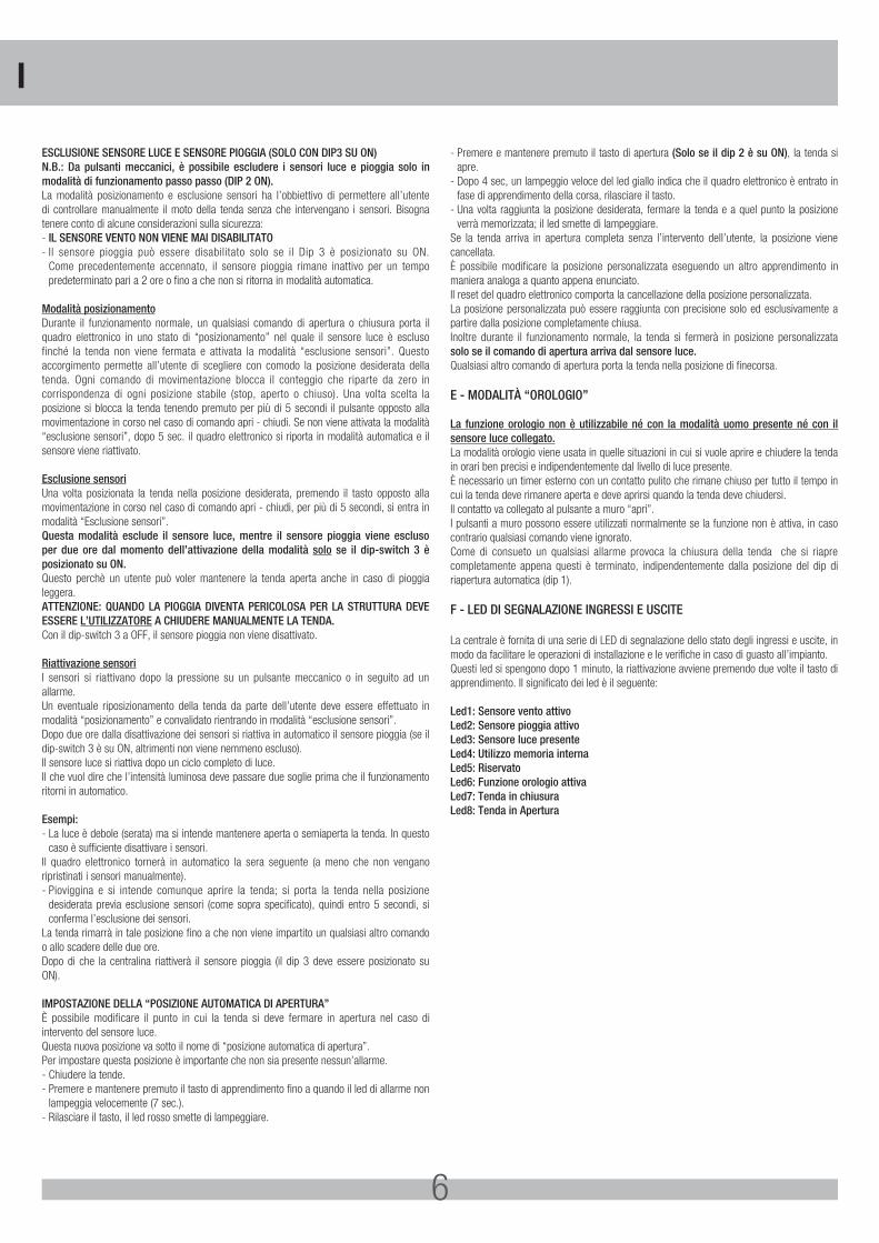
IMPOSTAZIONE SOGLIA LUCEAgendo sui jumper è possibile scegliere la soglia di luce di apertura / chiusura automatica della tenda. Il led verde presente sulla scheda permette di capire il livello di luce ricevuto dal sensore. - Led verde spento, livello luce sotto la soglia di chiusura, il che significa che la tenda
chiuderebbe automaticamente per mancanza luce. - Led verde lampeggia lentamente, il livello di luce si trova tra la soglia di apertura e quella
di chiusura quindi la tenda mantiene la sua posizione. - Led verde lampeggia velocemente, il livello di luce si trova sopra la soglia di apertura,
il che significa che la tenda aprirà automaticamente solo se si trova nella posizione di chiuso. Se si trova in una qualsiasi posizione intermedia non si apre in quanto si presume che sia una posizione raggiunta manualmente.
Soglia luce 1 Soglia luce 2 Soglia luce 3 Riservato
- Soglia luce 1: Con questa impostazione della soglia luce, la tenda aprirà e chiuderà automaticamente con poca intensità luminosa. Il che vuol dire che la tenda aprirà presto la mattina e si chiuderà tardi la sera.
- Soglia luce 2: Con questa impostazione della soglia luce, la tenda aprirà automaticamente con un intensità luminosa più elevata della soglia 1, il che corrisponde ad un apertura più tardiva della tenda e chiuderà automaticamente con poca intensità luminosa, la stessa della soglia 1, Il che vuol dire che la tenda si chiuderà tardi la sera.
- Soglia luce 3: Con questa impostazione della soglia luce, la tenda aprirà e chiuderà automaticamente con un intensità luminosa più elevata rispetto alla soglia 1. Il che vuol dire che la tenda aprirà tardi la mattina e si chiuderà presto la sera.
I
6
ESCLUSIONE SENSORE LUCE E SENSORE PIOGGIA (SOLO CON DIP3 SU ON)N.B.: Da pulsanti meccanici, è possibile escludere i sensori luce e pioggia solo in modalità di funzionamento passo passo (DIP 2 ON).La modalità posizionamento e esclusione sensori ha l’obbiettivo di permettere all’utente di controllare manualmente il moto della tenda senza che intervengano i sensori. Bisogna tenere conto di alcune considerazioni sulla sicurezza:- IL SENSORE VENTO NON VIENE MAI DISABILITATO- Il sensore pioggia può essere disabilitato solo se il Dip 3 è posizionato su ON.
Come precedentemente accennato, il sensore pioggia rimane inattivo per un tempo predeterminato pari a 2 ore o fino a che non si ritorna in modalità automatica.
Modalità posizionamentoDurante il funzionamento normale, un qualsiasi comando di apertura o chiusura porta il quadro elettronico in uno stato di “posizionamento” nel quale il sensore luce è escluso finché la tenda non viene fermata e attivata la modalità “esclusione sensori”. Questo accorgimento permette all’utente di scegliere con comodo la posizione desiderata della tenda. Ogni comando di movimentazione blocca il conteggio che riparte da zero in corrispondenza di ogni posizione stabile (stop, aperto o chiuso). Una volta scelta la posizione si blocca la tenda tenendo premuto per più di 5 secondi il pulsante opposto alla movimentazione in corso nel caso di comando apri - chiudi. Se non viene attivata la modalità “esclusione sensori”, dopo 5 sec. il quadro elettronico si riporta in modalità automatica e il sensore viene riattivato.
Esclusione sensoriUna volta posizionata la tenda nella posizione desiderata, premendo il tasto opposto alla movimentazione in corso nel caso di comando apri - chiudi, per più di 5 secondi, si entra in modalità “Esclusione sensori”.Questa modalità esclude il sensore luce, mentre il sensore pioggia viene escluso per due ore dal momento dell’attivazione della modalità solo se il dip-switch 3 è posizionato su ON.Questo perchè un utente può voler mantenere la tenda aperta anche in caso di pioggia leggera.ATTENZIONE: QUANDO LA PIOGGIA DIVENTA PERICOLOSA PER LA STRUTTURA DEVE ESSERE L’UTILIZZATORE A CHIUDERE MANUALMENTE LA TENDA.Con il dip-switch 3 a OFF, il sensore pioggia non viene disattivato.
Riattivazione sensoriI sensori si riattivano dopo la pressione su un pulsante meccanico o in seguito ad un allarme. Un eventuale riposizionamento della tenda da parte dell’utente deve essere effettuato in modalità “posizionamento” e convalidato rientrando in modalità “esclusione sensori”.Dopo due ore dalla disattivazione dei sensori si riattiva in automatico il sensore pioggia (se il dip-switch 3 è su ON, altrimenti non viene nemmeno escluso).Il sensore luce si riattiva dopo un ciclo completo di luce. Il che vuol dire che l’intensità luminosa deve passare due soglie prima che il funzionamento ritorni in automatico.
Esempi:- La luce è debole (serata) ma si intende mantenere aperta o semiaperta la tenda. In questo
caso è sufficiente disattivare i sensori. Il quadro elettronico tornerà in automatico la sera seguente (a meno che non vengano ripristinati i sensori manualmente).- Pioviggina e si intende comunque aprire la tenda; si porta la tenda nella posizione
desiderata previa esclusione sensori (come sopra specificato), quindi entro 5 secondi, si conferma l’esclusione dei sensori.
La tenda rimarrà in tale posizione fino a che non viene impartito un qualsiasi altro comando o allo scadere delle due ore. Dopo di che la centralina riattiverà il sensore pioggia (il dip 3 deve essere posizionato su ON).
IMPOSTAZIONE DELLA “POSIZIONE AUTOMATICA DI APERTURA”È possibile modificare il punto in cui la tenda si deve fermare in apertura nel caso di intervento del sensore luce. Questa nuova posizione va sotto il nome di “posizione automatica di apertura”. Per impostare questa posizione è importante che non sia presente nessun’allarme.- Chiudere la tende.- Premere e mantenere premuto il tasto di apprendimento fino a quando il led di allarme non
lampeggia velocemente (7 sec.).- Rilasciare il tasto, il led rosso smette di lampeggiare.
- Premere e mantenere premuto il tasto di apertura (Solo se il dip 2 è su ON), la tenda si apre.
- Dopo 4 sec, un lampeggio veloce del led giallo indica che il quadro elettronico è entrato in fase di apprendimento della corsa, rilasciare il tasto.
- Una volta raggiunta la posizione desiderata, fermare la tenda e a quel punto la posizione verrà memorizzata; il led smette di lampeggiare.
Se la tenda arriva in apertura completa senza l’intervento dell’utente, la posizione viene cancellata. È possibile modificare la posizione personalizzata eseguendo un altro apprendimento in maniera analoga a quanto appena enunciato.Il reset del quadro elettronico comporta la cancellazione della posizione personalizzata.La posizione personalizzata può essere raggiunta con precisione solo ed esclusivamente a partire dalla posizione completamente chiusa. Inoltre durante il funzionamento normale, la tenda si fermerà in posizione personalizzata solo se il comando di apertura arriva dal sensore luce. Qualsiasi altro comando di apertura porta la tenda nella posizione di finecorsa.
E - MODALITÀ “OROLOGIO”
La funzione orologio non è utilizzabile né con la modalità uomo presente né con il sensore luce collegato.La modalità orologio viene usata in quelle situazioni in cui si vuole aprire e chiudere la tenda in orari ben precisi e indipendentemente dal livello di luce presente. È necessario un timer esterno con un contatto pulito che rimane chiuso per tutto il tempo in cui la tenda deve rimanere aperta e deve aprirsi quando la tenda deve chiudersi.Il contatto va collegato al pulsante a muro “apri”. I pulsanti a muro possono essere utilizzati normalmente se la funzione non è attiva, in caso contrario qualsiasi comando viene ignorato.Come di consueto un qualsiasi allarme provoca la chiusura della tenda che si riapre completamente appena questi è terminato, indipendentemente dalla posizione del dip di riapertura automatica (dip 1).
F - LED DI SEGNALAZIONE INGRESSI E USCITE
La centrale è fornita di una serie di LED di segnalazione dello stato degli ingressi e uscite, in modo da facilitare le operazioni di installazione e le verifiche in caso di guasto all’impianto. Questi led si spengono dopo 1 minuto, la riattivazione avviene premendo due volte il tasto di apprendimento. Il significato dei led è il seguente:
Led1: Sensore vento attivoLed2: Sensore pioggia attivoLed3: Sensore luce presenteLed4: Utilizzo memoria internaLed5: RiservatoLed6: Funzione orologio attivaLed7: Tenda in chiusuraLed8: Tenda in Apertura
I
7
G - MODALITÀ “INVERNO”
La modalità “inverno” permette di escludere l’apertura automatica della tenda. Per attivare questa modalità è necessario chiudere la tenda e una volta chiusa, premere per 3 secondi il tasto stop. L’entrata in tale modalità è data dal lampeggio lento (un lampeggio ogni 3 secondi). La pressione del tasto APRI da pulsante a muro ripristina il normale funzionamento del quadro elettronico.
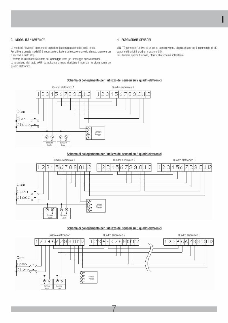
H - ESPANSIONE SENSORI
MINI TS permette l’utilizzo di un unico sensore vento, pioggia e luce per il commando di più quadri elettronici fino ad un massimo di 5. Per utilizzare questa funzione, riferirsi allo schema sottostante.
SensoreVento
SensorePioggia
SensoreLuce
Quadro elettronico 1 Quadro elettronico 2
SensoreVento
SensorePioggia
SensoreLuce
Quadro elettronico 1 Quadro elettronico 2 Quadro elettronico 3
SensoreVento
SensorePioggia
SensoreLuce
Quadro elettronico 1 Quadro elettronico 2 Quadro elettronico 5
Schema di collegamento per l’utilizzo dei sensori su 2 quadri elettronici
Schema di collegamento per l’utilizzo dei sensori su 3 quadri elettronici
Schema di collegamento per l’utilizzo dei sensori su 5 quadri elettronici
I
8
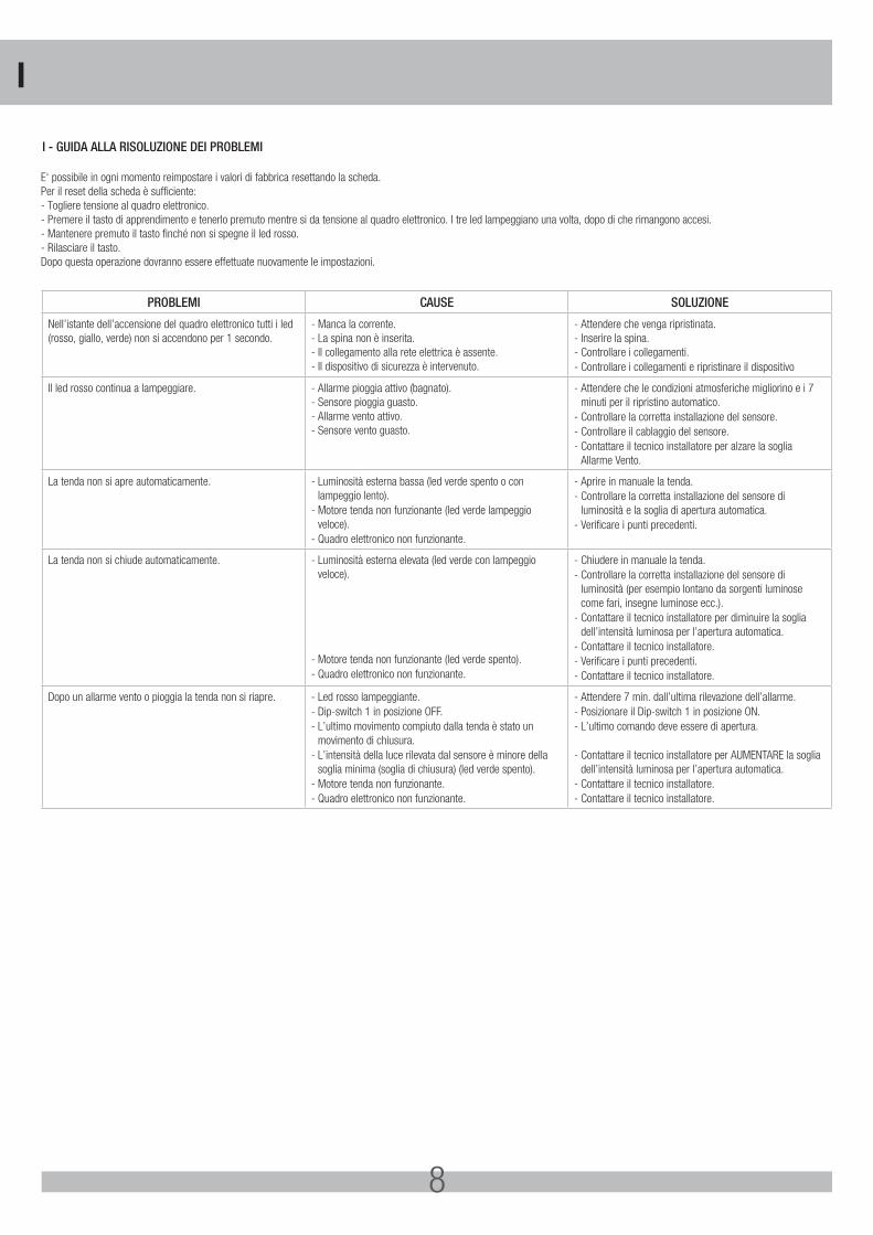
E‘ possibile in ogni momento reimpostare i valori di fabbrica resettando la scheda. Per il reset della scheda è sufficiente:- Togliere tensione al quadro elettronico.- Premere il tasto di apprendimento e tenerlo premuto mentre si da tensione al quadro elettronico. I tre led lampeggiano una volta, dopo di che rimangono accesi.- Mantenere premuto il tasto finché non si spegne il led rosso.- Rilasciare il tasto. Dopo questa operazione dovranno essere effettuate nuovamente le impostazioni.
PROBLEMI CAUSE SOLUZIONE
Nell’istante dell’accensione del quadro elettronico tutti i led (rosso, giallo, verde) non si accendono per 1 secondo.
- Manca la corrente.- La spina non è inserita.- Il collegamento alla rete elettrica è assente.- Il dispositivo di sicurezza è intervenuto.
- Attendere che venga ripristinata.- Inserire la spina.- Controllare i collegamenti.- Controllare i collegamenti e ripristinare il dispositivo
Il led rosso continua a lampeggiare. - Allarme pioggia attivo (bagnato).- Sensore pioggia guasto.- Allarme vento attivo.- Sensore vento guasto.
- Attendere che le condizioni atmosferiche migliorino e i 7 minuti per il ripristino automatico.
- Controllare la corretta installazione del sensore.- Controllare il cablaggio del sensore.- Contattare il tecnico installatore per alzare la soglia
Allarme Vento.
La tenda non si apre automaticamente. - Luminosità esterna bassa (led verde spento o con lampeggio lento).
- Motore tenda non funzionante (led verde lampeggio veloce).
- Quadro elettronico non funzionante.
- Aprire in manuale la tenda.- Controllare la corretta installazione del sensore di
luminosità e la soglia di apertura automatica.- Verificare i punti precedenti.
La tenda non si chiude automaticamente. - Luminosità esterna elevata (led verde con lampeggio veloce).
- Motore tenda non funzionante (led verde spento).- Quadro elettronico non funzionante.
- Chiudere in manuale la tenda.- Controllare la corretta installazione del sensore di
luminosità (per esempio lontano da sorgenti luminose come fari, insegne luminose ecc.).
- Contattare il tecnico installatore per diminuire la soglia dell’intensità luminosa per l’apertura automatica.
- Contattare il tecnico installatore.- Verificare i punti precedenti.- Contattare il tecnico installatore.
Dopo un allarme vento o pioggia la tenda non si riapre. - Led rosso lampeggiante.- Dip-switch 1 in posizione OFF.- L’ultimo movimento compiuto dalla tenda è stato un
movimento di chiusura.- L’intensità della luce rilevata dal sensore è minore della
soglia minima (soglia di chiusura) (led verde spento).- Motore tenda non funzionante.- Quadro elettronico non funzionante.
- Attendere 7 min. dall’ultima rilevazione dell’allarme.- Posizionare il Dip-switch 1 in posizione ON.- L’ultimo comando deve essere di apertura.
- Contattare il tecnico installatore per AUMENTARE la soglia dell’intensità luminosa per l’apertura automatica.
- Contattare il tecnico installatore.- Contattare il tecnico installatore.
I - GUIDA ALLA RISOLUZIONE DEI PROBLEMI
I
9
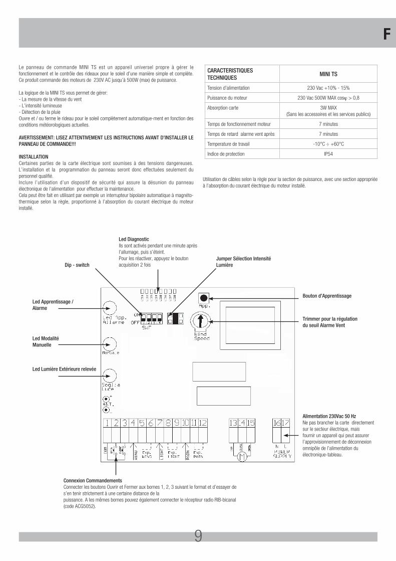
Le panneau de commande MINI TS est un appareil universel propre à gérer le fonctionnement et le contrôle des rideaux pour le soleil d’une manière simple et complète. Ce produit commande des moteurs de 230V AC jusqu’à 500W (max) de puissance.
La logique de la MINI TS vous permet de gérer:- La mesure de la vitesse du vent- L’intensité lumineuse- Détection de la pluieOuvre et / ou ferme le rideau pour le soleil complètement automatique-ment en fonction des conditions météorologiques actuelles.
AVERTISSEMENT: LISEZ ATTENTIVEMENT LES INSTRUCTIONS AVANT D’INSTALLER LE PANNEAU DE COMMANDE!!!
INSTALLATION Certaines parties de la carte électrique sont soumises à des tensions dangereuses. L’installation et la programmation du panneau seront donc effectuées seulement du personnel qualifié.Inclure l’utilisation d’un dispositif de sécurité qui assure la désunion du panneau électronique de l’alimentation pour effectuer la maintenance.Cela peut être fait en utilisant par exemple un interrupteur bipolaire automatique à magnéto-thermique selon la règle, proportionné à l’absorption du courant électrique du moteur installé.
Utilisation de câbles selon la règle pour la section de puissance, avec une section appropriée à l’absorption du courant électrique du moteur installé.
CARACTERISTIQUESTECHNIQUES
MINI TS
Tension d’alimentation 230 Vac +10% - 15%
Puissance du moteur 230 Vac 500W MAX cosϕ > 0,8
Absorption carte 3W MAX (Sans les accessoires et les services publics)
Temps de fonctionnement moteur 7 minutes
Temps de retard alarme vent après 7 minutes
Temperature de travail -10°C ÷ +60°C
Indìce de protection IP54
Led DiagnosticIls sont activés pendant une minute après l’allumage, puis s’éteint. Pour les réactiver, appuyez le bouton acquisition 2 fois
Connexion Commandements Connecter les boutons Ouvrir et Fermer aux bornes 1, 2, 3 suivant le format et d’essayer de s’en tenir strictement à une certaine distance de lapuissance. A les mêmes bornes pouvez également connecter le récepteur radio RIB-bicanal (code ACG5052).
Led Apprentissage /Alarme
Bouton d’Apprentissage
Trimmer pour la régulationdu seuil Alarme Vent
Alimentation 230Vac 50 Hz Ne pas brancher la carte directement sur le secteur électrique, mais fournir un appareil qui peut assurer l’approvisionnement de déconnexion omnipôle de l’alimentation du électronique-tableau.
Dip - switchJumper Sélection Intensité Lumière
Led ModalitéManuelle
Led Lumière Extérieure relevée
F
10
La centrale MINI TS est doté d’un panneau de contrôle avec lequel il est possible contrôler son état de fonctionnement. Le panneau de contrôle est composé de trois voyants (Led):- voyant vert signale l’intensité de la lumière;- voyant jaune indique le fonctionnement en modalité “positionnement” et “exclusion
capteurs”;- voyant rouge signale la condition d’alarme.Avec ces indicateurs lumineux, on peut vérifier le fonctionnement correct de la centrale et déterminer les mauvais fonctionnements possibles.Quand on donne tension à la centrale, tous les trois led indicateurs resteront allumé pour une seconde, après quoi ils exécuteront 3 clignotements. Après quelques second, s’il est présent le capteur d’intensité lumineuse, le led vert commencera à clignoter de manière différente selon l’intensité de lumière reçue.
Avec ce led il est en effet possible d’effectuer la régulation de l’intensité lumineuse pour l’ouverture automatique du store. Dans le cas ou il se présente une condition d’alarme, vent ou pluie, le led rouge il commencera à clignoter pour toute la période d’alarme, environ 7 min.Le led jaune signale le fonctionnement du dispositif en modalité de positionnement et exclusion.
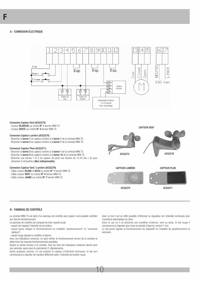
A - CONNEXION ÉLECTRIQUE
B - PANNEAU DE CONTRÔLE
Capteur devent
Capteurde pluie
Alimentation Externe12-24 Vac/dc
Pour réchauffage
Capteur delumière
Connexion Capteur Vent (ACG2275)- Couleur BLANCHE sur entrée N° 1 bornier MINI TS- Couleur VERTE sur entrée N° 4 bornier MINI TS
Connexion Capteur Lumière (ACG2270)- Brancher la borne 1 du capteur lumière à la borne 1 de la centrale MINI TS.- Brancher la borne 2 du capteur lumière à la borne 7 de la centrale MINI TS.
Connexion Capteur Pluie (ACG2271)- Brancher la borne 3 du capteur lumière à la borne 1 de la centrale MINI TS.- Brancher la borne 4 du capteur lumière à la borne 10 de la centrale MINI TS.- Brancher aux bornes 1 et 2 du capteur de pluie une tension de 12-24 Vac / dc pour
alimenter le réchauffeur (Non indispensable)
Connexion Capteur Vent / Lumière (ACG2276)- Câble couleur BLANC et BLEU su entrée N° 1 bornier MINI TS.- Câble couleur VERT sur entrée N° 4 bornier MINI TS.- Câble couleur JAUNE sur entrée N° 7 bornier MINI TS.
CAPTEUR VENT
CAPTEUR LUMIÈRE
ACG2270
CAPTEUR PLUIE
ACG2271
ACG2275 ACG2276
F
11
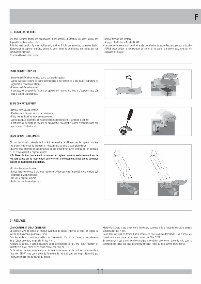
ESSAI DU CAPTEUR PLUIE
- Mettre un chiffon bien humide sur la surface du capteur.- Après quelques second le store commencera à se fermer et le led rouge clignotera en
signalant la condition d’alarme.- Enlever le chiffon du capteur.- Il est possible de sortir de l’alarme en appuyant et relâchant la touche d’apprentissage dès
que le store s’est refermée.
ESSAI DU CAPTEUR VENT
- Donner tension à la centrale.- Positionner le trimmer environ au minimum.- Faire tourner l’anémomètre énergiquement.- Après quelques second le led rouge clignotera en signalant la condition d’alarme.- Il est possible de sortir de l’alarme en appuyant et relâchant la touche d’apprentissage dès
que le store s’est refermée.
ESSAI DU CAPTEUR LUMIÈRE
Si pour les essais précédents il à été nécessaire de débrancher le capteur lumière rebrancher le terminal du dispositif en respectant le schéma à page précédente.Observer avec attention le comportement du led présent vert sur la centrale qui en exposant ou en obscurcissant le capteur lumière.N.B. Baser le fonctionnement ou moins du capteur lumière exclusivement sur le led vert et pas sur le mouvement du store car le mouvement arrive après quelques second de l’activation du capteur.
- Éclairer le capteur lumière.- Le led vert commence à clignoter rapidement (Attention que l’intensité, de la lumière doit
dépasser la valeur de seuil.)- Couvrir le capteur lumière.- Le led vert arrête de clignoter.
Une fois terminée toutes les connexions, il est possible d’effectuer un essai rapide des dispositifs appliqué à la centrale. Si le led vert devait clignoter rapidement, environ 2 fois par seconde, ou rester éteint, débrancher le capteur lumière, borne 7, pour éviter la dominance du même sur les commandes manuels. De la condition de store fermé:
- Donner tension à la centrale.- Appuyer et relâcher la touche OUVRE.- Le store commencera à s’ouvrir et après une dizaine de secondes, appuyer sur la touche
FERME pour arrêter le mouvement du store. Si le store ne s’ouvre pas, inverser les câblages du moteur.
COMPORTEMENT DE LA CENTRALELa centrale MINI TS pilote un moteur avec fins de course internes et avec un temps de maximum d’ouverture permis de 7 min. Dans le cas dans ou le store s’arrête pour l’intervention d’un fin de course, la centrale reste dans l’état d’ouverture jusqu’a la fin des 7 min. Pendant ce temps, il sera nécessaire deux commandes de “FERME” pour reporter en fermeture le store, parce qu’on devra passer par l’état de STOP.De la même manière, dans le cas ou le store a été ouvert et la centrale se trouve dans l’état de “STOP”, une commande de fermeture la retirerait pour un temps déterminé par l’intervention des fins de course du moteur.
Malgré le fait que le store soit fermé la centrale continuera dans l’état de fermeture jusqu’à la réalisation des 7 min. Donc dans cet laps de temps il sera nécessaire deux commandes”OUVRE” pour porter en ouverture le store, parce qu’on devra passer par l’état STOP. En conclusion il est à tenir bien présent que la condition store ouvert (store fermé), pour la centrale ne coïncide pas toujours avec la condition réelle de store ouvert (store fermé).
C - ESSAI DISPOSITIFS
D - RÉGLAGES
F
12
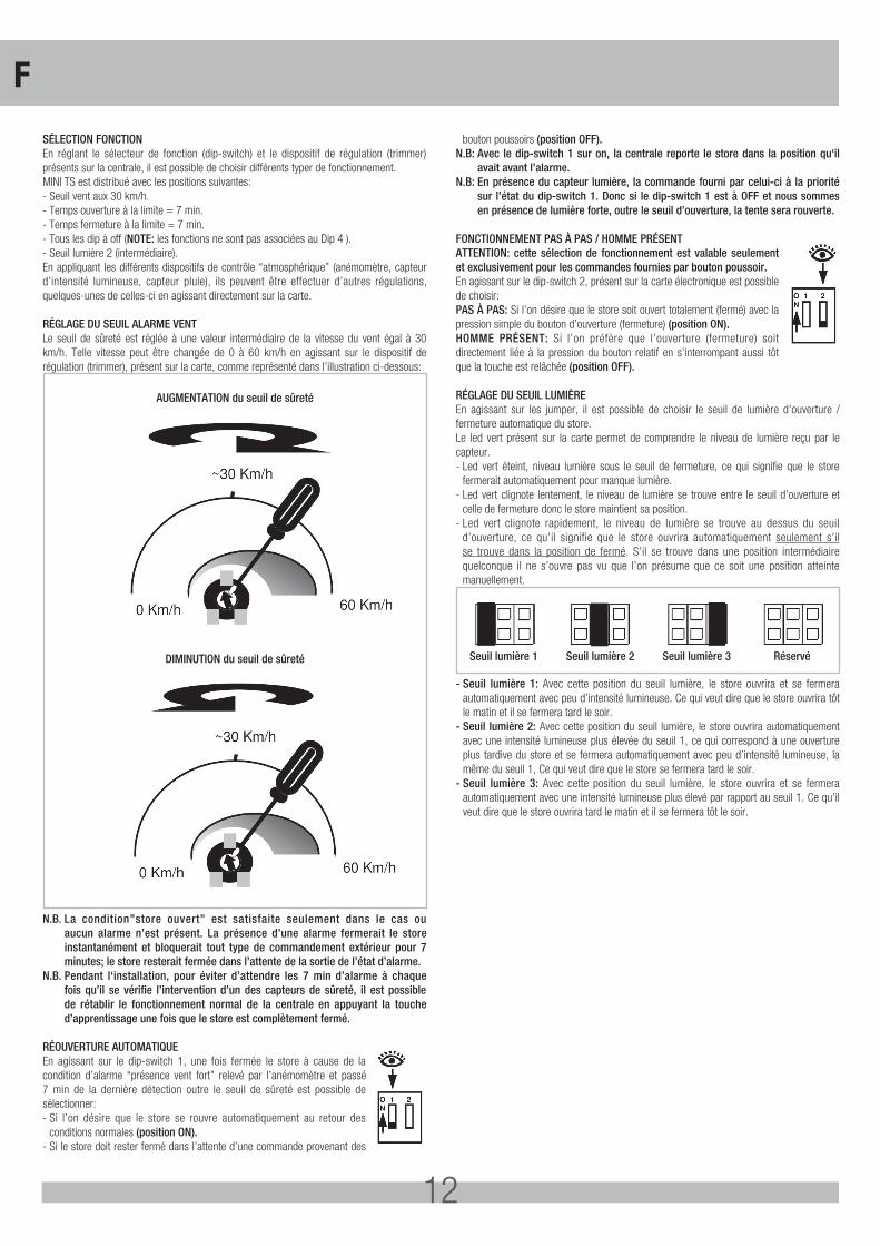
SÉLECTION FONCTIONEn réglant le sélecteur de fonction (dip-switch) et le dispositif de régulation (trimmer) présents sur la centrale, il est possible de choisir différents typer de fonctionnement. MINI TS est distribué avec les positions suivantes:- Seuil vent aux 30 km/h.- Temps ouverture à la limite = 7 min.- Temps fermeture à la limite = 7 min.- Tous les dip à off (NOTE: les fonctions ne sont pas associées au Dip 4 ).- Seuil lumière 2 (intermédiaire).En appliquant les différents dispositifs de contrôle “atmosphérique” (anémomètre, capteur d’intensité lumineuse, capteur pluie), ils peuvent être effectuer d’autres régulations, quelques-unes de celles-ci en agissant directement sur la carte.
RÉGLAGE DU SEUIL ALARME VENTLe seuil de sûreté est réglée à une valeur intermédiaire de la vitesse du vent égal à 30 km/h. Telle vitesse peut être changée de 0 à 60 km/h en agissant sur le dispositif de régulation (trimmer), présent sur la carte, comme représenté dans l’illustration ci-dessous:
AUGMENTATION du seuil de sûreté
DIMINUTION du seuil de sûreté
N.B. La condition”store ouvert” est satisfaite seulement dans le cas ou aucun alarme n’est présent. La présence d’une alarme fermerait le store instantanément et bloquerait tout type de commandement extérieur pour 7 minutes; le store resterait fermée dans l’attente de la sortie de l’état d’alarme.
N.B. Pendant l‘installation, pour éviter d’attendre les 7 min d’alarme à chaque fois qu’il se vérifie l’intervention d’un des capteurs de sûreté, il est possible de rétablir le fonctionnement normal de la centrale en appuyant la touche d’apprentissage une fois que le store est complètement fermé.
RÉOUVERTURE AUTOMATIQUEEn agissant sur le dip-switch 1, une fois fermée le store à cause de la condition d’alarme “présence vent fort” relevé par l’anémomètre et passé 7 min de la dernière détection outre le seuil de sûreté est possible de sélectionner:- Si l’on désire que le store se rouvre automatiquement au retour des
conditions normales (position ON).- Si le store doit rester fermé dans l’attente d’une commande provenant des
bouton poussoirs (position OFF).N.B: Avec le dip-switch 1 sur on, la centrale reporte le store dans la position qu‘il
avait avant l’alarme.N.B: En présence du capteur lumière, la commande fourni par celui-ci à la priorité
sur l’état du dip-switch 1. Donc si le dip-switch 1 est à OFF et nous sommes en présence de lumière forte, outre le seuil d’ouverture, la tente sera rouverte.
FONCTIONNEMENT PAS À PAS / HOMME PRÉSENTATTENTION: cette sélection de fonctionnement est valable seulement et exclusivement pour les commandes fournies par bouton poussoir.En agissant sur le dip-switch 2, présent sur la carte électronique est possible de choisir:PAS À PAS: Si l’on désire que le store soit ouvert totalement (fermé) avec la pression simple du bouton d’ouverture (fermeture) (position ON).HOMME PRÉSENT: Si l’on préfère que l’ouverture (fermeture) soit directement liée à la pression du bouton relatif en s’interrompant aussi tôt que la touche est relâchée (position OFF).
RÉGLAGE DU SEUIL LUMIÈREEn agissant sur les jumper, il est possible de choisir le seuil de lumière d’ouverture / fermeture automatique du store. Le led vert présent sur la carte permet de comprendre le niveau de lumière reçu par le capteur. - Led vert éteint, niveau lumière sous le seuil de fermeture, ce qui signifie que le store
fermerait automatiquement pour manque lumière. - Led vert clignote lentement, le niveau de lumière se trouve entre le seuil d’ouverture et
celle de fermeture donc le store maintient sa position. - Led vert clignote rapidement, le niveau de lumière se trouve au dessus du seuil
d’ouverture, ce qu’il signifie que le store ouvrira automatiquement seulement s’il se trouve dans la position de fermé. S’il se trouve dans une position intermédiaire quelconque il ne s’ouvre pas vu que l’on présume que ce soit une position atteinte manuellement.
Seuil lumière 1 Seuil lumière 2 Seuil lumière 3 Réservé
- Seuil lumière 1: Avec cette position du seuil lumière, le store ouvrira et se fermera automatiquement avec peu d’intensité lumineuse. Ce qui veut dire que le store ouvrira tôt le matin et il se fermera tard le soir.
- Seuil lumière 2: Avec cette position du seuil lumière, le store ouvrira automatiquement avec une intensité lumineuse plus élevée du seuil 1, ce qui correspond à une ouverture plus tardive du store et se fermera automatiquement avec peu d’intensité lumineuse, la même du seuil 1, Ce qui veut dire que le store se fermera tard le soir.
- Seuil lumière 3: Avec cette position du seuil lumière, le store ouvrira et se fermera automatiquement avec une intensité lumineuse plus élevé par rapport au seuil 1. Ce qu’il veut dire que le store ouvrira tard le matin et il se fermera tôt le soir.
F
13
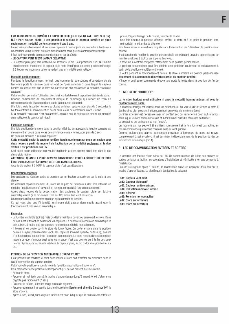
EXCLUSION CAPTEUR LUMIÈRE ET CAPTEUR PLUIE (SEULEMENT AVEC DIP3 SUR ON)N.B.: Part bouton câblé, il est possible d’exclure le capteur lumière et pluie seulement en modalité de fonctionnement pas à pas.La modalité positionnement et exclusion capteurs à pour objectif de permettre à l’utilisateur de contrôler le mouvement du store manuellement sans que les capteurs interviennent. Il faut tenir compte de quelques considérations sur la sûreté:- LE CAPTEUR VENT N’EST JAMAIS DÉSACTIVÉ.- Le capteur pluie peut être désactivé seulement si le dip 3 est positionné sur ON. Comme
précédemment mentionné, le capteur pluie reste inactif pour un temps prédéterminé égal à 2 heures ou jusqu’à ce qu’on ne revient pas en modalité automatique.
Modalité positionnementPendant le fonctionnement normal, une commande quelconque d’ouverture ou de fermeture porte la centrale dans un état de “positionnement” dans lequel le capteur lumière est exclue tant que le store ne s’arrêt et ne soit pas activée la modalité “exclusion capteurs”. Cette fonction permet à l’utilisateur de choisir confortablement la position désirée du store. Chaque commande de mouvement bloque le comptage qui repart de zéro en correspondance de chaque position stable (stop) ouvert ou fermé. Une fois choisie la position le store se bloque en tenant appuyer pour plus de 5 secondes le bouton contraire au mouvement en cours dans le cas de commande ouvre - ferme. Si la modalité “exclusion n’est pas activée”, après 5 sec. la centrale se reporte en modalité automatique et le capteur est rétabli.
Exclusion capteursUne fois positionnée le store dans la position désirée, en appuyant la touche contraire au mouvement en cours dans le cas de commande ouvre - ferme, pour plus de 5 sec. On entre en modalité “Exclusion capteurs”.Cette modalité exclut le capteur lumière, tandis que le capteur pluie est exclue pour deux heures a partir du moment de l’activation de la modalité seulement si le dip-switch 3 est positionné sur ON.Ceci parce qu’un utilisateur peut vouloir maintenir la tente ouverte aussi bien dans le cas d’une pluie légère.ATTENTION: QUAND LA PLUIE DEVIENT DANGEREUSE POUR LA STRUCTURE CE DOIT ÊTRE L’UTILISATEUR À FERMER LE STORE MANUELLEMENT.Avec le dip-switch 3 à l’OFF, le capteur pluie n’est pas désactivée.
Réactivation capteursLes capteurs se réactive après la pression sur un bouton poussoir ou par la suite à une alarme. Un éventuel repositionnement du store de la part de l’utilisateur doit être effectué en modalité “positionnement” et validé en rentrant en modalité “exclusion sensoriels”.Après deux heures de la désactivation des capteurs, le capteur pluie se réactive automatiquement (si le dip-switch 3 est sur ON, sinon il ne vient pas exclu).Le capteur lumière se réactive après un cycle complet de lumière. Ce qui veut dire que l’intensité lumineuse doit passer deux seuils avant que le fonctionnement retourne en automatique.
Exemples:- La lumière est faible (soirée) mais on désire maintenir ouvert ou entrouvert le store. Dans
ce cas il est suffisant de désactiver les capteurs. La centrale retournera en automatique le soir suivant, à moins que les capteurs ne soient pas rétablis manuellement.
- Il bruine et on désire ouvrir le store de toute façon; On porte le store dans la position désirée n ayant préalablement exclu les capteurs (comme spécifié ci-dessus), ensuite d’ici 5 secondes, on confirme l’exclusion des capteurs. Le store restera dans telle position jusqu’à ce que n’importe quel autre commande n’est pas donnée ou à la fin des deux heures. Après quoi la centrale rétablira le capteur pluie, le dip 3 doit être positionné sur ON.
POSITION DE LA “POSITION AUTOMATIQUE D’OUVERTURE”Il est possible de modifier le point dans lequel le store doit s’arrêter en ouverture dans le cas d’intervention du capteur lumière. Cette nouvelle position va sous le nom de “position automatique d’ouverture”. Pour mémoriser cette position il est important qu’il ne soit présent aucune alarme.- Fermer le store.- Appuyer et maintenir pressé la touche d’apprentissage jusqu’à quand le led d’alarme ne
clignote pas rapidement (7 sec.).- Relâcher la touche, le led led rouge arrête de clignoter.- Appuyer et maintenir pressé la touche d’ouverture (Seulement si le dip 2 est sur ON) le
store s’ouvre.- Après 4 sec, le led jaune clignote rapidement pour indiquer que la centrale est entrée en
phase d’apprentissage de la course, relâcher la touche.- Une fois atteinte la position désirée, arrêter le store et à ce point la position sera
mémorisée; le led arrête de clignoter.Si la tente arrive en ouverture complète sans l’intervention de l’utilisateur, la position vient effacée. Il est possible de modifier la position personnalisée en exécutant un autre apprentissage de manière analogue à tout ce qui à peine énoncée.Le reset de la centrale comporte l’effacement de la position personnalisée.La position personnalisée peut être atteinte avec précision seulement et exclusivement à partir de la position complètement fermé. En outre pendant le fonctionnement normal, le store s’arrêtera en position personnalisée seulement si la commande d’ouverture arrive du capteur lumière. N’importe quel autre commande d’ouverture porte la tente dans la position de fin de course.
E - MODALITÉ “HORLOGE”
La fonction horloge n’est utilisable ni avec la modalité homme présent ni avec le capteur lumière câblé.La modalité horloge est utilisée dans les situations ou on veut ouvrir et fermer le store à des horaires bien précis et indépendamment du niveau de lumière présent. Un timer extérieur est nécessaire avec un contact sec qui reste fermé pour tout le temps dans lequel le store doit rester ouvert et il doit s’ouvrir quand le store doit se fermer. Le contact va uni au bouton au mur “ouvre”. Les boutons au mur peuvent être utilisés normalement si la fonction n’est pas active, en cas de commande quelconque contraire celle-ci vient ignorée.Comme toujours une alarme quelconque provoque la fermeture du store qui rouvre complètement à peine celle-ci il est terminée, indépendamment de la position du dip de réouverture automatique (dip 1).
F - LED DE COMMUNICATION ENTRÉES ET SORTIES
La centrale est fournie d’une série de LED de communication de l’état des entrées et sorties de façon à faciliter les opérations d’installation et, vérifications en cas de panne à l’installation. Ces led s’éteignent après 1 minute, la réactivation arrive en appuyant deux fois sur la touche d’apprentissage. La signification des led est la suivante:
Led1: Capteur vent actifLed2: Capteur pluie actifLed3: Capteur lumière présentLed4: Utilisation mémoire interneLed5: RéservéLed6: Fonction horloge activeLed7: Store en fermetureLed8: Store en ouverture
F
14
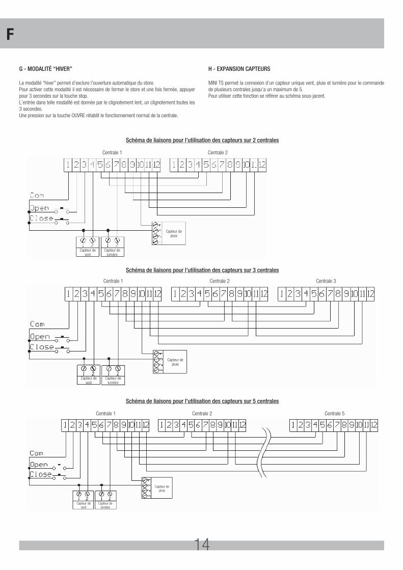
G - MODALITÉ “HIVER”
La modalité “hiver” permet d’exclure l’ouverture automatique du store. Pour activer cette modalité il est nécessaire de fermer le store et une fois fermée, appuyer pour 3 secondes sur la touche stop. L’entrée dans telle modalité est donnée par le clignotement lent, un clignotement toutes les 3 secondes. Une pression sur la touche OUVRE rétablit le fonctionnement normal de la centrale.
H - EXPANSION CAPTEURS
MINI TS permet la connexion d’un capteur unique vent, pluie et lumière pour le commande de plusieurs centrales jusqu’a un maximum de 5. Pour utiliser cette fonction se référer au schéma sous-jacent.
Capteur devent
Capteur depluie
Capteur delumière
Centrale 1 Centrale 2
Capteur devent
Capteur depluie
Capteur delumière
Centrale 1 Centrale 2 Centrale 3
Capteur devent
Capteur depluie
Capteur delumière
Centrale 1 Centrale 2 Centrale 5
Schéma de liaisons pour l’utilisation des capteurs sur 2 centrales
Schéma de liaisons pour l’utilisation des capteurs sur 3 centrales
Schéma de liaisons pour l’utilisation des capteurs sur 5 centrales
F
15
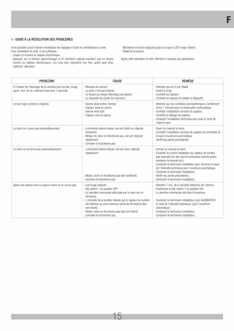
Il est possible à tout moment réinitialiser les réglages d’usine en réinitialisant la carte.Pour réinitialiser la carte, il est suffisante:- Couper le courant au tableau électronique.- Appuyez sur le bouton apprentissage et le maintenir appuyé pendant que on donne
tension au tableau électronique. Les trois leds clignotent une fois, après quoi elles resteront allumées.
- Maintenez le bouton appuyé jusqu’à ce que la LED rouge s’éteint.- Relâchez le bouton.
Après cette opération on doit effectuer à nouveau les paramètres.
PROBLÈME CAUSE REMÈDE
A l’instant de l’allumage de la centrale tous les led, rouge, jaune, vert, ils ne s’allument pas pour 1 seconde.
- Manque de courant.- La prise n’est pas insérée.- Le liaison au réseau électrique est absent.- Le dispositif de sûreté est intervenu.
- Attendre que qu’il soit rétabli.- Inséré la prise.- Contrôlé les liaisons.- Contrôlé les liaisons et rétablir le dispositif.
Le led rouge continue à clignote. - Alarme pluie active, trempé.- Capteur pluie en panne.- Alarme vent actif.- Capteur vent en panne.
- Attendre que les conditions atmosphériques s’améliorent et les 7 minutes pour la restauration automatique.
- Contrôlé l’installation correcte du capteur.- Contrôlé le câblage du capteur.- Contacté l’installateur technique pour lever le seuil de
l’alarme vent.
Le store ne s’ouvre pas automatiquement. - Luminosité externe basse, led vert éteint ou clignote lentement.
- Moteur du store ne fonctionne pas, led vert clignote rapidement.
- Centrale ne fonctionne pas.
- Ouvrir en manuel le store.- Contrôlé l’installation correcte du capteur de luminosité et
le seuil d’ouverture automatique.- Vérifié les points précédentes.
Le store ne se ferme pas automatiquement. - Luminosité externe élevée, led vert avec clignote rapidement.
- Moteur store ne fonctionne pas (led vertéteint).- Centrale ne fonctionne pas.
- Fermer en manuel le store.- Contrôler la correct installation du capteur de lumière
(par exemple loin des source lumineuse comme phare, enseigne lumineuse ect.).
- Contacter le technicien installateur pour diminuer la seuil de l’intensité lumineuse pour l’ouverture automatique.
- Contacter le technicien installateur.- Vérifié les points précédentes.- Contacter le technicien installateur.
Après une alarme vent ou pluie le store ne se rouvre pas. - Led rouge clignote.- Dip-switch 1 en position OFF.- La dernière commande effectuée par le store est un
fermeture.- L’intensité de la lumière relevée par le capteur de lumière
est inférieur au seuil minimum (seuil de fermeture) (led vert éteint).
- Moteur store ne fonctionne pas (led vert éteint).- Centrale ne fonctionne pas.
- Attendre 7 min. de la dernière détection de l’alarme.- Positionner le Dip-switch 1 en position ON.- La dernière commande doit être d’ouverture.
- Contacter le technicien installateur pour AUGMENTER le seuil de l’intensité lumineuse pour l’ouverture automatique.
- Contacter le technicien installateur.- Contacter le technicien installateur.
I - GUIDE À LA RÉSOLUTION DES PROBLÈMES
F
16
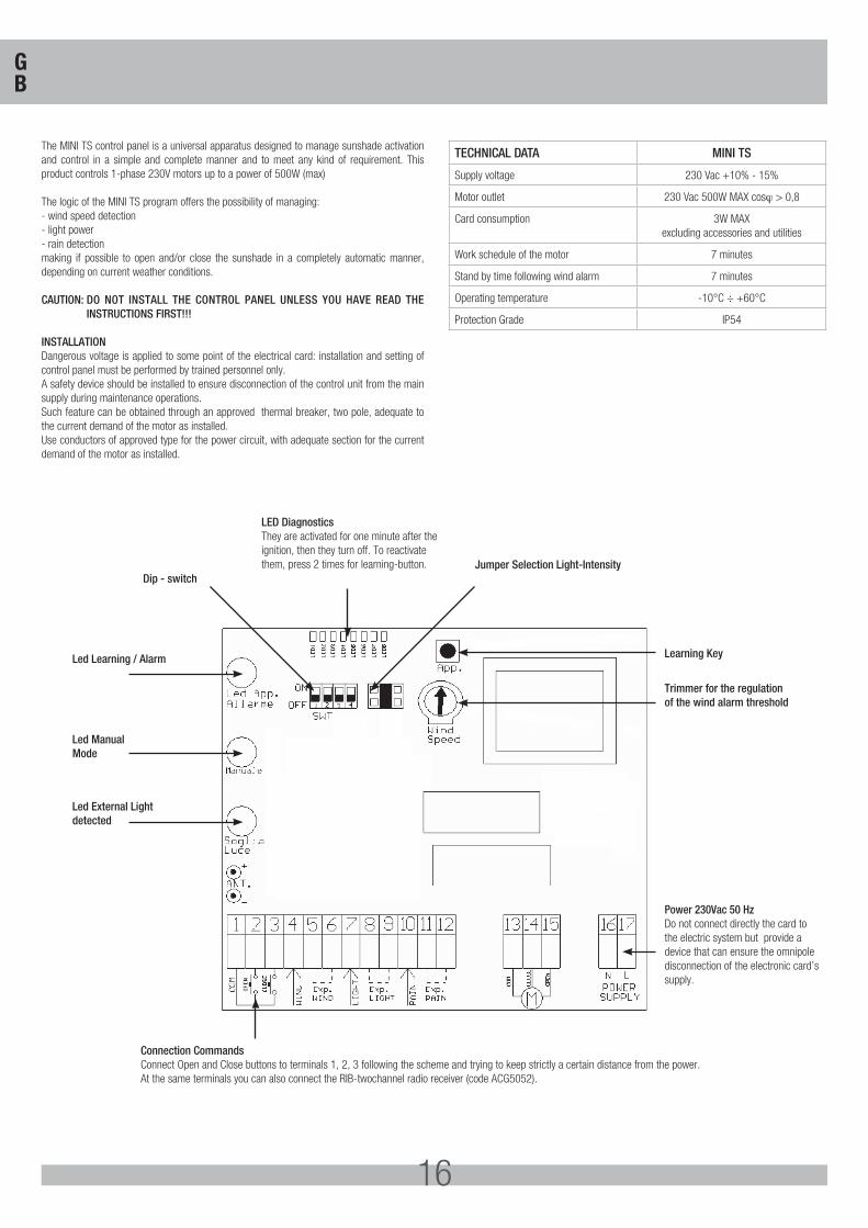
The MINI TS control panel is a universal apparatus designed to manage sunshade activation and control in a simple and complete manner and to meet any kind of requirement. This product controls 1-phase 230V motors up to a power of 500W (max)
The logic of the MINI TS program offers the possibility of managing:- wind speed detection- light power- rain detectionmaking if possible to open and/or close the sunshade in a completely automatic manner, depending on current weather conditions.
CAUTION: DO NOT INSTALL THE CONTROL PANEL UNLESS YOU HAVE READ THE INSTRUCTIONS FIRST!!!
INSTALLATIONDangerous voltage is applied to some point of the electrical card: installation and setting of control panel must be performed by trained personnel only.A safety device should be installed to ensure disconnection of the control unit from the main supply during maintenance operations.Such feature can be obtained through an approved thermal breaker, two pole, adequate to the current demand of the motor as installed.Use conductors of approved type for the power circuit, with adequate section for the current demand of the motor as installed.
TECHNICAL DATA MINI TS
Supply voltage 230 Vac +10% - 15%
Motor outlet 230 Vac 500W MAX cosϕ > 0,8
Card consumption 3W MAX excluding accessories and utilities
Work schedule of the motor 7 minutes
Stand by time following wind alarm 7 minutes
Operating temperature -10°C ÷ +60°C
Protection Grade IP54
LED Diagnostics They are activated for one minute after the ignition, then they turn off. To reactivate them, press 2 times for learning-button.
Connection Commands Connect Open and Close buttons to terminals 1, 2, 3 following the scheme and trying to keep strictly a certain distance from the power. At the same terminals you can also connect the RIB-twochannel radio receiver (code ACG5052).
Led Learning / Alarm Learning Key
Trimmer for the regulation of the wind alarm threshold
Power 230Vac 50 HzDo not connect directly the card to the electric system but provide a device that can ensure the omnipole disconnection of the electronic card’s supply.
Dip - switchJumper Selection Light-Intensity
Led Manual Mode
Led External Lightdetected
GB
17
MINI TS control unit is equipped with a control panel, with which it is possible to monitor its state of working. The control panel is composed by three lighting warning lights (led):- green warning light that indicates the intensity of the light;- yellow warning light that indicates the functioning on setting “positioning” and “sensors
exclusion”;- red warning light that indicates the alarm condition.By these luminous indicators, it is possible to verify the correct functioning of the control unit and identify the possible malfunctioning.When voltage is given to the control unit, all the three indicators led will rest lighted up for one second, then they will execute 3 blinking.
After few seconds, if the sensor of the luminous intensity is present, the green led will start to blink in a different way according to the intensity of the light registered. With this led it is quite possible to execute the regulation of the luminous intensity for the automatic opening of the sunshade. In the case in which a condition of alarm is present (wind or rain), the red led will start to blink for the complete period of alarm (about 7 min.).The yellow led indicates the functioning of the device on positioning mode and sensor exclusion according to the way in which it blinks.
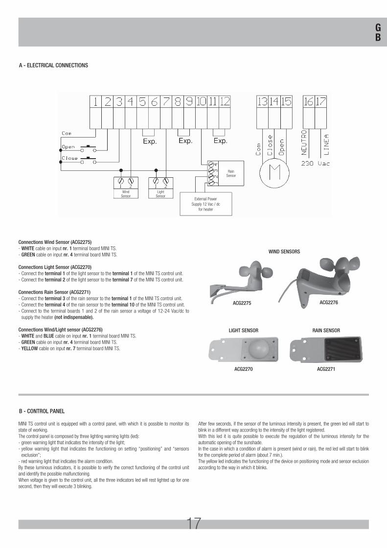
A - ELECTRICAL CONNECTIONS
B - CONTROL PANEL
WindSensor
RainSensor
External PowerSupply 12 Vac / dc
for heater
LightSensor
Connections Wind Sensor (ACG2275)- WHITE cable on input nr. 1 terminal board MINI TS.- GREEN cable on input nr. 4 terminal board MINI TS.
Connections Light Sensor (ACG2270)- Connect the terminal 1 of the light sensor to the terminal 1 of the MINI TS control unit.- Connect the terminal 2 of the light sensor to the terminal 7 of the MINI TS control unit.
Connections Rain Sensor (ACG2271)- Connect the terminal 3 of the rain sensor to the terminal 1 of the MINI TS control unit.- Connect the terminal 4 of the rain sensor to the terminal 10 of the MINI TS control unit.- Connect to the terminal boards 1 and 2 of the rain sensor a voltage of 12-24 Vac/dc to
supply the heater (not indispensable).
Connections Wind/Light sensor (ACG2276)- WHITE and BLUE cable on input nr. 1 terminal board MINI TS. - GREEN cable on input nr. 4 terminal board MINI TS.- YELLOW cable on input nr. 7 terminal board MINI TS.
WIND SENSORS
LIGHT SENSOR
ACG2270
RAIN SENSOR
ACG2271
ACG2275 ACG2276
GB
18
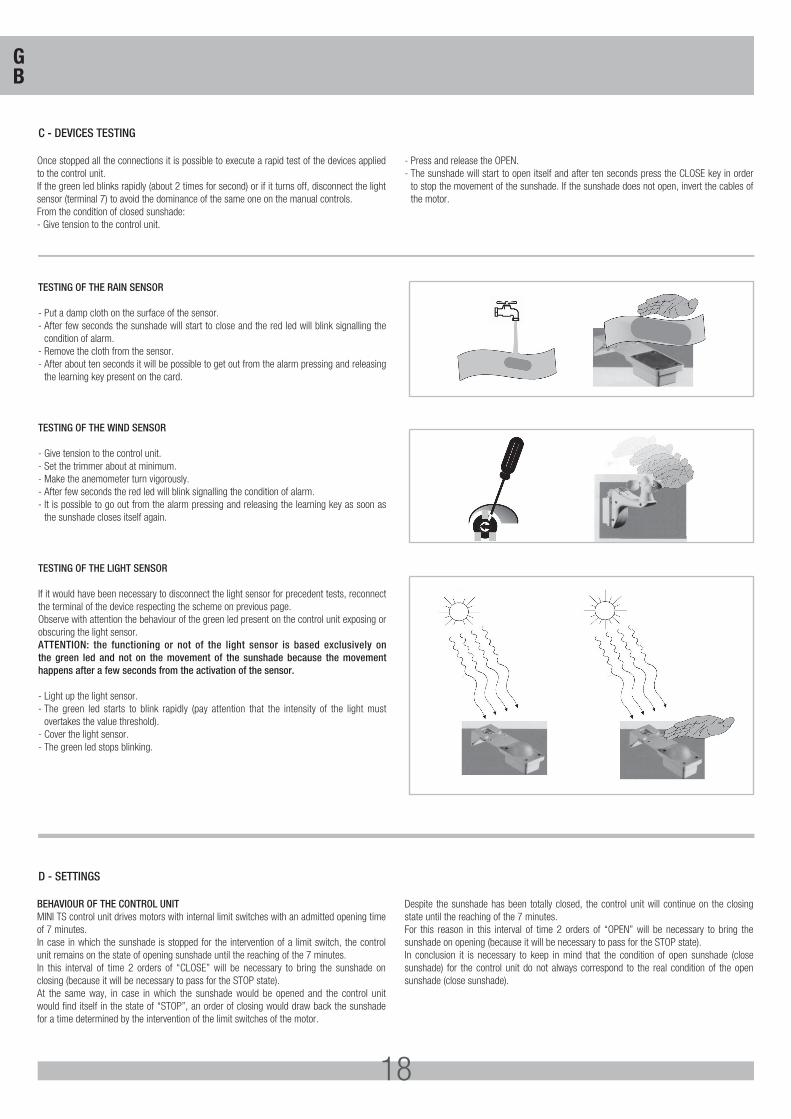
TESTING OF THE RAIN SENSOR
- Put a damp cloth on the surface of the sensor.- After few seconds the sunshade will start to close and the red led will blink signalling the
condition of alarm.- Remove the cloth from the sensor.- After about ten seconds it will be possible to get out from the alarm pressing and releasing
the learning key present on the card.
TESTING OF THE WIND SENSOR
- Give tension to the control unit.- Set the trimmer about at minimum.- Make the anemometer turn vigorously.- After few seconds the red led will blink signalling the condition of alarm.- It is possible to go out from the alarm pressing and releasing the learning key as soon as
the sunshade closes itself again.
TESTING OF THE LIGHT SENSOR
If it would have been necessary to disconnect the light sensor for precedent tests, reconnect the terminal of the device respecting the scheme on previous page.Observe with attention the behaviour of the green led present on the control unit exposing or obscuring the light sensor.ATTENTION: the functioning or not of the light sensor is based exclusively on the green led and not on the movement of the sunshade because the movement happens after a few seconds from the activation of the sensor.
- Light up the light sensor.- The green led starts to blink rapidly (pay attention that the intensity of the light must
overtakes the value threshold).- Cover the light sensor.- The green led stops blinking.
Once stopped all the connections it is possible to execute a rapid test of the devices applied to the control unit. If the green led blinks rapidly (about 2 times for second) or if it turns off, disconnect the light sensor (terminal 7) to avoid the dominance of the same one on the manual controls. From the condition of closed sunshade:- Give tension to the control unit.
- Press and release the OPEN.- The sunshade will start to open itself and after ten seconds press the CLOSE key in order
to stop the movement of the sunshade. If the sunshade does not open, invert the cables of the motor.
BEHAVIOUR OF THE CONTROL UNITMINI TS control unit drives motors with internal limit switches with an admitted opening time of 7 minutes. In case in which the sunshade is stopped for the intervention of a limit switch, the control unit remains on the state of opening sunshade until the reaching of the 7 minutes.In this interval of time 2 orders of “CLOSE” will be necessary to bring the sunshade on closing (because it will be necessary to pass for the STOP state).At the same way, in case in which the sunshade would be opened and the control unit would find itself in the state of “STOP”, an order of closing would draw back the sunshade for a time determined by the intervention of the limit switches of the motor.
Despite the sunshade has been totally closed, the control unit will continue on the closing state until the reaching of the 7 minutes. For this reason in this interval of time 2 orders of “OPEN” will be necessary to bring the sunshade on opening (because it will be necessary to pass for the STOP state).In conclusion it is necessary to keep in mind that the condition of open sunshade (close sunshade) for the control unit do not always correspond to the real condition of the open sunshade (close sunshade).
C - DEVICES TESTING
D - SETTINGS
GB
19
SELECTION OF THE FUNCTIONSSetting the selection of function (dip – switch) and the adjusting device (trimmer) present in the control unit, several types of functioning are possible. MINI TS is supplied with the following settings:- Wind threshold at 30 Km/h- Opening time at maximum = 7 min.- Closing time at maximum = 7 min- All the dip on off (NOTE: to the Dip 4 are not associated functions)- Light 2 threshold (intermediate)Applying several devices for “environmental” control (anemometer, sensor of luminous intensity, rain sensor), it is possible to execute some furtheradjustments, some of them by acting directly on the card.
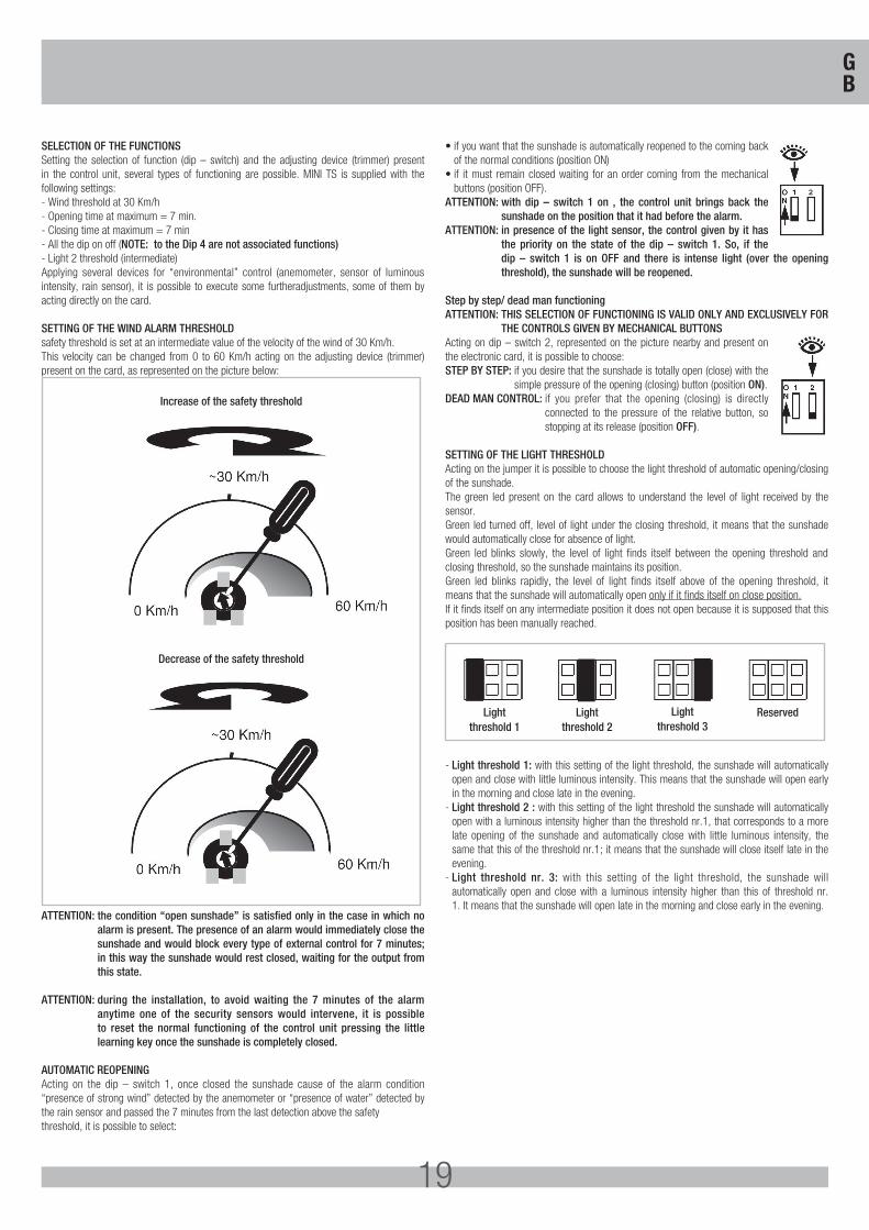
SETTING OF THE WIND ALARM THRESHOLDsafety threshold is set at an intermediate value of the velocity of the wind of 30 Km/h. This velocity can be changed from 0 to 60 Km/h acting on the adjusting device (trimmer) present on the card, as represented on the picture below:
Increase of the safety threshold
Decrease of the safety threshold
ATTENTION: the condition “open sunshade” is satisfied only in the case in which no alarm is present. The presence of an alarm would immediately close the sunshade and would block every type of external control for 7 minutes; in this way the sunshade would rest closed, waiting for the output from this state.
ATTENTION: during the installation, to avoid waiting the 7 minutes of the alarm anytime one of the security sensors would intervene, it is possible to reset the normal functioning of the control unit pressing the little learning key once the sunshade is completely closed.
AUTOMATIC REOPENINGActing on the dip – switch 1, once closed the sunshade cause of the alarm condition “presence of strong wind” detected by the anemometer or “presence of water” detected by the rain sensor and passed the 7 minutes from the last detection above the safetythreshold, it is possible to select:
• if you want that the sunshade is automatically reopened to the coming back of the normal conditions (position ON)
• if it must remain closed waiting for an order coming from the mechanical buttons (position OFF).
ATTENTION: with dip – switch 1 on , the control unit brings back the sunshade on the position that it had before the alarm.
ATTENTION: in presence of the light sensor, the control given by it has the priority on the state of the dip – switch 1. So, if the dip – switch 1 is on OFF and there is intense light (over the opening threshold), the sunshade will be reopened.
Step by step/ dead man functioningATTENTION: THIS SELECTION OF FUNCTIONING IS VALID ONLY AND EXCLUSIVELY FOR
THE CONTROLS GIVEN BY MECHANICAL BUTTONSActing on dip – switch 2, represented on the picture nearby and present on the electronic card, it is possible to choose:STEP BY STEP: if you desire that the sunshade is totally open (close) with the
simple pressure of the opening (closing) button (position ON).DEAD MAN CONTROL: if you prefer that the opening (closing) is directly
connected to the pressure of the relative button, so stopping at its release (position OFF).
SETTING OF THE LIGHT THRESHOLDActing on the jumper it is possible to choose the light threshold of automatic opening/closing of the sunshade. The green led present on the card allows to understand the level of light received by the sensor. Green led turned off, level of light under the closing threshold, it means that the sunshade would automatically close for absence of light.Green led blinks slowly, the level of light finds itself between the opening threshold and closing threshold, so the sunshade maintains its position.Green led blinks rapidly, the level of light finds itself above of the opening threshold, it means that the sunshade will automatically open only if it finds itself on close position.If it finds itself on any intermediate position it does not open because it is supposed that this position has been manually reached.
Light threshold 1
Light threshold 2
Light threshold 3
Reserved
- Light threshold 1: with this setting of the light threshold, the sunshade will automatically open and close with little luminous intensity. This means that the sunshade will open early in the morning and close late in the evening.
- Light threshold 2 : with this setting of the light threshold the sunshade will automatically open with a luminous intensity higher than the threshold nr.1, that corresponds to a more late opening of the sunshade and automatically close with little luminous intensity, the same that this of the threshold nr.1; it means that the sunshade will close itself late in the evening.
- Light threshold nr. 3: with this setting of the light threshold, the sunshade will automatically open and close with a luminous intensity higher than this of threshold nr. 1. It means that the sunshade will open late in the morning and close early in the evening.
GB
20
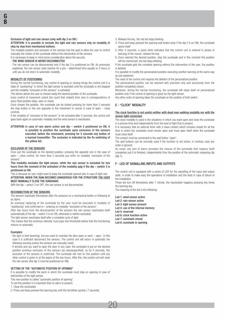
Exclusion of light and rain sensor (only with dip 3 on ON )ATTENTION: it is possible to exclude the light and rain sensors only on modality of step by step from mechanical buttons.The modality position and exclusion of the sensors has the goal to allow the user to control manually the motion of the sunshade without the intervention of the sensors.It is necessary to keep in mind some consideration about the security:- THE WIND SENSOR IS NEVER DISCONNECTED- The rain sensor can be disconnected only if the dip 3 is positioned on ON. As previously
explained, the rain sensor rests inactive for a pre – determined time equally to 2 hours or until you do not return in automatic modality.
MODALITY OF POSITIONINGDuring the normal functioning, any control of opening or closing brings the control unit in a state of “positioning” in which the light sensor is excluded until the sunshade is not stopped and the modality “exclusion of the sensors” is activated.This device allows the user to choose easily the desired position of the sunshade.Every control of movement unlock the count that restarts from zero in correspondence of every fixed position (stop, open or close). Once chosen the position, the sunshade can be locked pressing for more than 5 seconds the stop button or the one opposite to the movement in course in case of open – close controls.If the modality of “exclusion of the sensors” is not activated after 5 seconds, the control unit goes back again on automatic modality and the wind sensor is reactivated.
ATTENTION: in case of rain alarm active and dip – switch 3 positioned on ON, it is possible to position the sunshade upon exclusion of the sensors executed, before the movement, pressing for 5 seconds any button of a learned transmitter. The exclusion is indicated by the fix switching of the yellow led.
EXCLUSION OF THE SENSORSOnce put the sunshade on the desired position, pressing the opposite one in the case of open – close control, for more than 5 seconds you enter on modality “exclusion of the sensors”.This modality excludes the light sensor, while the rain sensor is excluded for two hours from the moment of the activation of the modality only if the dip – switch 3 is positioned on ON.This is because an user might want to keep the sunshade opened also in case of light rain.ATTENTION: WHEN THE RAIN BECOMES DANGEROUS FOR THE STRUCTURE THE USER MUST MANUALLY CLOSE THE SUNSHADE.With the dip – switch 3 on OFF, the rain sensor is not disconnected.
RECONNECTION OF THE SENSORSThe sensors reactivate themselves after the pressure on a mechanical button or following to an alarm.An eventual replacing of the sunshade by the user must be executed in modality of “positioning” and confirmed re – entering on modality “exclusion of the sensors”.After two hours from the disconnection of the sensors the rain sensor reactivates itself automatically (if the dip – switch 3 is on ON, otherwise is neither excluded).The light sensor reactivates itself after a complete cycle of light. This means that the luminous intensity must pass two thresholds before that the functioning returns on automatic.
Examples:- the light is faint (evening), but you want to maintain the door open or semi – open . In this
case it is sufficient disconnect the sensors. The control unit will return in automatic the following evening (unless the sensors are manually reset).
- It drizzles and you want to open the door in any case; the sunshade is put on the desired position previous exclusion of the sensors (as abovespecified), so by 5 seconds, the exclusion of the sensors is confirmed. The sunshade will rest on this position until any other control is given or at the expire of the two hours. After this, the control unit will reset the rain sensor (the dip 3 must be positioned on ON).
SETTING OF THE “AUTOMATIC POSITION OF OPENING”It is possible to modify the point in which the sunshade must stop on opening in case of intervention of the light sensor. This new position is called “automatic position of opening”. To set this position it is important that no alarm is present.1. Close the sunshades2. Press and keep pressed the learning key until the led blinks quickly ( 7 seconds)
3. Release the key, the red led stops blinking4. Press and keep pressed the opening wall button (only if the dip 2 is on ON); the sunshade
opens itself5. After 4 seconds, a quick blink indicates that the control unit is entered in phase of
learning of the course, release the key.6. Once reached the desired position, stop the sunshade and in this moment this position
will be memorized; the led stops blinkingIf the sunshade gets the complete opening without the intervention of the user, the position is deleted. It is possible to modify the personalized position executing another learning at the same way as just explained.The reset of the control unit requires the deletion of the personalized position.The personalized position can be reached with precision only and exclusively from the position completely closed. Moreover, during the normal functioning, the sunshade will stops itself on personalized position only if the control of opening is given by the light sensor. Any other order of opening takes the sunshade on the position of limit switch.
E - “CLOCK” MODALITY
The clock function is not useful neither with dead man walking modality nor with the sensor light connected.The clock modality is used in the situations in which you want open and close the sunshade in a precise time and independently from the level of light that is present. It is necessary that an external timer with a clean contact which remains closed for all the time in which the sunshade must remain open and must open itself when the sunshade must close itself. The contact must be connected to the wall button “open”. The wall buttons can be normally used if the function is not active, in contrary case any order is ignored.As usual, any sort of alarm provokes the closure of the sunshade that reopens itself completely just it is finished, independently from the position of the automatic reopening dip (dip 1).
F - LED OF SIGNALLING INPUTS AND OUTPUTS
The control unit is equipped with a series of LED for the signalling of the input and output state, in order to make easy the operations of installation and the tests in case of failure of the installation.These led turn off themselves after 1 minute, the reactivation happens pressing two times the learning key. The meaning of the led is the following:
Led 1: wind sensor activeLed 2: rain sensor activeLed 3: light sensor presentLed 4: use of the internal memoryLed 5: reservedLed 6: clock function activeLed 7: sunshade closedLed 8: sunshade in opening
GB
21
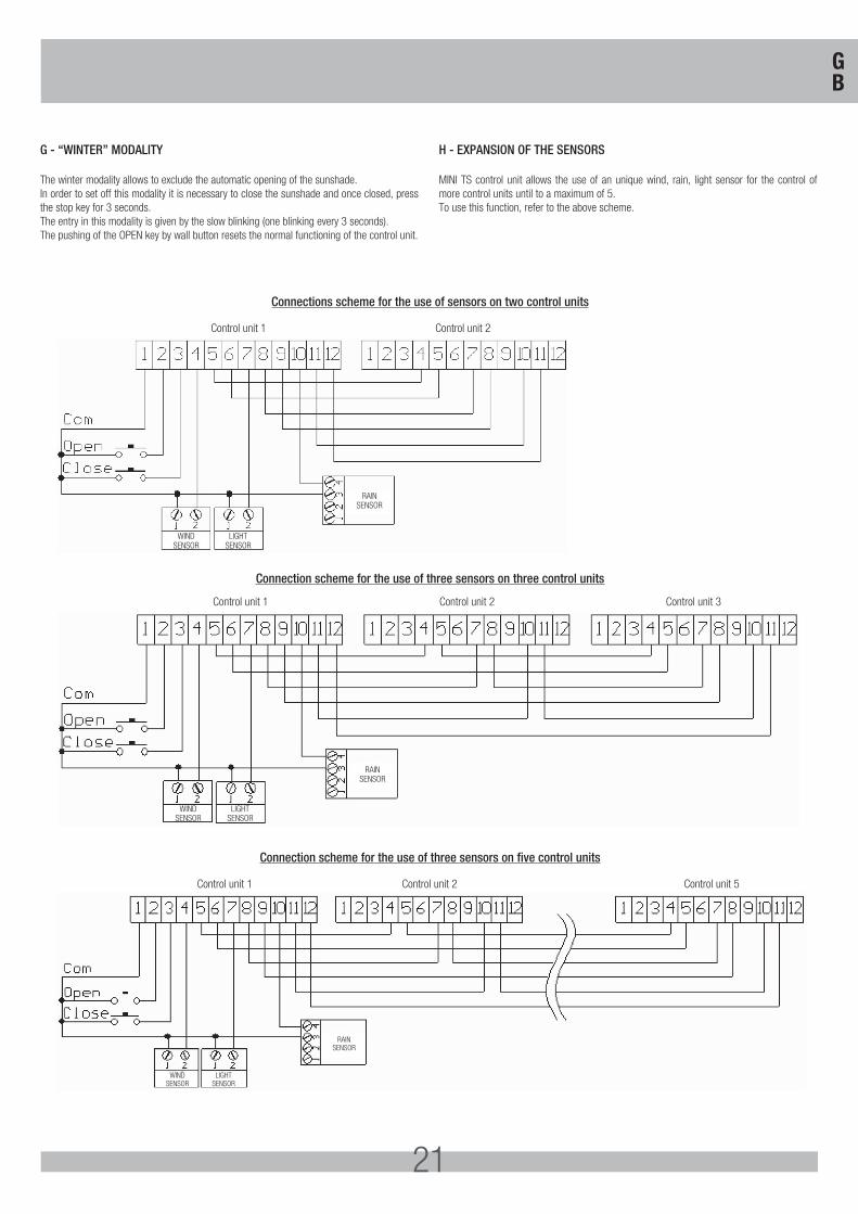
G - “WINTER” MODALITY
The winter modality allows to exclude the automatic opening of the sunshade. In order to set off this modality it is necessary to close the sunshade and once closed, press the stop key for 3 seconds. The entry in this modality is given by the slow blinking (one blinking every 3 seconds). The pushing of the OPEN key by wall button resets the normal functioning of the control unit.
H - EXPANSION OF THE SENSORS
MINI TS control unit allows the use of an unique wind, rain, light sensor for the control of more control units until to a maximum of 5.To use this function, refer to the above scheme.
WINDSENSOR
RAINSENSOR
LIGHTSENSOR
Control unit 1 Control unit 2
WINDSENSOR
RAINSENSOR
LIGHTSENSOR
Control unit 1 Control unit 2 Control unit 3
WINDSENSOR
RAINSENSOR
LIGHTSENSOR
Control unit 1 Control unit 2 Control unit 5
Connections scheme for the use of sensors on two control units
Connection scheme for the use of three sensors on three control units
Connection scheme for the use of three sensors on five control units
GB
22
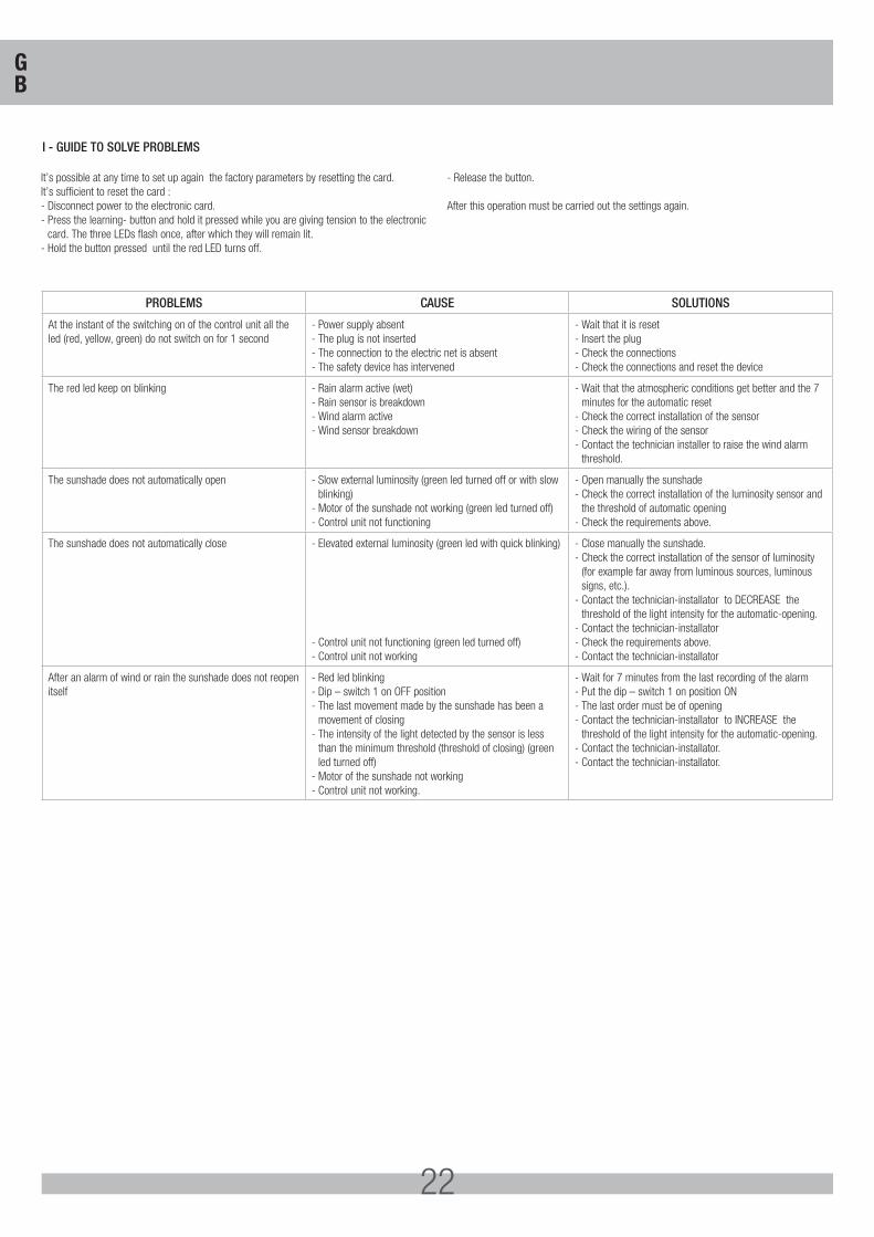
It’s possible at any time to set up again the factory parameters by resetting the card.It’s sufficient to reset the card :- Disconnect power to the electronic card.- Press the learning- button and hold it pressed while you are giving tension to the electronic
card. The three LEDs flash once, after which they will remain lit.- Hold the button pressed until the red LED turns off.
- Release the button.
After this operation must be carried out the settings again.
PROBLEMS CAUSE SOLUTIONS
At the instant of the switching on of the control unit all the led (red, yellow, green) do not switch on for 1 second
- Power supply absent- The plug is not inserted- The connection to the electric net is absent- The safety device has intervened
- Wait that it is reset- Insert the plug- Check the connections- Check the connections and reset the device
The red led keep on blinking - Rain alarm active (wet)- Rain sensor is breakdown- Wind alarm active- Wind sensor breakdown
- Wait that the atmospheric conditions get better and the 7 minutes for the automatic reset
- Check the correct installation of the sensor- Check the wiring of the sensor - Contact the technician installer to raise the wind alarm
threshold.
The sunshade does not automatically open - Slow external luminosity (green led turned off or with slow blinking)
- Motor of the sunshade not working (green led turned off)- Control unit not functioning
- Open manually the sunshade- Check the correct installation of the luminosity sensor and
the threshold of automatic opening- Check the requirements above.
The sunshade does not automatically close - Elevated external luminosity (green led with quick blinking)
- Control unit not functioning (green led turned off)- Control unit not working
- Close manually the sunshade.- Check the correct installation of the sensor of luminosity
(for example far away from luminous sources, luminous signs, etc.).
- Contact the technician-installator to DECREASE the threshold of the light intensity for the automatic-opening.
- Contact the technician-installator - Check the requirements above.- Contact the technician-installator
After an alarm of wind or rain the sunshade does not reopen itself
- Red led blinking- Dip – switch 1 on OFF position- The last movement made by the sunshade has been a
movement of closing- The intensity of the light detected by the sensor is less
than the minimum threshold (threshold of closing) (green led turned off)
- Motor of the sunshade not working- Control unit not working.
- Wait for 7 minutes from the last recording of the alarm- Put the dip – switch 1 on position ON- The last order must be of opening- Contact the technician-installator to INCREASE the
threshold of the light intensity for the automatic-opening.- Contact the technician-installator.- Contact the technician-installator.
I - GUIDE TO SOLVE PROBLEMS
GB
23
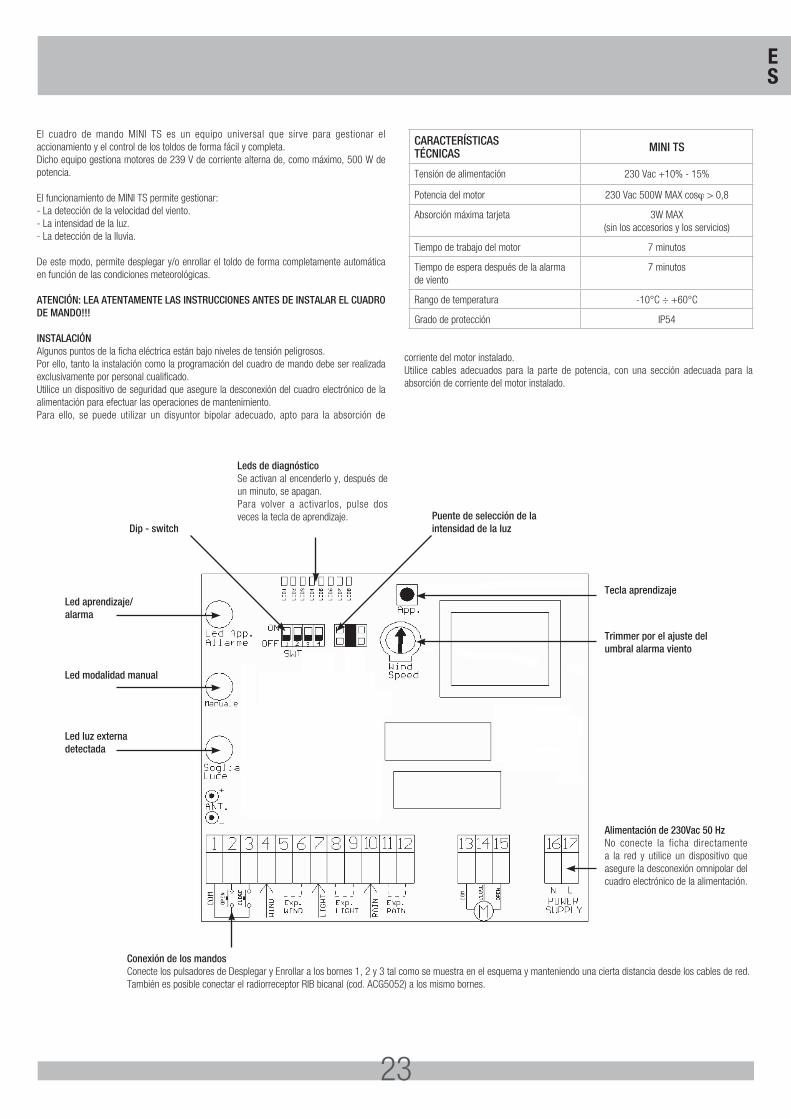
El cuadro de mando MINI TS es un equipo universal que sirve para gestionar el accionamiento y el control de los toldos de forma fácil y completa. Dicho equipo gestiona motores de 239 V de corriente alterna de, como máximo, 500 W de potencia. El funcionamiento de MINI TS permite gestionar:- La detección de la velocidad del viento.- La intensidad de la luz.- La detección de la lluvia. De este modo, permite desplegar y/o enrollar el toldo de forma completamente automática en función de las condiciones meteorológicas.
ATENCIÓN: LEA ATENTAMENTE LAS INSTRUCCIONES ANTES DE INSTALAR EL CUADRO DE MANDO!!!
INSTALACIÓNAlgunos puntos de la ficha eléctrica están bajo niveles de tensión peligrosos. Por ello, tanto la instalación como la programación del cuadro de mando debe ser realizada exclusivamente por personal cualificado. Utilice un dispositivo de seguridad que asegure la desconexión del cuadro electrónico de la alimentación para efectuar las operaciones de mantenimiento.Para ello, se puede utilizar un disyuntor bipolar adecuado, apto para la absorción de
corriente del motor instalado. Utilice cables adecuados para la parte de potencia, con una sección adecuada para la absorción de corriente del motor instalado.
CARACTERÍSTICASTÉCNICAS MINI TS
Tensión de alimentación 230 Vac +10% - 15%
Potencia del motor 230 Vac 500W MAX cosϕ > 0,8
Absorción máxima tarjeta 3W MAX (sin los accesorios y los servicios)
Tiempo de trabajo del motor 7 minutos
Tiempo de espera después de la alarma de viento
7 minutos
Rango de temperatura -10°C ÷ +60°C
Grado de protección IP54
Leds de diagnóstico Se activan al encenderlo y, después de un minuto, se apagan. Para volver a activarlos, pulse dos veces la tecla de aprendizaje.
Conexión de los mandosConecte los pulsadores de Desplegar y Enrollar a los bornes 1, 2 y 3 tal como se muestra en el esquema y manteniendo una cierta distancia desde los cables de red. También es posible conectar el radiorreceptor RIB bicanal (cod. ACG5052) a los mismo bornes.
Led aprendizaje/alarma
Tecla aprendizaje
Trimmer por el ajuste del umbral alarma viento
Alimentación de 230Vac 50 HzNo conecte la ficha directamente a la red y utilice un dispositivo que asegure la desconexión omnipolar del cuadro electrónico de la alimentación.
Dip - switchPuente de selección de la intensidad de la luz
Led modalidad manual
Led luz externadetectada
ES
24
El cuadro de control MINI TS lleva un panel de control con el cual es posible monitorear su estado de funcionamiento. El tablero de control se compone por tres luces testigo (LED):• luz testigo verde que señala la intensidad de la luz• luz testigo amarilla que indica el funcionamiento en modalidad “posicionamiento” y
“exclusión sensores”• luz testigo roja que señala la condición de alarmaCon estos indicadores luminosos se puede verificar el correcto funciónamiento del cuadro de control y individuar los posibles malfunciónamientos.Cuando se dá tensión al cuadro de control, todos los tres indicadores se quedarán encendidos por 1 segundo y despúes efectuarán 3 destellos.Después de algunos segundos, si es presente el sensor de intensidad luminosa, el led verde empezará a destellar en manera diferente según la intensidad de luz registrada.
Con este led es posible efectuar el ajuste de la intensidad luminosa para la apertura automática del toldo.En el caso en que se presente una condición de alarma (viento o lluvia), el led rojo empezará a destellar por todo el tiempo de alarma (más o menos 7 min.).El led amarillo señala el funcionamiento del dispositivo en modalidad de posicionamiento y exclusión sensores según como el destella.
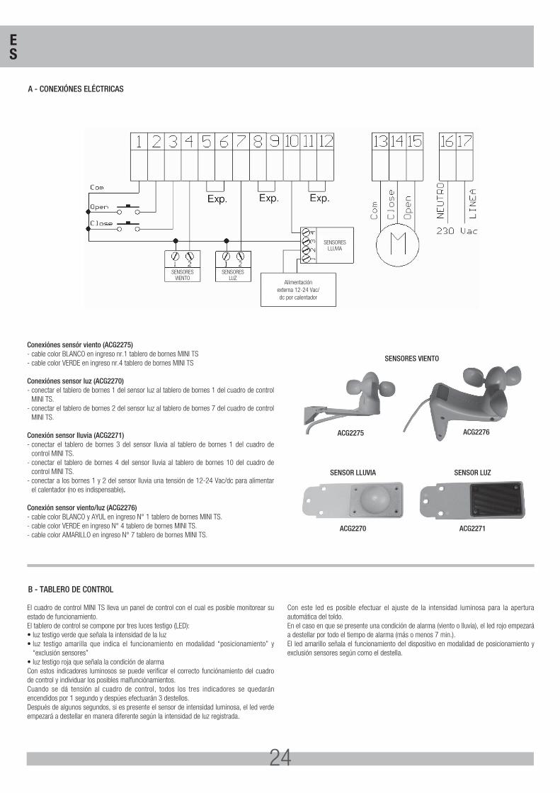
A - CONEXIÓNES ELÉCTRICAS
B - TABLERO DE CONTROL
SENSORESVIENTO
SENSORESLLUVIA
Alimentaciónexterna 12-24 Vac/dc por calentador
SENSORESLUZ
Conexiónes sensór viento (ACG2275)- cable color BLANCO en ingreso nr.1 tablero de bornes MINI TS- cable color VERDE en ingreso nr.4 tablero de bornes MINI TS
Conexiónes sensor luz (ACG2270)- conectar el tablero de bornes 1 del sensor luz al tablero de bornes 1 del cuadro de control
MINI TS.- conectar el tablero de bornes 2 del sensor luz al tablero de bornes 7 del cuadro de control
MINI TS.
Conexión sensor lluvia (ACG2271)- conectar el tablero de bornes 3 del sensor lluvia al tablero de bornes 1 del cuadro de
control MINI TS.- conectar el tablero de bornes 4 del sensor lluvia al tablero de bornes 10 del cuadro de
control MINI TS.- conectar a los bornes 1 y 2 del sensor lluvia una tensión de 12-24 Vac/dc para alimentar
el calentador (no es indispensable).
Conexión sensor viento/luz (ACG2276)- cable color BLANCO y AYUL en ingreso N° 1 tablero de bornes MINI TS.- cable color VERDE en ingreso N° 4 tablero de bornes MINI TS.- cable color AMARILLO en ingreso N° 7 tablero de bornes MINI TS.
SENSORES VIENTO
SENSOR LLUVIA
ACG2270
SENSOR LUZ
ACG2271
ACG2275 ACG2276
ES
25
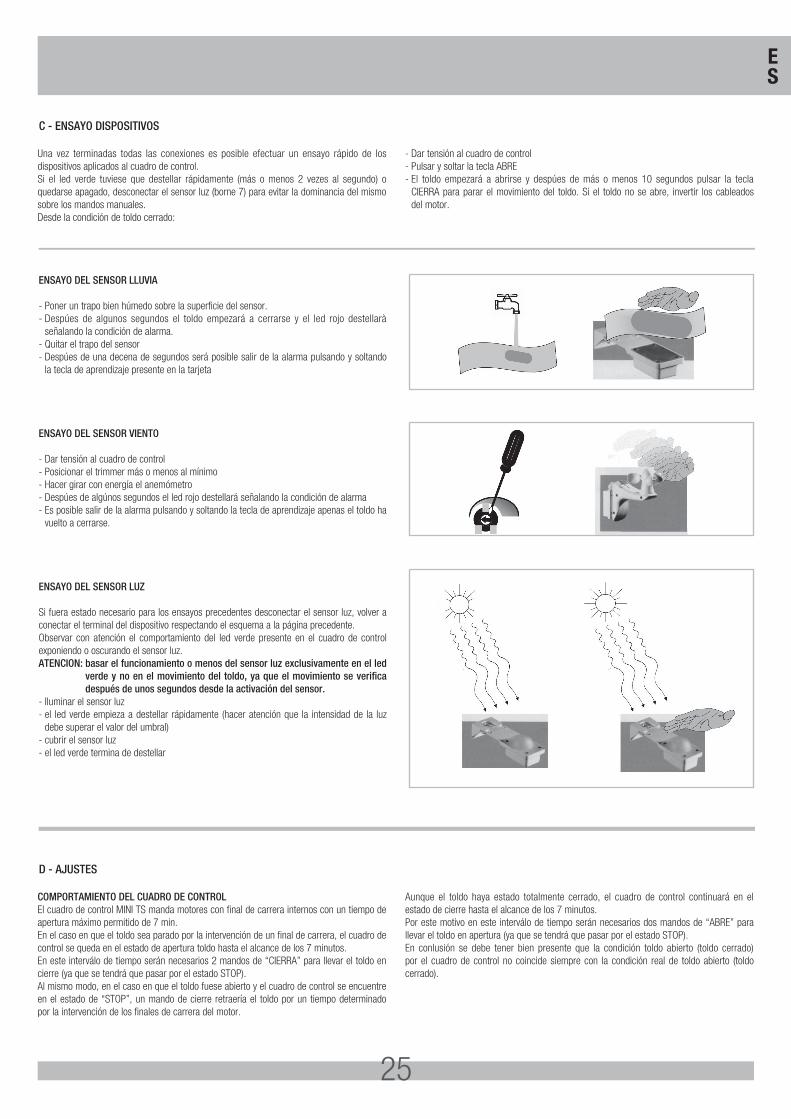
ENSAYO DEL SENSOR LLUVIA
- Poner un trapo bien húmedo sobre la superficie del sensor.- Despúes de algunos segundos el toldo empezará a cerrarse y el led rojo destellarà
señalando la condición de alarma.- Quitar el trapo del sensor- Despúes de una decena de segundos será posible salir de la alarma pulsando y soltando
la tecla de aprendizaje presente en la tarjeta
ENSAYO DEL SENSOR VIENTO
- Dar tensión al cuadro de control- Posicionar el trimmer más o menos al mínimo- Hacer girar con energía el anemómetro- Despúes de algúnos segundos el led rojo destellará señalando la condición de alarma- Es posible salir de la alarma pulsando y soltando la tecla de aprendizaje apenas el toldo ha
vuelto a cerrarse.
ENSAYO DEL SENSOR LUZ
Si fuera estado necesario para los ensayos precedentes desconectar el sensor luz, volver a conectar el terminal del dispositivo respectando el esquema a la página precedente.Observar con atención el comportamiento del led verde presente en el cuadro de control exponiendo o oscurando el sensor luz.ATENCION: basar el funcionamiento o menos del sensor luz exclusivamente en el led
verde y no en el movimiento del toldo, ya que el movimiento se verifica después de unos segundos desde la activación del sensor.
- Iluminar el sensor luz- el led verde empieza a destellar rápidamente (hacer atención que la intensidad de la luz
debe superar el valor del umbral)- cubrir el sensor luz- el led verde termina de destellar
Una vez terminadas todas las conexiones es posible efectuar un ensayo rápido de los dispositivos aplicados al cuadro de control. Si el led verde tuviese que destellar rápidamente (más o menos 2 vezes al segundo) o quedarse apagado, desconectar el sensor luz (borne 7) para evitar la dominancia del mismo sobre los mandos manuales. Desde la condición de toldo cerrado:
- Dar tensión al cuadro de control- Pulsar y soltar la tecla ABRE- El toldo empezará a abrirse y despúes de más o menos 10 segundos pulsar la tecla
CIERRA para parar el movimiento del toldo. Si el toldo no se abre, invertir los cableados del motor.
COMPORTAMIENTO DEL CUADRO DE CONTROLEl cuadro de control MINI TS manda motores con final de carrera internos con un tiempo de apertura máximo permitido de 7 min.En el caso en que el toldo sea parado por la intervención de un final de carrera, el cuadro de control se queda en el estado de apertura toldo hasta el alcance de los 7 minutos. En este interválo de tiempo serán necesarios 2 mandos de “CIERRA” para llevar el toldo en cierre (ya que se tendrá que pasar por el estado STOP). Al mismo modo, en el caso en que el toldo fuese abierto y el cuadro de control se encuentre en el estado de “STOP”, un mando de cierre retraería el toldo por un tiempo determinado por la intervención de los finales de carrera del motor.
Aunque el toldo haya estado totalmente cerrado, el cuadro de control continuará en el estado de cierre hasta el alcance de los 7 minutos.Por este motivo en este interválo de tiempo serán necesarios dos mandos de “ABRE” para llevar el toldo en apertura (ya que se tendrá que pasar por el estado STOP). En conlusión se debe tener bien presente que la condición toldo abierto (toldo cerrado) por el cuadro de control no coincide siempre con la condición real de toldo abierto (toldo cerrado).
C - ENSAYO DISPOSITIVOS
D - AJUSTES
ES
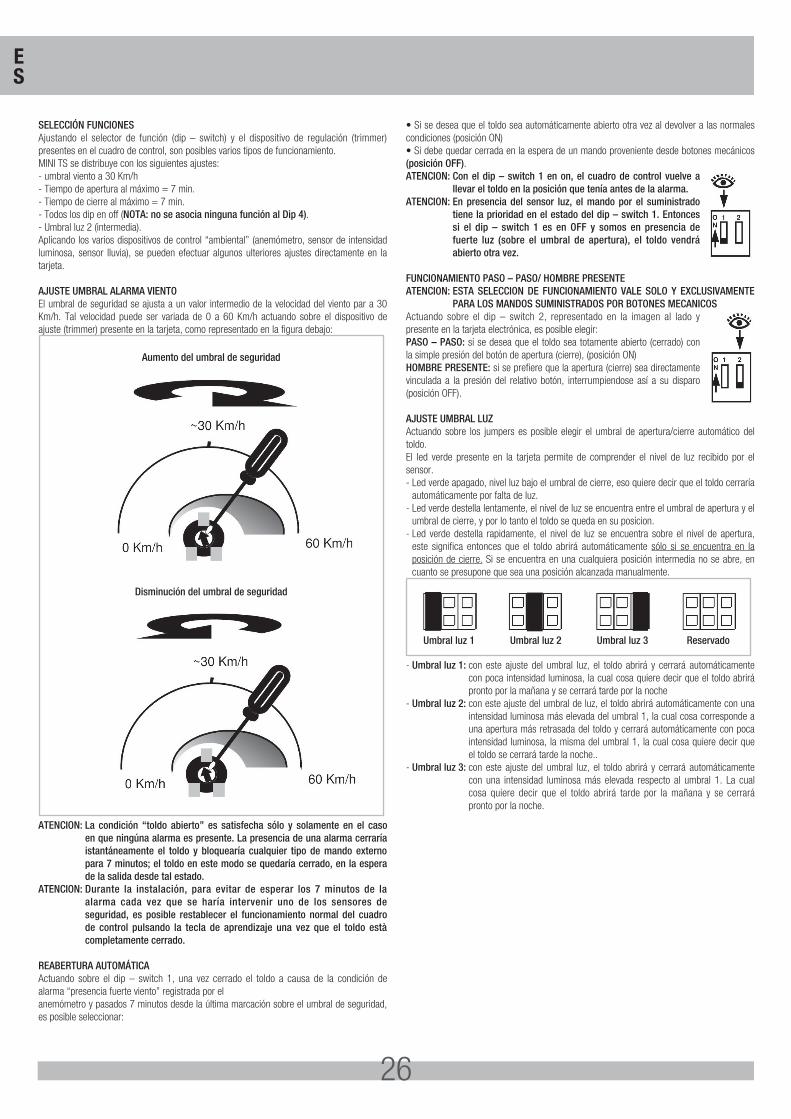
26
SELECCIÓN FUNCIONESAjustando el selector de función (dip – switch) y el dispositivo de regulación (trimmer) presentes en el cuadro de control, son posibles varios tipos de funcionamiento.MINI TS se distribuye con los siguientes ajustes:- umbral viento a 30 Km/h- Tiempo de apertura al máximo = 7 min.- Tiempo de cierre al máximo = 7 min.- Todos los dip en off (NOTA: no se asocia ninguna función al Dip 4).- Umbral luz 2 (intermedia).Aplicando los varios dispositivos de control “ambiental” (anemómetro, sensor de intensidad luminosa, sensor lluvia), se pueden efectuar algunos ulteriores ajustes directamente en la tarjeta.
AJUSTE UMBRAL ALARMA VIENTOEl umbral de seguridad se ajusta a un valor intermedio de la velocidad del viento par a 30 Km/h. Tal velocidad puede ser variada de 0 a 60 Km/h actuando sobre el dispositivo de ajuste (trimmer) presente en la tarjeta, como representado en la figura debajo:
Aumento del umbral de seguridad
Disminución del umbral de seguridad
ATENCION: La condición “toldo abierto” es satisfecha sólo y solamente en el caso en que ningúna alarma es presente. La presencia de una alarma cerraría istantáneamente el toldo y bloquearía cualquier tipo de mando externo para 7 minutos; el toldo en este modo se quedaría cerrado, en la espera de la salida desde tal estado.
ATENCION: Durante la instalación, para evitar de esperar los 7 minutos de la alarma cada vez que se haría intervenir uno de los sensores de seguridad, es posible restablecer el funcionamiento normal del cuadro de control pulsando la tecla de aprendizaje una vez que el toldo està completamente cerrado.
REABERTURA AUTOMÁTICAActuando sobre el dip – switch 1, una vez cerrado el toldo a causa de la condición de alarma “presencia fuerte viento” registrada por elanemómetro y pasados 7 minutos desde la última marcación sobre el umbral de seguridad, es posible seleccionar:
• Si se desea que el toldo sea automáticamente abierto otra vez al devolver a las normales condiciones (posición ON)• Si debe quedar cerrada en la espera de un mando proveniente desde botones mecánicos (posición OFF).ATENCION: Con el dip – switch 1 en on, el cuadro de control vuelve a
llevar el toldo en la posición que tenía antes de la alarma.ATENCION: En presencia del sensor luz, el mando por el suministrado
tiene la prioridad en el estado del dip – switch 1. Entonces si el dip – switch 1 es en OFF y somos en presencia de fuerte luz (sobre el umbral de apertura), el toldo vendrá abierto otra vez.
FUNCIONAMIENTO PASO – PASO/ HOMBRE PRESENTEATENCION: ESTA SELECCION DE FUNCIONAMIENTO VALE SOLO Y EXCLUSIVAMENTE
PARA LOS MANDOS SUMINISTRADOS POR BOTONES MECANICOSActuando sobre el dip – switch 2, representado en la imagen al lado y presente en la tarjeta electrónica, es posible elegir:PASO – PASO: si se desea que el toldo sea totamente abierto (cerrado) con la simple presión del botón de apertura (cierre), (posición ON)HOMBRE PRESENTE: si se prefiere que la apertura (cierre) sea directamente vinculada a la presión del relativo botón, interrumpiendose así a su disparo (posición OFF).
AJUSTE UMBRAL LUZActuando sobre los jumpers es posible elegir el umbral de apertura/cierre automático del toldo. El led verde presente en la tarjeta permite de comprender el nivel de luz recibido por el sensor.- Led verde apagado, nivel luz bajo el umbral de cierre, eso quiere decir que el toldo cerraría
automáticamente por falta de luz. - Led verde destella lentamente, el nivel de luz se encuentra entre el umbral de apertura y el
umbral de cierre, y por lo tanto el toldo se queda en su posicion. - Led verde destella rapidamente, el nivel de luz se encuentra sobre el nivel de apertura,
este significa entonces que el toldo abrirá automáticamente sólo si se encuentra en la posición de cierre. Si se encuentra en una cualquiera posición intermedia no se abre, en cuanto se presupone que sea una posición alcanzada manualmente.
Umbral luz 1 Umbral luz 2 Umbral luz 3 Reservado
- Umbral luz 1: con este ajuste del umbral luz, el toldo abrirá y cerrará automáticamente con poca intensidad luminosa, la cual cosa quiere decir que el toldo abrirá pronto por la mañana y se cerrará tarde por la noche
- Umbral luz 2: con este ajuste del umbral de luz, el toldo abrirá automáticamente con una intensidad luminosa más elevada del umbral 1, la cual cosa corresponde a una apertura más retrasada del toldo y cerrará automáticamente con poca intensidad luminosa, la misma del umbral 1, la cual cosa quiere decir que el toldo se cerrará tarde la noche..
- Umbral luz 3: con este ajuste del umbral luz, el toldo abrirá y cerrará automáticamente con una intensidad luminosa más elevada respecto al umbral 1. La cual cosa quiere decir que el toldo abrirá tarde por la mañana y se cerrará pronto por la noche.
ES
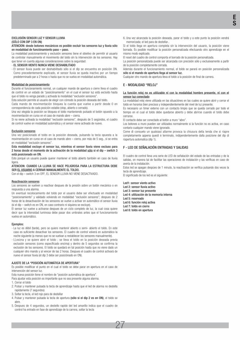
27
EXCLUSIÓN SENSOR LUZ Y SENSOR LLUVIA (SÓLO CON DIP 3 EN ON)ATENCION: desde botones mecánicos es posible excluír los sensores luz y lluvia sólo en modalidad de funciónamiento paso – paso.La modalidad posicionamiento y exclusión sensores tiene el obietivo de permitir al usuario de controlar manualmente el movimiento del toldo sín la intervención de los sensores. Hay que tener en cuenta algunas consideraciones sobre la seguridad:- EL SENSOR VIENTO NUNCA VIENE DESHABILITADO- El sensor lluvia puede ser deshabilitado sólo si el dip se encuentra en posición ON.
Como precedentemente explicado, el sensor lluvia se queda inactivo por un tiempo predeterminado par a 2 horas o hasta que no se vuelva en modalidad automática.
Modalidad de posicionamientoDurante el funcionamiento normal, un cualquier mando de apertura o cierre lleva el cuadro de control en un estado de “posiciónamiento” en el cual el sensor luz està excluído hasta que el toldo no venga parado y activada la modalidad “exclusión sensores”. Esta solución permite al usuario de elegir con cómodo la posición deseada del toldo. Cada mando de movimentación bloquea la cuenta que vuelve a partir desde 0 en correspondencia de cada posición estable (stop, abierto o cerrado). Una vez elegida la posición se bloquea el toldo manteniendo pulsado el botón opuesto a la movimentación en curso en el caso de mando abre – cierra. Si no viene activada la modalidad “exclusión sensores”, después de 5 segúndos, el cuadro de control vuelve en modalidad automática y el sensor viene activado de nuevo.
Exclusión sensoresUna vez posicionado el toldo en la posición deseada, pulsando la tecla opuesta a la movimentación en curso en el caso de mando abre – cierra, por más de 5 seg., si se entra en modalidad “exclusión sensores”.Esta modalidad excluye el sensor luz, mientras el sensor lluvia viene excluso para 2 horas desde el momento de la activación de la modalidad sólo si el dip – switch 3 està posicionado en ON.Esto porqué un usuario puede querer mantener el toldo abierto también en caso de lluvia ligera.ATENCION: CUANDO LA LLUVIA SE HACE PELIGROSA PARA LA ESTRUCTURA DEBE SER EL USUARIO A CERRAR MANUALMENTE EL TOLDO.Con el dip – switch 3 en OFF, EL SENSOR LLUVIA NO VIENE DESACTIVADO.
Reactivación sensoresLos sensores se vuelven a reactivar despues de la presión sobre un botón mecánico o en respuesta a una alarma. Un eventual recolocamiento del toldo por el usuario debe ser efectuado en modalidad “posicionamiento” y validado volviendo en modalidad “exclusión sensores”; despues de 2 horas de la desactivación de los sensores se vuelve a activar en automático el sensor lluvia (si el dip – switch es en ON, en caso contrario ni siquiera se excluye).El sensor luz vuelve a activarse despues de un ciclo completo de luz, la cual cosa quiere decir que la intensidad luminosa debe pasar dos umbrales antes que el funcionamiento vuelva en automático.
Ejemplos:- La luz es débil (tarde), pero se quiere mantenir abierto o semi- abierto el toldo. En este
caso es suficiente desactivar los sensores. El cuadro de control volverá en automático la noche siguiente (a menos que no se vuelvan a restablecer los sensores manualmente).
- LLovizna y se quiere abrir el toldo ; se lleva el toldo en la posición deseada previa exclusión sensores (como especificado encima) y dentro de 5 segundos se confirma la exclusión de los sensores. El toldo se quedará en tal posición hasta que no viene dado un cualquier otro mando y al vencer de las 2 horas. Despues el cuadro de control activará de nuevo el sensor lluvia (el dip 3 debe ser posiciónado en ON).
AJUSTE DE LA “POSICIÓN AUTOMÁTICA DE APERTURA”Es posible modificar el punto en el cual el toldo se debe parar en apertura en el caso de intervención del sensor luz. Esta nueva posición tiene el nombre de “posición automática de apertura”. Para ajustar esta posición es importante que no sea presente alguna alarma.1. Cerrar el toldo2. Pulsar y mantener pulsada la tecla de aprendizaje hasta que el led de alarma no destella
rapidamente (7 segundos)3. Soltar la tecla, el led rojo para de destellar4. Pulsar y mantener pulsada la tecla de apertura (sólo si el dip 2 es en ON), el toldo se
abre.5. Despues de 4 segundos, un destello rapido del led amarillo indica que el cuadro de
control ha entrado en fase de aprendizaje de la carrera, soltar la tecla
6. Una vez alcanzada la posición deseada, parar el toldo y a este punto la posición vendrá memorizada; el led para de destellar..
Si el toldo llega en apertura completa sín la intervención del usuario, la posición viene borrada. Es posible modificar la posición personalizada efectuando otro aprendizaje en el mismo modo explicado.El reset del cuadro de control comporta el borrado de la posición personalizada.La posición personalizada puede ser alcanzada con precisión sólo y exclusivamente a partir de la posición completamente cerrada. Además durante el funcionamiento normal, el toldo se parará en posición personalizada sólo si el mando de apertura llega al sensor luz.Cualquier otro mando de apertura lleva el toldo a la posición de final de carrera.
E - MODALIDAD “RELOJ”
La función reloj no es utilizable ní con la modalidad hombre presente, ní con el sensor luz conectadoLa modalidad reloj viene utilizada en las situaciónes en las cuales se quiere abrir y cerrar el toldo en horarios bien precisos y independientemente del nivel de luz presente. Es necesario un timer externo con un contacto limpio que se queda cerrado por todo el tiempo en el cual el toldo debe quedarse abierto y debe abrirse cuando el toldo debe cerrarse.El contacto debe ser conectado al botón a muro “abre”. Los botones a muro pueden ser utilizados normalmente si la función no es activa, en caso contario cualquier mando viene ignorado.Come di consueto un qualsiasi allarme provoca la chiusura della tenda che si riapre completamente appena questi è terminato, indipendentemente dalla posizione del dip di riapertura automatica (dip 1).
F - LED DE SEÑALACIÓN ENTRADAS Y SALIDAS
El cuadro de control lleva una serie de LED de señalación del estado de las entradas y de la salidas, en manera tal de facilitar las operaciones de instalación y las veríficas en caso de avería de la instalación. Estos led se apagan despúes de 1 minuto, la reactivación se verifica pulsando dos veces la tecla de aprendizaje. El significado de los led es el siguíente:
Led1: sensor viento activo Led 2: sensor lluvia activoLed 3: sensor luz presente Led 4: utilización de la memoria internaLed 5: reservadoLed 6: función reloj activaLed 7: toldo en cierreLed 8: toldo en apertura
ES
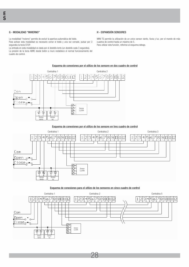
28
G - MODALIDAD “INVIERNO”
La modalidad “invierno” permite de excluír la apertura automática del toldo. Para activar esta modalidad es necesario cerrar el toldo y una vez cerrado, pulsar por 3 segundos la tecla STOP. La entrada en esta modalidad es dada por el destello lento (un destello cada 3 segundos).La presión de la tecla ABRE desde botón a muro restablece el normal funcionamiento del cuadro de control.
H - EXPANSIÓN SENSORES
MINI TS permite la utilización de un unico sensor viento, lluvia y luz, por el mando de más cuadros de control hasta un máximo de 5. Para utilizar esta función, referirse al esquema debajo.
Sensorviento
SensorLLUVIA
Sensorluz
Centralina 1 Centralina 2
Sensorviento
SensorLLUVIA
Sensorluz
Centralina 1 Centralina 2 Centralina 3
Sensorviento
SensorLLUVIA
Sensorluz
Centralina 1 Centralina 2 Centralina 5
Esquema de conexiones por el utilizo de los sensore en dos cuadro de control
Esquema de conexiones por el utilizo de los sensore en tres cuadro de control
Esquema de conexiones para el utilizo de los sensores en cinco cuadro de control
ES
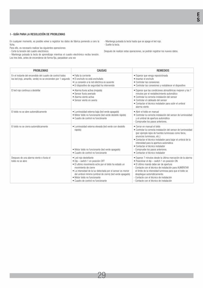
29
En cualquier momento, es posible volver a registrar los datos de fábrica poniendo a cero la ficha.Para ello, es necesario realizar las siguientes operaciones:- Corte la tensión del cuadro electrónico.- Mantenga pulsada la tecla de aprendizaje mientras el cuadro electrónico reciba tensión. Los tres leds, antes de encenderse de forma fija, parpadean una vez
- Mantenga pulsada la tecla hasta que se apage el led rojo.- Suelte la tecla. Después de realizar estas operaciones, se podrán registrar los nuevos datos.
PROBLEMAS CAUSAS REMEDIOS
En el instante del encendido del cuadro de control todos los led (rojo, amarillo, verde) no se encienden por 1 segundo
• Falta la corriente• El enchufe no está enchufado• La conexión a la red eléctrica es ausente• El dispositivo de seguridad ha intervenido
• Esperar que venga reposiciónada• Insertar el enchufe• Controlar las conexiones• Controlar las conexiones y restablecer el dispositivo
El led rojo continua a destellar • Alarma lluvia activa (mojada)• Sensor lluvia averiado• Alarma viento activa• Sensor viento en avería
• Esperar que las condiciones atmosféricas mejoren y los 7 minutos por el restablecimiento automático
• Controlar la correcta instalación del sensor• Controlar el cableado del sensor• Contactar el técnico instalador para subir el umbral
alarma viento
El toldo no se abre automáticamente • Luminosidad externa baja (led verde apagado)• Motor toldo no funcionante (led verde destello rápido)• Cuadro de control no funciónante
• Abrir el toldo en manual• Controlar la correcta instalación del sensor de luminosidad
y el umbral de apertura automática- Compruebe los pasos anteriores.
El toldo no se cierra automáticamente • Luminosidad externa elevada (led verde con destello rápido)
• Motor toldo no funcionante (led verde apagado)• Cuadro de control no funcionante
• Cerrar en manual el toldo• Controlar la correcta instalación del sensor de luminosidad
(por ejemplo lejos de fuentes luminosas como faros, anuncios luminosos, etc.)
• Contactar el técnico instalador para bajar el umbral de la intensidad para la apertura automática
• Contactar el técnico instalador- Compruebe los pasos anteriores.• Contactar el técnico instalador
Despues de una alarma viento o lluvia eltoldo no se abre
• Led rojo destellante• Dip – switch 1 en posición OFF• El ultimo movimiento echo por el toldo ha estado un
movimiento de cierre• La intensidad de la luz detectada por el sensor es menor
del umbral mínimo (umbral de cierre) (led verde apagado)• Motor toldo no funcionante• Cuadro de control no funcionante
• Esperar 7 minutos desde la última marcación de la alarma• Posiciónar el dip – switch 1 en posición ON• El último mando debe ser de apertura- Contacte con el técnico de instalación para AUMENTAR
el límite de la intensidad luminosa para que el toldo se despliegue automáticamente.
- Contacte con el técnico de instalación- Contacte con el técnico de instalación
I - GUÍA PARA LA RESOLUCIÓN DE PROBLEMAS
ES

30
NOTES

31
NOTES
Cod.
CVA
1524
- 2
9092
014
- Re
v. 0
6
MINI TS 2nd edition
Questo prodotto è stato completamente progettato e costruito in Italia · Ce produit a été complètement développé et fabriqué en Italie · This product has been completely developed and built in Italy · Artìculo totalmente proyectado y producido en Italia
25014 CASTENEDOLO (BS) - ITALY
Via Matteotti, 162
Tel. +39.030.2135811
Fax +39.030.21358279
www.ribind.it - [email protected] per cancelli
automatic entry systems
®