istruzioni di montaggio assembly instruction ...
20
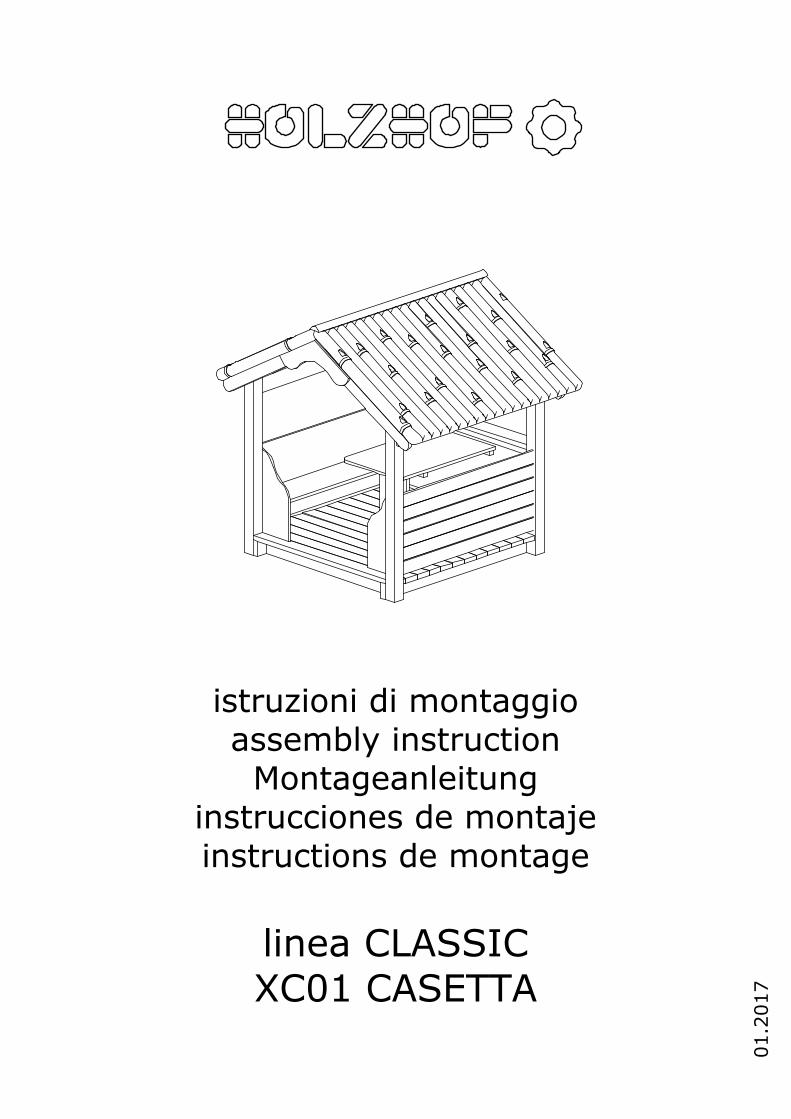
istruzioni di montaggio assembly instruction Montageanleitung instrucciones de montaje instructions de montage linea CLASSIC XC01 CASETTA 01.2017
Transcript of istruzioni di montaggio assembly instruction ...
istruzioni di montaggioassembly instructionMontageanleitung
instrucciones de montajeinstructions de montage
linea CLASSICXC01 CASETTA
01.2
017
08/04/15
Colori e modelli rappresentati sono puramente indicativi e potranno variare a nostra discrezione.
In fase di installazione si consiglia di fissare definitivamente la bulloneria ed inserire i tappi solo dopo aver verificato il corretto posizionamento degli elementi, parallelismi, verticalità e quant’altro.
Utilizzare gli strumenti di installazione in modo appropriato e seguire alla precisione quanto descritto nelle istruzioni. Le istruzioni sono realizzate per una posa in opera che segue le normative UNI EN 1176, in caso di installazione in maniera differente da quanto descritto si potrebbe andare incontro ad un montaggio non a norma.
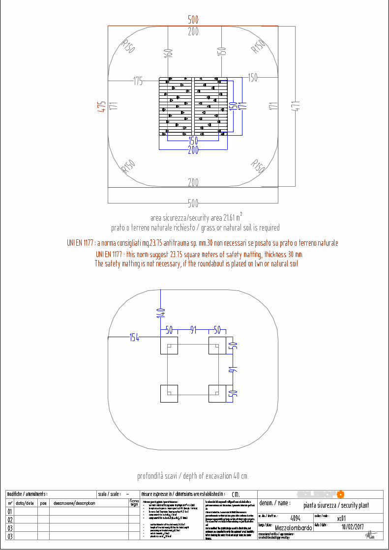
Gli scavi e la realizzazione dei plinti di fondazione DEVONO essere eseguiti come da illustrazioni, rispettando dimensioni e raggiature, come richiesto dalla norma UNI EN1176.
Utilizzare cemento minimo C20/25
Dove necessario segnare la posizione prima di forare con l’ apposita punta descritta.
I codici numerici 8xxxx si riferiscono al titolo ed al riferimento del particolare di montaggio.
La bollinatura nella pagina principale è da seguire come sequenza temporale di montaggio.
Le misure, salvo diversamente indicato, sono espresse in cm.
Prestare attenzione alla numerazione dei montanti; la numerazione corrispondente si trova sotto ogni montante.
Seguire l’orientamento delle assi e dei pianali rappresentato in figura.
Le misure della viteria, salvo indicazioni differenti, sono espresse in mm. e riportano i la tipologia di inserto da utilizzareTORX - ESAGONO - Pozidriv (vedere legenda simboli)
Le strutture in alluminio sono contrassegnate dalla dicitura AL; nelle pagine il simbolo AL significa che è necessario eseguire quel tipo di installazione SOLO per le strutture in alluminio.
E’ disponibile in allegato la corretta procedura per ancorare o interrare la struttura; sarà sufficiente seguire i passaggi relativi al tipo di soluzione richiesta in fase di ordine per fissare al suolo la staffa. La tipologia di staffa è indicata dall’ apposito simbolo (vedere legenda simboli).ma equivalente.
In alcune schede di montaggio potrebbe essere rappresentato un prodotto differente da quello ricevuto (ad esempio scivolo o pedane di risalita possono essere differenti in quanto adatte a diverse altezze); ad ogni modo il sistema di montaggio resta il medesimo.
Per ogni problema o dubbio vi invitiamo a contattare l’azienda (centralino +39.0461.601501 oppure [email protected]); un incaricato vi fornirà tutte le delucidazioni necessarie.
Per motivi di reale disponibilità a magazzino potrebbe essere fornita della viteria alternativa a quella specificamente indicata,
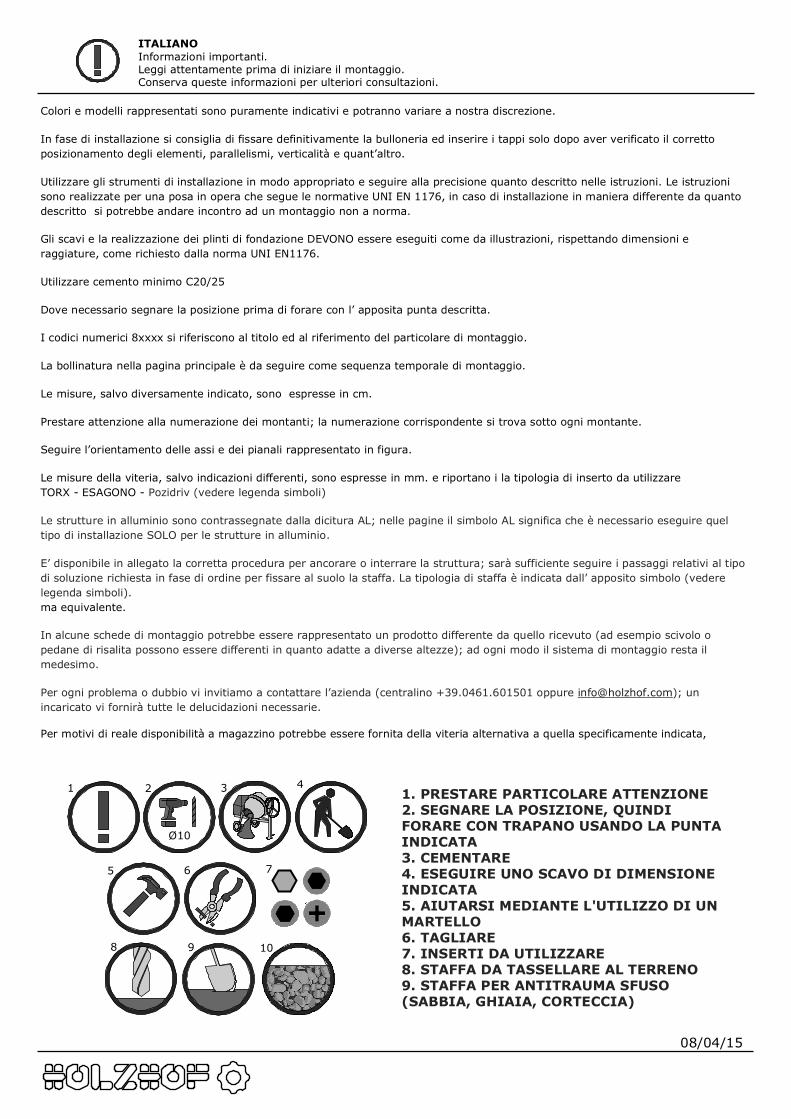
ITALIANOInformazioni importanti.Leggi attentamente prima di iniziare il montaggio.Conserva queste informazioni per ulteriori consultazioni.
1. PRESTARE PARTICOLARE ATTENZIONE2. SEGNARE LA POSIZIONE, QUINDI FORARE CON TRAPANO USANDO LA PUNTA INDICATA3. CEMENTARE4. ESEGUIRE UNO SCAVO DI DIMENSIONE INDICATA5. AIUTARSI MEDIANTE L'UTILIZZO DI UN MARTELLO6. TAGLIARE7. INSERTI DA UTILIZZARE8. STAFFA DA TASSELLARE AL TERRENO9. STAFFA PER ANTITRAUMA SFUSO (SABBIA, GHIAIA, CORTECCIA)10. STAFFA DA INTERRO
Ø10
1 2 3 4
5 6 7
8 9 10
08/04/15
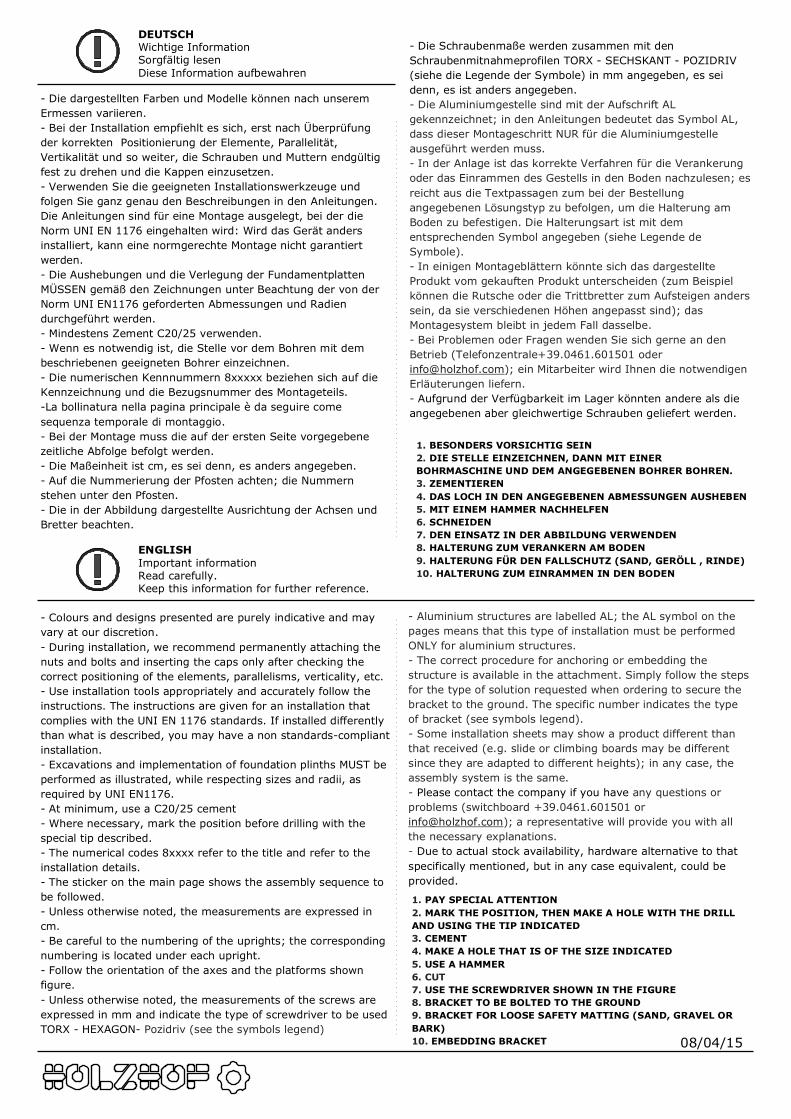
- Colours and designs presented are purely indicative and may vary at our discretion.- During installation, we recommend permanently attaching the nuts and bolts and inserting the caps only after checking the correct positioning of the elements, parallelisms, verticality, etc.- Use installation tools appropriately and accurately follow the instructions. The instructions are given for an installation that complies with the UNI EN 1176 standards. If installed differently than what is described, you may have a non standards-compliant installation. - Excavations and implementation of foundation plinths MUST be performed as illustrated, while respecting sizes and radii, as required by UNI EN1176.- At minimum, use a C20/25 cement- Where necessary, mark the position before drilling with the special tip described.- The numerical codes 8xxxx refer to the title and refer to the installation details.- The sticker on the main page shows the assembly sequence to be followed.- Unless otherwise noted, the measurements are expressed in cm.- Be careful to the numbering of the uprights; the corresponding numbering is located under each upright.- Follow the orientation of the axes and the platforms shown figure.- Unless otherwise noted, the measurements of the screws are expressed in mm and indicate the type of screwdriver to be usedTORX - HEXAGON- Pozidriv (see the symbols legend)
ENGLISHImportant informationRead carefully.Keep this information for further reference.
1. PAY SPECIAL ATTENTION2. MARK THE POSITION, THEN MAKE A HOLE WITH THE DRILL AND USING THE TIP INDICATED3. CEMENT4. MAKE A HOLE THAT IS OF THE SIZE INDICATED5. USE A HAMMER6. CUT7. USE THE SCREWDRIVER SHOWN IN THE FIGURE8. BRACKET TO BE BOLTED TO THE GROUND9. BRACKET FOR LOOSE SAFETY MATTING (SAND, GRAVEL OR BARK)10. EMBEDDING BRACKET
- Aluminium structures are labelled AL; the AL symbol on the pages means that this type of installation must be performed ONLY for aluminium structures.- The correct procedure for anchoring or embedding the structure is available in the attachment. Simply follow the steps for the type of solution requested when ordering to secure the bracket to the ground. The specific number indicates the type of bracket (see symbols legend).- Some installation sheets may show a product different than that received (e.g. slide or climbing boards may be different since they are adapted to different heights); in any case, the assembly system is the same.- Please contact the company if you have any questions or problems (switchboard +39.0461.601501 or [email protected]); a representative will provide you with all the necessary explanations.- Due to actual stock availability, hardware alternative to that specifically mentioned, but in any case equivalent, could be provided.
DEUTSCHWichtige InformationSorgfältig lesenDiese Information aufbewahren
- Die dargestellten Farben und Modelle können nach unserem Ermessen variieren.- Bei der Installation empfiehlt es sich, erst nach Überprüfung der korrekten Positionierung der Elemente, Parallelität, Vertikalität und so weiter, die Schrauben und Muttern endgültig fest zu drehen und die Kappen einzusetzen.- Verwenden Sie die geeigneten Installationswerkzeuge und folgen Sie ganz genau den Beschreibungen in den Anleitungen. Die Anleitungen sind für eine Montage ausgelegt, bei der die Norm UNI EN 1176 eingehalten wird: Wird das Gerät anders installiert, kann eine normgerechte Montage nicht garantiert werden.- Die Aushebungen und die Verlegung der Fundamentplatten MÜSSEN gemäß den Zeichnungen unter Beachtung der von der Norm UNI EN1176 geforderten Abmessungen und Radien durchgeführt werden. - Mindestens Zement C20/25 verwenden.- Wenn es notwendig ist, die Stelle vor dem Bohren mit dem beschriebenen geeigneten Bohrer einzeichnen.- Die numerischen Kennnummern 8xxxxx beziehen sich auf die Kennzeichnung und die Bezugsnummer des Montageteils.-La bollinatura nella pagina principale è da seguire come sequenza temporale di montaggio.- Bei der Montage muss die auf der ersten Seite vorgegebene zeitliche Abfolge befolgt werden. - Die Maßeinheit ist cm, es sei denn, es anders angegeben.- Auf die Nummerierung der Pfosten achten; die Nummern stehen unter den Pfosten.- Die in der Abbildung dargestellte Ausrichtung der Achsen und Bretter beachten.
1. BESONDERS VORSICHTIG SEIN2. DIE STELLE EINZEICHNEN, DANN MIT EINER BOHRMASCHINE UND DEM ANGEGEBENEN BOHRER BOHREN.3. ZEMENTIEREN4. DAS LOCH IN DEN ANGEGEBENEN ABMESSUNGEN AUSHEBEN5. MIT EINEM HAMMER NACHHELFEN6. SCHNEIDEN7. DEN EINSATZ IN DER ABBILDUNG VERWENDEN8. HALTERUNG ZUM VERANKERN AM BODEN9. HALTERUNG FÜR DEN FALLSCHUTZ (SAND, GERÖLL , RINDE)10. HALTERUNG ZUM EINRAMMEN IN DEN BODEN
- Die Schraubenmaße werden zusammen mit den Schraubenmitnahmeprofilen TORX - SECHSKANT - POZIDRIV (siehe die Legende der Symbole) in mm angegeben, es sei denn, es ist anders angegeben.- Die Aluminiumgestelle sind mit der Aufschrift AL gekennzeichnet; in den Anleitungen bedeutet das Symbol AL, dass dieser Montageschritt NUR für die Aluminiumgestelle ausgeführt werden muss.- In der Anlage ist das korrekte Verfahren für die Verankerung oder das Einrammen des Gestells in den Boden nachzulesen; es reicht aus die Textpassagen zum bei der Bestellung angegebenen Lösungstyp zu befolgen, um die Halterung am Boden zu befestigen. Die Halterungsart ist mit dem entsprechenden Symbol angegeben (siehe Legende de Symbole).- In einigen Montageblättern könnte sich das dargestellte Produkt vom gekauften Produkt unterscheiden (zum Beispiel können die Rutsche oder die Trittbretter zum Aufsteigen anders sein, da sie verschiedenen Höhen angepasst sind); das Montagesystem bleibt in jedem Fall dasselbe.- Bei Problemen oder Fragen wenden Sie sich gerne an den Betrieb (Telefonzentrale+39.0461.601501 oder [email protected]); ein Mitarbeiter wird Ihnen die notwendigen Erläuterungen liefern.- Aufgrund der Verfügbarkeit im Lager könnten andere als die angegebenen aber gleichwertige Schrauben geliefert werden.
08/04/15
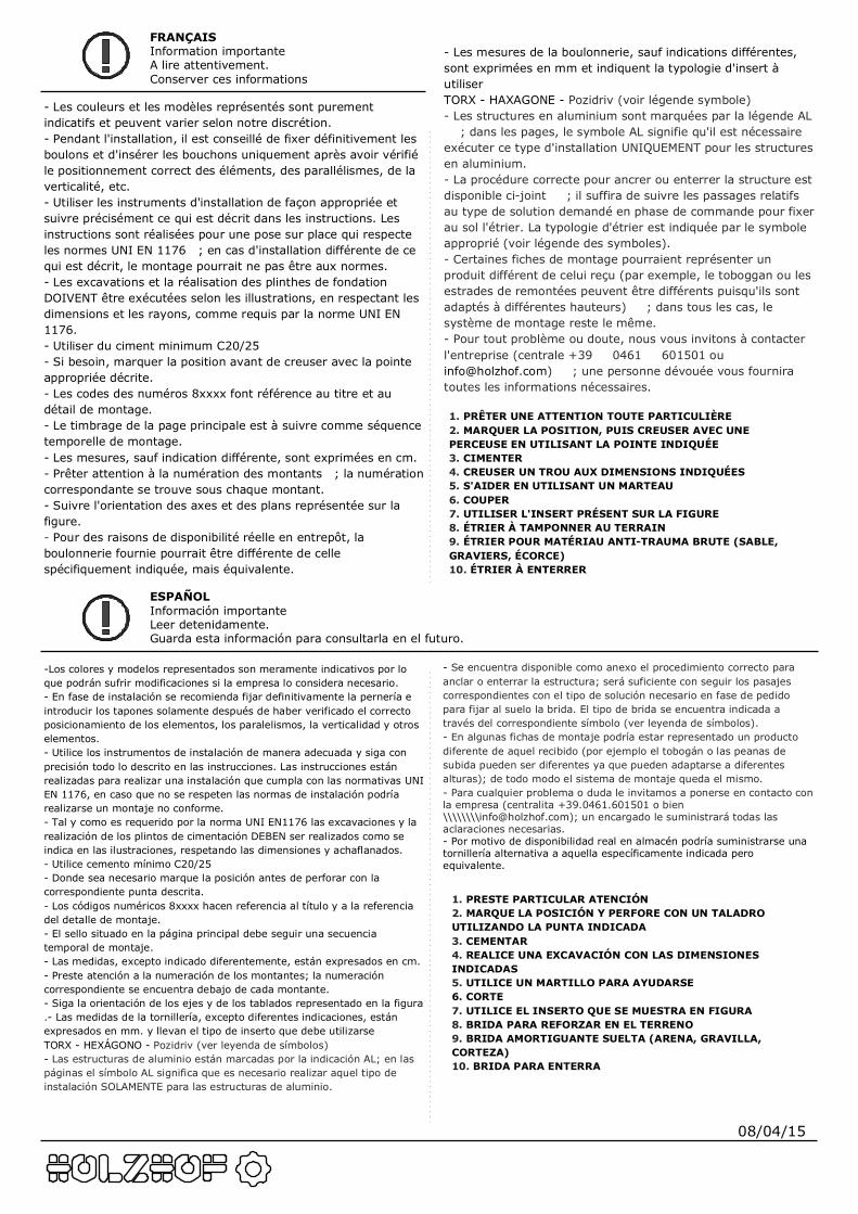
-Los colores y modelos representados son meramente indicativos por lo que podrán sufrir modificaciones si la empresa lo considera necesario.- En fase de instalación se recomienda fijar definitivamente la pernería e introducir los tapones solamente después de haber verificado el correcto posicionamiento de los elementos, los paralelismos, la verticalidad y otros elementos.- Utilice los instrumentos de instalación de manera adecuada y siga con precisión todo lo descrito en las instrucciones. Las instrucciones están realizadas para realizar una instalación que cumpla con las normativas UNI EN 1176, en caso que no se respeten las normas de instalación podría realizarse un montaje no conforme. - Tal y como es requerido por la norma UNI EN1176 las excavaciones y la realización de los plintos de cimentación DEBEN ser realizados como se indica en las ilustraciones, respetando las dimensiones y achaflanados.- Utilice cemento mínimo C20/25- Donde sea necesario marque la posición antes de perforar con la correspondiente punta descrita.- Los códigos numéricos 8xxxx hacen referencia al título y a la referencia del detalle de montaje.- El sello situado en la página principal debe seguir una secuencia temporal de montaje.- Las medidas, excepto indicado diferentemente, están expresados en cm.- Preste atención a la numeración de los montantes; la numeración correspondiente se encuentra debajo de cada montante.- Siga la orientación de los ejes y de los tablados representado en la figura.- Las medidas de la tornillería, excepto diferentes indicaciones, están expresados en mm. y llevan el tipo de inserto que debe utilizarseTORX - HEXÁGONO - Pozidriv (ver leyenda de símbolos)- Las estructuras de aluminio están marcadas por la indicación AL; en las páginas el símbolo AL significa que es necesario realizar aquel tipo de instalación SOLAMENTE para las estructuras de aluminio.
ESPAÑOLInformación importanteLeer detenidamente.Guarda esta información para consultarla en el futuro.
1. PRESTE PARTICULAR ATENCIÓN2. MARQUE LA POSICIÓN Y PERFORE CON UN TALADRO UTILIZANDO LA PUNTA INDICADA3. CEMENTAR4. REALICE UNA EXCAVACIÓN CON LAS DIMENSIONES INDICADAS5. UTILICE UN MARTILLO PARA AYUDARSE6. CORTE7. UTILICE EL INSERTO QUE SE MUESTRA EN FIGURA8. BRIDA PARA REFORZAR EN EL TERRENO9. BRIDA AMORTIGUANTE SUELTA (ARENA, GRAVILLA, CORTEZA)10. BRIDA PARA ENTERRA
- Se encuentra disponible como anexo el procedimiento correcto para anclar o enterrar la estructura; será suficiente con seguir los pasajes correspondientes con el tipo de solución necesario en fase de pedido para fijar al suelo la brida. El tipo de brida se encuentra indicada a través del correspondiente símbolo (ver leyenda de símbolos).- En algunas fichas de montaje podría estar representado un producto diferente de aquel recibido (por ejemplo el tobogán o las peanas de subida pueden ser diferentes ya que pueden adaptarse a diferentes alturas); de todo modo el sistema de montaje queda el mismo.- Para cualquier problema o duda le invitamos a ponerse en contacto con la empresa (centralita +39.0461.601501 o bien \\\\\\\\[email protected]); un encargado le suministrará todas las aclaraciones necesarias.- Por motivo de disponibilidad real en almacén podría suministrarse una tornillería alternativa a aquella específicamente indicada pero equivalente.
FRANÇAISInformation importanteA lire attentivement.Conserver ces informations
- Les couleurs et les modèles représentés sont purement indicatifs et peuvent varier selon notre discrétion.- Pendant l'installation, il est conseillé de fixer définitivement les boulons et d'insérer les bouchons uniquement après avoir vérifié le positionnement correct des éléments, des parallélismes, de la verticalité, etc.- Utiliser les instruments d'installation de façon appropriée et suivre précisément ce qui est décrit dans les instructions. Les instructions sont réalisées pour une pose sur place qui respecte les normes UNI EN 1176 ; en cas d'installation différente de ce qui est décrit, le montage pourrait ne pas être aux normes. - Les excavations et la réalisation des plinthes de fondation DOIVENT être exécutées selon les illustrations, en respectant les dimensions et les rayons, comme requis par la norme UNI EN 1176.- Utiliser du ciment minimum C20/25- Si besoin, marquer la position avant de creuser avec la pointe appropriée décrite.- Les codes des numéros 8xxxx font référence au titre et au détail de montage.- Le timbrage de la page principale est à suivre comme séquence temporelle de montage.- Les mesures, sauf indication différente, sont exprimées en cm.- Prêter attention à la numération des montants ; la numération correspondante se trouve sous chaque montant.- Suivre l'orientation des axes et des plans représentée sur la figure.- Pour des raisons de disponibilité réelle en entrepôt, la boulonnerie fournie pourrait être différente de celle spécifiquement indiquée, mais équivalente.
1. PRÊTER UNE ATTENTION TOUTE PARTICULIÈRE2. MARQUER LA POSITION, PUIS CREUSER AVEC UNE PERCEUSE EN UTILISANT LA POINTE INDIQUÉE3. CIMENTER4. CREUSER UN TROU AUX DIMENSIONS INDIQUÉES5. S'AIDER EN UTILISANT UN MARTEAU6. COUPER7. UTILISER L'INSERT PRÉSENT SUR LA FIGURE8. ÉTRIER À TAMPONNER AU TERRAIN9. ÉTRIER POUR MATÉRIAU ANTI-TRAUMA BRUTE (SABLE, GRAVIERS, ÉCORCE)10. ÉTRIER À ENTERRER
- Les mesures de la boulonnerie, sauf indications différentes, sont exprimées en mm et indiquent la typologie d'insert à utiliserTORX - HAXAGONE - Pozidriv (voir légende symbole)- Les structures en aluminium sont marquées par la légende AL ; dans les pages, le symbole AL signifie qu'il est nécessaire exécuter ce type d'installation UNIQUEMENT pour les structures en aluminium.- La procédure correcte pour ancrer ou enterrer la structure est disponible ci-joint ; il suffira de suivre les passages relatifs au type de solution demandé en phase de commande pour fixer au sol l'étrier. La typologie d'étrier est indiquée par le symbole approprié (voir légende des symboles).- Certaines fiches de montage pourraient représenter un produit différent de celui reçu (par exemple, le toboggan ou les estrades de remontées peuvent être différents puisqu'ils sont adaptés à différentes hauteurs) ; dans tous les cas, le système de montage reste le même.- Pour tout problème ou doute, nous vous invitons à contacter l'entreprise (centrale +39 0461 601501 ou [email protected]) ; une personne dévouée vous fournira toutes les informations nécessaires.
’
’
• • • • •
• • • • •
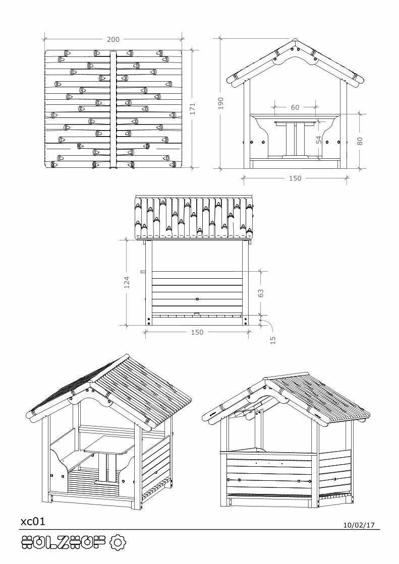
xc01 10/02/17
171
200
190
80
63
15
150
150
54
60
124
xc01 10/02/17
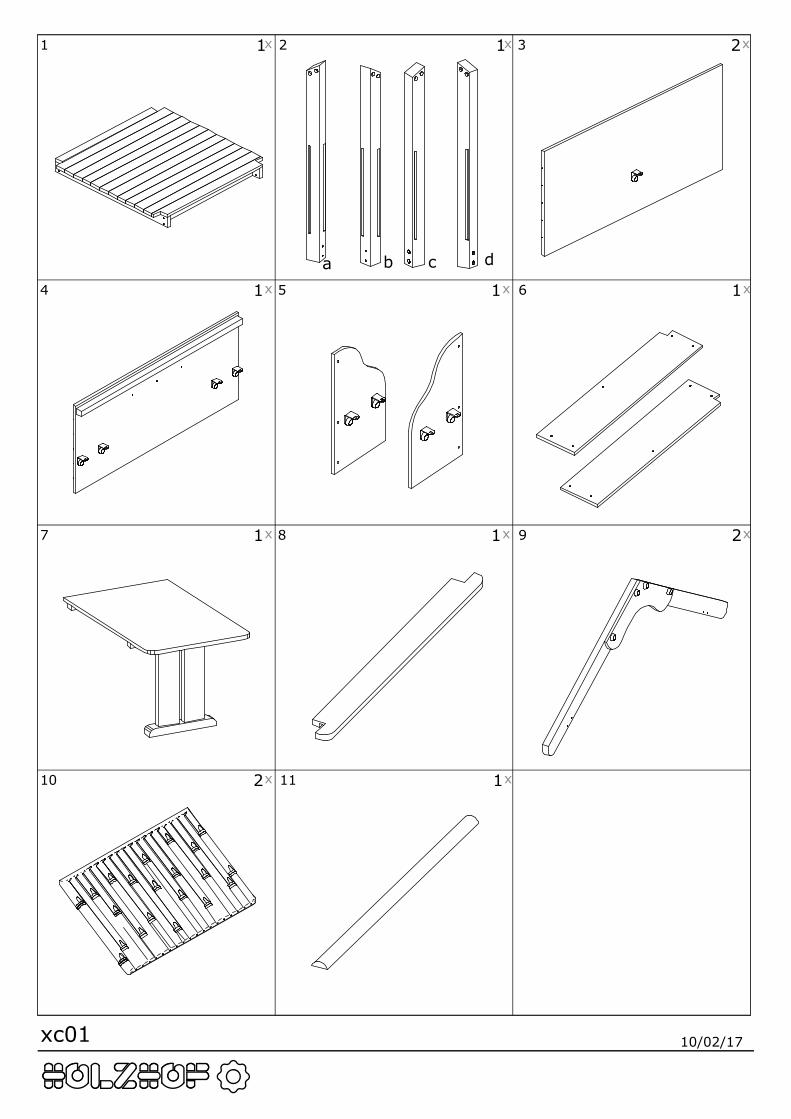
1 x1 2 x1 3 2x
4 1x 5 1x 6 1x
7 1x 8 1x 9 2x
10 2x 11 1x
a b c d
xc01 10/02/17
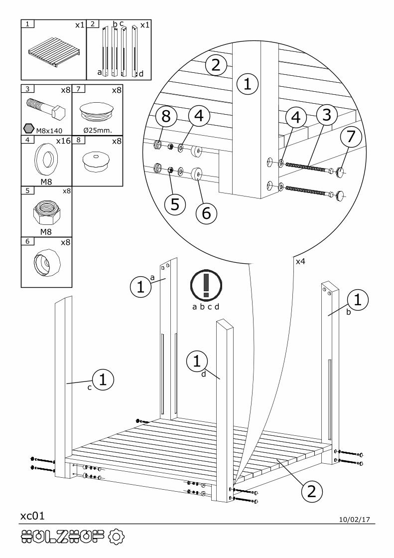
7 x8
Ø25mm.
5 x8
M8
3 x8
M8x1404 x16
M8
6 x8
8 x8
1 x1 2 x1
a
b c
d
a
b
cd
a b c d
12
38 47
5
4
6
2
1
1
1
1
x4

xc01 10/02/17
x11 x22
x12
3 x12
4x50
12
2
3
a
bc
d
xc01 10/02/17
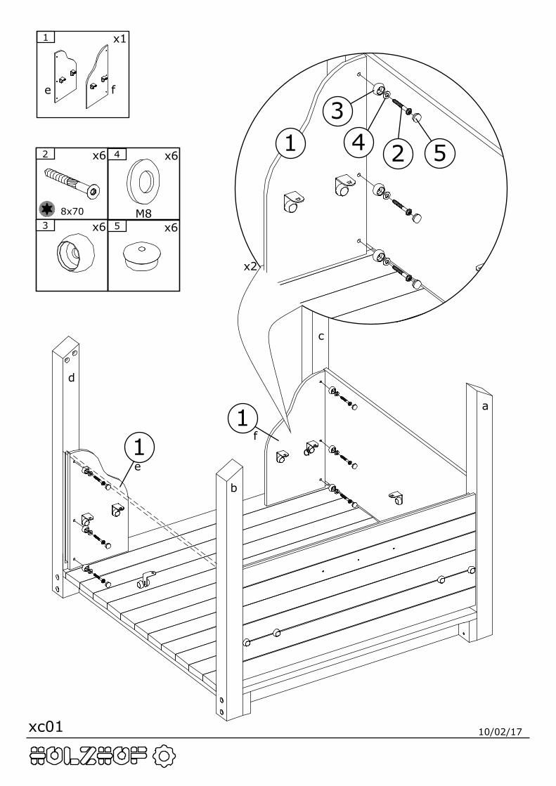
x11
e f
f
e
c
d
d
2 x6
8x703 x6 5 x6
4 x6
M8
1 2
34 5
11
x2
a
b
xc01 10/02/17
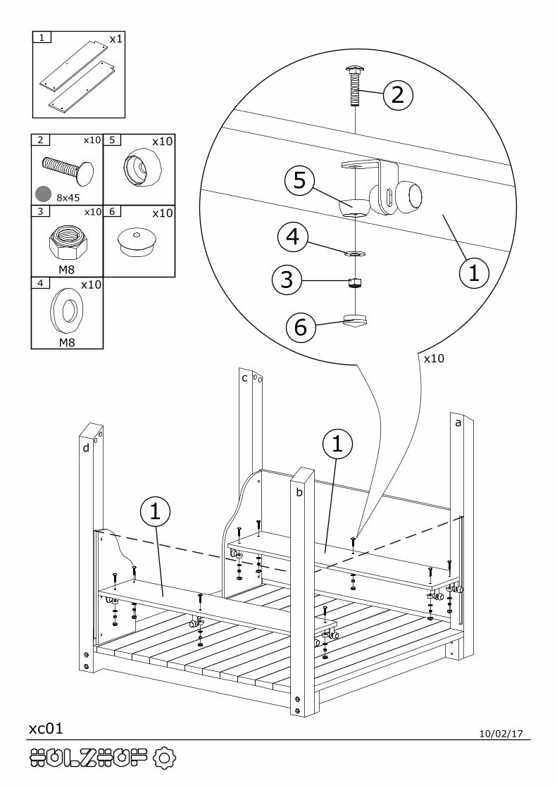
x11
x10
3 x10
M84 x10
M8
5 x10
6 x10
2 x10
8x45
2
3
4
5
6
1
1
1
c
d
a
b
xc01 10/02/17
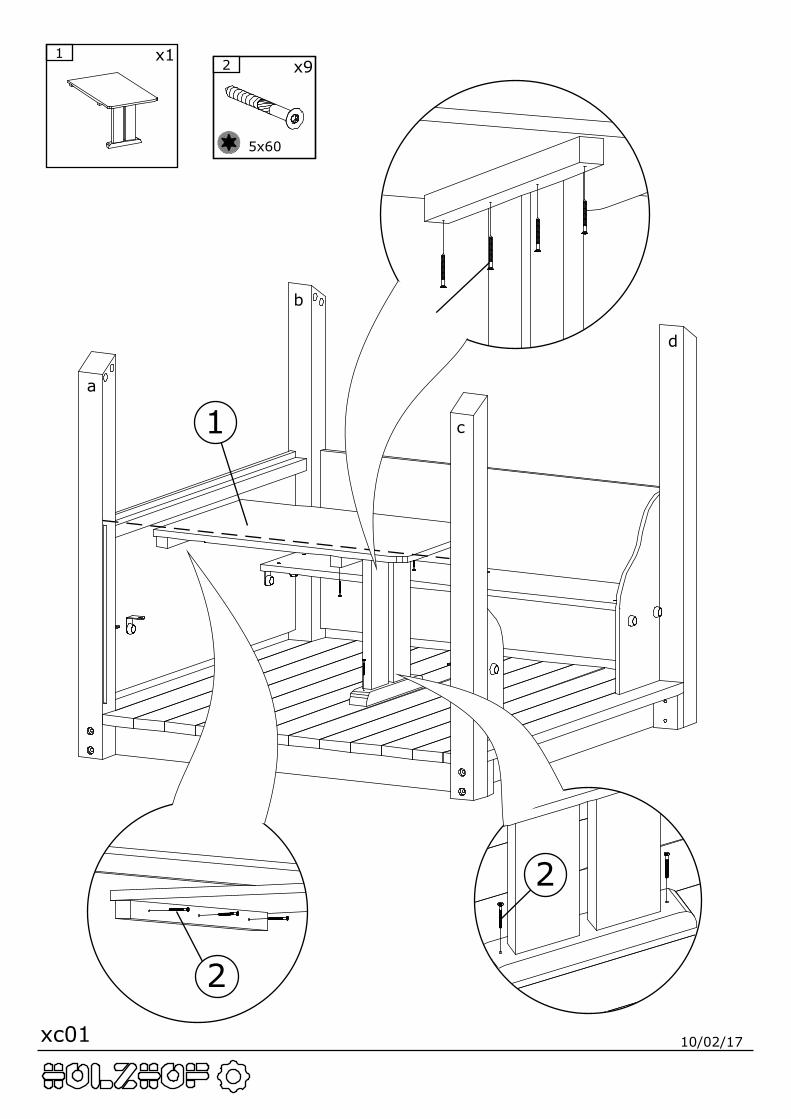
x112 x9
5x60
1
2
2
2
c
d
a
b
xc01 10/02/17
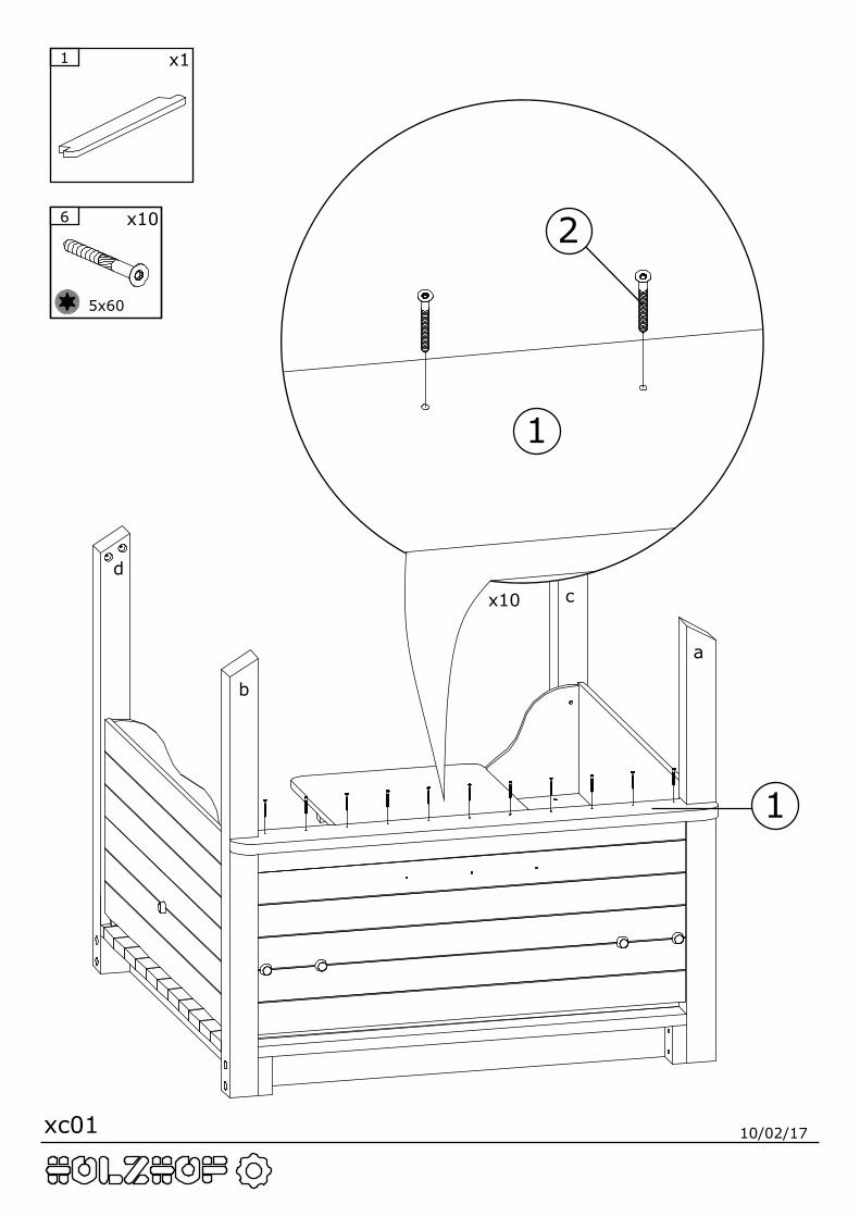
x11
x10
1
1
26 x10
5x60
cd
a
b
xc01 10/02/17
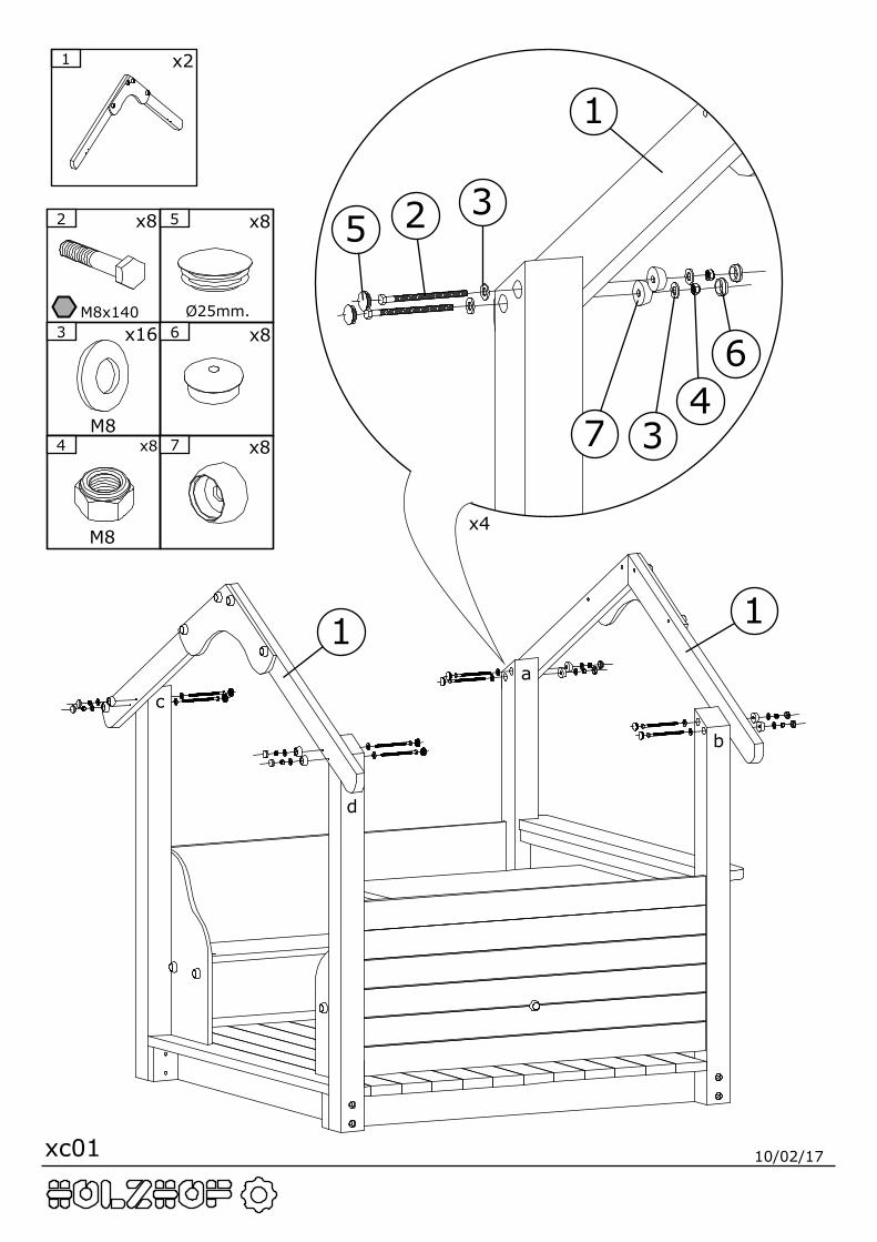
x21
5 x8
Ø25mm.
4 x8
M8
2 x8
M8x1403 x16
M87 x8
6 x8
1
11
2 3
34
5
6
7
c
d
a
b
x4
xc01 10/02/17
x21
4 x8
M8
5 x16
6 x16
2 x8
M8x753 x16
M8
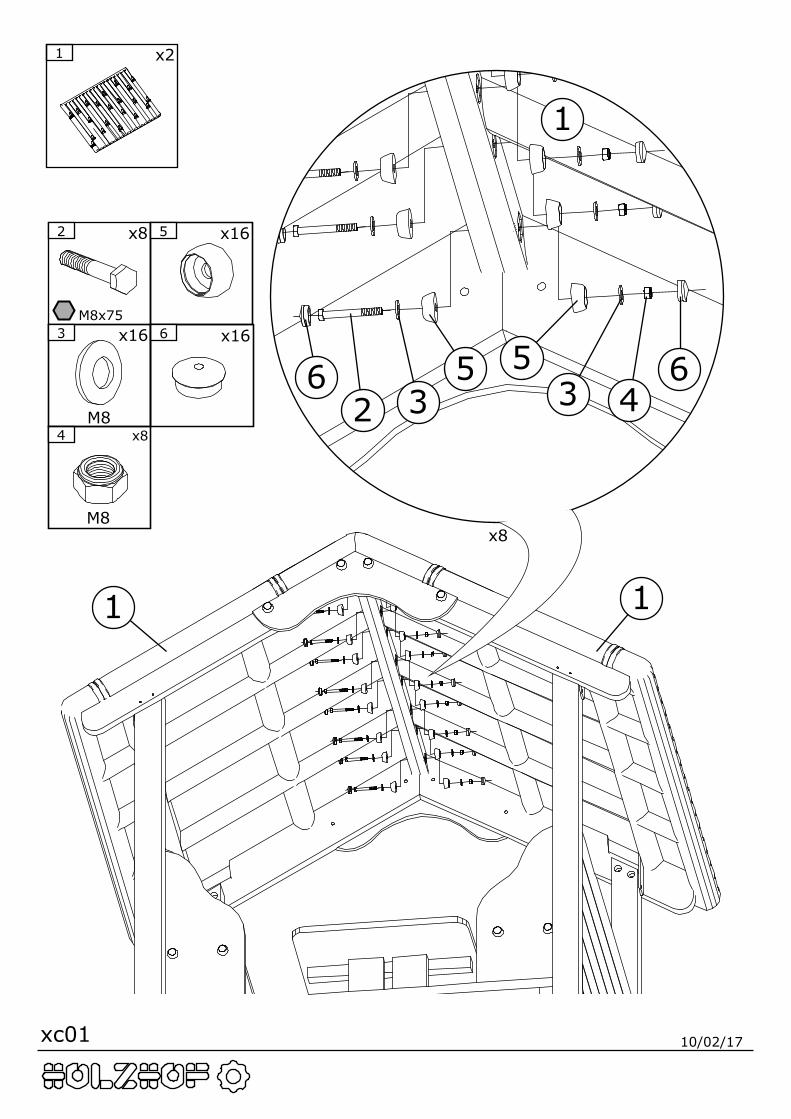
x8
1
11
2 3 3 45 56 6
xc01 10/02/17
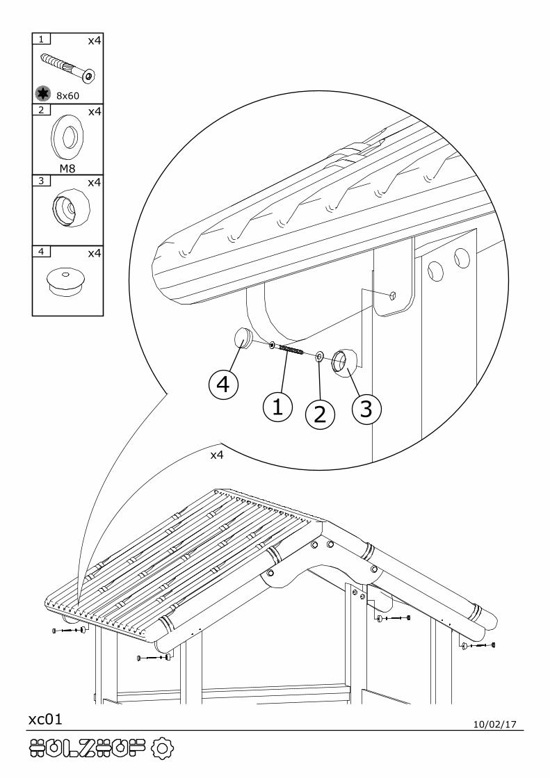
x4
1 x4
8x60
3 x4
4 x4
2 x4
M8
1 2 34
xc01 10/02/17
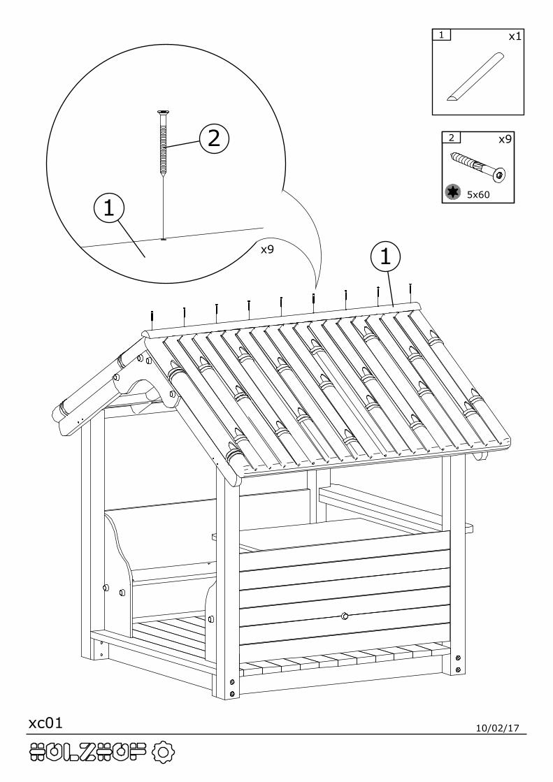
x9
1
1
2
x11
2 x9
5x60
xc01 10/02/17
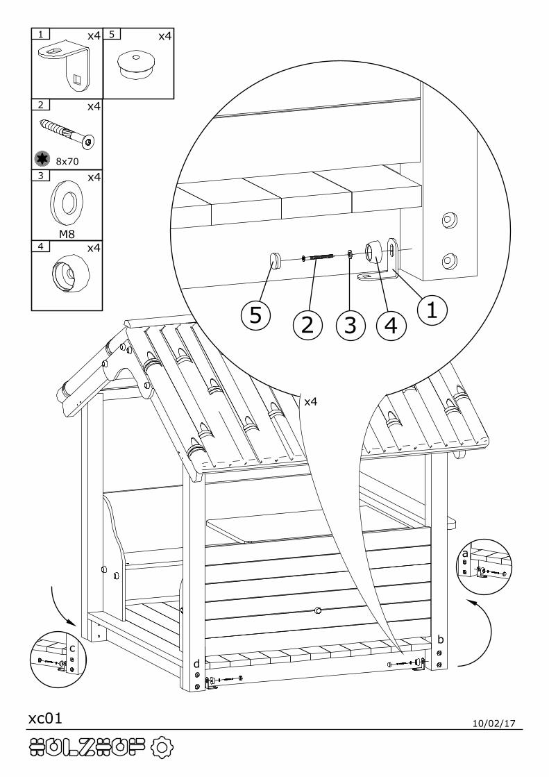
x4
1 x4
2 x4
8x703 x4
M84 x4
5 x4
12 3 45
d
b
a
c
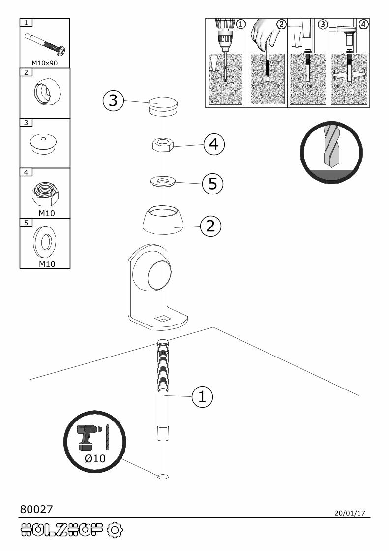
80027 20/01/17
2
1
M10x90
5
M10
3
4
M10
1
2
3
4
5
Ø10
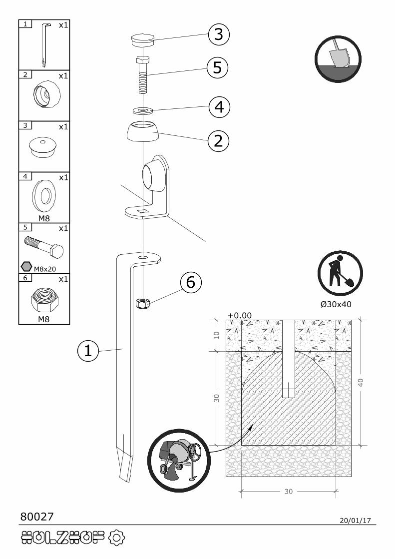
80027 20/01/17
+0.00
3010
40
Ø30x40
30
2 x1
3 x1
4 x1
M85 x1
M8x20
1 x1
1
2
3
4
5
66
M8
x1