filoparete a battente Istruzioni di montaggio - ep-porte - Filoparete Muratura... · Istruzioni di...
8
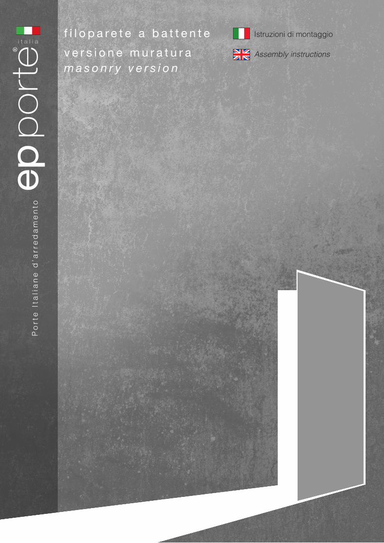
Istruzioni di montaggio Assembly instructions Porte Italiane d’arredamento filoparete a battente versione muratura masonry version
-
Upload
nguyentram -
Category
Documents
-
view
219 -
download
0
Transcript of filoparete a battente Istruzioni di montaggio - ep-porte - Filoparete Muratura... · Istruzioni di...
Istruzioni di montaggio
Assembly instructions
Po
rte
Ita
lia
ne
d’a
rre
da
me
nto
f i l o p a r e t e a b a t t e n t e
v e r s i o n e m u r a t u r am a s o n r y v e r s i o n
100 cm
100 cm
RUSTICO
A
1
2
3
1
2
3
4
5 PAVIMENTO FINITOFINISHED FLOOR
PAVIMENTO FINITOFINISHED FLOOR
RUSTICO / RUSTIC
RUSTICO / RUSTIC
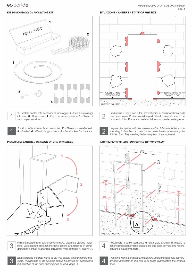
1 - Scatola contenente accessori di montaggio. 2 - Garza o rete reggi intonaco. 3 - Guarnizione. 4 - Copri cerniera in plastica. 5 - Chiave di servizio per serratura.
Prima di posizionare il telaio nel vano muro, piegare le zanche metal-liche. La piegatura delle zanche deve essere fatta tenendo in consi-derazione il senso di apertura della porta (vedi dettaglio A, pagina 2).
Predisporre il vano con i fori architettonici in corrispondenza delle zanche a murare. Posizionare i due piedi di livello come riferimento del pavimento finito. Preparare i testimoni di intonaco sulla parete grezza.
Posizionare il telaio (completo di distanziali, angolari di metallo e zanche precedentemente piegate) sui due piedi di livello che rappre-sentano il pavimento finito.
versione MURATURA / MASONRY versionpag. 1
KIT DI MONTAGGIO / MOUNTING KIT
PIEGATURA ZANCHE / BENDING OF THE BRACKETS
SITUAZIONE CANTIERE / STATE OF THE SITE
INSERIMENTO TELAIO / INSERTION OF THE FRAME
Prepare the space with the presence of architectural holes corre-sponding to brackets. Locate the two level bases representing the finished floor. Prepare the plaster sample on the rough wall.
Place the frame (complete with spacers, metal triangles and previou-sly bent brackets) on the two level bases representing the finished floor.
1 - Box with assembly accessories. 2 - Gauze or plaster net. 3 - Gasket. 4 - Plastic hinge covers. 5 - Service key for the lock.
Before placing the door frame in the wall space, bend the metal bra-ckets. The bending of the brackets should be carried out considering the direction of the door opening (see detail A, page 2).
1 2
43
1
3
2
4
B
C5A1
A A
100 cm
VISTA ESTERNA / EXTERNAL VIEW VISTA ESTERNA / EXTERNAL VIEW
RUSTICO / RUSTIC
PAVIMENTO FINITOFINISHED FLOOR
PAVIMENTO FINITOFINISHED FLOOR
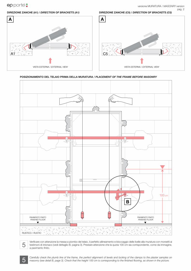
DIREZIONE ZANCHE (A1) / DIRECTION OF BRACKETS (A1) DIREZIONE ZANCHE (C5) / DIRECTION OF BRACKETS (C5)
POSIZIONAMENTO DEL TELAIO PRIMA DELLA MURATURA / PLACEMENT OF THE FRAME BEFORE MASONRY
Verificare con attenzione la messa a piombo del telaio, il perfetto allineamento e bloccaggio delle livelle alla muratura con morsetti ai testimoni di intonaco (vedi dettaglio B, pagina 3). Prestare attenzione che la quota 100 cm sia corrispondente, come da immagine, a pavimento finito.
versione MURATURA / MASONRY versionpag. 2
Carefully check the plumb line of the frame, the perfect alignment of levels and locking of the clamps to the plaster samples on masonry (see detail B, page 3). Check that the height 100 cm is corresponding to the finished flooring, as shown in the picture.
5
5
100 cm
B
RUSTICO / RUSTIC
RUSTICO / RUSTIC
RUSTICO / RUSTIC
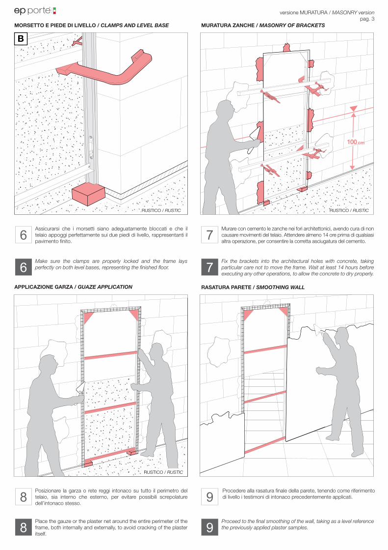
Assicurarsi che i morsetti siano adeguatamente bloccati e che il telaio appoggi perfettamente sui due piedi di livello, rappresentanti il pavimento finito.
Posizionare la garza o rete reggi intonaco su tutto il perimetro del telaio, sia interno che esterno, per evitare possibili screpolature dell’intonaco stesso.
Murare con cemento le zanche nei fori architettonici, avendo cura di non causare movimenti del telaio. Attendere almeno 14 ore prima di qualsiasi altra operazione, per consentire la corretta asciugatura del cemento.
Procedere alla rasatura finale della parete, tenendo come riferimento di livello i testimoni di intonaco precedentemente applicati.
versione MURATURA / MASONRY versionpag. 3
MORSETTO E PIEDE DI LIVELLO / CLAMPS AND LEVEL BASE
APPLICAZIONE GARZA / GUAZE APPLICATION
MURATURA ZANCHE / MASONRY OF BRACKETS
RASATURA PARETE / SMOOTHING WALL
Fix the brackets into the architectural holes with concrete, taking particular care not to move the frame. Wait at least 14 hours before executing any other operations, to allow the concrete to dry properly.
Proceed to the final smoothing of the wall, taking as a level reference the previously applied plaster samples.
Make sure the clamps are properly locked and the frame lays perfectly on both level bases, representing the finished floor.
Place the gauze or the plaster net around the entire perimeter of the frame, both internally and externally, to avoid cracking of the plaster itself.
6
8
7
9
6
8
7
9
VISTA INTERNA / INTERNAL VIEW
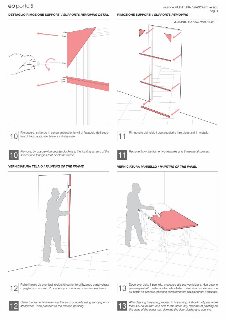
Rimuovere, svitando in senso antiorario, le viti di fissaggio dell’ango-lare di bloccaggio del telaio e il distanziale.
Pulire il telaio da eventuali residui di cemento utilizzando carta vetrata o paglietta in acciaio. Procedere poi con la verniciatura desiderata.
Rimuovere dal telaio i due angolari e i tre distanziali in metallo.
Dopo aver pulito il pannello, procedere alla sua verniciatura. Non devono passare più di 4/5 ore tra una facciata e l’altra. Eventuali accumuli di vernice sul bordo del pannello, possono compromettere la sua apertura e chiusura.
versione MURATURA / MASONRY versionpag. 4
DETTAGLIO RIMOZIONE SUPPORTI / SUPPORTS REMOVING DETAIL
VERNICIATURA TELAIO / PAINTING OF THE FRAME
RIMOZIONE SUPPORTI / SUPPORTS REMOVING
VERNICIATURA PANNELLO / PAINTING OF THE PANEL
Remove from the frame two triangles and three metal spacers.
After cleaning the panel, proceed to its painting. It should not pass more than 4/5 hours from one side to the other. Any deposits of painting on the edge of the panel, can damage the door closing and opening.
Remove, by unscrewing counterclockwise, the locking screws of the spacer and triangles that block the frame.
Clean the frame from eventual traces of concrete using sandpaper or steel wool. Then proceed to the desired painting.
10
12
11
13
10
12
11
13
C
C
D
D
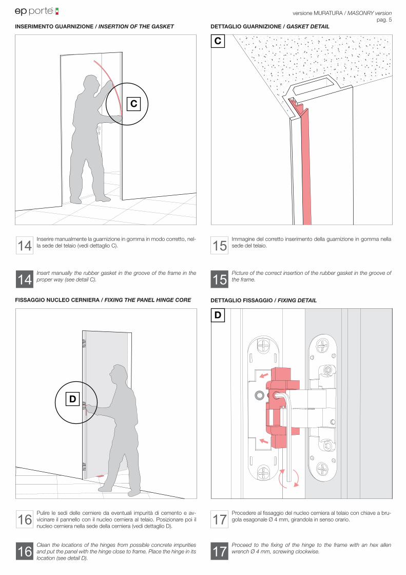
Inserire manualmente la guarnizione in gomma in modo corretto, nel-la sede del telaio (vedi dettaglio C).
Pulire le sedi delle cerniere da eventuali impurità di cemento e av-vicinare il pannello con il nucleo cerniera al telaio. Posizionare poi il nucleo cerniera nella sede della cerniera (vedi dettaglio D).
Immagine del corretto inserimento della guarnizione in gomma nella sede del telaio.
Procedere al fissaggio del nucleo cerniera al telaio con chiave a bru-gola esagonale Ø 4 mm, girandola in senso orario.
versione MURATURA / MASONRY versionpag. 5
INSERIMENTO GUARNIZIONE / INSERTION OF THE GASKET
FISSAGGIO NUCLEO CERNIERA / FIXING THE PANEL HINGE CORE
DETTAGLIO GUARNIZIONE / GASKET DETAIL
DETTAGLIO FISSAGGIO / FIXING DETAIL
Picture of the correct insertion of the rubber gasket in the groove of the frame.
Proceed to the fixing of the hinge to the frame with an hex allen wrench Ø 4 mm, screwing clockwise.
Insert manually the rubber gasket in the groove of the frame in the proper way (see detail C).
Clean the locations of the hinges from possible concrete impurities and put the panel with the hinge close to frame. Place the hinge in its location (see detail D).
14
16
15
17
14
16
15
17
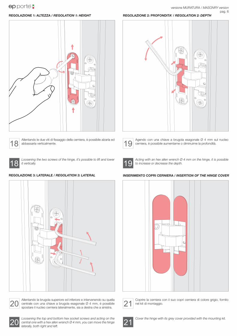
Allentando le due viti di fissaggio della cerniera, è possibile alzarla ed abbassarla verticalmente.
Allentando la brugola superiore ed inferiore e intervenendo su quella centrale con una chiave a brugola esagonale Ø 4 mm, è possibile spostare il nucleo cerniera lateralmente, sia a destra che a sinistra.
Agendo con una chiave a brugola esagonale Ø 4 mm sul nucleo cerniera, è possibile aumentarne o diminuirne la profondità.
Coprire la cerniera con il suo copri cerniera di colore grigio, fornito nel kit di montaggio.
versione MURATURA / MASONRY versionpag. 6
REGOLAZIONE 1: ALTEZZA / REGOLATION 1: HEIGHT
REGOLAZIONE 3: LATERALE / REGOLATION 3: LATERAL
REGOLAZIONE 2: PROFONDITA’ / REGOLATION 2: DEPTH
INSERIMENTO COPRI CERNIERA / INSERTION OF THE HINGE COVER
Acting with an hex allen wrench Ø 4 mm on the hinge, it is possible to increase or decrease the depth.
Cover the hinge with its grey cover provided with the mounting kit.
Loosening the two screws of the hinge, it’s possible to lift and lower it vertically.
Loosening the top and bottom hex socket screws and acting on the central one with a hex allen wrench Ø 4 mm, you can move the hinge laterally, both right and left.
18
20
19
21
18
20
19
21
e.p. s.r.l.via Angelo Maj 1Zona Industriale 124050 Grassobbio (Bergamo) - Italy -
Tel. +39.035.52.53.65 - Fax. +39.035.52.60.99
www.ep-porte.it [email protected] [email protected] department: [email protected]
La
po
rta
Fil
op
are
te n
el
mo
nd
o..
....
.