
Final Report No. 2313 by the Swiss Transportation Safety ...
25
Schweizerische Sicherheitsuntersuchungsstelle SUST Service suisse d’enquête de sécurité SESE Servizio d’inchiesta svizzero sulla sicurezza SISI Swiss Transportation Safety Investigation Board STSB Swiss Transportation Safety Investigation Board STSB CH-3003 Bern Tel. +41 58 466 33 00, Fax +41 58 466 33 01 [email protected] www.stsb.admin.ch Final Report No. 2313 by the Swiss Transportation Safety Investigation Board STSB Concerning the accident involving the DynAero MCR-ULC aircraft, HB-WAR, on 13 December 2015 at Locarno Airport / TI (LSZL)
Transcript of Final Report No. 2313 by the Swiss Transportation Safety ...

Schweizerische Sicherheitsuntersuchungsstelle SUST Service suisse d’enquête de sécurité SESE Servizio d’inchiesta svizzero sulla sicurezza SISI Swiss Transportation Safety Investigation Board STSB
Swiss Transportation Safety Investigation Board STSB CH-3003 Bern Tel. +41 58 466 33 00, Fax +41 58 466 33 01 [email protected] www.stsb.admin.ch
Final Report No. 2313
by the Swiss Transportation
Safety Investigation Board STSB Concerning the accident involving the DynAero MCR-ULC aircraft, HB-WAR, on 13 December 2015 at Locarno Airport / TI (LSZL)

Final Report HB-WAR
Swiss Transportation Safety Investigation Board Page 2 of 25
Ursachen
Der Unfall ist auf eine Notlandung nach einem Motorausfall infolge Unterbruch der Treibstoff-zufuhr zurückzuführen, weil die nicht redundant ausgelegte Spannungsversorgung zu beiden elektrischen Treibstoffpumpen einbrach. Mit hoher Wahrscheinlichkeit wurde der Spannungs-ausfall durch einen Unterbruch der Masseverbindung beim Regler hervorgerufen.
Das Fehlen einer Warnlampe für die Überwachung des Reglergleichrichters hat zum Unfall beigetragen.
Im Rahmen der Untersuchung wurden folgende Faktoren zwar nicht als ursächlich oder bei-tragend, aber dennoch als systemisch risikoreich (factors to risk) erkannt:
fehlendes Verfahren zur Kontrolle des Ladezustandes der Batterie vor dem Flug;
fehlende Beschreibung der Auswirkungen einer unvollständig geladenen Batterie im Flug-betrieb.
Die ordentlichen Instandhaltungsarbeiten sehen keine systematische Überprüfung der auf-gezeichneten Überschreitungen von Betriebsgrenzen vor.

Final Report HB-WAR
Swiss Transportation Safety Investigation Board Page 3 of 25
General information on this report
This report contains the Swiss Transportation Safety Investigation Board’s (STSB) conclusions on the circumstances around and causes of the accident under investigation.
In accordance with article 3.1 of the 10th edition of annex 13, effective from 18 November 2010, to the Convention on International Civil Aviation of 7 December 1944 and article 24 of the Federal Aviation Act, the sole purpose of an aircraft accident or serious incident investigation is to prevent further accidents or serious incidents from occurring. Legal assessment of the circumstances and causes of aircraft accidents and serious incidents is expressly excluded from the aircraft accident investigation. It is therefore not the purpose of this report to establish blame or to determine liability.
Should this report be used for purposes other than those of accident prevention, this statement should be given due consideration.
The German version of this report constitutes the original and is therefore definitive.
All information, unless otherwise indicated, relates to the time of the accident.
All of the times mentioned in this report, unless otherwise indicated, are given in local time (LT). For the region of Switzerland, Central European Time (CET) was the local time at the time of the accident. The relationship between LT, CET and Universal Time Coordinated (UTC) is as follows: LT = CET = UTC + 1 h

Final Report HB-WAR
Swiss Transportation Safety Investigation Board Page 4 of 25
Final Report
Aircraft type DynAero MCR-ULC HB-WAR
Operator Gruppo Volo a Vela Ticino, 6600 Locarno, Switzerland
Owner Gruppo Volo a Vela Ticino, 6600 Locarno, Switzerland
Pilot Swiss citizen, born 1952
Licence European Aviation Safety Agency (EASA) private pilot licence aero-plane (PPL(A)), issued by the Federal Office of Civil Aviation (FOCA)
Flying hours Total 1,069 h During the last 90 days 11:28 h
On the accident type 81 h During the last 90 days 10:00 h
Location 310 m after the end of runway 26L at Locarno Airport / TI (LSZL)
Coordinates 710 547 / 112 949 Altitude 196 m AMSL
Date and time 13 December 2015, 11:53
Type of operation Private, aerotow
Flight rules Visual flight rules (VFR)
Flight phase Take-off
Type of accident Engine failure
Injuries to persons
Injuries Crew members
Passengers Total no. of occupants
Third parties
Fatal 0 0 0 0
Serious 0 0 0 0
Minor 0 0 0 0
None 1 0 0 n/a
Total 1 0 0 0
Damage to aircraft Severely damaged
Third-party damage None

Final Report HB-WAR
Swiss Transportation Safety Investigation Board Page 5 of 25
1 Factual information
1.1 Background and history of the flight
1.1.1 General
The crews’ statements as well as recordings from the Flarm collision warning de-vice and the electronic turbo control unit (TCU) have been used for the following description of the background and history of the flight.
1.1.2 Background
The pilot of HB-WAR held a private pilot licence for aeroplanes and had many years of experience as a tow pilot and as a glider pilot. In addition, he had assisted the maintenance team at the Ticino gliding club (Gruppo Volo a Vela Ticino – GVVT) for several years and was familiar with composite aircraft in particular. The pilot had completed a maintenance seminar on the Rotax 912 and 914 engine types in Grenchen.
The gliding instructor, who controlled the ASK 21 glider, registered as HB-3099, from the rear seat during towing, held a glider pilot’s licence and was also able to draw on many years of experience. The trainee pilot, who sat in the front seat of HB-3099, was just beginning his training as a glider pilot.
The towplane pilot, the gliding instructor and several trainee glider pilots from the Ticino gliding club met at Locarno Airport on the morning of 13 December 2015. The plan was to carry out several training flights around the airport with the trainees using the glider HB-3099. After making the usual preparations and registering the flights with the C-office, the pilot prepared the DynAero MCR-ULC towplane, reg-istered as HB-WAR, for operation.
1.1.3 History of the flight
At 09:58, HB-WAR made its first take-off from grass runway 26L with the glider in tow. Another seven tow flights followed, during each of which the glider released the tow rope at an altitude of about 500 m AMSL, the tow pilot retracted the tow rope during descent using the integrated electrical winch and the towplane re-turned to land on runway 26L. On the ground, the tow pilot left the engine of HB-WAR running between flights each time, until the glider had landed and was pre-pared to take off once more with another trainee pilot.
For the last flight, the towplane and glider lined up on runway 26L as normal and the pilot taxied the towplane forwards slowly until the tow rope to the glider became taut. The flaps of HB-WAR were set for take-off and the additional electric fuel pump (fuel pump 2) was switched on. After setting take-off power at 11:53, the towplane and glider accelerated as normal.
A few seconds after the towplane and glider took off, the towplane pilot noticed that the aircraft’s engine began to run erratically at approximately 70 m above ground and then cut out immediately after that. At the same time, he established that the circuit breakers (CBs) for the radio equipment and the socket for the cigarette lighter on the instrument panel had tripped. The pilot pressed the two CBs in, but they tripped again.
The flight instructor in the glider noticed the reduction in the rate of climb and de-cided to release the tow rope immediately and to make an emergency landing on mown grassland within the airport boundaries, situated to the right of the departure route and approximately 100 m after the end of grass runway 26C. The glider re-mained undamaged.

Final Report HB-WAR
Swiss Transportation Safety Investigation Board Page 6 of 25
With a slight turn to the right, the tow pilot initiated an emergency landing and landed on grassland approximately 310 m after the end of runway 26L. After a landing run of 55 m, the aircraft collided at low speed with the bank of a slightly elevated farm track which runs perpendicular to the runway extension (see illustra-tion 1). In the process, the nose landing gear broke off, the two propeller blades at the bottom were bent and the wing tips were damaged.
The tow pilot was able to leave the wreckage unhurt.
Fire did not break out and there was no damage to the ground.
Illustration 1: Final positions of the two aircraft, HB-WAR and HB-3099, in the extension of runway direction 26
1.2 Meteorological information
1.2.1 General weather conditions
A ridge of high pressure extended from Italy across the Alps to the North Sea.
1.2.2 Weather at the time and location of the accident
The prevailing weather on the Magadino Plain was sunny with cirrostratus clouds and little wind.
Wind Calm conditions
Meteorological visibility 10 km or more, parallel to the runway axis
Weather Sunny
Clouds 5/8 at 22,000 ft
Temperature 5 °C
Dew point -1 °C
Atmospheric pressure (QNH) 1,025 hPa, pressure reduced to sea level, calculated with the values of the ICAO1 standard atmosphere
1 ICAO: International Civil Aviation Organisation

Final Report HB-WAR
Swiss Transportation Safety Investigation Board Page 7 of 25
1.3 Information on the aircraft
1.3.1 General
Registration HB-WAR
Aircraft type MCR-ULC
Characteristics Single-engine, two-seater monoplane in the Ecolight2 category made from a composite con-struction, with fixed landing gear in nose-wheel configuration
Manufacturer DynAero S.A., Darois, France
Year of manufacture 2007
Serial number 349
Approved operation VFR by day, glider tow flights in accordance with towing permit
Engine Rotax 914 UL, s/n 4.419.642
Propeller Three-blade variable-pitch propeller, MT-Propeller Entwicklung GmbH, MTV-34-1-A/164-200
Additional equipment Ballistic recovery system (BRS)
Hours of operation Airframe: 994 h TSN3 Engine: 994 h TSN Engine meter: 1,738 h4 TSN
Landings 2,027
Approved fuel quality Unleaded 95 automotive fuel or Avgas 100 LL
Fuel quality at the time of the accident
Unleaded 95 automotive fuel
Fuel quantity at the time of the accident
19 l
Max. permissible take-off mass 472.5 kg
Mass and centre of gravity The mass of the aircraft was 412.8 kg at the be-ginning of the towing operation and around 395 kg at the time of the accident
At the time of the accident, the mass and centre of gravity were within the permitted limits in ac-cordance with the aircraft flight manual (AFM)
Certificate of registration Issued by FOCA on 27 February 2015
Test certificate Issued by FOCA on 2nd September 2015, valid until 19 July 2017
Permit to fly Issued by FOCA on 31st July 2009
Last EASA check On 2nd September 2015 at 951:38 h TSN
2 Ecolight according to Light Sport Aircraft Statement of Compliance and EASA form 18b.
3 TSN: time since new
4 The difference between the engine meter and engine running time can be attributed to HB-WAR being mainly used as a towplane and the fact that, when it is being used for training operations, the engine is not switched off after every landing while the glider is being prepared for another take-off.

Final Report HB-WAR
Swiss Transportation Safety Investigation Board Page 8 of 25
1.3.2 Maintenance work on HB-WAR
In the period between 27 May 2015 and the time of the accident, a variety of sched-uled and unscheduled maintenance work was carried out. It is evident from the work reports that, for unknown reasons, the engine did not always run smoothly during this period. In order to rectify the problems, the carburettor, the ignition cir-cuit and the current regulator were checked in particular. The current regulator was replaced on 19 August 2015.
In one instance, the technical log contains the comment that the battery was com-pletely exhausted.
1.3.3 Electrical system
The electrical system of HB-WAR is a 14-V direct current (DC) system, which is supplied by a battery with a capacity of 8.0 Ah and an alternating current generator with a rectifier regulator.
The ground connection (GND) between the battery, the metal coating of the engine bulkhead, the rectifier regulator and the electrical consumers is established using electrical cables.5
The electrical system supplies, amongst other things, the two electrical fuel pumps: fuel pump 1 is permanently connected to the main power distributor (+14 V bus); fuel pump 2 is activated via a switch on the instrument panel (see illustration 2). According to the AFM, this ensures that at least one pump can be operated at all times, even if one of the two power sources fails.
In order to ensure operation of the Rotax 914 engine, at least one of these fuel pumps must be in operation at all times to guarantee the supply of fuel to the car-burettors. According to the AFM, in the event that the generator which charges the battery during standard operation via the rectifier regulator fails, the fuel pumps can be operated for a further 30 minutes if the battery is fully charged and the rest of the electrical consumers are switched off. Once the fuel pumps fail, the engine subsequently cuts out due to a lack of fuel supply.
No charge indicator lamp for the rectifier regulator is fitted in the DynAero MCR-ULC, which is why a failure of the generator or of the rectifier regulator can only be identified from a low voltage notification on the voltage indicator and the low volt-age light.
5 The aircraft structure mainly consists of fibre composites and is therefore dielectric.

Final Report HB-WAR
Swiss Transportation Safety Investigation Board Page 9 of 25
Illustration 2: Electrical system of the MCR-ULC (taken from the AFM) with A: master relay, B: fuel pump 1, C: fuel pump 2 and D: capacitor
1.3.4 Rectifier regulator
The task of the rectifier regulator, which was specially developed for use with the Rotax 914 engine, is to convert the alternating current from the generator into direct current with a minimum voltage of 13.8 V. In order to compensate for the voltage fluctuations as fully as possible, a capacitor is also connected between the output of the rectifier regulator and the ground connection.
The rectifier regulator has the following connections (see illustration 2):
G/G: connection to the input for the generator;
L: connection to the charging indicator lamp, which is not fitted in HB-WAR;
C: input for control voltage from the battery;
R and B+: output for charging current to the battery.
According to the manufacturer, a uniform voltage of at least +6 V DC must be ap-plied to input C of the rectifier regulator, so that current is supplied via the output R/B+. When the voltage falls below this value, the regulator switches the outputs R/B+ off, in order to prevent damage to the rectifier regulator or other electrical components. According to the manufacturer, strong over- and under-voltages oc-cur for a short time at the outputs R/B+ when the battery voltage is disconnected from input C, before the rectifier regulator automatically switches itself off. When this happens, according to the manufacturer it is not sufficient for the outputs R/B+
Final Report HB-WAR
Swiss Transportation Safety Investigation Board Page 10 of 25
(charging current) to be connected to input C (control voltage). The rectifier regu-lator is not self-sustaining, but instead always requires an external power supply at input C (battery).
A corresponding warning is attached to the housing of the regulator, which explic-itly prohibits disconnection of the regulator from the battery whilst the engine is running.
In HB-WAR, input C of the rectifier regulator is directly connected to the outputs R/B+. There is no direct, separate connection between input C and the battery.
1.4 Information on the wreckage, the impact, and the accident site
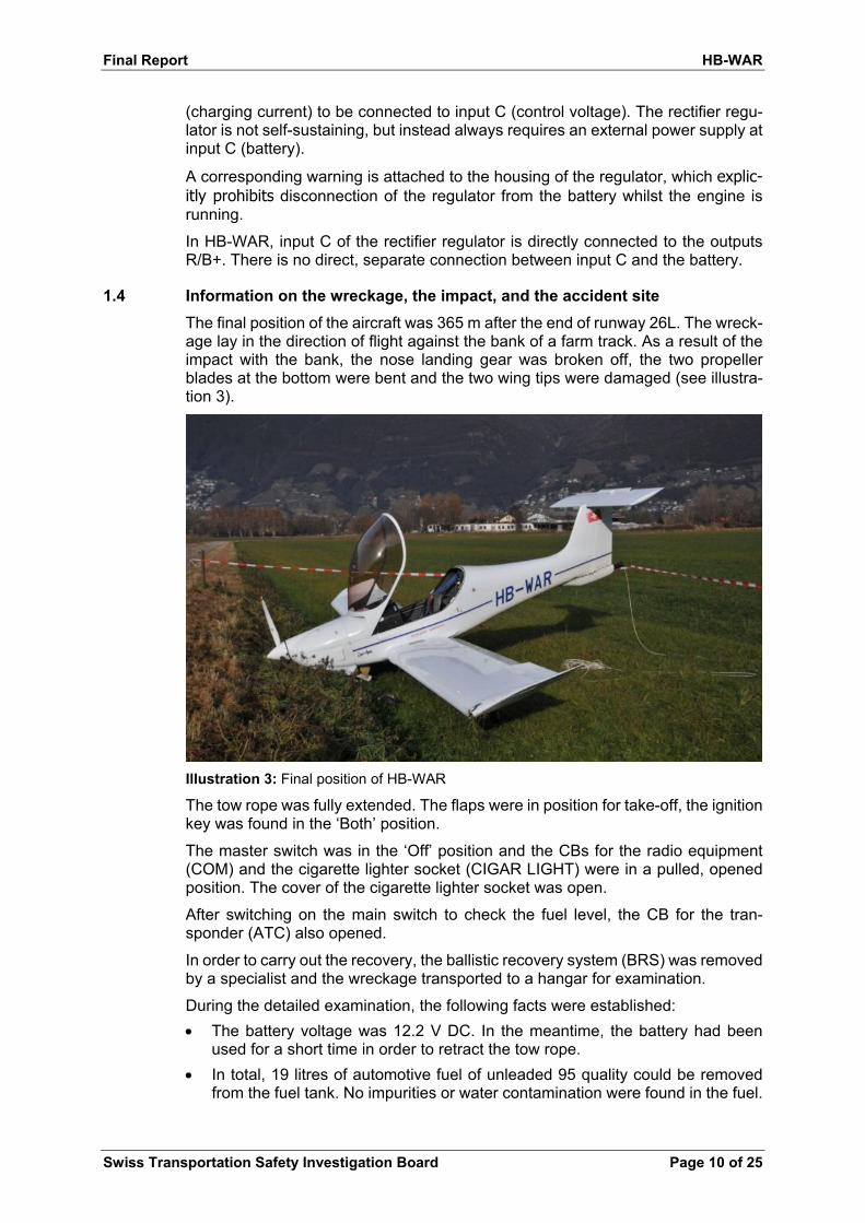
The final position of the aircraft was 365 m after the end of runway 26L. The wreck-age lay in the direction of flight against the bank of a farm track. As a result of the impact with the bank, the nose landing gear was broken off, the two propeller blades at the bottom were bent and the two wing tips were damaged (see illustra-tion 3).
Illustration 3: Final position of HB-WAR
The tow rope was fully extended. The flaps were in position for take-off, the ignition key was found in the ‘Both’ position.
The master switch was in the ‘Off’ position and the CBs for the radio equipment (COM) and the cigarette lighter socket (CIGAR LIGHT) were in a pulled, opened position. The cover of the cigarette lighter socket was open.
After switching on the main switch to check the fuel level, the CB for the tran-sponder (ATC) also opened.
In order to carry out the recovery, the ballistic recovery system (BRS) was removed by a specialist and the wreckage transported to a hangar for examination.
During the detailed examination, the following facts were established:
The battery voltage was 12.2 V DC. In the meantime, the battery had been used for a short time in order to retract the tow rope.
In total, 19 litres of automotive fuel of unleaded 95 quality could be removed from the fuel tank. No impurities or water contamination were found in the fuel.

Final Report HB-WAR
Swiss Transportation Safety Investigation Board Page 11 of 25
Shavings made of a hard plastic material and remnants of rubber O-rings were found in the fuel tank, however these did not affect the flow of the fuel through the suction cup.
The downstream fuel lines, which lie behind the two fuel pumps with non-return valves, were almost empty.
The carburettors’ float housings were only partially filled with fuel.
The two electrical fuel pumps functioned properly.
All CBs were in working order.
The low voltage light worked and lit up below a voltage of 11.8 V DC. This value is not published in the AFM or in the manufacturer’s documentation.
The transponder was electrically damaged and could not be operated.
All other devices were in working order.
The master relay, which separates the main power distributor (+14 V bus) from the battery supply, showed signs of burns on one electrical connection due to a short circuit, but was still functioning (see illustrations 4 and 5).
Illustrations 4 and 5: Master relay, following removal, with scorch marks on one of the electrical connections
The threaded bolt, which had been set into the fuselage structure and was used to mount the rectifier regulator and the ground cables on the cabin floor behind the fire bulkhead, had a total length of 18.50 mm (see illustration 6). The fol-lowing components were fixed on this (from bottom to top): bottom washer (1.01 mm), fixing flange for the rectifier regulator (6 mm), top washer (1.01 mm), cable shoe of the ground cable (0.96 mm) and locking nut (4.8 mm). With all of the components, this gave a total length of 19.80 mm, which meant that the clamping part (plastic insert) of the self-locking nut could not grip the threaded bolt.
The locking nut on the threaded bolt with the cable shoe of the ground cable was not tightened. Illustration 7 shows the threaded bolt with the two washers, the cable shoe of the ground cable and the locking nut after the rectifier regu-lator had been removed.
Both washers exhibited marks on their surfaces that typically occur with a poor electrical connection.

Final Report HB-WAR
Swiss Transportation Safety Investigation Board Page 12 of 25
Illustration 6: The composition of the threaded bolt for fixing the rectifier regulator and the ground cable (cable shoe)
Illustration 7: The threaded bolt with the damaged washers and the cable shoe of the ground cable after the rectifier regulator had been removed
1.5 Recording devices
Various flight and engine parameters from this flight and earlier flights were stored in the TCU (turbo control unit) and in the aircraft’s Flarm, and could be analysed as part of the investigation.
1.5.1 Turbo control unit
The data from the electronic turbo control unit (TCU) was analysed by the engine manufacturer. No noticeable variances had occurred in the last 200 hours of oper-ating time before the accident, nor during the last 20 minutes before the accident flight.
Between the operating times of 355:46 h and 1,537:45 h, an engine overspeed was recorded on numerous occasions – up to a maximum value of 6,209 revolu-tions per minute (RPM). According to the engine manual from Rotax, a speed of 5,800 RPM is permitted for a period of 5 minutes.
In line with the overspeeds, slightly increased air pressure values were also rec-orded in the airbox, which the engine manufacturer assesses as follows, “It is not unusual for the airbox pressure to overshoot to 1,450 mbar for a short time imme-diately after the throttle position is set to 115%. However, here it is striking that for every entry an overspeed was also recorded.”
Locking nut
Cable shoe
Top washer
Regulator
Bottom washer
Locking nut Threaded bolt
19.8
0
18.5
0

Final Report HB-WAR
Swiss Transportation Safety Investigation Board Page 13 of 25
The engine’s technical files do not indicate that any maintenance work took place in connection with these overspeeds.
The AFM states that if the red TCU lamp is continuously illuminated, this indicates that the maximum permissible manifold pressure has been exceeded, and makes the pilot aware that in such a case, the time for which this value is exceeded must be recorded.
The maintenance manual does not require a systematic download of TCU data at any time during scheduled maintenance.
1.5.2 The Flarm of HB-WAR
The last eight flights were recorded on HB-WAR’s Flarm. The recordings which could be assigned to the accident flight and were stored in eight-second intervals during this phase ended abruptly at 10:53:36 UTC. At this point, HB-WAR was in the take-off roll phase.
According to the Flarm’s manufacturer, the low voltage code is no longer recorded when the power supply to the Flarm is suddenly interrupted. Instead, only the last recording is stored. Subsequently, the second that a voltage is reapplied to the system, the file with the Flarm parameters (.igc file) is created. It can therefore be assumed that the electrical on-board power supply of HB-WAR suffered a sudden and complete power outage in the period of eight seconds after the last recording.
1.5.3 The Flarm of glider HB-3099
The analysis of the glider’s Flarm was carried out by a member of the Ticino gliding club and made available to the STSB. The glider stopped climbing a few seconds before 10:54:00 UTC at an altitude of 215 m above mean sea level (AMSL), which corresponds to roughly 20 m above ground level (AGL).
1.6 Examination of the engine
The engine was tested on a dynamometer, using all of the original components of HB-WAR.
The compression measurement prior to the test run showed increased pressure loss values at times, which were still within the manufacturer’s tolerances. Exami-nation of the magnetic bolt only revealed a few small shavings due to wear, but these are normal according to the engine manufacturer and do not indicate any mechanical damage to the engine.
The engine could be started normally on the dynamometer, subsequently ran with-out any problems and achieved all of the required performance values without any discernible losses.
Following this, both electrical pumps were switched off simultaneously at full throt-tle position at a speed of 5,800 RPM. After 6 seconds, uneven running could be detected in the engine along with a drop in speed. After a total time of around 12 seconds, the engine cut out.
The rectifier regulator was tested on a dedicated test bench. A charging voltage of 13.83 V was achieved, which corresponds to the manufacturer’s guidelines (13.5 V to 14 V). Subsequently, the battery was disconnected from the rectifier regulator, which resulted in a complete voltage drop across the rectifier regulator (output R/B+) within a few seconds.

Final Report HB-WAR
Swiss Transportation Safety Investigation Board Page 14 of 25
1.7 Relevant procedural requirements
According to checklists for MCR-ULC (normal procedures), which are carried out on the ground before take-off, only the check of the low voltage light ((“Battery charge (red lamp) … checked”)) is required during the engine check:
4.4.5. Engine ground run
- Parking brake ………………………………………………………………………on
- Oil temperature and pressure………………………………….within green sector
- RPM set …………………………………………………………………….4000 rpm
- Magneto (max drop 300 rpm, max dif. 120 rpm)……….. “L”, BOTH, “R”, BOTH
- Battery charge (red lamp)…………………………………………………..checked
- Min rpm (1'400)……………………………………………………………...checked
- Throttle …………………………………………………………………….2’000 rpm
Various emergency situations are described in chapter 3 of HB-WAR’s AFM, along with the associated procedures that must be carried out by the flight crew. With regard to problems in the electrical system, reference is made to the low voltage light in chapter 3.9.3:
“3.9.3 Low voltage light (red lamp)
Switch off all non-essential electrical equipment and fly to the nearest airfield and land.
Remark: The engine has electrical fuel pumps only. With a failed generator the engine’s fuel supply depends on the battery. The remaining flight time with running engine depends on the charge state of the battery. With a battery in good condi-tions and switched off, consumers expect a remaining flight time of 30 minutes.”
When the low voltage light illuminates, all electrical consumers that are not re-quired must be switched off and the aircraft must land at the nearest airfield. The AFM does not describe from which voltage the low voltage light illuminates.
If the generator or the rectifier regulator fails, the electrical fuel pumps that are needed to operate the engine are supplied solely by the battery. With a fully charged battery, the pumps can continue to operate for a remaining flight time of approximately 30 minutes before they fail, followed by engine failure.
1.8 Additional information
1.8.1 Bad Ragaz accident
On 4 July 2015 at 12:15 LT, the MCR-ULC aircraft, registered as HB-WBA, had an accident at Bad Ragaz aerodrome, which was dealt with in the STSB summary report dated 10 September 2015:
“The towplane and glider were climbing close to Maienfeld when the fault message “low voltage” appeared on board HB-WBA. A short time later, the on-board electri-cal power supply failed.
The glider released the tow rope without a problem and the radio failed. Thereafter the engine suddenly suffered an initial brief loss of power, before losing power completely. The pilot realised that under these circumstances he would no longer reach Bad Ragaz aerodrome.

Final Report HB-WAR
Swiss Transportation Safety Investigation Board Page 15 of 25
He subsequently decided to make an emergency landing in a harvested, unused field south of Maienfeld. No damage was sustained during the soft landing. The pilot was unhurt.
During the inspection that followed, the regulator and flat battery were replaced.”
1.8.2 Installation instructions according to the Rotax installation manual
In the Rotax 914 installation manual, the engine manufacturer gives the following warnings:
“Warning: The connections must be made by the aircraft or airframe manufacturer in accordance with a valid manufacturing regulation such as FAR or EASA and the enclosed connection diagram […].
Warning: It is essential that, in accordance with manufacturing regulation, the fuel pumps have 2 power supplies that are independent of one another.”
The proposed connection diagram provided (see appendix 1) leaves room for in-terpretation as regards the implementation of the redundant power supply. It was established that the aircraft manufacturers who use the Rotax 914 engine used different installation options.
With the Super Dimona, for example, two capacitors are installed in parallel and the AFM includes a warning that prohibits switching off the master switch whilst in flight.
Other manufacturers of ultralight aircraft in which a Rotax 914 is installed provide for a separate, direct connection from the battery to connection C on the rectifier regulator (control voltage) via the ignition switch.

Final Report HB-WAR
Swiss Transportation Safety Investigation Board Page 16 of 25
2 Analysis 2.1 Technical aspects
2.1.1 General
After the accident, the fuel tank was filled with 19 litres of automotive fuel of un-leaded 95 quality. However, there was practically no fuel left in either the fuel lines which led from the two electrical pumps to the carburettors or the two carburettor housings. Following the technical examination, the engine, with all of its original components, could be restarted on the dynamometer without taking further measures.
From this, it was possible to deduce that the engine failure was a result of an in-sufficient fuel supply, because the power supply to the electrical fuel pumps 1 and 2 was interrupted due to a problem in the electrical system. Amongst other things, this problem also manifested itself in the tripped CBs, in the damaged transponder electronics and in the Flarm data that wasn’t recorded shortly before the accident.
The following reasons may have led to the interruption in the power supply to the electrical fuel pumps:
If the master relay is defective or switched off, the battery is disconnected from the main distributor (+14 V bus). Consequently, input C of the rectifier regulator is no longer connected to the battery, but rather is only supplied via the outputs R and B+ of the rectifier regulator. The manufacturer of the rectifier regulator has confirmed that under these circumstances, the rectifier regulator switches itself off after a few seconds in order to prevent internal damage, resulting in the loss of the entire power supply.
The two threaded bolts with which the rectifier regulator and the ground cable were mounted on the cabin floor behind the fire bulkhead were too short, which meant that the locking nut could not be tightened enough to enable its self-securing effect. It is therefore probable that vibrations loosened the locking nut slightly over time and that the electrical contact between the ground cable and the rectifier regulator was interrupted in the process, which leads to the same behaviour as that described above: the power supply from the battery to input C of the rectifier regulator drops with a subsequent total loss of the power sup-ply.
Since the pilot did not manipulate the master switch during the take-off phase and the master relay was still functioning after the accident, the STSB has reached the conclusion that the second scenario is more likely.
2.1.2 Design of the redundant power supply to the fuel pumps
In the installation manual for the Rotax 914 engine, the engine manufacturer em-phasises in particular that the two fuel pumps have to be supplied by two inde-pendent, redundant power sources.
It is imperative that a battery voltage of at least +6 V DC is applied to input C of the rectifier regulator, so that the regulator works correctly and supplies power. It is not sufficient for the outputs R/B+ to be connected to input C, since the rectifier regu-lator is not self-sustaining (see illustration 1). The capacitance of the capacitor in-stalled between input C or one of inputs R/B+ of the rectifier regulator and the ground connection is not sufficient to sustain the voltage at input C in the event of a battery failure, especially if a number of consumers are connected.
The electrical power supply to the fuel pumps of the MCR-ULC with a Rotax 914 engine is therefore not redundant.

Final Report HB-WAR
Swiss Transportation Safety Investigation Board Page 17 of 25
The engine manufacturer Rotax offers the option to install an optional alternator to increase the current supply. This would ensure redundancy of the power supply and make a power failure, as in this case, unlikely.
2.1.3 Design diagram from the engine manufacturer
The design diagram in the engine manufacturer’s installation manual is practically identical to the circuit diagram for the MCR-ULC with regard to the power supply and has an electrical system design that is also not redundant (see appendix 1).
The warnings from Rotax that the fuel pumps must have two power supplies which are independent from one another are not reflected here. One would have ex-pected that the implementation of these warnings would also be taken into consid-eration in the corresponding design diagram.
In addition, provision is also made in the design diagram for a warning light for the rectifier regulator at output L (see illustration 1), which informs the pilot of a rectifier regulator failure. No such warning light is installed in the MCR-ULC and an electri-cal problem is only indicated by the low voltage light and the voltmeter in the event of a low battery voltage. A rectifier regulator failure therefore remains undetected, which was identified as a contributory factor.
2.2 Human and operational aspects
The pilot of the towplane reacted to the engine failure in the appropriate manner by making an emergency landing of the aircraft on mown grassland beyond the end of the runway without any significant changes in direction. The subsequent collision with the bank of the farm track and the associated damage to the aircraft could not be avoided.
The altitude was not sufficient to allow the on-board BRS to be used.
The glider pilots reacted to the loss of power suffered by the towplane in the ap-propriate manner, as the flight instructor immediately assumed control of the flight, released the tow rope and landed the glider on mown grassland with a gentle right turn.
Normal procedures for the MCR-ULC that are to be carried out on the ground be-fore take-off only stipulate that the low voltage light has to be checked during the engine ground run. This does not allow for an assessment of whether the battery is sufficiently charged or of whether the rectifier regulator is working. The checklists do not require that the voltage indicator be checked.
Due to the lack of a charge indicator lamp, a rectifier regulator failure is not visible to the pilot in practice. The low voltage warning light only lights up when the battery voltage falls below 11.8 V DC. However, by this time the battery is already heavily discharged and operation of the fuel pumps for 30 minutes, as described in the AFM, can no longer be guaranteed.
2.3 Further weaknesses
The following further technical and operational weaknesses were discovered dur-ing the investigation, but are not directly related to the course of the accident.
In the “Normal operations” section of the AFM, no provision is made for any systematic check points, at which the battery voltage, which can be read from the voltmeter, must be checked before or during the flight. In addition, there are no procedures defined which ensure that the battery is fully charged before a flight.

Final Report HB-WAR
Swiss Transportation Safety Investigation Board Page 18 of 25
Furthermore, the description of the warning lights in the AFM is inadequate. For example, the warning light with a battery symbol indicates insufficient volt-age in the entire electrical system and not insufficient voltage in the battery, as the pictogram appears to suggest.
The layout of the electrical switches may cause confusion and lead to subse-quent operating errors by the pilot. The master switch, the switch for fuel pump 2 and the switch for the strobe lights are located in the same place on the left-hand instrument panel. The switches have an identical design and only differ in their colour.
According to the maintenance manual, systematic reading of the TCU is not stipulated as part of any periodic maintenance, with the result that any engine overspeed that the pilot failed to notice or report remains undetected. As a consequence, maintenance on the engine and on other affected components that is required in the event of such an overspeed is not carried out, which leads to a significant risk in the further operation of the aircraft.

Final Report HB-WAR
Swiss Transportation Safety Investigation Board Page 19 of 25
3 Conclusions
3.1 Findings
3.1.1 Technical aspects
No pre-existing faults were found in the engine or the fuel system.
The failure of both fuel pumps due to electrical problems meant that the engine was no longer supplied with fuel.
The length of the threaded bolt for fixing the current regulator and the ground connection was too short, with the result that the locking nut could not be tight-ened enough to enable its self-securing effect and the clamping part of the nut (plastic insert) could not grip onto the thread on the bolt.
The locking nut on the threaded bolt, which ensures that the ground connection is in place between the battery and the rectifier regulator, master relay and other electrical components, was not tightened.
All circuit breakers were in working order.
No charge indicator lamp was fitted for the rectifier regulator.
The low voltage light was working and lit up below a voltage of 11.8 V DC. This value is not published in the AFM or in the manufacturer’s documentation.
3.1.2 Crew
The pilot of the towplane and the flight instructor in the glider held the appro-priate licences.
There is no indication of impairment to the crews’ health during the accident flight.
3.1.3 History of the flight
At 09:58, the DynAero MCR-ULC towplane, registered as HB-WAR, took off with the ASK 21 glider, registered as HB-3099, for the first tow flight of the day.
During the ninth take-off for a tow flight at 11:53, HB-WAR suffered a loss of power and subsequent engine failure shortly after take-off.
The gliding instructor released the tow rope and landed the glider on grassland within the boundaries of the airport.
The tow pilot performed an emergency landing on mown grassland.
Whilst rolling to a standstill, the aircraft collided with the bank of a slightly ele-vated farm track.
3.1.4 Operational aspects
According to the AFM, the low voltage light must be checked during the engine check. This does not allow an assessment of whether the battery is sufficiently charged, or whether the rectifier regulator or generator is functioning.
3.1.5 General conditions
The weather had no influence on the development of the accident.

Final Report HB-WAR
Swiss Transportation Safety Investigation Board Page 20 of 25
3.2 Causes
The accident can be attributed to an emergency landing following engine failure due to an interruption in the fuel supply because the non-redundant power supply to both electrical fuel pumps cut out. It is highly likely that the power cut was caused by an interruption in the ground connection at the regulator.
The lack of a warning light for monitoring the rectifier regulator contributed to the accident.
Within the context of the investigation, the following factors were not identified as causal or contributory, but nevertheless as systemic risk factors:
The lack of a procedure for checking the charge state of the battery before the flight;
The fact that there is no description of the effects a partially charged battery could have during flight operations;
The fact that regular maintenance work does not make any provision for a sys-tematic check for any instances in which the operational limits were exceeded.

Final Report HB-WAR
Swiss Transportation Safety Investigation Board Page 21 of 25
4 Safety recommendations, safety advice and measures taken since the accident
Safety recommendations
In accordance with annex 13 of the International Civil Aviation Organisation (ICAO) and article 17 of (EU) regulation no. 996/2010 of the European Parliament and of the Council of 20 October 2010 on the investigation and prevention of accidents and incidents in civil aviation and repealing directive 94/56/EC, all safety recom-mendations listed in this report are intended for the supervisory authority of the competent state, which must decide on the extent to which these recommenda-tions are to be implemented. Nonetheless, any agency, any business and any in-dividual is invited to strive to improve aviation safety in the spirit of the safety rec-ommendations pronounced.
Swiss legislation provides for the following regulation regarding implementation in the Ordinance on the Safety Investigation of Transport Incidents (OSITI):
“Art. 48 Safety recommendations 1 The STSB shall submit the safety recommendations to the competent federal of-fice and notify the competent department of the recommendations. In the case of urgent safety issues, it shall notify the competent department immediately. It may send comments to the competent department on the implementation reports is-sued by the federal office. 2 The federal offices shall report to the STSB and the competent department peri-odically on the implementation of the recommendations or on the reasons why they have decided not to take measures. 3 The competent department may order the competent federal office to implement recommendations.”
The STSB shall publish the answers of the relevant Federal Office or foreign su-pervisory authorities at www.stsb.admin.ch in order to provide an overview of the current implementation status of the relevant safety recommendation.
Safety advice
The STSB may publish safety advice in response to any safety deficit identified during the investigation. Safety advice shall be formulated if a safety recommen-dation in accordance with (EU) regulation no. 996/2010 does not appear to be ap-propriate, is not formally possible, or if the less prescriptive form of a safety advice is likely to have a greater effect. The legal basis for STSB safety advice can be found in article 56 of the OSITI:
“Art. 56 Information on accident prevention
The STSB may publish general relevant information on accident prevention.”
4.1 Short description
In the MCR-ULC with a Rotax 914 engine, fuel is supplied via two electrical fuel pumps. A failure of both fuel pumps, which can, among other things, occur due to a complete outage in the power supply, leads to complete engine failure within seconds at full throttle.
The rectifier regulator, which rectifies and regulates the alternating current from the generator, requires a constant input voltage from the battery in order to operate properly. In the event of battery failure, the rectifier regulator automatically switches itself off in order to prevent internal damage and strong fluctuations in the output

Final Report HB-WAR
Swiss Transportation Safety Investigation Board Page 22 of 25
voltage of the regulator with subsequent damage to further electrical systems. As a result, the power supplies in the electrical system of the MCR-ULC, consisting of a generator with a rectifier regulator and a battery, are not designed to be redun-dant.
Disconnection of the battery from the on-board power supply due to a short circuit, an interruption in the ground cable, a failure of the master relay or simply due to the master switch being switched off, for example, leads to the failure of both fuel pumps and subsequently to engine failure because of a lack of fuel.
4.2 Safety recommendations and safety advice
The safety recommendation no. 511 was emitted with the intermediate report at the 14 July 2016, the ulterior safety recommendations no. 533 and 534 with the final report at the 26 April 2018
4.2.1 Engine failure after take-off
4.2.1.1 Safety deficit
A comparison with other aircraft types registered in Switzerland that are fitted with a Rotax 914 engine shows that the power supply is the same as that of the MCR-ULC. Accordingly, the risk of an engine failure due to a lack of redundancy in the power supply is also present in these aircraft types.
4.2.1.2 Safety recommendation no. 511
The European Aviation Safety Agency (EASA) and the Federal Office of Civil Avi-ation (FOCA) should take appropriate measures to ensure that the electrical sys-tem of aircraft types operated with Rotax 914 engines is equipped with a redundant power supply for the two electrical fuel pumps.
4.2.1.3 Statement from the Federal Office of Civil Aviation
On 14 November 2016, the STSB received the following statement from the Fed-eral Office of Civil Aviation written on 3rd September 2016:
“FOCA / STEH[6] has made contact with DynAero in order to find out what improve-ments to the design (redundancy of the power supply for the fuel pumps) are planned and how these improvements can be incorporated in aircraft previously manufactured. At the present time, we have as yet received no official answer (a secured bypass switch, for example).
However, it should be noted that the likelihood of engine failure in this category (Ecolight) by design is assessed as ‘major/remote’ at most, or as ‘minor/probable’. Hence engine failure can occur every 1,000 to 10,000 hours.
We don’t know if the current design of the DynAero MCR-ULC fulfils these design specifications.
Measures taken up to now:
Information sent to DynAero
Information sent to EASA via IORS7
Stay Safe information published on FOCA platform
6 STEH: Design and Production
7 IORS: Internal occurrence reporting system

Final Report HB-WAR
Swiss Transportation Safety Investigation Board Page 23 of 25
Consequence:
Since further measures are not expedient, FOCA considers the status of this in-vestigation as completed.”
4.2.2 Installation of a warning light for checking the power supply in light aircraft with Rotax 914 engines
4.2.2.1 Safety deficit
The fuel supply in the MCR-ULC with a Rotax 914 engine is provided by two elec-trical fuel pumps. In the event that the generator or rectifier regulator fails, the fuel pumps can continue to operate for a maximum of 30 minutes with a fully charged battery before they fail and the engine subsequently cuts out. For this reason, it is important that a warning light illuminates in the event that the generator or the rec-tifier regulator fails.
4.2.2.2 Safety reccommendation no. 533
The European Aviation Safety Agency (EASA) and the Federal Office of Civil Avi-ation (FOCA) should take appropriate measures to ensure that the operators and owners of aircraft with a Rotax 914 engine are informed of the safety deficit de-scribed and that the electrical system in their aircraft does not exhibit any defects.
4.2.2.3 Safety reccommendation no. 534
The European Aviation Safety Agency (EASA) and the Federal Office of Civil Avi-ation (FOCA) should take appropriate measures to ensure that a failure of the rec-tifier regulator or generator and the discharging of the battery can be detected at any early stage in all aircraft with a Rotax 914 engine.
4.2.3 Engine failure due to a lack of redundancy in the power supply of light aircraft with Rotax 914 engines
4.2.3.1 Safety deficit
The fuel supply in the MCR-ULC with a Rotax 914 engine is provided by two elec-trical fuel pumps. In the event that the generator or rectifier regulator fails, the fuel pumps can continue to operate for a maximum of 30 minutes with a fully charged battery before they fail and the engine subsequently cuts out. For this reason, it is important that the battery is fully charged before every flight.
In the procedures described in the MCR-ULC’s aircraft flight manual (AFM) and that are carried out on the ground before a flight, no provision is made for checking the charge state of the battery. Furthermore, the potential consequences of taking off with a battery that is not fully charged are not described in detail.
4.2.3.2 Safety advice no. 10
Subject: Operation with a battery that is not fully charged
Target group: Owners and operators of aircraft that rely on electrical systems which are absolutely essential for the continuation of a flight
It should be ensured that crews are informed of the potential consequences of taking off with a battery that is not fully charged and that corresponding procedures for checking the charge state of the battery are described in the AFM.
Final Report HB-WAR
Swiss Transportation Safety Investigation Board Page 24 of 25
4.3 Measures taken since the accident
The Federal Office of Civil Aviation (FOCA) has informed the known operators and owners of MCR-ULC aircraft of the safety deficit.
This final report was approved by the Board of the Swiss Transportation Safety Investigation Board STSB (Art. 10 lit. h of the Ordinance on the Safety Investigation of Transportation Inci-dents of 17 December 2014. Bern, 26 April 2019 Swiss Transportation Safety Investigation Board

Final Report HB-WAR
Swiss Transportation Safety Investigation Board Page 25 of 25
Appendix 1: Extract from the BRP installation manual