Fatigue behavior of lubricated Ni-Ti endodontic …abbastanza contraddittori, anche per il fatto che...
13
A. Brotzu et alii, Frattura ed Integrità Strutturale, 28 (2014) 19-31; DOI: 10.3221/IGF-ESIS.28.03 19 Fatigue behavior of lubricated Ni-Ti endodontic rotary instruments A. Brotzu, F. Felli, C. Lupi, C. Vendittozzi Dipartimento ICMA, Sapienza Università di Roma, Roma (Italy) [email protected] E. Fantini Self-employed professional, San Quirico D’Orcia, Siena (Italy) [email protected] ABSTRACT. The use of Ni-Ti alloys in the practice of endodontic comes from their important properties such as shape memory and superelasticity phenomena, good corrosion resistance and high compatibility with biological tissues. In the last twenty years a great variety of nickel-titanium rotary instruments, with various sections and taper, have been developed and marketed. Although they have many advantages and despite their increasing popularity, a major concern with the use of Ni-Ti rotary instruments is the possibility of unexpected failure in use due to several reasons: novice operator handling, presence manufacturing defects, fatigue etc. Recently, the use of an aqueous gel during experimental tests showed a longer duration of the instruments. The aim of the present work is to contribute to the study of the fracture behavior of these endodontic rotary instruments particularly assessing whether the use of the aqueous lubricant gel can extend their operative life stating its reasons. A finite element model (FEM) has been developed to support the experimental results. The results were rather contradictory, also because the Perspex (Poly-methyl methacrylate, PMMA) cannot simulate completely the dentin mechanical behavior; however the results highlight some interesting points which are discussed in the paper. SOMMARIO. L’uso di leghe Ni-Ti negli strumenti endodontici deriva dal fatto che queste presentano importanti proprietà come: la memoria di forma e la superplasticità, buona resistenza alla corrosione e alta compatibilità con i tessuti biologici. Gli strumenti rotanti in nichel-titanio, con varie sezioni e conicità, sono stati sviluppati e commercializzati nell’ultimo ventennio. Pur possedendo innumerevoli vantaggi, gli strumenti in Ni-Ti, tendono ad andare incontro ad una prematura rottura dovuta a diversi fattori. Tra questi a improvvise sovrasollecitazioni indotte da una non buona manualità dell’operatore, a presenza di difetti generati in fase di fabbricazione, a fatica, ecc. Recentemente durante la pratica clinica sugli strumenti sono stati provati diversi tipi di gel al fine di prolungarne la vita operativa. Con questo lavoro si è cercato di dare un contributo allo studio del comportamento a frattura di questi strumenti, in particolare valutando se il gel (acquoso) abbia contribuito efficacemente alla maggior durata degli strumenti e su quali basi. Sono stati effettuati test di fatica e meccanici utilizzando simulacri di Perspex (Poly-methyl methacrylate, PMMA) in sostituzione della dentina. I risultati abbastanza contraddittori, anche per il fatto che il Perspex non può simulare perfettamente la dentina, in ogni caso evidenziano alcuni punti interessanti che vengono discussi nel presente lavoro. Inoltre, a supporto delle indagini sperimentali, è stato sviluppato un modello agli elementi finiti (FEM), che ha permesso di confermare i risultati. KEYWORDS. Endodontic rotary instruments; Ni-Ti Alloy; Fracture Mechanics.
Transcript of Fatigue behavior of lubricated Ni-Ti endodontic …abbastanza contraddittori, anche per il fatto che...
A. Brotzu et alii, Frattura ed Integrità Strutturale, 28 (2014) 19-31; DOI: 10.3221/IGF-ESIS.28.03
19
Fatigue behavior of lubricated Ni-Ti endodontic rotary instruments A. Brotzu, F. Felli, C. Lupi, C. Vendittozzi Dipartimento ICMA, Sapienza Università di Roma, Roma (Italy) [email protected] E. Fantini Self-employed professional, San Quirico D’Orcia, Siena (Italy) [email protected]
ABSTRACT. The use of Ni-Ti alloys in the practice of endodontic comes from their important properties such as shape memory and superelasticity phenomena, good corrosion resistance and high compatibility with biological tissues. In the last twenty years a great variety of nickel-titanium rotary instruments, with various sections and taper, have been developed and marketed. Although they have many advantages and despite their increasing popularity, a major concern with the use of Ni-Ti rotary instruments is the possibility of unexpected failure in use due to several reasons: novice operator handling, presence manufacturing defects, fatigue etc. Recently, the use of an aqueous gel during experimental tests showed a longer duration of the instruments. The aim of the present work is to contribute to the study of the fracture behavior of these endodontic rotary instruments particularly assessing whether the use of the aqueous lubricant gel can extend their operative life stating its reasons. A finite element model (FEM) has been developed to support the experimental results. The results were rather contradictory, also because the Perspex (Poly-methyl methacrylate, PMMA) cannot simulate completely the dentin mechanical behavior; however the results highlight some interesting points which are discussed in the paper. SOMMARIO. L’uso di leghe Ni-Ti negli strumenti endodontici deriva dal fatto che queste presentano importanti proprietà come: la memoria di forma e la superplasticità, buona resistenza alla corrosione e alta compatibilità con i tessuti biologici. Gli strumenti rotanti in nichel-titanio, con varie sezioni e conicità, sono stati sviluppati e commercializzati nell’ultimo ventennio. Pur possedendo innumerevoli vantaggi, gli strumenti in Ni-Ti, tendono ad andare incontro ad una prematura rottura dovuta a diversi fattori. Tra questi a improvvise sovrasollecitazioni indotte da una non buona manualità dell’operatore, a presenza di difetti generati in fase di fabbricazione, a fatica, ecc. Recentemente durante la pratica clinica sugli strumenti sono stati provati diversi tipi di gel al fine di prolungarne la vita operativa. Con questo lavoro si è cercato di dare un contributo allo studio del comportamento a frattura di questi strumenti, in particolare valutando se il gel (acquoso) abbia contribuito efficacemente alla maggior durata degli strumenti e su quali basi. Sono stati effettuati test di fatica e meccanici utilizzando simulacri di Perspex (Poly-methyl methacrylate, PMMA) in sostituzione della dentina. I risultati abbastanza contraddittori, anche per il fatto che il Perspex non può simulare perfettamente la dentina, in ogni caso evidenziano alcuni punti interessanti che vengono discussi nel presente lavoro. Inoltre, a supporto delle indagini sperimentali, è stato sviluppato un modello agli elementi finiti (FEM), che ha permesso di confermare i risultati. KEYWORDS. Endodontic rotary instruments; Ni-Ti Alloy; Fracture Mechanics.

A. Brotzu et alii, Frattura ed Integrità Strutturale, 28 (2014) 19-31; DOI: 10.3221/IGF-ESIS.28.03
20
INTRODUCTION
n the practice of endodontics the introduction of Ni-Ti rotary instruments has reformed root canal treatment by reducing time required to finish the preparation and minimizing procedural errors associated with stainless steel hand instrumentation. The use of Ni-Ti alloys for those applications comes from their important properties such as shape
memory and superelasticity phenomena, good corrosion resistance and high compatibility with biological tissues. The stainless steel instruments, employed in the surgical treatment of root canal, are used as files inserting the instruments in the channel and applying to it a manually axial movement. Therefore, the operating methods give to the instrument almost exclusively tensile stress. These tools are very thin and with little taper in order to reach the root apex. The channels machined with these tools are characterized by surfaces that are not perfect and so the risk of failure in final sealing is highly recurrent. The use of rotary instruments with greater taper allows to get perfectly conical channels, easily sealable, thus reducing the risk of recurrence. Obviously strains are high because the instrument works in a curved channel, thus it is necessary to use strong materials able not only to work dentin but also to get significant deformations. Those deformations have to be fully recovered once instrument is pulled out from the channel. Therefore, superelastic Nitinol® alloys are particularly suitable for such use, being able to withstand deformations exceeding 5%, and then completely retrieving. Despite their increasing popularity, a major concern with the use of Ni-Ti rotary instruments is the possibility of unexpected failure in use [1, 2]. The breaking mode of Ni-Ti rotary instruments may be classified into flexural fatigue and torsional (shear) fracture according to their appearance after breaking [3]. Torsional failure is usually accompanied with macroscopic distortion or unwinding of the flutes adjacent to the fractured end, whereas flexural fatigue often presents as an unexpected fracture without unwinding defects. All manufacturers stated that the only predictable way to prevent flexural fatigue is to discard the instrument regularly after a certain number of uses. The cycle number for instrument re-using depends on the type of tooth that was treated, with the greatest number in anterior teeth and the lowest in molars [4]. In the biomedical field these materials are often subject to cyclical loads that can lead to fatigue failure, and that the particular mechanical behavior of these alloys is derived not from the usual dislocation movement but from the dysplastic transformation austenite-martensite. That transformation allows the material to accumulate large reversible deformations; many researchers, in recent years, have tried to correlate this property with the experimental evidence of studies performed both by fatigue standard tests carried out directly on artifacts for simulating the operating conditions of Nitinol instruments as much as possible. The fatigue life of endodontic instruments, whatever their structure and the stress levels at which they are subjected, is somewhat limited (around 1000 cycles, [5]). Tests directly performed on the drills into channel simulacra show that the fatigue life for these instruments depends on several factors, among which is: the surface defective state, that usually characterizes them, and instrument geometry. However, the fatigue life of the tool in these cases is lower than the theoretical one and does not exceed 500 cycles [6-8]. The initial step of crack formation of these tools is the initial step of trigger as the level of stress applied is such that once the fatigue crack develops, the stress expressed in terms of ΔK applied is so high and close to the levels of rupture of Nitinol alloys [1, 9] that the instruments rapidly fail. It is usually assumed that lubrication during root canal preparation would lower mechanical stress on rotary root canal instruments and therefore prevent instrument failure [10]. However, few data occur in the literature to confirm or refute that opinion. A lubricant may play a physical effect by moving debris away from the rotating instrument. Furthermore, chemical additives could operate on the root canal dentin to facilitate instrumentation, as example Calcium-chelating lubricant, by dissolving inorganic dentin components, softens the root canal wall, whereas sodium hypochlorite (NaOCl) attacks the organic dentin matrix [11]. Thus, both NaOCl and Calcium chelators, like EDTA, can lower root dentin microhardness [12]. The impact of lubricant parameters on simulated root canal instrumentation has been investigated and the performed tests allow to demonstrate that an aqueous lubricant is more beneficial than a gel-type counterpart [13]. The potential difficulty in removing instrument fragments from root canal and a perceived adverse prognostic effect of this procedural complication, together with short time duration of those rotary instruments are the main reason to study the instrument fracture mechanism and how it may be prevented rather than treated. The present research completes a previous preliminary study [14], with the target to determine the incidence and the mode of instrument failure of Ni-Ti rotary systems with and without aqueous lubricant. Furthermore a deepened FEM analysis has been performed on the rotary instruments in order to verify the applied stress.
I
A. Brotzu et alii, Frattura ed Integrità Strutturale, 28 (2014) 19-31; DOI: 10.3221/IGF-ESIS.28.03
21
MATERIALS AND TECHNIQUE
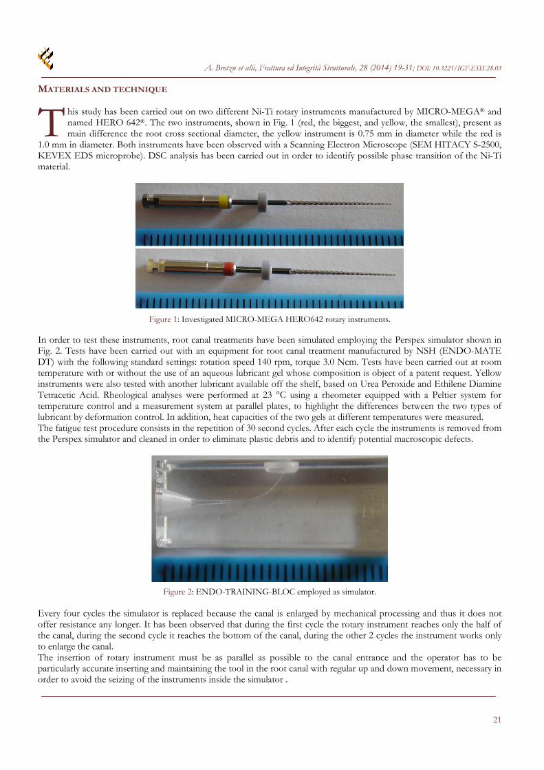
his study has been carried out on two different Ni-Ti rotary instruments manufactured by MICRO-MEGA® and named HERO 642®. The two instruments, shown in Fig. 1 (red, the biggest, and yellow, the smallest), present as main difference the root cross sectional diameter, the yellow instrument is 0.75 mm in diameter while the red is
1.0 mm in diameter. Both instruments have been observed with a Scanning Electron Microscope (SEM HITACY S-2500, KEVEX EDS microprobe). DSC analysis has been carried out in order to identify possible phase transition of the Ni-Ti material.
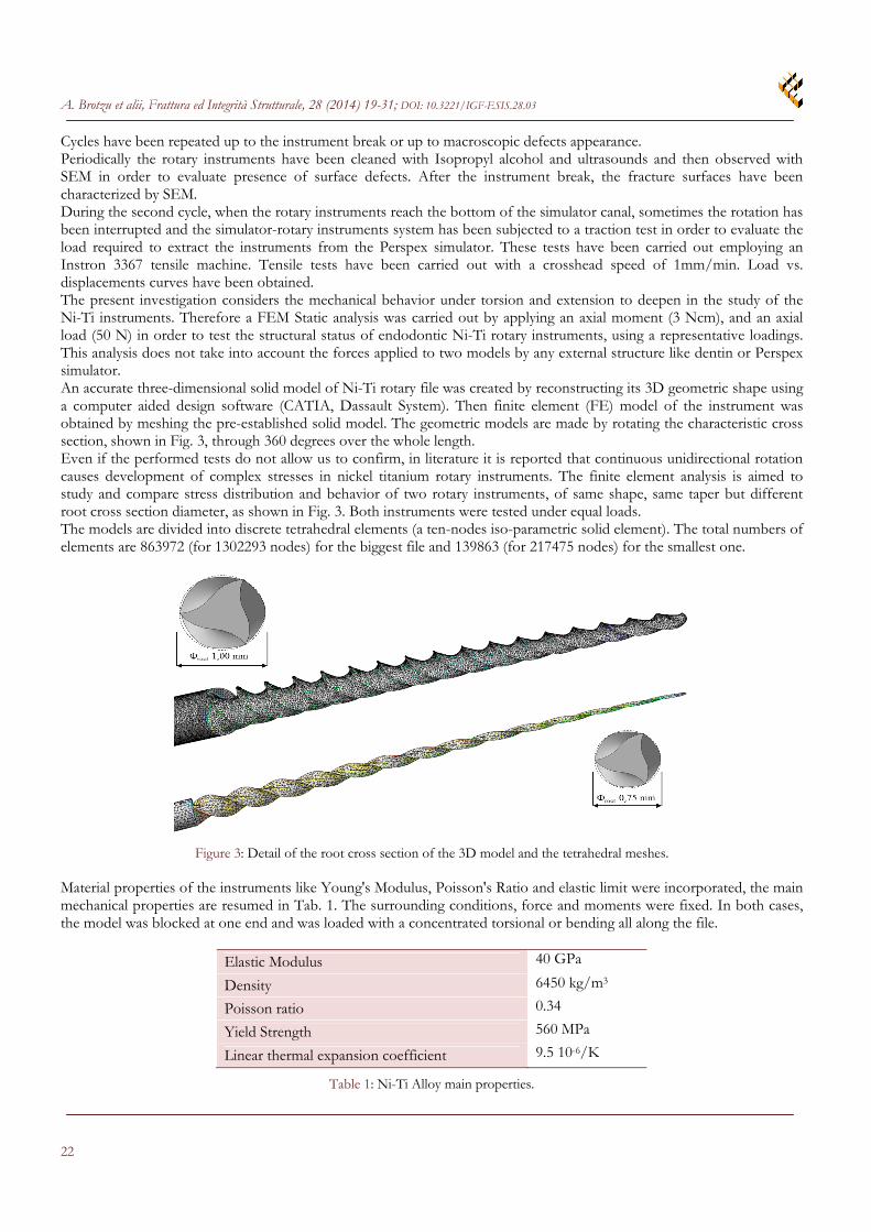
Figure 1: Investigated MICRO-MEGA HERO642 rotary instruments. In order to test these instruments, root canal treatments have been simulated employing the Perspex simulator shown in Fig. 2. Tests have been carried out with an equipment for root canal treatment manufactured by NSH (ENDO-MATE DT) with the following standard settings: rotation speed 140 rpm, torque 3.0 Ncm. Tests have been carried out at room temperature with or without the use of an aqueous lubricant gel whose composition is object of a patent request. Yellow instruments were also tested with another lubricant available off the shelf, based on Urea Peroxide and Ethilene Diamine Tetracetic Acid. Rheological analyses were performed at 23 °C using a rheometer equipped with a Peltier system for temperature control and a measurement system at parallel plates, to highlight the differences between the two types of lubricant by deformation control. In addition, heat capacities of the two gels at different temperatures were measured. The fatigue test procedure consists in the repetition of 30 second cycles. After each cycle the instruments is removed from the Perspex simulator and cleaned in order to eliminate plastic debris and to identify potential macroscopic defects.
Figure 2: ENDO-TRAINING-BLOC employed as simulator. Every four cycles the simulator is replaced because the canal is enlarged by mechanical processing and thus it does not offer resistance any longer. It has been observed that during the first cycle the rotary instrument reaches only the half of the canal, during the second cycle it reaches the bottom of the canal, during the other 2 cycles the instrument works only to enlarge the canal. The insertion of rotary instrument must be as parallel as possible to the canal entrance and the operator has to be particularly accurate inserting and maintaining the tool in the root canal with regular up and down movement, necessary in order to avoid the seizing of the instruments inside the simulator .
T
A. Brotzu et alii, Frattura ed Integrità Strutturale, 28 (2014) 19-31; DOI: 10.3221/IGF-ESIS.28.03
22
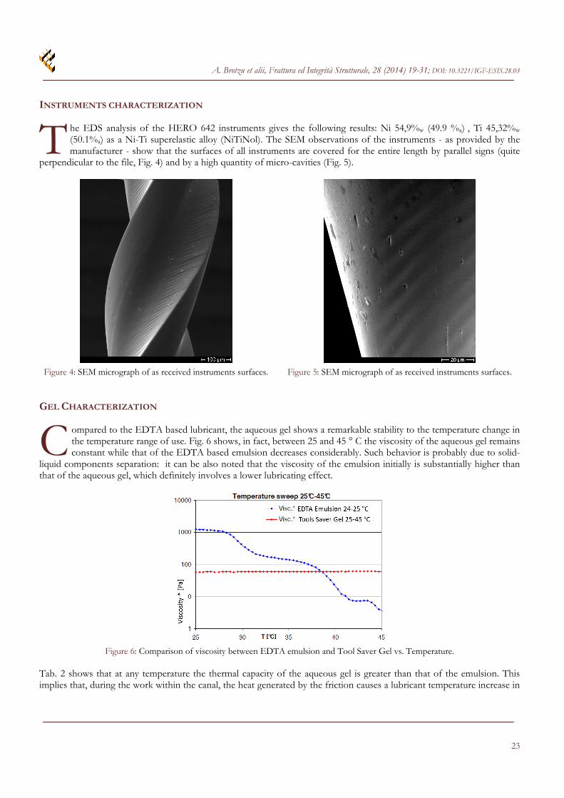
Cycles have been repeated up to the instrument break or up to macroscopic defects appearance. Periodically the rotary instruments have been cleaned with Isopropyl alcohol and ultrasounds and then observed with SEM in order to evaluate presence of surface defects. After the instrument break, the fracture surfaces have been characterized by SEM. During the second cycle, when the rotary instruments reach the bottom of the simulator canal, sometimes the rotation has been interrupted and the simulator-rotary instruments system has been subjected to a traction test in order to evaluate the load required to extract the instruments from the Perspex simulator. These tests have been carried out employing an Instron 3367 tensile machine. Tensile tests have been carried out with a crosshead speed of 1mm/min. Load vs. displacements curves have been obtained. The present investigation considers the mechanical behavior under torsion and extension to deepen in the study of the Ni-Ti instruments. Therefore a FEM Static analysis was carried out by applying an axial moment (3 Ncm), and an axial load (50 N) in order to test the structural status of endodontic Ni-Ti rotary instruments, using a representative loadings. This analysis does not take into account the forces applied to two models by any external structure like dentin or Perspex simulator. An accurate three-dimensional solid model of Ni-Ti rotary file was created by reconstructing its 3D geometric shape using a computer aided design software (CATIA, Dassault System). Then finite element (FE) model of the instrument was obtained by meshing the pre-established solid model. The geometric models are made by rotating the characteristic cross section, shown in Fig. 3, through 360 degrees over the whole length. Even if the performed tests do not allow us to confirm, in literature it is reported that continuous unidirectional rotation causes development of complex stresses in nickel titanium rotary instruments. The finite element analysis is aimed to study and compare stress distribution and behavior of two rotary instruments, of same shape, same taper but different root cross section diameter, as shown in Fig. 3. Both instruments were tested under equal loads. The models are divided into discrete tetrahedral elements (a ten-nodes iso-parametric solid element). The total numbers of elements are 863972 (for 1302293 nodes) for the biggest file and 139863 (for 217475 nodes) for the smallest one.
Figure 3: Detail of the root cross section of the 3D model and the tetrahedral meshes. Material properties of the instruments like Young's Modulus, Poisson's Ratio and elastic limit were incorporated, the main mechanical properties are resumed in Tab. 1. The surrounding conditions, force and moments were fixed. In both cases, the model was blocked at one end and was loaded with a concentrated torsional or bending all along the file.
Elastic Modulus 40 GPa
Density 6450 kg/m3
Poisson ratio 0.34
Yield Strength 560 MPa
Linear thermal expansion coefficient 9.5 10-6/K
Table 1: Ni-Ti Alloy main properties.
A. Brotzu et alii, Frattura ed Integrità Strutturale, 28 (2014) 19-31; DOI: 10.3221/IGF-ESIS.28.03
23
INSTRUMENTS CHARACTERIZATION
he EDS analysis of the HERO 642 instruments gives the following results: Ni 54,9%w (49.9 %a) , Ti 45,32%w (50.1%a) as a Ni-Ti superelastic alloy (NiTiNol). The SEM observations of the instruments - as provided by the manufacturer - show that the surfaces of all instruments are covered for the entire length by parallel signs (quite
perpendicular to the file, Fig. 4) and by a high quantity of micro-cavities (Fig. 5).
Figure 4: SEM micrograph of as received instruments surfaces. Figure 5: SEM micrograph of as received instruments surfaces. GEL CHARACTERIZATION
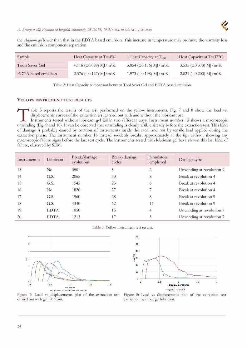
ompared to the EDTA based lubricant, the aqueous gel shows a remarkable stability to the temperature change in the temperature range of use. Fig. 6 shows, in fact, between 25 and 45 ° C the viscosity of the aqueous gel remains constant while that of the EDTA based emulsion decreases considerably. Such behavior is probably due to solid-
liquid components separation: it can be also noted that the viscosity of the emulsion initially is substantially higher than that of the aqueous gel, which definitely involves a lower lubricating effect.
Figure 6: Comparison of viscosity between EDTA emulsion and Tool Saver Gel vs. Temperature. Tab. 2 shows that at any temperature the thermal capacity of the aqueous gel is greater than that of the emulsion. This implies that, during the work within the canal, the heat generated by the friction causes a lubricant temperature increase in
T
C
A. Brotzu et alii, Frattura ed Integrità Strutturale, 28 (2014) 19-31; DOI: 10.3221/IGF-ESIS.28.03
24
the Aqueous gel lower than that in the EDTA based emulsion. This increase in temperature may promote the viscosity loss and the emulsion component separation.
Sample Heat Capacity at T=4°C Heat Capacity at TEnv Heat Capacity at T=37°C
Tools Saver Gel 4.116 (±0.099) MJ/m3K 3.854 (±0.176) MJ/m3K 3.535 (±0.373) MJ/m3K
EDTA based emulsion 2.376 (±0.127) MJ/m3K 1.973 (±0.198) MJ/m3K 2.021 (±0.200) MJ/m3K
Table 2: Heat Capacity comparison between Tool Saver Gel and EDTA based emulsion.
YELLOW INSTRUMENT TEST RESULTS
able 3 reports the results of the test performed on the yellow instruments. Fig. 7 and 8 show the load vs. displacements curves of the extraction test carried out with and without the lubricant use. Instruments tested without lubricant gel fail in two different ways. Instrument number 13 shows a macroscopic
unwinding (Fig. 9 and 10). It can be observed that unwinding is clearly visible already before the extraction test. This kind of damage is probably caused by rotation of instruments inside the canal and not by tensile load applied during the extraction phase. The instrument number 16 instead suddenly breaks, approximately at the tip, without showing any macroscopic failure signs before the last test cycle. The instruments tested with lubricant gel have shown this last kind of failure, observed by SEM.
Instrument n Lubricant Break/damage evolutions
Break/damage cycles
Simulators employed Damage type
13 No 350 5 2 Unwinding at revolution 9
14 G.S. 2065 30 8 Break at revolution 4
15 G.S. 1545 23 6 Break at revolution 4
16 No 1820 27 7 Break at revolution 4
17 G.S. 1960 28 8 Break at revolution 9
18 G.S. 4340 62 16 Break at revolution 9
19 EDTA 1050 15 4 Unwinding at revolution 7
20 EDTA 1213 17 5 Unwinding at revolution 7
Table 3: Yellow instrument test results.
Figure 7: Load vs displacements plot of the extraction test carried out with gel lubricant.
Figure 8: Load vs displacements plot of the extraction test carried out without gel lubricant.
T

A. Brotzu et alii, Frattura ed Integrità Strutturale, 28 (2014) 19-31; DOI: 10.3221/IGF-ESIS.28.03
25
Figure 9: Instrument 13 inserted into the simulator. Figure 10: Instrument 13 after the extraction test. The microcavities observed on the instrument surfaces have evolved producing microcracks since the early test cycles (Fig. 11). Often, these microcracks joint together producing cracks usually in the axial direction. However failure occurs only when this kind of defects develops on the file or in its proximity (Fig. 12). In this point the stress concentration is particularly high.
Figure 11: SEM micrographs of instrument number 16.
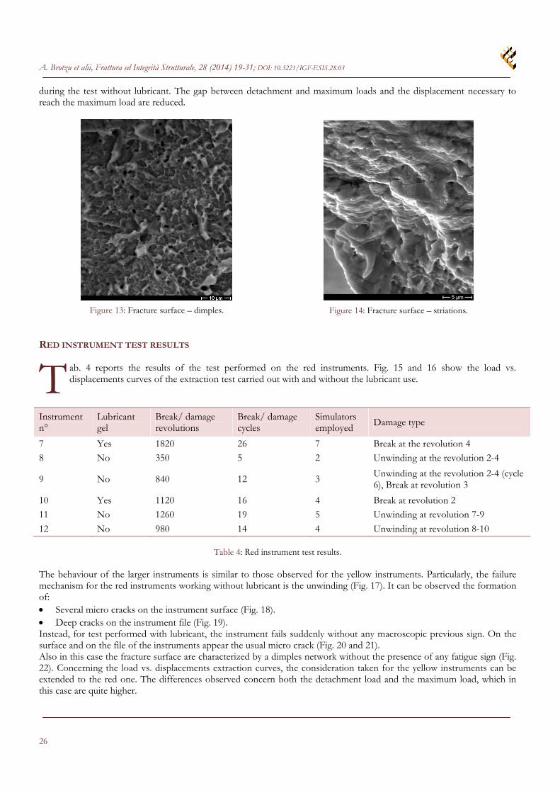
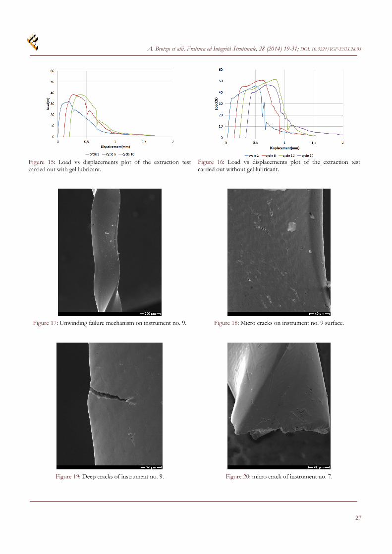
Figure 12: SEM micrographs of instrument number 15. The fracture surfaces are characterized by a wide central area with an extensive network of dimples, indicating a fracture due to overload (Fig 13). The fracture surfaces in proximity of the edges are usually highly worn. Such morphology is due to the fact that the instrument, after the failure, continues to rotate within the Plexiglas canal, until extraction. This makes it difficult to identify the failure mode in these areas. Taking into account that this problem does not allow to observe any signs of fatigue failure, some tests have been performed carefully removing the instrument from the simulacrum as soon as failure takes place, extracting from the plexiglas channel, the cutter broken tip and to observe it with SEM. This specimen part, when broken, does not rotate over and if the instrument is rapidly removed from the canal, it does not even suffers damages resulting from the rubbing of the two fracture surfaces. The morphology of the fracture surface near the edges was studied on those specimens. Particularly, it has been observed on two well preserved specimens that near the cutting edges, dimples are not present, but typical failure striations due to fatigue can be clearly identified (Fig 14). It was also possible to measure the rate of crack propagation in these areas, which is very high, about 0.5 µm/cycle. The study of the load vs. displacement curves allows pointing out the effect of the lubricant gel. During the extraction test carried out without the use of gel the load rises linearly up to a value of about 27 N. At this point, the tool is free and a sudden load drop can be observed. Then the load rises again, but slower than before, and with a typical serrated curve up to the maximum load (approximately 32 N). This last load rise is due to the friction between the canal surface and the instrument. Instead, during extraction test carried out with gel, the load drop, which occurs at the detachment between instrument and canal, is never observed. Both the detachment and the maximum loads are lower than those measured
A. Brotzu et alii, Frattura ed Integrità Strutturale, 28 (2014) 19-31; DOI: 10.3221/IGF-ESIS.28.03
26
during the test without lubricant. The gap between detachment and maximum loads and the displacement necessary to reach the maximum load are reduced.
Figure 13: Fracture surface – dimples.
Figure 14: Fracture surface – striations. RED INSTRUMENT TEST RESULTS
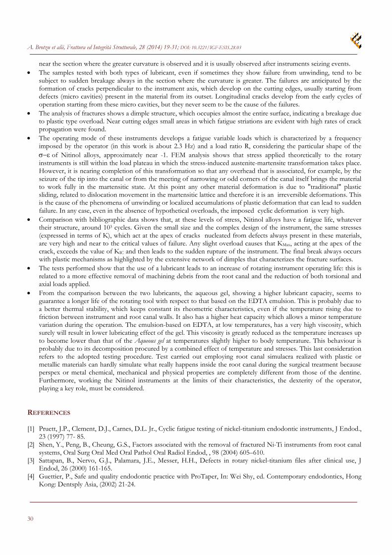
ab. 4 reports the results of the test performed on the red instruments. Fig. 15 and 16 show the load vs. displacements curves of the extraction test carried out with and without the lubricant use.
Instrument n°
Lubricant gel
Break/ damage revolutions
Break/ damage cycles
Simulators employed Damage type
7 Yes 1820 26 7 Break at the revolution 4 8 No 350 5 2 Unwinding at the revolution 2-4
9 No 840 12 3 Unwinding at the revolution 2-4 (cycle 6), Break at revolution 3
10 Yes 1120 16 4 Break at revolution 2 11 No 1260 19 5 Unwinding at revolution 7-9
12 No 980 14 4 Unwinding at revolution 8-10
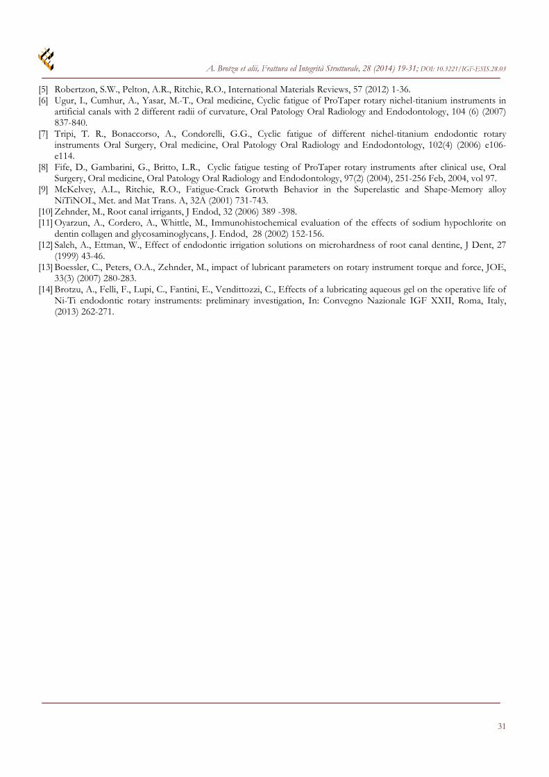
Table 4: Red instrument test results. The behaviour of the larger instruments is similar to those observed for the yellow instruments. Particularly, the failure mechanism for the red instruments working without lubricant is the unwinding (Fig. 17). It can be observed the formation of: Several micro cracks on the instrument surface (Fig. 18). Deep cracks on the instrument file (Fig. 19). Instead, for test performed with lubricant, the instrument fails suddenly without any macroscopic previous sign. On the surface and on the file of the instruments appear the usual micro crack (Fig. 20 and 21). Also in this case the fracture surface are characterized by a dimples network without the presence of any fatigue sign (Fig. 22). Concerning the load vs. displacements extraction curves, the consideration taken for the yellow instruments can be extended to the red one. The differences observed concern both the detachment load and the maximum load, which in this case are quite higher.
T
A. Brotzu et alii, Frattura ed Integrità Strutturale, 28 (2014) 19-31; DOI: 10.3221/IGF-ESIS.28.03
27
Figure 15: Load vs displacements plot of the extraction test carried out with gel lubricant.
Figure 16: Load vs displacements plot of the extraction test carried out without gel lubricant.
Figure 17: Unwinding failure mechanism on instrument no. 9.
Figure 18: Micro cracks on instrument no. 9 surface.
Figure 19: Deep cracks of instrument no. 9.
Figure 20: micro crack of instrument no. 7.

A. Brotzu et alii, Frattura ed Integrità Strutturale, 28 (2014) 19-31; DOI: 10.3221/IGF-ESIS.28.03
28
Figure 21: Micro crack on instrument no. 7 surface.
Figure 22: Fracture surface of instrument number 7. DSC ANALYSIS
he Ni-Ti alloys can show both superelastic behaviour or shape memory effects. It depends on the manufacturing process. The materials employed for the realization of rotary instruments must show a superelastic behaviour. In order to verify if an eventual phase transition - which could modify the Ni-Ti alloy properties- happens in
operation, a DSC analysis in the range of temperature - 30 ÷ 100 °C has been performed. Fig. 23 shows the DSC plot with the four typical phases transformation which characterize the SMA/superelastic alloys. In particular the higher transformation temperature, which usually is the Austenitic Finish Temperature (AF), is 11.55 °C. The material then operates in the superelastic field in which the high recoverable deformations are due to the austenite- detwinned martensite transformation.
11.55°C(I)
8.54°C
15.44°C
0.45
0.50
0.55
0.60
0.65
He
at
Flo
w (
W/g
)
-40 -20 0 20 40 60 80 100
Temperature (°C)Exo Down
Figure 23: DSC Plot. FEM ANALYSIS
he FEM has been performed with the aim to estimate theoretically the deformations applied to the tools in the test conditions. A cylindrical hinge has been inserted at the section where the tool begins to bend, in order to simulate the real local constrain induced by the chanel design. In order to take the curvature of the cutter closer to
T
T

A. Brotzu et alii, Frattura ed Integrità Strutturale, 28 (2014) 19-31; DOI: 10.3221/IGF-ESIS.28.03
29
the real one, two paths were followed. The first consists in applying a load of 1 N on the end of the instrument perpendicularly to the axis of the instrument itself. This load was assessed by flexion test, performed by a tensile machine, blocking the cutter with a straight canal of length equal to that of the straight stretch of the simulacrum and applying a displacement of the tip 3 mm in the direction perpendicular to the axis of the cutter. The applied load vs. tip displacements has been recorded. The second, instead, consists in inserting the tip and imposing a 3 mm failure of the bond. The two simulations gave similar results with the development of a stress state characterized by fibers stretched in the upper part of the instrument and compressed fibers in the lower part. The displacement of the tip of the instrument obtained in the first simulation is slightly less than the desired 3 mm. Fig. 24 and 25 show the results of the two simulations expressed as stresses calculated assuming a homogeneous material with 40 GPa Young modulus. The maximum values are detected near the area where it begins the curvature of the instrument. Tab. 5 shows the calculated maximum tensile and compressive strains. In the simulation with load applied at the tip a of 4.1% is obtained, while with the displacement imposed is significantly higher and amounted to 7.4%.
Tensile Maximum strain Compression Maximum strain
Tip applied load (1N) 2.3 % -1.8 %
Tip Constrain failure 4 % -3.4 %
Table 5: Calculated maximum tensile and compressive strains.
Figure 24: FEM simulation with the Tip applied load.
Figure 25: FEM simulation of the TIP constrain failure. CONCLUSIONS
he study experimental evidences are as follows: The considered rotary instruments fail in two different ways depending on the operating mode. The samples
tested without lubricant often fail by unwinding (high irreversible plastic deformation). The failure takes place T
A. Brotzu et alii, Frattura ed Integrità Strutturale, 28 (2014) 19-31; DOI: 10.3221/IGF-ESIS.28.03
30
near the section where the greater curvature is observed and it is usually observed after instruments seizing events. The samples tested with both types of lubricant, even if sometimes they show failure from unwinding, tend to be
subject to sudden breakage always in the section where the curvature is greater. The failures are anticipated by the formation of cracks perpendicular to the instrument axis, which develop on the cutting edges, usually starting from defects (micro cavities) present in the material from its outset. Longitudinal cracks develop from the early cycles of operation starting from these micro cavities, but they never seem to be the cause of the failures.
The analysis of fractures shows a dimple structure, which occupies almost the entire surface, indicating a breakage due to plastic type overload. Near cutting edges small areas in which fatigue striations are evident with high rates of crack propagation were found.
The operating mode of these instruments develops a fatigue variable loads which is characterized by a frequency imposed by the operator (in this work is about 2.3 Hz) and a load ratio R, considering the particular shape of the of Nitinol alloys, approximately near -1. FEM analysis shows that stress applied theoretically to the rotary instruments is still within the load plateau in which the stress-induced austenite-martensite transformation takes place. However, it is nearing completion of this transformation so that any overhead that is associated, for example, by the seizure of the tip into the canal or from the meeting of narrowing or odd corners of the canal itself brings the material to work fully in the martensitic state. At this point any other material deformation is due to "traditional" plastic sliding, related to dislocation movement in the martensitic lattice and therefore it is an irreversible deformations. This is the cause of the phenomena of unwinding or localized accumulations of plastic deformation that can lead to sudden failure. In any case, even in the absence of hypothetical overloads, the imposed cyclic deformation is very high.
Comparison with bibliographic data shows that, at these levels of stress, Nitinol alloys have a fatigue life, whatever their structure, around 103 cycles. Given the small size and the complex design of the instrument, the same stresses (expressed in terms of K), which act at the apex of cracks nucleated from defects always present in these materials, are very high and near to the critical values of failure. Any slight overload causes that KMax, acting at the apex of the crack, exceeds the value of KIC and then leads to the sudden rupture of the instrument. The final break always occurs with plastic mechanisms as highlighted by the extensive network of dimples that characterizes the fracture surfaces.
The tests performed show that the use of a lubricant leads to an increase of rotating instrument operating life: this is related to a more effective removal of machining debris from the root canal and the reduction of both torsional and axial loads applied.
From the comparison between the two lubricants, the aqueous gel, showing a higher lubricant capacity, seems to guarantee a longer life of the rotating tool with respect to that based on the EDTA emulsion. This is probably due to a better thermal stability, which keeps constant its rheometric characteristics, even if the temperature rising due to friction between instrument and root canal walls. It also has a higher heat capacity which allows a minor temperature variation during the operation. The emulsion-based on EDTA, at low temperatures, has a very high viscosity, which surely will result in lower lubricating effect of the gel. This viscosity is greatly reduced as the temperature increases up to become lower than that of the Aqueous gel at temperatures slightly higher to body temperature. This behaviour is probably due to its decomposition procured by a combined effect of temperature and stresses. This last consideration refers to the adopted testing procedure. Test carried out employing root canal simulacra realized with plastic or metallic materials can hardly simulate what really happens inside the root canal during the surgical treatment because perspex or metal chemical, mechanical and physical properties are completely different from those of the dentine. Furthermore, working the Nitinol instruments at the limits of their characteristics, the dexterity of the operator, playing a key role, must be considered.
REFERENCES [1] Pruett, J.P., Clement, D.J., Carnes, D.L. Jr., Cyclic fatigue testing of nickel-titanium endodontic instruments, J Endod.,
23 (1997) 77- 85. [2] Shen, Y., Peng, B., Cheung, G.S., Factors associated with the removal of fractured Ni-Ti instruments from root canal
systems, Oral Surg Oral Med Oral Pathol Oral Radiol Endod, , 98 (2004) 605–610. [3] Sattapan, B., Nervo, G.J., Palamara, J.E., Messer, H.H., Defects in rotary nickel-titanium files after clinical use, J
Endod, 26 (2000) 161-165. [4] Guettier, P., Safe and quality endodontic practice with ProTaper, In: Wei Shy, ed. Contemporary endodontics, Hong
Kong: Dentsply Asia, (2002) 21-24.
A. Brotzu et alii, Frattura ed Integrità Strutturale, 28 (2014) 19-31; DOI: 10.3221/IGF-ESIS.28.03
31
[5] Robertzon, S.W., Pelton, A.R., Ritchie, R.O., International Materials Reviews, 57 (2012) 1-36. [6] Ugur, I., Cumhur, A., Yasar, M.-T., Oral medicine, Cyclic fatigue of ProTaper rotary nichel-titanium instruments in
artificial canals with 2 different radii of curvature, Oral Patology Oral Radiology and Endodontology, 104 (6) (2007) 837-840.
[7] Tripi, T. R., Bonaccorso, A., Condorelli, G.G., Cyclic fatigue of different nichel-titanium endodontic rotary instruments Oral Surgery, Oral medicine, Oral Patology Oral Radiology and Endodontology, 102(4) (2006) e106-e114.
[8] Fife, D., Gambarini, G., Britto, L.R., Cyclic fatigue testing of ProTaper rotary instruments after clinical use, Oral Surgery, Oral medicine, Oral Patology Oral Radiology and Endodontology, 97(2) (2004), 251-256 Feb, 2004, vol 97.
[9] McKelvey, A.L., Ritchie, R.O., Fatigue-Crack Grotwth Behavior in the Superelastic and Shape-Memory alloy NiTiNOL, Met. and Mat Trans. A, 32A (2001) 731-743.
[10] Zehnder, M., Root canal irrigants, J Endod, 32 (2006) 389 -398. [11] Oyarzun, A., Cordero, A., Whittle, M., Immunohistochemical evaluation of the effects of sodium hypochlorite on
dentin collagen and glycosaminoglycans, J. Endod, 28 (2002) 152-156. [12] Saleh, A., Ettman, W., Effect of endodontic irrigation solutions on microhardness of root canal dentine, J Dent, 27
(1999) 43-46. [13] Boessler, C., Peters, O.A., Zehnder, M., impact of lubricant parameters on rotary instrument torque and force, JOE,
33(3) (2007) 280-283. [14] Brotzu, A., Felli, F., Lupi, C., Fantini, E., Vendittozzi, C., Effects of a lubricating aqueous gel on the operative life of
Ni-Ti endodontic rotary instruments: preliminary investigation, In: Convegno Nazionale IGF XXII, Roma, Italy, (2013) 262-271.