
CODICE BITUBO - BITUBO CODE T0016ECH29Sfilamento fork Fork strip out Q (mm) Differenza interasse...
32
C.D.A. BITUBO s.n.c. – Via A. Volta,24 – 35037 Z.I. Teolo (PD) ITALY – Tel. (+39) 049-990.34.75 Fax (+39) 049-990.34.47 – Cod Fisc. e Part. IVA 02007650282 – E-mail: [email protected] - Internet: http://www.bitubo.com 1 ISTRUZIONI REGOLAZIONE CARTUCCIA ECH SETTING MANUAL ECH CARTRIDGE Rev. 04 del 31/01/2011 Mod. ISTR – ECH Pag. 1 / 32 CODICE BITUBO - BITUBO CODE NUMERO MATRICOLA - SERIAL NUMBER T0016ECH29 BASE Comp. Scheme Reb. Scheme Cost. molla Spring rate (Kg/mm) Precarico Preload (clicks) Estensione Rebound (clicks) Comp. (clicks) Livello olio Oil level (mm) Sfilamento fork Fork strip out Q (mm) Differenza interasse dall’originale. (mm) Lenght difference from the original. (mm) Setting GR50165 GR50164 0.95 5 12 12 135 Orig. +0 BITUBO utilizza e raccomanda – uses and recommends
Transcript of CODICE BITUBO - BITUBO CODE T0016ECH29Sfilamento fork Fork strip out Q (mm) Differenza interasse...
C.D.A. BITUBO s.n.c. – Via A. Volta,24 – 35037 Z.I. Teolo (PD) ITALY – Tel. (+39) 049-990.34.75 Fax (+39) 049-990.34.47 – Cod Fisc. e Part. IVA 02007650282 – E-mail: [email protected] - Internet: http://www.bitubo.com
1
ISTRUZIONI REGOLAZIONE CARTUCCIA ECH SETTING MANUAL ECH CARTRIDGE
Rev. 04
del 31/01/2011
Mod. ISTR – ECH Pag. 1 / 32
CODICE BITUBO - BITUBO CODE NUMERO MATRICOLA - SERIAL NUMBER
T0016ECH29
BASE Comp. Scheme
Reb. Scheme
Cost. molla Spring rate
(Kg/mm)
Precarico Preload (clicks)
Estensione Rebound (clicks)
Comp. (clicks)
Livello olio Oil level
(mm)
Sfilamento fork Fork strip out
Q (mm)
Differenza interasse dall’originale. (mm)
Lenght difference from the original. (mm)
Setting GR50165 GR50164 0.95 5 12 12 135 Orig. +0
BITUBO utilizza e raccomanda – uses and recommends

C.D.A. BITUBO s.n.c. – Via A. Volta,24 – 35037 Z.I. Teolo (PD) ITALY – Tel. (+39) 049-990.34.75 Fax (+39) 049-990.34.47 – Cod Fisc. e Part. IVA 02007650282 – E-mail: [email protected] - Internet: http://www.bitubo.com
2
INDICE MANUALE ISTRUZIONI:
Argomento Pagina Scheda Regolazioni di consegna 1
Presentazione prodotto 3
Precauzioni e sicurezza 3 Regolazione Compressione ed Estensione 4
Regolazione Sfilamento Forcelle 5
Regolazione del Precarico molla 6
Procedura di installazione 7
Verifica e regolazione del Sag veicolo 15
Manutenzione, controlli periodici 16

C.D.A. BITUBO s.n.c. – Via A. Volta,24 – 35037 Z.I. Teolo (PD) ITALY – Tel. (+39) 049-990.34.75 Fax (+39) 049-990.34.47 – Cod Fisc. e Part. IVA 02007650282 – E-mail: [email protected] - Internet: http://www.bitubo.com
3
PRESENTAZIONE PRODOTTO La cartuccia forcella serie ECH è un prodotto di altissima tecnologia realizzato per la massima prestazione, in pista e su strada, ed è tarato secondo parametri definiti dai nostri tecnici del Reparto Corse, secondo le esperienze raccolte nei campionati di maggior prestigio come WSBK,CIV,CEV,IDM,W Endurance . Qui di seguito vi diamo alcuni riferimenti per la personalizzazione della vostra cartuccia Bitubo al fine di ottenere la massima resa.
PRECAUZIONI E SICUREZZA
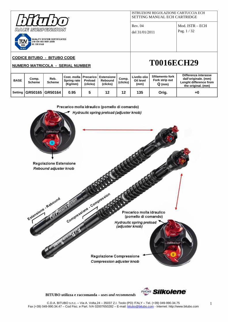
Prima di procedere con lo smontaggio della forcella dalla moto, prendere nota dei valori di sag e della posizione montaggio forcella rispetto a lle piastre di sterzo, nella configurazione al momento utilizzata. Verificare che il Base setting della cartuccia Bitubo (precarico molla e regolazioni idrauliche) corrisponda ai dati riporta ti sulla tabella di pag 1.
Per identificare la posizione delle regolazioni, ve di foto a pag.1
La cartuccia, durante le fasi di produzione viene lubrificata, perciò la presenza di olio o grasso in alcune parti è da ritenersi normale. Al seguito delle istruzioni, è allegata una Tabella Set-Up, utilizzata dai team per annotare le variazioni di regolazione della forcella. I nostri Centri Tecnici Bitubo, sono a Vostra disposizione per aiutarvi a ricercare il migliore Set-Up per la Vostra guida. (elenco Centri Tecnici nella sezione “Assistenza” del ns. sito www.bitubo.com). GARANZIA : Bitubo non potrà essere ritenuta responsabile di operazioni di installazione del prodotto eseguite malamente o diversamente da quanto descritto. Bitubo inoltre non potrà essere ritenuta responsabile di modifiche apportate al prodotto che non siano contenute in questo manuale o che non siano state autorizzate per iscritto. Leggete attentamente questo manuale, per ottenere il massimo delle prestazioni e del rendimento. NOTA BENE : La garanzia del Prodotto cessa nel caso in cui questo venga montato in maniera errata, o modificato senza l’approvazione scritta da Bitubo. Bitubo non potrà essere responsabile di danni, al prodotto o alle persone, nel caso che le istruzioni contenute in questo manuale non vengano seguite esattamente, o nel caso il montaggio del Prodotto non venga effettuato presso una Officina Specializzata, e da personale qualificato.

C.D.A. BITUBO s.n.c. – Via A. Volta,24 – 35037 Z.I. Teolo (PD) ITALY – Tel. (+39) 049-990.34.75 Fax (+39) 049-990.34.47 – Cod Fisc. e Part. IVA 02007650282 – E-mail: [email protected] - Internet: http://www.bitubo.com
4
REGOLAZIONE CARTUCCIA serie “ECH” Per convenzione, il conteggio dei click delle regolazioni idrauliche - in riferimento al setting consigliato indicato nella tabella - inizia dalla posizione “tutto chiuso” (regolazione avvitata a fondo), considerata la posizione”0”.
ATTENZIONE: Non forzare la regolazione quando si ha raggiunto la posizione “0”; potrebbe danneggiare la regolazione stessa e compromettere il buon funzionamento dell’ammortizzatore. ATTENZIONE: Sul tappo superiore si trovano tutte le regolazioni, precarico molla a regolazione idraulica su entrambi i gambali (manopole di regolazione con vite rossa) e regolazioni idrauliche di compressione e di estensione. Le due cartucce svolgono funzioni idrauliche separate: la cartuccia con la manopola di regolazione idraulica con vite gialla svolge la forza idraulica di compressione, mentre la cartuccia con la manopola di regolazione idraulica con vite blu svolge la funzione idraulica di estensione. È normale quindi che comprimendo il gambale sul qua le viene installata la cartuccia di compressione non si senta forza idraulica di estens ione e viceversa per il gambale di estensione.
COME EFFETTUARE LE REGOLAZIONI
COMPRESSIONE ATTENZIONE: per manovrare la manopola di regolazione non è necessario l’ausilio di alcun tipo di attrezzo; fare attenzione a non forzare i finecorsa della regolazione Per convenzione e coerenza con il nostro mono ammortizzatore XXF, la cartuccia con l’idraulica di Compressione (riconoscibile per la presenza di una vite gialla al centro della relativa manopola di regolazione ) va installata sul gambale forcella sinistro della mot o. L’eventuale scambio di questa posizione non comporta alcuna variazione sul funzionamento della forcella ma può creare confusione tra i tecnici che utilizzano i nostri prodotti. Il campo di regolazione utile va dalla posizione “0 (tutto chiuso) a 24 clicks; tuttavia, il margine di regolazione del meccanismo prevede all’incirca 30 clicks totali. Per aumentare lo smorzamento girare manualmente in senso orario la manopola con la vite gialla. Per diminuire lo smorzamento girarla in senso antiorario.
ESTENSIONE
ATTENZIONE: per manovrare la manopola di regolazione non è necessario l’ausilio di alcun tipo di attrezzo; fare attenzione a non forzare i finecorsa della regolazione La cartuccia con l’idraulica di Estensione (riconoscibile per la presenza di una vite blu al centro della relativa manopola di regolazione) va installata sul gambale forcella destro della moto. L’eventuale scambio di questa posizione non comporta alcuna variazione sul funzionamento della forcella ma può creare confusione tra i tecnici che utilizzano i nostri prodotti. Il campo di regolazione utile va dalla posizione “0 (tutto chiuso) a 24 clicks; tuttavia, il margine di regolazione del meccanismo prevede all’incirca 30 clicks totali. Per aumentare lo smorzamento girare manualmente in senso orario la manopola con la vite blu. Per diminuire lo smorzamento girarla in senso antiorario.

C.D.A. BITUBO s.n.c. – Via A. Volta,24 – 35037 Z.I. Teolo (PD) ITALY – Tel. (+39) 049-990.34.75 Fax (+39) 049-990.34.47 – Cod Fisc. e Part. IVA 02007650282 – E-mail: [email protected] - Internet: http://www.bitubo.com
5
REGOLAZIONE SFILAMENTO FORCELLE
Le cartucce riportanti il codice finale ECH29 ripropongono la stessa lunghezza (alla massima estensione come da schema sottostante, in quanto provviste di contro molla interna) delle cartucce originali quindi una volta installate la lunghezza delle forcelle sarà la medesima di quelle originali. Qualora si dovesse installare una cartuccia con codice finale ECHA9 ovvero di lunghezza differente dall’originale, il valore “differenza interasse dall’originale” viene riportato in tabella “base setting” a pagina 1. Ripristinare quindi la corretta altezza dell’avantreno (vedi disegno sottostante): il valore della quota Q è riportato in tabella “base setting” a pagina 1: Q = orig. > la misura è come il montaggio originale (fare rife rimento al Manuale Tecnico del veicolo). Q = valore (esempio:10mm) > posizionare le forcelle alla misura indicata. I valori di posizionamento forcella sono dati rilevati dal nostro Reparto Corse questi sono stati verificati accoppiando il montaggio del KIT ECH con il nostro ammortizzatore posteriore. Accoppiando altro tipo di prodotto al posteriore potrebbe anche verificarsi un’instabilità del veicolo
ATTENZIONE: Le quote ciclistiche sono il risultato di lunghi collaudi da parte della Casa Costruttrice stessa, e la quota Q è stata definita per fornire maneggevolezza e stabilità in tutta sicurezza. Un aggiustamento di 2 o 3mm realizza una grande variazione sul comportamento del veicolo.
Una variazione della quota Q modifica alcune quote ciclistiche prescritte dalla Casa costruttrice del veicolo, e può causare una diminuzione della stabilità del veicolo stesso, sia in marcia che in parcheggio (sul cavalletto centrale o stampella laterale), pregiudicandone il comportamento di guida e la sicurezza d’uso.
ESTENDERE CON FORZA = 30Kgf EXTEND WITH FORCE = 30Kgf
INTERASSE / LENGHT

C.D.A. BITUBO s.n.c. – Via A. Volta,24 – 35037 Z.I. Teolo (PD) ITALY – Tel. (+39) 049-990.34.75 Fax (+39) 049-990.34.47 – Cod Fisc. e Part. IVA 02007650282 – E-mail: [email protected] - Internet: http://www.bitubo.com
6
REGOLAZIONE DEL PRECARICO MOLLA
Il range di regolazione è 12mm. Ad ogni click (mezzo giro della manopola di regolazione) corrisponde 1mm di precarico della molla. Per aumentare il valore di precarico molla ruotare manualmente in senso orario la manopola di regolazione. Per diminuire tale valore di precarico, ruotarla in senso antiorario. Per facilitare la manovrabilità della manopola di regolazione è possibile utilizzare l’attrezzo incluso nel kit, cod. 09901000.
I valori di precarico sono tanto importanti quanto la quota di sfilamento delle forcelle. Il precarico definisce l’altezza a terra della moto, e l’assetto dinamico in curva quindi i valori di angolo forcella, avancorsa ecc. che caratterizzano il comportamento del veicolo. Generalmente i valori di precarico ottimali vanno d a 3 a 8mm . Per ottimizzare la regolazione del precarico vedi paragrafo “REGOLAZIONE E MISURAZIONE DEI SAG”.
ATTENZIONE: questo tipo di cartuccia forcella è dotata di contromolla interna. Verificare quindi le misure a sospensione completamente estesa non solo sollevando la moto da terra, ma forzando la sospensione in estensione, per comprimere totalmente la contromolla interna.
Il precarico molla è lo schiacciamento che questa subisce quando è installata sulla cartuccia.
PRECARICO=F-M
M F
MANOPOLA DI REGOLAZIONE DEL PRECARICO MOLLA PRELOAD SPRING ADJUSTER KNOB
ATTREZZO/TOOL cod. 09901000
C.D.A. BITUBO s.n.c. – Via A. Volta,24 – 35037 Z.I. Teolo (PD) ITALY – Tel. (+39) 049-990.34.75 Fax (+39) 049-990.34.47 – Cod Fisc. e Part. IVA 02007650282 – E-mail: [email protected] - Internet: http://www.bitubo.com
7
PROCEDURA DI INSTALLAZIONE
ATTENZIONE: il tappo superiore e l’eventuale distanziale all’ estremità inferiore della cartuccia non vengono serrati da Bitubo in quanto per le oper azioni di montaggio devono per forza essere rimossi e serrati successivamente. L’esperienza nell’utilizzo racing con il team BE1 n el campionato mondiale WSS, ha portato a migliorare il comportamento della moto nella fase d i inserimento in curva, rimuovendo un tampone di fine corsa di altezza 5mm per ciascuna d elle due cartucce. Questa operazione aumenta l’escursione della forcella di 5mm e richie de particolare attenzione in quanto si va a sfruttare la massima corsa a disposizione; va quind i effettuata presso uno dei nostri Centri Tecnici autorizzati. Nell’utilizzo va verificata attentamente l’escursio ne della forcella intervenendo, se necessario, sul livello dell’olio per evitare di arrivare brusc amente a fine escursione.
1- Mettere la moto su appositi supporti idonei a scaricare il peso da entrambe le ruote della moto per
lavorare in sicurezza con la moto priva di ruota anteriore e forcelle. 2- Rilevare la quota Q rappresentata sullo schema del paragrafo “REGOLAZIONE SFILAMENTO
FORCELLE” a pagina 5 e fare riferimento ai consigli tecnici in esso riportati. 3- Allentare le viti della piastra superiore di sterzo che assicurano il bloccaggio dei gambali forcella
(indicate con le frecce nella foto 1 di esempio illustrativo) e allentare di 1 giro i tappi superiori delle forcelle originali.
4- Rimuovere i gambali forcella dal veicolo: per la rimozione dei gambali forcella e dei particolari originali attenersi alle indicazioni della Casa costruttrice del veicolo (Libretto Uso/Manutenzione-Manuale di Officina). (OPERAZIONI DA RIPETERSI SU CIASCUNO DEI DUE GAMBALI FORCELLA)
5- Assicurare il piedino forcella in morsa, come da foto 4, facendo attenzione a non rovinarlo (consigliamo di utilizzare una morsa con mordacchie in alluminio tenero o in plastica).
6- Svitare il tappo superiore originale del gambale forcella, allentato al punto 3, dal fodero. 7- Abbassare lentamente il fodero e svitare il tappo dallo stelo interno della cartuccia e rimuoverlo (vedi
esempio in foto 2).
8- Sfilare gli spessori se presenti e la molla originale. 9- Rimuovere la cartuccia originale completa di tutti i suoi componenti e successivamente separare il
fodero dalla stelo forcella: visto la varietà di forcelle è necessario fare riferimento alle indicazioni della Casa costruttrice del veicolo (Libretto Uso/Manutenzione-Manuale di Officina).
10- Fissare in morsa il piedino forcella, con lo stelo in posizione verticale. 11- Fissare la chiave 00243 più boccola 00324 (steli forcella Ø41mm) o 00323 (steli forcella Ø43mm) sullo
stelo forcella. 12- Con la pistola termica scaldare la zona di accoppiamento stelo su piedino (foto 3) e, in alcuni casi, con
chiave Torx svitare il grano di sicurezza posto sul piedino (foto 4) e successivamente svitare la canna dal piedino stesso (ATTENZIONE! Scaldare il pezzo a temperatura elevata per far si che la colla originale perda efficacia).
1
PROCEDURA PER FORCELLE DEL TIPO SHOWA BIG PISTON
(esempio: Kawasaki ZX6-R ’09 e Suzuki GSX-R ’09)
2

C.D.A. BITUBO s.n.c. – Via A. Volta,24 – 35037 Z.I. Teolo (PD) ITALY – Tel. (+39) 049-990.34.75 Fax (+39) 049-990.34.47 – Cod Fisc. e Part. IVA 02007650282 – E-mail: [email protected] - Internet: http://www.bitubo.com
8
13- Rimuovere completamente il registro del precarico molla posto sul piedino forcella e rimuove tutti i suoi componenti. (foto 5-6-8)
14- Riavvitare soltanto la ghiera esterna “A” con la relativa vite “B” sul piedino forcella. 15- Con un’attrezzo adeguato sfilare l’O-Ring di tenuta originale posto all’interno del piedino, ed eliminare
ranella di acciaio originale. (foto 7) 16- Detergere accuratamente tutte le parti originali ed eliminare tutti i residui di collante. 17- Rimuovere dall’attacco inferiore della cartuccia ECH Bitubo il distanziale “D” che è avvitato
manualmente (senza essere stato serrato) sul tappo inferiore cartuccia “C” (foto 9). 18- Re inserire l’ O-Ring originale all’interno del piedino, e al posto della ranella di acciaio originale inserire
il distanziale “D” fino al perfetto alloggiamento sul fondo del piedino (si deve avvertire la forzatura del distanziale “D” nel passaggio dell’O-ring) (foto 10).
A
B
A
3 4
5 6 7
8

C.D.A. BITUBO s.n.c. – Via A. Volta,24 – 35037 Z.I. Teolo (PD) ITALY – Tel. (+39) 049-990.34.75 Fax (+39) 049-990.34.47 – Cod Fisc. e Part. IVA 02007650282 – E-mail: [email protected] - Internet: http://www.bitubo.com
9
19- Cospargere con colla frena filetti a resistenza media (esempio Loctite 242 o equivalente) la filettatura dello stelo, avvitare lo stelo forcella sul piedino, e stringere a fondo servendosi della chiave 00243 + boccola 00324 (steli forcella Ø41mm) o 00323 (steli forcella Ø43mm). (foto 11)
20- Per reinserire il fodero nello stelo, visto la varietà di forcelle, fare riferimento alle indicazioni della Casa Costruttrice del veicolo (Libretto Uso/Manutenzione-Manuale di Officina). N.B.: Consigliamo, per una migliore scorrevolezza, di verificare il gioco delle boccole stelo-fodero: boccole superiori da 0.10 a 0.15mm, inferiori da 0.08 a 0.12mm. In caso contrario le boccole andranno adattate o sostituite. In alternativa è possibile consultare il catalogo Bitubo per verificare la possibile applicazione del kit di scorrimento “KITS” costituito da boccole con tolleranze già ottimizzate dal Reparto Corse Bitubo e paraoli ad alto scorrimento. Al montaggio, ingrassare adeguatamente con grasso Bitubo apposito, codice 997608.
21- Rimuovere dalla cartuccia ECH Bitubo il tappo superiore, il distanziale e la molla. E sufficiente inserire la chiave a forchetta “E” fornita in dotazione cod.09900907 sul controdado dell’asta pompante “F” e svitare manualmente il tappo superiore in quanto non viene serrato da Bitubo per facilitare appunto questa operazione. ATTENZIONE: una volta rimosso il tappo superiore, n on manovrare le manopole di regolazione.
22- Inserire la cartuccia completa all’interno del gambale forcella, e fissarla con l’attrezzo speciale fornito nel Kit cod.00397 inserendolo dalla parte che si accoppia con il tappo inferiore cartuccia “C” (vedi schema 2 a pag.11. Dall’altra estremità “G” inserire una chiave a brugola da 19mm e serrare a 28Nm. ATTENZIONE: Inserire cartuccia compressione a sinistra, e cartuccia estensione a destra .
C
D
E
F
TAPPO SUPERIORE UPPER CAP
DISTANZIALE MOLLA SPRING SPACER
MOLLA SPRING
9
10 11
12

C.D.A. BITUBO s.n.c. – Via A. Volta,24 – 35037 Z.I. Teolo (PD) ITALY – Tel. (+39) 049-990.34.75 Fax (+39) 049-990.34.47 – Cod Fisc. e Part. IVA 02007650282 – E-mail: [email protected] - Internet: http://www.bitubo.com
10
23- Portare sia il fodero che l’asta pompante in posizione di massima compressione per effettuare un
corretto livello d’olio: attenzione a comprimere manualmente l’asta pompante spingendola dall’estremità filettata senza forzare sull’astina interna. Versare olio Bitubo SAE 0W30 cod. 997637 fornito nella confezione, sino ad ottenere il livello prescritto nella tabella “base setting” a pagina 1 dal bordo del fodero esterno. Eseguire alcuni movimenti di compressione-estensione del fodero esterno in modo che venga spurgata eventuale aria.
24- Controllare il livello sempre con il fodero e l’asta pompante in posizione di massima compressione, e all’ occorrenza, aggiungere olio.
25- Avvitare completamente il controdado “F” (figura 14). 26- Inserire la molla e il distanziale rimossi al punto 21. 27- Avvitare manualmente il tappo fino a portarlo in battuta sullo stelo cartuccia; ATTENZIONE:
ASSICURARSI CHE SIA ARRIVATO BENE IN BATTUTA.
Nota: per distinguere con esattezza la cartuccia di estensione da quella di compressione vedere immagine a pagina 1 riportante le diversità esterne tra le due cartucce.
28- Avvicinare il controdado “F” al tappo e serrarlo contro di esso con la chiave a forchetta “E” tenendo
bloccato il tappo con la chiave cod.00398 fornita in dotazione.(sulla chiave è possibile inserire un qualsiasi attrezzo commerciale con attacco quadro da ½ pollice). ATTENZIONE: non oltrepassare la coppia di serraggio di 9.0Nm.
29- Portare il fodero forcella verso il tappo della cartuccia avvitare il tappo come da figura 14, trattenendo manualmente il fodero fino al completo avvitamento (al momento non è necessario serrarlo completamente).
30- Rimontare i gambali forcella sulla moto, seguendo le istruzioni contenute nel Manuale di Officina della Casa Costruttrice del veicolo:una volta serrate le viti della piastra inferiore forcella che assicurano il bloccaggio dei gambali forcella e prima di serrare le relative viti della piastra superiore (indicate con le frecce nella foto 1 di esempio illustrativo), serrare i tappi superiori a 15Nm.
ESTREMITA’ INFERIORE CARTUCCIA LOWER CARTRIDGE END
C
G
F
ATTACCO QUADRO DA 1/2” SQUARE ATTACHMENT 1/2”
E
ATTREZZO/TOOL cod. 00398
14
FODERO OUTER TUBE
13

C.D.A. BITUBO s.n.c. – Via A. Volta,24 – 35037 Z.I. Teolo (PD) ITALY – Tel. (+39) 049-990.34.75 Fax (+39) 049-990.34.47 – Cod Fisc. e Part. IVA 02007650282 – E-mail: [email protected] - Internet: http://www.bitubo.com
11
RIPRENDE DAL PUNTO 8
31- Per reinserire il fodero nello stelo, visto la varietà di forcelle, fare riferimento alle indicazioni della Casa Costruttrice del veicolo (Libretto Uso/Manutenzione-Manuale di Officina). N.B.: Consigliamo, per una migliore scorrevolezza, di verificare il gioco delle boccole stelo-fodero: boccole superiori da 0.10 a 0.15mm, inferiori da 0.08 a 0.12mm. In caso contrario le boccole andranno adattate o sostituite. In alternativa è possibile consultare il catalogo Bitubo per verificare la possibile applicazione del kit di scorrimento “KITS” costituito da boccole con tolleranze già ottimizzate dal Reparto Corse Bitubo e paraoli ad alto scorrimento. Al montaggio, ingrassare adeguatamente con grasso Bitubo apposito, codice 997608.
32- Rimuovere dalla cartuccia ECH Bitubo il tappo superiore, il distanziale e la molla. E sufficiente inserire la chiave a forchetta “E” fornita in dotazione cod.09900907 sul controdado dell’asta pompante “F” e svitare manualmente il tappo superiore in quanto non viene serrato da Bitubo per facilitare appunto questa operazione. ATTENZIONE: una volta rimosso il tappo superiore, n on manovrare le manopole di regolazione.
33- La maggior parte delle cartucce si presenta come da schema 1 ovvero con il distanziale “D” che è avvitato manualmente (senza essere stato serrato) sul tappo inferiore cartuccia “C”: disassemblare il distanziale e fissarlo al piedino della forcella come da schema 1.
34- Inserire la cartuccia completa all’interno della forcella e fissarla al distanziale appena montato come da schema 1) . All’ estremità “G” inserire una chiave a brugola da 19mm e serrare a 28Nm. ATTENZIONE: Inserire cartuccia compressione a sinistra, e cartuccia estensione a destra .
PROCEDURA PER FORCELLE DEL TIPO TRADIZIONALE
E
F
TAPPO SUPERIORE UPPER CAP
DISTANZIALE MOLLA SPRING SPACER
MOLLA SPRING
15

C.D.A. BITUBO s.n.c. – Via A. Volta,24 – 35037 Z.I. Teolo (PD) ITALY – Tel. (+39) 049-990.34.75 Fax (+39) 049-990.34.47 – Cod Fisc. e Part. IVA 02007650282 – E-mail: [email protected] - Internet: http://www.bitubo.com
12
D
C
VITE E RONDELLA ORIGINALI SERRARE CON COLLA BLOCCANTE TIPO LOCTITE 638 O
EQUIVALENTE 30Nm ORIGINAL SCREW AND WASHER
TIGHTEN WITH FIXED GLUE AS LOCTITE 638 OR SIMILAR 30Nm
SCHEMA 1 / 1 SCHEME Cartucce con distanziale inferiore
Cartridge with lower spacer
ATTREZZO/TOOL cod.00397
G

C.D.A. BITUBO s.n.c. – Via A. Volta,24 – 35037 Z.I. Teolo (PD) ITALY – Tel. (+39) 049-990.34.75 Fax (+39) 049-990.34.47 – Cod Fisc. e Part. IVA 02007650282 – E-mail: [email protected] - Internet: http://www.bitubo.com
13
35- In alcune cartucce (tipo Yamaha R6 ’08-’10) è presente il tappo inferiore tipo “H” privo di distanziale: in
questi casi la cartuccia va fissata direttamente sul piedino forcella come da schema 2. All’ estremità “G” inserire una chiave a brugola da 19mm e serrare a 28Nm. ATTENZIONE: Inserire cartuccia compressione a sinistra, e cartuccia estensione a destra .
H
ATTREZZO/TOOL cod.00397
SCHEMA 2 / 2 SCHEME Cartucce senza distanziale inferiore
Cartridge without lower spacer

C.D.A. BITUBO s.n.c. – Via A. Volta,24 – 35037 Z.I. Teolo (PD) ITALY – Tel. (+39) 049-990.34.75 Fax (+39) 049-990.34.47 – Cod Fisc. e Part. IVA 02007650282 – E-mail: [email protected] - Internet: http://www.bitubo.com
14
36- Portare sia il fodero che l’asta pompante in posizione di massima compressione per effettuare un
corretto livello d’olio: attenzione a comprimere manualmente l’asta pompante spingendola dall’estremità filettata senza forzare sull’astina interna. Versare olio Bitubo SAE 0W30 cod 997637 fornito nella confezione, sino ad ottenere il livello prescritto nella tabella “base setting” a pagina 1 dal bordo del fodero esterno. Eseguire alcuni movimenti di compressione-estensione del fodero esterno in modo che venga eliminata eventuale aria.
37- Controllare il livello sempre con il fodero e l’asta pompante in posizione di massima compressione, e all’ occorrenza, aggiungere olio.
38- Avvitare completamente il controdado “F” (figura 16). 39- Inserire la molla e il distanziale rimossi al punto 32. 40- Avvitare manualmente il tappo fino a portarlo in battuta sullo stelo cartuccia; ATTENZIONE:
ASSICURARSI CHE SIA ARRIVATO BENE IN BATTUTA. Nota: per distinguere con esattezza la cartuccia di estensione da quella di compressione vedere immagine a pagina 1 riportante le diversità esterne tra le due cartucce.
41- Avvicinare il controdado “F” al tappo e serrarlo contro di esso con la chiave a forchetta “E” tenendo bloccato il tappo con la chiave cod.00398 fornita in dotazione.(sulla chiave è possibile inserire un qualsiasi attrezzo commerciale con attacco quadro da ½ pollice) ATTENZIONE: non oltrepassare la coppia di serraggio di 9.0Nm.
42- Portare il fodero forcella verso il tappo della cartuccia avvitare il tappo come da figura 16, trattenendo manualmente il fodero fino al completo avvitamento (al momento non è necessario serrarlo completamente).
43- Rimontare i gambali forcella sulla moto, seguendo le istruzioni contenute nel Manuale di Officina della Casa Costruttrice del veicolo:una volta serrate le viti della piastra inferiore forcella che assicurano il bloccaggio dei gambali forcella e prima di serrare le relative viti della piastra superiore (indicate con le frecce nella foto 1 di esempio illustrativo), serrare i tappi superiori a 15Nm.
F
ATTACCO QUADRO DA 1/2” SQUARE ATTACHMENT 1/2”
E
ATTREZZO/TOOL cod. 00398
16
FODERO OUTER TUBE

C.D.A. BITUBO s.n.c. – Via A. Volta,24 – 35037 Z.I. Teolo (PD) ITALY – Tel. (+39) 049-990.34.75 Fax (+39) 049-990.34.47 – Cod Fisc. e Part. IVA 02007650282 – E-mail: [email protected] - Internet: http://www.bitubo.com
15
REGOLAZIONE E MISURAZIONE DEI SAG
1) Sollevare la moto (forcellone libero dal carico, e ruota sollevata dal terreno) e comprimere la contromolla, forzando la completa estensione del cinematismo della sospensione posteriore. Effettuare la stessa operazione per l’avantreno.
2) Individuare due punti di riferimento sulla verticale del perno ruota: uno al centro del perno ruota, l’altro fisso sul telaietto reggisella della moto. Entrambi i punti devono essere precisi e ben definiti al fine di poter ripetere l’operazione più volte. Ripetere l’operazione per l’avantreno.
3) Rilevare la distanza tra i due punti Z1 e F1.
4) Appoggiare la moto a terra con entrambe
le ruote, comprimere lentamente la sospensione un paio di volte e lasciandola poi estendere liberamente.
5) Rilevare la nuova distanza trai due punti di riferimento Z2 ed F2.
6) Z2-Z1(sag statico) deve essere compresa tra 5mm e 15mm , in genere per moto stradali race replica, tra 10mm e 20mm per moto stradali e naked, tra 15 e 25mm per moto da enduro turistiche; F2-F1(sag statico) deve essere compresa tra 25mm e 32mm per moto stradali e naked; tra 30 e 40mm per moto da enduro turistiche.
7) Ripetere l’operazione di misurazione con
il pilota sopra la moto in posizione di guida.
8) Z3-Z1(sag pilota) deve essere
compreso tra 25 e 30mm per moto stradali race replica e naked. Per moto da enduro e turistiche il valore deve essere compreso tra 30 e 40mm . F3-F1(sag pilota) deve essere compreso tra 35 e 40mm per moto stradali race replica e naked. Per moto da enduro e turistiche il valore deve essere compreso tra 40 e 50mm.
Per diminuire il valore del sag statico rilevato, aumentare il precarico molla; viceversa, per aumentare il valore del Sag statico, diminuire il precarico molla.
La cartuccia ECH assicura una grande guidabilità del mezzo garantendo un maggiore sostegno in curva una piu veloce manovrabilità nei cambi di direzione grande grip in accelerazione e frenata oltre che ad assicurare sicurezza nelle varie condizioni di utilizzo. Per sfruttarne appieno l’efficacia vi consigliamo di migliorare anche la sospensione posteriore, montando i nostri ammortizzatori Racing XXF o Sport CLU. La cartuccia forcella ECH raggiunge il massimo della sua resa prestazionale montando il nostro Kit S , che aumenta la scorrevolezza della forcella, recquisito essenziale per una forcella di Alte Prestazioni Informazioni presso i ns. Centri Tecnici Bitubo o al sito www.bitubo.com.

C.D.A. BITUBO s.n.c. – Via A. Volta,24 – 35037 Z.I. Teolo (PD) ITALY – Tel. (+39) 049-990.34.75 Fax (+39) 049-990.34.47 – Cod Fisc. e Part. IVA 02007650282 – E-mail: [email protected] - Internet: http://www.bitubo.com
16
MANUTENZIONE DELLA FORCELLA
La pulizia e la manutenzione della forcella ne previene l’usura precoce e ne aumenta le prestazioni nel tempo.
ATTENZIONE: Durante il lavaggio del veicolo, fare attenzione a non indirizzare il getto acqua ad alta pressione direttamente sui paraoli degli steli forcella, ne sui tappi superiori dei gambali forcella (piastra superiore di sterzo).
ATTENZIONE: Pulire la forcella e i tappi superiori utilizzando un detergente non aggressivo. Eliminare tutte le parti in gomma residue che si attaccano sulla forcella, soprattutto nell’uso in pista.
Manutenzione e intervalli di revisione suggeriti da Bitubo da eseguire presso un Centro Tecnico Bitubo (elenco Centri Tecnici nella sezione “Assistenza” del ns. sito www.bitubo.com
Ogni anno o 10000km:
- far controllare il buon funzionamento della forcella presso un Centro Tecnico Bitubo.
Per uso stradale, si consiglia di effettuare la rev isione ogni 2 anni o 20000km. Per uso pista, effettuare la revisione ogni 12 ore per un perfetto funzionamento, e comunque non superare mai le 24 ore di utilizzo.
La cartuccia forcella contiene gas Azoto in pressione.
ATTENZIONE: la garanzia del Prodotto cessa nel caso in cui questo venga montato in maniera errata, o modificato senza l’approvazione scritta da Bitubo.
Bitubo non potrà essere responsabile di danni, alle cose o alle persone, nel caso che le istruzioni contenute in questo manuale non vengano seguite esattamente e nel caso il montaggio del prodotto non venga effettuato presso una Officina Specializzata e da personale qualificato.
C.D.A. BITUBO s.n.c. – Via A. Volta,24 – 35037 Z.I. Teolo (PD) ITALY – Tel. (+39) 049-990.34.75 Fax (+39) 049-990.34.47 – Cod Fisc. e Part. IVA 02007650282 – E-mail: [email protected] - Internet: http://www.bitubo.com
17
INDEX OF INSTRUCTIONS MANUAL:
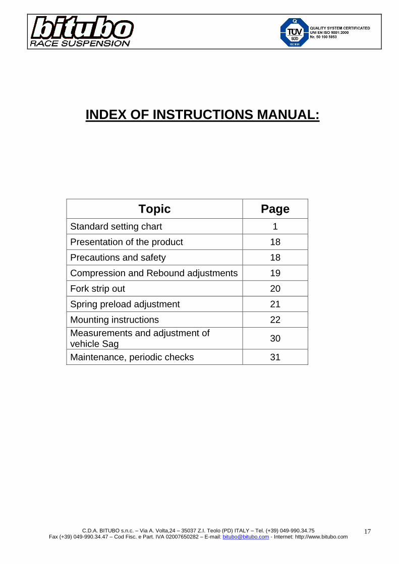
Topic Page Standard setting chart 1
Presentation of the product 18
Precautions and safety 18
Compression and Rebound adjustments 19
Fork strip out 20
Spring preload adjustment 21
Mounting instructions 22 Measurements and adjustment of vehicle Sag 30
Maintenance, periodic checks 31

C.D.A. BITUBO s.n.c. – Via A. Volta,24 – 35037 Z.I. Teolo (PD) ITALY – Tel. (+39) 049-990.34.75 Fax (+39) 049-990.34.47 – Cod Fisc. e Part. IVA 02007650282 – E-mail: [email protected] - Internet: http://www.bitubo.com
18
PRESENTATION OF THE PRODUCT Bitubo ECH Fork Cartridge is an High-Tech product made to offer the best performance, on the road as well as on the track, and is calibrated according to the parameters defined by Bitubo Technicians of Racing Division, developed with the experiences in the most prestigious Championships, such as WSBK,BSB,CIV,CEV,IDM,W Endurance. Below you can find the basic information on the way to set-up and personalize your Bitubo race cartridge ECH in order to achieve the best results and top performance.
PRECAUTIONS AND SAFETY
Before mounting the ECH Cartridge on the bike, take note of all values of sag and mounting position of the fork legs in the upper plate of the bike. Check that Bitubo base setting (length, spring preload and hydraulic adjustments) is accord ing to the data written on the chart at page 1.
To see the adjusters position, look at page 1 . Considering that during the production steps the cartridge is lubricated, you could find some trace of oil and grease on the cartridge. Together with these instructions, please find attached a Set-Up data sheet, used by the teams in order to take note of the modifications of the shock adjustments. Our Bitubo Service Centres are at your disposal in order to help you on looking for the best Set-Up for your needs (for contact your National Dealer, see the section “World Dealers” on our site www.bitubo.com) WARRANTY: Bitubo cannot be held responsible for any incorrect installation of the product or different as described in this handbook; neither for any modification in the product that is not describe or authorised in this manual which hasn’t been by Bitubo authorized in writing. Moreover Bitubo cannot be held responsible for the incorrect installation of the product. NOTE: The warranty for the product will be invalidated by incorrect installation or modifications carried out without Bitubo written authorisation. Bitubo cannot be held responsible for any damages to objects or injuries to people if the instructions of this handbook are not followed correctly or if the product is not fitted in a specialised workshop or by qualified personnel.

C.D.A. BITUBO s.n.c. – Via A. Volta,24 – 35037 Z.I. Teolo (PD) ITALY – Tel. (+39) 049-990.34.75 Fax (+39) 049-990.34.47 – Cod Fisc. e Part. IVA 02007650282 – E-mail: [email protected] - Internet: http://www.bitubo.com
19
SETTING MANUAL FOR ECH CARTRIDGE By convention, the clicks counting (referring to setting indicated in the schedule) starts with the adjusters at “full closed” or “0” position (in depth screwed adjuster)
WARNING: Forcing the adjuster after reaching the “0” position could damage the adjuster itself and compromise the good functioning of the shock absorber.
WARNING: On the upper cap you find the all the adjustments, hydraulic spring preload in both legs of the fork (adjuster knob with the red screw) and also the hydraulic compression and rebound adjustments. Both cartridges have separate and different hydraulic work: the cartridge with the yellow screw has an adjuster knob which is in charge to develop the hydraulic compression force. And the cartridge with the blue screw has an adjuster knob that develops the hydraulic rebound force. The leg where it is install the compression cartrid ge normally doesn’t have hydraulic rebound force, by the other way round for the rebound leg.
HOW TO ADJUST THE FORK CARTRIDGE
COMPRESSION
WARNING: no specific tools are necessary to operate with the adjuster knob. Please don’t force beyond the end turn limit of the adjuster. For rule and coherency with the XXF monoshock, the cartridge with the hydraulic compression will be install in the left fork leg of the bike (recognize by the yellow screw in the middle of the adjustment knob) It could cause a little confusion to some of the technicians who use Bitubo if the mount side is exchange, but there will not be any function variation of the bike fork. The adjustment range useful would be from position “0 (full close) to 24 clicks, but the margin of the device could allow around 30 total clicks. To increase the damping, turn clockwise the adjuster knob with yellow screw. To decrease the damping, turn it anticlockwise
REBOUND WARNING: no specific tools are necessary to operate with the adjuster knob. Please don’t force beyond the end turn limit of the adjuster. For rule and coherency with the XXF monoshock, the cartridge with the hydraulic rebound will be install in the right fork leg of the bike (recognize by the blue screw in the middle of the adjustment knob) It could cause a little confusion to some of the technicians who use Bitubo if the mount side is exchange, but there will not be any function variation of the bike fork. The adjustment range useful would be from position “0 (full close) to 24 clicks, but the margin of the device could allow around 30 total clicks.
To increase the damping, turn clockwise the adjuster knob with blue screw. To decrease the damping, turn it anticlockwise

C.D.A. BITUBO s.n.c. – Via A. Volta,24 – 35037 Z.I. Teolo (PD) ITALY – Tel. (+39) 049-990.34.75 Fax (+39) 049-990.34.47 – Cod Fisc. e Part. IVA 02007650282 – E-mail: [email protected] - Internet: http://www.bitubo.com
20
FORKS STRIP OUT ADJUSTMENT
The cartridges that have the final code ECH29 have the same length as the original ones (as they have an internal top out spring they can be stretch to the maximum as the bellow scheme) So, when they are installed the length of the fork will be the same as the original. If a cartridge with the end code ECHA9 there will be a different length to the original has to be install, the value “difference length from the original” has to be reported in the “base setting” chart, see page 1. Restore the correct front height (see picture below): The Q value measure is reported in the “base setting” chart, see page 1. Q = Orig. > The measure is as the original mounting (see the T echnical Manual of the vehicle) Q = Value (example:10mm) > position the fork legs to the suggest measure as i n the below scheme. The fork positioning values have been obtained by our Race Department and have been checked by coupling the ECH KIT with our rear shock absorber. If a different product is coupled, the vehicle might be unstable.
WARNING: The cycle measures of the bike are the result of long tests by the manufacturer and the Q measure for granting an easier handling and better stability keeping the safety needed. Variation of 2 or 3 mm give a big modification in the vehicle behavior.
A variation of the Q measure can change some important cycle measures prescribe by the Manufacturer of the Vehicle and can cause instability of the vehicle while it is running or parked (on the central stand or on the side stand) compromising the safety on riding and in use.
ESTENDERE CON FORZA = 30Kgf EXTEND WITH FORCE = 30Kgf
INTERASSE / LENGTH

C.D.A. BITUBO s.n.c. – Via A. Volta,24 – 35037 Z.I. Teolo (PD) ITALY – Tel. (+39) 049-990.34.75 Fax (+39) 049-990.34.47 – Cod Fisc. e Part. IVA 02007650282 – E-mail: [email protected] - Internet: http://www.bitubo.com
21
SPRING PRELOAD ADJUSTMENT
Spring preload range is 12 mm Each click of the adjuster (1/2 turn) equals 1 mm of preload of the spring To increase the value of the spring preload, turn by hand clockwise the adjuster knob. To decrease the preload value, turn the adjuster anti-clockwise. For better handling the preload adjusters, you can use the tool (cod. 09901000) included in the Cartridge Kit
The preload values are very important like the values of the forks strip out. The preload defines the height of the bike from the ground as well as the dynamic set-up on a bend, therefore also the angle values of the fork, the front, etc. which characterize the behaviour of the vehicle. Generally speaking, the best preload values are defined between 3 and 8 mm. To optimized the preload values, please read the chapter “Measurements and adjustment of the vehicle Sag”
WARNING: this kind of cartridge is provided by an internal top out spring. Verify the measures at completely extended suspension, not only by lifting the bike from the ground, but forcing the suspension in extension too, in order to compress totally the top out spring.
The spring preload is the pressure apply to the spring when it is installed in the cartridge.
PRELOAD=F-M
M F
MANOPOLA DI REGOLAZIONE DEL PRECARICO MOLLA PRELOAD SPRING ADJUSTER KNOB
ATTREZZO/TOOL cod. 09901000

C.D.A. BITUBO s.n.c. – Via A. Volta,24 – 35037 Z.I. Teolo (PD) ITALY – Tel. (+39) 049-990.34.75 Fax (+39) 049-990.34.47 – Cod Fisc. e Part. IVA 02007650282 – E-mail: [email protected] - Internet: http://www.bitubo.com
22
MOUNTING INSTRUCTIONS
WARINING: Bitubo doesn’t tighten the upper cap, nor any spa cer if present at the cartridges lower end when delivered, because they must be remo ve for the installation and then be tighten after mounting. Thanks to our racing experience with BE1 team in th e WSS championship, we improved the bike cornering by removing the 5 mm end-stroke bump er on each cartridge, such increasing the fork excursion of 5 mm and using all available stroke; for this reason, it is needed to pay the highest attention to remove the bumper and we r ecommend to do it just through an authorized Bitubo Service Centre. On using the fork, it is recommended to check caref ully the fork excursion and change, if necessary, the oil level in order not to reach the end of the excursion too fast.
1- Put the bike over a support that could permit to share the weight of both bike wheels to work safely
without the front wheel and forks. 2- Take out the Q measure see “the fork strip out adjustment” paragraph on page 5 and follow the
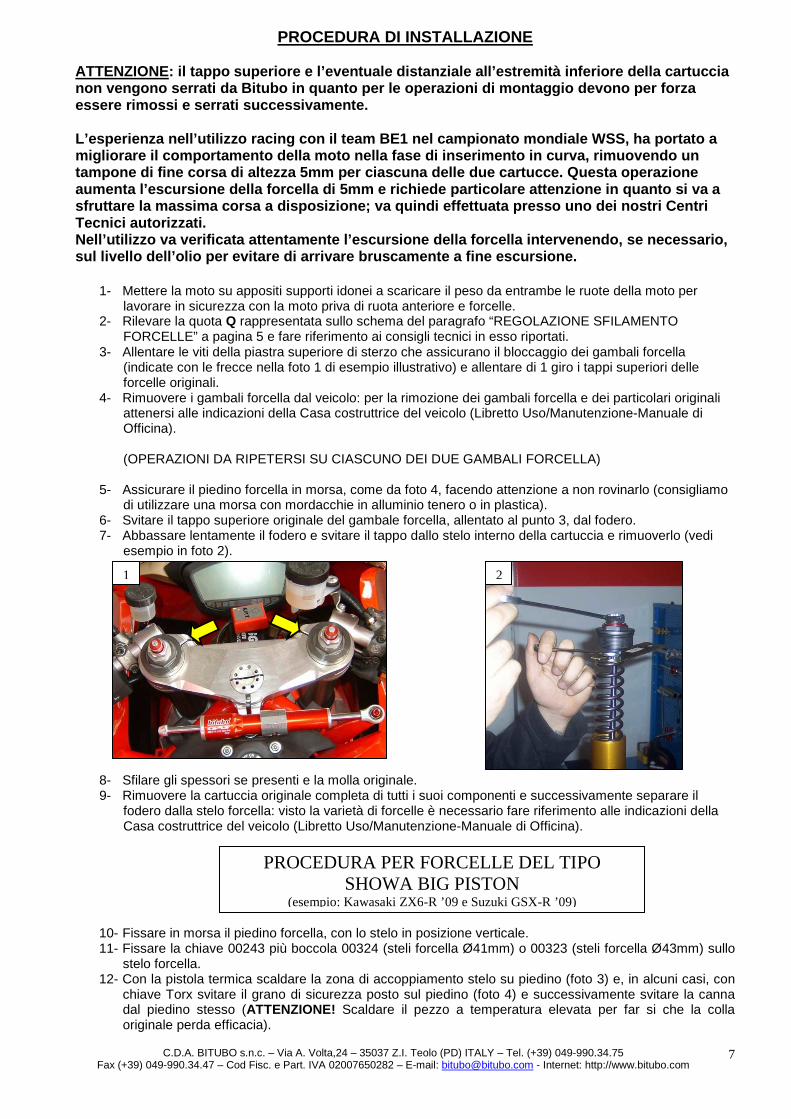
technical advises 3- Unscrew the lock screw of upper steering plate (see photo 1), and unscrew one turn the upper cap of
both fork legs. 4- Remove both fork legs from the vehicle: to remove it and the other original parts follow the Vehicle
Constructor Indications (Use/Service manual – Machine shop manual). (MAKE THE SAME PROCESS IN BOTH FORK LEGS)
5- Fix the outer tube of the fork leg in a vice paying attention not to scratch or deform it. 6- Unscrew from the outer tube the upper original cap of the fork leg. 7- Slowly lower the outer tube, unscrew and remove from the cartridge internal rod the upper cap (see the
example on photo 2).
8- Slip of the spacers (if present) and the original spring. 9- Take out the original cartridge with all its components and after separate the outer tube from the fork
rod: because there are too many kinds of forks we need to make from the Vehicle Constructor Indications (Use/Service manual – Machine shop manual).
10- Place the foot of the fork in the vice with the stem in a vertical position. 11- Attach the tool 00243 and bushing 00324 (fork stem Ø 41mm) or 00323 (fork stem Ø 43mm) to the fork
stem. 12- Use the heat gun to warm the area of coupling of the stem with the foot (photo 3) and eventually with
the Torx wrench to unscrew the safety nut on the foot (photo 4), then unscrew the pipe from the foot (ATTENTION: Heat the zone to an high temperature, so that the original glue loosens).
1
ONLY FOR SHOWA BIG PISTON FORK TYPE (example: Kawasaki ZX6-R ’09 onwards, and Suzuki GSX-R ’09 onwards
2

C.D.A. BITUBO s.n.c. – Via A. Volta,24 – 35037 Z.I. Teolo (PD) ITALY – Tel. (+39) 049-990.34.75 Fax (+39) 049-990.34.47 – Cod Fisc. e Part. IVA 02007650282 – E-mail: [email protected] - Internet: http://www.bitubo.com
23
13- Remove the adjustment of the pre-loading spring located into the fork foot, and remove all of its components. (photos 5-6-8)
14- Screw only the external ferrule “A” back into place with the relative screw “B”, on the foot of the fork. 15- Use an appropriate tool to slide off the original sealing O-ring located inside the foot, and eliminate the
original steel nut. (photo 7) 16- Clean all of the original parts carefully, and remove glue residues. 17- Remove the spacer “D”, which is screwed manually onto the cap of the lower cartridge “C” (and is not
tightened), from the lower attachment of the ECH Bitubo cartridge (photo 9). 18- Replace the original O-ring inside the foot and insert the “D” spacer in place of the original steel nut, so
that it lodges perfectly onto the bottom of the foot (the forcing of the spacer “D” into the passage of the O-ring must be felt) (photo 10).
A
B
A
3 4
5 6 7
8
C.D.A. BITUBO s.n.c. – Via A. Volta,24 – 35037 Z.I. Teolo (PD) ITALY – Tel. (+39) 049-990.34.75 Fax (+39) 049-990.34.47 – Cod Fisc. e Part. IVA 02007650282 – E-mail: [email protected] - Internet: http://www.bitubo.com
24
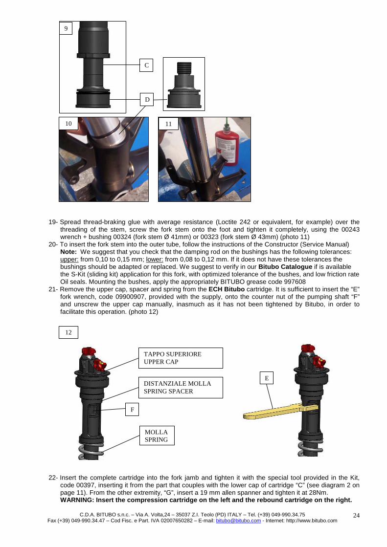
19- Spread thread-braking glue with average resistance (Loctite 242 or equivalent, for example) over the threading of the stem, screw the fork stem onto the foot and tighten it completely, using the 00243 wrench + bushing 00324 (fork stem Ø 41mm) or 00323 (fork stem Ø 43mm) (photo 11)
20- To insert the fork stem into the outer tube, follow the instructions of the Constructor (Service Manual) Note: We suggest that you check that the damping rod on the bushings has the following tolerances: upper: from 0,10 to 0,15 mm; lower: from 0,08 to 0,12 mm. If it does not have these tolerances the bushings should be adapted or replaced. We suggest to verify in our Bitubo Catalogue if is available the S-Kit (sliding kit) application for this fork, with optimized tolerance of the bushes, and low friction rate Oil seals. Mounting the bushes, apply the appropriately BITUBO grease code 997608
21- Remove the upper cap, spacer and spring from the ECH Bitubo cartridge. It is sufficient to insert the “E” fork wrench, code 09900907, provided with the supply, onto the counter nut of the pumping shaft “F” and unscrew the upper cap manually, inasmuch as it has not been tightened by Bitubo, in order to facilitate this operation. (photo 12)
22- Insert the complete cartridge into the fork jamb and tighten it with the special tool provided in the Kit, code 00397, inserting it from the part that couples with the lower cap of cartridge “C” (see diagram 2 on page 11). From the other extremity, “G”, insert a 19 mm allen spanner and tighten it at 28Nm. WARNING: Insert the compression cartridge on the left and th e rebound cartridge on the right.
C
D
E
F
TAPPO SUPERIORE UPPER CAP
DISTANZIALE MOLLA SPRING SPACER
MOLLA SPRING
9
10 11
12

C.D.A. BITUBO s.n.c. – Via A. Volta,24 – 35037 Z.I. Teolo (PD) ITALY – Tel. (+39) 049-990.34.75 Fax (+39) 049-990.34.47 – Cod Fisc. e Part. IVA 02007650282 – E-mail: [email protected] - Internet: http://www.bitubo.com
25
23- Bring both the lining and the pumping shaft into the maximum compression position in order to fill the oil up to the correct level: be careful to press the pumping shaft down manually, pushing it from the threaded extremity, without forcing it against the internal bar. Add Bitubo SAE 0W30 oil, code 997637, which is provided in the package, topping off to the level prescribed in the “base setting” table on page 1, from the border of the external lining. Perform several compression-extension movements of the external lining, to purge any air.
24- Check the level, again with the lining and pumping shaft in the maximum compression position and, if necessary, add oil.
25- Tighten counter nut “F” completely (photo 14). 26- Insert the spring and spacer removed at point 21. 27- Screw the cap on manually, until it strikes against the cartridge stem; ATTENTION:ENSURE THAT IT
IS TIGHT AGAINST THE STEM.
Note: to differentiate accurately extension cartridge from the one of rebound please see the image from page 1 where it is reported the external differences from both cartridges.
28- Bring the counter nut “F” near the cap and tighten it against the cap with fork wrench “E”, keeping the cap blocked with the wrench, code 00398, supplied (any commercial tool with a square ½ inch attachment can be inserted on the wrench). ATTENTION: Do not exceed a torque of 9.0 Nm.
29- Bring the fork lining towards the cartridge cap, screw the cap onto it until it is completely tight as in figure 14; fasten the lining in the vice, taking care to avoid ruining the surface and distorting it into an oval shape. Tighten the cap to 15 Nm.
30- Replace the fork legs on the bike, following the instructions contained in the Vehicle Manufacturer Manual: once tight the screws from the lower steering plate that lock the fork legs and before tight the relative screws of the upper steering plate (indicated with the arrow in picture 1 as example), tight the upper caps at 15Nm.
ESTREMITA’ INFERIORE CARTUCCIA LOWER CARTRIDGE END
C
G
13
F
ATTACCO QUADRO DA 1/2” SQUARE ATTACHMENT 1/2”
E
ATTREZZO/TOOL cod. 00398
FODERO OUTER TUBE

C.D.A. BITUBO s.n.c. – Via A. Volta,24 – 35037 Z.I. Teolo (PD) ITALY – Tel. (+39) 049-990.34.75 Fax (+39) 049-990.34.47 – Cod Fisc. e Part. IVA 02007650282 – E-mail: [email protected] - Internet: http://www.bitubo.com
26
CONTINUE FROM THE 8 POINT
31- To insert the fork stem into the outer tube, follow the instructions of the Constructor (Service Manual) Note: We suggest that you check that the damping rod on the bushings has the following tolerances: upper: from 0,10 to 0,15 mm; lower: from 0,08 to 0,12 mm. If it does not have these tolerances the bushings should be adapted or replaced. We suggest to verify in our Bitubo Catalogue if is available the S-Kit (sliding kit) application for this fork, with optimized tolerance of the bushes, and low friction rate Oil seals. Mounting the bushes, apply the appropriately BITUBO grease code 997608
32- Remove the upper cap, spacer and spring from the ECH Bitubo cartridge. It is sufficient to insert the “E” fork wrench, code 09900907, provided with the supply, onto the counter nut of the pumping shaft “F” and unscrew the upper cap manually, inasmuch as it has not been tightened by Bitubo, in order to facilitate this operation. (photo 15) ATTENTION: once the upper caps is remove do not man ipulate the adjustment knob
33- Most of the cartridge are presented as the scheme 1, to be more precise with the spacer “D” that is manually screw (without been tighten)over the inferior cap from the “C” cartridge disassemble the spacer and fix it to the fork foot as in scheme 1
34- If you had to follow the assembly shown in diagram 1, insert the complete cartridge inside the fork and attach it to the spacer just mounted. Insert a 19 mm Allen spanner into extremity „G“ and tighten it at 28Nm.
ATTENTION: Insert the compression cartridge on the left and th e rebound cartridge on the right.
PROCEDURE FOR TRADITIONAL FORKS
E
F
TAPPO SUPERIORE UPPER CAP
DISTANZIALE MOLLA SPRING SPACER
MOLLA SPRING
15

C.D.A. BITUBO s.n.c. – Via A. Volta,24 – 35037 Z.I. Teolo (PD) ITALY – Tel. (+39) 049-990.34.75 Fax (+39) 049-990.34.47 – Cod Fisc. e Part. IVA 02007650282 – E-mail: [email protected] - Internet: http://www.bitubo.com
27
D
C
VITE E RONDELLA ORIGINALI SERRARE CON COLLA BLOCCANTE TIPO LOCTITE 638 O
EQUIVALENTE 30Nm ORIGINAL SCREW AND WASHER
TIGHTEN WITH FIXED GLUE AS LOCTITE 638 OR SIMILAR 30Nm
SCHEMA 1 / 1 SCHEME Cartucce con distanziale inferiore
Cartridge with lower spacer
ATTREZZO/TOOL cod.00397
G

C.D.A. BITUBO s.n.c. – Via A. Volta,24 – 35037 Z.I. Teolo (PD) ITALY – Tel. (+39) 049-990.34.75 Fax (+39) 049-990.34.47 – Cod Fisc. e Part. IVA 02007650282 – E-mail: [email protected] - Internet: http://www.bitubo.com
28
35- In some cartdriges (like Yamaha R6 ’08-’10) is present the cap in the lower part “H” type without any
spacers: in these cases the cartdrige is fixed directly to the fork feet like in the scheme 2. In the low end “G” insert an allen key of 19mm and tight at 28Nm. ATTENTION: Insert the compression cartridge on the left and th e rebound cartridge on the right.
H
ATTREZZO/TOOL cod.00397
SCHEMA 2 / 2 SCHEME Cartucce senza distanziale inferiore Cartridge without the lower spacer

C.D.A. BITUBO s.n.c. – Via A. Volta,24 – 35037 Z.I. Teolo (PD) ITALY – Tel. (+39) 049-990.34.75 Fax (+39) 049-990.34.47 – Cod Fisc. e Part. IVA 02007650282 – E-mail: [email protected] - Internet: http://www.bitubo.com
29
36- Bring both the lining and the pumping shaft into the maximum compression position in order to fill the oil
up to the correct level: be careful to press the pumping shaft down manually, pushing it from the threaded extremity, without forcing it against the internal bar. Add Bitubo SAE 0W30 oil, code 997637, which is provided in the package, topping off to the level prescribed in the “base setting” table on page 1, from the border of the external lining. Perform several compression-extension movements of the external lining, to purge any air.
37- Check the level, again with the lining and pumping shaft in the maximum compression position and, if necessary, add oil.
38- Tighten counter nut “F” completely (photo 16). 39- Insert the spring and spacer removed at point 32. 40- Screw the cap on manually, until it strikes against the cartridge stem; ensure that it is tight against the
stem. ATTENTION: ENSURE THAT IT IS TIGHT AGAINST THE STEM . Note: to differentiate accurately extension cartridge from the one of rebound please see the image from page 1 where it is reported the external differences from both cartridges.
41- Bring the counter nut “F” near the cap and tighten it against the cap with fork wrench “E”, keeping the cap blocked with the wrench, code 00398, supplied (any commercial tool with a square ½ inch attachment can be inserted on the wrench). ATTENTION: Do not exceed a torque of 9.0 Nm.
42- Bring the fork lining towards the cartridge cap, screw the cap onto it until it is completely tight; fasten the lining in the vice, taking care to avoid ruining the surface and distorting it into an oval shape. Tighten the cap to 15 Nm.
43- Replace the fork legs on the bike, following the instructions contained in the Vehicle Manufacturer Manual: once tight the screws from the lower steering plate that lock the fork legs and before tight the relative screws of the upper steering plate (indicated with the arrow in picture 1 as example), tight the upper caps at 15Nm.
F
ATTACCO QUADRO DA 1/2” SQUARE ATTACHMENT 1/2”
E
ATTREZZO/TOOL cod. 00398
16
FODERO OUTER TUBE

C.D.A. BITUBO s.n.c. – Via A. Volta,24 – 35037 Z.I. Teolo (PD) ITALY – Tel. (+39) 049-990.34.75 Fax (+39) 049-990.34.47 – Cod Fisc. e Part. IVA 02007650282 – E-mail: [email protected] - Internet: http://www.bitubo.com
30
ADJUSTMENT AND MEASUREMENT OF SAG
1) Lift the bike (fork free from loading
and lifted tyre from the ground) and press the spring retainer forcing the full extension of the kinematic mechanism of the rear suspension. Follow the same procedure also on the fore-carriage.
2) Individuate two reference points on the vertical axe of the tyre pin: one on the centre, the other one fixed on the little frame under the seat of the bike. Both points shall be precise and well defined in order to make this operation again more and more times. Follow the same procedure on the fore-carriage.
3) Measure the distance between the two points Z1 and F1.
4) Place the bike to the ground with both
tyres, press slowly the suspension twice and leave it then be extended freely.
5) Measure the new distance between the two points Z2 and F2.
6) Z2-Z1 (static sag) shall be included between 5mm and 15mm for road replica bikes, between 10mm and 20mm for road and naked bikes, between 15 and 25mm for enduro tourism bikes; F2-F1 (static sag) shall be included between 25mm and 32mm for road and naked bikes; between 30mm and 40mm for enduro tourism bikes.
7) Make all measurements again having
the rider on the bike in position of riding.
8) Z3-Z1 (rider sag) shall be included
between 25mm and 30mm for road replica and naked bikes. For enduro and tourism bikes the value shall be included between 30mm and 40mm . F3-F1 (rider sag) shall be included between 35mm and 40mm for road race replica and naked bikes. For enduro tourism bikes the value should be included between 40mm and 50mm.
In order to decrease the value of static sag, you shall increase the spring preload adjusting; on the other hand, in order to increase the static sag, you shall decrease the spring preload. The ECH cartridge ensures great driveability of your vehicle, guaranteeing greater support in curves and faster manoeuvrability in changing directions, great grip during acceleration and braking, in addition to ensuring safety under various conditions of use. In order to take full advantage of the effectiveness, we advise you to improve the rear suspension as well, mounting our Racing XXF or Sport CLU shock absorbers. The ECH fork cartridge reaches its maximum performance mounting our Kit S, which increases the smoothness of the fork, an essential requirement for a High Performance Fork. Information is available at our Bitubo Technical Centres, or at the website www.bitubo.com

C.D.A. BITUBO s.n.c. – Via A. Volta,24 – 35037 Z.I. Teolo (PD) ITALY – Tel. (+39) 049-990.34.75 Fax (+39) 049-990.34.47 – Cod Fisc. e Part. IVA 02007650282 – E-mail: [email protected] - Internet: http://www.bitubo.com
31
MANINTENANCE OF THE FORK
Cleaning and lubricating your fork prevents its early wear and tear and increases its performances longer.
WARNING: On cleaning the bike, pay attention not to turn the water jet at high pressure directly to the oil fork seals and to the upper cartridge caps. WARNING: Clean the fork and the upper caps with not aggressive cleaner. Delete all residual rubber parts attaching the fork mainly on race use and on the moving parts.
Maintenance and periodic checks are recommended to be made by a Bitubo Service Centre (see list of official Service Centres and Worldwide importers in our website www.bitubo.com)
Yearly or after 10.000 km:
- Have your fork checked for proper operation at a Bitubo Technical Centre.
For road use, we recommend the service every 2 year s or 20.000 km For race use, we recommend the service every 12 hou rs for a perfect functioning and anyway not longer than 24 hours.
The shock contains Nitrogen gas in pressure.
WARNING: the warranty of the product stops if it is mounted wrongly or modified without written approval by Bitubo.
Bitubo cannot be held as responsible of damages to objects or injuries to people in case the instructions of this manual are not followed correctly or in case the product is not mounted by a specialized workshop and qualified persons.

C.D.A. BITUBO s.n.c. – Via A. Volta,24 – 35037 Z.I. Teolo (PD) ITALY – Tel. (+39) 049-990.34.75 Fax (+39) 049-990.34.47 – Cod Fisc. e Part. IVA 02007650282 – E-mail: [email protected] - Internet: http://www.bitubo.com
32
Set-up data BIKE N° Rider / Pilote
Date Country/ Pays Bike / Moto Team / Equipe
Track/ Circuit Temperature Temperature Weather
Météo Rider kg / Pilote kg
STD 1 2 3 4 5 6 7 8 9
Shock absorber
Matricola Serial No . N de serie
Schema Scheme Schéma
K molla/Spring rate / Ressort
Precarico Preload
Précontrainte
Estensione Rebound/Détente
Comp. High/Rapide
Comp. Low/Lente Interasse/ Length
Entraxe
Pressione Pressure Préssion
Front F
ork
Matricola Serial No . N de serie
Schema
Scheme/ Schéma Sfilamento
Slipping Longueur
Pressione Pressure Préssion
Estensione Rebound Détente
Compression Compréssion
K molla/Spring rate / Ressort
Precaric/ Preload Précontrainte
Livello olio Oil level
Niveau huile
Note/Notes


![[XLS] · Web viewDIESEL SIGME FS 30 ECOFREEZE COOLANT FG ECOPERMANENT fluido anticongelante pronto all' uso base propilenica, protezione -35 C F1 SUPERMOTOROIL FORK 10W FORK 15W FORK](https://static.fdocumenti.com/doc/165x107/5b1bd3ed7f8b9a2d258ef633/xls-web-viewdiesel-sigme-fs-30-ecofreeze-coolant-fg-ecopermanent-fluido-anticongelante.jpg)