CA651112*-07 CA661112*-07 CA661315*-07...
48
CA651112*-07 CA661112*-07 CA661315*-07 CA662112*-07 CA662132*-07 CA662432*-07 CA663112*-07 CA663432*-07 CA762402*-07 CA964TZM*3607 CA974TZMI4207 CC651112*-07 CC662112*-07 CC662132*-07 Manuale d’installazione e uso Installation and use manual Cucina Cooker
Transcript of CA651112*-07 CA661112*-07 CA661315*-07...

CA651112*-07
CA661112*-07
CA661315*-07
CA662112*-07
CA662132*-07
CA662432*-07
CA663112*-07
CA663432*-07
CA762402*-07
CA964TZM*3607
CA974TZMI4207
CC651112*-07
CC662112*-07
CC662132*-07
Manuale d’installazione e uso
Installation and use manual
Cucina
Cooker
2
Complimenti per aver acquistato un’apparecchiatura
Jollynox!
Questa è un’apparecchiatura di grande qualità in grado di accompagnarvi nel Vostro lavoro per lungo tempo in modo affidabile e sicuro fornendo presta-zioni di altissimo livello.
L’installazione e l’uso dell’apparecchiatura è semplice e immediato.
Vi invitiamo a leggere attentamente questo manuale: ciò permetterà un’ installazione e un utilizzo corretto che manterrà la Vostra apparecchiatura sempre per-fetta ed efficiente negli anni.
Per agevolare la lettura del manuale sono riportati i seguenti simboli:
Prescrizioni importanti per la sicurezza perso-nale e dell’apparecchiatura
Informazioni generali
Congratulations on purchasing a Jollynox ap-
pliance!
This safe and reliable high-quality appliance can
assist you in your work with long-lasting top-level
performance.
It also has the added advantage of being quick and
simple to install and easy to use.
Please read this manual carefully, as it provides im-
portant information for the correct installation and
use of the appliance which will ensure its long-term
efficiency.
The following symbols are used to assist you in reading
this manual:
Important rules for personal safety and the
safety of the appliance
General information
Il Costruttore si riserva di apportare ai propri prodotti e a questo manuale le modi!che che riterrà opportune senza obbligo di preavviso. I disegni, gli schemi di installazione e le tabelle contenuti all’in-terno del manuale sono da ritenersi indicativi ed esclusivamente a titolo d’informazione.
Gli impianti di allacciamento dell’immobile devono rispettare le normative nazionali vigenti.
É vietata la copia, la riproduzione parziale o totale dei conte-nuti e l’inoltro di questo manuale a terzi senza il permesso del Costruttore.
Questo apparecchio è conforme alle prescrizioni delle direttive comunitarie CEE 87/308 del 2.6.87 (recepita con D.M. del 13.4.89) sulla prevenzione ed eliminazione dei radiodisturbi, n. 89/336 sul-la compatibilità elettromagnetica e 73/23 sulla bassa tensione.Le istruzioni del presente libretto sono valide solamente per il Paese di destinazione.
The manufacturer reserves the right to make any changes
deemed suitable to the product without prior notice.
The drawings, installation diagrams and tables contained in this
manual are approximate and for informational purposes only.
The systems for connecting the appliance must comply with current
national regulations.
The partial or complete reproduction or photocopying of the contents
of this manual is forbidden, as well as the sending of this manual to
third parties, without the Manufacturer’s permission.
This appliance conforms to the EEC community guidelines 87/308
of 2.6.87 (acknowledged with Ministerial Decree dated 13/4/89) on
the prevention and elimination of radio interference, no. 89/336 on
electromagnetic compatibility, 73/23 on low voltage.
The instructions in this booklet are valid only for the country of
destination.
3
DESCRIZIONE PAG.
DATI TECNICI 4
INSTALLAZIONE 7
Avvertenze di sicurezza 7
Controllo e movimentazione 8
Smaltimento degli imballi 8
Scelta del luogo di installazione 9
Posizionamento 10
Collegamento elettrico 12
Collegamento gas 14
USO 18
Avvertenze di sicurezza 18
Prima di cominciare 22
Conoscere l’apparecchiatura 22
É bene sapere che 24
Qualche consiglio di cottura 25
Uso dell’apparecchiatura - PIANO COTTURA 26
Uso dell’apparecchiatura - FORNO 31
Possibili cause di insuccesso 40
Accessori 41
MANUTENZIONE 42
Avvertenze di sicurezza 42
Manutenzione ordinaria 43
Pulizia 43
Sostituzione lampadina 46
Periodi di inattività 46
Smaltimento a #ne vita 47
Assistenza post-vendita 47
INDICE INDEX
DESCRIPTION PAGE
TECHNICAL DATA 4
INSTALLATION 7
Safety warnings 7
Checks and handling 8
Disposal of the packaging 8
Installation site choice 9
Positioning 10
Connection to the power mains 12
Gas connection 14
USAGE 18
Safety warnings 18
Before starting 22
Understanding the appliance 22
Useful information 24
Some cooking suggestions 25
Using the appliance - HOB 26
Using the appliance - OVEN 31
Troubleshooting 40
Accessories 41
MAINTENANCE 42
Safety warnings 42
Routine maintenance 43
Cleaning 43
Lamp replacement 46
Periods of inactivity 46
End-of-life disposal 47
After-sales service 47
4
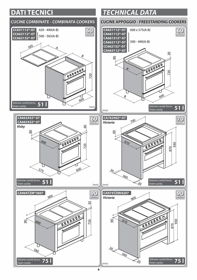
DATI TECNICI TECHNICAL DATA
6060
[mm]
6060
[mm]
[mm]
7070
90909090
[mm]
[mm]
Volume cavità forno
Oven cavity
CUCINE COMBINATE - COMBINATA COOKERSCUCINE COMBINATE - COMBINATA COOKERS CUCINE APPOGGIO - FREESTANDING COOKERSCUCINE APPOGGIO - FREESTANDING COOKERS
Volume cavità forno
Oven cavity
Volume cavità forno
Oven cavity
Volume cavità forno
Oven cavityVolume cavità forno
Oven cavity
600
A
90
72
03
0
B
87
0
560
610
60
700
30
20
93
08
70
560
61060
900
30
20
93
0
72
03
0
580
60090
900
600575
600
80
72
04
0
[mm]
Volume cavità forno
Oven cavity 51 l51 l51 l51 l
51 l51 l51 l
75 l75 l75 l75 l
500 - 565(A-B)
500 - 490(A-B)
600 x 575(A-B)420 - 490(A-B)CC651112*-07CC662112*-07CC662132*-07
CA651112*-07CA661112*-07CA661315*-07CA662112*-07CC662132*-07CA663112*-07
CA662432*-07CA663432*-07
CA964TZM*3607 CA974TZMI4207
CA762402*-07
6060
600
72
0
B
585 A
Victoria
Victoria
Vicky

5
Dati tecnici FORNO Technical data - OVEN
Tensione Voltage V 220-230
Frequenza Frequency Hz 50 - 60
Potenza Power
Totale assorbita Total power absorbed
GAS GAS kW 1,4
AA En
erg
y cl
ass BB STATICO AA E
ner
gy
clas
s BB STATIC kW 2,2
En
erg
y cl
ass AA MULTISETTE
En
erg
y cl
ass AA MULTISEVEN kW 2,3
En
erg
y cl
ass AA MULTIFUNZIONE (90)
En
erg
y cl
ass AA MULTIFUNCTION (90) kW 2,8
Resistenza superiore Upper heating element W 900
Resistenza grill Grill heating element W 1400
Resistenza inferiore Lower heating element W 1300
Potenza bruciatore forno a gas Gas oven burner power kW 2,5
Motoventilatore Motor fan W 30
Tangenziale Tangential W 30
Lampada Light W 15
Programmatore digitale Digital programmer W 3
Motore girarrosto Rotisserie motor W 4
Tipo cavo Cable type H05V2V2-F
Sezione cavo Cable section vedi fig. 10see fig. 10
Lunghezza cavo Cable length cm 90
Dotazioni Equipment
Padella leccarda Drip tray n° 1
Griglia Rack n° 2
Insulating
class11
L=90cm
Dati tecnici PIANO Technical data - HOB
Tensione Voltage V 220-230
Frequenza Frequency Hz 50 - 60
Potenza bruciatori Burner power
ausiliario auxiliary kW 1
semirapido semi- rapid kW 1,75
rapido rapid kW 3
tripla corona triple ring kW 3,3
tripla corona triple ring kW 3,6
Potenza piastre Hotplate power
ø 110 ø 110 kW 1
ø 145 ø 145 kW 1,5
ø 180 ø 180 kW 2

6
TABELLA UGELLI NOZZLE TABLE
Bruciatore
Burner
Tipo gas
Gas type
Pressione
d’esercizio
Applied
pressure
Portata
Capacity
ø Ugelli
1/100 mm
ø Nozzles
1/100 mm
Portata
nominale
Nominal
capacity
Portata
ridotta
Reduced
capacity
AusiliarioAuxiliary
G30G31G30G31G20G25
30 mbar37 mbar50 mbar50 mbar20 mbar25 mbar
g/h 73g/h 73g/h 73g/h 73l/h 94
l/h 110
505043437172
kW 1kW 1kW 1kW 1kW 1kW 1
kW 0.45kW 0.45kW 0.45kW 0.45kW 0.45kW 0.45
SemirapidoSemi- rapid
G30G31G30G31G20G25
30 mbar37 mbar50 mbar50 mbar20 mbar25 mbar
g/h 127g/h 127g/h 127g/h 127l/h 158l/h 165
656558589694
kW 1.75kW 1.75kW 1.75kW 1.75kW 1.75kW 1.75
kW 0.45kW 0.45kW 0.45kW 0.45kW 0.45kW 0.45
RapidoRapid
G30G31G30G31G20G25
30 mbar37 mbar50 mbar50 mbar20 mbar25 mbar
g/h 218g/h 218g/h 218g/h 218l/h 270l/h 292
85857575
115121
kW 3kW 3kW 3kW 3kW 3kW 3
kW 0.85kW 0.85kW 0.85kW 0.85kW 0.85kW 0.85
Tripla coronaTriple ring3,3 kW
G30G31G30G31G20G25
30 mbar37 mbar50 mbar50 mbar20 mbar25 mbar
g/h 240g/h 240g/h 240g/h 240l/h 328l/h 323
93937373
124130
kW 3.3kW 3.3kW 3.3kW 3.3kW 3.3kW 3.3
kW 1.40kW 1.40kW 1.40kW 1.40kW 1.40kW 1.40
Tripla coronaTriple ring3,6 kW
G30G31G30G31G20G25
30 mbar37 mbar50 mbar50 mbar20 mbar25 mbar
g/h 262g/h 262g/h 262g/h 262l/h 340l/h 396
96967676
138138
kW 3.6kW 3.6kW 3.6kW 3.6kW 3.6kW 3.6
kW 1.40kW 1.40kW 1.40kW 1.40kW 1.40kW 1.40
FornoOven
G30G31G20
30 mbar37 mbar20 mbar
g/h 181g/h 181l/h 238
8080
109
kW 2.5kW 2.5kW 2.5
kW 0.60kW 0.60kW 0.60

7
SAFETY WARNINGS
Read this instruction booklet carefully before instal-
lation and/or use of the appliance and keep it handy
so that all the users can consult it; if you transfer or sell
the appliance, please ensure that you give this booklet
to the new user so that he can be informed about its
installation, use and safety rules.
The installation and any interventions on the
appliance (extraordinary maintenance, etc.) must be
carried out by qualified personnel only, as specified
in this booklet.
The connection systems and installation rooms must
be suitable and satisfy the safety standards in force in
the country of use (protective isolating switch, earthing
system, equipotential system, etc.).
The manufacturer will not be held liable if the above
requirements are not satisfied.
During installation, maintenance or repair work,
always switch off the main electrical switch and remove
the connection plug from the socket.
INSTALLAZIONE INSTALLATION
AVVERTENZE DI SICUREZZA
Leggere attentamente questo libretto di istruzioni
prima dell’installazione e/o dell’uso dell’appa-
recchiatura e conservarlo in un luogo accessibile a tutti gli utilizzatori per consultazioni future; in caso di cessione o vendita dell’apparecchiatura assicurarsi di consegnare al nuovo utente anche questo libretto al fine di conoscerne l’installazione, l’uso e le prescrizioni di sicurezza.
L’installazione e gli interventi sulle apparec-chiature (manutenzione straordinaria, ecc..) vanno eseguiti solo da personale qualificato secondo quanto specificato nel presente libretto. Gli impianti di allacciamento e i locali di installazione devono essere idonei e rispondere alle norme di sicurezza in vigore nel Paese di utilizzo (interruttore di protezione e separazione, impianto di terra, equi-potenziale, ecc.).Il Costruttore non si ritiene responsabile qualora non venga rispettato quanto sopra descritto.
Durante le operazioni di installazione, manutenzione o riparazione spegnere sempre l’in-terruttore elettrico principale e staccare la spina di collegamento.

8
CHECKS AND HANDLING
After having unpacked the appliance and removed all
the packing materials and protective films from the sur-
faces, check for any anomalies: if you find an anomaly,
do not proceed with the installation but contact your
retailer within 8 days, reporting the data provided on
the appliance’s data plate and describing the problems
you found (fig. 1).
Caution! Do not leave the packing materials (plastic
bags, polystyrene, etc.) unattended, as they are a
potential hazard for children and animals (danger
of suffocation).
Move the appliance to the installation location by lifting
it using the appropriate means (fig. 1) and adopting all
the precautions necessary to prevent damage to the
appliance, people, animals and property.
DISPOSAL OF THE PACKAGING
Caution! Dispose of the packaging in compliance
with current regulations in the country where the
appliance is installed.
Package composition:
- cardboard
- polyethylene/ polypropylene: outer packaging film,
instructions bag
- expanded polystyrene: impact protections.
CONTROLLO E MOVIMENTAZIONE
Dopo aver disimballato l’apparecchiatura rimuovendo tutti i materiali di imballo e le pellicole a protezione delle superfici, controllare se si notano anomalie evidenti: in caso affermativo, non procedere all’in-stallazione e rivolgersi al Rivenditore entro 8 giorni, comunicando i dati riportati nella targa matricola dell’apparecchiatura ed i problemi riscontrati (fig. 1). Attenzione! Non lasciare incustodito il materiale
utilizzato per l’imballo (sacchetti, polistirolo, ecc...)
perché potenzialmente pericoloso per bambini e
animali (pericolo di soffocamento).
Trasportare l’apparecchiatura sul luogo dell’instal-lazione sollevandola con un mezzo idoneo (fig. 1) e adottando tutte le precauzioni necessarie per non arrecare danni all’apparecchiatura stessa, a persone, animali e cose.
1
SMALTIMENTO DEGLI IMBALLI
Attenzione! Smaltire gli imballi in ottemperanza
alle normative vigenti nel Paese di installazione.
Composizione imballo:- cartone- polietilene/ polipropilene: pellicola esterna imballo,
sacchetto istruzioni- polistirolo espanso: protezioni antiurto.
9
SCELTA DEL LUOGO DI INSTALLAZIONE
Caratteristiche del locale di installazione Le apparecchiature devono essere posizionate in locali interni idonei allo scopo con temperatura max. 25°C e umidità max. 60%; essi devono rispondere alle norme di sicurezza in vigore nel Paese di utilizzo (interruttore di protezione e separazione, impianto di terra, equipotenziale, ecc.). Le apparecchiature non sono adatte all’installazione all’aperto, esposte agli agenti atmosferici o alle intemperie. Le cucine combinate devono essere montate su mobili il cui materiale sia resistente al calore (120°C).
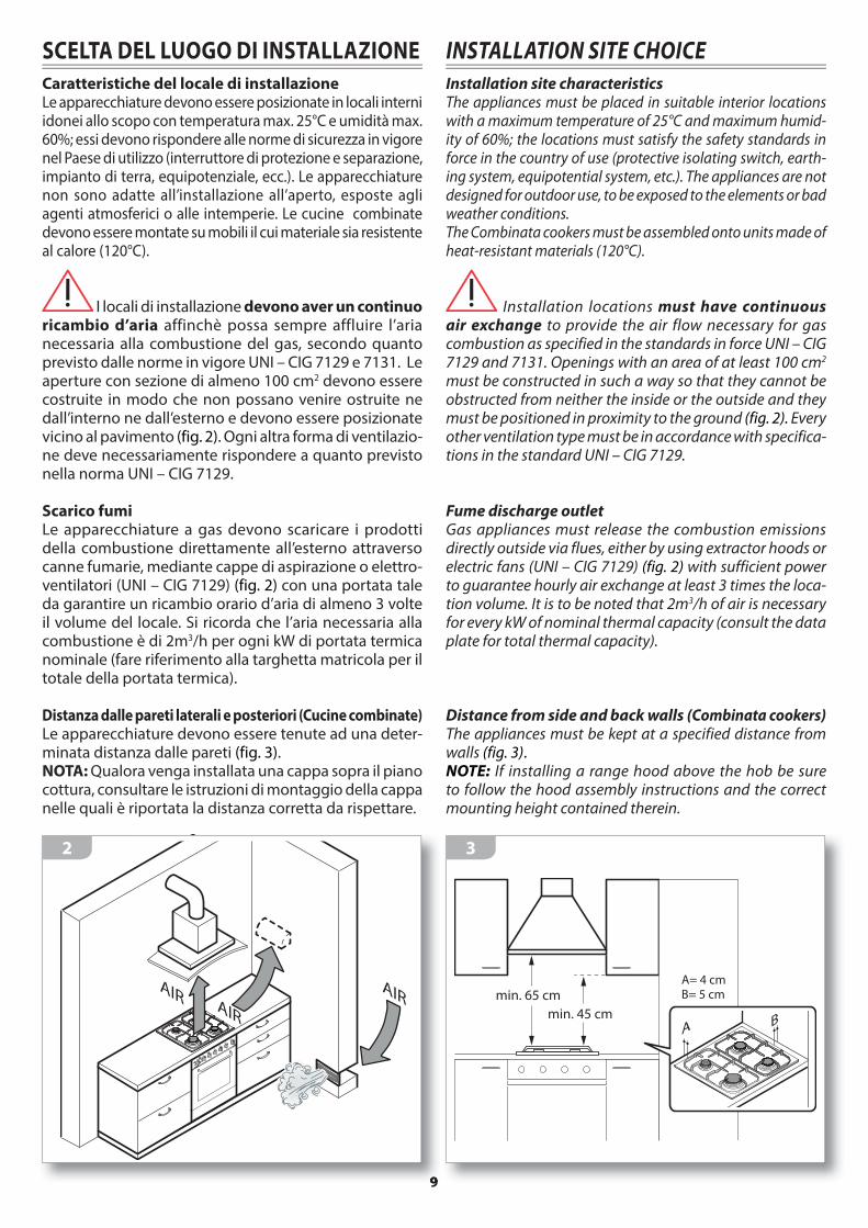
I locali di installazione devono aver un continuo ricambio d’aria affinchè possa sempre affluire l’aria necessaria alla combustione del gas, secondo quanto previsto dalle norme in vigore UNI – CIG 7129 e 7131. Le aperture con sezione di almeno 100 cm2 devono essere costruite in modo che non possano venire ostruite ne dall’interno ne dall’esterno e devono essere posizionate vicino al pavimento (fig. 2). Ogni altra forma di ventilazio-ne deve necessariamente rispondere a quanto previsto nella norma UNI – CIG 7129.
Scarico fumi Le apparecchiature a gas devono scaricare i prodotti della combustione direttamente all’esterno attraverso canne fumarie, mediante cappe di aspirazione o elettro-ventilatori (UNI – CIG 7129) (fig. 2) con una portata tale da garantire un ricambio orario d’aria di almeno 3 volte il volume del locale. Si ricorda che l’aria necessaria alla combustione è di 2m3/h per ogni kW di portata termica nominale (fare riferimento alla targhetta matricola per il totale della portata termica).
Distanza dalle pareti laterali e posteriori (Cucine combinate)Le apparecchiature devono essere tenute ad una deter-minata distanza dalle pareti (fig. 3). NOTA: Qualora venga installata una cappa sopra il piano cottura, consultare le istruzioni di montaggio della cappa nelle quali è riportata la distanza corretta da rispettare.
AIRAIR
AIR
2
INSTALLATION SITE CHOICE
Installation site characteristics The appliances must be placed in suitable interior locations with a maximum temperature of 25°C and maximum humid-ity of 60%; the locations must satisfy the safety standards in force in the country of use (protective isolating switch, earth-ing system, equipotential system, etc.). The appliances are not designed for outdoor use, to be exposed to the elements or bad weather conditions. The Combinata cookers must be assembled onto units made of heat-resistant materials (120°C).
Installation locations must have continuous air exchange to provide the air flow necessary for gas combustion as specified in the standards in force UNI – CIG 7129 and 7131. Openings with an area of at least 100 cm2 must be constructed in such a way so that they cannot be obstructed from neither the inside or the outside and they must be positioned in proximity to the ground (fig. 2). Every other ventilation type must be in accordance with specifica-tions in the standard UNI – CIG 7129.
Fume discharge outlet Gas appliances must release the combustion emissions directly outside via flues, either by using extractor hoods or electric fans (UNI – CIG 7129) (fig. 2) with sufficient power to guarantee hourly air exchange at least 3 times the loca-tion volume. It is to be noted that 2m3/h of air is necessary for every kW of nominal thermal capacity (consult the data plate for total thermal capacity).
Distance from side and back walls (Combinata cookers)The appliances must be kept at a specified distance from walls (fig. 3). NOTE: If installing a range hood above the hob be sure to follow the hood assembly instructions and the correct mounting height contained therein.
min. 65 cm
min. 45 cm
A= 4 cmB= 5 cm
AB
3

10
POSIZIONAMENTO
Libera installazione CLASSE 1
Tra due mobili CLASSE 2/1
Combinata CLASSE 2/2
Alcuni modelli hanno la possibilità di montare dei
piedini di appoggio acquistabili separatamente;
ruotandoli è possibile regolare l’altezza della cucina
in base alle proprie esigenze (fig. 4).
Al termine dell’ operazione verificare sempre
la perfetta planarità della cucina (fig. 5).
4
Cucine appoggio
Posizionare la cucina nel luogo scelto per l’installazione.
Se la cucina è posta su un piedistallo, si devono adot-
tare misure idonee per evitare che l’apparecchiatura
scivoli dal piedistallo stesso.
Cucine combinate (fig. 7)
1-2) Staccare il piano dalla cucina svitando le 4 viti la-
terali e le 8 viti che tengono in posizione i bruciatori.
3) Abbassare i traversini con le coppe agendo sulle
viti metriche.
4) Posizionare la cucina nel vano predisposto sotto al
piano e riportare i traversini con le coppe all’altezza
originaria.
5) Rimontare il piano avvitando le 4 viti laterali e le 8
di fissaggio dei bruciatori.
6
POSITIONING
Freestanding CLASS 1Between the forniture CLASS 2/1
Built-in CLASS 2/2
Some models may be fitted with support feet, which may be purchased separately; by rotating them it is possible to adjust the height of the cooker based upon specific requirements (fig. 4).
At the end of this operation, always check the
perfect planarity of the cooker (fig. 5).
5
Freestanding cookersPosition the cooker within the selected installation site.If the cooker is placed on a pedestal, suitable means must be adopted to avoid that .the appliance slides off the pedestal itself.
Combinata cookers (fig. 7)
1-2) Remove the hob from the cooker by unscrewing the 4 side
screws and the 8 screws which keep the burners in place.
3) Lower the cross-bars with holders by acting upon the
metric screws.
4) Position the cooker in the housing under the hob
and bring the cross-bars with holders back to their
original height.
5) Replace the hob by screwing the 4 side screws and 8
burner fixing screws.
top 30/40
top 30/40
400 560
35
585x42
0
480 560
60
585x50
0

11
8
Si consiglia di installare l’apparecchiatura a una
distanza da frigoriferi e congelatori tale che il calore
non pregiudichi il buon funzionamento di questi
ultimi (fig. 8).
It is recommended that you install the appliance far
from refrigerators and freezers so that the heat produced
does not compromise the good operation of these ap-
pliances (fig. 8).
7
x4
x4
x8
x8
1
2
4
6
7
5
3

12
CONNECTION TO THE POWER MAINS
Before making the connection, make certain that the voltage and frequency indicated on the data plate match those of the power supply system.The oven is supplied with a 90 cm-long power cord (H05V2V2-F) (fig. 9A).Connect the cable directly to the electricity supply (fig. 9B), which must be made by an authorized person in ac-cordance with current regulations in the country where the appliance is installed. The installation must include a means for disconnection from the supply having an air gap contact separation in all active conductors that allows complete disconnection in category III overvolt-age condictions. The isolating switch should be sized according to the load on the data label and should comply with current regulations. If the supply cord is damaged , it must be replaced by the manufacturer or its service agent or a similarty qualified person in order to avoid hazard.
The isolating switch must be located in a position which is accessible even after the appliance is in-stalled.If the appliance is installed together with a hob, the connection of the two appliances must be independ-ent for electrical safety reasons.
The power cord must NOT:- be crushed or rolled up;- come into contact with any type of liquid, sharp or hot
objects or corrosive substances; - reach, at any point, a temperature which is 50°C higher
than the room temperature;- be replaced with a different type of cable (see “TECHNICAL
DATA” on page 4) or with a cable which is not up to standard;
- be lengthened with extensions.
COLLEGAMENTO ELETTRICO
Prima dell’allacciamento accertarsi che la tensione e la frequenza riportate sulla targhetta caratteristiche corrispondano a quelle dell’impian-to di alimentazione.Il forno viene fornito già provvisto di un cavo di ali-mentazione (H05V2V2-F) lungo 90 cm sul quale dovrà essere installata una spina che sopporti i 16 A (fig. 9A).In alternativa è possibile collegare il cavo direttamente alla rete di distribuzione (fig. 9B): l’operazione deve essere fatta da una persona autorizzata in conformi-tà alla normativa vigente nel Paese di installazione. L’impianto deve prevedere un dispositivo che assicuri la disconnessione dalla rete con una distanza tra i contatti che consenta la disconnessione completa nelle condizioni della categoria di sovratensione III. L’interruttore deve essere dimensionato in funzione del carico sulla targhetta matricola e deve essere conforme alle normative vigenti. Se il cavo di alimentazione è danneggiato esso deve essere sostituito dal Costruttore o dal suo servizio di Assistenza Tecnica o comunque da una persona qua-lificata similare, in modo da prevenire ogni rischio.Sia la presa di corrente che l’interruttore onnipolare devono essere a norma e collocati in posizione ac-cessibile anche con l’apparecchiatura incassata.Se l’apparecchiatura viene inserita in abbinamento a un piano cottura, l’allacciamento delle due appa-recchiature deve essere indipendente per motivi di sicurezza elettrica.
Il cavo di alimentazione NON deve:
- essere schiacciato o arrotolato su se stesso;
- entrare in contatto con liquidi di qualsiasi tipo,
oggetti taglienti o caldi e sostanze corrosive;
- raggiungere in nessun punto una temperatura che
superi di 50°C la temperatura ambiente;
- essere sostituito con uno di tipo diverso (vedi “DATI
TECNICI” a pag. 4) o non a norma;
- essere allungato con prolunghe.
9
H05V2V2-F3x1,5mm2
90 cm
16A
Mod.Art.N°
...V ...Hz ...Kw
Questo apparecchio deve essere installato conformemente
alle norme in vigore. Consultare il libretto istruzioni prima
di installare e usare l’apparecchio
F.lli Barazza S.r.l MADE IN ITALY
9A
9B

13
SOSTITUZIONE DEL CAVO DI ALIMENTAZIONE
In caso di necessità, il cavo di alimentazio-
ne può essere sostituito con uno di tipo identico
(vedi “DATI TECNICI” a pag. 4) in ottemperanza
alle normative vigenti nel Paese di installazione.
Se l’apparecchiatura è già collegata,
staccarla dall’alimentazione elettrica e gas (se
prevista).
Per accedere ai collegamenti elettrici, togliere il coper-
chietto della morsettiera e far leva sul gancio (fig. 10).
Staccare il vecchio cavo dai morsetti e rimuoverlo;
collegare il nuovo cavo (unicamente di tipo H05V2V2-
F) nei rispettivi morsetti, N - L - Terra.
Bloccare il nuovo cavo con l’apposito passacavo
e richiudere la morsettiera riposizionando il suo
coperchio.
230V ~cavo 3x4 mm²
400V ~ 2N cavo 4x2.5 mm²
400V ~ 3N cavo 5x2.5 mm²
cavo 3x1.5 mm²
1
2
3
N
L
N
T
4
1
2
3
NN
T
L3
L1
L2
4
1
2
3
N
L
N
T
4L
2
N
T
1L
10
POWER CORD REPLACEMENT
If necessary, the power cord can be replaced
with an identical type (see “TECHNICAL DATA” on
page 4) in compliance with current regulations
in the country where the appliance is installed.
If the appliance is already connected,
disconnect the electrical and gas power (where
present).
To access the electrical connections, remove the cover
from the terminal board and act on the hook (fig. 10).
Disconnect the old cord from the terminals and remove
it; connect the new cord (only the H05V2V2-F type) into
the respective terminals N - L - Earth.
Cover the new cord with the appropriate cord holder and
re-close the terminal, replacing its cover.
Le apparecchiature con piano elettrico sono predisposte per l’allacciamento ad una linea dome-stica con tensione 220V monofase, è tuttavia possibile adattare l’apparecchiatura ad una diversa tensione secondo quanto riportato nello schema della figura soprastante.
Appliances with electric hob are predisposed for connection to a domestic single-phase power supply of 220 V; you can adapt the appliance to different a voltage value by following the instruction provided in the diagram of the figure above.
14
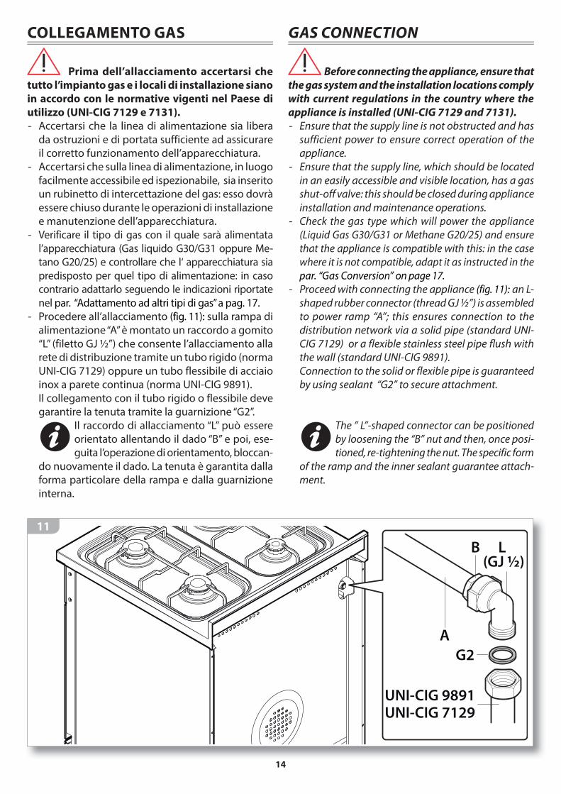
COLLEGAMENTO GAS
Prima dell’allacciamento accertarsi che
tutto l’impianto gas e i locali di installazione siano
in accordo con le normative vigenti nel Paese di
utilizzo (UNI-CIG 7129 e 7131).
- Accertarsi che la linea di alimentazione sia libera
da ostruzioni e di portata sufficiente ad assicurare
il corretto funzionamento dell’apparecchiatura.
- Accertarsi che sulla linea di alimentazione, in luogo
facilmente accessibile ed ispezionabile, sia inserito
un rubinetto di intercettazione del gas: esso dovrà
essere chiuso durante le operazioni di installazione
e manutenzione dell’apparecchiatura.
- Verificare il tipo di gas con il quale sarà alimentata
l’apparecchiatura (Gas liquido G30/G31 oppure Me-
tano G20/25) e controllare che l‘ apparecchiatura sia
predisposto per quel tipo di alimentazione: in caso
contrario adattarlo seguendo le indicazioni riportate
nel par. “Adattamento ad altri tipi di gas” a pag. 17.
- Procedere all’allacciamento (fig. 11): sulla rampa di
alimentazione “A” è montato un raccordo a gomito
“L” (filetto GJ ½”) che consente l’allacciamento alla
rete di distribuzione tramite un tubo rigido (norma
UNI-CIG 7129) oppure un tubo flessibile di acciaio
inox a parete continua (norma UNI-CIG 9891).
Il collegamento con il tubo rigido o flessibile deve
garantire la tenuta tramite la guarnizione “G2”.
Il raccordo di allacciamento “L” può essere
orientato allentando il dado “B” e poi, ese-
guita l’operazione di orientamento, bloccan-
do nuovamente il dado. La tenuta è garantita dalla
forma particolare della rampa e dalla guarnizione
interna.
11
GAS CONNECTION
Before connecting the appliance, ensure that
the gas system and the installation locations comply
with current regulations in the country where the
appliance is installed (UNI-CIG 7129 and 7131).
- Ensure that the supply line is not obstructed and has
sufficient power to ensure correct operation of the
appliance.
- Ensure that the supply line, which should be located
in an easily accessible and visible location, has a gas
shut-off valve: this should be closed during appliance
installation and maintenance operations.
- Check the gas type which will power the appliance
(Liquid Gas G30/G31 or Methane G20/25) and ensure
that the appliance is compatible with this: in the case
where it is not compatible, adapt it as instructed in the
par. “Gas Conversion” on page 17.
- Proceed with connecting the appliance (fig. 11): an L-
shaped rubber connector (thread GJ ½”) is assembled
to power ramp “A”; this ensures connection to the
distribution network via a solid pipe (standard UNI-
CIG 7129) or a flexible stainless steel pipe flush with
the wall (standard UNI-CIG 9891).
Connection to the solid or flexible pipe is guaranteed
by using sealant “G2” to secure attachment.
The ” L”-shaped connector can be positioned
by loosening the “B” nut and then, once posi-
tioned, re-tightening the nut. The specific form
of the ramp and the inner sealant guarantee attach-
ment.
A
L (GJ ½)
B
G2
UNI-CIG 9891
UNI-CIG 7129

15
Qualora la pressione del gas sia poco stabile,
installare a monte dell’apparecchiatura un
regolatore di pressione del gas (se l’apparec-
chiatura deve funzionare a gas liquido (G30 o G31),
utilizzare esclusivamente un regolatore di pressio-
ne conforme alla norma UNI-CIG 7432 (30 mbar).
Ad installazione ultimata, controllare la
perfetta tenuta di tutti i raccordi utilizzando una
soluzione di acqua e sapone, NON fiamme libere!
Ad installazione ultimata, provate ad ac-
cendere tutti i bruciatori (consultare cap. “PIANO A
GAS - Uso dei bruciatori”) e verificate che la fiamma
sia regolare e stabile, eventualmente procedere
come indicato nel par. “Regolazione del minimo”
a pag. 16.
Ultimata la regolazione, si prega di istruire l’utente
sul corretto modo di utilizzo dell’apparecchiatura. Nel
caso in cui l’apparecchio non funzioni correttamente
dopo tutti i controlli effettuati, contattare il rivenditore
autorizzato di zona.
If the gas pressure is unstable and it runs on
liquid gas (G30 or G31), install, above the appli-
ance, a gas pressure regulator; only use a gas
pressure regulator which complies with the standard
UNI-CIG 7432 (30 mbar).
Before Leaving: Check all connections for
gas leaks with soap and water. DO NOT use a naked
flame for detecting leaks.
Before Leaving: Ignite all burners to ensure
correct operation of gas valves, burners and ignition
(see chapter “GAS HOB - Using the burners”). Turn
gas taps to low flame position and observe stability
of the flame, regulating the minimum if necessary
(see “Regulating the minimum” on page 16).
When satisfied with the hotplate, please instruct the
user on the correct method of operation. In case the
appliance fails to operate correctly after all checks have
been carried out, refer to the authorised service provider
in your area.
Problema: Soluzione
Il flusso del gas
sembra irregolare
• Controllare che il rubinetto
del gas sia aperto completa-
mente.
• Controllare che la rete di
allacciamento abbia portata
adeguata.
• Controllare che gli sparti-
fiamma e i bruciatori siano
posizionati correttamente e
siano liberi da ostruzioni.
• Controllare che gli ugelli
siano adatti al tipo di gas
utilizzato.
• Controllare la corretta taratu-
ra del regolatore di pressione
se presente.
• Controllare il tubo di alimen-
tazione gas (tubo ostruito,
tubo piegato/schiacciato,
tubo eccessivamente lungo,
tubo inadatto, ecc...).
Problem: Solution
The gas flow seems
irregular
• Check that the gas tap is fully
open.
• Check that the connection net-
work has a sufficient supply.
• Check that the flame distribu-
tors and the burners are cor-
rectly positioned and that they
are not obstructed.
• Check that the nozzles are
suitable for the gas type used.
• Check that the pressure regu-
lator is correctly calibrated.
• Check the gas supply pipe
(check that the pipe is not
obstructed, folded/crushed,
too long, unsuitable, etc...).

16
REGOLAZIONE DEL MINIMO
Effettuare la regolazione del minimo su un
bruciatore alla volta.
- Accendere un bruciatore e portare la manopola
nella posizione di minimo .
- Sfilare la manopola corrispondente al bruciatore
acceso fino a toglierla del tutto (fig. 12 - part.1).
La vite di regolazione è localizzata lateralmente al
perno porta manopola e si raggiunge attraverso il
foro predisposto a tale scopo (fig. 12 - part.2).
- Agire sulla vite, girandola verso destra per dimi-
nuire la fiamma o verso sinistra per aumentarla,
fino ad ottenere il minimo che si desidera.
In caso di funzionamento a GPL Universale, la vite
di regolazione del minimo deve essere avvitata
completamente.
- Rimontare le manopole con la massima cura accer-
tandosi di averle posizionate correttamente.
Al termine della regolazione verificare che:
1) non vi siano fughe di gas e che il funzionamento
dei bruciatori risulti corretto utilizzando una solu-
zione di acqua e sapone, NON fiamme libere!
2) ruotando rapidamente le manopole dalla
posizione di massimo a quella di minimo, non si
abbiano spegnimenti dei bruciatori. Eventualmente
aumentare la portata dei minimi stessi agendo sulla
vite di regolazione.
1
2
12
REGULATING THE MINIMUM
Adjust the low flame on each burner one
at a time.
- Switch on a burner and bring the knob to the mini-
mum setting .
- Turn the knob regulating the relevant burner until the
knob completely comes away (fig. 12 - parts1).
The adjustment screw is located to the side of the knob
pivot hole and can be reached via a hole specifically
designed for this purpose (fig. 12 - parts 2).
- Turn the screw towards the right to decrease the
flame or towards the left to increase the flame, in
order to ascertain the desired idle setting.
If powered by Universal LPG, the adjustment screw
controlling the idle mode setting must be completely
screwed in.
- Replace the knobs with utmost care ensuring that you
have correctly positioned them.
Once you have completed the setting process,
check that:
1) there are no gas leaks and that the burners are
functioning correctly by using a mixture of water and
soap, NOT naked flames!
2) when rotating the knobs immediately from the
maximum to the minimum setting, that the burners
do not switch off. Increase the idle mode capacity
using the adjustment screws.
17
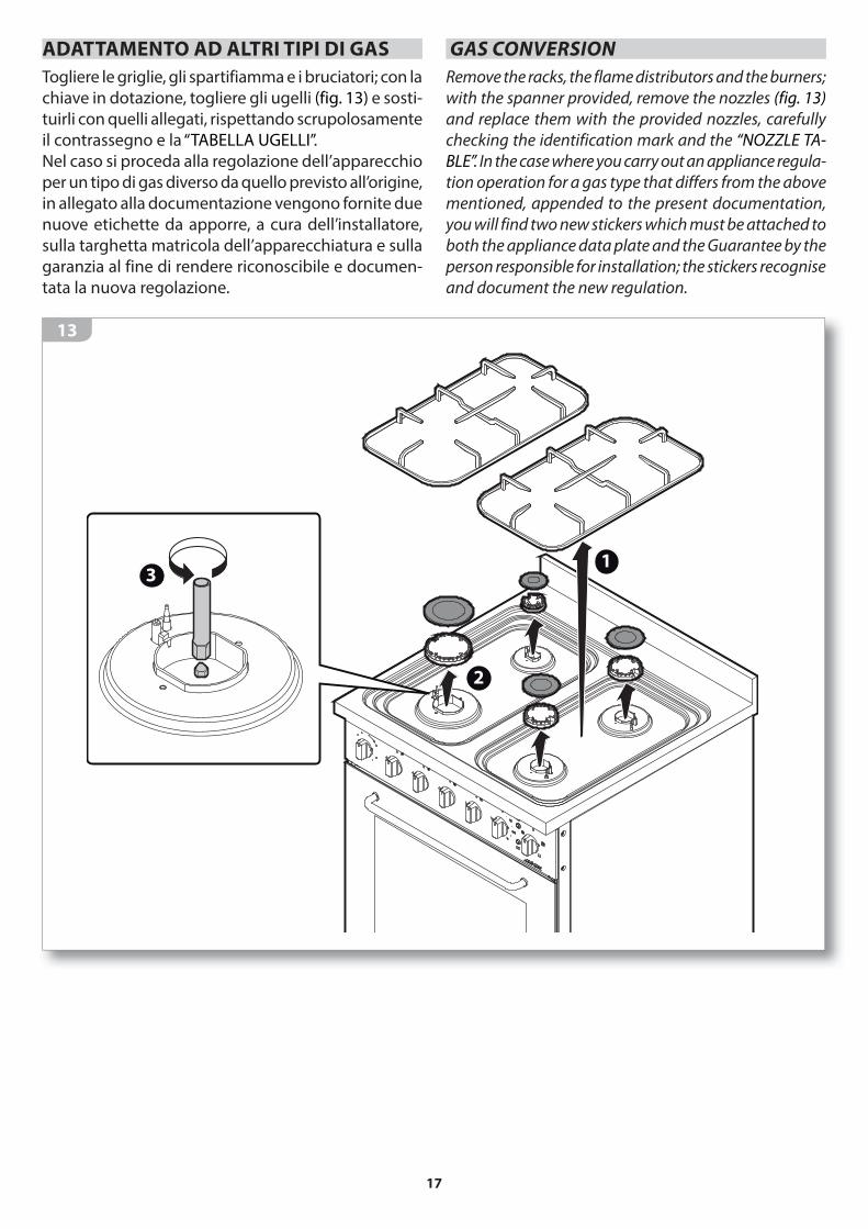
ADATTAMENTO AD ALTRI TIPI DI GAS
Togliere le griglie, gli spartifiamma e i bruciatori; con la
chiave in dotazione, togliere gli ugelli (fig. 13) e sosti-
tuirli con quelli allegati, rispettando scrupolosamente
il contrassegno e la “TABELLA UGELLI”.
Nel caso si proceda alla regolazione dell’apparecchio
per un tipo di gas diverso da quello previsto all’origine,
in allegato alla documentazione vengono fornite due
nuove etichette da apporre, a cura dell’installatore,
sulla targhetta matricola dell’apparecchiatura e sulla
garanzia al fine di rendere riconoscibile e documen-
tata la nuova regolazione.
13
GAS CONVERSION
Remove the racks, the flame distributors and the burners;
with the spanner provided, remove the nozzles (fig. 13)
and replace them with the provided nozzles, carefully
checking the identification mark and the “NOZZLE TA-
BLE”. In the case where you carry out an appliance regula-
tion operation for a gas type that differs from the above
mentioned, appended to the present documentation,
you will find two new stickers which must be attached to
both the appliance data plate and the Guarantee by the
person responsible for installation; the stickers recognise
and document the new regulation.
1
2
3

18
USO USAGE
AVVERTENZE DI SICUREZZA
PER UN USO CORRETTO E SICURO
Questa apparecchiatura è stata concepita e re-
alizzata esclusivamente per la cottura degli ali-
menti. Un uso diverso è considerato improprio
e quindi potenzialmente pericoloso per persone, anima-
li e cose. Inoltre potrebbe danneggiare irrimediabilmen-
te l’apparecchiatura: in questo caso il Costruttore non si
ritiene responsabile e non riconosce il diritto di Garanzia.
Chiudere sempre l’interruttore elettrico on-
nipolare prima di ogni operazione di pulizia
o in previsione di lunga inattività.
Assicurarsi che tutte le manopole siano a
“zero” (“OFF” - chiuso) al termine dell’utilizzo.
Se si dovesse notare una qualsiasi anomalia
non utilizzare l’apparecchiatura e contattare
un Centro di Assistenza autorizzato comuni-
cando i dati presenti nella targa matricola.
Questa apparecchiatura non è adatta all’uso da
parte di persone (inclusi i bambini) con difficoltà
fisiche, sensoriali o mentali o con mancanza di
esperienza e conoscenza, a meno che una persona respon-
sabile della loro sicurezza fornisca a queste una supervi-
sione o un’istruzione riguardo l’uso dell’apparecchiatura.
I bambini devono essere sorvegliati per assi-
curarsi che non giochino con l’apparecchia-
tura o con parti di essa.
Onde evitare pericolosi surriscaldamenti
dovuti ad un uso scorretto dell’apparecchia-
tura oppure ad un difetto dei componenti, il
forno è dotato di un termostato di sicurezza che, in
caso di funzionamento anomalo, stacca l’alimentazio-
ne elettrica. Il ripristino del termostato, in funzione
dell’abbassamento della temperatura del forno, è
automatico. Pertanto in caso di intervento del termo-
stato, per riutilizzarlo è sufficiente attendere il raffred-
damento del forno. In caso contrario, se l’intervento
è determinato da un difetto dei componenti, è neces-
sario far intervenire l’Assistenza tecnica.
SAFETY WARNINGS
FOR SAFE AND CORRECT USE
This appliance has been designed and manufac-
tured exclusively for cooking food. Any other use
is considered improper and thus potentially
hazardous for people, animals and property. Furthermore,
it may permanently damage the appliance: in this case,
the Manufacturer will not be held liable and the War-
ranty will be void.
Always disconnect the appliance from the
power supply using the omnipolar switch before
carrying out any cleaning operations or when
the appliance will not be used for an extended period.
Make sure that the knobs are turned to “zero”
(“OFF”) when you finish to use the oven.
If you should note any anomalies, do not use
the appliance but contact an authorized Service
Centre and report the data indicated on the
data plate.
This appliance is not suited for use by persons
(including children) with physical, sensorial or
mental difficulties or lacking proper experience
and knowledge, unless supervised or instructed on the
use of the appliance by the person responsible for their
safety.
Children must be supervised to ensure that they
do not play with the appliance or parts of it.
To avoid dangerous overheating of the appli-
ance due to incorrect use or a defect in the
components, the oven is provided with a safety
thermostat that disconnects the power supply in case of
a malfunction. The thermostat starts working again
automatically when the temperature of the oven drops.
Therefore, if the thermostat is activated, it can be reused
after waiting for the oven to cool. Otherwise, if the acti-
vation occurred due to a component defect, contact our
technical service.
19
Non appoggiare pesi sulla porta aperta del forno
e non utilizzare la cavità di cottura per conser-
vare cibi umidi o oggetti di qualsiasi natura.
L’area nelle vicinanze della cavità del forno
potrebbe essere molto calda, prestare caute-
la nel posizionare in questo spazio prese di
corrente, altri elettrodomestici, cavi elettrici, tubazioni e
qualsiasi materiale sensibile al calore o infiammabile.
Non utilizzare prodotti spray nelle vicinaze di
questa apparecchiatura mentre è in funzione.
Non modificare questa apparecchiatura.
Pericolo di incendio!
Non utilizzare l’apparecchiatura come piano
di appoggio.
Pericolo di incendio!
Non posizionate mai oggetti sensibili al calore
o infiammabili (es. presine, tende, bottiglie di
alcoolici, ecc..) nelle vicinanze dell’apparecchiatura.
Se il piano cottura è corredato di coperchio è indispensabile verificare sempre che le mano-pole siano in posizione di chiuso e che i bru-
ciatori o le piastre si siano completamente raffreddati
prima di abbassare il coperchio.
Do not rest heavy objects on the oven’s open
door and do not use the cooking cavity to store
moist food or any other type of object.
The area near the oven cavity may become very
hot, so take precautions when positioning
power outlets, other household appliances,
electrical cables, hoses and any heat-sensitive or flam-
mable material in this area.
Do not spray aerosols in the vicinity of this ap-
pliance while it is in operation.
Do not modify this appliance.
Fire hazard!
Do not use the appliance as a support surface.
Fire hazard!
Never place heat-sensitive and flammable
objects (for example, oven gloves, curtains,
alcoholic containers, etc..) near the appliance.
In the instance where the hob features a cover, you must always check that the knobs are in the off position and that the burners or hot plates
are fully cooled down before lowering the cover.

20
PER LA COTTURA
Pericolo di scottature!
Durante il funzionamento e per alcuni minuti
dopo l’utilizzo, l’interno del forno ed alcune
parti esterne raggiungono temperature molto ele-
vate! Non entrare in contatto con queste parti senza
protezioni personali adeguate.
Prima dell’utilizzo verificare che gli spartifiam-
ma, i bruciatori e la griglia siano correttamente
posizionati.
In particolare controllare che la griglia appoggi corretta-
mente sull’apparecchiatura senza traballare.
Pericolo di scottature!
Non toccare gli elementi riscaldanti all’interno
del forno!
Pericolo di scottature!
Essendo accessibili elementi caldi quando in uso, per
evitare ustioni e scottature, i bambini devono essere
tenuti lontani.
Pericolo di incendio!
Non immettere nella cavità di cottura liquidi e/o
ingredienti alcolici durante il funzionamento.
Pericolo di incendio!
Non cucinate mai cibi alla fiamma.
Pericolo di incendio!
Nel caso di incendio del grasso o dell’olio
caldo non spegnere mai le fiamme con acqua
ma soffocarle con un canovaccio umido o similari e
avvisare tempestivamente i vigili del fuoco.
Sorvegliare l’apparecchiatura durante tutto il
suo funzionamento.
Per la cottura utilizzare soltanto recipienti, te-
glie e accessori espressamente concepiti per
tale utilizzo, realizzati in materiali resistenti alle
alte temperature e idonei al contatto con gli alimenti.
Lo sgocciolamento di alcune sostanze nella
cavità del forno (es. acidi della frutta) provocano
macchie che non è possibile rimuovere ma che
non pregiudicano le prestazioni dell’apparecchiatura.
Non versare liquidi freddi sulle pareti della cavi-
tà quando il forno è in funzione: lo sbalzo termi-
co potrebbe creare danni alle pareti interne.
FOR COOKING
Burn hazard!
During operation and for a few minutes after
use, the interior of the oven and some outer
parts reach very high temperatures! Do not touch these
parts without suitable personal protections.
Before using the appliance, check that the flame
distributors, the burners and the rack are cor-
rectly positioned. Check, in particular that the rack
rests correctly on the appliance without slipping or sliding.
Burn hazard!
Care should be taken to avoid touching heating
elements inside the oven.
Burn hazard!
Accessible parts will become hot when in use.
To avoid burns and scalds, children should be
kept away.
Fire hazard!
Do not introduce liquids and/or alcoholic ingre-
dients into the cooking cavity during operation.
Fire hazard!
Never cook food using naked flames.
Fire hazard!
In the case where fats or oils lead to fire, never
put out flames with water, instead suffocate the
flames using a moist dishcloth or a similar material and
immediately call the fire services.
Monitor the appliance during the entire time it
is in operation.
For the cooking, use only containers, pans and
accessories that have been specifically designed
for this use, made of high-temperature-resistant
materials and suitable for contact with foods.
The dripping of some substances in the oven
cavity (e.g., fruit acids) may cause stains which
cannot be removed, but the stains do not com-
promise the appliance’s performance.
Do not splash or pour cold liquids on the walls
of the cavity when the oven is operating: the
thermal stress may damage the interior walls.
21
Accertarsi che i recipienti di cottura appog-
gino correttamente sulla griglia senza trabal-
lare. I recipienti devono avere un diametro
adeguato al bruciatore scelto e non devono sporgere
dalla griglia. il Costruttore non si ritiene responsabile e
non riconosce il diritto di Garanzia se questa norma non
viene applicata.
Un utilizzo intensivo e prolungato dell’appa-
recchiatura può necessitare di una aerazione
supplementare per esempio l’apertura di una
finestra o di una aerazione più efficace aumentando
la potenza di aspirazione meccanica se essa esiste.
Pericolo di esplosione!
Non scaldate mai sull’apparecchiatura scatole
di latta o contenitori chiusi ermeticamente, la
sovrapressione generata dal calore potrebbero farli
esplodere arrecando gravi danni personali.
Pericolo di incendio!Non rivestire l’apparecchiatura o parti di essa con fogli di alluminio o similari.
Nel caso di una estinzione accidentale delle fiamme del bruciatore, portare la manopola in posizione “ - spento” e non ritentare
l’accensione prima di un minuto.
Ensure that the food containers sit correctly on the
rack without slipping or sliding. The food contain-
ers must be correctly proportioned in relation to
the chosen burner and must not protrude the edges of the
rack. The manufacturer will not be held liable and the
Guarantee will be void if this standard is not applied.
In the case where the appliance is going to be
used for an intensive or extensive period of time,
additional ventilation may be required; for ex-
ample, it is advisable to open a window or use a more
efficient ventilation system by upgrading the mechanical
ventilation system (if present).
Explosion hazard!
Never heat up tin cans or hermetically closed
containers on the appliance; the excess pressure
generated by the heat may cause containers to explode,
consequently leading to serious personal injury.
Fire hazard!Do not cover the appliance or parts of the ap-pliance with aluminium foil or similar material.
In the case where the burner flame should ac-cidentally go out, bring the knob to the “ - off” position and do not attempt to re-ignite the
appliance for at least one minute.

22
BEFORE STARTING
UNDERSTANDING THE APPLIANCE
OVEN1 control panel (for details: fig. 24 on page 31)2 oven door3 handle4 upper heating element5 grill heating element6 lower heating element7 rear fan8 lamp9 feet with heights of 15/17 or 9/16 height adjustable
(optional)10 cooking level racks11 data plate12 cavity (oven interior)
13 optional accessories (see “Accessories”) 14 rack: to support the containers (oven dishes, moulds,
etc.) and foods to be grilled;15 drip tray: for cooking roasts or supporting biscuits,
bread products and the like.
PRIMA DI COMINCIARE
CONOSCERE L’APPARECCHIATURA
FORNO
1 frontale comandi (per dettagli: fig. 24 a pag. 31)2 porta del forno3 maniglia4 resistenza superiore5 resistenza grill6 resistenza inferiore7 ventola posteriore8 lampadina9 piedini h. 15/17 o h. 9/16 regolabili in altezza
(optional)10 griglie per livelli di cottura11 targhetta matricola12 cavità (interno forno)
13 accessori opzionali (vedi “Accessori”)
14 griglia: per l’appoggio di contenitori (pirofile,
stampi, ecc...) e pietanze da grigliare;
15 leccarda: per la cottura di arrosti o l’ appoggio di
biscotti, prodotti di panificazione o similari.
14
Optional
Optional
4
6 7
5 8
10
9090
1
1012
13
14
159
2
3
Mod.Art.N°
...V ...Hz ...Kw
Questo apparecchio deve essere installato conformemente
alle norme in vigore. Consultare il libretto istruzioni prima
di installare e usare l’apparecchio
F.lli Barazza S.r.l MADE IN ITALY
11
23
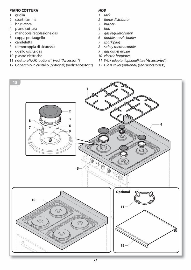
HOB1 rack2 flame distributor3 burner4 hob5 gas regulator knob6 double nozzle holder7 spark plug8 safety thermocouple9 gas outlet nozzle10 electric hotplates
11 WOK adaptor (optional) (see “Accessories”)
12 Glass cover (optional) (see “Accessories”)
PIANO COTTURA
1 griglia2 spartifiamma3 bruciatore4 piano cottura5 manopola regolazione gas6 coppa portaugello7 candeletta8 termocoppia di sicurezza9 ugello uscita gas10 piastre elettriche
11 riduttore WOK (optional) (vedi “Accessori”)
12 Coperchio in cristallo (optional) (vedi “Accessori”)
15
1
5
4
10
2
3
6
97
8
Optional
11
12

24
É BENE SAPERE CHE
Il presente libretto fornisce indicazioni sul funzionamento e la manutenzione di diversi modelli di apparecchiatura; seguire quelle
specifiche per il modello in Vostro possesso. Esso è facilmente riconoscibile in base all’estetica del frontale comandi (fig.19) oppure è rilevabile dalla targhetta matricola (per il suo posizionamento vedere fig.14).
La prima accensione del forno deve avvenire con la cavità di cottura vuota, alla massima temperatura per circa 60 minuti.
Durante questo tempo il forno potrebbe emettere fumo e odori sgradevoli: questo è dovuto alla combu-stione dei grassi utilizzati per la lavorazione in fabbrica dello stesso, arieggiare i locali.Lasciare raffreddare completamente la cavità a porta chiusa e pulire accuratamente il frontale, gli accessori e l’interno della cavità con le modalità indicate nel capitolo dedicato.
In alcuni modelli, un ventilatore tangenziale di raffreddamento si avvia automaticamente du-rante la cottura: esso ha la funzione di raffred-
dare le superfici del forno e di eliminare la normale formazione di vapore all’interno della cavità. Dopo lo spegnimento dell’apparecchiatura il ventilatore rimane in funzione finchè il forno si raffredda evitando cosi il surriscaldamento del mobile.
La luce della cavità forno si accende all’avvio della cottura e rimane accesa, senza possibi-lità di spegnerla manualmente, fino al termine
della cottura.
USEFUL INFORMATION
This booklet provides information about the operation and maintenance of various models; follow the ones specific to your appliance.
It can be easily recognised based on the appearance of the control panel (fig.19) or can be seen on the data plate (for its position fig.14).
When lit for the first time, the oven cooking cav-ity must be empty, and it should be set at maxi-mum temperature for about 60 minutes.
During this time the oven may emit smoke or unpleas-ant odours (due to the burning of the grease used in the factory processing of the oven), so the room should be aired well during its operation.Allow the oven cavity to cool completely with the door closed and thoroughly clean the front panel, accessories and interior of the cavity following the procedures indi-cated in the respective chapter.
With some models a tangential cooling fan starts automatically during cooking in order to cool the oven surfaces and eliminate the normal formation
of steam inside the cavity. After the appliance has been switched off the fan remains in operation until the oven cools, thus preventing the cabinet from overheating.
The light in the oven cavity illuminates when cooking initiates and remains on, without the option of switching it off manually, until cooking
has terminated.

25
QUALCHE CONSIGLIO DI COTTURA• Disporre all’interno dei recipienti o della leccarda i
cibi da cuocere in modo uniforme e ben distribuito
senza eccedere nelle quantità. In caso di utilizzo di
più griglie/leccarde tenerle ben distanziate l’una
dall’altra per permettere una buona circolazione
dell’aria (fig. 16) : in questo caso utilizzare la tipo-
logia di cottura “Multilivello” e prevedere un tempo
di cottura superiore (circa 15 minuti in più).
• Durante la cottura aprire il meno possibile la porta
del forno.
• Si consiglia di infornare con il forno in temperatura.
• Scegliere con attenzione la durata di cottura, la
temperatura e il livello (fig. 17) sul quale posizionare
la griglia o la leccarda.
Anche la scelta del tipo di cottura influisce molto
sul risultato finale.
Esempio: se a fine cottura, si desidera cuocere mag-
giormente la parte superiore della pietanza, posizio-
nare il selettore sul simbolo , per la parte inferiore
sul simbolo della cottura .
Per avere qualche indicazione consultare le tabel-
le “Tabella consigli per cotture” e “Tabella simbo-
logie per tipo di cottura”.
OK!
16
• Impostare sempre la temperatura al valore più basso e,
in caso di bisogno, aumentarlo durante la cottura.
• Il peso degli alimenti da arrostire deve essere ugua-
le o superiore a 1 kg.
• Nel caso di carne molto magra, disporla all’interno
di teglie coperte per mantenere maggior morbidez-
za. Si consiglia inoltre di aggiungere un po’ d’acqua
nella teglia di cottura.
• A metà cottura girare l’arrosto e ricoprirlo di tanto
in tanto con il sugo di cottura.
Per un maggior rendimento durante la fun-
zione grill, si consiglia di impostare una
temperatura inferiore ai 200°C.
SOME COOKING SUGGESTIONS
• Arrange the food to be cooked in the containers or
on drip tray in a well-distributed uniform manner
without overloading. If several racks/drip trays are
being used, space them well in order to ensure good
air circulation (fig. 16) : in this case use the “Multilevel”
cooking mode and increase the cooking time (by
about 15 minutes).
• Open the oven door as little as possible when coo-
king.
• It is recommended that you place the food in the oven
once it has reached the cooking temperature.
• Carefully select the cooking time, temperature and
the level (fig.17) on which you position the rack or
drip tray.
Also the type of cooking selected has a great influence
on the final result.
For example: If at the end of the cooking time you
want to cook the upper part of the dish more, turn
the knob to , for the lower part to ..
For additional suggestions, see the table “Cooking
suggestions table” and “Cooking type symbols
table”.
17
• Always set the temperature at the lowest value and
increase it during the cooking, if necessary.
• The weight of the food to be roasted must be at least
1 kg.
• If the meat is very lean, arrange it in a covered oven
dish in order to keep it as tender as possible. It is also
recommended that you add a bit of water to the
cooking pan.
• Halfway through the cooking, turn the roast over and
coat it with the gravy every now and then.
For a good result using grill function, it is recom-
mended to set the temperature at a value lower
than 200°C.
1
2
3
4
5
6
9090
1
2
3
4
6060
26
18
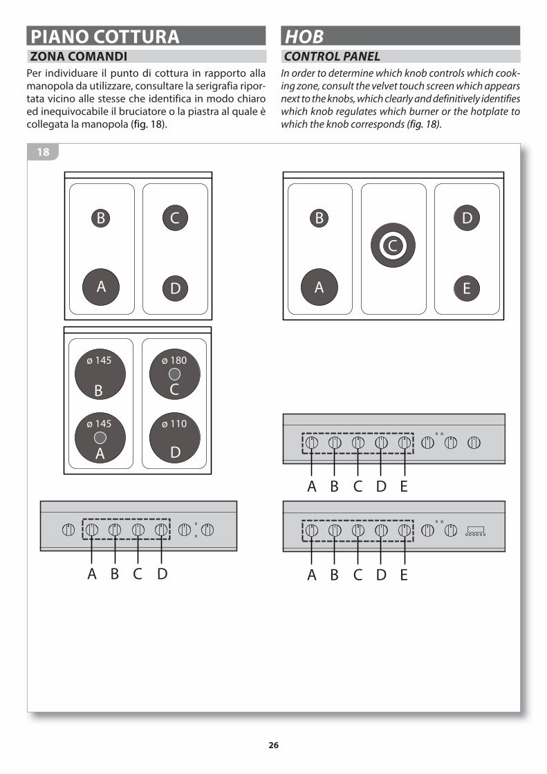
PIANO COTTURA HOB ZONA COMANDI
CONTROL PANEL
Per individuare il punto di cottura in rapporto alla manopola da utilizzare, consultare la serigrafia ripor-tata vicino alle stesse che identifica in modo chiaro ed inequivocabile il bruciatore o la piastra al quale è collegata la manopola (fig. 18).
In order to determine which knob controls which cook-ing zone, consult the velvet touch screen which appears next to the knobs, which clearly and definitively identifies which knob regulates which burner or the hotplate to which the knob corresponds (fig. 18).
A D
CB
A E
C
DB
BA C D E
BA C D EA
ø 145
ø 145
ø 180
ø 110
B C D
A D
B C

27
PIANO A GAS - USO DEI BRUCIATORI
Prima dell’utilizzo verificare che gli spar-
tifiamma (2), i bruciatori (3) e le griglie (1) siano
correttamente posizionati.I bruciatori sono dotati di termocoppia di sicurezza (8). La termocoppia è un dispositivo sensibile al calore: finchè è riscaldata dalla
fiamma del bruciatore acceso permette la fuoriuscita del gas dall’ugello (9); se la fiamma si spegne per qual-siasi motivo (es. una fuoriuscita accidentale di liquido dalla pentola), la termocoppia in pochi secondi si raf-fredda e questo blocca la fuoriuscita del gas dall’ugello impedendo che la stanza si saturi di gas incombusto.
Accensione dei bruciatori1) (fig.19) Premere a fondo la manopola corrispon-
dente al bruciatore che si desidera accendere e contemporaneamente ruotarla fino al simbolo
-> la candela (7) scoccherà le scintille per accen-dere il bruciatore scelto.
2) Ad accensione avvenuta tenere ancora premuta a fondo la manopola per circa 5 secondi mantenen-dola sempre sul simbolo poi rilasciarla: questo tempo serve al riscaldamento della termocoppia di sicurezza. Se al rilascio della manopola il bruciatore non rimanesse acceso, significa che la termocoppia non era ancora sufficientemente calda: ripetere le operazioni 1) e 2) tenendo premuta più a lungo la manopola dopo l’accensione del bruciatore.
Se l’accensione non avviene entro 15 secondi,
riportare il rubinetto nella posizione di chiuso e
attendere almeno 1 minuto prima di eseguire un
nuovo tentativo di accensione.
19
GAS HOB - USING THE BURNERS
Before using the appliance, check that the
flame distributors (2), the burners (3) and the racks
(1) are correctly positioned.The burners are equipped with safety thermo-couples (8). The thermocouple is a heat-sensitive device: it is heated by the ignited burner flame,
which permits the thermocouple to control the gas flow from the nozzle (9); in the case where the flame should go out for whatever reason, (for example, accidental liquid spillage from a saucepan), the thermocouple immediately cools down, blocking the gas flow from the nozzle, subse-quently preventing unburned gas from filling the room.
Switching on the burners1) (fig.19) Press down fully on the knob regulating the
burner you wish to switch on whilst at the same time rotating it until the symbol -> appears; the spark plug (7) will fire sparks in order to switch on the chosen burner.
2) Once ignited, keep pressing down fully on the knob for approximately 5 seconds, still with the symbol
showing, then release the knob: this time period allows the safety thermocouple to heat up. If upon re-leasing the knob, the burner does not remain ignited, this is an indicator that the thermocouple was not sufficiently heated: repeat stages 1) and 2) keeping the knob pressed down for longer after the ignition
of the burner.
Should it not switch on within 15 seconds,
bring the tap to the off position and wait at least 1
minute before trying to switch it on again.
12
3
6
97
8
3 5”
1
2
o

28
Regolazione fiamma3) Controllare che la fiamma sia regolare e stabile, suc-
cessivamente ruotare la manopola nella posizione desiderata (MIN o MAX ).
É possibile posizionare la manopola in posizione intermedia tra la posizione di massimo e quella di minimo, ma NON tra la posizione di massimo e quella di “ - spento” (fig. 20).
Se la fiamma risulta irregolare verificare il corretto posizionamento degli spartifiamma e dei bruciatori.
Cottura4) Posizionate i tegami per la cottura sul bruciatore
acceso: non lasciare gli elementi riscaldanti accesi
senza recipienti o con recipienti vuoti. Per la cottura
utilizzare soltanto pentole, teglie e accessori espressa-
mente concepiti per tale utilizzo, realizzati in materiali
resistenti alle alte temperature e idonei al contatto con
gli alimenti. Per un migliore utilizzo dei bruciatori, è necessario usare recipienti del diametro adatto al tipo di bruciatore scelto, in modo da ottenere il massimo
rendimento con il minimo consumo di gas.
Bruciatore ø Recipiente
Ausiliario
Semirapido
Rapido
Tripla corona
da ø 6 a ø 18
da ø 15 a ø 22
da ø 20 a ø 26
da ø 24 a ø 32
Per un maggiore risparmio energetico è consiglia-
bile cuocere con le pentole chiuse dal coperchio
e ridurre la fiamma quanto basta per mantenere
l’ebollizione non appena un liquido inizia a bollire.
Accertarsi che i recipienti di cottura appoggino correttamente sulla griglia senza traballare. Le pentole devono essere centrate rispetto al bruciatore e NON devono sporgere dalla griglia (fig. 21). Non è consentito utilizzare l’apparecchiatura senza la griglia o con diffusori di calore o riduttori diversi da quelli acquistabili dal Rivenditore (fig. 33).
OK!
20
Flame control3) Check that the flame is steady and stable, subse-
quently rotate the knob to the desired position (MIN or MAX ).
It is possible to set the knob between the maxi-mum and minimum settings, but NOT between the maximum setting and the “ - off” position (fig. 20).
If the flame is irregular, check that the flame distributors and the burners are correctly posi-tioned.
Cooking
4) Place the pan on the lit burner: do not leave burners on
without containers or with empty containers. For cook-
ing, use only containers, pans and accessories that have
been specifically designed for this use, made of high-
temperature-resistant materials and suitable for contact
with foods. For enhanced burner performance, you must use containers with diameters proportioned to the burner type chosen, so that you get maximum performance
using the minimum amount of gas.
Burner ø Container
Auxiliary
Semi- rapid
Rapid
Triple ring
from ø 6 to ø 18
from ø 15 to ø 22
from ø 20 to ø 26
from ø 24 to ø 32
For maximum energy saving, we recommend cooking
with the lids on pans/pots and reducing the flame so that it is simply sufficient enough to maintain boiling
point once a liquid begins to boil.
Ensure that the food containers sit correctly on the rack without slipping or sliding. Pans/pots should be centred on the burner and must NOT protrude the edges of the rack (fig. 21). We do not recommend using the appliance without the rack or with heat diffusers or adapters different to those supplied by the Retailer (fig. 33).
OK!
21

29
Sorvegliare l’apparecchiatura durante tutto il suo funzionamento.
Durante il funzionamento dell’apparecchia-tura saranno rilasciati nell’ambiente umidità, calore e prodotti di combustione. Risulta
quindi fondamentale che il locale sia aerato tramite:
1) aperture naturali (es. finestre, ecc...);
2) aperture artificiali obbligatorie per legge (per le loro
specifiche consultare “Caratteristiche del locale di
installazione”);
3) cappe di aspirazione/elettroventilatori con condot-
to di scarico e potenza adeguata all’intensità d’uso
dell’apparecchiatura.
Periodicamente verificate che le aperture non siano
state accidentalmente ostruite e il perfetto funziona-
mento dei sistemi di aspirazione.
Pericolo di scottature!
Durante il funzionamento e per alcuni minuti dopo
l’utilizzo, alcune parti dell’apparecchiatura rag-
giungono temperature molto elevate! Non entrare in con-
tatto con queste parti senza protezioni personali adeguate.
Spegnimento dei bruciatori5) A cottura ultimata, spegnere l’apparecchiatura
riportando su “ - spento” tutte le manopole.
6) Togliere le pentole dall’apparecchiatura muniti di adeguate protezioni personali di sicurezza.
PIANO A GAS - FUNZIONAMENTO ANOMALO
Le seguenti situazioni sono considerate un funziona-mento anomalo ed è richiesto l’intervento del Servizio Assistenza:- La fiamma del bruciatore è gialla.- Formazione di fuliggine sugli utensili da cucina.- I bruciatori non accendono correttamente.- I bruciatori non rimangono accesi.- I bruciatori si spegnono al movimento delle ante della
cucina.- Le valvole del gas sono difficili da girare.Nel caso in cui l’apparecchio non funzioni correttamen-te, contattare il Servizio Assistenza autorizzato di zona.
Monitor the appliance during the entire time it is in operation.
During operation, humidity, heat and combus-tion emissions will be released into the atmos-phere. Therefore, the area must be well venti-
lated by way of the following:
1) natural ventilation (e.g. windows, etc...);
2) man-made ventilation necessitated by law (for details
see “Installation site characteristics”);
3) extractor hoods/electric fans with outlets and suitably
powered in relation to the usage requirements of the
appliance.
Regularly check that the openings are not accidentally
obstructed and that ventilation systems are functioning
perfectly.
Burn hazard!
During operation and for a few minutes after
use, some parts of the appliance reach ex-
tremely high temperatures! Do not touch these parts
without suitable personal protection.
Switching off the burners5) Once you have finished cooking, switch off the appli-
ance by pressing “ - off” on all the knobs.
6) Remove the pans/pots from the appliance using suit-able personal safety equipment.
GAS HOB - ABNORMAL OPERATION
Any of the following are considered to be abnormal
operation and may require servicing:
- Yellow tipping of the hob burner flame.- Sooting up of cooking utensils.- Burners not igniting properly.- Burners failing to remain alight.- Burners extinguished by cupboard doors.- Gas valves, which are difficult to turn.
In case the appliance fails to operate correctly, contact
the authorised service provider in your area”.

30
PIANO ELETTRICO - USO DELLE PIASTRE
L’accensione delle piastre elettriche avviene ruotando la manopola corrispondente in una delle 4 potenze di cottura disponibili (Fig. 22). La scelta della potenza di cottura dipende dal tipo di cottura che si desidera ottenere; di seguito viene fornita una tabella indicativa.
Spento Riscaldare cibi Cottura normale Cottura intensiva
Arrostire
01-2
(calore minimo)
3
(calore medio)
4(calore massimo)
L’accensione della lampada spia (3) del pannello coman-di segnala quando una piastra è accesa.
Per un miglior funzionamento della piastra elettrica è necessario attenersi a quanto segue (Fig. 23):- Il diametro del fondo della pentola deve essere uguale
o leggermente superiore al diametro della piastra, mai inferiore a quello della piastra stessa.
- Per avere un maggiore risparmio energetico la pentola deve avere il fondo piatto e non convesso ne concavo; La pentola deve essere ben centrata sulla piastra e con il coperchio.
- Evitare di appoggiare la pentola bagnata sulla piastra;- Evitare l’uso della piastra senza pentola.- Appena un liquido inizia a bollire, è consigliabile,
ridurre la potenza quanto basta per mantenere l’e-
bollizione.
L’eventuale presenza del coperchio in cristallo riduce a 22 cm. il Ø massimo del recipiente utilizzabile sulle piastre posteriori.
22
OK!
23
4
3
3
2
1
0
ELECTRIC HOB - USING THE HOTPLATES
To turn on the electric hotplate, you must rotate the cor-responding knob to one of the cooking power options available (Fig. 22). The cooking power selection depends on the desired type of cooking; a table listing guidelines is provided as follows.
Off Heating foodStandard cook-
ing
Fan assisted ovenRoasting
01-2
(minimum heat)
3
(medium heat)
4(maximum heat)
Lighting of the indicator light (3) on the control panel indicates that a hotplate is on.
For enhanced operation of the electric hotplate, you must
comply with the following (Fig. 23):- The diameter of the pan base must be equal to or slightly
larger than the hotplate diameter, however, it must be smaller than the hotplate itself.
- To ensure maximum energy-saving, the base of the pan must be flat and not convex or concave. The pan must carefully be centred on the hotplate and must also have its cover.
- Avoid resting wet pans on the hotplate;- Avoid using the hotplate without a pan.- As soon as a liquid begins to boil, we recommend lower-
ing the power so that it is just enough to keep the liquid boiling.
The presence of a glass cover reduces the maxi-mum Ø of the recipient which can be used on back hotplates, to 22 cm.

31
FORNO OVENS
24
1 manopola termostato: permette di impostare la temperatura desiderata
2 manopola selettore: permette di scegliere il tipo di cottura desiderata
3 spia funzionamento generale: - forni elettrici: indica che l’apparecchiatura è
accesa;
- nei forni a gas: segnala che si sta utilizzando
la funzione “grill”.
4 spia funzionam. collegata al termostato: allo
spegnimento, indica che è stata raggiunta la
temperatura impostata nella cavità del forno5 programmatore digitale: permette di pro-
grammare una cottura6 manopola contaminuti: permette di impostare
un tempo di cottura7 manopole piano cottura: accendono e regola-
no la potenza dei bruciatori/delle piastre del piano cottura
1 thermostat knob: used to set the desired tem-perature
2 selector knob: used to select the desired cooking type
3 main operation indicator light:
- electric ovens: indicates that the appliance is on;
- with gas ovens: indicates that the “grill” function is in operation.
4 operation indicator light connected to the ther-mostat: when it turns off, this indicates that the desired set oven cavity temperature has been reached
5 digital programmer: used to program cooking6 timer knob: used to set the cooking time7 hob knobs: switch on and used to adjust the hob
burner/hotplate power
90 cmCucineCookers
90 cmCucineCookers
70 cmCucineCookers
50/60 cmCucineCookers
34
612
34
12
5
6 1 2
3
4
4 21
3
7
7
7
76
0
50
100
150200
MAX
0
30
45 15
0
4
32
1
0
0
270
240210
180
150
0 0
1 6
2
7
gas / gas StaticoStatic
MultisetteMultiseven
MultiprogramMultifunzioneMultifunction
comando elettricoelectric control
forno elettrico electric oven
forno gasgas oven
comando gasgas control
termostato / thermostat
manopole piano / hob knobs
selettore / selector

32
USING THE OVEN
For information on cooking times and tempera-
tures, consult the table “Cooking type symbols
table”.1) TEMPERATURE: rotate the thermostat knob (1) to set the
temperature inside the oven cavity: a thermostat will keep it constant while cooking.
2) COOKING TYPE: rotate the selector knob (2) to ac-tivate the various heating elements in the oven cavity to obtain different cooking re-sults depending on the dish to be cooked
(see the “Cooking type symbols table”).
With gas ovens, the selector (2) is only used to switch on the oven cavity light and to activate the “grill” function: switching on of the oven burner is simply achieved rotating the knob (1) to the desired temperature.
3) COOKING DURATION
A) OVENS WITH TIMER:: (fig. 25) the timer knob (6)
enables the setting, at any moment, of a time, after which the appliance will emit an acoustic signal (warning! the oven must be manually switched off).
Use: rotate the knob clockwise one complete turn to load the mechanical timer knob ( ), then turn it anticlockwise until reaching the desired time ( ). The knob will automatically rotate round from the set time until it reaches “0” ( ).
USO DEL FORNOPer indicazioni su tempi e temperature di cottura,
consultare la tabella “Tabella simbologie per tipo
di cottura”.
1) TEMPERATURA: ruotare la manopola termostato (1) per impostare la temperatura all’interno della cavità del forno: un termostato provvederà a mantenerla costante durante tutta la cottura.
2) TIPO DI COTTURA: ruotare la manopola selettore (2) per attivare le diverse resistenze della cavità del forno, questo consente di ottenere risultati di cottura diversi a seconda della pietanza da cuocere (con-sultare la “Tabella simbologie per tipo di cottura”).
Nei forni a gas, l’utilizzo del selettore (2) serve unicamente per l’accensione della luce nella cavità forno e per attivare la
funzione “grill”: l’accensione del bruciatore forno avviene semplicemente ruotando la manopola (1) sulla temperatura desiderata.
3) DURATA DI COTTURA:
A) FORNI CON CONTAMINUTI (TIMER): (fig. 25) la ma-nopola contaminuti (6) permette di impostare, in qualsiasi momento, un tempo, al termine del quale l’apparecchiatura emetterà un segnale acustico (attenzione! lo spegnimento del forno deve essere fatto manualmente).
Utilizzo: ruotare la manopola in senso orario di un giro completo per caricare il contaminuti meccanico ( ), successivamente ruotarla in senso antiora-rio fino a portarsi sulla durata desiderata ( ). La manopola ruoterà automaticamente dal tempo impostato fino a portarsi sullo “0” ( ).
1
5
2 3
35 min
mechanicalloading
caricamento meccanico
MANUALE / MANUAL MANUALE / MANUAL
AUTOMATICO / AUTOMATIC
64
Drin!!
0
30
45 15
0
30
45 15
0
30
15
0
30
45 15
0
30
45 15
0
30
45 15
35
25

33
Before starting, you should know that
• An acoustic signal will go off for approx. 8/10 minutes,
signalling that the cooking has ended (in manual mode
only if the programmer is used as a timer).
(fig. 27) If you wish to change the intensity (there are
three tones), press button (5) repeatedly; if instead you
wish to turn it off early, press button (4).
• You can use the “+” or “-” buttons to increase/decrease
one unit at a time touching the symbols quickly and re-
peatedly or, to advance quicker, keep the button pressed
down.
• If the acoustic signal that indicates the end of
cooking is turned off early, the oven will turn on in
manual mode; to turn it off turn knobs (1) and (2)
that set the temperature and cooking type to “0”.
26
Prima di iniziare è bene sapere che
• Un segnale acustico, per circa 8/10 minuti, segnala il
termine della cottura (in modalità manuale solo se si
utilizza il programmatore come contaminuti).
(fig. 27) Se si desidera variarne l’intensità (esistono
tre tonalità), premere ripetutamente il tasto (5);
se invece si desidera interromperlo anzitempo
premere il tasto (4).
A
U
T
O
P
A
U
T
O
P
BEEP BEEP
BEEP
BEEP
27
• Quando si utilizzano i tasti “+” o “-” è possibile au-
mentare/diminuire di una unità alla volta con veloci
e ripetuti tocchi sui simboli oppure, per avanzare più
velocemente, tenere continuamente premuto il tasto.
• Se il segnale acustico che segnala la fine della
cottura viene interrotto anzitempo, il forno si
riaccenderà in modalità manuale; per spegnerlo
portare a “0” le manopole (1) e (2) che impostano
la temperatura e il tipo di cottura.
Description commands
1 - Timer programming
2 - Programming the cooking time
3 - Programming the cooking end time
4 - Manual programming
5 - Regulating button -
6 - Regulating button +
Descrizione comandi
1 - Programmazione contaminuti
2 - Programmazione durata cottura
3 - Programmazione fine cottura
4 - Programmazione manuale
5 - Tasto regolazione -
6 - Tasto regolazione +
B) FORNI CON PROGRAMMATORE DIGITALE: fig. 26 B) OVENS WITH ELECTRONIC PROGRAMMER: fig. 26
1 2 43 5 6
A
U
T
O
P

34
• Se durante il funzionamento del forno dovesse man-
care la corrente, al ripristino, i parametri programmati
NON saranno tenuti in memoria e quindi il program-
matore va nuovamente impostato.
• Un programma si annulla automaticamente una volta
eseguito oppure premendo il tasto (4).
Impostare l’ora
Dopo l’allacciamento alla rete elettrica, in caso di black
out o di cambio dell’ora è necessario impostare l’ora
esatta premendo il tasto (4) e successivamente i tasti
“+” o “-” (fig. 28).
A
U
T
O
P
A
U
O
P
A
U
T
O
P
28
Cominciare a cucinare
Impostare il programmatore scegliendo la modalità di cottura MANUALE, MANUALE CON IMPOSTAZIONE SEMIAUTOMATICA o MANUALE CON IMPOSTAZIONE AUTOMATICA. Attenzione! Per annullare un errore di programma-
zione premere il tasto (4) e ricominciare.
Se si utilizzano le modalità di cottura MANUA-LE o MANUALE CON IMPOSTAZIONE SEMIAU-TOMATICA, è consigliabile infornare le pietan-
ze quando il forno ha raggiunto la temperatura
impostata (la spia termostato (4) deve essere spenta)
scegliendo con attenzione il livello al quale posizio-
narle (vedi fig. 17 a pag. 25).
MANUALE (accensione e spegnimento manuale)
L’accensione e lo spegnimento del forno sono manuali e si ottengono semplicemente agendo sulle manopole
che impostano la temperatura e tipo di cottura.Se si desidera, in questa modalità è inoltre possibile uti-
lizzare il programmatore come semplice contaminuti; al termine del tempo impostato un suono avviserà che la cottura è terminata e l’utente deciderà se proseguirla
o interromperla.
• If there is a power failure while the oven is operating,
when it is restored the programmed parameters will
NOT be kept in the memory, therefore the programmer
must be set again.
• Once done, a programme is cancelled automatically, or
by pressing (4).
Setting the time
After connecting to the mains, in the case of a black out
or a time change the exact time must be set by pressing
(4) and then the “+” or “-” buttons (fig. 28).
A
U
T
O
P
A
O
P
A
U
T
O
P
29
Starting to cook
Set the programmer by selecting a cooking mode: MA-
NUAL, MANUAL WITH SEMIAUTOMATIC SETTINGS or
MANUAL WITH AUTOMATIC SETTINGS
Caution! If you make a mistake, press button (4) and
start again.
If you are using the MANUAL or MANUAL WITH
SEMIAUTOMATIC SETTINGS cooking mode, it is
recommended that you place the food in the
oven once it has reached the set temperature (the
thermostat control light (4) must turn off) choosing the
level on which you position it carefully (see fig. 17 on page
25).
MANUAL (the oven is turned on and off manually)
The oven is turned on and off manually and this is done by turning the knobs that set the temperature and the cooking type.If you want, the programmer can be used in this mode as a simple timer; at the end of the set time, a bell will indicate that the cooking is complete and the user can
decide to continue or stop it.

35
A) Cottura manuale senza contaminuti: Per far funzionare il forno, è sufficiente impostare
tramite le manopole (1) e (2) la temperatura e il tipo
di cottura desiderate senza bisogno di utilizzare il
programmatore.
Il forno partirà immediatamente e resterà acceso fino a che le manopole saranno riportate manual-mente sullo zero.
B) Cottura manuale con contaminuti (fig. 29): Impostare tramite le manopole (1) e (2) la tempe-
ratura e il tipo di cottura desiderate e utilizzare il programmatore come semplice contaminuti: per far ciò, premere il tasto (1) e impostare la durata
desiderata con i tasti “-” e “+”: si accenderà il relativo simbolo.
Dopo alcuni secondi il tempo impostato viene memorizzato, sul display riappare l’orario attuale e il forno si accende immediatamente.
Allo scadere del tempo programmato il simbolo del tasto (1) si spegne ed entra in funzione il segnale acustico che dura circa 8/10 minuti (per interrom-perlo anzitempo è sufficiente premere il tasto (4)).
A questo punto l’utente può decidere se proseguire
la cottura o interromperla portando a “0” entrambe
le manopole.
MANUALE CON IMPOSTAZIONE SEMIAUTOMATICA (accensione manuale e spegnimento automatico) In questa modalità è possibile programmare lo spe-
gnimento automatico in base alla durata di cottura
oppure in base all’orario di fine cottura.
Dopo aver impostato, tramite il programmatore uno
dei due parametri, il forno parte manualmente agendo
sulle manopole che impostano la temperatura e il
tipo di cottura.
Al termine del tempo impostato un suono avviserà
che la cottura è terminata e il forno si spegnerà au-
tomaticamente.
A) Durata di cottura programmata (fig. 30)
Premere il tasto (2) e impostare la durata di cottura
con i tasti “-” e “+”; successivamente ruotare le ma-
nopole (1) e (2) sulla temperatura e il tipo di cottura
desiderate.
Il forno parte immediatamente e sul display si
illuminano e il simbolo “Auto”.
Allo scadere del tempo impostato il forno si spegne
automaticamente, sul display lampeggia il simbolo
“Auto” ed entra in funzione un segnale acustico.
Per interrompere anzitempo il segnale premere il
tasto (4): il forno si riaccende in modalità manuale
(per spegnerlo portare a “0” le manopole (1) e (2)
che impostano la temperatura e tipo di cottura).
A) Manual cooking without a timer:
To operate the oven, use knobs (1) and (2) to set the
desired temperature and cooking type without using
the programmer.
The oven will start immediately and will remain on
until the knobs are turned manually to zero.
B) Manual cooking with a timer (fig. 29):
Use knobs (1) and (2) to set the temperature and
cooking time you want and use the programmer as
a simple timer: to do this, press button (1) and set the
desired time with the “-” and “+” buttons: the relative
symbol will turn on.
After a few seconds, the set time is stored. The current
time will reappear on the display and the oven will turn
on immediately.
At the end of the programmed time, the symbol of
button (1) turns off and the acoustic signal will go off
for approx. 8/10 minutes (to turn it off earlier, simply
press button (4)).
The user can now decide to continue with cooking or
stop it by turning both knobs to “0”.
MANUAL WITH SEMIAUTOMATIC SETTINGS
(the oven is turned on manually and turns off automatically)
In this mode, you can programme the oven to turn off
automatically based on the cooking time or based on
the end of cooking time.
After setting one of the two parameters using the pro-
grammer, the oven is started manually using the knobs
that set the temperature and the cooking type.
At the end of the set time, a bell will indicate that the coo-
king is complete and the oven will turn off automatically.
A) ) Programmed cooking time (fig. 30)
Press button (2) and set the cooking time using the “-”
and “+” buttons; then turn the knobs (1) and (2) to the
desired temperature and cooking type.
The oven will start immediately and and the
symbol “Auto” will light up.
At the end of the set time, the oven will turn off auto-
matically, the symbol “Auto” will flash on the display
and an acoustic signal will go off.
To turn it off earlier press the button (4): the oven will
turn on again in manual mode (to turn if off turn
knobs (1) and (2) that set the temperature and
cooking type to “0”).

36
A
U
T
O
P
A
U
T
O
P
A
U
T
O
P
30
B) Fine cottura programmata (fig. 31)
Premere il tasto (3) e impostare l’orario di fine cot-
tura con i tasti “-” e “+”; successivamente ruotare
le manopole (1) e (2) sulla temperatura e il tipo di
cottura desiderate.
Il forno parte immediatamente e sul display si
illuminano e il simbolo “Auto”.
Al raggiungimento dell’orario impostato il forno si
spegne automaticamente, sul display lampeggia
il simbolo “Auto” ed entra in funzione un segnale
acustico.
Per interrompere anzitempo il segnale premere il ta-
sto (4): il forno si riaccende in modalità manuale
(per spegnerlo portare a “0” le manopole (1) e (2)
che impostano la temperatura e tipo di cottura).
MANUALE CON IMPOSTAZIONE AUTOMATICA
(accensione e spegnimento automatici)
In questa modalità si possono programmare sia la durata di cottura che l’orario di fine cottura: una volta stabiliti questi due parametri il forno NON partirà subito ma successivamente, in modo automatico, in base alla durata di cottura impostata e all’ora in cui si desidera che la pietanza sia pronta. Es. durata di cottura impostata: 1 ora e 30 minuti,
fine cottura impostata: 13:00 (ora in cui si desidera
pronta la pietanza) -> il forno inizierà automatica-mente la cottura alle ore 11:30
Al termine del tempo impostato un suono avviserà che la cottura è terminata e il forno si spegnerà au-
tomaticamente.
1) Premere il tasto (2) e impostare la durata di cottura
con i tasti “-” e “+” -> si illuminano e il simbolo
“Auto” (fig. 17).
2) Premere il tasto (3) e impostare l’orario di fine cot-
tura con i tasti “-” e “+” : l’alimentazione del forno
viene interrotta e si spegne (fig. 32).
3) Ruotare le manopole (1) e (2) sulla temperatura e il
tipo di cottura desiderate.
Il forno non partirà immediatamente ma il program-
matore calcolerà l’ora in cui farlo partire automati-
A
U
T
O
P
A
U
T
O
P
A
U
T
O
P
31
B) Programmed end of cooking time (fig. 31)
Press button (3) and set the end of cooking time using
the “-” and “+” buttons; then turn the knobs (1) and
(2) to the desired temperature and cooking type.
The oven will start immediately and and the
symbol “Auto” will light up.
When the set time is reached, the oven will turn off
automatically, the symbol “Auto” will flash on the
display and an acoustic signal will go off.
To turn it off earlier. press the button (4): the oven will
turn on again in manual mode (to turn if off turn
knobs (1) and (2) that set the temperature and
cooking type to “0”).
MANUAL WITH AUTOMATIC SETTINGS
(the oven is turned on and off automatically)
In this mode, you can programme both the cooking time as well as the end of cooking time: once these two para-meters are set the oven will NOT start immediately but later, in automatic mode, based on the set cooking time and the time you want the dish to be ready. Example: cooking time set: 1 hour and 30 minutes,
cooking end time set: 13:00 (time at which you would like the food to be ready) -> the oven will automatically start cooking at 11:30
At the end of the set time, a bell will indicate that the cooking is complete and the oven will turn off auto-
matically.
1) Press the button (2) and set the cooking time with the
“-” and “+” buttons -> and the “Auto” symbol will
light up (fig. 17).
2) Press the button (3) and set the end of cooking time
with the “-” and “+” buttons: the oven’s power supply
will be shut off and will turn off (fig. 32).
3) Turn the knobs (1) and (2) to the desired temperature
and cooking time.
The oven will not start immediately but the program-
mer will calculate the time it will start automatically,

37
camente tenendo conto della durata e dell’orario
di fine cottura impostato.
Allo scadere del tempo impostato il forno si spegne
automaticamente, sul display lampeggia il simbolo
“Auto” ed entra in funzione un segnale acustico.
Per interrompere anzitempo il segnale premere il
tasto (4): il forno si riaccende in modalità manuale
(per spegnerlo portare a “0” le manopole (1) e (2)
che impostano la temperatura e tipo di cottura).
A
U
T
O
P
A
U
T
O
P
A
U
T
O
P
A
U
T
O
P
A
U
T
O
P
A
U
T
O
P
32
4) USO DEL GIRARROSTO (SE PREVISTO):
considering the cooking time and the end of cooking
time that were set.
At the end of the set time, the oven will turn off automa-
tically, the symbol “Auto” will flash on the display and an
acoustic signal will go off.
To turn it off earlier. press the button (4): the oven will
turn on again in manual mode (to turn if off turn
knobs (1) and (2) that set the temperature and coo-
king type to “0”).
4) USING THE ROTISSERIE (WHERE PRESENT)
32
6
90 cmCucineCookers
50/60/70 cmCucineCookers
50/60/70 cmCucineCookers
4
5
41
2 3
LivelloLevel 2
LivelloLevel 4
90 cmCucineCookers
50/60/70 cmCucineCookers
x2
x1
5
6
7
90 cmCucineCookers
Girrarosto tradizionale (grill)Static rotisserie (grill)
Girrarosto a cottura intensiva (grill + ventola)Fan assisted rotisserie (grill + fan)
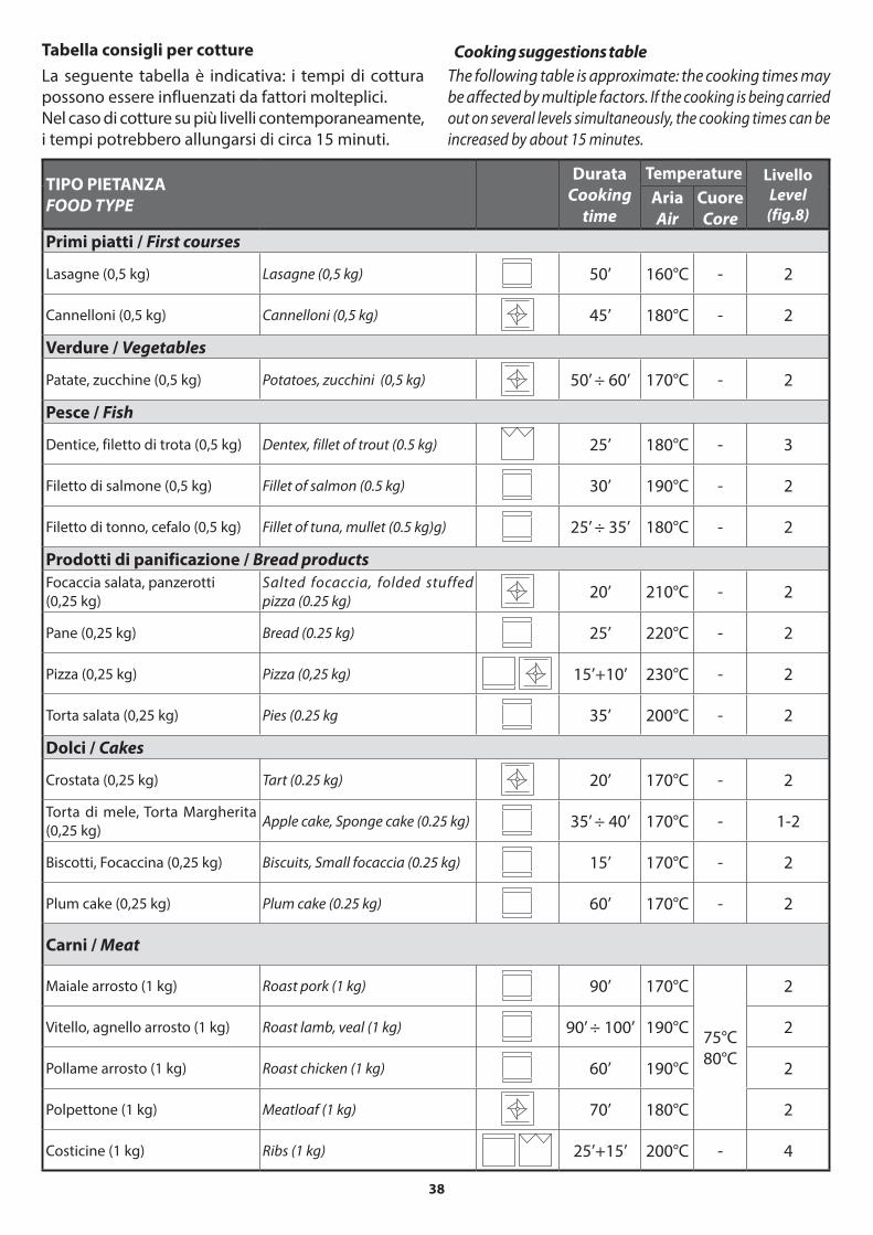
38
Tabella consigli per cotture Cooking suggestions table
TIPO PIETANZAFOOD TYPE
DurataCooking
time
Temperature LivelloLevel
(fig.8)AriaAir
CuoreCore
Primi piatti / First courses
Lasagne (0,5 kg) Lasagne (0,5 kg) 50’ 160°C - 2
Cannelloni (0,5 kg) Cannelloni (0,5 kg) 45’ 180°C - 2
Verdure / Vegetables
Patate, zucchine (0,5 kg) Potatoes, zucchini (0,5 kg) 50’ ÷ 60’ 170°C - 2
Pesce / Fish
Dentice, filetto di trota (0,5 kg) Dentex, fillet of trout (0.5 kg) 25’ 180°C - 3
Filetto di salmone (0,5 kg) Fillet of salmon (0.5 kg) 30’ 190°C - 2
Filetto di tonno, cefalo (0,5 kg) Fillet of tuna, mullet (0.5 kg)g) 25’ ÷ 35’ 180°C - 2
Prodotti di panificazione / Bread products
Focaccia salata, panzerotti
(0,25 kg)
Salted focaccia, folded stuffed
pizza (0.25 kg)20’ 210°C - 2
Pane (0,25 kg) Bread (0.25 kg) 25’ 220°C - 2
Pizza (0,25 kg) Pizza (0,25 kg)
15’+10’ 230°C - 2
Torta salata (0,25 kg) Pies (0.25 kg 35’ 200°C - 2
Dolci / Cakes
Crostata (0,25 kg) Tart (0.25 kg) 20’ 170°C - 2
Torta di mele, Torta Margherita
(0,25 kg)Apple cake, Sponge cake (0.25 kg) 35’ ÷ 40’ 170°C - 1-2
Biscotti, Focaccina (0,25 kg) Biscuits, Small focaccia (0.25 kg) 15’ 170°C - 2
Plum cake (0,25 kg) Plum cake (0.25 kg) 60’ 170°C - 2
Carni / Meat
Maiale arrosto (1 kg) Roast pork (1 kg) 90’ 170°C
75°C
80°C
2
Vitello, agnello arrosto (1 kg) Roast lamb, veal (1 kg) 90’ ÷ 100’ 190°C 2
Pollame arrosto (1 kg) Roast chicken (1 kg) 60’ 190°C 2
Polpettone (1 kg) Meatloaf (1 kg) 70’ 180°C 2
Costicine (1 kg) Ribs (1 kg)
25’+15’ 200°C - 4
La seguente tabella è indicativa: i tempi di cottura
possono essere influenzati da fattori molteplici.
Nel caso di cotture su più livelli contemporaneamente,
i tempi potrebbero allungarsi di circa 15 minuti.
The following table is approximate: the cooking times may
be affected by multiple factors. If the cooking is being carried
out on several levels simultaneously, the cooking times can be
increased by about 15 minutes.

39
Contatti generali e lampada forno Main contacts and oven light
Cottura tradizionaleResistenza superiore + resistenza infe-riore. Cottura di qualsiasi tipo di piatto, ideale per torte lievitate, pizze, arrosti e sformati.
Static ovenUpper heating element + lower heating element. Cooking of any kind of dish; ideal for leavened cakes, pizzas, roasts and flans.
Cottura finale/riscaldareSola resistenza inferiore.Completamento cottura di biscotti, crostate e torte salate e per riscaldare le vivande.
Warming ovenLower heating element only.Finishing off cooking biscuits, tarts and pies and heating drinks.
RosolaturaSola resistenza superiore. Doratura della superficie delle pietanze (es. lasagne, sformati di pasta o verdure).
Browning ovenUpper heating element only. Browning the surfaces of foods (e.g.: lasa-gne, pasta or vegetable flans).
Grill tradizionaleSola resistenza superiore centrale.Cottura di carni di medio/piccolo spes-sore e tostatura del pane.
Traditional grillCentral upper heating element only.Cooking meats with small/medium thick-ness and toasting of bread.
Grill ventilatoSola resistenza superiore centrale + ventola. Cottura di carni di grosso spessore e pietanze particolarmente voluminose.
Fanned grillFan + central upper heating element only. Cooking of thick meat and high-volume foods.
Cottura intensivaResistenza superiore + resistenza infe-riore + ventola. Cotture rapide e uni-formi anche per preparazioni delicate come biscotti e pasticceria.
Fan assisted ovenUpper heating element + lower heating element + fan. Rapid and even cooking for delicate foods such as biscuits and cakes.
Scongelamento rapidoL’utilizzo della sola ventola senza alcun tipo di riscaldamento (termostato a “0”) consente di scongelare i cibi in tempi ridotti ed in modo ottimale.
Defrost functionUsing just the fan, without any type of heat-ing (thermostat at “0”), food is defrosted quickly and optimally.
Girrarosto a cottura intensivaResistenza superiore centrale + ventola. Cottura allo spiedo rapida e intensiva.
Fan assisted rotisserieCentral top heating element+ fan. Rapid and fan-assisted cooking on the rotisserie.
Girrarosto tradizionale (grill)Resistenza superiore centrale.Cottura tradizionale allo spiedo.
Static rotisserie (grill)Central upper heating element.Static oven with rotisserie
Cooking type symbols table /Tabella simbologie per tipo di cottura

40
POSSIBILI CAUSE DI INSUCCESSO TROUBLESHOOTING
Rispetto ai forni posseduti in precedenza i tempi di cottura o le temperature da utiliz-zare per il Vostro nuovo forno potrebbero
essere molto diversi.Si consiglia pertanto, finchè non si acquisisce una
certa esperienza, di attenersi alle indicazioni for-
nite dalla “Tabella simbologie per tipo di cottura”a
pag. 39.
With respect to your previous ovens, the
cooking times and temperatures to be used
for your new oven may be very different.
Therefore, until you gain adequate experience, it
is recommended that you follow the instructions
provided in the “Cooking type symbols table” on
page 39
Risultato: Possibile causa
Pietanze poco dorate/
cotte in superficie o
bruciate nella parte
inferiore
Altezza di inserimento non
corretta
Tipologia di cottura errata
(es. utilizzo della sola
resistenza inferiore)
Torte poco lievitate,
eccessivamente
umide
Temperatura del forno
troppo bassa
Tempo di cottura troppo
breve
Impasto troppo liquido
Troppe aperture della
porta durante la cottura
P i e t a n z e t r o p p o
asciutte e secche
Temperatura del forno
troppo alta
Tempo di cottura troppo
lungo
Contenitore utilizzato non
adatto alla pietanza o alla
tipologia di cottura scelta
Pietanze non cotte
uniformemente
Disposizione errata delle
pietanze nei contenitori
Altezza di inserimento non
corretta
Tipologia di cottura errata
(es. utilizzo della sola
resistenza inferiore)
Result: Possible cause
Food not browned/
cooked enough on the
surface or burned on
the lower part
Incorrect insertion height
Incorrect cooking type
(e.g.: use of the lower heating
element only)
Cakes not leavened
enough too moist
Oven temperature too low
Cooking time too short
Dough too runny
Oven door opened too
often during cooking
Food too dry
Oven temperature too high
Cooking time too long
Container used is unsuit-
able for the food or the
selected cooking type
Food not cooked evenly
Incorrect arrangement of
the food in the containers
Incorrect insertion height
Incorrect cooking type
(e.g.: use of the lower heat-
ing element only)

41
33
ACCESSORIES ACCESSORI
GRIGLIE ESTRAIBILILa manipolazione e l’estrazione delle pietanze e degli strumenti di cottura sono facilitate da guide estraibili (fig. 33) rese sicure da un dispositivo di bloccaggio a fine corsa.
PANNELLI AUTOPULENTIIl forno può essere dotato di pannelli autopulenti (fig. 18), le cui superfici, trattate per sfruttare l’azione del calore, innescano automaticamente un processo di pulizia: i grassi vengono polverizzati e possono esse-re facilmente eliminati con un panno umido, senza ricorrere a detersivi. Per la loro rimozione è sufficiente sfilarli dai 4 perni superiori ed inferiori dopo aver rimosso le griglie laterali per i livelli di cottura (fig. 35).
PIASTRA PER PIZZALa piastra per pizza (fig. 33) è in materiale refrattario, ideale per pizza, focacce e pietanze surgelate.Come utilizzarla:1) A forno freddo, collocare la griglia sul livello 1 (vedi
fig. 8) e su di essa appoggiare la piastra per pizza cosparsa di poca farina o semolino di grano duro.
2) Riscaldare il forno selezionando (viene attivata la ventilazione abbinata alla resistenza cielo e alla resistenza suola).
3) Dopo circa 45 minuti spegnere il forno poichè la piastra per pizza ha raggiunto la temperatura giusta.
4) Posizionare la pizza sopra la piastra calda facendo at-tenzione a non scottarsi. Il tempo di cottura è indicati-vamente di circa 5 - 7 minuti: la pizza è comunque pronta quando la crosta attorno a essa sarà rialzata e croccante.
Note: se le pizze da cuocere sono due, al punto 3) non spegnere il forno ma lasciare accesa soltanto la resistenza suola selezionando .Per la pulizia utilizzare delle spazzole. Non lavare in lavastoviglie.
RIDUTTORI Adattatore in ghisa per pentola WOK.
COPERCHIO IN CRISTALLOCoperchio in cristallo, bianco o nero, disponibile per versioni da 60 o 90.
TELESCOPIC OVEN RAILS
The handling and extraction of the dishes and cooking tools is made easier by the removable racks (fig. 33) which are secured by a stop locking device.
SELF-CLEANING PANELS
The oven can be equipped with self-cleaning panels (fig. 18), the surfaces of which have been treated to use the action of the heat to automatically trigger a cleaning process: the grease is pulverized and can be removed eas-ily with a damp cloth, without having to use detergent. To remove the panels, just slip them off the 4 upper and lower pins after having removed the side racks for the cooking levels (fig. 35) .
PIZZA PLATE
The pizza plate (fig. 33) is made of refractory material and is ideal for pizza, focaccia and frozen foods.How to use it:1) When the oven is cool, place the rack on level 1 (see
fig. 8) and rest the pizza plate, dusted lightly with flour or durum-wheat semolina, on the rack.
2) Heat the oven by selecting (which activates the fan combined with the upper heating element and lower heating element ).
3) After about 45 minutes, switch off the oven since the pizza pan has reached the right temperature.
4) Position the pizza on the hot pizza plate, being careful not to burn yourself. The cooking time is approxi-mately 5 - 7 minutes: the pizza is ready when the crust around it is raised and crispy.
Note: if you are cooking two pizzas, at point 3) do not switch off the oven but leave only the lower heating element on by selecting .The pizza pan can be cleaned using brushes. Do not wash it in the dishwasher.
ADAPTERS
Cast iron WOK adapter.
GLASS COVER
Glass white or black cover available for 60 cm or 90 cm versions

42
AVVERTENZE DI SICUREZZA
Spegnere sempre l’interruttore elettrico principale, staccare la spina di collegamen-to e chiudere i rubinetti di alimentazione
gas prima di ogni operazione di pulizia o in previ-sione di lunga inattività.
Periodicamente controllare che il tubo di
alimentazione gas e il cavo elettrico siano
integri e non schiacciati: nel caso si notas-
se qualche anomalia non utilizzare l’apparecchia-
tura e non tentare di sostituirli da se ma avvisare
tempestivamente un Centro di Assistenza per la
loro sostituzione.
Una volta che i componenti dell’apparecchia-
tura si sono raffreddati effettuate la pulizia
dopo ogni uso: ciò rende più agevole l’opera-
zione ed evita che i residui di cibo possano incendiar-
si.
Effettuare la pulizia di TUTTE le parti dell’ap-
parecchiatura solamente con le modalità ed
i prodotti indicati nel presente manuale (in
particolare, evitare nel modo più assoluto spugne
abrasive, raschietti, detergenti acidi o aggressivi, ap-
parecchi a vapore o a pressione, getti d’acqua diretti).
Una pulizia effettuata in modo diverso da quanto
espressamente descritto potrebbe mettere a rischio la
sicurezza di persone, cose ed animali e causare danni
all’apparecchiatura da non considerarsi in Garanzia.
Pericolo di scottature!
Per alcuni minuti dopo lo spegnimento, al-
cune parti dell’apparecchiatura mantengono
temperature molto elevate! Prima di effettuare la
pulizia dell’apparecchiatura attendere il loro completo
raffreddamento.
Se alcune sostanze particolarmente acide (es.
aceto, succo di limone, ecc...) permangono a
lungo sull’apparecchiatura potrebbero intac-
care le superfici creando antiestetici aloni che non
pregiudicano comunque la funzionalità dell’apparec-
chiatura.
Una variazione nella colorazione dell’interno
della cavità del forno non pregiudica le pre-
stazioni di quest’ultimo e non costituisce un
difetto per il quale esercitare il diritto di Garanzia.
SAFETY WARNINGS
Always disconnect the appliance from the
power supply, remove the connection plug
from the socket and shut off gas supply taps
before carrying out any cleaning operations or when
the appliance will not be used for an extended period.
Regularly check that the gas supply pipe and
the electrical cable are in tact and not
crushed: if a fault is noted, do not use the
appliance and do not attempt to replace the parts,
instead immediately inform the Service Centre and
ask for a replacement.
After each use, once the appliance components
have cooled down, clean the appliance: this
facilitates the cleaning operation and prevents
the burning of food residue.
Clean ALL parts of the appliance using only the
procedures and products indicated in this
manual (in particular, do not use abrasive
sponges, scrapers, acidic or aggressive detergents, steam
or pressure cleaning devices, direct water jets).
Any cleaning performed in a manner different from that
specified may endanger the safety of people, animals
and property as well as cause damage to the appliance
which is not covered by the Guarantee.
Burn hazard!
For a few minutes after switching off the ap-
pliance, some parts of the appliance maintain
extremely high temperatures! Before cleaning the appli-
ance, wait until it has completely cooled down.
If some particularly acidic substances (for exam-
ple, vinegar, lemon juice, etc.) remain for ex-
tended time periods on the appliance, they may
corrode the surface, leaving unsightly marks, which, in
any case, do not affect the operation of the appliance.
A variation in the colouring of the oven cavity
interior does not compromise the oven’s perfor-
mance and is not considered a defect covered by
the Warranty.
MANUTENZIONE MAINTENANCE

43
MANUTENZIONE ORDINARIA
Non è richiesta alcuna manutenzione per l’apparec-
chiatura ad eccezione della pulizia.
Per la pulizia non usare materiali ruvidi o abra-
sivi o raschietti metallici affilati per la pulizia
del cristallo della porta forno: possono graffia-
re le superfici e causare la frantumazione del cristallo.
PULIZIA• Superfici inox e in cristallo: utilizzare un panno
morbido leggermente imbevuto di detergente
specifico neutro o aceto caldo: per le modalità d’uso
dei prodotti di pulizia seguire le indicazioni del loro
produttore.
• Manopole/maniglie: Per la pulizia utilizzare un panno morbido appena
imbevuto di detergente neutro (per le modalità
d’uso dei prodotti di pulizia seguire le indicazioni
del loro produttore).
Le manopole non devono essere sfilate dal
perno sul quale sono montate, tale opera-
zione è riservata all’installatore per la rego-
lazione del minimo.
Accertarsi che non ci siano infiltrazioni di
detergente sotto le manopole.
Dopo la pulizia delle manopole accertarsi
di non averle accidentalmente spostate
dalla posizione di “ - spento” .
• Spartifiamma, bruciatori, griglie: dopo che i
componenti si sono raffreddati, rimuoverli dalla
loro sede e lavarli con acqua calda e detersivo per
i piatti.
Lo sporco ostinato sui componenti in ghisa può es-
sere rimosso utilizzando una spugna leggermente
abrasiva ed uno sgrassatore.
Dopo la pulizia, risciacquarli abbondantemente,
asciugarli con molta cura e successivamente rimon-
tarli con la massima attenzione (fig. 34).
Saltuariamente si consiglia di passare le superfici
in ghisa (quando asciutte) con uno straccio legger-
mente imbevuto di olio di oliva.
Non è consentito il loro lavaggio in lavastoviglie.
Lo scolorimento degli elementi in ghisa è un feno-
meno dovuto al normale utilizzo dell’apparecchia-
tura e non ne pregiudica le prestazioni.
Controllare che nessun foro dei bruciatori (3)
sia ostruito da impurità.
Accertarsi che non vi siano impurità all’interno delle
coppe portaugello (6), in tal caso rimuoverle aspiran-
dole senza utilizzare detergenti liquidi o similari.
MAINTENANCE SCHEDULE
No regular maintenance is required for the hotplates
except cleaning.
Do not use coarse or abrasive materials or metal
scrapers when cleaning the oven door glass: they
may scratch the surface and cause the glass to
chip.
CLEANING
• Stainless steel and glass surfaces: use a soft cloth
dampened in neutral detergent or warm vinegar:
follow the manufacturer’s instructions on the use of
the cleaning products.
• Knobs/handles:
in order to clean them, use a soft cloth dampened
in neutral detergent (follow the manufacturer’s
instructions on the use of the cleaning products).
The knobs must not be removed from the pivots
on which they are attached: such an operation
should only be carried out by the person re-
sponsible for installation when setting the idle mode;
Ensure that the detergent has not remained
lodged under the knobs.
Ensure that upon finishing the cleaning of the
knobs, they have not been accidentally
moved from the “ - off” position.
• Flame distributors, burners, racks: after the com-ponents have cooled down, remove them from their housing and wash them with hot water mixed with washing-up detergent.
The dirt on the cast iron components can be removed by using a mildly abrasive sponge and a degreaser.
After cleaning, rinse well, carefully dry and subse-quently, with utmost attention, replace them (fig. 34).
We recommend passing a cloth lightly dampened with olive oil over the cast iron components (once dry).
We do not recommend placing the components in the dishwasher for cleaning.
Discolouring of cast iron components is normal and explained by daily wear and tear; it does not affect their operation.
Check that none of the burner holes (3) are blocked with impurities.
Ensure that there are no impurities in the double nozzle
holders (6), in such a case, remove them by blowing on them
and without using liquid detergents or similar products.

44
• Interno forno/griglie per livelli di cottura/griglie/leccarde: utilizzare un panno morbido imbevuto di aceto tiepido, risciaquare e asciugare con cura.
Per agevolare la pulizia dell’interno forno è possibile:- fig. 35 rimuovere le griglie laterali per i livelli di
cottura (solo per modelli predisposti).- fig. 36 e 37 rimuovere la porta forno:
2
3
6
34
36
• Oven interior/cooking level racks/racks/drip trays:
use a soft cloth dampened in warm vinegar, rinse and
dry thoroughly.
To facilitate the cleaning of the oven interior, you can:
- fig. 35 remove the side cooking level racks (only on
models where present).
- fig. 36 and 37 remove the oven door:
35
20°90°
1
4
4
3
20°
20°20°
90°2
1
EURO
EURO
EURO
EURO
2
3
riposizionamento
reposition
3
1
2
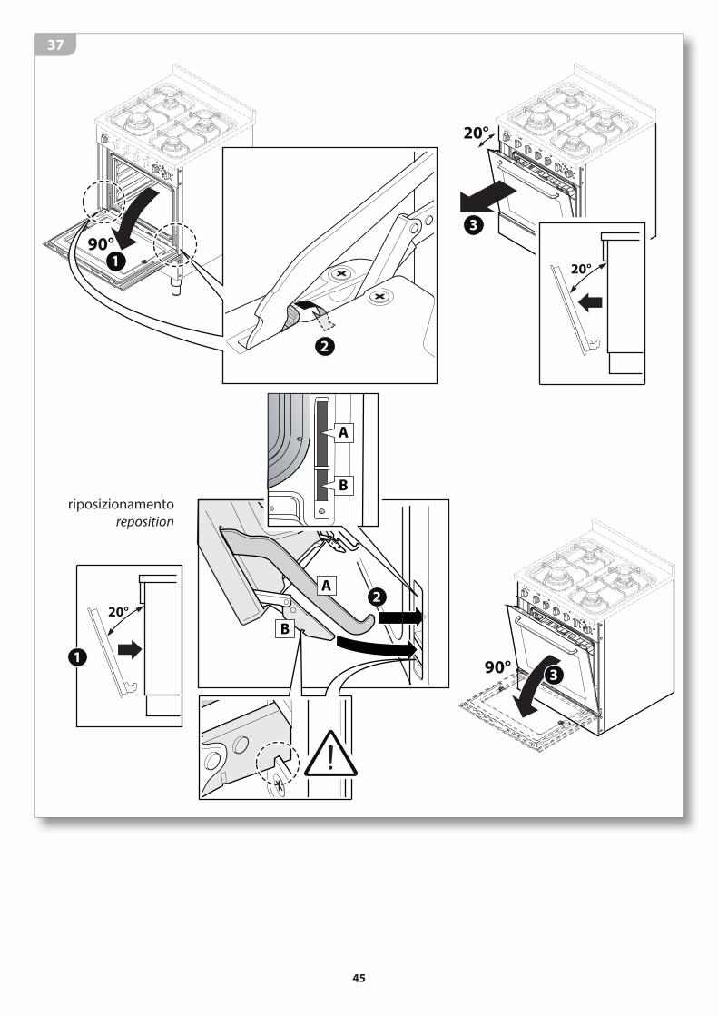
45
37
20°
3
20°
1
20°
90°1
2
B
A
2
90°3
A
B
2
riposizionamento
reposition

46
LAMP REPLACEMENT
Always switch off the main electrical switch
during routine maintenance or if the appliance will
not be used for an extended period.
Replace the lamp as indicated in fig. 38 with a lamp
resistant to high temperatures (minimum 300°C) with
the same characteristics, typology and dimensions.
Ensure that the appliance is switched off before replacing the lamp to avoid the possibility of electric shock.
PERIODS OF INACTIVITY
If the appliance will not be used for a long period of time
(more than 2-3 weeks):
• thoroughly clean the appliance following the instruc-
tions in the respective chapter;
• disconnect the electric power supply plug.
SOSTITUZIONE LAMPADINA
Chiudere sempre l’interruttore elettrico principale durante la manutenzione ordinaria o in caso di lunga inattività.
Sostituire la lampadina come indicato in fig. 38 con
una resistente alle alte temperature (minimo 300°C)
di pari caratteristiche, tipologia e dimensioni.
Assicurarsi che l’apparecchiatura sia scolle-
gata dalla rete di alimentazione prima di sostituire
la lampadina per evitare scariche elettriche.
(230V - E14)
38
PERIODI DI INATTIVITÀ
Se pensate di non utilizzare l’apparecchio per un lungo
periodo di tempo (superiore alle 2-3 settimane):
• effettuate un’accurata pulizia dell’apparecchiatura
seguendo quanto indicato nel capitolo dedicato;
• scollegate la spina di alimentazione elettrica.

47
SMALTIMENTO A FINE VITAIl simbolo del cestino barrato riportato sul prodotto indica che i Rifiuti derivanti dal-le Apparecchiature Elettriche ed Elettroni-che (RAEE) devono essere gestiti separa-tamente dal rifiuto indifferenziato, così da
essere sottoposti ad apposite operazioni per il loro riutilizzo, oppure a uno specifico trattamento per rimuovere e smaltire in modo sicuro le eventuali sostanze dannose per l’ambiente ed estrarre le materie prime che possono essere riciclate. In Italia i RAEE devono perciò essere conferiti nei
Centri di Raccolta dedicati. Quando si acquista una
nuova apparecchiatura, inoltre, si può consegnare
il RAEE al negoziante, che è tenuto a ritirarlo gratu-
itamente. Lo smaltimento abusivo o non corretto
del prodotto comporta l’applicazione delle sanzioni
previste dalla corrente normativa di legge.
Se il prodotto si trova in un paese diverso dall’Italia è necessario attenersi alle normative vigenti nel proprio paese.
Rendere inutilizzabile l’apparecchiatura per lo smaltimento rimuovendo il cavo di alimentazione.
ASSISTENZA POST VENDITA
Barazza srl Vi assicura la massima collaborazione
nell’eventualità dovessero sorgere problemi tecnici o
qualunque altra necessità.
Procedura in caso di malfunzionamento
Prima di contattare il Centro di Assistenza più comodo
effettuare le seguenti operazioni:
• verificare che ci sia corrente elettrica;
• rilevare i dati dell’apparecchiatura dalla targa matri-
cola (posizione targa matricola - vedi pag. 12);
• reperire la data di acquisto dell’apparecchiatura.
Attenzione! In attesa della risoluzione del
problema è opportuno non utilizzare l’apparec-
chiatura e scollegarla dall’alimentazione elettrica.
Non tentate di riparare o modificare l’apparecchio
in nessuna delle sue parti: oltre a far decadere la
Garanzia, ciò può essere potenzialmente pericoloso.
Richiedere e pretendere che siano utilizzati
unicamente ricambi originali: l’utilizzo di com-
ponentistica diversa da quella fornita dal Co-
struttore fa decadere la Garanzia e può arrecare danni
alle persone e all’apparecchiatura stessa.
END-OF-LIFE DISPOSAL
Il simbolo del cestino barrato riportato sul
prodotto indica che i Rifiuti derivanti dalle
Apparecchiature Elettriche ed Elettroniche
(RAEE) devono essere gestiti separatamen-
te dal rifiuto indifferenziato, così da essere
sottoposti ad apposite operazioni per il loro riutilizzo,
oppure a uno specifico trattamento per rimuovere e
smaltire in modo sicuro le eventuali sostanze danno-
se per l’ambiente ed estrarre le materie prime che
possono essere riciclate.
In Italia i RAEE devono perciò essere conferiti nei Cen-
tri di Raccolta dedicati. Quando si acquista una nuova
apparecchiatura, inoltre, si può consegnare il RAEE al
negoziante, che è tenuto a ritirarlo gratuitamente.
Lo smaltimento abusivo o non corretto del prodotto
comporta l’applicazione delle sanzioni previste dalla
corrente normativa di legge.
Se il prodotto si trova in un paese diverso dall’I-talia è necessario attenersi alle normative vigen-ti nel proprio paese.
Before disposing of the appliance, render it unusable by removing the power cord.
AFTER-SALES SERVICE
Barazza srl ensures you the utmost collaboration in the
event of technical problems or for any other needs you
may have.
Procedure to follow if your appliance is malfunctioning
Before contacting your nearest Service Centre, do the
following:
• check that the appliance is supplied with power;
• obtain the appliance data from the data plate (for data
plate position - see page 12);
• find the appliance purchase date.
Attention! While waiting for resolution of the
problem, you should stop using the appliance and
disconnect it from the power supply. Do not attempt
to repair or modify the appliance in any of its parts:
in addition to voiding the Warranty, this may be
dangerous.
Request or demand that only original spare parts
be used: the use of components other than those
supplied by the manufacturer voids the Warranty
and may cause personal injuries or damage the applian-
ce.

Pro
get
to g
rafi
co A
rtli
ne
a
cod
.CJO
L r
ev.0
1-1
0.2
01
3
Barazza srl
31025 Sarano di S.Lucia di Piave (TV) ITALIA
Via Risorgimento, 14
Tel. +39 0438 62888
Fax +39 0438 64901
www.jollynox.it