![Riassunto Arte [Botticelli, Antonello, Mantegna, Bellini]](https://static.fdocumenti.com/doc/165x107/557210d5497959fc0b8dbf02/riassunto-arte-botticelli-antonello-mantegna-bellini.jpg)
BOTTICELLI BT A D813947 00100 02 11-02-19
24
D813947 00100_02 11-02-19 BOTTICELLI BT A 650 ISTRUZIONI D’USO E DI INSTALLAZIONE INSTALLATION AND USER’S MANUAL INSTRUCTIONS D’UTILISATION ET D’INSTALLATION INSTALLATIONS-UND GEBRAUCHSANLEITUNG INSTRUCCIONES DE USO Y DE INSTALACION GEBRUIKS- EN INSTALLATIEAANWIJZINGEN AUTOMAZIONI PER PORTE BASCULANTI E SEZIONALI AUTOMATION FOR OVERHEAD AND SECTIONAL GARAGE DOORS AUTOMATION POUR PORTES BASCULANTES ET SECTIONALES GARAGENTORANTRIEB FÜR SCHWING UND SEKTIONALTORE AUTOMATIZACIONES PARA PUERTAS BASCULANTE Y SECCIONALES AUTOMATISERINGEN VOOR KANTEL- EN SECTIEDEUREN Attenzione! Leggere attentamente le “Avvertenze” all’interno! Caution! Read “Warnings” inside carefully! Attention! Veuillez lire attentivement les Avertissements qui se trouvent à l’intérieur! Achtung! Bitte lesen Sie aufmerksam die „Hinweise“ im Inneren! ¡Atención¡ Leer atentamente las “Advertencias” en el interior! Let op! Lees de “Waarschuwingen” aan de binnenkant zorgvuldig!
Transcript of BOTTICELLI BT A D813947 00100 02 11-02-19

D81
3947
001
00_0
2 1
1-02
-19
BOTTICELLI BT A650
ISTRUZIONI D’USO E DI INSTALLAZIONEINSTALLATION AND USER’S MANUALINSTRUCTIONS D’UTILISATION ET D’INSTALLATIONINSTALLATIONS-UND GEBRAUCHSANLEITUNGINSTRUCCIONES DE USO Y DE INSTALACIONGEBRUIKS- EN INSTALLATIEAANWIJZINGEN
AUTOMAZIONI PER PORTE BASCULANTI E SEZIONALIAUTOMATION FOR OVERHEAD AND SECTIONAL GARAGE DOORSAUTOMATION POUR PORTES BASCULANTES ET SECTIONALESGARAGENTORANTRIEB FÜR SCHWING UND SEKTIONALTOREAUTOMATIZACIONES PARA PUERTAS BASCULANTE Y SECCIONALESAUTOMATISERINGEN VOOR KANTEL- EN SECTIEDEUREN
Attenzione! Leggere attentamente le “Avvertenze” all’interno! Caution! Read “Warnings” inside carefully! Attention! Veuillez lire attentivement les Avertissements qui se trouvent à l’intérieur!Achtung! Bitte lesen Sie aufmerksam die „Hinweise“ im Inneren! ¡Atención¡ Leer atentamente las “Advertencias” en el interior! Let op! Lees de “Waarschuwingen” aan de binnenkant zorgvuldig!
1 2
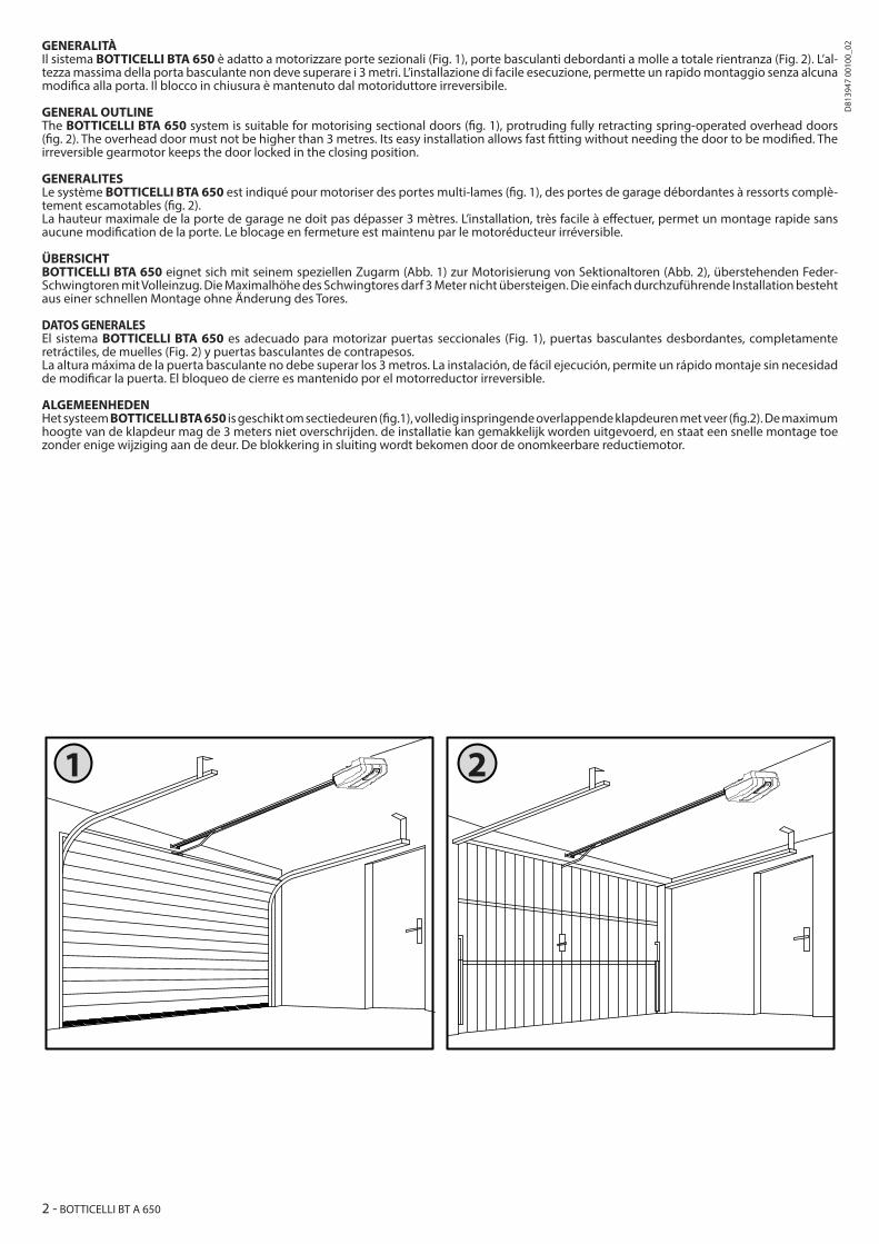
GENERALITÀIl sistema BOTTICELLI BTA 650 è adatto a motorizzare porte sezionali (Fig. 1), porte basculanti debordanti a molle a totale rientranza (Fig. 2). L’al-tezza massima della porta basculante non deve superare i 3 metri. L’installazione di facile esecuzione, permette un rapido montaggio senza alcuna modifica alla porta. Il blocco in chiusura è mantenuto dal motoriduttore irreversibile.
GENERAL OUTLINE The BOTTICELLI BTA 650 system is suitable for motorising sectional doors (fig. 1), protruding fully retracting spring-operated overhead doors (fig. 2). The overhead door must not be higher than 3 metres. Its easy installation allows fast fitting without needing the door to be modified. The irreversible gearmotor keeps the door locked in the closing position.
GENERALITES Le système BOTTICELLI BTA 650 est indiqué pour motoriser des portes multi-lames (fig. 1), des portes de garage débordantes à ressorts complè-tement escamotables (fig. 2).La hauteur maximale de la porte de garage ne doit pas dépasser 3 mètres. L’installation, très facile à effectuer, permet un montage rapide sans aucune modification de la porte. Le blocage en fermeture est maintenu par le motoréducteur irréversible.
ÜBERSICHTBOTTICELLI BTA 650 eignet sich mit seinem speziellen Zugarm (Abb. 1) zur Motorisierung von Sektionaltoren (Abb. 2), überstehenden Feder-Schwingtoren mit Volleinzug. Die Maximalhöhe des Schwingtores darf 3 Meter nicht übersteigen. Die einfach durchzuführende Installation besteht aus einer schnellen Montage ohne Änderung des Tores.
DATOS GENERALESEl sistema BOTTICELLI BTA 650 es adecuado para motorizar puertas seccionales (Fig. 1), puertas basculantes desbordantes, completamente retráctiles, de muelles (Fig. 2) y puertas basculantes de contrapesos. La altura máxima de la puerta basculante no debe superar los 3 metros. La instalación, de fácil ejecución, permite un rápido montaje sin necesidad de modificar la puerta. El bloqueo de cierre es mantenido por el motorreductor irreversible.
ALGEMEENHEDENHet systeem BOTTICELLI BTA 650 is geschikt om sectiedeuren (fig.1), volledig inspringende overlappende klapdeuren met veer (fig.2). De maximum hoogte van de klapdeur mag de 3 meters niet overschrijden. de installatie kan gemakkelijk worden uitgevoerd, en staat een snelle montage toe zonder enige wijziging aan de deur. De blokkering in sluiting wordt bekomen door de onomkeerbare reductiemotor.
2 - BOTTICELLI BT A 650
D81
3947
001
00_0
2
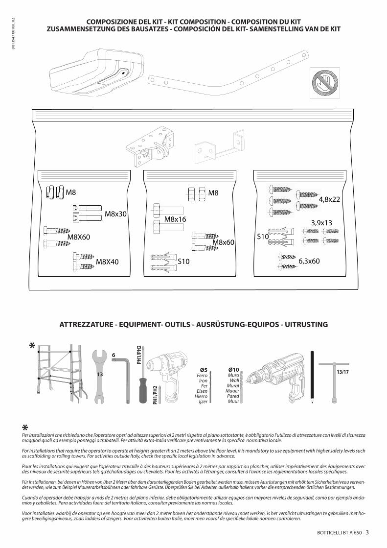
COMPOSIZIONE DEL KIT - KIT COMPOSITION - COMPOSITION DU KITZUSAMMENSETZUNG DES BAUSATZES - COMPOSICIÓN DEL KIT- SAMENSTELLING VAN DE KIT
Per installazioni che richiedano che l’operatore operi ad altezze superiori ai 2 metri rispetto al piano sottostante, è obbligatorio l’utilizzo di attrezzature con livelli di sicurezza maggiori quali ad esempio ponteggi o trabatelli. Per attività extra-Italia verificare preventivamente la specifica normativa locale.
For installations that require the operator to operate at heights greater than 2 meters above the floor level, it is mandatory to use equipment with higher safety levels such as scaffolding or rolling towers. For activities outside Italy, check the specific local legislation in advance.
Pour les installations qui exigent que l’opérateur travaille à des hauteurs supérieures à 2 mètres par rapport au plancher, utiliser impérativement des équipements avec des niveaux de sécurité supérieurs tels qu’échafaudages ou chevalets. Pour les activités à l’étranger, consulter à l’avance les réglementations locales spécifiques.
Für Installationen, bei denen in Höhen von über 2 Meter über dem darunterliegenden Boden gearbeitet werden muss, müssen Ausrüstungen mit erhöhtem Sicherheitsniveau verwen-det werden, wie zum Beispiel Maurerarbeitsbühnen oder fahrbare Gerüste. Überprüfen Sie bei Arbeiten außerhalb Italiens vorher die entsprechenden örtlichen Bestimmungen.
Cuando el operador debe trabajar a más de 2 metros del plano inferior, debe obligatoriamente utilizar equipos con mayores niveles de seguridad, como por ejemplo anda-mios y caballetes. Para actividades fuera del territorio italiano, consultar previamente las normas locales.
Voor installaties waarbij de operator op een hoogte van meer dan 2 meter boven het onderstaande niveau moet werken, is het verplicht uitrustingen te gebruiken met ho-gere beveiligingsniveaus, zoals ladders of steigers. Voor activiteiten buiten Italië, moet men vooraf de specifieke lokale normen controleren.
Ø5 Ferro
IronFer
EisenHierro
Ijzer
Ø10 Muro
WallMural
MauerParedMuur
ATTREZZATURE - EQUIPMENT- OUTILS - AUSRÜSTUNG-EQUIPOS - UITRUSTING
*
*
13
6
PH1/
PH2
PH1/
PH2
13/17
S10
M8 M8
M8x16
S10
M8x30
M8X60
M8X40
M8x60
4,8x22
3,9x13
6,3x60
BOTTICELLI BT A 650 - 3
D81
3947
001
00_0
2

200 mm
200 mm
108÷
116
mm
>116
mm
A
145°~
Installazione motore con soffitto STANDARD , Motor installation on STANDARD ceiling,Installation moteur sur plafond STANDARDInstallation Motor mit STANDARD-Abdeckung, Instalación del motor con techo ESTÁNDAR, Installatie motor met STANDAARD plafond
Installazione motore con soffitto PIU’ ALTO (prolunga) , Motor installation on HIGHER ceiling (with extension)Installation moteur sur plafond avec hauteur SUPERIEURE (avec rallonge), Installation Motor mit HÖHERER Abdeckung (Verlängerung) , Instalación del motor con techo MÁS ALTO (alargador), Installatie motor met HOGERE plafond (verlengstuk)
Si consiglia di fissare l’operatore in maniera tale da poter tenere il ramo anteriore della leva il più possibile orizzontale (vedere figura), fermo restando che andrà veri-ficato, da parte dell’installatore, il rispetto della normativa riguardante gli impatti.
It is suggested that the operator be set so that the front branch of the lever is as horizontal as possible (see figure), considering in any case that the installer must verify that the regulation concerning impacts must be complied with.
Il est recommandé de fixer l’opérateur de manière à pouvoir maintenir la branche avant du levier dans une position la plus horizontale que possible (voir figure), étant entendu que l’installateur vérifiera le respect de la norme concernant les impacts.
Es wird empfohlen den Bediener in einer solchen Weise zu sichern, dass der vordere Teil des Hebels so horizontal wie möglich (siehe Abbildung) gehalten wird. Dabei bleibt durch den Installateur zu prüfen, dass die Rechtsvorschrif-ten bezüglich der Anlagen eingehalten werden.
Se sugiere fijar el operador de modo que se pueda mantener el tramo delantero de la palanca lo más horizontal que sea posible (ver la figura), sin perjuicio de que el instalador deberá controlar que cumpla con la normativa sobre los impactos.
Er wordt aanbevolen om de operator zo te bevestigen dat de voorste arm van de hendel zo horizontaal mogelijk kan worden gehouden (zie afbeelding), op voorwaarde dat de installateur controleert dat de wetgeving met betrekking tot de impact wordt nageleefd.
*Non in dotazioneNot suppliedNe sont pas fournisNicht im lieferumNo asignadas en el equipamiento baseNiet meegeleverd
*Non in dotazioneNot suppliedNe sont pas fournisNicht im lieferumNo asignadas en el equipamiento baseNiet meegeleverd
BILANCIARE IL SEZIONALE!Balance the sectional door!Équilibrer la section !Die Motorgewichte ausgleichen!¡Equilibrar el seccional!Breng de sectionaaldeur in evenwicht!
BILANCIARE IL SEZIONALE!Balance the sectional door!Équilibrer la section !Die Motorgewichte ausgleichen!¡Equilibrar el seccional!Breng de sectionaaldeur in evenwicht!
4 - BOTTICELLI BT A 650
D81
3947
001
00_0
2

z
y
OK
1 2 3
4 5 617 mm
18 mm
4
8
B
C
OK
zz
z
y
y
3200 / 3800
33.5
2840 / 3440215
44.5
3150 / 3750
127
127
2290 / 2890* 50
2325 / 2925* 80
331
2142905 / 3505
115
115
z
66,5
PH1
ASSEMBLAGGIO BINARIO - RAIL ASSEMBLY -ASSEMBLAGE RAIL - GLEISMONTAGEENSAMBLADO DEL RIEL - MONTAGE SPOOR
Binario unicoSingle rail, RAIL uniqueEinteiliges Gleis, Riel único,Enkel spoor
Binario due pezziTwo piece railRail deux piècesZweiteiliges GleisRiel de dos piezasSpoor twee delen
Catena, Chain, ChaîneKette, Cadena, Ketting
cinghia, belt, courroieRiemen, correa, riem
DIMENSIONI - DIMENSIONS - DIMENSIONS -ABMESSUNGEN - DIMENSIONES - AFMETINGEN
* corsa utile/ usable travel /course utile / nutzhub/ carrera útil / werkslag
Nuove, new, nouveauneu, nuevo, nieuw
Nuove, new, nouveauneu, nuevo, nieuw
vecchie, old, anciensalt, viejo, oud
BOTTICELLI BT A 650 - 5
D81
3947
001
00_0
2
Ø10
13 mm
D
Ø10 mm
Ø10 mm Ø10 mm
**
**
**
**
E1
E2
60
6,3
Ø10
mm
Ø10
mmF1
8
D1
60
8
V1
16
8
V2
V1
V2
V2
D1F1
13
*
PH2
Ø10
mm
48 m
m
Ø10
mm
PH2
Ø10
mm
= =
PH2
13 mm
13max5,5 mm
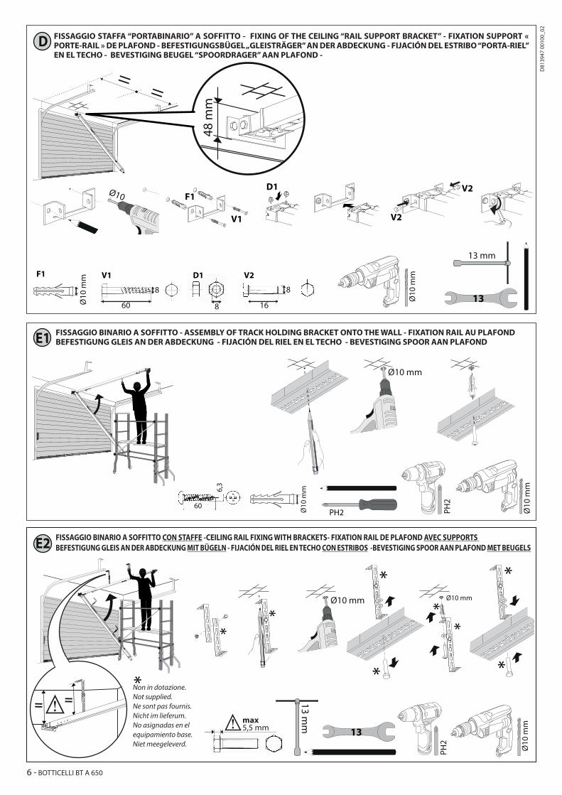
FISSAGGIO STAFFA “PORTABINARIO” A SOFFITTO - FIXING OF THE CEILING “RAIL SUPPORT BRACKET” - FIXATION SUPPORT « PORTE-RAIL » DE PLAFOND - BEFESTIGUNGSBÜGEL „GLEISTRÄGER” AN DER ABDECKUNG - FIJACIÓN DEL ESTRIBO “PORTA-RIEL” EN EL TECHO - BEVESTIGING BEUGEL “SPOORDRAGER” AAN PLAFOND -
FISSAGGIO BINARIO A SOFFITTO - ASSEMBLY OF TRACK HOLDING BRACKET ONTO THE WALL - FIXATION RAIL AU PLAFONDBEFESTIGUNG GLEIS AN DER ABDECKUNG - FIJACIÓN DEL RIEL EN EL TECHO - BEVESTIGING SPOOR AAN PLAFOND
FISSAGGIO BINARIO A SOFFITTO CON STAFFE -CEILING RAIL FIXING WITH BRACKETS- FIXATION RAIL DE PLAFOND AVEC SUPPORTS BEFESTIGUNG GLEIS AN DER ABDECKUNG MIT BÜGELN - FIJACIÓN DEL RIEL EN TECHO CON ESTRIBOS -BEVESTIGING SPOOR AAN PLAFOND MET BEUGELS
Non in dotazione.Not supplied.Ne sont pas fournis.Nicht im lieferum.No asignadas en elequipamiento base.Niet meegeleverd.
6 - BOTTICELLI BT A 650
D81
3947
001
00_0
2

30
8V3
F
G
H
1
2
4
3
31
60
8
8
V1
V1
V1
V2
8
40
V2
V3
V3
D1D1
D1
V2
2
V1 4,8
25 V2 3,5
25
2
V1
3V2
3,9
13
V1 V2
25
4,8
13
PH2 PH1
PH1
PH2
6
Ø 5
mm
PH2
PH2
1
Ø5
ASSEMBLAGGIO BRACCIO TRAINO - ASSEMBLY OF TRACK ONTO THE TRACK HOLDING BRACKET - ASSEMBLAGE BRAS ENTRAINEMENTMONTAGE SCHLEPPARM - ENSAMBLADO DEL BRAZO DE ARRASTRE - MONTAGE SLEEPARM
MONTAGGIO TESTA A BINARIO - HEAD ASSEMBLY TO RAIL - MONTAGE TÊTE À RAIL -MONTAGE KOPF AN GLEIS MONTAJE DEL CABEZAL AL RIEL - MONTAGE KOP OP SPOOR
INSTALLAZIONI PARTICOLARI CON TESTA RUOTATA - PARTICULAR INSTALLATIONS WITH ROTATED HEADINSTALLATIONS PARTICULIÈRES AVEC TÊTE TOURNÉE-BESONDERE INSTALLATIONEN MIT GESCHWENKTEM KOPFINSTALACIONES ESPECIALES CON CABEZAL GIRADO-BIJZONDERE INSTALLATIES MET GEDRAAIDE KOP
Per installazioni della testa a 90°, montare la testa al binario prima di montare il binario al soffitto.For 90° head installations, mount the head to the rail before mounting the rail to the ceiling.Pour les installations de la tête à 90°, monter la tête sur le rail avant de fixer le rail au plafond.Montieren Sie bei Installationen des Kopfes bei 90° den Kopf am Gleis, bevor Sie das Gleis an der. Para instalar el cabezal a 90°, montar el cabezal al riel, antes de montar el riel en el techo. Voor installaties van de kop op 90°, monteer de kop op het spoor alvorens het spoor op het plafond te monteren.
BOTTICELLI BT A 650 - 7
D81
3947
001
00_0
2
134,2
12
4
. . . . . .
. . . . . .
. . . . . .
. . . . . .
KO
>30 s
>30 s
>30 s
KO
KO
KO
OK
5 s
OK3
HI
fast
PH2
*
**
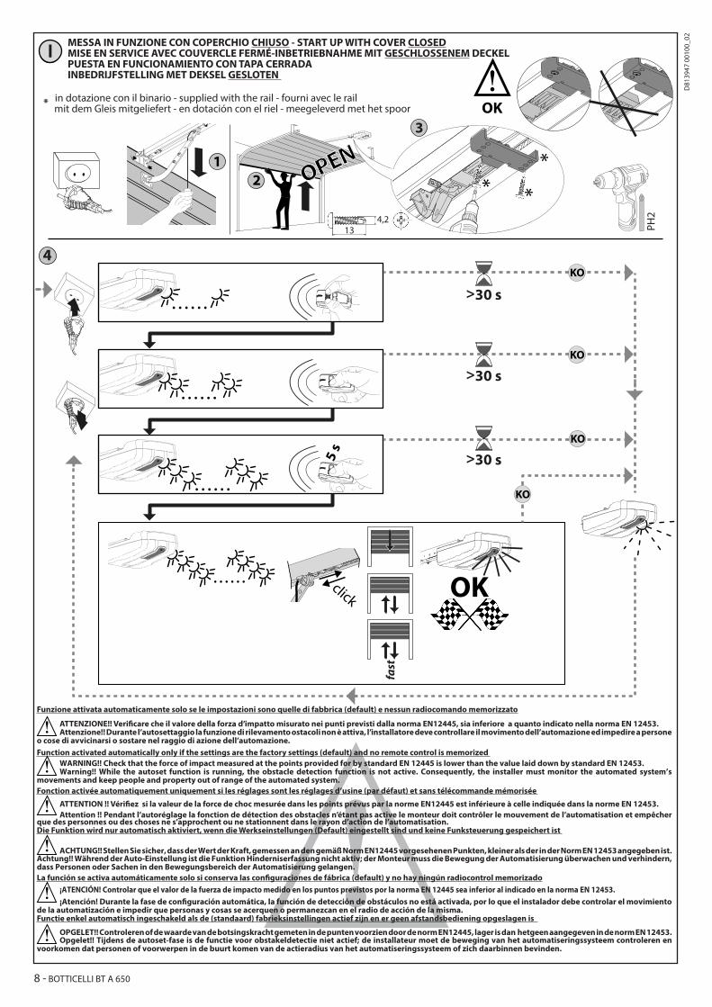
MESSA IN FUNZIONE CON COPERCHIO CHIUSO - START UP WITH COVER CLOSEDMISE EN SERVICE AVEC COUVERCLE FERMÉ-INBETRIEBNAHME MIT GESCHLOSSENEM DECKEL PUESTA EN FUNCIONAMIENTO CON TAPA CERRADAINBEDRIJFSTELLING MET DEKSEL GESLOTEN
Funzione attivata automaticamente solo se le impostazioni sono quelle di fabbrica (default) e nessun radiocomando memorizzato
ATTENZIONE!! Verificare che il valore della forza d’impatto misurato nei punti previsti dalla norma EN12445, sia inferiore a quanto indicato nella norma EN 12453.Attenzione!! Durante l’autosettaggio la funzione di rilevamento ostacoli non è attiva, l’installatore deve controllare il movimento dell’automazione ed impedire a persone
o cose di avvicinarsi o sostare nel raggio di azione dell’automazione. Function activated automatically only if the settings are the factory settings (default) and no remote control is memorized
WARNING!! Check that the force of impact measured at the points provided for by standard EN 12445 is lower than the value laid down by standard EN 12453.Warning!! While the autoset function is running, the obstacle detection function is not active. Consequently, the installer must monitor the automated system’s
movements and keep people and property out of range of the automated system.Fonction activée automatiquement uniquement si les réglages sont les réglages d’usine (par défaut) et sans télécommande mémorisée
ATTENTION !! Vérifiez si la valeur de la force de choc mesurée dans les points prévus par la norme EN12445 est inférieure à celle indiquée dans la norme EN 12453.Attention !! Pendant l’autoréglage la fonction de détection des obstacles n’étant pas active le monteur doit contrôler le mouvement de l’automatisation et empêcher
que des personnes ou des choses ne s’approchent ou ne stationnent dans le rayon d’action de l’automatisation.Die Funktion wird nur automatisch aktiviert, wenn die Werkseinstellungen (Default) eingestellt sind und keine Funksteuerung gespeichert ist
ACHTUNG!! Stellen Sie sicher, dass der Wert der Kraft, gemessen an den gemäß Norm EN12445 vorgesehenen Punkten, kleiner als der in der Norm EN 12453 angegeben ist.Achtung!! Während der Auto-Einstellung ist die Funktion Hinderniserfassung nicht aktiv; der Monteur muss die Bewegung der Automatisierung überwachen und verhindern, dass Personen oder Sachen in den Bewegungsbereich der Automatisierung gelangen. La función se activa automáticamente solo si conserva las configuraciones de fábrica (default) y no hay ningún radiocontrol memorizado
¡ATENCIÓN! Controlar que el valor de la fuerza de impacto medido en los puntos previstos por la norma EN 12445 sea inferior al indicado en la norma EN 12453.¡Atención! Durante la fase de configuración automática, la función de detección de obstáculos no está activada, por lo que el instalador debe controlar el movimiento
de la automatización e impedir que personas y cosas se acerquen o permanezcan en el radio de acción de la misma.Functie enkel automatisch ingeschakeld als de (standaard) fabrieksinstellingen actief zijn en er geen afstandsbediening opgeslagen is
OPGELET!! Controleren of de waarde van de botsingskracht gemeten in de punten voorzien door de norm EN12445, lager is dan hetgeen aangegeven in de norm EN 12453.Opgelet!! Tijdens de autoset-fase is de functie voor obstakeldetectie niet actief; de installateur moet de beweging van het automatiseringssysteem controleren en
voorkomen dat personen of voorwerpen in de buurt komen van de actieradius van het automatiseringssysteem of zich daarbinnen bevinden.
* in dotazione con il binario - supplied with the rail - fourni avec le rail mit dem Gleis mitgeliefert - en dotación con el riel - meegeleverd met het spoor
8 - BOTTICELLI BT A 650
D81
3947
001
00_0
2
HL
JP2
1 AT
JP724V
21 TX1 2
1RX1
45
3
50 51 70 73
24V
21 TX1 2
1RX1
45
3
50 51 52 70 73D3=ON
D3=OFF
(1TX + 1RX)
(1TX + 1RX)
24V
-24
V +
24 V
Safe
+
IC 1
IC 2
NONO
SAFE
1
STO
PCO
M
SAFE
2
NCNCNC
*
*
*
73 72 71 62 61 51 27 266070
5221
5020
Fig. L2
24V0V
70 72D2=OFF
D2=ON
50 51 52
56
32151
5070
7251
4
7072
8,2K
ohm
5%
SAFETY EDGE SAFETY EDGE
BAR
70 72
Fig. L1
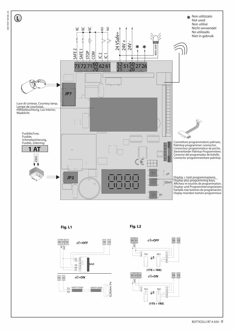
Luce di cortesia, Courtesy lamp,Lampe de courtoisie,Hilfsbeleuchtung, Luz interior, Waaklicht.
Connettore programmatore palmare,Palmtop programmer connector,Connecteur programmateur de poche,Steckverbinder Palmtop-Programmierer,Conector del programador de bolsillo,Connector programmeerbare palmtop.
Fusibile,Fuse,Fusible,Schmelzsicherung,Fusible, Zekering:
Display + tasti programmazione,Display plus programming keys,Afficheur et touches de programmation, Display und Programmierungstasten, Pantalla más botones de programación, Display meerdere toetsen programmeur.
Non utilizzatoNot used Non utilisé Nicht verwendetNo utilizado Niet in gebruik
BOTTICELLI BT A 650 - 9
D81
3947
001
00_0
2
ITALIANOMorsetto Definizione Descrizione
Alim
en-
tazi
one
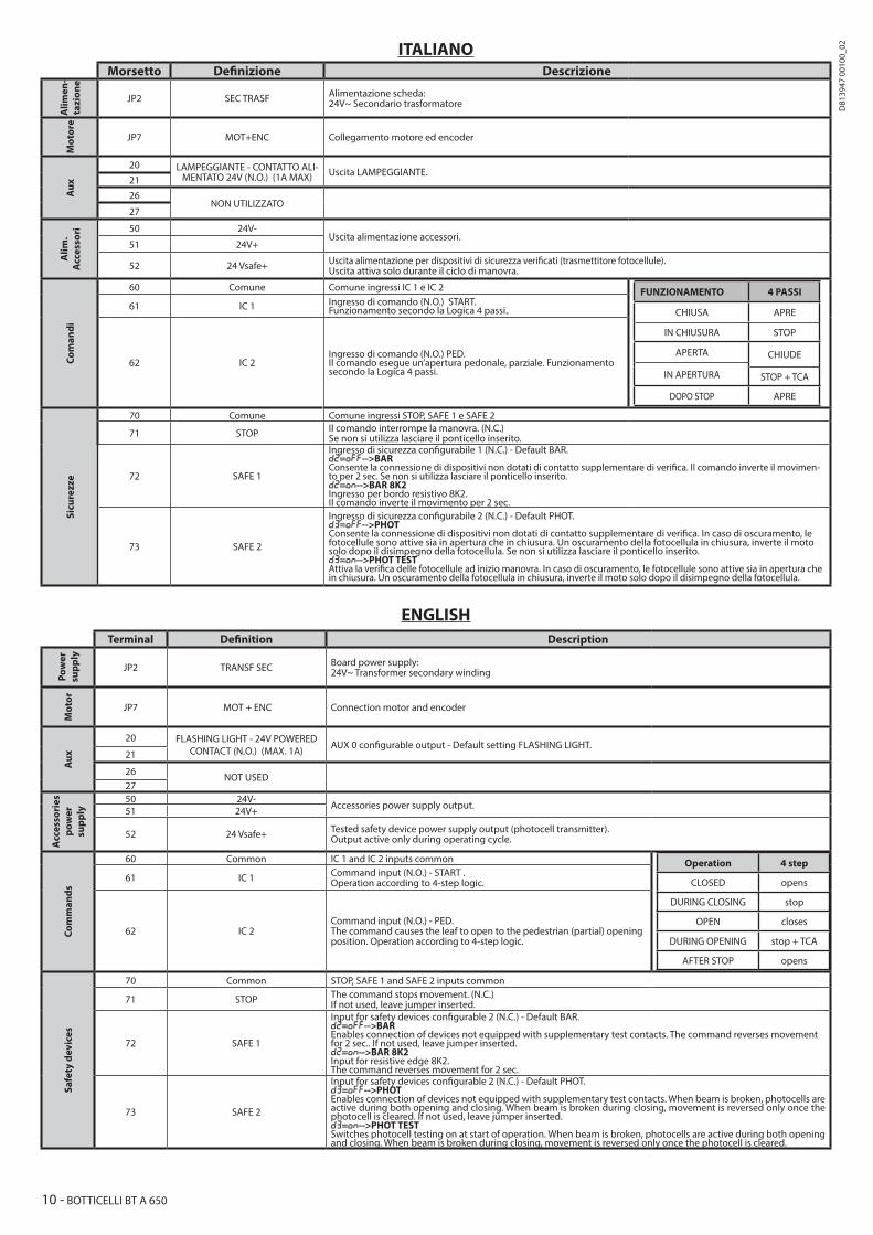
JP2 SEC TRASF Alimentazione scheda: 24V~ Secondario trasformatore
Mot
ore
JP7 MOT+ENC Collegamento motore ed encoder
Aux
20 LAMPEGGIANTE - CONTATTO ALI-MENTATO 24V (N.O.) (1A MAX) Uscita LAMPEGGIANTE.
2126
NON UTILIZZATO27
Alim
.A
cces
sori 50 24V-
Uscita alimentazione accessori.51 24V+
52 24 Vsafe+ Uscita alimentazione per dispositivi di sicurezza verificati (trasmettitore fotocellule). Uscita attiva solo durante il ciclo di manovra.
Com
andi
60 Comune Comune ingressi IC 1 e IC 2 FUNZIONAMENTO 4 PASSI
CHIUSA APRE
IN CHIUSURA STOP
APERTA CHIUDE
IN APERTURA STOP + TCA
DOPO STOP APRE
61 IC 1 Ingresso di comando (N.O.) START.Funzionamento secondo la Logica 4 passi..
62 IC 2Ingresso di comando (N.O.) PED. Il comando esegue un’apertura pedonale, parziale. Funzionamento secondo la Logica 4 passi.
Sicu
rezz
e
70 Comune Comune ingressi STOP, SAFE 1 e SAFE 2
71 STOP Il comando interrompe la manovra. (N.C.) Se non si utilizza lasciare il ponticello inserito.
72 SAFE 1
Ingresso di sicurezza configurabile 1 (N.C.) - Default BAR. d2=OFF-->BARConsente la connessione di dispositivi non dotati di contatto supplementare di verifica. Il comando inverte il movimen-to per 2 sec. Se non si utilizza lasciare il ponticello inserito.d2=On-->BAR 8K2Ingresso per bordo resistivo 8K2. Il comando inverte il movimento per 2 sec.
73 SAFE 2
Ingresso di sicurezza configurabile 2 (N.C.) - Default PHOT. d3=OFF-->PHOT Consente la connessione di dispositivi non dotati di contatto supplementare di verifica. In caso di oscuramento, le fotocellule sono attive sia in apertura che in chiusura. Un oscuramento della fotocellula in chiusura, inverte il moto solo dopo il disimpegno della fotocellula. Se non si utilizza lasciare il ponticello inserito.d3=On-->PHOT TEST Attiva la verifica delle fotocellule ad inizio manovra. In caso di oscuramento, le fotocellule sono attive sia in apertura che in chiusura. Un oscuramento della fotocellula in chiusura, inverte il moto solo dopo il disimpegno della fotocellula.
ENGLISHTerminal Definition Description
Pow
er
supp
ly
JP2 TRANSF SEC Board power supply: 24V~ Transformer secondary winding
Mot
or
JP7 MOT + ENC Connection motor and encoder
Aux
20 FLASHING LIGHT - 24V POWERED CONTACT (N.O.) (MAX. 1A) AUX 0 configurable output - Default setting FLASHING LIGHT.
21
26 NOT USED27
Acc
esso
ries
pow
er
supp
ly
50 24V-Accessories power supply output.51 24V+
52 24 Vsafe+ Tested safety device power supply output (photocell transmitter). Output active only during operating cycle.
Com
man
ds
60 Common IC 1 and IC 2 inputs common Operation 4 step
CLOSED opens
DURING CLOSING stop
OPEN closes
DURING OPENING stop + TCA
AFTER STOP opens
61 IC 1 Command input (N.O.) - START . Operation according to 4-step logic.
62 IC 2Command input (N.O.) - PED. The command causes the leaf to open to the pedestrian (partial) opening position. Operation according to 4-step logic.
Safe
ty d
evic
es
70 Common STOP, SAFE 1 and SAFE 2 inputs common
71 STOP The command stops movement. (N.C.) If not used, leave jumper inserted.
72 SAFE 1
Input for safety devices configurable 2 (N.C.) - Default BAR. d2=OFF-->BAREnables connection of devices not equipped with supplementary test contacts. The command reverses movement for 2 sec.. If not used, leave jumper inserted.d2=On-->BAR 8K2 Input for resistive edge 8K2. The command reverses movement for 2 sec.
73 SAFE 2
Input for safety devices configurable 2 (N.C.) - Default PHOT. d3=OFF-->PHOT Enables connection of devices not equipped with supplementary test contacts. When beam is broken, photocells are active during both opening and closing. When beam is broken during closing, movement is reversed only once the photocell is cleared. If not used, leave jumper inserted.d3=On-->PHOT TEST Switches photocell testing on at start of operation. When beam is broken, photocells are active during both opening and closing. When beam is broken during closing, movement is reversed only once the photocell is cleared.
10 - BOTTICELLI BT A 650
D81
3947
001
00_0
2

FRANÇAISBorne Définition Description
Alim
en-
tati
on JP2 SEC TRANSF Alimentation de la carte: 24V~Secondaire transformateur
Mot
eur
JP7 MOT + ENC Connexion moteur et encoder
Aux
20 CLIGNOTANT - CONTATTO ALIMEN-TATO 24V (N.O.) (1A MAX) Sortie CLIGNOTANT
2126
NON UTILISÉ27
Alim
enta
tion
de
s ac
cess
oire
s 50 24V-Sortie alimentation accessoires.
51 24V+
52 24 Vsafe+ Sortie alimentation des dispositifs de sécurité vérifiés (émetteur photocellules et émetteur linteau sensible) Sortie active uniquement pendant le cycle de manœuvre.
Com
man
des
60 Commun Commun entrées IC 1 et IC 2 Fonctionnement 4 PAS
FERMÉE OUVRE
EN FERMETURE STOP
OUVERTE FERME
EN OUVERTURE STOP + TCA
APRÈS STOP OUVRE
61 IC 1 Entrée de commande (N.O.) - START Fonctionnement suivant la Logique 4 PAS
62 IC 2Entrée de commande (N.O.) - PED. La commande accomplit une ouverture piétonne, partielle. Fonctionnement suivant la logique 4 PAS.
Sécu
rité
s
70 Commun Commun entrées STOP, SAFE 1 et SAFE 2
71 STOP La commande interrompt la manœuvre. (N.F.) Si vous ne l’utilisez pas, laissez la barrette en place.
72 SAFE 1
Entrée de sécurité configurable 1 (N.F.) - Défaut PHOTd2=OFF-->BARPermet de connecter les dispositifs dépourvus de contact supplémentaire de vérification. La commande inverse le mouvement pendant 2s. Si vous ne l’utilisez pas, laissez la barrette en placed2=On-->BAR 8K2 Entrée pour linteau résistif 8K2. La commande inverse le mouvement pendant 2 secondes.
73 SAFE 2
Entrée de sécurité configurable 2 (N.F.) - Défaut BAR. d3=OFF-->PHOT Permet de connecter les dispositifs dépourvus de contact supplémentaire de vérification. En cas d’obscurcissement, les photocellules sont actives en ouverture et en fermeture. Un obscurcissement de la photocellule en fermeture n’inverse le mouvement que lorsque la photocellule est libérée. Si vous ne l’utilisez pas, laissez la barrette en place.d3=On-->PHOT TEST Active la vérification des photocellules au début de la manoeuvre. En cas d’obscurcissement, les photocellules sont actives en ouverture et en fermeture. Un obscurcissement de la photocellule en fermeture inverse le mouvement uniquement après le dégagement de la photocellule.
DEUTSCH
Klemme Definition Beschreibung
Stro
m-
vers
or-
gung JP2 SEK TRASF Stromversorgungsdatenblatt:
24V~ Sekundärer Transformator
Mot
or
JP7 MOT+ENC Motor- und Encoderanschluss
Aux
20 BLINKEND - GESPEISTER KON-TAKT 24V (N.O.) (1A MAX) BLINKENDER Ausgang.
2126
NICHT VERWENDET27
Stro
mve
rs.
Zube
hör 50 24V-
Ausgang Stromversorgung Zubehör.51 24V+
52 24 Vsafe+ Stromversorgungsausgang für geprüfte Sicherheitsvorrichtungen (Fotozellensender).Ausgang nur während des Manöverzyklus aktiv
Befe
hle
60 Sammel Sammeleingänge IC 1 und IC 2 Bestimmungen 4-SCHRITT
GESCHLOSSEN ÖFFNUNG
BEI SCHLIESSUNG STOPP
OFFEN SCHLIESSUNG
BEI ÖFFNUNG STOPP+ TCA
NACH STOP ÖFFNUNG
61 IC 1 Befehlseingabe (N.O.) START.Funktionsweise gemäß der 4-Schritt-Logik..
62 IC 2Befehlseingabe (N.O.) PED.Der Befehl führt eine teilweise Öffnung für Fußgänger durch. Funktionsweise gemäß der 4-Schritt-Logik.
Sich
erhe
it
70 Sammel Sammeleingänge STOP, SAFE 1 und SAFE 2
71 STOP Der Befehl unterbricht das Manöver. (N.C.)Wenn nicht verwendet, die Überbrückung eingeschaltet lassen.
72 SAFE 1
Konfigurierbarer Sicherheitseingang 1 (N.C.) - Default BAR.d2=OFF-->BARErlaubt den Anschluss von Vorrichtungen ohne zusätzlichen Prüfkontakt. Der Befehl kehrt die Bewegung für 2 Sek. um. Wenn nicht verwendet, die Überbrückung eingeschaltet lassen.d2=On-->BAR 8K2Eingang für Widerstandsrahmen 8K2. Der Befehl kehrt die Bewegung für 2 Sek. um.
73 SAFE 2
Konfigurierbarer Sicherheitseingang 2 (N.C.) - Default PHOT. d3=OFF-->PHOT Erlaubt den Anschluss von Vorrichtungen ohne zusätzlichen Prüfkontakt. Bei einer Abdunklung sind die Fotozellen sowohl beim Öffnen als auch beim Schließen aktiv. Eine Abdunklung der sich schließenden Fotozelle kehrt die Bewegung nur um, nachdem die Fotozelle gelöst wurde. Wenn nicht verwendet, die Überbrückung eingeschaltet lassen.d3=On-->PHOT TEST Aktivieren Sie die Überprüfung der Fotozellen zu Beginn des Manövers. Bei einer Abdunklung sind die Fotozellen sowohl beim Öffnen als auch beim Schließen aktiv. Eine Abdunklung der sich schließenden Fotozelle kehrt die Bewegung nur um, nachdem die Fotozelle gelöst wurde.
BOTTICELLI BT A 650 - 11
D81
3947
001
00_0
2

ESPAÑOL
Terminal Definición DescripciónA
limen
-ta
ción
JP2 SEC TRASF Alimentación tarjeta: 24 V~ Secundario transformador
Mot
or
JP7 MOT+ENC Conexión motor y encoder
Aux
20 INTERMITENTE - CONTACTO ALI-MENTADO 24 V (N.A.) (1 A MÁX) Salida INTERMITENTE.
2126
NO UTILIZADO27
Alim
.A
cces
orio
s 50 24V-Salida alimentación de los accesorios.
51 24V+
52 24 Vsafe+ Salida alimentación para dispositivos de seguridad verificados (transmisor de células fotoeléctricas).Salida activa solo durante el ciclo de maniobra.
Man
dos
60 Común Común entradas IC 1 e IC 2 FUNCIONAMIENTO 4 PASOS
CERRADA ABRE
EN FASE DE CIERRE STOP
ABIERTA CIERRA
EN FASE DE APERTURA STOP + TCA
DESPUÉS DE STOP ABRE
61 IC 1 Entrada del mando (N.A.) START.Funcionamiento según la lógica 4 pasos.
62 IC 2Entrada del mando (N.A.) PED.El comando ejecuta una apertura peatonal parcial. Funcionamiento según la lógica 4 pasos.
Med
idas
de
segu
rida
d
70 Común Común entradas STOP, SAFE 1 y SAFE 2
71 STOP El mando interrumpe la maniobra. (N.C.)Si no se utiliza, dejar el puente conectado.
72 SAFE 1
Entrada de seguridad configurable 1 (N.C.) - Default BAR.d2=OFF-->BARPermite conectar dispositivos que no tienen el contacto adicional de control. El mando invierte el movimiento durante 2 segundos. Si no se utiliza, dejar el puente conectado.d2=On-->BAR 8K2Entrada para borde resistivo 8K2. El mando invierte el movimiento durante 2 segundos.
73 SAFE 2
Entrada de seguridad configurable 2 (N.C.) - Default PHOT. d3=OFF-->PHOT Permite conectar dispositivos que no tienen el contacto adicional de control. En caso de interrupción, se activan las células fotoeléctricas tanto en apertura como en cierre. Si se interrumpe la célula fotoeléctrica durante el cierre, solo invierte el movimiento cuando se libera la célula fotoeléctrica. Si no se utiliza, dejar el puente conectado.d3=On-->PHOT TEST
NEDERLANDSKlem Definitie Beschrijving
Voe-
ding JP2 SEC TRASF Toevoer kaart:
24V~ Secundaire transformator
Mot
or
JP7 MOT+ENC Verbinding motor en encoder
Aux
20 KNIPPERLICHT - CONTACT GEVO-ED 24V (N.O.) (1A MAX) Uitgang KNIPPERLICHT.
2126
NIET GEBRUIKT27
Toev
.A
cces
soir
es 50 24V-Uitgang toevoer accessoires.
51 24V+
52 24 Vsafe+ Uitgang voeding voor geverifieerde veiligheidsvoorzieningen (zender fotocellen).Uitgang enkel actief tijdens de bewegingscyclus.
Bbed
ieni
ngen
60 Gemeenschappelijk Gemeenschappelijk ingangen IC 1 en IC 2 WERKING 4-STAPS
GESLOTEN OPENT
BIJ SLUITING STOP
OPEN SLUIT
BIJ OPENING STOP + TCA
NA STOP OPENT
61 IC 1 Ingang commando (N.O.) START.Werking volgens Logica 4 stappen.
62 IC 2Ingang commando (N.O.) VOET.Het commando voert een gedeeltelijke voetgangersopening uit. Werking volgens Logica 4 stappen.
Beve
iligi
ngen
70 Gemeenschappelijk Gemeenschappelijk ingangen STOP, SAFE 1 en SAFE 2
71 STOP Het commando onderbreekt de beweging. (N.C.)Laat de brug verbonden indien ze niet gebruikt wordt.
72 SAFE 1
Configureerbare veiligheidsingang 1 (N.C.) - Default BAR.d2=OFF-->BARStaat de aansluiting toe van apparaten die niet voorzien zijn van bijkomende controlecontact. De bediening keert de beweging voor 2 sec om. Laat de brug verbonden indien ze niet gebruikt wordt.d2=On-->BAR 8K2Ingang voor resistieve rand 8K2. De bediening keert de beweging voor 2 sec om.
73 SAFE 2
Configureerbare veiligheidsingang 2 (N.C.) - Default PHOT. d3=OFF-->PHOT Staat de aansluiting toe van apparaten die niet voorzien zijn van bijkomende controlecontact. In geval van verduistering, zijn de fotocellen actief zowel bij opening als bij sluiting. Een verdonkering van de fotocel tijdens de sluiting, keert de beweging pas na vrijgave van de fotocel om. Laat de brug verbonden indien ze niet gebruikt wordt.d3=On-->PHOT TEST Hiermee activeert u de controle van de fotocellen aan het begin van de beweging. In geval van verduistering, zijn de fotocellen actief zowel bij opening als bij sluiting. Een verdonkering van de fotocel tijdens de sluiting, keert de beweging keert pas na vrijgave van de fotocel om.
12 - BOTTICELLI BT A 650
D81
3947
001
00_0
2

M
5s
auto . . . . . .
4
. . . . . .
KO
. . . . . .
fast
fast
134,2
12
OK3
PH2
*
**
*in dotazione con il binario - supplied with the rail - fourni avec le rail mit dem Gleis mitgeliefert - en dotación con el riel - meegeleverd met het spoor
ATTENZIONE!! Verificare che il valore della forza d’impatto misurato nei punti previsti dalla norma EN12445, sia inferiore a quanto indicato nella norma EN 12453.
Attenzione!! Durante l’autosettaggio la funzione di rilevamento ostacoli non è attiva, l’installatore deve controllare il movimento dell’automazione ed impedire a persone o cose di avvicinarsi o sostare nel raggio di azione dell’automazione.
WARNING!! Check that the force of impact measured at the points provided for by standard EN 12445 is lower than the value laid down by standard EN 12453.
Warning!! While the autoset function is running, the obstacle detection function is not active. Consequently, the installer must monitor the automated system’s movements and keep people and property out of range of the automated system.
ATTENTION !! Vérifiez si la valeur de la force de choc mesurée dans les points prévus par la norme EN12445 est inférieure à celle indiquée dans la norme EN 12453.
Attention !! Pendant l’autoréglage la fonction de détection des obstacles n’étant pas active le monteur doit contrôler le mouvement de l’automatisation et empêcher que des personnes ou des choses ne s’approchent ou ne stationnent dans le rayon d’action de l’auto-matisation.
ACHTUNG!! Stellen Sie sicher, dass der Wert der Kraft, gemessen an den gemäß Norm EN12445 vorgesehenen Punkten, kleiner als der in der Norm EN 12453 angegeben ist.Achtung!! Während der Auto-Einstellung ist die Funktion Hinderniserfassung nicht aktiv; der Monteur muss die Bewegung der Auto-matisierung überwachen und verhindern, dass Personen oder Sachen in den Bewegungsbereich der Automatisierung gelangen.
¡ATENCIÓN! Controlar que el valor de la fuerza de impacto medido en los puntos previstos por la norma EN 12445 sea inferior al indicado en la norma EN 12453.
¡Atención! Durante la fase de configuración automática, la función de detección de obstáculos no está activada, por lo que el instalador debe controlar el movimiento de la automatización e impedir que personas y cosas se acerquen o permanezcan en el radio de acción de la misma.
OPGELET!! Controleren of de waarde van de botsingskracht gemeten in de punten voorzien door de norm EN12445, lager is dan hetgeen aangegeven in de norm EN 12453.
Opgelet!! Tijdens de autoset-fase is de functie voor obstakeldetectie niet actief; de installateur moet de beweging van het automatise-ringssysteem controleren en voorkomen dat personen of voorwerpen in de buurt komen van de actieradius van het automatiserings-systeem of zich daarbinnen bevinden.
MESSA IN FUNZIONE - START-UP - MISE EN SERVICE - INBETRIEBNAHMEPUESTA EN FUNCIONAMIENTO - INBEDRIJFSTELLING
BOTTICELLI BT A 650 - 13
D81
3947
001
00_0
2

HP
HO
HN
2s o o o
<10 s
5sprg
<10 s
2s o o o
<10 s <10 s
1 2 3 4 5 6 7
10 s 10 s
o o
o o
STOP
ped
20%
PROGRAMMAZIONE TRASMETTITORI MANUALE - MANUAL TRANSMITTER PROGRAMMING -PROGRAMMATION MANUELLE ÉMETTEURS-MANUELLE SENDERPROGRAMMIERUNG-PROGRAMACIÓN MANUAL DE LOS TRANSMISORES-HANDMATIGE PROGRAMMERING ZENDERS
CANCELLAZIONE TRASMETTITORI - TRANSMITTERS CANCELLATION -ANNULATION DES ÉMETTEURSLÖSCHEN DER SENDER-ELIMINACIÓN TRANSMISORES-WISSEN ZENDERS
PROGRAMMAZIONE TRASMETTITORI REMOTA - REMOTE TRANSMITTER PROGRAMMING - PROGRAMMATION ÉMETTEURS À DISTANCE FERNPROGRAMMIERUNG DER SENDER-ROGRAMACIÓN A DISTANCIA DE LOS TRANSMISORES-PROGRAMMERING ZENDERS OP AFSTAND
---
trasemttitore già memorizzatotransmitter already memorized
émetteur déjà mémoriséSender bereits gespeichertTransmisor ya memorizadoReeds opgeslagen zender
trasemttitore da memorizzaretransmitter to be memorized
Émetteur à mémoriserSender zu speichern
Transmisor para memorizarZender die opgeslagen moet worden
Cancellazione in corsoCancellation in progress
Annulation en coursLöschen läuft
Eliminación en cursoWissen bezig
Cancellazione effettuataCancellation completed
Annulation effectuéeLöschen durchgeführtEliminación efectuada
Wissen uitgevoerd
ITALIANO
• Comando apertura• ≥ 2 sec Programmazione tra-smettitore manuale come start
• Comando chiusura• ≥ 2 sec Programmazione tra-smettitore manuale come 2° ca-nale radio
• ≥ 5 sec Cancellazione radio-comandi
• Accesso al menù• ≥ 5 sec menù autoset
ENGLISH
• Opening command• ≥ 2 sec Manual transmitter pro-gramming as start
• Closure command• ≥ 2 sec Manual transmitter pro-gramming as 2nd radio channel
• ≥ 5 sec Cancellation of remo-te controls
• Access menu• ≥ 5 sec menu autoset
FRANÇAIS
• Commande ouverture• ≥ 2 sec Programmation manuel-
le émetteur comme démarrage
• Commande fermeture• ≥ 2 sec Programmation manuelle
émetteur comme 2e canal radio
• ≥ 5 sec Suppression radio-commandes
• Accès au menu• ≥ 5 sec menu auto-configu-ration
14 - BOTTICELLI BT A 650
D81
3947
001
00_0
2

. . . . . . . .
5 s.
LEGENDA
HQ MENU
ParametroParameterParamètreParameterParámetroParameter
Accensione display/conferma
Switch on display/Confirm
Allumage afficheur / confirmation
Displayeinschaltung / Bestätigung
Encendido pantalla/Confirmación
Inschakeling display / bevestiging
Uscita menùExit MenuSortir du menuMenüausgangSalida menúUitgang menu
incrementoincreasedaugmentationErhöhungincrementovergroting
decrementodecreaseddiminutionAbsenkungdecrementodaling
ValoreValue Valeur
ValoreValue Valeur
Versione software centraleControl unit software versionVersion logiciel centraleZentrale SoftwareversionVersión software centralCentrale softwareversie
DEUTSCH
• Öffnungsbefehl• ≥ 2 Sek Manuelle Sender-
programmierung wie Start
• Schließbefehl• ≥ 2 Sek Manuelle Sender-
programmierung wie 2. Ra-diokanal
• ≥ 5 Sek Löschung Funk-steuerungen
• Zugang zum Menü• ≥ 5 Sek Autoeinstellungsmenü
NEDERLANDS
• Commando opening• ≥ 2 sec Programmering
handmatige zender als start
• Commando sluiting• ≥ 2 sec Programmering
handmatige zender als 2° radiokanaal
• ≥ 5 sec Wissen afstandsbe-dieningen
• Toegang tot menu• ≥ 5 sec menu autoset
ESPAÑOL
• Mando de apertura• ≥ 2 seg. Programación manual
del transmisor como start
• Mando de cierre• ≥ 2 seg. Programación manual del transmisor como 2° canal radio
• ≥ 5 seg. Eliminación de los radiocontroles
• Acceso al menú• ≥ 5 seg. Menú autoset
WertValor
Waarde
WertValor
Waarde
BOTTICELLI BT A 650 - 15
D81
3947
001
00_0
2

ITALIANOTABELLA “A” - MENU PARAMETRI - (para )
Logica Definizione Default Barrare il settaggio eseguito Opzioni
d1 Blocca Impulsi apertura OFFON L’impulso di start non ha alcun effetto durante la fase di apertura. OFF L’impulso di start ha effetto durante la fase di apertura.
d2 BAR/8K2 OFFON Ingresso configurato come Bar 8k2. Ingresso per bordo resistivo 8K2 (Fig. L1).
Il comando inverte il movimento per 2 sec.
OFF Ingresso configurato come Bar, costa sensibile.Il comando inverte il movimento per 2 sec.
d3 Test fotocellule OFFON Attiva la verifica delle fotocellule (Fig. L2)OFF Disattiva la verifica delle fotocellule
Parametro Min. Max. Default Personali Definizione Descrizione
T1 0 99 0 Tempo chiusura automatica [%]
0= chiusura automatica disabilitata1-99= imposta il valore del tempo di chiusura automatica tra 1% e 99% (corrisponde a 1s - 180s)
E’ obbligatorio installare una coppia di fotocellule se si abilita il funzionamento automatico
T2 1 99 75 Coppia apertura [%] Impostare il valore di coppia di apertura del motore tra 1% e 99%. *
T3 1 99 75 Coppia chiusura [%] Impostare il valore di coppia di chiusura del motore tra 1% e 99%. *
* ATTENZIONE: Verificare che il valore della forza d’impatto misurato nei punti previsti dalla norma EN12445, sia inferiore a quanto indicato nella norma EN 12453.Una errata impostazione della sensibilità può creare danni a persone, animali o cose.
ENGLISHTABLE “A” - PARAMETERS MENU - (PARA )
LOGIC Definition Default Tick the setting made Options
d1Opening impulse
block OFFON The start impulse has no effect during the opening phase. OFF The start impulse has effect during the opening phase.
d2 BAR/8K2 OFFON Input configured as Bar 8k2. Input for resistive edge 8K2 (Fig. L1).
The command reverses movement for 2 sec.
OFF Input configured as Bar, safety edge.The command reverses movement for 2 sec.
d3 Photocell Test OFFON Activates the photocell control (Fig. L2)OFF Deactivates the photocell control
Parameter Min. Max. Default Personal Definition DESCRIPTION
t1 0 99 0 Automatic closure time [%]
0= Automatic closure disabled1-99= sets the value of the automatic closure time between 1% and 99% (corresponds to 1s - 180s)
A pair of photocells must be installed if the automatic operation is enabled
t2 1 99 50 Opening torque [%] Set the motor opening torque value between 1% and 99%. *
t3 1 99 50 Closure torque [%] Set the motor closure torque value between 1% and 99%. *
*WARNING: Check that the impact force value measured at the points foreseen by the EN12445 standard, is lower than that indicated in the EN 12453 standard.
Incorrect sensitivity setting can cause injury and damage people, animals or property.
FRANÇAISTABLEAU “A” - MENU PARAMÈTRES - (para )
Logique Définition Défaut Cochez le réglage accompli Options
d1Verrouille Impulsions
ouverture OFFON L’impulsion de démarrage n’a aucun effet pendant la phase d’ouverture..OFF L’impulsion de démarrage a effet pendant la phase d’ouverture.
d2 BAR/8K2 OFFON Entrée configurée comme Bar 8k2. Entrée pour linteau résistif 8K2 (Fig. L1).
La commande invertit le mouvement pendant 2 secondes.
OFF Entrée configurée comme Bar, linteau sensible.La commande invertit le mouvement pendant 2 secondes.
d3 Essai photocellules OFFON Active la vérification des photocellules (Fig. L2)OFF Désactive la vérification des photocellules.
Paramètre mini maxi Défaut Personnels Définition Description
t1 0 99 0 Temps deFermeture
Automatique [%]
0= fermeture automatique désactivée1-99= configure la valeur de la durée de la fermeture automatique entre 1% et 99% (correspond à 1s - 180s)
Installer impérativement une paire de cellules photoélectriques en cas d’acti-vation du fonctionnement automatique
t2 1 99 50 Couple ou verture [%] Configurez la valeur de couple d’ouverture du moteur entre 1% et 99%*
t3 1 99 50 Couple fermeture [%] Configurez la valeur de couple de fermeture du moteur entre 1% et 99%*
*
ATTENTION: Vérifiez si la valeur de la force d’impact mesurée dans les points prévus par la norme EN12445 est inférieure à celle indiquée dans la norme EN12453.Toute erreur de configuration de la sensibilité peut causer des préjudices aux personnes, aux animaux et aux biens.
16 - BOTTICELLI BT A 650
D81
3947
001
00_0
2

DEUTSCHTABELLE „A” - MENÜ(para )
Logik Definition Vorein-stellung
Kreuzen Sie die ausgeführte
Einstellung anOptionen
d1Öffnung Impulsblockie-
rung OFFON Der Startimpuls hat während der Öffnungsphase keine Wirkung. OFF Der Startimpuls hat Wirkung während der Öffnungsphase.
d2 BAR/8K2 OFFON Als Bar 8k2 konfigurierter Eingang. Eingang für Widerstandskante 8K2 (Fig. L1)
Der Befehl kehrt die Bewegung für zwei Sekunden um.
OFF Als Bar konfigurierter Eingang, Tastleiste.Der Befehl kehrt die Bewegung für zwei Sekunden um.
d3 Test Fotozellen OFFON Aktivieren Sie die Überprüfung der Fotozellen (Fig. L2)OFF Deaktivieren Sie die Überprüfung der Fotozellen
Parameter Min. Max. Vorein-stellung Persönlich Definition Beschreibung
T1 0 99 0Zeit der automati-schen Schließung
[%]
0= automatische Schließung deaktiviert1-99= stellt den Wert der automatischen Schließzeit zwischen 1% und 99% ein (entspricht 1s - 180s)
Bei Automatikbetrieb muss ein Paar Fotozellen installiert werden
T2 1 99 75 Öffnungsmoment [%] Stellen Sie das Öffnungsmoment des Motors zwischen 1% und 99% ein. *
T3 1 99 75 Schließmoment [%] Stellen Sie das Schließmoment des Motors zwischen 1% und 99% ein. *
* ACHTUNG: Überprüfen Sie, dass die in den von der Norm EN12445 vorgesehenen Punkten gemessene Aufprallkraft unter den in der Norm EN 12453 angege-benen Werten liegt.
ESPAÑOLTABLA “A” - MENÚ - (para )
Lógica Definición Default Marcar la configura-ción realizada Opciones
d1Bloquear impulsos de
apertura OFFON El impulso de start no tiene ningún efecto durante la fase de apertura. OFF El impulso de start tiene efecto durante la fase de apertura.
d2 BAR/8K2 OFFON Entrada configurada como Bar 8k2. Entrada para canto resistivo 8K2 (Fig. L1).
El mando invierte el movimiento durante 2 seg.
OFF Entrada configurada como Bar, canto sensible (Fig.H, ref.3-4).El mando invierte el movimiento durante 2 seg
d3Pruebas célulasfotoeléctricas OFF
ON Activa el control de las células fotoeléctricas (Fig. L2)OFF Desactiva el control de las células fotoeléctricas
Parámetro Mín. Máx. Default Personales Definición Descripción
T1 0 99 0 Tiempo cierre automático [%]
0= Cierre automático deshabilitado1-99= Configura el valor del tiempo de cierre automático entre 1% y 99% (corre-sponde a 1seg. - 180 seg.)
Es obligatorio instalar un par de células fotoeléctricas si se habilita el funcionamiento automático
T2 1 99 75 Par apertura [%] Configurar el valor del par de apertura del motor entre 1% y 99%. *
T3 1 99 75 Par de cierre [%] Configurar el valor del par de cierre del motor entre 1% y 99%. *
*ATENCIÓN: Controlar si el valor de la fuerza de impacto medido en los puntos previstos por la Norma EN12445, es inferior a lo indicado en la Norma EN 12453.
Un error en la configuración de la sensibilidad puede ocasionar daños a personas, animales o cosas.
NEDERLANDSTABEL “A” - MENU - (para )
Logica Definitie Default Vink de uitgevoerde instelling uit Opties
d1Blokkering Impuls
opening OFFON De start-impuls heeft geen invloed tijdens de openingsfase. OFF De start-impuls wordt van kracht tijdens de openingsfase.
d2 BAR/8K2 OFFON Ingang geconfigureerd als Bar 8k2. Ingang voor resistieve rand 8K2 (Fig. L1).
Het commando draait de beweging 2 sec. om.
OFF Ingang geconfigureerd als Bar, gevoelige rand.Het commando draait de beweging 2 sec. om.
d3 Test fotocellen OFFON Hiermee schakelt u de controle van de fotocellen in (Fig. L2)OFF Hiermee schakelt u de controle van de fotocellen uit
Parameter Min. Max. Default Persoonlijke Definitie Beschrijving
T1 0 99 0 Automatische sluitingstijd [%]
0= automatische sluiting uitgeschakeld1-99= stelt de waarde van de automatische sluitingstijd in tussen 1% en 99% (wat overe-enkomt met 1s - 180s)
Het is verplicht een koppel fotocellen te installeren, als de automatische werking ingeschakeld wordt
T2 1 99 75 Koppel opening [%] Stel de waarde van het openingskoppel in tussen 1% en 99%. *
T3 1 99 75 Koppel sluiting [%] Stel de waarde van het sluitkoppel in tussen 1% en 99%. *
*LET OP: Controleer of de waarde van de kracht gemeten op de punten voorzien door de norm EN12445 lager is dan wat aangegeven is in de norm EN 12453.
Een foutieve gevoeligheidsinstelling kan schade veroorzaken aan personen, dieren of dingen.
BOTTICELLI BT A 650 - 17
D81
3947
001
00_0
2

ITALIANOCodice
diagnostica Descrizione Note
STRE Attivazione ingresso start esterno START E OPEN Attivazione ingresso OPEN CLS Attivazione ingresso CLOSE PED Attivazione ingresso pedonale PED STOP Attivazione ingresso STOP PHOT Attivazione ingresso fotocellula PHOT BAR Attivazione ingresso costa BAR SWC Attivazione ingresso finecorsa chiusura del motore SWC SWO Attivazione ingresso finecorsa apertura del motore SWO
SETLa scheda stà attendendo di eseguire una manovra completa apertura-chiusura non interrotta da stop intermedi per acquisire la coppia necessaria al movimento.ATTENZIONE! Non è attivo il rilevamento dell’ostacolo
ER01 Test fotocellule fallito Verificare collegamento fotocellule e/o impostazioni logiche ER02 Test costa fallito Verificare collegamento coste e/o impostazioni logicheER06 Test costa 8k2 fallito Verificare collegamento coste e/o impostazioni parametri/logiche
ER1x* Errore test hardware scheda -Verificare collegamenti al motore- Problemi hardware alla scheda (contattare l’assistenza tecnica)
ER3x* Inversione per ostacolo - Amperostop Verificare eventuali ostacoli lungo il percorsoER4x* Termica Attendere il raffreddamento dell’automazione
ER70, ER71ER74, ER75
Errore interno di controllo supervisione sistema. Provare a spegnere e riaccendere la scheda. Se il problema persiste contattare l’assistenza tecnica.
ER72 Errore di consistenza dei parametri di centrale (Logiche e Parametri)Premendo Ok vengono confermate le impostazioni rilevate. La scheda continuerà a funzionare con le impostazioni rilevate.
E’ necessario verificare le impostazioni della scheda (Parametri e Logiche).
ER73 Errore nei parametri di D-track Premendo Ok la scheda riprenderà a funzionare con D-track di default.
E’ necessario effettuare un autoset
01Autoset non eseguito correttamente per intervento di comandi esterni. Ripetere la procedura
02 Corsa inferiore alla corsa minima richiesta , circa 50 cm.
03L’installazione risulta troppo “elastica/dinamica”. Provvedere a irrigidirla ag-giungendo un fermo meccanico sul finecorsa di chiusura (kit cod. I100025 10005) prima di eseguire un ulteriore autoset.
* X = 0,1,…,9,A,B,C,D,E,F
ENGLISHDiagnostics
code DESCRIPTION NOTESSTRE START E external start input activated OPEN OPEN input activated CLS CLOSE input activated PED PED pedestrian input activated STOP STOP input activated PHOT PHOT photocell input activatedBAR BAR safety edge input activated SWC SWC motor closing limit switch input activated SWO SWO motor opening limit switch input activated
SET
The board is standing by to perform a complete opening-closing cycle uninterrupted by intermediate stops in order to acquire the torque required for movement. WARNING! Obstacle detection not active
ER01 Photocell test failed Check photocell connection and/or logic settingsER02 Safety edge test failed Check safety edge connection and/or logic settingser06 8k2 safety edge test failed Check safety edge connection and/or parameter/logic settings
ER1x* Board hardware test error - Check connections to motor- Hardware problems with board (contact technical assistance)
ER3x* Reverse due to obstacle - Amperostop Check for obstacles in pathER4x* Thermal cutout Allow automated device to cool
ER70, ER71ER74, ER75
Internal system supervision control error. Try switching the board off and back on again. If the prob-lem persists, contact the technical assistance department.
ER72 Consistency error of the control unit’s parameters (Logics and Parameters)Pressing OK the detected settings are confirmed. The board will keep on working with the detected settings. The board settings must be checked (Parameters and Logics)
ER73 D-track parameter errorPressing OK, the board will keep on working with D-track as a default.
An autoset is required
01Autoset not correctly performed due to intervention of external com-mands. Repeat the procedure
02 Travel less than the minimum required travel, about 50 cm.
03The installation is too "resilient/oscillating". Tighten it by adding a me-chanical stop to the closure limit-switch (kit code I100025 10005) before performing a further autoset.
* X = 0,1,…,9,A,B,C,D,E,F
18 - BOTTICELLI BT A 650
D81
3947
001
00_0
2

FRANÇAISCode de diagnostic Description Remarque
STRE Activation entrée Start externe START E OPEN Activation entrée OPEN CLS Activation entrée CLOSE PED Activation entrée piéton PED STOP Activation entrée STOP PHOT Activation entrée photocellule PHOTBAR Activation entrée linteau BAR SWC Activation entrée fin de course fermeture du moteur SWC SWO Activation entrée fin de course ouverture du moteur SWO
SET
La carte attend d’accomplir une manœuvre complète d’ouverture-fermeture sans être interrompue par des arrêts intermédiaires pour obtenir le couple nécessaire au mouvement. ATTENTION! La détection de l’obstacle n’est pas active
ER01 Essai photocellules échoué Vérifier connexion photocellules et/ou configurations logiquesER02 Essai linteau échoué Vérifier connexion linteaux et/ou configurations logiquesER06 Essai linteau 8k2 échoué Vérifier connexion linteau et/ou configurations paramètres/logiques
ER1x** Erreur essai matériel carte - Vérifier les connexions sur le moteur- Problèmes matériels sur la carte (s'adresser au SAV)
ER3x** Inversion pour obstacle - Amperostop Vérifier éventuels obstacles le long du parcoursER4x* Thermique Attendre le refroidissement de l’automatisation
ER70,ER71ER74,ER75
Erreur interne de contrôle supervision système. Essayer d'éteindre et rallumer la carte. Si le problème persiste contacter le service après-vente.
ER72Erreur de consistance des paramètres de centrale (Logiques et Paramètres)
Si vous appuyez sur OK vous confirmez les configurations détectées La carte continuera à fonctionner avec les configu-rations détectées. Il faut vérifier les configurations de la carte (Paramètres et Logiques).
ER73 Erreur dans les paramètres de D-trackSi vous appuyez sur OK la carte continuera à fonctionner avec D-track par défaut.
Il faut procéder à une auto-configuration
01Autoset non effectué correctement par intervention de com-mandes extérieures. Répéter la procédure
02 Course inférieure à celle minimale demandée, environ 50 cm.
03
L’installation est trop « élastique/dynamique ». La rendre plus rigide en ajoutant une butée mécanique sur la fin de course de fermeture (kit réf. I100025 10005) avant d'effectuer un autre autoset.
* X = 0,1,…,9,A,B,C,D,E,F DEUTSCH
Code diagnose BESCHREIBUNG ANMERKUNGEN
STRE Externe Aktivierung Eingang Start START E OPEN Aktivierung Eingang OPEN CLS Aktivierung Eingang CLOSE PED Aktivierung Eingang Fußgänger PED STOP Aktivierung Eingang STOP PHOT Aktivierung Eingang Fotozelle PHOTBAR Aktivierung Eingang Leiste BAR SWC Aktivierung Eingang Endschalter Schließung des Motors SWC SWO Aktivierung Eingang Endschalter Öffnung des Motors SWO
SET
Die Karte versucht, ein vollständiges Manöver Öffnung-Schlie-ßung ohne Unterbrechung von Zwischenstopps auszuführen, um das für die Bewegung erforderliche Drehmoment zu ermitteln. ACHTUNG! Die Hinderniserfassung ist nicht aktiv.
ER01 Test Fotozellen fehlgeschlagen Überprüfung Anschluss Fotozellen und/oder Einstellungen Logiken
ER02 Test Leiste fehlgeschlagen Überprüfung Anschluss Leisten und/oder Einstellungen Logiken
ER06 Test Leiste 8k2 fehlgeschlagen Den Anschluss der Leisten und/oder die Einstellung der Parameter/Logiken überprüfen
ER1x* Fehler Test Hardware Karte - Die Anschlüsse des Motors überprüfen- Hardwareprobleme der Karte (an den Kundendienst wenden)
ER3x* Umkehrung wegen Hindernis - Amperostop Auf Hindernisse auf dem Weg überprüfenER4x* Thermoelement Die Abkühlung der Automatisierung abwarten
ER70, ER71ER74, ER75
Interner Fehler der Systemüberwachung.Versuchen Sie, die Karte auszuschalten und dann wieder einzuschalten. Benachrichtigen Sie den Kundendienst, falls das Problem fortbesteht.
ER72Fehler in der Konsistenz der Parameter des Steuergeräts (Logiken und Parameter)
Durch Drücken von OK werden die erfassten Einstellungen bestätigt. Die Karte arbeitet weiter mir den erfassten Ein-stellungen.
Die Einstellungen der Karte müssen überprüft werden (Parameter und Logiken).
ER73 Fehler in den Parametern von D-trackBeim drücken von OK arbeitet die Karte weiter mit den De-faultwerten von D-track.
Ein Autoset muss vorgenommen werden.
01Autoeinstellung auf Grund der Einwirkung von externen Befehlen nicht korrekt ausgeführt. Wiederholen Sie den Vorgang
02 Weg unter dem minimal nötigen Weg , zirka 50 cm.
03Die Installation ist zu „elastisch/dynamisch”. Versteifen Sie sie mit einem mechanischen Anschlag auf dem Schließendschalter (Bausatzcod. I100025 10005), bevor Sie eine erneute Autoeinstellung durchführen.
* X = 0,1,…,9,A,B,C,D,E,F
BOTTICELLI BT A 650 - 19
D81
3947
001
00_0
2

ESPAÑOLCódigo
diagnóstico DESCRIPCIÓN NOTASSTRE Activación entrada start externo START E OPEN Activación entrada OPEN CLS Activación entrada CLOSE PED Activación entrada peatonal PED STOP Activación entrada STOP phot Activación entrada fotocélula PHOTBAR Activación entrada canto BAR SWC Activación entrada final de carrera cierre del motor SWC SWO Activación entrada final de carrera apertura del motor SWO
SETLa tarjeta está esperando realizar una maniobra completa de apertura-cierre, sin interrupciones por stop intermedios para adquirir el par necesario para el movimiento. ¡ATENCIÓN! No está activada la detección del obstáculo
ER01 Prueba fotocélulas fallida Comprobar conexión fotocélulas y/o configuraciones lógicasER02 Prueba canto fallida Comprobar conexión cantos y/o configuraciones lógicas
er06 Prueba canto 8k2 fallida Comprobar conexión cantos y/o configuraciones parámetros/lógicas
ER1x* Error prueba hardware tarjeta- Comprobar conexiones al motor- Problemas hardware en la tarjeta (contactar con la asistencia técnica)
ER3x* Inversión por obstáculo - Amperio-stop Comprobar eventuales obstáculos a lo largo del recorridoER4x* Térmica Esperar que la automatización se enfríe
ER70, ER71ER74, ER75
Error interno de control supervisión sistema. Probar apagar y volver a encender la tarjeta. Si el problema persiste, contactar con la asistencia técnica.
ER72 Error de consistencia de los parámetros de central (Lógicas y Parámetros)
Pulsando OK se confirman las configuraciones de-tectadas. La tarjeta continuará funcionando con las configuraciones detectadas. Hay que comprobar las configuraciones de la tarjeta (Parámetros y Lógicas).
ER73 Error en los parámetros de D-trackPulsando OK la tarjeta reanudará su funcionamiento con D-track predeterminado.
Hay que efectuar un autoset
01Autoset no ejecutado correctamente por la intervención de mandos exter-nos. Repetir el procedimiento
02 Carrera inferior a la requerida de aproximadamente 50 cm.
03La instalación resulta demasiado “elástica/dinámica”. Endurecerla agregando un tope mecánico en el final de carrera de cierre (kit cód. I100025 10005) antes de repetir el autoset.
* X = 0,1,…,9,A,B,C,D,E,F
NEDERLANDSCode
diagnose BESCHRIJVING OPMERKINGEN
STRE Activering ingang start extern START E OPEN Activering ingang OPEN CLS Activering ingang CLOSE PED Activering ingang voetgangers PED STOP Activering ingang STOP phot Activering ingang fotocel PHOTBAR Activering ingang rand BAR SWC Activering ingang sluitingsaanslag van motor SWC SWO Activering ingang openingsaanslag van motor SWO
SET
De kaart wacht op het uitvoeren van een complete manoeuvre opening-slui-ting, niet onderbroken door tussenstoppen om het voor de beweging nood-zakelijke koppel te verkrijgen. LET OP! De obstakelwaarneming is niet actief
ER01 Test fotocellen mislukt Aansluiting fotocellen en/of instelling logica's controlerenER02 Test rand mislukt Aansluiting randen en/of instelling logica's controleren
er06 Test rand 8k2 mislukt Aansluiting randen en/of instellingen parameters/logica’s controleren
ER1x* Fout test hardware kaart- Aansluitingen op de motor controleren - Hardware-problemen aan de kaart (contact opnemen met technisch personeel)
ER3x* Omkering voor obstakel - amperostop Eventuele obstakels langs het traject controlerenER4x* Thermiek Wachten tot het automatiseringssysteem is afgekoeld
ER70, ER71ER74, ER75
Interne fout van controle toezicht systeem.Proberen de kaart uit en weer aan te zetten. Indien het probleem aanhoudt contact opnemen met de technische service.
ER72 Fout van consistentie centraleparameters (Logica’ en Parameters)
Door op Ok te drukken worden de gevonden instellingen bevestigd. De kaart zal blijven werken met de gevonden instellingen. De instellingen van de kaart moeten nagegaan worden (Parameters en Logica’s).
ER73 Fout in de parameters van D-spootDoor op Ok te drukken zal de kaart weer gaan werken met standaard D-spoor.
Er moet een autoset uitgevoerd worden
01Autoset niet correct uitgevoerd door de tussenkomst van externe controles. Herhaal de procedure
02 Slag kleiner dan minimaal vereiste slag, ongeveer 50 cm.
03De installatie is te "elastisch/dynamisch”. Zorg voor versteviging door een mechanische stop op de eindschakelaar voor sluiting toe te voegen (kit code I100025 10005) alvorens een nieuwe autoset uit te voeren.
* X = 0,1,…,9,A,B,C,D,E,F
20 - BOTTICELLI BT A 650
D81
3947
001
00_0
2
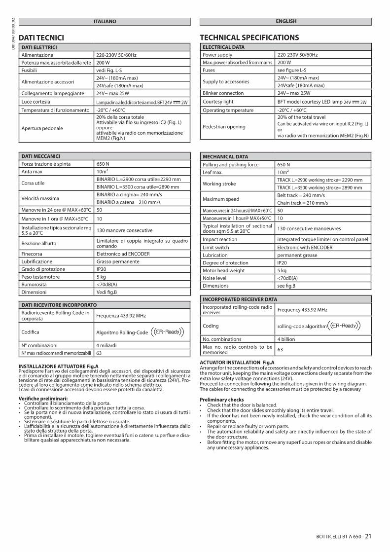
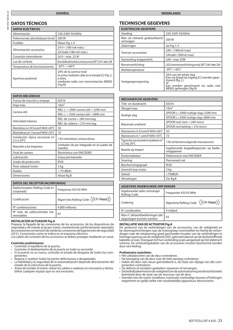
DATI TECNICIDATI ELETTRICIAlimentazione 220-230V 50/60HzPotenza max. assorbita dalla rete 200 WFusibili vedi Fig. L-S
Alimentazione accessori24V~ (180mA max)24Vsafe (180mA max)
Collegamento lampeggiante 24V~ max 25W
Luce cortesia Lampadina a led di cortesia mod. BFT 24V 2WTemperatura di funzionamento -20°C / +60°C
Apertura pedonale
20% della corsa totaleAttivabile via filo su ingresso IC2 (Fig. L)oppure attivabile via radio con memorizzazione MEM2 (Fig.N)
DATI MECCANICIForza trazione e spinta 650 NAnta max 10m2
Corsa utileBINARIO L.=2900 corsa utile=2290 mm BINARIO L.=3500 corsa utile=2890 mm
Velocità massimaBINARIO a cinghia= 240 mm/sBINARIO a catena= 210 mm/s
Manovre in 24 ore @ MAX+60°C 50
Manovre in 1 ora @ MAX+50°C 10
Installazione tipica sezionale mq 5,5 a 20°C 130 manovre consecutive
Reazione all’urto Limitatore di coppia integrato su quadro comando
Finecorsa Elettronico ad ENCODERLubrificazione Grasso permanenteGrado di protezione IP20Peso testamotore 5 kgRumorosità <70dB(A)Dimensioni Vedi fig.B
DATI RICEVITORE INCORPORATORadioricevente Rolling-Code in-corporata Frequenza 433.92 MHz
Codifica Algoritmo Rolling-Code
N° combinazioni 4 miliardiN° max radiocomandi memorizzabili 63
INSTALLAZIONE ATTUATORE Fig.APredisporre l’arrivo dei collegamenti degli accessori, dei dispositivi di sicurezza e di comando al gruppo motore tenendo nettamente separati i collegamenti a tensione di rete dai collegamenti in bassissima tensione di sicurezza (24V). Pro-cedere al loro collegamento come indicato nello schema elettrico.I cavi di connessione accessori devono essere protetti da canaletta.
Verifiche preliminari:• Controllare il bilanciamento della porta.• Controllare lo scorrimento della porta per tutta la corsa.• Se la porta non è di nuova installazione, controllare lo stato di usura di tutti i
componenti.• Sistemare o sostituire le parti difettose o usurate.• L’affidabilità e la sicurezza dell’automazione è direttamente influenzata dallo
stato della struttura della porta.• Prima di installare il motore, togliere eventuali funi o catene superflue e disa-
bilitare qualsiasi apparecchiatura non necessaria.
ITALIANO ENGLISH
TECHNICAL SPECIFICATIONSELECTRICAL DATAPower supply 220-230V 50/60HzMax. power absorbed from mains 200 WFuses see figure L-S
Supply to accessories24V~ (180mA max)24Vsafe (180mA max)
Blinker connection 24V~ max 25W
Courtesy light BFT model courtesy LED lamp 24V 2WOperating temperature -20°C / +60°C
Pedestrian opening
20% of the total travelCan be activated via wire on input IC2 (Fig. L)orvia radio with memorization MEM2 (Fig.N)
MECHANICAL DATAPulling and pushing force 650 NLeaf max. 10m2
Working strokeTRACK L.=2900 working stroke= 2290 mm TRACK L.=3500 working stroke= 2890 mm
Maximum speedBelt track = 240 mm/sChain track = 210 mm/s
Manoeuvres in 24 hours@ MAX+60°C 50Manoeuvres in 1 hour@ MAX+50°C 10Typical installation of sectional doors sqm 5,5 at 20°C 130 consecutive manoeuvres
Impact reaction integrated torque limiter on control panel
Limit switch Electronic with ENCODERLubrication permanent greaseDegree of protection IP20Motor head weight 5 kgNoise level <70dB(A)Dimensions see fig.B
INCORPORATED RECEIVER DATAIncorporated rolling-code radio receiver Frequency 433.92 MHz
Coding rolling-code algorithm
No. combinations 4 billionMax no. radio controls to be memorised 63
ACTUATOR INSTALLATION Fig.AArrange for the connections of accessories and safety and control devices to reach the motor unit, keeping the mains voltage connections clearly separate from the extra low safety voltage connections (24V).Proceed to connection following the indications given in the wiring diagram. The cables for connecting the accessories must be protected by a raceway
Preliminary checks• Check that the door is balanced.• Check that the door slides smoothly along its entire travel.• If the door has not been newly installed, check the wear condition of all its
components.• Repair or replace faulty or worn parts.• The automation reliability and safety are directly influenced by the state of
the door structure.• Before fitting the motor, remove any superfluous ropes or chains and disable
any unnecessary appliances.
BOTTICELLI BT A 650 - 21
D81
3947
001
00_0
2
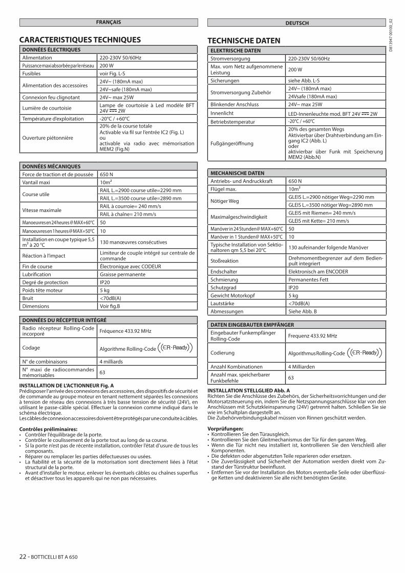
TECHNISCHE DATENELEKTRISCHE DATENStromversorgung 220-230V 50/60HzMax. vom Netz aufgenommene Leistung 200 W
Sicherungen siehe Abb. L-S
Stromversorgung Zubehör24V~ (180mA max)24Vsafe (180mA max)
Blinkender Anschluss 24V~ max 25W
Innenlicht LED-Innenleuchte mod. BFT 24V 2WBetriebstemperatur -20°C / +60°C
Fußgängeröffnung
20% des gesamten WegsAktivierbar über Drahtverbindung am Ein-gang IC2 (Abb. L)oder aktivierbar über Funk mit Speicherung MEM2 (Abb.N)
MECHANISCHE DATENAntriebs- und Andruckkraft 650 NFlügel max. 10m2
Nötiger WegGLEIS L.=2900 nötiger Weg=2290 mm GLEIS L.=3500 nötiger Weg=2890 mm
MaximalgeschwindigkeitGLEIS mit Riemen= 240 mm/sGLEIS mit Kette= 210 mm/s
Manöver in 24 Stunden@ MAX+60°C 50Manöver in 1 Stunden@ MAX+50°C 10Typische Installation von Sektio-naltoren qm 5,5 bei 20°C 130 aufeinander folgende Manöver
Stoßreaktion Drehmomentbegrenzer auf dem Bedien-pult integriert
Endschalter Elektronisch am ENCODERSchmierung Permanentes FettSchutzgrad IP20Gewicht Motorkopf 5 kgLautstärke <70dB(A)Abmessungen Siehe Abb. B
DATEN EINGEBAUTER EMPFÄNGEREingebauter Funkempfänger Rolling-Code Frequenz 433.92 MHz
Codierung Algorithmus Rolling-Code
Anzahl Kombinationen 4 MilliardenAnzahl max. speicherbarer Funkbefehle 63
INSTALLATION STELLGLIED Abb. ARichten Sie die Anschlüsse des Zubehörs, der Sicherheitsvorrichtungen und der Motorsatzsteuerung ein, indem Sie die Netzspannungsanschlüsse klar von den Anschlüssen mit Schutzkleinspannung (24V) getrennt halten. Schließen Sie sie wie im Schaltplan dargestellt an.Die Zubehörverbindungskabel müssen von Rinnen geschützt werden.
Vorprüfungen:• Kontrollieren Sie den Türausgleich.• Kontrollieren Sie den Gleitmechanismus der Tür für den ganzen Weg.• Wenn die Tür nicht neu installiert ist, kontrollieren Sie den Verschleiß aller
Komponenten.• Die defekten oder abgenutzten Teile reparieren oder ersetzen.• Die Zuverlässigkeit und Sicherheit der Automation werden direkt vom Zu-
stand der Türstruktur beeinflusst.• Entfernen Sie vor der Installation des Motors eventuelle Seile oder überflüssi-
ge Ketten und deaktivieren Sie alle nicht benötigten Geräte.
DEUTSCHFRANÇAIS
CARACTERISTIQUES TECHNIQUESDONNÉES ÉLECTRIQUESAlimentation 220-230V 50/60HzPuissance maxi absorbée par le réseau 200 WFusibles voir Fig. L-S
Alimentation des accessoires24V~ (180mA max)24V~safe (180mA max)
Connexion feu clignotant 24V~ max 25W
Lumière de courtoisie Lampe de courtoisie à Led modèle BFT 24V 2W
Température d’exploitation -20°C / +60°C
Ouverture piétonnière
20% de la course totaleActivable via fil sur l’entrée IC2 (Fig. L)ou activable via radio avec mémorisation MEM2 (Fig.N)
DONNÉES MÉCANIQUESForce de traction et de poussée 650 NVantail maxi 10m2
Course utileRAIL L.=2900 course utile=2290 mm RAIL L.=3500 course utile=2890 mm
Vitesse maximaleRAIL à courroie= 240 mm/sRAIL à chaîne= 210 mm/s
Manoeuvres en 24 heures @ MAX+60°C 50
Manoeuvres en 1 heures @ MAX+50°C 10
Installation en coupe typique 5,5 m² à 20 °C 130 manœuvres consécutives
Réaction à l’impact Limiteur de couple intégré sur centrale de commande
Fin de course Électronique avec CODEURLubrification Graisse permanenteDegré de protection IP20Poids tête moteur 5 kgBruit <70dB(A)Dimensions Voir fig.B
DONNÉES DU RÉCEPTEUR INTÉGRÉRadio récepteur Rolling-Code incorporé Fréquence 433.92 MHz
Codage Algorithme Rolling-Code
N° de combinaisons 4 milliardsN° maxi de radiocommandes mémorisables 63
INSTALLATION DE L’ACTIONNEUR Fig. APrédisposer l’arrivée des connexions des accessoires, des dispositifs de sécurité et de commande au groupe moteur en tenant nettement séparées les connexions à tension de réseau des connexions à très basse tension de sécurité (24V), en utilisant le passe-câble spécial. Effectuer la connexion comme indiqué dans le schéma électrique.Les câbles de connexion accessoires doivent être protégés par une conduite à câbles.
Contrôles préliminaires:• Contrôler l’équilibrage de la porte.• Contrôler le coulissement de la porte tout au long de sa course.• Si la porte n’est pas de récente installation, contrôler l’état d’usure de tous les
composants.• Réparer ou remplacer les parties défectueuses ou usées.• La fiabilité et la sécurité de la motorisation sont directement liées à l’état
structural de la porte.• Avant d’installer le moteur, enlever les éventuels câbles ou chaînes superflus
et désactiver tous les appareils qui ne non pas nécessaires.
22 - BOTTICELLI BT A 650
D81
3947
001
00_0
2
DATOS TÉCNICOSDATOS ELÉCTRICOSAlimentación 220-230V 50/60HzPotencia máx. absorbida por la red 200 WFusibles Véase Fig. L-S
Alimentación accesorios24 V~ (180 mA máx.)24 Vsafe (180 mA máx.)
Conexión intermitente 24 V~ máx. 25 W
Luz de cortesía Bombilla de led de cortesía mod. BFT 24 V 2 W
Temperatura de funcionamiento -20°C / +60°C
Apertura peatonal
20% de la carrera totalSe activa mediante cable en la entrada IC2 (Fig. L)o bien, mediante radio con memorización MEM2 (Fig.N)
DATOS MECÁNICOSFuerza de tracción y empuje 650 NHoja máx. 10m2
Carrera útilRIEL L. = 2900 carrera útil = 2290 mm RIEL L. = 3500 carrera útil = 2890 mm
Velocidad máximaRIEL de correa = 240 mm/seg.RIEL de cadena = 210 mm/seg.
Maniobras en 24 horas@ MAX+60°C 50Maniobras en 1 horas@ MAX+50°C 10Instalación típica seccional m2 5,5 a 20°C 130 maniobras consecutivas
Reacción a los impactos Limitador de par integrado en el cuadro de mandos
Final de carrera Electrónico con ENCODERLubricación Grasa permanenteGrado de protección IP20Peso cabezal motor 5 kgRuidos < 70 dB(A)Dimensiones Véase fig.B
DATOS DEL RECEPTOR INCORPORADORadiorreceptor Rolling-Code in-corporado Frequenza 433.92 MHz
Codificación Algori tmo Rolling-Code
N° combinaciones 4.000 millonesN° máx. de radiocontroles me-morizables 63
INSTALACIÓN ACTUADOR Fig.APreparar la llegada de las conexiones de los accesorios, de los dispositivos de seguridad y de mando al grupo motor, manteniendo perfectamente separadas las conexiones con tensión de red de las conexiones de baja tensión de seguridad (24 V). Conectarlas como se indica en el esquema eléctrico.Los cables de conexión de los accesorios se deben proteger mediante un canal.
Controles preliminares:• Controlar el equilibrio de la puerta.• Controlar el deslizamiento de la puerta en todo su recorrido.• Si la puerta no es nueva, controlar el estado de desgaste de todos los com-
ponentes.• Reparar o sustituir todas las partes defectuosas o desgastadas.• La fiabilidad y la seguridad de la automatización depende directamente del
estado de la estructura de la puerta.• Antes de instalar el motor, retirar los cables o cadenas no necesarios y desha-
bilitar cualquier equipo que no sea necesario.
TECHNISCHE GEGEVENSELEKTRISCHE GEGEVENSVoeding 220-230V 50/60HzMax uit netwerk geabsorbeerd vermogen 200 W
Zekeringen zie Fig. L-S
Toevoer accessoires24V~ (180mA max)24Vsafe (180mA max)
Aansluiting knipperlicht 24V~ max 25W
Binnenverlichting LED-binnenverlichting mod. BFT 24V 2W
Werktemperatuur -20°C / +60°C
Voetgangersopening
20% van de totale slagKan via draad op ingang IC2 worden geac-tiveerd (fig. L)of kan worden geactiveerd via radio met MEM2-geheugen (fig.N)
MECHANISCHE GEGEVENSTrek- en duwkracht 650 NVleugel max. 10m2
Nuttige slagSPOOR L.=2900 nuttige slag=2290 mm SPOOR L.=3500 nuttige slag=2890 mm
Maximale snelheidSPOOR met riem = 240 mm/sSPOOR met ketting = 210 mm/s
Manoeuvers in 24 uren@ MAX+60°C 50Manoeuvers in 1 uren@ MAX+50°C 10Typische sectionele installatie m² 5,5 bij 20°C 130 achtereenvolgende manoeuvres
Reactie op impact Ingebouwde koppelbegrenzer op bedie-ningspaneel
Eindschakelaar Elektronisch met ENCODERSmering Permanent vetBeschermingsgraad IP20Gewicht kop motor 5 kgGeluid <70dB(A)Afmetingen Zie fig.B
GEGEVENS INGEBOUWDE ONTVANGERIngebouwde radio-ontvanger Rolling-Code Frequentie 433.92 MHz
Codering Algoritme Rolling-Code
N° combinaties 4 miljardMax n° afstandsbedieningen die opgeslagen kunnen worden 63
INSTALLATIE VAN DE ACTIVATOR Fig.ADe aankomst van de verbindingen van de accessoires, van de veiligheids en be-dieningsinrichtingen naar de motorgroep voorinstellen en hierbij de verbin-dingen naar de netspanning goed gescheiden houden van de verbindingen in heel lage spaning van de veiligheid (24V), gebruikmakend van de desbetreffende kabeldo-orvoer. Overgaan tot hun verbinding zoals aangeduid op het elektrisch schema. De verbindingskabels van de accessoires moeten beschermd worden door een leiding.
Preliminaire nazichten:• Het uitbalanceren van de deur controleren.• De beweging van de deur over de hele aanslag controleren. • Indien de deur niet nieuw geïnstalleerd is, de staat van slijtage van alle com-
ponenten controleren.• De defecte of versleten gedeelten repareren of vervangen. • De bedrijfszekerheid en de veiligheid van de automatisering wordt rechtstreeks
beïnvloed door de staat van de structuur van de deur.• Voordat men de motor installeert, eventuele overbodige touwen of kettingen
wegnemen en gelijk welke niet noodzakelijke apparatuur desactiveren.
ESPAÑOL NEDERLANDS
BOTTICELLI BT A 650 - 23
D81
3947
001
00_0
2
R
S
T
1 2
3
CLICK
PH2
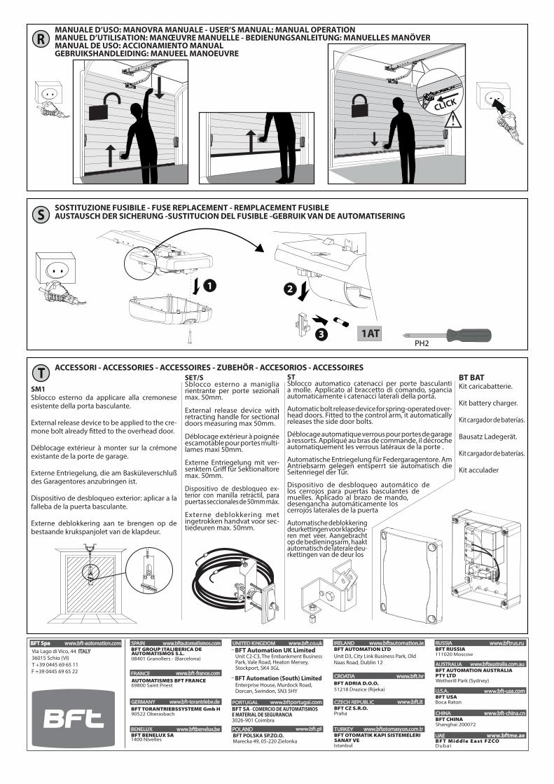
MANUALE D’USO: MANOVRA MANUALE - USER’S MANUAL: MANUAL OPERATION MANUEL D’UTILISATION: MANŒUVRE MANUELLE - BEDIENUNGSANLEITUNG: MANUELLES MANÖVERMANUAL DE USO: ACCIONAMIENTO MANUALGEBRUIKSHANDLEIDING: MANUEEL MANOEUVRE
SOSTITUZIONE FUSIBILE - FUSE REPLACEMENT - REMPLACEMENT FUSIBLEAUSTAUSCH DER SICHERUNG -SUSTITUCION DEL FUSIBLE -GEBRUIK VAN DE AUTOMATISERING
ACCESSORI - ACCESSORIES - ACCESSOIRES - ZUBEHÖR - ACCESORIOS - ACCESSOIRESSTSblocco automatico catenacci per porte basculanti a molle. Applicato al braccetto di comando, sgancia automaticamente i catenacci laterali della porta.
Automatic bolt release device for spring-operated over-head doors. Fitted to the control arm, it automatically releases the side door bolts.
Déblocage automatique verrous pour portes de garage à ressorts. Appliqué au bras de commande, il décroche automatiquement les verrous latéraux de la porte .
Automatische Entriegelung für Federgaragentore. Am Antriebsarm gelegen entsperrt sie automatisch die Seitenriegel der Tür.
Dispositivo de desbloqueo automático de los cerrojos para puertas basculantes de muelles. Aplicado al brazo de mando, desengancha automáticamente los cerrojos laterales de la puerta
Automatische deblokkering deurkettingen voor klapdeu-ren met veer. Aangebracht op de bedieningsarm, haakt automatisch de laterale deu-rkettingen van de deur los
SM1Sblocco esterno da applicare alla cremonese esistente della porta basculante.
External release device to be applied to the cre-mone bolt already fitted to the overhead door.
Déblocage extérieur à monter sur la crémone existante de la porte de garage.
Externe Entriegelung, die am Basküleverschluß des Garagentores anzubringen ist.
Dispositivo de desbloqueo exterior: aplicar a la falleba de la puerta basculante.
Externe deblokkering aan te brengen op de bestaande krukspanjolet van de klapdeur.
BT BAT Kit caricabatterie.
Kit battery charger.
Kit cargador de baterías.
Bausatz Ladegerät.
Kit cargador de baterías.
Kit acculader
SET/SSblocco esterno a maniglia rientrante per porte sezionali max. 50mm.
External release device with retracting handle for sectional doors measuring max 50mm.
Déblocage extérieur à poignée escamotable pour portes multi-lames maxi 50mm.
Externe Entriegelung mit ver-senktem Griff für Sektionaltore max. 50mm.
Dispositivo de desbloqueo ex-terior con manilla retráctil, para puertas seccionales de 50mm máx.
Externe deblokkering met ingetrokken handvat voor sec-tiedeuren max. 50mm.
1AT
www.bftme.ae

![PIANO DI RIDUZIONE DELLE PERDITE IDRICHE SU RETI DI ...lnx.ato4cuneese.it/wp/wp-content/uploads/2019/02/S556-01-00100-r… · 38-41 via Cima 365 De 90 PEAD Lunghezza TOT [m] 4606](https://static.fdocumenti.com/doc/165x107/60180c538f72433133531676/piano-di-riduzione-delle-perdite-idriche-su-reti-di-lnx-38-41-via-cima-365-de.jpg)