AZIENDA CERTIFICATA ISO 9001 - termoplus.ro · N.B.: È necessario osservare scrupolosamente la...
112
MANUALE DI INSTALLAZIONE E MANUTENZIONE INSTALLATION AND MAINTENANCE MANUAL NOTICE D’INSTALLATION ET D’ENTRETIEN INSTALLATIONS- UND WARTUNGSANLEITUNG MANUAL PARA LA INSTALACIÓN Y EL MANTENIMIENTO ECO 30 - ECO 30/2 - ECO 40/2 AZIENDA CERTIFICATA ISO 9001 BRUCIATORE DI GASOLIO LIGHT OIL BURNERS BRULEUR FIOUL DOMESTIQUE ÖLBRENNER QUEMADORES PARA GASÓLEO ∫∞À™∆∏ƒ∞™ ¶∂∆ƒ∂§∞π√À ∂°Ã∂πƒπ¢π√ ∂°∫∞∆∞™∆∞™∏™ ∫∞π ™À¡∆∏ƒ∏™∏™
Transcript of AZIENDA CERTIFICATA ISO 9001 - termoplus.ro · N.B.: È necessario osservare scrupolosamente la...

MANUALE DIINSTALLAZIONE EMANUTENZIONE
INSTALLATION ANDMAINTENANCE
MANUAL
NOTICED’INSTALLATIONET D’ENTRETIEN
INSTALLATIONS-UND
WARTUNGSANLEITUNG
MANUAL PARA LAINSTALACIÓN Y ELMANTENIMIENTO
ECO 30 - ECO 30/2 - ECO 40/2
AZIENDA CERTIFICATA ISO 9001
BRUCIATORE DI GASOLIO
LIGHT OIL BURNERS
BRULEUR FIOUL DOMESTIQUE
ÖLBRENNER
QUEMADORES PARA GASÓLEO
∫∞À™∆∏ƒ∞™ ¶∂∆ƒ∂§∞π√À
∂°Ã∂πƒπ¢π√
∂°∫∞∆∞™∆∞™∏™
∫∞π ™À¡∆∏ƒ∏™∏™


Leggere attentamente le istruzioni ed avvertenze contenute sul presente libretto in quantoforniscono importanti indicazioni riguardanti la sicurezza d’installazione, d’uso e di ma-nutenzione. Conservare con cura questo libretto per ogni ulteriore consultazione.L’installazione deve essere effettuata da personale qualificato che sarà responsabile delrispetto delle norme di sicurezza vigenti.
ITALIANO 4
Please read the instructions and warnings in this document carefully as there is importantinformation regarding installation, use and maintenance. Keep the manual in a safe placefor future reference. The installation must be carried out by qualified personnel that will beresponsible for conformance with current safety regulations in force.
ENGLISH 22
Lire attentivement les instructions et les avertissements contenus dans ce manuel, car ilsproportionnent d’importantes indications concernant la sécurité de montage, d’emploi etd’entretien. Garder avec soin ce manuel pour toute autre consultation. Seulement le personnelqualifié, qui sera responsable du respect des lois de sécurité en vigeur, peut réaliser lemontage.
FRANÇAIS 40
Die in dieser Anleitung enthaltenen Anweisungen und Hinweise lesen, da sie wichtigeAngaben zur Sicherheit, Verwendung und Wartung liefern. Das Handbuch ist zumNachschlagen sorgfältig aufzubewahren. Die Installation muss von qualifiziertem Perso-nal vorgenommen werden, das für die Einhaltung der geltenden Sicherheitsvorschriftenverantwortlich ist.
DEUCHT 58
Leer detenidamente las instrucciones y advertencias contenidas en el presente manual porcuanto ofrecen importantes indicaciones que se refieren a la seguridad de instalación, deuso y de mantenimiento. Tratar este manual con delicadeza y conservarlo en un lugarseguro para poder consultarlo cada vez que sea necesario. La instalación deberá serrealizada p or personal capacitado y calificado, que tendrá asimismo la responsabilidadde respetar la normativa vigente sobre seguridad.
ESPAÑOL 76
¢È·‚¿ÛÙ ÚÔÛÂÎÙÈο ÙȘ Ô‰ËÁ›Â˜ Î·È ÙȘ ÚÔÂȉÔÔÈ‹ÛÂȘ Ô˘ ÂÚȤ¯ÔÓÙ·È ÛÙÔ ·ÚfiÓÂÁ¯ÂÈÚ›‰ÈÔ ·ÊÔ‡ ·Ú¤¯Ô˘Ó ÛËÌ·ÓÙÈΤ˜ ˘Ô‰Â›ÍÂȘ Û¯ÂÙÈΤ˜ Ì ÙËÓ ·ÛÊ¿ÏÂÈ·ÂÁηٿÛÙ·Û˘, ¯Ú‹Û˘ Î·È Û˘ÓÙ‹ÚËÛ˘. º˘Ï¿ÍÙ ÚÔÛÂÎÙÈο ÙÔ ÂÁ¯ÂÈÚ›‰ÈÔ, ÒÛÙÂÓ· ÌÔÚ›Ù ӷ ·Ó·ÙÚ¤ÍÂÙ Û ·˘Ùfi ÛÙÔ Ì¤ÏÏÔÓ.∏ ÂÁηٿÛÙ·ÛË Ú¤ÂÈ Ó· ‰ÈÂÓÂÚÁËı› ·fi ÂȉÈÎÂ˘Ì¤ÓÔ ÚÔÛˆÈÎfi Ô˘ ı· Â›Ó·È˘Â‡ı˘ÓÔ ÁÈ· ÙËÓ Ù‹ÚËÛË ÙˆÓ ÈÛ¯˘fiÓÙˆÓ Î·ÓÔÓÈÛÌÒÓ ·ÛÊ·Ï›·˜.
∂§§∏¡π∫∞ 94
4
Complimenti......Per l'ottima scelta. La ringraziamo per la preferenza accordata ai ns. prodotti.
LAMBORGHINI CALORECLIMA è da 1959 attivamente presente in Italia e nel mondo conuna rete capillare di Agenti e concessionari, che garantiscono costantemente la presenza delprodotto sul mercato. Si affianca a questo un servizio di assistenza tecnica, «LAMBORGHINISERVICE», al quale è affidata una qualificata manutenzione del prodotto.
INDICE PAGINA
CARATTERISTICHE TECNICHE _______________________ 5DIMENSIONI _____________________________________ 5CURVE DI LAVORO ________________________________ 6MONTAGGIO ALLA CALDAIA ______________________ 6COLLEGAMENTI ELETTRICI _________________________ 7ALIMENTAZIONE GASOLIO ________________________ 9ALIMENTAZIONE MONOTUBO _____________________ 9ALIMENTAZIONE BITUBO __________________________ 9SCELTA UGELLO _________________________________ 10ESEMPIO SCELTA UGELLO _________________________ 10MONTAGGIO UGELLO ___________________________ 10POSIZIONAMENTO ELETTRODI-DEFLETTORE _________ 11CICLO FUNZIONAMENTO ________________________ 11APPARECCHIATURA LMO _________________________ 14REGOLAZIONE TESTA ____________________________ 15REGOLAZIONE ARIA DI COMBUSTIONE (ECO 30) ____ 15REGOLAZIONE ARIA DI COMBUSTIONE (ECO 30/2 - ECO 40/2) __ 15MESSA IN FUNZIONE ____________________________ 16REGOLAZIONE PRESSIONE POMPA ________________ 17CONTROLLO COMBUSTIONE______________________ 17MANUTENZIONE ________________________________ 18FOTO RESISTENZA _______________________________ 18FILTRO POMPA __________________________________ 18FILTRO DI LINEA _________________________________ 18VENTOLA SERRANDA ARIA _______________________ 18ELETTRODI UGELLO ______________________________ 19IRREGOLARITA’ DI FUNZIONAMENTO ______________ 20
Per l’installazione e per il posizionamento del bruciatore:RISPETTARE SCRUPOLOSAMENTE LE NORME LOCALI VIGENTI

5
CARATTERISTICHE TECNICHE
N.B.: I dati riportati fra parentesi si riferiscono alla minima portata ottenibile con la 1a fiamma.
DIMENSIONI mm
X
F H
L
M8
N
A B
C
ED
H Nø G
min maxModello A B C D E F Ø G H L N X
ECO 30 770 420 423 460 310 350 135 120 160 150 200 3/8”ECO 30/2 770 420 423 460 330 350 135 120 160 150 200 3/8”ECO 40/2 790 420 423 460 330 350 148 120 160 160 200 3/8”
MODELLO ECO 30 ECO 30/2 ECO 40/2Potenza termica min. kW 190 142 267
max. kW 356 356 474min. kcal/h 163.000 122.400 230.000max. kcal/h 306.000 306.000 408.000
Consumo combustibile min. Kg/h 16 (12) - 14 (22,5) - 25max. Kg/h 30 30 40
Pressione di Taraturapompa combustibile bar 12 12 12
Combustibile gasolio p.c.i. 10210 Kcal/Kg 1,5°E (6cst) a 20°CPeso kg 26,5 27 28Motore W 370 370 370Condensatore 450 V µF 14 14 14Trasformatore di accensione kV/mA 12/35 12/35 12/35Alimentazione elettrica 230V - 50 Hz monofasePotenza totale assorbita W 850 900 950Apparecchiatura di controllo fiamma Termica c/fotores. Elettronica c/fotores.Regolazione aria Manuale Motorizzata MotorizzataNumero stadi 1 2 2

6
CURVE DI LAVORO
Indicano la potenza in kW, in funzione della contropressione, in mbar, in camera di combustione.
ECO 30
100 130 160 190 220 250 280 310 340 370 400 430 460 490 520 550POTENZA kW
6
4
3
2
1
0PRES
SIO
NE
IN C
AM
ERA
DI C
OM
BUST
ION
E m
bar
ECO 40/2
5
ECO 30/2
MONTAGGIO ALLA CALDAIA
Fissare la flangia 2 alla caldaia con n° 4 viti 3 interponendo la guarnizione isolante 4 e l’eventuale cordaisolante 5. Infilare il bruciatore nella flangia in modo che il boccaglio penetri nella camera di combustionesecondo le indicazioni del costruttore della caldaia. Stringere la vite 1 per bloccare il bruciatore.
1 4
3 2 5

7
COLLEGAMENTI ELETTRICI
I collegamenti da effettuare a cura dell’installatore sono:● linea di alimentazione● linea termostatica● eventuale lampada di blocco● eventuale contaore● eventuale termostato modulazione fiamma
(togliere il cavo che ponticella)
N.B.: È necessario osservare scrupolosamente la buona norma che indica il collegamento di massimo duecavi per morsetto.
Attenzione:● non scambiare il neutro con la fase● eseguire un buon collegamento di terra● rispettare le norme della buona tecnica ed osservare scrupolosamente le norme locali vigenti
ECO 30
MPELOA 24.../LMO14...
LEGENDA
F FusibileFA Filtro antidisturboFCA Fusibile circuito ausiliarioFR FotoresistenzaIG Interruttore generaleIMA Interruttore marcia-arresto
MB Motore bruciatoreMPE Morset. Apparec. LandisTC Termostato caldaiaTS Termostato di sicurezzaTR Trasformatore di accensioneVE Valvola Elettromagnetica

8
I collegamenti da effettuare a cura dell’installatore sono:● linea di alimentazione● linea termostatica● eventuale lampada di blocco● eventuale contaore● eventuale termostato modulazione fiamma (togliere il cavo che ponticella)
N.B.: È necessario osservare scrupolosamente la buona norma che indica il collegamento di massimo duecavi per morsetto.
Attenzione:● non scambiare il neutro con la fase● eseguire un buon collegamento di terra● rispettare le norme della buona tecnica ed osservare scrupolosamente le norme locali vigenti
ECO 30/2 - ECO 40/2
1 2 2 3 4 5 6 7 8 10 11 129
M
MB
VE1
TC
TS F IG
B4
T2T1N
L1
S3
L
N
FR
2
IMA
3 5 6 1 8 N4 7 MMS
VE2
TR
FA
FCA
2 3 4 5 6 71 8 9
2N
ImM
TMF
31
L1
LEGENDA
F FusibileFA Filtro antidisturboFCA Fusibile circuito ausiliarioFR FotoresistenzaIG Interruttore generaleIma Interruttore marcia-arrestoImM Interruttore funzionamento min.- max.MB Motore bruciatore
MMS Morset. motorino servocomando ariaMPE Morset. Apparec. LandisTC Termostato caldaiaTMF Termostato modulazione 2° fiamma (event.)TS Termostato di sicurezzaTR Trasformatore di accensioneVE1 Valvola Elettromagnetica 1° fiammaVE2 Valvola Elettromagnetica 2° fiamma
MPELOA 24.../LMO24...(ECO 30/2)LOA 44.../LMO44...(ECO 40/2)

9
ALIMENTAZIONE GASOLIO
Le dimensioni delle tubazioni (diametro/lunghezza) sono in relazione con il tipo di impianto (a uno/due tubi,in aspirazione/caduta) e con le caratteristiche della pompa.Il diagramma, indica la massima lunghezza L consentita di una linea di aspirazione in funzione del dislivelloH e del diametro interno del tubo d, per una pressione atmosferica di 1013 mbar ed un vuoto di 0,45 bar econsiderando il montaggio di 4 gomiti, di una valvola di blocco ed una di non ritorno.
ALIMENTAZIONE MONOTUBO
Si raccomanda di evitare, per quanto possibile, questa soluzione poichè è noto che essa può originare note-voli disfunzioni al bruciatore se non è realizzata in modo perfetto. Se, tuttavia, non è possibile evitare questainstallazione, si tenga presente: eseguire solo impianti a caduta; modificare la pompa togliendo il granointerno; prevedere idonei spurghi dell’aria nei punti più alti della tubazione ed evitare il formarsi di sacched’aria.
ALIMENTAZIONE BITUBO
N. B.: Se la lunghezza della tubazione supera 60m, si consiglia una pompa di alimentazione- d10 (2), d12 (2): per bruciatori a due fiamme.
10
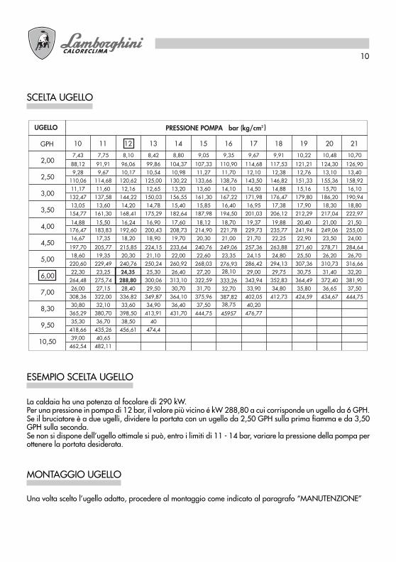
SCELTA UGELLO
PRESSIONE POMPA bar (kg/cm2 )UGELLO
GPH
2,00
2,50
3,00
3,50
4,00
4,50
5,00
6,00
7,00
8,30
9,50
10,50
10 11 12 13 14 15 16 17 18 19 20 21
7,43 7,75 8,10 8,42 8,80 9,05 9,35 9,67 9,91 10,22 10,48 10,70
88,12 91,91 96,06 99,86 104,37 107,33 110,90 114,68 117,53 121,21 124,30 126,909,28 9,67 10,17 10,54 10,98 11,27 11,70 12,10 12,38 12,76 13,10 13,40
110,06 114,68 120,62 125,00 130,22 133,66 138,76 143,50 146,82 151,33 155,36 158,9211,17 11,60 12,16 12,65 13,20 13,60 14,10 14,50 14,88 15,16 15,70 16,10
132,47 137,58 144,22 150,03 156,55 161,30 167,22 171,98 176,47 179,80 186,20 190,9413,05 13,60 14,20 14,78 15,40 15,85 16,40 16,95 17,38 17,90 18,30 18,80
154,77 161,30 168,41 175,29 182,64 187,98 194,50 201,03 206,12 212,29 217,04 222,97
14,88 15,50 16,24 16,90 17,60 18,12 18,70 19,37 19,88 20,40 21,00 21,50176,47 183,83 192,60 200,43 208,73 214,90 221,78 229,73 235,77 241,94 249,06 255,0016,67 17,35 18,20 18,90 19,70 20,30 21,00 21,70 22,25 22,90 23,50 24,00
197,70 205,77 215,85 224,15 233,64 240,76 249,06 257,36 263,88 271,60 278,71 284,6418,60 19,35 20,30 21,10 22,00 22,60 23,35 24,15 24,80 25,50 26,20 26,70
220,60 229,49 240,76 250,24 260,92 268,03 286,42 294,13 307,36 310,73 316,6622,30 23,25 24,35 25,30 26,40 27,20
276,9329,00 29,75 30,75 31,40 32,20
264,48 275,74 288,80 300,06 313,10 322,59
28,10
343,94 352,83 364,49 372,40 381,9026,00 27,15 28,40 29,50 30,70 31,70
333,2633,90 34,80 35,80 36,65 37,50
308,36 322,00 336,82 349,87 364,10 375,9632,70
402,05 412,73 424,59 434,67 444,7530,80 32,10 33,60 34,90 36,40 37,50
387,8240,20
365,29 380,70 398,50 413,91 431,70 444,75
38,75
476,7735,30 36,70 38,50 40
45957
418,66 435,26 456,61 474,439,00 40,65
462,54 482,11
ESEMPIO SCELTA UGELLO
MONTAGGIO UGELLO
La caldaia ha una potenza al focolare di 290 kW.Per una pressione in pompa di 12 bar, il valore più vicino é kW 288,80 a cui corrisponde un ugello da 6 GPH.Se il bruciatore è a due ugelli, dividere la portata con un ugello da 2,50 GPH sulla prima fiamma e da 3,50GPH sulla seconda.Se non si dispone dell’ugello ottimale si può, entro i limiti di 11 - 14 bar, variare la pressione della pompa perottenere la portata desiderata.
Una volta scelto l’ugello adatto, procedere al montaggio come indicato al paragrafo “MANUTENZIONE”
11
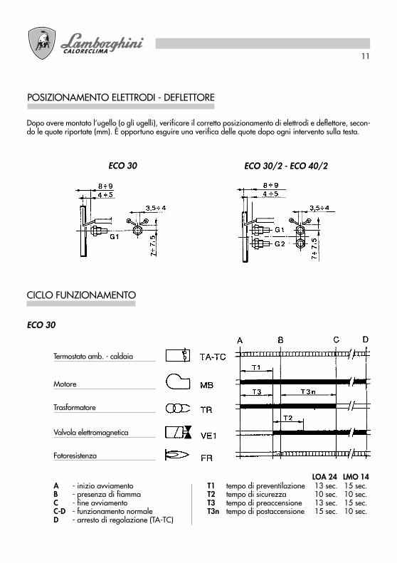
POSIZIONAMENTO ELETTRODI - DEFLETTORE
Dopo avere montato l’ugello (o gli ugelli), verificare il corretto posizionamento di elettrodi e deflettore, secon-do le quote riportate (mm). È opportuno esguire una verifica delle quote dopo ogni intervento sulla testa.
ECO 30 ECO 30/2 - ECO 40/2
CICLO FUNZIONAMENTO
A - inizio avviamentoB - presenza di fiammaC - fine avviamentoC-D - funzionamento normaleD - arresto di regolazione (TA-TC)
T1 tempo di preventilazione 13 sec. 15 sec.T2 tempo di sicurezza 10 sec. 10 sec.T3 tempo di preaccensione 13 sec. 15 sec.T3n tempo di postaccensione 15 sec. 10 sec.
ECO 30
Termostato amb. - caldaia
Motore
Trasformatore
Valvola elettromagnetica
Fotoresistenza
LOA 24 LMO 14

12
A - inizio avviamentoB - presenza di fiammaC - fine avviamentoC-D - funzionamento normaleD - arresto di regolazione (TA-TC)
T1 tempo di preventilazione 13 sec. 15 sec.T2 tempo di sicurezza 10 sec. 10 sec.T3 tempo di preaccensione 13 sec. 15 sec.T3n tempo di postaccensione 15 sec. 10 sec.
ECO 30/2
Termostato amb. - caldaia
Motore
Trasformatore
Valvola elettromagnetica 1a fiamma
Fotoresistenza
Termostato modulazione
Servocomando aria
Valvola elettromagnetica 2a fiamma
LOA 24 LMO 24

13
A - inizio avviamentoB - presenza di fiammaC - fine avviamentoC-D - funzionamento normaleD - arresto di regolazione (TA-TC)
ECO 40/2
Termostato amb. - caldaia
Motore
Trasformatore
Valvola elettromagnetica 1a fiamma
Fotoresistenza
Termostato modulazione
Servocomando aria
Valvola elettromagnetica 2a fiamma
LOA 44 LMO 44T1 tempo di preventilazione 25 sec. 26 sec.T2 tempo di sicurezza 5 sec. 5 sec.T3 tempo di preaccensione 25 sec. 25 sec.T3n tempo di postaccensione 2 sec. 5 sec.
14
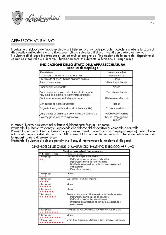
APPARECCHIATURA LMO
Il pulsante di sblocco dell’apparecchiatura è l’elemento principale per poter accedere a tutte le funzioni didiagnostica (attivazione e disattivazione), oltre a sbloccare il dispositivo di comando e controllo.Il pulsante di sblocco è corredato di un led multicolore che da l’indicazione dello stato del dispositivo dicomando e controllo sia durante il funzionamento che durante la funzione di diagnostica.
INDICAZIONI DELLO STATO DELL’APPARECCHIATURATabella di riepilogo
Condizione Sequenza colori
Condizioni di attesa, altri stati intermedi Nessuna luce
Preriscaldo olio “on”, tempo di attesa 5s.max Giallo
Fase di accensione Giallo intermittente
Funzionamento corretto Verde
Funzionamento non corretto, intesità di correnterilevatore fiamma inferiori al minimo ammesso
Verde intermi ttente
Diminuzione tensione di alimentazione Giallo rosso alternati
Condizione di blocco bruciatore Rosso
Segnalazione guasto vedere «tabella a pag.8») Rosso intermittente
Luce parassita prima dell’ accensione del bruciatore Verde rosso alternati
Lampeggìo veloce per diagnostica Rosso lampeggianterapido
In caso di blocco bruciatore nel pulsante di blocco sarà fissa la luce rossa.Premendo il pulsante trasparente si procede allo sblocco del dispositivo di comando e controllo.Premendo per più di 3 sec. la fase di diagnosi verrà attivata (luce rossa con lampeggio rapido), nella tabellasottostante viene riportato il significato della causa di blocco o malfunzionamento in funzione del numero dilampeggi (sempre di colore rosso).Premendo il pulsante di sblocco per almeno 3 sec. si interromperà la funzione di diagnosi.
DIAGNOSI DELLE CAUSE DI MALFUNZIONAMENTO E BLOCCO APP. LMORiepilogo anomalie di funzionamento
Indicazione ottica Possibile cause
2 lampeggi � �
Assenza del segnale di fiamma- Malfunzionamento valvole combustibile- Malfunzionamento rilevatore fiamma- Difettosità nella taratura del bruciatore , assenza di
combustibile- Mancata accensione
3 lampeggi � � �
Libero
4 lampeggi � � � �
Luce estranea all’ accensione
5 lampeggi � � � � �
Libero
6 lampeggi � � � � � �
Libero
7 lampeggi � � � � � � �
Assenza del segnale di fiamma durante funzionamento- Malfunzionamento valvole combustibile- Malfunzionamento rilevatore fiamma- Difettosità nella taratura del bruciatore , assenza di
combustibile
8 lampeggi � � � � � � � �
Anomalia del tempo preriscaldamento del combustibile
9 lampeggi � � � � � � � � �
Libero
10 lampeggi � � � � � � � � � �
Errori di collegamento elettrico o danni all’apparecchiatura
15
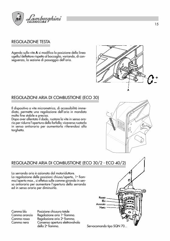
REGOLAZIONI ARIA DI COMBUSTIONE (ECO 30)
Il dispositivo a vite micrometrica, di accessibilità imme-diata, permette una regolazione dell’aria in mandatamolto fine stabile e precisa.Dopo aver allentato il dado, ruotare la vite in senso ora-rio per ridurre l’apertura della farfalla; viceversa ruotarlain senso antiorario per aumentarla riferendosi allatarghetta.
REGOLAZIONE TESTA
Agendo sulla vite A si modifica la posizione della lineaugello/deflettore rispetto al boccaglio, variando, di con-seguenza, la sezione di passaggio dell’aria.
La serranda aria è azionata dal motoriduttore.La regolazione delle posizioni chiuso/aperto, 1a fiam-ma/aperto max., si effetua sulle camme girando in sen-so antiorario per aumentare l’apertura della serrandaed in senso orario per diminuirla.
REGOLAZIONI ARIA DI COMBUSTIONE (ECO 30/2 - ECO 40/2)
Camma blu Posizione chiusura totaleCamma arancio Regolazione aria 1a fiamma.Camma rossa Regolazione aria 2a fiamma.Camma nera Consenso apertura elettrovalvola
della 2a fiamma. Servocomando tipo SQN 70...
16
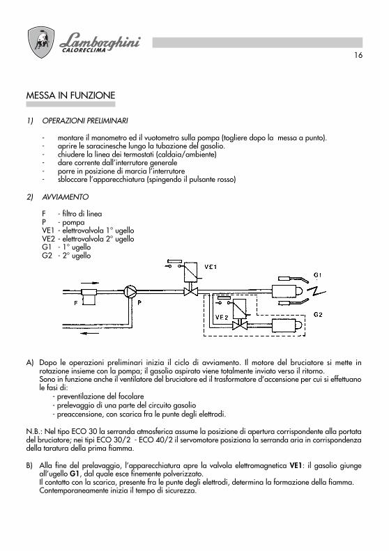
MESSA IN FUNZIONE
1) OPERAZIONI PRELIMINARI
- montare il manometro ed il vuotometro sulla pompa (togliere dopo la messa a punto).- aprire le saracinesche lungo la tubazione del gasolio.- chiudere la linea dei termostati (caldaia/ambiente)- dare corrente dall’interrutore generale- porre in posizione di marcia l’interrutore- sbloccare l’apparecchiatura (spingendo il pulsante rosso)
2) AVVIAMENTO
F - filtro di lineaP - pompaVE1 - elettrovalvola 1° ugelloVE2 - elettrovalvola 2° ugelloG1 - 1° ugelloG2 - 2° ugello
A) Dopo le operazioni preliminari inizia il ciclo di avviamento. Il motore del bruciatore si mette inrotazione insieme con la pompa; il gasolio aspirato viene totalmente inviato verso il ritorno.Sono in funzione anche il ventilatore del bruciatore ed il trasformatore d’accensione per cui si effettuanole fasi di:
- preventilazione del focolare- prelevaggio di una parte del circuito gasolio- preaccensione, con scarica fra le punte degli elettrodi.
N.B.: Nel tipo ECO 30 la serranda atmosferica assume la posizione di apertura corrispondente alla portatadel bruciatore; nei tipi ECO 30/2 - ECO 40/2 il servomotore posiziona la serranda aria in corrispondenzadella taratura della prima fiamma.
B) Alla fine del prelavaggio, l’apparecchiatura apre la valvola elettromagnetica VE1: il gasolio giungeall’ugello G1, dal quale esce finemente polverizzato.Il contatto con la scarica, presente fra le punte degli elettrodi, determina la formazione della fiamma.Contemporaneamente inizia il tempo di sicurezza.

17
La pompa è pretarata a 12 bar.Per il controllo della pressione servirsi di un manometro a bagno d’olio.La pressione può essere normalmente regolata fra 11 e 15 bar.
REGOLAZIONE PRESSIONE POMPA
1 - Aspirazione2 - Ritorno3 - Ugello4 - Regolazione pressione
N.B. Se il vuoto supera 4 m. prevedere una pompa di circolazione
Al fine di ottenere i migliori rendimenti di combustione, e nel rispetto dell’ambiente, si raccomanda di effet-tuare con gli adeguati strumenti, controllo e regolazione della combustione. Valori fondamentali da conside-rare sono:- CO2 Indica con quale eccesso d’aria si svolge la combustione; se si aumenta l’aria, il valore di CO2 %
diminuisce, e se si diminuisce l’aria di combustione il CO2 % aumenta. Valori accettabili sono 11-12 %.
- Numero di fumo (Bacharach). Sta ad indicare che nei fumi sono presenti particelle di incombusto solido.Se si supera il n°2 della scala BH occorre verificare che l’ugello non sia difettoso e che sia adatto albruciatore ed alla caldaia ( marca, tipo, angolo di polverizzazione). In genere il n° BH tende a diminuirealzando la pressione in pompa; é necessario, in questo caso fare attenzione alla portata delcombustibile che aumenta, e quindi, eventualmente, ridurre la capacità dell’ ugello.
- Temperatura dei fumi. È un valore che rappresenta la dispersione di calore attraverso il camino; più altaé la temperatura, maggiori sono le dispersioni e più basso é il rendimento di combustione.
ECO 30/2 - ECO 40/2. Con i bruciatori funzionanti ad alta/bassa fiamma, é necessario accertarsi che nonsi creino le condizioni per la condensazione dei fumi, in caldaia ed al camino. La condensa, essendo di tipoacido, potrebbe provocare gravi corrosioni alla caldaia, pertanto é necessario consultare il costruttore dellamedesima a riguardo. Per quanto concerne il camino, a seconda del materiale con cui é costruito, si possonocreare fenomeni di corrosione, macchie scure di umidità e difficoltà nello smaltimento dei fumi (insufficientetiraggio).
N.B.: Disposizioni vigenti in alcuni paesi possono richiedere regolazioni diverse da quelle riportate erichiedere anche il rispetto di altri parametri. I bruciatori sono progettati per rispettare le più rigidenormative internazionali per il risparmio dell’energia e la tutela dell’ambiente
CONTROLLO COMBUSTIONE
18
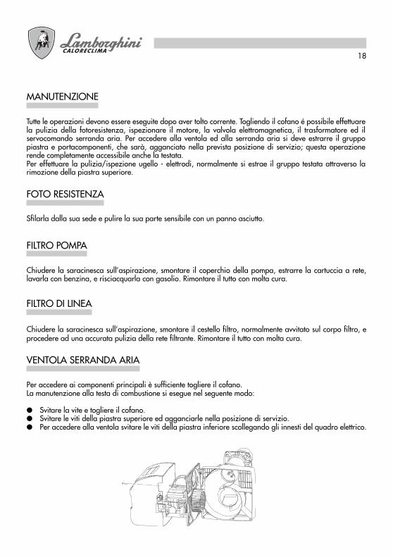
Tutte le operazioni devono essere eseguite dopo aver tolto corrente. Togliendo il cofano é possibile effettuarela pulizia della fotoresistenza, ispezionare il motore, la valvola elettromagnetica, il trasformatore ed ilservocomando serranda aria. Per accedere alla ventola ed alla serranda aria si deve estrarre il gruppopiastra e portacomponenti, che sarà, agganciato nella prevista posizione di servizio; questa operazionerende completamente accessibile anche la testata.Per effettuare la pulizia/ispezione ugello - elettrodi, normalmente si estrae il gruppo testata attraverso larimozione della piastra superiore.
MANUTENZIONE
Sfilarla dalla sua sede e pulire la sua parte sensibile con un panno asciutto.
FOTO RESISTENZA
Chiudere la saracinesca sull’aspirazione, smontare il coperchio della pompa, estrarre la cartuccia a rete,lavarla con benzina, e risciacquarla con gasolio. Rimontare il tutto con molta cura.
FILTRO POMPA
Chiudere la saracinesca sull’aspirazione, smontare il cestello filtro, normalmente avvitato sul corpo filtro, eprocedere ad una accurata pulizia della rete filtrante. Rimontare il tutto con molta cura.
FILTRO DI LINEA
Per accedere ai componenti principali è sufficiente togliere il cofano.La manutenzione alla testa di combustione si esegue nel seguente modo:
● Svitare la vite e togliere il cofano.● Svitare le viti della piastra superiore ed agganciarle nella posizione di servizio.● Per accedere alla ventola svitare le viti della piastra inferiore scollegando gli innesti del quadro elettrico.
VENTOLA SERRANDA ARIA
19
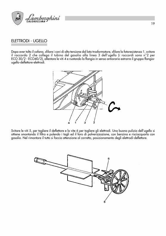
Dopo aver tolto il cofano, sfilare i cavi di alta tensione dal lato trasformatore, sfilare la fotoresistenza 1, svitareil raccordo 2 che collega il tubino del gasolio alla linea 3 dell’ugello (i raccordi sono n°2 perECO 30/2 - ECO40/2), allentare le viti 4 e ruotando la flangia in senso antiorario estrarre il gruppo flangia-ugello-deflettore-elettrodi.
Svitare le viti 5, per togliere il deflettore e la vite 6 per togliere gli elettrodi. Una buona pulizia dell’ugello siottiene smontando il filtro e pulendo i tagli ed il foro di polverizzazione, con benzina e risciacquarlo congasolio. Nel rimontare il tutto si faccia attenzione al corretto, posizionamento degli elettrodi-deflettore.
ELETTRODI - UGELLO
20
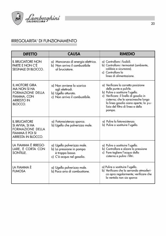
IRREGOLARITA' DI FUNZIONAMENTO
RIMEDIOCAUSADIFETTO
a) Controllare i fusibili.b) Controllare i termostati (ambiente,
caldaia e sicurezza).c) Controllare la
linea di alimentazione.
IL BRUCIATORE NONPARTE E NON C’ÈSEGNALE DI BLOCCO.
a) Verificare la corretta posizionedelle punte e pulirle.
b) Pulire o sostituire l’ugello.c) Verificare: il livello di gasolio in
cisterna; che le saracinesche lungola linea gasolio siano aperte; la p u -lizia del filtro di linea e dellapompa.
IL MOTORE GIRAMA NON SI HAFORMAZIONE DELLAFIAMMA, CONARRESTO INBLOCCO.
a) Pulire la fotoresistenza.b) Pulire o sostituire l’ugello.
IL BRUCIATORESI AVVIA, SI HAFORMAZIONE DELLAFIAMMA E POI SIARRESTA IN BLOCCO.
a) Mancanza di energia elettrica.b) Non arriva il combustibile
al bruciatore.
a) Non avviene la scaricaagli elettrodi.
b) Ugello otturato.c) Non arriva il combustibile.
a) Fotoresistenza sporca.b) Ugello che polverizza male.
LA FIAMMA È IRREGO-LARE, È CORTA CONSCINTILLE.
LA FIAMMA ÈFUMOSA
a) Ugello polverizza male.b) La pressione in pompa
è troppo bassa.c) C’è acqua nel gasolio.
a) Ugello polverizza male.b) Poca aria di combustione.
a) Pulire o sostituire l’ugello.b) Controllare e alzare la pressionec) Fare togliere l’acqua dalla
cisterna e pulire i filtri.
a) Pulire o sostituire l’ugello.b) Verificare che la serranda atmosferi-
ca apra regolarmente; verificare chela ventola non sia sporca

Please read the instructions and warnings in this document carefully as there is importantinformation regarding installation, use and maintenance. Keep the manual in a safe placefor future reference. The installation must be carried out by qualified personnel that will beresponsible for conformance with current safety regulations in force.
GB

22
Congratulations…for an excellent choice. We thank you for choosing our products. Since 1959, LAMBORGHINI
CALORECLIMA has been actively present in Italy and the world with an extensive network of agents anddealers, which guarantees the constant presence of our products on the market.This network is supported by the technical assistance service <<LAMBORGHINI SERVICE>> with theresponsibility of qualified maintenance of the product.
INDEX PAGE
TECHNICAL SPECIFICATIONS ______________________ 23DIMENSIONS ___________________________________ 23PRESSURE CURVE ________________________________ 24ASSEMBLY WITH THE FURNACE____________________ 24ELECTRICAL CONNECTIONS ______________________ 25LIGHT OIL SUPPLY ________________________________ 27SINGLE-LINE FUEL SUPPLY _________________________ 27DOUBLE-LINE FUEL SUPPLY ________________________ 27CHOKE SELECTION ______________________________ 28EXAMPLE OF CHOKE SELECTION __________________ 28MOUNTING THE CHOKE _________________________ 28ELECTRODE-DEFLECTOR POSITIONING _____________ 29OPERATION CYCLE ______________________________ 29LMO EQUIPMENT ________________________________ 32COMBUSTION HEAD ADJUSTMENT ________________ 33AIR INTAKE ADJUSTMENT (ECO 30) ________________ 33AIR INTAKE ADJUSTMENT (ECO 30/2 – ECO 40/2)___ 33STARTING PROCEDURES __________________________ 34PUMP PRESSURE ADJUSTMENT ____________________ 35COMBUSTION CONTROL _________________________ 35MAINTENANCE _________________________________ 36PHOTO RESISTANCE _____________________________ 36PUMP FILTER_____________________________________ 36FUEL LINE FILTER _________________________________ 36FAN & BUTTERFLY VALVE __________________________ 36CHOKE ELECTRODES _____________________________ 37TROUBLE SHOOTING _____________________________ 38
For installation and for positioning the furnace,SCRUPULOUSLY RESPECT THE LOCAL REGULATIONS IN FORCE
23
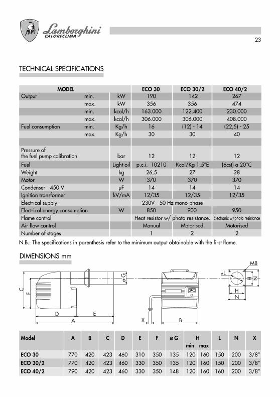
TECHNICAL SPECIFICATIONS
N.B.: The specifications in parenthesis refer to the minimum output obtainable with the first flame.
DIMENSIONS mm
X
F H
L
M8
N
A B
C
ED
H Nø G
min maxModel A B C D E F Ø G H L N X
ECO 30 770 420 423 460 310 350 135 120 160 150 200 3/8”ECO 30/2 770 420 423 460 330 350 135 120 160 150 200 3/8”ECO 40/2 790 420 423 460 330 350 148 120 160 160 200 3/8”
MODEL ECO 30 ECO 30/2 ECO 40/2Output min. kW 190 142 267
max. kW 356 356 474min. kcal/h 163.000 122.400 230.000max. kcal/h 306.000 306.000 408.000
Fuel consumption min. Kg/h 16 (12) - 14 (22,5) - 25max. Kg/h 30 30 40
Pressure ofthe fuel pump calibration bar 12 12 12
Fuel Light oil p.c.i. 10210 Kcal/Kg 1,5°E (6cst) a 20°CWeight kg 26,5 27 28Motor W 370 370 370Condenser 450 V µF 14 14 14Ignition transformer kV/mA 12/35 12/35 12/35Electrical supply 230V - 50 Hz mono-phaseElectrical energy consumption W 850 900 950Flame control Heat resistor w/ photo resistance. Electronic w/photo resistanceAir flow control Manual Motorised MotorisedNumber of stages 1 2 2

24
ECO 30
100 130 160 190 220 250 280 310 340 370 400 430 460 490 520 550POTENZA kW
6
4
3
2
1
0PRES
SIO
NE
IN C
AM
ERA
DI C
OM
BUST
ION
E m
bar
ECO 40/2
5
ECO 30/2
PRESSURE CURVE
Indicates power in kW, in function of back pressure, in mbar, in the combustion chamber
ASSEMBLY WITH THE FURNACE
Attach the flange 2 to the furnace with n° 4 screws (3) through the sealing gasket (4) and any seals (5). Insertthe burner in the flange so that the nozzle enters the combustion chamber as indicated by the manufacturer ofthe furnace. Tighten the screw (1) to lock the burner in place.
1 4
3 2 5
POWER kW
Com
bust
ion
cham
ber
pres
sure
mba
r
25
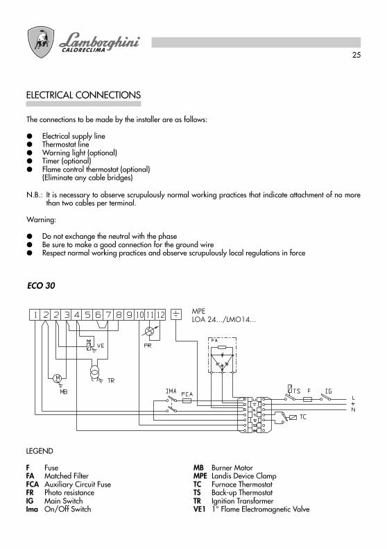
ELECTRICAL CONNECTIONS
The connections to be made by the installer are as follows:
● Electrical supply line● Thermostat line● Warning light (optional)● Timer (optional)● Flame control thermostat (optional)
(Eliminate any cable bridges)
N.B.: It is necessary to observe scrupulously normal working practices that indicate attachment of no morethan two cables per terminal.
Warning:
● Do not exchange the neutral with the phase● Be sure to make a good connection for the ground wire● Respect normal working practices and observe scrupulously local regulations in force
ECO 30
MPELOA 24.../LMO14...
LEGEND
F Fuse MB Burner MotorFA Matched Filter MPE Landis Device ClampFCA Auxiliary Circuit Fuse TC Furnace ThermostatFR Photo resistance TS Back-up ThermostatIG Main Switch TR Ignition TransformerIma On/Off Switch VE1 1° Flame Electromagnetic Valve

26
The installer will make the following connections:
● Energy supply● Thermostatic line● Warning light (optional)● Timer (optional)● Flame control thermostat (optional)
(Eliminate any cable bridges)
N.B.: It is necessary to observe scrupulously normal working practices that indicate attachment of no morethan two cables per terminal.
Warning:
● Do not exchange neutral with phase● Be sure to make a good connection for the ground wire● Respect good working practices and observe scrupulously local regulations in force
ECO 30/2 - ECO 40/2
1 2 2 3 4 5 6 7 8 10 11 129
M
MB
VE1
TC
TS F IG
B4
T2T1N
L1
S3
L
N
FR
2
IMA
3 5 6 1 8 N4 7 MMS
VE2
TR
FA
FCA
2 3 4 5 6 71 8 9
2N
ImM
TMF
31
L1
LEGEND
F Fuse MMS Air Intake Control, Motor Reducer ClampFA Matched Filter TMPE Landis Device ClampFCA Auxiliary Circuit Fuse TC Furnace ThermostatFR Photo resistance TMF 2° Flame Modulation Thermostat (optional)IG Main Switch TS Back-up ThermostatIma On/Off Switch TR Ignition TransformerImM Min.-Max working control switch VE1 1° Flame Electromagnetic ValveMB Burner Motor VE2 2° Flame Electromagnetic Valve
MPELOA 24.../LMO24...(ECO 30/2)LOA 44.../LMO44...(ECO 40/2)

27
LIGHT OIL SUPPLY
The dimensions of the fuel lines (diameter/length) are related to the type of burner (with one or two lines, insuction feed / gravity feed) and with the pump specifications.The diagram indicates the maximum length L allowed in a suction feed line with regards to the difference inheight of the fuel tank and the internal diameter of the tube d, for an atmospheric pressure of 1013 mbar anda vacuum of 0.45 bar, considering assembly with 4 elbows of a stop valve and a one-way valve.
SINGLE LINE FUEL SUPPLY
It is recommended whenever possible to avoid this option, which can create significant malfunctions in theburner if the installation has not been performed in a perfect manner. However, if it is not possible to avoid thischoice, we advise: use a gravity feed burner only, modify the pump by removing the Allen-head screw inside,discharge air from the upper parts of the fuel line and avoid air bubbles.
DOUBLE LINE FUEL SUPPLY
N.B.: if the tube length exceeds 60m., we advise the use of a fuel pump – d10/2, d12/2 for double flameburners.
28
PRESSIONE POMPA bar (kg/cm2 )UGELLO
GPH
2,00
2,50
3,00
3,50
4,00
4,50
5,00
6,00
7,00
8,30
9,50
10,50
10 11 12 13 14 15 16 17 18 19 20 21
7,43 7,75 8,10 8,42 8,80 9,05 9,35 9,67 9,91 10,22 10,48 10,70
88,12 91,91 96,06 99,86 104,37 107,33 110,90 114,68 117,53 121,21 124,30 126,909,28 9,67 10,17 10,54 10,98 11,27 11,70 12,10 12,38 12,76 13,10 13,40
110,06 114,68 120,62 125,00 130,22 133,66 138,76 143,50 146,82 151,33 155,36 158,9211,17 11,60 12,16 12,65 13,20 13,60 14,10 14,50 14,88 15,16 15,70 16,10
132,47 137,58 144,22 150,03 156,55 161,30 167,22 171,98 176,47 179,80 186,20 190,9413,05 13,60 14,20 14,78 15,40 15,85 16,40 16,95 17,38 17,90 18,30 18,80
154,77 161,30 168,41 175,29 182,64 187,98 194,50 201,03 206,12 212,29 217,04 222,97
14,88 15,50 16,24 16,90 17,60 18,12 18,70 19,37 19,88 20,40 21,00 21,50176,47 183,83 192,60 200,43 208,73 214,90 221,78 229,73 235,77 241,94 249,06 255,0016,67 17,35 18,20 18,90 19,70 20,30 21,00 21,70 22,25 22,90 23,50 24,00
197,70 205,77 215,85 224,15 233,64 240,76 249,06 257,36 263,88 271,60 278,71 284,6418,60 19,35 20,30 21,10 22,00 22,60 23,35 24,15 24,80 25,50 26,20 26,70
220,60 229,49 240,76 250,24 260,92 268,03 286,42 294,13 307,36 310,73 316,6622,30 23,25 24,35 25,30 26,40 27,20
276,9329,00 29,75 30,75 31,40 32,20
264,48 275,74 288,80 300,06 313,10 322,59
28,10
343,94 352,83 364,49 372,40 381,9026,00 27,15 28,40 29,50 30,70 31,70
333,2633,90 34,80 35,80 36,65 37,50
308,36 322,00 336,82 349,87 364,10 375,9632,70
402,05 412,73 424,59 434,67 444,7530,80 32,10 33,60 34,90 36,40 37,50
387,8240,20
365,29 380,70 398,50 413,91 431,70 444,75
38,75
476,7735,30 36,70 38,50 40
45957
418,66 435,26 456,61 474,439,00 40,65
462,54 482,11
CHOKE SELECTION
EXAMPLE OF CHOKE SELECTION
MOUNTING THE CHOKE
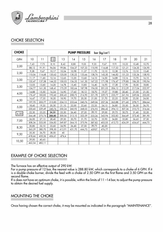
The furnace has an effective output of 290 kW.For a pump pressure of 12 bar, the nearest value is 288.80 kW, which corresponds to a choke of 6 GPH. If itis a double-choke burner, divide the feed with a choke of 2.50 GPH on the first flame and 3.50 GPH on thesecond flame.If is does not have an optimum choke, it is possible, within the limits of 11 –14 bar, to adjust the pump pressureto obtain the desired fuel supply.
Once having chosen the correct choke, it may be mounted as indicated in the paragraph “MAINTENANCE”.
CHOKE PUMP PRESSURE

29
ELECTRODE-DEFLECTOR POSITIONING
After mounting the choke (or chokes), check the correct position of the electrodes and deflector, following thelisted specifications (mm). It is advisable to check the specifications after each intervention on the combustionhead.
ECO 30 ECO 30/2 - ECO 40/2
OPERATION CYCLE
A - flame ignition T1 pre-ventilation time 13 sec. 15 sec.B - presence of flame T2 safety cut-off time 10 sec. 10 sec.C - end of starting procedure T3 pre-ignition time 13 sec. 15 sec.C-D - normal operation T3n post-ignition time 15 sec. 10 sec.D - thermostat shut-down (TA-TC)
ECO 30
Thermostat room temperature - furnace
Motor
Transformer
Electromagnetic valve
Photo resistance
LOA 24 LMO 14

30
ECO 30/2
Thermostat room temperature - furnace
Motor
Transformer
Electromagnetic valve 1° flame
Photo resistance
Thermostat modulation
Air flow control
Electromagnetic valve 2° flame
A - flame ignition T1 pre-ventilation time 13 sec. 15 sec.B - presence of flame T2 safety cut-off time 10 sec. 10 sec.C - end of starting procedure T3 pre-ignition time 13 sec. 15 sec.C-D - normal operation T3n post-ignition time 15 sec. 10 sec.D - thermostat shut-down (TA-TC)
LOA 24 LMO 24

31
ECO 40/2
Thermostat room temperature - furnace
Motor
Transformer
Electromagnetic valve 1° flame
Photo resistance
Thermostat modulation
Air flow control
Electromagnetic valve 2° flame
A - flame ignitionB - presence of flameC - end of starting procedureC-D - normal operationD - thermostat shut-down (TA-TC)
LOA 44 LMO 44T1 pre-ventilation time 25 sec. 26 sec.T2 safety cut-off time 5 sec. 5 sec.T3 pre-ignition time 25 sec. 25 sec.T3n post-ignition time 2 sec. 5 sec.

32
LMO EQUIPMENT
The release pushbutton on the equipment is the main component for accessing all the diagnostic functions(activation and deactivation) as well as for releasing the control and checking device.The release pushbutton has a multicoloured led which indicates the state of the control and checking deviceduring operation and when the diagnostic function is in use.
EQUIPMENT STATE INDICATORSDescription
Condition Colour sequenceStandby, other intermediate states No light Fuel preheating “on”, waiting time 5s.max Yellow Ignition stage Yellow, flashing Correct operation Green Incorrect operation, current level of flame detector below permitted minimum Green, flashing Drop in voltage Alternating yellow red Burner lock out Red Fault (see table on page 8) Red, flashing Stray light before burner ignition Alternating green redRapid flashing for diagnostics Red, rapid flashing
If the burner is locked out, there will be a steady red light on the lock out pushbutton.By pressing the transparent pushbutton, the control and checking device will be released.By pressing it for more than 3 seconds, the diagnosis stage will be activated (red light flashes rapidly).The table below describes the causes of the lock out or fault in relation to the number of flashes (always red).The diagnosis function is interrupted by pressing the release button for at least 3 seconds.
DIAGNOSIS OF LMO EQUIPMENT FAULTS AND LOCK OUTDescription of operating anomalies
Visual indication Possible causes
2 flashes � �
No flame signal- Faulty fuel valves- Faulty flame detector- Incorrect burner setting, no fuel- No ignition
3 flashes � � �
Not used
4 flashes � � � �
Stray light on ignition
5 flashes � � � � �
Not used
6 flashes � � � � � �
Not used
7 flashes � � � � � � �
No flame signal during operation- Faulty fuel valves- Faulty flame detector- Incorrect burner setting, no fuel
8 flashes � � � � � � � �
Anomalies in fuel preheating time
9 flashes � � � � � � � � �
Not used
10 flashes � � � � � � � � � �
Incorrect electrical connection or damage to equipment
33
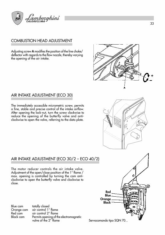
AIR INTAKE ADJUSTMENT (ECO 30)
The immediately accessible micrometric screw, permitsa fine, stable and precise control of the intake airflow.After opening the lock-nut, turn the screw clockwise toreduce the opening of the butterfly valve and anti-clockwise to open the valve, referring to the data plate.
COMBUSTION HEAD ADJUSTMENT
Adjusting screw A modifies the position of the line choke/deflector with regards to the flow nozzle, thereby varyingthe opening of the air intake.
The motor reducer controls the air intake valve.Adjustment of the open/close position of the 1° flame /max. opening is controlled by turning the cam anti-clockwise to open the butterfly valve and clockwise toclose.
AIR INTAKE ADJUSTMENT (ECO 30/2 – ECO 40/2)
Blue cam totally closedOrange cam air control 1° flameRed cam air control 2° flameBlack cam Permits opening of the electromagnetic
valve of the 2° flame Servocomando tipo SQN 70...
RedBlue
OrangeBlack
34
STARTING PROCEDURES
1) PRELIMINARY OPERATIONS
- Mount the pressure gauge and the vacuum gauge on the pump (remove after tune up).- Open the fuel line valve.- Close the thermostat lines (furnace/room temperature)- Attach electricity to the main switch.- Switch to the on position.- Unlock the burner (by pushing the red button)
2) STARTING CYCLE
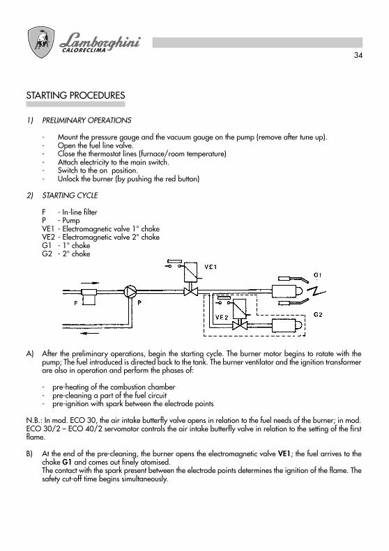
F - In-line filterP - PumpVE1 - Electromagnetic valve 1° chokeVE2 - Electromagnetic valve 2° chokeG1 - 1° chokeG2 - 2° choke
A) After the preliminary operations, begin the starting cycle. The burner motor begins to rotate with thepump; The fuel introduced is directed back to the tank. The burner ventilator and the ignition transformerare also in operation and perform the phases of:
- pre-heating of the combustion chamber- pre-cleaning a part of the fuel circuit- pre-ignition with spark between the electrode points
N.B.: In mod. ECO 30, the air intake butterfly valve opens in relation to the fuel needs of the burner; in mod.ECO 30/2 – ECO 40/2 servomotor controls the air intake butterfly valve in relation to the setting of the firstflame.
B) At the end of the pre-cleaning, the burner opens the electromagnetic valve VE1; the fuel arrives to thechoke G1 and comes out finely atomised.The contact with the spark present between the electrode points determines the ignition of the flame. Thesafety cut-off time begins simultaneously.
35
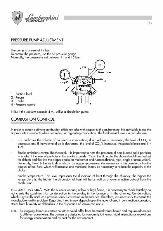
The pump is pre-set at 12 bar.To control the pressure, use the oil pressure gauge.Normally, the pressure is set between 11 and 15 bar.
PRESSURE PUMP ADJUSTMENT
1 - Suction feed2 - Return3 - Choke4 - Pressure control
N.B.: If the vacuum exceeds 4 m., utilise a circulation pump
In order to obtain optimum combustion efficiency, also with respect to the environment, it is advisable to use theappropriate instruments when controlling or regulating combustion. The fundamental levels to consider are:
- CO2 Indicates the volume of air used in combustion; if air volume is increased, the level of CO2 %decreases and if the volume of air is decreased, the level of CO2 % increases. Acceptable levels are 11-12%.
- Smoke emissions control (Bacharach). It is important to note the presence of non-burned solid particlesin smoke. If the level of particles in the smoke exceeds n° 2 on the BH scale, the choke should be checkedfor defects and that it is the proper choke for the burner and furnace (brand, type, angle of atomisation).Generally, the n° BH tends to diminish by raising pump pressure; it is necessary in this case to control theamount of fuel flow, which will increase and therefore, it may be necessary to reduce the capacity of thechoke.
- Smoke temperature. This level represents the dispersion of heat through the chimney; the higher thetemperature is, the higher the dispersion of heat will be as well as a lower effective out-put from thecombustion.
ECO 30/2 – ECO 40/2. With the burners working at low or high flame, it is necessary to check that they donot create the conditions for condensation in the smoke, in the furnace or in the chimney. Condensation,which is typically acid, can provoke serious corrosion in the furnace. Therefore, it is necessary to consult themanufacturer on this problem. Regarding the chimney, depending on the material used in construction, corrosion,stains from humidity or difficulties in the dispersion of smoke can occur.
N.B. : Existing regulations in certain countries could differ from the stated values herein and require adherenceto different parameters. The burners are designed for conformity to the most rigid international regulationsfor energy conservation and respect for the environment.
COMBUSTION CONTROL

36
All operations should be performed with the electrical supply disconnected. After removing the casing, it ispossible to clean the photo resistance, inspect the motor, the electromagnetic valve, the transformer and the airintake control.To reach the fan and butterfly valve, the over-head plate and component mount must beremoved.This will be attached in the standard service position.This operation will also make the combustionhead easy to remove.To clean and inspect the choke-electrode, normally, one should extract the head group by moving the over-head plate.
MAINTENANCE
Unscrew from position and clean the photosensitive window with a dry cloth.
PHOTO RESISTANCE
Close the fuel line valve, take off the pump cover, take out the filter, clean it with gasoline, rinse it with light oiland re-assemble carefully.
PUMP FILTER
Close the fuel line valve, take off the filter cover, unscrew the filter, and clean the filter carefully. Re-assemblecarefully.
FUEL LINE FILTER
It is sufficient of take off the cover in order to reach the main components. Maintenance of the combustion headshould be carried out as follows:
● Take out the screws and take off the cover.● Unscrew and take out the over-head plate and place it in service position.● In order to reach the fan, remove the screws from the lower plate to unhook the electrical coupling.
FAN & BUTTERFLY VALVE
37
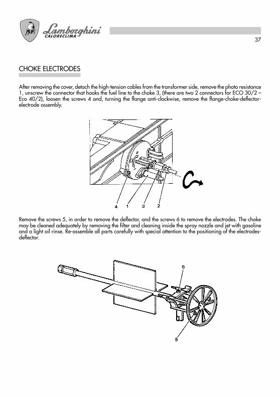
After removing the cover, detach the high-tension cables from the transformer side, remove the photo resistance1, unscrew the connector that hooks the fuel line to the choke 3, (there are two 2 connectors for ECO 30/2 –Eco 40/2), loosen the screws 4 and, turning the flange anti-clockwise, remove the flange-choke-deflector-electrode assembly.
Remove the screws 5, in order to remove the deflector, and the screws 6 to remove the electrodes. The chokemay be cleaned adequately by removing the filter and cleaning inside the spray nozzle and jet with gasolineand a light oil rinse. Re-assemble all parts carefully with special attention to the positioning of the electrodes-deflector.
CHOKE ELECTRODES
38
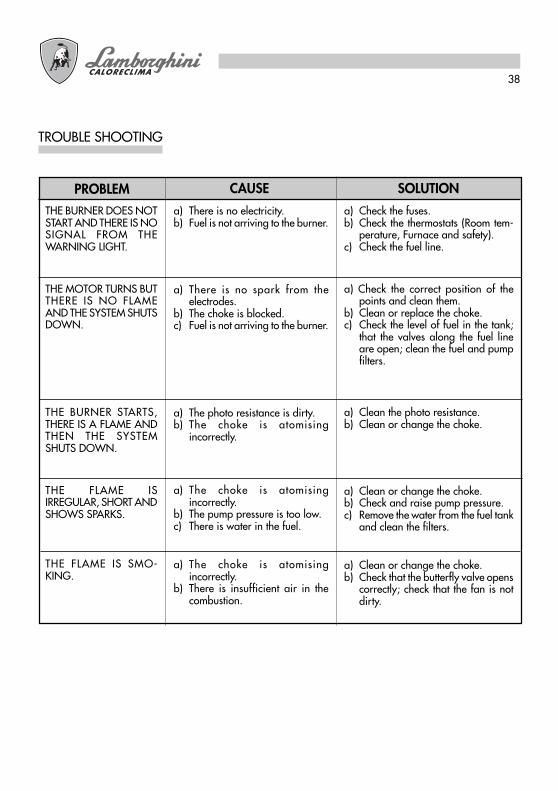
TROUBLE SHOOTING
SOLUTIONCAUSEPROBLEMa) There is no electricity.b) Fuel is not arriving to the burner.
a) There is no spark from theelectrodes.
b) The choke is blocked.c) Fuel is not arriving to the burner.
a) The photo resistance is dirty.b) The choke is atomising
incorrectly.
a) The choke is atomisingincorrectly.
b) The pump pressure is too low.c) There is water in the fuel.
a) The choke is atomisingincorrectly.
b) There is insufficient air in thecombustion.
THE BURNER DOES NOTSTART AND THERE IS NOSIGNAL FROM THEWARNING LIGHT.
THE MOTOR TURNS BUTTHERE IS NO FLAMEAND THE SYSTEM SHUTSDOWN.
THE BURNER STARTS,THERE IS A FLAME ANDTHEN THE SYSTEMSHUTS DOWN.
THE FLAME ISIRREGULAR, SHORT ANDSHOWS SPARKS.
THE FLAME IS SMO-KING.
a) Check the fuses.b) Check the thermostats (Room tem-
perature, Furnace and safety).c) Check the fuel line.
a) Check the correct position of thepoints and clean them.
b) Clean or replace the choke.c) Check the level of fuel in the tank;
that the valves along the fuel lineare open; clean the fuel and pumpfilters.
a) Clean the photo resistance.b) Clean or change the choke.
a) Clean or change the choke.b) Check and raise pump pressure.c) Remove the water from the fuel tank
and clean the filters.
a) Clean or change the choke.b) Check that the butterfly valve opens
correctly; check that the fan is notdirty.
Lire attentivement les instructions et les avertissements contenus dans ce manuel, car ilsproportionnent d’importantes indications concernant la sécurité de montage, d’emploi etd’entretien. Garder avec soin ce manuel pour toute autre consultation. Seulement le personnelqualifié, qui sera responsable du respect des lois de sécurité en vigeur, peut réaliser lemontage.
F

40
Félicitations...… Pour votre excellent choix. Nous vous remercions de la préférence accordée à nos produits. À
partir de 1959 LAMBORGHINI CALORECLIMA est activement présente en Italie et dans le monde entier,grâce à un réseau capillaire d’Agents et de concessionaires très étendu assurant constamment la présencede ses produits sur le marché.Un service d’assistence technique, “LAMBORGHINI SERVICE”, qui s’occupe de l’entretien du produit,supporte cette service.
INDEX PAGE
CARACTÉRISTIQUES TECNIQUES ___________________ 41DIMENSIONS ___________________________________ 41PLAGES DE TRAVAIL ______________________________ 42MONTAGE À LA CHAUDIÈRE ______________________ 42CONNEXIONS ÉLECTRIQUES ______________________ 43ALIMENTATION FIOUL DOMESTIQUE _______________ 45ALIMENTATION MONOTUBE ______________________ 45ALIMENTATION DOUBLE TUBE _____________________ 45CHOIX GICLEUR _________________________________ 46EXEMPLE CHOIX GICLEUR _________________________ 46MONTAGE GICLEUR _____________________________ 46POSITIONNEMENT ÉLECTRODES - ACCROCHE-FLAMME ___ 47CYCLE DE FONCTIONNEMENT ____________________ 47APPAREIL LMO___________________________________ 50RÉGLAGE TÊTE __________________________________ 51RÉGLAGE AIR DE COMBUSTION (ECO 30) __________ 51RÉGLAGE AIR DE COMBUSTION (ECO 30/2 – ECO 40/2) __ 51MISE EN MARCHE _______________________________ 52RÉGLAGE PRESSION POMPE ______________________ 53CONTRÔLE COMBUSTION ________________________ 53ENTRETIEN ______________________________________ 54PHOTORÉSISTANCE ______________________________ 54FILTRE POMPE ___________________________________ 54FILTRE DE LIGNE _________________________________ 54VENTILATEUR CLAPET D’AIR _______________________ 54ÉLECTRODES GICLEUR ____________________________ 55ANOMALIES DE FONCTIONNEMENT _______________ 56
Pour le montage et pour le positionnement de la chaudièreSUIVRE SCRUPULEUSEMENT LES LOIS LOCALES EN VIGUEUR
41
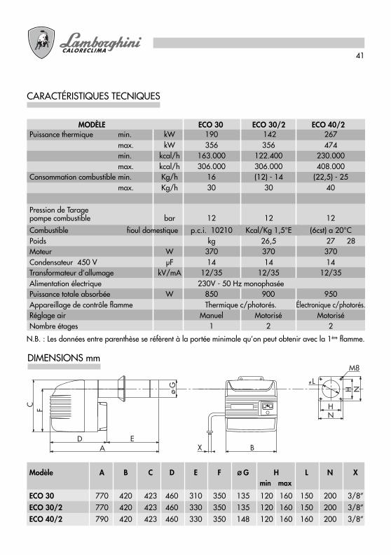
CARACTÉRISTIQUES TECNIQUES
N.B. : Les données entre parenthèse se réfèrent à la portée minimale qu’on peut obtenir avec la 1ère flamme.
DIMENSIONS mm
X
F H
L
M8
N
A B
C
ED
H Nø G
min maxModèle A B C D E F Ø G H L N X
ECO 30 770 420 423 460 310 350 135 120 160 150 200 3/8”ECO 30/2 770 420 423 460 330 350 135 120 160 150 200 3/8”ECO 40/2 790 420 423 460 330 350 148 120 160 160 200 3/8”
MODÈLE ECO 30 ECO 30/2 ECO 40/2Puissance thermique min. kW 190 142 267
max. kW 356 356 474min. kcal/h 163.000 122.400 230.000max. kcal/h 306.000 306.000 408.000
Consommation combustible min. Kg/h 16 (12) - 14 (22,5) - 25max. Kg/h 30 30 40
Pression de Taragepompe combustible bar 12 12 12
Combustible fioul domestique p.c.i. 10210 Kcal/Kg 1,5°E (6cst) a 20°CPoids kg 26,5 27 28Moteur W 370 370 370Condensateur 450 V µF 14 14 14Transformateur d’allumage kV/mA 12/35 12/35 12/35Alimentation électrique 230V - 50 Hz monophaséePuissance totale absorbée W 850 900 950Appareillage de contrôle flamme Thermique c/photorés. Électronique c/photorés.Réglage air Manuel Motorisé MotoriséNombre étages 1 2 2
42
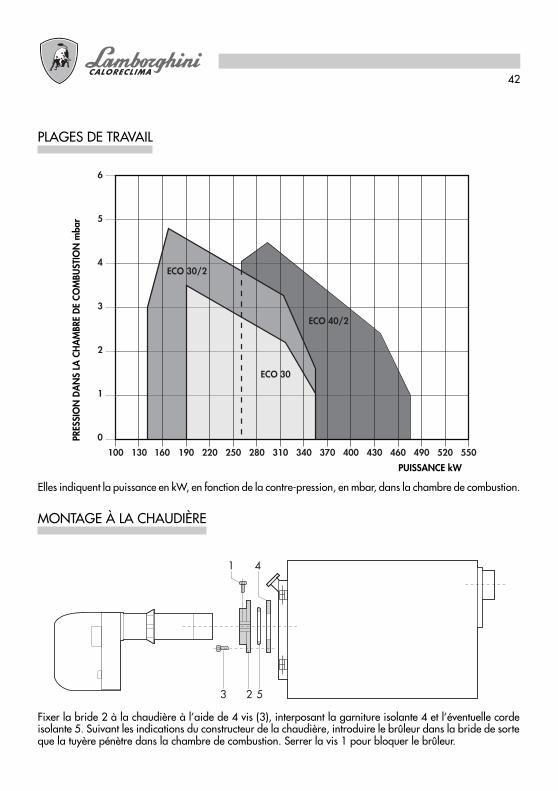
PLAGES DE TRAVAIL
Elles indiquent la puissance en kW, en fonction de la contre-pression, en mbar, dans la chambre de combustion.
ECO 30
100 130 160 190 220 250 280 310 340 370 400 430 460 490 520 550POTENZA kW
6
4
3
2
1
0PRES
SIO
NE
IN C
AM
ERA
DI C
OM
BUST
ION
E m
bar
ECO 40/2
5
ECO 30/2
MONTAGE À LA CHAUDIÈRE
Fixer la bride 2 à la chaudière à l’aide de 4 vis (3), interposant la garniture isolante 4 et l’éventuelle cordeisolante 5. Suivant les indications du constructeur de la chaudière, introduire le brûleur dans la bride de sorteque la tuyère pénètre dans la chambre de combustion. Serrer la vis 1 pour bloquer le brûleur.
1 4
3 2 5
PUISSANCE kW
PRES
SIO
N D
AN
S LA
CH
AM
BRE
DE
COM
BUST
ION
mba
r

43
CONNEXIONS ÉLECTRIQUES
Les connexions que l’installateur doit réaliser sont:
● ligne d’alimentation● ligne thermostatique● éventuelle lampe de blocage● éventuel horloge● éventuel thermostat modulation flamme
(enlever le câble qui sert de barrette)
REMARQUE: Il est nécessaire de suivre scrupuleusement la règle indiquant la connexion de deux câbles aumaximum pour chaque borne.
Attention:
● ne pas inverser le neutre et la phase● réaliser une parfaite connexion à la terre● suivre les normes techniques et les lois locales en vigueur.
ECO 30
MPELOA 24.../LMO14...
LÉGENDE
F FusibleFA Filtre antiparasiteFCA Fusible circuit auxiliaireFR PhotorésistanceIG Interrupteur généralIMA Interrupteur marche-arrêt
MB Moteur brûleurMPE Tableau à bornes Appareillage LandisTC Thermostat chaudièreTS Thermostat de sécuritéTR Transformateur d’allumageVE Valve Électromagnétique

44
Les connexions que l’installateur doit réaliser sont:
● ligne d’alimentation● ligne thermostatique● éventuelle lampe de blocage● éventuel horloge● éventuel thermostat modulation flamme
(enlever le câble qui sert de barrette)
REMARQUE: Il est nécessaire de suivre scrupuleusement la règle indiquant la connexion de deux câbles aumaximum pour chaque borne.
Attention:● ne pas inverser le neutre et la phase● réaliser une parfaite connexion à la terre● suivre les normes techniques et les lois locales en vigueur.
ECO 30/2 - ECO 40/2
1 2 2 3 4 5 6 7 8 10 11 129
M
MB
VE1
TC
TS F IG
B4
T2T1N
L1
S3
L
N
FR
2
IMA
3 5 6 1 8 N4 7 MMS
VE2
TR
FA
FCA
2 3 4 5 6 71 8 9
2N
ImM
TMF
31
L1
LÉGENDE
F FusibleFA Filtre antiparasiteFCA Fusible circuit auxiliaireFR PhotorésistanceIG Interrupteur généralIma Interrupteur marche-arrêtImM Interrupteur comande marche
mini - maxiMB Moteur brûleur
MMS Tableau à bornes Moteurservocommande air
MPE Tableau à bornes Appareillage LandisTC Thermostat chaudièreTMF Thermostat modulation 2ème allure (éventuel)TS Thermostat de sécuritéTR Transformateur d’allumageVE1 Valve Électromagnétique 1ère allureVE2 Valve Électromagnétique 2ème allure
MPELOA 24.../LMO24...(ECO 30/2)LOA 44.../LMO44...(ECO 40/2)

45
ALIMENTATION FIOUL DOMESTIQUE
Les dimensions des tuyauteries (diamètre/longueur) sont en relation avec le type d’installation (avec un/deuxtuyaux, en aspiration/chute) et avec les caractéristiques de la pompe.Le diagramme indique la longueur L maximale permise d’une ligne d’aspiration, en fonction de la dénivellationH et du diamètre interne du tuyau d, pour une pression atmosphérique de 1013 mbar et un vide de 0,45 baret considérant le montage de 4 coudes, d’une soupape de blocage et d’une soupape de non-retour.
ALIMENTATION MONOTUBE
Nous vous conseillons d’éviter, autant que possible, cette solution car si elle n’est pas parfaitement réalisée ellepeut causer de considérables anomalies au brûleur. Si, toutefois, il n’est pas possible d’éviter ce type demontage, il faut: réaliser seulement des installations à chute; modifier les pompes enlevant le grain interne;prévoir des nettoyages appropriés dans les points les plus hauts de la tuyauterie et éviter la formation de sacsd’air.
ALIMENTATION DOUBLE TUBE
N.B.: Si la longueur de la tuyauterie dépasse 60 m., nous vous conseillons une pompe d’alimentation –d10/2, d12/2: pour les brûleurs à deux flammes.
46
PRESSIONE POMPA bar (kg/cm2 )UGELLO
GPH
2,00
2,50
3,00
3,50
4,00
4,50
5,00
6,00
7,00
8,30
9,50
10,50
10 11 12 13 14 15 16 17 18 19 20 21
7,43 7,75 8,10 8,42 8,80 9,05 9,35 9,67 9,91 10,22 10,48 10,70
88,12 91,91 96,06 99,86 104,37 107,33 110,90 114,68 117,53 121,21 124,30 126,909,28 9,67 10,17 10,54 10,98 11,27 11,70 12,10 12,38 12,76 13,10 13,40
110,06 114,68 120,62 125,00 130,22 133,66 138,76 143,50 146,82 151,33 155,36 158,9211,17 11,60 12,16 12,65 13,20 13,60 14,10 14,50 14,88 15,16 15,70 16,10
132,47 137,58 144,22 150,03 156,55 161,30 167,22 171,98 176,47 179,80 186,20 190,9413,05 13,60 14,20 14,78 15,40 15,85 16,40 16,95 17,38 17,90 18,30 18,80
154,77 161,30 168,41 175,29 182,64 187,98 194,50 201,03 206,12 212,29 217,04 222,97
14,88 15,50 16,24 16,90 17,60 18,12 18,70 19,37 19,88 20,40 21,00 21,50176,47 183,83 192,60 200,43 208,73 214,90 221,78 229,73 235,77 241,94 249,06 255,0016,67 17,35 18,20 18,90 19,70 20,30 21,00 21,70 22,25 22,90 23,50 24,00
197,70 205,77 215,85 224,15 233,64 240,76 249,06 257,36 263,88 271,60 278,71 284,6418,60 19,35 20,30 21,10 22,00 22,60 23,35 24,15 24,80 25,50 26,20 26,70
220,60 229,49 240,76 250,24 260,92 268,03 286,42 294,13 307,36 310,73 316,6622,30 23,25 24,35 25,30 26,40 27,20
276,9329,00 29,75 30,75 31,40 32,20
264,48 275,74 288,80 300,06 313,10 322,59
28,10
343,94 352,83 364,49 372,40 381,9026,00 27,15 28,40 29,50 30,70 31,70
333,2633,90 34,80 35,80 36,65 37,50
308,36 322,00 336,82 349,87 364,10 375,9632,70
402,05 412,73 424,59 434,67 444,7530,80 32,10 33,60 34,90 36,40 37,50
387,8240,20
365,29 380,70 398,50 413,91 431,70 444,75
38,75
476,7735,30 36,70 38,50 40
45957
418,66 435,26 456,61 474,439,00 40,65
462,54 482,11
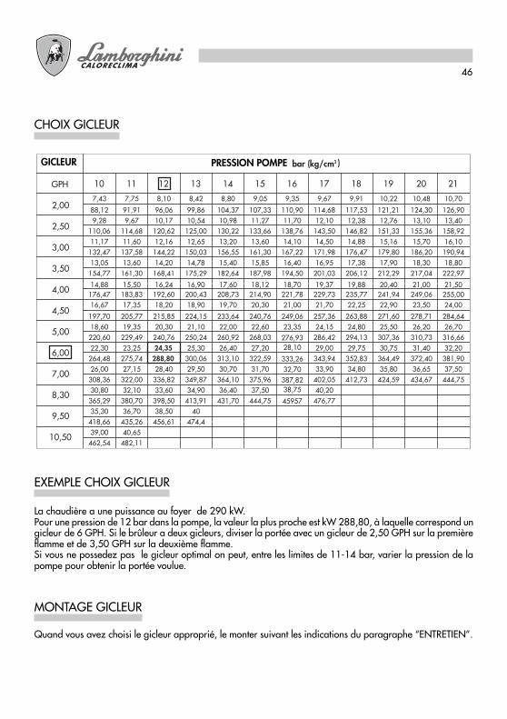
CHOIX GICLEUR
EXEMPLE CHOIX GICLEUR
MONTAGE GICLEUR
La chaudière a une puissance au foyer de 290 kW.Pour une pression de 12 bar dans la pompe, la valeur la plus proche est kW 288,80, à laquelle correspond ungicleur de 6 GPH. Si le brûleur a deux gicleurs, diviser la portée avec un gicleur de 2,50 GPH sur la premièreflamme et de 3,50 GPH sur la deuxième flamme.Si vous ne possedez pas le gicleur optimal on peut, entre les limites de 11-14 bar, varier la pression de lapompe pour obtenir la portée voulue.
Quand vous avez choisi le gicleur approprié, le monter suivant les indications du paragraphe “ENTRETIEN”.
GICLEUR PRESSION POMPE

47
POSITIONNEMENT ÉLECTRODES – ACCROCHE-FLAMME
Après avoir monté le gicleur (ou les gicleurs), vérifier la position des électrodes et de l’accroche-flamme selonles cotes indiquées (mm). Il est nécessaire de réaliser un contrôle des cotes après chaque intervention sur latête.
ECO 30 ECO 30/2 - ECO 40/2
CYCLE DE FONCTIONNEMENT
ECO 30
Thermostat amb. – chaudière
Moteur
Transformateur
Valve électromagnétique
Photorésistance
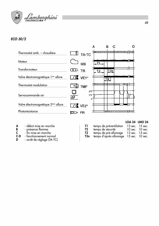
A - début mise en marcheB - présence flammeC - fin mise en marcheC-D - fonctionnement normalD - arrêt de réglage (TA-TC)
T1 temps de préventilation 13 sec. 15 sec.T2 temps de sécurité 10 sec. 10 sec.T3 temps de préallumage 13 sec. 15 sec.T3n temps d’après allumage 15 sec. 10 sec.
LOA 24 LMO 14
48
ECO 30/2
Thermostat amb. – chaudière
Moteur
Transformateur
Valve électromagnétique 1ère allure
Photorésistance
Thermostat modulation
Servocommande air
Valve électromagnétique 2ème allure
A - début mise en marcheB - présence flammeC - fin mise en marcheC-D - fonctionnement normalD - arrêt de réglage (TA-TC)
T1 temps de préventilation 13 sec. 15 sec.T2 temps de sécurité 10 sec. 10 sec.T3 temps de pré-allumage 13 sec. 15 sec.T3n temps d’après allumage 15 sec. 10 sec.
LOA 24 LMO 24

49
ECO 40/2
Thermostat amb. – chaudière
Moteur
Transformateur
Valve électromagnétique 1ère allure
Photorésistance
Thermostat modulation
Servocommande air
Valve électromagnétique 2ème allure
A - début mise en marcheB - présence flammeC - fin mise en marcheC-D - fonctionnement normalD - arrêt de réglage (TA-TC)
LOA 44 LMO 44T1 temps de préventilation 25 sec. 26 sec.T2 temps de sécurité 5 sec. 5 sec.T3 temps de pré-allumage 25 sec. 25 sec.T3n temps d’après allumage 2 sec. 5 sec.

50
APPAREIL LMO
Le bouton de déclenchement de l’appareil est l’élément principal pour pouvoir accéder à toutes les fonctionsde diagnostic (activation et désactivation) et pour pouvoir débloquer le dispositif de commande et de contrôle.Le bouton de déclenchement est muni d’une Led multicolore qui indique l’état du dispositif de commande et decontrôle pendant le fonctionnement et pendant la phase de diagnostic.
INDICATIONS SUR L’ETAT DE L’APPAREILTableau récapitulatif
Condition Séquence des couleurs
Condition d’attente, autres états intermédiaires Pas de lumière
Préchauffage du combustible “Connecté”, tempsd’attente 5 sec. maxi.
Jaune
Phase d’allumage Lumière jaune intermittente
Fonctionnement correct Vert
Dysfonctionnement, intensité de courant dudétecteur de flamme inférieure à l’intensité minimaleadmise.
Lumière verte intermittente
Baisse de la tension d’alimentation Lumière jaune/rouge alternée
Condition de mise en sécurité du brûleur Rouge
Signalisation de panne (voir tableau page 8). Lumière rouge intermittente
Lumière parasite avant la mise en marche dubrûleur.
Lumière verte/rouge alternée
Intermittence rapide pour diagnostic Lumière rouge à intermittencerapide
En cas de mise en sécurité du brûleur, la lumière rouge du bouton de mise en sécurité sera fixe.En enfonçant le bouton transparent, on débloque le dispositif de commande et de contrôle.Une pression d’une durée supérieure à 3 secondes active la phase de diagnostic (lumière rouge à intermittencerapide). Les causes à l’origine d’une mise en sécurité ou d’un dysfonctionnement sont indiquées dans letableau ci-après, en fonction du nombre de clignotements (de couleur rouge toujours).En enfonçant la touche de déblocage pendant 3 secondes au moins, la fonction de diagnostic s’interrompt.
DIAGNOSTIC DES CAUSES A L’ORIGINE D’UN DYSFONCTIONNEMENT OU D’UNE MISE EN SECURITEDE L’APPAREIL LMO
Récapitulation des pannes de fonctionnement
Indication optique Causes éventuelles
2 clignotements � �
Absence du signal de flamme- Dysfonctionnement des vannes du combustible.- Dysfonctionnement du détecteur de présence de
flamme.- Défectuosité au niveau du réglage du brûleur, absence
de combustible.- Raté d’allumage.
3 clignotements � � �
Libre.
4 clignotements � � � �
Lumière étrangère à l’allumage.
5 clignotements � � � � �
Libre.
6 clignotements � � � � � �
Libre.
7 clignotements � � � � � � �
Absence du signal de flamme pendant le fonctionnement.- Dysfonctionnement des vannes du combustible.- Dysfonctionnement du détecteur de flamme.- Défectuosité au niveau du réglage du brûleur, absence
de combustible.
8 clignotements � � � � � � � �
Irrégularité du temps de préchauffage du combustible.
9 clignotements � � � � � � � � �
Libre.
10 clignotements � � � � � � � � � �
Erreurs au niveau du branchement électrique ou pannesde l’appareil.
51
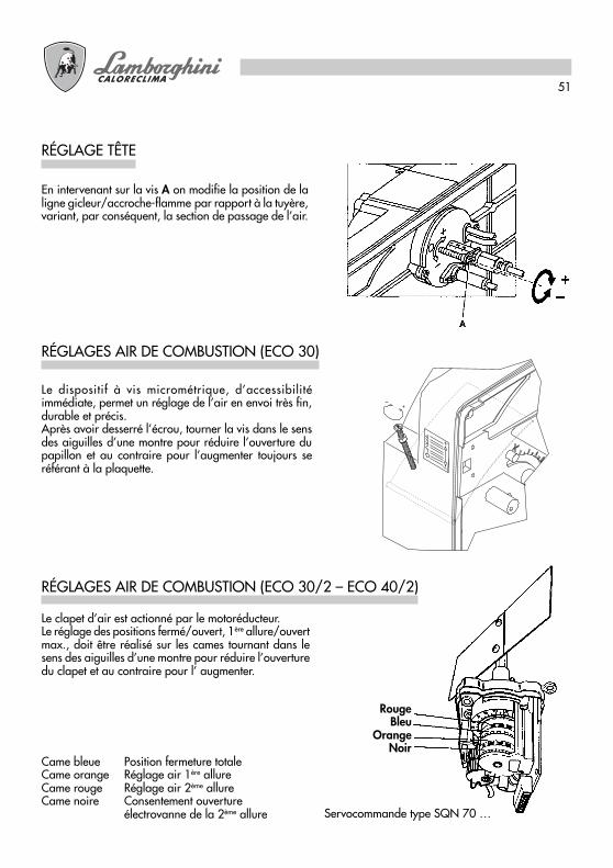
RÉGLAGES AIR DE COMBUSTION (ECO 30)
Le dispositif à vis micrométrique, d’accessibilitéimmédiate, permet un réglage de l’air en envoi très fin,durable et précis.Après avoir desserré l’écrou, tourner la vis dans le sensdes aiguilles d’une montre pour réduire l’ouverture dupapillon et au contraire pour l’augmenter toujours seréférant à la plaquette.
RÉGLAGE TÊTE
En intervenant sur la vis A on modifie la position de laligne gicleur/accroche-flamme par rapport à la tuyère,variant, par conséquent, la section de passage de l’air.
Le clapet d’air est actionné par le motoréducteur.Le réglage des positions fermé/ouvert, 1ère allure/ouvertmax., doit être réalisé sur les cames tournant dans lesens des aiguilles d’une montre pour réduire l’ouverturedu clapet et au contraire pour l’ augmenter.
RÉGLAGES AIR DE COMBUSTION (ECO 30/2 – ECO 40/2)
Came bleue Position fermeture totaleCame orange Réglage air 1ère allureCame rouge Réglage air 2ème allureCame noire Consentement ouverture
électrovanne de la 2ème allure Servocommande type SQN 70 …
RougeBleu
OrangeNoir
52
MISE EN MARCHE
1) OPÉRATIONS PRÉLIMINAIRES
- monter le manomètre et le vacuomètre sur la pompe (enlever après la mise au point)- ouvrir les vannes le long de la tuyauterie du fioul domestique.- fermer la ligne des thermostats (chaudière/ambiance)- envoyer courant de l’interrupteur général- mettre en position de marche l’interrupteur- débloquer l’appareillage (appuyant sur le poussoir rouge)
2) MISE EN MARCHE
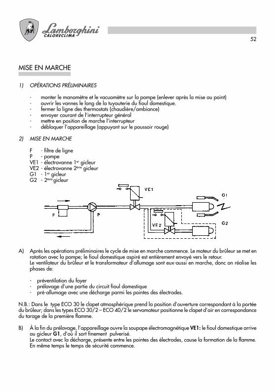
F - filtre de ligneP - pompeVE1 - électrovanne 1er gicleurVE2 - électrovanne 2ème gicleurG1 - 1er gicleurG2 - 2ème gicleur
A) Après les opérations préliminaires le cycle de mise en marche commence. Le moteur du brûleur se met enrotation avec la pompe; le fioul domestique aspiré est entièrement envoyé vers le retour.Le ventilateur du brûleur et le transformateur d’allumage sont eux-aussi en marche, donc on réalise lesphases de:
- préventilation du foyer- prélavage d’une partie du circuit fioul domestique- pré-allumage avec une décharge parmi les pointes des électrodes.
N.B.: Dans le type ECO 30 le clapet atmosphérique prend la position d’ouverture correspondant à la portéedu brûleur; dans les types ECO 30/2 – ECO 40/2 le servomoteur positionne le clapet d’air en correspondancedu tarage de la première flamme.
B) À la fin du prélavage, l’appareillage ouvre la soupape électromagnétique VE1: le fioul domestique arriveau gicleur G1, d’où il sort finement pulverisé.Le contact avec la décharge, présente entre les pointes des électrodes, cause la formation de la flamme.En même temps le temps de sécurité commence.

53
La pompe est pré-réglée à 12 BAR.Pour le contrôle de la pression utiliser un manomètre à bain d’huile.La pression peut être normalement réglée entre 11 et 15 bar.
RÉGLAGE PRESSION POMPE
1 – Aspiration2 – Retour3 – Gicleur4 – Réglage pression
N.B. Si le vide dépasse 4 m. prévoir una pompe de circulation.
Nous vous conseillons de réaliser, à l’aide des instruments appropriés, le contrôle et le réglage de la combustionpour obtenir les rendements de combustion les meilleures. Les valeurs fondamentales à considérer sont:
- CO2 . Il indique avec quel excès d’air la combustion se réalise; si on augmente l’air la valeur de CO2 %baisse et si on baisse l’air de combustion CO2 % augmente. Les valeurs acceptables sont 11-12%.
- Le nombre de fumée (Bacharach). Il indique que dans les fumées il y a des particules d’imbrûlé solide. Sion dépasse le n°2 de l’échelle BH il est nécessaire de contrôler que le gicleur ne soit pas défectueux etqu’il soit indiqué pour le brûleur et pour la chaudière (marque, type, angle de pulverisation). En généralle n° BH baisse si on augmente la pression dans la pompe; en ce cas il est nécessaire de faire attention àla portée du combustible qui augmente, et donc, éventuellement, réduire la capacité du gicleur .
- Température des fumées. C’est une valeur représentant la dispersion de chaleur à travers la cheminée;plus la température est haute plus les dispersions sont élevées et le rendement de combustion est bas.
ECO 30/2 – ECO 40/2. Avec les brûleurs marchant à haute/basse flamme, il est nécessaire de s’assurer qu’ilne se créent pas les conditions pour la condensation des fumées aussi bien dans la chaudière que dans lacheminée. Puisque la condensation est du type acide, elle pourrait causer de graves corrosions à la chaudièreet donc il est nécessaire de consulter le constructeur. En ce qui concerne la cheminée, selon le matériel utilisépour sa construction, on peut avoir des phénomènes de corrosion, des taches d’humidité de couleur sombre etune difficulté dans l’écoulement des fumées (tirage insuffisant).
N.B. Les lois en vigeur dans quelques pays peuvent demander aussi bien d’autres réglages (différents queceux détaillés dans ce manuel) que le respect d’autres paramètres. Les brûleurs sont projetés pourrespecter les lois internationales les plus rigoureuses concernant l’économie d’énergie et la sauvegardedu milieu.
CONTRÔLE COMBUSTION
54
Toutes les opérations doivent être réalisées après avoir coupé la courant. En enlevant le capot on peut nettoyerla photorésistance, contrôler le moteur, la soupape électromagnétique, le transformateur et la servocommandeclapet d’air. Pour accéder au ventilateur et au clapet d’air on doit extraire le groupe plaque et porte-composantsqui sera accroché dans la position de service prévue. Grâce à cette opération on peut accéder complètementà la tête.Pour réaliser le nettoyage/contrôle du gicleur – électrodes, normalement on doit extraire le groupe tête enenlevant la plaque supérieure.
ENTRETIEN
L’ôter de sa place et nettoyer, à l’aide d’un chiffon sec, sa partie sensible.
PHOTORÉSISTANCE
Fermer la vanne sur l’aspiration, démonter le couvercle de la pompe, extraire la cartouche à filet, la laver àl’aide d’essence et la rincer utilisant le fioul domestique. Remonter le tout avec soin.
FILTRE POMPE
Fermer la vanne sur l’aspiration, démonter le panier du filtre, normalement vissé sur le corps filtre et nettoyersoigneusement le filet filtrant . Remonter le tout avec soin.
FILTRE DE LIGNE
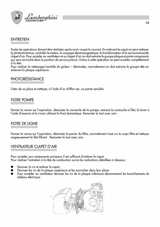
Pour accéder aux composants pricipaux il est suffisant d’enlever le capot.Pour réaliser l’entretien à la tête de combustion suivre les indications détaillées ci-dessous :
● Devisser la vis et enlever le capot.● Devisser les vis de la plaque supérieure et les accrocher dans leur place.● Pour accéder au ventilateur devisser les vis de la plaque inférieure déconnectant les branchements du
tableau éléctrique.
VENTILATEUR CLAPET D’AIR

55
Après avoir enlevé le capot ôter les câbles de haute tension du côté transformateur, enlever la photorésistance1, devisser le raccord 2 qui réunit le tuyau du fioul domestique à la ligne 3 du gicleur (les raccords sont 2 pourECO 30/2 – ECO40/2), desserrer les vis 4 et tournant la bride dans le sens contraire à celui des aiguillesd’une montre extraire le groupe bride – gicleur - accroche-flamme - électrodes.
Devisser la vis 5 pour enlever l’accroche-flamme et la vis 6 pour enlever les électrodes. On peut réaliser un bonnettoyage démontant le filtre et nettoyant les taillages et le trou de pulverisation à l’aide d’essence et le rincerà l’aide de fioul domestique. Quand on doit tout remonter faire attention au correct positionnement desélectrodes – accroche-flamme.
ÉLECTRODES – GICLEUR

56
ANOMALIES DE FONCTIONNEMENT
SOLUTIONSCAUSESPROBLÈMES
a) Manque d’énergie électriqueb) Le combustible n’arrive pas au
brûleur
a) La décharge des électrodes nese réalise pas.
b) Gicleur obturéc) Le combustibile n’arrive pas.
a) Photorésistance sale.b) Gicleur qui pulvérise mal.
a) Le gicleur pulvérise malb) La pression dans la pompe est
trop basse.c) Il y a de l’eau dans le fioul
domestique
a) Le gicleur pulvérise mal.b) Peu d’air de combustion.
LE BRÛLEUR NE MARCHEPAS ET IL N’Y A PAS LASIGNALISATION DEBLOCAGE
LE MOTEUR MARCHE,MAIS IL N’Y A PAS LAFORMATION DE LAFLAMME, AVEC L’ARRÊTBLOQUÉ.
LE BRÛLEUR SE MET ENMARCHE, IL Y A LAFORMATION DE LAFLAMME ET PUIS ILS’ARRÊTE SEBLOQUEANT
LA FLAMME ESTIRRÉGULIÈRE, COURTEAVEC ÉTINCELLES.
LA FLAMME ESTFUMEUSE
a) Contrôler les fusiblesb) Contrôler les thermostats
(ambiance, chaudière, sécurité)c) Contrôler la ligne d’alimentation.
a) Contrôler la correcte position despointes et les nettoyer.
b) Nettoyer et remplacer le gicleurc) Contrôler le niveau du fioul
domestique dans la citerne ;contrôler que les vannes le long dela ligne fioul domestique soientouvertes ; contrôler le nettoyage dufiltre de ligne et de la pompe.
a) Nettoyer la photorésistanceb) Nettoyer ou remplacer le gicleur
a) Nettoyer ou remplacer le gicleurb) Contrôler et augmenter la pression.c) Faire enlever l’eau de la citerne et
nettoyer les filtres.
a) Nettoyer ou remplacer le gicleurb) Contrô ler que le c lapet
atmosphérique ouvre régulièrement ;contrôler que le ventilateur nesoit pas sale.
Die in dieser Anleitung enthaltenen Anweisungen und Hinweise lesen, da sie wichtigeAngaben zur Sicherheit, Verwendung und Wartung liefern. Das Handbuch ist zumNachschlagen sorgfältig aufzubewahren. Die Installation muss von qualifiziertem Perso-nal vorgenommen werden, das für die Einhaltung der geltenden Sicherheitsvorschriftenverantwortlich ist.
D
58
Glückwünsche...... für die ausgezeichnete Wahl. Wir danken Ihnen für den Vorzug, den Sie unseren Produkten
gewährt haben. LAMBORGHINI CALORE CLIMA ist seit 1959 mit einem kapillaren Netz von Vertreternund Konzessionären auf dem italienischen und weltweiten Markt aktiv, dank der eine ständige Anwesenheitdes Produkts auf dem Markt gewährleistet wird.Der technische Kundendienst LAMBORGHINI SERVICE unterstützt Sie mit einer qualifizierten Wartungdes Produkts.
INHALTSVERZEICHNIS SEITE
TECHNISCHE DATEN _____________________________ 59ABMESSUNGEN _________________________________ 59ARBEITSKURVEN _________________________________ 60MONTAGE AM KESSEL ___________________________ 60ELEKTROANSCHLÜSSE ____________________________ 61GASÖLZUFÜHRUNG _____________________________ 63ZUFÜHRUNG ÜBER EINE LEITUNG __________________ 63ZUFÜHRUNG ÜBER ZWEI LEITUNGEN ______________ 63WAHL DER DÜSEN _______________________________ 64BEISPIEL EINER DÜSENWAHL ______________________ 64MONTAGE DER DÜSE ____________________________ 64AUSRICHTEN DER ELEKTRODEN – ABWEISER ________ 65BETRIEB _________________________________________ 65LMO GERÄT_____________________________________ 68EINSTELLEN DES BRENNERKOPFES _________________ 69EINSTELLEN DER VERBRENNUNGSLUFT (ECO 30)_____ 69EINSTELLEN DER VERBRENNUNGSLUFT (ECO 30/2 – ECO 40/2) _ 69INBETRIEBNAHME________________________________ 70EINSTELLEN DES PUMPENDRUCKS _________________ 71VERBRENNUNGSKONTROLLE _____________________ 71WARTUNG______________________________________ 72LICHTELEKTRISCHER WIDERSTAND _________________ 72PUMPENFILTER___________________________________ 72LINIENFILTER ____________________________________ 72LUFTKLAPPEN-FLÜGELRAD ________________________ 72ELEKTRODEN – DÜSE _____________________________ 73BETRIEBSSTÖRUNGEN ____________________________ 74
Für die Installation und die Aufstellung des Brenners sind dieGELTENDEN VORSCHRIFTEN STRIKT EINZUHALTEN.

59
TECHNISCHE DATEN
N.B.: Die in Klammern aufgeführten Daten beziehen sich auf die mit der 1. Flamme mögliche Mindestleistung.
ABMESSUNGEN in mm
X
F H
L
M8
N
A B
C
ED
H Nø G
min maxModell A B C D E F Ø G H L N X
ECO 30 770 420 423 460 310 350 135 120 160 150 200 3/8”ECO 30/2 770 420 423 460 330 350 135 120 160 150 200 3/8”ECO 40/2 790 420 423 460 330 350 148 120 160 160 200 3/8”
MODELL ECO 30 ECO 30/2 ECO 40/2Thermische Leistung min. kW 190 142 267
max. kW 356 356 474min. kcal/h 163.000 122.400 230.000max. kcal/h 306.000 306.000 408.000
Brennstoffverbrauch min. Kg/h 16 (12) - 14 (22,5) - 25max. Kg/h 30 30 40
Eichdruck derBrennstoffpumpe bar 12 12 12
Brennstoff Gasöl Heizwert 10210 Kcal/Kg 1,5°E (6cst) a 20°CGewicht kg kg 26,5 27 28Motor W 370 370 370Kondensator 450 V µF 14 14 14Einschalttrafo kV/mA 12/35 12/35 12/35Stromversorgung 230V - 50 Hz einphasigAufgenommene Gesamtleistung W 850 900 950Flammen-Kontrollvorrichtung Thermisch mit lichtelektrischem Elektronik mit
Widerstand lichtelektrischem Widerstand
Luftzufuhr Manuell Motorisiert MotorisiertAnzahl Stufen 1 2 2
60
ECO 30
100 130 160 190 220 250 280 310 340 370 400 430 460 490 520 550POTENZA kW
6
4
3
2
1
0PRES
SIO
NE
IN C
AM
ERA
DI C
OM
BUST
ION
E m
bar
ECO 40/2
5
ECO 30/2
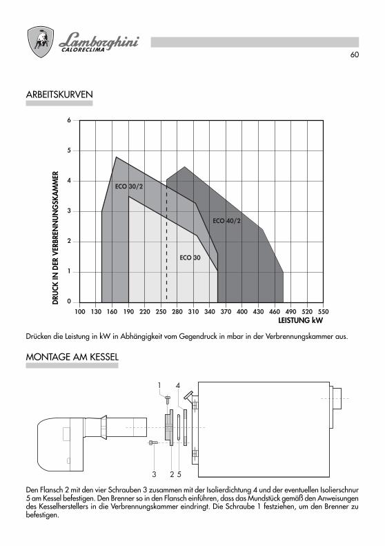
ARBEITSKURVEN
Drücken die Leistung in kW in Abhängigkeit vom Gegendruck in mbar in der Verbrennungskammer aus.
MONTAGE AM KESSEL
Den Flansch 2 mit den vier Schrauben 3 zusammen mit der Isolierdichtung 4 und der eventuellen Isolierschnur5 am Kessel befestigen. Den Brenner so in den Flansch einführen, dass das Mundstück gemäß den Anweisungendes Kesselherstellers in die Verbrennungskammer eindringt. Die Schraube 1 festziehen, um den Brenner zubefestigen.
1 4
3 2 5
DRU
CK IN
DER
VER
BREN
NU
NG
SKA
MM
ER
LEISTUNG kW

61
ELEKTROANSCHLÜSSE
Die vom Installateur vorzunehmenden Elektroanschlüsse sind folgende:
● Versorgungslinie● Thermostatenlinie● Eventuelle Blockierungs-Anzeigelampe● Eventueller Betriebsstundenzähler● Eventueller Thermostat für die Flammenmodulierung
(das Brückenkabel abtrennen)
N.B.: Sich strikt an die Vorschrift, dass max. zwei Kabel je Klemme angeschlossen werden dürfen, halten.
Achtung:
● Den Nullleiter nicht mit der Phase vertauschen● Eine gute Erdung vornehmen● Die technischen Vorschriften und die lokalen Sicherheitsnormen einhalten
ECO 30
ZEICHENERKLÄRUNG
F SicherungFA EntstörungsfilterFCA HilfskreissicherungFR lichtelektrischer WiderstandIG HauptschalterIMA Ein-/Ausschalter
MB BrennermotorMPE Klemmenleiste LandisTC KesselthermostatTS SicherheitsthermostatTR EinschalttrafoVE Magnetventil
MPELOA 24.../LMO14...
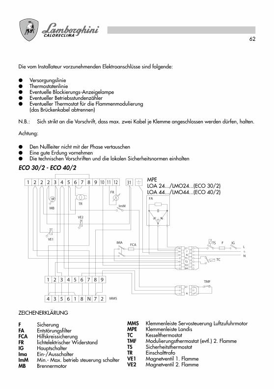
62
Die vom Installateur vorzunehmenden Elektroanschlüsse sind folgende:
● Versorgungslinie● Thermostatenlinie● Eventuelle Blockierungs-Anzeigelampe● Eventueller Betriebsstundenzähler● Eventueller Thermostat für die Flammenmodulierung
(das Brückenkabel abtrennen)
N.B.: Sich strikt an die Vorschrift, dass max. zwei Kabel je Klemme angeschlossen werden dürfen, halten.
Achtung:
● Den Nullleiter nicht mit der Phase vertauschen● Eine gute Erdung vornehmen● Die technischen Vorschriften und die lokalen Sicherheitsnormen einhalten
ECO 30/2 - ECO 40/2
1 2 2 3 4 5 6 7 8 10 11 129
M
MB
VE1
TC
TS F IG
B4
T2T1N
L1
S3
L
N
FR
2
IMA
3 5 6 1 8 N4 7 MMS
VE2
TR
FA
FCA
2 3 4 5 6 71 8 9
2N
ImM
TMF
31
L1
ZEICHENERKLÄRUNG
F SicherungFA EntstörungsfilterFCA HilfskreissicherungFR lichtelektrischer WiderstandIG HauptschalterIma Ein-/AusschalterImM Min.- Max. betrieb steuerung schalterMB Brennermotor
MMS Klemmenleiste Servosteuerung LuftzufuhrmotorMPE Klemmenleiste LandisTC KesselthermostatTMF Modulierungsthermostat (evtl.) 2. FlammeTS SicherheitsthermostatTR EinschalttrafoVE1 Magnetventil 1. FlammeVE2 Magnetventil 2. Flamme
MPELOA 24.../LMO24...(ECO 30/2)LOA 44.../LMO44...(ECO 40/2)

63
GASÖLZUFÜHRUNG
Die Auslegung der Leitungen (Durchmesser/Länge) ist in Abhängigkeit vom Anlagentyp (mit einer/zweiLeitungen, Ansaugungs-/Fallzuführung) und von den Eigenschaften der Pumpe zu bewerkstelligen.Im Diagramm ist die max. zulässige Länge L einer Ansaugleitung in Abhängigkeit vom Höhenunterschied Hund dem internen Leitungsdurchmesser d bei einem Luftdruck von 101,3 mbar und einem Vakuum von 0,45bar bei Einbau von 4 Kniestücken, eines Absperrventils und eines Rückschlagventils dargestellt.
ZUFÜHRUNG ÜBER EINE LEITUNG
Der Hersteller empfiehlt diese Lösung möglichst zu vermeiden, da sie bei nicht absolut perfekter Auslegung zubeträchtlichen Betriebsstörungen des Brenners führen kann. Ist es jedoch nicht möglich, diese Auslegung zuvermeiden, sind nur Fallanlagen zu installieren; die Pumpe ist durch Entfernen des internen Stifts abzuändern;an den höchsten Stellen der Leitungen sind geeignete Entlüftungen vorzusehen und die Bildung vonLufteinschlüssen zu verhindern.
ZUFÜHRUNG ÜBER ZWEI LEITUNGEN
N.B.: Ist die Leitung länger als 60 m, ist es ratsam, eine Förderpumpe d 10/2, d12/2 für Brenner mit zweiFlammen zu installieren.
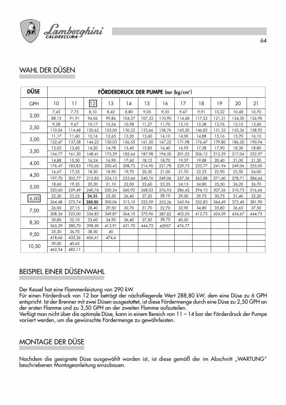
64
PRESSIONE POMPA bar (kg/cm2 )UGELLO
GPH
2,00
2,50
3,00
3,50
4,00
4,50
5,00
6,00
7,00
8,30
9,50
10,50
10 11 12 13 14 15 16 17 18 19 20 21
7,43 7,75 8,10 8,42 8,80 9,05 9,35 9,67 9,91 10,22 10,48 10,70
88,12 91,91 96,06 99,86 104,37 107,33 110,90 114,68 117,53 121,21 124,30 126,909,28 9,67 10,17 10,54 10,98 11,27 11,70 12,10 12,38 12,76 13,10 13,40
110,06 114,68 120,62 125,00 130,22 133,66 138,76 143,50 146,82 151,33 155,36 158,9211,17 11,60 12,16 12,65 13,20 13,60 14,10 14,50 14,88 15,16 15,70 16,10
132,47 137,58 144,22 150,03 156,55 161,30 167,22 171,98 176,47 179,80 186,20 190,9413,05 13,60 14,20 14,78 15,40 15,85 16,40 16,95 17,38 17,90 18,30 18,80
154,77 161,30 168,41 175,29 182,64 187,98 194,50 201,03 206,12 212,29 217,04 222,97
14,88 15,50 16,24 16,90 17,60 18,12 18,70 19,37 19,88 20,40 21,00 21,50176,47 183,83 192,60 200,43 208,73 214,90 221,78 229,73 235,77 241,94 249,06 255,0016,67 17,35 18,20 18,90 19,70 20,30 21,00 21,70 22,25 22,90 23,50 24,00
197,70 205,77 215,85 224,15 233,64 240,76 249,06 257,36 263,88 271,60 278,71 284,6418,60 19,35 20,30 21,10 22,00 22,60 23,35 24,15 24,80 25,50 26,20 26,70
220,60 229,49 240,76 250,24 260,92 268,03 286,42 294,13 307,36 310,73 316,6622,30 23,25 24,35 25,30 26,40 27,20
276,9329,00 29,75 30,75 31,40 32,20
264,48 275,74 288,80 300,06 313,10 322,59
28,10
343,94 352,83 364,49 372,40 381,9026,00 27,15 28,40 29,50 30,70 31,70
333,2633,90 34,80 35,80 36,65 37,50
308,36 322,00 336,82 349,87 364,10 375,9632,70
402,05 412,73 424,59 434,67 444,7530,80 32,10 33,60 34,90 36,40 37,50
387,8240,20
365,29 380,70 398,50 413,91 431,70 444,75
38,75
476,7735,30 36,70 38,50 40
45957
418,66 435,26 456,61 474,439,00 40,65
462,54 482,11
WAHL DER DÜSEN
BEISPIEL EINER DÜSENWAHL
MONTAGE DER DÜSE
Der Kessel hat eine Flammenleistung von 290 kW.Für einen Förderdruck von 12 bar beträgt der nächstliegende Wert 288,80 kW, dem eine Düse zu 6 GPHentspricht. Ist der Brenner mit zwei Düsen ausgestattet, ist diese Fördermenge durch eine Düse zu 2,50 GPH ander ersten Flamme und zu 3,50 GPH an der zweiten Flamme aufzuteilen.Verfügt man nicht über die optimale Düse, kann in einem Bereich von 11 – 14 bar der Förderdruck der Pumpevariiert werden, um die gewünschte Fördermenge zu gewährleisten.
Nachdem die geeignete Düse ausgewählt worden ist, ist diese gemäß der im Abschnitt „WARTUNG“beschriebenen Montageanleitung einzubauen.
DÜSE FÖRDERDRUCK DER PUMPE

65
AUSRICHTEN DER ELEKTRODEN – ABWEISER
Nach dem Einbau der Düse/n ist die korrekte Ausrichtung der Elektroden und des Abweisers anhand dernachstehend aufgeführten Angaben in mm zu prüfen. Nach jedem Eingriff am Brennerkopf ist es ratsam, eineKontrolle der Abstände vorzunehmen.
ECO 30 ECO 30/2 - ECO 40/2
BETRIEB
A StartbeginnB Anwesenheit der FlammeC StartendeC-D NormalbetriebD Einstellstop (TA-TC)
T1 Vorbelüftungszeit 13 Sek. 15 Sek.T2 Sicherheitszeit 10 Sek. 10 Sek.T3 Voreinschaltzeit 13 Sek. 15 Sek.T3n Nacheinschaltzeit 15 Sek. 10 Sek.
ECO 30
Raum-/Kesselthermostat
Motor
Trafo
Magnetventil
lichtelektrischer Widerstand
LOA 24 LMO 14

66
A StartbeginnB Anwesenheit der FlammeC StartendeC-D NormalbetriebD Einstellstop (TA-TC)
T1 Vorbelüftungszeit 13 Sek. 15 Sek.T2 Sicherheitszeit 10 Sek. 10 Sek.T3 Voreinschaltzeit 13 Sek. 15 Sek.T3n Nacheinschaltzeit 15 Sek. 10 Sek.
ECO 30/2
Raum-/Kesselthermostat
Motor
Trafo
Magnetventil 1. Flamme
lichtelektrischer Widerstand
Modulierungsthermostat
Luft-Servosteuerung
Magnetventil 2. Flamme
1.
2.
LOA 24 LMO 24
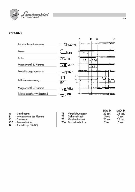
67
ECO 40/2
Raum-/Kesselthermostat
Motor
Trafo
Magnetventil 1. Flamme
lichtelektrischer Widerstand
Modulierungsthermostat
Luft-Servosteuerung
Magnetventil 2. Flamme
1.
2.
A - StartbeginnB - Anwesenheit der FlammeC - StartendeC-D - NormalbetriebD - Einstellstop (TA-TC)
LOA 44 LMO 44T1 Vorbelüftungszeit 25 sec. 26 sec.T2 Sicherheitszeit 5 sec. 5 sec.T3 Voreinschaltzeit 25 sec. 25 sec.T3n Nacheinschaltzeit 2 sec. 5 sec.

68
LMO-GERÄT
Die Freigabetaste des Gerätes ist das wichtigste Element, um, außer die Steuer- und Kontrollvorrichtungfreizugeben, an alle Diagnosefunktionen (ein- und ausschalten) gelangen zu können.Die Freigabetaste ist mit einem mehrfarbigen LED ausgestattet, das die Funktion einer Statusanzeige für dieSteuer- und Kontrollvorrichtung, sowohl bei Betrieb, als in Diagnosefunktion hat.
ANZEIGE DES GERÄTEZUSTANDSZusammenfassende Tabelle
Zustand Farb-Abfolge
Wartezustand, andere Übergangszustände Kein LichtBrennstoff-Vorheizung "Ein", Wartezeit max. 5 Sek. Gelb
Anheizphase Gelb blinkendRichtiger Betrieb GrünFalscher Betrieb, Stromstärke Flammwächter unterzulässigem Mindestwert
Grün blinkend
Abfall der Versorgungsspannung Abwechselnd Gelb RotBlockierungszustand Brenner Rot
Störungsanzeige (siehe Tabelle auf Seite 8) Rot blinkendStreulicht vorm Anheizen des Brenners Abwechselnd Grün Rot
Schnelles Blinken für Diagnostik Rot schnell blinkend
Bei blockiertem Brenner ist das rote Licht in der Freigabetaste ständig eingeschaltet.Wir die durchsichtige Taste gedrückt, wird die Steuer- und Kontrollvorrichtung freigegeben.Wird länger als 3 Sekunden gedrückt, wird die Diagnosephase eingeschaltet (das rote Licht blinkt schnell). Inder nachstehenden Tabelle wird die Ursache der Blockierung oder der Störung abhängig von der Blink-Anzahl(immer rotes Licht) angegeben.Wird die Freigabetaste länger als 3 Sek. Gedrückt, wird die Diagnosefunktion ausgeschaltet.
DIAGNOSE DER URSACHEN FÜR STÖRUNGEN UND BLOCKIERUNG DES LMO-GERÄTSZusammenfassung Betriebsstörungen
Optische Anzeige Mögliche Ursache
2-maliges Blinken Ausfall des Flamm-Signals- Störung an den Brennstoffventilen- Störung am Flammwächter- Falsche Einstellung des Brenners, Brennstoffmangel- Anheizphase ausgefallen
3-maliges Blinken Frei
4-maliges Blinken Streulicht beim Anheizen
5-maliges Blinken Frei
6-maliges Blinken Frei
7-maliges Blinken Ausfall des Flamm-Signals während des Betriebs- Störung an den Brennstoffventilen- Störung am Flammwächter- Falsche Einstellung des Brenners, Brennstoffmangel
8-maliges Blinken Störung bei der Brennstoff-Vorheizdauer
9-maliges Blinken Frei
10-maliges Blinken Fehler an elektrischen Anschlüssen oder Schäden am Gerät
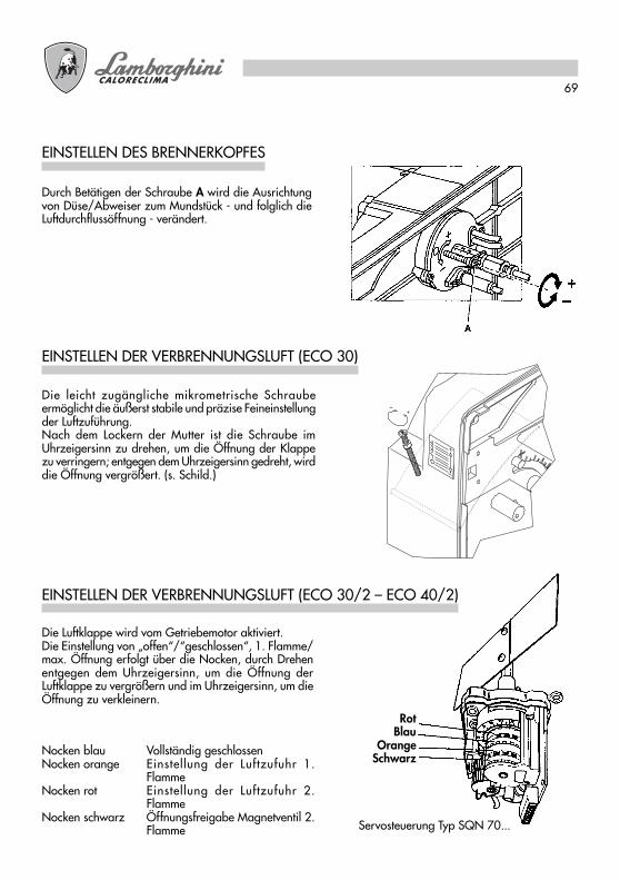
69
EINSTELLEN DER VERBRENNUNGSLUFT (ECO 30)
Die leicht zugängliche mikrometrische Schraubeermöglicht die äußerst stabile und präzise Feineinstellungder Luftzuführung.Nach dem Lockern der Mutter ist die Schraube imUhrzeigersinn zu drehen, um die Öffnung der Klappezu verringern; entgegen dem Uhrzeigersinn gedreht, wirddie Öffnung vergrößert. (s. Schild.)
EINSTELLEN DES BRENNERKOPFES
Durch Betätigen der Schraube A wird die Ausrichtungvon Düse/Abweiser zum Mundstück - und folglich dieLuftdurchflussöffnung - verändert.
Die Luftklappe wird vom Getriebemotor aktiviert.Die Einstellung von „offen“/“geschlossen“, 1. Flamme/max. Öffnung erfolgt über die Nocken, durch Drehenentgegen dem Uhrzeigersinn, um die Öffnung derLuftklappe zu vergrößern und im Uhrzeigersinn, um dieÖffnung zu verkleinern.
EINSTELLEN DER VERBRENNUNGSLUFT (ECO 30/2 – ECO 40/2)
Nocken blau Vollständig geschlossenNocken orange Einstellung der Luftzufuhr 1.
FlammeNocken rot Einstellung der Luftzufuhr 2.
FlammeNocken schwarz Öffnungsfreigabe Magnetventil 2.
Flamme Servosteuerung Typ SQN 70...
RotBlau
OrangeSchwarz
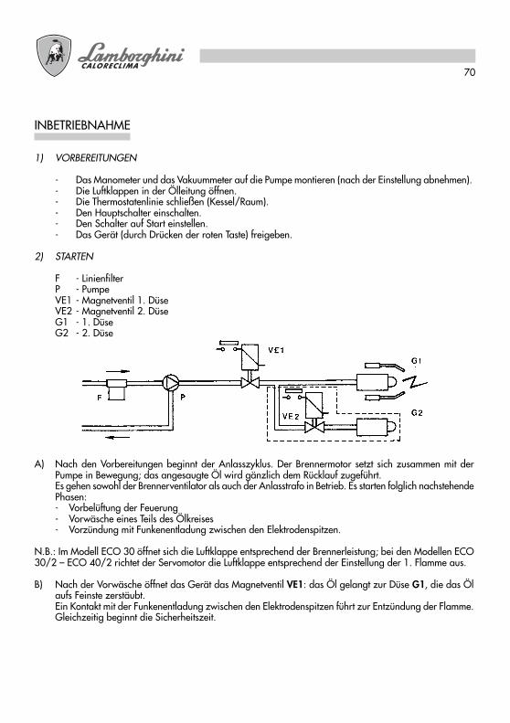
70
INBETRIEBNAHME
1) VORBEREITUNGEN
- Das Manometer und das Vakuummeter auf die Pumpe montieren (nach der Einstellung abnehmen).- Die Luftklappen in der Ölleitung öffnen.- Die Thermostatenlinie schließen (Kessel/Raum).- Den Hauptschalter einschalten.- Den Schalter auf Start einstellen.- Das Gerät (durch Drücken der roten Taste) freigeben.
2) STARTEN
F - LinienfilterP - PumpeVE1 - Magnetventil 1. DüseVE2 - Magnetventil 2. DüseG1 - 1. DüseG2 - 2. Düse
A) Nach den Vorbereitungen beginnt der Anlasszyklus. Der Brennermotor setzt sich zusammen mit derPumpe in Bewegung; das angesaugte Öl wird gänzlich dem Rücklauf zugeführt.Es gehen sowohl der Brennerventilator als auch der Anlasstrafo in Betrieb. Es starten folglich nachstehendePhasen:- Vorbelüftung der Feuerung- Vorwäsche eines Teils des Ölkreises- Vorzündung mit Funkenentladung zwischen den Elektrodenspitzen.
N.B.: Im Modell ECO 30 öffnet sich die Luftklappe entsprechend der Brennerleistung; bei den Modellen ECO30/2 – ECO 40/2 richtet der Servomotor die Luftklappe entsprechend der Einstellung der 1. Flamme aus.
B) Nach der Vorwäsche öffnet das Gerät das Magnetventil VE1: das Öl gelangt zur Düse G1, die das Ölaufs Feinste zerstäubt.Ein Kontakt mit der Funkenentladung zwischen den Elektrodenspitzen führt zur Entzündung der Flamme.Gleichzeitig beginnt die Sicherheitszeit.
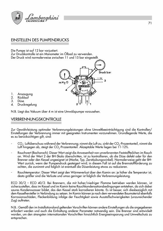
71
Die Pumpe ist auf 12 bar vorjustiert.Zur Druckkontrolle ist ein Manometer im Ölbad zu verwenden.Der Druck wird normalerweise zwischen 11 und 15 bar eingestellt.
EINSTELLEN DES PUMPENDRUCKS
1. Ansaugung2. Rücklauf3. Düse4. Druckregelung
N.B. Liegt das Vakuum über 4 m ist eine Umwälzpumpe vorzusehen.
Zur Gewährleistung optimaler Verbrennungsleistungen ohne Umweltbeeinträchtigung sind die Kontrollen/Einstellungen der Verbrennung immer mit geeigneten Instrumenten vorzunehmen. Grundlegende Werte, diees zu berücksichtigen gilt, sind:
- CO2: Luftüberschuss während der Verbrennung; nimmt die Luft zu, sinkt der CO2-Prozentanteil, nimmt dieLuft hingegen ab, steigt der CO2-Prozentanteil. Akzeptable Werte liegen bei 11-12%.
- Rauchwert (Bacharach): Dieser Wert zeigt die Anwesenheit von unverbrannten Feststoffteilchen im Rauchan. Wird der Wert 2 der BH-Skala überschritten, ist zu kontrollieren, ob die Düse defekt oder für denBrenner oder den Kessel ungeeignet ist (Marke, Typ, Zerstäubungswinkel). Normalerweise geht der BH-Wert zurück, wenn der Pumpendruck gesteigert wird; in diesem Fall ist auf die Brennstoffförderung zuachten, die zunimmt und folglich ist eventuell die Düsenleistung etwas zu reduzieren.
- Rauchtemperatur: Dieser Wert zeigt den Wärmeverlust über den Kamin an: je höher die Temperatur ist,desto größer sind die Verluste und umso geringer ist folglich die Verbrennungsleistung.
ECO 30/2 – ECO 40/2. Bei Brennern, die mit hoher/niedriger Flamme betrieben werden können, istsicherzustellen, dass im Kessel und im Kamin keine Rauchkondensationsbedingungen entstehen, da sich dabeisaures Kondenswasser bildet, das den Kessel stark korrodieren könnte. Es ist besser, sich diesbezüglich mitdem Kesselhersteller in Verbindung zu setzen. Im Kamin können je nach dem verwendeten Baumaterial ebenfallsKorrosionsschäden, Fleckenbildung infolge der Feuchtigkeit sowie Ausstoßschwierigkeiten (unzureichenderZug) auftreten.
N.B.: Gemäß den im Installationsland geltenden Vorschriften können andere Einstellungen als die angegebenenerfordert werden und auch die Einhaltung anderer Parameter notwendig sein. Die Brenner sind entwickeltworden, um den strengsten internationalen Vorschriften hinsichtlich Energieeinsparung und Umweltschutz zuentsprechen.
VERBRENNUNGSKONTROLLE
Druck

72
Alle Wartungsarbeiten dürfen ausnahmslos nur nach Unterbrechung der Stromversorgung durchgeführt werden.Nach dem Entfernen der Abdeckung können der lichtelektrische Widerstand gereinigt und der Motor, dasMagnetventil, der Transformator und der Servomotor der Luftklappe inspiziert werden. Um Zugang zumFlügelrad und zur Luftklappe zu erhalten, ist die Gruppe Platte / Komponententräger herauszuziehen und inder vorgesehenen Wartungsstellung einzuhaken; dadurch wird auch der Brennerkopf vollständig zugänglich.Zum Reinigen/Inspizieren der Düsen – Elektroden wird normalerweise der Brennerkopf durch Entfernen deroberen Platte herausgenommen.
WARTUNG
Aus seinem Sitz ausbauen und seinen empfindlichen Teil mit einem trockenen Tuch reinigen.
LICHTELEKTRISCHER WIDERSTAND
Den Schieber an der Ansaugung schließen, den Pumpendeckel ausbauen, den Netzeinsatz herausnehmenund mit Benzin reinigen und mit Gasöl spülen. Sorgfältig wieder einbauen.
PUMPENFILTER
Den Schieber an der Ansaugung schließen, den normalerweise auf dem Filterkörper aufgeschraubten Filterkorbausbauen und das Filternetz sorgfältig reinigen. Alles wieder vorsichtig einbauen.
LINIENFILTER
Um Zugang zu den Hauptkomponenten zu erhalten, genügt es, die Haube abzunehmen.Die Wartung des Brennerkopfs ist folgendermaßen durchzuführen:● Die Schrauben entfernen und die Haube abnehmen.● Die Schrauben der oberen Platte entfernen und sie in Wartungsstellung einhaken.● Um das Flügelrad zu erreichen sind die Schrauben der unteren Platte zu entfernen und die Anschlüsse
der elektrischen Schalttafel abzutrennen.
LUFTKLAPPEN-FLÜGELRAD
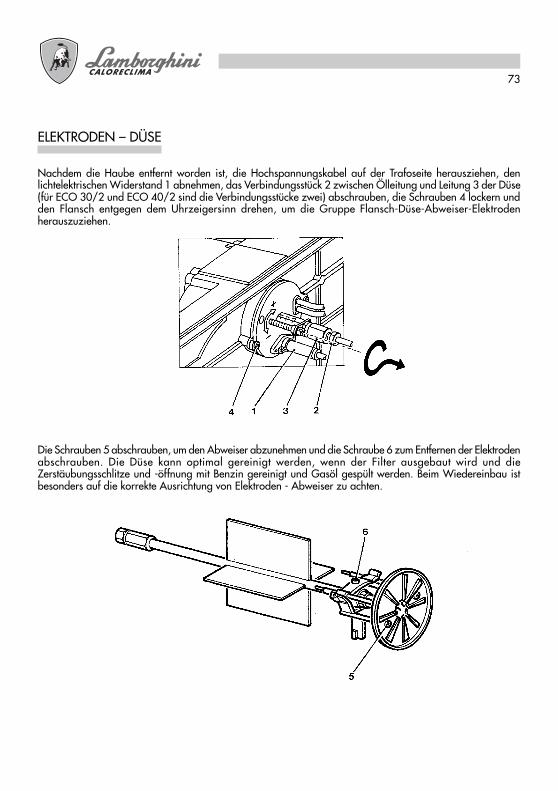
73
Nachdem die Haube entfernt worden ist, die Hochspannungskabel auf der Trafoseite herausziehen, denlichtelektrischen Widerstand 1 abnehmen, das Verbindungsstück 2 zwischen Ölleitung und Leitung 3 der Düse(für ECO 30/2 und ECO 40/2 sind die Verbindungsstücke zwei) abschrauben, die Schrauben 4 lockern undden Flansch entgegen dem Uhrzeigersinn drehen, um die Gruppe Flansch-Düse-Abweiser-Elektrodenherauszuziehen.
Die Schrauben 5 abschrauben, um den Abweiser abzunehmen und die Schraube 6 zum Entfernen der Elektrodenabschrauben. Die Düse kann optimal gereinigt werden, wenn der Filter ausgebaut wird und dieZerstäubungsschlitze und -öffnung mit Benzin gereinigt und Gasöl gespült werden. Beim Wiedereinbau istbesonders auf die korrekte Ausrichtung von Elektroden - Abweiser zu achten.
ELEKTRODEN – DÜSE
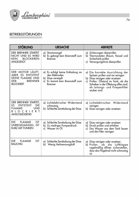
74
BETRIEBSSTÖRUNGEN
ABHILFEURSACHESTÖRUNGa) Strommangelb) Es gelangt kein Brennstoff zum
Brenner
a) Es erfolgt keine Entladung anden Elektroden
b) Düse verstopftc) Es kommt kein Brennstoff zum
Brenner
a) Lichtelektrischer Widerstandschmutzig
b) Schlechte Zerstäubung der Düse.
a) Schlechte Zerstäubung der Düse.b) Zu niedriger Pumpendruckc) Wasser im Öl
a) Schlechte Zerstäubung der Düse.b) Wenig Verbrennungsluft
a) Sicherungen überprüfenb) Thermostaten (Raum, Kessel und
Sicherheit) prüfenc) Versorgungslinie überprüfen
a) Die korrekte Ausrichtung derSpitzen prüfen und sie reinigen
b) Düse reinigen oder ersetzenc) Prüfen: Ölstand im Tank; ob die
Schieber in der Ölleitung offen sind;ob Leitungs- und Pumpenfiltersauber sind.
a) Lichtelektrischen Widerstandreinigen
b) Düse reinigen oder ersetzen
a) Düse reinigen oder ersetzenb) Druck prüfen und erhöhenc) Das Wasser aus dem Tank lassen
und die Filter reinigen
a) Düse reinigen oder ersetzenb) Prüfen, ob die Luftklappe
regelmäßig öffnet; sicherstellen,dass das Flügelrad nicht schmutzigist.
DER BRENNER STARTETNICHT UND ES WIRDKEIN BLOCKIERENANGEZEIGT
DER MOTOR LÄUFT,ABER ES ENTSTEHTKEINE FLAMME UNDDER BRENNERBLOCKIERT
DER BRENNER STARTET,ES ENTSTEHT DIEFLAMME UNDB L O C K I E R TANSCHLIESSEND
DIE FLAMME ISTUNREGELMÄSSIG, ISTKURZ MIT FUNKEN
DIE FLAMME ISTRAUCHIG
Leer detenidamente las instrucciones y advertencias contenidas en el presente manual porcuanto ofrecen importantes indicaciones que se refieren a la seguridad de instalación, deuso y de mantenimiento. Tratar este manual con delicadeza y conservarlo en un lugarseguro para poder consultarlo cada vez que sea necesario. La instalación deberá serrealizada p or personal capacitado y calificado, que tendrá asimismo la responsabilidadde respetar la normativa vigente sobre seguridad.
ES

76
j Enhorabuena …...Por la óptima elección. Le agradecemos por la preferencia que ha demostrado hacia nuestros
productos. LAMBORGHINI CALORECLIMA está, presente activamente desde 1959 en Italia y en el mundocon una red capilar de Agentes y Concesionarios, que garantizan constantemente la presencia del productoen el mercado.A todo ello se une un servicio de asistencia técnica, «LAMBORGHINI SERVICE», cualificado en elmantenimiento del producto.
ÍNDICE PÁGINA
DATOS TÉCNICOS _______________________________ 77DIMENSIONES __________________________________ 77CURVAS DE TRABAJO ____________________________ 78MONTAJE EN LA CALDERA________________________ 78CONEXIONES ELÉCTRICAS ________________________ 79ALIMENTACIÓN GASÓLEO _______________________ 81ALIMENTACIÓN MONOTUBO _____________________ 81ALIMENTACIÓN BITUBO __________________________ 81ELECCIÓN DEL INYECTOR _________________________ 82EJEMPLO ELECCIÓN INYECTOR ____________________ 82MONTAJE INYECTOR _____________________________ 82POSICIÓN ELECTRODOS-DEFLECTOR _______________ 83CICLO DE FUNCIONAMIENTO _____________________ 83EQUIPO LMO ___________________________________ 86REGULACIÓN DE LA CABEZA _____________________ 87REGULACIÓN AIRE DE COMBUSTIÓN (ECO 30)______ 87REGULACIÓN AIRE DE COMBUSTIÓN (ECO 30/2 - ECO 40/2) _87PUESTA EN FUNCIÓN ____________________________ 88REGULACIÓN PRESIÓN BOMBA ___________________ 89CONTROL DE COMBUSTIÓN ______________________ 89MANTENIMIENTO _______________________________ 90FOTO RESISTENCIA ______________________________ 90FILTRO DE BOMBA _______________________________ 90FILTRO DE LÍNEA _________________________________ 90VENTILADOR TAPA AIRE __________________________ 90ELECTRODOS INYECTOR __________________________ 91IRREGULARIDADES DE FUNCIONAMIENTO __________ 92
Para la instalación y el posicionamiento de la caldera:RESPETAR ESCRUPULOSAMENTE LAS NORMAS VIGENTES LOCALES.
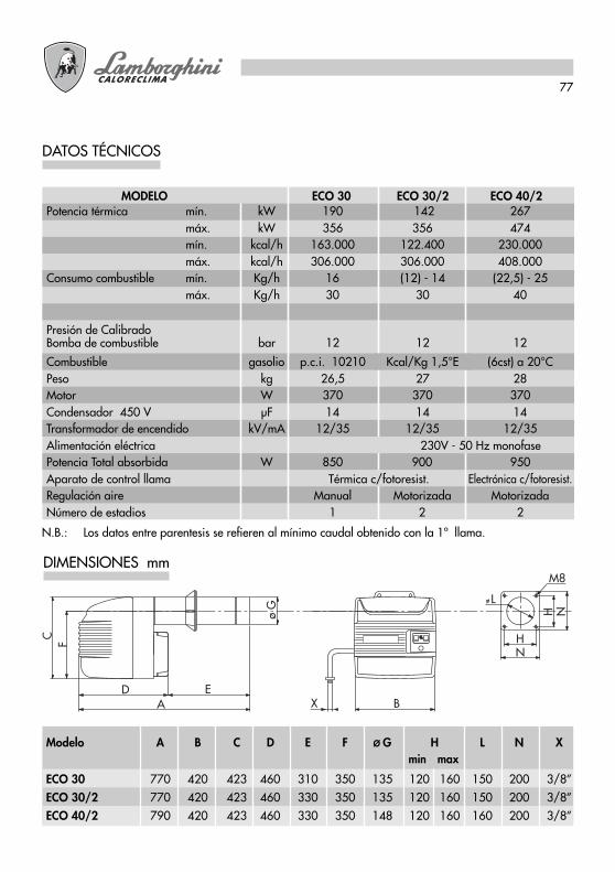
77
DATOS TÉCNICOS
N.B.: Los datos entre parentesis se refieren al mínimo caudal obtenido con la 1ª llama.
DIMENSIONES mm
X
F H
L
M8
N
A B
C
ED
H Nø G
min maxModelo A B C D E F Ø G H L N X
ECO 30 770 420 423 460 310 350 135 120 160 150 200 3/8”ECO 30/2 770 420 423 460 330 350 135 120 160 150 200 3/8”ECO 40/2 790 420 423 460 330 350 148 120 160 160 200 3/8”
MODELO ECO 30 ECO 30/2 ECO 40/2Potencia térmica mín. kW 190 142 267
máx. kW 356 356 474mín. kcal/h 163.000 122.400 230.000máx. kcal/h 306.000 306.000 408.000
Consumo combustible mín. Kg/h 16 (12) - 14 (22,5) - 25máx. Kg/h 30 30 40
Presión de CalibradoBomba de combustible bar 12 12 12
Combustible gasolio p.c.i. 10210 Kcal/Kg 1,5°E (6cst) a 20°CPeso kg 26,5 27 28Motor W 370 370 370Condensador 450 V µF 14 14 14Transformador de encendido kV/mA 12/35 12/35 12/35Alimentación eléctrica 230V - 50 Hz monofasePotencia Total absorbida W 850 900 950Aparato de control llama Térmica c/fotoresist. Electrónica c/fotoresist.Regulación aire Manual Motorizada MotorizadaNúmero de estadios 1 2 2

78
CURVAS DE TRABAJO
Indican la potencia en kw, en función de la contrapresión, en mbar, en la cámara de combustión.
MONTAJE EN LA CALDERA
Fijar la brida (2) a la caldera con n° 4 tornillos (3) interponiendo la guarnición aislante (4) y la eventualcuerda aislante (5). Introducir el quemador a la brida de modo que la tobera penetre en la cámara decombustión según las indicaciones del fabricante de la caldera. Ajustar el tornillo 1 para bloquear el quemador.
1 4
3 2 5
ECO 30
100 130 160 190 220 250 280 310 340 370 400 430 460 490 520 550POTENZA kW
6
4
3
2
1
0PRES
SIO
NE
IN C
AM
ERA
DI C
OM
BUST
ION
E m
bar
ECO 40/2
5
ECO 30/2
POTENCIA kW
PRES
IÓN
EN
LA C
ÁMAR
A DE
CO
MBU
STIÓ
N M
BAR
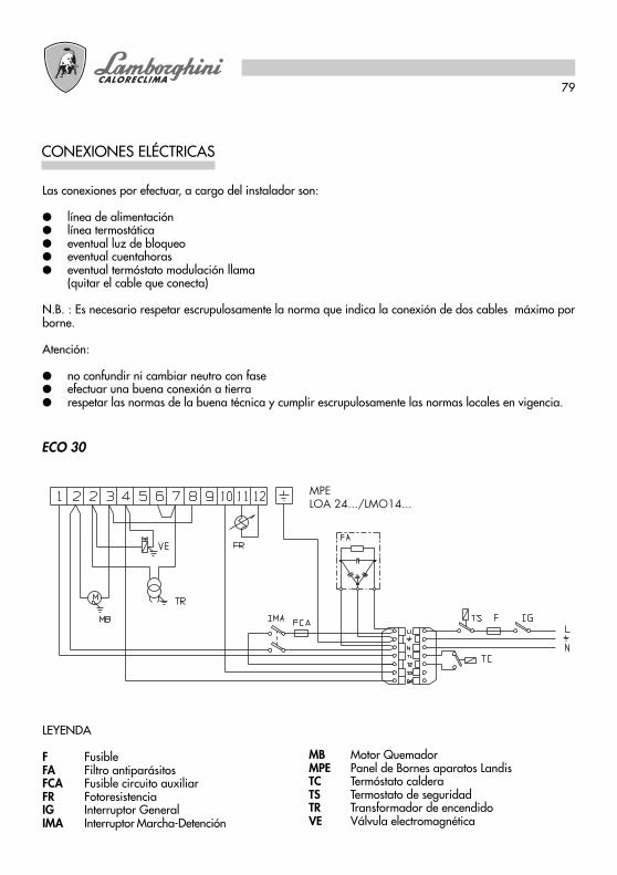
79
CONEXIONES ELÉCTRICAS
Las conexiones por efectuar, a cargo del instalador son:
● línea de alimentación● línea termostática● eventual luz de bloqueo● eventual cuentahoras● eventual termóstato modulación llama
(quitar el cable que conecta)
N.B. : Es necesario respetar escrupulosamente la norma que indica la conexión de dos cables máximo porborne.
Atención:
● no confundir ni cambiar neutro con fase● efectuar una buena conexión a tierra● respetar las normas de la buena técnica y cumplir escrupulosamente las normas locales en vigencia.
ECO 30
MPELOA 24.../LMO14...
LEYENDA
F FusibleFA Filtro antiparásitosFCA Fusible circuito auxiliarFR FotoresistenciaIG Interruptor GeneralIMA Interruptor Marcha-Detención
MB Motor QuemadorMPE Panel de Bornes aparatos LandisTC Termóstato calderaTS Termostato de seguridadTR Transformador de encendidoVE Válvula electromagnética
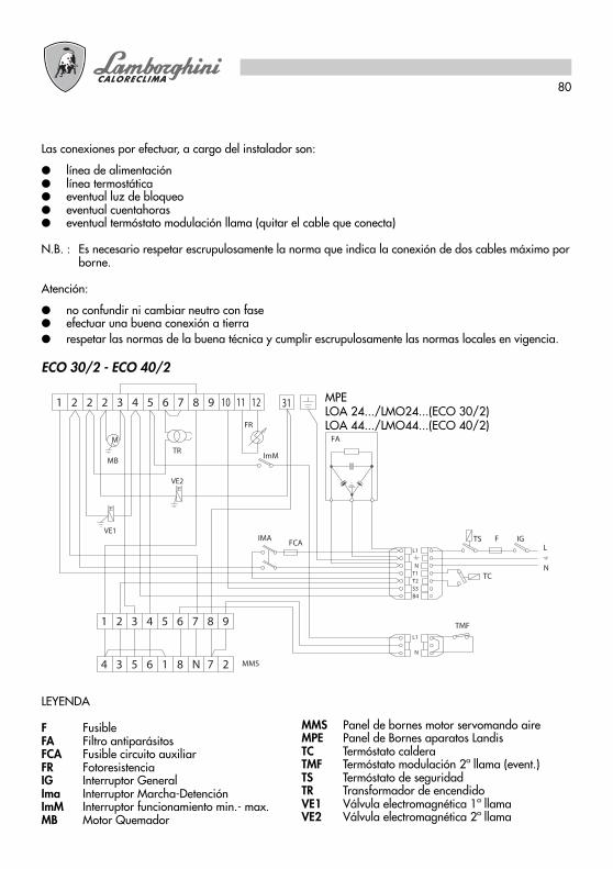
80
Las conexiones por efectuar, a cargo del instalador son:
● línea de alimentación● línea termostática● eventual luz de bloqueo● eventual cuentahoras● eventual termóstato modulación llama (quitar el cable que conecta)
N.B. : Es necesario respetar escrupulosamente la norma que indica la conexión de dos cables máximo porborne.
Atención:
● no confundir ni cambiar neutro con fase● efectuar una buena conexión a tierra
ECO 30/2 - ECO 40/2
1 2 2 3 4 5 6 7 8 10 11 129
M
MB
VE1
TC
TS F IG
B4
T2T1N
L1
S3
L
N
FR
2
IMA
3 5 6 1 8 N4 7 MMS
VE2
TR
FA
FCA
2 3 4 5 6 71 8 9
2N
ImM
TMF
31
L1
LEYENDA
F FusibleFA Filtro antiparásitosFCA Fusible circuito auxiliarFR FotoresistenciaIG Interruptor GeneralIma Interruptor Marcha-DetenciónImM Interruptor funcionamiento min.- max.MB Motor Quemador
MMS Panel de bornes motor servomando aireMPE Panel de Bornes aparatos LandisTC Termóstato calderaTMF Termóstato modulación 2ª llama (event.)TS Termóstato de seguridadTR Transformador de encendidoVE1 Válvula electromagnética 1ª llamaVE2 Válvula electromagnética 2ª llama
● respetar las normas de la buena técnica y cumplir escrupulosamente las normas locales en vigencia.
MPELOA 24.../LMO24...(ECO 30/2)LOA 44.../LMO44...(ECO 40/2)
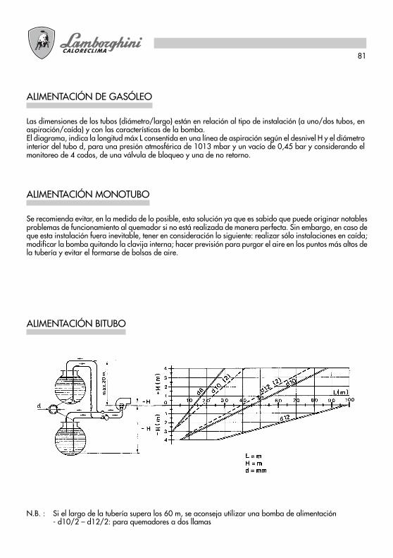
81
ALIMENTACIÓN DE GASÓLEO
Las dimensiones de los tubos (diámetro/largo) están en relación al tipo de instalación (a uno/dos tubos, enaspiración/caída) y con las características de la bomba.El diagrama, indica la longitud máx L consentida en una línea de aspiración según el desnivel H y el diámetrointerior del tubo d, para una presión atmosférica de 1013 mbar y un vacío de 0,45 bar y considerando elmonitoreo de 4 codos, de una válvula de bloqueo y una de no retorno.
ALIMENTACIÓN MONOTUBO
Se recomienda evitar, en la medida de lo posible, esta solución ya que es sabido que puede originar notablesproblemas de funcionamiento al quemador si no está realizada de manera perfecta. Sin embargo, en caso deque esta instalación fuera inevitable, tener en consideración lo siguiente: realizar sólo instalaciones en caída;modificar la bomba quitando la clavija interna; hacer previsión para purgar el aire en los puntos más altos dela tubería y evitar el formarse de bolsas de aire.
ALIMENTACIÓN BITUBO
N.B. : Si el largo de la tubería supera los 60 m, se aconseja utilizar una bomba de alimentación- d10/2 – d12/2: para quemadores a dos llamas

82
PRESSIONE POMPA bar (kg/cm2 )UGELLO
GPH
2,00
2,50
3,00
3,50
4,00
4,50
5,00
6,00
7,00
8,30
9,50
10,50
10 11 12 13 14 15 16 17 18 19 20 21
7,43 7,75 8,10 8,42 8,80 9,05 9,35 9,67 9,91 10,22 10,48 10,70
88,12 91,91 96,06 99,86 104,37 107,33 110,90 114,68 117,53 121,21 124,30 126,909,28 9,67 10,17 10,54 10,98 11,27 11,70 12,10 12,38 12,76 13,10 13,40
110,06 114,68 120,62 125,00 130,22 133,66 138,76 143,50 146,82 151,33 155,36 158,9211,17 11,60 12,16 12,65 13,20 13,60 14,10 14,50 14,88 15,16 15,70 16,10
132,47 137,58 144,22 150,03 156,55 161,30 167,22 171,98 176,47 179,80 186,20 190,9413,05 13,60 14,20 14,78 15,40 15,85 16,40 16,95 17,38 17,90 18,30 18,80
154,77 161,30 168,41 175,29 182,64 187,98 194,50 201,03 206,12 212,29 217,04 222,97
14,88 15,50 16,24 16,90 17,60 18,12 18,70 19,37 19,88 20,40 21,00 21,50176,47 183,83 192,60 200,43 208,73 214,90 221,78 229,73 235,77 241,94 249,06 255,0016,67 17,35 18,20 18,90 19,70 20,30 21,00 21,70 22,25 22,90 23,50 24,00
197,70 205,77 215,85 224,15 233,64 240,76 249,06 257,36 263,88 271,60 278,71 284,6418,60 19,35 20,30 21,10 22,00 22,60 23,35 24,15 24,80 25,50 26,20 26,70
220,60 229,49 240,76 250,24 260,92 268,03 286,42 294,13 307,36 310,73 316,6622,30 23,25 24,35 25,30 26,40 27,20
276,9329,00 29,75 30,75 31,40 32,20
264,48 275,74 288,80 300,06 313,10 322,59
28,10
343,94 352,83 364,49 372,40 381,9026,00 27,15 28,40 29,50 30,70 31,70
333,2633,90 34,80 35,80 36,65 37,50
308,36 322,00 336,82 349,87 364,10 375,9632,70
402,05 412,73 424,59 434,67 444,7530,80 32,10 33,60 34,90 36,40 37,50
387,8240,20
365,29 380,70 398,50 413,91 431,70 444,75
38,75
476,7735,30 36,70 38,50 40
45957
418,66 435,26 456,61 474,439,00 40,65
462,54 482,11
ELECCIÓN DEL INYECTOR
EJEMPLO ELECCIÓN INYECTOR
MONTAJE INYECTOR
La caldera posee una potencia de fogón de 290 kW.Para una presión en la bomba de 12 bar, el valor más próximo es kW 288,80 al que corresponde un inyectorde 6 GPH. Si el quemador es a 2 inyectores, dividir el caudal con un inyector de 2,50 GPH sobre la primerallama y de 3,50 GPH sobre la segunda.Si no se posee un inyector optimal se podrá, en límites de 11-14 bar, variar la presión de la bomba paraobtener la capacidad deseada.
Una vez escogido el inyector apto, proceder a montar como indicado en el parágrafo “MANTENIMIENTO”.
INYECTOR PRESIÓN BOMBA
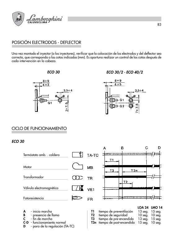
83
POSICIÓN ELECTRODOS - DEFLECTOR
Una vez montado el inyector (o los inyectores), verificar que la colocación de los electrodos y del deflector seacorrecta, que corresponda a las cotas indicadas (mm). Es oportuno realizar un control de las cotas después decada intervención en la cabeza.
ECO 30 ECO 30/2 - ECO 40/2
CICLO DE FUNCIONAMIENTO
A - inicio marcha T1 tiempo de preventilación 13 seg. 15 seg.B - presencia de llama T2 tiempo de seguridad 10 seg. 10 seg.C - fin de marcha T3 tiempo de pre-encendido 13 seg. 15 seg.C-D - funciionamiento normal T3n tiempo de post-encendido 15 seg. 10 seg.D - paro de la regulación (TA-TC)
ECO 30
Termóstato amb. . caldera
Motor
Transformador
Válvula electromagnética
Fotoresistencia
LOA 24 LMO 14

84
A - inicio marcha T1 tiempo de preventilación 13 seg. 15 seg.B - presencia de llama T2 tiempo de seguridad 10 seg. 10 seg.C - fin de marcha T3 tiempo de pre-encendido 13 seg. 15 seg.C-D - funcionamiento normal T3n tiempo de post-encendido 15 seg. 10 seg.D - paro de la regulación (TA-TC)
ECO 30/2
Termóstato amb. - caldera
Motor
Transformador
Válvula electromagnética 1° llama
Fotoresistencia
Termóstato modulación
Servomando aire
Válvula electromagnética 2ª llama
LOA 24 LMO 24
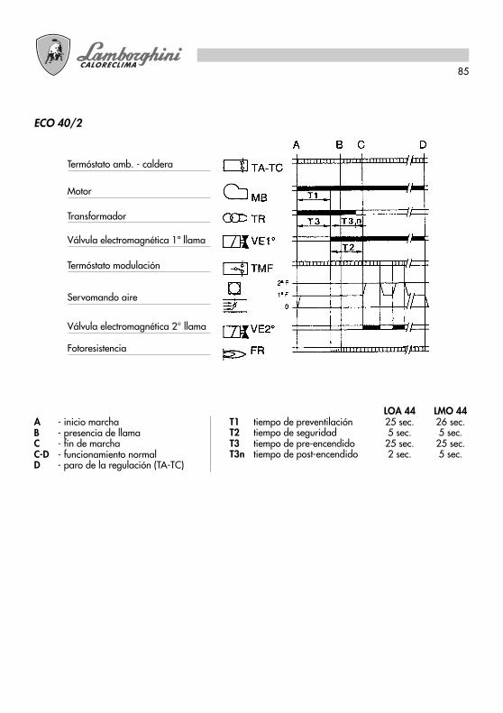
85
ECO 40/2
Termóstato amb. - caldera
Motor
Transformador
Válvula electromagnética 1ª llama
Fotoresistencia
Termóstato modulación
Servomando aire
Válvula electromagnética 2° llama
A - inicio marchaB - presencia de llamaC - fin de marchaC-D - funcionamiento normalD - paro de la regulación (TA-TC)
LOA 44 LMO 44T1 tiempo de preventilación 25 sec. 26 sec.T2 tiempo de seguridad 5 sec. 5 sec.T3 tiempo de pre-encendido 25 sec. 25 sec.T3n tiempo de post-encendido 2 sec. 5 sec.
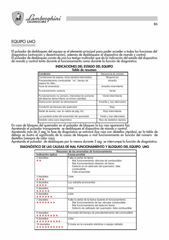
86
EQUIPO LMO
El pulsador de desbloqueo del equipo es el elemento principal para poder acceder a todas las funciones deldiagnóstico (activación y desactivación), además de desbloquear el dispositivo de mando y control.El pulsador de desbloqueo consta de una luz testigo multicolor que da la indicación del estado del dispositivode mando y control tanto durante el funcionamiento como durante la función de diagnóstico.
INDICACIONES DEL ESTADO DEL EQUIPOTabla de resumen
Condición Secuencia de colores
Condiciones de espera, otros estados intermedios Ninguna luz
Precalentamiento combustible “on”, tiempo deespera 5s. Máx.
Amarillo
Fase de encendido Amarillo intermitente
Funcionamiento correcto Verde
Funcionamiento no correcto, intensidad de corrientedel detector llama inferior al mínimo admitido
Verde intermitente
Disminución tensión de alimentación Amarillo y rojo alternados
Condición de bloqueo del quemador Rojo
Señal de avería, vea la «tabla de pág. 8») Rojo intermitente
Luz parásita antes del encendido del quemador Verde y rojo alternados
Destello veloz para diagnóstico Rojo de destellos rápidos
En caso de bloqueo del quemador en el pulsador de bloqueo la luz roja aparecerá fija.Apretando el pulsador transparente se desbloquea el dispositivo de mando y control.Apretando más de 3 seg. la fase de diagnóstico se activará (luz roja con destellos rápidos), en la tabla dedebajo se ilustra el significado de la causa de bloqueo o mal funcionamiento en función del número dedestellos (siempre de color rojo).Apretando el pulsador de desbloqueo por lo menos durante 3 seg. se interrumpe la función de diagnóstico.
DIAGNÓSTICO DE LAS CAUSAS DE MAL FUNCIONAMIENTO Y BLOQUEO DEL EQUIPO LMOResumen de las anomalías de funcionamiento
Indicación óptica Causa posible
2 destellos � �
Falta la señal de llama- Mal funcionamiento válvulas de combustible- Mal funcionamiento detector de llama- Defecto en el calibrado del quemador, falta
combustible- Falta encendido
3 destellos � � �
Libre
4 destellos � � � �
Luz extraña al encender
5 destellos � � � � �
Libre
6 destellos � � � � � �
Libre
7 destellos � � � � � � �
Falta la señal de la llama durante el funcionamiento- Mal funcionamiento de las válvulas combustible- Mal funcionamiento del detector llama- Defecto de calibrado del quemador, falta combustible
8 destellos � � � � � � � �
Anomalía del tiempo de precalentamiento del combustible
9 destellos � � � � � � � � �
Libre
10 destellos � � � � � � � � � �
Errores en la conexión eléctrica o equipo dañado
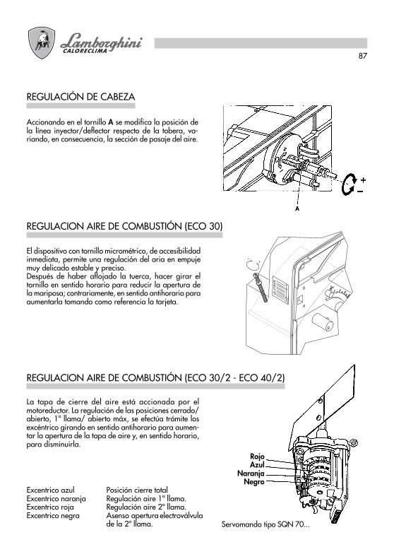
87
REGULACION AIRE DE COMBUSTIÓN (ECO 30)
El dispositivo con tornillo micrométrico, de accesibilidadinmediata, permite una regulación del aria en empujemuy delicado estable y preciso.Después de haber aflojado la tuerca, hacer girar eltornillo en sentido horario para reducir la apertura dela mariposa; contrariamente, en sentido antihorario paraaumentarla tomando como referencia la tarjeta.
REGULACIÓN DE CABEZA
Accionando en el tornillo A se modifica la posición dela línea inyector/deflector respecto de la tobera, va-riando, en consecuencia, la sección de pasaje del aire.
La tapa de cierre del aire está accionada por elmotoreductor. La regulación de las posiciones cerrado/abierto, 1ª llama/ abierto máx, se efectúa trámite losexcéntrico girando en sentido antihorario para aumen-tar la apertura de la tapa de aire y, en sentido horario,para disminuirla.
REGULACION AIRE DE COMBUSTIÓN (ECO 30/2 - ECO 40/2)
Excentrico azul Posición cierre totalExcentrico naranja Regulación aire 1ª llama.Excentrico roja Regulación aire 2ª llama.Excentrico negra Asenso apertura electroválvula
de la 2ª llama. Servomando tipo SQN 70...
RojoAzul
NaranjaNegro

88
PUESTA EN FUNCIÓN
1) OPERACIONES PRELIMINARES- montar el manómetro y el vacuómetro en la bomba (quitar luego del ajuste).- abrir las compuertas a lo largo de la tubería del gasóleo.- cerrar la línea de los termóstatos (caldera/ambiente)- dar corriente desde el interruptor general- poner en posición de marcha el interruptor- desbloquear el aparato (presionando el pulsador roso)
2) ENCENDIDOF - filtro de líneaP - bombaVE1 - electroválvula 1° inyectorVE2 - electroválvola 2° inyectorG1 - 1° inyectorG2 - 2° inyector
A) Ultimadas las operaciones preliminares iniciará el ciclo de encendido. El motor del quemador inicia arotar conjuntamente a la bomba; el gasóleo aspirado viene enviado totalmente hacia el retorno. Entrantambién en función el ventilador del quemador y el transformador de encendido realizandose, por lotanto, las fases siguientes:
- preventilación del fogón- pre-lavado de una parte del circuito gasóleo- pre-encendido, con descarga entre las puntas de los electrodos.
N.B.: En el tipo ECO 30 la tapa de cierre atmosférica asume la posición abierta correspondiendo al caudaldel quemador; en los tipos ECO 30/2 - ECO 40/2 el servomotor posiciona la compuerta aire en coincidenciacon la regulación de la primera llama.
B) Al final del pre-lavado, el aparato abrirá la válvula electromagnética VE1: el gasóleo llega al inyectorG1, desde el cual sale luego pulverizado fino.El contacto con la descarga, presente entre las puntas de los electrodos, determina la formación de lallama.Contemporáneamente inicia el tiempo de seguridad.

89
La bomba ha sido previamente regulada a 12 bar.Para el control de la presión utilizar un manómetro a baño de aceite.La presión puede ser normalmente regulada entre 11 y 15 bar.
REGULACIÓN PRESIÓN BOMBA
1 - Aspiración2 - Retorno3 - Inyector4 - Regulación presión
N.B. Si el vacío supera 4 m. recurrir a una bomba de circulación.
A fin de obtener los mejores rendimientos de combustión, y de respeto por el ambiente, se recomiendaefectuar, utilizando los instrumentos más adecuados, el control y la regulación de la combustión. Valoresfundamentales que se deben considerar son:
- CO2 Indica con qué exceso de aire se desarrolla la combustión; si se aumenta el aire, el valor de CO2 %disminuye, y si se disminuye el aire de combustión el C02 % aumenta. Valores aceptables son 11-12 %.
- Número de humo (Bacharach). Indicar que en los humos existen partículas de incombusto sólido. Si sesupera el n°2 de la escala BI-f habrá que verificar que el eyector no presente defectos y que sea adecuadoal quemador y a la caldera (marca, tipo, ángulo de pulverizado). Por lo general, el n° BH tiende adisminuir alzando la presión en la bomba; en dicho caso, será pues necesario, prestar atención alcaudal del combustible que aumenta, y, eventualmente, reducir la capacidad del eyector.
- Temperatura de los Humos. Es un valor que representa la dispersión de calor por medio de la chimenea;más alta es la temperatura, mayores serán las dispersiones y más bajo el rendimiento de combustión.
ECO 30/2 - ECO 40/2. Con los quemadores funcionantes a alta/baja llama, es necesario acertarse de queno se creen condiciones para la condensación de los humos, ni en la caldera ni en el camino. La condensación,siendo de tipo ácido, podría provocar grave corrosión a la caldera, se deberá por lo tanto consultar elfabricante de la misma al respecto. Por lo que concierne la chimenea, según el material con que ha sidofabricada, se pueden presentar fenómenos de oxidación, manchas oscuras de humedad y dificultad paraeliminar los humos (tiraje insuficiente).
N.B.: Disposiciones vigentes en algunos Países pueden requerir regulaciones diferentes a las aquí citadas yel respeto de otros parámetros. Los quemadores han sido proyectados para respetar las normasinternacionales más rígidas destinadas al ahorro energético y a la tutela del ambiente
CONTROL DE COMBUSTIÓN

90
Todas las operaciones deberán llevarse a cabo sin alimentación de corriente. Quitando el chasis se podráproceder a la tarea de limpieza de la fotoresistencia, inspeccionar el motor, la válvula electromagnética, eltransformador y el servomando compuerta aire. Para acceder al ventilador y a la compuerta de aire sedeberá extraer el conjunto plancha y porta-componentes, que irá enganchado en la posición de servicioprevista; esta operación permitirá acceder también a la cabeza.Para efectuar la limpieza / inspección del inyector-electrodos, deberá extraerse el grupo cabeza, previoretiro de la plancha superior.
MANTENIMIENTO
Extraerla de su sede y limpiar su parte sensible con un paño húmedo.
FOTO RESISTENCIA
Cerrar la compuerta sobre la aspiración, desmontar la tapa de la bomba, extraer el cartucho de red, lavarIocon bencina, y enjuagarlo con gasóleo. Volver a colocar las piezas con delicadeza y cuidado.
FILTRO BOMBA
Cerrar la compuerta sobre la aspiración, desmontar la cesta filtro, normalmente atornillada al cuerpo delfiltro y proceder con una cuidadosa limpieza de la red filtradora. Volver a colocar las piezas con delicadezay cuidado.
FILTRO DE LÍNEA
Quitar el recubrimiento aislante para poder acceder a los componentes principales.Las tareas de mantenimiento en la cabeza de combustión se deberá efectuar de la siguiente manera:
● Desajustar el tornillo y quitar el chasis.● Desajustar los tornillos de la plancha superior y engancharlos en la posición de servicio.● Per acceder al ventilador desajustar los tornillos de la plancha inferior desconectando las conexiones del
cuadro eléctrico.
VENTILADOR TAPA AIRE

91
Una vez que se ha procedido a retirar el chasis, extraer los cables de alta tensión desde el lado del transformador,extraer la fotoresistencia (1), desajustar el empalme (2) que conecta el tubo del gasóleo a la línea (3) delinyector (los empalmes son 2 para ECO 30/2 - ECO4O/2), desajustar los tornillos (4) y, haciendo girar labrida en sentido antihorario, extraer el grupo brida-inyector-deflector-electrodos.
Quitar los tornillos (5), para retirar el deflector y el tornillo (6) para retirar los electrodos. Una buena limpiezadel inyector se obtiene desmontando el filtro, limpiando los cortes y el foro de pulverizado con bencina yenjuagando por último con gasóleo. Volver a montar la unidad tratando de conservar el correcto posicionamientode los electrodos-deflector.
ELECTRODOS INYECTOR
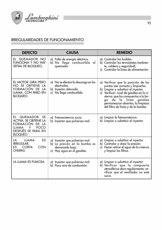
92
IRREGULARIDADES DE FUNCIONAMIENTO
REMEDIOCAUSADEFECTO
a) Falta de energía eléctrica.b) No llega combustible al
quemador.
a) No se efectúa la descarga en loselectrodos.
b) Inyector obturado.c) No llega combustible.
a) Fotoresistencia sucia.b) Inyector que pulveriza mal.
a) Inyector que pulveriza mal.b) La presión en la bomba es
demasiado baja.c) Hay agua en el gasóleo.
a) Inyector que pulveriza mal.b) Poco aire de combustión.
EL QUEMADOR NOFUNCIONA Y NO HAYSEÑAL DE BLOQUEO.
EL MOTOR GIRA PERONO SE OBTIENE LAFORMACIÓN DE LALLAMA, CON PARO ENBLOQUEO.
EL QUEMADOR SEACTIVA, SE OBTIENE LAFORMACIÓN DE LALLAMA Y POCODESPUÉS SE PARA ENBLOQUEO.
LA LLAMA ESIRREGULAR,ES CORTA CONCHISPAS.
LA LLAMA ES FUMOSA
a) Controlar los fusibles.b) Controlar los termóstatos (ambien-
te, caldera y seguridad).c) Controlar la línea de alimentación.
a) Verificar que la posición de laspuntas sea correcta y limpiarlas.
b) Limpiar y substituir el inyector.c) Verificar: nivel de gasóleo en la ci-
sterna; que las compuertas a lo lar-go de la línea gasóleopermanezcan abiertas; la limpiezadel filtro de línea y de la bomba.
a) Limpiar la fotoresistencia.b) Limpiar o substituir el inyector.
a) Limpiar o substituir el inyector.b) Controlar y alzar la presión.c) Hacer retirar el agua de la cisterna
y limpiar los filtros.
a) Limpiar o substituir el inyector.b) Verificar que la compuer ta
atmosférica abra regularmente; ve-rificar que el ventilador no estésucio.

¢È·‚¿ÛÙ ÚÔÛÂÎÙÈο ÙȘ Ô‰ËÁ›Â˜ Î·È ÙȘ ÚÔÂȉÔÔÈ‹ÛÂȘ Ô˘ ÂÚȤ¯ÔÓÙ·È ÛÙÔ ·ÚfiÓÂÁ¯ÂÈÚ›‰ÈÔ ·ÊÔ‡ ·Ú¤¯Ô˘Ó ÛËÌ·ÓÙÈΤ˜ ˘Ô‰Â›ÍÂȘ Û¯ÂÙÈΤ˜ Ì ÙËÓ ·ÛÊ¿ÏÂÈ·ÂÁηٿÛÙ·Û˘, ¯Ú‹Û˘ Î·È Û˘ÓÙ‹ÚËÛ˘. º˘Ï¿ÍÙ ÚÔÛÂÎÙÈο ÙÔ ÂÁ¯ÂÈÚ›‰ÈÔ, ÒÛÙÂÓ· ÌÔÚ›Ù ӷ ·Ó·ÙÚ¤ÍÂÙ Û ·˘Ùfi ÛÙÔ Ì¤ÏÏÔÓ.∏ ÂÁηٿÛÙ·ÛË Ú¤ÂÈ Ó· ‰ÈÂÓÂÚÁËı› ·fi ÂȉÈÎÂ˘Ì¤ÓÔ ÚÔÛˆÈÎfi Ô˘ ı· Â›Ó·È˘Â‡ı˘ÓÔ ÁÈ· ÙËÓ Ù‹ÚËÛË ÙˆÓ ÈÛ¯˘fiÓÙˆÓ Î·ÓÔÓÈÛÌÒÓ ·ÛÊ·Ï›·˜.
∂§§∏¡π∫∞ GR
94
™˘Á¯·ÚËÙ‹ÚÈ·......°È· ÙËÓ ÂÍ·ÈÚÂÙÈ΋ ÂÈÏÔÁ‹. ™·˜ ¢¯·ÚÈÛÙԇ̠ÁÈ· ÙËÓ ÚÔÙ›ÌËÛË Ô˘ ‰Â›Í·ÙÂ
ÁÈ· Ù· ÚÔ˚fiÓÙ· Ì·˜.∏ LAMBORGHINI CALORECLIMA Â›Ó·È ·fi ÙÔ 1959 ÂÓÂÚÁ¿ ·ÚÔ‡Û· ÛÙËÓ πÙ·Ï›· ηÈÛÙÔÓ ÎfiÛÌÔ Ì ¤Ó· ‰›ÎÙ˘Ô ‰È·ÓÔÌ‹˜ ¶Ú·ÎÙfiÚˆÓ Î·È ·ÓÙÈÚÔÛÒˆÓ, Ô˘ ÂÁÁ˘ÒÓÙ·ÈÛÙ·ıÂÚ¿ ÙËÓ ·ÚÔ˘Û›· ÙÔ˘ ÚÔ˚fiÓÙÔ˜ ÛÙËÓ ·ÁÔÚ¿. ™Â ·˘Ùfi ÚÔÛÙ›ıÂÙ·È Î·È ÌÈ· ̆ ËÚÂÛ›·Ù¯ÓÈ΋˜ ˘ÔÛÙ‹ÚÈ͢, “LAMBORGHINI SERVICE”, ÛÙËÓ ÔÔ›· ·ʛÂÙ·È Ë ÔÈÔÙÈÎ‹Û˘ÓÙ‹ÚËÛË ÙÔ˘ ÚÔ˚fiÓÙÔ˜.
°È· ÙËÓ ÂÁηٿÛÙ·ÛË Î·È ÁÈ· ÙËÓ ÙÔÔı¤ÙËÛË ÙÔ˘ η˘ÛÙ‹Ú·:
∆∏ƒ∏™∆∂ ∂¶∞∫ƒπµø™ ∆√À™ π™ÃÀ√¡∆∂™ ∆√¶π∫√À™ ∫∞¡√¡π™ª√À™
¶∂ƒπ∂Ã√ª∂¡∞ ™∂§π¢∞
∆∂áπ∫∞ Ã∞ƒ∞∫∆∏ƒπ™∆π∫∞ ___________________ 95¢π∞™∆∞™∂π™ ____________________________________ 95∫∞ª¶À§∂™ ∂ƒ°∞™π∞™________________________ 96™À¡∞ƒª√§√°∏™∏ ™∆√ §∂µ∏∆∞_______________ 96∏§∂∫∆ƒπ∫∂™ ™À¡¢∂™∂π™ _____________________ 97∆ƒ√º√¢√™π∞ ¶∂∆ƒ∂§∞π√À ___________________ 99∆ƒ√º√¢√™π∞ ª√¡√™ø§∏¡ø∆∏ _______________ 99∆ƒ√º√¢√™π∞ ¢π™ø§∏¡ø∆∏ ___________________ 99∂¶π§√°∏ ∞∫ƒ√ºÀ™π√À______________________ 100¶∞ƒ∞¢∂π°ª∞ ∂¶π§√°∏™ ∞∫ƒ√ºÀ™π√À ________ 100™À¡∞ƒª√§√°∏™∏ ∞∫ƒ√ºÀ™π√À _____________ 100∆√¶√£∂∆∏™∏ ∏§∂∫∆ƒ√¢πø¡-∂∫∆ƒ√¶∂∞ _____ 101∫À∫§√™ §∂π∆√Àƒ°π∞™ ______________________ 101™À™∫∂À∫ LMO _____________________________ 104ƒÀ£ªπ™∏ ∫∂º∞§∏™ ________________________ 105ƒÀ£ªπ™∏ ∞∂ƒ∞ ∫∞À™∏™ (ECO 30) ______________ 105ƒÀ£ªπ™∏ ∞∂ƒ∞ ∫∞À™∏™ (ECO 30/2 - ECO 40/2) __ 105£∂™∏ ™∂ §∂π∆√Àƒ°π∞ _______________________ 106ƒÀ£ªπ™∏ ¶π∂™∏™ ∞¡∆§π∞™ __________________ 107∂§∂°Ã√™ ∫∞À™∏™ __________________________ 107™À¡∆∏ƒ∏™∏ _______________________________ 108ºø∆√∞¡∆π™∆∞™∏___________________________ 108ºπ§∆ƒ√ ∞¡∆§π∞™ ___________________________ 108ºπ§∆ƒ√ °ƒ∞ªª∏™ _________________________ 108∞¡∂ªπ™∆∏ƒ∞™ ∫§∂π™∆ƒ√À ∞∂ƒ∞ _____________ 108∏§∂∫∆ƒ√¢π∞ ∞∫ƒ√ºÀ™π√À __________________ 109∞¡øª∞§π∞ §∂π∆√Àƒ°π∞™ ____________________ 110
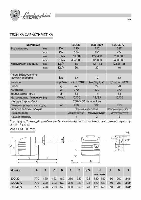
95
∆∂áπ∫∞ Ã∞ƒ∞∫∆∏ƒπ™∆π∫∞
¶·Ú·Ù‹ÚËÛË: ∆· ÛÙÔȯ›· ÌÂٷ͇ ·ÚÂÓı¤ÛÂˆÓ ·Ó·Ê¤ÚÔÓÙ·È ÛÙËÓ ÂÏ¿¯ÈÛÙË ÂÈÙ˘Á¯·ÓfiÌÂÓË ·ÚÔ¯‹Ì ÙËÓ 1Ë ÊÏfiÁ·.
¢π∞™∆∞™∂π™ mm
X
F H
L
M8
N
A B
C
ED
H Nø G
min maxªÔÓÙ¤ÏÔ A B C D E F Ø G H L N X
ECO 30 770 420 423 460 310 350 135 120 160 150 200 3/8”ECO 30/2 770 420 423 460 330 350 135 120 160 150 200 3/8”ECO 40/2 790 420 423 460 330 350 148 120 160 160 200 3/8”
ª√¡∆∂§√ ECO 30 ECO 30/2 ECO 40/2£ÂÚÌÈ΋ ÈÛ¯‡˜ min. kW 190 142 267
max. kW 356 356 474min. kcal/h 163.000 122.400 230.000max. kcal/h 306.000 306.000 408.000
∫·Ù·Ó¿ÏˆÛË Î·˘Û›ÌÔ˘ min. Kg/h 16 (12) - 14 (22,5) - 25max. Kg/h 30 30 40
¶›ÂÛË µ·ıÌÔÓfiÌËÛ˘ ·ÓÙÏ›·˜ η˘Û›ÌÔ˘ bar 12 12 12
∫·‡ÛÈÌÔ ÂÙڤϷÈÔ p.c.i. 10210 Kcal/Kg 1,5°E (6cst) Û 20ÆC
µ¿ÚÔ˜ kg 26,5 27 28∫ÈÓËÙ‹Ú·˜ W 370 370 370™˘Ì˘ÎÓˆÙ‹˜ 450 V µF 14 14 14ªÂÙ·Û¯ËÌ·ÙÈÛÙ‹˜ ·Ó¿ÊÏÂ͢ kV/mA 12/35 12/35 12/35∏ÏÂÎÙÚÈ΋ ÙÚÔÊÔ‰ÔÛ›· 230V - 50 Hz monofase√ÏÈ΋ ·ÔÚÚÔÊÔ‡ÌÂÓË ÈÛ¯‡˜ W 850 900 950™˘Û΢‹ ÂϤÁ¯Ô˘ ÊÏfiÁ·˜ £ÂÚÌÈ΋ c/ʈÙÔ·ÓÙ. ∏ÏÂÎÙÚÔÓÈ΋ c/ʈÙÔ·ÓÙ.
ƒ‡ıÌÈÛË ·¤Ú· ÃÂÈÚÔÓ·ÎÙÈ΋ ªË¯·ÓÔΛÓËÙË ªË¯·ÓÔΛÓËÙË
∞ÚÈıÌfi˜ ÛÙ·‰›ˆÓ 1 2 2

96
∫∞ª¶À§∂™ ∂ƒ°∞™π∞™
¢Â›¯ÓÔ˘Ó ÙËÓ ÈÛ¯‡ Û kW, ÛÂ Û˘Ó¿ÚÙËÛË Ù˘ ·ÓÙÈ-›ÂÛ˘, Û mbar, ÛÙÔ ı·Ï¿ÌÔ˘ η‡Û˘.
ECO 30
100 130 160 190 220 250 280 310 340 370 400 430 460 490 520 550POTENZA kW
6
4
3
2
1
0PRES
SIO
NE
IN C
AM
ERA
DI C
OM
BUST
ION
E m
bar
ECO 40/2
5
ECO 30/2
™À¡∞ƒª√§√°∏™∏ ™∆√ §∂µ∏∆∞
™ÙÂÚÂÒÛÙ ÙË ÊÏ¿ÓÙ˙· 2 ÛÙÔ Ï¤‚ËÙ· Ì 4 ‚›‰Â˜ 3 ·ÚÂÌ‚¿ÏÏÔÓÙ·˜ ÙÔ ·Ú¤Ì‚˘ÛÌ· ÛÙÂÁ·ÓÔÔ›ËÛ˘4 Î·È ÙÔ ÂӉ¯fiÌÂÓÔ ÌÔÓˆÙÈÎfi Û¯ÔÈÓ› 5. µ¿ÏÙ ÙÔÓ Î·˘ÛÙ‹Ú· ÛÙËÓ ÊÏ¿ÓÙ˙· ¤ÙÛÈ ÒÛÙ ÙÔ ·ÎÚÔÛÙfiÌÈÔÓ· ‰ÈÂÈÛ‰‡ÛÂÈ ÛÙÔ ı¿Ï·ÌÔ Î·‡Û˘ Û‡Ìʈӷ Ì ÙȘ ˘Ô‰Â›ÍÂȘ ÙÔ˘ ηٷÛ΢·ÛÙ‹ ÙÔ˘ Ϥ‚ËÙ·. ™Ê›ÍÙÂÙË ‚›‰· 1 ÁÈ· Ó· ·ÛÊ·Ï›ÛÂÙ ÙÔÓ Î·˘ÛÙ‹Ú·.
1 4
3 2 5

97
∏§∂∫∆ƒπ∫∂™ ™À¡¢∂™∂π™
√È ÚÔ˜ ÂÎÙ¤ÏÂÛË Û˘Ó‰¤ÛÂȘ ·fi ÙÔÓ Ù¯ÓÈÎfi ÂÁηٿÛÙ·Û˘ ›ӷÈ:● ÁÚ·ÌÌ‹ ÙÚÔÊÔ‰ÔÛ›·˜● lıÂÚÌÔÛÙ·ÙÈ΋ ÁÚ·ÌÌ‹● ÂӉ¯fiÌÂÓË Ï˘¯Ó›· ÌÏÔηڛÛÌ·ÙÔ˜● ÂӉ¯fiÌÂÓÔ ¯ÚÔÓfiÌÂÙÚÔ● ÂӉ¯fiÌÂÓÔ˜ ıÂÚÌÔÛÙ¿Ù˘ ‰È·ÌfiÚʈÛ˘ ÊÏfiÁ·˜
(‚Á¿ÏÙ ÙÔ Î·ÏÒ‰ÈÔ Ô˘ ÁÂÊ˘ÚÒÓÂÈ)
¶·Ú·Ù‹ÚËÛË: Â›Ó·È ··Ú·›ÙËÙÔ Ó· ÂÊ·ÚÌfi˙ÂÙ ·˘ÛÙËÚ¿ ÙÔÓ Î·Ïfi ηÓfiÓ· Ô˘ ÔÚ›˙ÂÈ ÙË Û‡Ó‰ÂÛËÙÔ Ôχ ‰‡Ô ηψ‰›ˆÓ ·Ó¿ ·ÎÚÔ‰¤ÎÙË.
¶ÚÔÛÔ¯‹:
● ÌËÓ ÂÓ·ÏÏ¿ÛÛÂÙ ÙÔ Ô˘‰¤ÙÂÚÔ Ì ÙË Ê¿ÛË● ÂÎÙÂϤÛÙ ÌÈ· ηϋ Û‡Ó‰ÂÛË Á›ˆÛ˘● ÙËÚ‹ÛÙ ÙÔ˘˜ ηÓfiÓ˜ Ù˘ ¿ÚÙÈ·˜ Ù¯ÓÈ΋˜ Î·È ÂÊ·ÚÌfiÛÙ ·ÎÚÈ‚Ò˜ ÙÔ˘˜ ÙÔÈÎÔ‡˜ ÈÛ¯‡ÔÓÙ˜
ηÓfiÓ˜
ECO 30
MPELOA 24.../LMO14...
À¶√ª¡∏ª∞
F ∞ÛÊ¿ÏÂÈ·FA º›ÏÙÚÔ ıÔÚ‡‚Ô˘FCA ∞ÛÊ¿ÏÂÈ· ÂʉÚÈÎÔ‡ ΢ÎÏÒÌ·ÙÔ˜FR ºˆÙÔ·ÓÙ›ÛÙ·ÛËIG °ÂÓÈÎfi˜ ‰È·ÎfiÙ˘IMA ¢È·ÎfiÙ˘ ΛÓËÛ˘-·‡Û˘
MB ∫ÈÓËÙ‹Ú·˜ η˘ÛÙ‹Ú·MPE ∞ÎÚÔ‰. ™˘ÛÎ. LandisTC £ÂÚÌÔÛÙ¿Ù˘ Ϥ‚ËÙ·TS £ÂÚÌÔÛÙ¿Ù˘ ·ÛÊ·Ï›·˜TR ªÂÙ·Û¯ËÌ·ÙÈÛÙ‹˜ ·Ó¿ÊÏÂ͢VE ∏ÏÂÎÙÚÔÌ·ÁÓËÙÈ΋ µ·Ï‚›‰·
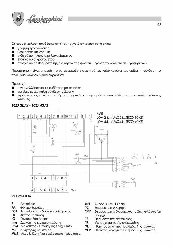
98
√È ÚÔ˜ ÂÎÙ¤ÏÂÛË Û˘Ó‰¤ÛÂȘ ·fi ÙÔÓ Ù¯ÓÈÎfi ÂÁηٿÛÙ·Û˘ ›ӷÈ:
● ÁÚ·ÌÌ‹ ÙÚÔÊÔ‰ÔÛ›·˜● ıÂÚÌÔÛÙ·ÙÈ΋ ÁÚ·ÌÌ‹● ÂӉ¯fiÌÂÓË Ï˘¯Ó›· ÌÏÔηڛÛÌ·ÙÔ˜● ÂӉ¯fiÌÂÓÔ ¯ÚÔÓfiÌÂÙÚÔ● ÂӉ¯fiÌÂÓÔ˜ ıÂÚÌÔÛÙ¿Ù˘ ‰È·ÌfiÚʈÛ˘ ÊÏfiÁ·˜ (‚Á¿ÏÙ ÙÔ Î·ÏÒ‰ÈÔ Ô˘ ÁÂÊ˘ÚÒÓÂÈ)
¶·Ú·Ù‹ÚËÛË: Â›Ó·È ··Ú·›ÙËÙÔ Ó· ÂÊ·ÚÌfi˙ÂÙ ·˘ÛÙËÚ¿ ÙÔÓ Î·Ïfi ηÓfiÓ· Ô˘ ÔÚ›˙ÂÈ ÙË Û‡Ó‰ÂÛË ÙÔ
Ôχ ‰‡Ô ηψ‰›ˆÓ ·Ó¿ ·ÎÚÔ‰¤ÎÙË.
¶ÚÔÛÔ¯‹:● ÌËÓ ÂÓ·ÏÏ¿ÛÛÂÙ ÙÔ Ô˘‰¤ÙÂÚÔ Ì ÙË Ê¿ÛË● ÂÎÙÂϤÛÙ ÌÈ· ηϋ Û‡Ó‰ÂÛË Á›ˆÛ˘● ÙËÚ‹ÛÙ ÙÔ˘˜ ηÓfiÓ˜ Ù˘ ¿ÚÙÈ·˜ Ù¯ÓÈ΋˜ Î·È ÂÊ·ÚÌfiÛÙ ·ÎÚÈ‚Ò˜ ÙÔ˘˜ ÙÔÈÎÔ‡˜ ÈÛ¯‡ÔÓÙ˜
ηÓfiÓ˜
ECO 30/2 - ECO 40/2
1 2 2 3 4 5 6 7 8 10 11 129
M
MB
VE1
TC
TS F IG
B4
T2T1N
L1
S3
L
N
FR
2
IMA
3 5 6 1 8 N4 7 MMS
VE2
TR
FA
FCA
2 3 4 5 6 71 8 9
2N
ImM
TMF
31
L1
À¶√ª¡∏ª∞
F ∞ÛÊ¿ÏÂÈ·FA º›ÏÙÚÔ ıÔÚ‡‚Ô˘FCA ∞ÛÊ¿ÏÂÈ· ÂʉÚÈÎÔ‡ ΢ÎÏÒÌ·ÙÔ˜FR ºˆÙÔ·ÓÙ›ÛÙ·ÛËIG °ÂÓÈÎfi˜ ‰È·ÎfiÙ˘Ima ¢È·ÎfiÙ˘ ΛÓËÛ˘-·‡Û˘ImM ¢È·ÎfiÙ˘ ÏÂÈÙÔ˘ÚÁ›·˜ ÂÏ¿¯.- max.MB ∫ÈÓËÙ‹Ú·˜ η˘ÛÙ‹Ú·MMS ∞ÎÚÔ‰. ∫ÈÓËÙ‹Ú· ÛÂÚ‚Ô¯ÂÈÚÈÛÙËÚ›Ô˘ ·¤Ú·
MPE ∞ÎÚÔ‰. ™˘ÛÎ. LandisTC £ÂÚÌÔÛÙ¿Ù˘ Ϥ‚ËÙ·TMF £ÂÚÌÔÛÙ¿Ù˘ ‰È·ÌfiÚʈÛ˘ 2˘ ÊÏfiÁ·˜ (·Ó
˘¿Ú¯ÂÈ)TS £ÂÚÌÔÛÙ¿Ù˘ ·ÛÊ·Ï›·˜TR ªÂÙ·Û¯ËÌ·ÙÈÛÙ‹˜ ·Ó¿ÊÏÂ͢VE1 ∏ÏÂÎÙÚÔÌ·ÁÓËÙÈ΋ µ·Ï‚›‰· 1˘ ÊÏfiÁ·˜VE2 ∏ÏÂÎÙÚÔÌ·ÁÓËÙÈ΋ µ·Ï‚›‰· 2˘ ÊÏfiÁ·˜
MPELOA 24.../LMO24...(ECO 30/2)LOA 44.../LMO44...(ECO 40/2)
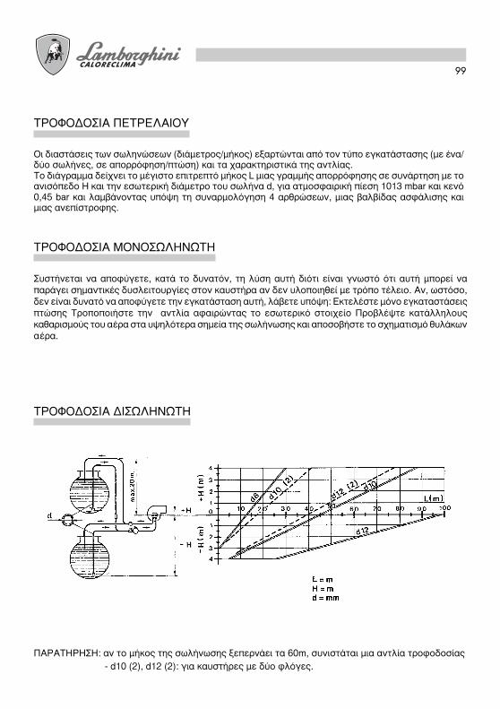
99
∆ƒ√º√¢√™π∞ ¶∂∆ƒ∂§∞π√À
√È ‰È·ÛÙ¿ÛÂȘ ÙˆÓ ÛˆÏËÓÒÛÂˆÓ (‰È¿ÌÂÙÚÔ˜/Ì‹ÎÔ˜) ÂÍ·ÚÙÒÓÙ·È ·fi ÙÔÓ Ù‡Ô ÂÁηٿÛÙ·Û˘ (Ì ¤Ó·/‰‡Ô ۈϋÓ˜, Û ·ÔÚÚfiÊËÛË/ÙÒÛË) Î·È Ù· ¯·Ú·ÎÙËÚÈÛÙÈο Ù˘ ·ÓÙÏ›·˜.∆Ô ‰È¿ÁÚ·ÌÌ· ‰Â›¯ÓÂÈ ÙÔ Ì¤ÁÈÛÙÔ ÂÈÙÚÂÙfi Ì‹ÎÔ˜ L ÌÈ·˜ ÁÚ·ÌÌ‹˜ ·ÔÚÚfiÊËÛ˘ ÛÂ Û˘Ó¿ÚÙËÛË Ì ÙÔ·ÓÈÛfiÂ‰Ô H Î·È ÙËÓ ÂÛˆÙÂÚÈ΋ ‰È¿ÌÂÙÚÔ ÙÔ˘ ۈϋӷ d, ÁÈ· ·ÙÌÔÛÊ·ÈÚÈ΋ ›ÂÛË 1013 mbar Î·È ÎÂÓfi0,45 bar Î·È Ï·Ì‚¿ÓÔÓÙ·˜ ˘fi„Ë ÙË Û˘Ó·ÚÌÔÏfiÁËÛË 4 ·ÚıÚÒÛˆÓ, ÌÈ·˜ ‚·Ï‚›‰·˜ ·ÛÊ¿ÏÈÛ˘ ηÈÌÈ·˜ ·Ó›ÛÙÚÔÊ˘.
∆ƒ√º√¢√™π∞ ª√¡√™ø§∏¡ø∆∏
™˘ÛÙ‹ÓÂÙ·È Ó· ·ÔʇÁÂÙÂ, ηٿ ÙÔ ‰˘Ó·ÙfiÓ, ÙË Ï‡ÛË ·˘Ù‹ ‰ÈfiÙÈ Â›Ó·È ÁÓˆÛÙfi fiÙÈ ·˘Ù‹ ÌÔÚ› Ó··Ú¿ÁÂÈ ÛËÌ·ÓÙÈΤ˜ ‰˘ÛÏÂÈÙÔ˘ÚÁ›Â˜ ÛÙÔÓ Î·˘ÛÙ‹Ú· ·Ó ‰ÂÓ ˘ÏÔÔÈËı› Ì ÙÚfiÔ Ù¤ÏÂÈÔ. ∞Ó, ˆÛÙfiÛÔ,‰ÂÓ Â›Ó·È ‰˘Ó·Ùfi Ó· ·ÔʇÁÂÙ ÙËÓ ÂÁηٿÛÙ·ÛË ·˘Ù‹, Ï¿‚ÂÙ ̆ fi„Ë: ∂ÎÙÂϤÛÙ ÌfiÓÔ ÂÁηٷÛÙ¿ÛÂȘÙÒÛ˘ ∆ÚÔÔÔÈ‹ÛÙ ÙËÓ ·ÓÙÏ›· ·Ê·ÈÚÒÓÙ·˜ ÙÔ ÂÛˆÙÂÚÈÎfi ÛÙÔÈ¯Â›Ô ¶ÚԂϤ„Ù ηٿÏÏËÏÔ˘˜Î·ı·ÚÈÛÌÔ‡˜ ÙÔ˘ ·¤Ú· ÛÙ· ̆ „ËÏfiÙÂÚ· ÛËÌ›· Ù˘ ۈϋӈÛ˘ Î·È ·ÔÛÔ‚‹ÛÙ ÙÔ Û¯ËÌ·ÙÈÛÌfi ı˘Ï¿ÎˆÓ·¤Ú·.
∆ƒ√º√¢√™π∞ ¢π™ø§∏¡ø∆∏
¶∞ƒ∞∆∏ƒ∏™∏: ·Ó ÙÔ Ì‹ÎÔ˜ Ù˘ ۈϋӈÛ˘ ÍÂÂÚÓ¿ÂÈ Ù· 60m, Û˘ÓÈÛÙ¿Ù·È ÌÈ· ·ÓÙÏ›· ÙÚÔÊÔ‰ÔÛ›·˜
- d10 (2), d12 (2): ÁÈ· η˘ÛÙ‹Ú˜ Ì ‰‡Ô ÊÏfiÁ˜.

100
∂¶π§√°∏ ∞∫ƒ√ºÀ™π√À
PRESSIONE POMPA bar (kg/cm2 )UGELLO
GPH
2,00
2,50
3,00
3,50
4,00
4,50
5,00
6,00
7,00
8,30
9,50
10,50
10 11 12 13 14 15 16 17 18 19 20 21
7,43 7,75 8,10 8,42 8,80 9,05 9,35 9,67 9,91 10,22 10,48 10,70
88,12 91,91 96,06 99,86 104,37 107,33 110,90 114,68 117,53 121,21 124,30 126,909,28 9,67 10,17 10,54 10,98 11,27 11,70 12,10 12,38 12,76 13,10 13,40
110,06 114,68 120,62 125,00 130,22 133,66 138,76 143,50 146,82 151,33 155,36 158,9211,17 11,60 12,16 12,65 13,20 13,60 14,10 14,50 14,88 15,16 15,70 16,10
132,47 137,58 144,22 150,03 156,55 161,30 167,22 171,98 176,47 179,80 186,20 190,9413,05 13,60 14,20 14,78 15,40 15,85 16,40 16,95 17,38 17,90 18,30 18,80
154,77 161,30 168,41 175,29 182,64 187,98 194,50 201,03 206,12 212,29 217,04 222,97
14,88 15,50 16,24 16,90 17,60 18,12 18,70 19,37 19,88 20,40 21,00 21,50176,47 183,83 192,60 200,43 208,73 214,90 221,78 229,73 235,77 241,94 249,06 255,0016,67 17,35 18,20 18,90 19,70 20,30 21,00 21,70 22,25 22,90 23,50 24,00
197,70 205,77 215,85 224,15 233,64 240,76 249,06 257,36 263,88 271,60 278,71 284,6418,60 19,35 20,30 21,10 22,00 22,60 23,35 24,15 24,80 25,50 26,20 26,70
220,60 229,49 240,76 250,24 260,92 268,03 286,42 294,13 307,36 310,73 316,6622,30 23,25 24,35 25,30 26,40 27,20
276,9329,00 29,75 30,75 31,40 32,20
264,48 275,74 288,80 300,06 313,10 322,59
28,10
343,94 352,83 364,49 372,40 381,9026,00 27,15 28,40 29,50 30,70 31,70
333,2633,90 34,80 35,80 36,65 37,50
308,36 322,00 336,82 349,87 364,10 375,9632,70
402,05 412,73 424,59 434,67 444,7530,80 32,10 33,60 34,90 36,40 37,50
387,8240,20
365,29 380,70 398,50 413,91 431,70 444,75
38,75
476,7735,30 36,70 38,50 40
45957
418,66 435,26 456,61 474,439,00 40,65
462,54 482,11
¶∞ƒ∞¢∂π°ª∞ ∂¶π§√°∏™ ∞∫ƒ√ºÀ™π√À
™À¡∞ƒª√§√°∏™∏ ∞∫ƒ√ºÀ™π√À
√ Ϥ‚ËÙ·˜ ¤¯ÂÈ ÌÈ· ÈÛ¯‡ ÂÛÙ›·˜ 290 kW.°È· ÌÈ· ›ÂÛË ÛÙËÓ ·ÓÙÏ›· 12 bar, Ë ÏËÛȤÛÙÂÚË ÙÈÌ‹ Â›Ó·È kW 288,80 ÛÙËÓ ÔÔ›· ·ÓÙÈÛÙÔȯ› ¤Ó··ÎÚÔʇÛÈÔ ÙˆÓ 6 GPH. ∞Ó Ô Î·˘ÛÙ‹Ú·˜ Â›Ó·È Ì ‰‡Ô ·ÎÚÔʇÛÈ·, ̄ ˆÚ›ÛÙ ÙËÓ ·ÚÔ¯‹ Ì ¤Ó· ·ÎÚÔʇÛÈÔÙˆÓ 2,50 GPH ÛÙËÓ ÚÒÙË ÊÏfiÁ· Î·È ÙˆÓ 3,50 GPH ÛÙË ‰Â‡ÙÂÚË.∞Ó ‰ÂÓ ‰È·ı¤ÙÂÙ ÙÔ ‚¤ÏÙÈÛÙÔ ·ÎÚÔʇÛÈÔ ÌÔÚ›ÙÂ, ÂÓÙfi˜ ÙˆÓ ÔÚ›ˆÓ 11 - 14 bar, Ó· ·ÏÏ¿ÍÂÙ ÙËÓ›ÂÛË Ù˘ ·ÓÙÏ›·˜ ÁÈ· Ó· ÂÙ‡¯ÂÙ ÙËÓ ÂÈı˘ÌËÙ‹ ·ÚÔ¯‹.
∞ÊÔ‡ ÂÈÏÂÁ› ÙÔ Î·Ù¿ÏÏËÏÔ ·ÎÚÔʇÛÈÔ, ÚÔ¯ˆÚ‹ÛÙ ÛÙË Û˘Ó·ÚÌÔÏfiÁËÛË fiˆ˜ ˘Ô‰ÂÈÎÓ‡ÂÙ·ÈÛÙËÓ ·Ú¿ÁÚ·ÊÔ “™À¡∆∏ƒ∏™∏”

101
∆√¶√£∂∆∏™∏ ∏§∂∫∆ƒ√¢πø¡-∂∫∆ƒ√¶∂∞
∞ÊÔ‡ ÌÔÓÙ¿ÚÂÙ ÙÔ ·ÎÚÔʇÛÈÔ (‹ Ù· ·ÎÚÔʇÛÈ·), ÂϤÁÍÙ ÙË ÛˆÛÙ‹ ÙÔÔı¤ÙËÛË ËÏÂÎÙÚÔ‰›ˆÓ ηÈÂÎÙÚÔ¤·, Û‡Ìʈӷ Ì ٷ ·Ó·ÊÂÚfiÌÂÓ· ‡„Ë (mm). ∂›Ó·È ÛÎfiÈÌÔ Ó· ‰ÈÂÓÂÚÁ‹ÛÂÙ ÌÈ· ·ϋı¢ÛËÙˆÓ ˘„ÒÓ ÌÂÙ¿ ·fi οı ¤̂·ÛË ÛÙËÓ ÎÂÊ·Ï‹.
ECO 30 ECO 30/2 - ECO 40/2
∫À∫§√™ §∂π∆√Àƒ°π∞™
A - ¤Ó·ÚÍË ÂÎΛÓËÛ˘B - ·ÚÔ˘Û›· ÊÏfiÁ·˜C - Ù¤ÏÔ˜ ÂÎΛÓËÛ˘C-D - ÏÂÈÙÔ˘ÚÁ›· ηÓÔÓÈ΋D - ÛÙ·Ì¿ÙËÌ· Ú‡ıÌÈÛ˘ (TA-TC)
T1 ¯ÚfiÓÔ˜ ÚÔ-·ÂÚÈÛÌÔ‡ 13 sec. 15 sec.T2 ¯ÚfiÓÔ˜ ·ÛÊ·Ï›·˜ 10 sec. 10 sec.T3 ¯ÚfiÓÔ˜ ÚÔ·Ó¿ÊÏÂ͢ 13 sec. 15 sec.T3n ¯ÚfiÓÔ˜ ÌÂÙ·-·Ó¿ÊÏÂ͢15 sec. 10 sec.
ECO 30
£ÂÚÌÔÛÙ¿Ù˘ ÂÚÈ‚. – Ϥ‚ËÙ·˜
∫ÈÓËÙ‹Ú·˜
ªÂÙ·Û¯ËÌ·ÙÈÛÙ‹˜
∏ÏÂÎÙÚÔÌ·ÁÓËÙÈ΋ ‚·Ï‚›‰·
ºˆÙÔ·ÓÙ›ÛÙ·ÛË
LOA 24 LMO 14
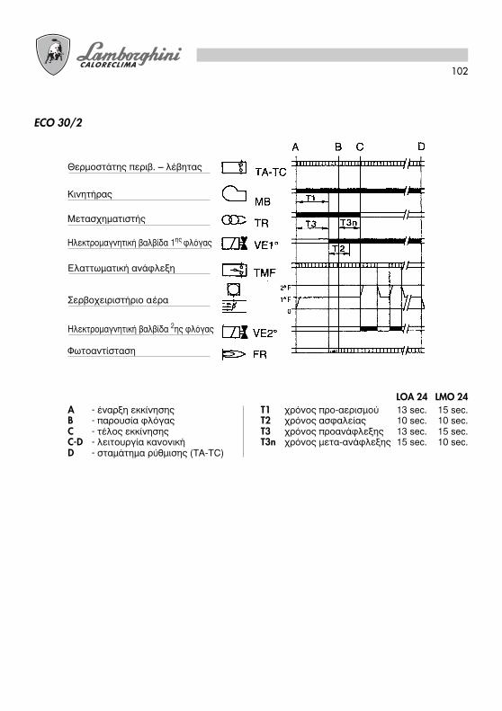
102
A - ¤Ó·ÚÍË ÂÎΛÓËÛ˘B - ·ÚÔ˘Û›· ÊÏfiÁ·˜C - Ù¤ÏÔ˜ ÂÎΛÓËÛ˘C-D - ÏÂÈÙÔ˘ÚÁ›· ηÓÔÓÈ΋D - ÛÙ·Ì¿ÙËÌ· Ú‡ıÌÈÛ˘ (TA-TC)
T1 ¯ÚfiÓÔ˜ ÚÔ-·ÂÚÈÛÌÔ‡ 13 sec. 15 sec.T2 ¯ÚfiÓÔ˜ ·ÛÊ·Ï›·˜ 10 sec. 10 sec.T3 ¯ÚfiÓÔ˜ ÚÔ·Ó¿ÊÏÂ͢ 13 sec. 15 sec.T3n ¯ÚfiÓÔ˜ ÌÂÙ·-·Ó¿ÊÏÂ͢ 15 sec. 10 sec.
ECO 30/2
£ÂÚÌÔÛÙ¿Ù˘ ÂÚÈ‚. – Ϥ‚ËÙ·˜
∫ÈÓËÙ‹Ú·˜
ªÂÙ·Û¯ËÌ·ÙÈÛÙ‹˜
∏ÏÂÎÙÚÔÌ·ÁÓËÙÈ΋ ‚·Ï‚›‰· 1˘ ÊÏfiÁ·˜
ºˆÙÔ·ÓÙ›ÛÙ·ÛË
∂Ï·Ùو̷ÙÈ΋ ·Ó¿ÊÏÂÍË
™ÂÚ‚Ô¯ÂÈÚÈÛÙ‹ÚÈÔ ·¤Ú·
∏ÏÂÎÙÚÔÌ·ÁÓËÙÈ΋ ‚·Ï‚›‰· 2˘ ÊÏfiÁ·˜
LOA 24 LMO 24
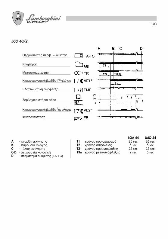
103
A - ¤Ó·ÚÍË ÂÎΛÓËÛ˘B - ·ÚÔ˘Û›· ÊÏfiÁ·˜C - Ù¤ÏÔ˜ ÂÎΛÓËÛ˘C-D - ÏÂÈÙÔ˘ÚÁ›· ηÓÔÓÈ΋D - ÛÙ·Ì¿ÙËÌ· Ú‡ıÌÈÛ˘ (TA-TC)
ECO 40/2
£ÂÚÌÔÛÙ¿Ù˘ ÂÚÈ‚. – Ϥ‚ËÙ·˜
∫ÈÓËÙ‹Ú·˜
ªÂÙ·Û¯ËÌ·ÙÈÛÙ‹˜
∏ÏÂÎÙÚÔÌ·ÁÓËÙÈ΋ ‚·Ï‚›‰· 1˘ ÊÏfiÁ·˜
ºˆÙÔ·ÓÙ›ÛÙ·ÛË
∂Ï·Ùو̷ÙÈ΋ ·Ó¿ÊÏÂÍË
™ÂÚ‚Ô¯ÂÈÚÈÛÙ‹ÚÈÔ ·¤Ú·
∏ÏÂÎÙÚÔÌ·ÁÓËÙÈ΋ ‚·Ï‚›‰· 2˘ ÊÏfiÁ·˜
LOA 44 LMO 44T1 ¯ÚfiÓÔ˜ ÚÔ-·ÂÚÈÛÌÔ‡ 25 sec. 26 sec.T2 ¯ÚfiÓÔ˜ ·ÛÊ·Ï›·˜ 5 sec. 5 sec.T3 ¯ÚfiÓÔ˜ ÚÔ·Ó¿ÊÏÂ͢ 25 sec. 25 sec.T3n ¯ÚfiÓÔ˜ ÌÂÙ·-·Ó¿ÊÏÂ͢ 2 sec. 5 sec.
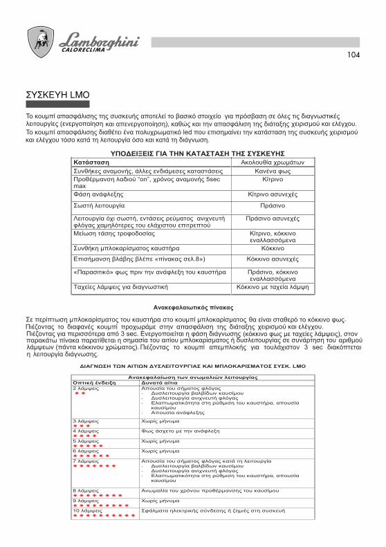
104
™Y™∫EYH LMO

105
ƒÀ£ªπ™∂π™ ∞∂ƒ∞ ∫∞À™∏™ (ECO 30)
∏ ‰È¿Ù·ÍË Ì ÌÈÎÚÔÌÂÙÚÈ΋ ‚›‰·, ¿ÌÂÛ˘ÚÔÛ‚·ÛÈÌfiÙËÙ·˜ ÂÈÙÚ¤ÂÈ Ôχ ·ÎÚÈ‚‹, ÛÙ·ıÂÚ‹Î·È ÏÂÙÔÌÂÚ‹ Ú‡ıÌÈÛË ÙÔ˘ ÂÍÂÚ¯fiÌÂÓÔ˘ ·¤Ú·.
∞ÊÔ‡ ÍÂÛÊ›ÍÂÙ ÙÔ ·ÍÈÌ¿‰È, ÛÙÚ¤„Ù ÙË ‚›‰·‰ÂÍÈfiÛÙÚÔÊ· ÁÈ· Ó· ÌÂÈÒÛÂÙ ÙÔ ¿ÓÔÈÁÌ· Ù˘ÂÙ·ÏÔ‡‰·˜. ∞ÓÙ›ÛÙÚÔÊ·, ÛÙÚ¤„Ù ÙËÓ·ÚÈÛÙÂÚfiÛÙÚÔÊ· ÁÈ· Ó· ÙÔ ·˘Í‹ÛÂÙ ·Ó·ÊÂÚfiÌÂÓÔÈÛÙËÓ ÈӷΛ‰·.
ƒÀ£ªπ™∏ ∫∂º∞§∏™
∂ÓÂÚÁÒÓÙ·˜ ÛÙË ‚›‰· A ÙÚÔÔÔÈÂ›Ù·È Ë ı¤ÛË Ù˘ÁÚ·ÌÌ‹˜ ·ÎÚÔÊ˘Û›Ô˘/ÂÎÙÚÔ¤· Û ۯ¤ÛË Ì ÙÔ·ÎÚÔÛÙfiÌÈÔ, ·ÏÏ¿˙ÔÓÙ·˜, Û˘ÓÂÒ˜, ÙË ‰È·ÙÔÌ‹‰È¤Ï¢Û˘ ÙÔ˘ ·¤Ú·.
∆Ô ÎÏ›ÛÙÚÔ ·¤Ú· ÂÓÂÚÁÔÔÈÂ›Ù·È ·fi ÙÔÓ ÌÂȈًڷÛÙÚÔÊÒÓ.
∏ Ú‡ıÌÈÛË ÙˆÓ ı¤ÛÂˆÓ ÎÏÂÈÛÙfi/·ÓÔȯÙfi, 1˘ ÊÏfiÁ·˜/·ÓÔȯÙfi max., ¢ÈÂÓÂÚÁÂ›Ù·È ÛÙ· ¤ÎÎÂÓÙÚ·ÛÙÚ¤ÊÔÓÙ·˜ ·ÚÈÛÙÂÚfiÛÙÚÔÊ· ÁÈ· Ó· ·˘Í‹ÛÂÙ ÙÔ¿ÓÔÈÁÌ· ÙÔ˘ ÚÔÏÔ‡ Î·È ‰ÂÍÈfiÛÙÚÔÊ· ÁÈ· Ó· ÙÔÌÂÈÒÛÂÙÂ.
ƒÀ£ªπ™∂π™ ∞∂ƒ∞ ∫∞À™∏™ (ECO 30/2 - ECO 40/2)
ŒÎÎÂÓÙÚÔ ÌÏ £¤ÛË ÔÏÈÎÔ‡ ÎÏÂÈ̷ۛÙÔ˜ŒÎÎÂÓÙÚÔ ÔÚÙÔηϛ ƒ‡ıÌÈÛË ·¤Ú· 1˘ ÊÏfiÁ·˜.ŒÎÎÂÓÙÚÔ ÎfiÎÎÈÓÔ ƒ‡ıÌÈÛË ·¤Ú· 2˘ ÊÏfiÁ·˜.ŒÎÎÂÓÙÚÔ Ì·‡ÚÔ ™˘Ó·›ÓÂÛË ·ÓÔ›ÁÌ·ÙÔ˜
ËÏÂÎÙÚÔ‚·Ï‚›‰·˜ Ù˘ 2˘
ÊÏfiÁ·˜. ™ÂÚ‚Ô¯ÂÈÚÈÛÙ‹ÚÈÔ Ù‡Ô˘ SQN 70...

106
£∂™∏ ™∂ §∂π∆√Àƒ°π∞
1) ¶ƒ√∫∞∆∞ƒ∫∆π∫∂™ ∂ƒ°∞™π∂™
- ÌÔÓÙ¿ÚÂÙ ÙÔ Ì·ÓfiÌÂÙÚÔ Î·È ÙÔÓ ÌÂÙÚËÙ‹ ÎÂÓÔ‡ ÛÙËÓ ·ÓÙÏ›· (·Ê·ÈÚ¤ÛÙ ÌÂÙ¿ ÙË Ú‡ıÌÈÛË).- ·ÓÔ›ÍÙ ÙȘ ı˘Ú›‰Â˜ ηٿ Ì‹ÎÔ˜ Ù˘ ۈϋӈÛ˘ ÙÔ˘ ÂÙÚÂÏ·›Ô˘.- ÎÏ›ÛÙ ÙË ÁÚ·ÌÌ‹ ÙˆÓ ıÂÚÌÔÛÙ·ÙÒÓ (Ϥ‚ËÙ·/ÂÚÈ‚¿ÏÏÔÓÙÔ˜)- ‰ÒÛÙ Ú‡̷ ·fi ÙÔ ÁÂÓÈÎfi ‰È·ÎfiÙË- ı¤ÛÙ ÙÔ ‰È·ÎfiÙË Û ı¤ÛË Î›ÓËÛ˘- ··ÛÊ·Ï›ÛÙ ÙË Û˘Û΢‹ (ˆıÒÓÙ·˜ ÙÔ ÎfiÎÎÈÓÔ ÎÔ˘Ì›)
2) ∂∫∫π¡∏™∏
F - Ê›ÏÙÚÔ ÁÚ·ÌÌ‹˜P - ·ÓÙÏ›·VE1 - ËÏÂÎÙÚÔ‚·Ï‚›‰· 1Ô˘ ·ÎÚÔÊ˘Û›Ô˘VE2 - ËÏÂÎÙÚÔ‚·Ï‚›‰· 2Ô˘ ·ÎÚÔÊ˘Û›Ô˘G1 - 1Æ ·ÎÚÔʇÛÈÔG2 - 2Æ ·ÎÚÔʇÛÈÔ
A) ªÂÙ¿ ÙȘ ÚÔηٷÚÎÙÈΤ˜ ÂÚÁ·Û›Â˜ ·Ú¯›˙ÂÈ Ô Î‡ÎÏÔ˜ ÂÎΛÓËÛ˘. √ ÎÈÓËÙ‹Ú·˜ ÙÔ˘ η˘ÛÙ‹Ú· Ù›ıÂÙ·ÈÛ ÂÚÈÛÙÚÔÊ‹ Ì·˙› Ì ÙËÓ ·ÓÙÏ›·. ∆Ô ·ÔÚÚÔÊÔ‡ÌÂÓÔ ÂÙڤϷÈÔ ·ÔÛÙ¤ÏÏÂÙ·È Ï‹Úˆ˜ ÚÔ˜ÙËÓ ÂÈÛÙÚÔÊ‹.™Â ÏÂÈÙÔ˘ÚÁ›· Â›Ó·È Î·È Ô ·ÓÂÌÈÛÙ‹Ú·˜ ÙÔ˘ η˘ÛÙ‹Ú· Î·È Ô ÌÂÙ·Û¯ËÌ·ÙÈÛÙ‹˜·Ó¿ÊÏÂ͢ ÔfiÙ ‰ÈÂÓÂÚÁÔ‡ÓÙ·È ÔÈ Ê¿ÛÂȘ ÙˆÓ:
- ÚÔ-·ÂÚÈÛÌÔ‡ Ù˘ ÂÛÙ›·˜- ÚfiÏ˘Û˘ ÂÓfi˜ ̤ÚÔ˘˜ ÙÔ˘ ΢ÎÏÒÌ·ÙÔ˜ ÂÙÚÂÏ·›Ô˘- ÚÔ-·Ó¿ÊÏÂ͢, Ì ÂÎΤӈÛË ÌÂٷ͇ ÙˆÓ Ì˘ÙÒÓ ÙˆÓ ËÏÂÎÙÚÔ‰›ˆÓ.
¶·Ú·Ù‹ÚËÛË: ™ÙÔÓ Ù‡Ô ECO 30 ÙÔ ·ÙÌÔÛÊ·ÈÚÈÎfi ÚÔÏfi ·›ÚÓÂÈ ÙË ı¤ÛË ·ÓÔ›ÁÌ·ÙÔ˜ Ô˘ ·ÓÙÈÛÙÔȯ›ÛÙËÓ ·ÚÔ¯‹ ÙÔ˘ η˘ÛÙ‹Ú·. ™ÙÔ˘˜ Ù‡Ô˘˜ ECO 30/2 - ECO 40/2 Ô ÛÂÚ‚ÔÎÈÓËÙ‹Ú·˜ ÙÔÔıÂÙ› ÙÔÎÏ›ÛÙÚÔ ·¤Ú· ·¤Ó·ÓÙÈ Ù˘ ‚·ıÌÔÓfiÌËÛ˘ Ù˘ ÚÒÙ˘ ÊÏfiÁ·˜.
B) ™ÙÔ Ù¤ÏÔ˜ Ù˘ ÚfiÏ˘Û˘, Ë Û˘Û΢‹ ·ÓÔ›ÁÂÈ ÙËÓ ËÏÂÎÙÚÔÌ·ÁÓËÙÈ΋ ‚·Ï‚›‰· VE1: ÙÔ ÂÙڤϷÈÔÊÙ¿ÓÂÈ ÛÙÔ ·ÎÚÔʇÛÈÔ G1, ·fi ÙÔ ÔÔ›Ô ÂͤگÂÙ·È ÎÔÓÈÔÚÙÔÔÈË̤ÓÔ ÏÂÙÒ˜.∏ ·ʋ Ì ÙËÓ ÂÎΤӈÛË, Ô˘ ˘Ê›ÛÙ·Ù·È ÌÂٷ͇ ÙˆÓ Ì˘ÙÒÓ ÙˆÓ ËÏÂÎÙÚÔ‰›ˆÓ, ηıÔÚ›˙ÂÈ ÙÔÛ¯ËÌ·ÙÈÛÌfi Ù˘ ÊÏfiÁ·˜. ∆·˘Ùfi¯ÚÔÓ· ·Ú¯›˙ÂÈ ¯ÚfiÓÔ˜ ·ÛÊ·Ï›·˜.
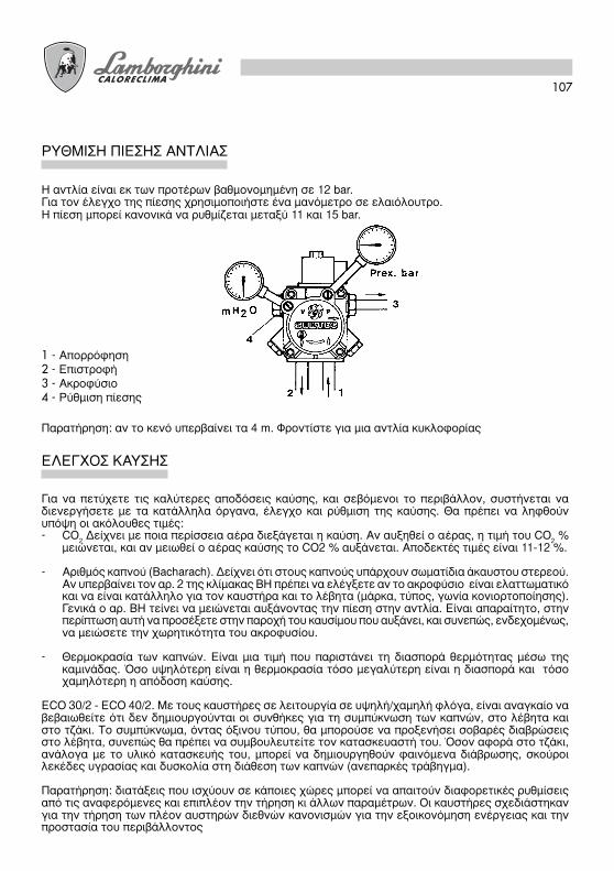
107
∏ ·ÓÙÏ›· Â›Ó·È ÂÎ ÙˆÓ ÚÔÙ¤ÚˆÓ ‚·ıÌÔÓÔÌË̤ÓË Û 12 bar.°È· ÙÔÓ ¤ÏÂÁ¯Ô Ù˘ ›ÂÛ˘ ¯ÚËÛÈÌÔÔÈ‹ÛÙ ¤Ó· Ì·ÓfiÌÂÙÚÔ Û ÂÏ·ÈfiÏÔ˘ÙÚÔ.∏ ›ÂÛË ÌÔÚ› ηÓÔÓÈο Ó· Ú˘ıÌ›˙ÂÙ·È ÌÂٷ͇ 11 Î·È 15 bar.
ƒÀ£ªπ™∏ ¶π∂™∏™ ∞¡∆§π∞™
1 - ∞ÔÚÚfiÊËÛË2 - ∂ÈÛÙÚÔÊ‹3 - ∞ÎÚÔʇÛÈÔ4 - ƒ‡ıÌÈÛË ›ÂÛ˘
¶·Ú·Ù‹ÚËÛË: ·Ó ÙÔ ÎÂÓfi ˘ÂÚ‚·›ÓÂÈ Ù· 4 m. ºÚÔÓÙ›ÛÙ ÁÈ· ÌÈ· ·ÓÙÏ›· ΢ÎÏÔÊÔÚ›·˜
°È· Ó· ÂÙ‡¯ÂÙ ÙȘ ηχÙÂÚ˜ ·Ô‰fiÛÂȘ η‡Û˘, Î·È Û‚fiÌÂÓÔÈ ÙÔ ÂÚÈ‚¿ÏÏÔÓ, Û˘ÛÙ‹ÓÂÙ·È Ó·‰ÈÂÓÂÚÁ‹ÛÂÙ Ì ٷ ηٿÏÏËÏ· fiÚÁ·Ó·, ¤ÏÂÁ¯Ô Î·È Ú‡ıÌÈÛË Ù˘ η‡Û˘. £· Ú¤ÂÈ Ó· ÏËÊıÔ‡Ó˘fi„Ë ÔÈ ·ÎfiÏÔ˘ı˜ ÙÈ̤˜:- CO
2 ¢Â›¯ÓÂÈ Ì ÔÈ· ÂÚ›ÛÛÂÈ· ·¤Ú· ‰ÈÂÍ¿ÁÂÙ·È Ë Î·‡ÛË. ∞Ó ·˘ÍËı› Ô ·¤Ú·˜, Ë ÙÈÌ‹ ÙÔ˘ CO
2 %
ÌÂÈÒÓÂÙ·È, Î·È ·Ó ÌÂȈı› Ô ·¤Ú·˜ η‡Û˘ ÙÔ CO2 % ·˘Í¿ÓÂÙ·È. ∞Ô‰ÂÎÙ¤˜ ÙÈ̤˜ Â›Ó·È 11-12 %.
- ∞ÚÈıÌfi˜ ηÓÔ‡ (Bacharach). ¢Â›¯ÓÂÈ fiÙÈ ÛÙÔ˘˜ ηÓÔ‡˜ ̆ ¿Ú¯Ô˘Ó ۈ̷ٛ‰È· ¿Î·˘ÛÙÔ˘ ÛÙÂÚÂÔ‡.∞Ó ̆ ÂÚ‚·›ÓÂÈ ÙÔÓ ·Ú. 2 Ù˘ Îϛ̷η˜ BH Ú¤ÂÈ Ó· ÂϤÁÍÂÙ ·Ó ÙÔ ·ÎÚÔʇÛÈÔ Â›Ó·È ÂÏ·Ùو̷ÙÈÎfiÎ·È Ó· Â›Ó·È Î·Ù¿ÏÏËÏÔ ÁÈ· ÙÔÓ Î·˘ÛÙ‹Ú· Î·È ÙÔ Ï¤‚ËÙ· (Ì¿Úη, Ù‡Ô˜, ÁˆÓ›· ÎÔÓÈÔÚÙÔÔ›ËÛ˘).°ÂÓÈο Ô ·Ú. BH Ù›ÓÂÈ Ó· ÌÂÈÒÓÂÙ·È ·˘Í¿ÓÔÓÙ·˜ ÙËÓ ›ÂÛË ÛÙËÓ ·ÓÙÏ›·. ∂›Ó·È ··Ú·›ÙËÙÔ, ÛÙËÓÂÚ›ÙˆÛË ·˘Ù‹ Ó· ÚÔÛ¤ÍÂÙ ÛÙËÓ ·ÚÔ¯‹ ÙÔ˘ η˘Û›ÌÔ˘ Ô˘ ·˘Í¿ÓÂÈ, Î·È Û˘ÓÂÒ˜, ÂӉ¯Ô̤ӈ˜,Ó· ÌÂÈÒÛÂÙ ÙËÓ ¯ˆÚËÙÈÎfiÙËÙ· ÙÔ˘ ·ÎÚÔÊ˘Û›Ô˘.
- £ÂÚÌÔÎÚ·Û›· ÙˆÓ Î·ÓÒÓ. ∂›Ó·È ÌÈ· ÙÈÌ‹ Ô˘ ·ÚÈÛÙ¿ÓÂÈ ÙË ‰È·ÛÔÚ¿ ıÂÚÌfiÙËÙ·˜ ̤ۈ Ù˘ηÌÈÓ¿‰·˜. ŸÛÔ ˘„ËÏfiÙÂÚË Â›Ó·È Ë ıÂÚÌÔÎÚ·Û›· ÙfiÛÔ ÌÂÁ·Ï‡ÙÂÚË Â›Ó·È Ë ‰È·ÛÔÚ¿ Î·È ÙfiÛÔ¯·ÌËÏfiÙÂÚË Ë ·fi‰ÔÛË Î·‡Û˘.
ECO 30/2 - ECO 40/2. ªÂ ÙÔ˘˜ η˘ÛÙ‹Ú˜ Û ÏÂÈÙÔ˘ÚÁ›· Û ˘„ËÏ‹/¯·ÌËÏ‹ ÊÏfiÁ·, Â›Ó·È ·Ó·Áη›Ô Ó·‚‚·Èˆı›Ù fiÙÈ ‰ÂÓ ‰ËÌÈÔ˘ÚÁÔ‡ÓÙ·È ÔÈ Û˘Óı‹Î˜ ÁÈ· ÙË Û˘Ì‡ÎÓˆÛË ÙˆÓ Î·ÓÒÓ, ÛÙÔ Ï¤‚ËÙ· ηÈÛÙÔ Ù˙¿ÎÈ. ∆Ô Û˘Ì‡Îӈ̷, fiÓÙ·˜ fiÍÈÓÔ˘ Ù‡Ô˘, ı· ÌÔÚÔ‡Û ӷ ÚÔÍÂÓ‹ÛÂÈ ÛÔ‚·Ú¤˜ ‰È·‚ÚÒÛÂȘÛÙÔ Ï¤‚ËÙ·, Û˘ÓÂÒ˜ ı· Ú¤ÂÈ Ó· Û˘Ì‚Ô˘Ï¢Ù›Ù ÙÔÓ Î·Ù·Û΢·ÛÙ‹ ÙÔ˘. ŸÛÔÓ ·ÊÔÚ¿ ÛÙÔ Ù˙¿ÎÈ,·Ó¿ÏÔÁ· Ì ÙÔ ˘ÏÈÎfi ηٷÛ΢‹˜ ÙÔ˘, ÌÔÚ› Ó· ‰ËÌÈÔ˘ÚÁËıÔ‡Ó Ê·ÈÓfiÌÂÓ· ‰È¿‚ÚˆÛ˘, ÛÎÔ‡ÚÔÈÏÂΤ‰Â˜ ˘ÁÚ·Û›·˜ Î·È ‰˘ÛÎÔÏ›· ÛÙË ‰È¿ıÂÛË ÙˆÓ Î·ÓÒÓ (·Ó·ÚΤ˜ ÙÚ¿‚ËÁÌ·).
¶·Ú·Ù‹ÚËÛË: ‰È·Ù¿ÍÂȘ Ô˘ ÈÛ¯‡Ô˘Ó Û οÔȘ ¯ÒÚ˜ ÌÔÚ› Ó· ··ÈÙÔ‡Ó ‰È·ÊÔÚÂÙÈΤ˜ Ú˘ıÌ›ÛÂȘ·fi ÙȘ ·Ó·ÊÂÚfiÌÂÓ˜ Î·È ÂÈϤÔÓ ÙËÓ Ù‹ÚËÛË ÎÈ ¿ÏÏˆÓ ·Ú·Ì¤ÙÚˆÓ. √È Î·˘ÛÙ‹Ú˜ ۯ‰ȿÛÙËηÓÁÈ· ÙËÓ Ù‹ÚËÛË ÙˆÓ Ï¤ÔÓ ·˘ÛÙËÚÒÓ ‰ÈÂıÓÒÓ Î·ÓÔÓÈÛÌÒÓ ÁÈ· ÙËÓ ÂÍÔÈÎÔÓfiÌËÛË ÂÓ¤ÚÁÂÈ·˜ Î·È ÙËÓÚÔÛÙ·Û›· ÙÔ˘ ÂÚÈ‚¿ÏÏÔÓÙÔ˜
∂§∂°Ã√™ ∫∞À™∏™

108
ŸÏ˜ ÔÈ ÂÚÁ·Û›Â˜ Ú¤ÂÈ Ó· ‰ÈÂÓÂÚÁÔ‡ÓÙ·È ·ÊÔ‡ ¤¯ÂÈ ‰È·ÎÔ› Ë ·ÚÔ¯‹ ËÏÂÎÙÚÈÎÔ‡ Ú‡̷ÙÔ˜.∞Ê·ÈÚÒÓÙ·˜ ÙÔ Î·fi ÌÔÚ›Ù ӷ ‰ÈÂÓÂÚÁ‹ÛÂÙ ÙÔÓ Î·ı·ÚÈÛÌfi Ù˘ ʈÙÔ·ÓÙ›ÛÙ·Û˘, Ó· ÂÈıˆڋÛÂÙÂÙÔÓ ÎÈÓËÙ‹Ú·, ÙËÓ ËÏÂÎÙÚÔÌ·ÁÓËÙÈ΋ ‚·Ï‚›‰·, ÙÔ ÌÂÙ·Û¯ËÌ·ÙÈÛÙ‹ Î·È ÙÔ ÛÂÚ‚Ô¯ÂÈÚÈÛÙ‹ÚÈÔ ÙÔ˘ÎÏ›ÛÙÚÔ˘ ·¤Ú·. °È· Ó· ¤¯ÂÙ ÚfiÛ‚·ÛË ÛÙÔÓ ·ÓÂÌÈÛÙ‹Ú· Î·È ÛÙÔ ÎÏ›ÛÙÚÔ ·¤Ú· Ú¤ÂÈ Ó· ‚Á¿ÏÂÙÂÙË ÌÔÓ¿‰· Ͽη˜ Î·È ÂΛÓË Ô˘ ʤÚÂÈ Ù· ÂÍ·ÚÙ‹Ì·Ù·, Ô˘ Â›Ó·È Á·ÓÙ˙ˆÌ¤ÓË ÛÙËÓ ÚÔ‚ÏÂfiÌÂÓËı¤ÛË. ∏ ÂÚÁ·Û›· ·˘Ù‹ ηıÈÛÙ¿ ÙÂÏ›ˆ˜ ÚÔÛ‚¿ÛÈÌË Î·È ÙËÓ ÎÂÊ·Ï‹.°È· ÙË ‰ÈÂÓ¤ÚÁÂÈ· ÙÔ˘ ηı·ÚÈÛÌÔ‡/ÂÈıÂÒÚËÛ˘ ·ÎÚÔÊ˘Û›Ô˘- ËÏÂÎÙÚÔ‰›ˆÓ, Û˘Ó‹ıˆ˜ ·Ê·ÈÚÂ›Ù·È ËÌÔÓ¿‰· ÎÂÊ·Ï‹˜ ̤ۈ Ù˘ ·ÔÌ¿ÎÚ˘ÓÛ˘ Ù˘ ¿ӈ Ͽη˜.
™À¡∆∏ƒ∏™∏
∆Ú·‚‹ÍÙ ÙË ·fi ÙËÓ ¤‰Ú· Ù˘ Î·È Î·ı·Ú›ÛÙ ÙÔ Â˘·›ÛıËÙÔ ÙÌ‹Ì· Ù˘ Ì ¤Ó· ÛÙÂÁÓfi ·Ó›.
ºø∆√∞¡∆π™∆∞™∏
∫Ï›ÛÙ ÙË ı˘Ú›‰· ÛÙËÓ ·ÔÚÚfiÊËÛË, ÍÂÌÔÓÙ¿ÚÂÙ ÙÔ Î·¿ÎÈ Ù˘ ·ÓÙÏ›·˜, ‚Á¿ÏÙ ÙÔ ‰ÈÎÙ˘ˆÙfi Ê˘Û›ÁÁÈÔ,χÓÂÙ¤ ÙÔ Ì ‚ÂÓ˙›ÓË Î·È Í‚Á¿ÏÙ ÙÔ Ì ÂÙڤϷÈÔ. •·Ó·ÌÔÓÙ¿ÚÂÙ¤ Ù· fiÏ· ÂÈÌÂÏÒ˜.
ºπ§∆ƒ√ ∞¡∆§π∞™
∫Ï›ÛÙ ÙË ı˘Ú›‰· ÛÙËÓ ·ÔÚÚfiÊËÛË, ÍÂÌÔÓÙ¿ÚÂÙ ÙË ı‹ÎË Ê›ÏÙÚÔ˘, Ô˘ Â›Ó·È Û˘Ó‹ıˆ˜ ‚ȉˆÌ¤ÓË ÛÙÔÛÒÌ· Ê›ÏÙÚÔ˘ Î·È ÚÔ¯ˆÚ‹ÛÙ Û ÂÈÌÂÏ‹ ηı·ÚÈÛÌfi ÙÔ˘ ‰ÈÎÙ˘ˆÙÔ‡ ÊÈÏÙÚ·Ú›ÛÌ·ÙÔ˜. •·Ó·ÌÔÓÙ¿ÚÂ٤ٷ fiÏ· ÂÈÌÂÏÒ˜.
ºπ§∆ƒ√ °ƒ∞ªª∏™
°È· ÚfiÛ‚·ÛË ÛÙ· ·ÚÈ· ÂÍ·ÚÙ‹Ì·Ù· ·ÚΛ Ó· ‚Á¿ÏÂÙ ÙÔ Î·fi.∏ Û˘ÓÙ‹ÚËÛË ÛÙËÓ ÎÂÊ·Ï‹ η‡Û˘ ‰ÈÂÓÂÚÁÂ›Ù·È Ì ÙÔÓ ·ÎfiÏÔ˘ıÔ ÙÚfiÔ:
● •Â‚ȉÒÛÙ ÙË ‚›‰· Î·È ‚Á¿ÏÙ ÙÔ Î·fi.● •Â‚ȉÒÛÙ ÙȘ ‚›‰Â˜ Ù˘ ¿ӈ Ͽη˜ Î·È Á·ÓÙ˙ÒÛÙ ÙȘ ÛÙË ı¤ÛË ˘ËÚÂÛ›·˜.● °È· ÚfiÛ‚·ÛË ÛÙÔÓ ·ÓÂÌÈÛÙ‹Ú· Í‚ȉÒÛÙ ÙȘ ‚›‰Â˜ Ù˘ οو Ͽη˜ ·ÔÛ˘Ó‰¤ÔÓÙ·˜ Ù· ÊȘ ÙÔ˘
ËÏÂÎÙÚÈÎÔ‡ ›Ó·Î·.
∞¡∂ªπ™∆∏ƒ∞™ ∫§∂π™∆ƒ√À ∞∂ƒ∞

109
∞ÊÔ‡ ∞Ê·ÈÚ¤ÛÂÙ ÙÔ Î·fi, ÙÚ·‚‹ÍÙ ٷ ηÏ҉ȷ ˘„ËÏ‹˜ Ù¿Û˘ ·fi ÙÔ Ï¢Úfi ÙÔ˘ÌÂÙ·Û¯ËÌ·ÙÈÛÙ‹, ÙÚ·‚‹ÍÙ ÙËÓ ÊˆÙÔ·ÓÙ›ÛÙ·ÛË 1, Í‚ȉÒÛÙ ÙÔ Ú·ÎfiÚ 2 Ô˘ Û˘Ó‰¤ÂÈ ÙÔ ÛˆÏËÓ›ÛÎÔÙÔ˘ ÂÙÚÂÏ·›Ô˘ ÛÙË ÁÚ·ÌÌ‹ 3 ÙÔ˘ ·ÎÚÔÊ˘Û›Ô˘ (Ù· Ú·ÎfiÚ Â›Ó·È 2 ÁÈ· ECO 30/2 - ECO40/2), ÍÂÛÊ›ÍÙÂÙȘ ‚›‰Â˜ 4 Î·È ÛÙÚ¤ÊÔÓÙ·˜ ÙË ÊÏ¿ÓÙ˙· ·ÚÈÛÙÂÚfiÛÙÚÔÊ· ‚Á¿ÏÙ ÙË ÌÔÓ¿‰· ÊÏ¿ÓÙ˙·˜-·ÎÚÔÊ˘Û›Ô˘-ÂÎÙÚÔ¤·-ËÏÂÎÙÚÔ‰›ˆÓ.
•Â‚ȉÒÛÙ ÙȘ ‚›‰Â˜ 5, ÁÈ· Ó· ‚Á¿ÏÂÙ ÙÔÓ ÂÎÙÚÔ¤· Î·È ÙË ‚›‰· 6 ÁÈ· Ó· ·Ê·ÈÚ¤ÛÂÙ ٷ ËÏÂÎÙÚfi‰È·.ŒÓ·˜ ηÏfi˜ ηı·ÚÈÛÌfi˜ ÙÔ˘ ·ÎÚÔÊ˘Û›Ô˘ ÂÈÙ˘Á¯¿ÓÂÙ·È ÍÂÌÔÓÙ¿ÚÔÓÙ·˜ ÙÔ Ê›ÏÙÚÔ Î·È Î·ı·Ú›˙ÔÓÙ·˜ÙȘ ÂÁÎÔ¤˜ Î·È ÙËÓ Ô‹ ÎÔÓÈÔÚÙÔÔ›ËÛ˘, Ì ‚ÂÓ˙›ÓË Î·È ÍÂϤÓÔÓÙ·˜ Ì ÂÙڤϷÈÔ.•·Ó·ÌÔÓÙ¿ÚÔÓÙ¿˜ Ù· fiÏ·, Ó· ÚÔÛ¤ÍÂÙ ÛÙË ÛˆÛÙ‹ ÙÔÔı¤ÙËÛË ÙˆÓ ËÏÂÎÙÚÔ‰›ˆÓ-ÂÎÙÚÔ¤·.
∏§∂∫∆ƒ√¢π∞ – ∞∫ƒ√ºÀ™π√
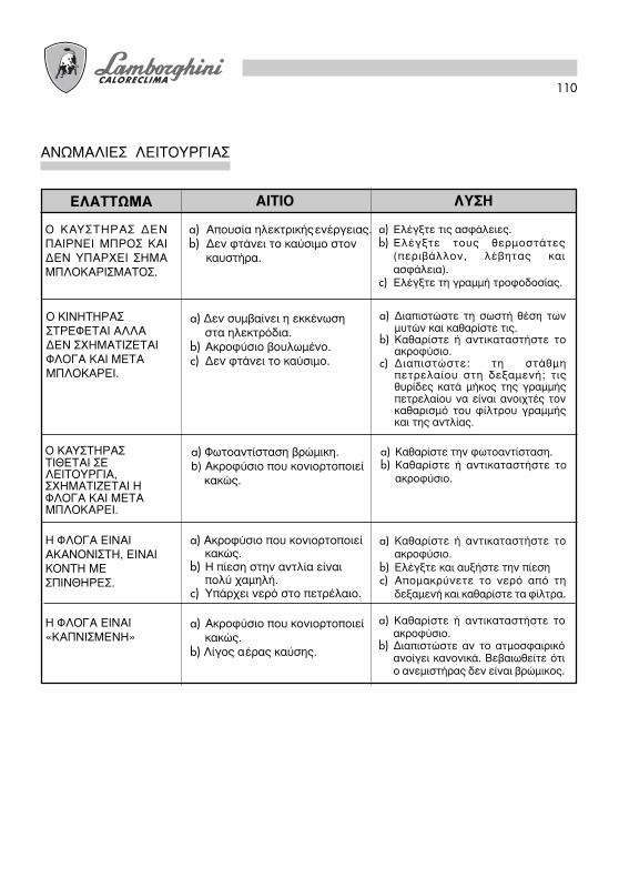
110
∞¡øª∞§π∂™ §∂π∆√Àƒ°π∞™
§À™∏∞π∆π√∂§∞∆∆øª∞
a) ∂ϤÁÍÙ ÙȘ ·ÛÊ¿ÏÂȘ.b) ∂ϤÁÍÙ ÙÔ˘˜ ıÂÚÌÔÛٿ٘
(ÂÚÈ‚¿ÏÏÔÓ, Ϥ‚ËÙ·˜ ηȷÛÊ¿ÏÂÈ·).
c) ∂ϤÁÍÙ ÙË ÁÚ·ÌÌ‹ ÙÚÔÊÔ‰ÔÛ›·˜.
√ ∫∞À™∆∏ƒ∞™ ¢∂¡¶∞πƒ¡∂𠪶ƒ√™ ∫∞π¢∂¡ À¶∞ƒÃ∂π ™∏ª∞ª¶§√∫∞ƒπ™ª∞∆√™.
a) ¢È·ÈÛÙÒÛÙ ÙË ÛˆÛÙ‹ ı¤ÛË ÙˆÓÌ˘ÙÒÓ Î·È Î·ı·Ú›ÛÙ ÙȘ.
b) ∫·ı·Ú›ÛÙ ‹ ·ÓÙÈηٷÛÙ‹ÛÙ ÙÔ·ÎÚÔʇÛÈÔ.
c) ¢È·ÈÛÙÒÛÙÂ: ÙË ÛÙ¿ıÌËÂÙÚÂÏ·›Ô˘ ÛÙË ‰ÂÍ·ÌÂÓ‹; ÙȘı˘Ú›‰Â˜ ηٿ Ì‹ÎÔ˜ Ù˘ ÁÚ·ÌÌ‹˜ÂÙÚÂÏ·›Ô˘ Ó· Â›Ó·È ·ÓÔȯ٤˜ ÙÔÓηı·ÚÈÛÌfi ÙÔ˘ Ê›ÏÙÚÔ˘ ÁÚ·ÌÌ‹˜Î·È Ù˘ ·ÓÙÏ›·˜.
√ ∫π¡∏∆∏ƒ∞™™∆ƒ∂º∂∆∞π ∞§§∞¢∂¡ ™Ã∏ª∞∆π∑∂∆∞πº§√°∞ ∫∞π ª∂∆∞ª¶§√∫∞ƒ∂π.
a) ∫·ı·Ú›ÛÙ ÙËÓ ÊˆÙÔ·ÓÙ›ÛÙ·ÛË.b) ∫·ı·Ú›ÛÙ ‹ ·ÓÙÈηٷÛÙ‹ÛÙ ÙÔ
·ÎÚÔʇÛÈÔ.
√ ∫∞À™∆∏ƒ∞™∆π£∂∆∞π ™∂§∂π∆√Àƒ°π∞,™Ã∏ª∞∆π∑∂∆∞π ∏º§√°∞ ∫∞π ª∂∆∞ª¶§√∫∞ƒ∂π.
a) ∞Ô˘Û›· ËÏÂÎÙÚÈ΋˜ÂÓ¤ÚÁÂÈ·˜.b) ¢ÂÓ ÊÙ¿ÓÂÈ ÙÔ Î·‡ÛÈÌÔ ÛÙÔÓ
η˘ÛÙ‹Ú·.
a) ¢ÂÓ Û˘Ì‚·›ÓÂÈ Ë ÂÎΤӈÛËÛÙ· ËÏÂÎÙÚfi‰È·.
b) ∞ÎÚÔʇÛÈÔ ‚Ô˘ÏˆÌ¤ÓÔ.c) ¢ÂÓ ÊÙ¿ÓÂÈ ÙÔ Î·‡ÛÈÌÔ.
a) ºˆÙÔ·ÓÙ›ÛÙ·ÛË ‚ÚÒÌÈÎË.b) ∞ÎÚÔʇÛÈÔ Ô˘ ÎÔÓÈÔÚÙÔÔÈ› ηÎÒ˜.
∏ º§√°∞ ∂π¡∞π∞∫∞¡√¡π™∆∏, ∂π¡∞π∫√¡∆∏ ª∂™¶π¡£∏ƒ∂™.
∏ º§√°∞ ∂π¡∞π«∫∞¶¡π™ª∂¡∏»
a) ∞ÎÚÔʇÛÈÔ Ô˘ ÎÔÓÈÔÚÙÔÔÈ›ηÎÒ˜.
b) ∏ ›ÂÛË ÛÙËÓ ·ÓÙÏ›· ›ӷÈÔχ ¯·ÌËÏ‹.
c) À¿Ú¯ÂÈ ÓÂÚfi ÛÙÔ ÂÙڤϷÈÔ.
a) ∞ÎÚÔʇÛÈÔ Ô˘ ÎÔÓÈÔÚÙÔÔÈ›ηÎÒ˜.
b) §›ÁÔ˜ ·¤Ú·˜ η‡Û˘.
a) ∫·ı·Ú›ÛÙ ‹ ·ÓÙÈηٷÛÙ‹ÛÙ ÙÔ·ÎÚÔʇÛÈÔ.
b) ∂ϤÁÍÙÂ Î·È ·˘Í‹ÛÙ ÙËÓ ›ÂÛËc) ∞ÔÌ·ÎÚ‡ÓÂÙ ÙÔ ÓÂÚfi ·fi ÙË
‰ÂÍ·ÌÂÓ‹ Î·È Î·ı·Ú›ÛÙ ٷ Ê›ÏÙÚ·.
a) ∫·ı·Ú›ÛÙ ‹ ·ÓÙÈηٷÛÙ‹ÛÙ ÙÔ·ÎÚÔʇÛÈÔ.
b) ¢È·ÈÛÙÒÛÙ ·Ó ÙÔ ·ÙÌÔÛÊ·ÈÚÈÎfi·ÓÔ›ÁÂÈ Î·ÓÔÓÈο. µÂ‚·Èˆı›Ù fiÙÈÔ ·ÓÂÌÈÛÙ‹Ú·˜ ‰ÂÓ Â›Ó·È ‚ÚÒÌÈÎÔ˜.


BRUCIATORICALDAIE MURALI E TERRA A GAS
GRUPPI TERMICI IN GHISA E IN ACCIAIOGENERATORI DI ARIA CALDA
TRATTAMENTO ACQUACONDIZIONAMENTO
04/2006Cod. 97.00236.0/2
LAMBORGHINI CALOR S.p.A.VIA STATALE, 342
44040 DOSSO (FERRARA) ITALIA
TEL. ITALIA 0532/359811 - EXPORT 0532/359913FAX ITALIA 0532/359952 - EXPORT 0532/359947
0444
352
000
-VI