ASSOCIAZIONE NAZIONALE MECCANICA TEORICA E … · ASSOCIAZIONE NAZIONALE MECCANICA TEORICA E...
170
ASSOCIAZIONE NAZIONALE MECCANICA TEORICA E APPLICATA RACCOLTA DEI SOMMARI XX Convegno Nazionale di Meccanica Computazionale VII Riunione del Gruppo Materiali AIMETA a cura di Elio Sacco - Sonia Marfia UNIVERSITA’ DEGLI STUDI DI CASSINO E DEL LAZIO MERIDIONALE DIPARTIMENTO DI INGEGNERIA CIVILE E MECCANICA Cassino 11 – 13 giugno 2014 www.gimc-gma2014.dicam.unibo.it
Transcript of ASSOCIAZIONE NAZIONALE MECCANICA TEORICA E … · ASSOCIAZIONE NAZIONALE MECCANICA TEORICA E...
ASSOCIAZIONE NAZIONALE MECCANICA
TEORICA E APPLICATA
RACCOLTA DEI SOMMARI
XX Convegno Nazionale di Meccanica Computazionale
VII Riunione del Gruppo Materiali AIMETA
a cura di Elio Sacco - Sonia Marfia
UNIVERSITA’ DEGLI STUDI DI CASSINO E DEL LAZIO MERIDIONALE
DIPARTIMENTO DI INGEGNERIA CIVILE E MECCANICA
Cassino 11 – 13 giugno 2014
www.gimc-gma2014.dicam.unibo.it


i
Indice dei sommari
GIMC Error Sensitivity to Refinement: a criterion for optimal grid adaptation Paolo Luchini, Flavio Giannetti 3
Isogeometric treatment of large deformation contact and debonding problems with NURBS and T-Splines Rossana Dimitri 5
Pseudopotentials and thermomechanical response of materials and structures: a convex analysis approach Michele Marino 7
Multiphase modeling of porous media: from concrete to tumor growth Giuseppe Sciumè 9
On the accuracy of the nodal elastic stress of zero thickness interface elements Giovanni Castellazzi, Daniela Ciancio, Francesco Ubertini 11
The strong formulation finite element method: stability and accuracy Francesco Tornabene, Nicholas Fantuzzi, Michele Bacciocchi 12
Mixed methods for viscoelastodynamics and topology optimization Giacomo Maurelli, Nadia Maini, Paolo Venini, 13
Dissipation-based integration algorithm for SMA constitutive models Edoardo Artioli, Paolo Bisegna 14
Parallel programming techniques for the computation of basins of attraction Pierpaolo Belardinelli, Stefano Lenci 16
Limit analysis on FRP-strengthened RC members Dario De Domenico, Aurora A. Pisano, Paolo Fuschi 18
Integrated structure for a resonant micro-gyroscope and accelerometer Valentina Zega, Claudia Comi, Alberto Corigliano, Carlo Valzasina 20
Numerical analyses in the nonlinear dynamics and control of microcantilevers in atomic force microscopy Valeria Settimi, Giuseppe Rega 22
Buckling analysis using a generalized beam model including section distortions Andrea Genoese, Alessandra Genoese, Antonio Bilotta, Giovanni Garcea 24
Shakedown analysis of 3D frames with an effective evaluation of the elastic domain and of the load combinations Leonardo Leonetti, Antonio Bilotta, Giovanni Garcea, Raffaele Casciaro 26
A simple beam model to assess the strength of adhesively bonded tile floorings Stefano de Miranda, Antonio Palermo, Francesco Ubertini 28
Concrete mechanics at early age Giuseppe Sciumè, Farid Benboudjema, Giorgio Zavarise 30
Rigid wedge-shaped hull impacting a free surface: a lattice Boltzmann-immersed boundary study C. Burrafato, S. de Miranda, A. De Rosis, F. Ubertini 32

ii
Analytical evaluation of displacement and stress fields induced in elastic half-spaces by linear distributions of pressure on the surface Francesco Marmo, Luciano Rosati 33
How to refine the Sardinia Radio Telescope finite element model Antonio Cazzani, Flavio Stochino, Emilio Turco 35
A GBT finite element based on elastic solution S. de Miranda, A. Madeo, D. Melchionda, F. Ubertini 37
Ceramic sanitary wares: reverse engineering strategy for mould prototyping S. de Miranda, L. Patruno, M. Ricci, R. Saponelli, F. Ubertini 38
Computational modeling of fiber recruitment for statistical distributed biological tissues Alessio Gizzi, Marcello Vasta, Anna Pandolfi 40
A method of cells-type kinematic limit analysis approach for the evaluation of the macroscopic strength domain of in-plane loaded periodic masonry Gabriele Milani, Alberto Taliercio 42
A simple FEM model to predict the mechanical behaviour of an equiatomic NiTi SMA alloy Vittorio Di Cocco, Francesco Iacoviello, Alessandra Rossi 43
Evaluation of performance of cold-formed steel structures using Koiter asymptotic approach A. Madeo, R. Casciaro, G. Zagari, R. Zinno, G. Zucco 45
A finite-element approach for the analysis of pin-bearing failure of composite laminates Michele Marino, Francesca Nerilli, Giuseppe Vairo 46
Advanced numerical simulations in biomechanics: patient-specific finite element analysis of transcatheter aortic valve implantation S. Morganti, M. Conti, M. Aiello, A. Reali, F. Auricchio 48
A numerically efficient implicit integration algorithm for the Matsuoka-Nakai failure criterion Andrea Panteghini, Rocco Lagioia 50
Selective mass scaling for thin structures discretized with multi-layered, solid-shell elements Federica Confalonieri, Umberto Perego, Aldo Ghisi 51
A generalized time-domain approach for motion-related wind loads on long-span bridges S. de Miranda, L. Patruno, F. Ubertini, G. Vairo 53
A new flexible approach for shape memory alloy constitutive modeling Ferdinando Auricchio, Elena Bonetti, Giulia Scalet, Francesco Ubertini 55
Damage modelling in concrete subject to sulfate attack Nicola Cefis, Claudia Comi 57
A 3D mixed frame element with multi-axial coupling for thin-walled structures with damage Daniela Addessi, Paolo Di Re 59
A basic introduction to isogeometric collocation methods with some applications Alessandro Reali, Ferdinando Auricchio, Lourenco Beirão da Veiga, Hector Gomez, Thomas JR Hughes, Giancarlo Sangalli 60

iii
On the state update for isotropic elasto-plastic hardening materials: a dissipation-based algorithm Nicola A. Nodargi, Edoardo Artioli, Federica Caselli, Paolo Bisegna 62
A Lagrangian finite element approach for the numerical simulation of landslide runouts Massimiliano Cremonesi, Francesco Ferri, Umberto Perego 64
Geometry of elastoplasticity in the nonlinear range Giovanni Romano, Raffaele Barretta, Marina Diaco 66
FE-Meshless multiscale non-linear analysis of masonry structures Giuseppe Giambanco , Emma La Malfa Ribolla, Antonino Spada 67
Non-linear analysis of 3D elastoplastic framed structures Valerio Carollo, Giuseppe Giambanco, Antonino Spada 69
Interface poroelastic laws to model fluid-induced damage in oil wells Carlo Callari, Valentina Fasano 71
Formulation of rate-dependent cohesive-zone models Giulio Alfano, Marco Musto 72
Porous shape memory alloys: a micromechanical analysis V. Sepe , F. Auricchio, S. Marfia, E. Sacco 74
A corotational tetrahedral element with rotational degrees of freedom for large-displacement analysis of inelastic structures Paolo Bisegna, Federica Caselli, Edoardo Artioli, Nicola A. Nodargi 76
A consistency study of cohesive zone models for mixed-mode debonding problems Rossana Dimitri, Marco Trullo, Laura De Lorenzis, Giorgio Zavarise 78
A multilevel finite element approach for piezoelectric textiles made of polymeric nanofibers Claudio Maruccio, Laura De Lorenzis 80
Computational issues on multiscale FE analysis Francesco Parrinello, Guido Borino 82
An efficient Bouc & Wen approach for seismic analysis of masonry tower Luca Facchini, Michele Betti 84
Analysis of masonry arches: a NURBS based simple applicative program Andrea Chiozzi, Marcello Malagù, Antonio Tralli, Antonio Cazzani 85
Isogeometric collocation for large-deformation frictional contact Laura De Lorenzis, Roland Kruse, Nhon Nguyen-Thanh 87
An adaptive multiscale approach for the failure analysis of fiber-reinforced composite materials Domenico Bruno, Fabrizio Greco, Lorenzo Leonetti, Stefania Lo Feudo, Paolo Lonetti 89
Consistent tangent operator for an exact Kirchhoff rod model Leopoldo Greco, Massimo Cuomo 91
An implicit G1-continuity interpolation for Kirchhoff plate elements Leopoldo Greco, Massimo Cuomo 92
Pull-out strength of chemical anchors in natural stone Loredana Contrafatto, Renato Cosenza 93
Strain gradient elasticity within the symmetric BEM formulation S. Terravecchia, T. Panzeca, C. Polizzotto 95

iv
Multidomain Symmetric Galerkin BEM for non-linear analysis of masonries in-plane loaded L. Zito, S. Terravecchia, T. Panzeca 97
GMA Sorption of low molecular weight compounds in polymers: thermodynamic issues and plasticization effects Giuseppe Mensitieri, Giuseppe Scherillo, Pellegrino Musto 101
Propagation of elastic waves and generation of band-gaps in diffusively damaged structures Giorgio Carta, Michele Brun, Alexander B. Movchan 103
On the compressive strength of glass-microballoons/thermoset-matrix syntactic foams Lorenzo Bardella, Andrea Panteghini 105
Elastically deformable scale through configurational forces Francesco Dal Corso, Davide Bigoni, Federico Bosi, Diego Misseroni 106
Flaw-tolerance of nonlocal discrete systems and interpretation according to network theory Andrea Infuso, Marco Paggi 107
A model to interpret the wedge-shaped spalling in pull-out tests of FRP from concrete Roberto Ballarini, Annalisa Franco, Gianni Royer Carfagni 108
Morphoelastic rods Alessandro Tiero, Giuseppe Tomassetti 110
Bending of shape-memory alloys’ beams: constitutive modeling and structural response Silvia Di Caprera, Michele Marino, Giuseppe Vairo 111
Pre-buckling behavior of composite beams: an innovative approach Francesco Ascione, Geminiano Mancusi, Marco Lamberti 113
Effective modeling of multilayered composites with cohesive and imperfect interfaces Roberta Massabò, Francesca Campi 115
Micropolar and second-gradient homogenization of chiral cellular solids Andrea Bacigalupo, Luigi Gambarotta 117
TWSME of NiTi strips in free bending conditions: experimental and theoretical approach A. Fortini, M. Merlin, R. Rizzoni, S. Marfia 119
Discrete-to-continuum approaches for complex materials as ‘Non–Simple’ continua Patrizia Trovalusci 121
Constitutive Behavior of FRCM Materials for Structural Plating: an experimental study Luigi Ascione, Anna D’Aponte, Geminiano Mancusi 123
A new auxetic lattice model Luigi Cabras, Michele Brun 125
Cloaking in flexural waves D. Colquitt, M. Brun, M. Gei, A.B. Movchan, N.V. Mochan, I.S. Jones 126
A contact problem in couple-stress thermoelasticity Thanasis Zisis, Francesco Dal Corso 127
Flutter analysis of piezoelectric laminate beams in MEMS Raffaele Ardito, Rocco Musci 128

v
Variational approach to damage mechanics with plasticity and nucleation of cohesive cracks Roberto Alessi, Achille Paolone, Stefano Vidoli 130
Geometric numerical integrators based on the magnus expansion in bifurcation problems for non-linear elastic solids Anna Castellano, Pilade Foti, Aguinaldo Fraddosio, Salvatore Marzano, Mario Daniele Piccioni 132
Experimental and numerical approaches for the ultrasonic characterization of composite materials Anna Castellano, Pilade Foti, Aguinaldo Fraddosio, Salvatore Marzano, Mario Daniele Piccioni 134
A micromechanical four-phase model to predict the compressive failure surface of cement concrete Andrea Caporale, Raimondo Luciano 136
Multiscale analyses of a three layers osteochondral scaffold G. Parisi, S. Bignozzi, E. Kon, P. Vena 138
Damage propagation modeling of masonry structures subjected to dynamic loading Jessica Toti, Vincenzo Gattulli, Elio Sacco 140
A micromechanical approach for the micropolar modeling of heterogeneous periodic media Maria Laura De Bellis, Daniela Addessi, Elio Sacco 142
An experimental investigation on the axial and rotational behavior of web-flange junctions of open-web pultruded glass fibre-reinforced profiles Luciano Feo, Ayman S. Mosallam, Rosa Penna 144
Development of biodegradable magnesium alloy stents with coating: the peeling problem Lorenza Petrini,Wei Wu, Lina Altomare, Barbara Previtali, Maurizio Vedani, Francesco Migliavacca 146
Interface constitutive relation derived from a representative adhesive layer Guido Borino , Francesco Parrinello 148
A cohesive-zone model simulating damage, friction and interlocking Roberto Serpieri, Elio Sacco, Giulio Alfano 150
Crack detection in beam-like structures by nonlinear harmonic identification Paolo Casini, Oliviero Giannini, Fabrizio Vestroni 152
A data fusion based approach for damage detection in linear systems Ernesto Grande, Maura Imbimbo 154
Superelastic and Shape Memory effects in shape memory alloy beams Sara Malagisi, Sonia Marfia, Elio Sacco 156
Anisotropic Swelling in fibrous materials Paola Nardinocchi, Matteo Pezzulla, Luciano Teresi 158

vi
1
SOMMARI
GIMC Gruppo Italiano di Meccanica
Computazionale AIMETA
Congresso GIMC-GMA-2014 11-13 giugno 2014

2

3
Error Sensitivity to Refinement: a criterion for optimal grid adaptation
Paolo Luchini1,a *, Flavio Giannetti1,b 1DIIN, Universita’ di Salerno, Via Giovanni Poalo II, 84084 Fisciano (SA) , Italia
[email protected], [email protected]
Keywords: Grid adaptation, error estimation, adjoint, sensitivity
Computational fluid dynamics has become a key technology in the development of new products in the aeronautical industry. CFD codes are in fact routinely employed to test and optimize different aerodynamics configurations and offer in many cases a valid alternative to expensive wind-tunnel experiments. However, despite the progress made in the last decade in terms of code efficiency and computational resources, large aerodynamic simulations of viscous flows around complex configurations are still very expensive. The limiting factor of the applicability of CFD as an effective design tool resides, in fact, in the large number of degrees of freedom needed to accurately predict the characteristics of complex flow fields. A well known strategy to minimize the computational cost is automatic mesh adaptation (see for example [1]), i.e. the technique of increasing or decreasing the number of computational nodes in certain regions of the flow field according to the local features of the solution. In this way one can achieve substantial savings in memory and computation time while maintaining a given level of accuracy. A strategy which is often used is based on refining the grid in certain regions of the flow where some local properties or indicators exceed predetermined values. Examples are criteria based on the gradient of certain flow quantities such as the velocity or the vorticity [1, 2]. However, efficient strategies for grid adaptation and grid refinement require a reliable indicator not only of discretization error, but of the concrete advantage that can be gained by decreasing it. Although this approach is simple and easy to implement, without a suitable indicator it is not optimal, in the sense that it does not necessarily guarantee a reduction of the global solution error and more accurate results. Another approach which is often used in engineering applications is to assess the error made in predicting important integral quantities such as lift or drag, rather then focusing on the global error. These strategies are usually based on the properties of the adjoint equations, which have the ability to relate the error in the required integral quantity to the residual error of the discretization [3, 4]. Adjoint-based techniques have found widespread use in aerodynamic calculations to estimate the error of the required output, or as indicators for local grid refinement (see [5] for a review).
In this work we use an adjoint-based approach to derive a new optimal criterion for an effective mesh refinement strategy which aims at minimizing the global solution error. Such criterion is derived by using the properties of the adjoint operators and is based on the sensitivity of the error (or its estimate) to a local mesh refinement. This sensitivity is derived from the knowledge of two numerical solutions, one calculated on a coarse and one on a fine mesh. A system of forced adjoint equations is then derived from a minimization problem in which the objective function is an estimate of the L2 error
norm. By combining the adjoint variables with the local values of the coarse-grid residual we obtain a spatial map representing the sensitivity of the error to a local refinement of the mesh. As an example figures (a), (b) and (c) display the error sensitivity to small variations in the residual of the momentum (horizontal and vertical component) and continuity equations for the Kovasznay flow [6] depicted in figure (d). By inspecting the spatial structures of these sensitivity maps, it is possible to determine the regions of the flow where a local refinement of the mesh would be most effective in terms of accuracy gain per computational effort, and to unveil information on the error propagation properties in the system.
Invited Lecture

4
Figures: Sensitivity of the L2 error to local variations in the residual of: (a) horizontal momentum equation, (b) vertical
momentum equation and (c) continuity equation. Results refer to computations performed on a 50 × 50 uniform grid for the Kovasznay flow at Re = 40. (d) Streamlines for the Kovasznay flow at Re = 40
The error sensitivity so derived can be used as an effective indicator to implement an optimal strategy of adaptive local refinement. The proposed approach has been tested with a second order finite-difference Navier-Stokes code. Sensitivity maps for different benchmark problems will be presented for both staggered and colocated discretization.
References
[1] T.J.Baker,“Meshadaptationstrategiesforproblemsinfluiddynamics",Finite Elements Anal. Design 25,243 (1997).
[2] G. P.Warren,W. K. Anderson, J. T. Thomas, and S. L. Krist, “Grid Convergence for Adaptive Methods", AIAA Pap. 91-1592 (1991)
[3] R. Becker and R. Rannacher, “Weighted A Posteriori Error Control in Finite Element Methods", Technical report, preprint No. 96-1, Universitat Heidelberg (1994).
[4] M. B. Giles and N. A. Pierce “Adjoint Equations in CFD: Duality, Boundary Conditions and Solution Behavior", AIAA Pap. 97-1850 (1997).
[5] K. J. Fidkowski and D. L. Darmofal “Review of Output-Based Error Estimation and Mesh Adaptation in Computational Fluid Dynamics", AIAA Journal 49 No. 4 (2011).
[6] L.I.G.Kovasznay“Laminarflowbehindatwo-dimensionalgrid",Proc.CambridgePhil.Soc 44,58Ð62(1948).

5
Isogeometric treatment of large deformation contact and debonding problems with NURBS and T-Splines
Rossana Dimitri Dipartimento di Ingegneria dell'Innovazione, Università del Salento
Via per Monteroni, 73100, Lecce, [email protected]
Keywords: Bimaterial peel test, T-splines interpolations, cohesive interface.
Within a setting where isogeometric analysis (IGA) has been successful at bringing two different research fields together, i.e. Computer Aided Geometric Design (CAGD) and numerical analysis, T-spline-based IGA is applied in this work to frictionless contact and debonding problems between deformable bodies in the context of large deformations. The key feature of IGA is the exact description of the geometry with a tailorable degree of continuity at the element boundaries, in addition to the advantageous features of variation diminishing, convex hull properties, and non-negativeness of the basis functions [1]. The first investigations on contact problems with NURBS-based isogeometric discretizations [2,3] have already shown significant advantages in terms of robustness and accuracy of contact formulations over conventional finite element descriptions. However, as a design tool NURBS surfaces are limited by their rigid tensor-product structure and four-sided nature. NURBS-based design deficiencies can be overcome by using T-splines, which allow for local refinement through the introduction of T-junctions and extraordinary points [4].
The continuum is here discretized with cubic T-splines and NURBS, which are incorporated into an existing finite element framework by using Bézier extraction, i.e. a linear operator which maps the Bernstein polynomial basis on Bézier elements to the global NURBS or T-spline basis. A Gauss-point-to-surface (GPTS) formulation is adopted for the enforcement of the contact constraints, whereby a desired number of quadrature points is located on the contact surface and the contact constraints are enforced independently at each quadrature point [5]. Some numerical examples demonstrate the potential of T-spline IGA to solve challenging contact problems in 2D and 3D. More specifically, the Hertz problem is used as benchmark to compare the performance of cubic T-spline discretizations with NURBS of equal order from the standpoint of spatial convergence, characterized by uniform (Nu) and non-uniform (Nnu) patterns. The convergence study shows a very similar order of convergence, due to the equal polynomial degree and contact formulation and to the absence of error estimation criteria in performing the local T-spline refinement. However, the T-spline error curve is shown to lie below all the NURBS curves, thus demonstrating the superior accuracy of T-splines for a given number of degrees of freedom (DOFs) D0 (Fig. 1).
Figure 1: L2 error norm of the contact pressure. Penalty parameter N=103.
The purely geometric enforcement of the non-penetration condition in compression is then generalized to encompass both contact and mode-I debonding of interfaces, which is here approached through
Tesi di dottorato selezionata per il premio ECCOMAS

6
cohesive zone (CZ) modeling [6]. Depending on the contact status, an automatic switching procedure is used to choose between cohesive and contact models. A challenge in the numerical computation of debonding problems by applying CZ models is to capture correctly the strain field around the crack front during its propagation. Unless a sufficiently fine mesh is provided in the process zone, the computed load-deflection response is usually non-smooth and may exhibit artificial snap-throughs and snap-backs. Within the isogeometric context, however, NURBS and T-spline discretizations feature higher inter-element continuity. This is the primary reason why their use proves to be a computationally accurate and efficient technology for the solution of interface problems.
Results for the double cantilever beam (DCB) test and for the bimaterial peel test with varying resolutions of the process zone and number of Gauss points used for the enforcement of the contact constraints are presented and compared. The superior accuracy of T-splines interpolations with respect to the NURBS and Lagrange ones for a given number of DOFs is verified. Fig. 2 illustrates the main results obtained for a peel test. A bilinear cohesive law is adopted with cohesive strength pNmax=6 MPa, fracture energy GIC=0.1 N/mm, and ratio between the ultimate and maximum opening displacements gNu/gNmax=10.
0
1
2
3
4
5
6
0 2 4 6 8 10
Loa
d [
N]
Displacement [mm]
L3N3T
1.4
1.45
1.5
1.55
1.6
1.65
1.7
1.75
1.8
4 4.5 5 5.5 6
Loa
d [
N]
Displacement [mm]
L3N3T
Figure 2: Load-displacement response for a peel test problem.
Acknowledgements: The European Research Council provided funding for this research under the EU’s FP7/2007-2013, ERC Starting Researcher Grant “INTERFACES”, G.A. n° 279439.
References
[1] T.J.R. Hughes, J.A. Cottrell, Y. Bazilevs. Isogeometric analysis: CAD, finite elements, NURBS, exact geometry and mesh refinement, Comput. Methods Appl. Mech. Engrg. 194 (2005) 4135-4195.
[2] L. De Lorenzis, I. Temizer, P. Wriggers, G. Zavarise. A large deformation frictional contact formulation using NURBS-based isogeometric analysis, Int. J. Numer. Meth. Eng. 87(13) (2011) 1278-1300.
[3] L. De Lorenzis, P. Wriggers, G. Zavarise. A mortar formulation for 3D large deformation contact using NURBS-based isogeometric analysis and the augmented Lagrangian method, Comp. Mech. 49(1) (2012) 1-20.
[4] M.A. Scott, X. Li, T.W. Sederberg, T.J.R. Hughes. Local refinement of analysis-suitable T-splines, Comput. Methods Appl. Mech. Engrg. 213-216 (2012) 206-222.
[5] R. Dimitri, L. De Lorenzis, M. Scott, P.Wriggers, R.L. Taylor, G. Zavarise. Isogeometric large deformation frictionless contact using T-splines, Comput. Methods Appl. Mech. Engrg. 269 (2014) 394-414.
[6] R. Dimitri, L. De Lorenzis, P. Wriggers, G. Zavarise. NURBS- and T-spline-based isogeometric cohesive zone modeling of interface debonding, Comput. Mech. DOI 10.1007/s00466-014-0991-7.
7
Pseudopotentials and thermomechanical response of materials and structures: a convex analysis approach
Michele Marino Department of Civil Engineering and Computer Science,
Università degli Studi di Roma “Tor Vergata”, Via del Politecnico 1, 00133 Rome, Italy
Keywords: Constitutive modeling, damage modeling, thermomechanical structural response.
The thermomechanical response of materials and structures in many engineering applications is characterized by dissipative mechanisms highly affecting their functioning behavior. Dissipation can be associated with a change of physical/chemical properties (that is, phase change) or with damage. Dissipation characterizes also the response of structures undergoing a fast and transient change in boundary conditions as, for instance, in collisions. Moreover, the behavior of unilateral constraints can be modeled recurring to different dissipative behaviors depending on the values of state quantities’ evolution. The thermomechanical evolution of systems characterized by dissipation is highly non-linear and the modeling of such behavior represents an open research issue.
In present thesis, the response of a number of materials and structures under dissipative conditions are addressed by means of a unified approach based on: the choice of the state quantities describing the physical phenomena under investigation, the formulation of equilibrium conditions from the application of the Principle of Virtual Power, and the definition of suitable constitutive laws allowing thermodynamical prescriptions to be a-priori satisfied. The constitutive laws are defined by introducing the free-energy and the pseudo-potential of dissipation, as proposed by Jean-Jacques Moreau. Accordingly, the convexity of the dissipative pseudo-potential allows the fulfillment of the second law of thermodynamics. Moreover, employing arguments from convex analysis, physical restrictions either on the value of state quantities or on their evolution are imposed within a variational framework as internal constraints on the free-energy or on the pseudo-potential of dissipation.
Applications will be devoted to shape-memory alloys (undergoing thermal-induced and/or stress-induced phase-change), biological tissues (including possible damage of collagenous biostructures) and tensegrity structures (where the unilateral response of cables is reproduced by means of dissipative models). The mechanisms under investigation are modeled under the hypothesis of smooth-evolution of the systems, apart when phase-change of shape-memory alloys due to collisions is investigated and modeled as an instantaneous phenomenon. In this case, since the response is assumed to be discontinuous in time, the system is characterized by a non-smooth evolution, and the consistency of the employed thermomechanical framework is shown.
Addressing shape-memory alloys under smooth evolution, the model proposed by Michel Frémond is generalized in order to improve model capabilities in capturing their macroscopic behavior: pseudo-elasticity, shape-memory effects, as well as the complex thermomechanical coupling are taken into account. The model is validated by means of comparisons with available experimental data on the isothermal uniaxial traction response, on the thermal behavior as obtained by differential scanning calorimetry, and on the shape-memory effect. Moreover, sensitivity on model parameters without a clear physical meaning is analyzed and analytical relationships for an effective identification of parameters’ values are presented. The model is also applied for showing its capabilities in reproducing the dependence of the uniaxial response on temperature, the occurrence of residual strain, material-training effects, and biaxial responses. It is also shown that the model predicts a strain-rate independent mechanical response under isothermal conditions. Nevertheless, when the non-isothermal case is addressed, the model effectively reproduces well-established experimental evidence depending on thermomechanical-coupling-effects. In fact, material’s mechanical response highly depends on the conductive and convective properties of the surrounding medium in which the experiment is carried
Tesi di dottorato che ha partecipato alla selezione per il premio ECCOMAS
8
out, as well as on the strain-rate when the latent heat released during martensitic transformation determines a significant increase of specimen temperature.
Moreover, phenomena occurring when a solid collides against an object made up of a shape-memory alloy are modeled, proving that the proposed impact theory predicts that temperature increases, that austenitic phase appears when the collision is violent and that post-impact velocity starts the motion after the collision. The resulting equations involve standard mathematical operators and can be solved recurring to finite element discretizations. Parametric and sensitivity analyses are presented and the results of a campaign of numerical simulations are shown as representative of the process behind the design of damping or energy-absorbing devices.
When damage in biological tissues is addressed, the starting point is the well-established evidence, numerically obtained by molecular dynamical simulations, that inelastic mechanisms at tissue macroscale are related at the fibril level to the rupture of intra-molecular and inter-molecular covalent bonds, as well as to slip-pulse mechanisms associated with inter-molecular weak interactions. Therefore, the mechanical behavior of collagenous fibrils at nano/microscale is herein modeled consistently up-scaling nanoscale molecular and inter-molecular behavior by means of a multiscale homogenization technique allowing to obtain the elasto-damage response of collagenous fibrils under uniaxial traction. Moreover, planar collagenous fibers with a curvilinear centerline, as found in in-vivo biological tissues, are treated following the same rationale in order to formulate the equations governing the elasto-damage response of such microscale structures based on nanoscale quantities. Several numerical applications are presented and discussed, aiming to highlight soundness and effectiveness of the present approach, and recovering a number of well-established experimental evidences. Present model opens to the possibility of correlating structure/arrangement of tissue constituents with their mechanical function, in the way of an effective integration of mechanics, biochemical surrounding and histology at different scales of investigation.
Finally, addressing tensegrity structures, several classical results are consistently recovered in a novel variational framework addressing ideal and non-ideal models for structural members. Basic results are coupled with energy-based non-conventional physical interpretations, even in the case of ideal or mixed-type structures wherein application of differentiable energy-based arguments fails. To provide an efficient structural design tool for tensegrities, unilateral conditions on infinitesimal motions and reaction forces are embedded into a quadratic minimization problem under equality and inequality linear constraints. Moreover, in order to investigate on the stability of mixed-type tensegrities, an operative stability criterion based on a new necessary and sufficient condition is established. Both results show as convex optimization arguments properly apply for the development of an efficient specific algorithm devoted to the design of tensegrity structures in civil and mechanical applications.

9
Multiphase modeling of porous media: from concrete to tumor growth
Giuseppe Sciumè Department of Innovation Engineering, Università del Salento, Lecce, Italy
Keywords: porous media mechanics, multiphase flow, TCAT.
Porous media mechanics (PMM) has been ordinarily used in the past for geomechanical problems at large, but nowadays it is also currently applied to model biomechanical and biomedical ones: teeth and bones decalcification, herniation of intervertebral discs, glaucoma and tumor growth are examples of clinical pathologies which can be modeled using mathematical approaches based on it.
To highlight the versatility of PPM, two very different applications are presented: a multi-physics model for concrete at early age [1-2], and a model for tumor growth [3-4]. Both are multiphase models governed by macroscopic balance equations derived via the Thermodynamically Constrained Averaging Theory (TCAT) [5] which gives consistency across scales.
Figure 1: Volume fractions of TCs, HCs and mass fraction of oxygen for a multicellular tumor spheroid (MTS)
growing in a host tissue.
After an overview of the formal analogies between these two models and of their major features, the attention is focused on the second one, that of tumor growth.
Tumor is modeled as a four-phase system which consists of a solid phase, the extracellular matrix (ECM), and three immiscible fluid phases. The fluid phases are the interstitial fluid (IF), tumor cells (TC) and healthy cells (HC), with the latter two phases modeled as adhesive fluids. Being the tumor growth strongly influenced by nutrients availability, the diffusion of oxygen coming from the nearby existing vessels is also considered.
In the previous version of the model a unique pressure was considered for both cell populations (pTC = pHC) [3]. Nowadays, appropriate constitutive relationships for the pressure difference among each pair of fluid phases are introduced, allowing for different pressures in the three fluid phases [4]. These
Tesi di dottorato che ha partecipato alla selezione per il premio ECCOMAS
10
relationships respect the relative wettability of fluids and take into account explicitly fluid–fluid interfacial tensions, resulting in a more realistic modeling of cell adhesion and invasion.
High interfacial tension at the TC–HC interface support a rapid growth of the malignant mass, with a relevant amount of HC which cannot be pushed out by TC and remains in place; conversely, a lower TC–HC interfacial tension tends to originate a more compact and dense tumor mass with a slower growth rate of the overall size. This enhancement together with the recent relaxation of the assumption of a rigid ECM [6], generalize the model and allow to properly take into account the physical properties of the host tissue in which tumor grows and evolves.
Acknowledgements
This work has been carried out within a PhD co-tutelage program between the Department of Civil, Environmental and Architectural Engineering of Padua and the Laboratoire de Mécanique et Technologie of ENS-Cachan. In this context the scientific support and contribution of Bernhard Schrefler, Professor at University of Padua, Yves Berthaud, Professor at University Pierre et Marie Curie (UPMC), Farid Benboudjema and Caroline De Sa, Professors at ENS-Cachan, are gratefully acknowledged.
References
[1] G. Sciumè, F. Benboudjema, C. de Sa, F. Pesavento, Y. Berthaud, B.A. Schrefler, A multiphysics model for concrete at early age applied to repairs problems, Engineering Structures 57 (2013) 374-387.
[2] G. Sciumè, F. Pesavento, B.A. Schrefler, Thermo-hygro-chemo-mechanical modeling of the behavior of a massive beam with restrained shrinkage. Proceedings of RILEM-JCI international workshop on crack control of mass concrete and related issues concerning early-age of concrete structures, (2012) 133-144.
[3] G. Sciumè, S.E. Shelton , W.G. Gray, C.T. Miller, F. Hussain, M. Ferrari, P. Decuzzi, B.A. Schrefler, A multiphase model for three dimensional tumor growth, New Journal of Physics, 15 (2013) 015005.
[4] G. Sciumè, W.G. Gray, F. Hussain, M. Ferrari, P. Decuzzi and, B.A. Schrefler, Three phase flow dynamics in tumor growth, Computational Mechanics, 53(3) (2014) 465-484.
[5] W.G. Gray, C.T. Miller, Thermodynamically constrained averaging theory approach for modeling flow and transport phenomena in porous medium systems: 1. Motivation and overview. Advances in Water Resources, 28 (2005) 161–180.
[6] G. Sciumè, R. Santagiuliana, M. Ferrari, P. Decuzzi and, B.A. Schrefler, A tumor growth model with deformable ECM, submitted to Physical Biology (2014).

11
On the accuracy of the nodal elastic stress of zero thickness interface elements
Giovanni Castellazzi1,a *, Daniela Ciancio2,b, Francesco Ubertini1,c 1DICAM – School of Engineering and Architecture, Viale del Risorgimento, 2 – Bologna, Italy 1 The University of Western Australia, 35 Stirling Highway, CRAWLEY WA 6009, Australia
[email protected], [email protected], [email protected]
Keywords: Interface Elements, Stone Masonry Walls, Penalty Stiffness Factors, Sequential Linear Analysis.
A recent study [1] has discussed the accuracy of the nodal elastic stresses of zero thickness interface elements when fictitious elastic parameters (often called penalty stiffness factors) are used. These stresses, commonly used to calculate the triggering conditions of the opening of the interface simulating a discrete crack in quasi-brittle materials, are affected by non-negligible errors if the interfaces are embedded in unstructured/irregular meshes. A procedure to avoid these errors has been proposed for homogeneous materials [1] and bi-material interfaces [2]. Accurate nodal stresses are recovered if certain geometry-dependent pre-processed coefficients are used. In this paper, this method is proposed in the analysis of Historical Stone Masonry Walls: zero-thickness interface elements represent the interaction between stones of irregular shape, similarly to other studies [3, 4] currently available in the literature. The crack opening triggering conditions are calculated for two identical meshes with rigid continuous elements representing the stones and fictitiously elastic zero-thickness interfaces representing the mortar layers; one mesh contains the coefficients proposed in [1] and the other doesn’t. The precision of the method and a mesh-dependency study is presented for several numerical examples. The implementation of this procedure within the framework of the Sequential Linear Analysis (SLA) is also discussed.
References
[1] D. Ciancio, I. Carol, G. Castellazzi, Optimal penalty stiffness values of concurrent 2D elastic interface elements leading to accurate stress tractions, Int. J. Num. Meth. Engng., to appear, (2014).
[2] D. Ciancio, G. Castellazzi, Fictitious elastic stiffness parameters of zero-thickness finite elements at bi-material interfaces, Applied Mechanics and Materials, to appear, (2014).
[3] R. Senthivel, P.B. Lourenço, Finite element modelling of deformation characteristics of historical stone masonry shear walls, Engineering Structures 31 (2009) 1930-1943.
[4] B. Villemus, J.C. Morel and C. Boutin, Experimental assessment of dry stone retaining wall stability on a rigid foundation, Engineering Structures, 29 (2007) 2124-2132.

12
The strong formulation finite element method: stability and accuracy
Francesco Tornabene1,a *, Nicholas Fantuzzi1,b , Michele Bacciocchi1,c 1DICAM Department, Viale del Risorgimento 2, 40136 Bologna, Italy.
[email protected], [email protected], [email protected]
* corresponding author
Keywords: Strong Formulation Finite Element Method, Differential Quadrature Method, Finite Element Method, Free vibration analysis, Static Analysis, Numerical Stability.
The Strong Formulation Finite Element Method (SFEM) is a numerical solution technique for solving arbitrarily shaped structural systems. This method uses a hybrid scheme given by the Differential Quadrature Method (DQM) and the Finite Element Method (FEM). The former is used for solving the differential equations inside each element and the latter employs the mapping technique to study domains of general shape. A general brief review on the current methodology has been reported in the book [1] and recalled in the works [2,3], where a stress and strain recovery procedure was implemented. The aim of this manuscript is to present a general view of the static and dynamic behaviors of one- and two-dimensional structural components solved by using SFEM. It must be pointed out that SFEM is a generalization of the so-called Generalized Differential Quadrature Finite Element Method (GDQFEM) presented by the authors in some previous papers [4-8]. Particular interest is given to the accuracy, stability and reliability of the SFEM when it is applied to simple problems. Since numerical solutions - of any kind - are always an approximation of physical systems, all the numerical applications are compared to well-known analytical and semi-analytical solutions of one- and two-dimensional systems. Ultimately, this work presents typical aspects of an innovative domain decomposition approach that should be of wide interest to the computational mechanics community.
References
[1] F. Tornabene, N. Fantuzzi, Mechanics of Laminated Composite Doubly-Curved Shell Structures, Esculapio, Bologna, 2014.
[2] N. Fantuzzi, F. Tornabene, Strong Formulation Finite Element Method for Arbitrarily Shaped Laminated Plates – I. Theoretical Analysis, Adv. Aircraft Space. Sci. 1 (2014) 124-142.
[3] N. Fantuzzi, F. Tornabene, Strong Formulation Finite Element Method for Arbitrarily Shaped Laminated Plates – II. Numerical Analysis, Adv. Aircraft Space. Sci. 1 (2014) 143-173.
[4] N. Fantuzzi, F. Tornabene, E. Viola, Generalized Differential Quadrature Finite Element Method for Vibration Analysis of Arbitrarily Shaped Membranes, Int. J. Mech. Sci. 79 (2014) 216-251.
[5] E. Viola, F. Tornabene, E. Ferretti, N. Fantuzzi, On Static Analysis of Composite Plane State Structures via GDQFEM and Cell Method, CMES 94 (2013) 421-458.
[6] E. Viola, F. Tornabene, E. Ferretti, N. Fantuzzi, GDQFEM Numerical Simulations of Continuous Media with Cracks and Discontinuities, CMES 94 (2013) 331-369.
[7] E. Viola, F. Tornabene, E. Ferretti, N. Fantuzzi, Soft Core Plane State Structures Under Static Loads Using GDQFEM and Cell Method, CMES 94 (2013) 301-329.
[8] E. Viola, F. Tornabene, N. Fantuzzi, Generalized Differential Quadrature Finite Element Method for Cracked Composite Structures of Arbitrary Shape, Compos. Struct. 106 (2013) 815-834.

13
Mixed methods for viscoelastodynamics and topology optimization
Giacomo Maurelli1, a *, Nadia Maini1,b And Paolo Venini1,c,* 1Department of Civil Engineering and Architecture, University of Pavia, Italy
[email protected], [email protected], [email protected]
Keywords: Mixed methods, viscoelasticity, dynamics.
We present an innovative method for the analysis of viscoelastic plane systems based on a truly-mixed Hellinger-Reissner variational principle, wherein stresses and velocities are the main variables and Lagrange multipliers, respectively. Our discretization adopts the Arnold-Winther element [1] as to the stress variables along with usual element wise-linear displacements. Our approach is an original variation of that presented in [2] wherein the symmetry of the stress tensor is imposed weakly as opposed to the strong stress-symmetry approach that is assumed in this paper with a considerable reduction of the computational burden. In the second part of the paper, a novel topology optimization approach is proposed for viscoelastic structures focusing on eigenvalue-based objective functions [3]. For a given representative problem, the viscoelastic optimal solutions are presented and compared to more classical elastic solutions, see Figure 1, that neglect the effect of viscosity that is however known to be crucial when dissipative or isolation devices are under investigation.
Figure 1: Elastic design to be confronted with the new viscoelastic solution.
References
[1] D. Arnold, R. Winther, Mixed finite elements for elasticity, Numer. Math., 92 (2002) 401-419.
[2] M.E. Rognes, R. Winther, Mixed finite elements for linear viscoelasticity using weak symmetry, Math. Models & Methods in Applied Sciences, 20(6) (2010) 955-985.
[3] M. Bruggi, P. Venini, Eigenvalue-based optimization of incompressible media using mixed finite elements with application to isolation devices, Comp. Meth. Appl. Mech. Engng., 197(13-16) 1262-1279.

14
Dissipation-based integration algorithm for SMA constitutive models
Edoardo Artioli1,a* and Paolo Bisegna1,b 1DICII - University of Rome Tor Vergata, via del Politecnico 1, 00133 Rome, Italy
[email protected], [email protected]
Keywords: Shape memory alloy, Constitutive model, Integration algorithm, Dissipation.
Shape memory alloys (SMA) are materials which, after being subjected to a severe apparently plastic deformation, can recover their original shape if subjected to an appropriate temperature increase. Such unique mechanical behavior is associated with stress-induced solid phase transformations from twinned to detwinned martensite (during the “plastic” deformation) and from detwinned martensite to austenite (during shape recovery). The former characteristic is referred to as pseudoelasticity, the latter as shape memory effect. Representative materials exhibiting shape memory include NiTi, CuZnAl, CuAlNi and AuCd alloys. Shape memory alloys represent a class of materials that can be engineered and are found in several engineering applications.
One of the most efficient approaches for the thermo-mechanical modeling of SMA is based on thermodynamics with internal variables [1]. Constitutive models developed within this approach are said to be dissipative, inasmuch they are consistent with the fundamental laws of thermodynamics. In particular, the material state is defined through an appropriate energy potential tr, ,T ε e
(Helmholtz free energy in the present case) depending on internal variables, usually an inelastic macroscopic strain tensor tre (transformation strain), and a set of observable control variables, usually the strain tensor ε and the temperature T . Typically, internal free energy is additively split and contains at least an elastic term and a chemical energy term. Constitutive equations are derived writing state equations, which define entities conjugate to control variables and to internal variables, supplemented by a rate equation for the transformation strain. The latter is a flow rule associated to some plasticity-like yield function f X , or transformation-function, separating the elastic domain
from the evolution activation threshold, in terms of the stress measure X , conjugate to tre . In the format originally proposed by Souza et al. [4] and subsequently developed by Auricchio and Petrini [5], the transformation function is taken in von-Mises or Prager-Lode form, respectively. The solution procedure applies a backward Euler scheme for the integration of the evolution equation; the update of material state is carried out using a return map algorithm and a branch detection scheme, distinguishing between three different material phases. A regularized transformation strain is applied in case tr e 0 , for which chemical energy is non differentiable.
In the present context, the constitutive model is formulated as a minimum principle for the total rate of energy and dissipation[3,4]:
tr
tr trinf , ,T D e
ε e e
(1)
resulting in the following non-smooth nonlinear differential inclusion:
tr tr, ,T D 0 ε e e (2)
where trD e is the dissipation potential, a degree-one positively homogeneous function of the
transformation strain rate, non differentiable at tr e 0 . The proposed solution strategy implies time discretization of rate equation adopting backward Euler method, and is based on efficient computation of the dissipation function and its derivatives, using the so-called Haigh-Westergaard invariants. This permits to solve for the transformation strain increment through Newton method in quite a neat fashion. The present work aims at providing the following results:

15
A robust integration algorithm capable of resolving all the singularity points relative to variational formulation (1);
A generalization to a wide class of deviatoric isotropic transformation function forms expressed in terms of Haigh-Westergaard stress invariants;
An efficient user material model subroutine for FEM implementation.
Numerical tests on a single integration point are provided to prove such points.
References
[1] B.D. Coleman and M.E. Gurtin. Error estimates for discretizations of a rate-independent variational inequality. J. Chem. Phys. 47 (1967) 597-613.
[2] Q. Yang, L. Stainier and M. Ortiz. A variational formulation of the coupled thermo-mechanical boundary-value problem for general dissipative solids. J. Mech. Phys. Sol. 54 (2006) 401-424.
[3] K. Hackl and F.D. Fischer. On the relation between the principle of maximum dissipation and inelastic evolution given by dissipation potentials. Proceedings of the Royal Society, Series A. 464 (2008) 117-132.
[4] A.C. Souza, E.M. Mamiya and N. Zouain. Three-dimensional model for solids undergoing stress-induced phase transformations. Eur. J. Mech. A/Solids. 17 (1998) 789-806.
[5] F. Auricchio and L. Petrini. A three-dimensional model describing stress-temperature induced solid phase transformations: solution algorithm and boundary value problems. Int. J. Numer. Meth. Eng. 61 (2004) 807-836.

16
Parallel programming techniques for the computation of basins of attraction
Pierpaolo Belardinelli1,a*, Stefano Lenci1,b 1DICEA, Polytechnic University of Marche, 60131, Ancona, Italy
[email protected], [email protected]
Keywords: Parallel programming, computing performance, basins of attraction, MPI
The analysis of nonlinear systems of differential equations is an essential task for scientists and engineers of many disciplines. In particular the study of dynamic attractors and their basins of attraction represents a key point to get an overall description of the problem and to predict the behaviour in several conditions [1]. Here we undertake the computation of basins of attraction, by addressing first the computation itself, looking to develop an efficient algorithm. The powerful tool we want to apply, by taking a conscious look at the applicability and the performances, is the parallel programming. Since the parallel programming is strictly correlated to the hardware, it is a little bit involved: several techniques must be implemented to take advantage of the newer computers architecture [2]. In the past, we have assisted to an ever increasing performance improvement of computers. Nowadays, the core frequency and performances will not grow following the Moore’s law any longer [3], thus, in order to maintain the architectures evolution, chip manufactures are increasing the number of cores.
We exploit the MPI programming interface [4] to develop a parallel code for the computation of basins of attraction. The mere calculus is done by the computing tasks, a master process denominated master of the initial conditions distributes the work and collects the results, finally another master, namely the master of the attractors, picks up the information about the attractors and acts a sort of coherence operation (see Figure1).
Figure 1: Organization of the tasks for a multi-cores environments.
We present two schemes of implementation based on a real-time synchronization between the computing nodes or with a posteriori processing. As a first benchmark of our codes we chose the Duffing equation since it can describe many nonlinear systems [5]. The code with a posteriori coherency presents a good scalability and, by increasing the number of cores, the computational time decreases. The behaviour is similar for all the grid dimensions but we get a greater advantage with a larger grid dimension (see Figure 2). The curves obtained by means of the code with a real-time synchronization present an U-shape with a minimum. Increasing the number of cores we have first a better response but then we assist to worst performances. This trend is due to the updating of all the nodes with the attractors informations that, for large amount of computing nodes, became too heavy. The position of the minimum, as expected, is related to the problem dimension and indicates the saturation of the communication with respect to the work load. For a few-cores application the performance of this code are better, and increasing the dimension of the grid the advantage became more visible, e.g. up to about 30 cores for a dimensions of 30002 this code perform the computation of the basin in less time. Thus, the results show that for large scale problems, only for a low number of cores an instantaneous synchronism between the nodes is preferred.

17
Figure 2: Computational time as function of the number of cores. The figure show the results for three different
discretization grids (30002 -> circle, 20002 -> triangle, 10002 -> square). The black solid lines refer to the code with post-updating while the results of the code with the real-time synchronization are reported with red dashed lines.
The performance of the codes have been tested in an heterogeneous cluster in order to verify the time execution balance on the nodes. The excellent balance justifies the choice of a master scheduler and the resulting time differences between the nodes is only of few second and only caused by the MPI initialization and finalization [6].
We believe that our approach can be consider only the first step in the application of parallel programming in the study of the dynamical systems. The work wants to give some skill, rules and results to better deal with large scale problem characterized by a deep seriality. We paid attention at the optimization of the computing time as well as the work time load on each node in order to develop a performing and portable code. By performing a comparison with the serial software is demonstrated the capabilities of the parallelism in the elaborations of basins with a large set of initial conditions. The computational time as function of the number of cores show that the problem take advantage by the use of the parallel programming and we can obtain good applicability also in small clusters. Further implementation will regard the use of an hybrid MPI-openMP infrastructure; moreover to take advantage of GPU and accelerators in the critical sections of the software.
References
[1] G. Rega and S. Lenci. Identifying, evaluating, and controlling dynamical integrity measures in non-linear mechanical oscillators. Nonlinear Analysis: Theory, Methods & Applications, 63(5- 7):902-914, 2005.
[2] H. Sutter and J. Larus. Software and the concurrency revolution. Queue, 3(7):54-62, 2005.
[3] G. Moore. Cramming more components onto integrated circuits. Electronics Magazine, 38(8), 1965.
[4] MPI: A Message-Passing Interface Standard, Version 3.0. High Performance Computing Center Stuttgart, 2012.
[5] I. Kovacic and M.J. Brennan. The Duffing Equation: Nonlinear Oscillators and their Behaviour. Wiley, 2011.
[6] MPI: The Complete Reference. MIT Press, 1996.

18
Limit analysis on FRP-strengthened RC members
Dario De Domenico1, a *, Aurora A. Pisano1,b and Paolo Fuschi1,c 1 University Mediterranea of Reggio Calabria, Dept. PAU
via Melissari, I-89124 Reggio Calabria, Italy a [email protected], b [email protected], c [email protected]
Keywords: FE-based limit analysis, multicriteria approach, reinforced concrete elements, FRP-strengthening systems.
Many existing steel-reinforced concrete (RC) structures, including decks and beams in highway bridges as well as beams, slabs and columns in buildings, are being assessed as having insufficient load carrying capacity due to their deterioration, ageing, poor initial design and/or construction, lack of maintenance, corrosion of steel reinforcement or underestimated design loads. In other cases they no longer comply with the current standards and requirements because of changed load conditions or modification of structural system for some reason. It is both economically and environmentally preferable to upgrade these structures rather than replace/rebuild them, even more if rapid, simple and effective strengthening techniques are employed. In this context, flexural and/or shear repair and rehabilitation of RC structures with externally bonded fiber reinforced polymer (FRP) sheets, strips and fabrics is generally viewed as a valid and viable solution. Moreover, this technique can be carried out while the structure is still in use with relative ease of application and it can also be targeted at where the structural deficiency is more marked [1,2][1].
Experimental investigations confirm that a significant increase in flexural/shear capacity of the RC elements (up to about 125%) is achieved after the application of such FRP techniques [3]. Experiments also show the enhanced concrete confinement due to the FRP laminates, resulting in shifting the failure mode from brittle concrete crushing to more ductile steel yielding and/or FRP rupture [4]. In fact, the FRP strengthening system mitigates crack development and, as a result, increases ductility of the RC element as a whole.
On the other hand, to estimate the actual efficacy of the strengthening system, without performing expensive laboratory tests, as well as to design the proper repair interventions, to reach a given gain in load carrying capacity, analytical tools and predictive models are highly needed. In this contribution a numerical methodology, based on the theory of limit analysis, is adopted to predict the peak load of FRP-strengthened RC elements. The above considerations make indeed a limit analysis approach, as the one here proposed, both applicable and effective, especially when primary interest is in determining the limit (peak) load at collapse of the RC strengthened element.
The numerical methodology here followed, already used by the authors to predict the limit-state solution of RC elements (see e.g. [5]) and of pinned-joint orthotropic composite laminates (see e.g. [6]), is quite versatile and does not require any specialist program employing conventional finite element (FE) iterative analyses. A more general multicriteria formulation of the above-mentioned limit analysis methodology is here presented to appropriately describe the behaviour at collapse of structural elements of engineering interest strengthened by FRP techniques. Precisely, to simulate the constitutive behaviour of the three constituent materials, concrete is described by a Menetréy-Willam-type yield criterion endowed with cap in compression and formulated in terms of the Haigh–Westergaard coordinates; steel reinforcement bars (re-bars) are handled by a von Mises yield criterion; FRP strengthening laminates are governed by a Tsai–Wu-type criterion particularized in the case of an orthotropic lamina under plane stress conditions.
Operationally the iterative linear FE analyses are carried out on a structure with spatially varying moduli. The elastic parameters of the various FEs are iteratively adjusted in such a way as to simulate, with reference to the assumed yield criteria, a collapse mechanism and an admissible stress field for the given structure so as to apply the kinematic and the static approach of limit analysis, respectively.
19
On taking into account the nonstandard nature of the constitutive behaviour, the peak load value of the analyzed specimens is in facts numerically detected by an upper and a lower bound to it.
To demonstrate the actual capabilities of the proposed numerical procedure to deal with practical problems, large-scale prototypes of a few FRP-strengthened RC beams and slabs, experimentally tested up to collapse, are numerically investigated. The obtained results correlate quite well with the corresponding experimental findings taken from the relevant literature [4,7,8].
References
[1] FIB Bulletin 14. Externally bonded FRP reinforcement for RC structures, Task group 9.3, International Federation of Structural Concrete, (2001).
[2] American Concrete Institute ACI 440. Guide for the design and construction of externally bonded FRP systems for strengthening concrete structures, ACI 440.2R-08 (2008).
[3] J. Dong, Q. Wang, Z. Guan, Structural behaviour of RC beams with external flexural and flexural–shear strengthening by FRP sheets, Composites: Part B 44 (2013) 604–612.
[4] M.A. Shahawy, M. Arockiasamy, T. Beitelmant, R. Sowrirajan, Reinforced concrete rectangular beams strengthened with CFRP laminates, Composites Part B 27B (1996) 225–233.
[5] A.A. Pisano, P. Fuschi, D. De Domenico, Peak loads and failure modes of steel-reinforced concrete beams: predictions by limit analysis, Engineering Structures 56 (2013) 477–488.
[6] A.A. Pisano, P. Fuschi, D. De Domenico, A layered limit analysis of pinned-joints composite laminates: Numerical versus experimental findings, Composites: Part B 43 (2012) 940–952.
[7] R. Al-Rousan, M. Issa, H. Shabila, Performance of reinforced concrete slabs strengthened with different types and configurations of CFRP, Composites: Part B 43 (2012) 510–521.
[8] D. Kachlakev, T. Miller, S. Yim, K. Chansawat, T. Potisuk, Finite Element Modeling of Reinforced Concrete Structures Strengthened with FRP Laminates, Final Report SPR 316 (2001), Oregon Department of Transportation Research Group, USA, May 2001.

20
Integrated structure for a resonant micro-gyroscope and accelerometer
Valentina Zega1,a* , Claudia Comi1,b, Alberto Corigliano1,c, Carlo Valzasina2,d 1Department of Civil and Environmental Engineering – Politecnico di Milano
Piazza Leonardo da Vinci 32, 20133 Milano, Italy) 2AMS Division, STMicroelectronics, via Tolomeo 1, 20010 Cornaredo, (Milano), Italy
[email protected], [email protected], [email protected], [email protected],
Keywords: MEMS, gyroscope, accelerometer, resonators.
The present paper presents the study of the mechanical behavior of a microstructure designed to detect acceleration and angular velocity simultaneously. MEMS accelerometers and gyroscopes have been proposed and are used, thanks to their high compactness, their reduced levels of consumption, and their good electrical performance, in a wide range of contexts of application, for example in the field of portable electronic apparatuses.
In this work a new resonant micro-sensor is proposed, made with the Thelma surface-micromachining technique, which bases detection of two components of external acceleration (one in-plane component and one out-of plane component) and two components of angular velocity (roll and yaw) on the variation of frequency of several elements set in resonance. Resonant detection, as compared to other measuring techniques, has the advantage of affording a direct frequency output, of a quasi-digital type, high sensitivity and a wide dynamic range. While several resonant accelerometers have been proposed in the literature [1-5] there exist a few examples of micro-gyroscopes with resonant detection [6-7].
In the proposed integrated detection structure, schematically shown in Figure 1, both bending resonators and torsional resonators are included. The variation of the resonance frequency in the flexural resonators (labelled I, II, III and IV in Figure 1) is induced by the presence, upon displacement of the inertial mass, of axial stresses while in the torsional resonators (labelled 1, 2, 3 and 4 in Figure 1) it is induced by variations of the so-called “electrical stiffness” to which the resonator mass is subjected. The simultaneous use of these two different type of resonators allows realization of a four-axis sensor with reduced dimensions.
Figura 1: Schematic plan view of the structure, for detection of acceleration and angular velocity.
proof mass
springsbeam resonators
torsional resonators
driving plate
sensing plates
anchors
x
y
a
a
a
a
21 3 4
I
II
III
IV

21
By means of the flexural resonator elements, the integrated detection structure enables differential detection of an angular velocity acting about a direction out of the horizontal plane xy, the so-called yaw angular velocity Ωz, and of a linear acceleration ay along the second axis y. In addition, by means of the torsional resonator elements, the integrated detection structure enables differential detection of an angular velocity acting about the second axis y, the so-called roll angular velocity Ωr, and of a linear out-of-plane acceleration az.
The two proof masses, in grey in Fig 1, are kept in resonance according to the third natural mode of motion (i.e., the translation along the first axis x), by means of electrostatic driving implemented by the respective driving electrodes. When an external angular velocity is applied, Coriolis forces, having opposite signs, originate on the two inertial masses, see Figure 2, while when an external acceleration is applied, inertial forces originate on the two inertial masses having equal directions. By properly adding or subtracting the frequency variation in the four resonators, one can separate the signal coming from acceleration or angular velocity and obtain a differential four-axis sensor.
Figura 2: Plan view and lateral section of the structure in an operating condition of detection of an angular velocity of roll
References
[1] R. Zhu, G. Zhang, G. Chen “A novel resonant accelerometer based on nanoelectromechanical oscillator”, Proc. MEMS 2010, Hong Kong, 440-443, (2010).
[2] C. Comi, A. Corigliano, G. Langfelder, A. Longoni, A. Tocchio, B. Simoni, A resonant micro-accelerometer with high sensitivity operating in an oscillating circuit, Journal of Microelectromechanical Systems, 19, 1140 – 1152, (2010).
[3] B. Lee, C. Oh, S. Lee, Y. Oh, K. Chun, “A vacuum packaged differential resonant accelerometer using gap sensitive electrostatic stiffness changing effect”, Proc. MEMS (2000), 352-357.
[4] H.C. Kim, S. Seok, I. Kim, S-D. Choi, K. Chun, Inertial-grade out-of-plane and in-plane differential resonant silicon accelerometers (DRXLs), Proc. Transducers05, Seoul, 172-175, (2005).
[5] C. Comi, A. Corigliano, A. Ghisi, S. Zerbini, A resonant micro accelerometer based on electrostatic stiffness variation, Meccanica 48, 1893–1900, (2013).
[6] A.A. Seshia, R.T. Howe, S. Montague, “An integrated microelectromechanical resonant output gyroscope”, Proc. MEMS2002, 722-726 (2002).
[7] J. Li, J. Fang, H. Dong, Y. Tao, Structure design and fabrication of a novel dual-mass resonant output micromechanical gyroscope, Microsyst. Technology, 16, 4, 543- 552, (2010).
proof mass
x
y
aa
a
21 3 4
Fc
driving
Fc
y
a
x
z
Fc Fc
substrate
12
34

22
Numerical analyses in the nonlinear dynamics and control of microcantilevers in atomic force microscopy
Valeria Settimi1, a *, Giuseppe Rega1,b 1Dipartimento di Ingegneria Strutturale e Geotecnica, Sapienza University of Rome, Rome, Italy
[email protected], [email protected]
Keywords: Noncontact AFM, Bifurcation Scenarios, Response charts, Dynamical integrity, External Feedback Control.
It is well known in the literature that AFMs operating in dynamic mode can exhibit several nonlinear phenomena, such as bifurcations, in-well instability regions and eventually chaotic motion, that are common to many other dynamical systems and represent an undesirable behavior which restricts the operating range of many electronic and mechanical devices. The deep investigation of their dynamical bifurcation behavior as a function of the main system parameters is thus a topic of great theoretical and practical importance, not only to frame such systems in the literature scene, but also because its potentiality in enhancing performance, effectiveness, reliability and safety of systems is crucial to the aim of developing novel design criteria.
In this perspective, the nonlinear response of a single-mode model of noncontact AFM [1] has been analyzed by making use of several computational tools, in order to investigate the evolution of the main system periodic solutions and relevant basins of attraction under variations of the most significant system parameters [2]. Different numerical simulations and continuation techniques have been employed (using Dynamics software and AUTO software) taking into account the presence of the horizontal parametric excitation and of the vertical external one, separately. Several bifurcation diagrams have been obtained in a large range of forcing frequencies which includes the fundamental (primary) (ωu (ωv) ≈ ω1) and principal (subharmonic) (ωu (ωv) ≈ 2ω1) parametric (external) resonances, whereby the main periodic solutions and local bifurcations have been detected thanks to the Floquet multipliers computation. The local bifurcation loci have been summarized in behavior charts, which report also the system stability threshold obtained as the envelope of local bifurcation escape thresholds in different parameter ranges (Figure 1a).
Moreover, erosion process of the basins of attraction of the various solutions, which is indeed a critical issue corresponding to system impending escape (corresponding to the unwanted jump-to-contact) and thus governing its practical safety, is investigated by applying the dynamical integrity
Figure 1: Local bifurcations map and overall escape threshold in the frequency/amplitude space of parametric excitation. Gray area: region of stable reference response; SN1H: saddle-node bifurcation of the P1H solution; SN1L: saddle-node bifurcation of the P1L solution; SN2: saddle-node bifurcation of the P2 solution; SpPD1:
supercritical period doubling of the P1 solution; SpPD2: supercritical period doubling of the P2 solution; SbPD1: subcritical period doubling of the P1 solution (a). Iso-integrity curves obtained by expressing the erosion profiles in
terms of remaining safe basin percentage (b).

23
concepts [2,3]. Thanks to the analysis of basins of attraction evolution, and making use of specific computational tools such as the evaluation of different integrity measures (GIM and IF), several erosion profiles have been obtained as a function of the increasing excitation amplitude (reported in Figure 1b), with the aim to detect thresholds of residual integrity able to ensure acceptable safety targets established a priori according to the required system performances.
The topic of controlling undesirable system dynamical responses is then addressed through the insertion in the AFM model of an external feedback control technique [4], with the aim to take the system response to a selected reference one. The periodic motion used as reference in the control procedure is chosen to be the response of the corresponding uncontrolled system, for which the previous analyses have already allowed to detect the main stability regions in various parameters planes. Upon checking the effectiveness of the procedure in the weakly nonlinear regime via a perturbation approach, the description of bifurcation/response scenarios of the controlled system under scan excitation up to the strongly nonlinear regime, and the critical comparison with the results related to the uncontrolled system permit to highlight the influence of the applied control on the overall dynamical behavior of the AFM system, and provide indications to refer to in practical applications (Figure2a) [5].
Ongoing studies are focusing on the effect of feedback control on the evolution of global dynamics [2], as well as on possibly controlling it through the shift of the homoclinic bifurcation threshold triggering erosion and escape, obtainable by optimally modifying the harmonic shape of the excitation via the addition of controlling superharmonics (Figure 2b) [3].
References
[1] Hornstein S., Gottlieb O., Nonlinear dynamics, stability and control of the scan process in noncontacting atomic force microscopy, Nonlinear Dyn. 54 (2008) 93-122.
[2] Rega G., Settimi V., Bifurcation, response scenarios and dynamic integrity in a single-mode model of noncontact atomic force microscopy, Nonlinear Dyn. 73 (2013) 101-123.
[3] Rega G., Lenci S., Dynamical integrity and control of nonlinear mechanical oscillators, J. Vib. Control 14 (2008) 159-179.
[4] Yagasaki K., New control methodology of microcantilevers in atomic force microscopy, Phys. Lett. A 375 (2010) 23-28.
[5] Settimi V., Rega G., Bifurcation and escape scenario of noncontact AFM with external feedback control, submitted to Commun Nonlinear Sci Numer Simul (2014).
Figure 2: Behavior chart in the ωu-U plane with detection of the overall stability thresholds and stability regions for the
controlled (orange line, dark gray area) and uncontrolled (black line, light gray area) systems under parametric excitation (a). Comparison between homoclinic bifurcation thresholds for the system with harmonic (black) and optimal
control (blue) excitations (N = 2) (b).

24
Buckling analysis using a generalized beam model including section distortions
Andrea Genoesea, Alessandra Genoeseb, Antonio Bilottac , Giovanni Garcead* Laboratorio di Meccanica Computazionale (DIMES), Univ. della Calabria, 87036 Rende (CS), Italy
a [email protected], b [email protected], c [email protected], d [email protected]
Keywords: laminated beams, 3D stress field, mixed formulation, corotational strategy, buckling analysis
A geometrically nonlinear beam model suitable to describe complex 3D effects due to non-uniform warpings including non-standard in-plane distortions of the cross-section or to the anisotropy and heterogeneity of the material is presented.
The basic idea of the proposal is that of generalizing advanced linear formulations for beams as those presented in [1, 2] to the case of large displacements but small strains through the Implicit Corotational Method (ICM) proposed in [3]. ICM extends the corotational description at the continuum level by introducing a corotational reference system for each cross-section. In this system, following a mixed approach, the linear stress tensor is shown to be a good approximation of the Biot nonlinear one, while a quadratic approximation of the strain is easily obtained from the symmetric and the skew-symmetric parts of the displacement gradient of the parent linear solution. The two fields so defined are introduced in the Hellinger-Reissner functional to describe the beam behaviour in terms of generalized static and kinematic quantities only, while change of observer algebra are used to complete the framework. The nonlinear model maintains all the information of its linear counterpart, but is objective and accurate up to the required order. This condition makes it suitable to be used within both a standard incremental iterative approach or FEM implementations of the Koiter asymptotic method. Readers are referred to [4] for its first application to the Saint-Venànt (SV) and the Kirchhoff solutions for beams and plates. Reference [5] presents an extension to homogeneous and isotropic beams subjected to variable shear/torsion warping deformations.
The linear formulations used in [1, 2] have been proved to be very effective for modeling beams made by isotropic and homogeneous material or by composites, also when important warping effects including non-standard in-plane distortions of the cross-section arise (see [1] in particular). These models are defined exploiting a semi-analytical solution of the Cauchy continuum problem for beam-like bodies under the usual SV loading conditions, based on a FEM discretization of the cross-section (see also [6] for details). The stress field considered in this way is potentially fully 3D, allowing to recover the SV solution for standard materials (see [5] for instance) or to generalize it to inhomogeneous and anisotropic cross-sections. Furthermore some additional relevant strain modes (generalized warpings) of the cross-section can be defined in a coherent and effective way. On the basis of these information, the 1D linear model is described in a mixed format as required by the ICM framework. In particular, as in [5,7], the displacement field is approximated in terms of a rigid section motion and other relevant generalized warping modes independently amplified along the beam axial direction. The stress field coincides with that provided by the generalized SV solution plus the contributions due to all the other effects considered.
With respect to the nonlinear beam model, a mixed finite element suitable to interpolate both the kinematic and static generalized unknowns is proposed. A pseudo-compatible solution scheme is used to improve the computational efficiency of the numerical procedures. The element is then exploited inside a Koiter-like asymptotic algorithm for the buckling analysis of isotropic and composite beams.
In order to validate the new proposal, some numerical tests are carried out and results are compared with those obtained on the bases of solid or shell finite elements which represent a reference solution but computationally expensive in cases of complex tests.

25
References
[1] A. Genoese, A. Genoese, A. Bilotta, G. Garcea, A generalized model for heterogeneous and anisotropic beams including section distortions, Thin Wall. Struct., 74 (2014), 85–103.
[2] A. Genoese, A. Genoese, A. Bilotta, G. Garcea, A composite beam model including variable warping effects derived from a generalized Saint Venant solution, Compos. Struct., 110 (2014), 140–51.
[3] G. Garcea, A. Madeo, R. Casciaro, The Implicit Corotational Method and its use in the derivation of nonlinear structural models for beam and plates, J. Mech. Mater. Struct., 7 (2012), 509–539.
[4] G. Garcea, A. Madeo, R. Casciaro, Nonlinear FEM analysis for beams and plate assemblages based on the Implicit Corotational Method, J. Mech. Mater. Struct., 7 (2012), 539–574.
[5] A. Genoese, A. Genoese, A. Bilotta, G. Garcea, A mixed beam model with non-uniform warpings derived from the Saint Venant rod, Comp. Struct., 121, 87-98, 2013.
[6] M. Morandini, M. Chierichetti, P. Mantegazza, “Characteristic behavior of prismatic anisotropic beam via generalized eigenvectors”, Int. J. Solids Struct., 47 (2010), 1327–1337.
[7] A. Genoese, A. Genoese, A. Bilotta, G. Garcea, A geometrically exact beam model with non-uniform warping coherently derived from the Saint Venant rod, Eng. Struct., 68 (2014), 33–46.

26
Shakedown analysis of 3D frames with an effective evaluation of the elastic domain and of the load combinations
Leonardo Leonettia*, Antonio Bilottab,Giovanni Garceac,Raffaele Casciarod Dipartimento di Informatica, Modellistica, Elettronica e Sistemistica (DIMES) - Università della
Calabria - 87030 Rende (CS) - Italy a [email protected], b [email protected], c [email protected],
Keywords: Shakedown, 3D steel and reinforced concrete frames, direct methods.
The possibility, offered by many National Codes, to design structures taking into account their nonlinear behavior has given great importance to elasto-plastic analysis in civil engineering practice.
If the external load can be assumed as monotonically increasing, the safety factor of elasto-plastic structures can be evaluated efficiently by numerical implementations of the classical theorems of limit analysis. However, structures are generally subjected to variable cyclic actions, often only defined through their overall envelope domain. In these cases limit analysis does not provide a reliable safety evaluation, even if each possible combination of basic loads contained in the load domain is considered separately. In fact a continuous increase in plastic deformations, along successive plastically admissible load cycles, could lead to excessive displacements or produce collapse due to fatigue, also for values of the load multiplier lower than the theoretical one given by limit analysis. On the contrary a further requirement has to be met in this case: the rising of plastic deformation needs to be confined to the initial phase, after which the structure behaves elastically.
The correct formulation of this kind of problem is well established inside shakedown theory through the Melan's and Koiter's theorems. On the basis of these theorems, the so-called direct methods are capable to evaluate the safety factor for an elasto-plastic structures subjected to generic variable loads. If real structures, discretized by means of finite elements, are considered, the resulting non-linear convex optimization problem usually involves hundreds of thousands of unknowns and constraints, a very demanding problem for any kind of solver.
In the last two decades, the interest in direct methods to be applied to limit and shakedown analysis has rapidly increased, principally due to the availability of highly efficient new optimization algorithms. Starting from the Karmarkar proposal the Interior Point revolution has completely changed the way of solving convex programming and, today, these algorithms are efficiently employed for very large non-linear problems. Nowadays, the best performance of the Interior Point Method (IPM) is obtained when the problem is formulated as conic programming including, as particular cases, linear, semidefinite and second-order cone programming (SOCP) and the solution is obtained using primal–-dual formulations [1,2]. A great number of yield constraints can be described as second-order cones allowing the proposal of efficient interior point algorithms for limit and shakedown analysis.
Alternatively to standard mathematical programming formulations a specialized direct method, named pseudo elastoplastic analysis, can be used to evaluate the limit and shakedown safety factors. This approach, see [3,4], is based on a strain-driven strategy of analysis hinged on closest point projection return mapping schemes and Riks arc-length solution techniques. This method can be seen as the application of the proximal point algorithm to the static shakedown or limit analysis theorem and the solution of the resulting problem is performed by means of the dual decomposition strategy.
Independently from how the shakedown problem is solved, its practical application to the analysis of reinforced concrete (RC) 3D frames requires a fine tuning o two important aspects: i) an accurate and simple definition of the section yield function; ii) the limitation of the number of load combination to be considered.

27
The yield function of RC 3D frame is usually evaluated only considering flexural failures, i.e. implicitly assuming that non-flexural types of failure are prevented through appropriate transverse reinforcements. In spite of this simplifying assumption, computing accurate yield surfaces with combined axial force and bending moments is not an easy task and has received increasing attention in the literature [2,5].
A piecewise linearization often requires a large number of polyhedral facets to obtain a sufficiently accurate approximation, which can have an important effect on the quality of the estimated bounds [5] but also on the efficiency of the algorithm. Since the yield criterion has to be verified for a large number of points throughout the whole structure, a compromise between accuracy and computational efficiency is required in the case of large-scale problems. These aspect becomes also more important for shakedown analysis where the number of constraints depends on the number of basic loads exponentially[3,4].
Recently a strategy for treating 3D frames describing them through nonlinear yield surfaces was suggested in [2] in the context of limit analysis, where the real yield surface is approximated by using ellipsoids. In this way the arising optimization problem becomes a SOCP problem which can be efficiently solved also with a commercial code such as MOSEK. A similar approach is also adopted in the present work allowing to accurately describe the material elastic domain and to use only few analytical yield functions. However due to the several load conditions to be considered, the number of constraints required for the shakedown analysis of 3D frame can be very large. In the more simple case of load domain defined by means of a sum of n basic loads varying between a minimum and a maximum value we have to verify the plastic admissibility for each of the resulting 2n possible vertexes of the convex polytope defined by the elastic stresses associated to each load, that is for each vertex of the so called elastic envelope polytope.
The number of vertexes of the elastic envelope heavily affects the computational performance of the analysis whatever method is employed, a standard direct formulation, such as the interior point algorithm used in [1] or, also with a minor impact, the pseudo elastic-plastic formulation.
In the paper we propose an efficient and effective strategy to select for each finite element or Gauss point, i.e. where the plastic admissibility condition has to be tested, only a subset of vertexes without affecting the accuracy of the shakedown analysis.
References
[1] J.-W. Simon,, D. Weichert, Shakedown analysis with multidimensional loading spaces, Computational Mechanics, 49 (2012), 477-485.
[2] J. Bleyer, P. de Buhan, Yield surface approximation for lower and upper bound yield design of 3D composite frame structures, Computers and Structures, 129 (2013), 86-98.
[3] R. Casciaro, G. Garcea, An iterative method for shakedown analysis, Computer Methods in Applied Mechanics and Engineering, 191 (2002), 5761-5792.
[4] G. Garcea, L. Leonetti, A unified mathematical programming formulation of strain driven and interior point algorithms for shakedown and limit analysis, Int. J. Numer. Methods Eng., 88 (2011), 1085-1111.
[5] M. Malena, R. Casciaro, Finite element shakedown analysis of reinforced concrete 3D frames, Computers and Structures, 86 (2008), 1176–1188.

28
A simple beam model to assess the strength of adhesively bonded tile floorings
Stefano de Miranda1,a, Antonio Palermo1,b* and Francesco Ubertini1,c 1DICAM Department, Viale del Risorgimento 2-40136 Bologna (Italy)
[email protected], [email protected], [email protected]
Keywords: Adhesive joints, Tiles, Flooring, Kerr foundation
Tile floorings are extensively used in residential and industrial buildings. A typical tiled floor consists of an upper tile layer attached via an adhesive stratum to a lower cementitious substrate. Substrate shrinkage, either due to thermal gradients or residual maturation of cementitious substrate, may induce eccentric compression in tiles transmitted by a shearing mechanism through the adhesive. This stress state may cause debonding of tile with a typical Mode I failure of the adhesive layer. Several types of adhesives are available in the market in order to satisfy different performances in terms of strength and deformations. Therefore, for a cost-effective design it is desirable to accurately evaluate the required adhesive strength.
In recent years, the assessment of adhesive strength has been the object of different studies carried out by modelling the adhesive layer as a fracturing interface. Analytical models have been developed for describing the interface decohesion in laminated beam (see e.g. [1,2]) and modelling peeling tests. Finite element models have been widely used to simulate the debonding of adhesive lap joints (see e.g. [3,4]). The debonding of tiles in external wall claddings has been investigated by Mahaboonpachai et al. [5] with the formulation of a two dimensional cohesive interface element.
With reference to the case of tile flooring, of particular interest is the work by Perego et al. [6]. The authors modelled a tile bonded to a rigid substrate through an elastic adhesive as an eccentrically compressed beam on a Pasternak foundation. The eccentricity of compression is promoted by the presence of an out-of-plane workmanship defect leading to a Mode I failure of the adhesive. This approach leads to closed-form estimation of the ultimate strength of tile-substrate adhesive joint.
In this work, the model by Perego et al. [6] is refined by considering the flexibility of the substrate. A tile bonded to a flexible substrate by means of an elastic adhesive is modelled as a beam on a Pasternak foundation connected to a second layer of elastic springs (see Figure 1). Substrate shear deformability is taken into account by means of an elastic shear layer. This model recalls some features of a Kerr type foundation [7].
An ad-hoc finite element is developed in order to solve the governing differential equations of the tile-adhesive-substrate system. The presence of inter-tile grouting is modelled through a rotational/ translational spring. Eccentricity induced by workmanship defect is taken into account by means of the same rotational/translational spring collocated in eccentric position. Sequence Linear Analyses are carried out to determine the elastic limit and Mode I failure condition of the adhesive layer. Results provided by the mechanical model are compared with those obtained through a fully 2D FE model developed with the commercial software Abaqus.

29
Figure 1: Mechanical model of the tile-adhesive-substrate system.
References
[1] A. Carpinteri, M. Paggi, G. Zavarise, The effect of contact on the decohesion of laminated beams with multiple microcracks, International Journal of Solids and Structures 45 (2008), pp. 129-143.
[2] J. Williams, H. Hadavinia, Analytical solution for cohesive zone models, Journal of the Mechanics and Physics of Solids 50 (2002), pp. 809-825.
[3] P. Schmidt, U. Edlund, Analysis of adhesively bonded joints: a finite element method and a material model with damage, International Journal for Numerical Methods in Engineering 66 (2006), pp. 1271-1308.
[4] J. P. M Goncalves, M. F. S. F. de Moura, P. M. S. T de Castro, A three-dimensional finite element model for stress analysis of adhesive joints, International Journal of Adhesion & Adhesives, 22(2002), pp. 357–365.
[5] T. Mahaboonpachai, T. Matsumoto, Y. Inaba, Investigation of interfacial fracture toughness between concrete and adhesive mortar in an external wall tile structure, International Journal of Adhesion and Adhesives 30 (2010), pp. 1–9.
[6] G. Cocchetti, C. Comi, U. Perego, Strength assessment of adhesively bonded tile claddings, International Journal of Solids and Structures, 48 (2011), pp. 2048-2059.
[7] I. E. Avramidis, K. Morfidis, Bending of beams on three-parameter elastic foundation, International Journal of Solids and Structures 43 (2006), pp. 357-375.

30
Concrete mechanics at early age
Giuseppe Sciumè1,a *, Farid Benboudjema2,b and Giorgio Zavarise1,c 1Department of Innovation Engineering, Università del Salento, Lecce, Italy
2Laboratoire de Mécanique et Technologie, Ecole Normale Supérieure de Cachan, France [email protected], [email protected],
* corresponding author
Keywords: hydration, damage, cracking, shrinkage, creep.
Prediction of concrete strain at early age may be a critical point on the design of some classes of civil engineering structures. Among these are massive structures like concrete dams, reactor’s containments in nuclear power plants, tunnels, etc., in which hydration is accompanied by an important increase of temperature (see [1]). Cement hydration is a thermo-activated reaction and therefore the rise of temperature, not well dissipated in mass concrete, increases the rate of reaction which may become very important inducing a ΔT of the order of 40-60 °C (see Figure 1).
Figure 1: Temperature in the massive wall at 2 days after the casting (a); relative humidity at 2 and 10 years in the
proximity of point A (b). Numerical results from the casting to 7 days for the points A, B, C and D: temperature (c); degree of reaction (d).
The positive thermal strain associated with heating is very often restrained by an existing substrate, or self-restrained due to the cast geometry, leading to compressive stress. Then, during the subsequent cooling phase the volume of concrete decreases progressively and also this compressive stress decreases; however, due to the greater stiffness of the material (Young’s modulus changes a lot with hydration) the stress in certain parts of the structure becomes of traction and may induce diffuse cracking or traversing localized cracks. Furthermore, thermal strain is coupled with hygral strain (autogenous and drying shrinkage) and creep strain (basic and drying creep) and this makes modeling the mechanical behavior of concrete at early age a very demanding task.

31
To deal with such problems, a multiphysics model for concrete at early age is here presented. Concrete is modeled as a multiphase system in non-isothermal condition, consisting of three phases: a solid phase, s, a liquid phase, l, and a gaseous phase, g. The solid phase contains several species: anhydrous grains of cement, aggregates, and hydrates (CSH, etringite, etc.). The liquid phase is liquid water and the gaseous phase is modeled as an ideal binary gas mixture of dry air and water vapour. The mathematical model shares the general conservation equations of mass, energy and linear momentum of Gawin et al. [2], whereas several originalities have been introduced at the constitutive level. For instance, the analytical equation used for the desorption isotherm has been properly modified introducing the dependency on the hydration degree of concrete. Together with the adoption of a hydration-dependent Biot’s coefficient this gives autogenous shrinkage mechanically, in a unified way with drying shrinkage, so without a dedicated constitutive equation. Furthermore, this allows to properly compute its time-dependent part (i.e., the viscous autogenous shrinkage) which in high and ultra-high performance concretes may be very large. Other novelties are mechanical damage, added as internal variable, and the 3D implementation in Cast3M (FE code of the French Atomic Agency), which allows to model suitably reinforced concrete structures [3, 4].
After an outline of the mathematical model, the attention is focused on mechanical features, damage and creep specially. For details on the governing and constitutive equations, and on computational aspects refer to [3].
As introduced before, during hydration the changes of mechanical properties, i.e. Young’s modulus, E, tensile strength, ft, and fracture energy, Gft, have a key impact on the mechanical response of the material and its susceptibility to cracking. The evolution of mechanical properties is taken into account in the model using the equations proposed by De Schutter et al. [5, 6], which relate them to the degree of reaction of cement hydration and fit very well experimental data.
The adopted damage model is that of Mazars [7], adapted for young concrete and coupled with creep. Thus, within this context we will show how the more or less rapidity of gain stiffness and strength may be the discriminant between cracking or not. Finally, some practical suggestions will be given, to reduce cracking susceptibility at early age. For some of the presented numerical results, e.g. those concerning loading – unloading – reloading cycles in concrete at early ages, the validation is still pending but experiments are under design at LMT Cachan.
References
[1] F. Benboudjema, J.M. Torrenti, Early-age behaviour of concrete nuclear containments, Nuclear Engineering and Design 238(10) (2008) 2495-2506.
[2] D. Gawin, F. Pesavento, B.A. Schrefler, Hygro-thermo-chemo-mechanical modelling of concrete at early ages and beyond. Part I: Hydration and hygro-thermal phenomena, International Journal for Numerical Method in Engineering, 67(3) (2006) 299-331.
[3] G. Sciumè, F. Benboudjema, C. de Sa, F. Pesavento, Y. Berthaud, B.A. Schrefler, A multiphysics model for concrete at early age applied to repairs problems, Engineering Structures 57 (2013) 374-387.
[4] G. Sciumè, F. Pesavento, B.A. Schrefler, Thermo-hygro-chemo-mechanical modeling of the behavior of a massive beam with restrained shrinkage. Proceedings of RILEM-JCI international workshop on crack control of mass concrete and related issues concerning early-age of concrete structures, (2012) 133-144.
[5] G. De Schutter, L. Taerwe, Degree of hydration based description of mechanical properties of early-age concrete, Materials and Structures 29(6) (1996) 335-344.
[6] G. De Schutter, L. Taerwe, Fracture energy of concrete at early ages, Materials and Structures 30 67-71.
[7] J. Mazars, A description of micro and macroscale damage of concrete structures Engineering Fracture Mechanics 25(5-6) (1986) 729-737.

32
Rigid wedge-shaped hull impacting a free surface: a lattice Boltzmann-immersed boundary study
C. Burrafato1,a, S. de Miranda1,b , A. De Rosis2,c* and F. Ubertini 1,d
1Department of Civil, Environmental, Chemical and Materials Engineering (DICAM), Viale del Risorgimento 2, 40136 Bologna, Italy; [email protected]
2 Department of Agricultural Sciences (DIPSA), Viale Giuseppe Fanin 48, 40127 Bologna, Italy [email protected], [email protected], [email protected]
Keywords: hull slamming, lattice Boltzmann method, immersed boundary method.
Violent impacts between a water surface and the hull of a ship induce large impulsive loads. Such forces are characterized by a short duration and high localized peaks of pressure. As a consequence, deleterious vibrations and even local structural damages can arise, especially due to stress concentration and fatigue. Thus, an accurate prediction of forces acting upon the ships during the hull slamming phenomena plays a crucial role in the design of marine structures. Here, we predict the forces acting on a rigid wedge as it impacts a free water surface by using the lattice Boltzmann method (LBM). The LBM [1] is a relatively new simulation technique for fluids which, unlike the traditional numerical methods, which solve the conservation equations of macroscopic properties, consists of a set of particles streaming and colliding in a discrete space-time universe moving on a lattice mesh through fixed velocity vectors. Due to its intrinsically mesoscopic nature, the LBM has several advantages over other conventional methods, especially in dealing with complex boundaries and geometry. In order to account for the presence of the wedge in the lattice fluid background, the immersed boundary method (IBM) [2] is adopted. The choice oft he IBM over standard and well-consolidated bounce-back rules is motivated by its superior properties in terms of stability and involved computational effort [3]. Moreover, the combination of these two methods leads to an algorithm that is quite general and independent from the shape of the immersed body [4]. Slamming forces predicted using the LBM method are compared to the ones given by classical Wagner’s solution [5], which is derived by assuming the flow to be incompressible and irrotational and the fluid to be inviscid. In our numerical simulations, the hull penetrates the water surface with a constant velocity. Scenarios characterized by different deadrise angles and penetration velocity are investigated. Findings are presented in terms of time history of the forces acting upon the wedge, together with the pressure distribution at different time instants. In particular, we find that for progressively higher values of the Reynolds number and lower values of the Mach number our estimations about slamming forces get closer to Wagner’s solution. Therefore, it is possible to assess that the present strategy is promising for simulating hull slamming phenomena.
References
[1] S. Succi, The lattice Boltzmann equation: for fluid dynamics and beyond. Oxford University Press. (2001)
[2] C.S. Peskin, The immersed boundary method. Acta Numerica 11. (2002)
[3] A. De Rosis, S. Ubertini, F. Ubertini, A Comparison Between the Interpolated Bounce-Back Scheme and the Immersed Boundary Method to Treat Solid Boundary Conditions for Laminar Flows in the Lattice Boltzmann Framework. Journal of Scientific Computing 1-13. (2014)
[4] A. De Rosis, S. Ubertini, F. Ubertini. A partitioned approach for two-dimensional fluid–structure interaction problems by a coupled lattice Boltzmann-finite element method with immersed boundary. Journal of Fluids and Structures 45:202-215. (2014)
[5] A. De Rosis, G. Falcucci, M. Porfiri, F. Ubertini, S. Ubertini, Hydroelastic analysis of hull slamming coupling lattice Boltzmann and finite element methods. Computers & Structures 138: 24-35. (2014)

33
Analytical evaluation of displacement and stress fields induced in elastic half-spaces by linear distributions of pressure on the surface
Francesco Marmo1,a* and Luciano Rosati1,b 1Department of Structures for Engineering and Architecture, University of Naples Federico II
a [email protected], b [email protected]
* corresponding author
Keywords: potential theory, elastic half-space, foundations.
The classical approach to the evaluation of stresses and displacements in an elastic, homogeneous and isotropic half-space due to surface loads has been first developed by Boussinesq [1] who provided the solution for a point load by making use of the potential theory. Applications of Boussinesq’s solution range from contact mechanics to rock mechanics, geodesy and geomechanics. For instance, in the former case [2] classical Hertz theory assumes that for the purpose of calculating the local deformations of two bodies in contact each body can be regarded as an elastic half-space loaded over a small region of its surface. In rock mechanics [3] the magnitude and distribution of the displacements and stresses are predicted by using solutions that model rock as a linearly elastic, homogeneous and isotropic continuum. In space geodesy [4] the Boussinesq solution is applied to predict the seasonal fluctuations of the Earth’s surface due to changes of crustal loads induced by shifting masses of water, snow and ice. Clearly the most useful field of application of the results contributed by Boussinesq is in geomechanics in order to predict stress and displacements induced in soil [5] by foundation loads.
For this reason a generalization of the Boussinesq solution to cases in which the load is distributed on a region of the half-space surface is of great interest in practical applications. The case of uniform pressure applied on a circular domain was addressed by Lamb [6] while Love [7] considered the case of isotropic uniform pressure applied to a rectangular region. Recently, by adopting the Gauss theorem, D’Urso and Marmo obtained closed-form expressions for the evaluation of the vertical stresses induced by pressure distribution of polynomial type [8] and the displacements due to uniform pressures [9]. These results can be further generalized to analytically derive the stress and displacement fields induced by linearly distributed pressures applied over polygonal regions of the half-space.
Numerical examples and comparisons with alternative results in the literature [10, 11] show the correctness of the derived formulas and their applicability to a vast range of practical cases thanks to the versatility of the polygonal representation of the loaded region.
References
[1] J. Boussinesq, Applications des Potentials a l’Etude de l’Equilibre et Mouvement des Solides Elastiques. Gauthier-Villard, Paris (1885).
[2] K. L. Johnson, Contact Mechanics. Cambridge University Press, New York (1985).
[3] C. D. Wang, C. S. Tzeng, E. Pan, and J. J. Liao, Displacements and stresses due to a vertical point load in an inhomogenous transversely isotropic half-space, Int. J. Rock Mech. Mining Sci. 40 (2003), 667-685.
[4] D. Dong, P. Fang, Y. Bock, M. Cheng, and S. Miyazaki, Anatomy of apparent seasonal variations from GPS-derived site position time series, J. Geophys. Res. 107, ETG, (2002) 9.1-9.18.
[5] J. E. Bowles, Foundation Analysis and Design. McGraw-Hill, New York, (1996), 285-300.
[6] H. Lamb, On Boussinesq’s problem, Proc. Lond. Math. Soc. 34, (1902) 276-284.

34
[7] A. E.H. Love, The stress produced in a semi-infinite solid by pressure on part of the boundary, Philos. Trans. R. Soc. Lond. A 667 (1929), 377-420.
[8] M.G. D’Urso, F. Marmo, Vertical stress distribution in isotropic half-spaces due to surface vertical loadings acting over polygonal domains, Zeit. Angew. Math. Mech. (2013), doi:10.1002/zamm.20130003.
[9] M.G. D’Urso, F. Marmo, On a generalized Love’s problem, Comput. Geosc. 61 (2013), 144-151.
[10] J.R. Dydo, H.R. Busby, Elasticity solutions for constant and linearly varying load applied to a rectangular surface patch on the elastic half--space. Journal of Elasticity, 38 (1995) 153-163.
[11] J. Li, E.J. Berger, A Boussinesq-Cerruti solution set for constant and linear distribution of normal and tangential load over triangular area. Journal of Elasticity, 63 (2001) 137-151.

35
How to refine the Sardinia Radio Telescope finite element model
Antonio Cazzani1, a , Flavio Stochino2,b* and Emilio Turco2,c 1DICAAR, Università degli Studi di Cagliari, via Marengo 2 09122, Italy,
2DADU, Università degli Studi di Sassari, Asilo Sella, via Garibaldi 35, 07041 Alghero (SS), Italy [email protected] , b [email protected], [email protected]
* corresponding author
Keywords: Sardinia Radio Telescope, Finite Element Model Updating, Structural Modelling, Huge Structures, Active Structures.
The Sardinia Radio Telescope (SRT), located near Cagliari (Italy), is the world’s second largest fully steerable radio telescope with an active surface. It is shown in Figure 1 and it has a gregorian configuration with a primary and secondary mirror diameters of 64 m and 8 m respectively.
Figure 1: front view of SRT.
Among its peculiarities there is the capability of modifying the configuration of the primary mirror surface by means of electro-mechanical actuators. This capability ensures, within a fixed range, the balancing of the deformation caused, for example, by external loads (self-weight, thermal load, wind pressure). This balancing allows to reduce the difference between the ideal shape of the mirror (which maximizes its efficiency) and the actual surface.
Actually the theoretical shape is accurately designed to optimize the SRT antenna gain and it is strictly linked to the accuracy of the radio telescope measurements. In reference [1] is shown that to achieve an antenna efficiency of 67% in recording signals at 100 GHz, it is necessary to restrict to 0.150 mm the Root Mean Square Deviation (RMSD) of the above mentioned difference.
A thorough photogrammetric survey has been developed, during the primary and secondary mirror panels alignment, in order to estimate the actual surface deformation and to determine what would be the optimal actuators displacements for a given set of SRT configurations.
The finite element method (FEM) has been exploited for modeling huge radio telescopes. In [2], [3] and [4] is described the FEM analysis respectively for the RT 70m radio telescope (located in Yevpatoria, Crimea) and for the IRAM 30m radio telescope (located in the Spanish Sierra Nevada).
In [5] and [6] is shown the numerical model of SRT and its effectiveness in estimating its actuators displacements. After having accurately described the SRT, the experimental data provided by photogrammetric techniques and the adopted finite element model in [5]. Then, in reference [6], an

36
approach to improve the accuracy of the finite element model is developed. The comparison with field recordings showed a significant reduction of the differences between photogrammetric measurements and the results of the numerical model, which emphasizes the effectiveness of the updating procedure.
Unfortunately the given photogrammetric data are referred to a few configurations of the SRT. For this reasons it is necessary to extend the procedure developed in [6] in order to consider all the possible configurations.
In this work an effective estimation of the SRT structural behavior and of its actuators displacements, based on an updated FE model, is developed regardless of the given set of configurations considered for the photogrammetric survey.
In addition the whole updating procedure is enhanced with a more refined sub-structuring which allows to reach higher accuracy than the ones obtained in the previous papers. Thus the enhanced FE model can be an effective part of the SRT control loop. Especially if associated with a real time survey of climatic conditions (thermal load, wind pressure) that can be developed by means of a set of sensors located on the main reflector surface, it will be able to precisely estimate on the fly the actuators displacements for any radio telescope configuration.
References
[1] T. Pisanu, F. Buffa, M. Morsiani, M. Natalini, C. Pernechele, G. Vargiu, How to improve the high-frequency capabilities of the SRT, Mem. S. A. It. Suppl., 10 (2006) 136–140.
[2] A.I. Borovkov, D.V. Shevchenko, A.V. Gaev, A.S. Nemov, Finite element modeling and thermal analysis of the RT-70 radio telescope main reflector, Int. Conf. on Antenna Theory and Techniques, (2004) 651-654.
[3] A.I. Borovkov, D.V. Shevchenko, A.V. Gaev, A.S. Nemov, 3D finite element thermal and structural analysis of the RT-70 full-circle radio telescope., Proceedings of International ANSYS Conference, (2004).
[4] A. Greve, M. Bremer, J. Penalver, P. Raffin, D.Morris , Improvement of the IRAM 30-m telescope from temperature measurements and finite-element calculations, IEEE Transactions on Antennas and Propagation, 53(2) (2005) 851-860.
[5] A. Cazzani , F. Stochino, E. Turco, Finite element model updating of the Sardinia Radio Telescope. Part I: field recordings, submitted to J. Struct. Eng. 2014.
[6] F. Stochino , E. Turco, A. Cazzani, Finite element model updating of the Sardinia Radio Telescope. Part II: fine tuning, submitted to J. Struct. Eng. (2014).

37
A GBT finite element based on elastic solution
S. de Miranda1,a, A. Madeo2,b , D. Melchionda3,c* and F. Ubertini4,d 1,3,4DICAM, University of Bologna, V. Risorgimento 2, 40136 Bologna, Italy
2DIMES, University of Calabria, P. Bucci, 87036 Rende, Italy [email protected], [email protected],
[email protected], [email protected]
Keywords: Generalized Beam Theory (GBT), finite element, elastic analytical solution.
The Generalized Beam Theory (GBT) allows to consistently account for cross-section distortion along with the more “classical” kinematics of axial displacement, bending and torsional rotation in a comprehensive fashion. Since the initial work by Schardt [1], during the years, the research on the GBT led to its extensive use for the design and evaluation of the performance of steel members. The report by Camotim and Basaglia [2], offers a survey on the state-of-art in the use of GBT for buckling analysis, while the recent application to post-buckling are discussed in [3]. The material non-linearity and the dynamic analysis cases are discussed in [4, 5]. Recently, applications to composite materials have been investigated [6] and an effective procedure to recover the three-dimensional stresses has been proposed [7]. The effort to employ GBT in technical/real contexts and large-scale analyses clearly requires an optimization of the analysis, especially when the GBT members are assembled to form space frame structures. In this sense, the development of new, high performance GBT finite elements is becoming more and more important.
In this work, starting from the shear deformable GBT formulation presented by de Miranda et. al [8], an analytical solution, in the case of zero distributed load, was recovered. The solution can be divided into two parts. The first one coincides with the classical solution of the Vlasov’s theory. The second part corresponds to the effects of cross-section distortions along the length of the beam. Reusing this analytical solution for the representation of the independent fields a new finite element was obtained. The kinematics of the element is ruled by parameters associated to the ends of the beam, as in standard elements. The results for various steel thin-walled beams with different cross-sections are discussed and convergence studies are reported. The new element shows, as expected, great accuracy also for very rough meshes.
References
[1] R. Schardt, The generalized beam theory, U. of Manchester (Ed.), Proocedinds of the M.R. Horne Conference (1983) 469-475.
[2] D. Camotim, C. Basaglia, Buckling analysis of thin-walled steel structures using generalized beam theory (GBT): state-of-the-art report, Steel Construction, 6 (2) (2013) 117-131.
[3] C. Basaglia, D. Camotim, N. Silvestre, Post-buckling analysis of thin-walled steel frames using generalized beam theory (GBT), Thin-Walled Structures, 62 (2013) 229-242.
[4] R. Goncalves, D. Camotim, Geometrically non-linear generalized beam theory for elastoplastic thin-walled metal members, Thin-Walled Structures, 51 (2012) 121-129.
[5] R. Rebiano, D. Camotim, N. Silvestre, Dynamics analysis of thin-walled members using Generalized Beam Theory (GBT) ), Thin-Walled Structures, 72 (2013) 188-205.
[6] N. Silvestre, D. Camotim, Shear Deformable generalized beam Theory for the Analysis of Thin-Walled Composite Members, Journal of Engineering Mechanics, 139 (2012) 1010-1024.
[7] S. de Miranda, A. Gutierrez, R. Miletta, Equilibrium-based reconstruction of three-dimensional stresses in GBT, Thin-Walled Structures, 74 (2014) 146-154.
[8] S. de Miranda, A. Gutierrez, R. Miletta, F. Ubertini, A generalized beam theory with shear deformation, Thin-Walled Structures, 67 (2013) 88-100.

38
Ceramic sanitary wares: reverse engineering strategy for mould prototyping
S. de Miranda1, L. Patruno1, M. Ricci1* a, R. Saponelli2, F. Ubertini1 1DICAM, University of Bologna, Viale Risorgimento 2, 40136 Bologna, Italy
2SACMI, Via Selice Provinciale 17/A, 40026 Imola (BO), Italy
* Corresponding author
Keywords: Digital manufacturing, Ceramic materials, Mould prediction, Sanitary ware, Reverse engineering
Ceramic materials are nowadays widely used in several industrial applications, ranging from the production of sanitary wares to high-performance mechanical components. During the production process, the mechanical behavior of the material is extremely non-linear and prone to plastic and creep deformations, while displacements can reach up to 20% of the product characteristic dimension. A common problem for the industries operating in such sector is predicting the initial shape to be given to the mould in order to obtain a given design at the end of the production process. Considering that tolerances with respect to the target shape are typically 0.5% of the product dimensions, the mould prediction for sanitary wares appears to be an extremely challenging engineering problem.
The production process of sanitary wares can be subdivided into three main phases, namely: forming, drying and firing. During the forming phase, a mixture of ceramic powders is poured into a porous mould. Water filtration allows the deposition of a thin layer of clay in adherence to the mould walls. Once the design thickness is reached, the mould is removed. At this stage, the product is called green body. Immediately after the mould removal, the green body behaves as an unsaturated soil [1,2] and deforms under its self weight in an irreversible way.
During the drying phase, pieces are exposed to the environmental humidity and temperature. Moisture gradients between the clay layers and the environment lead to water migration and, therefore, to the piece drying. In such phase, the material mechanical properties improve due to suction as the dying process advances [3]. Moreover, in this phase, additional plastic deformations and volumetric shrinkage deform pieces significantly.
Once pieces are completely dried, their shape is further deformed in the firing phase when sintering and pyroplasticity cause relevant creep deformation together with additional shrinkage [4, 5].
Due to the deformations accumulated in the production process, the final shape significantly differs from the mould that produced it. This problem has been traditionally dealt with by using a trial and error approach, strongly relying on the technician experience.
However, such strategy appears to be highly inefficient leading to high costs and long product development cycles. As a consequence, the mould prediction using numerical tools receives a strong interest from the industries operating in such sector.
In this paper, a numerical model aimed at simulating the whole sanitary ware production process is proposed. Then, a reversal algorithm is described in order to obtain the mould shape starting from the desired final product geometry. The topics presented in the paper have been addressed in collaboration with SACMI SC, a world leading company in the production of machineries for the ceramic industry.
39
References
[1] D.Sun, W. Sun, L. Xiang, Effect of degree of saturaion on mechanical behaviour of unsaturated sols and its elastoplatic simulation, Computer and Geotechnics 37 (2010) 678 -688.
[2] E. Alonso, E. Gens, A. Josa, A constituive model for partially saturated soils, Géotechnique 40 (1990) 405-430.
[3] J. Amoròs, E. Sànchez, V. Cantavella, J. Jarque, Evolution of the mechanical strength of industrially dried ceramics tiles during storage, Journal of the European Ceramic Society 23 (2003) 1839-1845.
[4] M. D. Noirot, W. M. Carty, Dynamic pyroplatic deformation study: digital time-lapse photography of porcelain firing, Ceramic Engineering and Science Proceedings 24 (2003) 133-147.
[5] D. Tuncel, E. Ozel, Evaluation of pyroplatic deformation in sanitaryware porcelain bodies, Ceramic International 38 (2012) 1399-1407.

40
Computational modeling of fiber recruitment for statistical distributed biological tissues
Alessio Gizzi1,a*, Marcello Vasta2,b and Anna Pandolfi3,c 1University Campus Bio-Medico of Rome, Department of Engineering,
Via A. del Portillo 21, 00128 Rome, Italy 2Università di Chieti-Pescara, Dipartimento INGEO, Viale Pindaro 42, Pescara, Italy
3 Politecnico di Milano, Dipartimento di Ingegneria Civile ed Ambientale, Piazza Leonardo da Vinci 32, Milano, Italy
[email protected], [email protected], [email protected]
Keywords: Statistical fiber distribution, Fiber recruitment, Hyperelasticity, Computational models.
Constitutive theories for biological tissues accounting for the distribution of collagen fiber orientation, starting from the seminal work of Lanir on connective tissues [1], have been extensively analyzed in two- and three-dimensional settings and extended to include the mechanism of fiber recruitment. Finite kinematics hyperelastic theories accounting for the anisotropic behavior of biological media with distributed fibers are, in general, based on the additive decomposition of the Helmholtz free energy to neatly separate isotropic and anisotropic contributions. In the presence of inelastic processes, it is customary to decompose the deformation gradient multiplicatively into an elastic part, associated to the stress, and inelastic part, associated to the non-compatible inelastic phenomenon [2]. Approaches trying to extend this framework to statistical distributions of fiber orientations may consider generalized structure tensors or proceed directly with the numerical integration of the orientation distributions. Both approaches, though, suffer of well-known shortcomings, including large errors on the stress for fiber distributions with reduced alignment and unaffordable computational costs. An acceptable solution recently explored is to adopt hyperelastic approaches that account for second order statistical parameters (variance) of the fiber orientation distribution [3]. Such an approach can be easily extended to include inelasticity, including fiber recruitment mechanisms.
Experimental results and finite kinematics models of fiber recruitment have been discussed in [4], see Figure 1. The fiber recruitment mechanism was included in the material model by means of a probability distribution function (PDF), accounting for the first order (mean) statistical parameter of the fiber orientation distribution.
Figure 1: Multi-photon images of collagen at stretches of 1.4 (left) and 2.0 (right). White bars = 50 m [4].
A fiber recruitment mechanism based on the second order approximation (i.e., including mean and variance) of the fiber distribution has been proposed recently in [5]. The comparison with the first order approximation and the exact integration of the statistical distribution, in both two- and three-dimensional setting, testifies a clear superiority of the second order approximation with respect to the first order approximation in terms of accuracy, efficiency and robustness.
In the present study, the features of the anisotropic material model characterized by a recruitment mechanism introduced in [5] are discussed in detail. The fiber reinforced material model is

41
characterized by a von Mises statistical distribution of the fiber orientation. The anisotropic term of the Helmholtz free energy density related to the fiber contribution is assumed to be an exponential function of the mean and the variance of the fiber distribution, through the isochoric pseudo-invariant I4. The finite kinematics is described by means of a multiplicative decomposition of the deformation gradient aFFF e = in elastic and inelastic (recruitment) parts, see Figure 2.
Figure 2: Schematic representation of the multiplicative decomposition of the deformation gradient in the presence of fiber
recruitment [5].
The explicit expression of the stress and tangent stiffness tensors are derived, and the proposed material model is validated against experimental behaviors in terms of uniaxial, biaxial and shear tests. Alternative PDFs for recruitment are analyzed, and their influence on the material response is quantified. Planar and three-dimensional fiber distributions are compared with reference to experimental data taken from the literature. Specializations of the model are considered in view of applying the recruitment mechanism to biological tissues showing evidence of recruitment, e.g., arterial wall, skin, and tendon; and generalization of the model in view of extensions to active bio-materials, such as muscle, heart, and intestine.
References
[1] Y. Lanir, Constitutive equations for fibrous connective tissues, J. Biomech. 16 (1983) 1-12.
[2] V.A. Lubarda, Constitutive theories based on the multiplicative decomposition of deformation gradient: Thermoelasticity, elastoplasticity, and biomechanics, Appl. Mech. Rev. 57 (2004) 95-108.
[3] A. Pandolfi, M. Vasta, Fiber distributed hyperelastic modeling of biological tissues. Mech. Mat. 44 (2012) 151-162.
[4] M.R. Hill, X. Duan, G.A. Gibson, S. Watkins, A.M. Robertson, A theoretical and non-destructive experimental approach for direct inclusion of measured collagen orientation and recruitment into mechanical models of artery wall. J. Biomech. 45 (2012) 762-771.
[5] A. Gizzi, M. Vasta, A. Pandolfi, Modeling collagen recruitment in hyperelastic bio-material models with statistical distribution of the fiber orientation, Int. J. Eng. Sci. 78 (2014) 48-60.

42
A method of cells-type kinematic limit analysis approach for the evaluation of the macroscopic strength domain of in-plane loaded
periodic masonry
Gabriele Milani1, a *, Alberto Taliercio2,b 1Department of Architecture, Built Environment and Construction Engineering (A.B.C.), Technical
University of Milan, Piazza Leonardo da Vinci 32, 20133, Milan, Italy 2Departiment of Civil and Environmental Engineering (DICA), Technical University of Milan, Piazza
Leonardo da Vinci 32, 20133, Milan, Italy [email protected], [email protected]
*corresponding author
Keywords: Masonry, Homogenization, Limit analysis, Cell method, Joint thickness.
A simple model based on the so-called "method-of-cells" for the determination of macroscopic in-plane loaded masonry strength domain is presented.
The approach proposed subdivides the elementary cell into six rectangular sub-domains, where a piecewise differentiable strain-periodic velocity field is a-priori assumed, which approximates more accurate FE solutions reasonably well.
In the framework of the upper bound theorem of limit analysis, a simple linear programming optimization problem is derived to estimate an outer bound to the homogenized in-plane strength domain of periodic brickwork (e.g. with running bond or header bond texture).
The main advantages related to the proposed approach are the following: (1) the homogenized failure surface can be directly estimated, without the need of performing expensive step-by-step elasto-plastic non-linear FE analyses; (2) as the linear programming problem involves very few variables, it is intrinsically very robust and, at the same time, allows the failure surface to be quickly estimated; (3) there is no need to reduce mortar joints to interfaces, so that the actual thickness of the joints and the failure mechanisms taking place therein can be accounted for in the model.
Several comparisons are provided, showing the match between the homogenized strength domain surfaces computed both with computationally expensive FE procedures and the proposed limit analysis approach.
References
[1] G. Milani, A. Taliercio. Kinematic limit analysis with embedded cell-method of brickwork masonry in-plane loaded. Under review.
[2] A. Taliercio. Closed-form expressions for the macroscopic in-plane elastic and creep coefficients of brick masonry. International Journal of Solids and Structures (2014), in press.
[3] G. Milani G. Simple lower bound limit analysis homogenization model for in- and out-of-plane loaded masonry walls. Construction & Building Materials 25 (2011), 4426–4443.
[4] G. Milani, P.B. Lourenco, A. Tralli. Homogenised limit analysis of masonry walls, Part I: failure surfaces. Computers and Structures 84 (2006), 166-180.
[5] G. Milani, P.B. Lourenco, A. Tralli. Homogenised limit analysis of masonry walls, Part II: failure surfaces. Computers and Structures 84 (2006), 181-195.

43
A simple FEM model to predict the mechanical behaviour of an equiatomic NiTi SMA alloy
Vittorio Di Cocco1, a *, Francesco Iacoviello1,b, Alessandra Rossi1,c 1DICeM – University of Cassino and Souther Lazio, Via G. Di Biasio 43, 03043 Cassino (FR) Italy
[email protected], [email protected], [email protected]
Keywords: Shape Memory Alloy, NiTi, Martensite, Austenite.
Shape memory alloys (SMA) are able to recover their original shape also after high mechanical deformations, by heating up to a characteristic temperature (SME) or by removing the mechanical load (PE). This particular behaviour is due to a reversible solid state austenite-martensite microstructural transitions, which can be activated by mechanical and/or thermal actions.
Some examples per SMA are:
1) CuZnAl alloys;
2) NiTi alloys.
Cu-Zn-Al alloys are characterized by good shape memory properties due to a bcc disordered structure stable at high temperature called β-phase, which is able to change by means of a reversible transition to a B2 structure after appropriate cooling, and reversible transition from B2 secondary to DO3 order, under other types of cooling. In β-Cu-Zn-Al shape memory alloys, the martensitic transformation is not in equilibrium at room temperature. It is therefore often necessary to obtain the martensitic structure, using a thermal treatment at high temperature followed by quenching. The martensitic phases can be either thermally-induced spontaneous transformation, or stress-induced, or cooling, or stressing the β-phase. Direct quenching from high temperatures to the martensite phase is the most effective because of the non-diffusive character of the transformation. The martensite inherits the atomic order from the β-phase.
NiTi SMA’s phase transitions of near equiatomic NiTi systems at T<900°C are not well specified. In the last years a triple transitions has been accepted, from an austenitic B2 phase for slowly cooling a B19 orthorhomic phase transformation occurs, but for long time at 500°C (about 120 hours) an monoclinic B19’ phase is obtained. But not all the transformation are possible when changing the Ni content; in particular when increasing the Ni content last transformation (B19’) can take place only under environmental temperature or under the zero absolute.
The near equiatomic NiTi system is capable of two successive martensitic phase transformations during cooling from its high temperature austenitic phase. In Ti rich NiTi SMAs, the first phase transformation during cooling is observed just above room temperature and results in the R-phase, the second one occurs around room temperature and results in M-phase (monoclinic structure), often with a fine lath morphology. These transformations give rise to thermo-elasticity and twin deformations in NiTi alloy facilitating shape memory effect (SME). The phase transition can be activated by a temperature change (TIM, Thermally Induced Martensite), between the characteristic phase transition temperature, or by external mechanical loads (SIM, Stress Induced Martensite) [1-4]. Among these alloys, the near equiatomic NiTi binary system shows the most exploitable characteristics and it is currently used in an increasing number of applications in many fields of engineering [1-6], for the realization of smart sensors and actuators, joining devices, hydraulic and pneumatic valves, release/separation systems, consumer applications and commercial gadgets. Due to their good mechanical properties and biocompatibility the most important applications of NiTi alloys are in the field of medicine, where pseudoelasticity is mainly exploited for the realization of several components, such as cardiovascular stent, embolic protection filters, orthopedic components, orthodontic wires, micro surgical and endoscopic devices [7].

44
In any case, due to their interesting features and the efforts o many researcher the use of NiTi alloys is expected to rise considerably in the near future, even in low cost applications, due to a continuos improvement in product quality and cost reduction [8].
In this work a commercial pseudo-elastic NiTi alloy (Type S, Memry, USA), with nominal chemical composition of 50.8at.% Ni - 49.2 at.% Ti, was investigated.
The evolution of the microstructure during uniaxial deformation was analyzed using miniature dog-bone shape specimens and a customized testing machine which allows in-situ X-Ray diffraction (XRD) analyses. A removable loading frame allows X-Ray analyses at fixed values of applied load and/or deformations. The specimens were machined from commercial NiTi sheets with thickness of the 0.5 mm, by wire electro discharge machining, due to the poor workability of this class of materials by conventional machining processes as well as to reduce the formation of thermo-mechanical affected zone.
Finally a simple stress strain model has been proposed in order to predict both the mechanical behaviour and the structure transitions in an equiatomic NiTi SMA under loading conditions.
The stress-strain model is based on the maximum austenite strains that implies the austenite-martensite transitions under loading condition. Model has been implemented in an commercial FEM code and results were compared with experimental results both in mechanical and in diffraction results.
References
[1] Y. Liu, G.S. Tan., Intermetallics (2000) 8.
[2] Y. Liu,D. Favier, Acta Mater (2000) 48.
[3] S. Miyazaki, M. Kimura In: Otsuka K, Fukai Y, editors. Advance materials _93, V/B: Shape memory materials hydrides. Amsterdam: Elsevier (1994) 1101.
[4] Sato, E. Chishima, K. Soma, T. Mori, Acta Metall (1982);30:1177.
[5] K. Otsuka Shimizu, Scripta Metall 1977;11:757.
[6] Otsuka, K., Ren, X. (2005) Progress in Materials Science 511.
[7] Dong, Y., Boming, Z., Jun, L. (2008) 485 Materials Science and Engineering A, 243–250.
[8] K.C. Russel, Phase transformation, Ohio, ASM (1969) 1219.
45
Evaluation of performance of cold-formed steel structures using Koiter asymptotic approach
A. Madeoa*, R. Casciarob, G. Zagaric, R. Zinnod, G. Zuccoe DIMES, University of Calabria. Ponte P. Bucci, 87036 Rende (CS) Italy
Keywords: Cold-formed steel structures, Koiter asymptotic approach, buckling and post-buckling, imperfection sensitivity analysis.
Cold-formed steel structures are recently widely used in framing, metal building and racks. The review by Schafer [1] offers a complete overview on their applications and on the methodologies currently employed for the evaluation of their performance. Generally, due to the small thickness of cross section and the high span, the structures suffer of instability phenomena worsen by the presence of perforated cross-sections, residual stress and geometrical imperfections [2, 3] and modal buckling interaction [4]. In this context, the asymptotic approach, initially proposed by Koiter [5], is very attractive for its advantages respect to path-following analysis. These consist in an accurate evaluation of performance in post-buckling range, with low computational cost, especially in the case of modal interaction and in very efficient and robust imperfection sensitivity analysis. The main difficulties arise in the availability of geometrically coherent (almost until fourth order) structural model and in an accurate evaluation of their high order energy variations. The use of corotational formulation, within a mixed formulation, allows to have a general finite element implementation of Koiter analysis [6, 7]. Our recent developments in terms of numerical implementation [8, 9] are here applied for the large scale analysis and performance evaluation of cold-formed structures. Several results are presented and discussed, highlighting in particular those about imperfection sensitivity analysis. Numerical testing confirms the reliability, robustness and low computational cost of Koiter approach.
References
[1] B.J. Schafer, Cold-formed steel structures around the world (A review of recent advances in applications, analysis and design), Steel Construction, 4(3) (2011). [2] A. Crisan, V. Ungureanu, D. Dubina, Behaviour of cold-formed steel perforated sections in compression. Part-1-Experimental investigations, Thin Wall Struct, 61 (2012) 86-96. [3] A. Crisan, V. Ungureanu, D. Dubina, Behaviour of cold-formed steel perforated sections in compression. Part-2-Numerical investigations and design considerations, Thin Wall Struct, 61 (2012) 97-105. [4] D. Dubina, V. Ungureanu, Instability mode interaction: From Van der Neut model to ECBL approach, Thin-Walled Structures, doi: http://dx.doi.org/10.1016/j.tws.2012.07.013. [5] W.T. Koiter. 'On the stability of elastic equilibrium'. Thesis, Delft, 1945. English transl. NASA TT-F10, 883 (1967) and AFFDL\TR70-25 (1970). [6] G. Garcea, A. Madeo, R. Casciaro, The implicit corotational method and its use in the derivation of nonlinear structural models for beams and plates, J Mech Mater Struct; 7 (6) (2012) 509-538. [7] G. Garcea, A. Madeo, R. Casciaro, Nonlinear FEM analysis for beams and plate assemblages based on the implicit corotational method. J Mech Mater Struct, 7 (6) (2012) 539-574. [8] G. Garcea, A. Madeo, G. Zagari, R. Casciaro. Asymptotic post-buckling FEM analysis using corotational formulation. Int J Solids Struct, 46 (2009) 377-397. [9] G. Zagari, A. Madeo, R. Casciaro, S. de Miranda, F. Ubertini, Koiter analysis of folded structures using a corotational approach. Int J Solids Struct, 50(1) (2013) 755-765.

46
A finite-element approach for the analysis of pin-bearing failure of composite laminates
Michele Marinoa , Francesca Nerillib,* and Giuseppe Vairoc Department of Civil Engineering and Computer Science (DICII)
University of Rome “Tor Vergata”, via del Politecnico 1, 00133 Roma, Italy [email protected], [email protected], [email protected]
* corresponding author
Keywords: FRP composite laminates, bolted joints, progressive damaging, pin-bearing failure.
Fiber reinforced polymer (FRP) composites are characterized by interesting mechanical properties, as for instance high values of specific stiffness, specific strength and high corrosion resistance, that make these materials appealing for advanced engineering applications. In this context, an open issue is surely related to the design and the analysis of structural joints between composite structural members. Referring to bolted laminates, they develop local failures or exhibit local damage such as matrix cracks, fiber failures, fiber-matrix shear-outs and delamination. In detail, pin-bearing failure mode of bolted FRP joints, locally associated with matrix cracks, is an important design problem that has attracted the interest of the international scientific community, as confirmed by the great number of researches carried out in the last years (e.g., [1–10]). Accordingly, a computational model able to give parametric indications on the mechanical performance of bolted FRP joints, as well as able to predict their failure mechanisms, would be a powerful and useful design tool for both civil and mechanical advanced applications.
This paper presents a numerical model based on a non-linear finite-element formulation for the analysis of the progressive damaging and the failure modes in bolted joints between fiber-reinforced composite laminates.
In order to describe the damage evolution, the model implements several failure criteria available in the literature and involving different stress-strain measures at different material scales [11]. The proposed numerical formulation has been preliminarily applied to a pin-plate system, by adopting a bidimensional model under plane-stress assumptions and by considering an incremental displacement-based approach driven by the pin position. Neglecting friction, the unilateral contact at the pin-plate interface has been treated through a surface-to-surface penalty method. Numerical analyses have been carried out by means of a Matlab home-made code employing, for finite-element computations and for managing the non-linear contact problem, the libraries encoded in the commercial solver Comsol Multyphysics.
Proposed numerical results predict a bearing failure mechanism fully in agreement with the experimental evidence discussed in [10], contributing also to clarify the influence of the failure criterion on the predicted failure strength and failure mode. In particular, proposed results clearly suggest that failure criteria not accounting for micro-structural stress-strain localization mechanisms generally can be not able to describe suitably the global failure of bolted joints between FRP laminates.
References
[1] G. Kelly, S. Hallström, Pin-bearing strength of carbon fibre/epoxy laminates: effects of bolt-hole clearance, Compos. Part B-Eng. 35 (2004) 331–343.
[2] W.A. Counts, W.S. Johnson, Bolt pin-bearing fatigue of polymer matrix composites at elevated temperature, Int. J. Fatigue 24 (2002) 197–204.

47
[3] Y. Xiao, T. Ishikawa, Bearing strength and failure behaviour of bolted composite joints (part I: experimental investigation), Compos. Sci. Technol.: Eng. 65 (2005) 1022–1031.
[4] Y. Xiao, T. Ishikawa, Bearing strength and failure behaviour of bolted composite joints (part II: modelling and simulation), Compos. Sci. Technol.: Eng. 65 (2005) 1032–1043.
[5] B. Vangrimde, R. Boukhili, Pin-bearing stiffness of glass fibre-reinforced polyester: influence of coupon geometry and laminate properties, Compos. Struct. 58 (2002) 57–73.
[6] B. Vangrimde, R. Boukhili, Descriptive relationships between pin-bearing response and macroscopic damage in GFRP bolted joints, Compos. Part B-Eng. 34 (2003) 593–605.
[7] B. Vangrimde, R. Boukhili, Analysis of the pin-bearing response test for polymer matrix composite laminates: pin-bearing stiffness measurements and simulation, Compos. Struct. 56 (2002) 359–374.
[8] R. Li, D. Kelly, A. Crosky, Strength improvement by fibre steering around a pin loaded hole”, Compos. Struct. 57 (2002) 337–383.
[9] F. Ascione, L. Feo, F. Maceri, An experimental investigation on the pin-bearing failure load of glass fibre/epoxy laminates, Compos. Part B-Eng. 40 (2009) 197–205.
[10] F. Ascione, L. Feo, F. Maceri, On the pin-bearing failure load of GFRP bolted laminates: An experimental analysis on the influence of bolt diameter, Compos. Part B-Eng. 41 (2010) 482–490.
[11] M.J. Hinton, A.S. Kaddour, P.D. Soden, A comparison of the predictive capabilities of current failure theories for composite laminates, judged against experimental evidence, Compos. Sci. Technol.: 62 (2002) 1725–1797.

48
Advanced numerical simulations in biomechanics: patient-specific finite element analysis of transcatheter aortic valve implantation
S. Morganti1,a*, M. Conti2,b, M. Aiello3,c, A. Reali2,d and F. Auricchio2,e
1Dip. Ing. Industriale e dell’Informazione, Università di Pavia, Via Ferrata 3, 27100 Pavia, Italia 2Dip. Ing. Civile e Architettura, Università di Pavia, via Ferrata 3, 27100 Pavia, Italia
3Dip. Cardiotoracovascolare, IRCCS Policlinico San Matteo, Viale Golgi 19, 27100 Pavia, Italia [email protected], [email protected], [email protected],
[email protected], [email protected].
Keywords: aortic valve, finite element analysis, patient-specific modelling, TAVI.
Introduction. The first percutaneous transcatheter implantation of an aortic valve prosthesis in humans was described more than 10 years ago, in 2002, by Cribier [1]. Since then, such a minimally-invasive procedure to restore valve functionality in case of calcific stenosis has become a routine approach for high-risk or even inoperable patients [2]. However, a high percentage of treated patients have shown moderate to severe perivalvular aortic regurgitation which is one of the most frequent complications associated with TAVI which correlates with an increased rate of mortality [3]. Incomplete prosthesis apposition due to calcifications or annular eccentricity, undersizing of the device, and malpositioning of the valve are the most common determinants of paravalvular leakage [3]. As a direct consequence, appropriate annular measurements, a correct evaluation of calcifications and of how they can affect prosthesis placement, as well as the optimal selection of prosthetic valve size are “of utmost importance” [4]. Given such considerations, advanced computational tools integrating patient-specific information and accurate device data can be used to support pre-operative planning.
Materials and Methods. Two patients were recruited for the present study, both with severe symptomatic aortic stenosis. For both patients the Edwards SAPIEN XT size 26 was selected by physicians as the optimal device for implantation. The overall strategy we developed to obtain predictive outcomes of transcatheter aortic valve implantation through advanced computational tools can be roughly divided into three main steps.
1. Processing of medical images
The native aortic valve geometry, including aortic sinuses and leaflets, as well as positions and dimensions of calcifications are extracted as STL representations from Computed Tomography (CT) images using OsiriX.
2. Creation of analysis-suitable models
Elaboration of medical images leads to very accurate patient-specific meshed geometries of the native aortic valve, which are modelled using the nearly-incompressible Yeoh model calibrated on human experimental data [5]. Calcium is also included whose properties are defined according to [6]. The device model is obtained from high-resolution micro-CT scan of a real device sample; a von Mises-Hill plasticity model with isotropic hardening is used to reproduce the CoCr alloy behavior of the stent while an isotropic hyperelastic model is used for the prosthetic leaflets made of bovine pericardium [7].
3. Analyses to reproduce the clinical procedure
TAVI is a complex intervention composed of several steps; to realistically reproduce the whole procedure, we set-up a simulation strategy consisting in the following two main stages [8]: (i) stent crimping and deployment and (ii) valve mapping and closure. In Figure1 the principal phases of the TAVI simulation strategy are shown. All the numerical analyses are non-linear problems involving large deformation and contact performed using Abaqus Explicit solver v6.10.
Results. On one side, from the simulation of stent expansion we can evaluate the impact of the metallic frame of the stent on the native calcified aortic valve; in particular, we can measure the

49
stress/strain patterns induced from the stent to the native aortic valve. On the other side, after performing prosthetic valve mapping, from the simulation of valve closure we can predict the post-operative device performance in terms of paravalvular leackage (Figure 2a) and coaptation area. We finally try to compare the obtained results with post-operative in vivo measurements (Figure 2b).
Figure 1. Procedural steps of TAVI reproduced through a computer-based simulation strategy.
(a) (b)
Fig 2. Paravalvular leackage; evaluation of the degree of apposition between the prosthesis stent and the patient-specific aortic root: (a) contour plot of the distance [mm] between the aortic wall and the prosthetic stent; (b) correspondent
postoperative ultrasound images highlighting the presence of a retrograde blood flow for the considered patient.
References
[1] A. Cribier, Percutaneous transcatheter implantation of an aortic valve prosthesis for calcific aortic stenosis: First human case description. Circulation (2002), vol. 106, pp. 3006–3008.
[2] C.R. Smith et al., Transcatheter versus surgical aortic-valve replacement in high-risk patients, New England Journal of Medicine (2011), vol. 364, pp. 2187-2198.
[3] P. Generaux et al., Paravalvular leak after transcatheter aortic valve replacement. JACC (2013), vol. 61, p1125-1136
[4] R. Gurvitch et al., Transcatheteraortic valve implantation: Lessons from the learning curve of the first 270 high-risk patients, Catheterization and Cardiovascular Interventions (2011), vol. 78, pp. 977-984
[5] C. Martin et al., Significant differences in the material properties between aged human and porcine aortic tissues, EJCTS (2011), vol. 40, pp. 28-34.
[6] C. Capelli et al., Patient-specific simulations of transcatheter aortic valve stent implantation, Medical and Biological Engineering and Computing (2012), vol. 368, pp. 183-192.
[7] F.L. Xiong et al., Finite element investigation of stentless pericardial aortic valves: Relevance of leaflet geometry. Annals of Biomedical Engineering (2010), 38, pp. 1908-1918.
[8] F. Auricchio et al., Simulation of transcatheter aortic valve im-plantation: a patient-specific finite element approach, Computer Meth. in Biomech. and Biomed. Eng. (2013), DOI: 10.1080/10255842.2012.746676.

50
A numerically efficient implicit integration algorithm for the Matsuoka-Nakai failure criterion
Andrea Panteghini1, a *, Rocco Lagioia2,a 1University of Brescia – DICATAM, via Branze, 43 – 25123 Brescia (Italy)
[email protected], [email protected]
Keywords: Finite Elements, Implicit integration, Matsuoka-Nakai failure criterion, Mohr-Coulomb failure criterion
We present a reformulation of the original Matsuoka–Nakai criterion for overcoming the limitations which make its use in a stress point algorithm problematic. In fact, its graphical representation in the principal stress space is not convex, and it comprises physically meaningless branches, plotting also in negative octants. Moreover it does not increase monotonically as the distance of the stress point from the failure surface rises. We propose an exact mathematical reproduction of the only significant branch of the original criterion that plots as a single, convex surface, which entirely lies in the positive octant of the stress space. The new formulation monotonically increases as the stress point moves away from the failure surface. It is also suitable for shaping in the deviatoric plane the yield and plastic potential surfaces of complex constitutive models. A very efficient numerical algorithm is also provided for the implementation of a constitutive model based on this expression. An innovative implicit integration scheme is formulated, which can be easily adapted for other models. Although the yield and plastic potential surfaces described by the proposed expression is formulated in terms of three invariants, a single scalar equation is finally obtained for the determination of the stress at the end of each increment. This can be used both in associated and non-associated plasticity, and the singularity at the apex of the surfaces is exactly handled during the numerical integration. It is shown that all this results in extremely fast solutions of boundary value problems.
References
[1] A. Panteghini, R. Lagioia, A single numerically efficient equation for approximating the Mohr–Coulomb and the Matsuoka–Nakai failure criteria with rounded edges and apex, Int J Numer Anal Met. 38, 4 (2014) 349-369.
[2] A. Panteghini, R. Lagioia, A fully convex reformulation of the original Matsuoka–Nakai failure criterion and its implicit numerically efficient integration algorithm, Int J Numer Anal Met. 38, 6 (2014) 593-614.

51
Selective mass scaling for thin structures discretized with multi-layered, solid-shell elements
Federica Confalonieria *, Umberto Peregob and Aldo Ghisic Dipartimento di Ingegneria Civile ed Ambientale, Politecnico di Milano,
piazza Leonardo da Vinci 32, Milano, Italy [email protected], [email protected], [email protected]
* corresponding author
Keywords: mass scaling, solid-shell elements, thin structures.
It is well known that explicit time integration algorithms for structural dynamics are conditionally stable according to the Courant-Friedrichs-Lewy (CFL) condition [1], stating that the critical time step coincides with the so called “traversal time”, i.e. the time required by a dilatational stress wave to run across the shortest element dimension. Thin structures discretized with solid-shell elements [2,3] are, therefore, computationally expensive, because of their intrinsic small dimension in the thickness direction. A possible solution, that allows to enlarge the critical time step and, hence, to improve the computational efficiency without affecting the dynamical response, is to introduce a selective mass scaling procedure. The basic idea is to locally modify the solid-shell element mass matricx, artificially increasing the coefficients related to thickness eigenmodes, while those related to the translational rigid body motions are left unchanged. In this manner, the highest structural eigenfrequencies are reduced, without significantly alter the lowest ones. In [4], a mass scaling technique preserving the mass lumping, and based on a simple, computationally inexpensive, linear transformation of the element degrees of freedom, has been proposed for a single layer (solid-shell element) thin structure. In the present contribution, the approach is extended to a multi-layered thin structure (Figure 2).
Figure 1: solid-shell element.
As in [4], the starting point is the definition of the average and difference accelerations of each element as a function of the corresponding upper or lower nodal degrees of freedom:
and , i = 1,2, 3,4 (1)
where i is the node number for the upper or lower face of the solid-shell element (see Figure 1). Since the average degrees of freedom are related to the translational rigid body modes, the element maximum frequency can be reduced by scaling only the mass coefficients related to the difference accelerations. Thus, the elements mass matrix becomes:
0
0 (2)

52
Once the e is retrieved for each element, it is possible to increase the time step by scaling down the highest eigenfrequencies related to the rotational degrees of freedom, since the CFL condition states that the time step must be t 2 /max (with max the maximum eigenfrequency of the system), and max e (maximum element eigenfrequency)
Figure 2: reference scheme for the discretization of a multi-layered thin structure with solid-shell elements.
It can be shown that, when a multi-layered structured is considered, the global mass matrix becomes a diagonal block matrix, each block corresponding to the degrees of freedom of a single fiber b. The overall solution can be computed simply solving a set of subsystems in the form:
(3)
being ∑ a tridiagonal matrix, built by assembling the mass matrices arising for each layer l along the fiber, namely
1 11 1
The resulting mass matrix is not diagonal. However, it is block diagonal, each block having a tri-diagonal structure and dimensions directly related to the number of layers, which are in general in a limited number through the shell thickness. Even though accelerations cannot be computed explicitly, the solution of the small linear system providing accelerations of nodes belonging to the same fiber is inexpensive and the small additional burden is by far compensated by the largest stable time step which can be used in the computation. This turns out to be a critical issue, as several other selective mass scaling techniques proposed in the literature provide a theoretically rigorous scaling, though at the cost of densely populated mass matrices, requiring an iterative solver for acceleration computation at each time step.
The accuracy of the mass scaling procedure and the computational gain are checked with the aid of numerical examples.
References
[1] R. Courant, K. Friedrichs, H. Lewy, On the Partial Difference Equations of Mathematical Physics. IBM J. 11 (1967) 215-234.
[2] S. Reese, A large deformation solid-shell concept based on reduced integration with hourglass stabilization, Int. J. Numer. Meth. Eng. 69 (2007) 1671-1716.
[3] M. Pagani, S. Reese, U. Perego, Computationally efficient explicit nonlinear analyses using reduced integration-bsed solid-shell finite elements, Comp. Meth. Appl. Mech. Eng. 268 (2014) 141-159.
[4] G. Cocchetti, M. Pagani, U. Perego, Selective mass scaling and critical time-step estimate for explicit dynamics analyses with solid-shell elements, Comput. & Struct. 127 (2013) 39-52.
53
A generalized time-domain approach for motion-related wind loads on long-span bridges
S. de Miranda1,a, L. Patruno1,b, F. Ubertini1,c and G. Vairo2,d * 1DICAM, University of Bologna, viale Risorgimento 2, 40136 Bologna, Italy
2DICII University of Rome “Tor Vergata”, via del Politecnico 1, 00133 Roma, Italy [email protected], [email protected], [email protected], [email protected]
* corresponding author
Keywords: bridge aeroelasticity, indicial functions, flutter derivatives.
Long-span bridges are slender, light, and flexible large-scale line-like structures, highly sensitive to unsteady wind effects. As a result of the aeroelastic interaction between wind and structure, dynamic and static instabilities can occur at current wind speeds. In this context, the major concern is surely represented by flutter instability which, in case of unfavorable aerodynamic properties of the deck, can lead to unbounded growing bridge oscillations even at relatively mild wind speed.
Available procedures for designing bridges against flutter are mainly based on the frequency-domain approach introduced by Scanlan [1-3], that has proved to be extremely effective in synthetically representing the aeroelastic response and wind-structure interaction mechanisms in long-span bridges, allowing to straight estimate critical states for flutter onset (e.g., [3-6]). Nevertheless, the Scanlan's approach needs the preliminary evaluation of frequency-response functions, namely the flutter derivatives, that linearly relate the aeroelastic forces acting on the vibrating structure to its motion, leading to the identification of equivalent aerodynamic stiffness and damping that couple with the structural dynamical features.
Attempts to define effective time-domain formulations, based on the definition of suitable indicial functions (describing the time evolution of the aerodynamic forces induced by a step variation in the effective angle of attack), can be also found in recent literature (e.g., [2, 4, 7]). Nevertheless, the characterization of the aerodynamic response to step-like body movements is generally tough and it poses a number of technical drawbacks. Therefore, indicial functions necessary to define time-domain loading models are usually extracted a posteriori from flutter derivatives [7], leading to possible theoretical inconsistencies [8].
Starting from a critical and unified review of the state of the art in modeling of wind loads acting upon bridge decks, actual approaches and open issues will be outlined. Moreover, a novel time-domain description of the aeroelastic loads will be proposed, aiming to consistently extend the framework of the thin airfoil theory to mildly bluff sections, such as those usually employed for decks of modern long-span bridges. Circulatory and non-circulatory contributions are separately described and superimposed, and generalized downwash-related terms are introduced. The strong duality between time-domain and frequency-domain representations is focused, and direct relationships between proper Wagner-like [9] indicial functions and Theodorsen-like [10] circulatory functions are deduced. Thereby, following the Scanlan formulation for bridge deck sections, flutter derivatives are represented by superimposing circulatory and non-circulatory effects, resulting in a frequency-domain description fully consistent with the Theodorsen’s theory.
The model is based on few parameters that can be estimated by simplified strategies and by asymptotic relationships. An identification procedure involving few experiments or numerical simulations is proposed and numerically implemented. Several simulation results will be presented, highlighting effectiveness and soundness of the presented identification strategy.

54
References
[1] R.H. Scanlan, Motion-related body-force functions in two-dimensional low-speed flow, J. Fluid. Struct. 14 (2000) 49-63.
[2] R.H. Scanlan, Reexamination of sectional aerodynamic force functions for bridges, J. Wind Eng. Ind. Aerod. 89 (2001) 1257-1266.
[3] E. Simiu, R.H. Scanlan, Wind Effects on Structures, John Wiley and Sons Inc., New York, 1996.
[4] X. Chen, A. Kareem, Advances in modeling aerodynamic forces on bridge decks, J. Eng. Mech. ASCE 128 (2002) 1193-1205.
[5] G. Vairo, A numerical model for wind loads simulation on long-span bridges, Simul. Model. Pract. Th. 11 (2003) 315-351.
[6] G. Vairo, A simple analytical approach to the aeroelastic stability problem of long-span cable- stayed bridges, Int. J. Comput. Meth. Eng. Sci. Mech. 11 (2010) 1-19.
[7] L. Caracoglia, N. Jones N, Time domain vs. frequency domain characterization of aeroelastic forces for bridge deck sections, J. Wind Eng. Ind. Aerod. 91 (2003) 371-402.
[8] S. De Miranda, L. Patruno, F. Ubertini, G. Vairo, Indicial functions and flutter derivatives: a generalized approach to the motion-related wind loads, J. Fluid. Struct. 42(2013) 466-487.
[9] H. Wagner, Űber die entstehung des dynamischen auftriebes von tragflügeln (in German), ZAMM 5 (1925) 17-35.
[10] T. Theodorsen, General theory of aerodynamic instability and the mechanism of flutter, NACA Rep. n. 496 (1935).

55
A new flexible approach for shape memory alloy constitutive modeling
Ferdinando Auricchio1,a *, Elena Bonetti2,b, Giulia Scalet1,c and Francesco Ubertini3,d 1 Dipartimento di Ingegneria Civile e Architettura, Università di Pavia,
via Ferrata 3, 27100 Pavia, Italy 2 Dipartimento di Matematica, Università di Pavia, via Ferrata 1, 27100 Pavia, Italy
3 Dipartimento di Ingegneria Civile, Chimica, Ambientale e dei Materiali, Università di Bologna,
viale Risorgimento 2, 40136 Bologna, Italy [email protected], [email protected], [email protected], [email protected]
Keywords: Shape memory alloys, constitutive modeling, phase transformation, reorientation, Fischer-Burmeister function.
Among the broad class of smart materials, shape memory alloys (SMAs) have unique features due to their ability to undergo large deformations (up to 8-10%) and to regain the original shape either during unloading (superelasticity) or through a thermal cycle (one-way and two-way shape memory effects). Since such effects are not present in standard alloys, SMAs are exploited in innovative applications, within the mechanical, aeronautical, biomedical, structural engineering fields.
In the past three decades SMAs have been deeply investigated from the point of view of modeling, analysis, and computation with the aim of developing flexible and reliable constitutive models to be used as design tools for SMA devices. Thanks to their simple numerical implementation, less time-consuming calculations and the possibility to be adjusted for a particular type of material easily, macroscopic models appear to be a powerful tool for SMA behavior simulation. As a consequence, many phenomenological models have been proposed in the literature. However, some of the well performing models (e.g., see [1]) have still limitations, since they are not able to properly describe material secondary effects, which however corresponds to the most adopted conditions in several applications.
Accordingly, the present work aims to formulate a general, complete and flexible theoretical framework that can predict the complex behavior of SMAs and is based on a physical interpretation of material parameters as well as to offer a robust numerical framework to be then used for the simulation of real devices.
To this purpose, the work develops a more refined and general 3D constitutive model, along the lines of what recently proposed [2]. The new flexible model is capable of realistic simulations of several physical phenomena, involving phase transformations between austenite, twinned and detwinned martensites, martensite reorientation, different kinetics between forward/reverse PTs and transformation-dependent elastic properties.
The model is then treated numerically through an effective and efficient procedure based on the Fischer-Burmeister complementarity function [3], since standard predictor-corrector methods are no more suitable due to the increased complexity of the governing equations.
Finally, the work presents several numerical simulations, ranging from proportional and non-proportional loading conditions to boundary-value problems of industrial interest (see Figure 1), in order to assess the reliability of the proposed model as well as the robustness of its numerical counterpart.

56
Figure 1. Pseudoelastic test of a SMA helical spring actuator. (Top) Spring initial geometry and scaled deformed shape under the maximum force. (Bottom) Force vs. vertical displacement of the loaded end (markers, large load increments;
solid line, small load increments).
References
[1] A.C. Souza, E.N. Mamiya, N. Zouain, Three-dimensional model for solids undergoing stress-induced phase transformations. Eur. J. Mech. A-Solids. 17 (1998) 789-806.
[2] F. Auricchio, E. Bonetti, A new 3D macroscopic model for shape memory alloys describing martensite reorientation. Discret. Contin. Dyn. Syst. Ser. S. 6(2) (2013) 277-291.
[3] A. Fischer, A special Newton-type optimization method. Optim. 24 (1992) 269-284.

57
Damage modelling in concrete subject to sulfate attack
Nicola Cefis1,a* and Claudia Comi1,b 1 Department of Civil and Environmental Engineering, Politecnico di Milano,
P.zza Leonardo da Vinci 32, 20133 Milano (Italy) [email protected], [email protected]
Keywords: Concrete, Sulfate attack, Damage, Delayed ettringite formation
Under particular environmental conditions, some kinds of concrete may be subject to deleterious chemical reactions that cause swelling and micro-cracking, alter the mechanical properties and affect the durability of concrete structures. The present work is devoted to the modeling and numerical simulation of the degradation in concrete subject to sulfate attack.
There are two kinds of sulfate attack: the internal sulfate attack and external sulfate attack. In the first case, the sulfate ions are already present within the material because of the thermal depletion of primary ettringite due to curing at high temperature or to the excessive heat of hydration developed in massive structures, see e.g. [1]. In the second case, the sulfate is present in the environment and diffuses within the material through the porous microstructure; this happens e.g. in foundations, galleries, stores of radioactive waste in contact with sulfate-rich soils, [2]. In both cases, the reaction between the sulfate and hydrated products of the cement leads to the formation of gypsum and of secondary ettringite, [3, 4]. The product formed in the hardened paste exerts an internal pressure resulting in the appearance of micro-cracks and material degradation.
The kinetics of the reactions and, consequently, the severity of the damage depends on environmental factors (species and concentration of sulfate, pH of the solution, humidity, temperature) and intrinsic material properties (chemical composition of the cement paste, in particular aluminates content, pore distribution, diffusivity properties).
The numerical description of these phenomena requires a proper diffusion-reaction model, for the computation of the amount of reaction expansive products and a mechanical model for the prediction of swelling and material damage. In this work we use the coupled model developed in [3] which allows to compute the sulfate molar concentration s(x,t) from a diffusive-reaction equation, taking into account the aluminate depletion due to ettringite formation. The governing system reads ( eqc being the
aluminate molar concentration, Ds the diffusion parameter, k the rate of take-up of sulfates and q the average stoichiometric parameter):
scq
k
t
c
scksDt
s
eqeq
eqs ))grad((div
(1)
From the molar concentration of aluminates and sulfate one obtains the distribution of ettringite and the volume change related to the difference between the molar volumes of reactants and reaction products.
The mechanical response of the material to this expansion is then computed by a new poroelastic-damage model. Within the framework of the Biot’s theory [5], the concrete is described as a two-phase material: the homogenized skeleton phase, including cement paste and aggregates, and the expansive phase of the products of the reaction. The total stress is the sum of the effective stress acting on the solid skeleton σ and of the stress on the reaction products phase, p being the pressure at the microscale:
1σσ bp (2)

58
The effective stress on the concrete skeleton is related to the total strain by an elastic law, with isotropic damage D. The pressure depends on the volumetric deformation v and on the volumetric
expansion due to ettringite formation, M and b being the Biot’s parameters
εdσ :)1( D (3)
MbMDp v 1 (4)
The expansion term can be expressed as
00
2
)(
fccMb
MbKeqeq (5)
where eqeq cc 0 is the amount of calcium aluminate, accounts for the volume change involved in
the reaction of ettringite formation, 0f if a fraction of the initial porosity and denotes the
positive part of .
The damage evolution is governed by the loading-unloading conditions proposed in [6], expressed in term of the inelastic effective stress 1σσ p ( )b .
The numerical solution of the diffusion-reaction problem and of the subsequent chemo-damage problem are obtained by an ad-hoc developed finite element code.
The presented model is employed to simulate the expansion of mortar samples subject external sulfate attack (experimental tests reported in [7]) and the influence of restraint on the expansion of mortar specimens affected by internal sulfate attack (experimental tests reported in [8]). A reasonably good agreement is obtained in both cases.
References
[1] M. Al Shamaa, S. Lavaud, L. Divet, G. Nahas, J.M. Torrenti. Coupling between mechanical and transfer properties and expansion due to DEF in a concrete of a nuclear plant. Nuclear Engineering and Design 266 (2014) 70-77.
[2] M. Lei, L. Peng, C. Shi, S. Wang. Experimental study on the damage mechanism of tunnel structure suffering from sulfate attack. Tunnelling and underground space technology 36 (2013) 5-13.
[3] J. Skalny, J. Marchand, I. Odler, Sulfate Attack on Concrete, Spon Press, 2002
[4] R. Tixier, B. Mobasher, Modeling of Damage in Cement-Based Materials Subjected to External Sulfate Attack, J. Mater. Civ. Eng, 15 (2003) 305-310.
[5] O. Coussy, Poromechanics, John Wiley & Sons, 2004.
[6] C. Comi, R. Fedele, U. Perego, A chemo-thermo-damage model for the analysis of concrete dams affected by alkali-silica reaction, Mechanics of Materials, 41 (2009) 210-230.
[7] A.E. Idiart, Coupled analysis of degradation processes in concrete specimens at the meso-level, Doctoral Thesis, Universitat Politècnica De Catalunya, (2009).
[8] H. Bouzabata, S. Multon, A. Sellier, H. Houari, Effects of restraint on expansion due to delayed ettringite formation, Cement and Concrete Research, 42 (2012) 1024-1031.

59
A 3D mixed frame element with multi-axial coupling for thin-walled structures with damage
Daniela Addessi1, a * and Paolo Di Re1,b 1Dip. di Ingegneria Strutturale e Geotecnica, Università di Roma “Sapienza”,
Via Eudossiana 18, 00184, Rome, Italy [email protected], [email protected]
Keywords: Thin-walled structures, Mixed beam formulation, Warping, Damage, Softening, Regularization.
The development of accurate and efficient finite element (FE) codes is a significant challenge in many engineering fields and, in particular, in structural engineering. In fact, in today’s professional structural applications it is often required to analyze large scale structures with irregular geometry, made of innovative composite materials, under severe loading conditions. Thus, in order to accurately describe the global nonlinear response and the local distributions of stresses and damaging paths, it’s of great interest to formulate enhanced FEs taking into account nonlinear geometric and constitutive behavior.
In this work, a 2-node frame element, derived on the basis of the Hu-Washizu variational potential, is presented, as proposed in [1]. It can describe the warping of the cross sections, adding a variable number of degrees of freedom to the standard ones defined in a 3D beam FE. The evolution of the warping displacements is defined through the interpolation of these degrees of freedom, that is developed at two independent levels: along the element axis and on the cross section, both using Lagrange polynomials. Thanks to the adopted enriched kinematic description, the coupling of the effects produced by shear and torsion with those produced by axial and flexural stresses is captured.
With the purpose of modeling the complex behavior of the cross section, that arises when considering nonlinear material behaviors, a fiber discretization is introduced. Hence, stress and strain variables are determined at each integration point of the section and integrated over the area to obtain the generalized ones. The stress-strain relationship adopted is aimed at the description of damaging mechanisms. It is based on the definition of two scalar damage variables, evolving according to two different laws: one related to the damage produced in tension and the other to the damage produced in compression, as proposed in [2]. The irreversibility of the degrading processes is considered.
The proposed frame element is implemented in the FE analysis program FEAP, which is used to perform all the numerical analyses. In particular, different shapes of the beam cross section are considered. Thus, the effects of the warping on the damage evolution are investigated, comparing the responses obtained with the proposed element to those obtained with standard ones, as well as with experimental outcomes. Furthermore, the localization problems due to the considered strain-softening material behavior are analyzed and a regularization methodology [3] is introduced to overcome the related numerical drawbacks.
References
[1] V. Le Corvec, Nonlinear 3d frame element with multi-axial coupling under consideration of local effects, UC Berkeley Electronic Theses and Dissertations Degree: Ph.D, Civil and Environmental Engineering UC Berkeley, 2012.
[2] J. Mazars, P. Kotronis, F. Ragueneau, G. Casaux, Using multifiber beams to account for shear and torsion. Application to concrete structural elements, Comp. Methods Appl. Mech. Engrg. 195 (2006) 7264-7281.
[3] D. Addessi, V. Ciampi, A regularized force-based beam element with a damage–plastic section constitutive law, Int. J. Numer. Meth. Eng. 70 (2007) 610-629.
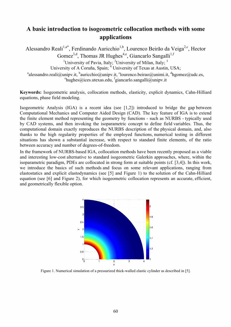
60
A basic introduction to isogeometric collocation methods with some applications
Alessandro Reali1,a*, Ferdinando Auricchio1,b, Lourenco Beirão da Veiga2,c, Hector Gomez3,d, Thomas JR Hughes4,e, Giancarlo Sangalli1,f
1University of Pavia, Italy; 2University of Milan, Italy; 3 University of A Coruña, Spain; 4 University of Texas at Austin, USA;
[email protected], [email protected], [email protected], [email protected], [email protected], [email protected]
Keywords: Isogeometric analysis, collocation methods, elasticity, explicit dynamics, Cahn-Hilliard equations, phase field modeling.
Isogeometric Analysis (IGA) is a recent idea (see [1,2]) introduced to bridge the gap between Computational Mechanics and Computer Aided Design (CAD). The key feature of IGA is to extend the finite element method representing the geometry by functions - such as NURBS - typically used by CAD systems, and then invoking the isoparametric concept to define field variables. Thus, the computational domain exactly reproduces the NURBS description of the physical domain, and, also thanks to the high regularity properties of the employed functions, numerical testing in different situations has shown a substantial increase, with respect to standard finite elements, of the ratio between accuracy and number of degrees-of-freedom.
In the framework of NURBS-based IGA, collocation methods have been recently proposed as a viable and interesting low-cost alternative to standard isogeometric Galerkin approaches, where, within the isoparametric paradigm, PDEs are collocated in strong form at suitable points (cf. [3,4]). In this work, we introduce the basics of such methods and focus on some relevant applications, ranging from elastostatics and explicit elastodynamics (see [5] and Figure 1) to the solution of the Cahn-Hilliard equation (see [6] and Figure 2), for which isogeometric collocation represents an accurate, efficient, and geometrically flexible option.
Figure 1. Numerical simulation of a pressurized thick-walled elastic cylinder as described in [5].

61
Figure 2. Numerical simulation snapshot of the spinodal decomposition of two immiscible fluids as described in [6].
References
[1] Hughes, T.J.R., Cottrell, J.A., Bazilevs, Y., Isogeometric analysis: CAD, finite elements, NURBS, exact geometry, and mesh refinement. Computer Methods in Applied Mechanics and Engineering, vol. 194, pp. 4135-4195 (2005).
[2] Cottrell, J.A., Hughes, T.J.R., Bazilevs, Y., Isogeometric Analysis. Towards integration of CAD and FEA. Wiley, (2009).
[3] Auricchio, F., Beirão da Veiga, L., Hughes, T.J.R., Reali, A., Sangalli, G., Isogeometric Collocation Methods. Mathematical Models and Methods in Applied Sciences, vol. 20, pp. 2075-2107 (2010).
[4] Schillinger, D., Evans, J.A., Reali, A., Scott, M.A., Hughes, T.J.R. Isogeometric Collocation: Cost Comparison with Galerkin Methods and Extension to Adaptive Hierarchical NURBS Discretizations. Computer Methods in Applied Mechanics and Engineering, vol. 267, pp. 170-232 (2013).
[5] Auricchio, F., Beirão da Veiga, L., Hughes, T.J.R., Reali, A., Sangalli, G., Isogeometric collocation for elastostatics and explicit dynamics. Computer Methods in Applied Mechanics and Engineering, vol. 249-252, pp. 2-14 (2012).
[6] Gomez, H., Reali, A., Sangalli, G., Accurate, efficient, and (iso)geometrically flexible collocation methods for phase-field models. Journal of Computational Physics, vol. 262, pp. 153-171 (2014).

62
On the state update for isotropic elasto-plastic hardening materials: a dissipation-based algorithm
Nicola A. Nodargi*, Edoardo Artioli, Federica Caselli and Paolo Bisegna Department of Civil Engineering and Computer Science
University of Rome "Tor Vergata", via del Politecnico 1, 00133 Rome, Italy
[email protected], URL: www.dicii.uniroma2.it
Keywords: Plasticity, Hardening, Incremental problems, Energy minimization, Dissipation, Integration algorithm
The solution of inelastic structural boundary value problems in a typical finite element implementation requires the numerical integration of the material constitutive law at each Gauss point. In the context of hardening elasto-plastic media, the kinematic description of the material state is provided through the total strain ε, additively decomposed into its elastic εe and plastic εp parts, and the strain-like internal variables α, i.e. kinematic and isotropic hardening variables. The corresponding conjugated stress-like variables are the stress σ and the stress-like internal variables q respectively.
In a strain-driven framework, the material state has to be updated for a given total strain increment. A standard approach for the integration of the constitutive law is the use of elastic-predictor inelastic-corrector return map algorithms. In a first step it is checked whether the state determined with the assumption of no plastic evolution is plastically admissible. In case not, a solution for plastic evolution equations, i.e. flow rule, hardening law and plastic consistent condition, is sought for in the plastic corrector step. To this purpose, a common strategy in practical applications is a backward-Euler-type approximation of the governing equations, leading to the so-called closest-point projection algorithm (e.g. see [1]).
Under the assumptions of (i) associative flow rule, (ii) convex Helmholtz free energy function ψ(εe, α) and (iii) convex yield function f (σ, q), the approximated equations governing the plastic evolution can be recast in a variational framework. In that approach, the minimization of a functional involving the complementary energy χ (σ, q), i.e. the Fenchel conjugate of the free energy, with respect to plastically admissible stress σ and stress-like internal variables q is required [2]. However the constrained character of the return map strategy and the numerical difficulties in convergence when the yield surface presents singularities or points with large curvature motivate the development of alternative techniques.
The present work focuses on an equivalent statement of the aforementioned variational formulation (e.g. see [3]). In a time-discrete framework, this allows to update the material state from time tn to time tn+1 by solving the infimum problem
inf Δεp,Δα ψ εn+1 εnp Δεp, Δα + D Δεp, Δα , (1)
where Δεp= εn+1p εn
p, Δα = αn+1 αn are the increments of plastic strain and strain-like internal variables respectively and
D Δεp, Δα = sup σ, q f (σ, q) ≤
σ · Δεp + q · Δα (2)
is the dissipation function, i.e. the support function of the elastic domain.

63
The present work exploits this dissipation-based variational formulation to perform the material state update. To this purpose, a two-step algorithm is proposed. In the first step, an elastic prediction of the updated material state is carried out. In case it is not plastically admissible, the infimum problem Eq. 1 is solved adopting the Newton-Raphson method. An efficient strategy to compute the dissipation function for isotropic yield criteria is proposed. In particular, adopting the Haigh-Westergaard representation (e.g. see [4]) for the analysis of isotropic yield functions, the supremum problem Eq. 2 is reduced to a non-linear scalar equation. Moreover closed-form expressions for the gradient and the Hessian of Haigh-Westergaard coordinates and dissipation function are presented. With the aim of proving the robustness and stability of the proposed algorithm, numerical tests on a single integration point and FEM simulations are provided. This numerical approach appears to be competitive with the typical return map strategy, especially when the yield surface presents singularities or points with large curvature because no difficulty in convergence arises.
References
[1] J.C. Simo, T.J.R. Hughes, Computation inelasticity, Springer Verlag, New York, 1998.
[2] F. Armero, A. Perez-Foguet, On the formulation of closest-point projection algorithms in elastoplasticity - part I: The variational structure, Int. J. Numer. Meth. Engng., 53 (2002), 297-329.
[3] W. Han, B. Reddy, Plasticity. Mathematical theory and numerical analysis, Springer Verlag, Berlin, 1999.
[4] G. Nayak, O. Zienkiewic, Convenient forms of stress invariants for plasticity, Proceedings of the ASCE Journal of the Structural Division, 98(ST4) (1972), 949-953.

64
A Lagrangian finite element approach for the numerical simulation of landslide runouts
Massimiliano Cremonesia *, Francesco Ferrib and Umberto Peregoc Department of Civil and Environmental Engineering, Politecnico di Milano, Italy
[email protected], [email protected], [email protected]
* corresponding author
Keywords: landslide simulation, Lagrangian finite element approach, slip boundary conditions.
Landslides are extreme natural phenomena frequently occurring in our country and causing casualties and extensive damage to residential structures, infrastructures and to the historical and cultural heritage.
The numerical simulation of these events requires capabilities for tracking evolving interfaces and free surfaces, accounting for the mixing of different constituents, for complex constitutive behaviors, extremely large deformations and possible multi-physics processes.
Recently, several scientific contributions have treated landslides as viscous fluids in motion (see e.g. [1]), an approach that has opened the way to new applications of computational methods conceived for the simulation of fluid problems. While in the case of fluids most approaches are developed in an Eulerian framework, in the case of landslides, the complex constitutive behavior of the soil and the rapidly evolving free surface are more appropriately modeled with a Lagrangian approach. The PFEM (Particle Finite Element Method) [2] is an innovative Lagrangian numerical method, particularly suited to the solution of problems with interactions between fluids and structures.
In the PFEM, the Navier-Stokes equations, governing the motion of fluids and structures, are approximated using a material formulation (Lagrangian) in which the mesh nodes move together with material particles. For this reason, in order to emphasize the material description of motion, the nodes are named 'particles'. All the physical properties such as density, viscosity, velocity, position, and other variables such as temperature, are assigned to the particles and are transported during the motion of the mesh nodes. The problem of elements distortion due to the large deformations of the moving fluid, is solved with a very efficient and continuous mesh re-triangulation based on the Delaunay technique [2,3,4] and driven by a fast and effective geometric distortion criterion.
A non-Newtonian constitutive law has been introduced to describe the behavior of the granular material, which is assumed to be incompressible in the landslide running out regime. The deviatoric stress is related to the deviatoric strain rate through an apparent viscosity defined as:
2 tan| |
1 | |
where is the pressure field, is the friction angle and n is a regularization parameter.
To better describe the interaction between the moving landslide and the slope substrate, slip boundary conditions have been introduced. The velocity component along the slope is written as:
0
where is the tangential stress, 0 represents a stress threshold, below which no slip can occur, and a parameter, having the dimensions of a length over a viscosity, defining the amount of slip. This
condition states that the slip is resisted by a tangential force proportional to the relative velocity. For 0 the no-slip boundary condition is recovered, while → ∞ represents the stress free boundary
condition.

65
The proposed approach has been validated against experimental tests, showing a good agreement with the expected results. In Figure 1 an example of a tridimensional simulation of a landslide along a slope is presented.
Figure 1: Propagation of a landslide on a slope: snapshots at different time istants.
References
[1] M. Quecedo, M. Pastor and M.I. Herreros, Numerical modelling of impulse wave generated by fast landslides, International journal for numerical Method in Engineering, 59(12), pp.1633-1656, (2004).
[2] E. Oñate, S.R. Idelsohn, F. del Pin and R. Aubry. The Particle Finite Element Method. An Overview. International Journal Computational Method, 1(2), pp. 267-307, (2004).
[3] M Cremonesi, A. Frangi, A. and U. Perego, A Lagrangian finite element approach for the analysis of fluid-structure interaction problems. International journal for numerical Method in Engineering 84:pp 610-630 (2010).
[4] M.Cremonesi, A. Frangi, U. Perego, A Lagrangian finite element approach for the simulation of water-waves induced by landslides, Computers &.Structures, 89(11-12), pp. 1086-103, (2011).
66
Geometry of elastoplasticity in the nonlinear range
Giovanni Romano, Raffaele Barretta and Marina Diaco
Department of Structures for Engineering and Architecture,
University of Naples Federico II, Italy
via Claudio 21 – 80125 - Naples,
[email protected] - [email protected] - [email protected]
Keywords: Material and spatial fields, rate-elastoplaticity, naturality and frame invariance, Lie-derivatives.
The conceptual and operational revisitation of fundamentals of Continuum Mechanics, carried out in a series of recent contributions by the authors [1-6], is applied to the formulation of a geometrically consistent theory of Elasto-Plasticity in the full nonlinear range.
The bias of the presentation is towards physical and geometrical new ideas and notions involved in the analysis.
Main issues are the natural definition of material and spatial tensor fields and a list of four basic geometric principles to be addressed in a constitutive theory.
Treatments in literature are revisited to underline the need for the new geometric theory according to which, in the constitutive framework, only current placements of the body are to be considered and only relations between material tensor fields, with a common base point in the space-time trajectory, are involved.
The rate elastic and plastic responses to stress and stress-rate are assumed as additive components of the total stretching. Reference local manifolds are considered as purely computational tools. Unphysical notions such as reference and intermediate local configurations are eliminated from the basic constitutive formulation and referential finite elastic and plastic strains are shown to have a purely computational role without physical interpretation.
The requirement of invariance under change of observer is treated anew to provide a correct geometric interpretation of the physical experience.
The outcome is a model of nonlinear Elasto-Plasticity testable by experiments, suitable for implementation in computational codes and apt to provide a consistent treatment of other complex constitutive behaviors such as phase transformations in metal alloys or tissue growth in biomechanics.
References
[1] G. Romano, R. Barretta, Covariant hypo-elasticity, Eur. J. Mech. A-Solids 30 (2011) 1012-1023.
[2] G. Romano, R. Barretta, On Euler's Stretching Formula in Continuum Mechanics, Acta Mech. 224 (2013) 211-230.
[3] G. Romano, R. Barretta, Geometric Constitutive Theory and Frame Invariance, Int. J. Non-Linear Mech. 51 (2013) 75-86.
[4] G. Romano, R. Barretta, M. Diaco, Geometric Continuum Mechanics, Meccanica 49 (1) (2014) 111-133.
[5] G. Romano, R. Barretta, M. Diaco, Rate Formulations in Non-Linear Continuum Mechanics
Acta Mech. online (2013) doi: 10.1007/s00707-013-1002-3
[6] G. Romano, R. Barretta, M. Diaco, The Geometry of Non-Linear Elasticity Acta Mech. online (2014) doi: 10.1007/s00707-014-1113-5

67
FE-Meshless multiscale non linear analysis of masonry structures
Giuseppe Giambanco 1,a *, Emma La Malfa Ribolla1,b and Antonino Spada1,c 1Department of Civil, Environmental, Aerospace and Materials Engineering (DICAM)
University of Palermo, Viale delle Scienze – Ed. 8, 90128 Palermo, Italy [email protected], [email protected], [email protected]
* corresponding author
Keywords: multiscale, mesomodeling, meshless, masonry.
In masonry structures, the most relevant kinematical and mechanical phenomena take place at a scale which is small if compared to the dimensions of the structure. On the other side, the structure is governed, in its peculiar overall response, by its global geometrical and morphological configuration. In literature, two different scales of interest are distinguished, directly linked to as many theoretical approaches: the mesoscopic approach and the macroscopic approach. The mesoscopic approach considers the heterogeneous materials and their interfaces individually [1, 2], but many difficulties arise in the mesh creation and a fine discretization of the structure has to be used, which leads to prohibitive computational costs. The macroscopic approach considers the structure constituted by a fictitious homogeneous and continuous material. The multiscale techniques belong to the second approach and couple different scales of interest by means of apposite transition laws capable to exchange information between different consecutive scales [3-5].
In this work a multiscale first order computational homogenization technique is applied to simulate masonry structures. A unit cell (UC) is identified. The UC is assumed constituted by a block surrounded by mortar joints, which are simulated by zero-thickness interface models. The material of the block is assumed indefinitely elastic while the interface laws are expressed in the framework of elastoplasticity.
The scale transition between macroscale and mesoscale is based on the Hill-Mandel principle. By imposing the equilibrium over the entire structure, the displacement Mu and strains Mε fields at the
macroscopic level are derived. The macroscopic stress field Mσ associated to the strain field Mε is
instead obtained averaging the UC reactions r over the volume UC . To this end, the response of the
UC is evaluated by solving a boundary value problem, that in this work are assumed to be of Taylor-Voigt type:
m M UCon u ε x (1)
where mu are the prescribed displacements for the point of position x located on the boundary UC of
the UC. Once the solution of the boundary value problem is obtained, the macroscopic stress Mσ is
calculated according to the following equation:
1
2UC
MUC
d
σ r x x r (2)
The interface constitutive laws are developed in the framework of elastoplasticity for non standard materials. The elastic domain is defined by two convex limit surfaces intersecting in a non-smooth fashion: the Coulomb bilinear limit surface and a tension cut-off. Non-associative flow rules are derived to express the displacement discontinuities at the interfaces.

68
The solution of the UC boundary value problem is generally approached in an approximated way making use of the finite element method. In the present study the numerical solution of the mesoscopic model is obtained by means of a meshless strategy [6]. The UC is divided in five integration domains: the first domain corresponds to the volume occupied by the block, the other four domains are the interfaces. The displacement field inside each sub-domain is obtained from the nodal displacement values by a Moving Least Square approximation. The influence of a node on a point on the UC is defined by a weight function depending on the distance between the sampling point and the node.
The proposed model has been implemented on a research oriented finite element analysis program to run 2D simulations on masonry structures.
The solution can be separated in an elastic and a plastic phases. To find an elasto-plastic solution the interface constitutive laws are rewritten in a discrete way and integrated for a given incremental strain history. The solution over a single time step is obtained employing a Backward Euler integration scheme, separated in an elastic predictor stage and a plastic corrector stage. The governing equations for the UC at the elasto-plastic step are finally expressed in matrix form as follows:
pm
m
T
FK -G U
UG 0 R (3)
where K and G are two matrices depending on the UC geometry, mU is the increment of nodal
displacements, R the increment of nodal reactions, pF the elasto-plastic forces evaluated in the
correction stage, mU the imposed displacements on boundary nodes.
A macroscopic elastic tangent stiffness matrix can be evaluated at each integration point and a procedure is performed to localize the plastic zones at the macroscale, starting from the results at the mesoscale.
The FE-Meshless multi-scale computational strategy has been applied to simulate experimental tests available in literature in plane-stress conditions. The classical finite element analysis is run at the macroscale, while the meshless procedure is applied at the mesoscale on the UC. Two iterative Newton-Raphson procedures have been used during the analyses: one for the macroscale finite element procedure, one for the solution of the UC in the plastic phase. The convergence criterion at the mesoscale is considered satisfied when the difference between the elasto-plastic forces between two successive iterations is less than a tolerance value.
References
[1] G. Giambanco, S. Rizzo, R. Spallino, Numerical analysis of masonry structures via interface models, Comput. Methods Appl. Mech. Eng., 190 (2001) 6493-6511.
[2] A. Spada, G. Giambanco, P. Rizzo, Damage and plasticity at the interfaces in composite materials and structures, Comput. Methods Appl. Mech. Eng., 198 (2009) 3884-3901.
[3] V. Kouznetsova, M.G. Geers, W.M. Brekelmans, Multi-scale constitutive modelling of heterogeneous materials with a gradient-enhanced computational homogenization scheme, Int. J. Numer. Meth. Eng., 54 (2002) 1235-1260.
[4] T.J. Massart, Multi-scale modelling of damage in masonry structures, PhD Thesis, University of Technology, Eindhoven, 2003.
[5] D. Addessi, E. Sacco, A multi-scale enriched model for the analysis of masonry panel, Int. J. Solids and Struct, 49 (2012) 865-880.
[6] S.N. Atluri, S. Shen, The meshless method, Tech. Sci. Press, Forsyth, 2002.
69
Non-linear analysis of 3D elastoplastic framed structures
Valerio Carollo1, a, Giuseppe Giambanco1,b*, and Antonino Spada1,c 1Department of Civil, Environmental, Aerospace, and Materials Engineering
University of Palermo - Viale delle Scienze, Edificio 8, 90128 Palermo – Italy. [email protected], [email protected], [email protected]
* corresponding author
Keywords: elastoplastic frames, finite elements, lumped hinge model.
Studies on the post-elastic behavior of materials and structures have permitted the updating of national and international codes with particular reference to the design of structures in seismic zones. More severe conditions are also imposed for those regions declared seismic and zones considered non-seismic in the past are today included into these categories. Most of buildings are therefore inadequate with respect to the prescriptions of actual codes. In the worst case some structures have not been designed to absorb horizontal actions. The evaluation of the vulnerability of existing structures to seismic loads is therefore of extreme importance and can be done by performing nonlinear finite element analyses. In literature, with respect to framed structures, three different finite element models are utilized to describe the elastoplastic behavior of a beam/column element [1]: lumped models, distributed nonlinearity models, fiber models. Lumped models consider the constitutive nonlinearity concentrated at a section level of a frame element, usually employing nonlinear springs at the ends of beam/column elements [2]. Distributed nonlinearity models average the nonlinearity over a finite element by considering the possibility to form plastic hinges at different evaluation points of the element and calculating weighted integrals of the section responses [3]. Fiber models subdivide a section with a large number of finite elements and nonlinearity is related to the stress-strain relationship of a single finite element [4].
The present work concentrates on the framework of lumped models. A new three-dimensional two-node Euler-Bernoulli beam/column finite element is proposed with the aim to run nonlinear analyses on 3D RC framed structures. With respect to the existing lumped models where plastic hinges can develop only at the two ends of an element, the proposed model is based on the possible formation of a maximum of three hinges, in any way positioned inside the finite element. This choice reduces the computational costs associated with the employment of remeshing procedures when a hinge doesn’t form at the ends of an element.
The basic concept is related to the possibility to split the kinematical behavior of a frame element in two different parts when a new hinge is formed at a certain point of the element. In other words, an entire element can be thought as the connection of two or more sub-elements in each one of them a displacement field can be defined and linked to the others by beams of an Heaviside function:
1 2w x w x H a x w x H x a (1)
where w x , 1w x , and 2w x are the displacement fields of the entire element, the first sub-
element and of second sub-elements respectively, H is the Heaviside function of the enclosed
quantity, a identifies the position of the plastic hinge.
The nonlinear behavior of the hinge is defined in the framework of a thermo-dynamically consistent elastoplastic theory. An elastic-perfect plastic constitutive behavior of the hinge is considered.
State equations and flow rules are derived from a Helmholtz free potential energy [5,6]. A polyhedric activation domain is defined on the internal normal force and bending moments reference system to control the onset and evolution of plasticity at the hinge. For a reinforced concrete cross-section with

70
generic dimensions and position and quantity of steel bars, the polyhedric domain is obtained considering a finite number of points, related to the most important states of stress acting on the section [7].
The hinge is assumed to have a plastic behavior only with respect to the section curvatures, while an elastic behavior is considered in the axial direction. A non associative procedure is followed: on the base of the internal axial force registered at a certain section of the element, the polyhedric domain is cut by a plane at a constant value of axial force to obtain a 2D activation domain depending on the bending moments only.
The elastoplastic frame element has been introduced in a finite element analysis program to run nonlinear simulations on 2D and 3D framed structures. To this end state equations and flow rules have been rewritten in a discrete manner. A classical elastic predictor phase is followed by a plastic corrector phase in the case of activation of the inelastic phenomenon. The corrector phase is based on the evaluation of correct bending moments by employing the closest point method, which permits to satisfy the following loading-unloading conditions:
0; 0; 0pi pi pi pi (2)
where pi is the generic plane which determines part of the limit surface of the elastic domain and pi
is the lagrangian multiplier associated.
The formation of one or more hinges inside a finite element modifies the distribution of stresses inside that element and its stiffness matrix. As a consequence, the global stiffness matrix is continuously modified at each plastic load step.
Two Newton-Raphson iterative loops have been implemented. The first one is within a single time step and permits to reach the convergence inside a single element when plasticity is activated and a hinge formed. The second one permits to reach the convergence of the overall structure as in a standard finite element procedure. The iterative procedure is stopped when the structure becomes labile and the first collapse mechanism is formed.
Numerical examples are finally reported to validate the efficiency of the proposed model. The effectiveness of the model is obtained by comparing the results with those available in literature.
References
[1] F.F. Taucer, E. Spacano, F.C. Filippou, A fiber beam-column element for seismic response analysis of reinforced concrete structures, Report No UCB/EERC-9117 Earthquake Engineering Research Center, Berkley, 1991.
[2] M. Giberson, The response of nonlinear multi-story structures subjected to earthquake excitations, Earthquake Engineering Research Laboratory, Pasadena, 1967.
[3] T. Takayanagi, W. Schnobrich, Non linear analysis of coupled wall systems, Earthquake Engineering and Structural Dynamics, 7 (1979) 1-22.
[4] C.A. Zeris, S.A. Mahin, Behavior of reinforced structures subjected to biaxial excitation, Journal of Structural Engineering, ASCE, 117(ST9) (1991) 2657-2673.
[5] A. Spada, G. Giambanco, P. Rizzo, Damage and plasticity at the interfaces in composite materials and structures, Comput. Methods Appl. Mech. Engrg., 198 (2009) 3884–3901.
[6] J. Lemaitre, J.L. Chaboche, Mechanics of Solid Materials, Cambridge University Press, 1990.
[7] R. Park, T. Paulay, Reinforced concrete structures, John Wiley & Sons Inc Print on, 1975.

71
Interface poroelastic laws to model fluid-induced damage in oil wells
Carlo Callari1,a * and Valentina Fasano2,b 1University of Molise, DiBT, via Duca degli Abruzzi, 86039 Termoli (CB), Italy 2 University of Rome "Tor Vergata", DICII, Via del Politecnico, 1, 00133 Roma
[email protected], [email protected]
*corresponding author
Keywords: poroelasticity, interface damage, oil/gas well integrity, underground CO2 storage.
In the life-cycle assessment of oil wells, a main issue is the debonding at the two interfaces of cement sheath with steel casing and formation rock, respectively. As far as we know, in spite of this and of other relevant effects of sheath cracking, our recent work [1] was the first application of damage mechanics in the analysis of well integrity.
The formation of an annular gap at well interfaces can be the main reason for upward leakage of fluids. In oil/gas production and in CO2 storage, such a leakage risk is an environmental issue of major concern. The same fluid pressure often acts as the driving action for the upward propagation of well interface opening, which is denoted as "micro-annulus" in petroleum engineering. It is then apparent the importance of the coupling between fluid flow and mechanical damage in the problem at hand.
Hence, as a further step, we have defined a thermodynamic potential for porous interfaces, in terms of displacement jump and fluid pressure, employing poroelastic coefficients which depend on a damage internal variable. Differentiation of this potential leads to coupled laws expressing traction, fluid content and energy release rate at the damaged interface. The evolution of damage is obtained from an energy criterion which employs the damage resistance law proposed for the non-porous case in [2].
We investigate the model ability in qualitatively reproducing the main features of the response of fluid-pressurized fractures in concrete [3]. Furthermore, we contrast the poroelastic damage model with other laws proposed for interfaces subjected to fluid pressure [4,5].
The model is incorporated in a formulation of the axisymmetric problem of a well with displacement discontinuities and fluid pressures at sheath-casing and sheath-rock interfaces. The problem solution, obtained from analytical integration in space and numerical integration in time, is employed to simulate the effects of cement shrinkage and of injected fluids on well integrity.
Acknowledgments. MIUR project on CO2 storage (PRIN 2010-2011, code 2010BFXRHS-004)
References
[1] C. Callari, V. Fasano, Damage analysis for wells in CO2 storage sites, in: G. Meschke et al. (Eds.), EURO:TUN 2013, Aedificatio Publishers, 2013, pp. 437-448.
[2] Y. Mi, M.A. Crisfield, G.A.O. Davies, H.B. Hellweg, Progressive delamination using interface elements, J. Compos. Mater. 32 (1998) 1246–1272.
[3] E. Brühwiler, V.E. Saouma, Water fracture interaction in concrete. Part II: Hydrostatic pressure in cracks, ACI Mater. J., 92 (1995), 383-390.
[4] G. Bolzon, G. Cocchetti, Direct assessment of structural resistance against pressurized fracture, Int. J. Numer. Anal. Met. 27 (2003), 353-378.
[5] G. Alfano, S. Marfia, E. Sacco, A cohesive damage-friction interface model accounting for water pressure on crack propagation, Comput. Methods Appl. Mech. Eng. 196 (2006), 192-209.

72
Formulation of rate-dependent cohesive-zone models
Giulio Alfano1, a * and Marco Musto1,b 1 School of Engineering and Design, Brunel University, Kingston Lane, Uxbridge, UB8 3PH, UK
[email protected], [email protected]
Keywords: fracture energy, rate-dependence, interface elements, viscoelasticity, viscoplasticity.
Rate dependent crack initiation and propagation has been the subject of extensive experimental, theoretical, analytical and numerical studies. This is because in many problems of great engineering interest the dependence of fracture processes on the loading rate cannot be ignored and often plays a key role.
The complexity of the problem and the presence of numerous competing factors is evident from the fact the fracture toughness may not show a monotonic trend with respect to crack speed, even when the latter is small enough not to consider inertial effects. Furthermore, even when such trend is monotonic, fracture toughness can increase with crack speed for some materials and decrease for others [1, 2]. In some cases, the rate dependence of the crack growth can lead to unstable crack growth or stick-slip crack propagation, the latter being a sequence of transitions from slow and stable crack growth to very fast and unstable crack propagation and vice versa.
Theoretically, the problem can be studied in the framework of Griffith theory of fracture, by observing that in the rate-dependent case the fracture energy , intended as the total energy dissipated per unit of new formed crack area, is a function of crack speed , i.e. . In this framework it can be shown that crack speed instabilities may occur if is decreasing in part of its domain, see for example [3, 4]. Within this theoretical framework, models are of a rather phenomenological nature, whereby is determined experimentally.
Cohesive-zone models (CZMs) represent a widely used alternative method to analyse crack growth. If they are developed within a damage-mechanics formulation a damage variable ranging between 0 and 1 can be introduced with the usual meaning. The natural extension of the above described phenomenological approach is to assume a rate-dependent evolution law for in such a way that the entire power dissipated is a non-linear function of .
An alternative approach consists of introducing other internal variables , 1,2, … , , within the CZM to capture different dissipation mechanisms, so that the entire dissipated power is a function not only of but also of [5]. The advantage of this approach is that the internal variables and their evolution laws can provide a much richer description of the actual dissipation mechanisms which occur at a micro-mechanical scale. This can lead to a model which is based more on first principles and less on phenomenological assumptions
In this contribution attention will be focussed on rate-dependent CMZs developed within the framework of thermodynamics with internal variables using this latter of the above described approaches. In particular, a rate-dependent model will be presented in which (i) a rate-independent evolution law is assumed for the damage variable and (ii) additional internal variables are associated with either viscoelastic or viscoplastic dissipation.
The introduction of a viscoelastic dissipation potential was considered in Ref. [5] where with the use of a simple linear viscoelastic model with an exponential kernel and a single relaxation time good agreement was obtained between numerical and experimental results for a DCB specimen with metallic arms bonded through a rubber interface tested at different loading rates in displacement-control. Figure 1 shows that the correlation between experiments and prediction is rather good for displacement rates between 0.1 mm/min to 100 mm/min, which is the expected captured range for continuum problems if a viscoelastic model with one relaxation time only is used.

73
Figure 1: comparison between experimental and numerical load-displacement curves for the DCB specimen made of steel
arms with a rubber interface tested at different loading rates [5].
It is possible to show that the use of a viscoplastic dissipation potential can make the overall specific dissipation a decreasing function of the applied rate of displacement jump on the interface. In a structural problem, this implies that the total dissipation is a decreasing function of the crack speed, and this leads to the prediction of crack velocity jumps and stick-slip crack propagation.
In this contribution, the above outlined general approach to the derivation of rate dependent crack propagation will be described. Furthermore, recent developments will be presented, including the formulation of more sophisticated viscoelastic models capturing a wider range of crack propagation speeds. Finally, the ability of viscoplastic models to capture stick-slip crack propagation will be demonstrated by presenting selected numerical results in good agreement with experimental data.
References
[1] R. Frassine, M. Rink, and A. Pavan. Viscoelastic effects on the interlaminar fracture toughness of epoxy/carbon fibre. International J. Comp. Mat., 27:921–933, 1993.
[2] R. Frassine, M. Rink, and A. Pavan. Viscoelastic effects on the interlaminar fracture behaviour of thermoplastic matrix composites: II. Rate and temperature dependence in unidirectional peek / carbon-fibre laminates. J. Comp. Sci. Techn., 56:1253–1260, 1996.
[3] D. Maugis. Subcritical crack growth, surface energy, fracture toughness, stick-slip and embrittlmenent. J. Mater. Sci., Vol. 20, pp. 3041-3073, 1985.
[4] T.W. Webb and E.C. Aifantis, Oscillatory fracture in polymeric materials. Int. J. Sol. Struct., Vol. 32, pp. 2725-2743, 1995.
[5] M. Musto and G. Alfano, A novel rate-dependent cohesive-zone model combining damage and visco-elasticity. Comput. Struct., Vol. 118, pp. 126-133, 2013.

74
Porous shape memory alloys: a micromechanical analysis
V. Sepe1, a * , F. Auricchio2,b, S. Marfia1, c, E. Sacco1,d 1DiCeM, Department of Civil and Mechanical Engineering,
University of Cassino and Southern Lazio, Italy 2 DICAr, Department of Civil Engineering and Architecture, University of Pavia, Italy
a [email protected], b [email protected], c [email protected], d [email protected]
Keywords: Shape Memory Alloys, Porous Shape Memory Alloys, Nonuniform Transformation Field Analysis.
Shape Memory Alloys (SMA) are characterized by a very special behavior due to their capability to undergo reversible changes of the crystallographic structure, depending on the temperature and on the stress state. These changes can be interpreted as reversible martensitic transformations between a crystallographic more-ordered parent phase, the austenite, and a crystallographic less-ordered product phase, the martensite.
Thanks to their unique properties over the last decades SMA have been used for a large number of applications in several engineering fields, from aerospace to medical device industries.
Recently, driven by biomedical applications, a great interest has arisen concerning a particular class of SMA: the porous SMA. The possibility of producing SMA in porous form has opened new fields of applications owing to their low-weight with high energy dissipation properties.
In the biomedical field, thanks to their high biocompatibility and their capacity to exhibit high strength, NiTi foams have been tested as bone implant materials, effectively exhibiting a considerable amount of bone ingrowth.
In the last years, applications of porous SMA in the field of Civil and Mechanical Engineering have also been considered. The potential applications of porous SMA exploit their ability to carry significant loads and their high energy absorption capability. In fact, the porous SMA show a higher specific damping capacity under dynamic loading conditions with respect to the dense SMA, because the pores facilitate an additional absorption of the impact energy.
In order to correctly reproduce the behavior of the porous SMA the development of accurate models describing their properties is needed.
The porous SMA material can be treated as a composite with SMA as the matrix and pores as the inclusions. Several works available in literature, for instance [1],[2], developed micromechanical averaging techniques in order to derive the mechanical response of porous SMA.
Indeed, different micromechanical and homogenization techniques can be applied to model porous SMA, such as the Eshelby dilute inclusion technique, the Mori-Tanaka method or the self-consistent one. An interesting approach that has been adopted to study the behavior of porous materials is based on the assumption of having a periodic distribution of pores. In this case, the problem can be solved by using a computational homogenization technique based, for instance, on nonlinear finite element analyses of a single unit cell with suitable boundary conditions.
The behavior of porous SMA under cyclic loading conditions has been studied in [3], where the constitutive law has been enhanced to account for the development of permanent inelasticity due to stress concentrations in the porous microstructure.
The aim of the present contribution is to propose a micromechanical study of porous SMA. In particular, the response of porous SMA is derived by performing:
the nonlinear finite element micromechanical analysis for the typical repetitive unit cell, considering suitable periodicity conditions;

75
the nonuniform TFA homogenization technique based on piecewise interpolation functions of the inelastic strain field proposed by Sepe et al. [4].
According to the latter homogenization procedure, a unit cell with SMA as the matrix and pores as the inclusions is considered and divided into subsets. In each subset a nonuniform distribution of the inelastic strain, which accounts for all the nonlinear effects that arise in the SMA matrix, is adopted. In particular, the inelastic strain in each subset is given as a linear combination of selected analytical functions depending on the spatial variable. The coefficients of the linear combination are determined solving the evolutive problem.
The constitutive model proposed in [5][6] and able to reproduce the key features of the Shape Memory Alloys is adopted in both types of analysis in order to simulate the behavior of the porous SMA.
The constitutive behavior and the dissipation energy of the porous SMA will be investigated for different values of porosity and for different shapes of the pores.
Numerical applications will be developed in order to test the ability of the presented procedures to well capture the overall behavior of the special composite, correctly reproducing the key features of the Shape Memory Alloys: the pseudoelastic and the shape memory effects.
References
[1] M.A. Qidwai, P.B Entchev, D.C. Lagoudas, V.G. De Giorgi, Modeling of the thermomechanical behavior of porous shape memory alloys. Int. J. of Solids Struct. 38 (48-49) (2001) 8653–8671.
[2] P.B. Entchev, D.C. Lagoudas, Modeling porous shape memory alloys using micromechanical averaging techniques, Mechanics of Materials. 34 (1) (2002) 1–24.
[3] M. Panico, L.C. Brinson, Computational modeling of porous shape memory alloys, Int. J. Solids Struct. 45 (2008) 5613–5626.
[4] V. Sepe., S. Marfia, E. Sacco, A nonuniform TFA homogenization technique based on piecewise interpolation functions of the inelastic field, Int. J. Solids Struct. 50 (2013) 725–742.
[5] F. Auricchio, L. Petrini, A three-dimensional model describing stress-temperature induced solid phase transformations: solution algorithm and boundary value problems, Int. J. for Numer. Meth. Eng. 61 (2004) 807–836.
[6] V. Evangelista, S. Marfia and E. Sacco, Phenomenological 3D and 1D consistent models for shape memory alloy materials, Comput. Mech. 44 (2009) 405-421.

76
A corotational tetrahedral element with rotational degrees of freedom for large-displacement analysis of inelastic structures
Paolo Bisegna*, Federica Caselli, Edoardo Artioli, and Nicola A. Nodargi Department of Civil Engineering and Computer Science, University of Rome “Tor Vergata”,
Via del Politecnico 1, 00133 Rome, Italy
Keywords: Tetrahedral finite element, corotational formulation, large displacements and rotations, hybrid/mixed formulation, plasticity, shape-memory alloys.
Compared to hexahedral elements, tetrahedral elements are especially attractive in practical engineering applications involving complex geometries, since they allow for a very straightforward mesh generation, whereas automatic mesh generation is often not feasible for the former [1]. The aim of the present paper is the development of a new tetrahedral finite element accounting for material and geometric nonlinearities, in the framework of the corotational formulation.
The corotational approach is based on the idea of separating rigid body motions from purely deformational ones [2]. It is especially attractive for problems involving large displacements and small strains. In fact in those cases existing high-performance linear elements can be reused as core elements in the geometrically nonlinear context, after large rigid body motions have been filtered out. In this work a polar decomposition based corotational formulation is exploited [3,4] and original closed-form formulas are derived for the efficient computation of the nodal residual vector and of the consistent tangent stiffness tensor.
A four-node solid tetrahedron with three translational and three rotational degrees of freedom (DOFs) per node is adopted as core element. The rationale is that the accuracy of those elements is intermediate between that of the linear and quadratic elements with translations only, yet they contribute to a much smaller bandwidth and thus solution time compared to the quadratic elements [5]. Existing four-node tetrahedrons with six DOFs per node include TET4RX [6], HT4R [5], RGNTet4 [1]. The latter exhibits a somewhat stiff behaviour, whereas the first is not frame invariant. Hence, HT4R is a natural candidate as core element. The derivation of HT4R is based on a modified Hellinger-Reissner functional, that treats the rotation and the skew symmetric stress as independent fields to formulate a stabilization scheme. Unfortunately, approaches based on Hellinger-Reissner functional may not be efficient in a nonlinear material framework, usually involving the direct strain-stress relationship. An enhancement of HT4R is here proposed, based on a modified Hu-Washizu functional:
Ϝ(u, ε, σ, ω, τ) = < ψ(ε) - σ·ε + σ·Du + τ·(Lu - ω) - ||τ||2/(2μγ) >. (1)
where <·> is the integral operator over the element domain, ε is the strain tensor, ψ is the free energy density, σ and τ are the symmetric and skew-symmetric parts of the stress tensor, respectively, u is the displacement vector, ω is the independently assumed rotation vector, μ is a typical stiffness modulus, γ is an arbitrary positive non-dimensional parameter. Moreover, D and L are the differential operators for deriving, respectively, the strain and rotation from the displacement field. As in the original formulation, the corner rotations are introduced by transformation of the mid-side translational DOFs of a ten-node tetrahedron, and the same stress modes are adopted, which were reduced to minimum without sacrificing the frame invariance and proper rank of the element [5]. Here two different choices are made for the assumed strain field: either the same interpolation as the stress field is assumed, amounting to fitting the displacement-derived strain field into the assumed strain field by means of a least squares procedure, or a piece-wise constant discontinuous strain field is adopted, related to the quadrature rule.

77
Besides elastic case studies, simulations involving plastic or shape-memory-alloy materials are presented. In particular, stent structures used in biomedical engineering are usually designed to significantly reduce their diameter during the insertion into a catheter. Thereby large rotations and displacements, usually combined with small to moderate strains, occur. Dissipation pseudo-potential, along with chemical and transformation-strain energies in the case of shape-memory alloys, are accordingly accounted for in formulation (1), and a dissipation-based material state-update algorithm is adopted.
References
[1] R. Tian, H. Matsubara, G. Yagawa, Advanced 4-node tetrahedrons, Int. J. Numer. Methods Eng. 68(2006):1209-1231.
[2] B. Nour-Omid, C. C. Rankin, Finite rotation analysis and consistent linearization using projectors, Comput. Meth. Appl. Mech. Eng. 93(1991):353-384.
[3] G. F. Moita, M. A. Crisfield, A finite element formulation for 3-D continua using the co-rotational technique, Int. J. Numer. Methods Eng. 39(1996):3775-3792.
[4] F. Caselli, P. Bisegna, Polar decomposition based corotational framework for triangular shell elements with distributed loads, Int. J. Numer. Methods Eng. 95(2013):499-528.
[5] K. Y. Sze, Y. S. Pan, Hybrid stress tetrahedral elements with Allman’s rotational D.O.F.s, Int. J. Numer. Methods Eng. 48(2000):1055-1070.
[6] T. P. Pawlak, S. M. Yunus, R. D. Cook, Solid elements with rotational degrees of freedom: Part II - tetrahedron elements, Int. J. Numer. Methods Eng. 31(1991):593-610.

78
A consistency study of cohesive zone models for mixed-mode debonding problems
Rossana Dimitri1,a *, Marco Trullo1,b, Laura De Lorenzis2,c and Giorgio Zavarise1,d 1Dipartimento di Ingegneria dell'Innovazione, Università del Salento,
Via per Monteroni, 73100, Lecce 2 Institut für Angewandte Mechanik, Technische Universität Braunschweig,
Bienroder Weg 87, Campus Nord, 38106 Braunschweig, Germany [email protected], [email protected], [email protected],
Keywords: Cohesive zone modeling, Debonding, Mixed-mode fracture.
Cohesive zone models (CZMs) are commonly used to describe mixed-mode failure and debonding processes at material interfaces or within quasi-brittle materials. These models consist in non-linear relationships between tractions and relative displacements across the crack. Although a large number of CZMs have been proposed, and despite the extensive related literature, little attention has been devoted to ensuring the consistency of these models for mixed-mode conditions, primarily in a thermodynamical sense. For many of these models, traction-separation laws have been directly postulated in an ad hoc manner, which may lead to unphysical dissipation behavior.
A consistency check was performed by van den Bosch et al. [1] for the exponential model by Xu and Needleman [2]. Thereby, an adjusted non-potential-based exponential model was also proposed to correct the unphysical behavioral features of the original model in the description of mixed-mode decohesion. Although non-potential-based models have been adopted for many practical applications, this class of models is not guaranteed to be thermodynamically consistent [3]. Beside thermodynamical consistency, an important requirement of CZMs is to allow for different values of the fracture energy in the normal and tangential directions, as measured experimentally.
In the first part of this contribution, two widely used mixed-mode CZMs [4,5] are examined. The consistency of their predictions in both stress and energy terms is checked. A parametric analysis on the effect of the coupling parameters on stress distributions and energy dissipation is performed in order to evaluate physical inconsistencies such as local abnormalities in the coupled elastic or softening mechanical response of the interface and incomplete dissipation of the fracture energy during decohesion. The path-dependence of the mixed-mode debonding work of separation (W) and of the failure domains are additionally evaluated. W is given by
W= pN
(gN
,gT)dg
N + pT(g
N,g
T)dg
T (1)
where Γ is the separation path, pN and pT are the normal and tangential tractions, gN and gT are the normal and tangential relative displacements across the crack. The first term in Eq. 1 is the work done by the normal tractions (WN), while the second term is the work done by the tangential tractions (WT).
Analytical predictions are also compared with results from numerical finite element models, where the interface is described with zero-thickness contact elements. A node-to-segment strategy as employed in [6] is here adopted, which incorporates decohesion and contact within a unified framework. Three case studies are analyzed for the numerical prediction of mixed-mode interface debonding: a simple patch test, a bimaterial peel test under mixed-mode loading conditions, and the standard mixed-mode bending test (MMB). Figure 1 illustrates sample analytical and numerical results in terms of W, WT and WN, obtained for a patch test with the models in [4,5]. It is evident that the total work of separation does not vary monotonically, which reveals an energetic inconsistency.

79
In the second part of the paper, a new thermodynamically consistent mixed-mode CZM is proposed based on a modification of the model in [1]. Based on a predefined Helmoltz energy, the interface model is derived by applying the Coleman and Noll procedure, in accordance with the second law of thermodynamics, whereby the inelastic nature of the decohesion process is accounted for by means of damage variables. The model accounts monolithically for loading and unloading conditions, as well as for decohesion and contact. Its performance is demonstrated through suitable examples.
0
20
40
60
80
100
120
0 0.2 0.4 0.6 0.8 1
WN, W
T, W
[Jm
-2]
gN/gN,u
WN WT W WN_num WT_num W_num
0
20
40
60
80
100
120
0 0.2 0.4 0.6 0.8 1
WN, W
T, W
[Jm
-2]
gN/gN,u
WN WT W WN_num WT_num W_num
0
20
40
60
80
100
120
0 0.2 0.4 0.6 0.8 1
WN, W
T, W
[Jm
-2]
gN/gN,u
WN WT W WN_num WT_num W_num
(a) (b) (c)
Figure 1: Work of separation for bilinear models by Högberg (a), and by Camanho et al. for a P-L criterion (b), or a B-K criterion (c). N=T=100 N/m.
Acknowledgements: The authors have received funding for this research from the European Research Council under the European Union’s Seventh Framework Programme (FP7/2007-2013), ERC Starting Researcher Grant “INTERFACES”, Grant agreement n° 279439.
References
[1] M.J. van den Bosch, P.J.G. Schreurs, M.G.D. Geers. An improved description of the exponential Xu and Needleman cohesive zone law for mixed-mode decohesion, Eng. Fract. Mech. 73 (2006) 1220-1234.
[2] X.P. Xu, A. Needleman. Void nucleation by inclusion debonding in a crystal matrix, Model. Simul. Mater. Sc. 1 (1993) 111-132.
[3] J. Mosler, I. Scheider. A thermodynamically and variationally consistent class of damage-type cohesive models. J. Mech. Phys. Solids. 59 (2011) 1647-1668.
[4] J.L. Högberg. Mixed mode cohesive law, Int. J. Fract. 141 (2006) 549-559.
[5] P.P. Camanho, C.G. Dàvila, M.F. De Moura. Numerical simulation of mixed-mode progressive delamination in composite materials, J. Compos. Mater. 37(16) (2003) 1415-1438.
[6] P. Wriggers, G. Zavarise, T.I. Zohdi. A computational study of interfacial debonding damage in fibrous composite materials, Comput. Mater. Sci. 12 (1998) 39-56.

80
A multilevel finite element approach for piezoelectric textiles made of polymeric nanofibers
Claudio Maruccio1, a *, Laura De Lorenzis2, b 1Department of Innovation Engineering, University of Salento, via Monteroni, Lecce, Italy
2Institut für Angewandte Mechanik, Technische Universität Braunschweig, Germany [email protected], [email protected]
Keywords: Electromechanical Coupling, FE2, Multiphysics Modeling, Multiscale Modeling, Piezoelectricity, Shell elements.
Piezoelectric effects are exploited in an increasing number of micro- and nano-electro-mechanical systems. In particular, energy harvesting devices convert ambient energy (i.e. mechanical pressure) into electrical energy and their study is a very important and challenging field of research. The development of novel piezoelectric nano-generators [1] promises to exert a substantial impact in several industrial fields, such as the automotive, aerospace, and medical fields.
In this paper, the attention is focused on piezoelectric textiles made of arrays of polymeric nano-fibers [2]. Due to the importance of computational modeling to understand the influence that micro-scale geometry and constitutive variables have on the macroscopic behavior, a computational homogenization procedure is developed and implemented. The method is based on a multilevel finite element approach (FE2) [3,4], whereby the macroscopic structure is discretised using the finite element method and a discretised microscale reference volume element (RVE) is assigned to each quadrature point at the macro-scale. The geometry of the RVE is based on the microstructural properties of the material under consideration and consists in piezoelectric polymer fibers subjected to electromechanical contact constraints. The contact element contributions to the virtual work equations are included using the penalty method and introducing suitable electric, mechanical and coupling potentials. A contact smoothing approach based on Bézier patches for the master surface [5] is extended to the multiphysics framework providing an improved continuity of the parameterization. For each macroscopic integration point, the macro-scale shell kinematics is used to formulate suitable boundary conditions for the corresponding RVE. Once the boundary value problem for the RVE is fully defined, from the finite element analysis at the microlevel, Figure 1, the resulting generalized stress and strain vectors in the RVE are computed.
a)
b)
Figure 1 a) RVE mesh b) Minimum and maximum stress x corresponding to the vertical color scales are -1.6 * 10−2 to 4.3 * 10−2 [nN/nm2]

81
By averaging the RVE results over the unit cell volume and after thickness integration, the generalized force vector of the shell is extracted and returned to the macroscopic integration point as a local macroscopic stress resultant. At this point the local macroscopic consistent tangent is determined performing a sensitivity analysis at the RVE level. When the analysis of all RVEs is completed, the generalized force vector is available at each macroscopic integration point and the internal macroscopic forces are calculated. If these forces are in balance with the external load according to the convergence criterion, the next time step can start, otherwise the iterative procedure is continued. Within this approach the average response resulting from the homogenization procedure at the micro-level is directly used as a multiphysics constitutive model for each quadrature point at the macro-scale.
This contribution outlines the theory and its numerical implementation, and presents the main numerical results.
References
[1] Y. Gao, Z.L. Wang, Electrostatic potential in a bent piezoelectric nanowire. The fundamental theory of nanogenerator and nanopiezotronics, Nano Lett. 7 (2007) 2499-2505.
[2] L. Persano, C. Dagdeviren, Y. Su, Y. Zhang, S. Girardo, D. Pisignano, Y. Huang, J.A. Rogers, High performance piezoelectric devices based on aligned arrays of nanofibers of PVDF, Nature Communications. 1633 (2013) 4.
[3] J. Schroeder, M. Keip, Two-scale homogenization of electromechanically coupled boundary value problems - Consistent linearization and applications, Computational Mechanics. 50 (2012) 229-244.
[4] E.W. Coenen, V.G. Kouznetsova, M.G.D. Geers, Computational homogenization for heterogeneous thin sheet, International Journal for Numerical Methods in Engineering. 83 (2010) 1180-1205.
[5] J. Lengiewicz, J. Korelc, S. Stupkiewicz, Automation of finite element formulations for large deformation contact problems, International Journal for Numerical Methods in Engineering. 85 (2011) 1252-1279.

82
Computational issues on multiscale FE analysis
Francesco Parrinelloa and Guido Borinob 1Università di Palermo, Dipartimento di Ingegneria Civile, Ambientale, Aerospaziale, dei Materiali,
Viale delle Scienze Ed.8, 90128 Palermo, Italy [email protected], [email protected]
Keywords: Multiscale, Static condensation, Master slave, Periodic boundary conditions.
Multiscale analysis typically defines the complex constitutive behavior of heterogeneous material, by an homogenization technique of the mechanical response of a material representative volume element, which is discretized in a microscale finite element model and subjected to imposed macro strain.
The homogenized stress and tangent moduli, obtained at the microscale, can be employed in a point of a macroscopic discretized structure, in a multilevel finite element framework, as proposed in [1].
The focus point of the multiscale analysis is the correct formulation of the scale transition laws, which define, as a function of the assumed macroscopic deformation, the imposed miscroscale deformation in terms of boundary displacements or boundary tractions. Moreover, the averaging theorems allow to define the homogenized stress and, by an incremental variation approach, also the
homogenized tangent moduli.
In the context of deformation-driven multiscale analysis, three types of boundary conditions are known in literature to verify the averaging theorems proposed by Hill [2]: linear displacement, constant traction and periodic displacement and antiperiodic traction. The latter approach is generally recognized to produce better results, with respect to the other two approach, for periodic microstructures.
The three boundary conditions are applied by the Lagrangian multiplier method, in the small strain hypothesis, by Miehe and Koch in [3], where algorithms and matrix representation of averaged stress and tangent moduli are derived. The same problem is analyzed in finite deformation regime in [4].
The three boundary conditions are applied by penalty approach in [5], in finite deformation context, and the averaged tangent moduli are derived by a perturbation procedure, instead of the condensation one.
The present paper investigates the multiscale analysis techniques from the computational point of view and proposes an original formulation, based on the master slave elimination method, for the application of the periodic displacement and antiperiodic traction boundary condition.
The periodic displacement boundary condition has to be applied between pairs of nodes on the boundary of microscale model and it is a non-homogenous multifreedom constrain. The boundary condition is applied by master slave elimination method, which produces an exact solution and reduces the number of unknowns. On the contrary, the penalty method produces an approximated solution and the Lagrangian multiplier method increases the number of unknowns.
The paper develops the computational aspects related to the scale transition laws. The macro stress tensor is obtained as average of the micro stress and the matrix of tangent moduli is defined as symmetric, positive defined and it is evaluated exactly by the static condensation approach [6]. The model stiffness matrix is expanded to the slave degrees of freedom, which are released, and the matrix is statically condensed to the square matrix related to the slave degrees of freedom. The static condensation is performed simply by stopping the triangular decomposition to the first released slave degree of freedom.
Some numerical multiscale analysis are performed and the results are proposed.

83
References
[1] R.J.M. Smit, W.A.M. Brekelmans, H.E.H. Meijer, Prediction of the mechanical behavior of nonlinear heterogeneous systems by multi-level finite element modeling, Comput. Methods Appl. Mech. Engrg. 155 (1998) 181–192.
[2] R. Hill, On constitutive macro–variables for heterogeneous solids at finite strain, Proc R Soc London A 326 (1972) 131–147
[3] C. Miehe, A. Koch, Computational micro-to-macro transitions of discretized microstructures undergoing small strains, Arch. Appl. Mech. 72 (2002) 300–317.
[4] C. Miehe, Computational micro-to-macro transitions for discretized microstructures of heterogeneous materials at finite strains based on the minimization of averaged incremental energy, Comput. Methods Appl. Mech. Engrg. 192 (2003) 559–591.
[5] I. Temizer, P. Wriggers, On the computation of the macroscopic tangent for multiscale volumetric homogenization problems, Comput. Methods Appl. Mech. Engrg. 198 (2008) 495–510.
[6] E. L. Wilson, The static condensation algorithm, Short Comunication on Int. Jou. Num. Meth. Eng. 8 (1974) 198–203.

84
An efficient Bouc & Wen approach for seismic analysis of masonry tower
Luca Facchini1,a , Michele Betti1,b * 1Department of Civil and Environmental Engineering, University of Florence, Italy
a [email protected], b [email protected]
Keywords: Bouc & Wen model, Masonry towers, Nonlinear dynamics, Statistical linearization.
The assessment of existing masonry towers under exceptional loads, such as earthquake loads, requires reliable, expedite and efficient methods of analysis. These approaches should take into account both the randomness that affect the masonry properties (in some cases the distribution of elastic parameters too) and the specific non-linear behavior (f.i. the small tensile strength).
As an alternative to classical finite element technique approaches, in recent years several expeditious methods have been proposed to analyze the structural response of such structural systems. An approach based on the modal reduction (MO-RE) to analyze the response of slender masonry walls under turbulent wind was proposed in [1]: the material was assumed as no tensile resistant (NTR), but the mechanical properties were assumed as deterministic. To introduce randomness in material distribution an approach based on a Galerkin discretization was proposed in [2]: the material properties were assumed as a stochastic field. Other possible expeditious approaches may be based on perturbation methods, however the results of some preliminary analysis, seem to show that the use of a perturbation method does not allow, when the seismic action is assumed as a time history, to keep into account correctly the cracking and crushing phenomena that occur in masonry.
Based on this background, and considering the need of simplified but effective methods to assess the seismic response of slender masonry tower, the paper aims to propose an efficient approach for seismic assessment of masonry towers assuming the material properties as a stochastic field. As a prototype of masonry towers a cantilever beam is analyzed assuming that the first modal shape governs the structural motion. With this hypothesis a non-linear hysteretic Bouc & Wen model [3] is employed to reproduce the system response which is eventually linearized to evaluate its bounds. The results of the simplified approach are compared with the results of FE model to show the effectiveness of the method.
References
[1] M. Betti, P. Biagini, L. Facchini, Comparison among different techniques for reliability assessment of no-tensile structures under turbulent wind, Proceedings of the Fourth European-African Conference on Wind Engineering, EACWE4 2005 (2005).
[2] L. Facchini, M. Betti, P. Biagini and A. Vignoli, RBF – Galerkin approach for the dynamics of simple disordered masonry structures, Atti del XVII Congresso Nazionale AIMETA di Meccanica Teorica ed Applicata, AIMETA 2005 (2005).
[3] Y. K. Wen, Method for random vibration of hysteretic systems, ASCE Journal of the Engineering Mechanics Division, 103(2), 249-263 (1976).

85
Analysis of masonry arches: a NURBS based simple applicative program
Andrea Chiozzi1, a *, Marcello Malagù2,b, Antonio Tralli1,c , Antonio Cazzani3,d
1University of Ferrara – Department of Engineering, Via Saragat 1 – 44100 Ferrara Italy 2Delft University of Technology, Faculty of Civil Engineering and Geosciences, Stevinweg 1,
2628CN, Delft, The Netherlands 1University of Cagliari – Faculty of Architecture, Via Marengo 2 – 09123 Cagliari Italy
a [email protected], b [email protected], c [email protected], d [email protected]
* corresponding author
Keywords: NURBS, isogeometric analysis, limit analysis, masonry arches.
In this work a practical tool for the analysis of masonry arches, which is based on a combination of isogeometric analysis and of a suitable implementation of the classic safe theorem proposed by Heyman [1] is presented. The computer code, developed in the popular Matlab language, has been designed in such a way that, by using it, professionals dealing with restoration or structural rehabilitation of historical constructions can easily produce estimates of the carrying capacity of curved members, especially, but not exclusively, arches, with a sound theoretical background. Moreover, the developed code is also devised to handle the presence of FRP (fiber-reinforced polymers) strips, thus allowing design of properly dimensioned reinforcement and its verification according to recently developed building codes.
The proposed software interacts with CAD (Computer Aided Design) design softwares, which are widely used by the community of professionals, in order to import NURBS representation of arch geometries, which become the basis for subsequent structural analysis. As is common knowledge, description and computation of geometries in commercial CAD packages are based on B-splines and NURBS (Non Rational Uniform B-Splines) basis functions. In particular, when compared to standard B-splines, NURBS basis function have the great advantage in representing the exact geometry of a wide set of curves and surfaces such as circles, ellipses and parabolas [2].
Starting from a NURBS representation of an arch with arbitrary shape, it is possible to perform at first a linear elastic analysis through isogeometric analysis. Isogeometric analysis is a recently developed computational approach that offers the possibility of integrating finite element analysis (FEA) and CAD geometry representation: the basic idea is to use the same NURBS representations both for the geometry and FEM solution space [3, 4].
Besides elastic analysis, the proposed software allows to perform a limit analysis of the masonry arch. As shown by Livesley [5], the equilibrium formulation can be applied to masonry arches leading to lower bound solutions. This approach involve the discretization of an arch into a number of rigid blocks and the solution of a linear programming problem under the classic Heyman hypothesis. In the proposed software, the NURBS geometric representation of the arch is used to easily obtain a discretization of the arch into rigid blocks. An interior-point algorithm is used to solve the optimization problem. Livesley original approach has been extended in order to include finite strength in compression for masonry, through an iterative numerical procedure, and FRP reinforcement through FRP strips at the intradox and/or at the extradox of the arch so that FRP delamination is taken into account as additional constraints to the linear programming problem.
Finally, some real-world applications, which the proposed software tool can deal with, are presented and discussed.

86
References
[1] L. Piegl and W. Tiller, The NURBS book, second ed., Springer-Verlag, Berlin, 1997.
[2] J. Heyman, “The stone skeleton”, Int. J. Solids and Structures, 2 (1966) 249-79
[3] T.J.R. Hughes, J.A. Cottrell and Y. Bazilevs, “Isogeometric analysis: CAD, finite elements, NURBS exact geometry and mesh refinement”, Computer Methods in Applied Mechanical and Engineering, 194 (2005) 4135-95.
[4] C. de Falco, A. Reali and R. Vazquez, “GeoPDEs: a research tool for Isogeometric Analysis of PDEs”, Adv. Eng. Sotw., 42(2011) 1020-1034
[5] R.K. Livesley, “Limit analysis of structures formed from rigid blocks”, Int. J. for Num. Meth. Eng.12 (1978), 1853-1871.

87
Isogeometric collocation for large-deformation frictional contact
Laura De Lorenzis, Roland Kruse, Nhon Nguyen-Thanh Institut für Angewandte Mechanik, Technische Universität Braunschweig, Germany
[email protected], [email protected], [email protected]
Keywords: isogeometric analysis, isogeometric collocation, large-deformation contact, friction
Within the framework of NURBS-based isogeometric analysis, collocation methods have been recently proposed and their accuracy and efficiency demonstrated for elastostatics and explicit dynamics [1-3]. Recently, further progress has been achieved in the application of isogeometric collocation to frictionless contact problems [4]. As the contact constraints were enforced as special Neumann boundary conditions (BCs), enhancements were needed in the general imposition of these BCs. Thereby, an enhanced collocation scheme was proposed, whereby the Neumann BCs are imposed considering both boundary and bulk contributions. This was shown to significantly improve the accuracy over the basic collocation method and to achieve an accuracy comparable to that of the Galerkin method, especially for discretizations of order larger than 3, while completely eliminating quadrature.
For contact problems between deformable bodies, the two-half-pass formulation proposed in [5] and recently extended to friction [6] seems the most natural algorithm in the collocation framework. A striking result obtained from this formulation in [4] was that, despite the pointwise evaluation of the contact residual contributions at the surface collocation points, the formulation passes the contact patch test to machine precision. Such a result has never been obtained in the Galerkin setting. The proposed frictionless contact formulation in the collocation setting yields results of very good quality for regular solutions and uniform meshes. In situations with highly non-uniform meshes, as for the more general Neumann cases, the basic collocation method fails whereas the enhanced collocation scheme proposed in [4] is an effective remedy which restores accuracy of the results and robustness of the iterative procedure.
The investigation in [4] was limited to the frictionless setting. Moreover, although the contact formulation was fully non-linear, the continuum was treated within the framework of linear elasticity, so that only small deformation cases could be tackled. Herein, two main advancements are reported:
1) The continuum formulation is extended to the large-deformation elasticity case. A few different constitutive laws are considered, namely St. Venant-Kirchhoff, compressible neo-Hooke, and a different neo-Hooke model version with volumetric-deviatoric decoupling. Special attention is given to the consistent linearization of the non-linear problem, which presents peculiar features in the collocation framework;
2) The contact formulation is extended to the frictional setting. A small-deformation case is first solved illustrating the comparison to an analytical solution. Subsequently a large-deformation problem is presented.
Isogeometric collocation is shown to represent a promising framework for the solution of non-linear frictional contact problems.
References
[1] Auricchio, F., Beirão da Veiga, L., Hughes, T.J.R., Reali, A., and Sangalli, G. (2010). Isogeometric Collocation Methods. Math. Mod. Meth. Appl. Sci., 20(11): 2075–2107.
[2] Auricchio, F., Beirão da Veiga, L., Hughes, T.J.R., Reali, A., and Sangalli, G. (2012). Isogeometric collocation for elastostatics and explicit dynamics. Comp. Meth. Appl. Mech. Engrg., 249–252: 2–14.

88
[3] Schillinger, D., Evans, J.A., Reali, A., Scott, M.A., and Hughes, T.J.R. (2013). Isogeometric Collocation: Cost Comparison with Galerkin Methods and Extension to Adaptive Hierarchical NURBS Discretizations, Comp. Meth. Appl. Mech. Engrg., accepted for publication, ICES Report 13-03, University of Texas at Austin, February 6, 2013.
[4] De Lorenzis, L., Evans, J.A., Hughes, T.J.R., Reali, A. (submitted). Isogeometric collocation: Neumann boundary conditions and contact. Submitted version available online as ICES Report 14-06.
[5] Sauer, R.A., De Lorenzis, L. (2013). A computational contact formulation based on surface potentials. Comp. Meth. Appl. Mech. Engrg., 253:369-395.
[6] Sauer R., De Lorenzis L. (revision submitted). An unbiased computational contact formulation for 3D friction. Int. J. Num. Meth. Eng.

89
An adaptive multiscale approach for the failure analysis of fiber-reinforced composite materials
Domenico Bruno1,a, Fabrizio Greco1,b*, Lorenzo Leonetti1,c, Stefania Lo Feudo,d
, Paolo Lonetti1,e
1Department of Civil Engineering, University of Calabria, Via P. Bucci, Cubo 39B, Rende (CS), Italy
[email protected], [email protected], [email protected], [email protected], [email protected]
Keywords: multiscale methods, composite materials, transverse cracking, micromechanics, failure analysis.
Composite materials may be affected by different kinds of damage phenomena, which usually start from manufacturing-induced and other pre-existing defects. Fiber-reinforced composites, especially for laminate configurations, experience both intralaminar mechanisms, such as matrix cracking, fiber splitting and fiber/matrix interface debonding, and interlaminar mechanisms, such as delamination (see [1] for instance). These damage mechanisms, which take place at the microscopic level, strongly influence the overall structural behavior of composite materials, leading to a highly nonlinear structural response associated with a progressive loss in stiffness up to failure [2]. Therefore, a proper analysis of damage mechanisms in composites would require a complete description of their microstructural evolution, resulting in fully microscopic problems, whose numerical solution needs a huge computational effort; as a consequence, simplified modeling is preferred when performing failure analyses in composite materials.
In the framework of continuum damage representation, different macroscopic nonlinear constitutive laws have been proposed, involving both scalar and tensorial damage variables, the latter being more suitable when dealing with damage phenomena in heterogeneous media. Micromechanical approaches have been extensively used as a powerful tool for developing microscopically-informed damage laws (see, for instance, [3]). The accuracy of such approaches (mostly based on first-order homogenization schemes) depends on the assumptions of both perfect periodicity and macroscopic uniformity, which usually cease to hold in the damaging regions, where high local field gradients occur. Indeed, softening behaviors cannot be properly analyzed by using classical homogenization approaches, because of the mesh dependence at the macroscale due to the ill-posedness of the macroscopic boundary value problem, as shown in [4]; moreover, when large deformation must be accounted for, additional difficulties arise since the size of the representative volume element (RVE) is not known a priori (see [5] for details).
In order to partially overcome such drawbacks, other homogenization methods have been introduced, such as higher-order and continuous-discontinuous schemes (see for instance [6] and [7], respectively). Both approaches, relying on the proper incorporation of a length scale into the microscopic model, are usually adopted within the more general framework of multiscale methods. According to [8], such methods can be grouped in three classes depending on the type of coupling between the microscale and the macroscale: hierarchical, semiconcurrent and concurrent methods.
In hierarchical methods, a “one-way” bottom-up coupling is established between the microscopic and macroscopic problems, i.e. during the “micro-to-macro” transition step the information is passed from lower to higher scales. In semiconcurrent methods, also referred to as computational homogenization approaches, a microscopic BVP is associated with each integration point of the discretized microstructure, in order to obtain the local governing equation at the macroscale. This class of methods allows one to compute the fine-scale response required by the coarse-scale model for a specific input and passes the information to the coarser scale during the analysis; thus, a phenomenological constitutive model at the macroscale is not needed. On the other hand, concurrent multiscale methods abandon the concept of scale transition in favor of the concept of scale embedding, according to which models at different resolutions are defined in adjacent regions of the

90
same domain. Such methods fall within the class of domain decomposition methods (DDMs), in which a strong two-way coupling between different scales is established.
In this work an innovative multiscale method able to perform complete failure analyses of fiber-reinforced composite materials is presented, taking advantage of a non-overlapping domain decomposition method, combined with an adaptive technique able to continuously update the fine-resolution subdomain around a propagating macroscopic crack. Although the proposed method can be easily applied to more general failure modes, only transverse cracking is considered in the present work, since such a mechanism, which includes both matrix cracking and fiber/matrix interfacial debonding is one of most observed in continuous fiber-reinforced laminates; this allows to perform numerical simulations in a 2D setting.
Ad-hoc fracture criteria have been incorporated into the model, based on linear elastic fracture mechanics, in order to perform propagation analyses involving non-prescribed crack paths, as explained in [9]. The competition between fiber/matrix interface debonding and kinking phenomena from and towards the matrix is accounted for, as well the continuous matrix cracking. The latter mechanism is simulated by using a novel shape optimization method based on the coupling between a moving mesh technique and a gradient-free optimization solver; such an ingredient makes the present approach different form existing concurrent multiscale methods, which usually adopt damage models or cohesive zone models to simulate damage propagation (see [10] for instance).
The main advantages of the proposed model are: (i) the possibility to simulate the competition between different damage modes, and (ii) the capability to capture unstable equilibrium branches in a quasistatic setting by virtue of a path-following strategy based on the total crack length.
Numerical computations are performed with reference to the failure analysis of a single notched composite beam subjected to different loading conditions involving both mode-I and mixed-mode crack propagation. Comparisons with solutions obtained by a direct numerical simulation (DNS) are presented, in order to assess the validity of the proposed multiscale approach.
References
[1] D. Bruno, F. Greco, P. Lonetti, Interaction between interlaminar and intralaminar damage in fiber-reinforced composite laminates, Int. J. Comput. Method Eng. Sci. Mech. 9(6) (2008) 358–373.
[2] F. Greco, L. Leonetti, P. Nevone Blasi, Non-linear macroscopic response of fiber reinforced composite materials due to initiation and propagation of interface cracks, Eng. Fract. Mech. 80 (2012) 92–113.
[3] A. Caporale, R. Luciano, E. Sacco, Micromechanical analysis of interfacial debonding in unidirectional fiber-reinforced composites, Comput. Struct. 84(31–32) (2006) 2200–2211.
[4] I.M. Gitman, H. Askes, L.J. Sluys, Representative volume: existence and size determination, Eng. Fract. Mech. 74(16) (2007) 2518–2534.
[5] D. Bruno, F. Greco, R. Luciano, P. Nevone Blasi, Nonlinear homogenized properties of defected composite materials, Comput. Struct. 134 (2014) 102–111.
[6] V.G. Kouznetsova, M.G.D. Geers, W.A.M. Brekelmans, Multi-scale second-order computational homogenization of multi-phase materials: a nested finite element solution strategy, Comput. Method Appl. Mech. 193(48–51) (2004) 5525–5550.
[7] T. Belytschko, S. Loehnert, J.H. Song, Multiscale aggregating discontinuities: a method for circumventing loss of material stability, Int. J. Numer. Meth. Eng. 73(6) (2008) 869–894.
[8] T. Belytschko T, J.H. Song, Coarse-graining of multiscale crack propagation, Int. J. Numer. Meth. Eng. 81 (2010) 537–563.
[9] F. Greco, L. Leonetti, P. Nevone Blasi, Adaptive multiscale modeling of fiber-reinforced composite materials subjected to transverse microcracking, Compos. Struct. 113 (2014) 249–263.
[10] S. Ghosh, J. Bai, P. Raghavan, Concurrent multi-level model for damage evolution in microstructurally debonding composites, Mech. Mater. 39 (2007) 241–266.

91
Consistent tangent operator for an exact Kirchhoff rod model
Leopoldo Greco1, Massimo Cuomo2,b,* 1M&MOCS, Cisterna di Latina, Italy
2Departmento of Civil Engineering and Architecture, University of Catania, Italy [email protected]
Keywords: non linear Kirchhoff -Love rods, tangent stiffness, symmetry of geometric stiffness, Levi-Civita connection.
In the paper it is considered an exact spatial Kirchhoff rod structural model. The configuration space for this model, that has dimension 4, is obtained considering an ad-hoc split of the rotation operator
that implicitly enforces the constraints on the directors. The exact kinematics is presented, then the equilibrium operator, both in strong and in weak form, is derived. The hypothesis of linear elastic behaviour is introduced for the stresses, that allows to obtain simpler results that can be compared with previous formulations (all of which adopt the same hypothesis). The relevant equations forgthe model are obtained.
The tangent stiffness operator, essential for the non linear numerical simulations, has been studied. It has been obtained as second covariant gradient of the internal energy functional for the considered structural model, that preserves symmetry for any configuration, either equilibrated or not. The result has been reached evaluating the Levi-Civita connection for the tangent space of the configuration manifold. The results obtained extend to the case of Kirchhoff -Love rods those presented by Simo (1986) for Timoshenko rods. Given the different structure of the tangent spaces in this case, it has been necessary to introduce a specific metric that accounts for the rotation of the intrinsic triad due to the change of the position of the centroid axis of the rod.
References
[1] Simo, J.C., Vu-Quoc, L., A three-dimensional finite strain rod model. Part II: computational aspects, Comp. Meth. Appl. Mech. Engng., 58, 79-116, (1986).
[2] Greco, L., Cuomo, M., B-spline interpolation for Kirchhoff-Love space rod, Comp. Meth. Appl. Mech. Engng., 256, 251-269, (2012).
[3] Greco, L., Cuomo, M., An implicit G1 multi patch B-Spline interpolation for Kirchhoff Love space rod, Comp. Meth. Appl. Mech. Engng., 269, 173-197, (2014).

92
An implicit G1-continuity interpolation for Kirchhoff plate elements
Leopoldo Greco1, Massimo Cuomo2,b,* 1M&MOCS, Cisterna di Latina, Italy
2Departmento of Civil Engineering and Architecture, University of Catania, Italy [email protected]
Keywords: Isogeometric analysis, Kirchhoff plate, G1 continuity, generalized FEM.
Finite element discretization of non polar theories of 1D and 2D structural models, like rod, plate or shell models, require continuity for the rotations as well as for the displacements at the boundaries of the elements in order to obtain a non singular stiffness matrix. Continuity on the boundary rotations implies that a first order geometric, or G1, continuity be guaranteed. Geometric continuity is a weaker continuity condition with respect to first order parametric continuity, denoted by C1, that imposes constraints also on the membrane strain measures at the boundary, see for instance [1]. In classical Finite Element methods an Hermitian interpolation is used for rods or a bi-Hermitian interpolation for plates and shells, that if the element is distorted yields a G1 continuity only at the nodes.
In the paper we propose a generalization of the bi-Hermitian interpolation that can be easily generalized to higher order b-spline isogeometric interpolations, based on the concept of Gregory's patches, see [2, 3]. Introducing additional rotational degrees of freedom (related to the bi-variate internal control points) it is obtained an implicit G1 interpolation, i.e. the continuity of the unit normal vector along the edge of the plate element. Differently from Gregory's original approach, we don't use as degree of freeom the second derivatives at the vertices of the element, rather we introduce rotational degrees of freedom on the edges (connected to the two bi-variate control points), so that an easier assemblage of the global stiffness matrix is obtained. In the framework of the isogeometric analysis the Gregory's patch is a third order Beziér interpolation with bi-variate internal control points. This concept can be easy generalized to the B-Spline interpolation, (and NURBS) for each polynomial degree, as was done in [1] for rod elements, obtaining a new generalization of the bi-Hermitian interpolation that permits a congruent tessellation of plate or shell elements. Figures (a) and (b) show some examples of the G1 continuous interpolation achieved on a generally distorted mesh.
References
[1] L. Greco and M. Cuomo, An implicit G1 multi patch B-spline interpolation for Kirchhoff-Love space rods, Computer Methods in Applied Mechanics and Engineering, Vol. 269, 173-197, 2014.
[2] J. Gregory, Smooth interpolation without twist constraints, in Computer Aided Geometric Design, Eds. R. E. Barnhill and R. F. Riesenfeld, Acadmic Press, New York, pp. 7187, 1974.
[3] G. Farin and D. Hansford, Agnostic G1 Gregory surfaces. Graphical Models, Vol. 74, 346-350, 2012.
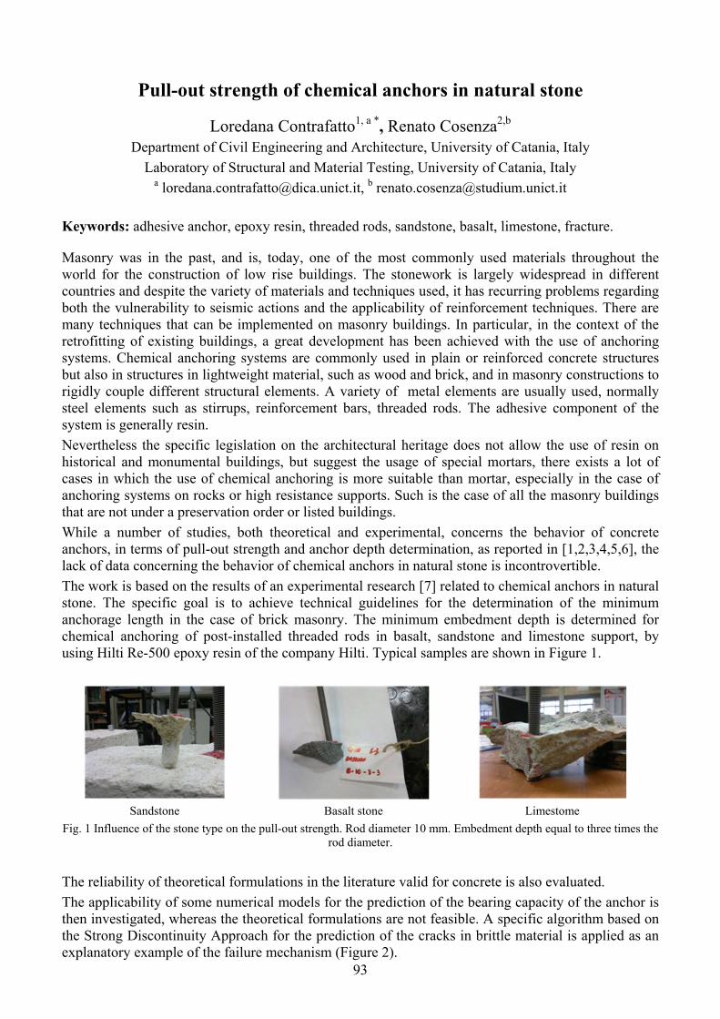
93
Pull-out strength of chemical anchors in natural stone
Loredana Contrafatto1, a *, Renato Cosenza2,b Department of Civil Engineering and Architecture, University of Catania, Italy
Laboratory of Structural and Material Testing, University of Catania, Italy a [email protected], b [email protected]
Keywords: adhesive anchor, epoxy resin, threaded rods, sandstone, basalt, limestone, fracture.
Masonry was in the past, and is, today, one of the most commonly used materials throughout the world for the construction of low rise buildings. The stonework is largely widespread in different countries and despite the variety of materials and techniques used, it has recurring problems regarding both the vulnerability to seismic actions and the applicability of reinforcement techniques. There are many techniques that can be implemented on masonry buildings. In particular, in the context of the retrofitting of existing buildings, a great development has been achieved with the use of anchoring systems. Chemical anchoring systems are commonly used in plain or reinforced concrete structures but also in structures in lightweight material, such as wood and brick, and in masonry constructions to rigidly couple different structural elements. A variety of metal elements are usually used, normally steel elements such as stirrups, reinforcement bars, threaded rods. The adhesive component of the system is generally resin.
Nevertheless the specific legislation on the architectural heritage does not allow the use of resin on historical and monumental buildings, but suggest the usage of special mortars, there exists a lot of cases in which the use of chemical anchoring is more suitable than mortar, especially in the case of anchoring systems on rocks or high resistance supports. Such is the case of all the masonry buildings that are not under a preservation order or listed buildings.
While a number of studies, both theoretical and experimental, concerns the behavior of concrete anchors, in terms of pull-out strength and anchor depth determination, as reported in [1,2,3,4,5,6], the lack of data concerning the behavior of chemical anchors in natural stone is incontrovertible.
The work is based on the results of an experimental research [7] related to chemical anchors in natural stone. The specific goal is to achieve technical guidelines for the determination of the minimum anchorage length in the case of brick masonry. The minimum embedment depth is determined for chemical anchoring of post-installed threaded rods in basalt, sandstone and limestone support, by using Hilti Re-500 epoxy resin of the company Hilti. Typical samples are shown in Figure 1.
Sandstone Basalt stone Limestome
Fig. 1 Influence of the stone type on the pull-out strength. Rod diameter 10 mm. Embedment depth equal to three times the rod diameter.
The reliability of theoretical formulations in the literature valid for concrete is also evaluated.
The applicability of some numerical models for the prediction of the bearing capacity of the anchor is then investigated, whereas the theoretical formulations are not feasible. A specific algorithm based on the Strong Discontinuity Approach for the prediction of the cracks in brittle material is applied as an explanatory example of the failure mechanism (Figure 2).

94
Fig. 2 SDA simulation of the failure mechanism.
References
[1] A. H. Nilson, Internal Measurement of Bond Slip, ACI Structural Journal. 69 (1972) 439-441.
[2] R. A. Cook, Behavior of chemically bonded anchors, Journal of Structural Engineering. 119 (1993) 2744-2762.
[3] R. A. Cook, R. C. Konz, Factors Influencing Bond Strength of Adhesive Anchors, ACI Structural Journal. 98 (2001) 76-86.
[4] A. Colak, Parametric study of factors affecting the pull-out strength of steel rods bonded into precast concrete panels, International Journal of Adhesion & Adhesives. 21 (2001) 487-493.
[5] T. S. Bickel, A. Fattah Shaikh, Shear Strength of Adhesive Anchors, PCI Journal. Sept-Oct (2002) 92-102.
[6] R. Eligehausen, R. A. Cook, J. Appl, Behavior and Design of Adhesive Bonded Anchors, ACI Structural Journal. 103 (2006) 822-831.
[7] L. Contrafatto, R. Cosenza, Experimental behaviour of post-installed adhesive anchors in natural stone, submitted to Construction and Building Materials, (2014).
95
Strain gradient elasticity within the symmetric BEM formulation
S. Terravecchia1,a* , T. Panzeca2,b and C. Polizzotto3,c 1,2,3 DICAM, Viale delle Scienze, 90128 Palermo, Italy
a [email protected], b [email protected], c [email protected]
Keywords: Strain gradient elasticity, Symmetric Galerkin BEM.
The symmetric Galerkin Boundary Element Method is used to address a class of strain gradient elastic materials featured by a free energy function of the (classical) strain and of its (first) gradient. With respect to the classical elasticity, additional response variables intervene, such as the normal derivative of the displacements on the boundary, and the work-coniugate moment tractions. The fundamental solutions - featuring a fourth order partial differential equations (PDEs) system - exhibit singularities which in 2D may be of the order 41 / r .
This research communication shows a part of the results being elaborated within a more general paper [1].
After the pioneering work of Mindlin [2], theories of strain gradient elasticity have become very popular, particularly within the domain of nano-technologies, that is, for problems where the ratio surface/volume tends to become very large and there is a need to introduce at least one internal length.
However the model introduced by Mindlin and then improved by Mindlin et al. [3] and Wu [4] leads to an excessive number of material coefficients, which at the best for isotropic materials reduce to the number of seven. In the early 1990, Aifantis [5] introduced a signified material model of strain gradient elasticity which requires only three material coefficients, that is, the Lame' constants and one length scale parameter. The latter model was then developed further following the so-called Form II format given by Mindlin et al. [3], that is a theory centered on the existence of a free energy functions of the (classical) strain and of its first gradient, which leads to the generation of symmetric stress fields (see Askes et al. [6] for historical details about the latter formulations and its applications).
Formulations in the boundary element method based on the strain gradient elasticity were pioneered by Polyzos et al. [7], Karlis et al. [8] who provide a collocation BEM formulation where the simplified constitutive equation by Aifantis [5] has been adopted. In latter papers only the fundamental solutions used in the collocation approach to BEM are provided.
In the case of the symmetric formulation of the BEM, Somigliana Identities (SIs) for the tractions and for the double tractions are also needed. These new SIs are necessary in order to get, through the process of modeling and weighing, a solving equation system having symmetric operators. In Polizzotto et al. [1] all the set of fundamental solutions is derived starting from the displacement fundamental solution given in [7,8].
The symmetric formulation is motivated by the high efficiency achieved within classical elasticity by the method in [9] with regard to the techniques used to eliminate the singularities of the fundamental solutions, the evaluation of the coefficients of the solving system and the computational procedures characterized by great implementation simplicity. This has already led to the birth of the computer code Karnak sGbem [10] operating in the classical elasticity.
The objective of this paper is to experiment new techniques and procedures that, applied in the context of strain gradient elastic materials, may permit one to obtain the related solving system.
The class of strain gradient elastic materials herein considered is featured by the following strain elastic energy
21
: : :: ( )2 2
TW ε E ε E ε ε
(1)

96
where is the internal length, ( )S ε u is the classical strain and E is the classic isotropic elasticity tensor. Eq. (1) provides the "primitive" stresses
(0) (1) 2 2 (0); σ E ε σ σ (2)
The constitutive equation relating the total stress σ to the strain is
2 2 ) σ E : (ε ε (3)
where ε is the classical strain.
In [7,8] the fundamental solution of the displacements for 2D solids is obtained through which, using the well-known procedure given in [11], it is possible by exploiting the known properties of symmetry of the fundamental solutions to derive the entire tableau of the fundamental solutions.
Computational techniques have been pursued in order to eliminate the singularities of order 1 / r , 21/ r , in the blocks of the coefficients related to the corners of the solid and new techniques based on
the rigid motion strategy have been introduced in order to test the coefficients of the blocks of the solving system. The displacement and internal deformation fields were obtained.
Numerical techniques in order to remove the singularity of higher order like 31/ r and 41/ r are in advanced study.
References
[1] C. Polizzotto, T. Panzeca, S. Terravecchia, A symmetric Galerkin BEM formulation for a class of gradient elastic materials of Mindlin type. Part I: Theory, (2014) in preparation. [2] R.D.Mindlin, Second gradient of strain and surface tension in linear elasticity, Int. J. Solids Struct. 1 (1965) 417-438. [3] R.D. Mindlin, N.N. Eshel, On first strain-gradient theories in linear elasticity, Int. J. Solids Struct. 28 (1968) 845-858. [4] C.H. Wu, Cohesive elasticity and surface phenomena, Quart. Appl. Math. L(1) (1992) 73-103. [5] E.C. Aifantis, On the role of gradients in the localization of deformation and fracture,. Int. J. Eng. Sci. 30 (1992) 1279-1299. [6] H. Askes, E.C. Aifantis, Gradient elasticity in statics and dynamics: An overview of formulations, length scale identification procedures, finite element implementations and new results, Int. J. Solids Struct. 48 (2011) 1962-1990. [7] D. Polyzos, K.G. Tsepoura, S.V. Tsinopoulos, D.E. Beskos, A boundary element method for solving 2-D and 3-D static gradient elastic problems. Part.I: integral formulation, Comput. Meth. Appl. Mech. Engng. 192 (2003) 2845-2873. [8] G. F. Karlis, A. Charalambopoulos, D. Polyzos, An advanced boundary element method for solving 2D and 3D static problems in Mindlin's strain gradient theory of elasticity, Int. J. Numer. Meth. Engng. 83 (2010) 1407-1427. [9] T. Panzeca, F. Cucco, S. Terravecchia, Symmetric Boundary Element Method versus Finite Element Method, Comp. Meth. Appl. Mech. Engrg. 191 (2002) 3347-3367. [10] F. Cucco, T. Panzeca, S. Terravecchia, The program Karnak.sGbem Release 2.1, Palermo University (2002). [11] C. Polizzotto, An energy approach to the boundary element method. Part.I: elastic solids, Comput. Meth. Appl. Mech. Engng. 69 (1988) 167-184.

97
Multidomain Symmetric Galerkin BEM for non-linear analysis of masonries in-plane loaded
L. Zito1,a*, S. Terravecchia2,b and T. Panzeca3,c 1,2,3 DICAM, Viale delle Scienze, 90128 Palermo, Italy
a [email protected], b [email protected], c [email protected]
Keywords: Multidomain SGBEM, Displacement approach, Masonries.
The preservation of the historical and monumental buildings, but also of the considerable heritage of old constructions made by traditional techniques, is one of the actual problems of the structural mechanics. The level of knowledge of their structural behavior in presence of external actions is made through calculus methods and simple procedures in order to allow a reading of the material suffering degree and as a consequence of the related safety.
In this paper an elastic analysis of walls, also in presence of geometrical nonlinearity consisting in the contact/detachment phenomenon among stone blocks. The wall having any shape and zone-wise variable physical characteristics is loaded in its plane. For these structures some interventions of structural strengthening have as aim to improve the wall behavior by reducing the stress concentration, so to have a better safety in comparison with its initial value.
Among the more considerable aspects within the protection of the masonry buildings, and in particular of the historical and monumental patrimony, there is the identifying of the static instability causes found in the walls. The difficulties in studying these structural systems depend on several elements, as the complexity of structural behavior and the uncertainties in the physical-mechanical characterization of the materials.
At same time, the choice of the interventions in order to guarantee the safety wanted, respectful of the rules of the restoration, is full of dangers. Often the architect or engineer uses empiric rules, also supported by rough structural schematizations, attaining to solutions often not answering to the necessary safety of the building.
As a consequence the use of the calculus code supported by appropriate computational methodologies is necessary to make numerical simulations which, once known the external actions, have the aim:
- to identify the possible causes of the instabilities through the solution of an inverse problem;
- to perform interventions on masonry panels, having feature of prevention towards possible static instabilities;
- to establish what, among the technical solutions of intervention to be activated, is this more appropriate, by making a comparison among different solutions of reinforcement.
The aim is to increase the safety conditions of the masonry buildings through the improving the stiffness of each wall panel in order to reach a global structural response with a more uniform field of the stress state.
In this paper the analysis is performed in the hypotheses that the actions (boundary and body forces, displacements of the constraint) act in the plane of each panel. It can be made through numerical simulations using analysis methodologies able to perform the necessary checks within reduced calculus times.
The usual calculus codes employed to analyze the masonries have as theoretical basis the Finite Element Method (FEM). But this method shows several drawbacks meanly connected to the discretization employed in the walls, usually foreseeing the use of elements having the same geometry.
The present paper suggests an innovative analysis based on the use of a multidomain strategy within the symmetric Galerkin formulation of the Boundary Element Method (SGBEM).

98
Within the SGBEM, in this paper, a strategy which uses the displacement method, proposed by Panzeca et al. [1, 2], is utilized. The latter method shows symmetry of the algebraic operators and is characterized as follows:
a) the subdivision of each masonry panel by substructures having any shape and dimension and different physical properties;
b) the boundary distinction of each substructure into constrained, free and interface with other substructures;
c) the writing of a characteristic elasticity equation for each substructure connecting weighted tractions evaluated on the interface boundary to nodal displacements of the same interface and to the load vector;
d) the use of the equation system through the writing of the compatibility strong form at the interface nodes and through the related weak form involving weighted (or generalized) tractions at the interface boundary elements,
e) the computation in closed form of all the double integrals making up the equation system coefficients, having hypersingular, singular or regular kernels [3],
f) permit the transformation of the domain integrals into boundary ones. The reader can refer to Panzeca et al. [4].
The discretization of the panel into substructures can be made through its subdivision into macrozones characterized by a homogenization of the physical parameters of the stone-mortar system and single elements constituting the panel as stone blocks and mortar layers, possibly considered separately.
The simultaneous use of the two different levels of discretization, one more sparse in macrozones and another more dense, is characteristic of the potenziality of the method. The presence of substructures having big or small dimensions does not involve numerical instabilities because all the coefficients of the equation system were computed in closed form.
The analysis of the masonry is made by using the Karnak.sGbem code [5]. This program allows to evaluate the response of the structural system subjected to all the possible static actions, whether volumetric or surface loads, but also to volumetric and linear distortions and to displacements imposed in the constraints.
Besides, it is possible to make a nonlinear analysis of cohesive detachment, so reproducing the evolution of the probable disconnectedness between stones through a strategy developed by some authors [6].
References
[1] T. Panzeca, F. Cucco, S. Terravecchia, Symmetric boundary element method versus finite element method. Comput. Methods Appl. Mech. Engrg. 191 (2002) 3347-3367. [2] T. Panzeca, M. Salerno, S. Terravecchia, Domain decomposition in the symmetric boundary element method analysis. Comput. Mech. 28 (2002) 191-201. [3] M. Bonnet, Regularized direct and indirect symmetric variational BIE formulation for three-dimensional elasticity. Eng. Anal. Boundary Elem. 15 (1995) 93-102. [4] T. Panzeca, S. Terravecchia, L. Zito, Computational aspects in 2D SBEM analysis with domain inelastic actions. Int. J. Numer. Meth. Engng. 82 (2010) 184-204. [5] F. Cucco, T. Panzeca, S. Terravecchia, Karnak.sGbem. Release 1.0, www.bemsoft.it, Palermo 2002. [6] T. Panzeca, M. Salerno, S. Terravecchia, L. Zito, The symmetric Boundary Element Method for unilateral contact problems. Comput. Methods Appl. Mech. Engrg. 197 (2008) 2667-2679.

99
SOMMARI
GMA Gruppo Materiali
AIMETA
Congresso GIMC-GMA-2014 11-13 giugno 2014

100

101
Sorption of low molecular weight compounds in polymers: thermodynamic issues and plasticization effects
Giuseppe Mensitieri1,a *, Giuseppe Scherillo1,b and Pellegrino Musto2,c 1 Dept. of Chemical, Materials and Production Engineering
University of Naples Federico II, P.le Tecchio 80, 80125, Italy 2 Institute for Polymers, Composite and Biomaterials
National Research Council of Italy, Viale Campi Flegrei 34, 80078 Pozzuoli (Na), Italy [email protected], [email protected], [email protected]
* corresponding author
Keywords: Sorption Thermodynamics; Low molecular weight compounds; Compressible lattice fluid, Glassy polymer; Rubbery Polymer
Introduction
Sorption and transport of low molecular weight compounds is a key issue in assessing the durability of polymer matrix composites. In fact, absorbed compounds (water, solvents, high pressure gases) can adversely affect mechanical properties of the matrix and fiber-matrix interface integrity. In this contribution, the general issue of sorption thermodynamics and mass transport of low m.w. penetrants in glassy and rubbery polymers is addressed providing a consistent thermodynamic interpretation of the experimental investigations, accounting also for the effects of possible self- and cross-hydrogen bonding interactions. In particular, the analysis of water and methanol sorption in polyimides, polyetherimide, polyetheretherketone and in polycaprolactone are presented.
Sorption thermodynamics
Interpretation of sorption thermodynamics in rubbery polymers is here approached by using a lattice fluid theory accounting also for the effect of possible self- and cross-interactions (hydrogen bonding) in polymer–penetrant systems, the so called ‘Non Random lattice fluid Hydrogen Bonding’ (NRHB) model [1, 2]. Thermodynamic models accounting for both interactions and non-equilibrium nature of glassy polymers have been proposed only recently [3]. In fact, physical properties of glassy polymers significantly differ from those of the same polymer in the rubbery state. Consistently, also sorption thermodynamics differ substantially and modeling should properly account for non-equilibrium state. To this aim, a successful approach is provided by a theoretical framework developed to extend the equilibrium mixture theories suitable for rubbery polymers to the non-equilibrium glassy polymer-penetrant mixtures (the so-called Non-Equilibrium Thermodynamics for Glassy Polymers, NETGP) by introducing internal state variables, which act as order parameters quantifying the departure from the equilibrium conditions at fixed pressure and temperature [4]. In the present contribution, we have applied this procedure to extend NRHB theory to non-equilibrium glassy systems [3] to provide a suitable model (NETGP-NRHB) for interpretation of sorption of interacting penetrants in glassy polymers.
Experimental analysis Gravimetric and vibrational spectroscopy experiments have been performed. The former provides information on the total mass of sorbed penetrant (sorption isotherms) while the latter provides qualitative and quantitative information regarding the ‘state’ of penetrant molecules within the polymer matrix, with particular reference to the interactions which are established with macromolecules. Results of in situ FTIR spectroscopy on rubbery and glassy polymers exposed to penetrants vapour at different pressures have been analyzed by 2D correlation spectroscopy to improve the resolution by spreading the data over a second frequency axis providing, at the same time, information about the dynamics of the evolving system [5]. The results of experimental analyses are compared with predictions of NRHB and NETGP-NRHB models, respectively for the case of rubbery and glassy polymers. As an example, the results of spectroscopic analysis of water sorption in 6FDA-
Invited Lecture

102
ODA polyimide (2 F atoms per repeating unit, Tg = 308°C) are reported in figure 1. The whole of the 2D results (figure 1, left) points to the occurrence of two distinct water species. Likely structures for the H-bonding aggregates are reported in figure 1, right. In figure 2 is, instead. shown, for the same system, the capability of the NETGP-NRHB model to rovide good quantitative estimates of the different kinds of water species present in the system.
Figure 1: Left:2D-FTIR correlation spectra (asynchronous) obtained from the time-resolved spectra collected during water
sorption in 6FDA-ODA polyimide at a relative pressure = 0.6. Right : Schematic representation of the H-bonding interactions in the investigated water/PI system
Figure 2: Comparison of predictions of NETGP−NRHB model with experimental results for 6FDA-ODA: moles of water
self-HBs wp11(n ) and moles of hydrogen bonding between absorbed water molecules and proton acceptor groups on the
polymer backbone wp12(n ) per gram of dry polymer as a function of water mass fraction in the polymer/water mixture.
References
[1] C. Panayiotou, I. Tsivintzelis, I.G.Economou, Nonrandom hydrogen-bonding model of fluids and their mixtures. 2. Multicomponent mixtures Ind. Eng. Chem. Res., 46 (2007) 2628-2636.
[2] I. Tsivintzelis, G.M. Kontogeorgis, Modeling the vapor-liquid equilibria of polymer-solvent mixtures: Systems with complex hydrogen bonding behavior Fluid Phase Equilib., 280 (2009) 100-109.
[3] G. Scherillo, L. Sanguigno, M. Galizia, M. Lavorgna, P. Musto and G. Mensitieri, Non-equilibrium compressible lattice theories accounting for hydrogen bonding interactions: Modelling water sorption thermodynamics in fluorinated polyimides Fluid Phase Equilibria, 334 (2012) 166-188.
[4] F. Doghieri, G. C. Sarti, Nonequilibrium lattice fluids: A predictive model for the solubility in glassy polymers Macromolecules, 29 (1996) 7885-7896.
[5] P. Musto, G. Mensitieri, M. Lavorgna, G. Scarinzi, G. Scherillo, Combining Gravimetric and Vibrational Spectroscopy Measurements to Quantify First- and Second-Shell Hydration Layers in Polyimides with Different Molecular Architectures J. Phys. Chem. B, 116 (2012) 1209−1220.

103
Propagation of elastic waves and generation of band-gaps in diffusively damaged structures
Giorgio Carta1, 2, a *, Michele Brun1, 2,b and Alexander B. Movchan2,c 1 Dipartimento di Ingegneria Meccanica, Chimica e dei Materiali, Università di Cagliari, Italy
2 Department of Mathematical Sciences, University of Liverpool, UK [email protected], [email protected], [email protected]
Keywords: elastic waves; damaged structures; cracks; dispersion curves; band-gaps.
Discontinuities in homogeneous elastic solids generate band-gaps, that are ranges of frequencies for which waves do not propagate. Such discontinuities may be represented by cross-section reductions due to cracks or to design choices. For instance, in multi-span simply-supported bridges the connection between two adjacent spans is usually constituted by the upper deck; therefore, in correspondence of the connection the bridge possesses a lower cross-section.
The dynamic behaviour of an elastic solid with equispaced cracks is discussed [1]. The solid is firstly studied as a two-dimensional strip, and the propagation of transverse waves is examined. It is shown that the eigenfrequencies of finite strips with different lengths fall inside the propagation bands of infinite strips with periodically-distributed cracks. In addition, we consider different boundary conditions at the ends of finite strips of different dimensions.
The two-dimensional damaged strip is also analysed as a beam with elastic junctions [1]. The latter simulate the cracked cross-sections and are characterised by a rotational (bending) and a translational (shear) spring. The stiffnesses (per unit thickness of the beam) of the two springs are derived by means of a static asymptotic analysis [2] and are given respectively by
2π
4 5 2 1b
EK
(1)
and
2
π
4 1 log /s
EK
h
, (2)
where E is Young's modulus, ν is Poisson's ratio, while ρε and h are the depths of the cracked and intact cross-sections. The dispersion curves of the beam reproduce well the propagation bands of the two-dimensional strip in the low- and medium-frequency ranges, as shown in Figure 1. In the axes of this figure, k l is the product of the wavenumber and the distance between the cracks, while is a non-dimensional parameter related to the radian frequency. It is proved that the limits of the band-gaps coincide with the eigenfrequencies of simple beams with appropriate boundary conditions [1]. Moreover, we investigate the effect of changing the slenderness of the strip on the efficiency of the beam model.

104
Figure 1: Comparison between the dispersion curves of an infinite beam (solid grey lines) and of an infinite strip (dots),
both with periodically-distributed cracks and characterised by the following properties: E = 200 GPa, ν = 0.3, mass density ρ = 7800 kg/m3, h = 0.2 m, ρε = 0.04 m.
The outcomes of this work may be useful in the context of Structural Health Monitoring for the detection of damages and defects in structures. Furthermore, they could be exploited to design structures with appropriate discontinuities (e.g. reduced cross-sections) that can filter waves of specified frequencies. Finally, we point out that it still remains a challenge to study the dynamic response of a solid with randomly-spaced cracks or defects.
References
[1] G. Carta, M. Brun, A.B. Movchan, Dynamic response and localisation in strongly damaged waveguides, Proc. R. Soc. A, accepted for publication.
[2] M. Gei, I.S. Jones, A.B. Movchan, Junction conditions for cracked elastic thin solids under bearing and shear, Quart. J. Mech. Appl. Math. 62 (2009), 481-493.
105
On the compressive strength of glass-microballoons/thermoset-matrix syntactic foams
Lorenzo Bardella1, a * and Andrea Panteghini2,b 1DICATAM, University of Brescia, via Branze 43, 25123, Brescia, Italy 2DICATAM, University of Brescia, via Branze 43, 25123, Brescia, Italy
[email protected], [email protected]
* corresponding author
Keywords: Syntactic foam; Glass microballoon; Computational homogenization; Finite element modeling; Strength; Thermoset matrix composites.
This work is concerned with particulate composites filled with hollow spherical inclusions, i.e., syntactic foams. We propose a micromechanical model to evaluate the uniaxial compressive strength for the most relevant case of glass inclusions of wall thickness of few micrometers (microballoons) filling a thermoset matrix. The studied failure modality is experimentally characterised by shear bands inclined of about 45 degress with respect to the loading axis, and a prominent softening behaviour. We develop a three-dimensional Finite Element (FE) modelling which extends and improves that recently proposed by our group [1,2]. Different microstructures are described by cubic unit cells containing fifty hollow spheres accounting for different filler polydispersions and filler volume fraction up to 60%. Each microballoon is assumed to undergo brittle failure according to a structural criterion. Here, we account for the matrix nonlinear behaviour and, in a phenomenological way, for the detriment of its mechanical properties, proportional to its defectiveness, which increases with the filler content and becomes extremely relevant at filler volume fraction larger than 50%. Our findings agree with experimental observations from the literature and reveal room for improvement in the effective mechanical properties by acting on the manufacturing process.
References
[1] L. Bardella, A. Sfreddo, C. Ventura, M. Porfiri, N. Gupta, A critical evaluation of micromechanical models for syntactic foams, Mech. Mater. 50 (2012) 53-69.
[2] L. Bardella, F. Malanca, P. Ponzo, A. Panteghini, M. Porfiri, A micromechanical model for quasi-brittle compressive failure of glass-microballoons/thermoset-matrix syntactic foams, J. Eur. Ceram. Soc. (2014) in print, DOI: 10.1016/j.jeurceramsoc.2013.11.045.
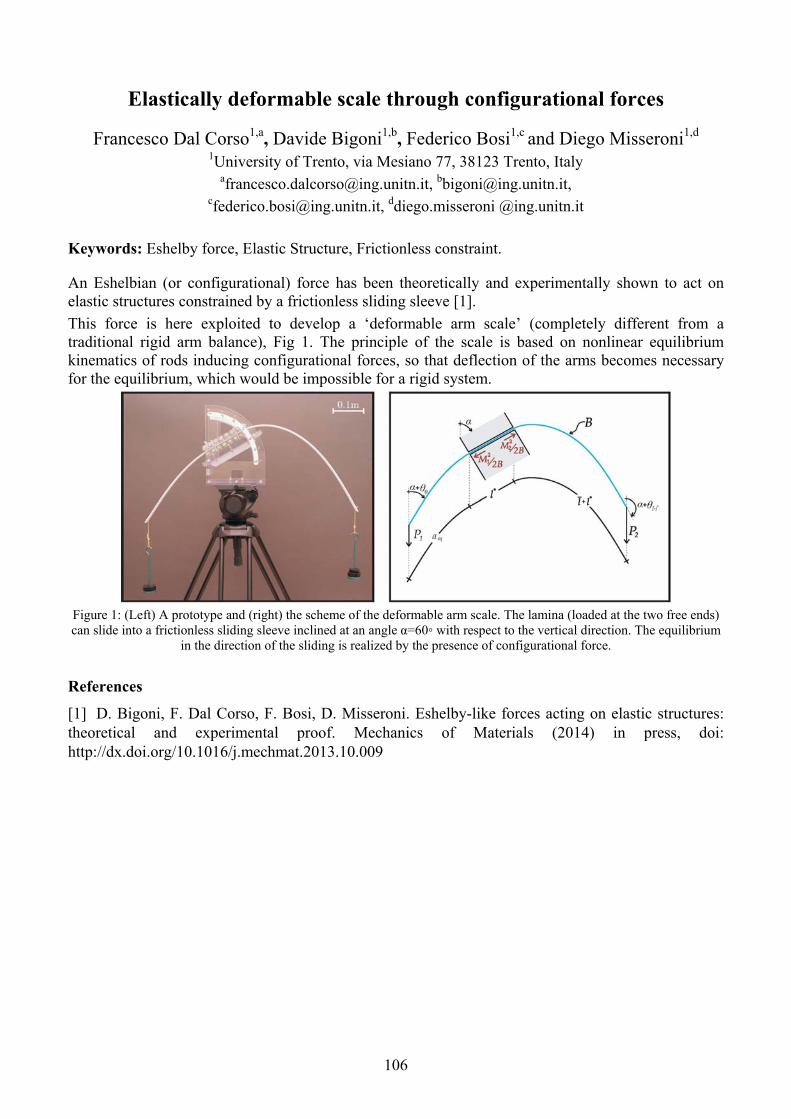
106
Elastically deformable scale through configurational forces
Francesco Dal Corso1,a, Davide Bigoni1,b, Federico Bosi1,c and Diego Misseroni1,d 1University of Trento, via Mesiano 77, 38123 Trento, Italy
[email protected], [email protected], [email protected], ddiego.misseroni @ing.unitn.it
Keywords: Eshelby force, Elastic Structure, Frictionless constraint.
An Eshelbian (or configurational) force has been theoretically and experimentally shown to act on elastic structures constrained by a frictionless sliding sleeve [1].
This force is here exploited to develop a ‘deformable arm scale’ (completely different from a traditional rigid arm balance), Fig 1. The principle of the scale is based on nonlinear equilibrium kinematics of rods inducing configurational forces, so that deflection of the arms becomes necessary for the equilibrium, which would be impossible for a rigid system.
Figure 1: (Left) A prototype and (right) the scheme of the deformable arm scale. The lamina (loaded at the two free ends) can slide into a frictionless sliding sleeve inclined at an angle α=60 with respect to the vertical direction. The equilibrium
in the direction of the sliding is realized by the presence of configurational force.
References
[1] D. Bigoni, F. Dal Corso, F. Bosi, D. Misseroni. Eshelby-like forces acting on elastic structures: theoretical and experimental proof. Mechanics of Materials (2014) in press, doi: http://dx.doi.org/10.1016/j.mechmat.2013.10.009
107
Flaw-tolerance of nonlocal discrete systems and interpretation according to network theory
Andrea Infuso1, a *, Marco Paggi2,b 1Politecnico di Torino, C.so Duca degli Abruzzi 24, 10129 Torino, Italy
2IMT Institute for Advanced Studies, P.zza San Francesco 19, 5510 Lucca, Italy [email protected], [email protected]
Keywords: nonlocality, discrete systems, MDFEM, network theory, numerical methods.
Nonlocal continuum theories based on gradient models, integral formulations or fractional calculus have been widely explored in mechanics to describe long-range interactions (see, e.g., [1-4] among the most recent contributions on this topic). At the same time, discrete systems composed of particles or molecules have been proposed in the physics community to analyze the behavior of materials. Lattice beam models [5], albeit suffering from mesh dependency due to the local nature of the bonds/links, have been extensively used to simulate the meso-scale behaviour of concrete. Efforts accounting for nonlocal effects, such as the three-dimensional Born model [6], have bee proposed to study the distribution of broken bonds within a homogeneous discrete mechanical system. With the progress in computer technology, wide tri-dimensional discrete systems can nowadays be modeled by molecular dynamics (MD), accounting for nonlinear interatomic potential laws and nonlocal interactions among the discrete molecules. Attempts to couple MD with FEM have also been explored [7]. In this study, the focus regards the analysis of the ability of nonlocal molecular discrete systems to tolerate flaws. To this aim, nonlinear springs whose constitutive relation is ruled by the van der Waals potential are implemented in the finite element analysis programme FEAP. The tensile and compressive responses of 1D and 2D discrete systems of molecules with or without flaws are numerically simulated, by varying the range of nonlocal interactions. For each system, the statistical distribution of the force field at different load levels is carefully analyzed in relation to the topological properties of the underlying network, in order to understand the force redistribution mechanisms occurring in nonlocal discrete systems in the presence of defects.
References
[1] M. Di Paola, M. Zingales, Long-range cohesive interactions of non-local continuum faced by fractional calculus, International Journal of Solids and Structures, 45 (2008) 5642-5659.
[2] A. Carpinteri, P. Cornetti, A. Sapora, M. Di Paola, M. Zingales, Fractional calculus in solid mechanics: Local vs Non-Local Approach, Physica Scripta, T136 (2009) 014003-014010.
[3] M. Di Paola, F. Marino, M. Zingales, Integral and fractional model of elastic foundation based on long-range interactions, International Journal of Solids and Structures 46 (2009) 3124-3117.
[4] M. Di Paola, G. Failla, M. Zingales, Physically based approach to the mechanics of strong non-local linear elasticity theory, Journal of Elasticity, 97 (2009) 103-130.
[5] J.G.M. van Mier, E. Schlangen, A. Vervuurt, Lattice type fracture models for concrete, H.B. Mühlhaus (Ed.), Continuum Models for Materials with Microstructure, John Wiley & Sons, 1995, pp. 341-377.
[6] A. Parisi, G. Caldarelli, L. Pietronero, Roughness of fracture surfaces, Europhysics Letters, vol. 52 (3), (2000), pp. 304-310.
[7] L. Nasdala, A. Kempe, R. Rolfes, The molecular dynamic finite element method (MDFEM), Computer, Materials & Continua 19 (2010) 57-104.

108
A model to interpret the wedge-shaped spalling in pull-out tests of FRP from concrete
Roberto Ballarini1, a, Annalisa Franco2,b* and Gianni Royer Carfagni2,c 1Department of Civil Engineering, University of Minnesota, 500
Pillsbury Drive S.E. Minneapolis, MN 55455-0116, USA 2Department of Industrial Engineering, University of Parma,
Parco Area delle Scienze 181/A, I 43100 Parma, Italy [email protected], [email protected], [email protected]
Keywords: Fiber Reinforced Polymer (FRP); stiffener; pull-out test; substrate cracking; inclined crack propagation; elasticity; complex potential; distributed dislocations.
Fiber-Reinforced-Polymer (FRP) materials are commonly used to repair and refurbish buildings and bridges by gluing strips or plates to the external surfaces of concrete structural elements in order to increase their bending strength. Pull-out tests on FRP joints have provided a wealth of evidence that the dominant failure mode is debonding, occurring a few millimeters underneath the adhesive interface. The failure is characterized by the formation of a process zone, which nucleates at the loaded end of the stiffener, where a relative slip between stiffener and substrate occurs at non-zero shear stress. During the pull-out test, such zone progresses in a stable way until it reaches a critical length, coinciding with the effective bond length of the bonded joint, which marks the start of debonding. Pulling further, delamination propagates and the cohesive zone simply translates towards the free end of the joint until a softening phase begins [1]. The final failure occurs when the FRP stiffener completely separates from the substrate. Remarkably, such a stage is characterized by the initiation of an inclined crack at the free end of the stiffener, penetrating into the substrate. The subsurface crack produces a characteristic wedge-shaped spall (Figure 1).
Figure 1: Wedge-shaped spall of the substrate in FRP-to concrete bonds with different initial bond lengths, as per [2].
Initial bond length: a) l = 30 mm, b) l = 90 mm; c) l = 150 mm.
There is not unanimous consensus on the reasons for the transition from cracking along the bond to cracking within the substrate. Here, a linear elastic fracture mechanics model problem is presented that provides improved understanding of the formation of the subsurface crack. The stiffener is assumed to transmit shear stresses to a substrate modeled as a homogeneous isotropic elastic half-plane in generalized plane stress. Therefore, the formulation of the propagation of a crack at the free end of the stiffener relies on the superposition of two effects: i) the effect of tangential forces per unit area on the surface of the half plane and ii) the effect of distributed edge dislocations along the crack. The condition that the crack surfaces are traction-free furnishes an integral equation, which is solved using the properties of Chebyshev polynomials.
In order to comprehend the transition between the interface delamination and the substrate cracking, two competing mechanisms of degradation are considered; a) failure of the adhesive joint, which progresses at the stiffener-substrate interface when the corresponding shear stress is greater than the

109
strength of the interface, say q0; b) inclined cracking, which can develop in the substrate when the strain energy release associated with its propagation, *
,nG , is greater than the corresponding fracture
energy of the material. A key hypothesis for this model is that fracture does not progress continuously and uniformly, but in discrete steps. In other words, there is a quantized length for crack propagation, namely a*, that is comparable to the characteristic dimensions of the material microstructure. Therefore *
,nG must be interpreted as the quantized energy release rate corresponding
to an increase a* of crack length. From the competition between the two mechanisms, with the same rationale proposed by [3], one can evaluate when the inclined crack starts to form and the characteristic angle of the wedge-shaped bulb. In particular, the inclined crack becomes energetically more favorable as soon as
* 2, 0 / 1nG q . (1)
When * 2, 0 / 1nG q propagation along the interface (debonding) occurs first.
For the same material parameter of [2], Figure 2 shows the ratio
* 2, 0 /nG q as a function of the
crack inclination angle ω for different values of a*. The value
* 2, 0 / 1nG q defines the limit case
that separates the two different damage mechanisms. For any a*, one can evaluate the limit angle ω which marks the transition from one damage mechanism to the other [4].
In general, the quantum length a* is associated with the material intrinsic length scale that, for conglomerates like concrete, is correlated with the average size of the aggregate. For the tests of [2], one can conveniently consider a* = 10-15 mm. With this choice, the critical angle ω varies in the
interval 24-31°. From the pictures of Figure 1, it is evident that the concrete wedges are defined by angles comprised in the interval 18-33°, in good agreement with the prediction of this approach.
References
[1] A. Franco, G. Royer-Carfagni, Cohesive debonding of a stiffener from an elastic substrate. Comp. Struct. 111 (2014) 401–414.
[2] P. Carrara, D. Ferretti, F. Freddi, G. Rosati, Shear tests of carbon fiber plates bonded to concrete with control of snap-back. Eng. Fract. Mech. 78 (2011) 2663 – 2678.
[3] J. Willis, A comparison of the fracture criteria of Griffith and Barenblatt. J. Mech. Phys. Solids 15 (1967) 151 – 162.
[4] R. Ballarini, A. Franco, G. Royer-Carfagni, Wedge-shaped fracturing in the pull out of FRP stiffeners from quasi-brittle substrates, submitted to Int. J. Solids Struct. (2014).
Figure 2: Normalized strain energy release as a function of the inclination angle ω for different values of the crack quantum length a∗ (mechanical parameters of [2], bond length l = 30 mm, q0 = τc).
0 10 20 30 40 50 60 70 80 900
0.2
0.4
0.6
0.8
1
1.2
1.4
1.6
1.8
2
Inclination angle, ω [°]
G* ω
,n τ
c2 / Γ
a*= 1 mm
a*= 2 mm
a*= 5 mm
a*= 7 mm
a*= 10 mm
a*= 12 mm
a*= 15 mm
a*= 20 mm
G*ω,n
τc2 / Γ=1
110
Morphoelastic rods
Alessandro Tiero1,a, Giuseppe Tomassetti1,b * 1Universita` di Roma Tor Vergata
Dipartimento di Ingegneria Civile e Ingegneria Informatica Via Politecnico 1 00133 Roma - Italy
[email protected], [email protected]
* Corresponding author
Keywords: growth, remodeling, thin structures, configurational forces, material forces.
Unlike common engineering materials, living matter can adapt to environmental changes by growing and by actively modifying its structure. When trying to accommodate these features in the infrastructure of continuum mechanics, a key issue is to distinguish growth from strain. Beginning with [1], this issue has been addressed through a multiplicative decomposition f FGof the deformation gradient into a part F accounting for mechanically-induced strain, and a part G accounting for growth.
The additional degrees of freedom brought in by the growth tensor G demand additional evolution laws whose choice and interpretation set a formidable challenge. In the format set forth in [2] the laws governing the evolution of the growth tensor are obtained by combining suitable constitutive prescriptions with a balance equation for a system of remodeling couples which expend power over temporal changes of G. An appropriate version of the dissipation principle yields that the energetic part of the inner remodeling couple coincides with the Eshelby stress E ψI F S, a tensorial quantity introduced by Eshelby [3] in its discussion of a force acting on a material defect.
For a thin body, such as a rod, one may ask what is the equivalent of the standard multiplicative decomposition and what mechanical statement should take the place of the Eshelby stress. In [4] we provide a possible answer by deriving a theory describing elastic rods which, like plant organs, can grow and can change their intrinsic curvature and torsion. The equations ruling accretion and remodeling are obtained by combining balance laws involving non-standard forces with constitutive prescriptions filtered by a dissipation principle that takes into account both standard and non-standard working. In this theory, the Eshelby stress is replaced by the scalare ψ U ⋅ S u ⋅ s, where U and u are the standard strain descriptors taking into account curvature and shear, whereas S and s are the corresponding stress descirptors. We illustrate the theory with two examples: in the first, growth takes place at the expense of working performed by applied loads; in the second growth is accompanied by relaxation of elastic energy.
References
[1] E.K. Rodriguez, A. Hoger, and A.D. McCulloch. Stress-dependent finite growth in soft elastic tissues. J. Biomech., 27 (1994) 455-467.
[2] A. DiCarlo and S. Quiligotti. Growth and balance. Mech. Res. Commun. 29 (2002) 449-456.
[3] J. Eshelby. The Continuum Theory of Lattice Defects. Solid State Phys. 3 (1956) 79-144.
[4] A. Tiero and G. Tomassetti. Morphoelastic rods. Submitted (2014).

111
Bending of shape-memory alloys’ beams: constitutive modeling and structural response
Silvia Di Caprera, Michele Marinoa* and Giuseppe Vairob Department of Civil Engineering and Computer Science,
University of Rome “Tor Vergata”, Via del Politecnico 1, 00133 Rome, Italy [email protected], [email protected]
Keywords: Shape-memory alloys, beam model, pseudo-elastic effect, bending.
In order to provide some additional functionalities and smart properties in the mechanical response of structures, non-conventional materials attracted the interest of many researchers in the last years. Due to the increasingly demand of lighter, stronger and distance-controlled devices, the attention of many engineers recently moved to the so-called active materials, able to modify theirs own thermo-electro-mechanical properties in accordance with the applied loading. Among different smart materials available for engineering purposes, shape-memory alloys (SMAs) occupy a leading role and have recently seen an increasing employment in a number of industrial applications [1]. Devices made up of such materials have been initially referred for obtaining pseudo-elastic behaviors, and for the conversion of thermal energy into mechanical one, allowing the control of material deformation by temperature variations [2]. This concept has been applied over the years in the fields of aeronautic, telecommunications, civil and biomechanical engineering: innovative devices playing the role of actuators have thus been conceived, leading to impressive technological progress [1]. Moreover, the latest trend is also to exploit the energy dissipation characterising thermoelastic transformations proper to SMAs in order to design high-energy absorption devices, such as pre-crash systems and shock absorbers.
Given the importance of prospective SMA applications, there is the great need of developing suitable analytical models for the mechanical behaviour of SMA structures in order to provide novel and effective technical procedures for their design. The challenge of modelling shape-memory materials resides in the complex coupling between micro and macro scales: accordingly, changes in microstructure could reflect in macroscopic movements as well as external thermomechanical loadings are able to modify the alloy’s composition [1,2].
Many studies have been devoted to the constitutive modelling of SMA properties [3-5] and to the development of numerical models for the structural response of SMA structures [6] . Recently, treating SMA within the framework of standard generalized materials, a novel SMA constitutive model based on an internal-constrained variational approach has been proposed in [7] generalizing the model proposed in [8]. The convexity arguments on the pseudo-potential of dissipation are exploited for satisfying a-priori, within the variational formulation, inequality prescriptions enforced by the second law of thermodynamics.
In this paper, the modeling of a SMA cantilever beam is addressed, focusing a pure bending load. The model is based on an incremental formulation that allows to obtain step-by-step analytical results, suitable for developing low-consuming numerical simulations. Phase change mechanisms and the strong thermomechanical coupling effects are described starting from the three-dimensional model proposed in [7]. Accordingly, suitable expressions for the free-energy and the pseudopotential of dissipation are chosen, by introducing physical restrictions through arguments based on convex analysis. Innovative composition laws and equilibrium equations are introduced, leading to a consistent integration of the predictive multi-dimensional constitutive relations in a one-dimensional beam model.
The model is implemented in a homemade parametric code and validated by means of comparison with available experimental data. Accordingly, the main role of pseuodelastic effects and thermomechanical coupling mechanisms in the structural response of SMA beams under bending is

112
clearly highlighted. Furthermore, a wide campaign of numerical simulations is conducted and obtained results show the effectiveness of present approach in predicting the evolution of non-homogenous austenitic/martensitic composition during the functioning behavior of SMA beams. Moreover, parametric studies on material properties allow to obtain guidelines for the design of innovative beam-like structures with a smart behavior (such as actuators, dissipative and damping devices) based on SMA rationale.
References
[1] D.C. Lagoudas (Ed.), Shape Memory Alloys. Modeling and Engineering Applications. SpringerScience+BusinessMedia, LLC, New York, USA, 2008.
[2] C.B. Churchill, J.A. Shaw, M.A. Iadicola, Tips and tricks for characterizing shape memory alloys wire: part 4 -Thermo-mechanical coupling. Exp. tech. 34 (2010) 63-80.
[3] F. Auricchio, R.L. Taylor, J. Lubliner, Shape-memory alloys: macromodelling and numerical simulations of the superelastic behavior, Comp. Meth. Appl. Mech. Engrg. 146 (1997) 281-312.
[4] V. Evangelista, S. Marfia, E. Sacco. Phenomenological 3D and 1D consistent models for shape-memory alloy materials. Comput. Mech. 44 (2009) 405-421.
[5] D. Christ, S. Reese, A finite element model for shape memory alloys considering thermomechanical couplings at large strains, Int. J. Solids Struct. 46 (2009) 3694-3709.
[6] F. Auricchio, E. Sacco, Thermo-mechanical modelling of a superelastic shape-memory wire under cyclic stretching-bending loadings, Int. J. Solids Struct. 38 (2001) 6123-6145.
[7] M. Marino, Pseudopotentials and thermomechanical response of materials and structures: a convex analysis approach, PhD dissertation, University of Rome “Tor Vergata”, July 2013.
[8] M. Frémond, Phase Change in Mechanics. Lecture Notes of the Unione Matematica Italiana. Springer-Verlag, Berlin-Heidelberg, 2012.
113
Pre-buckling behavior of composite beams: an innovative approach
Francesco Ascione1, a *, Geminiano Mancusi2,b and Marco Lamberti3,c 1,2,3Department of Civil Engineering, University of Salerno, Fisciano (SA), Italy
[email protected], [email protected], [email protected]
Keywords: FRP profiles, pre-buckling behavior, connection deformability.
Fiber-reinforced composite materials have been used over the past years in several different civil structures, acquiring a leading role as structural elements [1-4]. In particular, FRP profiles are manufactured by so-called automated process of pultrusion.
From a mechanical point of view, they can be considered as linear elastic, homogeneous and transversely isotropic, with the plane of isotropy being normal to the longitudinal axis (i.e. the axis of pultrusion). It is generally asserted that their mechanical behavior is highly affected by warping strains due to their small thickness. In addition, low shear moduli, more or less the same as those of the polymeric resin, can provoke a non-negligible increase in lateral deflections, thus affecting both the local and global buckling loads. Consequently, FRPs members exhibit significant non classical effects such as transverse shear, warping displacements and non-uniform torsional rigidity that make deformability and stability requirements more relevant than the strength limits in the design process.
Recently, experimental studies by Mosallam [5] and Feo et al. [6] showed that the condition of a rigid connection should be replaced by a more appropriate assumption due to the presence of a higher local resin concentration in the connection region between the flange and web. Furthermore, taking into account that pultrusion guarantees very high strength and stiffness along the longitudinal direction of the beam, a deeper investigation of this topic is required.
In this paper, which is a continuation of previous ones [7-8], a geometrically nonlinear model for studying the lateral global buckling problem of a generic open/closed composite beam is presented. The model is based on a full second-order deformable beam theory and accounts for both the warping effects and possible displacement discontinuities at the web/flange interface. Equilibrium nonlinear equations are derived from the Principle of Virtual Displacements. A displacement-based one-dimensional finite element model is also developed. Numerical results are obtained for thin-walled composite beams with open and closed section under flexural/torsional loads. The main aim is to investigate the lateral buckling behavior taking into account the effects of shear and web/flange junction deformability as well as the initial geometric imperfections.
The reliability of the mechanical model is assured by comparisons with other numerical and experimental results available in literature.
Preliminary results show that deformability and stability requirements are fundamental in the safety analysis of such members.
References
[1] CNR DT205/2007. Guide for the Design and Construction of Structures made of FRP Pultruded Elements. Advisory Committee on Technical Recommendations for Constructions, Italian National Research Council..
[2] CAN/CSA S806_02-2002. Design and Construction of Building Components with Fibre-reinforced Polymers. Canadian Standard Association, Rexdale, Canada.
[3] JSCE 1997. Recommendation for Design and Construction of Concrete Structures using Continuous Fiber Reinforcing Materials. Japan Society of Civil Engineering.
[4] ACI 440.1R-06-2006. Guide for the Design and Construction of Concrete Reinforced with FRP Bars. American concrete institute.

114
[5] Mosallam AS, Elsadek AA, Pul S. Semi-rigid behaviour of web-flange junctions of open-web pultruded composites. Proceedings of the International Conference on FRP Composites 2009, San Francisco, California.
[6] Feo L, Mosallam AS, Penna R. Mechanical behavior of web-flange junctions of thin-walled pultruded I-profiles: An experimental and numerical evaluation. Composites: Part B 2013; 48: 18-39.
[7] Ascione F, Mancusi G. The influence of the web-flange junction stiffness on the mechanical behavior of thin-walled pultruded beams. Composites: Part B 2013; 55: 599-606.
[8] Francesco Ascione (2014). Influence of initial geometric imperfections in the lateral buckling problem of thin walled pultruded GFRP I-profiles. Composite Structures 2014; doi: 10.1016/j.compstruct.2014.02.002

115
Effective modeling of multilayered composites with cohesive and imperfect interfaces
Roberta Massabò*, Francesca Campi DICCA, University of Genoa, Via Montallegro 1, 16145 Genova, Italy
email: [email protected]; [email protected]
Keywords: multilayered composites, cohesive interfaces, delamination, modeling
In multilayered composites with interfacial imperfections, such as imperfect bonding of the layers or delaminations, or where the plies are separated by thin interlayers allowing relative motion, the displacement field is highly discontinuous in the thickness, with a characteristic zig-zag pattern and jumps at the layer interfaces. Stresses also have large variations, especially when the interlayers are highly deformable or when the layers are fully debonded. These effects cannot be captured using classical, first- or higher-order single-layer theories for beams, plates and shells, and are typically addressed with discrete-layer approaches. Recently, the authors formulated a mechanical model for multilayered plates with an arbitrary number of imperfect interfaces and delaminations loaded dynamically [1-4]. The formulation is in the framework of the discrete-layer approach and the interfaces are described through affine traction laws which relate interfacial tractions and relative displacements at the layer interfaces. Homogenization and variational techniques have been used to define novel equilibrium equations depending on only six generalized displacement functions. The proposed model revises, corrects and extends to systems with cohesive interfaces, theories which have been proposed for fully bonded plates in [5,6] and for plates with linearly elastic interfaces in [7-10]. Comparison with 2D elasticity solutions shows that complex discontinuous fields in thick, highly-anisotropic plates with an arbitrary number of sliding-interfaces are accurately predicted. The approach extends the range of problems which can be solved analytically compared to discrete-layer models where the unknowns depend on the number of layers and interfaces used to discretize the system (e.g. [11,12]). The affine traction laws assumed in the derivations may describe arbitrary branches of piecewise linear functions approximating nonlinear traction laws to represent different interfacial mechanisms. At the meeting preliminary results on the application of the proposed theories to study the evolution of systems with generally nonlinear cohesive traction laws will be presented.
Acnowledgements: work supported by U.S. Office of Naval Research, no. N00014-05-1-0098 and Italian MIUR, Prin09 no. 2009XWLFKW.
References
[1] Massabò R. and Campi F., Modeling laminated composites with cohesive interfaces: a homogenization approach, proceedings of the XXI Congress of the Italian Ass. of Theor. & Applied Mech. AIMETA 2013, Torino, Sept. 2013, 1-10, ISBN 978-88-8239-183-6.
[2] Massabò, R., (2013), A homogenized model for progressive delamination of laminated structures with cohesive interfaces loaded dynamically, proceedings of the U.S. O.N.R. meeting of the Solid Mechanics Program, Arlington, VA, U.S.A., 87-98
[3] Massabò, R., Campi, F., Assessment and correction of theories for multilayered plates with imperfect interfaces, submitted for consideration for publication in Int. Journal, 2014.
[4] Massabò, R., Campi, F., An efficient approach for multilayered beams and wide plates with imperfect interfaces and delaminations, submitted for consideration for publication in Int. Journal, 2014.

116
[5] Di Sciuva, M., (1986), Bending, vibration and buckling of simply supported thick multilayered orthotropic plates: an evaluation of a new displacement model, J. Sound and Vibrations, 105 (3), 425-442.
[6] Di Sciuva, M., (1987), An improved shear-deformation theory for moderately thick multilayered anisotropic shells and plates, J. Applied Mechanics, 54, 589-596.
[7] Cheng, Z. Q., Jemah, A. K., and Williams, F. W., (1996), Theory for multilayered anisotropic plates with weakened interfaces, J. Applied Mechanics, 63, 1019-1026.
[8] Schmidt, R., and Librescu, L., “Geometrically nonlinear theory of laminated anisotropic composite plates featuring interlayer slips,” Nova Journal of Mathematics, Game Theory, and Algebra, 5, 131-147 (1996).
[9] Di Sciuva, M., (1997) An improved shear-deformation theory for moderately thick multilayered anisotropic shells and plates, AIAA Journal, 35 (11), 1753-1759.
[10] Librescu, L., and Schmidt, R., (2001) A general theory of laminated composite shells featuring interlaminar bonding imperfections, Int. J. Solids and Structures, 3355-3375.
[11] Williams, T. O., and Addessio, F. L., “A general theory for laminated plates with delaminations,” Int. Journal of Solids and Structures, 34, 2003-2024 (1997).
[12] Andrews, M.G., Massabò, R., Cavicchi, A., B.N. Cox (2009), Dynamic interaction effects of multiple delaminations in plates subject to cylindrical bending, Int. Journal of Solids and Structures, 46, 1815-1833.

117
Micropolar and second-gradient homogenization of chiral cellular solids
Andrea Bacigalupo1,a and Luigi Gambarotta2,b * 1Department of Civil, Environmental and Mechanical Engineering, University of Trento,
via Mesiano, 77, 38123, Trento, Italy 2Department of Civil, Chemical and Environmental Engineering, University of Genoa,
via Montallegro, 1, 16145, Genoa, Italy [email protected], [email protected]
Keywords: chiral microstructure, auxetic materials, non-local homogenization, cellular materials.
The homogenization of auxetic cellular solids having periodic hexachiral and tetrachiral microstructure is dealt with two different techniques. The first approach is based on the representation of the cellular solid as a beam-lattice to be homogenized as a micropolar continuum. The second approach is developed to analyse periodic cells conceived as a two-dimensional domain consisting of deformable portions such as the ring, the ligaments and possibly an embedded matrix internally to these. This approach is based on a second displacement gradient computational homogenization proposed by the Authors [1, 2, 3]. The elastic moduli obtained by the micropolar homogenization are expressed in analytical form from which it appears explicitly their dependence on the parameter of chirality, which is the angle of inclination of the ligaments with respect to the grid of lines connecting the centers of the rings. For hexachiral cells, the solution given in [4] is found, showing the auxetic property of the lattice together with the elastic coupling modulus between the normal and the asymmetric strains; a property that has been confirmed here for the tetrachiral lattice. Unlike the hexagonal lattice, the classical constitutive equations of the tetragonal lattice turns out to be characterized by the coupling between the normal and shear strains through an elastic modulus that is an odd function of the parameter of chirality. Moreover, this lattice is found to exhibit a remarkable variability of the Young's modulus and of the Poisson's ratio with the direction of the applied uniaxial stress. The properties of the equivalent micropolar continuum are qualitatively detected also in the equivalent second-gradient continuum. Moreover, for both the hexachiral and the tetrachiral cellular material, the second-order elastic moduli obtained through the homogenization technique are in agreement with the invariance properties defined in [5]. This investigation, that is justified by the need of understanding the effects of the compliance of the rings and of the filling material, has shown that it is sufficient a very soft filling material to get significant increases in the Poisson's ratio, until to lose the auxetic property of these cellular solids. Finally, the experimental and numerical results obtained by Alderson et al. [6] are compared to the theoretical ones obtained by the homogenization techniques here considered.
References
[1] Bacigalupo A. Gambarotta L., Second-order computational homogenization of heterogeneous materials with periodic microstructure, ZAMM Z. Angew. Math. Mech., 90, 796–811, 2010.
[2] Bacigalupo A. Gambarotta L., Second-gradient homogenized model for wave propagation in heterogeneous periodic media, Int J Solids Struct, 51, 1052–1065, 2014.
[3] Bacigalupo A. Second-order homogenization of periodic materials based on asymptotic approximation of the strain energy: formulation and validity limits, Meccanica, DOI 10.1007/s11012-014-9906-0, 2014 (to appear).
[4] Liu X.N., Huang G.L., Hu G.K., Chiral effect in plane isotropic micropolar elasticity and it’s application to chiral lattices, J Mech Phys Solids, 60, 1907-1921, 2012.
[5] Auffray N., Bouchet R., Bréchet Y., Derivation of anisotropic matrix for bi-dimensional strain gradient elasticity behavior, Int J Solids Struct, 46, 440-454, 2009.

118
[6] Alderson A., Alderson K.L., Attard D., Evans K.E., Gatt R., Grima J.N., Miller W., Ravirala N., Smith C.W., Zied K., Elastic constant of 3-, 4- and 6-connected chiral and anti-chiral honeycombs subject to uniaxial in-plane loading, Composite Science and Technology, 70, 1042-1048, 2010.

119
TWSME of NiTi strips in free bending conditions: experimental and theoretical approach
A. Fortini1, a *, M. Merlin1,b , R. Rizzoni1,c and S. Marfia2,d
1Department of Engineering (EnDiF), University of Ferrara, Italy 2Department of Civil and Mechanical Engineering (DiCeM),
University of Cassino and Lazio Meridionale , Italy [email protected], [email protected], [email protected], [email protected]
Keywords: NiTi-based alloys, two-way shape memory effect, thermomechanical training, bending.
Shape memory alloys (SMAs) are a class of materials with unique thermomechanical characteristics, which stem from a crystalline diffusionless and reversible phase transformation between austenite and martensite phases. The ability of these alloys to recover seemingly permanent strains is strongly dependent upon thermal and/or stress loading conditions. As an inherent property of the material, SMAs show the one-way shape memory effect (OWSME) whereby it is possible to recover large strains when the material is deformed in the martensitic phase and heated upon reaching the austenitic finish temperature. In addition to the well-known OWSME, shape memory alloys can exhibit, through specific thermomechanical cycling treatments, the two-way shape memory effect (TWSME). The TWSME behaviour gives the macroscopic shape change upon heating and cooling without any external applied load: as a result, the material is able to spontaneously recover the memorised hot and cold shapes. SMAs are frequently used in the engineering field as actuating elements in functional structures, which enable to integrate multiple functions within a single component providing improved system performances upon demand.
Several authors have theoretically and experimentally investigated the bending behaviour of SMA elements embedded in composite structures [1-4]. Baz et al. considered the behaviour of a composite beam reinforced with NiTi strips which were thermally trained to memorise a bent shape, pre-strained to a flat shape, and then embedded into the sleeves of the composite plate [1]. On heating, they tend to recover the memorised shape forcing the plate to bend. The actuation characteristics of NiTi strips, working in bending and fixed to the surface of a polymeric plate, were experimentally and theoretically investigated in [4-6]. Most of these investigations are based on the OWSME and, as a consequence, the recovery of the composite is demanded to the elasticity of the polymeric structure.
The possibility to realise improved structures in which the recovery takes advantage of the TWSME of the SMA elements represents the purpose of the present work. As a result, a combined experimental and theoretical approach is performed. The study deals with the TWSME induced by thermomechanical cycling treatments, by means of the so-called shape memory cycling method, on equiatomic NiTi strips. To this end, the strips are thermally treated to memorise a bent shape with a uniform curvature and subsequently trained as follow: (a) loaded in the martensitic state to the cold shape, (b) unloaded, (c) heated above the austenitic finish temperature and (d) cooled and loaded again. After this training procedure, to evaluate the ability of the strips to recover both the hot and cold shapes, several thermal cycling are performed. The transformation from martensite to austenite is achieved by a hot air stream flow while the transformation from austenite to martensite is realised through natural convection. The TWSME is calculated through digital image analysis and evaluated from the difference between the hot and cold curvature values.
The thermo-mechanical behaviour of the SMA undergoing bending is simulated using a phenomenological model proposed in [7,8]. The model is based on the use of strain, ε, and temperature, T, as control variables. Two phases are considered for the SMA material, in particular the volume fractions of single-variant martensite and austenite, which are assumed as internal variables. Kinetic laws linking the internal and external variables are thus assumed to describe the evolution of the volume fractions occurring during the phase transformations. Shape recovery
120
simulations are presented for NiTi strip undergoing uniform bending and compared with the experimental observations.
References
[1] A. Baz, T. Chen, J. Ro. Shape control of Nitinol-reinforced composite beams. Composites Part B: Engineering 31 (2000) 631-642.
[2] S. Marfia, R. Rizzoni. One-dimensional constitutive SMA model with two martensite variants: analytical and numerical solutions. European Journal of Mechanics / A Solids 40 (2013) 166-185.
[3] M. Merlin, R. Rizzoni. Design of a polymeric prototype with variable geometry controlled by shape-memory strips. In: Proceedings of AGS'10 - Advances in Geomaterials and Structures. Djerba, Tunisia, May 10-12, 2010.
[4] M. Merlin, R. Rizzoni, Thermoelastic transformation behavior of NiTi thin strips in bending: experiments and modelling. Warsaw University of technology, CMM 2011, Computer methods in mechanics, 1-2, 2011.
[5] R. Rizzoni, M. Merlin, D. Casari. Shape recovery behaviour of NiTi strips in bending: experiments and modelling. Continuum Mechanics and Thermodynamics 24 (2012) 1-21.
[6] M. Merlin, C. Soffritti, A. Fortini. Studio del trattamento termico di lamine a memoria di forma NiTi per la realizzazione di strutture funzionali. La Metallurgia Italiana 11-12 (2011) 17-21.
[7] S. Marfia, E. Sacco, J.N. Reddy, Superelastic and shape memory effects in laminated shape memory alloy beams, AIAA Journal 41 (2003) 100-109.
[8] F. Auricchio, S. Marfia, E. Sacco, Modeling of SMA materials: training and two way memory effects, Computers and Structures, 81 (2003) 2301–2317.

121
Discrete-to-continuum approaches for complex materials as ‘Non–Simple’ continua
Patrizia Trovalusci
Department of Structural and Geotechnical Engineering,
Sapienza – University of Rome, via A. Gramsci 53, 00197 Rome, Italy
Keywords: coarse-graining, continua with microstructure, size dependent continua, composite materials
„Old Ideas for New Models Across Materials“1
The mechanical behaviour of complex materials, characterized at finer scales by the presence of heterogeneities of significant size and texture, strongly depends on their microstructural features. By lacking in material internal scale parameters, the classical continuum does not always seem appropriate to describe the macroscopic behaviour of such materials, taking into account the size, the orientation and the disposition of the micro heterogeneities. This calls for the need of non–classical continuum descriptions obtained through multiscale approaches aimed at deducing properties and relations by bridging information at proper underlying micro–level via energy equivalence criteria.
Attention will be first focused on ‘mechanistic’ corpuscular-continuous models, as originated by the molecular models developed in the 19th century to give an explanations per causas of elasticity. In particular, we examine the ‘mechanistic-energetistic’ approach by Voigt and Poincaré who, when dealing with the paradoxes coming from the search of the exact number of elastic constants in linear elasticity, respectively introduced moment and multi-body interactions models. Thus, overcoming the difficulties related to the so-called central--force scheme (Navier, Cauchy), which led to experimental discrepancies [1]-[3].
Current researches in solid state physics, as well as in mechanics of materials, show that energy-equivalent continua obtained by defining direct links with lattice systems are still among the most promising approaches in material science [4], [5]. Aim of this study is to emphasize the suitability of adopting discrete to continuous models, based on a generalization of the so-called Cauchy-Born (here recognized also as Voigt and Poincaré) rule used in crystal elasticity and in the classical molecular theory of elasticity, which can naturally lead to the identification of continua with additional degrees of freedom (micromorphic, multifield, etc. [6], [7]). In accordance with the definition of complex continua in [8], these models, which are essentially ‘non-local’ models with internal length and dispersive properties, are here called ‘non-simple’ continua. In particular, it will be shown as, within the general framework of the principle of virtual powers, microstructured continuous formulations can be derived on the basis of a correspondence map relating the finite number of degrees of freedom of discrete models to the continuum kinematical fields; thus providing a guidance on the choice of non-standard continuum approximations for heterogeneous media [9]. The circumstances in which the inadequacy of the hypothesis of classical lattice mechanics still call for the need of improved constitutive models, circumventing the hypothesis of homogeneous deformations or the central-force scheme via non-convex energy models or continua with additional degrees of freedom, will also be discussed.
Some applications of such approaches will be shown with reference to microcracked composite materials, ranging from fibre-reinforced composites, or porous metal-ceramic composites and ceramic matrix composites up to masonry-like material. Further developments concerning the comparison with
1 Sentence by E. Aifantis.

122
homogenization methods based on boundary problems solutions developed for generalized continua will be finally introduced.
References
[1] P. Trovalusci, D. Capecchi and G. Ruta. Genesis of the multiscale approach for materials with microstructure. Archive of Applied Mechanics, 79:981–997, 2009.
[2] D. Capecchi, G. Ruta, and P. Trovalusci. Voigt and Poincaré’s mechanistic–energetic approaches to linear elasticity and suggestions for multiscale modelling. Archive of Applied Mechanics, 81(11):1573–1584, 2011.
[3] P. Trovalusci. Molecular approaches for multifield continua: origins and actual developments with applications to fibre composites and masonry-like materials. In T. Sadowski and P. Trovalusci (Eds.). Multiscale Modelling of Complex Materials: phenomenological, theoretical and computational aspects. CISM, Courses and Lectures. In press.
[4] M. Ortiz and R. Phillips. Nanomechanics of defect in solids. In T. Wu E. Van der Giessen, editor, Advances in Applied Mechanics, volume A36, pages 1–73. Academic Press, San Diego, 1999.
[5] A. Finel, D. Maziére, and M. Vèron (Eds). Thermodynamics, Microstructures and Plasticity, volume 108 of NATO Science Series: II: Mathematics, Physics and Chemistry. Kluwer, Dordrecht, 2003.
[6] G. Capriz. Continua with Microstructure. Springer-Verlag, Berlin, 1989.
[7] A. C. Eringen. Microcontinuum Field Theories. Springer–Verlag, New York, 1999.
[8] G. Capriz and P. Podio-Guidugli. Whence the boundary conditions in modern continuum physics. In Atti dei Convegni Lincei, volume 210, pages 19–42, 2004.
[9] P. Trovalusci, A. Pau. Derivation of microstructured continua from lattice systems via principle of virtual works. The case of masonry-like materials as micropolar, second gradient and classical continua. Acta Mechanica, DOI: 10.1007/s00707-013-0936-9, 2013.
123
Constitutive Behavior of FRCM Materials for Structural Plating: an experimental study
Luigi Ascione, Anna D’Aponte, Geminiano Mancusi Department of Civil Engineering, University of Salerno, Italy
[email protected], [email protected], [email protected]
Keywords: innovative materials, FRCM, inorganic matrix, constitutive behavior.
An experimental study on the constitutive behavior of fiber reinforced cementitious materials (FRCM) is presented.
The basic concept of the FRCM is the combination of a fibre fraction with an inorganic matrix made of cement or lime mortar. Generally, the reinforcing mesh is composed of dry fibres of carbon, glass, aramid, PBO or ultra high tensile strength steel.
The growing success of FRCMs is due to their performance in terms of a good resistance in high temperature and fire exposure, or a satisfying water vapor permeability, the possibility to be applied on a wet substrate.
Despite of such a diffusion, the mechanical behavior of FRCMs and their failure mechanisms have not been adequately investigated. The lack of knowledge mainly concerns the de-bonding mechanism and the stress concentration at the FRCM to substrate interface. As a consequence, there is not a general agreement on which criteria have to be used for the qualification, which requirements are relevant within the acceptance procedures, the design and quality control of structural strengthening techniques.
The aim of this scientific work is to present the state of the art of a recent experimental program -still in progress at the Laboratory for Tests of Materials and Structures of the University of Salerno, which is aimed at detecting the main features of the constitutive behavior of these materials.
The experimental tests were made on many FRCM specimens tested under uniaxial tensile loads.
The results here discussed belong to a larger experimental program which has been cooperated by many academic laboratories, aimed at identifying the basic features of the constitutive behavior of FRCM materials.
The final goal is the development of a guide-line for the qualification of FRCM and the regulation of their use within the context of structural plating, in line with a similar technical guideline recently licensed in the USA by the ICC Evaluation Service.
References
[1] Triantafillou, T.C., Papanicolaou, C. G., Zissimopoulos, P., Laourdekis, T., “Concrete confinement with textile-reinforced mortar jackets, ACI Structural Journal, 103 (1), 28-37 (2006).
[2] Triantafillou, T.C., Papanicolaou, C. G., “Shear strengthening of reinforced concrete members with Textile reinforced Mortar (TRM) jackets”, Materials and Structures, 39, 93-103 (2006).
[3] Di Tommaso, A. Focacci, F., Mantegazza, G., “PBO-FRCM composites to strengthen r.c. beams: mechanics of adhesion and efficiency”, Proc. Fourth International Conference on FRP Composites in Civil Engineering (CICE 2008), Zurich, Switzerland, 22-24 (2008).
[4] Ombres, L., “Flexural analysis of reinforced concrete beams strengthened with a cement based high strength composite material”, Composite Structures, 94(1), 143-145 (2011).
[5] D'Ambrisi, A., Focacci, F., Caporale, A. Strengthening of masonry-unreinforced concrete railway bridges with PBO-FRCM materials, Composite Structures, 102, 193-204 (2013).

124
[6] Mantegazza, G., Gatti, A., Barbieri, A. Fibre reinforced cementitious matrix (FRCM)-advanced composite material and emerging technology for retrofitting concrete and masonry buildings, Proceedings of the 3rd International Conference on Bridge Maintenance, Safety and Management - Bridge Maintenance, Safety, Management, Life-Cycle Performance and Cost, 1069-1070 (2006).
[7] Prota, A., Marcari, G., Fabbrocino, G., Manfredi, G., Aldea, C. Experimental in-plane behavior of tuff masonry strengthened with cementitious matrix-grid composites, Journal of Composites for Construction, 10 (3), art. no. 007603QCC, 223-233 (2006).
[8] Carozzi F. G., Milani G., Poggi C. Mechanical properties and numerical modeling of Fabric Reinforced Cementitious Matrix (FRCM) systems for strengthening of masonry structures, Composite Structures, vol. 107, 711–725 (2014).
[9] Babaeidarabad, S., De Caso, F., Nanni, A. URM walls strengthened with fabric-reinforced cementitious matrix composite subjected to diagonal compression, Journal of Composites for Construction, 18 (2), (2014).
[10] Trapko, T. Stress-strain model for FRCM confined concrete elements, Composites Part B: Engineering, 45 (1), 1351-1359 (2013).
[11] Ascione L., Poggi C., Savoia M. On the mechanical behaviour of FRCM composites, Proceedings of the XXI Conference of The Italian Association of Theoretical and Applied Mechanics (AIMETA), Turin (Italy), September 2013.
[12] D'Ambrisi, A., Feo, L., Focacci, F. Experimental and analytical investigation on bond between Carbon-FRCM materials and masonry, Composites Part B: Engineering, 46, 15-20 (2013).
[13] D'Ambrisi, A., Feo, L., Focacci, F. Experimental analysis on bond between PBO-FRCM strengthening materials and concrete, Composites Part B: Engineering, 44 (1), 524-532 (2013).
[14] D'Ambrisi, A., Feo, L., Focacci, F. Bond-slip relations for PBO-FRCM materials externally bonded to concrete, Composites Part B: Engineering, 43 (8), 2938-2949 (2012).
[15] Mazzotti C., Savoia M., Ferracuti B. A new single-shear set-up for stable delamination tests on FRP-concrete joints, Construction and Building Materials, vol. 23(4), 1529-1537, ISSN: 0950-0618 (2009).
[16] Mazzotti C., Savoia M., Ferracuti B. An Experimental Study on Delamination of FRP Plates Bonded to Concrete, Construction and Building Materials, vol. 22, 1409-1421, ISSN: 0950-0618 (2008).
[17] ICC Evaluation Service, Acceptance criteria for masonry and concrete strengthening using Fabric-Reinforced Cementitious Matrix (FRCM) composite systems, AC434, Draft August 1, 2011.

125
A new auxetic lattice model
Luigi Cabras1,a Michele Brun*,2,3,b 1 Dipartimento di Ingegneria Civile, Ambientale e Architettura,
Università di Cagliari, Piazza d'Armi, I-09123 Cagliari, Italy 2 Dipartimento di Ingegneria Meccanica, Chimica e dei Materiali,
Università di Cagliari, Piazza d'Armi, I-09123 Cagliari, Italy 3 Department of Mathematical Sciences, University of Liverpool, UK
[email protected], [email protected]
Keywords: Auxetic materials ,negative Poisson's Ratio, microstructured media, elasticity
A new model of auxetic material is proposed. The lattice structure can be design in order to have a Poisson’s ratio approaching the limit of -1.
Experimental evidence of the extreme properties of the microstructured lattice has been obtained as shown in Figure1. Three different microstructures have been designed and analysed, two with three-fold symmetry and one with a four-fold symmetry.
Figure 1: Deformation of the auxetic lattice subjected to a horizontal tensile traction. The auxetic lattice is composed by
cross-shaped elements of thermoplastic polymer ABS
The micro-structured media are within the class of unimode materials [1,2] where the only easy mode of deformation is pure dilatation (plane dilatation in a two-dimensional system).
The determination of the effective properties for the ideal and real microstructures have been performed analyticaly obtaining explicit expression for the effective consitutive parameters of the quasi-static homogenised behavior, which depend on the constitutive behavior of its constituents, on the microstrcuture and on the actual configuration of the system.
The limiting behavior of the homogenised sstructure approaching the constitutive stability limit has been considered in detail.
References
[1] Milton, G.W., Cherkaev, A.V.,1995. Which elasticity tensors are realizable? ASME J. Eng. Mater. Technol. 117, 483-493.
[2] Milton, G.W., 2013. Complete characterization of the macroscopic deformations of periodic unimode metamaterials of rigid bars and pivots. J. Mech. Phys. Solids 61(7) 1543-1560.

126
Cloaking in flexural waves
D. Colquitt1,a, M. Brun2,3 b *, M. Gei4,c, A.B. Movchan3,d, N.V. Mochan3,e and I.S. Jones5,f
1Department of Mathematics, Imperial College London, South Kensington, London, SW7 2AZ, U.K. 2Dipartimento di Ingegneria Meccanica, Chimica e dei Materiali, Universit´a di Cagliari, Piazza
d’Armi, I-09123 Cagliari, Italy 3 Department of Mathematical Sciences, University of Liverpool, Liverpool, L69 3BX, U.K.
4 Department of Civil, Environmental and Mechanical Engineering, University of Trento, I-38123 Trento, Italy
5 School of Engineering, John Moores University, Liverpool, L3 3AF, U.K. [email protected], [email protected], [email protected], [email protected]@unitn.it,
[email protected]@unitn.it, [email protected]
Keywords: flexural waves, cloaking, transformation elastodynamics, plates, invisibility.
We address the probem of transformation elastodynamics in the design of invisibility cloaks for flexural waves in thin elastic plates. The problem was already considered in [1,2] where approximated cloaking theories were developed. Based on the previous models experiments were recently performed by the group led by Wegener [3], showing good cloaking effects in a limited range of frequencies.
In contrast with the Helmholtz equation, the general form of the partial differential equation is not invariant with respect to the cloaking transformation. However, we show here that the transformed equations can have a physical interpretation in the framework of the linear theory of pre-stressed plates.
References
[1] Farhat M, Guenneau S, Enoch S. 2009 Ultrabroadband elastic cloaking in thin plates. Phys-
ical review letters 103, 024301.
[2] Farhat M, Guenneau S, Enoch S, Movchan AB. 2009 Cloaking bending waves propagating
in thin elastic plates. Physical Review B 79, 033102.
[3] Stenger N, Wilhelm M, Wegener M. 2012 Experiments on elastic cloaking in thin plates. Physical Review Letters 108, 014301.

127
A contact problem in couple-stress thermoelasticity
Thanasis Zisis1,a and Francesco Dal Corso1,b 1University of Trento, via Mesiano 77, 38123 Trento, Italy
[email protected], [email protected]
Keywords: Contact Mechanics, Thermal Effects, Micromechanics
When contact scales in contact problems reduce progressively, the micro-mechanical response becomes important and strongly affects the macroscopic behaviour.
General solutions for a characteristic plane strain contact problem are provided within the framework of the generalized continuum theory of couple-stress thermoelasticity [1], extending previous results for classical thermoelastic materials [2]. Considering indentation of a deformable half-plane by a heated flat punch where heat is conducted into the half-plane through the contact area (Figure 1), the solution is derived by solving singular integral equations resulted from a treatment of the mixed boundary value problems via integral transforms and generalized functions.
As the internal material length increases, significant departure from the classical solution is predicted, showing inadequateness of classical contact mechanics to analyze indentation problems when reduced contact scale is considered.
Figure 1: Schematic representation of the plane problem. The flat punch under the action of the force P is pressed into the
surface. A temperature difference between the two bodies under contact induces a heat flux Q and the state of thermal stress is expected to alter the macroscopic contact characteristics, essentially modifying the contact area b. The general
response is governed by the micromechanical length introduced by the generalized continuum theory under consideration.
References
[1] W. Nowacki. Couple-Stress in the theory of thermoelasticity. Irreversible Aspects of Continuum Mechanics and Transfer of Physical Characteristics in Moving Fluids IUTAM Symposia 1968, pp 259-278
[2] M. Comninou, J. R. Barber, J. Dundurs. Heat conduction through a flat punch. Journal of Applied Mechanics 48 (4), 871-875
128
Flutter analysis of piezoelectric laminate beams in MEMS
Raffaele Ardito1, a * and Rocco Musci1,b 1Department of Civil and Environmental Engineering, Politecnico di Milano
Piazza Leonardo da Vinci 32, 20133 Milan, Italy [email protected], [email protected]
* Corresponding author
Keywords: Fluid-Structure Interaction; Aeroelastic effects; Micro-electro-mechanical systems; piezoelectric behavior.
Piezoelectric materials are widely used in micro-electro-mechanical systems (MEMS), which represent a huge class of devices characterized by the coupling between electronics and mechanics in order to obtain microscopic sensors and actuators. Piezoelectric materials are exploited considering both the “direct effect”, e.g. in energy harvesters, and the “indirect effect”, for the cases of resonators, micropumps and other actuators. This paper is devoted to the study of piezoelectric laminate beams in the presence of aeroelastic effects due to the interaction of the structure with a fluid flow. More specifically, the analytical conditions for the onset of flutter instability are studied, with the purpose of providing a sound basis for further studies focused on energy harvesting from fluid flows.
The “classical flutter” [1] is characterized by two degrees of freedom, torsional rotation and vertical translation, coupled in a flow-driven, unstable oscillation. According to the characteristics of the instability mechanisms, the motion of the structure will either decay or diverge according to whether the energy of motion extracted from the flow is less than or exceeds the energy dissipated by the system. In the case of standard beams, dissipation is related to structural damping; for piezoelectric laminate beams, connected to an external circuitry, an electrical source of damping is superposed. Consequently, the flutter analysis should be rearranged in the case of piezoelectric materials.
The multi-physics simulation of piezoelectric effect can be obtained by considering that the structural members are represented by laminate composites with piezoelectric and silicon layers [2], the active layer is then attached to an external load resistance which reproduces the circuitry employed for the power management. The sectional behavior of the beam is studied through the Classical Lamination Theory (CLT, specifically modified in order to introduce the piezoelectric coupling) and a reduced order model is built through separation of time and space variables and the introduction of a suitable shape function for the beam deformation. Finally, the coupled equations of motion (written in a matrix-vector notation) include the equilibrium equation in the transverse direction, the equilibrium equation for torsion and the balance for electric charges. The two equilibrium equations contain the self-excited aerodynamic lift force and torque, which in turn depend on the flux velocity and on the displacement components and their first derivatives by means of specific coefficients (“flutter derivatives”). The latter values can be obtained by numerical simulations or by wind-tunnel experimental data. A specific difficulty, when dealing with MEMS, is related to the low Reynolds number, which is a strict consequence of the small dimensions and fluid velocities. Some specific data for flutter derivatives in this case have been found in [3]. An eigenvalue analysis of the governing equations is carried out, by considering a Quadratic Eigenvalue Problem [4]. Since the governing matrices are not symmetric, complex eigenvalues are obtained (in conjugated pairs): the critical flutter velocity is obtained as the condition which divides a decaying solution (positive real parts of the eigenvalues) from divergent oscillation (negative real parts of the eigenvalues.
The reference problem (see Figure 1) is a simple cantilever beams with a two-layer cross-section. The external circuitry can be represented by a simple resistive element or by a resistive-inductive system. An example of the numerical results is reported in Figure 2, which is referred to the following cantilever dimensions: length 200 μm, width 25 μm, overall thickness 8 μm, piezoelectric thickness 2 μm. The standard mechanical parameters of silicon and PZT are adopted. The critical velocity,

129
obtained in the absence of piezoelectric coupling, is Ucr = 3.25m/s. By introducing the electro-mechanical coupling this value increases according to the growth of damping. The eigenvalue response is very different for the two external circuits applied, presenting a greater damping in the case of resistive-inductive solution, with a critical velocity Ucr = 15.1 m/s . Several other comparative considerations are carried out on the basis of the obtained results.
In view of its ability to reduce the dissipative component, FI can be exploited for the energy harvesting purpose, joining this aeroelastic phenomenon with another type of excitation, like an inertial forcing.
Figure 1: Schematic view of the reference problem.
a) R=30Ω b) R=100Ω, L=0.024mH
Figure 2: Damping ratio with electro-mechanical coupling: a) RC circuit b) RLC circuit.
References
[1] R.H. Scanlan, E. Simiu, Wind Effects on Structures, third ed., John Wiley and Sons, 1996.
[2] R. Ardito, E. Bertarelli, A. Corigliano, G. Gafforelli, On the application of piezolaminated composites to diaphragm micropumps. Compos. Struct. 99 (2013) 231-240.
[3] L.Bruno, D.Fransos, Evaluation of the Reynolds number effects on the flutter derivatives of a flat plate by means of a new computational approach, J. of Fluid and Struct. 24 (2008) 1058-1076.
[4] F. Tisseur, K. Meerbergen. The quadratic eigenvalue problem, SIAM Rev. 43 (2001) 235-286.

130
Variational approach to damage mechanics with plasticity and nucleation of cohesive cracks
Roberto Alessi1,a*, Achille Paolone1,b and Stefano Vidoli1,c 1Department of Structural and Geotechnical Engineering, Sapienza, University of Rome, Italy
[email protected], [email protected], [email protected]
Keywords: cohesive fracture, plasticity, gradient damage model, variational methods, stability.
It is now well established that gradient damage models are very efficient to account for the behavior of brittle and quasi-brittle materials. Indeed, they have been used in the variational theory of fracture as a regularization of the revisited Griffith’s law [1,2]. In this approach, the evolution of cracks is governed by a principle of least energy (called global stability condition in the present paper) and it turns out that it is possible to prove that (a family of) gradient damage models converge (in the sense of Gamma-convergence) to Griffith’s model when the internal length contained in those models goes to zero.
However, this type of “quasi-brittle” models are not able to account for residual strains and consequently cannot be used in ductile fracture. Moreover there is no discontinuity of the displacement in the damage strip before the loss of rigidity at its center, i.e. before the nucleation of a crack. In other words such models cannot account for the nucleation of cohesive cracks, i.e. the existence of surface of discontinuity of the displacement with a non vanishing stress. The natural way to include such effects is to introduce plastic strains into the model and to couple their evolution with damage evolution. Of course, this idea is not new and a great number of damage models coupled with plasticity have been developed from the eighties in the spirit of [3].
But our purpose is to construct such models in a softening framework with gradient of damage terms and to see how these models can account for the nucleation of cracks in presence of plasticity. In our knowledge, the previous works are not able to go so far. Here we will adopt a variational approach for rate-independent systems. The main ingredients are the following ones: (i) one defines the total energy of the body in terms of the state fields which includes the displacement field and the internal variable fields, namely the damage, the plastic strain and the cumulated plastic strain fields; (ii) one postulates that the evolution of the internal variables is governed by the three principles of irreversibility, stability and energy balance. In particular, the stability condition is essential as well for constructing the model in a rational and systematic way as for obtaining and proving general properties. Besides, we have the chance that the variational approach works and has been already developed both in plasticity and in damage mechanics, even though only separately up to now. So, it “suffices” to introduce the coupling by choosing the form of the total energy to obtain a model of gradient damage coupled with plasticity.
Specifically, the presented model is in a three-dimensional setting, contains three state functions, namely E(α), d(α) and σp(α) which give the dependence of the stiffness, the local damage dissipated energy and the plastic yield stress on the damage variable. So, our choice of coupling is minimalist in the sense that it simply consists in introducing this dependence of the yield plastic stress σp (α) on the damage variable (with the natural assumption that σp(α) goes to 0 when the damages goes to 1). In turn, by virtue of the variational character of the model, the product σp'(α) p of the derivative of the function σp'(α) by the cumulated plastic strain p enters in the damage criterion and this coupling plays a fundamental role in the nucleation of a cohesive crack [4].
Moreover the variational approach leads to a natural and rational way to define efficient numerical algorithms since its intrinsic discrete nature. The adopted numeric scheme is an alternate minimization algorithm in a finite element framework. Some preliminary numeric simulations will be presented in order to highlight the potentialities of the model, Figure 1.
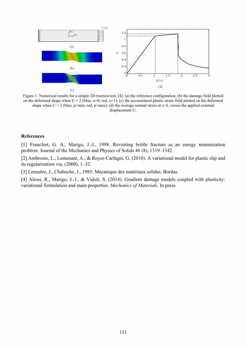
131
Figure 1: Numerical results for a simple 2D traction test, [4]: (a) the reference configuration; (b) the damage field plotted on the deformed shape when U = 2 (blue, α=0; red, α=1); (c) the accumulated plastic strain field plotted on the deformed
shape when U = 2 (blue, p=min; red, p=max); (d) the average normal stress at x=L versus the applied external displacement U.
References
[1] Francfort, G. A., Marigo, J.-J., 1998. Revisiting brittle fracture as an energy minimization problem. Journal of the Mechanics and Physics of Solids 46 (8), 1319–1342.
[2] Ambrosio, L., Lemenant, A., & Royer-Carfagni, G. (2010). A variational model for plastic slip and its regularization via, (2000), 1–32.
[3] Lemaitre, J., Chaboche, J., 1985. Mécanique des matériaux solides. Bordas.
[4] Alessi, R., Marigo, J.-J., & Vidoli, S. (2014). Gradient damage models coupled with plasticity: variational formulation and main properties. Mechanics of Materials. In press.

132
Geometric numerical integrators based on the magnus expansion in bifurcation problems for non-linear elastic solids
Anna Castellano1, Pilade Foti2*, Aguinaldo Fraddosio3, Salvatore Marzano4, and Mario Daniele Piccioni5
DICAR – Politecnico di Bari, Via Orabona 4, 70125 Bari, Italy [email protected], [email protected], [email protected], [email protected],
Keywords: nonlinear elasticity, bifurcation, geometric numerical integrators, Magnus expansion.
In the framework of three-dimensional non-linear elasticity, a number of “small on large” bifurcation problems lead to the analysis of a system of linear second order ODE’s with varying coefficients. It is a common practice trying to reduce the system of linear second order ODE’s to a simpler non-autonomous first order linear ODE system. Nevertheless, the resulting differential system may be somewhat complex and only numerically tractable; thus, it is crucial to adopt an adequate strategy for obtaining an accurate numerical solution for determining the singular value and the corresponding normalized bifurcation deformation field. For example, approximate expressions of the matricant of non-autonomous linear ODE systems, based either on the multiplicative integral of Volterra or on the truncated Peano expansion, have been recently proposed for bifurcation problems analyzed by means of the Stroh approach within the so-called sextic formalism (see [1], [2] and [3]).
Here, we discuss an alternative numerical method – based on the Magnus expansion (cf. [4]) – which furnishes an approximate exponential representations of the matricant of first order linear ODE systems. The Magnus expansion belongs to the so-called geometric numerical integrators, based on Lie-Group methods (see [5], [6] and [7] for appropriate references). To our knowledge, the applications of this method are not widespread in the continuum mechanics literature, but it has been shown in [8] that for problems involving singularities, bifurcations and wave propagation these methods may be useful and accurate. In particular, the Magnus expansion method may be very efficient in a number of applications on bifurcation analysis in continuum mechanics, since it features the determination of approximate solutions that preserve at any order of approximation the same qualitative properties of the exact (but unknown) solution; moreover, this method exhibits an improved accuracy with respect to other frequently used numerical schemes.
As an application of the Magnus method, here we study the possibility of toroidal twist-like bifurcations for an isotropic incompressible elastic tube subject to a primary pure circular shear. In this context, we recently investigated in [9] the possibility for a compressible Levinson-Burgess hollow cylinder subject to azimuthal shear to support axially periodic toroidal twist-like modes similar to the Taylor-Couette axially periodic cellular patterns observed when a viscous fluid confined between two differentially rotating concentric cylinders becomes unstable. We performed a numerical analysis based on the Magnus expansion of the underlying non-autonomous system of linear ODE, and conclude that severe state of shear may lead in solid bodies to periodic twist-like bifurcations of the Taylor-Couette form.
Here, we extend the bifurcation analysis developed in [9] to the case of incompressible isotropic elastic solids. We first show that for an arbitrary incompressible isotopic elastic material there exists an equilibrium axisymmetric circular shear deformation. Then, in order to investigate whether this primary deformation may bifurcate into an axially periodic toroidal twist-like mode, we study the incremental boundary-value problem by restricting our attention to a class of incremental displacements characterized by three unknown scalar functions of the radial coordinate and having axial periodic structure. This leads to a inhomogeneous system of three second order ODE’s, which we conveniently transform into a non-autonomous homogeneous system of six first order linear ODE’s with homogeneous boundary conditions. We then determine existence conditions for the

133
emergence of bifurcating periodic cell patterns and apply our general results to the case of an elastic tube modeled by an extended version of the Gent constitutive equation. The approximate matricant of the resulting explicit differential problem and the first singular value of the bifurcating load corresponding to a non-trivial twist-like solution are determined by employing a simplified version of the Magnus method, characterized by a truncation of the Magnus series after the second term.
References
[1] A. Goriely, R. Vandiver, M. Destrade. Nonlinear Euler buckling. Proc. R. Soc. A, 464: 3003-3019, 2008.
[2] A. L. Shuvalov. A sextic formalism for the three-dimensional elastodynamics of cylindrically anisotropic radially inhomogeneous materials. Proc. R. Soc. Lond., 459: 1611-1639, 2003.
[3] A. L. Shuvalov, O. Poncelet, M. Deschamps. General formalism for plane guided waves in transversely inhomogeneous anisotropic plates. Wave Motion, 40: 413-426, 2004.
[4] W. Magnus. On the exponential solution of differential equations for a linear operator. Comm. Pure Appl. Math., VII: 649-673, 1954.
[5] S. Blanes, F. Casas, J.A. Oteo, J. Ros. The Magnus expansion and some of its applications. Physics Reports, 470: 151-238, 2009.
[6] A. Iserles, H.Z. Munthe-Kaas, S.P. Norsett, A. Zanna. Lie-group methods. Acta Numer., 9: 215-365, 2000.
[7] A. Iserles, S.P. Norsett. On the solution of linear differential equations in Lie groups. Phil. Trans. R. Soc. A, 357: 983-1019, 1999.
[8] C. J. Budd, M.D. Piggott. The geometric integration of scale-invariant ordinary and partial differential equations. J. of Comput. and Appl. Mathematics, 128: 399-422, 2001.
[9] R. Fosdick, P. Foti, A. Fraddosio, S. Marzano, M. D. Piccioni. Taylor-like bifurcations for a compressible isotropic elastic tube. Mathematics and Mechanics of Solids, ISSN: 1081-2865, doi: 10.1177/1081286513496576, 2013.

134
Experimental and numerical approaches for the ultrasonic characterization of composite materials
Anna Castellano1, Pilade Foti2, Aguinaldo Fraddosio3, Salvatore Marzano4, and Mario Daniele Piccioni5
DICAR – Politecnico di Bari, Via Orabona 4, 70125 Bari, Italy [email protected], [email protected], [email protected], [email protected],
Keywords: Composite materials, Non-Destructive Testing, Ultrasonic Immersion Test, Anisotropic materials, Wave propagation.
The study of the mechanical behavior of non-traditional materials, such as composites and fiber-reinforced materials, biological and polymeric materials imposes to face challenging problems both at the theoretical and experimental level. In particular, an effective and emerging approach for the mechanical characterization of complex materials is offered by ultrasonic tests. Indeed, it has been observed that suitable measures of ultrasonic velocity waves allow for a enough detailed experimental identification of materials whose response is determined by a large number of moduli. For such applications, numerical simulations reveal very useful for a deeper understanding of the experimental measurements and for efficiently arranging the experimental set up.
In this paper, we propose an innovative experimental set up for immersion ultrasonic testing aimed at characterizing anisotropic materials. We focused our attention on unidirectional carbon fiber reinforced composites that we modelled as transversely isotropic elastic materials. A new experimental device together with an innovative software developed for managing the tests allow us to identify the elastic constants of the material by measuring ultrasonic velocities along according appropriate angles of incidence of the ultrasound beam. As a major result, we developed a multiphysics numerical model for simulating experimental phenomena related to the propagation of the ultrasonic beam like, for example, the reflection and the refraction of inclined beams at the interface between fluid and solid phases, which typically occur in immersion tests.
The results of the numerical analysis closely reproduce the experimental behavior in immersion ultrasonic tests and consequently may be considered as a good benchmark for designing future experiments involving much more complex materials characterized by higher degree of anisotropy.
References
[1] S. Siva Shashidhara Reddy, K. Balasubramaniam, C.V. Krishnamurthy, M. Shankar. Ultrasonic goniometry immersion techniques for the measurement of elastic moduli. Composite Structures, 67: 3–17, 2005.
[2] H. Seiner, M. Landa. Sensitivity analysis of an inverse procedure for determination of elastic coefficients for strong anisotropy. Ultrasonics, 43: 253–263, 2005.
[3] T. Kundu. Ultrasonic Nondestructive Evaluation: Engineering and Biological Material Characterization. CRC Press, 2004.
[4] A. Castellano, P. Foti, A. Fraddosio, S. Marzano, M.D. Piccioni, D. Scardigno. Simulation of an Ultrasonic Immersion Test for the Characterization of Anisotropic Materials. COMSOL Conference 2012, Milan, 2012.
[5] D. Royer, E. Dieulesaint. Elastic Waves in Solids I. Free and Guided Propagation. Springer, 1996.
[6] A. Castellano, P. Foti, A. Fraddosio, S. Marzano, M.D. Piccioni. Mechanical characterization of CFRP composites by ultrasonic immersion tests: experimental and numerical approaches. Submitted to Composites Part B, 2014.

135
[7] A. Castellano, P. Foti, A. Fraddosio, S. Marzano, M.D. Piccioni. Mechanical characterization of Apricena marble by ultrasonic immersion tests. SMART BUILT International Conference on Structural Monitoring of Artistic and Historical Building Testimonies, Bari, March 2014.
136
A micromechanical four-phase model to predict the compressive failure surface of cement concrete
Andrea Caporale1,a *, Raimondo Luciano1,b 1Department of Civil and Mechanical Engineering, University of Cassino and Southern Lazio, via
G. Di Biasio 43, 03043 Cassino (FR) Italy [email protected], [email protected]
* Corresponding author
Keywords: Cement concrete, micromechanics, compressive strength.
In this work, a micromechanical model is proposed in order to predict the failure surface of cement concrete subject to multi-axial compression. Cement concrete is one of most used materials in civil constructions. Different strengthening techniques have been introduced in order to increase the mechanical performances of cement concrete [1,2] and to strengthen existing structures made of concrete [3,4]. Beyond the structural behavior, attention must be paid to the behavior of plain concrete.
In a recent work [5], a four-phase micromechanical model has been proposed in order to simulate the non-linear instantaneous pre-peak response of cement concrete subjected to monotonically increasing loads; the concrete material is modeled as a composite with the following constituents: coarse aggregate (gravel), fine aggregate (sand) and cement paste. The cement paste contains some voids which grow during the loading process. In fact, the non-linear behavior of the concrete is attributed to the creation of cracks in the cement paste; the effect of the cracks is taken into account by introducing equivalent voids (inclusions with zero stiffness) in the cement paste. The three types of inclusions (namely gravel, sand and voids) have different scales, so that the overall behavior of the concrete is obtained by the composition of three different homogenizations; in the sense that the concrete is regarded as the homogenized material of the two-phase composite constituted by the gravel and the mortar; in turn, the mortar is the homogenized material of the two-phase composite constituted by the sand inclusions and a (porous) cement paste matrix; finally, the (porous) cement paste is the homogenized material of the two-phase composite constituted by voids and the pure paste; the pure paste is an ideal material that does not contain voids or other defects. The above mentioned three homogenizations are realized with the predictive scheme of Mori-Tanaka in conjunction with the Eshelby method, frequently used in the homogenization of composites [6,7]. The micromechanical method described in [5] provides the stress in the concrete material subject to a prescribed strain and, vice versa, the strain in concrete material subject to a prescribed stress. In the load case of prescribed uni-axial compression, the uni-axial stress can be plotted against the uni-axial strain so as to obtain the compressive stress-strain curve of concrete. Assuming that the compressive stress and strain are positive, the stress-strain curves provided by [5] in the load case of uni-axial compression exhibit a maximum compressive stress denoted by p , which represents the compressive strength c of
concrete. In [5], this micromechanical model has been used in order to capture peculiar aspects of the stress-strain curve in the load case of uni-axial compression:
in most concrete materials, a higher compressive strength is associated with a higher initial tangent Young’s modulus 0E ;
the formation and evolution of voids in the cement paste cause a reduction of the tangent line to the stress-strain curve;
a higher w c ratio of water to cement involves a concrete with a lower compressive strength c
and a lower tangent line 0E at the origin of the stress-strain curve;

137
the concrete materials having the same initial stiffness 0E also have the same p p ratio of peak
stress to peak strain, as predicted by phenomenological curves [8]; p is the strain corresponding
to p in the concrete stress-strain curve.
The same model used in [5] can also be used to determine the behavior of cement concrete in load cases of multi-axial compression. This is done in this work, where the failure surface of concrete subject to bi-axial or tri-axial compression is determined by using the model described in [5]. Next, the generic directions in the space of principal strains and principal stresses are denoted by the unit
vectors T
1 2 3ˆ ˆ ˆ n and T
1 2 3ˆ ˆ ˆ n , respectively. The proposed method determines the
vector ε of the principal strains in cement concrete subject to a prescribed stress σ n and, vice
versa, the vector σ of the principal stresses in cement concrete subject to a prescribed strain ε n ,
where is a positive parameter which increases during the loading process. In the load case of prescribed multi-axial compression, the stress σ can be plotted against the strain ε so as to
obtain a stress-strain curve; this curve exhibits a maximum stress p which represents the
strength in the load case of multi-axial compression defined by the vector σ n . The maximum
value of the loading parameter is p and the points p σ n define the failure surface of cement
concrete in multi-axial compression.
In the proposed model, the damage is smeared over the whole volume of concrete while in the post-peak behavior the damage localizes in limited zones. For this reason the proposed model, valid in the pre-peak range, results not suitable to capture the post-peak behavior. In this work, the pre-peak behavior provides essential information, such as the initial Young’s modulus of concrete and the compressive strength, which is the peak of the stress-strain curve of cement concrete. Specifically, the failure surfaces in the load cases of bi-axial and tri-axial compression are determined for different types of cement concrete and are compared with experimental failure surfaces.
References
[1] F. Bencardino, L. Rizzuti, G. Spadea, R.N. Swamy, Experimental evaluation of fiber reinforced concrete fracture properties, Composites Part B: Engineering 41 (2010) 17-24.
[2] R.S. Olivito, F.A. Zuccarello, An experimental study on the tensile strength of steel fiber reinforced concrete, Composites Part B: Engineering 41 (2010) 246-55.
[3] A. Aprile, A. Benedetti, Coupled flexural-shear design of R/C beams strengthened with FRP, Composites Part B: Engineering 35 (2004) 1-25.
[4] A. D’Ambrisi, L. Feo, F. Focacci, Experimental analysis on bond between PBO-FRCM strengthening materials and concrete, Composites Part B: Engineering 44 (2013) 524-32.
[5] A. Caporale, L. Feo, R. Luciano, Damage mechanics of cement concrete modeled as a four-phase composite, Composites: Part B (2014), In Press, http://dx.doi.org/10.1016/j.compositesb.2014.02.006
[6] C.C. Yang, R. Huang, A two-phase model for predicting the compressive strength of concrete, Cement and Concrete Research 26 (1996) 1567-77.
[7] C.C. Yang, R. Huang, Approximate strength of lightweight aggregate using micromechanics method, Advanced Cement Based Materials 7 (1998) 133-8.
[8] P. Desayi, S. Krishnan, Equation for the stress–strain curve of concrete, ACI J. 61 (1964) 345–50.

138
Multiscale analyses of a three layers osteochondral scaffold
G. Parisi2, S. Bignozzi3 ,E. Kon4, P. Vena2 1 Istituti Ortopedici Rizzoli, Via di Barbiano, 1/10 40136, [email protected]
2 Politecnico di Milano, Piazza Leonardo da Vinci, 32 20133 Milano, [email protected] 3 Istituti Ortopedici Rizzoli, Via di Barbiano, 1/10 40136, [email protected]
4 Istituti Ortopedici Rizzoli, Via di Barbiano, 1/10 40136, [email protected]
Keywords: Multiscale analyses, Analytical methods, Osteochondral tissue substitute.
Tissue engineering has great potential in providing the appropriate replacement of diseased articular cartilage with a compatible substitute able to grant a stable fixation into the joint defect and reliable integration with the subchondral bone1.
The replaced engineered tissue needs to be fully biocompatible with the individual subject and requires specific mechanical and structural properties for adequate functioning and integration within the articular joint. One of the most widely adopted strategies relies on the use of an artificial structure, also regarded as scaffolds, having the function of supporting stress under loading conditions and promoting the bio-mineralization process and the formation of new tissue.
The resulting tissue constructs generally exhibits an overall composition that resembles that of the original tissue, but the tissue structure at nano and micro scales may be considerably different from that of the native tissue. This difference may compromise proper functionality and integration of the implants2.
In this work an inhomogeneous monolithic scaffold is analyzed with 3 distinct phases, a chondral phase, an intermediate phase and a subchondral (bony) phase3. Each of the three layers is characterized by different constituents and architectural features in terms of average porosity. In particular, the chondral phase is the superficial layer composed by 100% deantigenated type I equine collagen. The intermediate layer (tide mark) and the bony layer instead, are formed by a randomly oriented network of collagen fibers with magnesium-enriched HA inclusions of different shapes (see table 1).
MATERIAL LAYER HA volumetric fraction ƒHA Collagen volumetric fraction ƒcol
Chondral 0 100
Intermediate 0.4 0.6
Subchondral 0.7 0.3 Table 1: material compositions for the three layer of the HA/Collagen osteochondral tissue substitute.
The mechanical properties of the multilayer scaffold is estimated by means of a multiscale hierarchical approach4 which spans from the collagen molecules level to the tissue level, including the effect of the bound water at the small length scale and the large porosity at the tissue scale5. In particular, a double porosity feature is accounted for, which allows for a large porous matrix with pores of the order of hundreds of microns in a solid phase which exhibits micron-size pores.
Furthermore, experimental mechanical characterization has been achieved by means of nanoindentation and micro-compression tests. Nanoindentation tests have been carried out using a flat punch with circular cross section having a 250 m radius; whereas, microcompression tests have been carried out using circular punches having up to 1 mm radius. Micro-compression tests have performed both in dry and liquid environment. For the tests run in liquid medium, a water/glycol solution has been used with the purpose to simulate the viscosity of blood (the typical working environment for the

139
scaffold). An good agreement has been obtained between the mechanical properties estimated in the experimental tests and the one predicted using the homogenization models.
The achieved results allowed to draw the relevant conclusion that the multiscale homogenization model has shown to be a reliable tool to estimate the mechanical properties of a multi-phase material like the osteochondral scaffold uder consideration.
References
[1] Swieszkowski W., Ho Saey Tuan B., Kurzydlowski K. J., Hutmacher D. W., Repair and regeneration of osteochondral defects in the articular joints, Biomolecular Engineering, Vol. 24 pp. 489-495, 2007.
[2] Kelly DJ, Prendergast PJ. Mechano-regulation of stem cell differentiation and tissue regeneration in osteochondral defects, J Biomech., Vol. 7, pp. 1413-22, 2005.
[3] Tampieri et al., Design of graded biomimetic osteochondral composite scaffolds, Biomaterials, Vol. 29, pp. 3539-46, 2008.C.
[4] Fritsch and C. Hellmich, ‘Universal’ microstructural patterns in cortical and trabecular, extracellular and extravascular bone materials: Micromechanics-base prediction of anisotropic elasticity. Journal of Theoretical Biology, Vol. 244, pp. 597-620, 2007.
[5] Hellimch, J-F Barthelemy, L. Dormieux, Mineal-collagen interactions in elasticity of bone ultrastructure- a continuum micromechanics approach. European Journal of Mechanics A/Solids, Vol. 23, pp. 783-810, 2004.
140
Damage propagation modeling of masonry structures subjected to dynamic loading
Jessica Toti1, a *, Vincenzo Gattulli1,b and Elio Sacco3,c 1 Department of Civil, Construction-Architectural and Environmental Engineering, University of
L'Aquila, Italy 2 Department of Civil and Mechanical Engineering, University of Cassino and Southern Lazio, Italy
[email protected], [email protected], [email protected]
Keywords: dynamic analysis, masonry, nonlocal damage, finite element method.
Cohesive structures, such as masonry or concrete structures constituting a large portion of existing building around the word. In the last forty years, an enormous growth in the development of numerical tools for structural analysis has been achieved. The development of dynamic inelastic analyses became an important tool for the evaluation of the safety level of the cohesive structures under earthquakes. The computational analysis of cohesive structures, subjected to dynamic or cyclic loadings, requires accurate stress-strain material models able to reproduce the real behavior of the structure. Research efforts on the cyclic response of cohesive material aim at providing an efficient model capable of predicting all the hysteretic characteristics of the material. Common models able to reproduce the cyclic are based on damage mechanics, plasticity theory and coupling of both.
Mathematical and numerical models of cohesive material failure must correctly reflect the energy dissipated in the fracture process zone. This is not the case if the stress-strain laws with softening is used within the standard continuum theory. Numerical results obtained with such models suffer from pathological sensitivity to the spatial discretization, e.g. to the size of finite elements. Upon mesh refinement, the energy dissipated by the numerical model decreases and tends to extremely low values, sometimes even to zero. As remedy, regularized models, based on nonlocal continuum approaches [6], can be adopted.
Indeed, the presence of damage or of other inelastic phenomena modifies the overall structural dynamic response; moreover, the damage propagation potentially interacts dynamically with the element vibrations. In particular, changes in its behavior are associated to the decay of the mechanical properties of the system [9]. Based on these considerations, many studies have been devoted to use the variations of the dynamic response for the detection of the structural damage. Particular attention has been focused on the use of frequencies only, on account of simplicity of measuring them and, therefore, their experimental reliability. In this framework, dynamic analyses of damaged structures have been performed in [5] with the aim to detect the damage state of the structure.
In the present work, a nonlocal damage-plastic model for dynamic finite element analyses of large scale masonry structures is proposed. The developed cohesive model is able to reproduce the main features characterizing the behavior of quasi-brittle materials under static or dynamic loadings, still remaining quite simple, i.e. governed by few parameters which can be determined by standard laboratory tests. In particular, the developed constitutive formulation is able to consider: the damaging evolution in tension and in compression, the plasticity in compression and the cyclic macroscopic behavior which accounts for the stiffness recovery due to the unilateral effect of the crack closure. The latter effect represents an important characteristic above all in the case of dynamic loadings. The proposed formulation is implemented as constitutive model for two-dimensional plane stress four node quadrilateral elements. The second order equations of motion are solved adopting implicit Newmark time integration scheme. The validation and the dynamic performance of the proposed model are demonstrated by numerical examples concerning the analysis of existing masonry structures (e.g. pillar, arch, vault).
References

141
[6] G. Pijaudier-Cabot, Z. Bažant, Nonlocal Damage Theory, J. Eng. Mech., 113 (1987), 1512-1533. [7] G. Borino, B. Failla, F. Parrinello, A symmetric nonlocal damage theory, Int. J. Solids Struct, 40 (2003), pp. 3621-3645. [8] J. Toti, S. Marfia, E. Sacco, Coupled body interface nonlocal damage model for FRP detachment, Comput. Method Appl. M., 260 (2013), pp. 1-23. [9] J. Toti, V. Gattulli, E. Sacco, Nonlocal damage propagation in the dynamics of masonry structures, submitted (2014). [10] U. Andreaus, P. Casini, F. Vestroni. Nonlinear dynamics of a cracked cantilever beam under harmonic excitation, Int. J. Nonlin. Mech., 42 (2007), pp. 566-575.

142
A micromechanical approach for the micropolar modeling of heterogeneous periodic media
Maria Laura De Bellis1, a *, Daniela Addessi1,b and Elio Sacco2,c 1 Dipartimento di Ingegneria Strutturale e Geotecnica, Università di Roma “Sapienza",
Via Eudossiana 18, 00184 Roma, Italy 2Dipartimento di Ingegneria Civile e Meccanica, Università di Cassino e del Lazio Meridionale
Via G. Di Biasio 43, 03043 Cassino, Italy [email protected], [email protected], [email protected]
Keywords: Heterogeneous materials, Homogenization, Cosserat continuum, Periodicity, Constitutive identication.
Composite materials, both natural or manufactured, are widely used in many fields of engineering and for different types of structures. Although they may have very distinct features, they are all characterized by a heterogeneous micro-structure. The study of the constitutive response of such materials is essential both to reproduce the behavior of existing structures and to design innovative ones with optimized properties.
Various approaches, characterized by different formulations, have been proposed in literature to deal with this issue; among others the homogenization techniques have been widely used. In particular, these techniques analyze the actual heterogeneous material at two different scales: the macro-scale, where an effective homogenized medium is considered, characterized by overall mechanical properties, which are estimated from detailed information available at a lower scale, the micro-scale, where the texture, the geometry and the constitutive laws of the constituents are accurately described.
This work is a contribution towards the study of the homogenized response of periodic composite materials, considering a Cosserat continuum at the macro-level and a Cauchy continuum at the micro-level. The computational homogenization technique, here adopted, has proved to be very effective to predict the macroscopic behavior of composite materials[1]. In particular, thanks to the adoption of a generalized continuum at the macro-level it is possible to naturally account for length-scale parameters that play a fundamental role when high strain and stress gradients at the macro-level occur, or when the microscopic length of the constituents is comparable to the wavelength of variation of the strain and stress mean fields at the macro-level[2].
In this paper, because of the assumed regular texture of the analyzed composite material, a Unit Cell (UC) is selected at the micro-level and, consistently with the strain-driven approach, the two levels are linked through a kinematic map based on a third order polynomial expansion [3].
Firstly, the problem of determining the displacement perturbation fields is investigated. To this end, a new micromechanical approach, based on the decomposition of the perturbation fields in terms of functions which depend on the macroscopic strain components [4,5], is proposed. A consistently defined Boundary Value Problem is solved and the results obtained by analyzing a single UC are in a very good agreement with the reference solution evaluated on a large RVE made from the same material.
Then, the identification of the homogenized linear elastic 2D Cosserat constitutive parameters is performed, by using the Hill-Mandel technique, based on the generalized macrohomogeneity condition. The influence of the selection of the UC is analyzed and some critical issues are outlined. By analyzing two different UCs, selected for representing the composite texture, it emerges that the constitutive response of the homogenized medium depends on the choice of the cell. In fact, while the elastic Cauchy coefficients are independent on the specific choice of the UC, for the bending and skew-symmetric shear Cosserat coefficients this does not occur, at least in the framework of computational homogenization. This fact is also confirmed by the results obtained from the structural

143
application. It is also highlighted that considering a RVE made from an assemblage of UCs, the elastic coefficients converge to the same value, apart from the considered UC. This value corresponds to that evaluated by simply considering at the micro-level a homogenized Cauchy medium.
References
[1] De Bellis, M., Addessi, D., A Cosserat based multi-scale model for masonry structures. Int J Multiscale Com 9 (5), (2011)543-563.
[2] Forest, S., Trinh, D., Generalized continua and non-homogeneous boundary conditions in homogenisation methods. ZAMM-Z Angew Math Me 91 (2) (2011) 90-109.
[3] Addessi, D., De Bellis, M. L., Sacco, E., Micromechanical analysis of heterogeneous materials subjected to overall Cosserat strains. Mech Res Commun 54 (2013) 27-34.
[4] Yuan, X., Tomita, Y., Andou, T., A micromechanical approach of nonlocal modeling for media with periodic microstructures. Mech Res Commun 35 (1-2), (2008) 126 -133.
[5] Bacigalupo, A., Gambarotta, L., Second-order computational homogenization of heterogeneous materials with periodic microstructure. ZAMM-Z Angew Math Me 90 (11)( 2011) 796-811.

144
An experimental investigation on the axial and rotational behavior of web-flange junctions of open-web pultruded glass fibre-reinforced
profiles
Luciano Feo1,a*, Ayman S. Mosallam2,b and Rosa Penna1,c 1Department of Civil Engineering, University of Salerno, Italy
2Department of Civil & Env. Engineering, University of California Irvine, USA [email protected], [email protected], [email protected]
* corresponding author
Keywords: Pultruded Composites, Web-Flange Junction, Mechanical Testing
Fibre-reinforced polymer (FRP) composites represent a class of advanced materials whose use has spread from the aeronautical, mechanical and naval industry to civil infrastructure due to their high strength-to-weight ratio, low maintenance cost and high corrosion resistance.
The majority of the commercially-produced pultruded fibre-reinforced polymers (PFRP) have been designed and developed by the pultrusion industry and are intended for low-stress applications.
Recently, composites have been introduced as primary structural members to replace or complement other conventional materials, such as steel, concrete and wood, in critical applications such as bridge decks, pedestrian bridges, and recently in highway bridges and other infrastructural systems.
As the interest in using PFRP profiles in construction applications continues to increase, it became critical and essential to understand their short- and long-term mechanical behavior. Several recent and relevant studies [1-10] have been conducted and focused on the performance of PFRP frame structures. The results of these studies have highlighted the major problems associated with the structural deficiency of unidirectional PFRP profiles, especially at the web-flange junctions (WFJ) that lack fibre continuity. This lack of fibre continuity may lead to progressive degradation in both axial and rotational stiffnesses and strength of these junctions, affecting both the buckling, post-buckling and the overall short- and long-term structural integrity of the PFRP profiles.
Moreover, these studies have highlighted the influence of the architecture of the web-flange junctions on the collapse of the profiles. In fact, the mechanical properties of the WFJ are not the same as those of the flats parts of the web and the flanges due to them also depending on the specific processing method used by the manufacturer to produce PFRP profiles.
This work has been developed within the research activities of a multi-phase comprehensive joint research program between University of Salerno, Italy, and the University of California, Irvine, USA, on investigating one of the major structural issues that defines the strength limit-state of pultruded fibre-reinforced polymer profiles. In particular, both the axial and rotational stiffness of WFJ of I-, H- and L- profiles have been investigated through in-depth experimental program in order to develop P-δ and M-θ relations that are necessary for accurate analytical predictions of both the local and global responses of PFRP frame structures. In fact, their failure mechanism has yet to be fully understood and they often involve failure of the web-flange junctions. Moreover, P-δ and M-θ relations are also essential for establishing optimum and reliable design limit-states of such structures.
Specifically, the research program has been divided into the following two phases:
- the first phase consisted of an experimental investigation carried out at the Materials and Structural Testing Laboratory (LMS) of the Department of Civil Engineering (DICIV) of the University of Salerno in order to evaluate the axial strength and stiffness of WFJ of PFRP I-profiles;
- the second phase was an experimental study conducted at the Structural Engineering Testing Hall (SETH) of the University of California Irvine (UCI) to evaluate both the axial and the rotational strength and stiffnesses of WFJ of PFRP H- and L-profiles.

145
The results gathered from this multi-phase research program provided important information on one of the major structural deficiencies and limitations related to the inherent weakness of the web/flange junctions of the majority of commercially produced, off-the-shelf unidirectional pultruded composites.
It is hoped that the results obtained from this research will fill exisiting gaps and provide structural engineers with essentail engineering data to assist to secure optimum designs and obtain the maximum benefit of PFRP materials.
References
[1] Mosallam A.S., Elsadek A.A., Pul S. Semi-rigid behavior of web-flange junctions of open-web pultruded composites in Proceeding of the International Conference on FRP Composites, San Francisco, California (2009). [2] Mosallam A.S., Bank L.C. Short-term behavior of pultruded fiber reinforced plastic frame. Journal of Structural Engineering (ASCE), 118(7), pp. 1037–1954 (1992). [3] Mosallam A.S., Abdelhamid M.K. Dynamic behavior of PFRP structural Sections, in Proc. of ASME (Energy Sources Tech. Conf. and Expo, Composite Material Tech.), 53, pp. 37–44 (1993). [4] Davalos J.F., Salim H.A., Qiao P., Lopez-Andio R. Analysis and design of pultruded FRP shapes under bending. Composites Part B: Engineering, 27B(3,4), pp. 295–305 (1996). [5] Mosallam A.S., Abdelhamid M.K., Conway J.H. Performance of pultruded FRP connection under static and dynamic loads. Journal of Reinforced Plastic and Composites, 13, pp. 1052–1067 (1996). [6] Liu X., Mosallam A.S., Kreiner J. A numerical investigation on static behavior of pultruded composite (PFRP) portal frame structures in Proceeding of the 43rd International SAMPE Symposium and Exhibition, Anaheim, California (1998). [7] Mosallam A.S. Durability of pultruded fiber reinforced polymer (PFRP) composites in mining environments in Durability of fiber reinforced polymer (FRP) composites for construction, Edited by B. Benmokrane and H. Rahman, pp. 649-659 (1998). [8] Turvey G.J., Zhang Y. Characterization of the rotational stiffness and strength of web-flange junctions of pultruded GRP WF-sections via web bending tests. Composites Part A: applied science and manufacturing, 37, pp. 152–164 (2006). [9] Turvey G.J, Zhang Y. Shear failure strength of web-flange junctions in pultruded GRP WF profiles. Construction and Building Materials, 20, pp. 81–89 (2006). [10] Feo L., Mosallam A. S., Penna R., Mechanical behavior of web-flange junctions of thin walled pultruded I-profiles: An experimental and numerical evaluation. Composites Part B: Engineering, 48, pp.18-39 (2013).

146
Development of biodegradable magnesium alloy stents with coating: the peeling problem
Lorenza Petrini1,a *,Wei Wu2,b, Lina Altomare2,c, Barbara Previtali3,d, Maurizio Vedani3,e
and Francesco Migliavacca2,f 1Civil and Environmental Engineering Department, Politecnico di Milano, Italy
2Laboratory of Biological Structure Mechanics, Chemistry, Materials and Chemical Engineering ‘Giulio Natta’ Department, Politecnico di Milano, Italy
3Mechanical Engineering Department, Politecnico di Milano, Italy [email protected], [email protected], [email protected], [email protected],
[email protected], [email protected]
Keywords: coated stents, corrosion, biodegradable materials, coating adhesion.
Biodegradable stents are attracting the attention of many researchers in biomedical and materials research fields since they can absolve their specific function for the expected period of time and then gradually disappear [1]. This feature allows avoiding the risk of long-term complications such as restenosis or mechanical instability of the device when the vessel grows in size in peadiatric patients. Up to now biodegradable stents made of polymers or magnesium alloys have been proposed. However, both the solutions have limitations. The polymers have low mechanical properties, which lead to devices that cannot withstand the natural contraction of the blood vessel: the restenosis appears just after the implant, and can be ascribed to the compliance of the stent. The magnesium alloys have a level of toxicity similar to the one of the polymers and much higher mechanical properties. Unfortunately, they dissolve too fast in the human body: the duration in a blood vessel is about 2-3 months and not 8-10, as should be to withstand the vessel remodeling.
In this work we present some results of an ongoing study aiming to the development of biodegradable stents made of a magnesium alloy that is coated with a polymer having a high corrosion resistance. The mechanical action on the blood vessel is given by the magnesium stent for the desired period, being the stent protected against fast corrosion by the coating. The coating will dissolve in a longer term, thus delaying the exposition of the magnesium stent to the corrosive environment. Our study required the following steps: i) selection of a Mg alloy suitable for stent production, having sufficient strength and elongation capability; ii) optimization of the alloy microstructure through equal channel angular pressing; iii) optimization of the stent geometry to minimize stress and strain after stent deployment and improve scaffolding ability; iii) selection of a coating able to assure enough corrosion resistance and to avoid detachment from substrate during stent expansion; iv) set up of the procedure to produce magnesium stent, in terms of laser cut and surface finishing.
In the following the study performed on the adhesion ability of the selected coating (poly-caprolactone, PCL, Mn = 80 000 g/mol, Sigma-Aldrich, product number 440744-250G)) is described. Previous studies found that peeling phenomenon (or coating delamination) sometimes happens for coated stainless stents during stent expansion [2]. If this happens to coated magnesium stents (MAS), it will lead to a worse result than the uncoated MAS: indeed, the corrosion will concentrate at the unprotected location and the attack up will accelerate the rupture of the structure. Furthermore, the peeling of coated MAS during expansion should be strictly avoided. Finite element analysis (FEA) is a good method to study the peeling problem of MAS. Until now, only one work has used FEA to study coating delamination of stainless steel by means of the cohesive zone method (CZM)[3]. Herein, CZM implemented in the commercial code ABAQUS (Dassault Systèmes, Simulia Corp., USA) is applied to study our problem. Experimental tests were performed to find the cohesive element parameters. PCL was dissolved in chloroform at a concentration of 5% w/v and was dropped onto AZ31 foils (70mm x 4mm x0.8mm). Samples were left under a hood for 24 hours to allow the complete solvent evaporation and a uniform PCL coating with a thickness of 0.1 mm was obtained. A

147
90-degree peeling test (Figure 1 left) was carried out on a MTS Synergie 200H testing machine (MTS Systems Corporation, Minneapolis, MN,USA). Three samples were tested. The experimental tests were reproduced numerically by FEA (Figure1 right).. In particular the 2D stent strut model with a polymer coating is extracted from the 3D stent model (Figure2 left). Only one side of the coating was studied because of the symmetry of the location. A symmetrical boundary condition in Y-direction was applied to one strut end and a displacement in Y-direction was applied to the other end to simulate thestent expansion to a final diameter of 3 mm. After expansion, the cohesive elements were stretched and the coating had different separation ranges according to the location; however, none of them has reached the maximum traction stress thus the damage did not affect the cohesive elements and the scalar damage variable D was consequently 0 (Figure 2 right). The simulation suggests that under the studied conditions the peeling should not occur to the coating of the investigated stent design. Experimental tests are under investigation to support the model findings.
Figure 1: Experimental (left) and numerical (right) peeling test on AZ31 foil coated by PCL.
Figure 2: FEA 2D model of a coated stent strut (left) and final configuration after stent expansion with results in terms of
damage parameter in the coating (right).
References
[1] Y. Onuma, J. Ormiston and P.W. Serruys, Bioresorbable Scaffold Technologies, Circ. J.75 (2011) 509-20.
[2] W M.W.Z. Basalus, K. Tandjung, T. van Westen, H. Sen, P.K.N. van der Jagt, D.W. Grijpma, A.A. van Apeldoorn, and C. von Birgelen, Scanning Electron Microscopic Assessment of Coating Irregularities and their Precursors in Unexpanded Durable Polymer-Based Drug-Eluting Stents. Catheter. Cardio. Inter. 79 (2012) 644-53.
[3] C.G. Hopkins, P.E. McHugh and J.P.McGarry, Computational Investigation of the Delamination of Polymer Coatings During Stent Deployment, Ann Biomed Eng;38 (2010) 2263-73.

148
Interface constitutive relation derived from a representative adhesive layer
Guido Borino1, a * and Francesco Parrinello1,b
1Università di Palermo, Dipartimento di Ingegneria Civile, Ambientale, Aerospaziale, dei Materiali, Viale delle Scienze Ed.8, 90128 Palermo, Italy
[email protected], [email protected]
Keywords: Interface model, Cohesive-frictional, Multiscale analysis.
The mechanical description of joined structural elements made of different materials is typically carried out by inserting a mechanical interface in between the two clamped bulk components. The mathematical joining surface is then the locus demanded to represent all the main mechanical processes which develops along the joining zone.
Actually, along the joining zone, which is a relative thin layer, several complex nonlinear mechanical process may develop, such as, damage localization, decohesion phenomena, fracture initiation and propagation etc. The main difficulties are promoted by the fact that, beside the different mechanical properties of the two materials joined, the interface possesses specific properties in itself. The usual adopted approach introduces a phenomenological zero thickness interface with very simple characterizing properties, namely, assigning only the fracture energy constant is often enough in order to drive a fracture propagation analysis [1, 2]. The increasing demand of more accurate description of the complex interactions which emerges along these joining zones has produced more sophisticated phenomenological interface models, which, in turn can deals with aspects such as cyclic loading-unloading, cohesive-frictional transition, damage and plasticity phenomena, dilatancy and so on [3,5]. On the other hand, in the last years a new mechanical approach is emerging as alternative at a pure phenomenological description. In this new approaches, the actual constitutive relations are indirectly derived analyzing the material as an heterogeneous substructure and evaluating its mechanical response at its own micro scale. This general structural analysis is named multi-scale mechanical approach and has given a significant improvement in understanding the material nonlinear constitutive behavior starting from micro mechanical response and the relevant nonlinear homogenization procedure. More than this, multiscale approaches have been proved to be valuable tools for material design and for optimization of mechanical response performances.
In the present contribution a two scale approach is presented in which the concept of Representative Adhesive Layer is introduced. The Representative Adhesive Layer is a thin layer of finite thickness in which the adhesion surface is a rough surface with its own morphology, and also specific microstructure adhesive features can be introduced at this scale. The idea of performing a structural analysis with interface, adopting a multiscale approach for interface is already present in the recent literature [6,7].
In the present formulation the analysis is performed over a microscale layer element of small length, which is considered to reproduce a perfect periodic ligament. The investigation is then confined to the mechanical response of this Representative Adhesive Layer employing proper periodic boundary conditions at the two ends of the element, and deriving the relation between macro tractions and macro displacement jumps by means of specific homogenization techniques and then employed for the analysis at structural level.
References
[1] A. Needleman, An analysis of tensile decohesion along an interface, J. Mech. Phy. Sol. 38 (1990) 289–324.

149
[2] O. Allix, P. Ladevèze, A. Corigliano, Damage analysis of interlaminar fracture specimens, Comp. Struct., 31 (1995), 61–74.
[3] G. Alfano, E. Sacco, Combining interface damage and friction in a cohesive-zone model Int. J. Num. Meth. Eng., 68 (2006) 542-582
[4] F. Parrinello, B. Failla, G. Borino, Cohesive–frictional interface constitutive model, Int. J. Sol. Struct. 46 (2009) 2680–2692.
[5] A. Spada, G. Giambanco, P. Rizzo, Damage and plasticity at the interfaces in composite materials and structures, Comp. Meth. Appl. Mech. Engng. 198 (2009) 3884 – 3901.
[6] K. Matouš, M. G. Kulkarni, P. H. Geubelle, Multiscale cohesive failure modeling of heterogeneous adhesives, J. Mech. Phy. Sol. 56 (2008) 1511–1533
[7] C. B. Hirschberger, S. Ricker, P. Steinmann, N. Sukumar, Computational multiscale modelling of heterogeneous material layers, Eng. Fract. Mech. 76 (2009) 793–812

150
A cohesive-zone model simulating damage, friction and interlocking
Roberto Serpieri1,a*, Elio Sacco2,b and Giulio Alfano3,c 1 Università degli Studi del Sannio, Dipartimento di Ingegneria,
Piazza Roma n. 21 - 82100, Benevento, Italy 2 Università di Cassino e del Lazio Meridionale, Dipartimento di Ingegneria Civile e Meccanica,
Via di Biasio n. 43 - 03043 Cassino (FR), Italy 3 Brunel University, School of Engineering and Design, Uxbridge, UB8 3PH, UK
[email protected], [email protected], [email protected]
Keywords: Interface Friction, Thermodynamics with Internal Variables, Interlocking, Interface Elements, Fracture Energy.
Cohesive-zone models (CZMs) are widely used to simulate initiation and propagation of cracks along structural interfaces. They represent an effective alternative approach to fracture-mechanics-based methods for a wide variety of problems at very different scales, such as crack growth in dams, mortar-joint failure in brick masonry, bond-slip response of reinforcing bars in concrete, debonding of adhesive joints, delamination or fibre-matrix debonding in composites, among many others. Many of such problems entail combination of de-cohesion and frictional sliding, which is often accompanied by dilatancy, in turn associated with the interlocking effect created by the asperities of the fracture surface. Therefore, in order to formulate models that properly account for the underlying physics of the problem it is essential to capture the distinct types of dissipation due to fracture and friction, the influence of the geometry of the asperities on the interlocking effect.
Several interface models accounting for damage-friction coupling have been proposed in literature, see e.g. Del Piero and Raous [1] and references therein. Some of them are based on nonassociative softening plasticity, as for the multi-dissipative interface model proposed by Cocchetti et al. [2] and the contributions given by Bolzon and Cocchetti [3] and by Červenka et al. [4] in the field of concrete dams analysis, and by Giambanco et al. [5].
A different strategy was followed by Alfano and Sacco [6], Alfano et al. [7] and, more recently, Sacco and Toti [8], where interface damage and friction have been combined in a cohesive zone model based on a simplified micromechanical formulation. The main idea was to consider a representative area at a micromechanical scale, which is assumed to be additively decomposed into an undamaged and a fully damaged part; moreover, it is supposed that friction occurs only on the latter. The evolution of damage is assumed to depend on the elastic energy in the undamaged part while the frictional behaviour is governed by a Coulomb law. To simulate dilatancy and interlocking this approach was adopted by Serpieri and Alfano [9], within a multi-scale framework in which, at a small scale, the asperities of the interface are represented in the form of a periodic arrangement of distinct inclined planes, denominated Representative Interface Element (RIE). On each of these planes the interaction is governed by the formulation proposed in Alfano and Sacco (2006).
The above formulation by Serpieri and Alfano was recently revisited by Serpieri et al. [10], where it was shown that use of a single damage variable, combined with the choice of having a threshold damage function only depending on the damage variable itself and an equivalent displacement norm, requires coincidence of fracture energies in modes I and II to preserve thermodynamic consistency. Furthermore, it was shown that the enhancement of the model to account for friction and interlocking, based on the formulation proposed by Serpieri and Alfano [9], results in retrieving the experimental evidence that that the measured fracture energy in mode II is typically quite higher than in mode I, and more generally, that for mixed-mode cases with positive (opening) mode I, the measured fracture energy increases with the mode II-to-mode I ratio. Both facts are well supported by good agreement between experimental and numerical results.

151
Open issues concerning the approach presented in Refs. [9, 10] are related to the extension of the kinematics of the RIE-based multi-scale framework to account for relative displacements that are large compared to the characteristic size of the interface asperities.
Further relevant issues concern the extensibility of the multi-plane description to account for the non-linear behaviour of the asperities at the micro- or meso-scale under cyclic loading. In particular, the asperity-related non-linear behavior can involve plasticity, damage, crushing and wear effects which play, to different extents, a significant role in decohesion of rock interfaces [11] and rebar-to-concrete bond-slip [12]. More generally the interaction between damage evolution and crack growth on the interface with other dissipative processes in the bulk material adjacent to the interface is an area worth of further investigation. Methods to account for fibre bridging could also be a possible enrichment of the model for the simulation of delamination in fibre-reinforced composites [13].
In this contribution the above formulations [6-10] will be reviewed and more recent developments made to extend the RIE approach in order to address the above highlighted issues will be presented.
References
[1] G. Del Piero and M. Raous, A unified model for adhesive interfaces with damage, viscosity and friction. Eur J. Mech. A/Solids. Vol. B, 29(4) (2010) 496-507.
[2] G. Cocchetti, G. Maier and X.P. Shen, Piecewise linear models for interfaces and mixed mode cohesive cracks. Comp Model. Eng. Sci. 3 (2002) 279–298.
[3] G. Bolzon, G. Cocchetti, Direct assessment of structural resistance against pressurized fracture. Int. J. Num. Anal. Meth. Geomech. 27(2003) 353–378.
[4] J. Červenka, J.M. Chandra Kishen, V.E. Saouma, Mixed mode fracture of cementitious bimaterial interfaces; part II: numerical simulation. Eng. Frac. Mech. 60 (1998) 95–107.
[5] G. Giambanco, S. Rizzo, R.. Spallino, Numerical analysis of masonry structures via interface models. Comp. Meth. Appl. Mech. Eng., 190 (2001) 6493–6511.
[6] G. Alfano and E. Sacco, Combining interface damage and friction in a cohesive-zone model. Int. J. Num. Meth. Eng. 68 (2006) 542-582.
[7] G. Alfano, S. Marfia, E. Sacco, A cohesive damage-friction interface model accounting for water pressure on crack propagation. Comp. Meth. Appl. Mech. Eng. 196 (2006) 192-209.
[8] E. Sacco, and J. Toti, Interface elements for the analysis of masonry structures. Int. J. Comp. Meth. Eng. Sci. Mech. 11 (2010) 354-373.
[9] R. Serpieri, G. Alfano, Bond-slip analysis via a thermodynamically consistent interface model combining interlocking, damage and friction, Int. J. Num. Meth. Eng. 85 (2011) 164-186.
[10] R. Serpieri, E. Sacco, G. Alfano, A thermodinamically consistent derivation of a frictional-damage cohesive-zone model with different mode I and mode II fracture energies. submitted to Eur J. Mech. A/Solids. (2014).
[11] H.S. Lee, Y.J. Park, T.F. Cho, K.H. You, Influence of asperity degradation on the mechanical behavior of rough rock joints under cyclic shear loading. Int. J. Rock Mech. Min. Sci., 38(7) (2001) 967-980.
[12] H. Shima, L.L. Chou, H. Okamura, Bond Characteristics in post-yield range of deformed bars. Concrete Library of JSCE 10 (1987) 113-124.
[13] B.F. Sørensen, T. K. Jacobsen. Characterizing delamination of fibre composites by mixed mode cohesive laws. Comp. Sci. Techn. 69(3) (2009) 445-456.

152
Crack detection in beam-like structures by nonlinear harmonic identification
Paolo Casini1, a *, Oliviero Giannini2,b and Fabrizio Vestroni1,c 1Dipartimento di Ingegneria Strutturale e Geotecnica, Università degli Studi di Roma “la Sapienza”
Via Eudossiana, 18 00184, Roma, Italy 2Università degli Studi Niccolò Cusano Via Don Carlo Gnocchi, 3 00166, Roma, Italy
[email protected], [email protected], [email protected]
Keywords: Fatigue crack; damage identification; nonlinear dynamics; cracked beam model
The occurrence of cracks in civil or mechanical systems leads to dangerous effects for the structural integrity and causes anomalous behaviors. In order not to compromise the safety, the detection of a crack in the early stage is of great interest. The presence of a crack not only causes a local variation in the mechanical characteristics of the structure at its location, but it also has a global effect involving the entire structure. For this reason, the dynamic characterization of cracked structures can be used for damage detection in non-destructive tests and, among the various techniques, vibration-based methods provide an effective means of detecting fatigue cracks in structures [1].
There are two main categories of crack models used in vibration-based detection methods: open crack and breathing crack models. In the first case it is assumed that the crack in a structural member remains open during vibration. This assumption is usually satisfied in notched beams and when the damage is rather large; this model avoids the complexity resulting from nonlinear behavior when a breathing crack is presented. On the contrary, breathing behavior is generally reported in the case of fatigue cracks, also when the damage affects only a small portion of the cross section of the structural element; it requires a nonlinear model to take into account its effect on the system dynamics; in fact the breathing crack model considers that, during the vibration cycle of a structure, the edges of the crack come into and out of contact, leading to sudden changes in the dynamic response of the structure. Depending on the crack model, vibration based methods are also classified into two categories: the linear and the nonlinear approaches. The first group of methods can identify only the open cracks at an advanced stage, once changes in modal parameters become significant [2]. For this reason, refined studies focus on the nonlinear response characteristics that can be investigated to identify the presence of the crack in an early stage. In fact, the structures with breathing cracks behave similarly to bilinear systems and hence exhibit nonlinear phenomena in the dynamic response even for low damage. Therefore in the second group of methods, the identification is obtained by assuming as damage indicators some peculiar characteristics of the nonlinear dynamic response such as the presence of sub and super harmonics, the changes in the phase diagrams, the rise of superabundant nonlinear normal modes and bifurcations [3-5].
The dynamic behavior of beam-like structures with fatigue cracks forced by harmonic excitation is characterized by the appearance of sub and super-harmonics in the response even in presence of cracks with small depth. Since the amplitude of these harmonics depends on the position and the depth of the crack, an identification technique based on such a dependency has been developed by the authors in [5]. The main advantage of this method relies on the use of different modes of the structure, each sensitive to the damage position in its peculiar way.
In this study the identification method proposed in [5] is extended and detailed through numerical examples tested on structures of increasing complexity to evaluate the applicability of the method to engineering applications. The amount of data to obtain a unique solution and the optimal choice of the observed quantities are discussed. Finally, a robustness analysis is carried out for each test case to assess the influence of measuring noise on the damage identification; the robustness of the identification, evaluated through a Monte Carlo simulation, is shown to be quite strong to both

153
measuring and modeling errors envisioning the possibility for in-field applications of this method even in the case of very small cracks.
References
[1] A. Morassi and F. Vestroni, Dynamic methods for damage detection in structures, Springer-Verlag, ISBN: 3211787763, 2008.
[2] A. Morassi, Crack-induced changes in eigenparameters of beam structures, Journal of Engineering Mechanics, 119(9) (1993) 1798-1803
[3] U. Andreaus, P. Casini, F. Vestroni, Nonlinear dynamics of a cracked cantilever beam under harmonic excitation, International Journal of Non-linear Mechanics 42 (3) (2007) 566-575.
[4] P. Casini, O. Giannini, F. Vestroni, Persistent and ghost Nonlinear Normal Modes on the forced response of non-smooth systems, Physica D 241 (2012) 2058–2067.
[5] O. Giannini, P. Casini and F. Vestroni, Nonlinear harmonic identification of breathing cracks in beams, Computer and Structures, 129 (2013) 166-177.

154
A data fusion based approach for damage detection in linear systems
Ernesto Grande1, a and Maura Imbimbo2,b* 1Dept. of Civil and Mechanical Engineering, University of Cassino and Southern Lazio,
Via G. Di Biasio 43, 03043 Cassino, Italy [email protected], [email protected]
Keywords: damage identification; modal strain energy; data-fusion.
One of the main goal of dynamic identification is to derive information about the health of systems by monitoring changes affecting their dynamic properties due to the presence of damage. Indeed, considering damage indicators just based on modal parameters of systems before and after the damage, three possible levels of information can be derived: presence of damage (level 1), position of damage (level 2), severity of damage (level 3). In this context modal strain energy (MSE) is often used as basis for defining a damage detection index for systems based on the change of its dynamic properties and elemental stiffness of systems. The studies available in literature, among which [1-4], show the ability of this indicator to cover all the levels of information concerning the status of damaging of systems. Nevertheless, the same studies have also underlined some drawbacks of this approach, which generally arise when multiple damages occur or significant levels of noise/error affect the identified dynamic properties of systems. In these cases the major difficulties depend on identifying only a limited number of modes and not always those more sensible to the damage scenarios.
It is, thus, important to improve the performance of the traditional MSE based damage indicator in the case of multi damage locations, noise-polluted data and reduced number of modes.
Recently, in order to improve the ability of classical indicators to detect damage of systems, some literature studies [5-9] propose to extent the classical data information fusion techniques [10] to structural damage identification with the intent of combining information from different sources and improving the final result.
In this context, this paper presents an approach for damage identification of systems, which combines the use of damage indicators derived through the MSE with a multi stage data-fusion procedure. Specifically, considering different sets of the identified modes of vibration as information sources, modal strain energy change ratios are evaluated and converted in local decisions. The single decisions provided by each source constitute the data sent to the fusion center, where they are combined on the basis of a fusion approach that provides the global decision. More specifically, the methodology followed in the present paper is based on the classical Dempster-Shafer (DS) theory of evidence.
The approach is applied to some numerical examples with different damage scenarios, set of identified modes of vibrations and, also, noise levels. The obtained results clearly show that the proposed approach can improve the performances of the classical MSE based damage indicator in the case of single damage scenarios and, mainly, in the case of multiple damage scenarios where generally the classical indicators fail. The results show also a significant robustness of the approach in presence of noises. In all these cases the proposed approach provides efficient information in terms of location and also extent of damage.
References
[1] Doebling S., Hemez F., Peterson L., Farath C., (1997). Improved damage location accuracy using strain energy based on mode selection criteria. AIAA Journal; 35(4), 693-699.
[2] Shi Z., Law S., Zhang L., (1998). Structural damage localization from modal strain energy change.
155
Journal of Sound and Vibration; 218(5), 825-844.
[3] Shi Z., Law S., Zhang L., (2002). Structural damage detection from elemental modal strain energy change. Journal of Engineering Mechanics; 128(5), 521-529.
[4] Ren W., Roeck G., (2002). Discussion of "Structural damage detection from elemental modal strain energy change, by Shi, Z., Law, S.S., Zhang, L.M.". Journal of Engineering Mechanics; 128(3), 376-377.
[5] Fei Q., Li A., Han X., (2009). Simulation study on damage localization of a beam using evidence theory. Procedia Engineering; 1, 147-150.
[6] Guo H., Li Z., (2009). A two-stage method to identify structural damage sites and extents by using evidence theory and micro-search genetic algorithm. Mechanical Systems and Signal Processing; 23, 769-782.
[7] Bao, Y. Q., Li, H., An, Y. and Ou, J. P., (2011), Dempster-Shafer evidence theory approach to structural damage detection, Structural Health Monitoring, 10 (3), 235-246.
[8] Bao, Y. Q., Xia, Y., Li, H., Xu, Y. L. and Zhang, P., (2012), Data fusion-based structural damage detection under varying temperature conditions, International Journal of Structural Stability and Dynamics, 12 (6), No. 1250052.
[9] Grande E. and Imbimbo M., (2014), A multi-stage data-fusion procedure for damage detection of linear systems based on modal strain energy, Journal of Civil Structural Health Monitoring, 4(2), 107-118.
[10] Shafer G., (1976). A mathematical theory of evidence. Princeton, NJ: Princeton University Press.

156
Superelastic and Shape Memory effects in shape memory alloy beams
Sara Malagisi1,a *, Sonia Marfia1,b and Elio Sacco1,c 1Departement of Civil and Mechanical Engineering, University of Cassino and
Southern Lazio,
Via G. Di Biasio, 03043 Cassino (FR), Italy. [email protected], [email protected], [email protected]
Keywords: Shape memory alloy, SMA, beam, finite element.
Shape memory alloys (SMA) are active materials able to undergo reversible large deformations when subjected to stress-temperature loading histories. Because of their unique properties and mechanical response, SMA are actually used in many advanced applications in different field of engineering.
Many devices made of SMA are geometrically characterized by one dimension significantly greater than the other two. For this reason, several one-dimensional SMA constitutive laws have been proposed in literature which are implemented in suitable beam models. Many efforts have been devoted to model and to predict the mechanical response of SMA beam elements. For example Auricchio and Sacco developed finite formulations and suitable computational procedures to simulate SMA beams behavior [1]; Marfia Reddy and Sacco proposed a laminated shape-memory-alloy beam [2]; Zbiciak presented a formulation of initial-boundary-value problem for the Bernoulli–Euler beam made of pseudoelastic shape memory alloy (SMA) [3].
Although beam appears a very appropriate structural model to predict the response of many SMA devices, lastly simulations are often performed adopting full three-dimensional (3D) models, within the finite element (FE) formulation. Of course, because of the specific geometry, the stress analysis of these structural element developed adopting 3D FE leads to computationally expensive simulations, requiring very fine discretizations able to capture their flexural behavior. The choice of using 3D models is mainly due to the fact that the structural members constituting the SMA devices are often not straight and are subjected to significant shear deformation.
The present study deals with development of a SMA model which is appropriate for beam structures subjected to bending, shear and torsion. The SMA constitutive law is derived from the well-known 1D model proposed by Lagoudas [4], which is properly modified. In fact, even presenting the simplicity of the 1D approach, the proposed SMA is able to account for:
the reorientation of the detwinned martensite, the development of shear inelastic strains.
The proposed SMA model is implemented in a beam finite element which considers shear deformations according to the Timoshenko theory and to torsional effect.
A robust numerical algorithms is developed to perform simulations of SMA beams under complex thermomechanical loading histories.
Numerical applications are presented in order to assess the ability of the constitutive model and beam FE in simulating the response of element of SMA devices.
References
[1] F. Auricchio and E. Sacco, "A Temperature-Dependent Beam for Shape-Memory Alloys: Constitutive Modelling, Finite-Element Implementation and Numerical Simulations", Comput. Method. Appl. M., vol. 174, no. 1-2, pp. 171-190, 1999. [2] S. Marfia, J. N. Reddy and E. Sacco, "Superelastic and Shape Memory Effects in Laminated Shape-Memory-Alloy Beams", AiAA J., vol. 41(1), pp. 100-109, 2003.

157
[3] A. Zbiciak, “Dynamic analysis of pseudoelastic SMA beam” Int. J. Mech. Sci, vol. 52, pp. 56-64,
2010.
[4] D. C. Lagoudas, Shape Memory Alloys - Modelling and Engineering Applications, Springer, 2008.

158
Anisotropic Swelling in fibrous materials
Paola Nardinocchi1,a *, Matteo Pezzulla1,b and Luciano Teresi2,c 1Dip. Ingegneria Strutturale e Geotecnica, Sapienza Università di Roma, Italy
2Dip. Matematica e Fisica, Università Roma Tre, Italy 3 Full address of second author, including country
[email protected], [email protected], [email protected]
Keywords: Swelling-induced deformations, fibrous materials.
Anisotropic swelling concerns swelling in anisotropic systems, such as micro--structured polymers and natural fibrous materials. Most of the models for swelling are based on the Flory-Rehner (FR) free energy, which couples the elasticity of the polymer network with the migration of solvent inside the system [1,2]. Such energy has an intrinsic isotropic structure that prevents changes in shape during free swelling processes, i.e., in the absence of constraints and applied forces. Hence, anisotropic swelling is still an open issue within the coupled theory, even if attempts to extend the FR-based theory of swelling date back to 1961 [3]. Moreover, a lot of recent applications where anisotropic swelling plays a major role ask for a in--depth analysis of the problem [4,5].
Firstly, we discuss anisotropic swelling in passively fibered materials (PFM), that is, fibrous materials whose fibers work as passive material reinforcement; this is the case of many natural fibrous systems with cellulose myofibrils as fibers, which hamper the deformation of the system in special directions determined by their orientation. The assembly of materials of this type can be managed with the aim to get, under free--swelling conditions, three--dimensional curved shape starting from originally straight configurations.
A prototype is a bilayer gel beam whose bottom and top beam components have the same length and cross-section at the dry and straight configuration. The gel within the beam can be though as a homogeneous matrix; in the top beam, longitudinal fibers are added, with a stiffness depending on a scalar parameter (to be appropriately tuned). Once immersed in a solvent bath, the beam goes towards an equilibrium swelling ratio, which can't be uniform, due to the presence, in the top layer of the fibers, which hamper the swelling in the longitudinal direction. Hence, the final deformation at equilibrium realizes a bending of the gel beam. The problem was studied and implemented within a revised version of the stress--diffusion model presented and discussed in [2]. In particular, the entropic component of the standard Flory--Rehner free energy was augmented by an anisotropic term which assigns a higher energetic expenditure to longitudinal deformation. In general when bilayer gel beams are considered, with different compositions of the layers i.e., both fibered with different fibers's orientation), our aim is to identify the key parameters of the global deformation pattern induced, and the related stress states and energetic expenditures.
Secondly, we deal with anisotropic swelling in actively fibered materials (AFM), that is, fibrous materials whose fibers work as an active material with swelling properties different from the matrix's ones. In particular, we refer to the bio-inspired device presented in [6], where a fibered two-dimensional plate-like system was built, assembling two different gels structure to get a striped system. The ability of neighbored strips (fibers) to swells differently allows to identify many different three--dimensional shapes, starting from the same straight configuration and changing the orientation of the strips. Our goal is to describe the swelling--induced deformations of this kind of systems within our fully nonlinear stress--diffusion theory [2], based on an appropriate and modified free--energy representation.
In the end, we focus on the swelling--induced deformations of homogeneous systems with a non--homogeneous and fibered coating. A simple prototype is a paper sheet printed on with strip patterns, different for stripes's orientation and width; if wetted, it undergoes a de-swelling which induces, due to the surface strip pattern, a class of different curved shapes.

159
References
[1] M. Doi, Introduction to Polymer Physics, Clarendon Press, Oxford, 1996.
[2] A. Lucantonio, P. Nardinocchi, L. Teresi. Transient Analysis of swelling-induced large deformations in polymer gels. J. Mech. Phys. Solids 30 (2013) 159-183.
[3] S.D. Bruck. Extension of the Flory-Rehner theory of swelling to an anisotropic polymer system. J. Res. Nbs. A Phys. Ch. 65(6) (1961) 485-487.
[4] K. Urayama, Y. O. Arai, T. Takigawa. Anisotropic Swelling and Phase Behavior of Monodomain Nematic Networks in Nematogenic Solvents. Macromolecules 38 (2005) 5721-5728.
[5] R. M. Erb, J. S. Sander, R. Grisch, A. R. Studart. Self-shaping composites with programmable bioinspired microstructure. Nature Communications 4 (2013).
[6] Z. L. Wu, M. Moshe, J. Greener, H. Therien-Aubin, Z. Nie, E. Sharon, E. Kumacheva. Three-dimensional shape transformations of hydrogel sheets induced by small-scale modulation of internal stresses. Nature Communications 4 (2013).


Compendio dei Sommari del Convegno GIMC-GMA 2014:
- XX Convegno Nazionale di Meccanica Computazionale
- VII Riunione del Gruppo Materiali AIMETA
Cassino 11 – 13 giugno 2014
Università degli Studi di Cassino e del Lazio Meridionale Dipartimento di Ingegneria Civile e Meccanica