Archi, pareti, volte: qualimodelliper le costruzioniin ...
30
1 Archi, pareti, volte: quali modelli per le costruzioni in muratura? Piranesi: Pantheon (Choisy) Luigi Gambarotta Dipartimento di Ingegneria delle Costruzioni, dell’Ambiente e del Territorio Università di Genova [email protected] ad Alfredo Corsanego Historic masonry constructions: from damage to safety 1. Knowledge about historic constructions: • Historical investigation • Construction techniques and materials • Survey-damage 2. Mechanical modeling: • Simulation • interpretation of damage – diagnosis • Safety evaluation • Evaluation of strengthening techniques 3. Design • Retrofitting (if required) • Monitoring V. Lamberti, Statica degli edifici, Napoli, 1781
Transcript of Archi, pareti, volte: qualimodelliper le costruzioniin ...

1
Archi, pareti, volte:quali modelli per le costruzioni in muratura?
Piranesi: Pantheon (Choisy)
Luigi Gambarotta
Dipartimento di Ingegneria delleCostruzioni, dell’Ambiente e del TerritorioUniversità di [email protected]
ad Alfredo Corsanego
Historic masonry constructions: from damage to safety
1. Knowledge about historic constructions:• Historical investigation• Constructiontechniques and materials
• Survey-damage
2. Mechanical modeling:
• Simulation
• interpretation of damage –
diagnosis
• Safety evaluation
• Evaluation of strengthening
techniques
3. Design
• Retrofitting (if required)
• Monitoring
V. Lamberti, Statica degli edifici, Napoli, 1781
2
Arches
Umbria-Marche Earthquake, 1997
Masonry bridges
Road bridgeArquata S., Alessandria
PrestwoodBridge (Page, 1993)

3
Masonry walls Out-of-plane collapse
Umbria-Marche Earthquake, Colfiorito, 1997
Masonry walls In-plane collapse
Umbria-Marche Earthquake, Colfiorito, 1997

4
Vaults
South Piedmont Earthquake, 2003
Umbria-Marche Earthquake, 1997
S. Pietro Dome in RomaMichelangelo - Della Porta e Fontana, 1590
•Boscovich, Le Seur, Jacquier, 1743
•Poleni, 1748 – Vanvitelli•Burri, Beltrami, Di Stefano, Como

5
Collapse mechanism“Tre Matematici”
Boscovich, Le Seur, Jacquier,
1743
Statically admissible stress fields
Least abutment thrust,Como, 1998
Elastic NTR solutionComo, 1998
Equilibrium analysis, Poleni1748
Ancient building construction techniquesand rules of practice
Curioni, 1885
Rondelet, 1817

6
In the absence of rules……
S. Cristoforo Castle, Piedmont
Irregular distribution of masonry walls…….

7
The masonry construction
• Construction vs. Structure
• Interaction among vaults, walls, columns, arches, etc.
• Building – foundation interactions
• Modification and extension of the construction during its life
• Building to building interaction (Historic centers and urban aggregations)
Modeling: general aspects
The masonry material• heterogeneous material (periodic – random bond pattern)• components: brick unit, stone block, mortar layer• quasi-brittle behavior• different types of bond pattern – thick masonry walls• large variability of mechanical parameters• to be calibrated by in situ & laboratory tests• constitutive modeling based on the geometry and pattern of the
components and their constitutive models
Experimental response of the constituents
Masonry pillars: Stress-strain resultsand statistical summary(Schueremans & van Gemert, 2006)
Shear test apparatus - Triplet(Binda et al., 1995).
mean shear stress - mean shear strain γτ
mean normal extension - ε
σBrick / mortar
Brick-mortar interface

8
Attuatori
Cyclic shear test set up (Anthoine et al., 1994)
Slender wall
Hysteretic behavior of shear walls
Squat wall
Imposed horizontal displacement on compressed walls
b=100cmh=135cm
b=100cmh=200cm
Hysteresis & damage Dominant NL elastic response NTR
Modeling: introductory aspects
Elasticity
Unilateral contact
Plasticity
Friction
Damage
Fracture
Viscoelasticity
The constitutive ingredients

9
Geometry of the components and bond patterns
Order Disorder
Masonry heterogeneity – length scales
Structural scale Mesoscopic scale Microstructural scale
S1 40m≈ −ℓ
M
M
- brick masonry
10 25
- stone masonry
15 75
cm
cm
≈ −
≈ −
ℓ
ℓ
m1mm≈ℓ
brick
mortar

10
Homogenization
Periodic bond pattern masonry
Attuatori
Homogeneous macro-strain
Strain localization
RVE
Macro S,ES,ES,ES,E
meso s,es,es,es,e
Alpa & Monetto, JMPS, 1994, Anthoine, JSS, 1995 ………………………………
Compressive strength (solid brick masonry)
brick
mortar
masonry
Generalized hingeat a masonry arch

11
RVE FE Models
Massart et al., 2004 -Lourenco et al, 2006…
Modeling compressed solid brick masonry
c
m
t
mc
b
t
b
t
m
t
b
M
f
f
f
f
fff
+
+=
α
α
Equivalent layered mediumHilsdorf, 1969, Francis, 1971…
a=hb/hm
hb - brick unit thicknesshm - mortar layer thickness
x
zy
sz(<0)
hb
hm
+
+
+
+
+
sx
sxb(>0)
sxm(<0)
D
e = 0 e = 4cm e = 6cm e = 8cm
1 unit stack 2 unit stack
u
3. Columns and arches
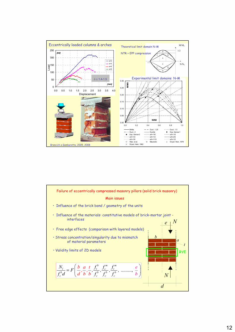
Eccentrically loaded columns & arches
Experimental set up
12
0
50
100
150
200
250
0.0 0.5 1.0 1.5 2.0 2.5 3.0 3.5 4.0
[mm]
[kN]
e=0
e=4
e=6
e=8
Spostamento
Carico
Displacement
Load
δ ≅ 1.4-1.5
0.00
0.05
0.10
0.15
0.20
0.25
0.30
0.0 0.2 0.4 0.6 0.8 1.0
N/N0
M/M0
Brittle Duct.: 1.25 Duct.: 1.5
Duct.: 2 Ductile Exp. Genoa-1
Exp. Genoa-2 e/h=1/6 e/h=1/5
e/h=1/4 e/h=1/3 e/h=2/5
e/h=1/8 e/h=1/15 e/h=1/2
Hatz. et al. Maurenbr. Drysd. Ham, 1979
Drysd. Ham, 1982
Experimental limit domains N-M
A
A
B
B C
C
D
D
1/2
1 − N/No
M/Mo
Brencich e Gambarotta, 2005, 2008
Theoretical limit domain N-M
NTR + EPP compression
Eccentrically loaded columns & arches
Main issues
Failure of eccentrically compressed masonry pillars (solid brick masonry)
• Influence of the materials: constitutive models of brick-mortar joint -interfaces
• Free edge effects (comparison with layered models)
• Stress concentration/singularity due to mismatch of material parameters
• Influence of the brick bond / geometry of the units
........., b m m
l t c t
b b b b
c c c c
b a t, ,
d b
N f f fF , , , ,
f d f f bfb
e =
• Validity limits of 2D models
N
N
e
ab
t
d
RVE

13
N
M
l
N
M
N
M
l
N
M
l
0
h /2a
yb
y
h /2b
0x
xB
a
Bb
S
h
2a
h
2b
x
y
l
ha
h
2b
h
2b
Bb
Ba
Bb
Periodic cell
REV
symmetry
( ) ( ) ( ) ( ) ( )0 0 0
1 1
, aMN
a p p d a
nm n m
n m
x y a f x r f x a f x g y= =
Φ = + + ∑∑
( ) ( ) ( ) ( ) ( )0 0 0
1 1
, bMN
b p p d b
nm n m
n m
x y a f x r f x b f x g y= =
Φ = + + ∑∑
Assumed tension field
+ BC’s on f() and g()
+ plastic admissibility - Mohr-Coulomb criterion
+ unilateral – frictional brick-layer interface
max
T
eq
att
N = ≤ = ≤
c a
S a d
A a 0
A a 0
ɶPPLIN
Eccentrically loaded columns & arches
LB strength of stacked bond prisms
Influence of the RVE height/width ratio
x
y
x
y
M=0
N
130h mm=
55 d mm=
x
y
x
y
M=0
N
65h mm=
120 d mm=
x
y
x
y
M=0
N
65h mm= 250 d mm=
xxσ
yyσ
xyσ
0.4
0.6
0.8
1.0
0 50 100 150 200 250
h [mm]
N0 / f
cbh
extended layered medium
present model
0.88 -
d (mm)
Concentric axial force

14
Eccentric axial force
Vertical compressive stressat the limit state
0e =
12
he =
6
he =
4
he =
3
he =
[N/mm2]
0.0
0.1
0.2
0.3
0.4
0.5
0.6
0.0 0.2 0.4 0.6 0.8 1.0N / N 0
M / M
0
present model
homogeneous beam
e = h
/3
e = h/4
e = h/6
e = h /12
N-M limit domain
NTR-EPP homogeneous beam
• No influence of the friction coefficientin the range [ ]0 0 6, .µ∈
( )2
0 0 0
1, 0
2
M N Nf N M
M N N
= + + =
Limit domain of NTR-EPP (NoTensileResistant – ElasticPerfectlyPlastic)
homogeneous beam
2
0 0 4 4c
MM N d f d= =
0 c
MN f d=
3. Masonry arch bridges
ε
σ
σ0
ε el
Incremental analysis – Castigliano2D - Homogeneous beam model
G
σ'c
σc
no-tensile resitant area
MN
compression
h
x
yuni-axial model
NRT+ EPP compression
Brencich et al, 2003

15
Limit analysis - NTR modelHypotheses:
1. No tensile resistance NTR 2. Unbounded compressive strength
3. No sliding failure admitted 4. Small displacement and rotations
Trust line
µs f
b0
c s max .=µ µµ µµ µµ µSafe theorem
Statically admissible stress fields
Kooharian, Heyman, ………..
G
G
G2 2
'
'
1
C1
'
C1
G1
−θ11θ
−θ2θ2
2C 2C'
s
kµ q
u+
u−
1θ sµc
uv
( ) ( )k hb u s ds q u s ds v v= −∫ ∫ɺ ɺµ γµ γµ γµ γS S
Kinematic theorem c k min=µ µµ µµ µµ µ
Kinematically admissible mechanisms
rh 165=
sh 220=
1428f =
6550=ℓ
a 1 4= ℓb 300=
2000′=ℓ 2000′ =ℓ
Masonry bridges:Vault – fill interaction
Prestwood Bridge hinges
Live load
Tests on full scale masonry bridges: Prestwood Bridge
Page, 1993
Heavy not resisting fill
P 46kNu =
P 228kNexp =

16
(Royles & Hendry, 1991)
Tests on model scale bridges
Vault and fill
Vault
Complete bridge
v ( mm )
Total load applied
F ( kN)
cFfill
Fc
c
c
F4
F
fill
≅≅≅≅
Crisfield (1985)
Choo et al. (1991)
Bicanic et al. (2003)
Owen et al. (1998)
Sperimentazione su modelli – Effetto del riempimento - A. Brencich

17
Sperimentazione su modelli – Effetto del riempimento - A. Brencich
Two dimensional model of the bridgeTwo dimensional model of the bridge
Spandrel walls
Fill
Fill
Vaults
PierBacking
Fill: frictional-cohesive material
Arches and piers:NTR, ductile in compression beams
The two-dimensional model isobtained by neglecting the in plane resistance of the spandrels
Why a two-dimensional model ? - Focus on longitudinal collapse mechanisms and arch-fill interaction
- Difficulties in describing the 3D behaviour of materials and components
Limits of validity - Interaction between longitudinal and transverse collapsemechanisms(within the objectives of
the research)

18
1x2x
3x
Spandrelwalls
Fill
13 23 0τ τ= =
Assumptionsabout the fill:
c 33 0σ−σ ≤ ≤ɶ
,3 0ijσ =
Effects of spandrel walls on fill resistanceEffects of spandrel walls on fill resistance
The effects of spandrels and tie-rods on the fill resistance(due to the containing effect) are approximately taken intoaccount by limiting the out-of plane stress
33σ
Spandrel walls
2x
3x
33σ 33σ
Arch barrel
The plane state conditions necessary to obtain a two-dimensional description of the fill implyan underestimation of its resistance (safe assumptions for the fill resistance)
The resistance of the fill is affected by the containingcapacity of the spandrels, which has to be taken intoaccount also in a plane model of the fill
Method of analysis: Limit Analysis approach Method of analysis: Limit Analysis approach
Limit Analysisapproach
Lower Bound
Upper Bound
Equilibrium model
(C & G, 2007)
Compatible model
(C & G, 2005, 2006)
Assumptions (and limits)- Associated flow rule
- Ductile behaviour
- Small displacements
Why Limit Analysis ? - Reduction of the number of constitutive parameters withrespect to an incremental analysis (reduction of uncertainties)
- Direct evaluation and description of the collapse configuration
- Evaluation of a range of values within which the true collapsload of the mechanical model is contained
A range of values isobtained within whichthe true collapse load of the mechanicalmodel is contained

19
Admissible domains: arches and beamsAdmissible domains: arches and beams
( )b b
p p p
M 2N Nf 1 0
M N N
= + + ≤
σσσσ
p cN bh= σ2
p c
1M bh
4= σ
pM M
pN N
1 2−1−
cσ
N
M
NTR, ductile in compression beam
Admissible domain
Associated flow rule
( )Sign M;
hχ= λɺɺ
p
1 2N1
2 N
ε= + λ ;
ɺɺ λ≥0ɺ
1 2
( ) ( ) ( )21 2
mc 11 22 12 11 22f 4 sin 2ccos 0σ σ τ σ σ= − + + + ϕ− ϕ ≤σσσσ
( ) ( ) ( ) ( )22 2
mc 11 22 12 11 22 3
2 sin4ccosf 4 sin 0
sin sinσ σ τ σ σ σ
1− ϕϕ= − + + + ϕ − − ≤
1+ ϕ 1+ ϕσσσσ
( ) ( ) ( ) ( )23 2
mc 11 22 12 11 22 3
2 sin4ccosf 4 sin 0
sin sinσ σ τ σ σ σ
1+ ϕϕ= − + − + ϕ− − ≤
1− ϕ 1− ϕσσσσ
( ) ( ) ( )2 2
t 11 22 12 11 22f 4 0σ σ τ σ σ= − + + + ≤σσσσ
max
3 3 cσ = σ ≥ −σɶ
max
3 1 2
1 sin 2ccosmin( , )
1 sin 1 sinσ σ σ − ϕ ϕ
= + =+ ϕ + ϕ ( ) ( )2 2
11 22 11 22 12
1 sin 2ccos1 1 42 2 1 sin 1 sin
σ σ σ σ τ − ϕ ϕ + − − + + + ϕ + ϕ
( ) ( ) ( )2 2
mc 11 22 11 22 12 c
1 sin 4ccosf 4 2 0
1 sin 1 sinσ σ σ σ τ σ + ϕ ϕ
= − + + − + − − ≤− ϕ − ϕ
ɶ ɶσσσσ
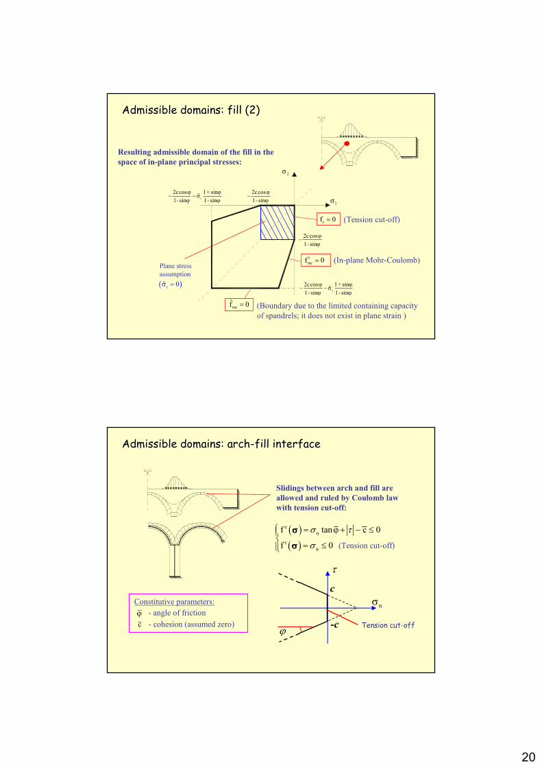
Admissible domains: fill (1)Admissible domains: fill (1)
(1)
(2)
(3)
(Mohr-Coulomb criterion in the plane of the model)
(Containing stress delimitation)
(Tension cut-off)
Maximum allowed containing stress from spandrels
- angle of internal friction
c
ϕ- cohesion
cσɶ - Allowed containing stress (from spandrel)
Constitutive parameters:Mohr-Coulomb criterion, out-of-plane components:
Maximum admissible
out-of-plane stress 3σ
(Minimum thrust on
the spandrels)
3 cσ ≥ −σɶ
20
1σ
2σ
2ccos 1+ sin
1- sin 1- sinc
ϕ ϕ− − σ
ϕ ϕɶ
2ccos 1+ sin
1- sin 1- sinc
ϕ ϕ− − σ
ϕ ϕɶ
2ccos
1- sin
ϕ−
ϕ
2ccos
1- sin
ϕ−
ϕ
1
mcf 0=
tf 0=
mcf 0=ɶ
Resulting admissible domain of the fill in the
space of in-plane principal stresses:
Plane stress
assumption
( )0c
σ =ɶ
Admissible domains: fill (2)Admissible domains: fill (2)
(Boundary due to the limited containing capacity
of spandrels; it does not exist in plane strain )
(Tension cut-off)
(In-plane Mohr-Coulomb)
Admissible domains: archAdmissible domains: arch--fill interfacefill interface
Slidings between arch and fill are
allowed and ruled by Coulomb law
with tension cut-off:
( )( )
c
n
t
n
f tan c 0
f 0
σ τ
σ
= ϕ+ − ≤
= ≤
σσσσ
σσσσ
nσc
-cϕ
τ
Tension cut-off
(Tension cut-off)
- angle of friction
c
ϕ- cohesion (assumed zero)
Constitutive parameters:

21
FE FE discretizationdiscretization of the bridgeof the bridge
Interface
elements
Triangular
elements
Beam elements
Discontinuity allowed between
triangular elements
EquilibriumEquilibrium model: model: beambeam elementelement
ξξξξ
νννν
i j
Fiν
iFξC i
F jν
Fj
ξ
Cj
ξ
( )t ξ
( )m ξ
b
F
F
C
r
r r
r
ξ
ν
=
s( )
( )( )b
N
M
ξξ
ξ
=
σσσσ
( ) ( ) ( )2
T
b
1 1N F 1 0
2 2
=− + − + −
bi
ξ
ξ ξ ξξ τ τ ξ ξξξξl l l
l l l
( ) ( ) ( )
( ) ( )
2
2 2
2 3
2 2 2 T
b
1 h 1 1 1M C F 1 0 1 0
2 2 2 3
1 h 1 1,
4 6 2
=− − − − + − +
− + −
b
i i
ν ν
ξ ξ ξ ξξ ξ τ σ
ξ ξτ σ ξ νννν
l ll l l l l
l l l ll l l
( ) ( ) ( ) ( )b b b b b b
i i h h k kξ ξ ξ ξ+ + += D s D D dσ σ σσ σ σσ σ σσ σ σ
h
k
-t
i
jh
k
t
νννν
ξξξξ
νννν
ξξξξ
νννν
ξξξξ
1 2
1 2−1−
p
M
M
p
N
N
bf 0=k+
bf 0=k-
bf 0=
( ) ( )T
b b b bξ ξ= − ≤f N r 0σσσσ
s
1
p 1t
tξ
−=
−l ( )T
b b b b ,t
tξ= − ≤f N r 0σσσσ s1...pt=
Internal force vectorfrom equilibrium
The discrete admissible domain is inside the original one in order to maintain the lower bound property of the load multiplier

22
CompatibleCompatible model: model: beambeam elementelement
h
k
-t
i
jh
k
t
νννν
ξξξξ
νννν
ξξξξ
νννν
ξξξξ
1 2
1 2−1−
p
MM
p
NN
ɺεεεε
α
β
1∆ ɺuα
2∆ ɺuα
2∆ ɺϑ1∆ ɺϑ
ɺϑi
ɺϑ j
ɺ iuβ
ɺ juβ
ɺ juα
2
1
i j
ɺ iuα
ɺmuα
m
e e e= B uɺ ɺεεεε e
i
i
i
j
j
j
m
u
u
u
u
u
α
β
α
β
α
ϑ
ϑ
=
u
ɺ
ɺɺ
ɺ ɺ
ɺɺ
ɺ
e eT e e= − ≤f N r 0σσσσ e e e= N ɺɺε λε λε λε λ
1
1e
2
2
u
u
α
α
ϑ
ϑ
∆ ∆= ∆ ∆
ɺɺ
ɺɺɺ
εεεε
e e e
b− =B u N 0ɺɺ λλλλ
e T e
p bD = r ɺλλλλ( )( )
be
b
0
l
=
σσσσσσσσ
σσσσ
Compatibility
Dissipated
power
Two hinges at ends
Associated
flow rule
The discrete admissible domain is outside the original one in order to maintain the upper bound property of the load multiplier
EquilibriumEquilibrium model: model: triangulartriangular elementelement
i
j
h { }T
11 22 12
h h h hσ σ τ=σσσσ
{ }T
11 22 12
j j j jσ σ τ=σσσσ
{ }T
11 22 12
i i i iσ σ τ=σσσσ
( ) ( ) ( ) ( )11
22
12
N N Ni i j j h h
σστ
= = + +
x x x xσ σ σ σσ σ σ σσ σ σ σσ σ σ σ
( )N p q
pqδ=x
( ) 1 2Ni i i ia x b x c= + +x
11,1 12,2 1 0bσ τ+ + =
12,1 22,2 2 0bτ σ+ + =
t t t t
i i j j h h+ + + =D D D d 0σ σ σσ σ σσ σ σσ σ σ1x
2x
Discretized limitdomain
11σ
22σ
12τ
( )( ) ( )T ≤f x = N x r 0σ σ −σ σ −σ σ −σ σ −
( ) T ,k k ≤f = N r 0σ σ −σ σ −σ σ −σ σ − , ,k i j h=
( )xσσσσ linearly
interpolated
Equilibrium
Plastic admissibility
23
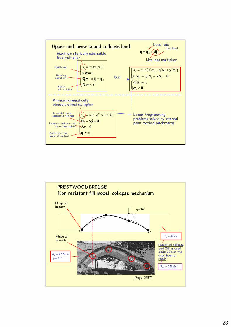
Upper and Upper and lowerlower boundbound collapsecollapse loadload
Equilibrium
Plastic admissibility
Dead load
Live load multiplier
0 s= +q q q
( )lb s
s 0
T
s max s ,
,
s ,
.
=
= ≤
C c
Q q q
N r
σ =σ =σ =σ =
σ −σ −σ −σ −
σσσσ
( )T T T
lb 0 3
T T
3
T
3
s min ,
,
1,
.
= + + + + =
= ≥
c q y
C Q Y 0
q
0
1 21 21 21 2
1 21 21 21 2
2222
α α αα α αα α αα α α
α α αα α αα α αα α α
αααα
αααα
Maximum statically admissibleload multiplier
Dual
Linear Programmingproblems solved by internalpoint method (Mehrotra)
Live load
( )0T T
ub
T
s min
1
= +
−
= =
q v r
Bv Ν 0
Av 0
q v
ɺ
ɺ
λλλλ
λ =λ =λ =λ =
Minimum kinematicallyadmissible load multiplier
Compatibility and associated flow rule
Boundaryconditions
Boundary conditions and internal constraints
Positivity of the power of live load
PRESTWOODPRESTWOOD BRIDGEBRIDGE
Hinge at impost
Hinge at haunch
Non Non resistantresistant fillfill model: model: collapsecollapse mechanismmechanism
P 46kNu =
4.5MPaσ =co37ϕ =
030η=
expP 228kN=
(Page, 1987)
Numerical collapseload (fill as dead load): 20% of the experimentalresult
24
maxγ 1
max 10γ −⋅ 2
max 10γ −⋅ 3
max 10γ −⋅ 4
max 10γ −⋅
(b)
(c) maxγ 1
max 10γ −⋅ 2
max 10γ −⋅ 3
max 10γ −⋅ 4
max 10γ −⋅
(b)
(c)
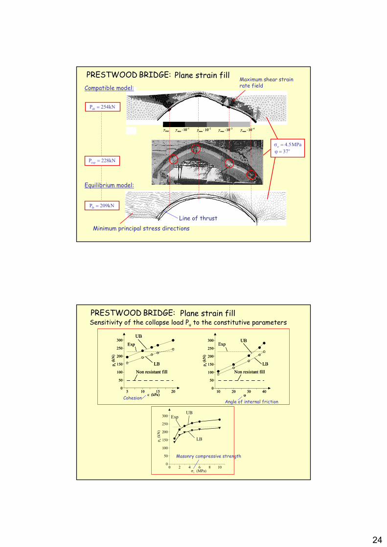
4.5MPaσ =co37ϕ =
expP 228kN=
PRESTWOODPRESTWOOD BRIDGE:BRIDGE: PlanePlane strainstrain fillfill
ubP 254kN=
lbP 209kN=
Compatible model:
Equilibrium model:
Line of thrust
Minimum principal stress directions
Maximum shear strainrate field
PRESTWOODPRESTWOOD BRIDGE:BRIDGE:SensitivitySensitivity of the of the collapsecollapse load load PPuu toto the the constitutiveconstitutive parametersparameters
5 10 15 20c (kPa)
0
50
100
150
200
250
300
pu (kN
)
UB
LB
Non resistant fill
Exp
5 10 15 20c (kPa)
0
50
100
150
200
250
300
pu (kN
)
UB
LB
Non resistant fill
Exp
0 2 4 6 8 10σc (MPa)
0
50
100
150
200
250
300
pu (kN
)
( )
UB
LB
Exp
.
10 20 30 40ϕ
0
50
100
150
200
250
300
pu (kN
)
LB
UB
Non resistant fill
Exp
10 20 30 40ϕ
0
50
100
150
200
250
300
pu (kN
)
LB
UB
Non resistant fill
Exp
Masonry compressive strength
Angle of internal frictionCohesion
PlanePlane strainstrain fillfill

25
0 20 40 60σ3 (kPa)
0
25
50
75
100
125
150
175
200
225
pu (kN
)
63− 30− 10−20− 0 ( kPa)
In-plane Mohr-Coulomb limit domain activation:
Containing stress distribution:
PRESTWOODPRESTWOOD BRIDGEBRIDGEEffectsEffects of the of the containingcontaining stress of the stress of the spandrelsspandrels
0 20 40 60σ3 (kPa)
0
25
50
75
100
125
150
175
200
225
pu (kN
)
20− 10−15− 5− 0 ( kPa)
In-plane Mohr-Coulomb limit domain activation:
Activation of the containing stress limit condition:
Containing stress distribution:Localisation of collapse under the live load position
PRESTWOODPRESTWOOD BRIDGEBRIDGEEffectsEffects of the of the containingcontaining stressstress

26
0 20 40 60σ3 (kPa)
0
25
50
75
100
125
150
175
200
225
pu (kN
)
Activation of the containing stress limit condition:
Localisation of collapse under the live load position
PRESTWOODPRESTWOOD BRIDGEBRIDGEEffectsEffects of the of the containingcontaining stressstress
Results obtained by avoiding plastic strains in the fillbelow the position of the applied live load: in this case the reduction of the collapse load is very small
This result shows that a diffused deep reduction of the fill resistance due to a limited containing stress from spandrels does not affect the result, once localised effects under the load are avoided
Prestwood Bridge
Load\deflection curve and ductility demand
Masonry ductility:
c
εδ =ε
Vertical displacement v
0 1 2 3 4 5 6 7 8
v/ℓ (*10-4)
0
0.1
0.2
0.3
0.4
0.5
0.6
0.7
0.8
Pu /(cℓ
2)
1δ =2δ =
3δ =
c = 0.01 MPaφ = 37
o
σc = 4.5 MPa
Upper boundUpper boundIncremental analysis
4(*10 )
27
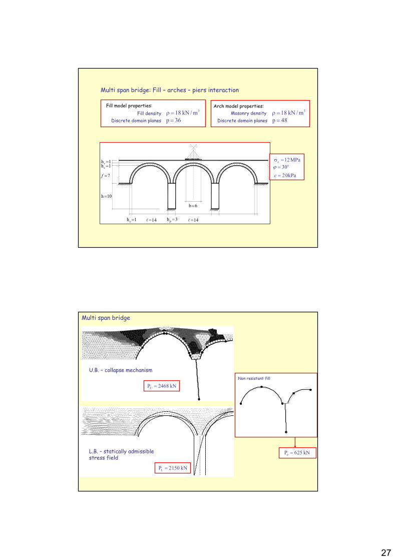
Multi span bridge: Fill – arches – piers interaction
Discrete domain planes
Arch model properties:
p 36=Fill density
318 kN /mρ = Masonry density
Fill model properties:3
18 kN /mρ =Discrete domain planes p 48=
b 6=
rh 1=
sh 1=
7=f
h 10=
sh 1= =14ℓ p
h 3= =14ℓ
12MPaσ =co30ϕ =
20kPac =
Non resistant fill
P 625 kNu =
UP 2468 kN=
Multi span bridge
U.B. – collapse mechanism
L.B. – statically admissible stress field
LP 2150 kN=

28
Probabilistic models of masonry arches (including non-linear material response)
� Monte Carlo simulation + Limit Analysis (Ng and Fairfield, 2002)� Fuzzy non linear analysis (Biondini et al., 2002)� Probabilistic Limit Analysis -Hystorical Buildings (Augusti et al., 2001, 2002)
(Schueremans & van Gemert, 2006)
Masonry pillars:Stress-strain resultsand statistical summary
Uniaxial compression
M
N
Pcfɶ
( ) 2
1, , 1 0
2c
c c c
MN NN M f
bhf bhf bh f
= + + =
ɶɶ ɶ ɶ
φ
Probabilistic limit domain of the GH
N
M
fc 0,5fc 1,5fc 2fc
Effect of the compressive strength
P P2
1
F c
Nf
Mbh
N
= ≤ − +
ɶ
Probability of failure of the masonry section
Hypotheses:
� the compressive strength is a random variable
� which is correlated in the section
� the tensile strength is deterministically vanishing
depending on the random variable
Probabilistic limit domain of the generalized hinge
cfɶ
N
M
N*
CDF PDF
cfɶ
29
N
M
2q
q
j
1
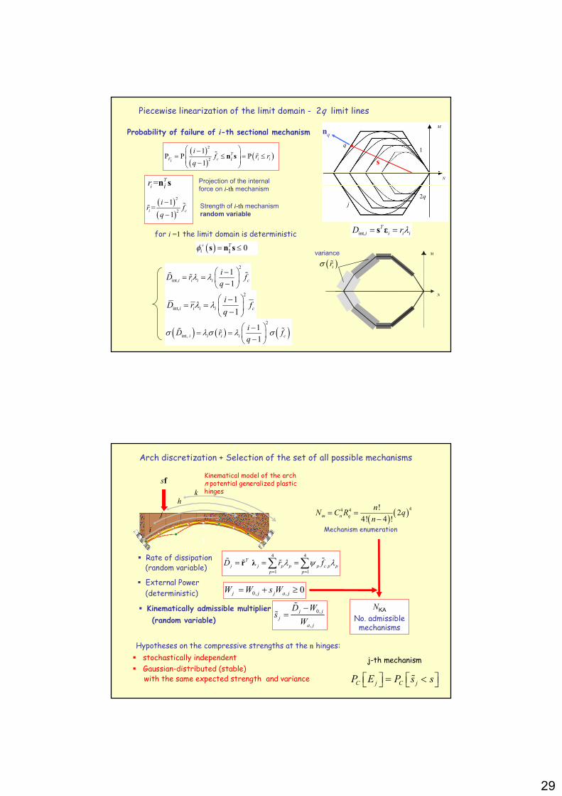
Piecewise linearization of the limit domain - 2q limit lines
s
( )( )
( )2
2
1P P P
1
T
F c i ii i
if r r
q
− = ≤ = ≤ −
n sɶ ɶ
= T
i ir n s
( )1 1 0 T+ = ≤s n sφ
Probability of failure of i-th sectional mechanism nq
for i =1 the limit domain is deterministic
( )( )
2
2
1=
1i c
ir f
q
−
−ɶɶ
Projection of the internal
force on i-th mechanism
Strength of i-th mechanism
random variable
int,
T
i i i iD r= =s ε λ
N
M
( )irɶσvariance
2
int,
1
1i i i i c
iD r f
q
−= = −
ɶɶ ɶλ λ
2
int,
1
1i i i i c
iD r f
q
−= = −
λ λ
( ) ( ) ( )2
int,
1
1i i i i c
iD r f
q
−= = −
ɶɶ ɶσ λσ λ σ
Arch discretization + Selection of the set of all possible mechanisms
i
j
hk
sf
( )( )44 4 !2
4! 4 !m n q
nN C R q
n= =
−
Kinematical model of the archn potential generalized plastic hinges
Mechanism enumeration
� External Power
(deterministic) 0, , 0j j j a jW W s W= + ≥
0,
,
j j
j
a j
D Ws
W
−=ɶ
ɶ� Kinematically admissible multiplier
(random variable)
� Rate of dissipation(random variable)
4 4
1 1
T
j j p p p c p p
p p
D r f= =
= = =∑ ∑r λ ɶɶ ɶ ɶ λ ψ λ
NKANo. admissible mechanisms
Hypotheses on the compressive strengths at the n hinges:
� stochastically independent
� Gaussian-distributed (stable)with the same expected strength and variance
C j C jP E P s s = < ɶ
j-th mechanism

30
Masonry bridges: probabilistic analysis
c.o.v.
15%
6,45m
11,25m
17,70m
sP sP sP sP
1,00sP
0,665sP
1,137sP
0,935sP 0,263sP
1
2
3
4 5 6
7
8
9
450 kN 450 kN
sP
N
M
1
4,9
6
1
4
6
9
sP sP sP
1200 1250 1300 1350 1400 1450 15000
0.2
0.4
0.6
0.8
1
1.2
1.4
1.6
1.8
2x 10
−3
s
P(s
)
U.B.
L.B.
CDF
10-3
First mechanism
Prarolo Bridge, Genoa, 40m span
[ ] j
j
E E = ∪� Collapse of the arch(realization of at least one event)
� CORNELL bounds
( ) [ ] ( )C C Cmax P P E 1j j
j
E P E≤ ≤ ≤∑good approximations for small probabilities <<10-3
c.o.v.
15%
Masonry railway bridges
Open problems
� 2D vs. 3D modeling
� Interactions among structural
elements (spandrel walls……….)
� Uncertainty of material properties
� Non linear analysis including
damage and cracking
� Dynamic response to time-
varying loadings
� Foundation settlements
� Material degradation
?


![08 Architravi, Archi e Piattabande, Volte[1]](https://static.fdocumenti.com/doc/165x107/553c04ad5503467a438b4812/08-architravi-archi-e-piattabande-volte1.jpg)