![LE VALVOLE (PARTE I) [Sola lettura] - itisforli.it · Valvole di regolazione. Otturatore a profilo parabolico. Albero di acciaio al 13% di Cromo con filettatura a passo fine per una](https://static.fdocumenti.com/doc/165x107/5bbcf70409d3f2fe038bbd53/le-valvole-parte-i-sola-lettura-valvole-di-regolazione-otturatore-a-profilo.jpg)
ACTUATORLINE – ELM series - Consultation du stock...
27
www.rollon.com ACTUATORLINE – ELM series
Transcript of ACTUATORLINE – ELM series - Consultation du stock...
www.rollon.com
ACTUATORLINE – ELM series
@ Nota: tutti i disegni riprodotti nel presente stampato sono disponibili sul sito www.rollon.com formato CAD
Indice- Contents
Il sistema - The system 5
I componenti - The components 6
Il sistema di traslazione - The linear motion system 7
Vista generale e caratteristiche tecniche principaliGeneral view and main technical characteristics 8
01IC 05 MLE - PS 05 MLE
11IC 56 MLE - PS 56 MLE
21IC 08 MLE - PS 08 MLE
31IC 011 MLE - PS 011 MLE
Tipologie di trasmissione - Transmission features :Riduttori epicicloidali - Planetary gears 14
Riduttori a vite senza fine - Worm gears 15
Alberi sporgenti - Simple shafts 16
Alberi cavi - Hollow shafts 17
Unità lineari in parallelo - Linear units in parallel 18
Lubrificazione - Lubrication 19
Montaggio e accessori - Assembly 02seirossecca dna
Protezioni - Protections 22
Dati tecnici supplementari - Additional technical data 23
Sistemi multiasse - Multiaxis systems 24
Codici di identificazione - Identification codes 26
Scheda dati - Data sheet 27

@ All the drawings in this catalogue are available in CAD files on www.rollon.com
@ Nota: tutti i disegni riprodotti nel presente stampato sono disponibili sul sito www.rollon.com formato CAD
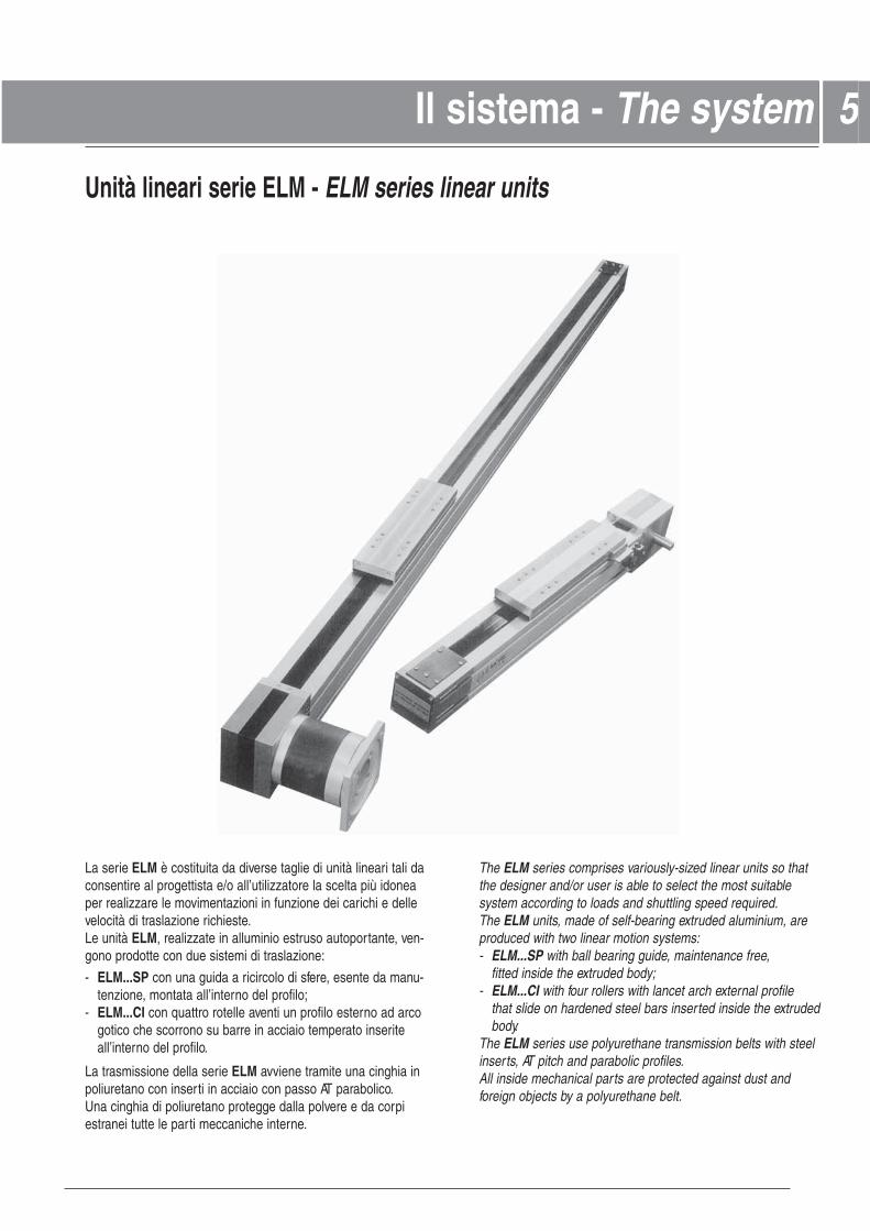
La serie ELM è costituita da diverse taglie di unità lineari tali daconsentire al progettista e/o all’utilizzatore la scelta più idoneaper realizzare le movimentazioni in funzione dei carichi e dellevelocità di traslazione richieste.Le unità ELM, realizzate in alluminio estruso autoportante, ven-gono prodotte con due sistemi di traslazione:
- ELM...SP con una guida a ricircolo di sfere, esente da manu-tenzione, montata all’interno del profilo;
- ELM...CI con quattro rotelle aventi un profilo esterno ad arcogotico che scorrono su barre in acciaio temperato inseriteall’interno del profilo.
La trasmissione della serie ELM avviene tramite una cinghia inpoliuretano con inserti in acciaio con passo AT parabolico.Una cinghia di poliuretano protegge dalla polvere e da corpiestranei tutte le parti meccaniche interne.
The ELM series comprises variously-sized linear units so thatthe designer and/or user is able to select the most suitablesystem according to loads and shuttling speed required.The ELM units, made of self-bearing extruded aluminium, areproduced with two linear motion systems:- ELM...SP with ball bearing guide, maintenance free,
fitted inside the extruded body;- ELM...CI with four rollers with lancet arch external profile
that slide on hardened steel bars inserted inside the extruded body.
The ELM series use polyurethane transmission belts with steelinserts, AT pitch and parabolic profiles.All inside mechanical parts are protected against dust andforeign objects by a polyurethane belt.
5
Unità lineari serie ELM - ELM series linear units
I componenti - The componentsIl sistema - The system
@ All the drawings in this catalogue are available in CAD files on www.rollon.com
Extruded bodies
The anodised aluminium extrusions used for the bodies of theRollon ELM series linear units were designed and manufac- tured in co-operation with a leading company in this field toobtain the right combination of high mechanical strenght andreduced weight. Aluminium alloy 6060 was used (see physical-chemical characteristics on page 23). The dimensional toleran-ces comply with UNI 3879 standards. Side slots are provided forfast, trouble-free mounting.
Carriage
The carriage of the Rollon ELM series linear units is made entirely of anodised aluminium. The dimensions vary dependingon the type. It consists of three parts to allow a sealing strip topass through. For added protection, it is also fitted with specificseals (brushes) inserted in the front and sides. Each carriagehas threaded holes fitted with stainless steel thread inserts.
Driving belt
The Rollon ELM series linear units use polyurethane trans- mission belts with steel inserts, AT pitch and parabolic profiles.This type of belt is ideal because of its high load transmittingcharacteristics, small dimensions and low noise. Used in con-junction with a backlash-free pulley, smooth alternating motioncan be achieved. Optimisation of the maximum belt width/bodydimension ratio enables the following performance characteri-stics to be achieved:
High speedLow noiseLow wear
Sealing strip
Rollon ELM series linear units are equipped with a polyure-thane sealing strip to protect all the parts inside the bodyagainst dust and foreign matter.The sealing strip runs the length of the body and is kept in posi-tion by micro-bearings located inside the carriage. This ensuresvery low frictional resistance as it passes through the carriage.
66 I componenti - The componentsI componenti - The componentsProfilo in alluminio
I profili autoportanti usati per le unità lineari Rollon serie ELM sono stati studiati e realizzati in collaborazione con un’a-zienda leader del settore al fine di ottenere estrusi che riescanoa coniugare doti di elevata resistenza meccanica ad un pesocontenuto. Il materiale impiegato è lega di alluminio 6060 ano-dizzato superficialmente (vedi caratteristiche fisico-chimiche apagina 23) ed estruso con tolleranze sulle dimensioni conformialle norme UNI 3879. I profili, inoltre, sono dotati di cave di fis-saggio che rendono estremamente semplice e rapido il montag-gio delle unità lineari e degli accessori.
Carro
Il carro delle unità lineari Rollon serie ELM è in alluminio anodizzato superficialmente.Le dimensioni variano in relazione ai modelli. Esso è costituitoda più parti per consentire il passaggio della cinghia di protezio-ne. È dotato, inoltre, di apposite guarnizioni (spazzole), inseritenelle parti laterali e frontali, per una ulteriore protezione. Tutti ifori di fissaggio utilizabili per il collegamento ad apparecchiatureesterne sono muniti di elicoidi in acciaio INOX.
Cinghia di trazione
Nelle unità lineari Rollon serie ELM vengono usate cinghie in poliuretano ad inserti in acciaio con passo AT a profilo para-bolico. Questa categoria di cinghie per trasmissione moto risultaottimale per l’impiego nelle unità lineari in quanto si rivela la piùefficacein presenza di alte trazioni, spazi contenuti e ove sia richiestauna bassa rumorosità. La combinazione con le pulegge a giocozero rende possibile un movimento alternato senza gioco.Avendo ottimizzato il rapporto tra larghezza massima di cinghiae le dimensioni del profilo si possono ottenere le seguenti pre-stazioni:
Alta velocitàBassa rumorosità Bassa usura
Cinghia di protezione
Le unità lineari Rollon serie ELM sono dotate di una cinghia in poliuretano a protezione di tutte le parti interne del profilodalla polvere e da corpi estranei.La cinghia è inserita nel profilo grazie a microcuscinetti alloggiatiall’interno del carro. Questo sistema consente di mantenere lacinghia, nella sua sede con valori di attrito volvente molto bassieliminando gli interventi di manutenzione.
@ Nota: tutti i disegni riprodotti nel presente stampato sono disponibili sul sito www.rollon.com formato CAD
The linear motion system has been designed to meet the loadcapacity, speed and maximum acceleration conditions. Two linearmotion systems are offered:
ELM ...SP with ball bearing guides
A ball bearing guide with high load capacity are mounted in a dedicated seat on the outer sides of the body.
The carriage is assembled on two pre-loaded ball bearing blocks.
The two ball bearing blocks enables the carriage to with-stand loading in the four main directions.
The two blocks have seals on both sides and, where necessary, an additional scraper can be fitted for very dustyconditions.
The ball bearing carriages of the SP versions are also fitted with a retention cage that eliminates "steel-steel" contact between adjacent revolving parts and prevents misalignment of these in the circuits.
Lubrication reservoirs (pockets) installed on the front of the ball bearing blocks supply the right amount of grease, thus promoting maintenance-free operation.
The linear motion system described above offers:
High speed and accelerationHigh load capacityHigh permissible bending momentsLow frictionLong lifeFree maintenanceLow noise
ELM...CI with lancet arch bearing guides inside the bodyTwo hardened steel rods (58/60 HRC hardness, tolerance h6)are securely inserted inside the body.The carriage is fitted with four journal bearing assemblieseach having a lancet arch groove machined into its outer raceto run on the steel rods.The four carriage journal bearings are mounted on steel pins, two of which are eccentric, to allow setting of running clearance and pre-load.To keep the running tracks clean and lubricated, four grease impregnated felt seals, complete with grease reservoirs, are fitted on the ends of the carriage.
The linear motion system described above offers:
Good positioning accuracyLow noiseFree maintenance
77Il sistema di traslazione - The linear motion systemIl sistema di traslazione risulta determinante per la capacità dicarico, la velocità e l’accelerazione massima.Nelle unità Rollon serie ELM vengono usati due sistemi di traslazione:
ELM...SP con guide a ricircolo di sfere
Una guida a ricircolo di sfere ad elevata capacità di carico viene fissata in una apposita sede all’interno del profilodi alluminio.
Il carro dell’unità lineare è montato su due carrelli a ricircolodi sfere precaricati.
I carrelli a ricircolo di sfere possono sopportare carichi nelle quattro direzioni principali grazie alle quattro corone di sfere.
I due carrelli sono dotati di protezioni su entrambi i lati e, dovenecessario, è possibile montare un ulteriore raschiatore perambienti molto polverosi.
I carrelli a ricircolo di sfere delle versioni SP sono inoltre dota-ti di una gabbia di ritenuta, che elimina il contatto “acciaio-acciaio” tra corpi volventi adiacenti e evita disallineamentidegli stessi nei circuiti.
Inoltre sui frontali dei carrelli a ricircolo di sfere sono installatidei serbatoi di lubrificante che erogano la giusta quantità di grasso al sistema rendendolo esente da manutenzione.
Il sistema di traslazione sopra descritto consente di ottenere:
Elevate velocità e accelerazioniElevate capacità di caricoElevati momenti ribaltanti ammissibiliBassi attritiLunghissime durateAssenza di manutenzioneBassa rumorosità
ELM...CI con guide a rotelle all’interno del profiloDue barre in acciaio temprato con durezza 58/60 HRC (tolle-ranza h6) vengono applicate al profilo nell’apposita sede mediante una operazione di cianfrinatura.Il carro è dotato di quattro rotelle a due corone di sfere a contatto obliquo, con profilo esterno ad arco gotico che consente un ottimo accoppiamento con le barre in acciaio.Le quattro rotelle del carro sono montate su perni in acciaio,di cui due eccentrici, indispensabili per le tarature ed ilprecarico del sistema.Per mantenere pulite e lubrificate le piste di scorrimentovengono inseriti, alle estremità del carro, quattro feltri intrisi con grasso di adeguata viscosità e relativo serbatoio.
Il sistema di traslazione sopra descritto consente di ottenere:
Buona precisione di posizionamentoOttima silenziositàAssenza di manutenzione
@ All the drawings in this catalogue are available in CAD files on www.rollon.com
ELM 110
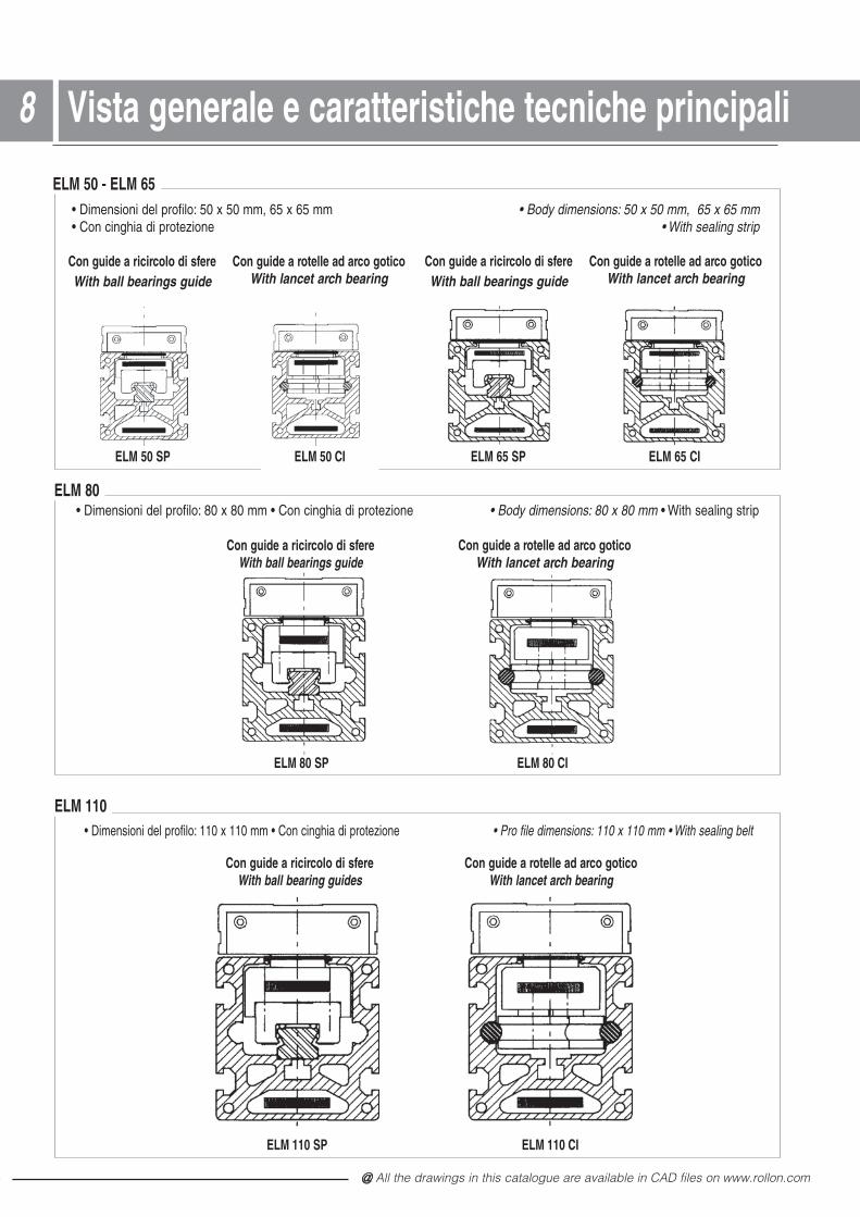
ELM 50 - ELM 65
ELM 80
• Dimensioni del profilo: 50 x 50 mm, 65 x 65 mm • Body dimensions: 50 x 50 mm, 65 x 65 mm • Con cinghia di protezione • With sealing strip
ELM 50 SP
Con guide a ricircolo di sfereWith ball bearings guide
ELM 50 CI
• Dimensioni del profilo: 80 x 80 mm • Con cinghia di protezione • Body dimensions: 80 x 80 mm • With sealing strip
ELM 65 CI
Con guide a rotelle ad arco goticoWith lancet arch bearing
ELM 65 SP
Con guide a ricircolo di sfereWith ball bearings guide
• Dimensioni del profilo: 110 x 110 mm • Con cinghia di protezione • Pro file dimensions: 110 x 110 mm • With sealing belt
ELM 80 SP
Con guide a ricircolo di sfere
ELM 80 CI
ELM 110 SP
Con guide a ricircolo di sfereWith ball bearing guides
ELM 110 CI
Con guide a rotelle ad arco goticoWith lancet arch bearing
Con guide a rotelle ad arco goticoWith lancet arch bearing
Vista generale e caratteristiche tecniche principali88
Con guide a rotelle ad arco goticoWith lancet arch bearing With ball bearings guide
@ Nota: tutti i disegni riprodotti nel presente stampato sono disponibili sul sito www.rollon.com formato CAD
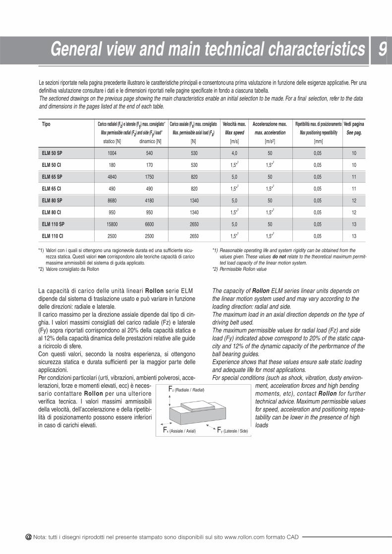
99General view and main technical characteristicsLe sezioni riportate nella pagina precedente illustrano le caratteristiche principali e consentono una prima valutazione in funzione delle esigenze applicative. Per unadefinitiva valutazione consultare i dati e le dimensioni riportati nelle pagine specificate in fondo a ciascuna tabella.The sectioned drawings on the previous page showing the main characteristics enable an initial selection to be made. For a final selection, refer to the dataand dimensions in the pages listed at the end of each table.
Tipo Carico radialel (Fz) e laterale (Fy) max. consigliato*1 Carico assiale (Fx) max. consigliato Velocità max. Accelerazione max. Ripetibilità max. di posizionamento Vedi pagina
Max permissible radial (Fz) and side (Fy) load*1 Max. permissible axial load (Fx) Max speed max. acceleration Max positioning repeatibility See pag.
statico [N] dinamico [N] [N] [m/s] [m/s2] [mm]
ELM 50 SP 1004 540 530 4,0 50 0,05 10
ELM 50 CI 180 170 530 1,5*2
1,5*2
0,05 10
ELM 65 SP 4840 1750 820 5,0 50 0,05 11
ELM 65 CI 490 490 820 1,5*2
1,5*2
0,05 11
ELM 80 SP 8680 4180 1340 5,0 50 0,05 12
ELM 80 CI 950 950 1340 1,5*2
1,5*2
0,05 12
ELM 110 SP 15800 6600 2650 5,0 50 0,05 13
ELM 110 CI 2500 2500 2650 1,5*2
1,5*2
0,05 13
*1) Valori con i quali si ottengono una ragionevole durata ed una sufficiente sicu-rezza statica. Questi valori non corrispondono alle teoriche capacità di caricomassime ammissibili del sistema di guida applicato.
*2) Valore consigliato da Rollon
*1) Reasonable operating life and system rigidity can be obtained from thevalues given. These values do not relate to the theoretical maximum permit-ted load capacity of the linear motion system.
*2) Permissible Rollon value
La capacità di carico delle unità lineari Rollon serie ELM dipende dal sistema di traslazione usato e può variare in funzionedelle direzioni: radiale e laterale.Il carico massimo per la direzione assiale dipende dal tipo di cin-ghia. I valori massimi consigliati del carico radiale (Fz) e laterale(Fy) sopra riportati corrispondono al 20% della capacità statica eal 12% della capacità dinamica delle prestazioni relative alle guidea ricircolo di sfere.Con questi valori, secondo la nostra esperienza, si ottengonosicurezza statica e durata sufficienti per la maggior parte delleapplicazioni.Per condizioni particolari (urti, vibrazioni, ambienti polverosi, acce-lerazioni, forze e momenti elevati, ecc) è neces-sario contattare Rollon per una ulter iore verifica tecnica. I valori massimi ammissibilidella velocità, dell’accelerazione e della ripetibi-lità di posizionamento possono essere inferioriin caso di carichi elevati.
The capacity of Rollon ELM series linear units depends on the linear motion system used and may vary according to theloading direction: radial and side.The maximum load in an axial direction depends on the type ofdriving belt used.The maximum permissible values for radial load (Fz) and sideload (Fy) indicated above correspond to 20% of the static capa-city and 12% of the dynamic capacity of the performance of theball bearing guides.Experience shows that these values ensure safe static loadingand adequate life for most applications.For special conditions (such as shock, vibration, dusty environ-
ment, acceleration forces and high bendingmoments, etc), contact Rollon for fur ther technical advice. Maximum permissible valuesfor speed, acceleration and positioning repea-tability can be lower in the presence of highloads
Fz (Radiale / Radial)
Fx (Assiale / Axial) Fy (Laterale / Side)
@ All the drawings in this catalogue are available in CAD files on www.rollon.com
9
15.5
30.5
70
15.5
75.5
5010
8
60 . 3
1212
26
50
4.2
5050
0701051
80
3565
10
8181 26 2662
10150
48
50
50
6.24
60
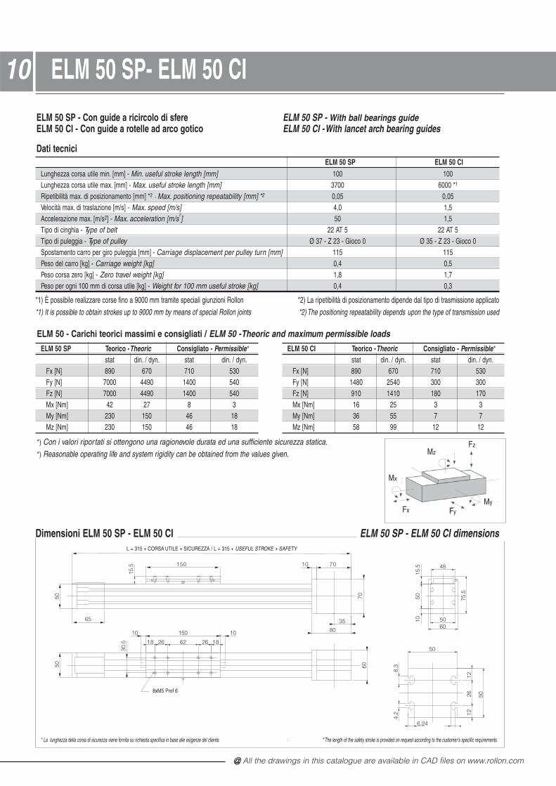
1010 ELM 50 SP- ELM 50 CI
Dimensioni ELM 50 SP - ELM 50 CI
ELM 50 SP - Con guide a ricircolo di sfereELM 50 CI - Con guide a rotelle ad arco gotico
Dati tecnici
ELM 50 SP - With ball bearings guideELM 50 CI - With lancet arch bearing guides
IC 05 MLEPS 05 MLELunghezza corsa utile min. [mm] - Min. useful stroke length [mm] 001 001Lunghezza corsa utile max. [mm] - Max. useful stroke length [mm] * 00060073 1
Ripetibilità max. di posizionamento [mm] *2 - Max. positioning repeatability [mm] *2 50,050,0Velocità max. di traslazione [m/s] - Max. speed [m/s] 5,10,4Accelerazione max. [m/s2] - Max. acceleration [m/s
2] 5,105
Tipo di cinghia - Type of belt 5 TA 225 TA 22Tipo di puleggia - Type of pulley Ø 37 - Z 23 - Gioco 0 Ø 35 - Z 23 - Gioco 0Spostamento carro per giro puleggia [mm] - Carriage displacement per pulley turn [mm] 511511Peso del carro [kg] - Carriage weight [kg] 5,04,0Peso corsa zero [kg] - Zero travel weight [kg] 7,18,1Peso per ogni 100 mm di corsa utile [kg] - Weight for 100 mm useful stroke [kg] 3,04,0
*1) È possibile realizzare corse fino a 9000 mm tramite speciali giunzioni Rollon *2) La ripetibilità di posizionamento dipende dal tipo di trasmissione applicato*1) It is possible to obtain strokes up to 9000 mm by means of special Rollon joints *2) The positioning repeatability depends upon the type of transmission used
* La lunghezza della corsa di sicurezza viene fornita su richiesta specifica in base alle esigenze del cliente. · * The length of the safety stroke is provided on request according to the customer's specific requirements.
ELM 50 SP - ELM 50 CI dimensions
ELM 50 SP Teorico -Theoric Consigliato - Permissible*
stat din. / dyn. stat din. / dyn.Fx [N] 890 670 710 530Fy [N] 7000 4490 1400 540Fz [N] 7000 4490 1400 540Mx [Nm] 42 27 8 3My [Nm] 230 150 46 18Mz [Nm] 230 150 46 18
ELM 50 CI Teorico -Theoric Consigliato - Permissible*
stat din. / dyn. stat din. / dyn.Fx [N] 890 670 710 530Fy [N] 1480 2540 300 300Fz [N] 910 1410 180 170Mx [Nm] 16 25 3 3My [Nm] 36 55 7 7Mz [Nm] 58 99 12 12
*) Con i valori riportati si ottengono una ragionevole durata ed una sufficiente sicurezza statica.*) Reasonable operating life and system rigidity can be obtained from the values given.
ELM 50 - Carichi teorici massimi e consigliati / ELM 50 - Theoric and maximum permissible loads
Fx
MzFz
Mx
FyMy
L = 315 + CORSA UTILE + SICUREZZA / L = 315 + USEFUL STROKE + SAFETY
8xM5 Prof 6
@ Nota: tutti i disegni riprodotti nel presente stampato sono disponibili sul sito www.rollon.com formato CAD
L = 415 + CORSA UTILE + SICUREZZA / L = 415 + USEFUL STROKE + SAFETY
8xM5 Prof 6
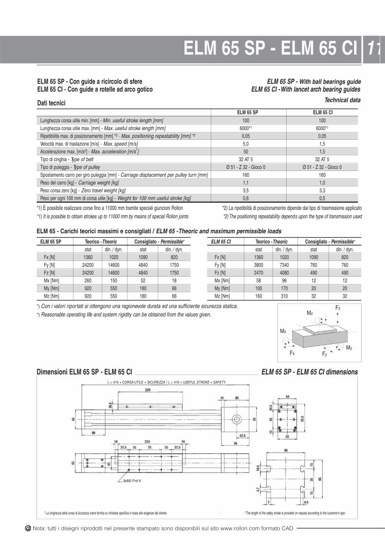
11ELM 65 SP - ELM 65 CI
* La lunghezza della corsa di sicurezza viene fornita su richiesta specifica in base alle esigenze del cliente. · * The length of the safety stroke is provided on request according to the customer's spe-
ELM 65 SP - Con guide a ricircolo di sfereELM 65 CI - Con guide a rotelle ad arco gotico
Dati tecnici
ELM 65 SP - With ball bearings guideELM 65 CI - With lancet arch bearing guides
Technical data
IC 56 MLEPS 56 MLELunghezza corsa utile min. [mm] - Min. useful stroke length [mm] 001 001Lunghezza corsa utile max. [mm] - Max. useful stroke length [mm] 6000*1 6000*1
Ripetibilità max. di posizionamento [mm] *2 - Max. positioning repeatability [mm] *2 50,050,0Velocità max. di traslazione [m/s] - Max. speed [m/s] 5,10,5Accelerazione max. [m/s2] - Max. acceleration [m/s
2] 5,105
Tipo di cinghia - Type of belt 5 TA 235 TA 23Tipo di puleggia - Type of pulley Ø 51 - Z 32 - Gioco 0 Ø 51 - Z 32 - Gioco 0Spostamento carro per giro puleggia [mm] - Carriage displacement per pulley turn [mm] 061061Peso del carro [kg] - Carriage weight [kg] 0,11,1Peso corsa zero [kg] - Zero travel weight [kg] 3,35,3Peso per ogni 100 mm di corsa utile [kg] - Weight for 100 mm useful stroke [kg] 5,06,0
*1) È possibile realizzare corse fino a 11000 mm tramite speciali giunzioni Rollon *2) La ripetibilità di posizionamento dipende dal tipo di trasmissione applicato*1) It is possible to obtain strokes up to 11000 mm by means of special Rollon joints *2) The positioning repeatability depends upon the type of transmission used
Dimensioni ELM 65 SP - ELM 65 CI ELM 65 SP - ELM 65 CI dimensions
ELM 65 SP Teorico -Theoric Consigliato - Permissible*
stat din. / dyn. stat din. / dyn.Fx [N] 1360 1020 1090 820Fy [N] 24200 14600 4840 1750Fz [N] 24200 14600 4840 1750Mx [Nm] 260 150 52 18My [Nm] 920 550 180 66Mz [Nm] 920 550 180 66
ELM 65 CI Teorico -Theoric Consigliato - Permissible*
stat din. / dyn. stat din. / dyn.Fx [N] 1360 1020 1090 820Fy [N] 3800 7340 760 760Fz [N] 2470 4080 490 490Mx [Nm] 58 96 12 12My [Nm] 100 170 20 20Mz [Nm] 160 310 32 32
*) Con i valori riportati si ottengono una ragionevole durata ed una sufficiente sicurezza statica.*) Reasonable operating life and system rigidity can be obtained from the values given.
ELM 65 - Carichi teorici massimi e consigliati / ELM 65 - Theoric and maximum permissible loads
Fx
MzFz
Mx
FyMy
8xM5 Prof 6

@ All the drawings in this catalogue are available in CAD files on www.rollon.com
1212 ELM 80 SP - ELM 80CI
* La lunghezza della corsa di sicurezza viene fornita su richiesta specifica in base alle esigenze del cliente.
ELM 80 SP - Con guide standard a ricircolo di sfere ELM 80 CI - Con guide a rotelle ad arco gotico
Dati tecnici
ELM 80 SP - With standard ball bearings guide ELM 80 CI - With lancet arch bearing guides
Technical dataIC 08 MLEPS 08 MLE
Lunghezza corsa utile min. [mm] - Min. useful stroke length [mm] 001001Lunghezza corsa utile max. [mm] - Max. useful stroke length [mm] 6000*1 6000*1
Ripetibilità max. di posizionamento [mm] *2 - Max. positioning repeatability [mm] *2 50,050,0Velocità max. di traslazione [m/s] - Max. speed [m/s] 5,10,5Accelerazione max. [m/s2] - Max. acceleration [m/s
2] 5,105
Tipo di cinghia - Type of belt 01 TA 2301 TA 23Tipo di puleggia - Type of pulley Ø 60 - Z 19 - Gioco 0 Ø 60 - Z 19 - Gioco 0Spostamento carro per giro puleggia [mm] - Carriage displacement per pulley turn [mm] 091091Peso del carro [kg] - Carriage weight [kg] 5,27,2Peso corsa zero [kg] - Zero travel weight [kg] 5,95,01Peso per ogni 100 mm di corsa utile [kg] - Weight for 100 mm useful stroke [kg] 8,00,1
*1) È possibile realizzare corse fino a 11000 mm tramite speciali giunzioni Rollon *2) La ripetibilità di posizionamento dipende dal tipo di trasmissione applicato*1) It is possible to obtain strokes up to 11000 mm by means of special Rollon joints *2) The positioning repeatability depends upon the type of transmission used
Dimensioni ELM 80 SP - ELM 80 CI
ELM 80 SP Teorico -Theoric Consigliato - Permissible*
stat din. / dyn. stat din. / dyn.Fx [N] 2230 1670 1780 1340Fy [N] 43400 34800 8680 4180Fz [N] 43400 34800 8680 4180Mx [Nm] 620 480 120 58My [Nm] 3170 2540 630 300Mz [Nm] 3170 2540 630 300
ELM 80 CI Teorico -Theoric Consigliato - Permissible*
stat din. / dyn. stat din. / dyn.Fx [N] 2230 1670 1780 1340Fy [N] 8500 17000 1700 1700Fz [N] 4740 8700 950 950Mx [Nm] 140 250 28 28My [Nm] 390 710 78 78Mz [Nm] 700 1390 140 140
* La lunghezza della corsa di sicurezza viene fornita su richiesta specifica in base alle esigenze del cliente.* The length of the safety stroke is provided on request according to the customer's specific requirements.
*) Con i valori riportati si ottengono una ragionevole durata ed una sufficiente sicurezza statica.*) Reasonable operating life and system rigidity can be obtained from the values given.
ELM 80 - Carichi teorici massimi e consigliati / ELM 80 - Theoric and maximum permissible loads
Fx
MzFz
Mx
FyMy
ELM 80 SP - ELM 80 CI dimensionsL = 540 + CORSA UTILE + SICUREZZA / L = 540 + USEFUL STROKE + SAFETY
8xM6 Prof 8

@ Nota: tutti i disegni riprodotti nel presente stampato sono disponibili sul sito www.rollon.com formato CAD
13ELM 110 SP - ELM 110 CI
* La lunghezza della corsa di sicurezza viene fornita su richiesta specifica in base alle esigenze del cliente.
ELM 110 SP - Con guide standard a ricircolo di sfere ELM 110 CI - Con guide a rotelle ad arco gotico
Dati tecnici
ELM 110 SP - With standard ball bearings guide ELM 110 CI - With lancet arch bearing guides
Technical dataIC 011 MLEPS 011 MLE
Lunghezza corsa utile min. [mm] - Min. useful stroke length [mm] 001001Lunghezza corsa utile max. [mm] - Max. useful stroke length [mm] 6000*1 6000*1
Ripetibilità max. di posizionamento [mm] *2 - Max. positioning repeatability [mm] *2 50,050,0Velocità max. di traslazione [m/s] - Max. speed [m/s] 5,10,5Accelerazione max. [m/s2] - Max. acceleration [m/s
2] 5,105
Tipo di cinghia - Type of belt 01 TA 0501 TA 05Tipo di puleggia - Type of pulley Ø 86 - Z 27 - Gioco 0 Ø 86 - Z 27 - Gioco 0Spostamento carro per giro puleggia [mm] - Carriage displacement per pulley turn [mm] 072072Peso del carro [kg] - Carriage weight [kg] 1,56,5Peso corsa zero [kg] - Zero travel weight [kg] 6,125,22Peso per ogni 100 mm di corsa utile [kg] - Weight for 100 mm useful stroke [kg] 1,14,1
*1) È possibile realizzare corse fino a 11000 mm tramite speciali giunzioni Rollon *2) La ripetibilità di posizionamento dipende dal tipo di trasmissione applicato*1) It is possible to obtain strokes up to 11000 mm by means of special Rollon joints *2) The positioning repeatability depends upon the type of transmission used
Dimensioni ELM 110 SP - ELM 110 CI
ELM 110 SP Teorico -Theoric Consigliato - Permissible*
stat din. / dyn. stat din. / dyn.Fx [N] 4410 3310 3530 2650Fy [N] 79000 55000 15800 6600Fz [N] 79000 55000 15800 6600Mx [Nm] 1300 860 260 100My [Nm] 7110 4950 1420 590Mz [Nm] 7110 4950 1420 590
ELM 110 CI Teorico -Theoric Consigliato - Permissible*
stat din. / dyn. stat din. / dyn.Fx [N] 4410 3310 3530 2650Fy [N] 19300 41700 3860 3860Fz [N] 12500 24500 2500 2500Mx [Nm] 330 650 66 66My [Nm] 960 1880 190 190Mz [Nm] 1480 3200 300 300
* La lunghezza della corsa di sicurezza viene fornita su richiesta specifica in base alle esigenze del cliente.* The length of the safety stroke is provided on request according to the customer's specific requirements.
*) Con i valori riportati si ottengono una ragionevole durata ed una sufficiente sicurezza statica.*) Reasonable operating life and system rigidity can be obtained from the values given.
ELM 110 - Carichi teorici massimi e consigliati / ELM 110 - Theoric and maximum permissible loads
Fx
MzFz
Mx
FyMy
ELM 110 SP - ELM 110 CI dimensionsL = 695 + CORSA UTILE + SICUREZZA / L = 695 + USEFUL STROKE + SAFETY
8xM8 Prof 15
@ All the drawings in this catalogue are available in CAD files on www.rollon.com
3
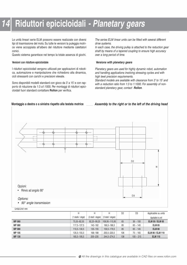
Le unità lineari serie ELM possono essere realizzate con diversitipi di trasmissione del moto. Su tutte le versioni la puleggia motri-ce viene accoppiata all’albero del riduttore mediante calettatoriconici.Questo sistema garantisce nel tempo la totale assenza di giochi.
Versioni con riduttore epicicloidale
I riduttori epicicloidali vengono utilizzati per applicazioni di roboti-ca, automazione e manipolazione che richiedono alta dinamica,cicli stressanti con carichi e precisioni elevate.
Sono disponibili modelli standard con gioco da 3’ a 15’ e con rap-porto di riduzione da 1:3 a1:1000. Per montaggi di riduttori epici-cloidali fuori standard contattare Rollon per verifica.
The series ELM linear units can be fitted with several differentdrive systems.In each case, the driving pulley is attached to the reduction gearshaft by means of a tapered coupling to ensure high accuracyover a long period of time.
Versions with planetary gears
Planetary gears are used for highly dynamic robot, automationand handling applications involving stressing cycles and withhigh level precision requirements.Standard models are available with clearance from 3' to 15' andwith a reduction ratio from 1:3 to 1:1000. For assembly of non-standard planetary gear, contact Rollon.
Montaggio a destra o a sinistra rispetto alla testata motrice
Unità/Unit: mm
H H H D2 D3 Applicabile su unità(1 stadio / stage) (2 stadi / stages) (3 stadi / stages) Appliable to unit
MP 060 75,55~82,55 92,25~99,25 108,95~115,95 65 36 ~ 100 ELM 50 / ELM 65MP 080 117,5~137,5 142~162 166,5~186,5 85 65 ~ 145 ELM 65MP 080 110,5~130,5 135~155 159,5~179,5 85 65 ~ 145 ELM 80MP 105 135,5~155,5 168~188 200,5~220,5 106 75 ~ 165 ELM 80 / ELM 110MP 130 165,5~195,5 205~235 244,5~274,5 138 100 ~ 215 ELM 110
Opzioni:Rinvio ad angolo 90°
Options:90° angle transmission
Assembly to the right or to the left of the driving head
1414 Riduttori epicicloidali - Planetary gears
@ Nota: tutti i disegni riprodotti nel presente stampato sono disponibili sul sito www.rollon.com formato CAD
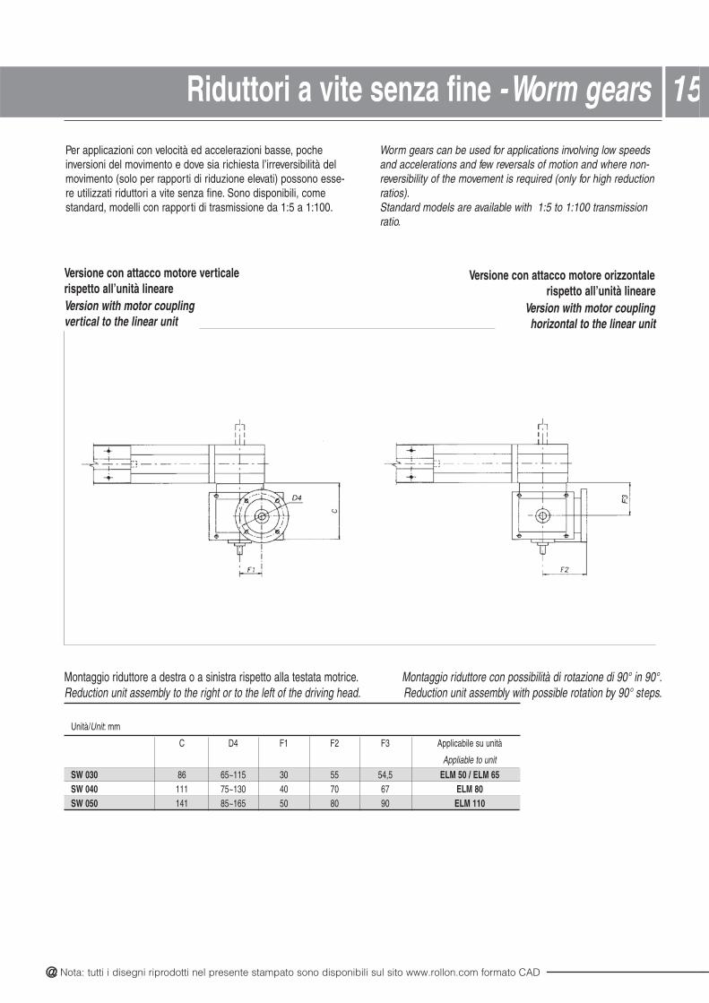
Per applicazioni con velocità ed accelerazioni basse, pocheinversioni del movimento e dove sia richiesta l’irreversibilità delmovimento (solo per rapporti di riduzione elevati) possono esse-re utilizzati riduttori a vite senza fine. Sono disponibili, comestandard, modelli con rapporti di trasmissione da 1:5 a 1:100.
Worm gears can be used for applications involving low speedsand accelerations and few reversals of motion and where non-reversibility of the movement is required (only for high reductionratios).Standard models are available with 1:5 to 1:100 transmissionratio.
Unità/Unit: mm
C D4 F1 F2 F3 Applicabile su unità
Appliable to unit
SW 030 86 65~115 30 55 54,5 ELM 50 / ELM 65SW 040 111 75~130 40 70 67 ELM 80 SW 050 141 85~165 50 80 90 ELM 110
Montaggio riduttore a destra o a sinistra rispetto alla testata motrice. Montaggio riduttore con possibilità di rotazione di 90° in 90°.Reduction unit assembly to the right or to the left of the driving head. Reduction unit assembly with possible rotation by 90° steps.
Versione con attacco motore verticalerispetto all’unità lineareVersion with motor couplingvertical to the linear unit
Versione con attacco motore orizzontalerispetto all’unità lineare
Version with motor couplinghorizontal to the linear unit
15Riduttori a vite senza fine - Worm gears 1
@ All the drawings in this catalogue are available in CAD files on www.rollon.com
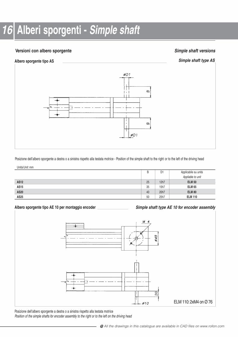
Versioni con albero sporgente Simple shaft versions
Posizione dell’albero sporgente a destra o a sinistra rispetto alla testata motrice - Position of the simple shaft to the right or to the left of the driving head
Posizione dell’albero sporgente a destra o a sinistra rispetto alla testata motricePosition of the simple shafts for encoder assembly to the right or to the left on the driving head
Albero sporgente tipo AS Simple shaft type AS
Unità/Unit: mmB D1 Applicabile su unità
Appliable to unit
AS12 25 12h7 ELM 50AS15 35 15h7 ELM 65
AS20 40 20h7 ELM 80AS25 50 25h7 ELM 110
Albero sporgente tipo AE 10 per montaggio encoder Simple shaft type AE 10 for encoder assembly
1616 Alberi sporgenti - Simple shaft
ELM 110: 2xM4 on Ø 76
@ Nota: tutti i disegni riprodotti nel presente stampato sono disponibili sul sito www.rollon.com formato CAD
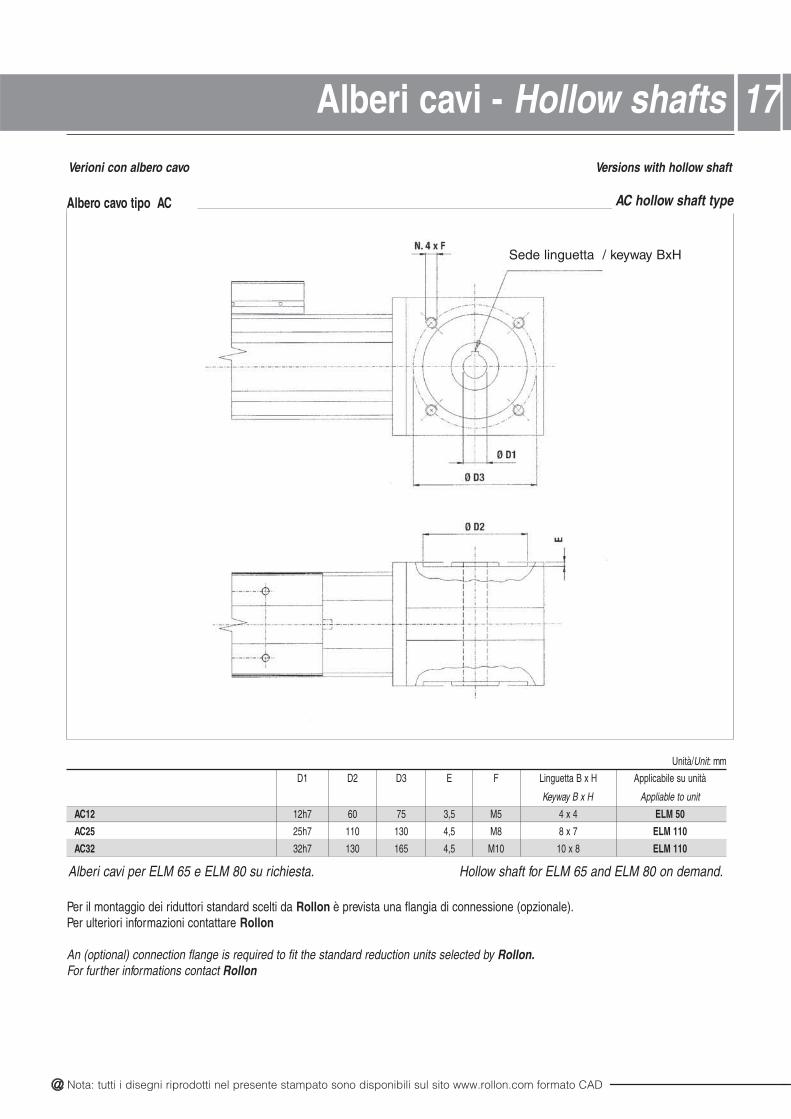
Verioni con albero cavo
Alberi cavi per ELM 65 e ELM 80 su richiesta. Hollow shaft for ELM 65 and ELM 80 on demand.
Versions with hollow shaft
Unità/Unit: mm
D1 D2 D3 E F Linguetta B x H Applicabile su unità
Keyway B x H Appliable to unit
AC12 12h7 60 75 3,5 M5 4 x 4 ELM 50
AC25 25h7 110 130 4,5 M8 8 x 7 ELM 110
AC32 32h7 130 165 4,5 M10 10 x 8 ELM 110
Albero cavo tipo AC AC hollow shaft type
Per il montaggio dei riduttori standard scelti da Rollon è prevista una flangia di connessione (opzionale).Per ulteriori informazioni contattare Rollon
An (optional) connection flange is required to fit the standard reduction units selected by Rollon.For further informations contact Rollon
17Alberi cavi - Hollow shafts
Sede linguetta / keyway BxH
@ All the drawings in this catalogue are available in CAD files on www.rollon.com
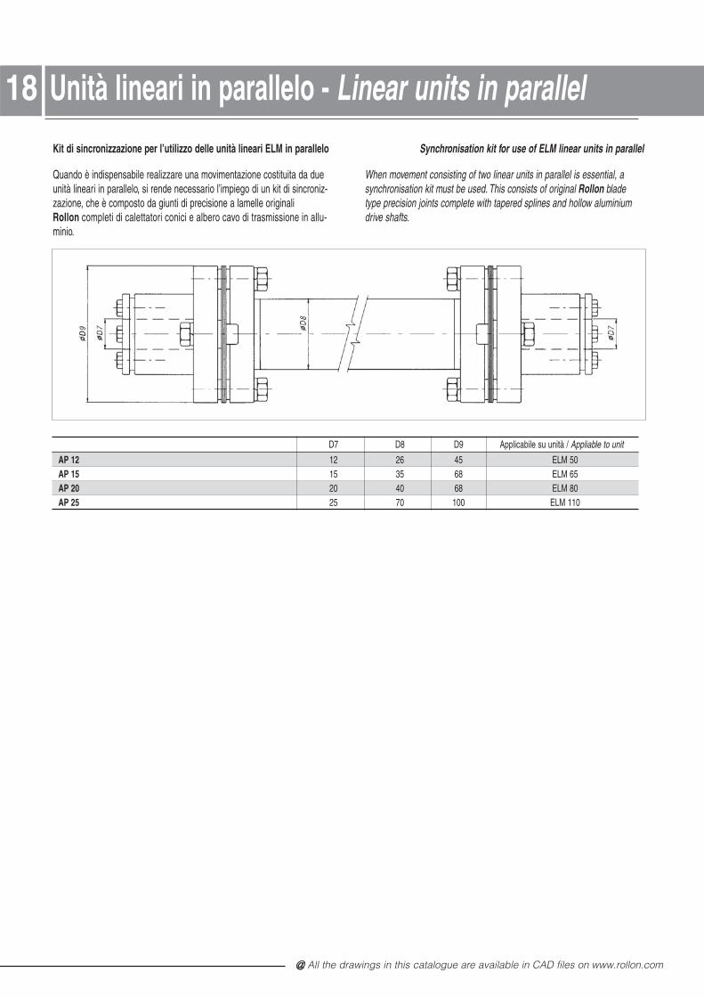
Kit di sincronizzazione per l’utilizzo delle unità lineari ELM in parallelo
Quando è indispensabile realizzare una movimentazione costituita da dueunità lineari in parallelo, si rende necessario l’impiego di un kit di sincroniz-zazione, che è composto da giunti di precisione a lamelle originaliRollon completi di calettatori conici e albero cavo di trasmissione in allu-minio.
Synchronisation kit for use of ELM linear units in parallel
When movement consisting of two linear units in parallel is essential, asynchronisation kit must be used. This consists of original Rollon bladetype precision joints complete with tapered splines and hollow aluminiumdrive shafts.
D7 D8 D9 Applicabile su unità / Appliable to unit
AP 12 12 26 45 ELM 50AP 15 15 35 68 ELM 65AP 20 20 40 68 ELM 80AP 25 25 70 100 ELM 110
1818 Unità lineari in parallelo - Linear units in parallel
@ Nota: tutti i disegni riprodotti nel presente stampato sono disponibili sul sito www.rollon.com formato CAD
Lubrificazione - Lubrication 19
Unità lineari con guide a ricircolo di sfere SP
Nelle versioni SP vengono montate guide a ricircolo di sfereesente da manutenzione.
I carrelli sono dotati di gabbie di ritenuta in plastica che evitano ilcontatto acciaio - acciaio tra corpi volventi adiacenti.La gabbia elimina, inoltre, lo strisciamento fra le sfere conconseguente riduzione dell’usura dovuta all’attrito.
Per rendere il sistema esente da manutenzione sui frontali deicarrelli a ricircolo di sfere sono stati installati dei serbatoi di lubri-ficante che rilasciano la giusta quantità di grasso nelle zone ovele sfere sopportano i carichi applicati. Questo sistema garantisceuna vita di funzionamento di circa 20.000 chilometri senza rilubri-ficazione. Solo in caso di elevate dinamiche del sistema e/o dielevati carichi applicati, contattare Rollon per le necessarie verifiche.
Unità lineari con guide a rotelle CI
Le unità lineari con guide a rotelle sono dotate di unsistema di lubrificazione continuativa. Quattro feltri, intri-si di grasso di adeguata viscosità con relativi serbatoi,garantiscono una durata di ca. 6000 km senza rilubrifi-cazione. Per un'eventuale lubrificazione per arrivare adurate superiori contattare Rollon .
SP linear units with ball bearing guides
In linear units type SP maintainance-free linear ball guides areused.
The ball bearing carriages of the SP versions are also fitted witha retention cage that eliminates "steel-steel" contact betweenadjacent revolving parts and prevents misalignment of these inthe circuits.
On the front plates of the linear blocks special lube-units aremounted which are continuously providing the necessary quan-tity of grease to the ball rows under load. This system guaranteesa service life of ca. 20.000 km without relubrication. If a longerservice life is required or in case of high dynamic or high loadedapplications please contact Rollon for further verification.
The lubrication reservoirs (pockets) fitted on the cages conside-rably increase re-lubrication frequency.
Linear units type CI with lancet arch bearing guides
Linear units with lancet arch bearing guides are equipped with along period lubrication system. Four grease impregnated feltscrapers, complete with grease reservoirs, guarantee a servicelife of ca. 6000 km without relubrication. If relubrication is requi-red to obtain a higher service life please contact Rollon .
@ All the drawings in this catalogue are available in CAD files on www.rollon.com
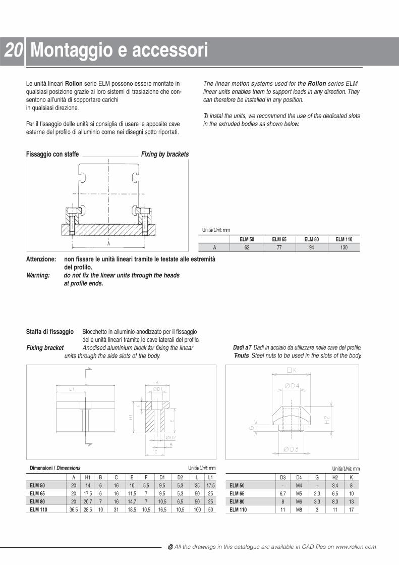
Dimensioni / Dimensions Unità/Unit: mm
A H1 B C E F D1 D2 L L1ELM 50 20 14 6 16 10 5,5 9,5 5,3 35 17,5ELM 65 20 17,5 6 16 11,5 7 9,5 5,3 50 25ELM 80 20 20,7 7 16 14,7 7 10,5 6,5 50 25ELM 110 36,5 28,5 10 31 18,5 10,5 16,5 10,5 100 50
2020
D3 D4 G H2 KELM 50 - M4 - 3,4 8ELM 65 6,7 M5 2,3 6,5 10ELM 80 8 M6 3,3 8,3 13ELM 110 11 M8 3 11 17
Le unità lineari Rollon serie ELM possono essere montate in qualsiasi posizione grazie ai loro sistemi di traslazione che con-sentono all’unità di sopportare carichi in qualsiasi direzione.
Per il fissaggio delle unità si consiglia di usare le apposite caveesterne del profilo di alluminio come nei disegni sotto riportati.
The linear motion systems used for the Rollon series ELM linear units enables them to support loads in any direction. Theycan therefore be installed in any position.
To instal the units, we recommend the use of the dedicated slotsin the extruded bodies as shown below.
Fissaggio con staffe Fixing by brackets
Unità/Unit: mm
ELM 50 ELM 65 ELM 80 ELM 110A 62 77 94 130
Attenzione: non fissare le unità lineari tramite le testate alle estremitàdel profilo.
Warning: do not fix the linear units through the headsat profile ends.
Staffa di fissaggio Blocchetto in alluminio anodizzato per il fissaggiodelle unità lineari tramite le cave laterali del profilo.
Fixing bracket Anodised aluminium block for fixing the linear units through the side slots of the body.
Dadi a T Dadi in acciaio da utilizzare nelle cave del profilo.T-nuts Steel nuts to be used in the slots of the body.
A
Unità/Unit: mm
Montaggio e accessori
@ Nota: tutti i disegni riprodotti nel presente stampato sono disponibili sul sito www.rollon.com formato CAD
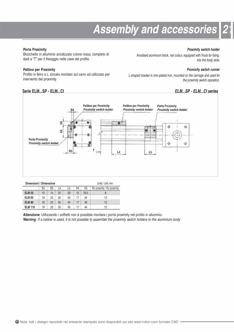
Dimensioni / Dimensions Unità / Unit: mmB4 B5 L4 L5 H4 H5 Per proximity / For proximity
ELM 50 10 14 25 29 12 29,5 8ELM 65 18 20 50 40 17 34 12ELM 80 18 20 50 40 17 39 12ELM 110 18 20 50 40 17 44 12
21Assembly and accessoriesPorta ProximityBlocchetto in alluminio anodizzato colore rosso, completo didadi a “T” per il fissaggio nelle cave del profilo.
Pattino per Proximity Profilo in ferro a L zincato montato sul carro ed utilizzato perintervento del proximity.
Serie ELM...SP - ELM...CI ELM...SP - ELM...CI series
Attenzione: Utilizzando i soffietti non è possibile montare i porta proximity nel profilo in alluminio.Warning: If a bellow is used, it is not possible to assemble the proximity switch holders to the aluminium body.
Proximity switch holderAnodised aluminium block, red colour, equipped with T-nuts for fixing
into the body slots.
Promixity switch runnerL-shaped bracket in zinc-plated iron, mounted on the carriage and used for
the proximity switch operation.
@ All the drawings in this catalogue are available in CAD files on www.rollon.com
Dimensioni / Dimensions Unità / Unit: mm
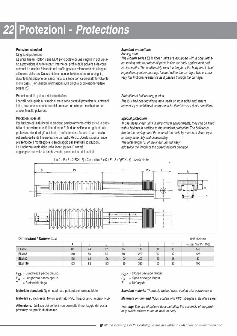
Unità: mmA B C D E F T PCH per / for PA= 1000ELM 50 83 44 67 65 110 80 15 140ELM 65 110 50 85 80 220 95 17 128ELM 80 135 62 106 100 300 120 25 80ELM 110 153 82 133 135 380 160 20 100
PCH = Lunghezza pacco chiusoPA = Lunghezza pacco apertoT = Profondità piega
Materiale standard: Nylon spalmato poliuretano termosaldato
Materiali su richiesta: Nylon spalmato PVC, fibra di vetro, acciaio INOX
Attenzione: L’utilizzo dei soffietti non permette il montaggio dei portaproximity nel profilo di alluminio.
PCH = Closed package lengthPA = Open package lengthT = fold depth
Standard material Thermally welded nylon coated with polyurethane
Materials on demand Nylon coated with PVC, fiberglass, stainless steel
Warning: The use of bellows does not allow the assembly of the proxi-mity switch holders to the aluminium body.
L = D + E + F + 2(PCH +5) + Corsa utile / L = D + E + F + 2(PCH + 5) + Useful stroke
2222 Protezioni - ProtectionsProtezioni standardCinghia di protezioneLe unità lineari Rollon serie ELM sono dotate di una cinghia in poliureta- no a protezione di tutte le parti interne del profilo dalla polvere e da corpiestranei. La cinghia è inserita nel profilo grazie a microcuscinetti alloggiatiall’interno del carro. Questo sistema consente di mantenere la cinghia,durante la traslazione del carro, nella sua sede con valori di attrito volventemolto bassi. (Per ulteriori informazioni sulla cinghia di protezione vederepagina 23).
Protezione delle guide a ricircolo di sfereI carrelli delle guide a ricircolo di sfere sono dotati di protezioni su entrambi ilati e, dove necessario, è possibile montare un ulteriore raschiatore perambienti molto polverosi.
Protezioni specialiPer l’utilizzo di unità lineari in ambienti particolarmente critici esiste la possi-bilità di corredare le unità lineari serie ELM di un soffietto in aggiunta allaprotezione standard già esistente. Il soffietto viene fissato al carro e alleestremità dell’unità lineare tramite un nastro Velcro. Questo sistema rendepiù semplice il montaggio e lo smontaggio per eventuali sostituzioni.La lunghezza totale delle unità lineari (quota L) varierà:aggiungere due volte la lunghezza del pacco chiuso del soffietto.
Standard protectionsSealing stripThe Rollon series ELM linear units are equipped with a polyuretha- ne sealing strip to protect all parts inside the body against dust andforeign matter. The sealing strip runs the length of the body and is keptin position by micro-bearings located within the carriage. This ensuresvery low frictional resistance as it passes through the carriage.
Protection of ball bearing guidesThe four ball bearing blocks have seals on both sides and, wherenecessary, an additional scraper can be fitted for very dusty conditions.
Special protectionTo use these linear units in very critical environments, they can be fittedwith a bellows in addition to the standard protection. The bellows isfixedto the carriage and the ends of the body by means of Velcro tapefor easy assembly and disassembly.The total length (L) of the linear unit will vary:add twice the length of the closed bellows package.
C
@ Nota: tutti i disegni riprodotti nel presente stampato sono disponibili sul sito www.rollon.com formato CAD
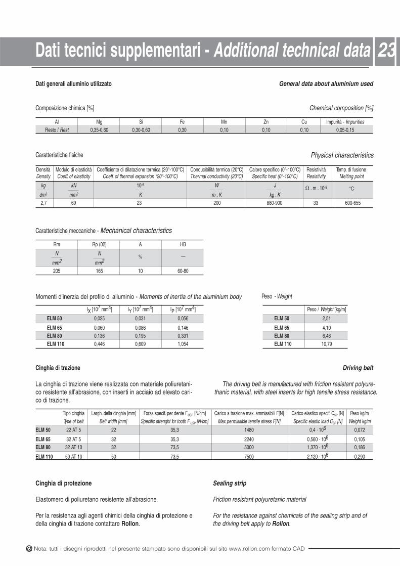
Densità Modulo di elasticità Coefficiente di dilatazione termica (20°-100°C) Conducibilità termica (20°C) Calore specifico (0°-100°C) Resistività Temp. di fusioneDensity Coeff. of elasticity Coeff. of thermal expansion (20°-100°C) Thermal conductivity (20°C) Specific heat (0°-100°C) Resistivity Melting point
kg kN 10-6 JW . m . 10-9 °Cdm3 mm2 K. gkK. mK
556-00633009-08800232967,2
Al Mg Si Fe Mn Zn Cu Impurità - ImpuritiesResto / Rest 0,35-0,60 0,30-0,60 0,30 0,10 0,10 0,10 0,05-0,15
Rm Rp (02) A HB
N N% —
mm2 mm2
205 165 10 60-80
IX [107 mm4] IY [107 mm4] IP [107 mm4]
ELM 50 0,025 0,031 0,056
ELM 65 0,060 0,086 0,146ELM 80 0,136 0,195 0,331ELM 110 0,446 0,609 1,054
Tipo cinghia Largh. della cinghia [mm] Forza specif. per dente FUSP [N/cm] Carico a trazione max. ammissibili F[N] Carico elastico specif. CSP [N] Peso kg/mType of belt Belt width [mm] Specific strenght for tooth F USP [N/cm] Max permissible tensile stress F[N] Specific elastic load CSP [N] Weight kg/m
ELM 50 4,008413,5322 5 TA22 . 106 0,072
ELM 65 065,004223,53235 TA 23 . 106 0,105ELM 80 073,100055,372301 TA 23 . 106 0,186
ELM 110 021,200575,370501 TA 05 . 106 0,290
Peso / Weight [kg/m]
ELM 50 2,51
ELM 65 4,10ELM 80 6,46ELM 110 10,79
Dati generali alluminio utilizzato
Composizione chimica [%]
General data about aluminium used
Chemical composition [%]
Caratteristiche fisiche Physical characteristics
Caratteristiche meccaniche - Mechanical characteristics
Momenti d’inerzia del profilo di alluminio - Moments of inertia of the aluminium body
Cinghia di trazione
La cinghia di trazione viene realizzata con materiale poliuretani-co resistente all’abrasione, con inserti in acciaio ad elevato cari-co di trazione.
Driving belt
The driving belt is manufactured with friction resistant polyure-thanic material, with steel inserts for high tensile stress resistance.
Cinghia di protezione
Elastomero di poliuretano resistente all’abrasione.
Per la resistenza agli agenti chimici della cinghia di protezione edella cinghia di trazione contattare Rollon.
Sealing strip
Friction resistant polyuretanic material
For the resistance against chemicals of the sealing strip and ofthe driving belt apply to Rollon.
23Dati tecnici supplementari - Additional technical data
Peso - Weight
@ All the drawings in this catalogue are available in CAD files on www.rollon.com
Unità multiasse2424
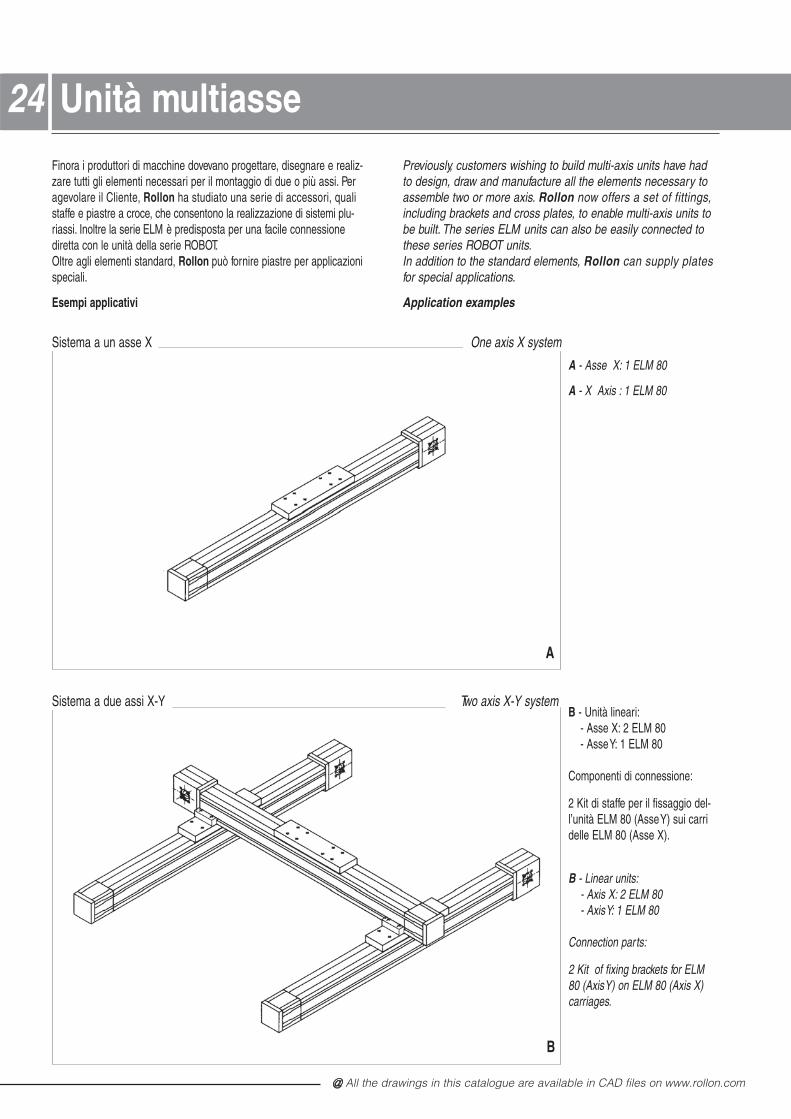
Sistema a un asse X One axis X system
Sistema a due assi X-Y Two axis X-Y system
Finora i produttori di macchine dovevano progettare, disegnare e realiz-zare tutti gli elementi necessari per il montaggio di due o più assi. Peragevolare il Cliente, Rollon ha studiato una serie di accessori, quali staffe e piastre a croce, che consentono la realizzazione di sistemi plu-riassi. Inoltre la serie ELM è predisposta per una facile connessionediretta con le unità della serie ROBOT.Oltre agli elementi standard, Rollon può fornire piastre per applicazioni speciali.
Esempi applicativi
Previously, customers wishing to build multi-axis units have hadto design, draw and manufacture all the elements necessary toassemble two or more axis. Rollon now offers a set of fittings,including brackets and cross plates, to enable multi-axis units tobe built. The series ELM units can also be easily connected tothese series ROBOT units.In addition to the standard elements, Rollon can supply plates for special applications.
Application examples
A - Asse X: 1 ELM 80
A - X Axis : 1 ELM 80
B - Unità lineari:- Asse X: 2 ELM 80 - Asse Y: 1 ELM 80
Componenti di connessione:
2 Kit di staffe per il fissaggio del-l’unità ELM 80 (Asse Y) sui carri delle ELM 80 (Asse X).
B - Linear units:- Axis X: 2 ELM 80 - Axis Y: 1 ELM 80
Connection parts:
2 Kit of fixing brackets for ELM80 (Axis Y) on ELM 80 (Axis X)carriages.
A
B
@ Nota: tutti i disegni riprodotti nel presente stampato sono disponibili sul sito www.rollon.com formato CAD
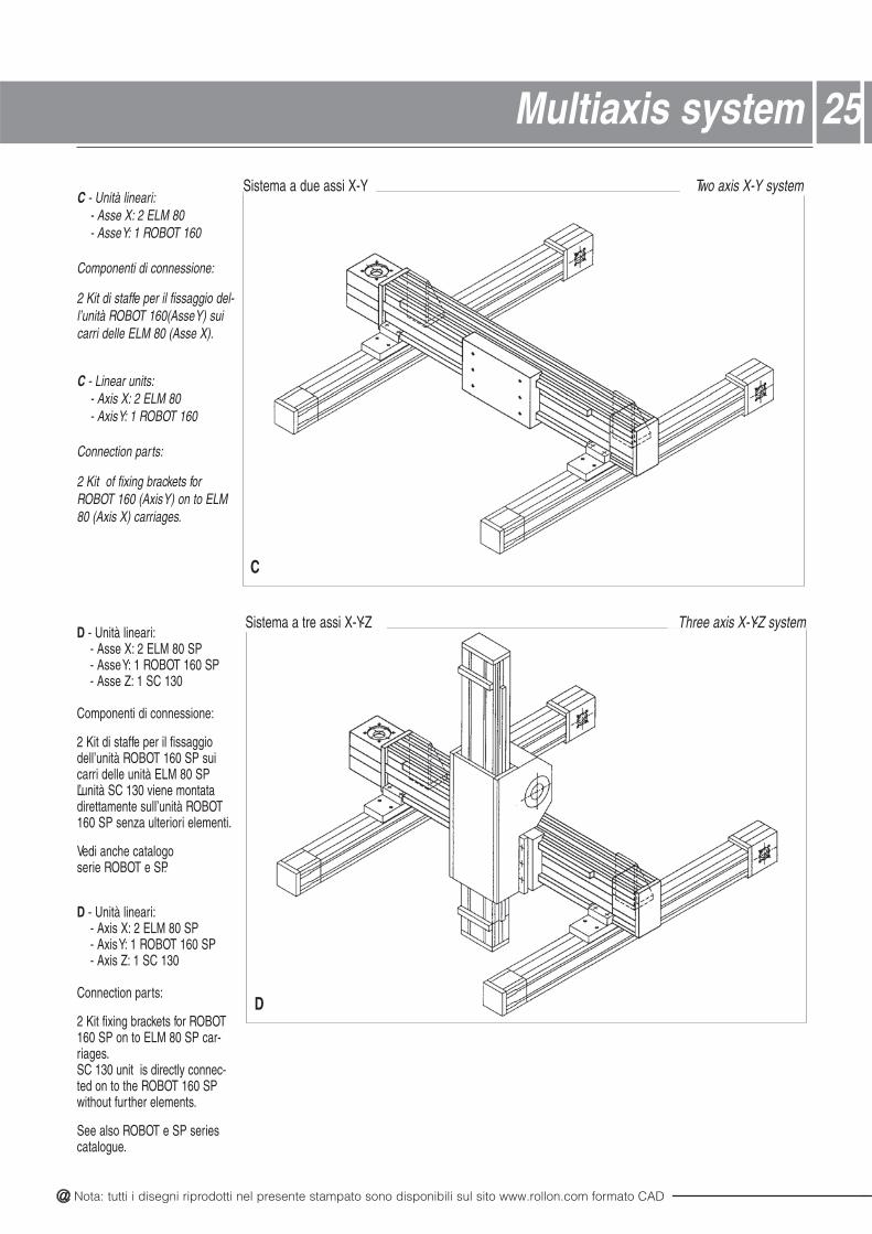
Two axis X-Y systemC - Unità lineari:
- Asse X: 2 ELM 80 - Asse Y: 1 ROBOT 160
Componenti di connessione:
2 Kit di staffe per il fissaggio del-l’unità ROBOT 160(Asse Y) suicarri delle ELM 80 (Asse X).
C - Linear units:- Axis X: 2 ELM 80 - Axis Y: 1 ROBOT 160
Connection parts:
2 Kit of fixing brackets forROBOT 160 (Axis Y) on to ELM80 (Axis X) carriages.
D - Unità lineari:- Asse X: 2 ELM 80 SP- Asse Y: 1 ROBOT 160 SP- Asse Z: 1 SC 130
Componenti di connessione:
2 Kit di staffe per il fissaggiodell’unità ROBOT 160 SP suicarri delle unità ELM 80 SPL’unità SC 130 viene montatadirettamente sull’unità ROBOT160 SP senza ulteriori elementi.
Vedi anche catalogo serie ROBOT e SP.
D - Unità lineari:- Axis X: 2 ELM 80 SP- Axis Y: 1 ROBOT 160 SP- Axis Z: 1 SC 130
Connection parts:
2 Kit fixing brackets for ROBOT160 SP on to ELM 80 SP car-riages.SC 130 unit is directly connec-ted on to the ROBOT 160 SPwithout further elements.
See also ROBOT e SP seriescatalogue.
25Multiaxis system
C
D
Sistema a due assi X-Y
Sistema a tre assi X-Y-Z Three axis X-Y-Z system
@ All the drawings in this catalogue are available in CAD files on www.rollon.com
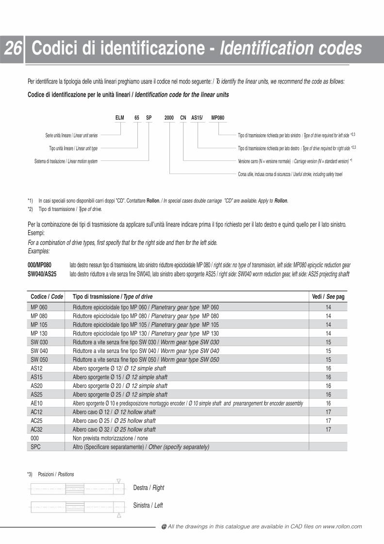
Codice / Code Tipo di trasmissione / Type of drive Vedi / See pag
MP 060 Riduttore epicicloidale tipo MP 060 / Planetrary gear type 41060 PMMP 080 Riduttore epicicloidale tipo MP 080 / Planetrary gear type 41080 PMMP 105 Riduttore epicicloidale tipo MP 105 / Planetrary gear type 41501 PMMP 130 Riduttore epicicloidale tipo MP 130 / Planetrary gear type 41031 PMSW 030 Riduttore a vite senza fine tipo SW 030 / Worm gear type SW 030 15SW 040 Riduttore a vite senza fine tipo SW 040 / Worm gear type SW 040 15SW 050 Riduttore a vite senza fine tipo SW 050 / Worm gear type SW 050 15AS12 Albero sporgente Ø 12/ Ø 12 simple shaft 16AS15 Albero sporgente Ø 15 / Ø 12 simple shaft 16AS20 Albero sporgente Ø 20 / Ø 12 simple shaft 16AS25 Albero sporgente Ø 25 / Ø 12 simple shaft 16AE10 Albero sporgente Ø 10 e predisposizione montaggio encoder / Ø 10 simple shaft and prearrangement for encoder assembly 16AC12 Albero cavo Ø 12 / Ø 12 hollow shaft 17AC25 Albero cavo Ø 25 / Ø 25 hollow shaft 17AC32 Albero cavo Ø 32 / Ø 25 hollow shaft 17000 Non prevista motorizzazione / noneSPC Altro (Specificare separatamente) / Other (specify separately)
Per identificare la tipologia delle unità lineari preghiamo usare il codice nel modo seguente: / To identify the linear units, we recommend the code as follows:
Codice di identificazione per le unità lineari / Identification code for the linear units
ELM 65 SP 2000 CN AS15/ MP080
Serie unità lineare / Linear unit series Tipo di trasmissione richiesta per lato sinistro / Type of drive required for left side *2,3
Tipo unità lineare / Linear unit type Tipo di trasmissione richiesta per lato destro / Type of drive required for right side *2,3
Sistema di traslazione / Linear motion system Versione carro (N = versione normale) / Carriage version (N = standard version) *1
Corsa utile, inclusa corsa di sicurezza / Useful stroke, including safety travel
*1) In casi speciali sono disponibili carri doppi ”CD”. Contattare Rollon. / In special cases double carriage ”CD” are available. Apply to Rollon.*2) Tipo di trasmissione / Type of drive.
Per la combinazione dei tipi di trasmissione da applicare sull’unità lineare indicare prima il tipo richiesto per il lato destro e quindi quello per il lato sinistro.Esempi:For a combination of drive types, first specify that for the right side and then for the left side.Examples:
000/MP080 lato destro nessun tipo di trasmissione, lato sinistro riduttore epicicloidale MP 080 / right side: no type of transmission, left side: MP080 epicyclic reduction gearSW040/AS25 lato destro riduttore a vite senza fine SW040, lato sinistro albero sporgente AS25 / right side: SW040 worm reduction gear, left side: AS25 projecting shaft
*3) Posizioni / Positions
Destra / Right
Sinistra / Left
2626 Codici di identificazione - Identification codes
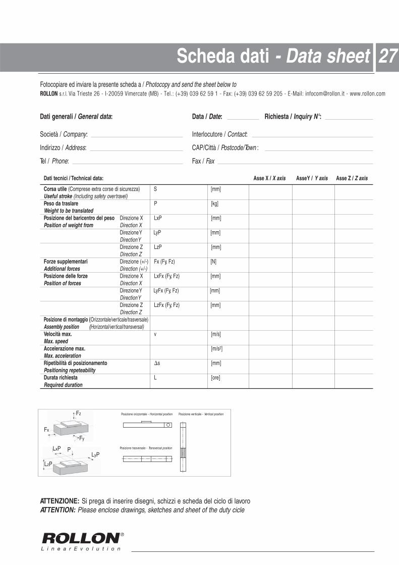
Scheda dati - Data sheet 27
Dati generali / General data / ataD: Date: Richiesta / Inquiry N°:
Società / Company / erotucolretnI: Contact:
Indirizzo / Address / àttiC/PAC: Postcode/Town :
Tel / Phone / xaF: Fax
/ X essA:atad lacinhceT / icincet itaD X axis Asse Y / Y axis Asse Z / Z axis
Corsa utile (Comprese extra corse di sicurezza) S [mm]Useful stroke (Including safety overtravel)Peso da traslare P [kg]Weight to be translatedPosizione del baricentro del peso Direzione X LxP [mm]Position of weight from Direction X
Direzione Y LyP [mm]Direction YDirezione Z LzP [mm]Direction Z
Forze supplementari Direzione (+/-) Fx (Fy, Fz) [N]Additional forces Direction (+/-)Posizione delle forze Direzione X LxFx (Fy, Fz) [mm]Position of forces Direction X
Direzione Y LyFx (Fy, Fz) [mm]Direction YDirezione Z LzFx (Fy, Fz) [mm]Direction Z
Posizione di montaggio (Orizzontale/verticale/trasversale)Assembly position (Horizontal/vertical/transversal)Velocità max. ]s/m[vMax. speedAccelerazione max. [m/s2]Max. accelerationRipetibilità di posizionamento s [mm]Positioning repeteabilityDurata richiesta ]ero[LRequired duration
ATTENZIONE: Si prega di inserire disegni, schizzi e scheda del ciclo di lavoroATTENTION: Please enclose drawings, sketches and sheet of the duty cicle
LxP
LzP
LyPP
Fz
Fy
Fx
Posizione orizzontale - Horizontal position Posizione verticale - Vertical position
Posizione trasversale - Transversal position
Fotocopiare ed inviare la presente scheda a / Photocopy and send the sheet below toROLLON s.r.l. Via Trieste 26 - I-20059 Vimercate (MB) - Tel.: (+39) 039 62 59 1 - Fax: (+39) 039 62 59 205 - E-Mail: [email protected] - www.rollon.com

RL_ELM_IT-UK_01/12 INTERNATIONALSalvo errori e variazioni. Testi e illustrazioni possono essere utilizzati solo previa autorizzazione da parte nostra. Changes and errors excepted. The text and images may be used only with our permission.
Gli indirizzi aggiornati dei nostri partner commerciali sitrovano all‘indirizzo www.rollon.comAll addresses of our global sales partners can alsobe found in the internet at www.rollon.com
Italy
ROLLON S.r.l.
Via Trieste 26
Fax: (+39) 039 62 59 205
E-Mail: [email protected]
www.rollon.it
I-20871 Vimercate (MB)
Phone: (+39) 039 62 59 1
Germ
any
ROLLON GmbH
Bonner Straße 317-319
D-40589 Düsseldorf
Phone: +49 (0) 211 95 747 0
Fax: +49 (0) 211 95 747 100
E-Mail: [email protected]
www.rollon.de
Fran
ce
ROLLON S.A.R.L.
Les Jardins d‘Eole, 2 allée des Séquoias
F-69760 Limonest
Phone: (+33) (0)4 74 71 93 30
Fax: (+33) (0)4 74 71 95 31
E-Mail: [email protected]
www.rollon.fr
USA
ROLLON Corporation
101 Bilby Road. Suite B
Hackettstown, NJ 07840
Phone: +1 (973) 300-5492
Fax: +1 (908) 852-2714
E-Mail: [email protected]
www.rolloncorp.com
Ringbaan Zuid 8
NL-6905 DB Zevenaar
Phone: (+31) 316 581 999
Fax: (+31) 316 341 236
E-Mail: [email protected]
www.rollon.nlNeth
erla
nds
ROLLON B.V.


![HOME []€¦ · Web viewMoto parabolico. Moto circolare uniforme. Moto armonico. Piccole oscillazioni del pen- dolo. Forza centripeta e elastica come cause dei moti stu- diati.](https://static.fdocumenti.com/doc/165x107/5fde02733b23d773133f4ffd/home-web-view-moto-parabolico-moto-circolare-uniforme-moto-armonico-piccole.jpg)