ZLJ14 RICAMBI ORIGINALI ORIGINAL SPARE PARTS · 2-3P Selettore a chiave e/o pulsante di apertura...
28
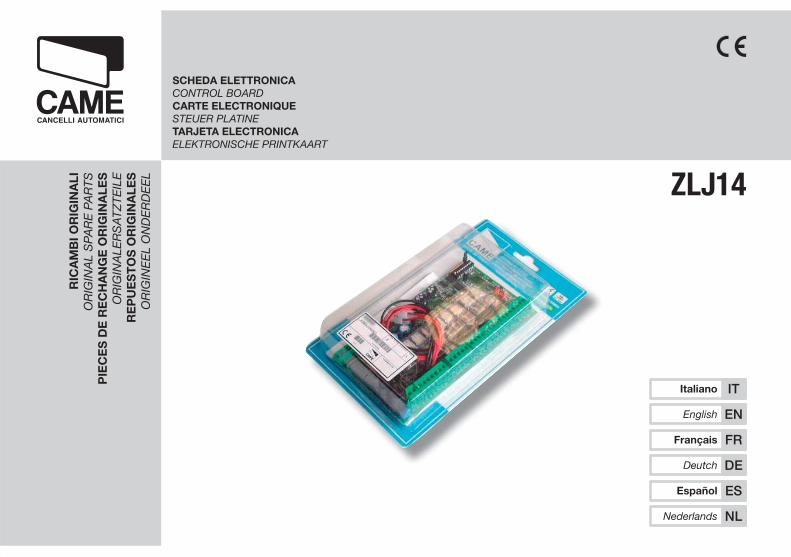
RICAMBI ORIGINALI ORIGINAL SPARE PARTS PIECES DE RECHANGE ORIGINALES ORIGINALERSATZTEILE REPUESTOS ORIGINALES ORIGINEEL ONDERDEEL SCHEDA ELETTRONICA CONTROL BOARD CARTE ELECTRONIQUE STEUER PLATINE TARJETA ELECTRONICA ELEKTRONISCHE PRINTKAART Nederlands NL Español ES Deutch DE Français FR English EN Italiano IT ZLJ14
Transcript of ZLJ14 RICAMBI ORIGINALI ORIGINAL SPARE PARTS · 2-3P Selettore a chiave e/o pulsante di apertura...
RIC
AM
BI O
RIG
INA
LIO
RIG
INA
L S
PAR
E P
AR
TSP
IEC
ES
DE
RE
CH
AN
GE
OR
IGIN
ALE
SO
RIG
INA
LER
SA
TZTE
ILE
RE
PU
ES
TO
S O
RIG
INA
LES
OR
IGIN
EE
L O
ND
ER
DE
EL
SCHEDA ELETTRONICACONTROL BOARDCARTE ELECTRONIQUESTEUER PLATINETARJETA ELECTRONICAELEKTRONISCHE PRINTKAART
Nederlands NL
Español ES
Deutch DE
Français FR
English EN
Italiano IT
ZLJ14

120V=3,15A-F
230V=1,6A-F
L N
24 12 0L1T L2T THERMAL
+ E - M N ENC B1 B2 2 FA FC S1 GND10 11 TS E E3 ES 1 2 3 3P 4 5 7 CX CY CZ
ZLJ1
4A
ITALIA
NO
Pag
. 3
-
Cod
ice
man
ual
e: 3
19
LR
35
31
9LR
35
ver
. 1
.01
.0 0
9/2
00
9 ©
CA
ME
cance
lli a
utom
atic
i s.p
.a.
I dati e le informazioni indicate in questo manuale sono da ritenersi suscettibili di modifica in qualsiasi momento e senza obbligo di preavviso da parte di CAME cancelli automatici s.p.a.
B1 B2 2 FA FC S1 GND
CANCELLI AUTOMATICI
R700
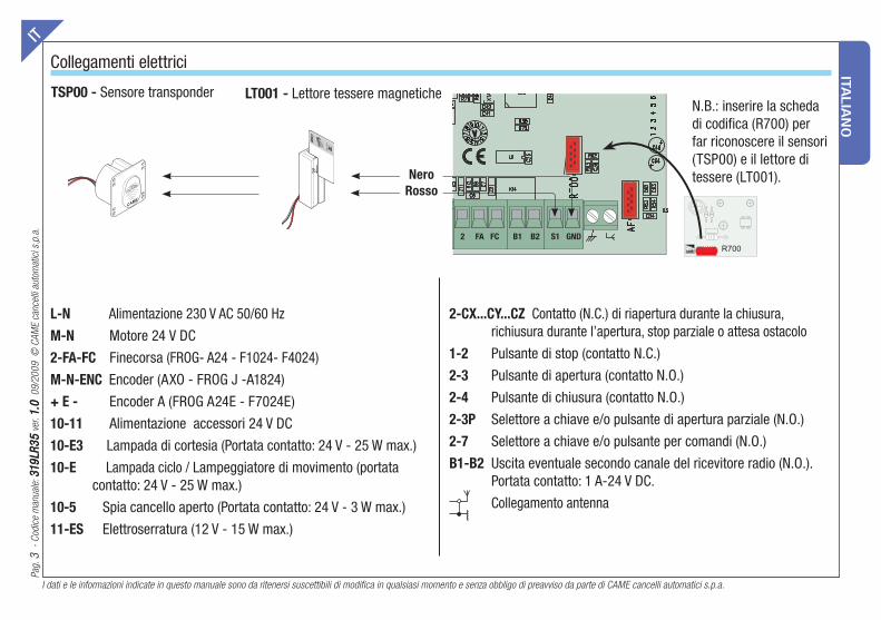
Collegamenti elettriciIT
L-N Alimentazione 230 V AC 50/60 Hz
M-N Motore 24 V DC
2-FA-FC Finecorsa (FROG- A24 - F1024- F4024)
M-N-ENC Encoder (AXO - FROG J -A1824)
+ E - Encoder A (FROG A24E - F7024E)
10-11 Alimentazione accessori 24 V DC
10-E3 Lampada di cortesia (Portata contatto: 24 V - 25 W max.)
10-E Lampada ciclo / Lampeggiatore di movimento (portata contatto: 24 V - 25 W max.)
10-5 Spia cancello aperto (Portata contatto: 24 V - 3 W max.)
11-ES Elettroserratura (12 V - 15 W max.)
2-CX...CY...CZ Contatto (N.C.) di riapertura durante la chiusura, richiusura durante l’apertura, stop parziale o attesa ostacolo
1-2 Pulsante di stop (contatto N.C.)
2-3 Pulsante di apertura (contatto N.O.)
2-4 Pulsante di chiusura (contatto N.O.)
2-3P Selettore a chiave e/o pulsante di apertura parziale (N.O.)
2-7 Selettore a chiave e/o pulsante per comandi (N.O.)
B1-B2 Uscita eventuale secondo canale del ricevitore radio (N.O.). Portata contatto: 1 A-24 V DC.
Collegamento antenna
TSP00 - Sensore transponder N.B.: inserire la scheda di codifica (R700) per far riconoscere il sensori (TSP00) e il lettore di tessere (LT001).
LT001 - Lettore tessere magnetiche
CAME
ACC
ESS CO
NTR
OL
Nero
Rosso
ITA
LIA
NO
I dati e le informazioni indicate in questo manuale sono da ritenersi suscettibili di modifica in qualsiasi momento e senza obbligo di preavviso da parte di CAME cancelli automatici s.p.a.
Pag
. 4
-
Cod
ice
man
ual
e: 3
19
LR
35
31
9LR
35
ver
. 1
.01
.0 0
9/2
00
9 ©
CA
ME
cance
lli a
utom
atic
i s.p
.a.
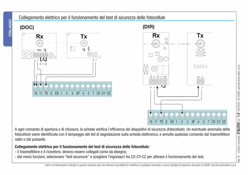
A ogni comando di apertura o di chiusura, la scheda verifi ca l’effi cienza dei dispositivi di sicurezza (fotocellule). Un eventuale anomalia delle fotocellule viene identifi cata con il lampeggio del led di segnalazione sulla scheda elettronica, e annulla qualsiasi comando dal trasmettitore radio o dal pulsante.
Collegamento elettrico per il funzionamento del test di sicurezza delle fotocellule:
- il trasmettitore e il ricevitore, devono essere collegati come da disegno;- dal menù funzioni, selezionare “test sicurezze” e scegliere l’ingresso/i tra CX-CY-CZ per attivare il funzionamento del test.
Collegamento elettrico per il funzionamento del test di sicurezza delle fotocellule
(DOC) (DIR)
ITALIA
NO
Pag
. 5
-
Cod
ice
man
ual
e: 3
19
LR
35
31
9LR
35
ver
. 1
.01
.0 0
9/2
00
9 ©
CA
ME
cance
lli a
utom
atic
i s.p
.a.
I dati e le informazioni indicate in questo manuale sono da ritenersi suscettibili di modifica in qualsiasi momento e senza obbligo di preavviso da parte di CAME cancelli automatici s.p.a.
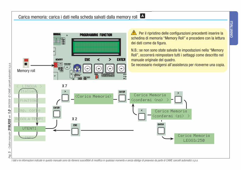
THERMAL Per il ripristino delle confi gurazioni precedenti inserire la schedina di memoria “Memory Roll” e procedere con la lettura dei dati come da fi gura.
N.B.: se non sono state salvate le impostazioni nella “Memory Roll”, occorrerà reimpostare tutti i settaggi come descritto nel manuale originale del quadro.Se necessario rivolgersi all’assistenza per riceverne una copia.
Carica memoria: carica i dati nella scheda salvati dalla memory roll
X 2
Carica Memoria
<confermi (no) >
Carica Memoria
<confermi (si) >
<Carica Memoria>
Carica Memoria
LEGGI:250
< LINGUA >
Italianono
FUNZIONII
REGOLA TEMPIEGOLA TEM
UTENTI
INFOINFO
X 7
ll A
Memory roll
Imp. corsaImp. cors

ITA
LIA
NO
I dati e le informazioni indicate in questo manuale sono da ritenersi suscettibili di modifica in qualsiasi momento e senza obbligo di preavviso da parte di CAME cancelli automatici s.p.a.
Pag
. 6
-
Cod
ice
man
ual
e: 3
19
LR
35
31
9LR
35
ver
. 1
.01
.0 0
9/2
00
9 ©
CA
ME
cance
lli a
utom
atic
i s.p
.a.
CAME Cancelli Automatici S.p.A.via Martiri della Libertà, 1531030 Dosson di Casier - Treviso - ITALYtel (+39) 0422 4940 - fax (+39) 0422 4941internet: www.came.it - e-mail: [email protected]
Dichiara sotto la propria responsabilità, che i seguenti prodotti per l’automazione di cancelli e porte da garage, così denominati:
… sono conformi ai requisiti essenziali ed alle disposizioni pertinenti, stabilite dalle seguenti Direttive e alle parti applicabili delle Normative di riferimento in seguito elencate.
2006/95/CE DIRETTIVA BASSA TENSIONE
2004/108/CE DIRETTIVA COMPATIBILITÀ ELETTROMAGNETICA
EN 60335-1 EN 61000-6-2 EN 60335-2-103 EN 61000-6-3 EN 13241-1
DICHIARAZIONE CE DI CONFORMITÀAi sensi della Direttiva Bassa Tensione
L’AMMINISTRATORE DELEGATOGianni Michielan
ZLJ14
Dismissione e smaltimento
Codice di riferimento per richiedere una copia conforme all’originale: DDF L IT Z002f
AVVERTENZA IMPORTANTE!È vietato mettere in servizio il/i prodotto/i, oggetto della presente
dichiarazione, prima del completamento e/o incorporamento, in totale conformità alle disposizioni della Direttiva Bassa Tensione 2006/95/CE
I nostri prodotti sono realizzati con materiali diversi. La maggior parte di essi (alluminio, plastica, ferro, cavi elettrici) è assimilabile ai rifi uti solidi e urbani. Possono essere riciclati attraverso la raccolta e lo smaltimento differenziato nei centri autorizzati.
Altri componenti (schede elettroniche, batterie dei transmettitori etc.) possono invece contenere sostanze inquinanti.
Vanno quindi rimossi e consegnati a ditte autorizzate al recupero e allo smaltimento degli stessi.

The data and information reported in this installation manual are susceptible to change at any time and without obligation on CAME cancelli automatici s.p.a. to notify users.
Pag
. 7
-
Man
ual
cod
e: 3
19
LR
35
31
9LR
35
ver
. 1
.01
.0 0
9/2
00
9 ©
CA
ME
cance
lli a
utom
atic
i s.p
.a.
EN
GLIS
H
B1 B2 2 FA FC S1 GND
Electrical connectionsENEN
L-N Power supply 230 V DC 50/60 Hz
M-N 24 V DC gearmotor
2-FA1-FC1 Endstop (FROG -A24 - F1024 - F4024)
M-N-ENC 24 V DC gearmotor (AXO-FROG J-A1824)
+ E - Encoder (FROG A24E-F7024E)
10-11 Terminals for powering 24 V DC accessories
10-E3 Courtesy lamp (Contact output: 24 V - 25 W max.)
10-E Cycle lamp / Flashing light (socket rating: 24 V - 25 W max.)
10-5 Open gate indicator-light (socket rating: 24 V - 3 W max.)
11-ES Electrolock connection (12 V - 15 W max)
2-CX..CY..CZ Re-open during closing (N.C.) socket, re-close during opening, partial stop or stand-by Obstacle
1-2 Stop button (N.C. contact)
2-3 Opening button (N.O. contact)
2-4 Closing button (N.O. contact)
2-3P Partial opening button (N.O.)
2-7 Keyswitch and/or commands button (N.O.)
B1-B2 Possible output of the radio receiver’s second channel (N.O.). Socket rating: 1 A - 24 V DC.
Antenna connection
TSP00 - Transponder sensorN.B.: insert the (R700) coding board to have the (TSP00) sensor or (LT001) card reader recognised.
LT001 - Magnetic card reader
CAME
ACC
ESS CO
NTR
OL
CANCELLI AUTOMATICI
R700
Black
Red
The data and information reported in this installation manual are susceptible to change at any time and without obligation on CAME cancelli automatici s.p.a. to notify users.
Pag
. 8
-
Man
ual
cod
e: 3
19
LR
35
31
9LR
35
ver
. 1
.01
.0 0
9/2
00
9 ©
CA
ME
cance
lli a
utom
atic
i s.p
.a.
EN
GLIS
H
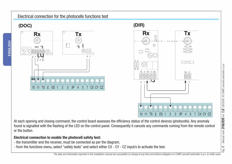
At each opening and closing command, the control board assesses the effi ciency status of the control devices (photocells). Any anomaly found is signalled with the fl ashing of the LED on the control panel. Consequently it cancels any commands coming from the remote control or the button.
Electrical connection to enable the photocell safety test:
- the transmitter and the receiver, must be connected as per the diagram;- from the functions menu, select “safety tests” and select either CX - CY - CZ input/s to activate the test.
Electrical connection for the photocells functions test
(DOC) (DIR)
The data and information reported in this installation manual are susceptible to change at any time and without obligation on CAME cancelli automatici s.p.a. to notify users.
Pag
. 9
-
Man
ual
cod
e: 3
19
LR
35
31
9LR
35
ver
. 1
.01
.0 0
9/2
00
9 ©
CA
ME
cance
lli a
utom
atic
i s.p
.a.
EN
GLIS
H
THERMAL
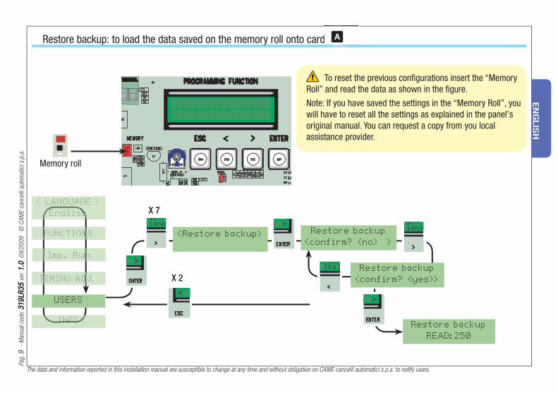
Restore backup: to load the data saved on the memory roll onto card
ngualiano
o
o
o
ngualiano
X 2
LinItal
Restore backup
<confirm? (no) >
Restore backup
<confirm? (yes)>
<Restore backup>
Restore backup
READ:250
X 7
dd A
To reset the previous confi gurations insert the “Memory Roll” and read the data as shown in the fi gure.
Note: If you have saved the settings in the “Memory Roll”, you will have to reset all the settings as explained in the panel’s original manual. You can request a copy from you local assistance provider.
Memory roll
FUNCTIONSFUNCTION
TIMING ADJ.TIMING AD
INFOINFO
Imp. Runn
< LANGUAGE >
Englishsh
USERS
The data and information reported in this installation manual are susceptible to change at any time and without obligation on CAME cancelli automatici s.p.a. to notify users.
Pag
. 1
01
0
- M
anual
cod
e: 3
19
LR
35
31
9LR
35
ver
. 1
.01
.0 0
9/2
00
9 ©
CA
ME
cance
lli a
utom
atic
i s.p
.a.
EN
GLIS
H
Disposal
CAME Cancelli Automatici S.p.A.via Martiri della Libertà, 1531030 Dosson di Casier - Treviso - ITALYtel (+39) 0422 4940 - fax (+39) 0422 4941internet: www.came.it - e-mail: [email protected]
Declares under its own responsibility that the equipments for automatic garage doors and gates listed below:
… comply with the National Law related to the following European Directives and to the applicable parts of the following Standards.
2006/95/EC LOW VOLTAGE DIRECTIVE
2004/108/EEC ELECTROMAGNETIC COMPATIBILITY DIRECTIVE
EN 60335-1 EN 61000-6-2 EN 60335-2-103 EN 61000-6-3 EN 13241-1
EC DECLARATION OF CONFORMITYPursuant to the Low Voltage Directive
THE MANAGING DIRECTORGianni Michielan
ZLJ14
Reference code to request a true copy of the original: DDF L EN Z002f
IMPORTANT WARNING!Do not use the equipment specifi ed here above, before completing the full installation. In full compliance to the Low Voltage Directive
2006/95/EC
This product, including the packaging, is made up of several types of materials that can be recycled.
Investigate the recycling or disposal systems of the product, complying with prevailing local legislation.
Some electronic components may contain polluting substances. Do not litter.
Pag
. 1111
-
Cod
e m
anuel
: 3
19
LR
35
31
9LR
35
ver
. 1
.01
.0 0
9/2
00
9 ©
CA
ME
cance
lli a
utom
atic
i s.p
.a.
Les données et les indications fournies dans ce manuel d’installation peuvent subir des modifications à tout moment sans avis préalable de la part de CAME cancelli automatici s.p.a.
FR
AN
ÇA
IS
B1 B2 2 FA FC S1 GND
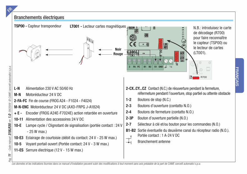
Branchements électriquesFR
L-N Alimentation 230 V AC 50/60 Hz
M-N Motoréducteur 24 V DC
2-FA-FC Fin de course (FROG A24 - F1024 - F4024)
M-N-ENC Motoréducteur 24 V DC (AXO-FRPG J-A1824)
+ E - Encoder (FROG A24E-F7024E) action retardée en ouverture
10-11 Alimentation des accessoires 24 V DC
10-E Lampe cycle / Clignotant de signalisation (portée contact : 24 V
- 25 W max.)
10-E3 Eclairage de courtoisie (débit du contact: 24 V - 25 W max.)
10-5 Voyant portail ouvert (Portée contact: 24 V - 3 W max.)
11-ES Serrure électrique (12 V - 15 W max.)
2-CX..CY...CZ Contact (N.C.) de réouverture pendant la fermeture, réfermeture pendant l’ouverture, stop partiel ou attente obstacle
1-2 Boutons de stop (N.C.)
2-3 Boutons d’ouverture (contatto N.O.)
2-4 Boutons de fermeture (contatto N.O.)
2-3P Bouton d’ouverture partielle (N.O.)
2-7 Sélecteur à clé et/ou bouton pour les commandes (N.O.)
B1-B2 Sortie éventuelle du deuxième canal du récepteur radio (N.O.). Portée contact : 1 A-24 V DC
Branchement antenne
N.B.: introduisez le carte de décodage (R700) pour faire reconnaître le capteur (TSP00) ou le lecteur de cartes (LT001).
TSP00 - Capteur transpondeur LT001 - Lecteur cartes magnétiques
CAME
ACC
ESS CO
NTR
OL
CANCELLI AUTOMATICI
R700
Noir
Rouge

Les données et les indications fournies dans ce manuel d’installation peuvent subir des modifications à tout moment sans avis préalable de la part de CAME cancelli automatici s.p.a.
Pag
. 1
21
2
- C
ode
man
uel
: 3
19
LR
35
31
9LR
35
ver
. 1
.01
.0 0
9/2
00
9 ©
CA
ME
cance
lli a
utom
atic
i s.p
.a.
FR
AN
ÇA
IS
A chaque commande d’ouverture ou de fermeture, la carte contrôle le fonctionnement des photocellules. Une anomalie éventuelle détectée sur les photocellules est signalée par le clignotement de la Led sur la carte électronique et elle annule toute commande de l’émetteur radio ou du bouton.
Connexion électrique pour le fonctionnement du test de contrôle de sécurité des photocellules:
- l’émetteur et le récepteur doivent être connectés comme sur le dessin ;- dans le menu fonctions sélectionnez ’’test de sécurité’’ et choisissez l’entrée/s entre CX-CY-CZ pour mettre en service le fonctionnement du test.
Connexion électrique pour le fonctionnement du test de contrôle de sécurité des photocellules
(DOC) (DIR)

Pag
. 1
31
3
- C
ode
man
uel
: 3
19
LR
35
31
9LR
35
ver
. 1
.01
.0 0
9/2
00
9 ©
CA
ME
cance
lli a
utom
atic
i s.p
.a.
Les données et les indications fournies dans ce manuel d’installation peuvent subir des modifications à tout moment sans avis préalable de la part de CAME cancelli automatici s.p.a.
FR
AN
ÇA
IS
THERMAL
Pour la restauration des configurations précédentes, introduisez la carte de mémoire “Memory Roll” et effectuez la lecture des données en procédant comme sur le dessin.
N.B.: Si les configurations n’ont pas été sauvegardées sur la liste de mémoire « Memory Roll », vous devez afficher de nouveau toutes les configurations comme il est indiqué sur le manuel d’utilisation de l’armoire de commande. Vous pouvez vous adresser directement au service après-vente pour en recevoir une copie si elle vous est nécessaire.
Chargement mémoire: elle charge dans la carte les données sauvegardées dans la liste de la mémoire
X 2
Charg.Memoire
<confirme?(non)>
Charg.Memoire
<confirme?(oui)>
<Charg.Memoire>
Charg.Memoire
LECTURE:250
< LANGUE >
FrancaisFrancais
USAGERSS
X 7
eee A
Memory roll
FONCTIONSFONCTION
REGLAGE DUREESEGLAGE DUR
INFOINFO
Config.Courseonfig.Cour

Les données et les indications fournies dans ce manuel d’installation peuvent subir des modifications à tout moment sans avis préalable de la part de CAME cancelli automatici s.p.a.
Pag
. 14
14
-
Cod
e m
anuel
: 3
19
LR
35
31
9LR
35
ver
. 1
.01
.0 0
9/2
00
9 ©
CA
ME
cance
lli a
utom
atic
i s.p
.a.
FR
AN
ÇA
IS
Recyclage et élimination
CAME Cancelli Automatici S.p.A.via Martiri della Libertà, 1531030 Dosson di Casier - Treviso - ITALYtel (+39) 0422 4940 - fax (+39) 0422 4941internet: www.came.it - e-mail: [email protected]
Déclare sous sa responsabilité, que les produits suivants pour l’automation de portails et portes de garage, ainsi dénommés:
... sont conformes aux conditions nécessaires et aux dispositions appropriées, fi xées par les Directives suivantes et aux articles applicables des Règlementations de référence indiqués ci-après.
2006/95/CE DIRECTIVE BASSE TENSION
2004/108/CEE DIRECTIVE COMPATIBILITÉ ELECTROMAGNETIQUE
EN 60335-1 EN 61000-6-2 EN 60335-2-103 EN 61000-6-3 EN 13241-1
DECLARATION CE DE CONFORMITEAux termes de la Directive Basse Tension
L’ADMINISTRATEUR DÉLÉGUÉGianni Michielan
ZLJ14
Code de référence pour demander une copie conforme à l’original: DDF L FR Z002f
AVIS IMPORTANT !Il est interdit de mettre en service les produits, objet de cette
déclaration, avant de les incorporer à l’installation et/ou de terminer le montage de cette dernière, conformément aux dispositions de la
Directive Basse Tension 2006/95/CE
Cet appareil, y compris l’emballage, est constitué de plusieurs types de matériaux pouvant être recyclés.
S’informer sur les systèmes de recyclage ou d’élimination de l’appareil en se conformant aux lois locales en vigueur.
Certains composants électroniques pourraient contenir des substances polluantes, ne pas les jeter n’importe où.
Sei
te 1
51
5
- H
andbuch
-Cod
e: 3
19
LR
35
31
9LR
35
ver
. 1
.01
.0 0
9/2
00
9 ©
CA
ME
cance
lli a
utom
atic
i s.p
.a.
Sämtliche in der Installationsanleitung aufgeführten Daten und Informationen können jederzeit und ohne Vorankündigung von CAME cancelli automatici s.p.a verändert werden.
DE
UTS
CH
B1 B2 2 FA FC S1 GND
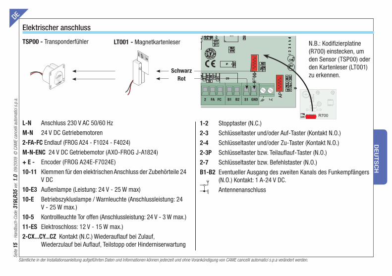
Elektrischer anschlussDE
L-N Anschluss 230 V AC 50/60 Hz
M-N 24 V DC Getriebemotoren
2-FA-FC Endlauf (FROG A24 - F1024 - F4024)
M-N-ENC 24 V DC Getriebemotor (AXO-FROG J-A1824)
+ E - Encoder (FROG A24E-F7024E)
10-11 Klemmen für den elektrischen Anschluss der Zubehörteile 24 V DC
10-E3 Außenlampe (Leistung: 24 V - 25 W max)
10-E Betriebszykluslampe / Warnleuchte (Anschlussleistung: 24 V - 25 W max.)
10-5 Kontrollleuchte Tor offen (Anschlussleistung: 24 V - 3 W max.)
11-ES Elektroschloss: 12 V - 15 W max.)
2-CX...CY...CZ Kontakt (N.C.) Wiederaufl auf bei Zulauf, Wiederzulauf bei Aufl auf, Teilstopp oder Hinderniserwartung
1-2 Stopptaster (N.C.)
2-3 Schlüsseltaster und/oder Auf-Taster (Kontakt N.O.)
2-4 Schlüsseltaster und/oder Zu-Taster (Kontakt N.O.)
2-3P Schlüsseltaster bzw. Teilaufl auf-Taster (N.O.)
2-7 Schlüsseltaster bzw. Befehlstaster (N.O.)
B1-B2 Eventueller Ausgang des zweiten Kanals des Funkempfängers (N.O.) Kontakt: 1 A-24 V DC.
Antennenanschluss
N.B.: Kodifizierplatine (R700) einstecken, um den Sensor (TSP00) oder den Kartenleser (LT001) zu erkennen.
TSP00 - Transponderfühler LT001 - Magnetkartenleser
CAME
ACC
ESS CO
NTR
OL
CANCELLI AUTOMATICI
R700
Schwarz
Rot
Sämtliche in der Installationsanleitung aufgeführten Daten und Informationen können jederzeit und ohne Vorankündigung von CAME cancelli automatici s.p.a verändert werden.
Sei
te 1
61
6
- H
andbuch
-Cod
e: 3
19
LR
35
31
9LR
35
ver
. 1
.01
.0 0
9/2
00
9 ©
CA
ME
cance
lli a
utom
atic
i s.p
.a.
DE
UTS
CH
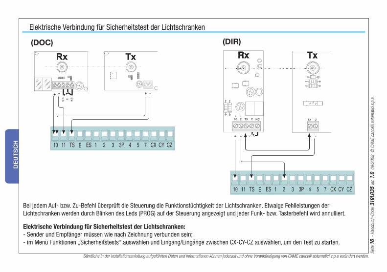
Bei jedem Auf- bzw. Zu-Befehl überprüft die Steuerung die Funktionstüchtigkeit der Lichtschranken. Etwaige Fehlleistungen der Lichtschranken werden durch Blinken des Leds (PROG) auf der Steuerung angezeigt und jeder Funk- bzw. Tasterbefehl wird annulliert.
Elektrische Verbindung für Sicherheitstest der Lichtschranken:
- Sender und Empfänger müssen wie nach Zeichnung verbunden sein;- im Menü Funktionen „Sicherheitstests“ auswählen und Eingang/Eingänge zwischen CX-CY-CZ auswählen, um den Test zu starten.
Elektrische Verbindung für Sicherheitstest der Lichtschranken
(DOC) (DIR)

Sei
te 1
717
- H
andbuch
-Cod
e: 3
19
LR
35
31
9LR
35
ver
. 1
.01
.0 0
9/2
00
9 ©
CA
ME
cance
lli a
utom
atic
i s.p
.a.
Sämtliche in der Installationsanleitung aufgeführten Daten und Informationen können jederzeit und ohne Vorankündigung von CAME cancelli automatici s.p.a verändert werden.
DE
UTS
CH
THERMAL Zum Rücksetzen der Einstellungen die Speicherkarte „Memory Roll” einstecken und wie in der Figur angegeben die Daten ablesen.
N.B.: Sollten die Einstellungen nicht in der „Memory Roll“ gespeichert worden sein, müssen sämtliche Einstellungen, wie in der Originalbetriebsanleitung der Steuerung beschrieben, neu eingestellt werden. Im Bedarfsfall fordern Sie beim Kundendienst eine Kopie an.
Speicher laden: die in der Memory Roll gespeicherten Daten auf die Steckkarte laden
X 2
Speicher laden
<Bestati.(nein) >
Speicher laden
<Bestati.(ja) >
<Speicher laden>
Speicher laden
LESE:250
< SPRACHE >
Deutschh
NUTZER
X 7
nnnn A
Memory roll
FUNKTIONENFUNKTIONE
ZEITEINSTELLUNEITEINSTEL
INFOINFO
Laufeinst.Laufeinst
Sämtliche in der Installationsanleitung aufgeführten Daten und Informationen können jederzeit und ohne Vorankündigung von CAME cancelli automatici s.p.a verändert werden.
Sei
te 1
81
8
- H
andbuch
-Cod
e: 3
19
LR
35
31
9LR
35
ver
. 1
.01
.0 0
9/2
00
9 ©
CA
ME
cance
lli a
utom
atic
i s.p
.a.
DE
UTS
CH
Entsorgung
L’ADMINISTRATEUR DÉLÉGUÉGianni Michielan
CAME Cancelli Automatici S.p.A.via Martiri della Libertà, 1531030 Dosson di Casier - Treviso - ITALYtel (+39) 0422 4940 - fax (+39) 0422 4941internet: www.came.it - e-mail: [email protected]
Bestätigt unter eigener Verantwortung, dass folgende automatische Antriebe für Tore und Garagentore:
.... den grundlegenden Anforderungen und entsprechenden Bestimmungen der folgenden Richtlinien und der anzuwendenden Teilbestimmungen der im folgenden aufgeführten Gesetzesvorschriften entsprechen.
2006/95/EG NIEDERSPANNUNGSRICHTLINIE 2004/108/EWG RICHTLINIE ÜBER ELEKTROMAGNETISCHE VERTRÄGLICHKEIT
EN 60335-1 EN 61000-6-2 EN 60335-2-103 EN 61000-6-3 EN 13241-1
EG-KONFORMITÄTSERKLÄRUNGGemäß der Niederspannungsrichtlinie
ZLJ14
Code zur Anforderung einer dem Original entsprechenden Kopie: DDF L DE Z002f
WICHTIGE HINWEISE !Ist es untersagt, die diese Erklärung betreffenden Produkte vor Fertigstellung und/oder Einbau gemäß den Bestimmungen der
Niederspannungsrichtlinie 2006/95/EWG zu verwenden.
Dieses Produkt einschließlich Verpackungen besteht aus verschiedenen wiederverwertbaren Materialien.
Informieren Sie sich unter Berücksichtigung der örtlich geltenden Rechtsvorschriften über die Recycling- und Entsorgungssysteme des Produkts.
Einige elektronische Bauteile könnte verschmutzende Substanzen enthalten - nicht in der Umwelt zerstreuen.
Pag
. 1
91
9
- C
odig
o m
anual
: 3
19
LR
35
31
9LR
35
ver
. 1
.01
.0 0
9/2
00
9 ©
CA
ME
cance
lli a
utom
atic
i s.p
.a.
Los datos y las informaciones indicadas en este manual de instalación podrían modificarse en cualquier momento y sin obligación de aviso previo por parte de la firma CAME cancelli automatici s.p.a.
ES
PA
ÑO
L
B1 B2 2 FA FC S1 GND
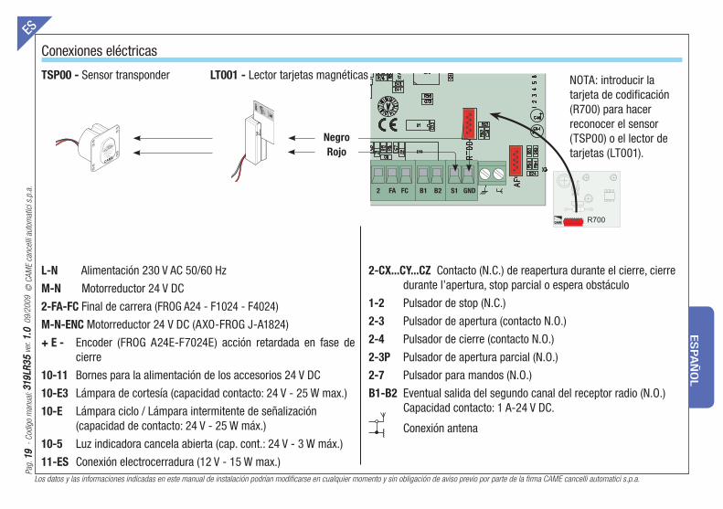
Conexiones eléctricasES
L-N Alimentación 230 V AC 50/60 Hz
M-N Motorreductor 24 V DC
2-FA-FC Final de carrera (FROG A24 - F1024 - F4024)
M-N-ENC Motorreductor 24 V DC (AXO-FROG J-A1824)
+ E - Encoder (FROG A24E-F7024E) acción retardada en fase de cierre
10-11 Bornes para la alimentación de los accesorios 24 V DC
10-E3 Lámpara de cortesía (capacidad contacto: 24 V - 25 W max.)
10-E Lámpara ciclo / Lámpara intermitente de señalización (capacidad de contacto: 24 V - 25 W máx.)
10-5 Luz indicadora cancela abierta (cap. cont.: 24 V - 3 W máx.)
11-ES Conexión electrocerradura (12 V - 15 W max.)
2-CX...CY...CZ Contacto (N.C.) de reapertura durante el cierre, cierre durante l’apertura, stop parcial o espera obstáculo
1-2 Pulsador de stop (N.C.)
2-3 Pulsador de apertura (contacto N.O.)
2-4 Pulsador de cierre (contacto N.O.)
2-3P Pulsador de apertura parcial (N.O.)
2-7 Pulsador para mandos (N.O.)
B1-B2 Eventual salida del segundo canal del receptor radio (N.O.) Capacidad contacto: 1 A-24 V DC.
Conexión antena
NOTA: introducir la tarjeta de codificación (R700) para hacer reconocer el sensor (TSP00) o el lector de tarjetas (LT001).
TSP00 - Sensor transponder LT001 - Lector tarjetas magnéticas
CAME
ACC
ESS CO
NTR
OL
CANCELLI AUTOMATICI
R700
Negro
Rojo
Los datos y las informaciones indicadas en este manual de instalación podrían modificarse en cualquier momento y sin obligación de aviso previo por parte de la firma CAME cancelli automatici s.p.a.
Pag
. 2
02
0
- C
odig
o m
anual
: 3
19
LR
35
31
9LR
35
ver
. 1
.01
.0 0
9/2
00
9 ©
CA
ME
cance
lli a
utom
atic
i s.p
.a.
ES
PA
ÑO
L
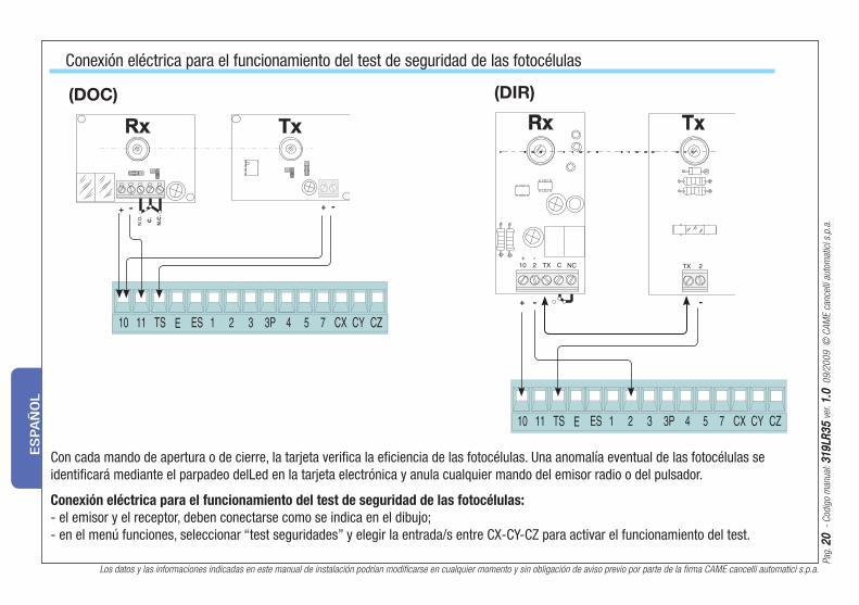
Con cada mando de apertura o de cierre, la tarjeta verifi ca la efi ciencia de las fotocélulas. Una anomalía eventual de las fotocélulas se identifi cará mediante el parpadeo delLed en la tarjeta electrónica y anula cualquier mando del emisor radio o del pulsador.
Conexión eléctrica para el funcionamiento del test de seguridad de las fotocélulas:
- el emisor y el receptor, deben conectarse como se indica en el dibujo;- en el menú funciones, seleccionar “test seguridades” y elegir la entrada/s entre CX-CY-CZ para activar el funcionamiento del test.
Conexión eléctrica para el funcionamiento del test de seguridad de las fotocélulas
(DOC) (DIR)
Pag
. 2
12
1
- C
odig
o m
anual
: 3
19
LR
35
31
9LR
35
ver
. 1
.01
.0 0
9/2
00
9 ©
CA
ME
cance
lli a
utom
atic
i s.p
.a.
Los datos y las informaciones indicadas en este manual de instalación podrían modificarse en cualquier momento y sin obligación de aviso previo por parte de la firma CAME cancelli automatici s.p.a.
ES
PA
ÑO
L
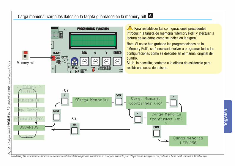
THERMAL Para restablecer las confi guraciones precedentes introducir la tarjeta de memoria “Memory Roll” y efectuar la lectura de los datos como se indica en la fi gura.
Nota: Si no se han grabado las programaciones en la “Memory Roll”, será necesario volver a programar todas las confi guraciones como se describe en el manual original del cuadro.Si Ud. lo necesita, contacte a la ofi cina de asistencia para recibir una copia del mismo.
Carga memoria: carga los datos en la tarjeta guardados en la memory roll
X 2
Carga Memoria
<confirmas (no)
>
Carga Memoria
<confirmas (si)
>
<Carga Memoria>
Carga Memoria
LEE:250
X 7< IDIOMA >
Italianono
USUARIOS
llll A
Memory roll
FUNCIONESFUNCIONE
REGULA TIEMPOSEGULA TIEM
INFOINFO
Imp. CarreraImp. Carre
Los datos y las informaciones indicadas en este manual de instalación podrían modificarse en cualquier momento y sin obligación de aviso previo por parte de la firma CAME cancelli automatici s.p.a.
Pag
. 2
22
2
- C
odig
o m
anual
: 3
19
LR
35
31
9LR
35
ver
. 1
.01
.0 0
9/2
00
9 ©
CA
ME
cance
lli a
utom
atic
i s.p
.a.
ES
PA
ÑO
L
Este producto, incluido el embalaje, está hecho con diferentes tipos de materiales que pueden reciclarse.
Infórmese sobre los sistemas de reciclaje o eliminación del producto, respetando las normas locales vigentes.
Algunos componentes electrónicos podrían contener substancias contaminantes; no los abandone en el medio ambiente.
Desguase
EL ADMINISTRADOR DELEGADOGianni Michielan
CAME Cancelli Automatici S.p.A.via Martiri della Libertà, 1531030 Dosson di Casier - Treviso - ITALYtel (+39) 0422 4940 - fax (+39) 0422 4941internet: www.came.it - e-mail: [email protected]
Declara bajo su exclusiva responsabilidad, que los siguientes productos para la automatización de cancelas y puertas para garajes, denominados del siguiente modo:
… son de conformidad con los requisitos esenciales y las disposiciones pertinentes, establecidos por las siguientes Directivas y con las partes aplicables de las Normativas de referencia que se indican a continuación.
2006/95/CE DIRECTIVA BAJA TENSIÓN
2004/104/CE DIRECTIVA COMPATIBILIDAD ELECTROMAGNÉTICA
EN 60335-1 EN 61000-6-2 EN 60335-2-103 EN 61000-6-3 EN 13241-1
DECLARACIÓN CE DE CONFORMIDADDe conformidad con la Directiva Baja Tensión
ZLJ14
Código de referencia para solicitar una copia de conformidad con la copia original: DDF L ES Z002f
ADVERTENCIA IMPORTANTE!Está prohibido hacer funcionar los productos, objeto de la presente
declaración, antes del completamiento y/o incorporación de los mismos (en la instalación fi nal), de conformidad con la Directiva Baja
Tensión 2006/95/CEE
Pag
. 2
32
3
- H
andle
idin
g num
mer
: 3
19
LR
35
31
9LR
35
ver
. 1
.01
.0 0
9/2
00
9 ©
CA
ME
cance
lli a
utom
atic
i s.p
.a.
De gegevens en informatie in deze handleiding voor de installatie zijn op elk ogenblik vatbaar voor wijziging zonder verplichting tot waarschuwing vooraf door Came Cancelli Automatici S.p.A.
NE
DE
RLA
ND
S
B1 B2 2 FA FC S1 GND
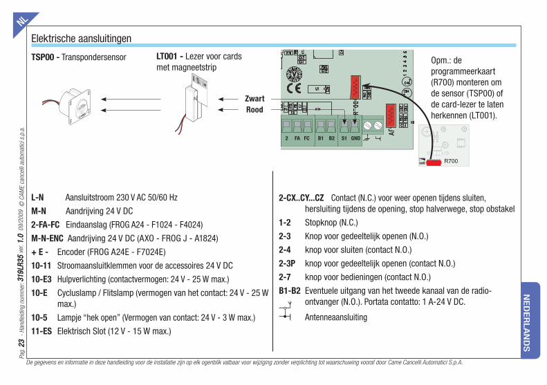
Elektrische aansluitingenNL
L-N Aansluitstroom 230 V AC 50/60 Hz
M-N Aandrijving 24 V DC
2-FA-FC Eindaanslag (FROG A24 - F1024 - F4024)
M-N-ENC Aandrijving 24 V DC (AXO - FROG J - A1824)
+ E - Encoder (FROG A24E - F7024E)
10-11 Stroomaansluitklemmen voor de accessoires 24 V DC
10-E3 Hulpverlichting (contactvermogen: 24 V - 25 W max.)
10-E Cycluslamp / Flitslamp (vermogen van het contact: 24 V - 25 W max.)
10-5 Lampje “hek open” (Vermogen van contact: 24 V - 3 W max.)
11-ES Elektrisch Slot (12 V - 15 W max.)
2-CX..CY...CZ Contact (N.C.) voor weer openen tijdens sluiten, hersluiting tijdens de opening, stop halverwege, stop obstakel
1-2 Stopknop (N.C.)
2-3 Knop voor gedeeltelijk openen (N.O.)
2-4 knop voor sluiten (contact N.O.)
2-3P knop voor gedeeltelijk openen (contact N.O.)
2-7 knop voor bedieningen (contact N.O.)
B1-B2 Eventuele uitgang van het tweede kanaal van de radio-ontvanger (N.O.). Portata contatto: 1 A-24 V DC.
Antenneaansluiting
Opm.: de programmeerkaart (R700) monteren om de sensor (TSP00) of de card-lezer te laten herkennen (LT001).
TSP00 - Transpondersensor LT001 - Lezer voor cards met magneetstrip
CAME
ACC
ESS CO
NTR
OL
CANCELLI AUTOMATICI
R700
Zwart
Rood

De gegevens en informatie in deze handleiding voor de installatie zijn op elk ogenblik vatbaar voor wijziging zonder verplichting tot waarschuwing vooraf door Came Cancelli Automatici S.p.A.
Pag
. 2
42
4
- H
andle
idin
g num
mer
: 3
19
LR
35
31
9LR
35
ver
. 1
.01
.0 0
9/2
00
9 ©
CA
ME
cance
lli a
utom
atic
i s.p
.a.
NE
DE
RLA
ND
S
Telkens als de poort wordt geopend of gesloten, controleert de kaartof de fotocellen werken. Een eventueel defect van de fotocellen wordt gesignaleerd met een knipperend controlelampje op de printkaart en annuleert elk commando van een afstandbediening of een bedieningsknop.
Elektrische aansluiting voor de fotocellentest:
- de zender en de ontvanger moeten worden aangesloten zoals op de tekening;- kies in het menu “functies” de “beveiligingentest” en kies de ingang(en) uit de CX-CY-CZ die u wenst te testen.
Elektrische aansluiting voor de fotocellentest
(DOC) (DIR)

Pag
. 2
52
5
- H
andle
idin
g num
mer
: 3
19
LR
35
31
9LR
35
ver
. 1
.01
.0 0
9/2
00
9 ©
CA
ME
cance
lli a
utom
atic
i s.p
.a.
De gegevens en informatie in deze handleiding voor de installatie zijn op elk ogenblik vatbaar voor wijziging zonder verplichting tot waarschuwing vooraf door Came Cancelli Automatici S.p.A.
NE
DE
RLA
ND
S
Om de vorige confi guraties te herstellen, steekt u de geheugenkaart “Memory Roll” erin en leest u de gegevens zoals u op de afbeelding kunt zien.
OPMERKING: Als de instellingen niet zijn opgeslagen op de “Memory Roll” moeten deze allemaal opnieuw worden uitgevoerd zoals is beschreven in de originele handleiding van het paneel.Verzoek indien nodig de hulpservice om een kopie.
Geheugen aanvullen: slaat de in het roll-geheugen opgeslagen gegevens op op de printkaart
X 2
Restore backup
<confirm? (no) >
Restore backup
<confirm? (yes)>
<Restore backup>
Restore backup
READ:250
< LANGUAGE >
Englishh
USERS
X 7
tt A
FUNCTIONSFUNCTION
TIMING ADJ.TIMING AD
INFOINFO
Imp. Runn
THERMAL
Memory roll
De gegevens en informatie in deze handleiding voor de installatie zijn op elk ogenblik vatbaar voor wijziging zonder verplichting tot waarschuwing vooraf door Came Cancelli Automatici S.p.A.
Pag
. 2
62
6
- H
andle
idin
g num
mer
: 3
19
LR
35
31
9LR
35
ver
. 1
.01
.0 0
9/2
00
9 ©
CA
ME
cance
lli a
utom
atic
i s.p
.a.
NE
DE
RLA
ND
S
Afvalverwerking
AFGEVAARDIGD BEHEERDERGianni Michielan
CAME Cancelli Automatici S.p.A.via Martiri della Libertà, 1531030 Dosson di Casier - Treviso - ITALYtel (+39) 0422 4940 - fax (+39) 0422 4941internet: www.came.it - e-mail: [email protected]
verklaart onder eigen verantwoordelijkheid, dat de volgende producten voor de automatisatie van hekken en garagepoorten, met name:
…conform de essentiële vereisten en de pertinente voorschriften zijn, vastgesteld door onderstaande Richtlijnen en door de toepasbare delen van het verwijzend Normenstelsel, die vervolgens worden vermeld.
2006/95/EG RICHTLIJN VAN DE LAAGSPANNING
2004/108/EEG RICHTLIJN VAN DE ELEKTROMAGNETISCHE COMPATIBILITEIT
EN 60335-1 EN 61000-6-2 EN 60335-2-103 EN 61000-6-3 EN 13241-1
EG-VERKLARING VAN OVEREENSTEMMINGVolgens de Richtlijn van Laagspanning
ZLJ14
Referentiecode voor het aanvragen van een conforme kopie van het origineel: DDF L NL Z002f
BELANGRIJKE WAARSCHUWING!Het is verboden om de producten te gebruiken, die onderhevig zijn aan deze verklaring, vooraleer ze wordten vervolledigd en/
of ingebouwd, conform de voorschriften van de Richtlijn van Laagspanning 2006/95/EEG.
Dit product, inclusief de verpakking, werd vervaardigd uit verschillende materialen die gerecycleerd kunnen worden.
Informeer in uw land over de recyclagemethoden of afvalverwerking van het product en volg de plaatselijke normen die van kracht zijn.
Elektronische onderdelen kunnen vervuilende stoffen bevatten: laat ze niet in het milieu achter.


FRANCE - CAME France S.a.CAME France S.a.7, Rue Des Haras - Z.i. Des Hautes Patures92737 Nanterre Cedex Nanterre Cedex - - (+33) 1 46 13 05 05 - (+33) 1 46 13 05 00
CAME GmbH NordCAME GmbH Nord - DEUTSCHLANDAkazienstraße, 9
16356 SeefeldSeefeld - (+49) 33 3988390 _ (+49) 33 39883985
FRANCE - CAME Automatismes S.a.CAME Automatismes S.a.3, Rue Odette Jasse13015 Marseille - Marseille - (+33) 4 95 06 33 70 - (+33) 4 91 60 69 05
CAME GmbH SüdCAME GmbH Süd - DEUTSCHLANDKornwestheimer Straße 37
70825 Korntal- Korntal-Münchingen - (+49) 71 5037830 _ (+49) 71 50378383
SPAIN - CAME Automatismos S.a.CAME Automatismos S.a.C/juan De Mariana, N. 17-local28045 Madrid - Madrid - (+34) 91 52 85 009 - (+34) 91 46 85 442
CAME Americas Automation LlcCAME Americas Automation Llc - U.S.A1560 Sawgrass Corporate Pkwy, 4th Floor
SunriseSunrise, FL 33323 - (+1) 305 433 3307 _ (+1) 305 396 3331
SPAIN - CAME Automatismos Catalunya S.a.CAME Automatismos Catalunya S.a.P.i. Moli Dels Frares N. 23 C/a08620 Sant Vicenc Del Horts Sant Vicenc Del Horts - - (+34) 93 65 67 694 - (+34) 93 67 24 505
CAME Middle East Fzco - CAME Middle East Fzco - U.A.E.Po Box 17131 Warehouse N. Be02 - South Zone, Jebel Ali Free Zone
DubaiDubai - (+971) 4 8860046 _ (+971) 4 8860048
PORTUGAL - Paf - CAMEPaf - CAMEEstrada Nacional 249-4 Ao Km 4,35 - Cabra Figa - Trajouce2635-047 Rio De Mouro - Rio De Mouro - (+351) 219 257 471 - (+35) 219 257 485
CAME Polska Sp.Zo.o - CAME Polska Sp.Zo.o - POLANDUl. Ordona 1
01-237 WarszawaWarszawa - (+48) 22 8365076 _ (+48) 22 8363296
UNITED KINGDOM - CAME United Kingdom Ltd.CAME United Kingdom Ltd.Unit 3 Orchard Business Park - Town Street, SandiacreNottingham Nottingham Ng10 5du - (+44) 115 9210430 - (+44) 115 9210431
S.c. CAME Romania S.r.l. - S.c. CAME Romania S.r.l. - ROMANIAB-dul Mihai Eminescu, Nr. 2, Bloc R2 - Scara A, Parter, Ap. 3
Buftea, Judet Ilfov BucarestBucarest - (+40) 21 3007344 _ (+40) 21 3007344
BELGIUM - CAME Belgium SprlCAME Belgium SprlZoning Ouest 77860 Lessines - Lessines - (+32) 68 333014 - (+32) 68 338019
CAME RussiaCAME Russia - RUSSIALeningradskij Prospekt, Dom 80 - Pod’ezd 3, offi ce 608
125190, MoskvaMoskva - (+7) 495 937 33 07 _ (+7) 495 937 33 08
ITALIA - CAME Cancelli Automatici S.p.a.CAME Cancelli Automatici S.p.a.Via Martiri Della Libertà, 1531030 Dosson Di Casier Dosson Di Casier (TV) - (+39) 0422 4940 _ (+39) 0422 4941Informazioni Commerciali 800 848095 - www.came.itwww.came.it
CAME Nord s.r.l.CAME Nord s.r.l. - ITALIAPiazza Castello, 16
20093 Cologno Monzese Cologno Monzese (MI) - (+39) 02 26708293 _ (+39) 02 25490288
ITALIA - CAME Service Italia S.r.l.CAME Service Italia S.r.l.Via Della Pace, 2831030 Dosson di Casier Dosson di Casier (TV) - (+39) 0422 383532 _ (+39) 0422 490044Assistenza Tecnica 800 295830Assistenza Tecnica 800 295830
CAME Sud s.r.l.CAME Sud s.r.l. - ITALIAVia F. Imparato, 198 - Cm2 Lotto A/7
80146 Napoli - Napoli - (+39) 081 7524455 _ (+39) 081 7529109
31
9LR
35
31
9LR
35
ver
. 1
.01
.0 0
9/2
00
9 ©
CA
ME
cance
lli a
utom
atic
i s.p
.a.