Vi ringraziamo per aver scelto un prodotto Devon&Devon. · The assembly instructions are supplied...
50
Transcript of Vi ringraziamo per aver scelto un prodotto Devon&Devon. · The assembly instructions are supplied...
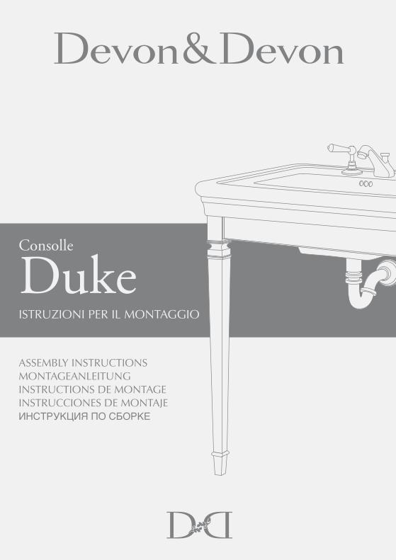
Vi ringraziamo per aver scelto un prodotto Devon&Devon.Vi preghiamo cortesemente di leggere questo manuale prima di installare il prodotto.
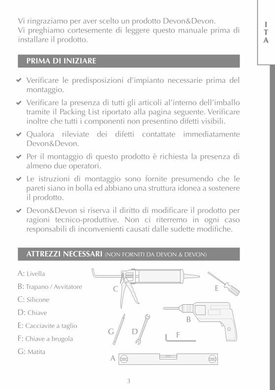
A: Livella
B: Trapano / Avvitatore
C: Silicone
D: Chiave
E: Cacciavite a taglio
F: Chiave a brugola
G: Matita
Verificare le predisposizioni d’impianto necessarie prima del montaggio.
Verificare la presenza di tutti gli articoli al’interno dell’imballo tramite il Packing List riportato alla pagina seguente. Verificare inoltre che tutti i componenti non presentino difetti visibili.
Qualora rileviate dei difetti contattate immediatamente Devon&Devon.
Per il montaggio di questo prodotto è richiesta la presenza di almeno due operatori.
Le istruzioni di montaggio sono fornite presumendo che le pareti siano in bolla ed abbiano una struttura idonea a sostenere il prodotto.
Devon&Devon si riserva il diritto di modificare il prodotto per ragioni tecnico-produttive. Non ci riterremo in ogni caso responsabili di inconvenienti causati dalle sudette modifiche.
PRIMA DI INIZIARE
ATTREZZI NECESSARI (NON FORNITI DA DEVON & DEVON)
3
A
C
B
E
G D F
ITA
ITA
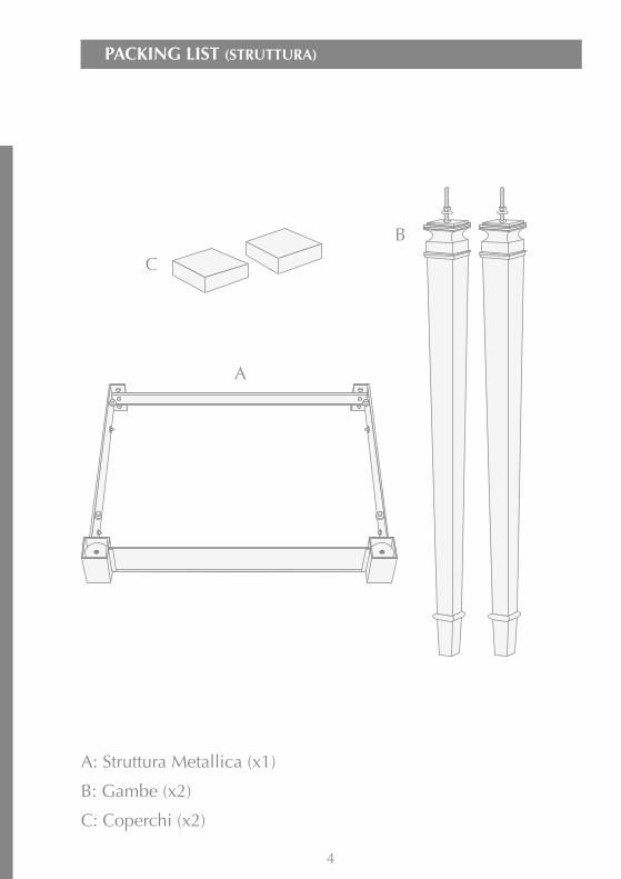
PACKING LIST (STRUTTURA)
4
A: Struttura Metallica (x1)
B: Gambe (x2)
C: Coperchi (x2)
B
A
C
5
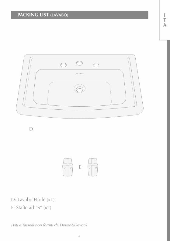
PACKING LIST (LAVABO) ITA
ITA
D: Lavabo Etoile (x1)
E: Staffe ad “S” (x2)
(Viti e Tasselli non forniti da Devon&Devon)
D
E

6
ISTRUZIONI DI MONTAGGIO
2) Inserire la gamba nella struttura metallica.
3) Inserire di nuovo la rondella nella barra filettata.
1) Dopo avere rimosso i componenti della struttura dall’imballo notate che nella barra filettata all’estremità superiore della gamba B sono presenti un dado e una rondella. Rimuoveteli dalla barra filettata.

7
ITA
ITA
4) Avvitare il dado serrando fino a bloccare rigidamente la gamba sulla struttura.
5) Ripetere le operazioni suddette per entrambe le gambe e presentare a muro la struttura così assemblata.
6) Tracciare i fori di fissaggio della struttura a muro (2 su ciascun lato).
7) Con la chiave a brugola smontare la barra distanziatrice sul retro della struttura, svitando le due viti che la fissano.
Verificare il posizionamento della struttura tramite una livella in direzione sia parallela che ortogonale a muro.

8
8) Rimuovere la struttura ed eseguire i 4 fori in base alla tracciatura.
9) Posizionare i coperchi agli angoli della struttura in corrispondenza della gambe.
10) Appoggiare sulla struttura il lavabo Etoile, cercando un buon compromesso tra l’appoggio sulla struttura e l’appoggio a muro.
Inserire i tasselli non forniti nei fori, posizionare di nuovo la struttura e fissarla con le viti anch’esse non fornite.
Se necessario intervenire sui supporti regolabili, usando il cacciavite a taglio.

9
ITA
ITA
12) A questo punto è possibile rimuovere il lavabo ed eseguire le forature a muro, rispettando le tracciature.
11) Una volta raggiunto il miglior compromesso possibile, posizionare le staffe ad “S” sotto al lavabo e tracciare i fori (2 per ciascuna staffa) per il loro fissaggio.
Montare le staffe di supporto del lavabo, fissandole con viti e tasselli (non forniti in dotazione).

10
15) Al termine la consolle dovrebbe apparire come mostrato.
13) Posizionare di nuovo il lavabo, inserendo la parte posteriore tra il lavabo ed il muro.
14) Applicare il silicone tra il lavabo ed il muro.

Thank you for choosing a Devon&Devon product.Please read this manual before installing the product.
A: Level
B: Drill / Screwdriver
C: Silicon
D: Wrench
E: Screwdriver
F: Allen wrench
G: Pencil
Please check the existing layout of the system required before assembly.
Verify the presence of all items inside the package using the Packing List included in the following page. Also verify that none of the components show visible defects.
If you should notice any defects please contact Devon&Devon immediately.
To assemble this product the presence of at least two people is necessary.
The assembly instructions are supplied with the assumption that the walls are perpendicular to the floor and that their structure is suitable to support the product.
Devon&Devon retains the right to modify the product for technical or production reasons. We will not be held responsible for any inconveniences caused by the above-mentioned changes.
BEFORE YOU BEGIN
TOOLS NEEDED (NOT SUPPLIED BY DEVON&DEVON)
11
A
C
B
E
G D F
ENG

PACKING LIST (STRUCTURE)
12
A: Metal structure (x1)
B: Legs (x2)
C: Covers (x2)
B
A
C
13
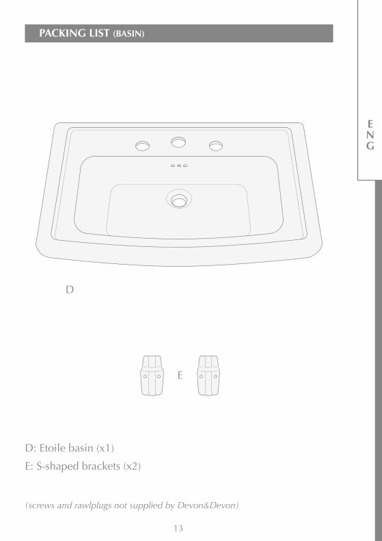
PACKING LIST (BASIN)
ENG
D: Etoile basin (x1)
E: S-shaped brackets (x2)
(screws and rawlplugs not supplied by Devon&Devon)
D
E
14
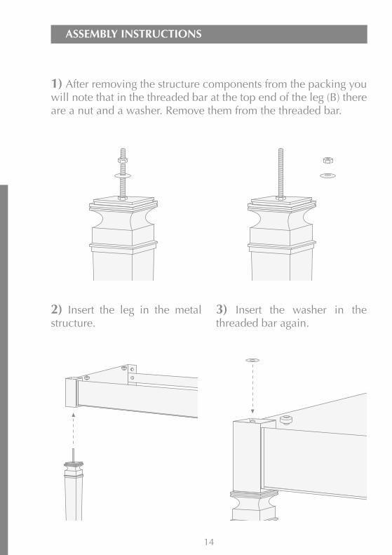
ASSEMBLY INSTRUCTIONS
2) Insert the leg in the metal structure.
3) Insert the washer in the threaded bar again.
1) After removing the structure components from the packing you will note that in the threaded bar at the top end of the leg (B) there are a nut and a washer. Remove them from the threaded bar.
15
ENG
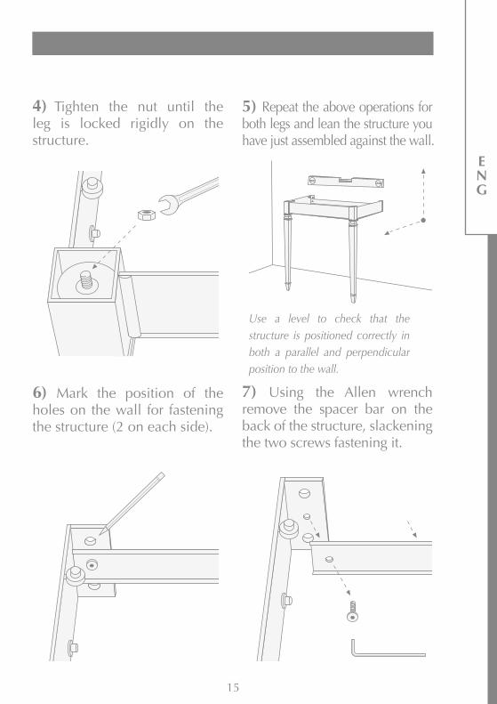
4) Tighten the nut until the leg is locked rigidly on the structure.
5) Repeat the above operations for both legs and lean the structure you have just assembled against the wall.
6) Mark the position of the holes on the wall for fastening the structure (2 on each side).
7) Using the Allen wrench remove the spacer bar on the back of the structure, slackening the two screws fastening it.
Use a level to check that the structure is positioned correctly in both a parallel and perpendicular position to the wall.

16
8) Remove the structure and drill the 4 holes as marked.
9) Position the covers at the corners of the structure in correspondence with the legs.
10) Rest the Etoile basin on the structure, finding a good compromise between resting on the structure and leaning against the wall.
Insert the rawl plugs which are not supplied in the holes, position the structure again and fasten it using screws which are not supplied.
If necessary, work on the adjustable supports using the screwdriver.
17
ENG
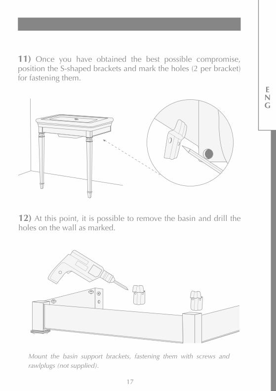
12) At this point, it is possible to remove the basin and drill the holes on the wall as marked.
11) Once you have obtained the best possible compromise, position the S-shaped brackets and mark the holes (2 per bracket) for fastening them.
Mount the basin support brackets, fastening them with screws and rawlplugs (not supplied).
18
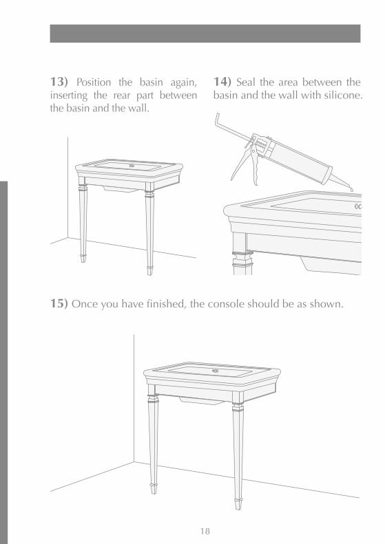
15) Once you have finished, the console should be as shown.
13) Position the basin again, inserting the rear part between the basin and the wall.
14) Seal the area between the basin and the wall with silicone.
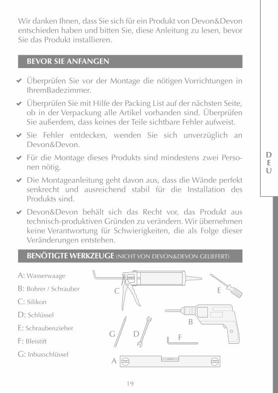
Wir danken Ihnen, dass Sie sich für ein Produkt von Devon&Devon entschieden haben und bitten Sie, diese Anleitung zu lesen, bevor Sie das Produkt installieren.
A: Wasserwaage
B: Bohrer / Schrauber
C: Silikon
D: Schlüssel
E: Schraubenzieher
F: Bleistift
G: Inbusschlüssel
Überprüfen Sie vor der Montage die nötigen Vorrichtungen in IhremBadezimmer.
Überprüfen Sie mit Hilfe der Packing List auf der nächsten Seite, ob in der Verpackung alle Artikel vorhanden sind. Überprüfen Sie außerdem, dass keines der Teile sichtbare Fehler aufweist.
Sie Fehler entdecken, wenden Sie sich unverzüglich an Devon&Devon.
Für die Montage dieses Produkts sind mindestens zwei Perso-nen nötig.
Die Montageanleitung geht davon aus, dass die Wände perfekt senkrecht und ausreichend stabil für die Installation des Produkts sind.
Devon&Devon behält sich das Recht vor, das Produkt aus technisch-produktiven Gründen zu verändern. Wir übernehmen keine Verantwortung für Schwierigkeiten, die als Folge dieser Veränderungen entstehen.
BEVOR SIE ANFANGEN
BENÖTIGTE WERKZEUGE (NICHT VON DEVON&DEVON GELIEFERT)
19
A
C
B
E
G D F
DEU

PACKING LIST (GESTELL)
20
A: Metallträger (x1)
B: Beine (x2)
C: Abdeckungen (x2)
B
A
C
21
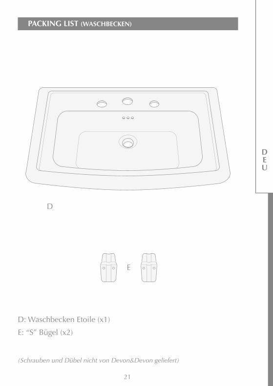
PACKING LIST (WASCHBECKEN)
DEU
D: Waschbecken Etoile (x1)
E: “S” Bügel (x2)
(Schrauben und Dübel nicht von Devon&Devon geliefert)
D
E

22
MONTAGEANLEITUNG
2) Das Bein in den Metallträger stecken.
3) Die Unterlegscheibe wieder in die Gewindestange einsetzen.
1) Die Bauteile aus der Verpackung nehmen. Auf der Gewindestange am oberen Ende des Beins (B) müssen eine Mutter und eine Unterlegscheibe vorhanden sein. Diese von der Gewindestange entfernen.
23
DEU
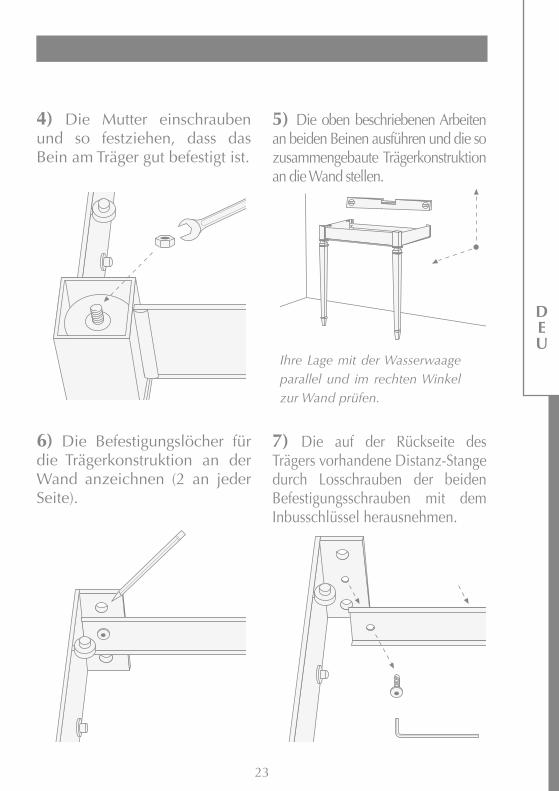
4) Die Mutter einschrauben und so festziehen, dass das Bein am Träger gut befestigt ist.
5) Die oben beschriebenen Arbeiten an beiden Beinen ausführen und die so zusammengebaute Trägerkonstruktion an die Wand stellen.
6) Die Befestigungslöcher für die Trägerkonstruktion an der Wand anzeichnen (2 an jeder Seite).
7) Die auf der Rückseite des Trägers vorhandene Distanz-Stange durch Losschrauben der beiden Befestigungsschrauben mit dem Inbusschlüssel herausnehmen.
Ihre Lage mit der Wasserwaage parallel und im rechten Winkel zur Wand prüfen.

24
8) Die Trägerkonstruktion wieder entfernen und die 4 markierten Löcher bohren.
9) Die Abdeckungen an den Ecken der Trägerkonstruktion entsprechend der Beine einsetzen.
10) Den Waschtisch Etoile auf den Träger setzen und seine Lage auf der Trägerkonstruktion und an der Wand ausgleichen.
Die nicht mitgelieferten Dübel in die Löcher einsetzen, die Trägerkonstruktion wieder positionieren und mit den nicht mitgelieferten Schrauben befestigen.
Falls erforderlich, die regelbaren Stützen mit dem Schlitzschraubendreher einstellen.
25
DEU
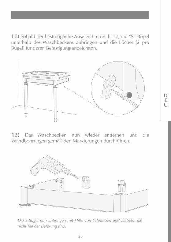
12) Das Waschbecken nun wieder entfernen und die Wandbohrungen gemäß den Markierungen durchführen.
11) Sobald der bestmögliche Ausgleich erreicht ist, die “S”-Bügel unterhalb des Waschbeckens anbringen und die Löcher (2 pro Bügel) für deren Befestigung anzeichnen.
Die S-Bügel nun anbringen mit Hilfe von Schrauben und Dübeln, die nicht Teil der Lieferung sind.

26
15) Zum Abschluss muss Konsole so aussehen, wie dargestellt.
13) Den Waschtisch wieder positionieren und den hinteren Teil zwischen Waschtisch und Wand einsetzen.
14) Silikon zwischen Waschtisch und Wand auftragen.
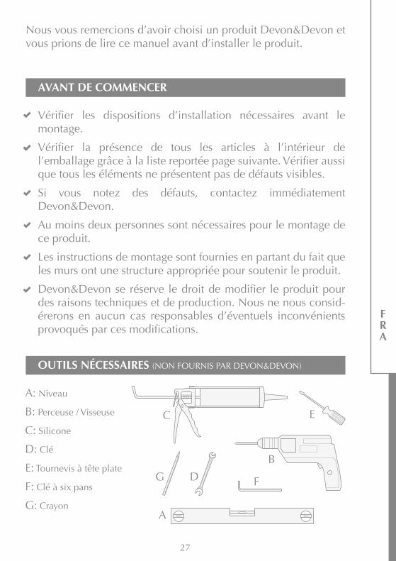
Nous vous remercions d’avoir choisi un produit Devon&Devon et vous prions de lire ce manuel avant d’installer le produit.
A: Niveau
B: Perceuse / Visseuse
C: Silicone
D: Clé
E: Tournevis à tête plate
F: Clé à six pans
G: Crayon
AVANT DE COMMENCER
OUTILS NÉCESSAIRES (NON FOURNIS PAR DEVON&DEVON)
27
Vérifier les dispositions d’installation nécessaires avant le montage.
Vérifier la présence de tous les articles à l’intérieur de l’emballage grâce à la liste reportée page suivante. Vérifier aussi que tous les éléments ne présentent pas de défauts visibles.
Si vous notez des défauts, contactez immédiatement Devon&Devon.
Au moins deux personnes sont nécessaires pour le montage de ce produit.
Les instructions de montage sont fournies en partant du fait que les murs ont une structure appropriée pour soutenir le produit.
Devon&Devon se réserve le droit de modifier le produit pour des raisons techniques et de production. Nous ne nous consid-érerons en aucun cas responsables d’éventuels inconvénients provoqués par ces modifications.
A
C
B
E
G D F
FRA

LISTE DES ACCESSOIRES (STRUCTURE)
28
A: Structure métallique (x1)
B: Pattes (x2)
C: Couvercles (x2)
B
A
C

29
LISTE DES ACCESSOIRES (LAVABO)
FRA
D: Lavabo Etoile (x1)
E: Etriers en “S” (x2)
(vis et chevilles non fournies par Devon&Devon)
D
E

30
MONTAGE
2) Insérez la patte dans la structure métallique.
3) Insérez à nouveau la rondelle dans la barre filetée.
1) Après avoir enlevé les pièces de l'emballage, vous remarquerez qu'un écrou et une rondelle sont présents dans la barre filetée à l'extrémité supérieure de la patte (B). Enlevez-les de la barre filetée.

31
FRA
4) Vissez l’écrou et serrez jusqu’à bloquer rigidement la patte sur la structure.
5) Répétez les opérations susvisées pour les deux pattes et adossez la structure assemblée au mur.
6) Tracez les trous de fixation de la structure au mur (2 sur chaque côté).
7) A l’aide de la clé à six pans démontez la barre d’écartement située sur la partie arrière de la structure, dévissant les deux vis.
Vérifiez le positionnement de la structure à l’aide d’un niveau en direction tant parallèle que perpendiculaire au mur.

32
8) Retirez la structure et réalisez les 4 trous en fonction du traçage.
9) Placez les couvercles sur les angles de la structure à hauteur de la patte.
10) Appuyez le lavabo Etoile sur la structure, cherchant un compromis entre l’appui sur la structure et l’appui sur le mur.
Introduisez les chevilles fournies, positionnez à nouveau la structure et fixez-la à l'aide des vis fournies.
Le cas échéant, intervenez sur les supports réglables, en utilisant le tournevis à tête plate.
33
FRA
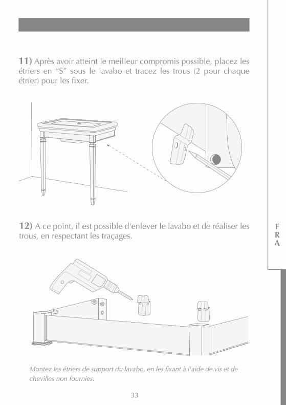
12) A ce point, il est possible d'enlever le lavabo et de réaliser les trous, en respectant les traçages.
11) Après avoir atteint le meilleur compromis possible, placez les étriers en “S” sous le lavabo et tracez les trous (2 pour chaque étrier) pour les fixer.
Montez les étriers de support du lavabo, en les fixant à l'aide de vis et de chevilles non fournies.

34
15) A la fin des opérations, la console devrait apparaître comme dans l'illustration ci-contre.
13) Positionnez à nouveau le lavabo, en introduisant la partie arrière entre le lavabo et le mur.
14) Appliquez le silicone entre le lavabo et le mur.
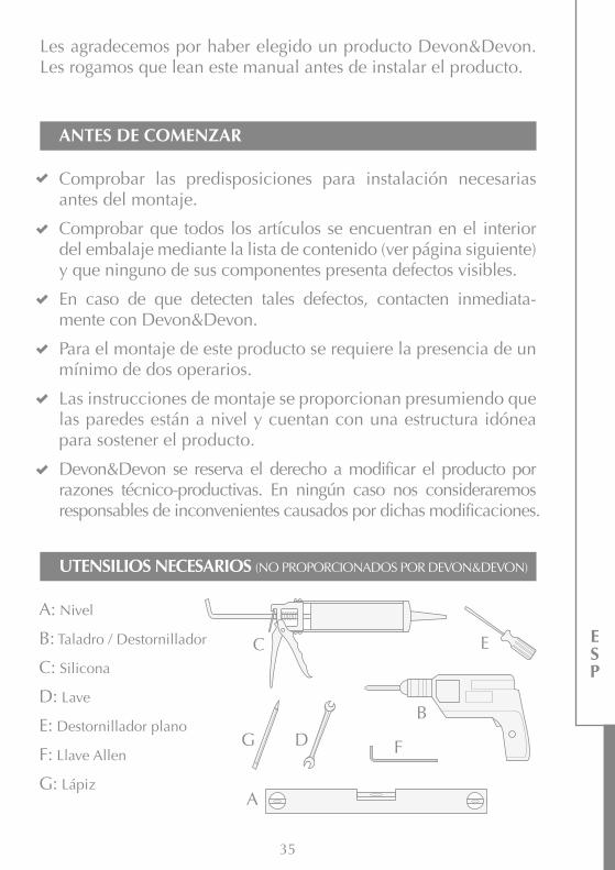
Les agradecemos por haber elegido un producto Devon&Devon. Les rogamos que lean este manual antes de instalar el producto.
A: Nivel
B: Taladro / Destornillador
C: Silicona
D: Lave
E: Destornillador plano
F: Llave Allen
G: Lápiz
Comprobar las predisposiciones para instalación necesarias antes del montaje.
Comprobar que todos los artículos se encuentran en el interior del embalaje mediante la lista de contenido (ver página siguiente) y que ninguno de sus componentes presenta defectos visibles.
En caso de que detecten tales defectos, contacten inmediata-mente con Devon&Devon.
Para el montaje de este producto se requiere la presencia de un mínimo de dos operarios.
Las instrucciones de montaje se proporcionan presumiendo que las paredes están a nivel y cuentan con una estructura idónea para sostener el producto.
Devon&Devon se reserva el derecho a modificar el producto por razones técnico-productivas. En ningún caso nos consideraremos responsables de inconvenientes causados por dichas modificaciones.
ANTES DE COMENZAR
UTENSILIOS NECESARIOS (NO PROPORCIONADOS POR DEVON&DEVON)
35
A
C
B
E
G D F
ESP
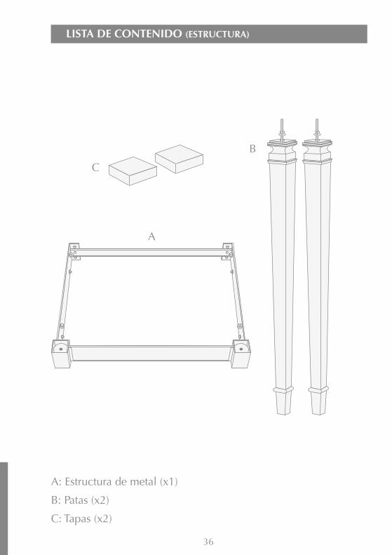
LISTA DE CONTENIDO (ESTRUCTURA)
36
A: Estructura de metal (x1)
B: Patas (x2)
C: Tapas (x2)
B
A
C
37
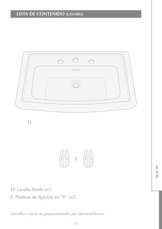
LISTA DE CONTENIDO (LAVABO)
ESP
D: Lavabo Etoile (x1)
E: Platinas de fijación en “S” (x2)
(tornillos y tacos no proporcionados por Devon&Devon)
D
E
38
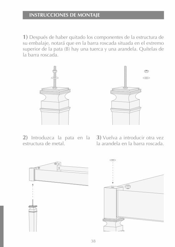
INSTRUCCIONES DE MONTAJE
2) Introduzca la pata en la estructura de metal.
3) Vuelva a introducir otra vez la arandela en la barra roscada.
1) Después de haber quitado los componentes de la estructura de su embalaje, notará que en la barra roscada situada en el extremo superior de la pata (B) hay una tuerca y una arandela. Quítelas de la barra roscada.
39
ESP
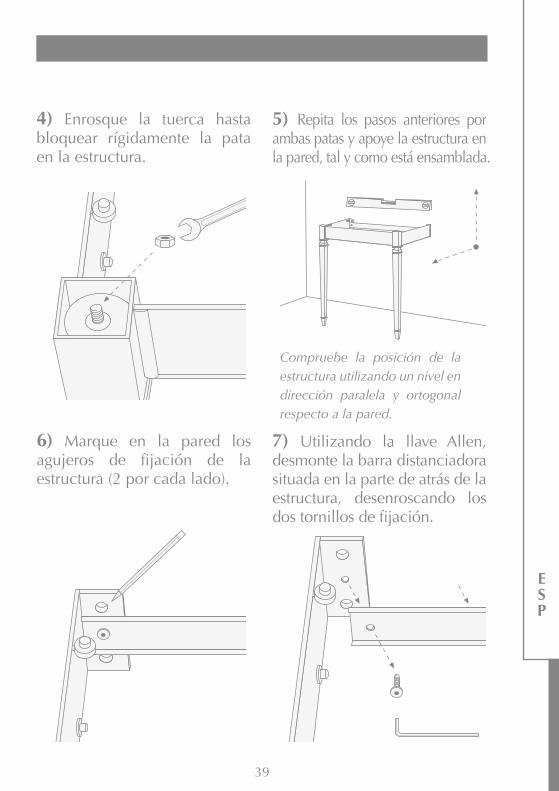
4) Enrosque la tuerca hasta bloquear rígidamente la pata en la estructura.
5) Repita los pasos anteriores por ambas patas y apoye la estructura en la pared, tal y como está ensamblada.
6) Marque en la pared los agujeros de fijación de la estructura (2 por cada lado).
7) Utilizando la llave Allen, desmonte la barra distanciadora situada en la parte de atrás de la estructura, desenroscando los dos tornillos de fijación.
Compruebe la posición de la estructura utilizando un nivel en dirección paralela y ortogonal respecto a la pared.

40
8) Aparte la estructura y haga 4 agujeros en las marcas.
9) Coloque las tapas en los ángulos de la estructura, en correspondencia de las patas.
10) Apoye en la estructura el lavabo Étoile, comprobando que quede bien colocado, tanto en la estructura, como en la pared.
Inroduzca los tacos en los agujeros, coloque otra vez la estructura y fíjela con los tornillos (tacos y tornillos no proporcionados por Devon&Devon).
Si es necesario, intervenga en los soportes ajustables, utilizando el destornillador plano.
41
ESP
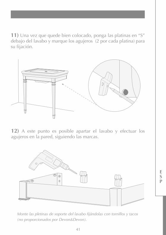
12) A este punto es posible apartar el lavabo y efectuar los agujeros en la pared, siguiendo las marcas.
11) Una vez que quede bien colocado, ponga las platinas en “S” debajo del lavabo y marque los agujeros (2 por cada platina) para su fijación.
Monte las pletinas de soporte del lavabo fijándolas con tornillos y tacos (no proporcionados por Devon&Devon).
42
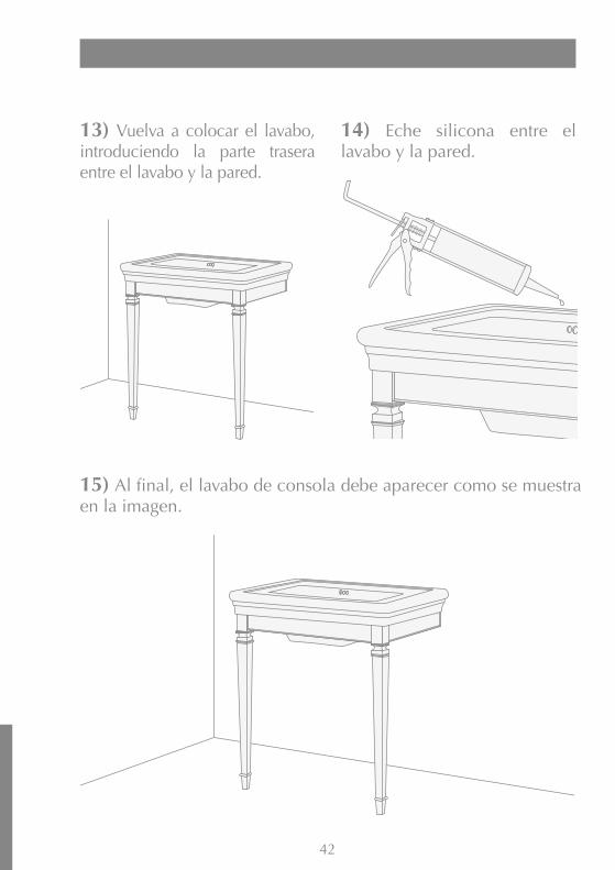
15) Al final, el lavabo de consola debe aparecer como se muestra en la imagen.
13) Vuelva a colocar el lavabo, introduciendo la parte trasera entre el lavabo y la pared.
14) Eche silicona entre el lavabo y la pared.

Благодарим за выбор изделия Devon&Devon.Перед установкой внимательно прочитайте настоящую инструкцию.
A: Уровень
B: Сверло-гайковерт
C: Силикон
D:.Ключ
E:.Прямошлицевая отвертка
F: Инбусовый ключ
G: Карандаш
Перед тем, как приступать к сборке, убедиться в наличии всех элементов структуры.
Проверить наличие всех деталей внутри упаковки, в соответствии с Упаковочным листом, приведенным на следующей странице. Убедиться, что детали не имеют видимых дефектов. При выявлении каких-либо дефектов, немедленно сообщить производителю Devon&Devon.
Для монтажа данного изделия необходимо участие, по крайней мере, двух рабочих.
Данная инструкция рассчитана на то, что установка изделия будет производиться на ровную стену, со структурой, способной выдержать изделие.
Devon&Devon оставляет за собой право вносить изменения в изделия в случае технической или производственной необходимости. В любом случае мы не несем никакой ответственности за неудобство, причиненное вышеуказанными изменениями.
ПЕРЕД НАЧАЛОМ СБОРКИ
НЕОБХОДИМЫЕ ИНСТРУМЕНТЫ (НЕ ВКЛЮЧЕНЫ ПРОИЗВОДИТЕЛЕМ В КОМПЛЕКТ)
43
A
C
B
E
G D F
PYC

УПАКОВОЧНЫЙ ЛИСТ (ОСНОВНАЯ КОНСТРУКЦИЯ)
44
A: Металлическая конструкция (x1)
B: Ножки (x2)
C: Колпачки (x2)
B
A
C

45
УПАКОВОЧНЫЙ ЛИСТ (РАКОВИНА)
PYC
D: Раковина Etoile (x1)
E: Скобы S-образные (x2)
(винты и дюбели не входят в поставку Devon&Devon)
D
E

46
ИНСТРУКЦИЯ ПО СБОРКЕ
2) Вставьте ножку в металлическую конструкцию.
3) Установите снова шайбу на резьбовой стержень.
1) Вынув комплектующие элементы конструкции из упаковки вы увидите, что на резьбовом стержне в верхней части ножки (B) навинчены гайка и шайба. Удалите их с резьбового стержня.

47
PYC
4) Завинтите шайбу и затяните ее так, чтобы ножка была крепко фиксирована на конструкции.
5) Повторить описанные выше операции для обеих ножек и приставить к стене собранную таким образом конструкцию.
6) Отметить карандашом место для отверстий на стене для крепления конструкции (по 2 с каждой стороны).
7) Снять распорную планку на задней стороне конструкции, вывернув инбусовым ключом два соответствующих крепежных винта.
Проверить уровнем ее параллельное и ортогональное положение по отношению к стене.

48
8) Отнять конструкцию от стены и просверлить 4 отверстия в отмеченных местах.
9) Установить колпачки по углам конструкции в местах напротив ножек.
10) Установить на конструкцию раковину Etoile, стараясь найти ровное положение как на конструкции, так и для упора к стене.
Вставить по дюбелю в каждое отверстие, снова установить конструкцию и зафиксировать ее соответствующими винтами, которые как и дюбели не поставляются поставщиком мебели.
При необходимости отрегулировать опоры при помощи прямошлицевой отвертки.
49
PYC
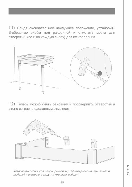
12) Теперь можно снять раковину и просверлить отверстия в стене согласно сделанным отметкам.
11) Найдя окончательное наилучшее положение, установить S-образные скобы под раковиной и отметить места для отверстий (по 2 на каждую скобу) для их крепления.
Установить скобы для опоры раковины, зафиксировав их при помощи дюбелей и винтов (не входят в комплект мебели).
50
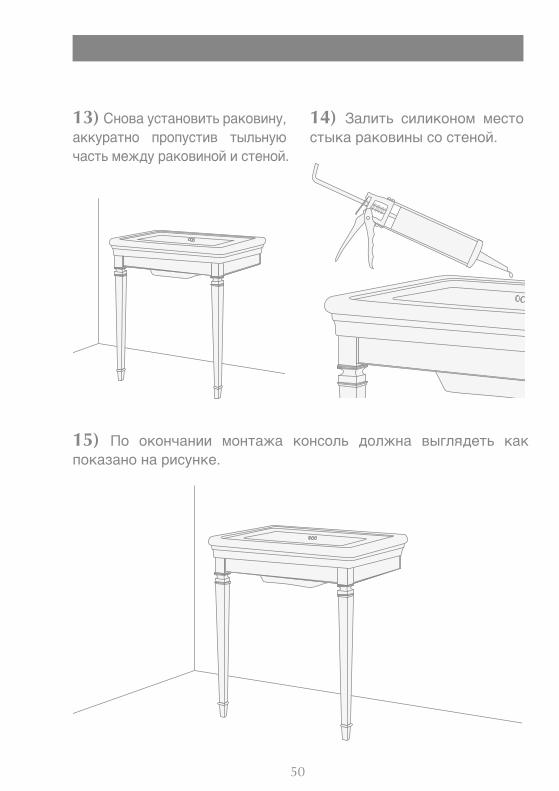
15) По окончании монтажа консоль должна выглядеть как показано на рисунке.
13) Снова установить раковину, аккуратно пропустив тыльную часть между раковиной и стеной.
14) Залить силиконом место стыка раковины со стеной.

Devon & DevonVia Arno, 26 - 50019 - Sesto Fiorentino (FI)
Tel. 0039 055 308350 - Fax 0039 055 375549
www.devon-devon.comemail: [email protected]
LightingASSEMBLY INSTRUCTIONS
ISTRUZIONI PER IL MONTAGGIOMONTAGEANLEITUNG
INSTRUCTIONS DE MONTAGEINSTRUCCIONES DE MONTAJE
ИНСТРУКЦИЯ ПО СБОРКЕ