VALVOLE REGOLATRICI DI FLUSSO - · PDF fileValvole regolatrici di flusso che permettono il...
17
FLOW REGULATOR VALVES 7 VALVOLE REGOLATRICI DI FLUSSO
Transcript of VALVOLE REGOLATRICI DI FLUSSO - · PDF fileValvole regolatrici di flusso che permettono il...

FLOW REGULATOR VALVES
7
VALVOLE REGOLATRICI DI FLUSSO

FLUSSO LIBEROFREE FLOW
FLUSSO REGOLATOREGULATED FLOW
C V
CODICECODE
SIGLATYPE
PORTATA MAXMAX FLOW
Lt./min
PRESSIONE MAXMAX PRESSURE
Bar
PRESSIONE APERTURACRACKING PRESSURE
Bar
V0540 VRF ¼” 20 300 0,5
V0550 VRF ⅜” 45 300 0,5
V0560 VRF ½” 70 300 0,5
V0570 VRF ¾” 110 250 0,5
V0580 VRF 1” 160 250 0,5
CODICECODE
SIGLATYPE
V - C L E/ CH D PESOWEIGHT
GAS mm mm mm mm Kg
V0540 VRF ¼” G ¼” 66,5 30 19 34 0,274
V0550 VRF ⅜” G ⅜” 73 32 24 36 0,330
V0560 VRF ½” G ½” 80 38 27 42 0,484
V0570 VRF ¾” G ¾” 95 46 32 51 0,824
V0580 VRF 1” G 1” 109 55 41 60 1,314
0
1
2
3
4
5
6
0 20 40 60 80 100 120 140 160 180
FLOW - Q (l/min)
VRF 3/8"
VRF 1/4"
VRF 1/2"
VRF 3/4"
VRF 1"
V C
ΔP
(Bar
)
0
2
4
6
8
10
12
14
16
0 20 40 60 80 100 120 140 160 180FLOW - Q (l/min)
VRF 3/8"
VRF 1/4"
VRF 1/2"
VRF 3/4"
VRF 1"
C V
ΔP
(Bar
)
STROZZATORE TUTTO CHIUSO - FULLY CLOSED THROTTLE STROZZATORE TUTTO APERTO - FULLY OPENED THROTTLE
OLEODINAMICA MARCHESINI
136
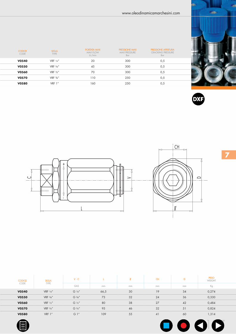
PERDITE DI CARICOPRESSURE DROPS CURVE
SCHEMA IDRAULICOHYDRAULIC DIAGRAM
7.1 - VALVOLE DI REGOLAZIONEFLUSSO UNIDIREZIONALI A MANICOTTO7.1 - BARREL FLOW CONTROL VALVES WITH CHECK
IMPIEGO:Valvole che permettono di regolare la velocità di un attuatore in una direzione e consentono il flusso libero nell’altra. Non essendo compensate alla pressione, la regolazione del fluido dipenderà dalla pressione e dalla viscosità dell’olio.
MATERIALI E CARATTERISTICHE:Corpo e camicia: acciaio zincatoComponenti interni: acciaio temprato termicamente e rettificatoGuarnizioni: BUNA N standardTenuta: per accoppiamento. Trafilamento trascurabile a valvola chiusa
MONTAGGIO:Collegare V all’alimentazione e C all’attuatore da regolare. Il flusso è regolato da C a V e libero nel senso opposto. In caso di impiego su attuatori con valvola di blocco, la VRF va montata tra attuatore e valvola di blocco.La regolazione del flusso si effettua tramite la rotazione del manicotto esterno: ruotando in senso orario si aumenta il flusso e viceversa. Una volta regolata la portata, riportare la ghiera di fermo in posizione in modo da mantenere i valori impostati anche in presenza di vibrazioni.
USE AND OPERATIONThis valve is used to adjust flow speed of actuators in one direction; flow is free in the reverse one. As pressure compensation is not provided, flow adjustment depends on pressure and oil viscosity.
MATERIALS AND FEATURES:Body: zinc-plated steelInternal parts: hardened and ground steelSeal: BUNA N standardTightness: by diameter combination. Minor leakage with closed valve
APPLICATIONS:Connect V to the pressure flow and C to the actuator to set. The flow is adjusted from C to V and free in the reverse direction. When used on actuator with double pilot check valve, VRF has to be mounted between the actuator and the double pilot check valve.Flow adjustment is made by rotating the coupling: by clockwise rotation flow increases and vice versa. Once the flow has been set, lock the nut in order to keep the desired settings even in case of vibrations.
TIPO/TYPE
VRF
Temperatura olio: 50°C - Viscosità olio: 30 cStOil temperature: 50°C - Oil viscosity: 30 cSt
7
CODICECODE
SIGLATYPE
PORTATA MAXMAX FLOW
Lt./min
PRESSIONE MAXMAX PRESSURE
Bar
PRESSIONE APERTURACRACKING PRESSURE
Bar
V0540 VRF ¼” 20 300 0,5
V0550 VRF ⅜” 45 300 0,5
V0560 VRF ½” 70 300 0,5
V0570 VRF ¾” 110 250 0,5
V0580 VRF 1” 160 250 0,5
CODICECODE
SIGLATYPE
V - C L E/ CH D PESOWEIGHT
GAS mm mm mm mm Kg
V0540 VRF ¼” G ¼” 66,5 30 19 34 0,274
V0550 VRF ⅜” G ⅜” 73 32 24 36 0,330
V0560 VRF ½” G ½” 80 38 27 42 0,484
V0570 VRF ¾” G ¾” 95 46 32 51 0,824
V0580 VRF 1” G 1” 109 55 41 60 1,314
L
C V
CH
D
E/
+
-
www.oleodinamicamarchesini.com
137
FLUSSO REGOLATOREGULATED FLOW
FLUSSO REGOLATOREGULATED FLOW
C V
CODICECODE
SIGLATYPE
PORTATA MAXMAX FLOW
Lt./min
PRESSIONE MAXMAX PRESSURE
Bar
V0545 VRB ¼” 20 300
V0555 VRB ⅜” 45 300
V0565 VRB ½” 70 300
V0575 VRB ¾” 110 250
V0585 VRB 1” 160 250
CODICECODE
SIGLATYPE
V - C L E/ CH D PESOWEIGHT
GAS mm mm mm mm Kg
V0545 VRB ¼” G ¼” 66,5 30 19 34 0,266
V0555 VRB ⅜” G ⅜” 73 32 24 36 0,312
V0565 VRB ½” G ½ ” 80 38 27 42 0,456
V0575 VRB ¾” G ¾” 95 46 32 51 0,784
V0585 VRB 1” G 1” 109 55 41 60 1,222
0
2
4
6
8
10
12
14
16
0 20 40 60 80 100 120 140 160 180
FLOW - Q (l/min)
VRB 3/8"
VRB 1/4"
VRB 1/2"
VRB 3/4"
VRB1"
C V
ΔP
(Bar
)
STROZZATORE TUTTO APERTO - FULLY OPENED THROTTLE
OLEODINAMICA MARCHESINI
138
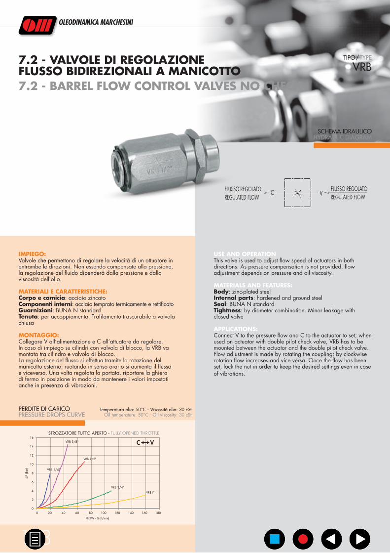
PERDITE DI CARICOPRESSURE DROPS CURVE
SCHEMA IDRAULICOHYDRAULIC DIAGRAM
7.2 - VALVOLE DI REGOLAZIONEFLUSSO BIDIREZIONALI A MANICOTTO7.2 - BARREL FLOW CONTROL VALVES NO CHECK
IMPIEGO:Valvole che permettono di regolare la velocità di un attuatore in entrambe le direzioni. Non essendo compensate alla pressione, la regolazione del fluido dipenderà dalla pressione e dalla viscosità dell’olio.
MATERIALI E CARATTERISTICHE:Corpo e camicia: acciaio zincatoComponenti interni: acciaio temprato termicamente e rettificatoGuarnizioni: BUNA N standardTenuta: per accoppiamento. Trafilamento trascurabile a valvola chiusa
MONTAGGIO:Collegare V all’alimentazione e C all’attuatore da regolare. In caso di impiego su cilindri con valvola di blocco, la VRB va montata tra cilindro e valvola di blocco.La regolazione del flusso si effettua tramite la rotazione del manicotto esterno: ruotando in senso orario si aumenta il flusso e viceversa. Una volta regolata la portata, riportare la ghiera di fermo in posizione in modo da mantenere i valori impostati anche in presenza di vibrazioni.
USE AND OPERATIONThis valve is used to adjust flow speed of actuators in both directions. As pressure compensation is not provided, flow adjustment depends on pressure and oil viscosity.
MATERIALS AND FEATURES:Body: zinc-plated steelInternal parts: hardened and ground steelSeal: BUNA N standardTightness: by diameter combination. Minor leakage with closed valve
APPLICATIONS:Connect V to the pressure flow and C to the actuator to set; when used on actuator with double pilot check valve, VRB has to be mounted between the actuator and the double pilot check valve.Flow adjustment is made by rotating the coupling: by clockwise rotation flow increases and vice versa. Once the flow has been set, lock the nut in order to keep the desired settings even in case of vibrations.
TIPO/TYPE
VRB
Temperatura olio: 50°C - Viscosità olio: 30 cStOil temperature: 50°C - Oil viscosity: 30 cSt
7
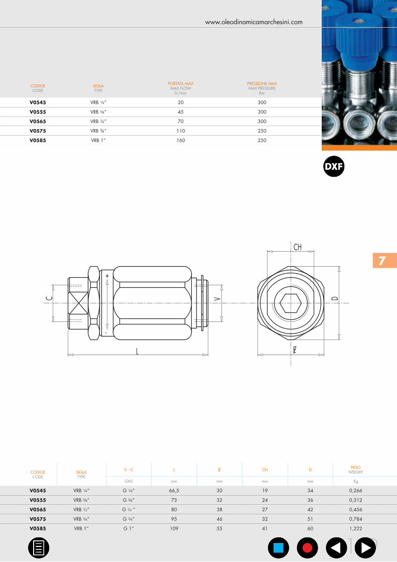
CODICECODE
SIGLATYPE
PORTATA MAXMAX FLOW
Lt./min
PRESSIONE MAXMAX PRESSURE
Bar
V0545 VRB ¼” 20 300
V0555 VRB ⅜” 45 300
V0565 VRB ½” 70 300
V0575 VRB ¾” 110 250
V0585 VRB 1” 160 250
CODICECODE
SIGLATYPE
V - C L E/ CH D PESOWEIGHT
GAS mm mm mm mm Kg
V0545 VRB ¼” G ¼” 66,5 30 19 34 0,266
V0555 VRB ⅜” G ⅜” 73 32 24 36 0,312
V0565 VRB ½” G ½ ” 80 38 27 42 0,456
V0575 VRB ¾” G ¾” 95 46 32 51 0,784
V0585 VRB 1” G 1” 109 55 41 60 1,222
L
C V
CH
D
E/
+
-
www.oleodinamicamarchesini.com
139

FLUSSO LIBEROFREE FLOWC V
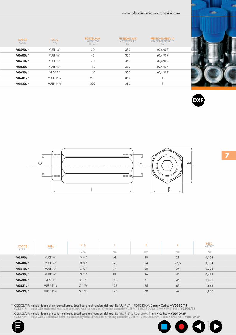
CODICECODE
SIGLATYPE
PORTATA MAXMAX FLOW
Lt./min
PRESSIONE MAXMAX PRESSURE
Bar
PRESSIONE APERTURACRACKING PRESSURE
Bar
V0590/* VUSF ¼” 20 350 ±0,4/0,7
V0600/* VUSF ⅜” 45 350 ±0,4/0,7
V0610/* VUSF ½” 70 350 ±0,4/0,7
V0620/* VUSF ¾” 110 350 ±0,4/0,7
V0630/* VUSF 1” 160 350 ±0,4/0,7
V0631/* VUSF 1”¼ 200 350 1
V0632/* VUSF 1”½ 300 350 1
CODICECODE
SIGLATYPE
V - C L E/ D PESOWEIGHT
GAS mm mm mm Kg
V0590/* VUSF ¼” G ¼” 62 19 21 0,104
V0600/* VUSF ⅜” G ⅜” 68 24 26,5 0,184
V0610/* VUSF ½” G ½” 77 30 34 0,322
V0620/* VUSF ¾” G ¾” 88 36 40 0,492
V0630/* VUSF 1” G 1” 105 41 46 0,676
V0631/* VUSF 1”¼ G 1”¼ 135 55 63 1,646
V0632/* VUSF 1”½ G 1”½ 145 60 69 1,950
0
1
2
3
4
5
6
7
0 10 20 30 40 50 60 70 80 90 100
FLOW - Q (l/min)
VUSF 1/4"
VUSF 3/8"
VUSF 1/2"
VUSF 3/4"
ΔP
(Bar
)
0
0,5
1
1,5
2
2,5
3
0 50 100 150 200 250 300
FLOW - Q (l/min)
VUSF 1"
VUSF 1"1/4VUSF 1"1/2
ΔP
(Bar
)
OLEODINAMICA MARCHESINI
140
PERDITE DI CARICOPRESSURE DROPS CURVE
SCHEMA IDRAULICOHYDRAULIC DIAGRAM
7.3 - VALVOLE UNIDIREZIONALIDI STROZZAMENTO FISSE7.3 - FIXED SETTING THROTTLE CHECK VALVES
IMPIEGO:Valvole regolatrici di flusso che permettono il flusso libero in una direzione e lo controllano in quella opposta. La portata è regolata dal diametro del foro di strozzamento ed è pertanto fissa.
MATERIALI E CARATTERISTICHE:Corpo: acciaio zincatoComponenti interni: acciaio temprato termicamente e rettificatoGuarnizioni: BUNA N standardTenuta: a cono guidato
MONTAGGIO:Collegare V all’alimentazione e C all’attuatore. Il flusso passa libero da V a C ed è controllato nel senso opposto. Lo strozzamento è ottenuto mediante uno o due fori calibrati, il cui diametro dovrà essere specificato in fase d’ordine.
A RICHIESTA:•Pressioned’aperturadiversadaquellastandard:1-3-5-8Bar
(specificare nella descrizione il valore di pressione desiderato)
USE AND OPERATIONFlow is free in one direction and fixed in the reverse one. Flow is fixed as flow adjustment depends on the throttling hole diameter.
MATERIALS AND FEATURES:Body: zinc-plated steelInternal parts: hardened and ground steelSeal: BUNA N standardPoppet type: standard
APPLICATIONS:Connect V to the pressure flow and C to the actuator. Flow is free from V to C and fixed in the reverse one. Throttling is obtained through one or two calibrated holes, the diameter of which has to be specified in the order.
ON REQUEST•othersettingsavailable:1-3-5-8Bar(pleasespecifyinthe
description the desired setting)
TIPO/TYPE
VUSF
Temperatura olio: 50°C - Viscosità olio: 30 cStOil temperature: 50°C - Oil viscosity: 30 cSt
7
CODICECODE
SIGLATYPE
PORTATA MAXMAX FLOW
Lt./min
PRESSIONE MAXMAX PRESSURE
Bar
PRESSIONE APERTURACRACKING PRESSURE
Bar
V0590/* VUSF ¼” 20 350 ±0,4/0,7
V0600/* VUSF ⅜” 45 350 ±0,4/0,7
V0610/* VUSF ½” 70 350 ±0,4/0,7
V0620/* VUSF ¾” 110 350 ±0,4/0,7
V0630/* VUSF 1” 160 350 ±0,4/0,7
V0631/* VUSF 1”¼ 200 350 1
V0632/* VUSF 1”½ 300 350 1
CODICECODE
SIGLATYPE
V - C L E/ D PESOWEIGHT
GAS mm mm mm Kg
V0590/* VUSF ¼” G ¼” 62 19 21 0,104
V0600/* VUSF ⅜” G ⅜” 68 24 26,5 0,184
V0610/* VUSF ½” G ½” 77 30 34 0,322
V0620/* VUSF ¾” G ¾” 88 36 40 0,492
V0630/* VUSF 1” G 1” 105 41 46 0,676
V0631/* VUSF 1”¼ G 1”¼ 135 55 63 1,646
V0632/* VUSF 1”½ G 1”½ 145 60 69 1,950
LDC V
E/
*: CODICE/1F: valvola dotata di un foro calibrato. Specificare le dimensioni del foro. Es. VUSF ¼” 1 FORO DIAM. 2 mm • Codice = V0590/1F*: CODE/1F: valve with calibrated hole, please specify hole’s dimension. Ordering example: VUSF ¼” 1 HOLE DIAM. 2 mm • PART NR = V0590/1F
*: CODICE/2F: valvola dotata di due fori calibrati. Specificare le dimensioni del foro. Es. VUSF ½” 2 FORI DIAM. 1 mm • Codice = V0610/2F *: CODE/2F: valve with 2 calibrated holes, please specify holes dimension. Ordering example: VUSF ½” 2 HOLES DIAM. 1 mm • PART NR = V0610/2F
www.oleodinamicamarchesini.com
141

FLUSSO LIBEROFREE FLOW
FLUSSO REGOLATOREGULATED FLOW
C V
CODICECODE
SIGLATYPE
PORTATA MAXMAX FLOW
Lt./min
PRESSIONE MAXMAX PRESSURE
Bar
PRESSIONE APERTURACRACKING PRESSURE
Bar
V0581 VRFU 90° ¼” 15 350 0,5
V0582 VRFU 90° ⅜” 30 350 0,5
V0583 VRFU 90° ½” 50 350 0,5
V0588 VRFU 90° ¾” 60 280 0,5
V0576 VRFU 90° 1” 80 250 0,5
CODICECODE
SIGLATYPE
V - C L D D1 H S PESOWEIGHT
GAS mm mm mm mm mm Kg
V0581 VRFU 90° ¼” G ¼” 73 M22x1,5 32 82 25 0,416
V0582 VRFU 90° ⅜” G ⅜” 83 M22x1,5 32 82 25 0,420
V0583 VRFU 90° ½” G ½” 94 M22x1,5 32 87 30 0,582
V0588 VRFU 90° ¾” G ¾” 118 M35x1,5 42 108,5 40 1,360
V0576 VRFU 90° 1” G 1” 135 M35x1,5 42 126 40 1,390
0
0,5
1
1,5
2
2,5
3
3,5
4
0 10 20 30 40 50 60 70 80 90
VRFU 1/4"
VRFU 3/8"
VRFU 3/4"
VRFU 1/2"
VRFU 1"
FLOW - Q (l/min)
ΔP
(Bar
)
V C
FLOW - Q (l/min)
C V
ΔP
(Bar
)
0
2
4
6
8
10
12
14
16
18
0 10 20 30 40 50 60 70 80
VRFU 1/4" VRFU 3/4"
VRFU 1/2"
VRFU 3/8"
VRFU 1"
STROZZATORE TUTTO CHIUSO - FULLY CLOSED THROTTLE STROZZATORE TUTTO APERTO - FULLY OPENED THROTTLE
OLEODINAMICA MARCHESINI
142
PERDITE DI CARICOPRESSURE DROPS CURVE
SCHEMA IDRAULICOHYDRAULIC DIAGRAM
7.4 - VALVOLE DI REGOLAZIONEFLUSSO UNIDIREZIONALI A 90°7.4 - 90° FLOW REGULATOR VALVES
IMPIEGO:Valvole che permettono di regolare la velocità di un attuatore in una direzione e consentono il flusso libero nell’altra. Non essendo compensate alla pressione, la regolazione del fluido dipenderà dalla pressione e dalla viscosità dell’olio. Sono caratterizzate da un’elevata sensibilità di regolazione.
MATERIALI E CARATTERISTICHE:Corpo: acciaio zincatoComponenti interni: acciaio temprato termicamente e rettificatoGuarnizioni: BUNA N standardTenuta: a spillo. Trafilamento nullo a valvola chiusa
MONTAGGIO:Collegare V all’alimentazione e C all’attuatore da regolare. Il flusso è regolato da C a V ed è libero nel senso opposto. In caso di impiego su attuatori con valvola di blocco, la VRFU 90° va montata tra attuatore e valvola di blocco.La regolazione avviene mediante rotazione del pomolo in alluminio, previo allentamento del grano di fermo posto sul lato. Con questa particolare configurazione si può ottenere una regolazione precisa e sensibile.
USE AND OPERATIONThis valve is used to adjust flow speed of actuators in one direction; flow is free in the reverse one. As pressure compensation is not provided, flow adjustment depends on pressure and fluid viscosity. High adjustment sensitivity.
MATERIALS AND FEATURES:Body: zinc-plated steelInternal parts: hardened and ground steelSeal: BUNA N standardTightness: needle type. Minor leakage with closed valve.
APPLICATIONS:Connect V to the pressure flow and C to the actuator to set; flow is adjust from C to V and is free in the reverse direction. When used on actuator with double pilot check valve, VRFU 90° has to be mounted between the actuator and the double pilot check valve.Flow adjustment is made by rotating the aluminium hand knob after loosening the side locking screw. This particular configuration allows an accurate and sensitive adjustment.
TIPO/TYPE
VRFU 90°
Temperatura olio: 50°C - Viscosità olio: 30 cStOil temperature: 50°C - Oil viscosity: 30 cSt

7
CODICECODE
SIGLATYPE
PORTATA MAXMAX FLOW
Lt./min
PRESSIONE MAXMAX PRESSURE
Bar
PRESSIONE APERTURACRACKING PRESSURE
Bar
V0581 VRFU 90° ¼” 15 350 0,5
V0582 VRFU 90° ⅜” 30 350 0,5
V0583 VRFU 90° ½” 50 350 0,5
V0588 VRFU 90° ¾” 60 280 0,5
V0576 VRFU 90° 1” 80 250 0,5
CODICECODE
SIGLATYPE
V - C L D D1 H S PESOWEIGHT
GAS mm mm mm mm mm Kg
V0581 VRFU 90° ¼” G ¼” 73 M22x1,5 32 82 25 0,416
V0582 VRFU 90° ⅜” G ⅜” 83 M22x1,5 32 82 25 0,420
V0583 VRFU 90° ½” G ½” 94 M22x1,5 32 87 30 0,582
V0588 VRFU 90° ¾” G ¾” 118 M35x1,5 42 108,5 40 1,360
V0576 VRFU 90° 1” G 1” 135 M35x1,5 42 126 40 1,390
S
D1
D
L
H
C V
www.oleodinamicamarchesini.com
143
FLUSSO REGOLATOREGULATED FLOW
FLUSSO REGOLATOREGULATED FLOW
C V
CODICECODE
SIGLATYPE
PORTATA MAXMAX FLOW
Lt./min
PRESSIONE MAXMAX PRESSURE
Bar
V0584 VRFB 90° ¼” 15 350
V0586 VRFB 90° ⅜” 30 350
V0587 VRFB 90° ½” 50 350
V0589 VRFB 90° ¾” 80 280
V0577 VRFB 90° 1” 80 250
CODICECODE
SIGLATYPE
V - C L D D1 H S PESOWEIGHT
GAS mm mm mm mm mm Kg
V0584 VRFB 90° ¼” G ¼” 60 M22x1,5 32 82 25 0,366
V0586 VRFB 90° ⅜” G ⅜” 61 M22x1,5 32 82 25 0,352
V0587 VRFB 90° ½” G ½” 70 M22x1,5 32 87 30 0,468
V0589 VRFB 90° ¾” G ¾” 89 M35x1,5 42 108,5 40 1,100
V0577 VRFB 90° 1” G 1” 90 M35x1,5 42 129 40 1,000
C V
ΔP
(Bar
)
0
2
4
6
8
10
12
14
16
18
0 10 20 30 40 50 60 70 80 90
VRFB 1/4" VRFB 3/4"
VRFB 1/2"
VRFB 3/8"
VRFB 1"
FLOW - Q (l/min)
STROZZATORE TUTTO APERTO - FULLY OPENED THROTTLE
OLEODINAMICA MARCHESINI
144
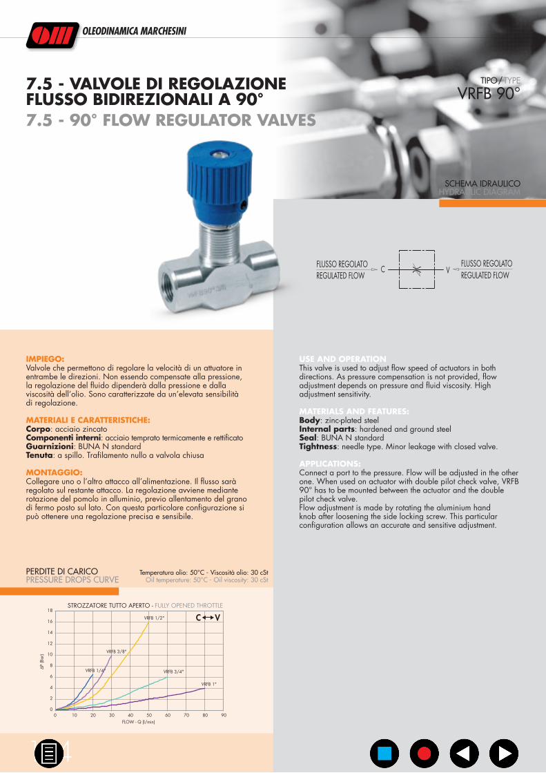
PERDITE DI CARICOPRESSURE DROPS CURVE
SCHEMA IDRAULICOHYDRAULIC DIAGRAM
7.5 - VALVOLE DI REGOLAZIONEFLUSSO BIDIREZIONALI A 90°7.5 - 90° FLOW REGULATOR VALVES
IMPIEGO:Valvole che permettono di regolare la velocità di un attuatore in entrambe le direzioni. Non essendo compensate alla pressione, la regolazione del fluido dipenderà dalla pressione e dalla viscosità dell’olio. Sono caratterizzate da un’elevata sensibilità di regolazione.
MATERIALI E CARATTERISTICHE:Corpo: acciaio zincatoComponenti interni: acciaio temprato termicamente e rettificatoGuarnizioni: BUNA N standardTenuta: a spillo. Trafilamento nullo a valvola chiusa
MONTAGGIO:Collegare uno o l’altro attacco all’alimentazione. Il flusso sarà regolato sul restante attacco. La regolazione avviene mediante rotazione del pomolo in alluminio, previo allentamento del grano di fermo posto sul lato. Con questa particolare configurazione si può ottenere una regolazione precisa e sensibile.
USE AND OPERATIONThis valve is used to adjust flow speed of actuators in both directions. As pressure compensation is not provided, flow adjustment depends on pressure and fluid viscosity. High adjustment sensitivity.
MATERIALS AND FEATURES:Body: zinc-plated steelInternal parts: hardened and ground steelSeal: BUNA N standardTightness: needle type. Minor leakage with closed valve.
APPLICATIONS:Connect a port to the pressure. Flow will be adjusted in the other one. When used on actuator with double pilot check valve, VRFB 90° has to be mounted between the actuator and the double pilot check valve.Flow adjustment is made by rotating the aluminium hand knob after loosening the side locking screw. This particular configuration allows an accurate and sensitive adjustment.
TIPO/TYPE
VRFB 90°
Temperatura olio: 50°C - Viscosità olio: 30 cStOil temperature: 50°C - Oil viscosity: 30 cSt

7
CODICECODE
SIGLATYPE
PORTATA MAXMAX FLOW
Lt./min
PRESSIONE MAXMAX PRESSURE
Bar
V0584 VRFB 90° ¼” 15 350
V0586 VRFB 90° ⅜” 30 350
V0587 VRFB 90° ½” 50 350
V0589 VRFB 90° ¾” 80 280
V0577 VRFB 90° 1” 80 250
CODICECODE
SIGLATYPE
V - C L D D1 H S PESOWEIGHT
GAS mm mm mm mm mm Kg
V0584 VRFB 90° ¼” G ¼” 60 M22x1,5 32 82 25 0,366
V0586 VRFB 90° ⅜” G ⅜” 61 M22x1,5 32 82 25 0,352
V0587 VRFB 90° ½” G ½” 70 M22x1,5 32 87 30 0,468
V0589 VRFB 90° ¾” G ¾” 89 M35x1,5 42 108,5 40 1,100
V0577 VRFB 90° 1” G 1” 90 M35x1,5 42 129 40 1,000
S
D1
D
L
H
C V
www.oleodinamicamarchesini.com
145

EP
B
CODICECODE
SIGLATYPE
PORTATA MAX ENTRANTEMAX INLET FLOW
Lt./min
PORTATA MAX REGOLATAMAX ADJUSTED FLOW
Lt./min
PRESSIONE MAXMAX PRESSURE
Bar
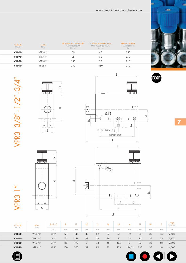
V1060 VPR3 ⅜” 50 40 250
V1070 VPR3 ½” 85 60 250
V1080 VPR3 ¾” 150 90 210
V1090 VPR3 1” 250 150 210
CODICECODE
SIGLATYPE
E – P – S L L1 L2 L3 L4 L5 L6 H H1 S PESOWEIGHT
GAS mm mm mm mm mm mm mm mm mm mm Kg
V1060 VPR3 ⅜” G ⅜” 121 147 40 32 36 55 12 80 35 35 2,530
V1070 VPR3 ½” G ½” 121 147 37 36 36 55 12 80 35 35 2,470
V1080 VPR3 ¾” G ¾” 155 190 67 44 45 135 8 90 35 50 2,400
V1090 VPR3 1” G 1” 150 205 39 80 70 133 114,5 135 35 60 4,000
0
5
10
15
20
25
30
35
0 20 40 60 80 100 120 140 160 180 200PRESSIONE RAMO B - B PORT PRESSURE (Bar)
FLU
SSO
REG
OLA
TORE
GU
LATE
D F
LOW
(l/m
in)
0 20 40 60 80 100 120 140 160 180 200PRESSIONE RAMO P - P PORT PRESSURE (Bar)
FLU
SSO
REG
OLA
TORE
GU
LATE
D F
LOW
(l/m
in)
PRESSIONE RAMO P - P PORT PRESSURE (Bar) PRESSIONE RAMO B - B PORT PRESSURE (Bar)
FLU
SSO
REG
OLA
TORE
GU
LATE
D F
LOW
(l/m
in)
FLU
SSO
REG
OLA
TORE
GU
LATE
D F
LOW
(l/m
in)
0 50 100 150 200 0 50 100 150 2000
10
20
30
40
50
60
60
60
60
PRESSIONE RAMO P - P PORT PRESSURE (Bar) PRESSIONE RAMO B - B PORT PRESSURE (Bar)
FLU
SSO
REG
OLA
TORE
GU
LATE
D F
LOW
(l/m
in)
FLU
SSO
REG
OLA
TORE
GU
LATE
D F
LOW
(l/m
in)
0
20
40
60
80
100
120
140
160
0 50 100 150 200 0 50 100 150 200
0
10
20
30
40
50
60
0 20 40 60 80 100 120 140 160 180 200PRESSIONE RAMO P - P PORT PRESSURE (Bar)
0 20 40 60 80 100 120 140 160 180 200PRESSIONE RAMO B - B PORT PRESSURE (Bar)
FLU
SSO
REG
OLA
TORE
GU
LATE
D F
LOW
(l/m
in)
FLU
SSO
REG
OLA
TORE
GU
LATE
D F
LOW
(l/m
in)
OLEODINAMICA MARCHESINI
146
SCHEMA IDRAULICOHYDRAULIC DIAGRAM
7.6 - VALVOLA PRIORITARIA A 3 VIE 7.6 - 3 PORT FLOW CONTROL VALVEONGOING PRESSURE LINE
IMPIEGO:Valvola che consente di mantenere costante la portata in “P” ad un valore stabilito, indipendentemente dalla pressione richiesta e dalla portata in entrata alla valvola. La portata in eccesso viene scaricata in “B” ed è disponibile per un secondo utilizzo. Anche la bocca “B” è insensibile alle variazioni di pressione ma non alle variazioni di portata.
MATERIALI E CARATTERISTICHE:Corpo: acciaio zincatoComponenti interni: acciaio temprato termicamente e rettificatoGuarnizioni: BUNA N standardTenuta: per accoppiamento. Trafilamento minimo (poche gocce al minuto)
MONTAGGIO:Collegare E all’alimentazione e P all’attuatore o alla linea di un impianto idraulico in cui si necessita la regolazione della portata. Collegare B al serbatoio o ad un secondo attuatore. Per regolare la portata in entrata al ramo P avvitare o svitare il volantino previo allentamento della ghiera di fermo.
USE AND OPERATIONThis valve enables to keep “P” flow constant to a certain setting, independently of the required pressure or the inlet flow of the valve. Exceeded flow is drained in “B” and it is available for a second use. Also port “B” is insensitive to pressure changes but not to flow changes.
MATERIALS AND FEATURES:Body: zinc-plated steelInternal parts: hardened and ground steelSeal: BUNA N standardTightness: by diameter combination. Minor leakage (few drops per minute)
APPLICATIONS:Connect E to the pressure flow and P to the actuator or to a line of an hydraulic circuit where flow adjustment is needed. Connect B to the tank or to a second actuator. To adjust inlet pressure in P screw in or off hand wheel after loosening the locknut.
TIPO/TYPE
VPR3
Temperatura olio: 50°C - Viscosità olio: 30 cStOil temperature: 50°C - Oil viscosity: 30 cSt
DIAGRAMMA COMPENSAZIONECOMPENSATION CURVE
VPR3 ⅜”
VPR3 ¾” VPR3 1”
VPR3 ½”
7
CODICECODE
SIGLATYPE
PORTATA MAX ENTRANTEMAX INLET FLOW
Lt./min
PORTATA MAX REGOLATAMAX ADJUSTED FLOW
Lt./min
PRESSIONE MAXMAX PRESSURE
Bar
V1060 VPR3 ⅜” 50 40 250
V1070 VPR3 ½” 85 60 250
V1080 VPR3 ¾” 150 90 210
V1090 VPR3 1” 250 150 210
CODICECODE
SIGLATYPE
E – P – S L L1 L2 L3 L4 L5 L6 H H1 S PESOWEIGHT
GAS mm mm mm mm mm mm mm mm mm mm Kg
V1060 VPR3 ⅜” G ⅜” 121 147 40 32 36 55 12 80 35 35 2,530
V1070 VPR3 ½” G ½” 121 147 37 36 36 55 12 80 35 35 2,470
V1080 VPR3 ¾” G ¾” 155 190 67 44 45 135 8 90 35 50 2,400
V1090 VPR3 1” G 1” 150 205 39 80 70 133 114,5 135 35 60 4,000
E
BP
L1
L4
= =
S
L3 L2
L5
Ø10,5
HH1
L
L6
E
BP
L
L1
L5 ( VPR3 3/8" e 1/2")
L4
= =S
L3 L2
HH1
L6
L5 ( VPR3 3/4")
Ø8,5
www.oleodinamicamarchesini.com
147
VPR3
3/8
” - 1
/2” -
3/4
”VP
R3 1
”

PE
T
CODICECODE
SIGLATYPE
PORTATA MAX ENTRANTEMAX INLET FLOW
Lt./min
PORTATA MAX REGOLATAMAX ADJUSTED FLOW
Lt./min
PRESSIONE MAXMAX PRESSURE
Bar
V1110 RFP3 ⅜” 50 30 250
V1120 RFP3 ½” 85 50 250
CODICECODE
SIGLATYPE
E – P – S L L1 L2 L3 L4 H H1 S PESOWEIGHT
GAS mm mm mm Mm mm mm mm mm Kg
V1110 RFP3 ⅜” G ⅜” 90 116 25 32 20 90 35 35 2,170
V1120 RFP3 ½” G ½” 90 116 25 32 20 90 35 35 2,096
0
5
10
15
20
25
30
35
0 20 40 60 80 100 120 140 160 180 200
PRESSIONE RAMO P - P PORT PRESSURE (Bar)
FLU
SSO
REG
OLA
TO -
REG
ULA
TED
FLO
W
(l/m
in)
0
10
20
30
40
50
60
0 20 40 60 80 100 120 140 160 180 200PRESSIONE RAMO P - P PORT PRESSURE (Bar)
FLU
SSO
REG
OLA
TO -
REG
ULA
TED
FLO
W
(l/m
in)
OLEODINAMICA MARCHESINI
148
SCHEMA IDRAULICOHYDRAULIC DIAGRAM
7.7 - REGOLATORE DI FLUSSO PRIORITARIO A 3 VIE7.7 - 3 PORT FLOW CONTROLVALVE EXCESS TO TANK
IMPIEGO:Valvola che consente di mantenere costante la portata in P ad un valore stabilito, indipendentemente dalla pressione richiesta e dalla portata in entrata alla valvola. La portata in eccesso viene mandata direttamente allo scarico T (serbatoio).
MATERIALI E CARATTERISTICHE:Corpo: acciaio zincatoComponenti interni: acciaio temprato termicamente e rettificatoGuarnizioni: BUNA N standardTenuta: per accoppiamento. Trafilamento minimo (poche gocce al minuto)
MONTAGGIO:Collegare E all’alimentazione e P alla rete in cui si necessita la regolazione della portata. Collegare T al serbatoio. Per regolare la portata in entrata avvitare o svitare il volantino previo allentamento della ghiera di fermo.
USE AND OPERATIONThis valve enables to keep “P” flow constant to a certain setting, independently of the required pressure or the inlet flow of the valve. Exceeded flow is drained directly in T (tank).
MATERIALS AND FEATURES:Body: zinc-plated steelInternal parts: hardened and ground steelSeal: BUNA N standardTightness: by diameter combination. Minor leakage (few drops per minute)
APPLICATIONS:Connect E to the pressure flow and P to the net where flow adjustment is needed. Connect T to the tank. To adjust inlet pressure in P screw in or off hand wheel after loosening the locknut.
TIPO/TYPE
RFP3
Temperatura olio: 50°C - Viscosità olio: 30 cStOil temperature: 50°C - Oil viscosity: 30 cSt
DIAGRAMMA COMPENSAZIONECOMPENSATION CURVE
RFP3 ⅜” RFP3 ½”

7
CODICECODE
SIGLATYPE
PORTATA MAX ENTRANTEMAX INLET FLOW
Lt./min
PORTATA MAX REGOLATAMAX ADJUSTED FLOW
Lt./min
PRESSIONE MAXMAX PRESSURE
Bar
V1110 RFP3 ⅜” 50 30 250
V1120 RFP3 ½” 85 50 250
CODICECODE
SIGLATYPE
E – P – S L L1 L2 L3 L4 H H1 S PESOWEIGHT
GAS mm mm mm Mm mm mm mm mm Kg
V1110 RFP3 ⅜” G ⅜” 90 116 25 32 20 90 35 35 2,170
V1120 RFP3 ½” G ½” 90 116 25 32 20 90 35 35 2,096
L
L1
L2
L3
L4
= =
S
HH1
P
T
E
P
855
52
Ø8,5
www.oleodinamicamarchesini.com
149
C V
CODICECODE
SIGLATYPE
G L L1 L2 H D E/ E/1 PESOWEIGHT
GAS mm mm mm mm mm mm mm Kg
R1351 VITE STROZZATRICE ¼” G ¼” 36 53 15 7 2,5 13 19 0,046
R1361 VITE STROZZATRICE ⅜” G ⅜” 39 58 15 8 3 13 22 0,074
OLEODINAMICA MARCHESINI
150
SCHEMA IDRAULICOHYDRAULIC DIAGRAM
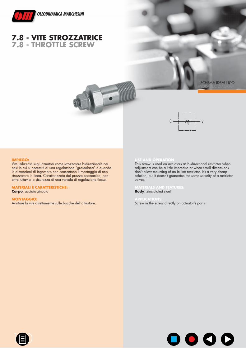
7.8 - VITE STROZZATRICE7.8 - THROTTLE SCREW
IMPIEGO:Vite utilizzata sugli attuatori come strozzatore bidirezionale nei casi in cui si necessiti di una regolazione “grossolana” o quando le dimensioni di ingombro non consentono il montaggio di uno strozzatore in linea. Caratterizzato dal prezzo economico, non offre tuttavia la sicurezza di una valvola di regolazione flusso.
MATERIALI E CARATTERISTICHE:Corpo: acciaio zincato
MONTAGGIO:Avvitare la vite direttamente sulle bocche dell’attuatore.
USE AND OPERATIONThis screw is used on actuators as bi-directional restrictor when adjustment can be a little imprecise or when small dimensions don’t allow mounting of an in-line restrictor. It’s a very cheap solution, but it doesn’t guarantee the same security of a restrictor valves.
MATERIALS AND FEATURES:Body: zinc-plated steel
APPLICATIONS:Screw in the screw directly on actuator’s ports

7
CODICECODE
SIGLATYPE
G L L1 L2 H D E/ E/1 PESOWEIGHT
GAS mm mm mm mm mm mm mm Kg
R1351 VITE STROZZATRICE ¼” G ¼” 36 53 15 7 2,5 13 19 0,046
R1361 VITE STROZZATRICE ⅜” G ⅜” 39 58 15 8 3 13 22 0,074
G
M8
L2L
H
L1
ØD
E/1
E/
www.oleodinamicamarchesini.com
151